US9209652B2 - Mobile device with scalable map interface for zone based energy management - Google Patents
Mobile device with scalable map interface for zone based energy managementDownload PDFInfo
- Publication number
- US9209652B2 US9209652B2US13/287,248US201113287248AUS9209652B2US 9209652 B2US9209652 B2US 9209652B2US 201113287248 AUS201113287248 AUS 201113287248AUS 9209652 B2US9209652 B2US 9209652B2
- Authority
- US
- United States
- Prior art keywords
- site
- network
- energy
- mobile device
- data
- Prior art date
- Legal status (The legal status is an assumption and is not a legal conclusion. Google has not performed a legal analysis and makes no representation as to the accuracy of the status listed.)
- Active
Links
Images


Classifications
- H02J13/001—
- F—MECHANICAL ENGINEERING; LIGHTING; HEATING; WEAPONS; BLASTING
- F24—HEATING; RANGES; VENTILATING
- F24F—AIR-CONDITIONING; AIR-HUMIDIFICATION; VENTILATION; USE OF AIR CURRENTS FOR SCREENING
- F24F11/00—Control or safety arrangements
- F24F11/30—Control or safety arrangements for purposes related to the operation of the system, e.g. for safety or monitoring
- F24F11/46—Improving electric energy efficiency or saving
- F24F11/47—Responding to energy costs
- F—MECHANICAL ENGINEERING; LIGHTING; HEATING; WEAPONS; BLASTING
- F24—HEATING; RANGES; VENTILATING
- F24F—AIR-CONDITIONING; AIR-HUMIDIFICATION; VENTILATION; USE OF AIR CURRENTS FOR SCREENING
- F24F11/00—Control or safety arrangements
- F24F11/50—Control or safety arrangements characterised by user interfaces or communication
- F24F11/52—Indication arrangements, e.g. displays
- F24F11/523—Indication arrangements, e.g. displays for displaying temperature data
- F—MECHANICAL ENGINEERING; LIGHTING; HEATING; WEAPONS; BLASTING
- F24—HEATING; RANGES; VENTILATING
- F24F—AIR-CONDITIONING; AIR-HUMIDIFICATION; VENTILATION; USE OF AIR CURRENTS FOR SCREENING
- F24F11/00—Control or safety arrangements
- F24F11/50—Control or safety arrangements characterised by user interfaces or communication
- F24F11/56—Remote control
- F24F11/58—Remote control using Internet communication
- F—MECHANICAL ENGINEERING; LIGHTING; HEATING; WEAPONS; BLASTING
- F24—HEATING; RANGES; VENTILATING
- F24F—AIR-CONDITIONING; AIR-HUMIDIFICATION; VENTILATION; USE OF AIR CURRENTS FOR SCREENING
- F24F11/00—Control or safety arrangements
- F24F11/62—Control or safety arrangements characterised by the type of control or by internal processing, e.g. using fuzzy logic, adaptive control or estimation of values
- F24F11/63—Electronic processing
- G—PHYSICS
- G05—CONTROLLING; REGULATING
- G05D—SYSTEMS FOR CONTROLLING OR REGULATING NON-ELECTRIC VARIABLES
- G05D23/00—Control of temperature
- G05D23/19—Control of temperature characterised by the use of electric means
- G05D23/1902—Control of temperature characterised by the use of electric means characterised by the use of a variable reference value
- G05D23/1905—Control of temperature characterised by the use of electric means characterised by the use of a variable reference value associated with tele control
- H—ELECTRICITY
- H02—GENERATION; CONVERSION OR DISTRIBUTION OF ELECTRIC POWER
- H02J—CIRCUIT ARRANGEMENTS OR SYSTEMS FOR SUPPLYING OR DISTRIBUTING ELECTRIC POWER; SYSTEMS FOR STORING ELECTRIC ENERGY
- H02J13/00—Circuit arrangements for providing remote indication of network conditions, e.g. an instantaneous record of the open or closed condition of each circuitbreaker in the network; Circuit arrangements for providing remote control of switching means in a power distribution network, e.g. switching in and out of current consumers by using a pulse code signal carried by the network
- H02J13/00001—Circuit arrangements for providing remote indication of network conditions, e.g. an instantaneous record of the open or closed condition of each circuitbreaker in the network; Circuit arrangements for providing remote control of switching means in a power distribution network, e.g. switching in and out of current consumers by using a pulse code signal carried by the network characterised by the display of information or by user interaction, e.g. supervisory control and data acquisition systems [SCADA] or graphical user interfaces [GUI]
- H—ELECTRICITY
- H02—GENERATION; CONVERSION OR DISTRIBUTION OF ELECTRIC POWER
- H02J—CIRCUIT ARRANGEMENTS OR SYSTEMS FOR SUPPLYING OR DISTRIBUTING ELECTRIC POWER; SYSTEMS FOR STORING ELECTRIC ENERGY
- H02J13/00—Circuit arrangements for providing remote indication of network conditions, e.g. an instantaneous record of the open or closed condition of each circuitbreaker in the network; Circuit arrangements for providing remote control of switching means in a power distribution network, e.g. switching in and out of current consumers by using a pulse code signal carried by the network
- H02J13/00004—Circuit arrangements for providing remote indication of network conditions, e.g. an instantaneous record of the open or closed condition of each circuitbreaker in the network; Circuit arrangements for providing remote control of switching means in a power distribution network, e.g. switching in and out of current consumers by using a pulse code signal carried by the network characterised by the power network being locally controlled
- H—ELECTRICITY
- H02—GENERATION; CONVERSION OR DISTRIBUTION OF ELECTRIC POWER
- H02J—CIRCUIT ARRANGEMENTS OR SYSTEMS FOR SUPPLYING OR DISTRIBUTING ELECTRIC POWER; SYSTEMS FOR STORING ELECTRIC ENERGY
- H02J13/00—Circuit arrangements for providing remote indication of network conditions, e.g. an instantaneous record of the open or closed condition of each circuitbreaker in the network; Circuit arrangements for providing remote control of switching means in a power distribution network, e.g. switching in and out of current consumers by using a pulse code signal carried by the network
- H02J13/00006—Circuit arrangements for providing remote indication of network conditions, e.g. an instantaneous record of the open or closed condition of each circuitbreaker in the network; Circuit arrangements for providing remote control of switching means in a power distribution network, e.g. switching in and out of current consumers by using a pulse code signal carried by the network characterised by information or instructions transport means between the monitoring, controlling or managing units and monitored, controlled or operated power network element or electrical equipment
- H02J13/00016—Circuit arrangements for providing remote indication of network conditions, e.g. an instantaneous record of the open or closed condition of each circuitbreaker in the network; Circuit arrangements for providing remote control of switching means in a power distribution network, e.g. switching in and out of current consumers by using a pulse code signal carried by the network characterised by information or instructions transport means between the monitoring, controlling or managing units and monitored, controlled or operated power network element or electrical equipment using a wired telecommunication network or a data transmission bus
- H02J13/00017—Circuit arrangements for providing remote indication of network conditions, e.g. an instantaneous record of the open or closed condition of each circuitbreaker in the network; Circuit arrangements for providing remote control of switching means in a power distribution network, e.g. switching in and out of current consumers by using a pulse code signal carried by the network characterised by information or instructions transport means between the monitoring, controlling or managing units and monitored, controlled or operated power network element or electrical equipment using a wired telecommunication network or a data transmission bus using optical fiber
- H—ELECTRICITY
- H02—GENERATION; CONVERSION OR DISTRIBUTION OF ELECTRIC POWER
- H02J—CIRCUIT ARRANGEMENTS OR SYSTEMS FOR SUPPLYING OR DISTRIBUTING ELECTRIC POWER; SYSTEMS FOR STORING ELECTRIC ENERGY
- H02J13/00—Circuit arrangements for providing remote indication of network conditions, e.g. an instantaneous record of the open or closed condition of each circuitbreaker in the network; Circuit arrangements for providing remote control of switching means in a power distribution network, e.g. switching in and out of current consumers by using a pulse code signal carried by the network
- H02J13/00032—Systems characterised by the controlled or operated power network elements or equipment, the power network elements or equipment not otherwise provided for
- H02J13/00034—Systems characterised by the controlled or operated power network elements or equipment, the power network elements or equipment not otherwise provided for the elements or equipment being or involving an electric power substation
- H—ELECTRICITY
- H02—GENERATION; CONVERSION OR DISTRIBUTION OF ELECTRIC POWER
- H02J—CIRCUIT ARRANGEMENTS OR SYSTEMS FOR SUPPLYING OR DISTRIBUTING ELECTRIC POWER; SYSTEMS FOR STORING ELECTRIC ENERGY
- H02J3/00—Circuit arrangements for AC mains or AC distribution networks
- H02J3/12—Circuit arrangements for AC mains or AC distribution networks for adjusting voltage in AC networks by changing a characteristic of the network load
- H02J3/14—Circuit arrangements for AC mains or AC distribution networks for adjusting voltage in AC networks by changing a characteristic of the network load by switching loads on to, or off from, network, e.g. progressively balanced loading
- F24F11/0012—
- F—MECHANICAL ENGINEERING; LIGHTING; HEATING; WEAPONS; BLASTING
- F24—HEATING; RANGES; VENTILATING
- F24F—AIR-CONDITIONING; AIR-HUMIDIFICATION; VENTILATION; USE OF AIR CURRENTS FOR SCREENING
- F24F11/00—Control or safety arrangements
- F24F11/30—Control or safety arrangements for purposes related to the operation of the system, e.g. for safety or monitoring
- F24F11/46—Improving electric energy efficiency or saving
- F—MECHANICAL ENGINEERING; LIGHTING; HEATING; WEAPONS; BLASTING
- F24—HEATING; RANGES; VENTILATING
- F24F—AIR-CONDITIONING; AIR-HUMIDIFICATION; VENTILATION; USE OF AIR CURRENTS FOR SCREENING
- F24F11/00—Control or safety arrangements
- F24F11/50—Control or safety arrangements characterised by user interfaces or communication
- F24F11/61—Control or safety arrangements characterised by user interfaces or communication using timers
- F24F2011/0047—
- F24F2011/0058—
- F24F2011/0071—
- F24F2011/0073—
- F24F2011/0075—
- F—MECHANICAL ENGINEERING; LIGHTING; HEATING; WEAPONS; BLASTING
- F24—HEATING; RANGES; VENTILATING
- F24F—AIR-CONDITIONING; AIR-HUMIDIFICATION; VENTILATION; USE OF AIR CURRENTS FOR SCREENING
- F24F2110/00—Control inputs relating to air properties
- F24F2110/10—Temperature
- F—MECHANICAL ENGINEERING; LIGHTING; HEATING; WEAPONS; BLASTING
- F24—HEATING; RANGES; VENTILATING
- F24F—AIR-CONDITIONING; AIR-HUMIDIFICATION; VENTILATION; USE OF AIR CURRENTS FOR SCREENING
- F24F2130/00—Control inputs relating to environmental factors not covered by group F24F2110/00
- F—MECHANICAL ENGINEERING; LIGHTING; HEATING; WEAPONS; BLASTING
- F24—HEATING; RANGES; VENTILATING
- F24F—AIR-CONDITIONING; AIR-HUMIDIFICATION; VENTILATION; USE OF AIR CURRENTS FOR SCREENING
- F24F2130/00—Control inputs relating to environmental factors not covered by group F24F2110/00
- F24F2130/10—Weather information or forecasts
- F—MECHANICAL ENGINEERING; LIGHTING; HEATING; WEAPONS; BLASTING
- F24—HEATING; RANGES; VENTILATING
- F24F—AIR-CONDITIONING; AIR-HUMIDIFICATION; VENTILATION; USE OF AIR CURRENTS FOR SCREENING
- F24F2140/00—Control inputs relating to system states
- F24F2140/60—Energy consumption
- G—PHYSICS
- G05—CONTROLLING; REGULATING
- G05B—CONTROL OR REGULATING SYSTEMS IN GENERAL; FUNCTIONAL ELEMENTS OF SUCH SYSTEMS; MONITORING OR TESTING ARRANGEMENTS FOR SUCH SYSTEMS OR ELEMENTS
- G05B2219/00—Program-control systems
- G05B2219/20—Pc systems
- G05B2219/26—Pc applications
- G05B2219/2642—Domotique, domestic, home control, automation, smart house
- H02J2003/143—
- H—ELECTRICITY
- H02—GENERATION; CONVERSION OR DISTRIBUTION OF ELECTRIC POWER
- H02J—CIRCUIT ARRANGEMENTS OR SYSTEMS FOR SUPPLYING OR DISTRIBUTING ELECTRIC POWER; SYSTEMS FOR STORING ELECTRIC ENERGY
- H02J2310/00—The network for supplying or distributing electric power characterised by its spatial reach or by the load
- H02J2310/10—The network having a local or delimited stationary reach
- H02J2310/12—The local stationary network supplying a household or a building
- H02J2310/14—The load or loads being home appliances
- Y—GENERAL TAGGING OF NEW TECHNOLOGICAL DEVELOPMENTS; GENERAL TAGGING OF CROSS-SECTIONAL TECHNOLOGIES SPANNING OVER SEVERAL SECTIONS OF THE IPC; TECHNICAL SUBJECTS COVERED BY FORMER USPC CROSS-REFERENCE ART COLLECTIONS [XRACs] AND DIGESTS
- Y02—TECHNOLOGIES OR APPLICATIONS FOR MITIGATION OR ADAPTATION AGAINST CLIMATE CHANGE
- Y02B—CLIMATE CHANGE MITIGATION TECHNOLOGIES RELATED TO BUILDINGS, e.g. HOUSING, HOUSE APPLIANCES OR RELATED END-USER APPLICATIONS
- Y02B70/00—Technologies for an efficient end-user side electric power management and consumption
- Y02B70/30—Systems integrating technologies related to power network operation and communication or information technologies for improving the carbon footprint of the management of residential or tertiary loads, i.e. smart grids as climate change mitigation technology in the buildings sector, including also the last stages of power distribution and the control, monitoring or operating management systems at local level
- Y02B70/3225—Demand response systems, e.g. load shedding, peak shaving
- Y02B70/3241—
- Y02B70/3275—
- Y—GENERAL TAGGING OF NEW TECHNOLOGICAL DEVELOPMENTS; GENERAL TAGGING OF CROSS-SECTIONAL TECHNOLOGIES SPANNING OVER SEVERAL SECTIONS OF THE IPC; TECHNICAL SUBJECTS COVERED BY FORMER USPC CROSS-REFERENCE ART COLLECTIONS [XRACs] AND DIGESTS
- Y02—TECHNOLOGIES OR APPLICATIONS FOR MITIGATION OR ADAPTATION AGAINST CLIMATE CHANGE
- Y02B—CLIMATE CHANGE MITIGATION TECHNOLOGIES RELATED TO BUILDINGS, e.g. HOUSING, HOUSE APPLIANCES OR RELATED END-USER APPLICATIONS
- Y02B90/00—Enabling technologies or technologies with a potential or indirect contribution to GHG emissions mitigation
- Y02B90/20—Smart grids as enabling technology in buildings sector
- Y—GENERAL TAGGING OF NEW TECHNOLOGICAL DEVELOPMENTS; GENERAL TAGGING OF CROSS-SECTIONAL TECHNOLOGIES SPANNING OVER SEVERAL SECTIONS OF THE IPC; TECHNICAL SUBJECTS COVERED BY FORMER USPC CROSS-REFERENCE ART COLLECTIONS [XRACs] AND DIGESTS
- Y04—INFORMATION OR COMMUNICATION TECHNOLOGIES HAVING AN IMPACT ON OTHER TECHNOLOGY AREAS
- Y04S—SYSTEMS INTEGRATING TECHNOLOGIES RELATED TO POWER NETWORK OPERATION, COMMUNICATION OR INFORMATION TECHNOLOGIES FOR IMPROVING THE ELECTRICAL POWER GENERATION, TRANSMISSION, DISTRIBUTION, MANAGEMENT OR USAGE, i.e. SMART GRIDS
- Y04S20/00—Management or operation of end-user stationary applications or the last stages of power distribution; Controlling, monitoring or operating thereof
- Y04S20/20—End-user application control systems
- Y04S20/222—Demand response systems, e.g. load shedding, peak shaving
- Y04S20/227—
- Y—GENERAL TAGGING OF NEW TECHNOLOGICAL DEVELOPMENTS; GENERAL TAGGING OF CROSS-SECTIONAL TECHNOLOGIES SPANNING OVER SEVERAL SECTIONS OF THE IPC; TECHNICAL SUBJECTS COVERED BY FORMER USPC CROSS-REFERENCE ART COLLECTIONS [XRACs] AND DIGESTS
- Y04—INFORMATION OR COMMUNICATION TECHNOLOGIES HAVING AN IMPACT ON OTHER TECHNOLOGY AREAS
- Y04S—SYSTEMS INTEGRATING TECHNOLOGIES RELATED TO POWER NETWORK OPERATION, COMMUNICATION OR INFORMATION TECHNOLOGIES FOR IMPROVING THE ELECTRICAL POWER GENERATION, TRANSMISSION, DISTRIBUTION, MANAGEMENT OR USAGE, i.e. SMART GRIDS
- Y04S20/00—Management or operation of end-user stationary applications or the last stages of power distribution; Controlling, monitoring or operating thereof
- Y04S20/20—End-user application control systems
- Y04S20/242—Home appliances
- Y04S20/244—Home appliances the home appliances being or involving heating ventilating and air conditioning [HVAC] units
- Y—GENERAL TAGGING OF NEW TECHNOLOGICAL DEVELOPMENTS; GENERAL TAGGING OF CROSS-SECTIONAL TECHNOLOGIES SPANNING OVER SEVERAL SECTIONS OF THE IPC; TECHNICAL SUBJECTS COVERED BY FORMER USPC CROSS-REFERENCE ART COLLECTIONS [XRACs] AND DIGESTS
- Y04—INFORMATION OR COMMUNICATION TECHNOLOGIES HAVING AN IMPACT ON OTHER TECHNOLOGY AREAS
- Y04S—SYSTEMS INTEGRATING TECHNOLOGIES RELATED TO POWER NETWORK OPERATION, COMMUNICATION OR INFORMATION TECHNOLOGIES FOR IMPROVING THE ELECTRICAL POWER GENERATION, TRANSMISSION, DISTRIBUTION, MANAGEMENT OR USAGE, i.e. SMART GRIDS
- Y04S40/00—Systems for electrical power generation, transmission, distribution or end-user application management characterised by the use of communication or information technologies, or communication or information technology specific aspects supporting them
- Y04S40/12—Systems for electrical power generation, transmission, distribution or end-user application management characterised by the use of communication or information technologies, or communication or information technology specific aspects supporting them characterised by data transport means between the monitoring, controlling or managing units and monitored, controlled or operated electrical equipment
- Y04S40/124—Systems for electrical power generation, transmission, distribution or end-user application management characterised by the use of communication or information technologies, or communication or information technology specific aspects supporting them characterised by data transport means between the monitoring, controlling or managing units and monitored, controlled or operated electrical equipment using wired telecommunication networks or data transmission busses
Definitions
- information infrastructureis lacking to enable utility companies and customers to access real-time energy consumption.
- some regionshave smart meters that are capable measuring and reporting consumption data.
- communication and analytical infrastructureto allow utility companies to analyze future demand and schedule energy production.
- some utilitiesare providing demand response systems that react to load levels, and force curtailment on residential, industrial, and commercial customers. Such programs have not been well received as they typically inconvenience the end user.
- FIG. 1illustrates a block diagram of an energy management system and energy transmission system according to an aspect of the disclosure
- FIG. 2illustrates a energy management system operable to manage energy at a site according to an aspect of the disclosure
- FIG. 3illustrates a flow diagram of a method of managing energy at a site according to an aspect of the disclosure
- FIG. 4illustrates a block diagram of a controller according to an aspect of the disclosure
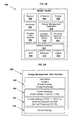
- FIG. 5Aillustrates a block diagram of a mobile device operable to be used with an energy management system according to another aspect of the disclosure
- FIG. 5Billustrates a block diagram of an energy management user interface according to another aspect of the disclosure
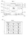
- FIG. 6Aillustrates a block diagram of an energy management system according to another aspect of the disclosure
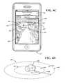
- FIG. 6Billustrates an energy management user interface according to an aspect of the disclosure
- FIG. 6Dillustrates a diagram of a plurality of zones defined by an energy management system according to another aspect of the disclosure
- FIG. 7illustrates an energy management user interface according to an aspect of the disclosure
- FIG. 8illustrates an energy management system interface operable to report energy usage and savings information according to a further aspect of the disclosure
- FIG. 9illustrates an energy management system interface operable to access and edit user and site information according to a further aspect of the disclosure
- FIG. 10illustrates an energy management scheduling user interface operable to schedule energy use at a residential site according to a further aspect of the disclosure
- FIG. 11illustrates an wireless thermostat user interface operable according to an aspect of the disclosure
- FIG. 13illustrates a block diagram of an energy network bridge according to a further aspect of the disclosure
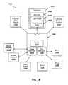
- FIG. 14illustrates a block diagram of a demand response system according to a further aspect of the disclosure.
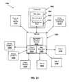
- FIG. 15illustrates a block diagram of a aggregate demand schedule system according to a further aspect of the disclosure.
- a communicative interactionmay be intending to send information, sending information, requesting information, receiving information, receiving a request for information, or any combination thereof.
- a communicative interactioncould be unidirectional, bidirectional, multi-directional, or any combination thereof.
- a communicative interactioncould be relatively complex and involve two or more network elements.
- a communicative interactionmay be “a conversation” or series of related communications between a client and a server—each network element sending and receiving information to and from the other.
- the communicative interaction between the network elementsis not necessarily limited to only one specific form.
- a network elementmay be a node, a piece of hardware, software, firmware, middleware, another component of a computing system, or any combination thereof.
- an energy management system, network device, or any combination thereofcan include any instrumentality or aggregate of instrumentalities operable to compute, classify, process, transmit, receive, retrieve, originate, switch, store, display, manifest, detect, record, reproduce, handle, or utilize any form of information, intelligence, or data for business, scientific, control, entertainment, or other purposes.
- an energy management systemcan include memory, one or more processing resources or controllers such as a central processing unit (CPU) or hardware or software control logic. Additional components of the energy management system can include one or more storage devices, one or more wireless, wired or any combination thereof of communications ports to communicate with external devices as well as various input and output (I/O) devices, such as a keyboard, a mouse, pointers, controllers, and display devices.
- the energy management systemcan also include one or more buses operable to transmit communications between the various hardware components, and can communicate using wireline communication data buses, wireless network communication, or any combination thereof.
- a flow charted technique, method, or algorithmmay be described in a series of sequential actions. Unless expressly stated to the contrary, the sequence of the actions and the party performing the actions may be freely changed without departing from the scope of the teachings. Actions may be added, deleted, or altered in several ways. Similarly, the actions may be re-ordered or looped. Further, although processes, methods, algorithms or the like may be described in a sequential order, such processes, methods, algorithms, or any combination thereof may be operable to be performed in alternative orders. Further, some actions within a process, method, or algorithm may be performed simultaneously during at least a point in time (e.g., actions performed in parallel), can also be performed in whole, in part, or any combination thereof.
- the terms “comprises,” “comprising,” “includes,” “including,” “has,” “having” or any other variation thereof,are intended to cover a non-exclusive inclusion.
- a process, method, article, system, or apparatus that comprises a list of featuresis not necessarily limited only to those features but may include other features not expressly listed or inherent to such process, method, article, system, or apparatus.
- “or”refers to an inclusive-or and not to an exclusive-or. For example, a condition A or B is satisfied by any one of the following: A is true (or present) and B is false (or not present), A is false (or not present) and B is true (or present), and both A and B are true (or present).
- FIG. 1illustrates a block diagram of an energy management system, illustrated generally at 100 , according to an aspect of the disclosure.
- Energy management system 100can include an energy source 102 configured to generate energy that can be coupled to an energy transmission system 104 to satisfy a load or demand at a first site 106 , second site 108 , third site 110 , or any combination thereof.
- Energy transmission system 104can be configured to be coupled to one or more of first site 106 , second site 108 , third site 110 , or any combination thereof.
- first site 106can include a distributed energy generation (DEG) asset 112 .
- DEG asset 112can include various types of energy producing assets such as a natural gas generator, fuel cell generator, solar array, solar concentrator, wind turbine generator, battery array, electric vehicle, hyrdo-power generator, any type of generator, or any combination thereof capable of outputting energy to energy transmission system 104 .
- second site 108can include a virtual capacity generation (VCG) asset 114 .
- VCG 114can include an energy consumption device configured to reduce energy consumption or load placed on energy transmission system 104 during various periods.
- VCG asset 108can include equipment located a commercial facility, industrial facility and the like.
- second site 102can include a retail center having energy consuming devices that can be managed to reduce energy consumption.
- second site 108can include a residential site having VCG assets that include energy consuming devices such as an HVAC system, heat pump, hot water heater, lighting systems, entertainments systems, refrigerators, or any type of electricity consuming device or system, or any combination thereof.
- third site 110can include a combination of a assets such as DEG asset 116 and a VCG asset 118 .
- first site 106can be coupled to server 120 using an Internet or broadband connection 122 .
- Second site 108can be coupled to server 120 using a second Internet or broadband connection 124 .
- Third site 110can be coupled to server 120 using a third Internet or broadband connection 126 .
- Various other types of connectionscan also be deployed by energy management system 100 as needed or desired.
- energy management system 100can utilize energy management information (EMI) to manage energy production, consumption, curtailment, load shedding, purchase decisions, demand response decisions, or any combination thereof.
- EMIcan include any combination of data sources such as real-time congestion data, energy transmission line operating conditions, syncrophasor data, firm owned alternative energy generator operating status, non-firm owned alternative energy generator operating status, locational marginal pricing data, congestion revenue rights data, energy storage capacity, stored energy output capacity, real time energy pricing data, historical energy pricing data, real time nodal demand data, historical nodal demand data, real time zonal demand data, historical zonal demand data, external market demand data, historical external market demand data, nodal price data, real time energy price data, real time energy demand data, historical energy demand data, historical energy price data, firm owned alternative energy generator data, non-firm owned alternative energy generator data, est.
- firm owned alternative energy generator output scheduleestimated non-firm owned alternative energy generator output schedule, macro environmental data, micro environmental data, real-time grid congestion data, historical grid congestion data, renewable energy credit information, carbon credit cap and trade pricing information, fixed and variable costs for operating alternative energy generators, production tax credit (PTC) pricing information, investment tax credit (ITC) information, federal grant information, credit-to-grant comparison analysis data, PTC to ITC analysis data, interest/finance data for alternative energy generators, asset depreciation schedules, available solar and wind output capacity, distributed energy production scheduling data, feed-in tariff data, baseline energy generator data, load utilization data, transmission efficiency data, congestion right revenue data, priority dispatch data, federal renewable portfolio standard (RPS) data, state renewable portfolio standard (RPS) data, net-metering data, current or forecasted % coal production data, current or forecasted % natural gas production data, current or forecasted % green house gas production data, current or future coal pricing data, current or future natural gas pricing data, current or future oil pricing data, current or future energy transmission pricing
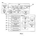
- FIG. 2illustrates an energy management system, illustrated generally at 200 and configured to be used at a site 202 according to an aspect of the disclosure.
- Site 202can include a residential site, and industrial site, a manufacturing site, a commercial site, or any combination thereof.
- energy management system 200can include a server 204 located at a remote location that can be communicatively coupled to a network 206 .
- site 202can include a controller 216 capable of connecting to a wireless thermostat (TSTAT) 208 , an associated mobile device 210 , one or more smart appliances 212 , a distributed energy generating asset 214 , or any combination thereof.
- TTATwireless thermostat
- controller 216can establish a wireless energy network 242 using a wireless communication described herein.
- Various combinations of networks and variants thereofcan also be deployed by controller 216 to establish wireless energy network 242 .
- mobile device 210can communicate with controller 216 using a WIFI or 802.11 based communication, Bluetooth communication, Zigbee communication, or various other wireless communication, or any combination thereof.
- mobile device 210an communicate with an information network 240 using a subscriber based wireless data communication network such as a 3G network, 4G network, EDGE network, a cellular network, WiMAX, other wireless data communication, or any combination thereof.
- site 202can include a gateway 218 configured as a broadband gateway such as a DSL gateway, cable system gateway, fiber optic gateway, or any combination thereof.
- energy management system 200can include an advanced metering infrastructure (AMI) gateway 242 configured to communicate with a smart metering device 250 .
- AMIadvanced metering infrastructure
- Smart metering device 250can include a utility or power company owned metering device and can be configured to communicate using a wireless network such as a cellular network, a mesh network, WiMAX network, or any combination thereof.
- controller 216can communicate with AMI gateway 242 using an AMI network 248 communicated by AMI gateway 242 .
- energy management system 200can include server 204 configurable to include various energy management logic, modules, interfaces, database sources, or various combinations thereof to manage energy use at site 200 .
- Server 204can also include a processor 222 that can be configured as multiple processors having one or more processing cores as needed or desired, one or more databases 224 that can be internal or external to server 204 , and memory 226 configurable to store data.
- server 204can be located in a single location however multiple locations, and server configurations including cloud computing, distributed computing, dedicated computing, or any combination thereof can be deployed.
- controller 216can include portions or all of server 204 and can deploy some or all of the capabilities of server 204 .
- server 204can include a site interface 220 operable to be coupled to network 206 and gateway 218 to communicate data between site 202 and server 204 .
- Server 204can also include a mobile client interface 226 that can be coupled to a wireless telecommunications communication gateway such as a WAP gateway and the like.
- mobile client interface 226can communicate with one or more mobile devices 210 , using information network 240 or another data network provided by a wireless telecommunications provider.
- Mobile client interface 226 , mobile device 210 , an information network 240 , or various combinations thereofcan include secure connection capabilities such as SSL connections or other carrier supported secure connection capabilities.
- Server 204can also include an energy price monitor 228 , a demand response module 230 , an efficiency rating module 232 , a proximity detection module 234 , a scheduling module 236 , an energy savings module 238 , a messaging module 240 , or any combination thereof.
- energy price monitor 228can be deployed by processor 222 and can access EMI stored within database 224 or a remote data source to monitor energy pricing of site 202 .
- demand response module 230can be deployed by processor 222 and can access EMI stored within database 224 or a remote data source to manage demand response preferences and capabilities of site 202 .
- efficiency rating module 232can be deployed by processor 222 and can access EMI stored within database 224 or a remote data source to determine an efficiency rating, thermal response, virtual capacity capabilities, performance data, or various other of site 202 .
- proximity detection module 234can be deployed by processor 222 and can access EMI stored within database 224 or a remote data source to detect a location of mobile device 210 relative to site 202 , and modify operating conditions of site 202 based on a proximity of mobile device 210 to site 202 .
- scheduling module 236can be deployed by processor 222 and can access EMI stored within database 224 or a remote data source to schedule energy use or operations of one or more energy consuming devices at site 202 .
- energy savings module 238can be deployed by processor 222 and can access EMI stored within database 224 or a remote data source to determine a past or forecasted energy savings of site 202 .
- server 204can include user account login information at a utility company or energy provider that can enable a user to gain access to meter data.
- energy savings module 238can pull EMI data stored at a third party website, and output past or forecasted energy savings of site 202 .
- messaging module 240can be deployed by processor 222 and can access EMI stored within database 224 or a remote data source to communicate messages.
- messaging module 240can use an email address, mobile device identifier, SMS gateway data, network device identifier data, IP address of controller 216 , IP address of gateway 218 , IP address of AMI gateway 242 , or any combination thereof to communicate messages or other energy management information.
- controller 216can access consumption data at site 202 using AMI gateway 242 .
- controller 216can include a wireless communication module (not expressly illustrated in FIG. 2 ) such as a Zigbee communication module (e.g. 802.15.4), WIFI module, Bluetooth module or various other wireless modules, or any combination thereof.
- Controller 216can include one or more profiles stored within a memory device (not expressly illustrated in FIG. 2 ) configured to include data that will enable controller 216 to join AMI gateway 242 .
- a profilecan include various attributes to initiate or establish communication using one or more security levels as needed or desired.
- energy management system 200can be used with an energy management application accessible or deployed by mobile device 210 or other computing device.
- the energy management applicationcan be used to control TSTAT 208 , one or more smart appliances 212 or various other devices at site 202 .
- a usercan access the energy management application using mobile device 210 or other computing device and read the current settings, operating conditions, or various other types of energy management information associated with site 202 .
- a usercan view if TSTAT 208 and an associated HVAC system (not expressly illustrated in FIG. 2 ) is on or off, a mode such as heat, A/C, or fan, or any combination thereof.
- the usercan use the energy management application to access multiple thermostats or zones at site 202 .
- the energy management applicationmay access multiple thermostats of different manufacturers. Although the energy management application has been described in the context of accessing TSTAT 208 , it should be understood that other network devices, smart appliances, lighting systems, or any other energy consuming or network accessible device or any combination thereof can be accessed using the energy management application.
- mobile device 210can include a mobile device application that can upload location data to server 204 , controller 216 , TSTAT 210 , smart appliances 212 , various other devices capable of receiving location data, or any combination thereof.
- mobile device 210can report a current location using a location application program interface (API) of mobile device 210 , and can upload location data to server 204 using mobile client interface 226 .
- APIlocation application program interface
- Server 204can then deploy proximity detection module 234 to determine whether one or more operating conditions should be altered at site 202 .
- proximity detection module 234can include rules based logic to determine if an operating condition of a resource at site 202 should be altered.
- server 204can generate a control action report to be communicated to site 202 .
- a control action reportcan include adjusting TSTAT 208 up a specific number of degrees relative based on the distance and direction a user may be from site 202 .
- a usermay have previously established an upper setting limit a user would like an internal temperature to reach at site 202 without having an associated HVAC unit turning on.
- the upper setting limitcan be sent to TSTAT 208 based on how far a user may be from site 202 .
- a lower limitcan be established for a heating unit as well. These limits can be entered using mobile device 210 , a web-based user interface, or any combination thereof.
- server 204can characterize site 202 to determine operating characteristics and performance data of site 202 and associated energy consuming devices at site 202 .
- server 204can use efficiency rating module 232 to monitor performance data at site 202 .
- Performance datacan include measured performance data detected by controller 216 , performance specifications of an energy consuming device that can be based on a model number or other identification data of the device, the size or square footage of site 202 , efficiency improvements or specifications of site 202 , various other EMI data, or any combination thereof.
- an energy alertcan be sent using messaging module 240 .
- an energy alertcan be sent to a third party to initiate a service call at site 202 .
- Server 204can include a lead generation module (not expressly illustrated in FIG. 2 ) that can be communicated using messaging module 240 to a subscriber such as a service company, appliance provider, and the like.
- performance datacan be used to determine when to adjust an operating condition of an energy consuming device based on a schedule, proximal location of the user and mobile device, in response to a demand response event, in response to a consumer setting of a desired operating condition based on an energy savings mode (e.g. low, med, high), or any combination thereof.
- an energy savings modee.g. low, med, high
- controller 216can be configured as a plug-device that can be plugged directly to a wall socket or other power receptacle and can include various components (not expressly shown in FIG. 2 ). Controller 216 can also include a network interface or Ethernet port, one or more USB interfaces or mini-USB interfaces, an SDIO slot, additional data or plug interfaces, or any combination thereof. Controller 216 can include an internal or external AC, DC, AC to DC converter power module, or any combination thereof to power controller 216 . According to an aspect, controller 216 can be provided as a small form factor unit to allow for easy installation, use, and discretionary placement.
- controller 216can include a plug computer based on Marvell Corporation's Kirkwood® microprocessor, Part Number 6281 and associated components.
- controller 216can include a plug computer including specifications described in “Sheeva Plug Development Kit Reference Design”, version 1.1, and previous versions which are herein incorporated by reference. Other processors having various other speeds and supporting components can also be used.
- controller 216can include various buses that can be used to install one or more wireless modules.
- controller 216can include a UART bus interface that can be used to interface a Zigbee module, WIFI module, Bluetooth Module, various other modules or combinations thereof.
- Controller 216can include buses that can be located internal or external to a housing of controller 216 .
- energy management system 200can include one or more network devices, such as TSTAT 208 , smart appliances 212 , or various other network devices installed at a residential site such as a home or residence.
- Controller 216can establish a wireless energy network 242 capable of communicating with a network device at site 202 .
- Energy management system 200can also include server 204 disposed remotely from site 202 and capable of generating a control action report to control the network device.
- Controller 216can also be located at site 202 including a residential site.
- Controller 202can be in communication with server 204 .
- controller 202can establish initiate a plurality of operating status requests of the network device, and receive device data in response to at least one of the operating status requests.
- Controller 202can further generate a site report including the device data, and initiate a communication of the site report to server 204 .
- controller 202can detect an availability of a control action report at server 202 in conjunction with the communication of the site report. As such, a secure connection can be initiated from site 202 to communicate site reports and receive control action reports without having to have server 204 initiate a communication with site 202 .
- server 202can generate control action report prior to a site report upload, in association with a site report upload, or any combinations thereof.
- one or more control action reportscan be generated and queued in advance of a site report upload.
- a control action reportcan be generated during a site report upload.
- a control action reportcan be generated in response to information uploaded within the site report.
- various combinations of control action report generation techniquescan be deployed as needed or desired.
- energy management system 200can be used to generate a control action report in response to a distance mobile client 210 may be from site 202 .
- site 202can include a network device, such as TSTAT 208 , joined to wireless energy network 242 .
- controller 216can be configured to establish wireless energy network 242 using a wireless mesh network and initiate a plurality of operating status requests.
- controller 216can access TSTAT 208 using wireless energy network 242 at a first operating status request interval.
- Controller 216can be used to generate a site report that can include device data of TSTAT 208 at a site report interval.
- a site report intervalcan be the same interval as the first operating status request interval. In other forms, each interval can be different.
- the first operating status report request intervalcan be set to thirty seconds and the site report interval can be set to sixty seconds. As such, two cycles of data can be acquired.
- Various combinations of intervalscan be used as desired.
- controller 216can initiate a communication of site report to a remote server such as server 204 using gateway 218 .
- gateway 218can include a residential broadband connection 206 capable of establishing a secure gateway connection between site 202 and server 204 using a public communication network.
- residential broadband connection 206does not include a cellular communications based network.
- control datacan be provided in response to a detection of a travel direction and a distance between mobile device 210 having location reporting device, and site 202 .
- server 204can detect a direction and distance mobile device 210 may be from residential site 202 .
- Server 204can then determine if a control action should be generated.
- TSTAT 208 settingcan be adjusted up during a warm or summer season (or down during a cold or winter season) to reduce energy consumption.
- Other network devicescan also be adjusted as needed or desired.
- energy management system 200can use energy pricing monitor 228 to generate a control action report.
- energy pricing monitor 228can be configured to detect energy pricing within an energy market, and initiate curtailing use of a network device, such as TSTAT 208 , smart appliance 212 , other network devices at site 202 , or any combination thereof.
- energy pricing monitor 228can output a control action report in response to an unfavorable pricing condition, and further upon the detection of a travel direction and a distance between mobile device 210 and site 202 .
- energy pricing monitor 228can also initiate use of one or more network devices at site 202 in response to a favorable pricing condition, and a detection of a travel direction and a distance between mobile device 210 and residential site 202 . In this manner, a user's travel direction, distance, and current energy pricing within a market can be used to determine how energy consumption can occur at site 202 .
- energy management system 200can also use demand response module 230 to detect a demand response condition and respond accordingly.
- demand response module 230can be used to detect a grid condition favorable to a demand response event and detect a profile preference setting of an user or site manager of site 202 .
- a user or site managercan set a profile to always participate, not participate, or have a request sent to collaborate on whether to participate.
- Other profile settingscan also be used such as determining an economic or monetary value to a user or site manager if participating in a demand response event.
- a favorable grid conditioncan include an increase in the price of energy due to an undersupply of energy within an energy transmission system or market (not expressly illustrated in FIG. 2 ).
- a favorable conditioncan include an oversupply of energy purchased by an energy provider of site 202 . Additionally, a high demand period can be detected and the oversupply of energy can be increased using a demand response event.
- a favorable grid conditioncan include a time interval when transmission pricing to use an energy transmission system may be determined. As such, an energy provider would receive an economic benefit from reducing load when the transmission rate or rate for using transmission lines would be determined.
- Various combinations of favorable grid conditionscan be detected as needed or desired in association with determining a demand response event to curtail energy use at site 202 .
- energy management system 200can use demand response module 230 configured to detect an energy capacity of site 202 having a residence.
- demand response module 230can detect a grid condition favorable to a demand response event, and can also detect a preference of an resident or owner of the residence to participate in demand response events.
- Demand response module 230can also determine an energy capacity of site 202 using historical device consumption data received in a site report, and forecasted device consumption data. Control data can then be generated to alter an operating condition of the network device in response to the grid condition and the preference of the owner and the energy capacity of site 202 .
- server 204can determine an energy capacity of site 202 using device data received in association with site reports received from site 202 .
- site report datacan be used with efficiency rating module 232 to determine a virtual generation capacity or energy reduction capacity of site 202 .
- demand response module 230can output a curtailment action to be used within a control action report to be communicated to site 202 .
- a curtailment actioncan include an updated control data to alter a current operating condition of one or more network devices connected to wireless energy network 242 at site 202 .
- controller 216can be configured to detect a new set-point value within a control action report, and identify TSTAT 208 to be adjusted to the new set-point value.
- multiple wireless thermostatscan be accessed via wireless energy network 242 and adjusted as desired.
- Controller 216can communicate a different set-point values to each of the wireless thermostats.
- Controller 216can initiate an outputting of new set-point values to TSTAT 208 and others using wireless energy network 242 .
- energy management system 200can use proximity detection module 234 to detect a distance mobile device 210 may be from site 202 including a residential site.
- proximity detection module 234can access location data stored within database 224 and provided by mobile device 210 using mobile client interface 226 .
- Proximity detection module 234can further detect mobile device 210 within a first zone (e.g. less than one (1) mile from the site, less than three (3) miles from site, greater than five (5) miles from site, etc.).
- Proximity detection modulecan further detect a current thermostat setting of TSTAT 208 , and an indoor temperature detected at site 202 and communicated within a site data report communicated from site 202 .
- Proximity detection module 234can then determine a percentage adjustment to adjust a current setting of TSTAT 208 , and output the percentage adjustment as a new set-point value to be used within a control action report. For example, if mobile device 210 can be detect as being greater than three (3) miles from site 202 , TSTAT 208 can be adjusted to within 75% of the maximum setting in a summer season, or minimum setting in a winter season. As such, a site 202 can be managed based on a user's proximity to a site, which zone a user may be located in, and current seasonal schedule or setting being used at a site 202 .
- energy management system 200can include TSTAT 208 configured as a wireless thermostat capable of joining wireless energy network 242 operable as a wireless home energy network.
- TSTAT 208can be configured to not include an enabled local programming schedule configured to control an HVAC system of site 202 .
- TSTAT 208can include sufficient memory to store a set-point value, but may be not include scheduling capabilities at TSTAT 208 .
- a simplified user interface of TSTAT 208can be deployed. For example, if TSTAT 208 includes a scheduling feature, energy management system 200 can be used to disable the scheduling feature located at TSTAT 208 .
- TSTAT 208can be considered a non-programmable thermostat capable of connecting to wireless energy network 242 , and set-point values or other control actions can be received using wireless energy network 242 . In this manner, scheduling use of TSTAT 208 can be provided using on-line or web application based scheduling tool.
- controller 216can be further configured to initiate joining TSTAT 208 to wireless energy network 242 using a unique identifier of TSTAT 208 .
- a unique identifier of TSTAT 208can be received from server 204 and a local schedule and or scheduling capabilities of TSTAT 208 can be disabled. In this manner, an overall design complexity of a thermostat can be reduced and scheduling capabilities can be provided using a schedule created within a network environment and output by controller 216 , server 204 , mobile device 210 , or any combination of sources capable of providing schedule information or control action data to TSTAT 208 .
- energy management system 200can also use scheduling module 236 to schedule use of a network device located at site 202 and capable of connecting to wireless energy network 242 .
- multiple user schedulescan be stored within database 224 and used by site 202 .
- scheduling module 236can be used to detect a first user schedule accessible to controller 216 .
- the first user schedulecan include a first schedule event configured to alter an operating condition of a network device such as TSTAT 208 , smart appliance 212 , or other energy consuming network devices.
- the first user schedulecan be operably linked to mobile device 210 having a location detection device.
- the first user schedulecan be used or not used based on a distance mobile device 210 may be from residence 202 . In this manner, as user returns to residential site 202 , a user schedule can be activated and used.
- energy management system 200can include a second user schedule accessible to controller 216 .
- a second user schedulecan include scheduling data to schedule a second schedule event configured to alter an operating condition of a network device at site 202 .
- the second user schedulecan be operably linked to a second mobile device having a location reporting device (not expressly illustrated in FIG. 2 ).
- the second user schedulecan be used or not used based on a distance a second mobile device may be from site 202 .
- mobile device 210may not be located at site 202 , but a second mobile device may located be at site 202 .
- a second user schedulemay be based on detecting the second mobile device located at site 202 .
- the second user schedulecan be disabled when the second user leaves the site 202 and a proximity mode can be enabled.
- a second user schedulemay not be operably linked to any mobile device.
- controller 216can use a second user's schedule to schedule events in response to a detection of mobile device 210 being a distance away from residential site 202 . In this manner, multiple user schedules and proximity control of energy use can be deployed at a common site.
- energy management system 200can also include controller 242 capable of detecting advanced metering infrastructure (AMI) wireless network 248 output by smart metering device 250 .
- AMIadvanced metering infrastructure
- smart metering device 250can include, or can be coupled to, AMI/Gateway 242 capable of outputting AMI wireless network 248 .
- smart metering device 250can be configured to output AMI wireless network 248 directly.
- controller 216can be configured with a communication interface (not expressly illustrated in FIG. 2 ) to enable joining AMI wireless network 248 . In this manner, controller 216 can gain access to AMI wireless network 248 to receive AMI data. In a further aspect, controller 216 can use the AMI data to alter an operating condition of a network device at site 202 , output AMI data using a display of a network device, communicate AMI data to server 204 , or any combination thereof. According to a further aspect, controller 216 can communicate the AMI data with site report data as a site report to server 204 . As such, AMI data and site report data can be used at server 204 .
- controller 216can connect to AMI wireless network 248 at a first security level, and alter an operating condition of a network device connected to wireless energy network 242 at a second security level.
- wireless energy network 242can be deployed at the same security level as AMI wireless network 248 , can be deployed at a different security level than AMI wireless network 248 , or any combination thereof.
- a user or site profilecan be used to enable use of control actions initiated or received by AMI wireless network 248 .
- a site manager or usercan establish a profile setting to enable or disable a utility company to alter an operating condition of a network device at a residence.
- controller 216can access a profile setting prior to connecting to AMI wireless network 248 , enabling use of a control action received using the AMI wireless network 248 , or any combination thereof.
- controller 216can access server 204 to detect profile settings.
- mobile device 210can communicate with controller 216 to access site data, site reports, control action data, AMI data, or various other types of EMI data available using WIFI network 244 .
- mobile device 210can initiate control actions, control action reports, or combinations thereof that can alter an operating condition of a network device coupled to wireless energy network 242 .
- control action reportsor combinations thereof that can alter an operating condition of a network device coupled to wireless energy network 242 .
- controller 216configured with a WIFI communication device can enable a connection to a home computer system, laptop computer, Netbook, home server, IPAD®, home automation system, router, or other WIFI enabled system or devices (not expressly illustrated in FIG. 2 ), or any combination thereof.
- a usercan use an IPAD to access controller 216 .
- WIFI network 244 and wireless energy network 242a user can receive operating status information, initiate control actions of network devices, schedule energy use, or various other energy management activities.
- controller 216may not have access to network 206 .
- Controller 216can include portions or all of the capabilities of server 204 to schedule energy use, generate scheduling data, access site data, generate control action data, or any combination thereof.
- network 206may not be established (e.g. in a new construction site, etc.), or if a network failure or an absence of network availability occurs, a user can access network devices at site 202 and manage energy use.
- controller 216can detect when mobile device 210 connects to WIFI network 244 and alter an operating condition of a network device coupled to wireless energy network 242 . For example, as mobile device 210 moves or transitions away from site 202 , controller 216 can detect a signal loss and alter an operating condition at site 202 . According to an aspect, controller 216 can include control action data to be used upon detecting a signal loss. In other forms, controller 216 can report the signal loss to server 204 within, or external to a site report. Server 204 can then determine a control action (if any) in response to a reporting of the WIFI signal being lost.
- server 204can initiate a text message using messaging module 240 to be sent to mobile device 210 .
- User of mobile device 210can then view the text message and respond to alter an operating condition at site 202 .
- a usercan place site 202 in proximity mode which will enable an energy efficiency schedule associated with the user.
- a usercan access an energy management application accessible to mobile device 210 and alter an operating condition at site 202 .
- Various combinations of messaging communicationse.g.
- SMS text, email, social network messaging, social network postings, etc.), message content, and various combinations thereofcan be used to inform a user of mobile device 210 that an operating condition can be altered in response to mobile device 210 not being connected to a WIFI signal at site 202 , a detection of mobile device 210 being a distance from site 202 using location detection, or any combination thereof.
- controller 216can also connect to mobile device 210 using WIFI network 244 and communicate information using mobile device 210 and information network 240 .
- mobile device 210can connect to information network 240 which can be a wireless subscriber based information network.
- Mobile device 210can receive energy management information from an information source accessible to information network 240 .
- mobile device 210can include a mobile energy management application that can be used to access server 204 or other information source(s).
- Mobile device 210can be used to upload information such as a site report, network device data, operating statuses, or various other types of information that can be obtained at site 202 using wireless energy network 242 .
- mobile device 210can receive information such as control action reports, control data, environmental data, scheduling data, user profile data, network device profile data, Zigbee based profile data, WIFI data, configuration data, network device data updates or firmware updates, controller data updates or firmware updates, or various other types of EMI data or any combination thereof that can be communicated to mobile device 210 using information network 240 .
- Mobile device 210can then communicate received information to controller 216 using WIFI network 244 .
- Controller 216can use the received information to manage energy use at site 202 .
- controller 216can access wireless AMI network 248 to request a Zigbee profile.
- controller 216can be configured to request profile data, profile updates, network device updates, various other types of information to manage network device, or any combination thereof of a network device using one or more networks accessible to controller 216 .
- controller 216can be incorporated into a network device.
- controller 216 and TSTAT 208can be combined into the same unit.
- Controller 216can also include an 802.15.4 based wireless communication device (not expressly shown in FIG. 2 ) operable to establish wireless energy network 242 .
- Controller 216can also include an 802.11 based wireless communication device (not expressly shown in FIG. 2 ) operable to communicate with mobile device 210 .
- controller 216can communicate with gateway 218 having a residential broadband wireless router capable of establishing an 802.11 based wireless communication network at site 202 . In this manner, combining controller 216 and TSTAT 208 can lead to a reduction in the number of separate devices deployed at site 202 .
- controller 216can include a processor (not expressly illustrated in FIG. 2 ) configured to deploy a web server capable of enabling web services.
- controller 216can connect to WIFI network 244 and a computer system at site 202 .
- the computer systemcan include a browser configured to access an IP address of the web server of controller 216 to manage one or more network devices coupled to wireless energy network 242 .
- controller 216can include a scheduling tool configured to be output by the web server and accessible using WIFI network 244 .
- controller 216can be coupled to mobile device 210 and controller 216 can be configured to enable access to a subscriber based wireless information network 240 using a connection to the 802.11 based wireless communication device of controller 216 .
- FIG. 3illustrates a method of managing energy at a site according to an aspect of the disclosure. Portions or all of the method of FIG. 3 can be used with portions or all of the energy management systems, devices, or apparatuses disclosed herein, or any other type of system, controller, device, module, processor, or any combination thereof, operable to employ all, or portions of, the method of FIG. 3 . Additionally, the method can be embodied in various types of encoded logic including software, firmware, hardware, or other forms of digital storage mediums, computer readable mediums, or logic, or any combination thereof, operable to provide all, or portions, of the method of FIG. 3 .
- the methodbegins generally at block 300 .
- the methoddetects whether an energy network has been established.
- a wireless energy networkcan be established and can include one or more networks that can be used to manage energy use at a site.
- a wireless energy networkcan be established using a wireless enabled controller located at a residence.
- a detection of an energy network, AMI enabled network, WIFI enabled network, Zigbee enabled network, WiMAX network, or any other type of energy network, or any combination thereofcan be detected. If at decision block 302 , one or more networks may not be detected, the method can proceed to decision block 304 .
- the methodcan detect if there is an AMI network available.
- the networkcan proceed to block 306 and the AMI network can be joined.
- the AMI networkcan include a specific protocol and security level to establish communication or allow a joining of the network.
- the AMI networkmay require an encryption key-based security that can require specific keys, certificates, etc. to enable access.
- the AMI networkmay include a smart grid based security described in Smart Grid standards. As such, various combinations of joining the AMI network can be deployed.
- the methodcan proceed to decision block 308 .
- an AMI networkmay be available and the method can be modified to determine whether to join the AMI network. If at decision block 304 , an AMI network may not be detected (or may not be joined), the method can proceed to decision block 308 . At decision block 308 , the method can detect if a WIFI network (e.g. 802.11 based network) may be available. If a WIFI network is not detected or is not available, the method can proceed to block 310 and a WIFI network can be established.
- a controller, network device, smart appliance, or various other types of energy consuming devicescan include a WIFI communication device capable of initiating a WIFI network.
- a WIFI networkcan be established and the method can proceed to block 312 . If at decision block 308 a WIFI network exists, or if a WIFI network should not be established, the method can proceed to block 312 . In some forms, an additional WIFI network can be established at block 310 and the method can be modified to allow a bridging between the two WIFI networks.
- an energy networkcan be established to manage one or more network devices.
- an energy networkcan include a wireless energy network that is based on a Smart Grid standards and protocols such as a Zigbee based protocol.
- Various other types of communicationcan also be used to establish an energy network.
- An energy networkcan be established by outputting a wireless network at a site to enable a network device to join the energy network.
- an external information sourcecan be capable of providing a unique identifier, or a list of unique identifiers to identify a valid network device that can be joined to the energy network.
- a controllercan then use the unique identifier, and the profile, to establish or join the network device to the energy network.
- a profile of a network devicemay not be immediately available, or may have been revised.
- a profilecan be obtained using a WIFI network, an AMI network, an Internet or broadband network, or any combination thereof.
- a unique identifier, a model number, a serial number, a device class identifier, or any combination thereof that can be communicated to an external source or information network to obtain a profilecan be used.
- a profilecan then be identified and used to join the network device to the energy network.
- obtaining a profile at block 316can include initiating a request using a controller and an information network accessible to a mobile device capable of communicating with a WIFI network at a site.
- a profilecan be provided by connecting a mobile device to a wireless information network such as a 3G data network, 4G data network, or other subscriber based wireless information network. The mobile device and then communicate the profile to the controller using the WIFI network at the site. The controller can then receive the profile and use at least a portion of the profile within the energy network.
- the methodcan proceed to block 318 and the network device can be joined to the energy network.
- the network devicecan be joined at a security level that is different than required by an AMI network, or other secure network.
- the network devicecan be joined to multiple networks or combination of networks while joined to the energy network.
- the network devicecan be joined to only the energy network.
- an AMI network connectioncan be established to enable an AMI network to access the network device, and the network device can unjoin or disconnect the AMI network and join the energy network.
- information received from the AMI networkcan be used to alter an operating condition of the network device using the energy network.
- Various other permutations of joining a network device to an energy network or other networkscan also be realized as needed or desired.
- a network devicecan join the energy network using a standardized profile, such as a Zigbee profile.
- a network devicecan be joined using a profile modifier that can extend the functionality of the Zigbee profile associated with a specific network device.
- a controller establishing the energy networkcan access profile modifiers to enhance use of a specific network device.
- an AMI networkcan be joined during a period of time, and then the energy network can be joined during a separate time period.
- various combinations of joining a network device to one or more networkscan be used as needed or desired to manage energy use of a network device.
- the methodcan be modified to join additional network devices to one or more networks as needed or desired. Upon joining one or more network devices, the method can proceed to block 320 and then to decision block 322 .
- the methodcan detect whether a proximity mode associated with a site and energy network is enabled or disabled.
- proximity modecan include associating a mobile device with a residential site, and automatically controlling a network device based on detecting a location the mobile device may be from the residential site.
- One or more mobile devices associated with a sitecan include a location reporting device capable of outputting a location report.
- the location reporting devicecan use various technologies to report location including GPS, GPRS, cell tower triangulation, or various other location reporting technologies.
- a location reporting device of a mobile devicecan also include a WIFI radio capable of being connected to a WIFI network. As such, a mobile device can be connected to a WIFI network at the site using a WIFI connection, and as a WIFI connection is established or lost, a proximity mode can be enabled and disabled accordingly.
- a user schedulecan include an event schedule to control one or more network devices.
- one or more user'scan create a schedule that can be accessed by a controller, and used to control one or more wireless thermostats or other network devices that can be joined to the energy network.
- a user schedulecan be linked to a mobile device of the user.
- the mobile devicecan include a location detection device configured to report locations of the mobile device.
- an eventcan include one or more programmed events that can be created and accessed at a specific time, date, period, or other to alter an operating condition of a network device.
- a usermay not have provided a user schedule to schedule energy use of a hot water system at a residence.
- a default schedulecan be accessed to identify an event and schedule or manage use of the hot water heater.
- an eventcan include decreasing a hot water heater ten (10) degrees at midnight.
- Another eventcan include increasing a hot water heater fifteen (15) degrees at five (5) A.M.
- a network devicecan include a wireless thermostat that can be used to control an HVAC system based on a time of day or other attribute. For example, a weather forecast can be determined, and an event can be scheduled to adjust a wireless thermostat accessible to the energy network.
- Various other environmental conditions, grid conditions, user profiles, device profiles, energy pricing, or any combination of energy management informationcan be used to schedule or create an event.
- the methodcan proceed to decision block 326 and detect whether to schedule the event. For example, if an event is configured to be scheduled at a specific time of day, the method can detect the event at decision block 326 . If an event may not be detected, the method can proceed to decision block 322 and repeats.
- the methodcan proceed to block 328 and the event can be scheduled.
- a network devicecan be identified, an operating condition to be altered can be identified, a time of day to alter the operating condition can be identified, a period of time to alter an operating condition can be identified, a device profile can be used, or any combination of data that can be used to schedule an event can be used.
- the methodcan include initiating a scheduled event at block 328 using a portion of a programming schedule stored within a memory of the controller associated with the energy network. For example, portions of event data can be communicated from a remote server to the controller, and used with a programming schedule stored within the controller to schedule an event. In this manner, one or more sources can be used alone or in combination to schedule events.
- a control actioncan include control action data or device data sufficient to alter an operating condition of a network device.
- data formatted according to a standard profilesuch as a Zigbee Home Automation profile, Zigbee Energy Profile, and the like.
- control action datacan include a device identifier, a message format to output a message, a parameter or feature of a network device to alter, an updated set-point or operating condition of the network device, a network or security key, a date and time, or any combination thereof.
- the methodcan proceed to block 332 and the control action can be output to the energy network as an outgoing message and received by the network device as an incoming message.
- the network devicecan detect the outgoing message communicated within the energy network using a unique identifier of the network device.
- a control actioncan be extracted from the incoming message and the operating condition at the network device can be altered using the control action data. For example, an dishwasher may be turned on, a clothes washer or dryer turned on, lights within a home can altered, a thermostat can be adjusted, a hot water heater can be adjusted, or various other types of control actions can be initiated as needed or desired.
- network device datacan be obtained from the network device using the energy network.
- a network devicecan receive a request to output operating status information as network device data to the energy network.
- the network devicecan be enabled to periodically publish status information to the energy network and received by the controller.
- the methodcan then proceed to block 338 and a site report can be generated.
- a site reportcan include network device data received from one or more network devices accessible to the home energy network.
- Site report datacan be stored locally to the controller, and processed to confirm an updating of the control action.
- the site report datacan be stored within a site report and communicated to a remote server configurable to receive and process the site report data within a site report.
- a location reportcan include location data output from a location reporting device such as a mobile device.
- a location reportcan be generated in response to a detection that a mobile device having a WIFI radio may be within range, or out of range, of the WIFI network at the site.
- the methodcan be used to alter an operating condition of the network device using the energy network in response to detecting the location reporting device establishing or losing a WIFI connection to the WIFI network.
- the methodcan proceed to decision block 346 and can detect if a location change has occurred. If a location change has not occurred, the method can proceed to block 348 and detects whether to alter an operating condition. If an operating condition of one or more network devices may not be altered, the method can proceed to block 350 , and to block 322 .
- the methodcan proceed to block 350 and detects a distance a location reporting device may be from an associated site. The method can then proceed to block 352 and detects the direction of the mobile device. For example, if the distance has increased from a previous location reported, the method can detect that a user may be moving away from a site. In other forms, a detected direction can include moving toward a site, moving away from a site, or not moving at all.
- the methodcan proceed to decision block 348 and detects whether to alter an operating condition of a network device.
- an operating conditionFor example, in addition to detecting a distance and direction a user may be from a residence, various other types of information can also be used to alter an operating condition. For example, data such as real time velocity data, average velocity data, estimated length of time a user may take to return to a site, thermostat scheduling data, network device scheduling data, site report data, real-time weather condition data, traffic condition data, user driving pattern data, daily driving pattern data, GPS mapping data, home energy efficiency ratings, demand response data, curtailment data, energy pricing data, grid condition data, various other types of EMI, or any combination thereof.
- the methodcan proceed to block 354 and initiates a control action.
- a server remote to a sitecan be used to generate a control action that can be included within a control action report and communicated to the controller at the site.
- the control action reportcan be communicated in association with an upload of a site report.
- a control actioncan be generated by the controller.
- a location and direction of a mobile devicecan be identified and communicated to the controller.
- the controllercan then determine whether to generate a control action using the location data and direction data, and possible other data as needed or desired.
- the methodcan then proceed to block 328 as generally described above. If at decision block 348 an operating condition of a network device should not be altered, the method can proceed to block 350 and to block 322 .
- the methodcan be provided to detect a distance between the location reporting device and the site using a previously stored location of the residence and a new location of the location reporting device.
- altering an operating conditioncan include altering an operating condition of the network device in response to detecting the location reporting device is traveling away from the residence. Further, altering an operating condition of the network device in response to detecting the location reporting device is traveling toward the residence.
- the methodcan be provided to detect a location reporting device at a first distance at block 350 , and at decision block 348 initiate a control action.
- a control actioncan include setting a first temperature set-point of a thermostat in response to detecting the first distance.
- the methodcan further be provided to detect the location reporting device at a second distance different from the first distance, and set the temperature set-point to a second value.
- an upper and lower thermostat set-point limits of a network devicecan include a maximum a temperature that should be reached within a site during a warm season.
- a set-point of a thermostatcan then be determined by determining the difference between a previous set-point and the maximum set-point.
- a percentage adjustmentsuch as 30%, 50%, 75%, etc. of the resulting difference between a maximum set-point and a base set point can be used to determine a new set-point. For example, if a thermostat is set to seventy (70) degrees and has a maximum set-point of eighty (80) degrees, the delta between the two being ten (10) degrees.
- a new set-pointcan then be generated by multiplying this delta by a percentage, such as 50%, and adding it to the current set point. In this example, a new setting of seventy five (75) degrees would be the resulting set-point.
- the methodcan use the maximum and minimum set-points, resulting or current set-points, in association with a time of day, a distance or distances a user may be from a site, or various other data that can be used to determine a set-point using maximum and minimum set-point values.
- FIG. 4illustrates a block diagram of an energy management apparatus, illustrated generally as controller 400 , according to an aspect of the disclosure.
- Controller 400can include a processor 402 and memory 404 configurable to store data.
- Memory 404can be configured as on-board memory of processor 402 , or in other forms can also include expandable memory such as DDR memory, Flash Memory, EPROM, ROM, or various other forms, or any combination thereof generally illustrated as memory 404 .
- controller 400can include buses 406 , 408 , 410 configured to couple data and signals to various components within controller 400 .
- controller 400can include a single bus, multiple buses, or any combination thereof.
- bus configurationscan be used as needed or desired including, but not limited to, any combination or portion of a serial bus, a parallel bus, a serial—parallel bus, a universal serial bus, industry standard bus, controller area network bus, a serial peripheral bus, a universal asynchronous receiver transmitter bus, a control bus, standard digital input output bus, or any combination thereof.
- controller 400can also include a communication interface 430 , an information network interface 416 , an external bus interface 420 , an application program interface 440 , or any combination thereof configurable to be coupled to one or more of buses 406 , 408 , 410 or any combination thereof.
- any combination of interfaces 430 , 416 , 420 , 440can be configured in any combination of hardware, software, or firmware, and can include any combination or portion of a serial bus interface, a parallel bus interface, a serial—parallel bus interface, a universal serial bus interface, industry standard bus interface, controller area network bus interface, a serial peripheral interface, a universal asynchronous receiver transmitter interface, a control bus interface, standard digital input output interface, or any combination thereof.
- controller 400can also include a power supply 412 capable of providing power to controller 400 .
- Power supply 412can be an internal power supply and in other forms can be provided external to controller 400 .
- Controller 400can also include a broadband device 414 configured to be coupled to a broadband network.
- broadband devicecan include an Ethernet communication module, a Cable or coaxial-based communication module, and can include communication logic to receive and transmit data between controller 400 and an information network such as a LAN, WAN, local network, the Internet, and the like.
- Broadband device 414can include TCP/IP communication capabilities and can also be security enabled to transmit SSL data between controller 400 and an information network.
- controller 400can also include an information network interface 416 , a wireless information network device 418 , and an external bus interface 420 .
- Controller 400can also include a Zigbee enabled communication device 422 , a WIFI device 424 , an Advanced Metering Infrastructure device 426 , a support and updates module 428 , and a communication interface 430 .
- Controller 400can also include an operating system 450 that can be executed by processor 402 .
- controller 400can be configured to use any type or combination of wireline or wireless communication to manage energy use at a site, including, but not limited to, power-line communication, wire line communication, wireless communication, Zigbee based communication, INSETEON based communication, X10 based communication, Z-Wave based communication, WiMAX based communication, Bluetooth based communication, WIFI based communication, 802.11-based communication, 802.15-based communication, 802.16-based communication, proprietary communication, other communications described herein, or any combination thereof.
- controller 400can include a network device profile module 432 , a security module 434 , a controller module 436 , and a proximity detection module 438 . Controller 400 can also include device profiles 442 , user profiles 444 , home profiles 446 , and profile modifiers 448 .
- One or more of the modules, profiles, or any combination thereofcan be provided as encoded logic such as a ROM, PROM, EPROM, EEPROM, or various combinations thereof and accessible to processor 402 as needed or desired.
- one or more of the modules, profiles, or any combination thereofcan be stored within a memory device such as memory 404 , within a removable flash drive (not expressly illustrated in FIG. 4 ), an external data storage device (not expressly illustrated in FIG. 4 ), or any combination thereof.
- controller 400can include processor 402 operable to manage energy use at a site.
- Processor 400can be configured to convert an incoming message received from a wireless energy network (not expressly illustrated in FIG. 4 ) into XML enabled output data.
- Processor 400can also format an outgoing message to be output to a wireless energy network using XML enabled input data.
- XML enabled input dataincludes a network device identifier of a network device accessible using a wireless energy network.
- Controller 400can also include communication interface 430 configurable to enable access to communication device, such as Zigbee device 422 , WIFI device 424 , AMI device 426 , or any other device accessible to controller 400 and having access to a wireless energy network.
- communication interface 430can be configured to detect an outgoing message formatted by processor 402 and configure the outgoing message to a message bus format that can be coupled to bus 408 and a communication device such as Zigbee device 422 .
- outgoing messagecan include network device data configured to be output to a wireless energy network, but processed into a message bus format prior to outputting to a communication device.
- Communication interface 430can then convert the outgoing message from a message bus format to a format that can be output by a specific communication device. For example, if the outgoing message was intended to be output using WIFI device 424 , communication interface can detect that the message was to be sent on a WIFI network and can convert the outgoing message from a message bus format to a WIFI device format.
- Communication interface 430can then output the WIFI device formatted message to WIFI device 424 .
- communication interface 430can be configured to detect an incoming message received from a wireless energy network using a communication device such as Zigbee device 422 , WIFI device 424 , AMI device 426 , or any other device accessible to controller 400 and having access to a wireless energy network.
- Incoming messagecan include incoming network device data received from a network device.
- Communication interface 430can convert an incoming message from a communication device format to access an incoming network device data received from a network device, and output the incoming network device data using a message bus format that can be used by processor 402 .
- controller 400can include a wireless data module, such as Zigbee device 422 , WIFI device 424 , AMI device 426 , or any other device accessible to controller 400 and having access to a wireless energy network.
- a wireless data modulecan be accessible to processor 402 and configured to generate profile data to be used with an outgoing message.
- processor 402can access network device profile module 434 and use a network device profile of a network device accessible to the wireless energy network to output a message receivable by a specific network device.
- Network device datacan be formatted using a network device profile of a specific network type of the wireless energy network.
- a network device profilemay not include information sufficient to output network device data.
- profile modifiers 448can be provided and can include profile modification data of the network device not available within the network device profiles 442 that can be used to communicate with a network device coupled to an energy network accessible to controller 400 .
- device profiles 442can include a Zigbee thermostat device profile having home automation profile data and smart energy profile data.
- Profile modification data 448can be used to access additional profile information to format an outgoing Zigbee message and access a Zigbee enabled thermostat coupled to a wireless energy network accessible to controller 400 .
- profile modifier data 448can be used to access additional features and functionality that may not exist within Zigbee profile standards.
- functionality of a Zigbee enabled devicecan be expanded beyond a standard Zigbee profile.
- controller 400can include a first user profile stored within user profiles 444 and accessible to processor 402 .
- a first user profilecan include a first time schedule to operate a network device and a control setting to control the network device.
- User profiles 444can also include a first user identifier to identify a first user and can also be include a network device identifier to identify the network device to control or alter.
- controller 400can include a second user profile within user profiles 444 and accessible to processor 402 that is different than the first user profile.
- a second user profilecan include a second time schedule to operate a network device and at least one control setting to control the network device.
- the second user profilecan also include a second user identifier to identify the second user and a network device identifier to identify the network device.
- processor 402can determine when to use a first user profile or a second user profile. For example, processor 402 can access user profiles 444 to detecting the user profiles, and initiate outputting an outgoing message using the first user schedule or the second user schedule. Processor 402 can then be used to monitor when to alter the operating condition provided by the first user schedule, to an operating condition of a second user schedule. In this manner, multiple user schedules can be used by controller 400 to control a network device.
- processor 402can be used to detect an input to a network device as a user schedule is being used, and store a new setting of the network device in association with the deployed user schedule. For example, processor 402 can detect a current user profile being used, and further detect an interaction with a network device during use of a first user schedule. Upon detecting an interaction, processor 402 can initiate an update to the first user profile in response to detecting the interaction.
- processor 402can be used to convert data received using broadband device 414 to a format that can be output to a wireless energy network. Also, processor 402 can also be configured to convert data received from the wireless energy network to a format that can be used by broadband device 414 .
- processor 402can include a Linux enabled processor configured to convert an incoming message received from Zigbee device 422 to an XML enabled output data. Additionally, processor 402 can format XML enabled input data received from broadband device 414 to an outgoing Zigbee message that can be output using Zigbee device 422 .
- controller 400can be configured as a server and can deploy several processes of applications that can be used, including, but not limited to Ubuntu Version 9.04, Java SE Version 6, “lighttpd HTTP Server”, Servlets, FastCGI, Apache log4j, Eclipse, Apache Ant, or any equivalent operating environments or software, or any combination thereof.
- processor 402 using a Java operating environmentcan initiate generation of a Java output object using XML enabled input data received from broadband device 414 .
- the Java output objectcan include network device data of a ZigBee enabled network device accessible to a wireless energy network and Zigbee device 422 .
- Processor 402can further initiate generation of XML enabled output data from an incoming message received from Zigbee device 422 using a Java input object configured to accesses network device data using a network device profile stored within device profiles 422 , and a profile modifiers 448 as needed or desired.
- controller 400can use communication interface 430 and API 440 to enable access to ZigBee device 422 operably coupled to bus 408 and accessible to API 440 .
- API 440can be used by processor 402 during use of one or more modules to access Zigbee device 422 , WIFI device 424 , AMI device, 426 or any combination thereof to communicate network data using a wireless energy network.
- processor 402can make API calls to API 440 to access various functions of one or more communication devices 422 , 424 , 426 .
- controller 400can be used to coordinate a wireless energy network, and use data within the wireless energy network that was received from an external information source accessible to controller 400 .
- broadband device 414can be coupled to an information network.
- Broadband device 414can further be coupled to information network interface 416 operable to access external data sources that can be communicatively coupled to broadband device 414 .
- Controller 400can initiate coordinating a wireless energy network, and initiate outputting XML enabled output data as site report data to information network interface 416 to be communicated to an external data source using broadband device 414 .
- Site report datacan include a portion or representation of network device data received by Zigbee device 422 , or other device accessing the wireless energy network.
- controller 400can also receive control action report data using broadband device 414 .
- control action report datacan include XML enabled input data that can be output as network device data using the wireless energy network.
- controller 400can be configured to access a wireless energy network at more than one security level.
- processor 402can use security module 434 configured to initiate supporting coordinating a wireless energy network at a first security level and enable access to a network device at a first security level.
- processor 402can initiate receipt of an incoming message using Zigbee device 422 at the first security level.
- security module 434 and processor 402can then initiate access to a second network device at a second security level using Zigbee device 422 , and enable access to the second network device using the second security level.
- Processor 402can initiate receipt of a second incoming message at the second security level, and upon receipt of device data disable access to the second network device.
- controller 400can use a single Zigbee device 422 to access multiple network devices using more than one security level.
- controller 400can be used to access more than one wireless energy network.
- processor 402can initiate using a first wireless communication device, such as Zigbee device 422 , to coordinate a first wireless energy network.
- processor 402can also initiate using a second wireless communication device, such as a second Zigbee device (not expressly illustrated in FIG. 4 ), or other wireless device, to coordinate a second wireless energy network.
- processor 402can access one or more network devices coupled to one or more wireless energy networks.
- a second Zigbee device, or other wireless devicecan be used to join a second wireless energy network instead of coordinating the second wireless energy network.
- the second wireless energy networkcan include an advanced metering infrastructure (AMI) enabled network operably associated with an AMI enabled smart meter.
- AMI device 426can include a second ZigBee device, or other wireless communication device, capable of joining an AMI enabled network of an AMI enabled smart meter (not expressly illustrated in FIG. 4 ).
- smart meter datacan be accessed by controller 400 as needed or desired.
- AMI data or smart meter datacan be obtained on a periodic basis and communicated in association with a site report having network device data.
- broadband device 414 , wireless information network device 418 , or other information network devicescan be used to site report data that can include AMI data acquired using controller 400 .
- controller 400can use AMI device 426 to access an AMI enabled smart meter to alter an operating condition of a network device accessible to controller 400 using Zigbee device 422 .
- AMI device 426can include an advanced metering infrastructure (AMI) enabled interface capable of initiating access to an AMI enabled smart meter.
- Controller 400can use AMI device 426 to receive AMI data from an AMI enabled smart meter.
- Processor 402can be used to initiate altering an operating condition of a network device in response to detecting AMI data received from the AMI enabled smart meter.
- Processor 402can further be used to detect a smart energy control request output by an AMI enabled smart meter, and initiate using the smart energy control request at the network device.
- a control requestmay be obviated by controller 400 by not allowing an AMI initiated control request to be enabled.
- processor 402can access home profiles 446 and determine whether a control action initiated by an AMI enabled smart meter should be enabled or disabled.
- controller 400can be used to monitor control actions being output by an AMI enabled smart meter or other utility provided system, and alter the request as desired.
- a usermay create a home profile 446 that would not allow for a curtailment action of a network device.
- home profile 446may enable a curtailment action over a period or schedule, and disable a curtailment action over another period or schedule.
- controller 400can determine a valid period or schedule to enable and disable a curtailment action initiated by an AMI enabled smart meter.
- controller 400can reset an operating condition in the event an AMI enabled smart meter alters an operating condition of a network device.
- an AMI enabled smart metermay be able to control a network device.
- Controller 400can monitor an operating condition of the network device, and in the event an operating condition has been altered to a setting that is not scheduled by controller 400 , controller 400 can respond to the operating condition by notifying a user, or automatically altering the operating condition to a preferred setting.
- controller 400can include proximity detection module 438 that can be accessed by processor 402 to enable and disable proximity control at a site.
- proximity detection module 438 and processorcan be used to detect a distance between a mobile device having a location reporting device and the site.
- Processor 402can be used to identify a current operating condition of a network device, and identify an updated operating condition of the network device in response to the detected distance.
- Processor 402can be used to initiate generation of an outgoing message to include an updated operating condition in response to the distance.
- controller 400can be configured to receive location data using an information network having a server configured to communicate location data associated with a mobile device having a location reporting device that is associated with a site.
- Location datacan be stored within memory 404 and used to monitor a distance and direction between a site and the mobile device. As such, controller 400 can initiate control actions using the location data, and the location data need not be stored in a server remotely located to a site.
- Various control actionscan be generated using various types of conditions including detecting a distance, determining a control zone having a distance or interval, travel pattern of a mobile device, monitoring current and future weather data, monitoring real-time traffic data, monitoring energy pricing data, monitoring home efficiency data, or using any combination of energy management information in association with providing proximity control of a site.
- controller 400can include a plug computer employing a Linux based server configured to manage energy use at a site.
- controller 400can include a Java enabled processor as processor 402 , memory 404 configured to store incoming and outgoing wireless energy network messages, Zigbee device 422 capable of accessing a wireless energy network, and information network interface 416 capable of initiating communication with an information network.
- Controller 400can also include communication interface 430 operably coupled to bus 408 and Zigbee device 422 coupled to bus 408 .
- controller 400can deploy a web server (not expressly illustrated in FIG. 4 ) and a Java environment to handle and convert XML data received using a web server into Java objects that can be used to communicate network device data and various other types of data.
- processor 400can be used to convert an incoming message received from a wireless energy network using the Zigbee device 422 into XML enabled output data.
- Processor 402can format an outgoing message to be output to a wireless energy network using XML enabled input data that includes a network device identifier of a network device accessible using a wireless energy network.
- Communication interface 430can be configured to detect the outgoing message formatted by processor 402 to be output using the wireless energy network, and configure the outgoing message to a message bus format to be output to communication bus 408 .
- the outgoing messagecan include network device data configured to be output to a wireless energy network.
- Communication interface 430can further detect an incoming message received from a wireless energy network that includes incoming network device data.
- FIG. 5Aillustrates a block diagram of a mobile device, generally illustrated at 500 , according to an aspect of the disclosure.
- Mobile device 500can be configured as a smart phone or handheld computer, tablet, and the like such as an I-Phone® device, a Blackberry® device, an Android® device, an IPad® or various other devices or systems.
- Mobile device 500can include a processor 502 , a memory 504 , an I/O device 506 such as a keypad, touch screen, function buttons, a mini qwerty board, or any other type of input device capable providing control of mobile device 500 or any combination thereof.
- I/O devices 506can also include a speaker for outputting sound, and a microphone for detecting sound.
- Mobile device 500can also include a display 508 such as color LCD display, touch screen display, or any combination thereof.
- a display 508such as color LCD display, touch screen display, or any combination thereof.
- one of more of I/O devices 506can be displayed within display 508 having touch screen capabilities, such as selectable GUI elements that can be used to control features, functions, or various other application of mobile device 500 .
- mobile device 500can be configured to use numerous applications that output graphical elements configurable to control mobile device 500 and applications accessible by mobile device 500 .
- WIFI networksinclude a static IP address assigned to the router and/or modem.
- This static IP addressis typically assigned by a network service provider and corresponds to a physical street address where the router and/or modem is located.
- the location reporting device 515may detect the static IP address of a local WIFI network and associate the location of the mobile device 500 with the physical street address corresponding to that static IP address.
- the routermay assign a dynamic IP address to each WIFI device connected to the WIFI network.
- the location reporting device 515may detect the dynamic IP address of a WIFI device connected to the WIFI network and associate this dynamic IP address with the static IP address of the router.
- Site information displayed within current readings 534can be accessed from a remote server capable of managing or storing site reports that include site data and device data.
- site information, current reading, operating conditions, or any combination thereofcan be accessed using a WIFI device 516 of mobile device 500 .
- energy management user interface 530can include a current savings section 538 configured to enable a user to access energy savings information and adjust as needed or desired. For example, an energy savings amount obtained at a site can be realized.
- a usermay also be able to access an energy saving selector (not expressly illustrated in FIG. 5B ) to modify an energy savings level. For example, a user can change a savings level to low, medium, high, or various other savings metrics.
- a usermay access a vacation mode (not expressly illustrated in FIG. 5B ) and alter an operating condition of a site by selecting a vacation mode using mobile device 500 . As such, various energy savings settings can be selected as needed or desired.
- mobile device 500can provide proximity updates, site report requests, site control commands, configuration data, settings, scheduling data, text messages such as SMS, MMS and others, and various other types of information or data or any combination thereof that can be used with an energy management system.
- mobile device 500may not have full functionality or capabilities of a smart phone or other device capable of running an application.
- a mobile devicesuch as a cell phone may not be capable of loading an application such as an energy management application.
- the mobile devicemay have sufficient functionality to allow an energy management system to contact the mobile device.
- an adverse operating conditionmay be detected at a site (e.g. temperature set-point of thermostat is out of range, lights are left on, etc.).
- the energy management systemcan identify the mobile device and send a message, such as a text message, an email message, or any combination thereof, capable of being received and displayed by the mobile device.
- a usercan receive the message and respond to the message, enabling the user to control the operating condition of the network device at the site.
- the usercan respond to the message via a text message, an email message, or another messaging application accessible to the mobile device.
- a mobile device that may not be able to run energy management application 510can be used to control an operating condition at an associated site.
- a usercan access operating status and generate control actions to control a network device (not expressly illustrated in FIG. 5A or 5 B) at a site.
- mobile devicecan receive and send messages, such as text messages, HTTP enabled messages, XML enabled messages, email messages, data, or any combination thereof.
- messagessuch as text messages, HTTP enabled messages, XML enabled messages, email messages, data, or any combination thereof.
- mobile device 500can receive a message to inform the user of the condition. The user can respond to the message as desired.
- a suggestioncan be sent to the user. For example, a suggestion to increase a thermostat or indoor temperature by three degrees can be received by mobile device 500 .
- the usercan respond to the message using a text or other messaging technology.
- a usercan access energy management application 510 and initiate a control action to adjust the thermostat to different set-point. In this manner, a user can become aware of a current operating or forecasted condition in a mobile environment, and respond as needed or desired.
- energy management application 510can be operable to work with an energy management system to update a control action field within a database.
- mobile device 500 and energy management application 510can initiate updating a control field within a database to identify a control action.
- Energy management application 510can further update a new set-point within the database.
- an energy management systemcan generate a control action report or data during a site upload.
- a user of mobile device 500can update control setting using a remote server or energy management system, and control actions can be generated to alter an operating condition at a site.
- settingscan be determined based on a forecasted weather, forecasted energy pricing, forecasted energy availability, proximity of mobile device 500 from a site, or various other types of data. Settings can be stored within a database and control actions can be initiated as needed or desired.
- an energy alert message received by mobile device 500can be used to alter or display an energy status icon, alter an application icon, alter a status within a social network, or various combinations thereof.
- a usercan then select the energy status icon using mobile device 500 and an associated application can be presented to a user to allow a user to alter an operating condition as desired.
- a user's election to reduce energy consumption during peak times or other timescan be fed into their social network as an energy savings message or update.
- a user's energy personalitycan also be output from mobile device or associated web service to be updated within a social network as needed or desired.
- mobile device 500can include proximity detection module 524 operably associated with energy management application 510 and location reporting device 512 .
- Proximity detection module 524can be provided as a part of energy management application 510 , location reporting device 512 , may be provided as a separate module, or any combination thereof.
- proximity detection module 524can be used with location reporting device 512 to detect a distance mobile device 500 may be from an associated site.
- proximity detection module 524can be operated as a background process that periodically requests a location from location reporting device 512 .
- Location reporting device 512can use various location reporting methods (e.g. GPS, triangulation, etc.) to detect a current location, and an associated API of location reporting device 512 .
- proximity detection module 524can request an accuracy of a location to be provided by location reporting device 512 , and a response time. For example, if a GPS signal may not be available to mobile device 500 , location reporting device 512 can be requested by proximity detection module 524 to detect a location using a triangulation technique or other technique within 500 milliseconds. In another form, proximity detection module 524 can alter reporting parameters of location reporting device 512 in response to a relative location mobile device 500 may be from an associated site. For example, mobile device 500 may be greater than five (5) miles from an associated site, and location reporting device 524 can alter a distance accuracy, response time, method used, or various other location reporting parameters that can be selected.
- proximity detection module 524can be used to initiate altering an operating condition of an associated site in response to a location of mobile device 500 .
- proximity detection module 524can be used to detect mobile device 500 being greater than two miles away from an associated site, and a direction that is moving away from an associated site.
- Proximity detection module 524can output a location and direction to energy management application 510 , and energy management application 510 can detect whether to initiate a control action at an associated site.
- proximity detection module 524can be used to detect a location at a modifiable interval (e.g. one (1) minute, five (5) minutes, etc.) to reduce the amount battery drain or power consumption of mobile device 500 .
- a modifiable intervale.g. one (1) minute, five (5) minutes, etc.
- an interval to access location data using location reporting device 512can be increased (e.g. set from one (1) minute to three (3) minutes).
- proximity detection module 524request at location from location reporting device 512 at a shorter interval (e.g. set from five (5) minutes to (1) minute).
- a shorter intervale.g. set from five (5) minutes to (1) minute.
- energy pricing at a period of timecan also be used to alter reporting of a location reporting device 512 .
- Various other combinations of using data to alter reporting of a locationcan also be used as needed or desired to reduce battery consumption or other operating conditions of mobile device 500 .
- proximity detection module 524 , energy management application 510 , or another portion of mobile device 500 , or any combination thereofcan be used as an energy management system.
- an energy management systemsuch as energy management system 200 illustrated in FIG. 2 , energy management system 600 illustrated in FIG. 6 , an energy management system located at a site, hosted within a network, a apparatus or device capable of energy management, or any combination thereof can be used.
- an energy management systemcan receive location data reported by location reporting device 512 , and alter an operating condition of mobile device 500 based on a relative location mobile device 500 may be from an associated site. As such, an energy management system can be used to alter an operating condition of mobile device 500 .
- sampling of location reporting device 512can be updated using energy management application 510 , an energy server operably associated with mobile device 500 , or any combination thereof.
- mobile device 500can be detected by an energy management system as being between three and five miles from a site.
- An energy management system or applicationcan further detect mobile device 500 traveling away from an associated site. As such, access to location reporting device 512 can be reduced thereby reducing energy consumption of mobile device 500 .
- a user of mobile device 500may enter a building where a location based signal, such as a GPS signal, may not be able to be accessed or have limited access.
- a sampling interval of location reporting device 512may be altered to conserve energy.
- a sampling intervalcan be returned to a previous value or a new value as needed or desired.
- a sampling intervalcan be sent to mobile device 500 from another source such as an energy management system.
- updated sampling intervalscan be stored within mobile device 500 and accessed as needed or desired.
- a distance from a site, a sampling interval, direction, or various combinations of datacan be communicated to mobile device 500 to be used to alter access to location reporting device 512 .
- mobile device 500can include software trap routines to be used when a location may go undetected.
- energy management application 510can use proximity detection module 524 that accesses location reporting device 512 to obtain a location.
- a software trap routinecan be used to keep the proximity module, or background process from exiting. In this manner, energy management application 510 and various modules, associated processes, or any combination thereof can be continuously run without having to receive valid location data, and terminating the background process.
- mobile device 500can incorporate various portions or functionality of energy management system 200 , controller 300 , energy management system 600 , wireless thermostat 1200 , or various other systems, apparatuses, modules, GUI's or any combination thereof described herein as needed or desired to manage energy use in a mobile environment using mobile device 500 .
- mobile device 500can use various types of data accessible to mobile device 500 including, but not limited to EMI data disclosed herein.
- an application icon(not expressly illustrated in FIG. 5B ) can be provided in a association with energy management application 510 .
- an iconcan be used to access energy management application 510 can in some forms, can be altered to display energy consumption information, settings information or various other types of information without a user having to launch energy management application 510 .
- energy management application 510can alter text information (e.g. device settings, current readings, lights on/off, etc.).
- An examplecan include displaying a current thermostat setting of a thermostat at a site, altering a color of an icon based on an energy savings or consumption level, alter a color based on proximity information, display a current temperature within a site, or various combinations thereof. As such, a user need not launch an energy management application 510 to EMI data associated with a site.
- FIG. 6Aillustrates a block diagram of an energy management system, generally illustrated at 600 , according to another aspect of the disclosure.
- Energy management system 600can include a server 602 operable to be coupled a site 604 .
- Server 602can include a processor 606 and a database 608 .
- Server 602can include an external data source interface 610 that can be coupled to an external data source 612 using a network connection 614 .
- External data source 612can include one or more data sources capable of providing access to EMI data, various other types of data, or any combination thereof. According to a further aspect, external data source 612 can also include third party sources.
- an external data source 612can include subscription based, non-subscription based, or any combination thereof of data having weather conditions, traffic conditions, grid operating conditions, wholesale energy prices, real-time energy pricing, dynamic pricing information, fixed pricing information, forecasted energy pricing, forecasted energy consumption, forecasted energy production, alternative energy production, distributed alternative energy production, zonal demand or operating conditions, nodal demand or operating conditions, or other EMI data that can be accessed using a third party.
- server 602can also include a network interface 616 that can be coupled to a network location 618 using a network connection 620 .
- Network location 618can be used to access to EMI data, various other types of data, or any combination thereof.
- Server 602can also use network interface 620 to access a public network, a private network, a semi-private network or any combination thereof.
- network interface 616can include a network communication device (not expressly illustrated in FIG. 6 ) and a web server operable to enable access to the Internet or other communication network.
- Server 602can also include a site interface 622 that can be coupled to site 604 using a network connection 624 operable to be coupled to a home controller 626 .
- site interface 622can be realized as a web services based application configured to receive information initiated by site 604 .
- site 604can also include a wireless thermostat, TSTAT 628 , operably coupled to NVAC system, HVAC 630 .
- Site 604can further include a mobile device 632 associated with site 604 .
- Mobile device 632can be coupled to a mobile client interface 634 , such as a WAP or other mobile device gateway capable of communicating using a mobile information network 636 .
- energy management system 600can be operable to provide a first zone 638 having a first distance 640 , and a second zone 642 having a second distance 644 .
- First zone 638 and second zone 642can be used to control TSTAT 628 and HVAC 630 .
- first zone 638 and second zone 642can be provided as a boundary that can be determined in various ways to control one or more energy consuming devices at site 604 .
- the energy management system 600can also be operable to detect a first boundary 643 of the site 604 having a first boundary distance 639 and a second boundary 645 of the site 604 having a second boundary distance 641 that is different than the first boundary distance 639 .
- the energy management system 600can initiating a change to the operating condition of an energy consuming device at the site 604 in response to detecting a change in the distance of the mobile device 632 relative to the first boundary 643 and the second boundary 645 .
- the energy management system 600may detect a plurality of zones including, an on-site zone 637 including an area within the first boundary 643 , a first zone 638 including an area beyond the first boundary 643 and within the second boundary 645 , and a second zone 642 including an area beyond the second boundary 645 .
- the energy management system 600may initiate a change to the operating condition of the network device at the site 604 in response to detecting the change in the distance of the mobile device 632 relative to the on-site zone 637 , the first zone 638 , and the second zone 642 .
- the mobile device 632can be determined to be within the on-site zone 637 when the distance of the mobile device 632 relative to the site 604 is less than or equal to the first boundary distance 639 .
- the energy management system 600may initiate an on-site operating condition of the network device at the site 604 in response to detecting the mobile device 632 within the on-site zone 637 .
- the mobile device 632can be determined to be within the first zone 638 when the distance of the mobile device 632 relative to the site 604 is greater than the first boundary distance 639 and less than or equal to the second boundary distance 641 .
- the energy management system 600may initiate a first zone operating condition of the network device at the site 604 in response to detecting the mobile device 632 within the first zone 638 .
- the mobile device 632can be determined to be within the second zone 642 when the distance of the mobile device 632 relative to the site 604 is greater than the second boundary distance 641 .
- the energy management system 600may initiate a second zone operating condition of the network device at the site 604 in response to detecting the mobile device 632 within the second zone 642 .
- server 602 and processor 606can include one or more processors having one or more core processors.
- Server 602can also use any combination of software modules, firmware, encoded logic, or any combination thereof to manage energy use.
- server 602can use a scheduling module 648 , a scheduling tool module 650 , a scheduling templates module 652 , a control action report module 654 , a site data report module 656 , an efficiency rating module 658 , a set-point update module 660 , a proximity detection module 662 , a zone update module 664 , a current readings module 666 , a demand response module 668 , an energy savings module 670 , a message module 672 , an interaction detection module 674 , an energy personality module 678 , or any combination thereof.
- database 608can be configured to store EMI data, control action data, site report data or any combination thereof.
- database 608can store data received from one or more residential sites associated with server 602 .
- site 604can access TSTAT 628 using a wireless energy network deployed at site 604 .
- Processor 606can be configured to access site report data stored within database 608 .
- Processor 606can detect a current temperature set-point within the site data and an associated date and time of TSTAT 628 at site 604 .
- Processor 606can detect a current temperature reading at site 604 , and can further detect seasonal settings stored within database 608 .
- a seasonal profilecan include seasonal settings that can include settings of a winter schedule, a summer schedule, or various combinations of seasons and settings.
- processor 606can detect a current operating mode of HVAC 630 operably coupled to TSTAT 628 , and determine a thermostat schedule to be used with TSTAT 628 .
- a summer profile, schedule and the likecan be deployed which can include temperature settings that can be different than a winter profile.
- scheduling module 648can be used to determine a date, a time or time interval, thermostat setting, operating mode, or any combination thereof, and store a schedule within database 608 .
- server 602can also generate control action reports using control action report module 654 .
- processor 606can initiate generation of a control action report to communicate to site 604 .
- a control action reportcan be generated in various ways with various types of data and settings to control an operating environment at site 604 .
- a control action reportcan be generated by setting a control action field within database 608 .
- energy management system 600can use seasonal settings to control HVAC 630 .
- energy management system 600can detect an operating mode of HVAV 630 and alter a set-point in using the detected operating mode and an associated seasonal profile.
- an updated temperature set-pointcan include a value between a current temperature set-point and a minimum seasonal set-point in response to the current operating mode of HVAC 630 being in a heating mode.
- An updated temperature set-pointcan also have a value between a current temperature set-point and a maximum seasonal set-point in response to the current operating mode of HVAC 630 being in a cooling mode.
- Server 602can generate a control action report that can also includes settings or data generated in response to an efficiency rating of site 604 , an estimated time period to generate an updated temperature reading, an updated temperature set-point, a current energy price, and a future energy price or any combination thereof.
- server 602can be used to generate a control action report using proximity detection module 662 .
- processor 606can detect a distance between a location reporting device, such as mobile device 632 and site 604 . As shown in FIG. 6B , the location of the site 604 may be set using the mobile device 632 . In response to users selection of the set location setting 633 within the user interface 530 of the mobile device 632 , the processor 606 can detect the current location of the mobile device 632 and associate that location as the location of the site 604 . The processor 606 can use the location of the site 604 to calculate the distance of the mobile device relative to the site.
- Processor 606can further detect a zone, such as first zone 638 , second zone 642 or additional zones as desired.
- the at least one of the zonesmay be determined using geofencing and the zones may stored in the memory 404 of the mobile device 632 .
- processor 606can initiate generation of a control action report to be communicated to site 604 in response to a current zone.
- various network devices(not expressly illustrated in FIG. 6A ) at site 604 can be automatically controlled on a zone by zone basis as mobile device 632 moves away from, or towards, site 604 .
- the energy management system 600may initiating a change to the operating condition of one or more network devices in response to detecting a change in the distance of the mobile device relative to the site 604 and the proximity setting.
- the control of multiple devicesmay not be mutual exclusive wherein the energy management system 600 may alter the operating condition of one network device and not alter the operating condition of another network device.
- a map 649can be displayed within the user interface 530 .
- the Map 649may include a graphic presenting the site location 651 , the first zone 653 , and the second zone 655 .
- the graphicmay further presents the boundary of the first zone 657 and the boundary of the second zone 659 .
- the map 649may also include a graphic presenting the current location 661 of the mobile device 632 and a reference 663 to the location of the mobile device 632 with respect to the zones 638 , 642 .
- the graphical user interface (GUI) 530may include a distance selector 665 .
- a distance selector 665enabling user selection of a distance is presented in the GUI 530 that is displayed on the display screen of the mobile device 632 .
- the distance selector 665may take various forms and may include a tumbler having several selectable distance values. In other forms, the distance selector 665 may include an entry block where distance values are entered by the user.
- the distance values presented on the distance selector 665each represent a distance relative to the site 604 . The distance values may be expressed as numerical distance measurements from the site such as in miles, kilometers, yards, meters, and feet.
- a map 649is presented in the GUI 530 and may include graphics presenting the site location 651 , the first zone 653 , and the second zone 655 , the boundary of the first zone 657 , the boundary of the second zone 659 , and the current location of the mobile device 661 .
- the size of the boundaries of the first and second zone 643 , 645may be automatically altered. For example, the boundaries of the first and second zone 643 , 645 may shift to a distance further away from the site 604 in response to the user selecting a larger distance value using the distance selector 665 .
- the boundary of the second zone 645may be located at a distance away from the site 604 that is equal to the distance selected using the distance selector 665 .
- the boundary of the second zone 645may also be located at a distance away from the site 604 that is less than the distance selected using the distance selector 665 .
- the map 649may include a map scale equal to the area of the map displayed within the GUI 530 (i.e. the map scale of 10 miles will cause the GUI to display a map covering a 10 mile by 10 mile area).
- the map scalemay be automatically altered in response to the distance selected using the distance selector 665 .
- the map scalemay increase (i.e. zoomed out from 10 miles to 20 miles) in response to the user selecting a larger distance value using the distance selector 665 .
- a method for providing a map 649 responsive to the distance selector 665may include the steps of determining a boundary of at least one zone 643 , 645 disposed about a site 604 using an application hosted by the mobile device 632 and displaying a graphical user interface (GUI) 530 within a display screen of the mobile device 632 including a map 649 presenting a site location 651 and the at least one zone 653 , 655 disposed about the site location 651 .
- the methodmay include displaying a graphic within the map 649 presenting a current location of the mobile device 661 with respect to the at least one zone 653 , 655 .
- the methodmay proceed by initiating and altering an operating condition of a network device located at the site 604 in response to detecting the mobile device 632 outside of the boundary 643 , 645 .
- the methodmay further include displaying a distance selector 665 within the GUI 530 and detecting a distance setting of the distance selector 665 .
- the steps of determining the boundary 643 , 645 of the at least one zone 637 , 638 at a distance away from the site 604 equal to the distance setting and displaying the graphic illustrating the boundary 657 , 659 of the zone 653 , 655 using the distance setting of the distance selector 665may also be executed.
- a method of managing energy use of a network device with a mobile device 632 having a display screencomprising may include the steps of detecting a location of the network device and associating a site location 604 with the location of the network device. The method may proceed by determining a plurality of zones 637 , 638 about the site location 604 and detecting a current location of the mobile device relative to the plurality of zones 637 , 638 . The method may then proceed by determining when the mobile device 632 changes between the zones 637 , 638 in response to detecting the current location of the mobile device 632 and altering the operating condition of the network device in response to detecting the mobile device 632 changing zones 637 , 638 .
- the methodmay include displaying a graphical user interface (GUI) 503 within the display screen of the mobile device 632 including a map 649 presenting the site location 651 and the plurality of zones 653 , 655 disposed about the site location 651 and a graphic within the map 649 presenting the current location of the mobile device 661 with respect to the plurality of zones 653 , 655 .
- the plurality of zones 637 , 638may include a first zone 637 having first distance 639 defining a boundary of the first zone 643 and a second zone 638 having a second distance 641 defining a boundary of the second zone 645 .
- the methodmay include displaying graphics within the map 649 presenting the first zone 657 , the boundary of the first zone 655 , the second zone 655 , and the boundary of the second zone 659 .
- the step of displaying a distance selector 665 within the GUI 530 presenting selectable distance valuesmay also be provided.
- the methodmay proceed by altering the first distance 639 and the second distance 641 in response to selection of the selectable distance values to automatically scale the boundary of the first zone 643 and the boundary of the second zone 645 .
- the methodmay include the steps of automatically scaling the map 649 in response to scaling the boundary of the first zone 643 and the boundary of the second zone 645 and displaying a graphic within the map 649 presenting the current location of the mobile device 661 to simultaneously present the boundary of the first zone 657 , the boundary of the second zone 659 , and the graphic presenting the current location of the mobile device 661 within the display screen of the mobile device 632 .
- processor 606can use a zone update module 664 on a periodic basis to update zones using various types of data.
- processor 606can detect an efficiency rating of site 604 , detect an external temperature at site 604 from an external data source 612 or other sources, determine a real-time travel time between mobile device 632 having location reporting capabilities and site 604 .
- the processor 606can also update the zones in response to the user entering a travel distance 665 within the user interface 530 .
- Processor 606can modify distance 640 , 644 , or any combination thereof.
- the zones 638 , 642can be automatically scaled in response to a change in the setting of the travel distance wherein at least one of the zones is enlarged in response to an increase in the travel distance.
- the boundary of the first zone 638may be defined by a first distance 640 being less than half the travel distance 665 with the second zone 642 defined by a second distance 644 being greater than half the travel distance 665 .
- an efficiency rating of site 604 , external temperature at site 604 , estimated real-time travel time to or from site 604 , various other EMI, or any combination thereofcan be used.
- zones 638 , 642can be modified independently, together, or any combination thereof.
- server 602can use proximity detection module 662 to detect when mobile device 632 may be moving away from site 604 , and adjust HVAC 630 using thermostat 628 .
- processor 606can detect mobile device 632 moving away from site 604 .
- Processor 606can further detect a percentage change value associated with a current zone, and further detect a base set-point of TSTAT 628 .
- Processor 606can further determine a difference between the base set-point, and a minimum seasonal set-point in response to a current operating mode of the HVAC 630 . For example, if the HVAC 630 is in a heating mode a percentage change can be determined to adjust use of a heating unit.
- the energy management system 600may also alter the temperature set-point of TSTAT 628 in response to the location of the mobile device 632 with respect to the one or more zones 637 , 638 , 642 .
- the energy management system 600may alter the temperature set-point of TSTAT 628 to an on-site temperature set-point corresponding to the on-site zone 637 in response to detecting the mobile device in the on-site zone 637 .
- the energy management system 600may alter the temperature set-point of TSTAT 628 to a first zone temperature set-point corresponding to the first zone 638 in response to detecting the mobile device in the first zone 638 where the first zone temperature set-point is different from the on-site temperature set-point.
- the energy management system 600may alter the temperature set-point of TSTAT 628 to a second zone temperature set-point corresponding to the second zone 642 in response to detecting the mobile device in the second zone 642 where the second zone temperature set-point is different from the on-site temperature set-point and the first zone temperature set-point.
- server 602can determine a difference between a base set-point and a maximum seasonal set-point in response to a current operating mode of the HVAC being in a cooling mode.
- processor 606can determine an updated thermostat set-point as a percent change based on the determined difference.
- Processor 606can initiate generation of a control action report including an updated thermostat set-point to be used at site 604 .
- server 602can be used to generate an aggregated demand schedule.
- processor 606can determine energy demand of a plurality of residences in a region using scheduling module 648 .
- processor 606can identify a group of residential sites within a specified region (not expressly illustrated in FIG. 6 ) and access thermostat schedules of each of the residential sites within the group.
- Processor 606can also aggregate scheduling data using thermostat schedules, and initiate an outputting of the aggregated scheduling data.
- Aggregated scheduling datacan include time intervals, settings, etc. and in some forms can also include an estimate of energy consumption based on an efficiency rating of residential sites, consumption profiles, location data, or various other site attributes that can be used to calculate an aggregated demand.
- aggregated datacan be used to forecast load, energy production, virtual capacity, demand response capacity, grid congestion, or any combination of grid attributes that can use aggregated scheduling data.
- server 602can also use interaction detection module 674 to detect when a user may alter an operating mode of a network device.
- interaction detection module 674can detect when a user may adjust a thermostat at a specific time of the day, and suggest a modification of a utilization schedule to a user during a user access to scheduling tool output using scheduling tool module 650 . A user can then elect to have the utilization schedule updated to include the suggestion as needed or desired.
- server 602 and scheduling tool module 650can be used to enable additional features and functions.
- a scheduling toolcan be used to display a proximity control selector 651 configured to enable and disable proximity control of a residential site, a demand response selector configured to enable and disable participation in demand response event, a vacation mode selector to enable and disable a vacation schedule, an auto update selector configured to enable an automatic update of the utilization schedule in response to a detection of a user interaction with the one or more network device, or various other controls that can be used to manage energy use at a site, or any combination thereof.
- a proximity control selector 651configured to enable and disable proximity control of a residential site
- a demand response selectorconfigured to enable and disable participation in demand response event
- a vacation mode selectorto enable and disable a vacation schedule
- an auto update selectorconfigured to enable an automatic update of the utilization schedule in response to a detection of a user interaction with the one or more network device, or various other controls that can be used to manage energy use at a site, or any combination thereof.
- the proximity control selector 651may be configured to provide an automatic (AUTO) setting 667 selectable on the user interface 530 .
- AUTO setting 667When the AUTO setting 667 is selected, proximity detection of the mobile device 632 is automatically enabled in response to the mobile device 632 leaving the site 604 .
- the mobile device 632may be detected as having left the site 604 , thus enabling proximity detection, when the distance between the mobile device 632 and the site 604 exceeds the first boundary distance 639 .
- server 602 and scheduling tool module 650can be used to enable and disable demand response capabilities.
- a scheduling toolcan used to provide a demand response selector (not expressly illustrated in FIG. 6 ) operable to be displayed with a scheduling tool.
- a demand response selectorcan include several settings such as an always participate selection configured to always enable a curtailment of an HVAC system in response to a demand response event, a never participate selection configured to not allow a curtailment of the HVAC system in response to a demand response event, a request participation selection configured to initiate a communication, such as an email, text message, instant message, social network message, or various combinations thereof to the user to request participation in a demand response event.
- a demand response selectorcan be operably associated with demand response module 668 to initiate demand response inquiries, analyses, and deployments.
- processor 606can detect an interaction of a user with a wireless thermostat, and display of an energy personality indicia in response to the interaction. A user can then enable or disable display of the energy personality indicia within a social network such as Facebook®, MySpace®, etc.
- processor 606can be used to modify the indicia based on an overall energy savings a user has accomplished at their residential site.
- processor 606can use energy savings module 670 to determine an energy savings of the individual and alter the energy personality indicia accordingly.
- a usercan set up a messaging service or account using Twitter® and the like to output energy savings updates to a subscriber base in response to an energy saving initiate, participating in demand response events, alter energy use, or various other forms.
- a Twitter® account or other messaging servicecan be used on a community basis to inform a group of individuals of energy management events. For example, an “energy action day” or “energy alerts” can be posted using a Twitter® account to subscribers and a subscriber can curtail energy use using energy management system 600 or various other energy management systems as needed or desired. Other forms of messaging or any combination thereof can be used as needed or desired.
- server 602can be used to determine a sample size of residential sites and corresponding schedules to forecast energy consumption over an interval.
- processor 606can be used to determine a random sample size of residential sites in connection with estimating an energy consumption of a specific region such as a zip code, street or series of streets, substations supporting residential sites, node-to-node, or any combination thereof or other methods of determining a region.
- a specific regionsuch as a zip code, street or series of streets, substations supporting residential sites, node-to-node, or any combination thereof or other methods of determining a region.
- residential sitescan be identified within the region.
- processor 606can then determine associated thermostat schedules of residential sites within the specified region using scheduling module 648 .
- Server 602can output thermostat scheduling data of the plurality of sites in connection with scheduling or forecasting energy use.
- server 602can also be used to enable a demand response initiated at site 604 .
- processor 606can use demand response module 668 to detect an enabled demand response setting of site 604 .
- Processor 606can further detect a demand response event condition and enable a curtailment action of HVAC 630 if a user of site 604 has selected participation in a demand response event.
- An energy reduction capacity of site 604can be determined using efficiency rating module 658 , scheduling module 648 , proximity detection module 662 , or various other modules, data sources, or any combination thereof.
- server 602can be used with scheduling module 648 to determine an aggregate capacity to reduce energy consumption.
- processor 606can be used to identify a group of residences within the plurality of residences and determine an energy reduction capacity of each of the residences within the group using an efficiency rating of each of the residences within the group.
- processor 606can detect other data to be used to determine an available capacity. For example, current weather conditions at each residential site can be detected, a user's energy schedule or thermostat schedule can be used, a response to text messages or emails electing to participate can be determined, grid conditions can be used, or any combination thereof.
- an aggregate energy reduction capacitybased on the energy reduction capacity of each of the residences within the group can be determined.
- server 602can use an aggregate energy reduction capacity in association with an auction.
- processor 606can initiate an auction of virtual energy capacity to retail energy providers electing to bid an available energy capacity.
- a third partycan host an auction and energy management system 600 can output an available capacity in association with an upcoming auction event, peak demand period, transmission rate determination period, or any combination thereof.
- processor 606can initiate an auction process to sell the aggregate energy reduction capacity to a third party, and detect a sale of the aggregate energy reduction capacity in connection with the auction process. Upon a sale occurring, processor 606 can initiate a curtailment of an HVAC system, other energy consuming devices, or any combination thereof, at each of the residences within the group.
- energy management system 600can include mobile client interface 634 operable to be coupled to mobile device 632 associated with site 604 .
- mobile client interface 634can include a WAP gateway or other mobile client gateway to enable server 602 access to mobile device 632 .
- Mobile client interface 634can be provided as a part of server 602 , however in other forms, portions or all of mobile client interface 634 can be provided by a specific wireless network provider.
- mobile client interface 634can be configured to communicate with a specific carrier having a WAP gateway.
- Mobile client interface 634can be used to communicate EMI or control data between WAP gateway and server 602 using any combination wireless or terrestrial communication technologies.
- WAP gatewaycan also include logic or modules that can provide mobile device users access to EMI data or control data generated by mobile device 632 , server 602 , energy management system 600 , or any portions and combinations thereof.
- mobile client interface 632can receive a site readings request of site 604 from mobile device 632 .
- processor 606can detect the site reading request and initiate access to database 608 to retrieve site report data of site 604 .
- Processor 606can format the site report data as mobile device data, and output the mobile device data to mobile device 632 using mobile device network 636 .
- mobile client interface 634can receive a request from mobile device 632 to modify a current temperature set-point of HVAC system 630 .
- processor 606can process a received request from mobile device 632 and initiate generation of a control report using control action report module 654 .
- the control action reportcan include a reference to an updated temperature set-point communicated from mobile device 632 to mobile client interface 634 .
- Processor 606can set a variable or field within database 608 to alter a set-point.
- processor 606can access a variable or field associated with site 604 , and generate a control action report or control data to be communicated to site 604 using site interface 622 .
- home controller 626can communicate a control action confirmation data, site report, status information, or various combinations thereof to confirm the updated temperature set-point.
- Processor 606can output a confirmation of the updated temperature set-point to the mobile client interface 634 upon receiving a confirmation, and can output an updated temperature set-point to mobile device 632 .
- mobile device 632can alter a proximity setting, alter one or more environmental control zones, access current readings, modify a vacation setting, modify energy use schedules, or various other operating modes or data associated with controlling or maintaining operating modes of network devices located at site 604 as needed or desired.
- energy management system 600can be used to send messages to mobile device 632 in connection with an altered operating condition at site 634 .
- processor 606can access site data received from site 604 , and further detect a manual input condition provided at TSTAT 628 .
- a usermay have decreased a temperature set-point of TSTAT 628 .
- Processor 606can detect whether a user is at home using location data received from mobile device 632 and proximity detection module 660 . Upon detecting the condition, processor 606 can determine if it should initiate a text message indicating the manual input condition.
- processor 606can use message module 672 to format and output a text message indicating the condition change of TSTAT 628 , and output the text message using mobile client interface 634 .
- a usercan then alter the condition using mobile device 632 as desired.
- an email message or other electronic messagecan also be sent to a user.
- a messagecan be displayed within a window of a computer system associated with the user.
- a text messagecan be sent to multiple mobile devices associated with site 604 .
- Various other combinations of alerting a user of site 604 of a manual change to an operating conditioncan be used as needed or desired.
- FIG. 7illustrates an energy management user interface (EMUI), illustrated generally at 700 , according to an aspect of the disclosure.
- EMUI 700can be accessed using a mobile device, desktop computer, Netbook, laptop computer, smart phone, a energy display device, a smart thermostat, a home automation control terminal, and IPad® or any combination of devices capable of displaying energy management user interfaces.
- EMUI 700can include a user information section 702 configured to display one or more user names 704 , a residential site address 706 , a mobile phone number 708 associated with residential site address 706 .
- User information section 702can further display a current energy provider 710 associated with residential site address 705 , and a current best rate 712 of a third party energy provider available at residential site address 706 .
- An advertisement 714 sectioncan also be displayed, and an edit details link 716 can be displayed to enable a user to access, edit, modify, delete, manage, etc. information displayed within user information section 702 .
- FIG. 9 described hereinincludes an example of a user interface that can be used to edit user information displayed within user information section 702 .
- User information section 702can also display an energy personality 740 associated with hers name 704 . Energy personality 740 can also be linked to one or more social networks as needed or desired.
- a current readings section 718can be displayed within EMUI 700 .
- Current readings section 718can include, for example, a current date and time section 720 with a current inside temperature and outside temperature at a residential site.
- Current readings section 718can further include a current thermostat set-point 722 of a thermostat located at a residential site. More than one thermostat can be deployed at a residential site and current thermostat set-point 722 can include references such as “Main”, “2”, “3” or some other indicia configured to enable access to current thermostat readings of multiple thermostats at a residential site.
- a usercan also modify the name or number of a thermostat, zone, etc. using an edit feature of thermostat set-point 722 .
- a current readings section 718can also include an energy savings level 724 configured to indicate a savings level that relates to current thermostat set-point 722 .
- an air conditioner unitmay run more frequently and cause a low energy savings.
- a visual indication of an energy savingscan be displayed in association with a current set-point giving a user feedback on energy consumption based on a thermostat set point.
- a usercan adjust a thermostat set-point up or down, and an energy savings level can be altered in near real-time based on the users selection.
- various programming languagessuch as DHTML, AJAX, Flash, HTML 5, and the like can be used to show a near real-time update of one or more fields within EMUI 700 .
- EMUI 700can also include a demand response notification selector 726 configured to enable participation in demand response events, disable participation in demand response events, and enable a text message (or other messages) to be sent to a user to request participation in a demand response event.
- EMUI 700can also include a proximity detection selector 728 configured to enable proximity detection of one or more mobile devices associated with a residential site.
- EMUI 700can also include an energy usage/savings section 730 that can display a current annual savings 732 , a current monthly savings 734 , a demand response savings 736 , and a view more data link 738 .
- view more data link 738can be operably associated with accessing portions or all of EMUI 800 described in FIG. 8 .
- FIG. 8illustrates an energy management user interface operable to report energy usage and savings information, illustrated generally as EMUI 800 , according to a further aspect of the disclosure.
- EMUI 800can include an energy usage/savings section 802 , operable to display a current annual savings 804 , a current monthly savings 808 , and a current demand response savings 808 realized by a user participating in demand response events.
- EMUI 800can also include an estimated annual savings section 810 , a managed vs. unmanaged energy consumption graph 812 , and a comparative consumption graph 814 .
- a usercan select a comparison graph that includes a community graph configured to compare a user's energy consumption to others in a residential community, a state comparison graph configured to compare a user's energy consumption to others within a state, and a national graph configured to compare a user's energy consumption to a current national average.
- EMUI 800can also include a daily usage graph 816 configured to indicate energy consumption and savings on an hour-by-hour basis. For example, if a user selects a medium energy savings settings, daily usage graph can display a daily savings in dollars, KWh or any combination thereof. Daily usage graph 816 can further include a graph indicated what the consumption would have been if energy use was left unmanaged. According to a further aspect, daily usage graph 816 can also include a day selector 818 configured to enable a user to select a day of the week to view energy consumption and savings.
- EMUI 800can also include a monthly usage and savings graph section 820 configurable to output monthly energy usage and savings information of each day of the month.
- a monthly graphcan include a daily, weekly, or other pairing bar graph configured to display a monthly energy usage and savings at a residential site.
- a usercan navigate between a month using month selector 822 and a specific month's consumption and savings graph can be displayed. In some instances, only a portion of a specific month's data may be available to be displayed. As such, only a portion of a graph may be displayed as desired.
- monthly usage and savings graph section 820can also include an link to access annual savings as needed or desired.
- EMUI 800can be used to enable a user access to energy efficient devices and systems, and a user can forecast energy reduction and savings through use of an energy efficient system. As such, energy consuming devices that may be introduced and have a greater efficiency rating can be identified and communicated to a consumer.
- EMUI 800can display a click-through or micro-site to allow a user to access third party product energy efficient offerings.
- EMUI 800can enable access to a “green energy” marketplace that will enable a user to review energy efficient products and services. Such products and services can be selected by a user and associated XML data, meta data, and the like can be fed into EMUI 800 .
- EMUI 800can be configured to use the third party data and refresh data displayed within EMUI 800 to display an estimated saving if used at the user's residential site. As such, EMUI 800 can determine an estimate of what energy savings may be for their residential site, allowing a user to make an informed purchase decision. For example, a user may wish to add a solar array or other type of energy producing system to their residential site. EMUI 800 can be used to estimate the amount of energy that may be saved based on a user's actual historical energy use. As such, a payback period associated with purchasing can be displayed to a consumer.
- FIG. 9illustrates an energy management user interface (EMUI) operable to access and edit user and site information, illustrated generally at 900 , according to a further aspect of the disclosure.
- EMUI 900can include a user profile 902 configured to display and enable a user to edit changes to user information.
- User profile 902can include a user selector 904 configurable to add and remove user's associate with a site, a user name field 906 , an energy personality type field and/or indicia 908 , a social network selector 910 , a residential site address 912 , and a mobile number 914 associated with a residential site address 912 .
- user profile 902can also include an energy text message alert selector 916 , a proximity detection selector 918 , and a current HVAC provider information field 920 .
- user selector 904can be configured to enable a user to select a user data to edit. For example, multiple users can be associated with a residential site and a user's information can be accessed by selecting user selector 904 . In other forms, a user can log into a web site or other application and may only be able to have limited access to user specific data associated with a residential site. According to another aspect, user information selector 904 can be used to add additional users to be associated with a residential site. As such, a master user or administrator login can form (not expressly illustrated in FIG. 9 ) can be provided to manage user information. In some aspects, a user profile 902 can include pre-populated information to reduce the amount of information a user may need to input. Additionally, information associated with the residential site can be accessed and used with the additional user as needed or desired.
- EMUI 900can also include an energy provider section 922 which can include retail, utility, or third party energy information.
- a current energy providercan be displayed and a current energy rate and plan currently being used can also be displayed.
- Energy provider section 922can also indicate a best rate plan at a current provider, and a best local rate available through another provider.
- Energy provider section 922can also include a savings calculator element 934 capable of initiating a savings calculation of the residential site using a best available rate of a current provider, other providers, or any combination thereof. Savings calculator element 9434 can also use historical site data, scheduling data of the residential site, forecasted energy consumption, future energy pricing, or various other EMI or any combination thereof to determine annual savings.
- Site consumptioncan then be used to determine what an overall cost of energy would be when using a given rate plan.
- Other intervalse.g. monthly, weekly, daily, etc.
- a usercan identify a plan that would align with usage habits and scheduling data at a residential site.
- EMUI 900can also include a user posting and reviews section 924 .
- User posting and reviews section 926can include a content selector 926 capable of selecting energy blogs, green energy reviews, markets and the like. For example, as a user selects ‘My Energy Blogs,’ a list of energy blog titles can be displayed including a user energy blog 928 configured to enable a user to edit and publish their own energy blog.
- a usercan publish their energy blog to an energy blog websites, social networks, third party sites, content providers, or any combination thereof.
- a third party energy blog 930can also be listed within user posting and reviews section 926 allowing third party bloggers, articles, content providers, RSS feeds, Twitter® Feeds, or any combination thereof, to provide content.
- a usercan add a blog, news feed, social network, Twitter® account, etc. to user posting and reviews section 926 as desired.
- User selector within user posting and reviews section 924can allow a user can to select between user content associated with a site and read/write/access privileges can be enabled and disabled accordingly.
- user posting and reviews section 926can also include a ‘Green Energy Reviews’ section configured to review energy saving products, environmentally friendly products, green energy producing systems, or any combination thereof.
- User posting and reviews section 926can also include a ‘Markets’ section configured to enable a user to access green energy product websites or marketplaces having green energy products.
- a marketplacecan be used to consolidate available green energy products, such as smart appliances, and further identify third party pricing and websites selling green energy products.
- a usercan read reviews of new energy saving products and access the energy products using user posting and reviews section 926 .
- EMUI 900can be used to enable E-commerce between a posting site within markets section, green energy reviews section, retail energy providers, etc. allowing a firm hosting EMUI 900 to be paid a portion of revenue resulting from a sale.
- FIG. 10illustrates an energy management user interface (EMUI) operable to schedule energy use at a residential site, illustrated generally as EMUI 1000 according to a further aspect of the disclosure.
- EMUI 1000may be illustrated in association with managing one or more user schedules, thermostats, HVAC systems, zones, sites or any combination thereof. In other forms, EMUI 1000 can be modified to schedule energy use of various energy consumption devices at a site as needed or desired.
- portions or all of EMUI 1000can be accessed using a computer system capable of accessing the Internet, can be configured as mobile application that can be used with a smart phone or handheld computer, tablet, and the like such as an I-Phone® device, a Blackberry® device, an Android® device, an IPad® or various other devices or systems, or any combination thereof.
- EMUI 1000includes a thermostat display 1002 configured to enable a user to adjust a temperature of one or more thermostats located at a residential site.
- Thermostat display 1002can include a date and time display, a thermostat selector 1004 , and a thermostat controller 1006 .
- EMUI 1000can also include a savings selector 1008 configured to enable a user to select a low savings level, a medium savings level, or a high savings level.
- Savings selector 1008can be operably associated with an estimated savings display 1010 and a scheduling tool 1012 . For example, a user can select a low savings using savings selector 1008 and an estimated savings can be calculated and displayed within estimated savings display 1010 .
- a usercan select a savings level using savings selector 1008 .
- resulting thermostat settingscan be displayed within scheduling tool 1012 thereby providing a user a visual indication of a resulting temperature setting.
- savings selector 1008can also be operably associated with scheduling tool 1012 to display more than one temperature setting at a time. For example, a low savings may result in a temperature setting of sixty-five degrees, a medium savings may result in a temperature setting of sixty-eight degrees, and a high savings level may result in a temperature setting of seventy-four degrees.
- Various combinations of values and display techniquescan be used as needed or desired.
- scheduling tool 1012can include a seasonal schedule capable of allowing a user to schedule energy use based on a season (e.g. spring, summer, fall, winter). For example, a first site may be located in a hot climate and a second site may be located in a cold climate. As such, an air conditioner may be used more frequently during the summer months in a hot climate and can be associated with a schedule being displayed. A user can select between a seasonal schedule using scheduling tool 1012 , and a schedule can be updated accordingly to display a winter schedule. Various other seasonal schedules can be added and removed as needed or desired. In other forms, scheduling tool 1012 can be used to access a current operating mode of an HVAC system and display a seasonal schedule in response to detecting an operating mode. For example, if an HVAC system may be operating in a heat mode, a winter schedule can be displayed. Other seasonal schedules can also be displayed within scheduling tool 1012 as needed or desired.
- a seasone.g. spring, summer, fall, winter.
- scheduling tool 1012can include a current inside and outside temperature display 1014 , and a schedule selector 1016 capable of displaying a user schedule of a first user, a second user, a vacation schedule, or any combination of schedules.
- a usermay use scheduling tool 1012 to schedule energy use at multiple sites.
- scheduling toolcan display a second site associated with a specific user. Additional schedules can be added as needed or desired, and access privileges also can be set by a current user using user information profile such as user profile 902 illustrated in FIG. 9 or any other privileges or logic capable of setting access privileges.
- scheduling tool 1012can also include a weekly schedule display section 1018 , and a time span display section 1020 configured within a schedule 1022 .
- Weekly schedule display 1018can also be configured to show current dates or a series of dates, and can further include forecasted weather conditions of each day. A user can navigate to another week by selecting tab 1024 configurable to enable a subsequent weekly schedule to be displayed as desired.
- schedule 1022includes a plurality of cells generally illustrated at scheduled events 1026 that can be modified as desired to schedule energy use.
- Schedule events 1026can include a time interval and setting of a network device, such as a thermostat, being scheduled.
- a cellcan also include an indicator, such as ‘adapt?’ indicator 1028 to identify an auto-schedule suggestion detected by an energy management system operably associated with EMUI 1000 .
- an indicatorsuch as ‘adapt?’ indicator 1028 to identify an auto-schedule suggestion detected by an energy management system operably associated with EMUI 1000 .
- an auto-schedule suggestioncan be detected and an adapt? indicator 1028 can be displayed to enable a user to have a schedule adapted automatically.
- Adaption suggestionscan be provided to users in other ways and need not be limited to being displaying within schedule 1022 .
- EMUI 1000can also provide access to view templates selector 1030 that can be used to schedule energy use.
- view templates selector 1030can be used to display predetermined schedules within scheduling tool 1012 .
- a usercan then modify portions of a selected template to their preference as needed or desired.
- a series of questionscan be asked to a user to determine a template to display.
- scheduling tool 1012can enable access to a short questionnaire to detect a user's day-to-day schedule.
- a usercan be an urban professional, a housewife, a single parent, a soccer mom, an empty nester, or various other demographics.
- EMUI 1000can be adapted to hide scheduling tool 1012 until a survey or series of questions is completed, and then display a resulting schedule within scheduling tool 1012 .
- EMUI 1000can be adapted to display a list of selectable templates and can allow a user to select and display each template. Upon identifying a template, a user can then save an identified template as a user schedule.
- a user's site locationcan be determined in advance and templates can be generated based on a location of a site (e.g. warm climate vs. cold climate).
- view templatescan be generated based on a site profile, a user profile, user characteristics, site data, or various other types of data capable of being used to generate a template that can be used by a user.
- scheduling tool 1012can also include an add addition time span selector 1034 configured to enable a user to add an additional time span within time span display section 1020 .
- Scheduling tool 1012can also include a view additional time slot selector 1032 configured to enable a user to scroll to additional time slots that may be output using scheduling tool 1012 .
- a usercan select additional time slot selector 1032 and scheduling tool 1012 can be updated to display scheduled events of each day simultaneously. In this manner, a user can scroll additional time slots and days of the week as needed or desired.
- EMUI 1000can also include a proximity detection selector 1036 .
- a usermay enable proximity detection using proximity detection selector 1036 , and energy use at a site may be altered based on a users distance to the site.
- a user's mobile device numbercan be associated with a site and can allow a user to enable and disable proximity detection selector 1036 .
- proximity detection selector 1036can be hidden, displayed, selectable, or any combination thereof in response to a user having a mobile device capable of being detected when a user is at or away from a site.
- EMUI 1000can a energy alert text message selector 1038 configured to enable a text message to be sent to a user's mobile device. For example, during a high energy use day, an energy action day may be identified and a utility company or other entity may publish a warning indicating that a high energy use day may be occurring. As such, a user can receive a text message indicating the situation. In some forms, a can respond to the text message and alter their energy use schedule. For example, a user can respond to a request to alter their energy savings setting from a medium to a high. As such, scheduling tool 1012 can be modified to initiate a high energy savings schedule at a user's site.
- energy alert text message selector 1038can be used to enable a user to receive demand response requests via a text message.
- a demand response requestcan include a requested time interval, new temperature setting, estimated savings, other demand response data, or any combination thereof within a text message.
- a usercan then respond to the text message to participate, not participate, partially participate, or any combination thereof.
- a user's schedulecan be modified as needed or desired.
- EMUI 1000can also include a vacation mode settings 1040 to enable a user to initiate use of a vacation mode or schedule.
- vacation mode settings 1040can include a vacation mode selector 1042 to turn a vacation mode on or off.
- Vacation mode settingscan also include a schedule leave date selector 1044 and a schedule return date selector 1046 .
- a calendar(not expressly illustrated in FIG. 10 ) can be displayed to enable a user to select an interval of dates when they will be on vacation. As such, reduced energy use can be realized by altering a temperature setting.
- a schedulecan be increased to a high energy saving mode in association with the vacation mode being selected.
- a usermay have input or selected a vacation schedule to be used when vacation mode may be selected.
- Various combinationscan be used as needed or desired.
- EMUI 1000can display a current date and time, and can further highlight a current cell within scheduling tool 1012 that corresponds to a current data and time.
- a usercan select a thermostat to adjust using thermostat selector 1004 , and a schedule of a selected thermostat can be displayed within scheduling tool 1012 .
- a usercan adjust a current set-point using thermostat controller 1006 , and a corresponding temperature within a current cell can be adjusted accordingly.
- a usercan select a cell to be modified. For example, a user may want to modify a temperature setting or scheduled event set for Tuesday, between eight (8) A.M and five (5) P.M.
- a usercan select the appropriate cell and further adjust a temperature up or down using thermostat controller 1006 .
- a new settingcan be displayed within the selected cell.
- a usercan use savings selector 1008 to adjust a savings to be realized on a specific day. As such, a resulting temperature setting can be displayed within a selected cell.
- a usercan select a time span cell to adjust. For example, a user can modify a current time span cell by selecting a specific cell. Upon selection of a specific cell, scheduling tool 1012 can highlight which cells may be affected by modifying a time interval. A user can then modify an interval accordingly as needed or desired.
- a usercan select a day of the week to modify. For example, a user can select ‘MON’ and a background color can be altered to indicated that each of the MON cells can be modified.
- a usercan update each cell as desired, can alter one or more, or all MON cells using savings selector 1008 as needed or desired.
- EMUI 1000can be used to activate a one or more schedules. For example, a first user schedule can be activated over a period of time and then a second user schedule can be activated over another period of time. A user can also activate a vacation schedule that include an scheduled events to optimize energy savings when nobody is present at a site.
- a first user schedulecan be compared to a second user schedule, and events at a site can be scheduled accordingly. For example, a first user schedule may be active during an evening time and may override a second user schedule. In other forms, a second user schedule may be activated in the morning to accommodate an individual that may remain at home during the day.
- EMUI 1000can be used to generate multiple schedules to automatically control energy use at a site as needed or desired.
- portions or all of EMUI 1000can be provided as a hosted application that can allow a user to access site reports, historical consumption data, real-time consumption data, operating status of energy consuming devices, control interface to control energy consuming devices, a scheduling interface to schedule utilization and consumption of energy, an inventory tool that will show real-time and historic energy consumption of each energy consumption device within the home, or any combination thereof.
- portions of all of EMUI 1000can include a user interface that can report a current operating condition, and can further include control logic capable of providing a user access to a smart appliance or control system at a site. For example, if a demand response condition may be detected within an energy transmission system, EMUI 1000 can be used to output the condition to a user. A user can then alter an operating status of one or more energy consuming devices at a site.
- a sitecan include multiple users that can access and control settings at a site using EMUI 1000 .
- a sitecan include multiple thermostats that can be managed remotely and controlled by a user.
- a thermostat in the upper portion of a homecan be displayed via a web browser or application on an mobile device such as a Blackberry®, I-Phone®, Android®, I-Pad® and the like.
- a usercan select a thermostat using thermostat selector 1004 , and adjust the thermostat to a first setting.
- the thermostat settingsmay have a different effect on the actual temperature within various portions of the home.
- EMUI 1000can be used to calculate thermostat settings to achieve the desired temperature.
- EMUI 1000can be used with an energy management system such as energy management system 600 in FIG. 6 , or other systems.
- a thermal response of a zone, room, site, or any portion thereofcan be determined and setting of one or more thermostats can be automatically determined to achieve a desired temperature.
- EMUI 1000can be used in association with various types of EMI data.
- various EMI datasuch as current and forecasted weather data, grid conditions, real-time pricing data, grid congestions conditions, forecasted demand, or any combination thereof of EMI data can be used to determine a setting recommendation that a user can select. In this manner, a user's lifestyle and preferences can be aligned with the real-time and forecasted conditions allowing a user to make informed energy consumption decisions.
- FIG. 11illustrates a diagram of a network device, illustrated generally as wireless thermostat 1100 , according to an aspect of the disclosure.
- Wireless thermostat 1100can be used in association with an energy management system, mobile device, energy management user interface, or various other devices, systems, or any combination thereof.
- Wireless thermostat 1100can include a outside temperature display 1102 , a weather forecast display 1104 , and an inside temperature display 1106 .
- Wireless thermostat 1100can also include a thermostat setting display 1108 , a temperature increase input 1110 , and a temperature decrease input 1112 .
- Various type of display technology having single color, multicolor, or any combination thereofcan be used with wireless thermostat 1100 , including, but not limited to LED displays, TFT displays, OLED displays, LCD displays, flexible lighting displays, or any combination thereof.
- wireless thermostat 1100can also include a mode switch 1114 and indicators 1116 configured to identify a mode.
- mode switch 1114can be placed off, heat mode, air condition model, or fan mode.
- An associated indicator above each mode within setting display 1116can be illuminated in connection with an operating mode setting.
- indicators 1116can be placed behind an associated text and illuminated to indicate a current mode.
- wireless thermostat 1100can include a thin material that can allow a backlight, such as LED lighting to illuminate and show text.
- mode switch 1114can include a push button or toggle switch to enable a back light to display and select a mode.
- Various other input and display methods or combinations thereofcan be used.
- wireless thermostat 1100can also include a smart thermostat settings 1118 .
- Smart thermostat settings 1118can be programmable settings that can display a proximity mode 1122 , a vacation mode 1124 , and a smart energy mode 1126 .
- Smart thermostat settings 1118can be displayed based on a capability of a site, a current operating mode of wireless thermostat 1100 , a setting within a energy management user interface such as EMUI 1100 and the like, an operating mode of a mobile device, a location of a mobile device, an operating mode of another network device accessible to an energy network, or various other combinations of operating modes or settings accessible to wireless thermostat 1118 .
- a usermay want to activate proximity detection to control wireless thermostat 1100 (and possible other network devices) using proximity mode 1122 .
- a usercan activate proximity mode accordingly.
- a usermay be going on vacation and can activate vacation mode 1122 .
- a usermay activate a smart energy mode 1126 , and an energy schedule provided by EMUI 1100 , associated settings, and the like can be deployed.
- wireless thermostat 1100can include a housing 1130 can having a material that can detect when a user touches wireless thermostat 1100 .
- housing 1130can be operably coupled to a heat sensor, capacitive sensor, and the like configured to detect when a user touches a portion of housing 1130 .
- one or more displays or indicators of wireless thermostat 1100may illuminate. In this manner, energy consumed by wireless thermostat 1100 can be realized by changing one or more displays from a sleep state to a display state.
- housing 1130can include a material such as a concealing material that can include characteristics such as transparency, translucency, semi-transparency, semi-translucency, opaqueness, other types of light altering material, or any combination thereof capable of hiding one or more displays or indicators of wireless thermostat 1100 .
- a backlight or LEDcan illuminate at a surface of wireless thermostat 1100 giving an appearance of having the display at or near a front surface of housing 1130 .
- housing 1130 with a concealing materialcan be mounted on a wall or other location without having readings or settings persistently being displayed using a display or other indicators.
- temperature control mechanisms 1110 and 1112can include a mechanism (not expressly illustrated in FIG. 11 ) that can allow housing 1130 to rock or shift left and right as a user contacts mechanisms 1110 or 1112 .
- Other orientationscan also be used.
- wireless thermostat 1100can mounted to a wall surface (not expressly illustrated in FIG. 11 ), and a user can contact a temperature increase mechanism 1110 .
- Housing 1130would rock slightly to the right.
- at least a portion of housing 1130can include a switch mechanism similar to a mouse of a computer system that provides a clicking sound or a mechanical feedback when temperature control mechanisms 1110 or 1112 are engaged or touched.
- a usercan realize a visual change of display 1108 , and can further be provided a mechanical feedback of a switching mechanism upon activation of a switching mechanism.
- Various other orientations to rotate housinge.g. up/down, left/right, etc. can be realized as needed or desired.
- FIG. 12illustrates a block diagram of a network device, illustrated generally as a wireless thermostat 1200 , according to another aspect of the disclosure.
- Wireless thermostat 1200be used with wireless thermostat 1100 illustrated in FIG. 11 above or various other devices, systems, or any combination thereof described herein.
- Wireless thermostat 1200can include a temperature and humidity sensors 1202 , and one or more I/O devices 1204 to allow a user to provide an input to wireless thermostat 1200 .
- I/O device 1204can enable a user can to select a mode (e.g. off, A/C, Heat, Fan, etc.), a smart energy mode (e.g. proximity, vacation, smart schedule, etc.), or various other features or combinations of features.
- a modee.g. off, A/C, Heat, Fan, etc.
- a smart energy modee.g. proximity, vacation, smart schedule, etc.
- Wireless thermostat 1200can also include a power interface 1206 , and a bus interface 1208 .
- Wireless thermostat 1200can also include a processor or controller 1210 , and one or more control relays 1212 to control a remote unit such as an HVAC unit, heat pump, other appliances, or any combination thereof.
- wireless thermostat 1200can also include a one or more wireless devices 1214 capable of communicating with one or more associated wireless networks, a memory 1216 , and a display interface 1218 .
- Display interface 1218can be configured to engage one or more LCD displays, touch screens, one or more LEDs, or various other display technologies illustrated generally as display 1222 .
- Wireless thermostat 1200can also include a precision measurement unit (PMU) 1220 configured to measure consumed by an associated network device, and a profile module 1224 that can include network protocol configuration data, user profile data, device data, seasonal profile data, or various other types of data that can be accessed during use of wireless thermostat 1200 .
- PMUprecision measurement unit
- wireless thermostat 1200is a non-programmable thermostat that does not include an enabled programmable thermostat scheduling feature accessible by a user engaging wireless thermostat 1200 .
- a limited amount of scheduling functionalityis needed or desired within wireless thermostat 1200 and a user can use a scheduling tool such as EMUI 1000 or various other features provided herein to enable and disable use of wireless thermostat 1200 .
- FIG. 13includes a block diagram of an energy management system, illustrated generally at 1300 , according to a further aspect of the disclosure.
- Energy management system 1300can be deployed at residential site 1302 and can include an energy management apparatus or controller 1302 .
- Controller 1302can include portions or all of controller 400 described in FIG. 4 or any other type of system, device, apparatus, or any combination thereof capable of deploying controller 1302 .
- controller 1302can include an application program interface 1306 operably coupled to a processor or logic (not expressly illustrated in FIG. 13 ) of controller 1302 .
- Controller 1302can include a communication interface 1306 a wireless device 1308 configured to access a first network 1314 , a wireless device 1310 configured to access a second network 1318 , and a wireless device 1312 configured to access a third network 1322 .
- Controller 1302can also include a network device 1330 such as an Ethernet or other wireline communication device capable of access an information network such as a LAN, WAN, the Internet, and the like.
- first network 1314can be communicatively coupled to a smart meter/AMI device 1316 .
- second network 1318can be communicatively coupled to a wireless thermostat (TSTAT) 1320 .
- third network 1322can be coupled to a mobile device 1324 .
- mobile device 1324can include a smart phone device such as a Blackberry®, I-Phone®, Android® and the like, a laptop computer system, a Netbook, an IPad®, or any other type of mobile device.
- controller 1302can be used to communicate information from various networks to a wireless energy network to manage one or more network device connected to a wireless energy network.
- second network 1318can be configured as a wireless energy network capable of enabling communication with a network device such as TSTAT 1320 .
- Informationcan be received from information network 1332 , and processed by controller 1302 and output to TSTAT 1320 using API 1306 and communication interface 1306 .
- informationcan be communicated from mobile device 1324 to controller 1302 using third network 1322 that may be different from second network 1318 .
- Controller 1302can detect information communicated from mobile device 1324 and output information to TSAT 1320 using second network 1318 to TSTAT 1320 .
- controller 1302can provide a network bridge to enable information communicated between various different types of networks.
- controller 1302can include application program interface 1306 configured to use at least a portion of an incoming message communicated from an information network, an information network, a utility network or any combination thereof.
- an incoming messagecan include at least a portion of a user energy management schedule.
- Controller 1302can initiate altering use of a resource in response to detecting a portion of the first user energy management schedule.
- a schedulecan include altering a thermostat, lights, smart appliances, etc.
- Communication interface 1306can further be operably coupled to application program interface 1306 and configured to communicate information using a wireless device.
- communication interface 1306can communicate with wireless device 1310 capable of accessing a second network 1318 operable as a wireless energy network.
- communication interfacecan be provided as multiple communication interfaces, a single communication interface, as a multi-network communications interface, or any combination thereof. As such, multiple networks can be accessed and communicated with as needed or desired.
- wireless device 1312can be configured to communicate using a WIFI enable communication protocol and wireless device 1310 can be configured to communicate using a Zigbee enabled communication protocol.
- controller 1302can receive an first energy management schedule using a first network, and receive a second energy management schedule using a second network.
- a first energy schedulecan be received using network device 1330 and can include a first user energy schedule data.
- a second energy schedulecan be received using third network 1322 operable as a WIFI network.
- a user of mobile device 1324can provide scheduling data, control data, or various other energy management scheduling data.
- Controller 1302can then use portions of each schedule as needed or desired, and initiate control actions using second network 1318 operable as a wireless home energy network.
- second network 1318can be configured as a Zigbee enabled network. As such, multiple networks having scheduling information can be accessed and scheduling data of multiple users can be used to control network devices accessible to an energy network.
- controller 1302can include output control actions that have been received from more than one network to control a network device accessible to an energy network.
- wireless device 1312can be configured to receive control action data from third network 1322 operable as a WIFI enabled network.
- Control action datacan be provided in association with a first user schedule using mobile device 1324 .
- Controller 1302can further receive a second control action data from associated with a second user schedule, such as a utility schedule.
- Second control action data or a second user energy management schedulecan be communicated using first network 1314 configured as an AMI enabled network and smart meter/AMI interface 1316 . Controller 1302 can then detect whether to use the second control action prior to the first control action.
- control action data of multiple user schedulescan be communicated using communication interface 1306 provided as multiple communication interfaces.
- wireless device 1312can include a communication interface accessible to application program interface 1306 .
- wireless device 1310can include a communication interface accessible to application program interface 1306 .
- multiple communication interfacescan be deployed to communicate control action data of one or more user energy management schedule.
- application program interface 1306can be used to initiate use of a first control action of a first user energy management schedule prior to using a first control action of a second user energy management schedule prior to the first user energy management schedule.
- a second user energy management schedulecan include one or more control action that can have a higher priority that a first user energy management schedule.
- controller 1302 and application program interface 1306can initiate a control action as needed or desired based on a priority.
- controller 1302can initiate a control action or energy management schedule in response to a distance an associated mobile device 1324 may be from site 1304 .
- a first user energy management schedulemay be deployed as a first user having mobile device 1324 may be located at or near site 1302 .
- a second user energy management schedulecan be initiated and used by controller 1302 . In this manner, proximity detection of mobile device 1324 can be used to initiate a second user energy schedule.
- controller 1302can include detect when mobile device 1324 may be connected to third network 1322 and modify operation of a network device accessible to controller 1302 .
- mobile device 1324can be coupled to third network 1322 operable as a WIFI network, or other network capable of being deployed at site 1304 .
- controller 1302can detect a change in connectivity (e.g. weak signal, signal is lost, connection switches to another hub, station, controller, and the like) to third network 1322 , a connection status of wireless device 1312 can be output to communication interface 1306 and accessed by application program interface 1306 .
- a change in connectivitye.g. weak signal, signal is lost, connection switches to another hub, station, controller, and the like
- controller 1302can detect whether to alter use of a resource or network device accessible to controller 1302 .
- mobile device 1324may be connected to third network 1322 using a WIFI connection.
- controller 1302can initiate altering an operating condition of a resources such as TSTAT 1320 , one or more wireless devices 1308 , 1310 , 1312 , or various other resources accessible to controller 1302 .
- a second usermay be located at site 1304 , a second user energy management schedule that may be different from the first user energy management schedule can be deployed.
- a first portion of a second energy management schedule of a second usercan be enabled in response to the operating status of the resource,
- wireless device 1312that may have been configured to be coupled to third network 1322 can be placed in a reduced operating condition to save power consumed by controller 1302 .
- proximity detection of mobile device 1324can be initiated to detect a location of mobile device 1324 when a WIFI connection or other connection is altered. Additionally, mobile device 1324 may also alter an operating condition by disabling a WIFI connection to third network 1322 . Mobile device 1324 can also initiate location reporting of mobile device 1324 , and controller 1302 can alter an operating condition of a network device or resource in response to mobile device 1324 being at a distance from site 1304 .
- controller 1302may not be available to output control actions (e.g. a network connection may be lost, etc.), or mobile device 1324 may have priority over controller 1302 to provide control inputs or energy managing scheduling information to TSTAT 1320 .
- TSTAT 1320can receive an input and communicate status information, operating conditions, control actions, or any combination thereof to a network resource, controller 1302 , mobile device 1423 , smart meter/AMI 1316 , or any other device, system, or apparatus, or any combination thereof.
- TSTAT 1302can detect is a user altered an operating condition (e.g. change mode, altered smart energy settings, etc.) and can communicate an operating status change.
- TSTAT 1320can alter an operating status of another network device in response to an input to TSTAT 1320 . For example, a user may place TSTAT 1320 in a vacation operating mode.
- TSTAT 1320can output an updated status to another network device, controller 1302 , mobile device 1324 , or other network devices.
- a second TSTATmay be located at site 1304 (not expressly illustrated in FIG. 13 ), and placed in a vacation operating mode using a signal output by TSTAT 1320 .
- controller 1302 , mobile device 1324 , or any combination thereofcan be used to alter the operating condition of the second TSTAT as needed or desired.
- FIG. 14illustrates a collaborative demand response system (CDRS), illustrated generally at 1400 , according to an aspect of the disclosure.
- CDRS 1400can include a server 1402 operably coupled to an information source such as a database 1404 .
- server 1402can include portions or all of server 602 illustrated in FIG. 6 , or any other server capable of being deployed with CDRS 1400 .
- database 1404can include site data 1406 , user profile data 140 , performance data 1410 , or various other types of EMI data that can be used in association with CDRS 1400 as needed or desired.
- CDRS 1400can also include access to one or more external data source 1412 .
- CDRS 1400can also interface with an energy buyer/auction 1414 capable of buying available capacity of CDRS 1400 .
- CDRS 1402can include a monitor 1416 , a client interface 1418 , and a site interface 1420 .
- client interface 1418can be coupled to a first mobile device 1422 , a second mobile device 1424 , a client system 1426 , or any combination thereof.
- client interface 1418can be configured as a mobile client interface operable to communicate information using a mobile network.
- client interface 1418can be coupled to a client system 1426 using an information network such as the Internet.
- CDRS 1402can include site interface 1420 configured to interface with multiple sites.
- site interface 1420can be operably associated with first site 1428 and mobile device 1422 .
- site interface 1420can be operably associated with second site 1430 and mobile device 1424 .
- Site interface 1420can also be operably associated with third site 1423 and client system 1426 .
- Various other combinationscan also be used with CDRS 1400 .
- CDRS 1400can be used to determine a desire by an owner of a site to participate in a demand response event.
- Server 1402 and monitor 1416can detect a current or future demand response initiative to be deployed at a specific time.
- Server 1402can detect an availability of capacity in a specific region, and initiate an inquiry with a site owner, user, administrator, etc.
- a text message, email message or other form of electronic or wireless messagingcan be initiated to detect a desire by a user to participate.
- Server 1402can access site data 106 associated with a specific site to detect if a user may have a default setting to participate. In other forms, a user a user may have set a preference to be contacted via email or text message. As such, server 1402 can initiate a message and detect a desire by one or more users to participate.
- server 1402can access performance data of each site elected to participate in a demand response event.
- historical site data of a sitecan be stored within database 1404 , and performance of a participating site can be determined as performance data 1410 .
- other EMI datacan be accessed from database 1404 , external data source 1412 , or any combination thereof and used to determine performance of a site.
- current and future weather conditionscan be used to determine performance of a site. Taking weather conditions into consideration, along with a thermal response or characteristic of a site, a capacity to reduce energy can be determined on a site by site basis. The overall or aggregate capacity and desire to participate can be sold to a third party, monetized by an owner of CDRS 1400 , or any combination thereof.
- FIG. 15illustrates a demand scheduling system (DDS), illustrated generally at 1500 , according to an aspect of the disclosure.
- DSS 1500can include a server 1502 operably coupled to an information source such as a database 1504 .
- server 1502can include portions or all of server 602 illustrated in FIG. 6 , or any other server capable of being deployed with DDS 1500 .
- database 1504can include site data 1506 , site schedule data 1508 , performance data 1510 , or various other types of EMI data that can be used in association with DSS 1500 as needed or desired.
- DSS 1500can also include access to one or more external data sources 1512 .
- DSS 1500can also interface with an utility company, COOP, retail energy provider, or various other energy providers, or any combination thereof, using one or more utility schedule interface 1514 .
- utility scheduling interface 1514can be a standard interface however in other forms, utility scheduling interface 1514 can include a custom interface configurable to engage an existing energy company's information network, infrastructure, database, or various other components that can be used by an energy provider to access DDS 1500 .
- DSS 1502can include an aggregate demand module 1516 , a client interface 1518 , a site interface 1520 , or any combination thereof.
- client interface 1518can be coupled to a first mobile device 1522 , a second mobile device 1524 , a client system 1526 , or any combination thereof.
- client interface 1518can be configured as a mobile client interface operable to communicate information using a mobile network.
- client interface 1518can be coupled to a client system 1526 using an information network such as the Internet.
- DSS 1502can include site interface 1520 configured to interface with multiple sites.
- site interface 1520can be operably associated with a first site 1528 that can be associated with mobile device 1522 .
- site interface 1520can be operably associated with a second site 1530 and mobile device 1524 .
- Site interface 1520can also be operably associated with third site 1532 and client system 1526 .
- Various other combinationscan also be used with DSS 1502 .
- server 1502can use EMI data to forecast energy use at sites 1528 , 1530 , and 1532 .
- each sitecan include site schedule data 1508 stored within database 1504 .
- EMUI 1000 or another scheduling toolcan be used to schedule energy use at a site.
- Site 1508 schedule datacan be used to determine what energy use may be on a site-by-site basis.
- An aggregate demand of a specific region, zip code, substation, grid location, etc.can also be detected.
- Aggregate demand module 1516can then detect what an aggregate level of demand and scheduled demand can then be communicated to a utility company as needed or desired.
- scheduling datathat may not have been traditionally accessible on a site by site basis can be used to detect energy demand and schedule energy production.
- residential sitestraditionally use non-programmable and programmable thermostats that do not allow for determining schedules on a site by site basis.
- DSS 1500can enable access to scheduling data of each residential site to determine an aggregate demand schedule.
- server 1502can access performance data of each site to determine scheduled energy demand.
- historical site data of a sitecan be stored within database 1504 , and performance of a participating site can be determined as performance data 1510 .
- other EMI datacan be accessed from database 1504 , external data source 1512 , or any combination thereof and used to determine performance of a site.
- current and future weather conditionscan be used to determine performance of a site. Taking weather conditions into consideration, along with a thermal response or characteristic of a site, a capacity to reduce energy can be determined on a site by site basis.
- the overall or aggregate demandcan be used by the owner of DSS 1500 or communicated to a third party on a contractual basis as needed or desired.
- FIG. 16illustrates a method of managing energy at a site according to an aspect of the disclosure. Portions or all of the method of FIG. 16 can be used with portions or all of the energy management systems, devices, or apparatuses disclosed herein, or any other type of system, controller, device, module, processor, or any combination thereof, operable to employ all, or portions of, the method of FIG. 16 . Additionally, the method can be embodied in various types of encoded logic including software, firmware, hardware, or other forms of digital storage mediums, computer readable mediums, or logic, or any combination thereof, operable to provide all, or portions, of the method of FIG. 16 .
- an acquisition interval to acquire network device datacan be detected.
- network device datacan be acquired using a wireless energy network having one or more network devices accessible to the wireless energy network.
- a wireless energy networkcan include various types of wireless networks configured to communicated information to manage energy use of a network devices accessible to the wireless network.
- a wireless energy networkcan include one or more of any combination or portion of, IEEE 802.15-based wireless communication, Zigbee communication, INSETEON communication, X10 communication protocol, Z-Wave communication, Bluetooth communication, WIFI communication, IEEE 802.11-based communication, WiMAX communication, IEEE 802.16-based communication, various proprietary wireless communications, or any combination thereof.
- an acquisition intervalcan be set to a first interval (such as 1 minute, 2 minutes, 10 minutes etc.), and can then be altered to another interval.
- an acquisition intervalcan be altered in response to a distance a mobile device may be from a site. For example, as a user moves away from a site, an acquisition interval can be increased (e.g. changed from 1 minute to 3 minutes). Similarly, as a mobile device move towards a site, an acquisition interval can be decreased (e.g. changed from 3 minutes to 1 minute). Various combinations of intervals can be used as needed or desired. If at decision block 1604 an acquisition interval has been updated, the method can proceed to block 1606 and an updated interval can be obtained. If at decision block 1604 an acquisition interval has not been changed, the method can proceed to block 1608 .
- device datacan be acquired.
- device datacan be obtained by sending a request to one or more network devices joined to a wireless energy network.
- multiple devicescan be accessed at an acquisition interval to obtain device data.
- Device datacan be provided in various forms and types of information.
- device datacan include a device identifier, a network identifier, operation data, security data, various other types of data that can be used to manage energy use, or any combination thereof.
- device datacan be formatted based on a wireless communication protocol (e.g. Zigbee, WIFI, WiMax, etc.) being deployed as the wireless energy network.
- a wireless communication protocole.g. Zigbee, WIFI, WiMax, etc.
- the methodcan be modified to detect an availability of one or more network devices.
- a first network devicemay be accessible to a wireless energy network and may use a first device profile to communicate information using the wireless energy network.
- a second network devicemay be accessible to the wireless energy network and may use a second device profile that may be different from the first.
- the device datacan be translated at step 1610 .
- the device datamay be formatted using a device profile, communication protocol, or various other formats to communicate device data using a wireless energy network.
- device datacan be translated into another format to use by another system, process, device, etc. other than the wireless energy network.
- Zigbee formatted datacan be translated into XML encoded data.
- device datacan be translated to an data object, such as a Java object and the like. Various other translations can also be used.
- a report intervalcan include an interval that may be the same as the acquisition interval, greater than the acquisition interval, or less than the acquisition interval.
- the report intervalcan be twice as long as the acquisition interval.
- a report intervalcan be provided using a data acquisition interval.
- a report intervalcan be updated in association with an acquisition interval being updated.
- a report intervalcan be provided and updated without an acquisition interval being updated.
- Various combinations of updating a report interval, acquisition interval, or any combination thereofcan be used.
- the methodcan proceed to block 1618 .
- report datacan be generated.
- report datacan include data that can be provided within a site report and can be formatted in various ways.
- report datacan include a XML encoded data, Java objects, textual data or various combinations thereof.
- network device datacan be converted to a binary representation.
- a binary representationcan include one or more binary bits within a data field that can represent portions or all of the network device data.
- report datacan be stored on a device basis until a site report can be generated.
- a site reportcan include data received from one or more network devices.
- site report datacan include data from another source, device, network, or any combination thereof capable of providing data that can be used within a site report.
- a home controllermay include a data and time setting based on a current time zone.
- a network devicemay not have a current or updated date and time stamp provided with the network device data. As such, a current date and time stamp can be provided with the site report data.
- data obtained from another sourcee.g. WIFI network, AMI network, WiMax network, etc.
- a site reportcan include network device data that includes a thermostat or HVAC system being placed in an ‘on’ condition.
- an AMI networkcan be accessed to detect a current energy consumption level, rate, price, savings or various other types of information that can be provided using an AMI network.
- the AMI network datacan be combined with the network device data within a site report.
- subsequent processing of site reportscan include additional information that can be processed into a rite report to manage and report energy use at a site.
- Other types and combinations of EMI data from various network locationscan be included within a site report as needed or desired.
- the methodcan proceed to block 1622 and a network connection can be initiated.
- a rested web services approach to making a network connectioncan be deployed to realize increased network security at a site.
- a home controllercan be used to initiate a network connection using a LAN, broadband network, wireless data network, WiMax network, WIFI network, or various other networks or combinations of networks.
- a specific network locationcan be accessed on a secure basis using SSL or other encryption methods.
- the methodcan proceed to block 1626 and store the site report until the network may become available. The method can then proceed to block 1608 as described herein. If at decision block 1624 a network location may be available, the method can proceed to block 1630 and initiates a transfer of a site report. According to an aspect, if multiple site reports are available, the method can initiate a transfer of the multiple site reports.
- a network locationcan include a server configured to process site report data and store site report data within a database. Additional processing of the data can be realized as needed or desired.
- server 602 described in FIG. 6includes several modules that can be used to process site report data. The server 602 may detecting the availability of a first network location and a second network location, wherein the second network location is different than the first network location. The server 602 can initiate access of the first network location to detect the operating condition of the network device and initiate access to a second network location to store the distance of the mobile device 632 relative to the site 604 .
- Communication of a control action to the first network locationcan be initiated to alter the operating condition of the network device.
- the server 602can also initiate access to the second network location to detect a distance of the first mobile device relative to a distance of a second mobile device associated with the site 604 . Access to the first network location can be initiated to alter the operating condition of the network device if the first mobile device is closer to the site 604 than the second mobile device. The server 602 may then initiate an update of the operating condition at the first network location.
- a control action field or flag associated with a specific site and one or more network devicescan be provided within a database or other storage location.
- one or more binary valuescan be used to indicate if control action data be available.
- the methodcan proceed to block 1636 and a control action can be received.
- a control actioncan be communicated during a session and can include one or more actions associated with a network device accessible at a site.
- a control actioncan be encoded based on a profile, (e.g. Zigbee Profile, Smart Energy Profile, Home Automation, etc.).
- a control actioncan be formatted as XML encoded data, HTML encoded data, proprietary data format, or any combination thereof.
- the methodcan proceed to decision block 1638 and detects if an interval should be updated. For example, a acquisition interval, report interval, or any combination thereof can be available. If an interval should be updated, the method can proceed to block 1640 and one or more intervals can be received and updated. According to an aspect, if an interval may be updated, an update flag can be set to indicate a new or updated interval can be used. In other forms, a current interval field can be updated with a new interval value. If at decision block 1638 , an interval may not be updated, the method can proceed to decision block 1642 as described below.
- the methodcan detect if an update may be available.
- an updatecan include one or more new or updated profiles that can be used at a site in association with an energy network.
- a software or firmware updatecan be available to update a network device, home controller, or various other systems, apparatuses, methods, devices, or any combination thereof that can be used at a site.
- the methodcan proceed to block 1644 and a method can be received and processed at block 1646 as needed or desired.
- an updatemay be available at another network location. As such, the method can be modified to include an update available flag or data, and another network location can be accessed to receive an update. If at decision block 1642 an update may not be available, the method can proceed to block 1648 as needed or desired.
- the methodcan disconnect from a network location and proceed to block 1650 . If a control action may have been received, the method can processor the control action data, and proceed to block 1652 to detect a control action within the control action data.
- a control actioncan include various combinations of actions such as obtaining or reading an operating status or value of one or more network device attributes, altering an operating condition of network device, updating an operating schedule of a network device, or various other control actions as needed or desired.
- control action datacan be stored within a memory and deployed based on a schedule. As such, a period of time (e.g. twelve hours, twenty four hours, etc.) can be stored and deployed in the event of a information network failure at a site.
- control action datacan be processed into a format that can be used to output network device data.
- control action datacan be processed into one or more JAVA objects, XML files, or other formats to include a received control action data of a specific device.
- a network devicecan include a specific profile to access features of a network device. As such, control action data can be processed based on a specific profile.
- control action datacan be generated into network device data.
- a networkmay be deployed to provide an energy network at a site.
- a protocol to communicate device data as network device datacan be deployed.
- a communication devicecan be coupled to a USB port, UART port, SPI port, other buses, or combinations thereof.
- control action datacan be formatted into a format that can be communicated using a specific bus having a wireless network device or module coupled to a bus.
- network device datacan be formatted to be communicated using a USB bus having Zigbee communication module coupled to the USB bus.
- a network devicesuch as a wireless WIFI device can be coupled to a UART bus and accessed to output control action data.
- the methodcan proceed to block 1658 and the network device data can be output to a communication module that can output the control action data to the network device.
- the methodcan then proceed to block 1660 , and to block 1602 as needed or desired.
- FIG. 6 described hereinincludes controller 626 and thermostat 628 installed at a site 604 .
- Installationcan include controller 626 including a serial number (not expressly illustrated in FIG. 6 ), or other unique identifier.
- Thermostat 628can also include a serial number (not expressly illustrated in FIG. 6 ) or other unique identifier.
- an identifier of controller 626 , thermostat 628 , or any combination thereofcan be communicated to server 602 to authenticate site 604 and enable energy management at site 604 .
- an installationcan include controller 626 requesting a list of valid identifiers of one or more network devices that can be installed at site 604 .
- controller 626can receive a list of one or more valid network devices that may be installed at site 604 , and can validate one or more installed devices.
- controller 626can detect a network device accessible using an energy network deployed at site 604 .
- a network devicecan communicate an identifier and controller 626 can detect whether the communicated identifier may be within the list communicated by server 602 .
- an agentthat may have an inventory of network devices, controllers, or any combination thereof can install a controller and a network device without having to determine a valid serial number.
- an installationcan include using a mobile device including installation logic, one or more applications, settings, or any combination thereof.
- mobile device 632 illustrated in FIG. 6 or other mobile devices or systemscan be used to install portions or all of an energy management system at site 604 .
- a usercan deploy an energy management application on mobile device 632 and can input a serial number or other identifier to into an energy management application.
- a usermay modify network devices installed at site 604 by for example, adding new devices, updating new devices, deleting current devices, receiving software updates using a serial number of an installed device, or various combinations thereof.
- an installation, settings, and the likecan include prompting a user to use a GPS location in connection with an installation and site 604 .
- a userneed not type in an address and can just select a current location to associate mobile device 632 and site 604 .
- an installationcan include using RFID, bar code, network scan, or various other hands-free identification processes.
- mobile device 632can include an energy management application that can include an installation or set-up that includes reading a bar code label of controller 626 , TSTAT 628 , various other network devices, or any combination thereof.
- a usercan scan a barcode that can include a unique identifier of controller 626 , TSTAT 628 , or any combinations thereof.
- a bar code labelcan be affixed to a portion of a housing (not expressly illustrated in FIG. 6 ).
- a bar codecan be accessed using a display, such as a display of TSAT 626 or other network devices or systems that can display one or more bar codes (e.g. outputting multiple at a single system, network device, installation sheet or stickers, etc.).
- a displaysuch as a display of TSAT 626 or other network devices or systems that can display one or more bar codes (e.g. outputting multiple at a single system, network device, installation sheet or stickers, etc.).
- the installation processcan use a network connection, such as WIFI or other wireless data networks to communicate unique data and authenticate a system.
- An serversuch as server 602 can authenticate the data and activate a user's account.
- a usercan also set a location using a current GPS location of mobile device 632 at site 604 .
- an installation processthat can include authenticating or activating software on a mobile device, a home controller, a network device, and a server account can be coordinated in an efficient manner thereby reducing the need to have an installation technician or other third party activate an account.
- Various combinations of associating devices, systems, controllers, mobile devices, etc.can be used to activate portions or all of an energy network using hands-free RF, optical scanning devices, or any combination thereof.
- an installationcan be modified to allow a third party technician install a system and can include scanning one or more bar codes that may be affixed to a network device, controller, etc.
- a third party techniciancan scan bar code labels or other devices and affix the labels to a device, controller, system, etc. in association with an installation.
- inventory managementcan also be maintained in association with installing a controller, network device, system, etc.
Landscapes
- Engineering & Computer Science (AREA)
- Power Engineering (AREA)
- Chemical & Material Sciences (AREA)
- General Engineering & Computer Science (AREA)
- Mechanical Engineering (AREA)
- Combustion & Propulsion (AREA)
- Human Computer Interaction (AREA)
- Physics & Mathematics (AREA)
- Signal Processing (AREA)
- General Physics & Mathematics (AREA)
- Automation & Control Theory (AREA)
- Mathematical Physics (AREA)
- Fuzzy Systems (AREA)
- Computer Networks & Wireless Communication (AREA)
- Remote Monitoring And Control Of Power-Distribution Networks (AREA)
Abstract
Description
Claims (15)
Priority Applications (1)
| Application Number | Priority Date | Filing Date | Title |
|---|---|---|---|
| US13/287,248US9209652B2 (en) | 2009-08-21 | 2011-11-02 | Mobile device with scalable map interface for zone based energy management |
Applications Claiming Priority (14)
| Application Number | Priority Date | Filing Date | Title |
|---|---|---|---|
| US23579809P | 2009-08-21 | 2009-08-21 | |
| US25567809P | 2009-10-28 | 2009-10-28 | |
| WO2011011404 | 2010-07-20 | ||
| US12/840,169US8626344B2 (en) | 2009-08-21 | 2010-07-20 | Energy management system and method |
| US12/839,854US8428782B2 (en) | 2009-07-20 | 2010-07-20 | Energy management system and method |
| US12/840,142US8855830B2 (en) | 2009-08-21 | 2010-07-20 | Energy management system and method |
| US12/840,059US8509954B2 (en) | 2009-08-21 | 2010-07-20 | Energy management system and method |
| US12/893,327US8099195B2 (en) | 2009-08-21 | 2010-09-29 | Multi-network communication interfaces for wireless energy networks |
| US12/893,230US8457797B2 (en) | 2009-08-21 | 2010-09-29 | Energy management system and method |
| US12/948,208US8024073B2 (en) | 2009-08-21 | 2010-11-17 | Energy management system |
| US12/948,806US8082065B2 (en) | 2009-08-21 | 2010-11-18 | Communication Interface for Wireless Energy Networks |
| US12/948,889US8108076B2 (en) | 2009-08-21 | 2010-11-18 | Zone based system for altering temperature setpoints |
| US13/080,705US9838255B2 (en) | 2009-08-21 | 2011-04-06 | Mobile demand response energy management system with proximity control |
| US13/287,248US9209652B2 (en) | 2009-08-21 | 2011-11-02 | Mobile device with scalable map interface for zone based energy management |
Related Parent Applications (1)
| Application Number | Title | Priority Date | Filing Date |
|---|---|---|---|
| US13/080,705Continuation-In-PartUS9838255B2 (en) | 2009-08-21 | 2011-04-06 | Mobile demand response energy management system with proximity control |
Publications (2)
| Publication Number | Publication Date |
|---|---|
| US20120046859A1 US20120046859A1 (en) | 2012-02-23 |
| US9209652B2true US9209652B2 (en) | 2015-12-08 |
Family
ID=45594723
Family Applications (1)
| Application Number | Title | Priority Date | Filing Date |
|---|---|---|---|
| US13/287,248ActiveUS9209652B2 (en) | 2009-08-21 | 2011-11-02 | Mobile device with scalable map interface for zone based energy management |
Country Status (1)
| Country | Link |
|---|---|
| US (1) | US9209652B2 (en) |
Cited By (14)
| Publication number | Priority date | Publication date | Assignee | Title |
|---|---|---|---|---|
| US20130212262A1 (en)* | 2009-08-21 | 2013-08-15 | Kevin R. Imes | Energy management apparatus |
| US20140094984A1 (en)* | 2012-09-28 | 2014-04-03 | International Business Machines Corporation | Method and system for allocating energy |
| US20140297054A1 (en)* | 2013-03-29 | 2014-10-02 | Hon Hai Precision Industry Co., Ltd. | Power control device and method of controlling power |
| US20180293332A1 (en)* | 2009-05-07 | 2018-10-11 | Cypress Semiconductor Corporation | Development, programming, and debugging environment |
| US10133283B2 (en) | 2012-07-26 | 2018-11-20 | Honeywell International Inc. | HVAC controller with wireless network based occupancy detection and control |
| US10168682B1 (en) | 2015-11-20 | 2019-01-01 | Wellhead Power Solutions, Llc | System and method for managing load-modifying demand response of energy consumption |
| US10489055B2 (en) | 2015-05-08 | 2019-11-26 | Trane International Inc. | Z-wave controller shift in thermostats |
| US10498729B2 (en) | 2015-01-06 | 2019-12-03 | Samsung Electronics Co., Ltd. | Device and method for transmitting message |
| US10928087B2 (en) | 2012-07-26 | 2021-02-23 | Ademco Inc. | Method of associating an HVAC controller with an external web service |
| US11089746B2 (en) | 2016-07-15 | 2021-08-17 | Rain Bird Corporation | Wireless remote irrigation control |
| US11109546B2 (en) | 2012-08-01 | 2021-09-07 | Walmart Apollo, Llc | Irrigation controller wireless network adapter and networked remote service |
| US11540297B2 (en)* | 2019-05-24 | 2022-12-27 | Mediatek Inc. | Wireless communication method and associated wireless device |
| US11570956B2 (en) | 2012-11-07 | 2023-02-07 | Rain Bird Corporation | Irrigation control systems and methods |
| US11674705B2 (en)* | 2018-03-05 | 2023-06-13 | Samsung Electronics Co., Ltd. | Air conditioner providing information on time and/or power required to reach a desired temperature and method for control thereof |
Families Citing this family (72)
| Publication number | Priority date | Publication date | Assignee | Title |
|---|---|---|---|---|
| US7908116B2 (en) | 2007-08-03 | 2011-03-15 | Ecofactor, Inc. | System and method for using a network of thermostats as tool to verify peak demand reduction |
| US7848900B2 (en) | 2008-09-16 | 2010-12-07 | Ecofactor, Inc. | System and method for calculating the thermal mass of a building |
| US8019567B2 (en) | 2007-09-17 | 2011-09-13 | Ecofactor, Inc. | System and method for evaluating changes in the efficiency of an HVAC system |
| US8010237B2 (en) | 2008-07-07 | 2011-08-30 | Ecofactor, Inc. | System and method for using ramped setpoint temperature variation with networked thermostats to improve efficiency |
| US8180492B2 (en) | 2008-07-14 | 2012-05-15 | Ecofactor, Inc. | System and method for using a networked electronic device as an occupancy sensor for an energy management system |
| US8740100B2 (en) | 2009-05-11 | 2014-06-03 | Ecofactor, Inc. | System, method and apparatus for dynamically variable compressor delay in thermostat to reduce energy consumption |
| US8596550B2 (en)* | 2009-05-12 | 2013-12-03 | Ecofactor, Inc. | System, method and apparatus for identifying manual inputs to and adaptive programming of a thermostat |
| GB201004449D0 (en)* | 2010-02-22 | 2010-05-05 | Corbett Sean | Data accelerator |
| US10584890B2 (en) | 2010-05-26 | 2020-03-10 | Ecofactor, Inc. | System and method for using a mobile electronic device to optimize an energy management system |
| US8556188B2 (en) | 2010-05-26 | 2013-10-15 | Ecofactor, Inc. | System and method for using a mobile electronic device to optimize an energy management system |
| US8090477B1 (en) | 2010-08-20 | 2012-01-03 | Ecofactor, Inc. | System and method for optimizing use of plug-in air conditioners and portable heaters |
| US10069454B2 (en)* | 2010-10-28 | 2018-09-04 | Solar Chief, Llc | System and method for managing distributed renewable energy systems and service providers |
| US8401711B2 (en)* | 2010-10-28 | 2013-03-19 | Solar Chief, Llc | System and method for managing distributed renewable energy systems |
| US8375118B2 (en)* | 2010-11-18 | 2013-02-12 | Verizon Patent And Licensing Inc. | Smart home device management |
| US8718826B2 (en) | 2011-06-01 | 2014-05-06 | Emerson Electric Co. | System for remote control of a condition at a site |
| US9310786B2 (en)* | 2011-06-17 | 2016-04-12 | Siemens Industry, Inc. | Automated demand response scheduling to reduce electrical loads |
| US20120330472A1 (en)* | 2011-06-21 | 2012-12-27 | General Electric Company | Power consumption prediction systems and methods |
| US20130073681A1 (en)* | 2011-09-16 | 2013-03-21 | Microsoft Corporation | Creating interactive zones |
| US9140727B2 (en)* | 2011-10-19 | 2015-09-22 | Green Fitness Equipment Company, Llc | Current monitor for indicating condition of attached electrical apparatus |
| US8930032B2 (en)* | 2011-11-22 | 2015-01-06 | Zbs Technology, Llc | System and method for wireless irrigation control with a remote application |
| US20140146785A1 (en)* | 2012-11-29 | 2014-05-29 | Alexandros Cavgalar | Gateway device, system and method |
| US9720555B2 (en)* | 2011-12-23 | 2017-08-01 | Gary SORDEN | Location-based services |
| ITVR20120057A1 (en)* | 2012-03-26 | 2013-09-27 | Idea S P A | ENERGY HOME AUTOMATION MANAGEMENT EQUIPMENT |
| US9014868B2 (en)* | 2012-03-29 | 2015-04-21 | International Business Machines Corporation | Power factor |
| US10048706B2 (en) | 2012-06-14 | 2018-08-14 | Ecofactor, Inc. | System and method for optimizing use of individual HVAC units in multi-unit chiller-based systems |
| NZ703502A (en)* | 2012-06-25 | 2016-06-24 | Rsc Ind Inc | Cooling system and methods for cooling interior volumes of cargo trailers |
| JP6136045B2 (en) | 2012-07-05 | 2017-05-31 | パナソニックIpマネジメント株式会社 | Device control device, device control system, program |
| US20140019319A1 (en)* | 2012-07-10 | 2014-01-16 | Honeywell International Inc. | Floorplan-based residential energy audit and asset tracking |
| US9657957B2 (en) | 2012-07-26 | 2017-05-23 | Honeywell International Inc. | HVAC controller having a network-based scheduling feature |
| US9342125B1 (en) | 2012-08-28 | 2016-05-17 | BCP Controls, LLC | Method and system for utilizing a device's user location to monitor and control the device power usage |
| US9897989B2 (en) | 2012-08-28 | 2018-02-20 | BCP Controls, LLC | Method and system for utilizing a device's user location to monitor and control the device power usage |
| US10180713B2 (en) | 2012-08-28 | 2019-01-15 | BCP Controls, LLC | Method and system for utilizing proximity lighting and plug controls for real time location sensing |
| CN103679306A (en)* | 2012-08-31 | 2014-03-26 | 国际商业机器公司 | Method and system for saving building energy consumption |
| US9547316B2 (en)* | 2012-09-07 | 2017-01-17 | Opower, Inc. | Thermostat classification method and system |
| US10345766B2 (en) | 2012-12-11 | 2019-07-09 | Kabushiki Kaisha Toshiba | Energy management server, energy management method, and medium |
| US20140203092A1 (en)* | 2013-01-24 | 2014-07-24 | General Electric Company | Communicating thermostat recovery algorithm |
| US9063551B2 (en)* | 2013-02-14 | 2015-06-23 | Intellihot Green Technologies, Inc. | Adaptive heating control system for a water heater |
| US9595070B2 (en) | 2013-03-15 | 2017-03-14 | Google Inc. | Systems, apparatus and methods for managing demand-response programs and events |
| US9618227B2 (en) | 2013-03-15 | 2017-04-11 | Emerson Electric Co. | Energy management based on location |
| US9807099B2 (en) | 2013-03-15 | 2017-10-31 | Google Inc. | Utility portals for managing demand-response events |
| US9810442B2 (en) | 2013-03-15 | 2017-11-07 | Google Inc. | Controlling an HVAC system in association with a demand-response event with an intelligent network-connected thermostat |
| US9069509B2 (en)* | 2013-03-20 | 2015-06-30 | Hewlett-Packard Development Company, L.P. | System and method for printing relevant content via a cloud print service |
| US10078341B2 (en) | 2013-04-11 | 2018-09-18 | Honeywell International Inc | System and method with GEO location triggering automatic action |
| KR101482407B1 (en)* | 2013-06-03 | 2015-01-13 | 엘에스산전 주식회사 | Apparatus and method for data processing of energy management system |
| CN104426243A (en)* | 2013-09-11 | 2015-03-18 | 施耐德电气工业公司 | System for monitoring and maintaining power distribution station |
| US9707942B2 (en)* | 2013-12-06 | 2017-07-18 | Elwha Llc | Systems and methods for determining a robotic status of a driving vehicle |
| US9791839B2 (en)* | 2014-03-28 | 2017-10-17 | Google Inc. | User-relocatable self-learning environmental control device capable of adapting previous learnings to current location in controlled environment |
| CN105100000B (en)* | 2014-05-04 | 2020-05-12 | 中芯国际集成电路制造(上海)有限公司 | Interface conversion device and network system |
| CN103994545B (en)* | 2014-05-07 | 2017-06-16 | 美的集团股份有限公司 | The control method of air-conditioner, intelligent terminal and air conditioner control system |
| JP5974050B2 (en)* | 2014-07-30 | 2016-08-23 | 京セラドキュメントソリューションズ株式会社 | Device management apparatus, device management program, and device management method |
| CN108375168B (en)* | 2014-09-26 | 2020-11-17 | 海信集团有限公司 | Method for adjusting air conditioning equipment |
| US9555814B2 (en)* | 2014-09-29 | 2017-01-31 | Ford Global Technologies, Llc | Unexpected thermal event assist |
| US10619874B2 (en)* | 2014-10-23 | 2020-04-14 | Trane International Inc. | Apparatuses, methods and systems for configuring electronically programmable HVAC system |
| US10677484B2 (en) | 2015-05-04 | 2020-06-09 | Johnson Controls Technology Company | User control device and multi-function home control system |
| EP3292451A1 (en) | 2015-05-04 | 2018-03-14 | Johnson Controls Technology Company | User control device with housing containing angled circuit boards |
| US9407624B1 (en) | 2015-05-14 | 2016-08-02 | Delphian Systems, LLC | User-selectable security modes for interconnected devices |
| WO2017044903A1 (en)* | 2015-09-11 | 2017-03-16 | Johnson Controls Technology Company | Thermostat with occupancy detection, nfc communication, and user interface features |
| US10760809B2 (en) | 2015-09-11 | 2020-09-01 | Johnson Controls Technology Company | Thermostat with mode settings for multiple zones |
| US10769735B2 (en) | 2015-09-11 | 2020-09-08 | Johnson Controls Technology Company | Thermostat with user interface features |
| US10546472B2 (en) | 2015-10-28 | 2020-01-28 | Johnson Controls Technology Company | Thermostat with direction handoff features |
| US10180673B2 (en) | 2015-10-28 | 2019-01-15 | Johnson Controls Technology Company | Multi-function thermostat with emergency direction features |
| US10655881B2 (en) | 2015-10-28 | 2020-05-19 | Johnson Controls Technology Company | Thermostat with halo light system and emergency directions |
| US10101050B2 (en) | 2015-12-09 | 2018-10-16 | Google Llc | Dispatch engine for optimizing demand-response thermostat events |
| US10866572B2 (en)* | 2016-04-27 | 2020-12-15 | Johnson Controls Technology Company | Selectable variable air volume controller |
| US11162698B2 (en) | 2017-04-14 | 2021-11-02 | Johnson Controls Tyco IP Holdings LLP | Thermostat with exhaust fan control for air quality and humidity control |
| US10317102B2 (en)* | 2017-04-18 | 2019-06-11 | Ademco Inc. | Geofencing for thermostatic control |
| USD873958S1 (en) | 2018-03-02 | 2020-01-28 | Ademco Inc. | Water heater controller |
| WO2020117872A1 (en)* | 2018-12-03 | 2020-06-11 | Heila Technologies, Inc. | Distributed and decentralized ders system optimizations |
| US11107390B2 (en) | 2018-12-21 | 2021-08-31 | Johnson Controls Technology Company | Display device with halo |
| US11386764B2 (en)* | 2019-10-01 | 2022-07-12 | Deere & Company | Detecting objects in a restricted zone |
| WO2021240611A1 (en)* | 2020-05-25 | 2021-12-02 | 日本電信電話株式会社 | Power transaction control device, power transaction control method, and program |
| CN111815289B (en)* | 2020-07-16 | 2024-02-27 | 陕西矿山设备检测检验有限公司 | Mine equipment safety detection management system |
Citations (397)
| Publication number | Priority date | Publication date | Assignee | Title |
|---|---|---|---|---|
| US1568584A (en) | 1924-07-16 | 1926-01-05 | Blankenship John Clarke | Attachment plug |
| US2042633A (en) | 1933-05-24 | 1936-06-02 | Allan Coggeshall | Outlet |
| US2427965A (en) | 1943-09-17 | 1947-09-23 | Dave Linardy | Electrical outlet box and wire connector |
| US2931006A (en) | 1958-10-16 | 1960-03-29 | Heyman Mfg Company | Multiple disconnect junction-terminal bushing |
| US2960677A (en) | 1958-11-21 | 1960-11-15 | Itt | Telescoping binding posts |
| US3194957A (en) | 1961-01-04 | 1965-07-13 | Caldwell James | Electric lighting apparatus |
| US3237148A (en) | 1962-06-26 | 1966-02-22 | Underwriters Safety Device Co | Terminal blocks and connectors therefor |
| US3531759A (en) | 1968-03-20 | 1970-09-29 | Molex Products Co | Plug and two-piece receptacle |
| US3675183A (en) | 1970-08-03 | 1972-07-04 | Dracon Ind | Telephone cord terminal block |
| US3808602A (en) | 1973-02-12 | 1974-04-30 | Dayton Electronic Prod Co | Billing tape recorder conversion unit for a watthour meter |
| US4407447A (en) | 1981-12-07 | 1983-10-04 | Sta-Tech International, Inc. | Energy control system |
| US4437716A (en) | 1982-02-19 | 1984-03-20 | Westinghouse Electric Corp. | Electrified wall panel system |
| US4497031A (en) | 1982-07-26 | 1985-01-29 | Johnson Service Company | Direct digital control apparatus for automated monitoring and control of building systems |
| US4645286A (en) | 1983-02-10 | 1987-02-24 | Elliot Isban | Quick connect power tap system |
| US5127575A (en) | 1991-04-15 | 1992-07-07 | Beerbaum Ronald H | Supervisory control unit for electrical equipment |
| US5274571A (en) | 1991-05-20 | 1993-12-28 | The Fleming Group | Energy storage scheduling system |
| US5289362A (en) | 1989-12-15 | 1994-02-22 | Johnson Service Company | Energy control system |
| US5461390A (en) | 1994-05-27 | 1995-10-24 | At&T Ipm Corp. | Locator device useful for house arrest and stalker detection |
| US5476221A (en) | 1994-01-28 | 1995-12-19 | Seymour; Richard L. | Easy-to-install thermostatic control system based on room occupancy |
| JPH0879840A (en) | 1994-08-31 | 1996-03-22 | Sharp Corp | Home control system |
| US5537339A (en) | 1993-02-24 | 1996-07-16 | Hitachi, Ltd. | Method of operating a plurality of utilities, a utilities network system for carrying out the method and a control device for such a network |
| US5544036A (en) | 1992-03-25 | 1996-08-06 | Brown, Jr.; Robert J. | Energy management and home automation system |
| US5566084A (en) | 1993-03-02 | 1996-10-15 | Cmar; Gregory | Process for identifying patterns of electric energy effects of proposed changes, and implementing such changes in the facility to conserve energy |
| US5595342A (en) | 1993-05-24 | 1997-01-21 | British Gas Plc | Control system |
| US5682949A (en) | 1992-05-22 | 1997-11-04 | Globalmic, Inc. | Energy management system |
| US5725148A (en) | 1996-01-16 | 1998-03-10 | Hartman; Thomas B. | Individual workspace environmental control |
| US5729442A (en) | 1996-05-31 | 1998-03-17 | The Whitaker Corporation | Thermostat housing with removable terminal block |
| US5764146A (en) | 1995-03-29 | 1998-06-09 | Hubbell Incorporated | Multifunction occupancy sensor |
| US5812949A (en) | 1994-09-28 | 1998-09-22 | Nec Corporation | Method for calling a mobile terminal in a mobile communication system and a device thereof |
| US5819840A (en) | 1995-12-15 | 1998-10-13 | Don R. Wilson | Thermostat with occupancy detector |
| US5884072A (en) | 1990-01-30 | 1999-03-16 | Johnson Service Company | Networked facilities management system with updated data based on aging time |
| US5964625A (en) | 1998-04-28 | 1999-10-12 | Hart Scientific, Inc. | Spring loaded combination electrical binding post |
| US5987379A (en)* | 1997-10-30 | 1999-11-16 | Trimble Navigation Limited | Creation and monitoring of variable buffer zones |
| US6014080A (en) | 1998-10-28 | 2000-01-11 | Pro Tech Monitoring, Inc. | Body worn active and passive tracking device |
| US6073019A (en) | 1995-11-01 | 2000-06-06 | Nokia Telecommunications Oy | Radio telephone call handover |
| US6108614A (en) | 1993-01-22 | 2000-08-22 | Diablo Research Corporation | System and method for serial communication between a central unit and a plurality of remote units |
| US6128661A (en) | 1997-10-24 | 2000-10-03 | Microsoft Corporation | Integrated communications architecture on a mobile device |
| US6175078B1 (en) | 1998-11-30 | 2001-01-16 | Walker Systems, Inc. | Flush poke-through wiring fitting having a height adjustable data jack mounting bracket |
| US6353180B1 (en) | 2000-01-11 | 2002-03-05 | Hubbell Incorporated | Bus bars for poke-through floor fitting |
| WO2002027639A1 (en) | 2000-09-28 | 2002-04-04 | Silicon Energy Corporation | System and method for energy usage curtailment |
| US6400956B1 (en) | 1999-11-15 | 2002-06-04 | Lucent Technologies Inc. | Method and apparatus for a wireless telecommunication system that provides location-based action services |
| US20020073217A1 (en) | 2000-12-08 | 2002-06-13 | Ma David Yin-Shur | Method and apparatus for facilitating communication between a wireless device and disparate devices or systems |
| US6442639B1 (en) | 2000-04-19 | 2002-08-27 | Industrial Scientific Corporation | Docking station for environmental monitoring instruments |
| US20020147006A1 (en) | 2001-04-09 | 2002-10-10 | Coon Bradley S. | Proximity-based control of building functions |
| US6478233B1 (en) | 2000-12-29 | 2002-11-12 | Honeywell International Inc. | Thermal comfort controller having an integral energy savings estimator |
| US20020194500A1 (en) | 2001-06-19 | 2002-12-19 | Bajikar Sundeep M. | Bluetooth based security system |
| US20020198984A1 (en) | 2001-05-09 | 2002-12-26 | Guy Goldstein | Transaction breakdown feature to facilitate analysis of end user performance of a server system |
| US20020196151A1 (en) | 2000-12-26 | 2002-12-26 | Troxler Robert Ernest | Large area position/proximity correction device with alarms using (D)GPS technology |
| US6553418B1 (en) | 1999-01-02 | 2003-04-22 | Daniel J. Collins | Energy information and control system |
| US20030120817A1 (en) | 2001-10-15 | 2003-06-26 | Maximilian Ott | Dynamic content based multicast routing in mobile networks |
| US20030122684A1 (en) | 2001-12-31 | 2003-07-03 | Rhonda Porter | Proximity signaling system and method |
| US20030149734A1 (en) | 2002-02-01 | 2003-08-07 | Janne Aaltonen | System and method for the efficient use of network resources and the provision of television broadcast information |
| US6623311B1 (en) | 1999-01-27 | 2003-09-23 | Patentoo R&D Ltd. | Electrical wiring organizer for use in an electrical junction box |
| US6636893B1 (en) | 1998-09-24 | 2003-10-21 | Itron, Inc. | Web bridged energy management system and method |
| US20030210126A1 (en) | 2002-04-18 | 2003-11-13 | Ritsuko Kanazawa | Control system and method for controlling system |
| US6684087B1 (en) | 1999-05-07 | 2004-01-27 | Openwave Systems Inc. | Method and apparatus for displaying images on mobile devices |
| US20040034484A1 (en) | 2002-06-24 | 2004-02-19 | Solomita Michael V. | Demand-response energy management system |
| US20040078153A1 (en) | 2000-07-13 | 2004-04-22 | Bartone Erik J. | System and method for monitoring and controlling energy usage |
| US20040087314A1 (en) | 2002-11-06 | 2004-05-06 | Charles Duncan | Apparatus and method for tracking the location and position of an individual |
| US20040119600A1 (en) | 2002-12-24 | 2004-06-24 | Motorola, Inc. | Providing a reminder message depending on an environment |
| US20040133314A1 (en) | 2002-03-28 | 2004-07-08 | Ehlers Gregory A. | System and method of controlling an HVAC system |
| US6785542B1 (en) | 2001-02-28 | 2004-08-31 | Palm Source, Inc. | Resource proxy for mobile wireless electronic devices |
| US6785630B2 (en) | 2002-02-04 | 2004-08-31 | Carrier Corporation | Temperature control balancing desired comfort with energy cost savings |
| US20040193329A1 (en) | 1994-12-30 | 2004-09-30 | Ransom Douglas S. | System and method for securing energy management systems |
| US6850252B1 (en) | 1999-10-05 | 2005-02-01 | Steven M. Hoffberg | Intelligent electronic appliance system and method |
| US20050038326A1 (en) | 2003-05-30 | 2005-02-17 | Michael Mathur | System, device, and method for remote monitoring and servicing |
| US20050040247A1 (en) | 2003-08-18 | 2005-02-24 | Pouchak Michael A. | Thermostat having modulated and non-modulated provisions |
| US20050040250A1 (en) | 2003-08-18 | 2005-02-24 | Wruck Richard A. | Transfer of controller customizations |
| US20050044427A1 (en) | 2003-08-19 | 2005-02-24 | Dunstan Robert A. | Method, apparatus and system for operating data processing devices |
| US6868293B1 (en) | 2000-09-28 | 2005-03-15 | Itron, Inc. | System and method for energy usage curtailment |
| US20050060575A1 (en) | 2003-09-15 | 2005-03-17 | Trethewey James R. | Method and apparatus for managing the privacy and disclosure of location information |
| US20050090267A1 (en) | 2003-10-24 | 2005-04-28 | Kotzin Michael D. | Method and apparatus for enabling a device by proximity |
| US20050131583A1 (en) | 1994-12-30 | 2005-06-16 | Ransom Douglas S. | System and method for federated security in a energy management system |
| US20050143863A1 (en) | 2003-12-19 | 2005-06-30 | Margaret Ruane | Building control system field panel having integrated web server |
| US20050144437A1 (en) | 1994-12-30 | 2005-06-30 | Ransom Douglas S. | System and method for assigning an identity to an intelligent electronic device |
| US20050172056A1 (en) | 2004-02-02 | 2005-08-04 | Samsung Electronics Co., Ltd. | Bridging apparatus and method for enabling a UPnP device to control a PLC device |
| US20050194457A1 (en) | 2004-03-08 | 2005-09-08 | Carrier Corporation | Method for programming a thermostat |
| US20050246561A1 (en) | 2004-02-12 | 2005-11-03 | Tung-Peng Wu | Computer power mangement architecture and method thereof |
| US20050242945A1 (en) | 2004-04-30 | 2005-11-03 | Infrasafe, Inc. | Security monitoring methodology using digital audio |
| US6975958B2 (en) | 1994-10-25 | 2005-12-13 | Honeywell International Inc. | Profile based method for deriving a temperature setpoint using a ‘delta’ based on cross-indexing a received price-point level signal |
| US6976366B2 (en) | 2001-04-30 | 2005-12-20 | Emerson Retail Services Inc. | Building system performance analysis |
| US6980659B1 (en) | 2000-06-02 | 2005-12-27 | Brig Barnum Elliott | Methods and systems for supplying encryption keys |
| US20060012489A1 (en) | 2004-07-07 | 2006-01-19 | Hitachi, Ltd. | Appliance control apparatus and electrical appliance |
| US6999757B2 (en) | 2000-06-09 | 2006-02-14 | International Business Machines Corporation | Telephone system and method for selectively ringing one or more land phones or portable phones based on the self-detected geographical position of a portable phone |
| US7016751B2 (en) | 2001-07-13 | 2006-03-21 | Helix Technology Corporation | Vacuum system central control information server |
| US20060063522A1 (en) | 2004-09-21 | 2006-03-23 | Mcfarland Norman R | Self-powering automated building control components |
| JP2006092035A (en) | 2004-09-21 | 2006-04-06 | Hasegawa Isamu | Remote monitor control system |
| US7031945B1 (en) | 2000-07-24 | 2006-04-18 | Donner Irah H | System and method for reallocating and/or upgrading and/or rewarding tickets, other event admittance means, goods and/or services |
| US20060097063A1 (en) | 2000-07-07 | 2006-05-11 | Zvi Zeevi | Modular HVAC control system |
| US20060099971A1 (en) | 2004-11-05 | 2006-05-11 | Houston Staton | Method and system to monitor and control devices utilizing wireless media |
| US20060102732A1 (en) | 2004-11-12 | 2006-05-18 | American Standard International, Inc. | Thermostat with energy saving backlit switch actuators and visual display |
| US20060122715A1 (en) | 2004-12-07 | 2006-06-08 | Alliance Laundry Systems Lc | Controller for bridging a host computer and networked laundry machines |
| US20060161635A1 (en) | 2000-09-07 | 2006-07-20 | Sonic Solutions | Methods and system for use in network management of content |
| US7082460B2 (en) | 2002-04-19 | 2006-07-25 | Axeda Corporation | Configuring a network gateway |
| US20060179079A1 (en) | 2005-02-09 | 2006-08-10 | Mikko Kolehmainen | System, method and apparatus for data transfer between computing hosts |
| US7099483B2 (en) | 2003-02-24 | 2006-08-29 | Alps Electric Co., Ltd. | Sound control system, sound control device, electronic device, and method for controlling sound |
| US7114554B2 (en) | 2003-12-01 | 2006-10-03 | Honeywell International Inc. | Controller interface with multiple day programming |
| US7127734B1 (en) | 1999-04-12 | 2006-10-24 | Texas Instruments Incorporated | System and methods for home network communications |
| US20060253894A1 (en) | 2004-04-30 | 2006-11-09 | Peter Bookman | Mobility device platform |
| US7139564B2 (en) | 2000-08-08 | 2006-11-21 | Hebert Thomas H | Wireless communication device for field personnel |
| US20060265489A1 (en) | 2005-02-01 | 2006-11-23 | Moore James F | Disaster management using an enhanced syndication platform |
| US7140551B2 (en) | 2004-03-01 | 2006-11-28 | Honeywell International Inc. | HVAC controller |
| US20060276175A1 (en) | 2004-12-03 | 2006-12-07 | Samsung Electronics Co., Ltd. | Method of tracking stolen mobile device connected to wireless or wired network |
| US20060283965A1 (en) | 2005-06-20 | 2006-12-21 | Mueller Carl J | Thermostat capable of displaying recieved information |
| US7155305B2 (en) | 2003-11-04 | 2006-12-26 | Universal Electronics Inc. | System and methods for home appliance identification and control in a networked environment |
| US7159789B2 (en) | 2004-06-22 | 2007-01-09 | Honeywell International Inc. | Thermostat with mechanical user interface |
| US20070032225A1 (en) | 2005-08-03 | 2007-02-08 | Konicek Jeffrey C | Realtime, location-based cell phone enhancements, uses, and applications |
| US20070037605A1 (en) | 2000-08-29 | 2007-02-15 | Logan James D | Methods and apparatus for controlling cellular and portable phones |
| US20070037554A1 (en) | 1999-09-02 | 2007-02-15 | Freeny Charles C Jr | Communication and proximity authorization systems |
| US20070043478A1 (en) | 2003-07-28 | 2007-02-22 | Ehlers Gregory A | System and method of controlling an HVAC system |
| US20070045431A1 (en) | 2005-08-31 | 2007-03-01 | Ranco Incorporated Of Delaware | Occupancy-based zoning climate control system and method |
| US20070054616A1 (en) | 2005-09-06 | 2007-03-08 | Apple Computer, Inc. | RFID network arrangement |
| US20070055760A1 (en) | 2005-08-22 | 2007-03-08 | Mccoy Sean M | Building automation system data management |
| US20070061487A1 (en) | 2005-02-01 | 2007-03-15 | Moore James F | Systems and methods for use of structured and unstructured distributed data |
| US20070060171A1 (en) | 2005-09-09 | 2007-03-15 | Loc-Aid Technologies, Inc. | Method and apparatus for developing location-based applications utilizing a location-based portal |
| US20070061050A1 (en) | 2002-06-28 | 2007-03-15 | Encelium Technologies Inc. | Lighting energy management system and method |
| US20070061266A1 (en) | 2005-02-01 | 2007-03-15 | Moore James F | Security systems and methods for use with structured and unstructured data |
| US7197011B2 (en) | 2001-08-06 | 2007-03-27 | Ricoh Company, Ltd. | System, computer program product and method for managing and controlling a local network of electronic devices |
| US7216021B2 (en) | 2003-10-30 | 2007-05-08 | Hitachi, Ltd. | Method, system and computer program for managing energy consumption |
| US20070112939A1 (en) | 2005-11-17 | 2007-05-17 | Sbc Knowledge Ventures L.P. | System and method for home automation |
| US20070114295A1 (en) | 2005-11-22 | 2007-05-24 | Robertshaw Controls Company | Wireless thermostat |
| US20070115902A1 (en) | 2004-11-18 | 2007-05-24 | Charles Shamoon | Ubiquitous connectivity and control system for remote locations |
| US7224966B2 (en) | 2003-09-26 | 2007-05-29 | Siemens Communications, Inc. | System and method for web-based presence perimeter rule monitoring |
| US20070124026A1 (en) | 2005-11-30 | 2007-05-31 | Alternative Energy Systems Consulting, Inc. | Agent Based Auction System and Method for Allocating Distributed Energy Resources |
| US20070136217A1 (en) | 2005-12-13 | 2007-06-14 | Peter Johnson | Method and apparatus for remotely monitoring electricity rates |
| US20070155401A1 (en) | 2005-12-30 | 2007-07-05 | Trueposition Inc. | User plane uplink time difference of arrival (u-tdoa) |
| US20070156864A1 (en) | 2005-06-09 | 2007-07-05 | Whirlpool Corporation | Software architecture system and method for operating an appliance in multiple operating modes |
| US20070156882A1 (en) | 2005-06-09 | 2007-07-05 | Whirlpool Corporation | Data acquisition engine and system for an appliance |
| US20070156265A1 (en) | 2005-06-09 | 2007-07-05 | Whirlpool Corporation | Taxonomy engine and dataset for operating an appliance |
| US20070160022A1 (en) | 2005-06-09 | 2007-07-12 | Whirlpool Corporation | Software architecture system and method for discovering components within an appliance using fuctionality identifiers |
| US20070162158A1 (en) | 2005-06-09 | 2007-07-12 | Whirlpool Corporation | Software architecture system and method for operating an appliance utilizing configurable notification messages |
| US20070158442A1 (en) | 2006-01-10 | 2007-07-12 | Ranco Incorporated Of Delaware | Rotatable thermostat |
| US20070168486A1 (en) | 2005-06-09 | 2007-07-19 | Whirlpool Corporation | Software architecture system and method for operating an appliance exposing key press functionality to a network |
| EP1814260A2 (en) | 2004-10-14 | 2007-08-01 | Lagotek Corporation | Distributed wireless home network and commercial electrical automation system |
| US20070176771A1 (en) | 2006-02-01 | 2007-08-02 | Doyle Thomas F | Method and apparatus for asset geofencing |
| US20070188319A1 (en) | 2006-02-16 | 2007-08-16 | Upton John D | Proximity-based task alerts |
| US20070197236A1 (en) | 2006-02-23 | 2007-08-23 | Samsung Electronics Co., Ltd. | Method for controlling wireless appliances using short message service, home network system and mobile terminal |
| WO2007109557A2 (en) | 2006-03-16 | 2007-09-27 | Exceptional Innovation, Llc | Automation control system having a configuration tool and two-way communication with a touch-screen display |
| US20070221741A1 (en) | 2006-03-27 | 2007-09-27 | Ranco Incorporated Of Delaware | Connector terminal system and wiring method for thermostat |
| US20070240173A1 (en) | 2005-06-09 | 2007-10-11 | Whirlpool Corporation | Data acquisition engine and system for an appliance |
| US20070241203A1 (en) | 2006-04-14 | 2007-10-18 | Ranco Inc. Of Delaware | Management of a thermostat's power consumption |
| US20070249319A1 (en) | 2006-04-24 | 2007-10-25 | Faulkner Mark A | Power distribution communication system employing gateway including wired and wireless communication interfaces |
| US20070274241A1 (en) | 2006-05-25 | 2007-11-29 | Sony Ericsson Mobile Communications Ab | Method and apparatus for accessing network isolated devices |
| US20070273307A1 (en) | 2006-05-26 | 2007-11-29 | Westrick Rich L | Distributed Intelligence Automated Lighting Systems and Methods |
| US20070282748A1 (en) | 2006-05-03 | 2007-12-06 | Gordon Saint Clair | Method for managing, routing, and controlling devices and inter-device connections |
| US20070287473A1 (en) | 1998-11-24 | 2007-12-13 | Tracbeam Llc | Platform and applications for wireless location and other complex services |
| US20070288975A1 (en) | 2006-03-27 | 2007-12-13 | Steven Cashman | Set top box for convergence and automation system |
| US20070287410A1 (en) | 2006-06-08 | 2007-12-13 | Samsung Electronics Co., Ltd. | Position location system and method for mobile terminal |
| US20070285510A1 (en) | 2006-05-24 | 2007-12-13 | Object Video, Inc. | Intelligent imagery-based sensor |
| US20080004904A1 (en) | 2006-06-30 | 2008-01-03 | Tran Bao Q | Systems and methods for providing interoperability among healthcare devices |
| US20080017722A1 (en) | 2000-01-03 | 2008-01-24 | Tripletail Ventures, Inc. | Method for data interchange |
| US20080046878A1 (en) | 2006-08-18 | 2008-02-21 | Control4 Corporation | Systems and methods for updating a site |
| US7349761B1 (en) | 2002-02-07 | 2008-03-25 | Cruse Mike B | System and method for distributed facility management and operational control |
| US20080082838A1 (en) | 2006-09-28 | 2008-04-03 | Art Achariyakosol | System and Method for Remote Use of Information Handling System Audio Components |
| US7363053B2 (en) | 2003-03-28 | 2008-04-22 | Lockheed Martin Corproation | System for integrated mobile devices |
| US20080099568A1 (en) | 2006-10-31 | 2008-05-01 | Tonerhead, Inc. | Wireless temperature control system |
| US20080103610A1 (en) | 2005-06-09 | 2008-05-01 | Whirlpool Corporation | Taxonomy engine and dataset for operating an appliance |
| US20080127325A1 (en) | 2005-06-09 | 2008-05-29 | Whirlpool Corporation | Network System with Electronic Credentials and Authentication for Appliances |
| US20080137670A1 (en) | 2005-06-09 | 2008-06-12 | Whirlpool Corporation | Network System with Message Binding for Appliances |
| US7403838B2 (en) | 2004-12-16 | 2008-07-22 | General Instrument Corporation | Messaging system based building control |
| US20080177994A1 (en) | 2003-01-12 | 2008-07-24 | Yaron Mayer | System and method for improving the efficiency, comfort, and/or reliability in Operating Systems, such as for example Windows |
| US20080177678A1 (en) | 2007-01-24 | 2008-07-24 | Paul Di Martini | Method of communicating between a utility and its customer locations |
| US20080188963A1 (en) | 2005-06-09 | 2008-08-07 | Whirlpool Corporation | Distributed object-oriented appliance control system |
| US20080219186A1 (en) | 2007-03-05 | 2008-09-11 | Grid Net, Inc. | Energy switch router |
| US20080218307A1 (en) | 2007-03-07 | 2008-09-11 | Optimal Licensing Corporation | Anticipatory utility control device |
| US20080219227A1 (en) | 2007-02-23 | 2008-09-11 | Oliver Michaelis | Method and Apparatus to Create Multicast Groups Based on Proximity |
| US20080221737A1 (en) | 2007-03-08 | 2008-09-11 | Kurt Josephson | Networked electrical interface |
| US20080249642A1 (en) | 2007-04-03 | 2008-10-09 | Tsai-Yun Chen | Audio signal distribution control system |
| US20080262820A1 (en) | 2006-07-19 | 2008-10-23 | Edsa Micro Corporation | Real-time predictive systems for intelligent energy monitoring and management of electrical power networks |
| US7444401B1 (en) | 2002-11-18 | 2008-10-28 | Arkion Systems Llc | Method and apparatus for inexpensively monitoring and controlling remotely distributed appliances |
| US20080271123A1 (en) | 2007-04-30 | 2008-10-30 | General Instrument Corporation | System and Method For Controlling Devices in a Home-Automation Network |
| US20080270562A1 (en) | 2007-04-30 | 2008-10-30 | Samsung Electronics Co., Ltd. | Home network device control service and/or internet service method and apparatus thereof |
| US20080272934A1 (en) | 2005-03-08 | 2008-11-06 | Jackson Kit Wang | Systems and Methods for Modifying Power Usage |
| WO2008134460A1 (en) | 2007-04-25 | 2008-11-06 | Rio Sisa Idea Farm | Mobile navigation system with graphic crime-risk display |
| US7451017B2 (en) | 2005-01-26 | 2008-11-11 | Siemens Building Technologies, Inc. | Energy and cost savings calculation system |
| US20080281666A1 (en) | 2002-05-30 | 2008-11-13 | Kessman Mark D | Products and processes for operations management of casino, leisure and hospitality industry |
| US20080277486A1 (en) | 2007-05-09 | 2008-11-13 | Johnson Controls Technology Company | HVAC control system and method |
| US20080281472A1 (en) | 2007-03-01 | 2008-11-13 | Syracuse University | Open Web Services-Based Indoor Climate Control System |
| US20080277487A1 (en) | 2007-05-11 | 2008-11-13 | Emerson Electric Co. | Load management thermostat |
| US20080291855A1 (en) | 2006-11-14 | 2008-11-27 | Phase Iv Engineering, Inc. | Wireless Data Networking |
| US7460827B2 (en) | 2002-07-26 | 2008-12-02 | Arbitron, Inc. | Radio frequency proximity detection and identification system and method |
| US20080305644A1 (en) | 2007-06-07 | 2008-12-11 | Denso Corporation | Method of manufacturing semiconductor device including trench-forming process |
| US20080313310A1 (en) | 2007-06-15 | 2008-12-18 | Sony Ericsson Mobile Communications Ab | Method for Distributing Programs over a Communication Network |
| US20090005061A1 (en)* | 2005-12-30 | 2009-01-01 | Trueposition, Inc. | Location quality of service indicator |
| US20090001182A1 (en) | 2007-06-28 | 2009-01-01 | Honeywell International Inc. | Thermostat with fixed segment display having both fixed segment icons and a variable text display capacity |
| US20090012704A1 (en) | 2007-07-02 | 2009-01-08 | Bruce Franco | Retail Store Product Location Service System and Method |
| US7477617B2 (en) | 2003-05-23 | 2009-01-13 | Panasonic Corporation | Multicast session management system |
| US20090037938A1 (en) | 2007-07-31 | 2009-02-05 | Tridium Inc. | Programmable control engine on wireless device |
| US20090063228A1 (en) | 2007-08-28 | 2009-03-05 | Forbes Jr Joseph W | Method and apparatus for providing a virtual electric utility |
| US20090062970A1 (en) | 2007-08-28 | 2009-03-05 | America Connect, Inc. | System and method for active power load management |
| US20090063122A1 (en) | 2006-07-19 | 2009-03-05 | Edsa Micro Corporation | Real-time stability indexing for intelligent energy monitoring and management of electrical power network system |
| US20090065596A1 (en) | 2007-05-09 | 2009-03-12 | Johnson Controls Technology Company | Systems and methods for increasing building space comfort using wireless devices |
| WO2009034720A1 (en) | 2007-09-14 | 2009-03-19 | Mitsubishi Electric Corporation | Positioning system, air conditioning system and lighting system |
| US20090076749A1 (en) | 2007-05-16 | 2009-03-19 | Edsa Micro Corporation | Electrical power system modeling, design, analysis, and reporting via a client-server application framework |
| US20090083167A1 (en) | 2007-09-24 | 2009-03-26 | Budderfly Ventures, Llc | Computer based energy management |
| US20090082888A1 (en) | 2006-01-31 | 2009-03-26 | Niels Thybo Johansen | Audio-visual system control using a mesh network |
| WO2009036764A2 (en) | 2007-09-20 | 2009-03-26 | Danfoss A/S | Distance regulated energy consuming devices |
| US7510126B2 (en) | 2005-12-13 | 2009-03-31 | Comverge, Inc. | HVAC communication system |
| US20090093688A1 (en) | 2003-05-30 | 2009-04-09 | Michael Mathur | System, Device, and Method for Remote Monitoring and Servicing |
| US20090098880A1 (en) | 2007-10-16 | 2009-04-16 | Sony Ericsson Mobile Communications Ab | Mobile terminals and methods for regulating power-on/off of a gps positioning circuit |
| US20090100492A1 (en) | 2007-10-12 | 2009-04-16 | Hicks Iii John A | Systems, Methods, and Products for Multimedia Applications Gateways |
| US20090098857A1 (en) | 2007-10-10 | 2009-04-16 | Dallas De Atley | Securely Locating a Device |
| US7526539B1 (en) | 2000-01-04 | 2009-04-28 | Pni Corporation | Method and apparatus for a distributed home-automation-control (HAC) window |
| US7525425B2 (en) | 2006-01-20 | 2009-04-28 | Perdiem Llc | System and method for defining an event based on relationship between an object location and a user-defined zone |
| US20090113037A1 (en) | 2007-10-24 | 2009-04-30 | Honeywell International Inc. | Interoperable network programmable controller generation system |
| US20090112522A1 (en) | 2007-10-29 | 2009-04-30 | American Power Conversion Corporation | Electrical efficiency measurement for data centers |
| US20090129301A1 (en) | 2007-11-15 | 2009-05-21 | Nokia Corporation And Recordation | Configuring a user device to remotely access a private network |
| US20090138099A1 (en) | 2007-11-25 | 2009-05-28 | Michel Veillette | Energy use control system and method |
| WO2009067251A1 (en) | 2007-11-25 | 2009-05-28 | Trilliant Networks, Inc. | Communication and message route optimization and messaging in a mesh network |
| US20090160626A1 (en) | 2005-02-24 | 2009-06-25 | Lg Electronics Inc. | Method for Setting Home Code in Network System and Device for Network |
| US20090164049A1 (en) | 2007-12-20 | 2009-06-25 | Zodiac Pool Systems, Inc. | Residential Environmental Management Control System with Automatic Adjustment |
| US7554437B2 (en) | 2006-09-29 | 2009-06-30 | Palm, Inc. | Real-time room occupancy monitoring system |
| US7565225B2 (en) | 2007-07-09 | 2009-07-21 | Venstar, Inc. | Environment, lighting and security control system |
| US20090187499A1 (en) | 2008-01-21 | 2009-07-23 | David Mulder | System, Method and Computer Program Product for Providing Demand Response Functionality |
| US7567844B2 (en) | 2006-03-17 | 2009-07-28 | Honeywell International Inc. | Building management system |
| US20090193217A1 (en) | 2008-01-25 | 2009-07-30 | Korecki Steven A | Occupancy analysis |
| WO2009097400A1 (en) | 2008-02-01 | 2009-08-06 | Energy Hub | System and method for home energy monitor and control |
| US7574208B2 (en) | 1998-10-09 | 2009-08-11 | Netmotion Wireless, Inc. | Method and apparatus for providing mobile and other intermittent connectivity in a computing environment |
| US7574283B2 (en) | 2007-07-06 | 2009-08-11 | Chunghwa Telecom Co., Ltd. | Network-based air-conditioning equipment remote monitoring and management system |
| US20090204837A1 (en) | 2008-02-11 | 2009-08-13 | Udaykumar Raval | Power control system and method |
| US20090240381A1 (en) | 2006-03-24 | 2009-09-24 | Rtp Controls | Method and apparatus for controlling power consumption |
| US20090248702A1 (en) | 2008-03-31 | 2009-10-01 | Rick Schwartz | System and method for managing, controlling and/or rendering media in a network |
| US20090270138A1 (en) | 2008-04-23 | 2009-10-29 | Qualcomm Incorporated | Coordinating power management functions in a multi-media device |
| US20090267787A1 (en) | 2008-04-29 | 2009-10-29 | Alliance Coal, Llc | System and method for proximity detection |
| US20090302994A1 (en) | 2008-06-10 | 2009-12-10 | Mellennial Net, Inc. | System and method for energy management |
| US20090305644A1 (en) | 2008-06-10 | 2009-12-10 | Millennial Net, Inc. | System and method for a wireless controller |
| US20090312968A1 (en) | 2008-06-13 | 2009-12-17 | Alertme.Com.Ltd | Power consumption feedback systems |
| US20090316671A1 (en) | 2008-05-16 | 2009-12-24 | La Crosse Technology, Ltd. | Method and Apparatus of Transmitting, Receiving, Displaying and Playing Weather Data |
| US7644591B2 (en) | 2001-05-03 | 2010-01-12 | Emerson Retail Services, Inc. | System for remote refrigeration monitoring and diagnostics |
| US20100017126A1 (en) | 2008-07-16 | 2010-01-21 | Qualcomm Incorporated | Method for dynamic creation of a geofence in a wireless system |
| US20100035613A1 (en) | 2006-12-20 | 2010-02-11 | Koninklijke Kpn N.V. | Method of Selecting a Network by a Mobile Apparatus |
| US20100034386A1 (en) | 2008-08-06 | 2010-02-11 | Daintree Networks, Pty. Ltd. | Device manager repository |
| US20100035587A1 (en) | 2008-08-07 | 2010-02-11 | Broadcom Corporation | Subscriber identity module with an incorporated radio |
| US7665670B2 (en) | 2004-03-25 | 2010-02-23 | Siemens Industry, Inc. | Method and apparatus for an integrated distributed MEMS based control system |
| US7671544B2 (en) | 2003-08-26 | 2010-03-02 | Finelite | System and architecture for controlling lighting through a low-voltage bus |
| US20100063867A1 (en) | 2008-09-08 | 2010-03-11 | Proctor Jr James Arthur | Exchanging identifiers between wireless communication to determine further information to be exchanged or further services to be provided |
| US20100066507A1 (en) | 2006-06-08 | 2010-03-18 | Innohome Oy | Automated Control System for Multi-Level Authority to Operate Electronic and Electrical Devices |
| US20100069087A1 (en) | 2008-03-31 | 2010-03-18 | Hoi Lam Martin Chow | Personal tracking device with low power consumption |
| US20100070101A1 (en) | 2008-09-08 | 2010-03-18 | Tendril Networks, Inc. | Consumer directed energy management systems and methods |
| US20100070100A1 (en) | 2008-09-15 | 2010-03-18 | Finlinson Jan F | Control architecture and system for wireless sensing |
| US20100069035A1 (en) | 2008-03-14 | 2010-03-18 | Johnson William J | Systema and method for location based exchanges of data facilitating distributed location applications |
| US20100075656A1 (en) | 2008-09-24 | 2010-03-25 | Embarq Holdings Company, Llc | System and method for key free access to a vehicle |
| US20100082174A1 (en) | 2008-09-30 | 2010-04-01 | Weaver Jason C | Managing energy usage |
| US20100081375A1 (en) | 2008-09-30 | 2010-04-01 | Apple Inc. | System and method for simplified control of electronic devices |
| US20100082176A1 (en) | 2008-09-26 | 2010-04-01 | Michael Alan Chang | Peer-To-Peer Home Automation Management |
| US20100082431A1 (en) | 2005-09-14 | 2010-04-01 | Jorey Ramer | Contextual Mobile Content Placement on a Mobile Communication Facility |
| US7693581B2 (en) | 2005-05-31 | 2010-04-06 | Rockwell Automation Technologies, Inc. | Application and service management for industrial control devices |
| US20100088261A1 (en) | 2008-10-08 | 2010-04-08 | Rey Montalvo | Method and system for fully automated energy curtailment |
| US20100094737A1 (en) | 2008-08-18 | 2010-04-15 | Bryan Lambird | Utility communications design concept |
| US20100094475A1 (en) | 2007-10-14 | 2010-04-15 | Gilbert Masters | Electrical Energy Usage Monitoring System |
| US20100099410A1 (en) | 2008-10-22 | 2010-04-22 | Embarq Holdings Company, Llc | System and method for managing events associated with the detection of wireless devices |
| US20100100253A1 (en) | 2008-04-17 | 2010-04-22 | Demi Energy, Inc. | Systems and Methods for Controlling Energy Consumption |
| US7706928B1 (en) | 2005-09-07 | 2010-04-27 | Admmicro Properties, Llc | Energy management system with security system interface |
| US20100113061A1 (en) | 2008-10-31 | 2010-05-06 | Qualcomm Incorporated | Method and apparatus to confirm mobile equipment has remained relatively stationary using one or more pilot signal |
| US20100115314A1 (en) | 2008-10-31 | 2010-05-06 | Dell Products, Lp | Power control for information handling system having shared resources |
| US20100121499A1 (en) | 2008-09-15 | 2010-05-13 | General Electric Company | Management control of household appliances using continuous tone-coded dsm signalling |
| US20100123414A1 (en) | 2008-11-17 | 2010-05-20 | Vns Portfolio Llc | Variable Lighting Zones |
| US20100130178A1 (en) | 2008-11-25 | 2010-05-27 | Bennett James D | Enabling Remote And Anonymous Control Of Mobile And Portable Multimedia Devices For Security, Tracking And Recovery |
| US20100127854A1 (en) | 2008-11-21 | 2010-05-27 | Richard Eric Helvick | Method and system for controlling home appliances based on estimated time of arrival |
| US20100130213A1 (en) | 2008-11-24 | 2010-05-27 | Vlad Vendrow | Call Management For Location-Aware Mobile Devices |
| US20100127889A1 (en) | 2008-11-21 | 2010-05-27 | William Steven Vogel | Methods and systems for virtual energy management display |
| US20100138764A1 (en) | 2004-09-08 | 2010-06-03 | Universal Electronics, Inc. | System and method for flexible configuration of a controlling device |
| US20100145534A1 (en) | 2007-08-28 | 2010-06-10 | Forbes Jr Joseph W | System and method for determining and utilizing customer energy profiles for load control for individual structures, devices, and aggregation of same |
| US20100141437A1 (en) | 2008-12-04 | 2010-06-10 | Gerald Karam | Proximity sensor network |
| US20100152997A1 (en) | 2008-12-12 | 2010-06-17 | Andrew De Silva | Automatic updating of favorite places for navigation system upon change of home address |
| US20100159936A1 (en) | 2008-12-23 | 2010-06-24 | At&T Mobility Ii Llc | Using mobile communication devices to facilitate coordinating use of resources |
| US20100161149A1 (en) | 2008-12-23 | 2010-06-24 | Samsung Electronics Co., Ltd. | Adaptive and user location-based power saving system |
| US20100156665A1 (en) | 2008-12-19 | 2010-06-24 | Paul Krzyzanowski | System, Method and Apparatus for Advanced Utility Control, Monitoring and Conservation |
| US7747739B2 (en) | 2006-08-10 | 2010-06-29 | Gridpoint, Inc. | Connection locator in a power aggregation system for distributed electric resources |
| US20100165861A1 (en) | 2007-05-25 | 2010-07-01 | Koninklijke Philips Electronics N.V. | Channel change decision mechanism and method for a wireless network |
| US20100164713A1 (en) | 2008-12-30 | 2010-07-01 | Kurt Joseph Wedig | Portable occupancy detection unit |
| US20100169030A1 (en) | 2007-05-24 | 2010-07-01 | Alexander George Parlos | Machine condition assessment through power distribution networks |
| US20100174643A1 (en) | 2009-01-06 | 2010-07-08 | Schaefer Robert J | System and method for integrating billing information from alternate energy sources with traditional energy sources |
| US20100179672A1 (en) | 2000-10-12 | 2010-07-15 | Beckmann Paul E | Interactive Sound Reproducing |
| US20100188239A1 (en) | 2006-09-13 | 2010-07-29 | Daniel Rockwell | Monitoring electrical assets for fault and efficiency correction |
| US20100188279A1 (en) | 2009-01-23 | 2010-07-29 | Shamilian John H | Methods and Apparatus for Controlling One or More Electronic Devices Based on the Location of a User |
| US20100191352A1 (en) | 2009-01-27 | 2010-07-29 | Eldon Technology Ltd. | Systems and methods for facilitating home automation |
| US20100193592A1 (en) | 2009-01-30 | 2010-08-05 | Tim Simon, Inc. | Thermostat Assembly With Removable Communication Module and Method |
| US20100198713A1 (en) | 2007-08-28 | 2010-08-05 | Forbes Jr Joseph W | System and method for manipulating controlled energy using devices to manage customer bills |
| US7775453B2 (en) | 2005-09-05 | 2010-08-17 | Calsonic Kansei Corporation | Vehicle air-conditioner control system |
| US20100207728A1 (en) | 2009-02-18 | 2010-08-19 | General Electric Corporation | Energy management |
| US20100217450A1 (en) | 2009-02-26 | 2010-08-26 | Massachusetts Institute Of Technology | Methods and apparatus for energy demand management |
| US20100218108A1 (en) | 2009-02-26 | 2010-08-26 | Jason Crabtree | System and method for trading complex energy securities |
| US20100217549A1 (en) | 2009-02-26 | 2010-08-26 | Galvin Brian R | System and method for fractional smart metering |
| US20100217451A1 (en) | 2009-02-24 | 2010-08-26 | Tetsuya Kouda | Energy usage control system and method |
| US20100217837A1 (en) | 2006-12-29 | 2010-08-26 | Prodea Systems , Inc. | Multi-services application gateway and system employing the same |
| US20100217452A1 (en) | 2009-02-26 | 2010-08-26 | Mccord Alan | Overlay packet data network for managing energy and method for using same |
| US20100217642A1 (en) | 2009-02-26 | 2010-08-26 | Jason Crubtree | System and method for single-action energy resource scheduling and participation in energy-related securities |
| US20100217651A1 (en) | 2009-02-26 | 2010-08-26 | Jason Crabtree | System and method for managing energy resources based on a scoring system |
| US20100217550A1 (en) | 2009-02-26 | 2010-08-26 | Jason Crabtree | System and method for electric grid utilization and optimization |
| US20100222935A1 (en) | 2007-08-28 | 2010-09-02 | Forbes Jr Joseph W | System and method for estimating and providing dispatchable operating reserve energy capacity through use of active load management |
| US20100228854A1 (en) | 2009-03-09 | 2010-09-09 | At&T Mobility Ii Llc | Network operation management |
| US20100235008A1 (en) | 2007-08-28 | 2010-09-16 | Forbes Jr Joseph W | System and method for determining carbon credits utilizing two-way devices that report power usage data |
| US20100241275A1 (en) | 2009-03-20 | 2010-09-23 | Johnson Controls Technology Company | Devices, systems, and methods for communicating with rooftop air handling units and other hvac components |
| US20100250590A1 (en)* | 2009-03-30 | 2010-09-30 | Galvin Brian R | System and method for managing energy |
| US20100249955A1 (en) | 2007-06-20 | 2010-09-30 | The Royal Bank Of Scotland Plc | Resource consumption control apparatus and methods |
| US20100257539A1 (en) | 2009-03-31 | 2010-10-07 | Krishnakumar Narayanan | System, method and apparatus for providing functions to applications on a digital electronic device |
| US20100256823A1 (en) | 2009-04-04 | 2010-10-07 | Cisco Technology, Inc. | Mechanism for On-Demand Environmental Services Based on Network Activity |
| US7812766B2 (en) | 1996-09-09 | 2010-10-12 | Tracbeam Llc | Locating a mobile station and applications therefor |
| US20100262299A1 (en) | 2008-07-07 | 2010-10-14 | Leo Cheung | System and method for using ramped setpoint temperature variation with networked thermostats to improve efficiency |
| US20100262298A1 (en) | 2009-03-27 | 2010-10-14 | Siemens Energy & Automation, Inc. | System and Method for Climate Control Set-Point Optimization Based On Individual Comfort |
| US20100261465A1 (en) | 2009-04-14 | 2010-10-14 | Rhoads Geoffrey B | Methods and systems for cell phone interactions |
| US20100262336A1 (en) | 2009-04-09 | 2010-10-14 | Qualcomm Incorporated | System and method for generating and rendering multimedia data including environmental metadata |
| US20100272192A1 (en) | 2009-04-28 | 2010-10-28 | Badri Varadarajan | OFDM-Lite Architecture for HomePlug |
| US20100289643A1 (en) | 2009-05-18 | 2010-11-18 | Alarm.Com | Remote device control and energy monitoring |
| US20100299265A1 (en) | 2007-04-17 | 2010-11-25 | Hypercom Corporation | Methods and systems for security authentication and key exchange |
| US20100299517A1 (en) | 2009-05-22 | 2010-11-25 | Nuvon, Inc. | Network System with a Plurality of Networked Devices with Various Connection Protocols |
| US20100305773A1 (en) | 2007-12-26 | 2010-12-02 | Greenlet Technologies Ltd | Reducing power consumption in a network by detecting electrical signatures of appliances |
| US20100317371A1 (en) | 2009-06-12 | 2010-12-16 | Westerinen William J | Context-based interaction model for mobile devices |
| US20100317332A1 (en) | 2009-06-12 | 2010-12-16 | Bathiche Steven N | Mobile device which automatically determines operating mode |
| US20100318198A1 (en) | 2009-06-16 | 2010-12-16 | Control4 Corporation | Automation Control of Electronic Devices |
| US20100315235A1 (en) | 2009-06-11 | 2010-12-16 | Matthew Adegoke | GPS Security Network and Tracking System |
| US20100315438A1 (en)* | 2009-06-10 | 2010-12-16 | Horodezky Samuel J | User interface methods providing continuous zoom functionality |
| US20100324962A1 (en) | 2009-06-22 | 2010-12-23 | Johnson Controls Technology Company | Smart building manager |
| US20100324956A1 (en) | 2003-01-17 | 2010-12-23 | California Distribution Center, Inc. | Automated pricing and/or "Green" indicating method and system |
| US20100332373A1 (en) | 2009-02-26 | 2010-12-30 | Jason Crabtree | System and method for participation in energy-related markets |
| US7865252B2 (en) | 2007-01-26 | 2011-01-04 | Autani Corporation | Upgradeable automation devices, systems, architectures, and methods |
| US20110004350A1 (en) | 2009-07-01 | 2011-01-06 | Indie Energy Systems Company | Renewable thermal energy metering and controls system |
| US20110004355A1 (en) | 2008-12-31 | 2011-01-06 | Abb Research Ltd. | Hybrid Distribution Network Power Restoration Control |
| US20110004513A1 (en) | 2003-02-05 | 2011-01-06 | Hoffberg Steven M | System and method |
| US20110015797A1 (en) | 2009-07-14 | 2011-01-20 | Daniel Gilstrap | Method and apparatus for home automation and energy conservation |
| US20110016023A1 (en) | 2009-07-14 | 2011-01-20 | Dennis Louis Zakas | System and Method for Interactive Shopping |
| US20110015802A1 (en) | 2009-07-20 | 2011-01-20 | Imes Kevin R | Energy management system and method |
| US20110022239A1 (en) | 2007-08-28 | 2011-01-27 | Forbes Jr Joseph W | Method and apparatus for effecting controlled restart of electrical servcie with a utility service area |
| US20110022242A1 (en) | 2009-06-08 | 2011-01-27 | GroundedPower, Inc. | Methods and systems for managing energy usage in buildings |
| US7881816B2 (en) | 2004-12-17 | 2011-02-01 | Abb Research Ltd. | Method for controlling an industrial automation device |
| US20110029655A1 (en) | 2007-08-28 | 2011-02-03 | Forbes Jr Joseph W | Apparatus and Method for Controlling Communications to and from Utility Service Points |
| US7884727B2 (en) | 2007-05-24 | 2011-02-08 | Bao Tran | Wireless occupancy and day-light sensing |
| US7886166B2 (en) | 2007-09-13 | 2011-02-08 | Gridpoint, Inc. | User interface for demand side energy management |
| US20110040666A1 (en) | 2009-08-17 | 2011-02-17 | Jason Crabtree | Dynamic pricing system and method for complex energy securities |
| US20110039518A1 (en) | 2009-08-14 | 2011-02-17 | At&T Mobility Ii Llc | Method and apparatus for a distributed roaming master (drm) in wireless data networks |
| US7895257B2 (en) | 2006-02-21 | 2011-02-22 | University Of Florida Research Foundation, Inc. | Modular platform enabling heterogeneous devices, sensors and actuators to integrate automatically into heterogeneous networks |
| US20110046800A1 (en) | 2009-08-21 | 2011-02-24 | Imes Kevin R | Energy Management System And Method |
| US20110047482A1 (en) | 2009-08-18 | 2011-02-24 | Turning Technologies, Llc | Audience response web server |
| US20110061014A1 (en) | 2008-02-01 | 2011-03-10 | Energyhub | Interfacing to resource consumption management devices |
| US7908117B2 (en) | 2007-08-03 | 2011-03-15 | Ecofactor, Inc. | System and method for using a network of thermostats as tool to verify peak demand reduction |
| US20110063999A1 (en) | 2008-06-04 | 2011-03-17 | Koninklijke Philips Electronics N.V. | Method of establishing a wireless multi-hop network |
| US20110063126A1 (en) | 2008-02-01 | 2011-03-17 | Energyhub | Communications hub for resource consumption management |
| US20110069719A1 (en) | 2009-09-23 | 2011-03-24 | Wireless Glue Networks, Inc. | Method and apparatus for providing a home area network middleware interface |
| US20110077789A1 (en) | 2009-09-29 | 2011-03-31 | Chun-I Sun | System and method for power management |
| US7918406B2 (en) | 2008-07-22 | 2011-04-05 | Howard Rosen | Override of nonoccupancy status in a thermostat device based upon analysis of recent patterns of occupancy |
| US20110098869A1 (en) | 2009-10-26 | 2011-04-28 | Lg Electronics Inc. | Electric appliance and a control method thereof |
| US20110106327A1 (en) | 2009-11-05 | 2011-05-05 | General Electric Company | Energy optimization method |
| US20110106681A1 (en) | 2007-12-21 | 2011-05-05 | De La Rue International Limited | Entity management method and system using wireless devices |
| US20110106326A1 (en) | 2009-10-29 | 2011-05-05 | International Business Machines Corporation | Power consumption projection |
| US7941530B2 (en) | 2008-10-17 | 2011-05-10 | Computime, Ltd | Thermostat status notification through a network |
| US20110113090A1 (en) | 2008-06-16 | 2011-05-12 | Cellerium, Ltd. | Dynamic mobile client |
| US20110117927A1 (en) | 2006-02-01 | 2011-05-19 | Qualcomm Incorporated | Method and apparatus for interlocking communication and tracking applications in a wireless communication device |
| US20110117878A1 (en) | 2009-11-13 | 2011-05-19 | David Barash | Community-Based Response System |
| US20110115875A1 (en) | 2009-05-07 | 2011-05-19 | Innovate, Llc | Assisted Communication System |
| US7953518B2 (en) | 2008-09-08 | 2011-05-31 | Microsoft Corporation | Energy cost reduction and ad delivery |
| US20110138024A1 (en) | 2001-04-13 | 2011-06-09 | At&T Intellectual Property Ii, L.P. | Environment Customization Based On Location |
| US20110148626A1 (en) | 2009-01-12 | 2011-06-23 | Acevedo William C | GPS Device and Portal |
| US20110153525A1 (en) | 2009-12-18 | 2011-06-23 | Alcatel-Lucent Usa Inc. | Method and system for managing power consumption using geolocation information |
| US20110160881A1 (en) | 2009-12-24 | 2011-06-30 | Grey Thomas L | RFID occupancy sensor |
| US7973707B2 (en) | 2008-06-11 | 2011-07-05 | 2201028 Ontario Inc. | Method for geofencing |
| US7979163B2 (en) | 2004-01-16 | 2011-07-12 | Honeywell International Inc. | Devices and methods for providing configuration information to a controller |
| US20110172837A1 (en) | 2007-08-28 | 2011-07-14 | Forbes Jr Joseph W | System and method for estimating and providing dispatchable operating reserve energy capacity through use of active load management |
| US20110202195A1 (en) | 2010-02-15 | 2011-08-18 | General Electric Company | Low cost home energy manager adaptor |
| US20110202185A1 (en) | 2009-08-21 | 2011-08-18 | Imes Kevin R | Zone based energy management system |
| US8010418B1 (en) | 2006-12-28 | 2011-08-30 | Sprint Communications Company L.P. | System and method for identifying and managing social circles |
| US20110211584A1 (en) | 2010-02-26 | 2011-09-01 | Mahmoud Mohamed K | Smart Home Hub |
| US8019445B2 (en) | 2004-06-15 | 2011-09-13 | Intelligent Generation Llc | Method and apparatus for optimization of distributed generation |
| US20110231020A1 (en) | 2011-06-01 | 2011-09-22 | Emerson Electric Co. | System for Remote Control of a Condition at a Site |
| US20110227704A1 (en) | 2008-06-18 | 2011-09-22 | Microsoft Corporation | Rfid-based enterprise intelligence |
| US8028049B1 (en) | 2000-02-01 | 2011-09-27 | Peer Intellectual Property Inc. | Apparatus and method for web-based tool management |
| US20110246606A1 (en) | 2008-10-07 | 2011-10-06 | University Of South Florida | Architecture and two-layered protocol for real-time location-aware applications |
| US20110251725A1 (en) | 2010-04-08 | 2011-10-13 | Mark Kit Jiun Chan | Utility control system |
| US20110264290A1 (en) | 2010-04-23 | 2011-10-27 | David Drew | Thermostat load reduction based on percentage change in energy price |
| US20110264296A1 (en) | 2010-04-22 | 2011-10-27 | General Electric Company | Updating thermostat weekly schedule over the air |
| US8049592B2 (en) | 2007-07-06 | 2011-11-01 | Chunghwa Telecom Co., Ltd. | Network-based lighting equipment remote monitoring and management system |
| US8063775B2 (en) | 2008-04-11 | 2011-11-22 | Bay Controls, Llc | Energy management system |
| US20110296169A1 (en) | 2008-09-05 | 2011-12-01 | Charles Graham Palmer | Facilitating secure communication between utility devices |
| US20110295393A1 (en) | 2010-05-28 | 2011-12-01 | Apple Inc. | Using a processing device as a dock for a media player |
| US20110302431A1 (en) | 2010-06-04 | 2011-12-08 | Wael William Diab | Method and system for managing power consumption utilizing inter-gateway communication |
| US20110316664A1 (en) | 2010-06-28 | 2011-12-29 | Andrew Olcott | Remote control for sound system |
| US8090477B1 (en) | 2010-08-20 | 2012-01-03 | Ecofactor, Inc. | System and method for optimizing use of plug-in air conditioners and portable heaters |
| US8091795B1 (en) | 2008-07-15 | 2012-01-10 | Home Automation, Inc. | Intelligent thermostat device with automatic adaptable energy conservation based on real-time energy pricing |
| US8091765B2 (en) | 2004-04-07 | 2012-01-10 | Alfred E. Mann Foundation For Scientific Research | Method of bonding titanium to stainless steel |
| US8099198B2 (en) | 2005-07-25 | 2012-01-17 | Echogen Power Systems, Inc. | Hybrid power generation and energy storage system |
| US20120022709A1 (en) | 2009-02-02 | 2012-01-26 | Taylor Steven M | Energy delivery control systems and methods |
| US8117299B2 (en) | 2005-01-18 | 2012-02-14 | Lenovo (Singapore) Pte. Ltd. | Method and apparatus for scheduling wireless LAN traffic |
| US8126685B2 (en) | 2006-04-12 | 2012-02-28 | Edsa Micro Corporation | Automatic real-time optimization and intelligent control of electrical power distribution and transmission systems |
| US20120061480A1 (en) | 2010-09-10 | 2012-03-15 | Energate Inc. | Portable information display dockable to a base thermostat |
| US20120126020A1 (en) | 2010-09-14 | 2012-05-24 | Nest Labs, Inc. | Thermostat wiring connector |
| US8204979B2 (en) | 2007-01-31 | 2012-06-19 | Hewlett-Packard Development Company, L.P. | Adaptive client/server control protocol |
| US20120169249A1 (en) | 2009-06-09 | 2012-07-05 | Koninklijke Philips Electronics N.V. | Systems and apparatus for automatically deriving and modifying personal preferences applicable to multiple controllable lighting networks |
| US20120179547A1 (en) | 2011-01-06 | 2012-07-12 | General Electric Company | Added features of hem/heg using gps technology |
| US20120189140A1 (en) | 2011-01-21 | 2012-07-26 | Apple Inc. | Audio-sharing network |
| US8280556B2 (en) | 2009-12-22 | 2012-10-02 | General Electric Company | Energy management of HVAC system |
| US20120312874A1 (en) | 2011-06-07 | 2012-12-13 | Greenwave Reality, Pte Ltd. | Network Inclusion of a Networked Light Bulb |
| US8350694B1 (en) | 2009-05-18 | 2013-01-08 | Alarm.Com Incorporated | Monitoring system to monitor a property with a mobile device with a monitoring application |
| US8355865B2 (en)* | 2006-11-10 | 2013-01-15 | Harman Becker Automotive Systems Gmbh | Travel time information system |
| US8406933B2 (en) | 2009-08-18 | 2013-03-26 | Control4 Corporation | Systems and methods for estimating the effects of a request to change power usage |
| US8406783B2 (en) | 2008-10-10 | 2013-03-26 | Qualcomm Incorporated | Geographical boundary based tracking |
| US20130087629A1 (en) | 2010-11-19 | 2013-04-11 | Nest Labs, Inc. | Hvac controller with user-friendly installation features facilitating both do-it-yourself and professional installation scenarios |
| US20130099010A1 (en) | 2011-10-21 | 2013-04-25 | Nest Labs, Inc. | Thermostat with wiring terminals configured for spatial compactness and ease of wire installation |
- 2011
- 2011-11-02USUS13/287,248patent/US9209652B2/enactiveActive
Patent Citations (470)
| Publication number | Priority date | Publication date | Assignee | Title |
|---|---|---|---|---|
| US1568584A (en) | 1924-07-16 | 1926-01-05 | Blankenship John Clarke | Attachment plug |
| US2042633A (en) | 1933-05-24 | 1936-06-02 | Allan Coggeshall | Outlet |
| US2427965A (en) | 1943-09-17 | 1947-09-23 | Dave Linardy | Electrical outlet box and wire connector |
| US2931006A (en) | 1958-10-16 | 1960-03-29 | Heyman Mfg Company | Multiple disconnect junction-terminal bushing |
| US2960677A (en) | 1958-11-21 | 1960-11-15 | Itt | Telescoping binding posts |
| US3194957A (en) | 1961-01-04 | 1965-07-13 | Caldwell James | Electric lighting apparatus |
| US3237148A (en) | 1962-06-26 | 1966-02-22 | Underwriters Safety Device Co | Terminal blocks and connectors therefor |
| US3531759A (en) | 1968-03-20 | 1970-09-29 | Molex Products Co | Plug and two-piece receptacle |
| US3675183A (en) | 1970-08-03 | 1972-07-04 | Dracon Ind | Telephone cord terminal block |
| US3808602A (en) | 1973-02-12 | 1974-04-30 | Dayton Electronic Prod Co | Billing tape recorder conversion unit for a watthour meter |
| US4407447A (en) | 1981-12-07 | 1983-10-04 | Sta-Tech International, Inc. | Energy control system |
| US4437716A (en) | 1982-02-19 | 1984-03-20 | Westinghouse Electric Corp. | Electrified wall panel system |
| US4497031A (en) | 1982-07-26 | 1985-01-29 | Johnson Service Company | Direct digital control apparatus for automated monitoring and control of building systems |
| US4645286A (en) | 1983-02-10 | 1987-02-24 | Elliot Isban | Quick connect power tap system |
| US5289362A (en) | 1989-12-15 | 1994-02-22 | Johnson Service Company | Energy control system |
| US5884072A (en) | 1990-01-30 | 1999-03-16 | Johnson Service Company | Networked facilities management system with updated data based on aging time |
| US5127575A (en) | 1991-04-15 | 1992-07-07 | Beerbaum Ronald H | Supervisory control unit for electrical equipment |
| US5274571A (en) | 1991-05-20 | 1993-12-28 | The Fleming Group | Energy storage scheduling system |
| US5544036A (en) | 1992-03-25 | 1996-08-06 | Brown, Jr.; Robert J. | Energy management and home automation system |
| US5682949A (en) | 1992-05-22 | 1997-11-04 | Globalmic, Inc. | Energy management system |
| US6108614A (en) | 1993-01-22 | 2000-08-22 | Diablo Research Corporation | System and method for serial communication between a central unit and a plurality of remote units |
| US5537339A (en) | 1993-02-24 | 1996-07-16 | Hitachi, Ltd. | Method of operating a plurality of utilities, a utilities network system for carrying out the method and a control device for such a network |
| US5566084A (en) | 1993-03-02 | 1996-10-15 | Cmar; Gregory | Process for identifying patterns of electric energy effects of proposed changes, and implementing such changes in the facility to conserve energy |
| US5595342A (en) | 1993-05-24 | 1997-01-21 | British Gas Plc | Control system |
| US5476221A (en) | 1994-01-28 | 1995-12-19 | Seymour; Richard L. | Easy-to-install thermostatic control system based on room occupancy |
| US5461390A (en) | 1994-05-27 | 1995-10-24 | At&T Ipm Corp. | Locator device useful for house arrest and stalker detection |
| JPH0879840A (en) | 1994-08-31 | 1996-03-22 | Sharp Corp | Home control system |
| US5812949A (en) | 1994-09-28 | 1998-09-22 | Nec Corporation | Method for calling a mobile terminal in a mobile communication system and a device thereof |
| US6975958B2 (en) | 1994-10-25 | 2005-12-13 | Honeywell International Inc. | Profile based method for deriving a temperature setpoint using a ‘delta’ based on cross-indexing a received price-point level signal |
| US20050131583A1 (en) | 1994-12-30 | 2005-06-16 | Ransom Douglas S. | System and method for federated security in a energy management system |
| US7127328B2 (en) | 1994-12-30 | 2006-10-24 | Power Measurement Ltd. | System and method for federated security in an energy management system |
| US7188003B2 (en) | 1994-12-30 | 2007-03-06 | Power Measurement Ltd. | System and method for securing energy management systems |
| US20040193329A1 (en) | 1994-12-30 | 2004-09-30 | Ransom Douglas S. | System and method for securing energy management systems |
| US20050144437A1 (en) | 1994-12-30 | 2005-06-30 | Ransom Douglas S. | System and method for assigning an identity to an intelligent electronic device |
| US7761910B2 (en) | 1994-12-30 | 2010-07-20 | Power Measurement Ltd. | System and method for assigning an identity to an intelligent electronic device |
| US5764146A (en) | 1995-03-29 | 1998-06-09 | Hubbell Incorporated | Multifunction occupancy sensor |
| US6073019A (en) | 1995-11-01 | 2000-06-06 | Nokia Telecommunications Oy | Radio telephone call handover |
| US5819840A (en) | 1995-12-15 | 1998-10-13 | Don R. Wilson | Thermostat with occupancy detector |
| US5725148A (en) | 1996-01-16 | 1998-03-10 | Hartman; Thomas B. | Individual workspace environmental control |
| US5729442A (en) | 1996-05-31 | 1998-03-17 | The Whitaker Corporation | Thermostat housing with removable terminal block |
| US7812766B2 (en) | 1996-09-09 | 2010-10-12 | Tracbeam Llc | Locating a mobile station and applications therefor |
| US6128661A (en) | 1997-10-24 | 2000-10-03 | Microsoft Corporation | Integrated communications architecture on a mobile device |
| US5987379A (en)* | 1997-10-30 | 1999-11-16 | Trimble Navigation Limited | Creation and monitoring of variable buffer zones |
| US5964625A (en) | 1998-04-28 | 1999-10-12 | Hart Scientific, Inc. | Spring loaded combination electrical binding post |
| US6636893B1 (en) | 1998-09-24 | 2003-10-21 | Itron, Inc. | Web bridged energy management system and method |
| US7574208B2 (en) | 1998-10-09 | 2009-08-11 | Netmotion Wireless, Inc. | Method and apparatus for providing mobile and other intermittent connectivity in a computing environment |
| US6014080A (en) | 1998-10-28 | 2000-01-11 | Pro Tech Monitoring, Inc. | Body worn active and passive tracking device |
| US20070287473A1 (en) | 1998-11-24 | 2007-12-13 | Tracbeam Llc | Platform and applications for wireless location and other complex services |
| US6175078B1 (en) | 1998-11-30 | 2001-01-16 | Walker Systems, Inc. | Flush poke-through wiring fitting having a height adjustable data jack mounting bracket |
| US6553418B1 (en) | 1999-01-02 | 2003-04-22 | Daniel J. Collins | Energy information and control system |
| US6623311B1 (en) | 1999-01-27 | 2003-09-23 | Patentoo R&D Ltd. | Electrical wiring organizer for use in an electrical junction box |
| US7127734B1 (en) | 1999-04-12 | 2006-10-24 | Texas Instruments Incorporated | System and methods for home network communications |
| US6684087B1 (en) | 1999-05-07 | 2004-01-27 | Openwave Systems Inc. | Method and apparatus for displaying images on mobile devices |
| US20070037554A1 (en) | 1999-09-02 | 2007-02-15 | Freeny Charles C Jr | Communication and proximity authorization systems |
| US6850252B1 (en) | 1999-10-05 | 2005-02-01 | Steven M. Hoffberg | Intelligent electronic appliance system and method |
| US6400956B1 (en) | 1999-11-15 | 2002-06-04 | Lucent Technologies Inc. | Method and apparatus for a wireless telecommunication system that provides location-based action services |
| US7798417B2 (en) | 2000-01-03 | 2010-09-21 | Snyder David M | Method for data interchange |
| US20080017722A1 (en) | 2000-01-03 | 2008-01-24 | Tripletail Ventures, Inc. | Method for data interchange |
| US7526539B1 (en) | 2000-01-04 | 2009-04-28 | Pni Corporation | Method and apparatus for a distributed home-automation-control (HAC) window |
| US6353180B1 (en) | 2000-01-11 | 2002-03-05 | Hubbell Incorporated | Bus bars for poke-through floor fitting |
| US6483028B2 (en) | 2000-01-11 | 2002-11-19 | Hubbell Incorporated | Bus bars for poke-through floor fitting |
| US8028049B1 (en) | 2000-02-01 | 2011-09-27 | Peer Intellectual Property Inc. | Apparatus and method for web-based tool management |
| US6442639B1 (en) | 2000-04-19 | 2002-08-27 | Industrial Scientific Corporation | Docking station for environmental monitoring instruments |
| US6980659B1 (en) | 2000-06-02 | 2005-12-27 | Brig Barnum Elliott | Methods and systems for supplying encryption keys |
| US6999757B2 (en) | 2000-06-09 | 2006-02-14 | International Business Machines Corporation | Telephone system and method for selectively ringing one or more land phones or portable phones based on the self-detected geographical position of a portable phone |
| US20060097063A1 (en) | 2000-07-07 | 2006-05-11 | Zvi Zeevi | Modular HVAC control system |
| US20040078153A1 (en) | 2000-07-13 | 2004-04-22 | Bartone Erik J. | System and method for monitoring and controlling energy usage |
| US7031945B1 (en) | 2000-07-24 | 2006-04-18 | Donner Irah H | System and method for reallocating and/or upgrading and/or rewarding tickets, other event admittance means, goods and/or services |
| US7139564B2 (en) | 2000-08-08 | 2006-11-21 | Hebert Thomas H | Wireless communication device for field personnel |
| US20070037605A1 (en) | 2000-08-29 | 2007-02-15 | Logan James D | Methods and apparatus for controlling cellular and portable phones |
| US20060161635A1 (en) | 2000-09-07 | 2006-07-20 | Sonic Solutions | Methods and system for use in network management of content |
| US6868293B1 (en) | 2000-09-28 | 2005-03-15 | Itron, Inc. | System and method for energy usage curtailment |
| WO2002027639A1 (en) | 2000-09-28 | 2002-04-04 | Silicon Energy Corporation | System and method for energy usage curtailment |
| US20100179672A1 (en) | 2000-10-12 | 2010-07-15 | Beckmann Paul E | Interactive Sound Reproducing |
| US20020073217A1 (en) | 2000-12-08 | 2002-06-13 | Ma David Yin-Shur | Method and apparatus for facilitating communication between a wireless device and disparate devices or systems |
| US20020196151A1 (en) | 2000-12-26 | 2002-12-26 | Troxler Robert Ernest | Large area position/proximity correction device with alarms using (D)GPS technology |
| US6478233B1 (en) | 2000-12-29 | 2002-11-12 | Honeywell International Inc. | Thermal comfort controller having an integral energy savings estimator |
| US6785542B1 (en) | 2001-02-28 | 2004-08-31 | Palm Source, Inc. | Resource proxy for mobile wireless electronic devices |
| US20020147006A1 (en) | 2001-04-09 | 2002-10-10 | Coon Bradley S. | Proximity-based control of building functions |
| US20110138024A1 (en) | 2001-04-13 | 2011-06-09 | At&T Intellectual Property Ii, L.P. | Environment Customization Based On Location |
| US6976366B2 (en) | 2001-04-30 | 2005-12-20 | Emerson Retail Services Inc. | Building system performance analysis |
| US7644591B2 (en) | 2001-05-03 | 2010-01-12 | Emerson Retail Services, Inc. | System for remote refrigeration monitoring and diagnostics |
| US20020198984A1 (en) | 2001-05-09 | 2002-12-26 | Guy Goldstein | Transaction breakdown feature to facilitate analysis of end user performance of a server system |
| US20020194500A1 (en) | 2001-06-19 | 2002-12-19 | Bajikar Sundeep M. | Bluetooth based security system |
| US7016751B2 (en) | 2001-07-13 | 2006-03-21 | Helix Technology Corporation | Vacuum system central control information server |
| US7197011B2 (en) | 2001-08-06 | 2007-03-27 | Ricoh Company, Ltd. | System, computer program product and method for managing and controlling a local network of electronic devices |
| US20030120817A1 (en) | 2001-10-15 | 2003-06-26 | Maximilian Ott | Dynamic content based multicast routing in mobile networks |
| US20030122684A1 (en) | 2001-12-31 | 2003-07-03 | Rhonda Porter | Proximity signaling system and method |
| US20030149734A1 (en) | 2002-02-01 | 2003-08-07 | Janne Aaltonen | System and method for the efficient use of network resources and the provision of television broadcast information |
| US6785630B2 (en) | 2002-02-04 | 2004-08-31 | Carrier Corporation | Temperature control balancing desired comfort with energy cost savings |
| US7349761B1 (en) | 2002-02-07 | 2008-03-25 | Cruse Mike B | System and method for distributed facility management and operational control |
| US7949615B2 (en) | 2002-03-28 | 2011-05-24 | Robertshaw Controls .Company | System and method of controlling delivery and/or usage of a commodity |
| US7130719B2 (en) | 2002-03-28 | 2006-10-31 | Robertshaw Controls Company | System and method of controlling an HVAC system |
| US20040133314A1 (en) | 2002-03-28 | 2004-07-08 | Ehlers Gregory A. | System and method of controlling an HVAC system |
| US20090157529A1 (en) | 2002-03-28 | 2009-06-18 | Ehlers Gregory A | System and Method of Controlling Delivery and/or Usage of a Commodity |
| US7343226B2 (en) | 2002-03-28 | 2008-03-11 | Robertshaw Controls Company | System and method of controlling an HVAC system |
| US20070043477A1 (en)* | 2002-03-28 | 2007-02-22 | Ehlers Gregory A | System and method of controlling an HVAC system |
| US20030210126A1 (en) | 2002-04-18 | 2003-11-13 | Ritsuko Kanazawa | Control system and method for controlling system |
| US7082460B2 (en) | 2002-04-19 | 2006-07-25 | Axeda Corporation | Configuring a network gateway |
| US20080281666A1 (en) | 2002-05-30 | 2008-11-13 | Kessman Mark D | Products and processes for operations management of casino, leisure and hospitality industry |
| US20040034484A1 (en) | 2002-06-24 | 2004-02-19 | Solomita Michael V. | Demand-response energy management system |
| US20070061050A1 (en) | 2002-06-28 | 2007-03-15 | Encelium Technologies Inc. | Lighting energy management system and method |
| US7460827B2 (en) | 2002-07-26 | 2008-12-02 | Arbitron, Inc. | Radio frequency proximity detection and identification system and method |
| US20040087314A1 (en) | 2002-11-06 | 2004-05-06 | Charles Duncan | Apparatus and method for tracking the location and position of an individual |
| US7792946B2 (en) | 2002-11-18 | 2010-09-07 | Mueller International, Inc. | Method and apparatus for inexpensively monitoring and controlling remotely distributed appliances |
| US7752309B2 (en) | 2002-11-18 | 2010-07-06 | Mueller International, Inc. | Method and apparatus for inexpensively monitoring and controlling remotely distributed appliances |
| US8140667B2 (en) | 2002-11-18 | 2012-03-20 | Mueller International, Llc | Method and apparatus for inexpensively monitoring and controlling remotely distributed appliances |
| US7783738B2 (en) | 2002-11-18 | 2010-08-24 | Mueller International, Inc. | Method and apparatus for inexpensively monitoring and controlling remotely distributed appliances |
| US7444401B1 (en) | 2002-11-18 | 2008-10-28 | Arkion Systems Llc | Method and apparatus for inexpensively monitoring and controlling remotely distributed appliances |
| US20040119600A1 (en) | 2002-12-24 | 2004-06-24 | Motorola, Inc. | Providing a reminder message depending on an environment |
| US20080177994A1 (en) | 2003-01-12 | 2008-07-24 | Yaron Mayer | System and method for improving the efficiency, comfort, and/or reliability in Operating Systems, such as for example Windows |
| US20100324956A1 (en) | 2003-01-17 | 2010-12-23 | California Distribution Center, Inc. | Automated pricing and/or "Green" indicating method and system |
| US20110004513A1 (en) | 2003-02-05 | 2011-01-06 | Hoffberg Steven M | System and method |
| US7099483B2 (en) | 2003-02-24 | 2006-08-29 | Alps Electric Co., Ltd. | Sound control system, sound control device, electronic device, and method for controlling sound |
| US7363053B2 (en) | 2003-03-28 | 2008-04-22 | Lockheed Martin Corproation | System for integrated mobile devices |
| US7477617B2 (en) | 2003-05-23 | 2009-01-13 | Panasonic Corporation | Multicast session management system |
| US20050038326A1 (en) | 2003-05-30 | 2005-02-17 | Michael Mathur | System, device, and method for remote monitoring and servicing |
| US20090093688A1 (en) | 2003-05-30 | 2009-04-09 | Michael Mathur | System, Device, and Method for Remote Monitoring and Servicing |
| US20070043478A1 (en) | 2003-07-28 | 2007-02-22 | Ehlers Gregory A | System and method of controlling an HVAC system |
| US20050040250A1 (en) | 2003-08-18 | 2005-02-24 | Wruck Richard A. | Transfer of controller customizations |
| US7222800B2 (en) | 2003-08-18 | 2007-05-29 | Honeywell International Inc. | Controller customization management system |
| US20050040247A1 (en) | 2003-08-18 | 2005-02-24 | Pouchak Michael A. | Thermostat having modulated and non-modulated provisions |
| US7083109B2 (en) | 2003-08-18 | 2006-08-01 | Honeywell International Inc. | Thermostat having modulated and non-modulated provisions |
| US20050044427A1 (en) | 2003-08-19 | 2005-02-24 | Dunstan Robert A. | Method, apparatus and system for operating data processing devices |
| US7671544B2 (en) | 2003-08-26 | 2010-03-02 | Finelite | System and architecture for controlling lighting through a low-voltage bus |
| US20050060575A1 (en) | 2003-09-15 | 2005-03-17 | Trethewey James R. | Method and apparatus for managing the privacy and disclosure of location information |
| US7224966B2 (en) | 2003-09-26 | 2007-05-29 | Siemens Communications, Inc. | System and method for web-based presence perimeter rule monitoring |
| US20050090267A1 (en) | 2003-10-24 | 2005-04-28 | Kotzin Michael D. | Method and apparatus for enabling a device by proximity |
| US7216021B2 (en) | 2003-10-30 | 2007-05-08 | Hitachi, Ltd. | Method, system and computer program for managing energy consumption |
| US7155305B2 (en) | 2003-11-04 | 2006-12-26 | Universal Electronics Inc. | System and methods for home appliance identification and control in a networked environment |
| US7114554B2 (en) | 2003-12-01 | 2006-10-03 | Honeywell International Inc. | Controller interface with multiple day programming |
| US20050143863A1 (en) | 2003-12-19 | 2005-06-30 | Margaret Ruane | Building control system field panel having integrated web server |
| US7979163B2 (en) | 2004-01-16 | 2011-07-12 | Honeywell International Inc. | Devices and methods for providing configuration information to a controller |
| US20050172056A1 (en) | 2004-02-02 | 2005-08-04 | Samsung Electronics Co., Ltd. | Bridging apparatus and method for enabling a UPnP device to control a PLC device |
| US20050246561A1 (en) | 2004-02-12 | 2005-11-03 | Tung-Peng Wu | Computer power mangement architecture and method thereof |
| US7140551B2 (en) | 2004-03-01 | 2006-11-28 | Honeywell International Inc. | HVAC controller |
| US20050194457A1 (en) | 2004-03-08 | 2005-09-08 | Carrier Corporation | Method for programming a thermostat |
| US7665670B2 (en) | 2004-03-25 | 2010-02-23 | Siemens Industry, Inc. | Method and apparatus for an integrated distributed MEMS based control system |
| US8091765B2 (en) | 2004-04-07 | 2012-01-10 | Alfred E. Mann Foundation For Scientific Research | Method of bonding titanium to stainless steel |
| US20050242945A1 (en) | 2004-04-30 | 2005-11-03 | Infrasafe, Inc. | Security monitoring methodology using digital audio |
| US20060253894A1 (en) | 2004-04-30 | 2006-11-09 | Peter Bookman | Mobility device platform |
| US8019445B2 (en) | 2004-06-15 | 2011-09-13 | Intelligent Generation Llc | Method and apparatus for optimization of distributed generation |
| US7159789B2 (en) | 2004-06-22 | 2007-01-09 | Honeywell International Inc. | Thermostat with mechanical user interface |
| US20060012489A1 (en) | 2004-07-07 | 2006-01-19 | Hitachi, Ltd. | Appliance control apparatus and electrical appliance |
| US20100138764A1 (en) | 2004-09-08 | 2010-06-03 | Universal Electronics, Inc. | System and method for flexible configuration of a controlling device |
| JP2006092035A (en) | 2004-09-21 | 2006-04-06 | Hasegawa Isamu | Remote monitor control system |
| US20060063522A1 (en) | 2004-09-21 | 2006-03-23 | Mcfarland Norman R | Self-powering automated building control components |
| EP1814260A2 (en) | 2004-10-14 | 2007-08-01 | Lagotek Corporation | Distributed wireless home network and commercial electrical automation system |
| US20060099971A1 (en) | 2004-11-05 | 2006-05-11 | Houston Staton | Method and system to monitor and control devices utilizing wireless media |
| US20060102732A1 (en) | 2004-11-12 | 2006-05-18 | American Standard International, Inc. | Thermostat with energy saving backlit switch actuators and visual display |
| US20070115902A1 (en) | 2004-11-18 | 2007-05-24 | Charles Shamoon | Ubiquitous connectivity and control system for remote locations |
| US7668532B2 (en) | 2004-11-18 | 2010-02-23 | Shamoon Charles G | Ubiquitous connectivity and control system for remote locations |
| US7257397B2 (en) | 2004-11-18 | 2007-08-14 | Charles G. Shamoon | Ubiquitous connectivity and control system for remote locations |
| US20060276175A1 (en) | 2004-12-03 | 2006-12-07 | Samsung Electronics Co., Ltd. | Method of tracking stolen mobile device connected to wireless or wired network |
| US20060122715A1 (en) | 2004-12-07 | 2006-06-08 | Alliance Laundry Systems Lc | Controller for bridging a host computer and networked laundry machines |
| US7403838B2 (en) | 2004-12-16 | 2008-07-22 | General Instrument Corporation | Messaging system based building control |
| US7881816B2 (en) | 2004-12-17 | 2011-02-01 | Abb Research Ltd. | Method for controlling an industrial automation device |
| US8117299B2 (en) | 2005-01-18 | 2012-02-14 | Lenovo (Singapore) Pte. Ltd. | Method and apparatus for scheduling wireless LAN traffic |
| US7451017B2 (en) | 2005-01-26 | 2008-11-11 | Siemens Building Technologies, Inc. | Energy and cost savings calculation system |
| US20070061266A1 (en) | 2005-02-01 | 2007-03-15 | Moore James F | Security systems and methods for use with structured and unstructured data |
| US20060265489A1 (en) | 2005-02-01 | 2006-11-23 | Moore James F | Disaster management using an enhanced syndication platform |
| US20070061487A1 (en) | 2005-02-01 | 2007-03-15 | Moore James F | Systems and methods for use of structured and unstructured distributed data |
| US20060179079A1 (en) | 2005-02-09 | 2006-08-10 | Mikko Kolehmainen | System, method and apparatus for data transfer between computing hosts |
| US20090160626A1 (en) | 2005-02-24 | 2009-06-25 | Lg Electronics Inc. | Method for Setting Home Code in Network System and Device for Network |
| US20080272934A1 (en) | 2005-03-08 | 2008-11-06 | Jackson Kit Wang | Systems and Methods for Modifying Power Usage |
| US7693581B2 (en) | 2005-05-31 | 2010-04-06 | Rockwell Automation Technologies, Inc. | Application and service management for industrial control devices |
| US20070156864A1 (en) | 2005-06-09 | 2007-07-05 | Whirlpool Corporation | Software architecture system and method for operating an appliance in multiple operating modes |
| US20100087932A1 (en) | 2005-06-09 | 2010-04-08 | Whirlpool Corporation | Software architecture system and method for operating an appliance in multiple operating modes |
| US20080104212A1 (en) | 2005-06-09 | 2008-05-01 | Whirlpool Corporation | Software architecture system with embedded virtual router |
| US20080109830A1 (en) | 2005-06-09 | 2008-05-08 | Whirlpool Corporation | Software Architecture System with Embedded Virtual Router |
| US20080127325A1 (en) | 2005-06-09 | 2008-05-29 | Whirlpool Corporation | Network System with Electronic Credentials and Authentication for Appliances |
| US20080137670A1 (en) | 2005-06-09 | 2008-06-12 | Whirlpool Corporation | Network System with Message Binding for Appliances |
| US20070162158A1 (en) | 2005-06-09 | 2007-07-12 | Whirlpool Corporation | Software architecture system and method for operating an appliance utilizing configurable notification messages |
| US20070160022A1 (en) | 2005-06-09 | 2007-07-12 | Whirlpool Corporation | Software architecture system and method for discovering components within an appliance using fuctionality identifiers |
| US7813831B2 (en) | 2005-06-09 | 2010-10-12 | Whirlpool Corporation | Software architecture system and method for operating an appliance in multiple operating modes |
| US20080188963A1 (en) | 2005-06-09 | 2008-08-07 | Whirlpool Corporation | Distributed object-oriented appliance control system |
| US20070156265A1 (en) | 2005-06-09 | 2007-07-05 | Whirlpool Corporation | Taxonomy engine and dataset for operating an appliance |
| US20070168486A1 (en) | 2005-06-09 | 2007-07-19 | Whirlpool Corporation | Software architecture system and method for operating an appliance exposing key press functionality to a network |
| US20080104208A1 (en) | 2005-06-09 | 2008-05-01 | Whirlpool Corporation | Appliance network with a client driver |
| US20070156882A1 (en) | 2005-06-09 | 2007-07-05 | Whirlpool Corporation | Data acquisition engine and system for an appliance |
| US7908019B2 (en) | 2005-06-09 | 2011-03-15 | Whirlpool Corporation | Taxonomy engine and dataset for operating an appliance |
| US8028302B2 (en) | 2005-06-09 | 2011-09-27 | Whirlpool Corporation | Software architecture system with embedded virtual router |
| US7912559B2 (en) | 2005-06-09 | 2011-03-22 | Whirlpool Corporation | Software architecture system and method for operating an appliance in multiple operating modes |
| US20090132070A1 (en) | 2005-06-09 | 2009-05-21 | Whirlpool Corporation | Client for an appliance network |
| US7917914B2 (en) | 2005-06-09 | 2011-03-29 | Whirlpool Corporation | Event notification system for an appliance |
| US7921429B2 (en) | 2005-06-09 | 2011-04-05 | Whirlpool Corporation | Data acquisition method with event notification for an appliance |
| US20080103610A1 (en) | 2005-06-09 | 2008-05-01 | Whirlpool Corporation | Taxonomy engine and dataset for operating an appliance |
| US8005780B2 (en) | 2005-06-09 | 2011-08-23 | Whirlpool Corporation | Taxonomy engine and dataset for operating an appliance |
| US20070240173A1 (en) | 2005-06-09 | 2007-10-11 | Whirlpool Corporation | Data acquisition engine and system for an appliance |
| US20090103535A1 (en) | 2005-06-09 | 2009-04-23 | Whirlpool Corporation | Software Architecture System And Method For Communication With, And Management Of, Components Within An Appliance Utilizing Functionality Identifiers |
| US20060283965A1 (en) | 2005-06-20 | 2006-12-21 | Mueller Carl J | Thermostat capable of displaying recieved information |
| US8099198B2 (en) | 2005-07-25 | 2012-01-17 | Echogen Power Systems, Inc. | Hybrid power generation and energy storage system |
| US20070032225A1 (en) | 2005-08-03 | 2007-02-08 | Konicek Jeffrey C | Realtime, location-based cell phone enhancements, uses, and applications |
| US20070055760A1 (en) | 2005-08-22 | 2007-03-08 | Mccoy Sean M | Building automation system data management |
| US20070045431A1 (en) | 2005-08-31 | 2007-03-01 | Ranco Incorporated Of Delaware | Occupancy-based zoning climate control system and method |
| US7775453B2 (en) | 2005-09-05 | 2010-08-17 | Calsonic Kansei Corporation | Vehicle air-conditioner control system |
| US20070054616A1 (en) | 2005-09-06 | 2007-03-08 | Apple Computer, Inc. | RFID network arrangement |
| US7706928B1 (en) | 2005-09-07 | 2010-04-27 | Admmicro Properties, Llc | Energy management system with security system interface |
| US20070060171A1 (en) | 2005-09-09 | 2007-03-15 | Loc-Aid Technologies, Inc. | Method and apparatus for developing location-based applications utilizing a location-based portal |
| US20100082431A1 (en) | 2005-09-14 | 2010-04-01 | Jorey Ramer | Contextual Mobile Content Placement on a Mobile Communication Facility |
| US20070112939A1 (en) | 2005-11-17 | 2007-05-17 | Sbc Knowledge Ventures L.P. | System and method for home automation |
| US8042048B2 (en) | 2005-11-17 | 2011-10-18 | Att Knowledge Ventures, L.P. | System and method for home automation |
| US20070114295A1 (en) | 2005-11-22 | 2007-05-24 | Robertshaw Controls Company | Wireless thermostat |
| US20070124026A1 (en) | 2005-11-30 | 2007-05-31 | Alternative Energy Systems Consulting, Inc. | Agent Based Auction System and Method for Allocating Distributed Energy Resources |
| US7510126B2 (en) | 2005-12-13 | 2009-03-31 | Comverge, Inc. | HVAC communication system |
| US20070136217A1 (en) | 2005-12-13 | 2007-06-14 | Peter Johnson | Method and apparatus for remotely monitoring electricity rates |
| US20070155401A1 (en) | 2005-12-30 | 2007-07-05 | Trueposition Inc. | User plane uplink time difference of arrival (u-tdoa) |
| US20090005061A1 (en)* | 2005-12-30 | 2009-01-01 | Trueposition, Inc. | Location quality of service indicator |
| US20070158442A1 (en) | 2006-01-10 | 2007-07-12 | Ranco Incorporated Of Delaware | Rotatable thermostat |
| US7525425B2 (en) | 2006-01-20 | 2009-04-28 | Perdiem Llc | System and method for defining an event based on relationship between an object location and a user-defined zone |
| US20090082888A1 (en) | 2006-01-31 | 2009-03-26 | Niels Thybo Johansen | Audio-visual system control using a mesh network |
| US20110117927A1 (en) | 2006-02-01 | 2011-05-19 | Qualcomm Incorporated | Method and apparatus for interlocking communication and tracking applications in a wireless communication device |
| US20070176771A1 (en) | 2006-02-01 | 2007-08-02 | Doyle Thomas F | Method and apparatus for asset geofencing |
| US20070188319A1 (en) | 2006-02-16 | 2007-08-16 | Upton John D | Proximity-based task alerts |
| US7895257B2 (en) | 2006-02-21 | 2011-02-22 | University Of Florida Research Foundation, Inc. | Modular platform enabling heterogeneous devices, sensors and actuators to integrate automatically into heterogeneous networks |
| US20070197236A1 (en) | 2006-02-23 | 2007-08-23 | Samsung Electronics Co., Ltd. | Method for controlling wireless appliances using short message service, home network system and mobile terminal |
| WO2007109557A2 (en) | 2006-03-16 | 2007-09-27 | Exceptional Innovation, Llc | Automation control system having a configuration tool and two-way communication with a touch-screen display |
| US7567844B2 (en) | 2006-03-17 | 2009-07-28 | Honeywell International Inc. | Building management system |
| US20090240381A1 (en) | 2006-03-24 | 2009-09-24 | Rtp Controls | Method and apparatus for controlling power consumption |
| US7590703B2 (en) | 2006-03-27 | 2009-09-15 | Exceptional Innovation, Llc | Set top box for convergence and automation system |
| US20070221741A1 (en) | 2006-03-27 | 2007-09-27 | Ranco Incorporated Of Delaware | Connector terminal system and wiring method for thermostat |
| US20070288975A1 (en) | 2006-03-27 | 2007-12-13 | Steven Cashman | Set top box for convergence and automation system |
| US8126685B2 (en) | 2006-04-12 | 2012-02-28 | Edsa Micro Corporation | Automatic real-time optimization and intelligent control of electrical power distribution and transmission systems |
| US20070241203A1 (en) | 2006-04-14 | 2007-10-18 | Ranco Inc. Of Delaware | Management of a thermostat's power consumption |
| US20070249319A1 (en) | 2006-04-24 | 2007-10-25 | Faulkner Mark A | Power distribution communication system employing gateway including wired and wireless communication interfaces |
| US20070282748A1 (en) | 2006-05-03 | 2007-12-06 | Gordon Saint Clair | Method for managing, routing, and controlling devices and inter-device connections |
| US20070288610A1 (en) | 2006-05-03 | 2007-12-13 | Gordon Saint Clair | System and method for managing, routing, and controlling devices and inter-device connections |
| US7975051B2 (en) | 2006-05-03 | 2011-07-05 | Cloud Systems, Inc. | System and method for managing, routing, and controlling devices and inter-device connections |
| US20070285510A1 (en) | 2006-05-24 | 2007-12-13 | Object Video, Inc. | Intelligent imagery-based sensor |
| US20070274241A1 (en) | 2006-05-25 | 2007-11-29 | Sony Ericsson Mobile Communications Ab | Method and apparatus for accessing network isolated devices |
| US20100081468A1 (en) | 2006-05-25 | 2010-04-01 | Brothers Michael J | Mobile Communication Device for Accessing Network Isolated Devices |
| US20070273307A1 (en) | 2006-05-26 | 2007-11-29 | Westrick Rich L | Distributed Intelligence Automated Lighting Systems and Methods |
| US20100066507A1 (en) | 2006-06-08 | 2010-03-18 | Innohome Oy | Automated Control System for Multi-Level Authority to Operate Electronic and Electrical Devices |
| US20070287410A1 (en) | 2006-06-08 | 2007-12-13 | Samsung Electronics Co., Ltd. | Position location system and method for mobile terminal |
| US20080004904A1 (en) | 2006-06-30 | 2008-01-03 | Tran Bao Q | Systems and methods for providing interoperability among healthcare devices |
| US20090063122A1 (en) | 2006-07-19 | 2009-03-05 | Edsa Micro Corporation | Real-time stability indexing for intelligent energy monitoring and management of electrical power network system |
| US20080262820A1 (en) | 2006-07-19 | 2008-10-23 | Edsa Micro Corporation | Real-time predictive systems for intelligent energy monitoring and management of electrical power networks |
| US8131401B2 (en) | 2006-07-19 | 2012-03-06 | Power Analytics Corporation | Real-time stability indexing for intelligent energy monitoring and management of electrical power network system |
| US7747739B2 (en) | 2006-08-10 | 2010-06-29 | Gridpoint, Inc. | Connection locator in a power aggregation system for distributed electric resources |
| US20080046878A1 (en) | 2006-08-18 | 2008-02-21 | Control4 Corporation | Systems and methods for updating a site |
| US20100188239A1 (en) | 2006-09-13 | 2010-07-29 | Daniel Rockwell | Monitoring electrical assets for fault and efficiency correction |
| US20080082838A1 (en) | 2006-09-28 | 2008-04-03 | Art Achariyakosol | System and Method for Remote Use of Information Handling System Audio Components |
| US7554437B2 (en) | 2006-09-29 | 2009-06-30 | Palm, Inc. | Real-time room occupancy monitoring system |
| US20080099568A1 (en) | 2006-10-31 | 2008-05-01 | Tonerhead, Inc. | Wireless temperature control system |
| US8355865B2 (en)* | 2006-11-10 | 2013-01-15 | Harman Becker Automotive Systems Gmbh | Travel time information system |
| US20080291855A1 (en) | 2006-11-14 | 2008-11-27 | Phase Iv Engineering, Inc. | Wireless Data Networking |
| US20100035613A1 (en) | 2006-12-20 | 2010-02-11 | Koninklijke Kpn N.V. | Method of Selecting a Network by a Mobile Apparatus |
| US8010418B1 (en) | 2006-12-28 | 2011-08-30 | Sprint Communications Company L.P. | System and method for identifying and managing social circles |
| US20100217837A1 (en) | 2006-12-29 | 2010-08-26 | Prodea Systems , Inc. | Multi-services application gateway and system employing the same |
| US20080177678A1 (en) | 2007-01-24 | 2008-07-24 | Paul Di Martini | Method of communicating between a utility and its customer locations |
| US7865252B2 (en) | 2007-01-26 | 2011-01-04 | Autani Corporation | Upgradeable automation devices, systems, architectures, and methods |
| US8204979B2 (en) | 2007-01-31 | 2012-06-19 | Hewlett-Packard Development Company, L.P. | Adaptive client/server control protocol |
| US20080219227A1 (en) | 2007-02-23 | 2008-09-11 | Oliver Michaelis | Method and Apparatus to Create Multicast Groups Based on Proximity |
| US20080281472A1 (en) | 2007-03-01 | 2008-11-13 | Syracuse University | Open Web Services-Based Indoor Climate Control System |
| US20080219186A1 (en) | 2007-03-05 | 2008-09-11 | Grid Net, Inc. | Energy switch router |
| US20080219239A1 (en) | 2007-03-05 | 2008-09-11 | Grid Net, Inc. | Policy-based utility networking |
| US20080218307A1 (en) | 2007-03-07 | 2008-09-11 | Optimal Licensing Corporation | Anticipatory utility control device |
| US20110282497A1 (en) | 2007-03-08 | 2011-11-17 | J & F Technologies | Networked electrical interface |
| US20080221737A1 (en) | 2007-03-08 | 2008-09-11 | Kurt Josephson | Networked electrical interface |
| US20080249642A1 (en) | 2007-04-03 | 2008-10-09 | Tsai-Yun Chen | Audio signal distribution control system |
| US20100299265A1 (en) | 2007-04-17 | 2010-11-25 | Hypercom Corporation | Methods and systems for security authentication and key exchange |
| WO2008134460A1 (en) | 2007-04-25 | 2008-11-06 | Rio Sisa Idea Farm | Mobile navigation system with graphic crime-risk display |
| US20080271123A1 (en) | 2007-04-30 | 2008-10-30 | General Instrument Corporation | System and Method For Controlling Devices in a Home-Automation Network |
| US20080270562A1 (en) | 2007-04-30 | 2008-10-30 | Samsung Electronics Co., Ltd. | Home network device control service and/or internet service method and apparatus thereof |
| US20090065596A1 (en) | 2007-05-09 | 2009-03-12 | Johnson Controls Technology Company | Systems and methods for increasing building space comfort using wireless devices |
| US20080277486A1 (en) | 2007-05-09 | 2008-11-13 | Johnson Controls Technology Company | HVAC control system and method |
| US20080277487A1 (en) | 2007-05-11 | 2008-11-13 | Emerson Electric Co. | Load management thermostat |
| US20090076749A1 (en) | 2007-05-16 | 2009-03-19 | Edsa Micro Corporation | Electrical power system modeling, design, analysis, and reporting via a client-server application framework |
| US20100169030A1 (en) | 2007-05-24 | 2010-07-01 | Alexander George Parlos | Machine condition assessment through power distribution networks |
| US7884727B2 (en) | 2007-05-24 | 2011-02-08 | Bao Tran | Wireless occupancy and day-light sensing |
| US20100165861A1 (en) | 2007-05-25 | 2010-07-01 | Koninklijke Philips Electronics N.V. | Channel change decision mechanism and method for a wireless network |
| US20080305644A1 (en) | 2007-06-07 | 2008-12-11 | Denso Corporation | Method of manufacturing semiconductor device including trench-forming process |
| US20080313310A1 (en) | 2007-06-15 | 2008-12-18 | Sony Ericsson Mobile Communications Ab | Method for Distributing Programs over a Communication Network |
| US20100249955A1 (en) | 2007-06-20 | 2010-09-30 | The Royal Bank Of Scotland Plc | Resource consumption control apparatus and methods |
| US20090001182A1 (en) | 2007-06-28 | 2009-01-01 | Honeywell International Inc. | Thermostat with fixed segment display having both fixed segment icons and a variable text display capacity |
| US20090012704A1 (en) | 2007-07-02 | 2009-01-08 | Bruce Franco | Retail Store Product Location Service System and Method |
| US7574283B2 (en) | 2007-07-06 | 2009-08-11 | Chunghwa Telecom Co., Ltd. | Network-based air-conditioning equipment remote monitoring and management system |
| US8049592B2 (en) | 2007-07-06 | 2011-11-01 | Chunghwa Telecom Co., Ltd. | Network-based lighting equipment remote monitoring and management system |
| US7565225B2 (en) | 2007-07-09 | 2009-07-21 | Venstar, Inc. | Environment, lighting and security control system |
| US20090037938A1 (en) | 2007-07-31 | 2009-02-05 | Tridium Inc. | Programmable control engine on wireless device |
| US7908116B2 (en) | 2007-08-03 | 2011-03-15 | Ecofactor, Inc. | System and method for using a network of thermostats as tool to verify peak demand reduction |
| US7908117B2 (en) | 2007-08-03 | 2011-03-15 | Ecofactor, Inc. | System and method for using a network of thermostats as tool to verify peak demand reduction |
| US20110029655A1 (en) | 2007-08-28 | 2011-02-03 | Forbes Jr Joseph W | Apparatus and Method for Controlling Communications to and from Utility Service Points |
| US20110022239A1 (en) | 2007-08-28 | 2011-01-27 | Forbes Jr Joseph W | Method and apparatus for effecting controlled restart of electrical servcie with a utility service area |
| US20090062970A1 (en) | 2007-08-28 | 2009-03-05 | America Connect, Inc. | System and method for active power load management |
| US20110257809A1 (en) | 2007-08-28 | 2011-10-20 | Forbes Jr Joseph W | Method and apparatus for actively managing consumption of electric power supplied by an electric utility |
| US20100145534A1 (en) | 2007-08-28 | 2010-06-10 | Forbes Jr Joseph W | System and method for determining and utilizing customer energy profiles for load control for individual structures, devices, and aggregation of same |
| US20090063228A1 (en) | 2007-08-28 | 2009-03-05 | Forbes Jr Joseph W | Method and apparatus for providing a virtual electric utility |
| US20110258022A1 (en) | 2007-08-28 | 2011-10-20 | Forbes Jr Joseph W | Method and apparatus for actively managing consumption of electric power supplied by one or more electric utilities |
| US20100235008A1 (en) | 2007-08-28 | 2010-09-16 | Forbes Jr Joseph W | System and method for determining carbon credits utilizing two-way devices that report power usage data |
| US7715951B2 (en) | 2007-08-28 | 2010-05-11 | Consert, Inc. | System and method for managing consumption of power supplied by an electric utility |
| US20100222935A1 (en) | 2007-08-28 | 2010-09-02 | Forbes Jr Joseph W | System and method for estimating and providing dispatchable operating reserve energy capacity through use of active load management |
| US20100161148A1 (en) | 2007-08-28 | 2010-06-24 | Forbes Jr Joseph W | Method and apparatus for actively managing consumption of electric power supplied by an electric utility |
| US8010812B2 (en) | 2007-08-28 | 2011-08-30 | Forbes Jr Joseph W | Method and apparatus for actively managing consumption of electric power supplied by one or more electric utilities |
| US20100198713A1 (en) | 2007-08-28 | 2010-08-05 | Forbes Jr Joseph W | System and method for manipulating controlled energy using devices to manage customer bills |
| US20110172837A1 (en) | 2007-08-28 | 2011-07-14 | Forbes Jr Joseph W | System and method for estimating and providing dispatchable operating reserve energy capacity through use of active load management |
| US8032233B2 (en) | 2007-08-28 | 2011-10-04 | Consert Inc. | Method and apparatus for actively managing consumption of electric power supplied by an electric utility |
| US20100179670A1 (en) | 2007-08-28 | 2010-07-15 | Forbes Jr Joseph W | Method and apparatus for actively managing consumption of electric power supplied by one or more electric utilities |
| US7886166B2 (en) | 2007-09-13 | 2011-02-08 | Gridpoint, Inc. | User interface for demand side energy management |
| WO2009034720A1 (en) | 2007-09-14 | 2009-03-19 | Mitsubishi Electric Corporation | Positioning system, air conditioning system and lighting system |
| WO2009036764A2 (en) | 2007-09-20 | 2009-03-26 | Danfoss A/S | Distance regulated energy consuming devices |
| US8140279B2 (en) | 2007-09-24 | 2012-03-20 | Budderfly Ventures, Llc | Computer based energy management |
| US20090083167A1 (en) | 2007-09-24 | 2009-03-26 | Budderfly Ventures, Llc | Computer based energy management |
| US20090098857A1 (en) | 2007-10-10 | 2009-04-16 | Dallas De Atley | Securely Locating a Device |
| US8176112B2 (en) | 2007-10-12 | 2012-05-08 | At&T Intellectual Property I, L.P. | Systems, methods, and products for multimedia applications gateways |
| US20090100492A1 (en) | 2007-10-12 | 2009-04-16 | Hicks Iii John A | Systems, Methods, and Products for Multimedia Applications Gateways |
| US20100094475A1 (en) | 2007-10-14 | 2010-04-15 | Gilbert Masters | Electrical Energy Usage Monitoring System |
| US20090098880A1 (en) | 2007-10-16 | 2009-04-16 | Sony Ericsson Mobile Communications Ab | Mobile terminals and methods for regulating power-on/off of a gps positioning circuit |
| US20090113037A1 (en) | 2007-10-24 | 2009-04-30 | Honeywell International Inc. | Interoperable network programmable controller generation system |
| US20090112522A1 (en) | 2007-10-29 | 2009-04-30 | American Power Conversion Corporation | Electrical efficiency measurement for data centers |
| US20090129301A1 (en) | 2007-11-15 | 2009-05-21 | Nokia Corporation And Recordation | Configuring a user device to remotely access a private network |
| US20090138099A1 (en) | 2007-11-25 | 2009-05-28 | Michel Veillette | Energy use control system and method |
| US20090135836A1 (en) | 2007-11-25 | 2009-05-28 | Michel Veillette | Collector device and system utilizing standardized utility metering protocol |
| WO2009067251A1 (en) | 2007-11-25 | 2009-05-28 | Trilliant Networks, Inc. | Communication and message route optimization and messaging in a mesh network |
| US20090164049A1 (en) | 2007-12-20 | 2009-06-25 | Zodiac Pool Systems, Inc. | Residential Environmental Management Control System with Automatic Adjustment |
| US20110106681A1 (en) | 2007-12-21 | 2011-05-05 | De La Rue International Limited | Entity management method and system using wireless devices |
| US20100305773A1 (en) | 2007-12-26 | 2010-12-02 | Greenlet Technologies Ltd | Reducing power consumption in a network by detecting electrical signatures of appliances |
| US20090187499A1 (en) | 2008-01-21 | 2009-07-23 | David Mulder | System, Method and Computer Program Product for Providing Demand Response Functionality |
| US20090193217A1 (en) | 2008-01-25 | 2009-07-30 | Korecki Steven A | Occupancy analysis |
| WO2009097400A1 (en) | 2008-02-01 | 2009-08-06 | Energy Hub | System and method for home energy monitor and control |
| US20090195349A1 (en) | 2008-02-01 | 2009-08-06 | Energyhub | System and method for home energy monitor and control |
| US20110061014A1 (en) | 2008-02-01 | 2011-03-10 | Energyhub | Interfacing to resource consumption management devices |
| US20110063126A1 (en) | 2008-02-01 | 2011-03-17 | Energyhub | Communications hub for resource consumption management |
| US20090204837A1 (en) | 2008-02-11 | 2009-08-13 | Udaykumar Raval | Power control system and method |
| US20100069035A1 (en) | 2008-03-14 | 2010-03-18 | Johnson William J | Systema and method for location based exchanges of data facilitating distributed location applications |
| US20100069087A1 (en) | 2008-03-31 | 2010-03-18 | Hoi Lam Martin Chow | Personal tracking device with low power consumption |
| US20090248702A1 (en) | 2008-03-31 | 2009-10-01 | Rick Schwartz | System and method for managing, controlling and/or rendering media in a network |
| US8063775B2 (en) | 2008-04-11 | 2011-11-22 | Bay Controls, Llc | Energy management system |
| US20100100253A1 (en) | 2008-04-17 | 2010-04-22 | Demi Energy, Inc. | Systems and Methods for Controlling Energy Consumption |
| US20090270138A1 (en) | 2008-04-23 | 2009-10-29 | Qualcomm Incorporated | Coordinating power management functions in a multi-media device |
| US20090267787A1 (en) | 2008-04-29 | 2009-10-29 | Alliance Coal, Llc | System and method for proximity detection |
| US20090316671A1 (en) | 2008-05-16 | 2009-12-24 | La Crosse Technology, Ltd. | Method and Apparatus of Transmitting, Receiving, Displaying and Playing Weather Data |
| US20110063999A1 (en) | 2008-06-04 | 2011-03-17 | Koninklijke Philips Electronics N.V. | Method of establishing a wireless multi-hop network |
| US20090305644A1 (en) | 2008-06-10 | 2009-12-10 | Millennial Net, Inc. | System and method for a wireless controller |
| US20090302994A1 (en) | 2008-06-10 | 2009-12-10 | Mellennial Net, Inc. | System and method for energy management |
| US7973707B2 (en) | 2008-06-11 | 2011-07-05 | 2201028 Ontario Inc. | Method for geofencing |
| US20090312968A1 (en) | 2008-06-13 | 2009-12-17 | Alertme.Com.Ltd | Power consumption feedback systems |
| US20110113090A1 (en) | 2008-06-16 | 2011-05-12 | Cellerium, Ltd. | Dynamic mobile client |
| US20110227704A1 (en) | 2008-06-18 | 2011-09-22 | Microsoft Corporation | Rfid-based enterprise intelligence |
| US20100262299A1 (en) | 2008-07-07 | 2010-10-14 | Leo Cheung | System and method for using ramped setpoint temperature variation with networked thermostats to improve efficiency |
| US8010237B2 (en) | 2008-07-07 | 2011-08-30 | Ecofactor, Inc. | System and method for using ramped setpoint temperature variation with networked thermostats to improve efficiency |
| US8091795B1 (en) | 2008-07-15 | 2012-01-10 | Home Automation, Inc. | Intelligent thermostat device with automatic adaptable energy conservation based on real-time energy pricing |
| US20100017126A1 (en) | 2008-07-16 | 2010-01-21 | Qualcomm Incorporated | Method for dynamic creation of a geofence in a wireless system |
| US7918406B2 (en) | 2008-07-22 | 2011-04-05 | Howard Rosen | Override of nonoccupancy status in a thermostat device based upon analysis of recent patterns of occupancy |
| US20100034386A1 (en) | 2008-08-06 | 2010-02-11 | Daintree Networks, Pty. Ltd. | Device manager repository |
| US20100035587A1 (en) | 2008-08-07 | 2010-02-11 | Broadcom Corporation | Subscriber identity module with an incorporated radio |
| US20100094737A1 (en) | 2008-08-18 | 2010-04-15 | Bryan Lambird | Utility communications design concept |
| US20110296169A1 (en) | 2008-09-05 | 2011-12-01 | Charles Graham Palmer | Facilitating secure communication between utility devices |
| US20100063867A1 (en) | 2008-09-08 | 2010-03-11 | Proctor Jr James Arthur | Exchanging identifiers between wireless communication to determine further information to be exchanged or further services to be provided |
| US7953518B2 (en) | 2008-09-08 | 2011-05-31 | Microsoft Corporation | Energy cost reduction and ad delivery |
| US20100070101A1 (en) | 2008-09-08 | 2010-03-18 | Tendril Networks, Inc. | Consumer directed energy management systems and methods |
| US20100179708A1 (en) | 2008-09-15 | 2010-07-15 | General Electric Company | Energy management of household appliances |
| US20100070100A1 (en) | 2008-09-15 | 2010-03-18 | Finlinson Jan F | Control architecture and system for wireless sensing |
| US20100187219A1 (en) | 2008-09-15 | 2010-07-29 | General Electric Company | Energy management of household appliances |
| US20100121499A1 (en) | 2008-09-15 | 2010-05-13 | General Electric Company | Management control of household appliances using continuous tone-coded dsm signalling |
| US20100075656A1 (en) | 2008-09-24 | 2010-03-25 | Embarq Holdings Company, Llc | System and method for key free access to a vehicle |
| US20100082176A1 (en) | 2008-09-26 | 2010-04-01 | Michael Alan Chang | Peer-To-Peer Home Automation Management |
| US20100081375A1 (en) | 2008-09-30 | 2010-04-01 | Apple Inc. | System and method for simplified control of electronic devices |
| US20100082174A1 (en) | 2008-09-30 | 2010-04-01 | Weaver Jason C | Managing energy usage |
| US20110246606A1 (en) | 2008-10-07 | 2011-10-06 | University Of South Florida | Architecture and two-layered protocol for real-time location-aware applications |
| US20100088261A1 (en) | 2008-10-08 | 2010-04-08 | Rey Montalvo | Method and system for fully automated energy curtailment |
| US8406783B2 (en) | 2008-10-10 | 2013-03-26 | Qualcomm Incorporated | Geographical boundary based tracking |
| US7941530B2 (en) | 2008-10-17 | 2011-05-10 | Computime, Ltd | Thermostat status notification through a network |
| US20100099410A1 (en) | 2008-10-22 | 2010-04-22 | Embarq Holdings Company, Llc | System and method for managing events associated with the detection of wireless devices |
| US20100113061A1 (en) | 2008-10-31 | 2010-05-06 | Qualcomm Incorporated | Method and apparatus to confirm mobile equipment has remained relatively stationary using one or more pilot signal |
| US20100115314A1 (en) | 2008-10-31 | 2010-05-06 | Dell Products, Lp | Power control for information handling system having shared resources |
| US20100123414A1 (en) | 2008-11-17 | 2010-05-20 | Vns Portfolio Llc | Variable Lighting Zones |
| US20100127854A1 (en) | 2008-11-21 | 2010-05-27 | Richard Eric Helvick | Method and system for controlling home appliances based on estimated time of arrival |
| US20100127889A1 (en) | 2008-11-21 | 2010-05-27 | William Steven Vogel | Methods and systems for virtual energy management display |
| US20100130213A1 (en) | 2008-11-24 | 2010-05-27 | Vlad Vendrow | Call Management For Location-Aware Mobile Devices |
| US20100130178A1 (en) | 2008-11-25 | 2010-05-27 | Bennett James D | Enabling Remote And Anonymous Control Of Mobile And Portable Multimedia Devices For Security, Tracking And Recovery |
| US20100141437A1 (en) | 2008-12-04 | 2010-06-10 | Gerald Karam | Proximity sensor network |
| US20100152997A1 (en) | 2008-12-12 | 2010-06-17 | Andrew De Silva | Automatic updating of favorite places for navigation system upon change of home address |
| US20100156665A1 (en) | 2008-12-19 | 2010-06-24 | Paul Krzyzanowski | System, Method and Apparatus for Advanced Utility Control, Monitoring and Conservation |
| US8306634B2 (en) | 2008-12-23 | 2012-11-06 | Samsung Electronics Co., Ltd. | Adaptive and user location-based power saving system |
| US20100161149A1 (en) | 2008-12-23 | 2010-06-24 | Samsung Electronics Co., Ltd. | Adaptive and user location-based power saving system |
| US20100159936A1 (en) | 2008-12-23 | 2010-06-24 | At&T Mobility Ii Llc | Using mobile communication devices to facilitate coordinating use of resources |
| US20100164713A1 (en) | 2008-12-30 | 2010-07-01 | Kurt Joseph Wedig | Portable occupancy detection unit |
| US20110004355A1 (en) | 2008-12-31 | 2011-01-06 | Abb Research Ltd. | Hybrid Distribution Network Power Restoration Control |
| US8214270B2 (en) | 2009-01-06 | 2012-07-03 | Also Energy, Inc. | System and method for integrating billing information from alternate energy sources with traditional energy sources |
| US20100174643A1 (en) | 2009-01-06 | 2010-07-08 | Schaefer Robert J | System and method for integrating billing information from alternate energy sources with traditional energy sources |
| US20110148626A1 (en) | 2009-01-12 | 2011-06-23 | Acevedo William C | GPS Device and Portal |
| US20100188279A1 (en) | 2009-01-23 | 2010-07-29 | Shamilian John H | Methods and Apparatus for Controlling One or More Electronic Devices Based on the Location of a User |
| US20100191352A1 (en) | 2009-01-27 | 2010-07-29 | Eldon Technology Ltd. | Systems and methods for facilitating home automation |
| US20100193592A1 (en) | 2009-01-30 | 2010-08-05 | Tim Simon, Inc. | Thermostat Assembly With Removable Communication Module and Method |
| US20120022709A1 (en) | 2009-02-02 | 2012-01-26 | Taylor Steven M | Energy delivery control systems and methods |
| US20100207728A1 (en) | 2009-02-18 | 2010-08-19 | General Electric Corporation | Energy management |
| US20100217451A1 (en) | 2009-02-24 | 2010-08-26 | Tetsuya Kouda | Energy usage control system and method |
| US20100217452A1 (en) | 2009-02-26 | 2010-08-26 | Mccord Alan | Overlay packet data network for managing energy and method for using same |
| US20100217642A1 (en) | 2009-02-26 | 2010-08-26 | Jason Crubtree | System and method for single-action energy resource scheduling and participation in energy-related securities |
| US20100217450A1 (en) | 2009-02-26 | 2010-08-26 | Massachusetts Institute Of Technology | Methods and apparatus for energy demand management |
| US20100218108A1 (en) | 2009-02-26 | 2010-08-26 | Jason Crabtree | System and method for trading complex energy securities |
| US20100217651A1 (en) | 2009-02-26 | 2010-08-26 | Jason Crabtree | System and method for managing energy resources based on a scoring system |
| US20100217550A1 (en) | 2009-02-26 | 2010-08-26 | Jason Crabtree | System and method for electric grid utilization and optimization |
| US20100332373A1 (en) | 2009-02-26 | 2010-12-30 | Jason Crabtree | System and method for participation in energy-related markets |
| US20100217549A1 (en) | 2009-02-26 | 2010-08-26 | Galvin Brian R | System and method for fractional smart metering |
| US20100228854A1 (en) | 2009-03-09 | 2010-09-09 | At&T Mobility Ii Llc | Network operation management |
| US20100241275A1 (en) | 2009-03-20 | 2010-09-23 | Johnson Controls Technology Company | Devices, systems, and methods for communicating with rooftop air handling units and other hvac components |
| US20100262298A1 (en) | 2009-03-27 | 2010-10-14 | Siemens Energy & Automation, Inc. | System and Method for Climate Control Set-Point Optimization Based On Individual Comfort |
| US20100250590A1 (en)* | 2009-03-30 | 2010-09-30 | Galvin Brian R | System and method for managing energy |
| US20100257539A1 (en) | 2009-03-31 | 2010-10-07 | Krishnakumar Narayanan | System, method and apparatus for providing functions to applications on a digital electronic device |
| US20100256823A1 (en) | 2009-04-04 | 2010-10-07 | Cisco Technology, Inc. | Mechanism for On-Demand Environmental Services Based on Network Activity |
| US20100262336A1 (en) | 2009-04-09 | 2010-10-14 | Qualcomm Incorporated | System and method for generating and rendering multimedia data including environmental metadata |
| US20100261465A1 (en) | 2009-04-14 | 2010-10-14 | Rhoads Geoffrey B | Methods and systems for cell phone interactions |
| US20100272192A1 (en) | 2009-04-28 | 2010-10-28 | Badri Varadarajan | OFDM-Lite Architecture for HomePlug |
| US20110115875A1 (en) | 2009-05-07 | 2011-05-19 | Innovate, Llc | Assisted Communication System |
| US8350694B1 (en) | 2009-05-18 | 2013-01-08 | Alarm.Com Incorporated | Monitoring system to monitor a property with a mobile device with a monitoring application |
| US20100289643A1 (en) | 2009-05-18 | 2010-11-18 | Alarm.Com | Remote device control and energy monitoring |
| US20100299517A1 (en) | 2009-05-22 | 2010-11-25 | Nuvon, Inc. | Network System with a Plurality of Networked Devices with Various Connection Protocols |
| US20110022242A1 (en) | 2009-06-08 | 2011-01-27 | GroundedPower, Inc. | Methods and systems for managing energy usage in buildings |
| US20120169249A1 (en) | 2009-06-09 | 2012-07-05 | Koninklijke Philips Electronics N.V. | Systems and apparatus for automatically deriving and modifying personal preferences applicable to multiple controllable lighting networks |
| US20100315438A1 (en)* | 2009-06-10 | 2010-12-16 | Horodezky Samuel J | User interface methods providing continuous zoom functionality |
| US20100315235A1 (en) | 2009-06-11 | 2010-12-16 | Matthew Adegoke | GPS Security Network and Tracking System |
| US20100317332A1 (en) | 2009-06-12 | 2010-12-16 | Bathiche Steven N | Mobile device which automatically determines operating mode |
| US20100317371A1 (en) | 2009-06-12 | 2010-12-16 | Westerinen William J | Context-based interaction model for mobile devices |
| US20100318198A1 (en) | 2009-06-16 | 2010-12-16 | Control4 Corporation | Automation Control of Electronic Devices |
| US20100324962A1 (en) | 2009-06-22 | 2010-12-23 | Johnson Controls Technology Company | Smart building manager |
| US20110004350A1 (en) | 2009-07-01 | 2011-01-06 | Indie Energy Systems Company | Renewable thermal energy metering and controls system |
| US20110015797A1 (en) | 2009-07-14 | 2011-01-20 | Daniel Gilstrap | Method and apparatus for home automation and energy conservation |
| US20110016023A1 (en) | 2009-07-14 | 2011-01-20 | Dennis Louis Zakas | System and Method for Interactive Shopping |
| US20110015802A1 (en) | 2009-07-20 | 2011-01-20 | Imes Kevin R | Energy management system and method |
| US20110039518A1 (en) | 2009-08-14 | 2011-02-17 | At&T Mobility Ii Llc | Method and apparatus for a distributed roaming master (drm) in wireless data networks |
| US20110040666A1 (en) | 2009-08-17 | 2011-02-17 | Jason Crabtree | Dynamic pricing system and method for complex energy securities |
| US20110047482A1 (en) | 2009-08-18 | 2011-02-24 | Turning Technologies, Llc | Audience response web server |
| US8406933B2 (en) | 2009-08-18 | 2013-03-26 | Control4 Corporation | Systems and methods for estimating the effects of a request to change power usage |
| US8024073B2 (en) | 2009-08-21 | 2011-09-20 | Allure Energy, Inc. | Energy management system |
| US20110046792A1 (en) | 2009-08-21 | 2011-02-24 | Imes Kevin R | Energy Management System And Method |
| US20110046798A1 (en) | 2009-08-21 | 2011-02-24 | Imes Kevin R | Energy Management System And Method |
| US20110046799A1 (en) | 2009-08-21 | 2011-02-24 | Imes Kevin R | Energy Management System And Method |
| US20110054710A1 (en) | 2009-08-21 | 2011-03-03 | Imes Kevin R | Energy management system and method |
| US20110246898A1 (en) | 2009-08-21 | 2011-10-06 | Imes Kevin R | Mobile energy management system |
| US8099195B2 (en) | 2009-08-21 | 2012-01-17 | Allure Energy, Inc. | Multi-network communication interfaces for wireless energy networks |
| US20110054699A1 (en) | 2009-08-21 | 2011-03-03 | Imes Kevin R | Energy management system and method |
| US20110051823A1 (en) | 2009-08-21 | 2011-03-03 | Imes Kevin R | Energy management system and method |
| US20110202185A1 (en) | 2009-08-21 | 2011-08-18 | Imes Kevin R | Zone based energy management system |
| US20110046801A1 (en) | 2009-08-21 | 2011-02-24 | Imes Kevin R | Energy Management System And Method |
| US20110224838A1 (en) | 2009-08-21 | 2011-09-15 | Imes Kevin R | Zone based energy management system |
| US20110214060A1 (en) | 2009-08-21 | 2011-09-01 | Imes Kevin R | Mobile energy management system |
| US20110307101A1 (en) | 2009-08-21 | 2011-12-15 | Imes Kevin R | Energy management system and method |
| US8082065B2 (en) | 2009-08-21 | 2011-12-20 | Allure Energy, Inc. | Communication Interface for Wireless Energy Networks |
| US8108076B2 (en) | 2009-08-21 | 2012-01-31 | Allure Energy, Inc. | Zone based system for altering temperature setpoints |
| US20110046800A1 (en) | 2009-08-21 | 2011-02-24 | Imes Kevin R | Energy Management System And Method |
| US20110173542A1 (en) | 2009-08-21 | 2011-07-14 | Imes Kevin R | Mobile energy management system |
| US20110069719A1 (en) | 2009-09-23 | 2011-03-24 | Wireless Glue Networks, Inc. | Method and apparatus for providing a home area network middleware interface |
| US20110077789A1 (en) | 2009-09-29 | 2011-03-31 | Chun-I Sun | System and method for power management |
| US20110098869A1 (en) | 2009-10-26 | 2011-04-28 | Lg Electronics Inc. | Electric appliance and a control method thereof |
| US20110106326A1 (en) | 2009-10-29 | 2011-05-05 | International Business Machines Corporation | Power consumption projection |
| US20110106327A1 (en) | 2009-11-05 | 2011-05-05 | General Electric Company | Energy optimization method |
| US20110117878A1 (en) | 2009-11-13 | 2011-05-19 | David Barash | Community-Based Response System |
| US20110153525A1 (en) | 2009-12-18 | 2011-06-23 | Alcatel-Lucent Usa Inc. | Method and system for managing power consumption using geolocation information |
| US8280556B2 (en) | 2009-12-22 | 2012-10-02 | General Electric Company | Energy management of HVAC system |
| US20110160881A1 (en) | 2009-12-24 | 2011-06-30 | Grey Thomas L | RFID occupancy sensor |
| US20110202293A1 (en) | 2010-02-15 | 2011-08-18 | General Electric Company | Diagnostics using sub-metering device |
| US20110202195A1 (en) | 2010-02-15 | 2011-08-18 | General Electric Company | Low cost home energy manager adaptor |
| US20110211584A1 (en) | 2010-02-26 | 2011-09-01 | Mahmoud Mohamed K | Smart Home Hub |
| US20110251725A1 (en) | 2010-04-08 | 2011-10-13 | Mark Kit Jiun Chan | Utility control system |
| US20110264296A1 (en) | 2010-04-22 | 2011-10-27 | General Electric Company | Updating thermostat weekly schedule over the air |
| US20110264290A1 (en) | 2010-04-23 | 2011-10-27 | David Drew | Thermostat load reduction based on percentage change in energy price |
| US20110295393A1 (en) | 2010-05-28 | 2011-12-01 | Apple Inc. | Using a processing device as a dock for a media player |
| US20110302431A1 (en) | 2010-06-04 | 2011-12-08 | Wael William Diab | Method and system for managing power consumption utilizing inter-gateway communication |
| US20110316664A1 (en) | 2010-06-28 | 2011-12-29 | Andrew Olcott | Remote control for sound system |
| US8090477B1 (en) | 2010-08-20 | 2012-01-03 | Ecofactor, Inc. | System and method for optimizing use of plug-in air conditioners and portable heaters |
| US20120061480A1 (en) | 2010-09-10 | 2012-03-15 | Energate Inc. | Portable information display dockable to a base thermostat |
| US20120126020A1 (en) | 2010-09-14 | 2012-05-24 | Nest Labs, Inc. | Thermostat wiring connector |
| US20130087629A1 (en) | 2010-11-19 | 2013-04-11 | Nest Labs, Inc. | Hvac controller with user-friendly installation features facilitating both do-it-yourself and professional installation scenarios |
| US20120179547A1 (en) | 2011-01-06 | 2012-07-12 | General Electric Company | Added features of hem/heg using gps technology |
| US20120189140A1 (en) | 2011-01-21 | 2012-07-26 | Apple Inc. | Audio-sharing network |
| US20110231020A1 (en) | 2011-06-01 | 2011-09-22 | Emerson Electric Co. | System for Remote Control of a Condition at a Site |
| US20120312874A1 (en) | 2011-06-07 | 2012-12-13 | Greenwave Reality, Pte Ltd. | Network Inclusion of a Networked Light Bulb |
| US20130099010A1 (en) | 2011-10-21 | 2013-04-25 | Nest Labs, Inc. | Thermostat with wiring terminals configured for spatial compactness and ease of wire installation |
Non-Patent Citations (19)
| Title |
|---|
| "A step-by-step guide to installing the 1st generation Nest Learning Thermostat," Article #1161, 2013 Nest Labs. pp. 1-6. http://http://support.nest.com/article/A-step-by-step-guide-to-installing-the-1st-generation-Nest-Learning-Thermostat, last accessed Feb. 1, 2013. |
| "Wi-Fi", Wikipedia, printed Jul. 8, 2013. |
| BAYweb Thermostat system. |
| Gupta, Manu, A Persuasive GPS-Controlled Thermostat System, Royal Institute of Technology, Stockholm, Sweden, Jun. 2006; Pune Institute of Computer Technology, University of Pune, India, Jun. 2003 and Massachusetts Institute of Technology, Sep. 2008. |
| Gupta, Manu, A Persuasive GPS-Controlled Thermostat System, Royal Institute of Technology, Stockholm, Sweden, Jun. 2006; Pune Institute of Computer Technology, University of Pune, India, Jun. 2003 and Massachusetts Institute of Technology, Sep. 2008; 89 pages. |
| Gupta, Manu, Intille, Stephen S. and Larson, Kent, Adding GPS-Control to Traditional Thermostats: An Exploration of Potential Energy Savings and Design Challenges. House-n. Massachusetts Institute of Technology, Cambridge, MA 02142 USA. |
| Inncom e529/X529 thermostat and logic board system. |
| Inncom International, Inc. "Installation User Manual", Revision 3.1, Sep. 12, 2006, pp. 1-36. |
| International Search Report, 14 pages, dated Nov. 22, 2010. |
| Jaring et al., Improving Mobile Solution Workflows and Usability Using Near Field Communication Technology, 2007, Springer-Verlag Berlin Heidelberg, pp. 358-373. |
| Klym et al., The Evolution of RFID Networks: The Potential for Disruptive Innovation, Mar. 2006, MIT Communication Futures Program, pp. 1-20. |
| Mozer, M., et al. The Neurothermostat: Predictive Optimal Control of Residential Heating Systems. "Advances in Neural Information Processing Systems 9." MIT Press, 1997. |
| Peffer, T., et al. "A Tale of Two Houses: The Human Dimension of Demand Response Enabling Technology from a Case Study of an Adaptive Wireless Thermostat," ACEEE Summer Study on Energy Efficiency in Buildings, 2008. |
| Pering et al., Spontaneous Marriages of Mobile Devices and Interactive Space, Communication of the ACM, Sep. 2005, pp. 53-59. |
| Request Response, Wikipedia, printed Jul. 25, 2013. |
| Seligman, C., et al. Behavior Approaches to Residential Energy Conservation. "Saving Energy in the Home." Ballinger Publishing Co., 1978. |
| Slavin, Alison Jane and Trundle, Stephen Scott, Remote Thermostat Control/Energy Monitoring, U.S. Appl. No. 61/179,224, filed May 18, 2009. |
| Slavin, Alison Jane and Trundle, Stephen Scott, Remote Thermostat Control/Energy Monitoring, U.S. Appl. No. 61/179,224, filed May 18, 2009; 14 pages. |
| Stigge, B. "Informed Home Energy Behavior: Developing a tool for homeowners to monitor, plan and learn about energy conservation," Massachusetts Institute of Technology, 2001. |
Cited By (23)
| Publication number | Priority date | Publication date | Assignee | Title |
|---|---|---|---|---|
| US20180293332A1 (en)* | 2009-05-07 | 2018-10-11 | Cypress Semiconductor Corporation | Development, programming, and debugging environment |
| US10551861B2 (en)* | 2009-08-21 | 2020-02-04 | Samsung Electronics Co., Ltd. | Gateway for managing energy use at a site |
| US20130212262A1 (en)* | 2009-08-21 | 2013-08-15 | Kevin R. Imes | Energy management apparatus |
| US11493224B2 (en) | 2012-07-26 | 2022-11-08 | Ademco Inc. | Method of associating an HVAC controller with an external web service |
| US10133283B2 (en) | 2012-07-26 | 2018-11-20 | Honeywell International Inc. | HVAC controller with wireless network based occupancy detection and control |
| US10928087B2 (en) | 2012-07-26 | 2021-02-23 | Ademco Inc. | Method of associating an HVAC controller with an external web service |
| US10613555B2 (en) | 2012-07-26 | 2020-04-07 | Ademco Inc. | HVAC controller with wireless network based occupancy detection and control |
| US12171172B2 (en) | 2012-08-01 | 2024-12-24 | Rain Bird Corporation | Irrigation controller wireless network adapter and networked remote service |
| US11744195B2 (en) | 2012-08-01 | 2023-09-05 | Rain Bird Corporation | Irrigation controller wireless network adapter and networked remote service |
| US11109546B2 (en) | 2012-08-01 | 2021-09-07 | Walmart Apollo, Llc | Irrigation controller wireless network adapter and networked remote service |
| US9728976B2 (en)* | 2012-09-28 | 2017-08-08 | International Business Machines Corporation | Method and system for allocating energy |
| US9705335B2 (en)* | 2012-09-28 | 2017-07-11 | International Business Machines Corporation | Method and system for allocating energy |
| US20140094983A1 (en)* | 2012-09-28 | 2014-04-03 | International Business Machines Corporation | Method and system for allocating energy |
| US20140094984A1 (en)* | 2012-09-28 | 2014-04-03 | International Business Machines Corporation | Method and system for allocating energy |
| US11570956B2 (en) | 2012-11-07 | 2023-02-07 | Rain Bird Corporation | Irrigation control systems and methods |
| US11937557B2 (en) | 2012-11-07 | 2024-03-26 | Rain Bird Corporation | Irrigation control systems and methods |
| US20140297054A1 (en)* | 2013-03-29 | 2014-10-02 | Hon Hai Precision Industry Co., Ltd. | Power control device and method of controlling power |
| US10498729B2 (en) | 2015-01-06 | 2019-12-03 | Samsung Electronics Co., Ltd. | Device and method for transmitting message |
| US10489055B2 (en) | 2015-05-08 | 2019-11-26 | Trane International Inc. | Z-wave controller shift in thermostats |
| US10168682B1 (en) | 2015-11-20 | 2019-01-01 | Wellhead Power Solutions, Llc | System and method for managing load-modifying demand response of energy consumption |
| US11089746B2 (en) | 2016-07-15 | 2021-08-17 | Rain Bird Corporation | Wireless remote irrigation control |
| US11674705B2 (en)* | 2018-03-05 | 2023-06-13 | Samsung Electronics Co., Ltd. | Air conditioner providing information on time and/or power required to reach a desired temperature and method for control thereof |
| US11540297B2 (en)* | 2019-05-24 | 2022-12-27 | Mediatek Inc. | Wireless communication method and associated wireless device |
Also Published As
| Publication number | Publication date |
|---|---|
| US20120046859A1 (en) | 2012-02-23 |
Similar Documents
| Publication | Publication Date | Title |
|---|---|---|
| US11550351B2 (en) | Energy management system and method | |
| US10613556B2 (en) | Energy management system and method | |
| US9209652B2 (en) | Mobile device with scalable map interface for zone based energy management | |
| US8412382B2 (en) | Zone based energy management system | |
| US8428782B2 (en) | Energy management system and method |
Legal Events
| Date | Code | Title | Description |
|---|---|---|---|
| AS | Assignment | Owner name:ALLURE ENERGY, INC., TEXAS Free format text:ASSIGNMENT OF ASSIGNORS INTEREST;ASSIGNORS:IMES, KEVIN R.;HOLLISTER, JAMES;COTTRELL, JOHN FREDERICK;SIGNING DATES FROM 20111028 TO 20111101;REEL/FRAME:027161/0120 | |
| STCF | Information on status: patent grant | Free format text:PATENTED CASE | |
| FEPP | Fee payment procedure | Free format text:PAYOR NUMBER ASSIGNED (ORIGINAL EVENT CODE: ASPN); ENTITY STATUS OF PATENT OWNER: LARGE ENTITY Free format text:PAT HOLDER NO LONGER CLAIMS SMALL ENTITY STATUS, ENTITY STATUS SET TO UNDISCOUNTED (ORIGINAL EVENT CODE: STOL); ENTITY STATUS OF PATENT OWNER: LARGE ENTITY | |
| AS | Assignment | Owner name:SAMSUNG ELECTRONICS CO., LTD., KOREA, REPUBLIC OF Free format text:ASSIGNMENT OF ASSIGNORS INTEREST;ASSIGNOR:ALLURE ENERGY, INC.;REEL/FRAME:040574/0924 Effective date:20161202 | |
| AS | Assignment | Owner name:SAMSUNG ELECTRONICS CO., LTD., KOREA, REPUBLIC OF Free format text:CORRECTIVE ASSIGNMENT TO CORRECT THE INCORRECT NUMBERS 15/142,470, 14/323,029 AND 13/956,636 PREVIOUSLY RECORDED AT REEL: 040574 FRAME: 0924. ASSIGNOR(S) HEREBY CONFIRMS THE ASSIGNMENT;ASSIGNOR:ALLURE ENERGY, INC.;REEL/FRAME:041500/0204 Effective date:20161202 Owner name:SAMSUNG ELECTRONICS CO., LTD., KOREA, REPUBLIC OF Free format text:CORRECTIVE ASSIGNMENT TO CORRECT THE INCORRECT NUMBERS 15/142,470, 14/323,029 AND 13/956,636 PREVIOUSLY RECORDED AT REEL: 040057 FRAME: 0924. ASSIGNOR(S) HEREBY CONFIRMS THE ASSIGNMENT;ASSIGNOR:ALLURE ENERGY, INC.;REEL/FRAME:041500/0204 Effective date:20161202 | |
| AS | Assignment | Owner name:SAMSUNG ELECTRONICS CO., LTD., KOREA, REPUBLIC OF Free format text:CORRECTIVE ASSIGNMENT TO CORRECT THE INCORRECT REEL/FRAME NO. IN BRIEF PREVIOUSLY RECORDED AT REEL: 041500 FRAME: 0204. ASSIGNOR(S) HEREBY CONFIRMS THE ASSIGNMENT;ASSIGNOR:ALLURE ENERGY, INC.;REEL/FRAME:041926/0029 Effective date:20161202 | |
| MAFP | Maintenance fee payment | Free format text:PAYMENT OF MAINTENANCE FEE, 4TH YEAR, LARGE ENTITY (ORIGINAL EVENT CODE: M1551); ENTITY STATUS OF PATENT OWNER: LARGE ENTITY Year of fee payment:4 | |
| MAFP | Maintenance fee payment | Free format text:PAYMENT OF MAINTENANCE FEE, 8TH YEAR, LARGE ENTITY (ORIGINAL EVENT CODE: M1552); ENTITY STATUS OF PATENT OWNER: LARGE ENTITY Year of fee payment:8 |