US9208665B2 - Automated, remotely-verified alarm system with intrusion and video surveillance and digital video recording - Google Patents
Automated, remotely-verified alarm system with intrusion and video surveillance and digital video recordingDownload PDFInfo
- Publication number
- US9208665B2 US9208665B2US14/246,700US201414246700AUS9208665B2US 9208665 B2US9208665 B2US 9208665B2US 201414246700 AUS201414246700 AUS 201414246700AUS 9208665 B2US9208665 B2US 9208665B2
- Authority
- US
- United States
- Prior art keywords
- image
- user
- signal
- motion
- data
- Prior art date
- Legal status (The legal status is an assumption and is not a legal conclusion. Google has not performed a legal analysis and makes no representation as to the accuracy of the status listed.)
- Active
Links
Images


Classifications
- G—PHYSICS
- G08—SIGNALLING
- G08B—SIGNALLING OR CALLING SYSTEMS; ORDER TELEGRAPHS; ALARM SYSTEMS
- G08B13/00—Burglar, theft or intruder alarms
- G08B13/18—Actuation by interference with heat, light, or radiation of shorter wavelength; Actuation by intruding sources of heat, light, or radiation of shorter wavelength
- G08B13/189—Actuation by interference with heat, light, or radiation of shorter wavelength; Actuation by intruding sources of heat, light, or radiation of shorter wavelength using passive radiation detection systems
- G08B13/194—Actuation by interference with heat, light, or radiation of shorter wavelength; Actuation by intruding sources of heat, light, or radiation of shorter wavelength using passive radiation detection systems using image scanning and comparing systems
- G08B13/196—Actuation by interference with heat, light, or radiation of shorter wavelength; Actuation by intruding sources of heat, light, or radiation of shorter wavelength using passive radiation detection systems using image scanning and comparing systems using television cameras
- G06T7/004—
- G—PHYSICS
- G06—COMPUTING OR CALCULATING; COUNTING
- G06T—IMAGE DATA PROCESSING OR GENERATION, IN GENERAL
- G06T7/00—Image analysis
- G06T7/70—Determining position or orientation of objects or cameras
- G—PHYSICS
- G08—SIGNALLING
- G08B—SIGNALLING OR CALLING SYSTEMS; ORDER TELEGRAPHS; ALARM SYSTEMS
- G08B13/00—Burglar, theft or intruder alarms
- G08B13/18—Actuation by interference with heat, light, or radiation of shorter wavelength; Actuation by intruding sources of heat, light, or radiation of shorter wavelength
- G08B13/189—Actuation by interference with heat, light, or radiation of shorter wavelength; Actuation by intruding sources of heat, light, or radiation of shorter wavelength using passive radiation detection systems
- G08B13/194—Actuation by interference with heat, light, or radiation of shorter wavelength; Actuation by intruding sources of heat, light, or radiation of shorter wavelength using passive radiation detection systems using image scanning and comparing systems
- G08B13/196—Actuation by interference with heat, light, or radiation of shorter wavelength; Actuation by intruding sources of heat, light, or radiation of shorter wavelength using passive radiation detection systems using image scanning and comparing systems using television cameras
- G08B13/19602—Image analysis to detect motion of the intruder, e.g. by frame subtraction
- G—PHYSICS
- G08—SIGNALLING
- G08B—SIGNALLING OR CALLING SYSTEMS; ORDER TELEGRAPHS; ALARM SYSTEMS
- G08B13/00—Burglar, theft or intruder alarms
- G08B13/18—Actuation by interference with heat, light, or radiation of shorter wavelength; Actuation by intruding sources of heat, light, or radiation of shorter wavelength
- G08B13/189—Actuation by interference with heat, light, or radiation of shorter wavelength; Actuation by intruding sources of heat, light, or radiation of shorter wavelength using passive radiation detection systems
- G08B13/194—Actuation by interference with heat, light, or radiation of shorter wavelength; Actuation by intruding sources of heat, light, or radiation of shorter wavelength using passive radiation detection systems using image scanning and comparing systems
- G08B13/196—Actuation by interference with heat, light, or radiation of shorter wavelength; Actuation by intruding sources of heat, light, or radiation of shorter wavelength using passive radiation detection systems using image scanning and comparing systems using television cameras
- G08B13/19654—Details concerning communication with a camera
- G08B13/19656—Network used to communicate with a camera, e.g. WAN, LAN, Internet
- G—PHYSICS
- G08—SIGNALLING
- G08B—SIGNALLING OR CALLING SYSTEMS; ORDER TELEGRAPHS; ALARM SYSTEMS
- G08B13/00—Burglar, theft or intruder alarms
- G08B13/18—Actuation by interference with heat, light, or radiation of shorter wavelength; Actuation by intruding sources of heat, light, or radiation of shorter wavelength
- G08B13/189—Actuation by interference with heat, light, or radiation of shorter wavelength; Actuation by intruding sources of heat, light, or radiation of shorter wavelength using passive radiation detection systems
- G08B13/194—Actuation by interference with heat, light, or radiation of shorter wavelength; Actuation by intruding sources of heat, light, or radiation of shorter wavelength using passive radiation detection systems using image scanning and comparing systems
- G08B13/196—Actuation by interference with heat, light, or radiation of shorter wavelength; Actuation by intruding sources of heat, light, or radiation of shorter wavelength using passive radiation detection systems using image scanning and comparing systems using television cameras
- G08B13/19663—Surveillance related processing done local to the camera
- G—PHYSICS
- G08—SIGNALLING
- G08B—SIGNALLING OR CALLING SYSTEMS; ORDER TELEGRAPHS; ALARM SYSTEMS
- G08B13/00—Burglar, theft or intruder alarms
- G08B13/18—Actuation by interference with heat, light, or radiation of shorter wavelength; Actuation by intruding sources of heat, light, or radiation of shorter wavelength
- G08B13/189—Actuation by interference with heat, light, or radiation of shorter wavelength; Actuation by intruding sources of heat, light, or radiation of shorter wavelength using passive radiation detection systems
- G08B13/194—Actuation by interference with heat, light, or radiation of shorter wavelength; Actuation by intruding sources of heat, light, or radiation of shorter wavelength using passive radiation detection systems using image scanning and comparing systems
- G08B13/196—Actuation by interference with heat, light, or radiation of shorter wavelength; Actuation by intruding sources of heat, light, or radiation of shorter wavelength using passive radiation detection systems using image scanning and comparing systems using television cameras
- G08B13/19665—Details related to the storage of video surveillance data
- G08B13/19669—Event triggers storage or change of storage policy
- G—PHYSICS
- G08—SIGNALLING
- G08B—SIGNALLING OR CALLING SYSTEMS; ORDER TELEGRAPHS; ALARM SYSTEMS
- G08B13/00—Burglar, theft or intruder alarms
- G08B13/18—Actuation by interference with heat, light, or radiation of shorter wavelength; Actuation by intruding sources of heat, light, or radiation of shorter wavelength
- G08B13/189—Actuation by interference with heat, light, or radiation of shorter wavelength; Actuation by intruding sources of heat, light, or radiation of shorter wavelength using passive radiation detection systems
- G08B13/194—Actuation by interference with heat, light, or radiation of shorter wavelength; Actuation by intruding sources of heat, light, or radiation of shorter wavelength using passive radiation detection systems using image scanning and comparing systems
- G08B13/196—Actuation by interference with heat, light, or radiation of shorter wavelength; Actuation by intruding sources of heat, light, or radiation of shorter wavelength using passive radiation detection systems using image scanning and comparing systems using television cameras
- G08B13/19678—User interface
- G08B13/19684—Portable terminal, e.g. mobile phone, used for viewing video remotely
- G—PHYSICS
- G08—SIGNALLING
- G08B—SIGNALLING OR CALLING SYSTEMS; ORDER TELEGRAPHS; ALARM SYSTEMS
- G08B13/00—Burglar, theft or intruder alarms
- G08B13/18—Actuation by interference with heat, light, or radiation of shorter wavelength; Actuation by intruding sources of heat, light, or radiation of shorter wavelength
- G08B13/189—Actuation by interference with heat, light, or radiation of shorter wavelength; Actuation by intruding sources of heat, light, or radiation of shorter wavelength using passive radiation detection systems
- G08B13/194—Actuation by interference with heat, light, or radiation of shorter wavelength; Actuation by intruding sources of heat, light, or radiation of shorter wavelength using passive radiation detection systems using image scanning and comparing systems
- G08B13/196—Actuation by interference with heat, light, or radiation of shorter wavelength; Actuation by intruding sources of heat, light, or radiation of shorter wavelength using passive radiation detection systems using image scanning and comparing systems using television cameras
- G08B13/19695—Arrangements wherein non-video detectors start video recording or forwarding but do not generate an alarm themselves
- G—PHYSICS
- G08—SIGNALLING
- G08B—SIGNALLING OR CALLING SYSTEMS; ORDER TELEGRAPHS; ALARM SYSTEMS
- G08B25/00—Alarm systems in which the location of the alarm condition is signalled to a central station, e.g. fire or police telegraphic systems
- G08B25/008—Alarm setting and unsetting, i.e. arming or disarming of the security system
- G—PHYSICS
- G08—SIGNALLING
- G08B—SIGNALLING OR CALLING SYSTEMS; ORDER TELEGRAPHS; ALARM SYSTEMS
- G08B25/00—Alarm systems in which the location of the alarm condition is signalled to a central station, e.g. fire or police telegraphic systems
- G08B25/009—Signalling of the alarm condition to a substation whose identity is signalled to a central station, e.g. relaying alarm signals in order to extend communication range
- G—PHYSICS
- G08—SIGNALLING
- G08B—SIGNALLING OR CALLING SYSTEMS; ORDER TELEGRAPHS; ALARM SYSTEMS
- G08B29/00—Checking or monitoring of signalling or alarm systems; Prevention or correction of operating errors, e.g. preventing unauthorised operation
- H—ELECTRICITY
- H04—ELECTRIC COMMUNICATION TECHNIQUE
- H04N—PICTORIAL COMMUNICATION, e.g. TELEVISION
- H04N5/00—Details of television systems
- H04N5/76—Television signal recording
- H—ELECTRICITY
- H04—ELECTRIC COMMUNICATION TECHNIQUE
- H04N—PICTORIAL COMMUNICATION, e.g. TELEVISION
- H04N7/00—Television systems
- H04N7/18—Closed-circuit television [CCTV] systems, i.e. systems in which the video signal is not broadcast
Definitions
- the present inventionrelates generally to intrusion alarm systems, and more specifically it relates to an automated, remotely-monitored alarm verification solution for visually identifying the root cause of alarm events.
- intrusion alarm systemshave been in use for years and are commonplace in commercial and residential applications.
- intrusion alarm systemsare comprised of one or more passive sensors connected to a burglar alarm panel located at the monitored building or area.
- a notificationis sent to a central monitoring facility usually via a dial-up connection.
- an operator at the central stationcalls back the location and attempts to validate the alarm, usually via verbal exchange of a “secret” code or password. Failure to validate the alarm usually results in a call being placed to 3rd parties such as law enforcement officials.
- PSTNpublic switched telephone network
- FIG. 1depicts an iconic representation of a premises portion of an alarm system according to an embodiment of the invention.
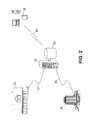
- FIG. 2depicts an iconic representation of an extended portion of an alarm system according to an embodiment of the invention.
- FIG. 3depicts a block diagram of a server portion of an alarm system according to an embodiment of the invention.
- FIG. 4depicts a block diagram of an end-user device portion of an alarm system according to an embodiment of the invention.
- FIG. 5depicts an iconic diagram of data flow pathways within a premises portion of an alarm system according to an embodiment of the invention.
- FIG. 6depicts an iconic diagram of data flow pathways throughout an extended portion of an alarm system according to an embodiment of the invention.
- FIG. 7depicts a block flow diagram of an alarm verification method according to an embodiment of the invention.
- the inventionin accordance with a typical embodiment, involves intrusion alarm systems which are verified remotely (e.g., by a user or another authorized entity, collectively “user” hereinafter for simplicity of description).
- the remotely-verified alarm solutions of the present inventionsubstantially depart from the conventional concepts and designs of the prior art.
- the inventionprovides embodiments of a system primarily developed for the purpose of visually identifying the root cause of alarm events directly and immediately, while utilizing modem high-speed Internet, phone networks, or private networks and web-enabled devices for remotely-monitoring.
- embodiments of the inventionprovide for contacting law enforcement agencies, other emergency response services, and/or any other third party designated by a user or other authorized entity, only if an alarm event is valid, and substantially or entirely without the intervention of a third party alarm monitoring company.
- An end usercan install a premise security system, and verify an alarm event regardless of the proximity of the end-user to the monitored location.
- the systemdelivers an alarm condition substantially autonomously to an end-user.
- the systemuses wired and/or wireless Internet, phone networks, private networks, and/or other communication networks to deliver to the end user an image-based indication of the cause of an alarm.
- a highly desirable feature in embodiments of the invented alarm systemis the ability to remotely and visually verify an alarm condition. False alarms can be caused in a variety of ways, including defective sensors and user error, such as failing to deactivate an alarm system upon entry. Common means for remotely verifying an actual alarm condition includes calling the premises and/or sending personnel to visit the premises from which the alarm signal originated.
- the inventionseeks to alleviate the need for such inefficient, costly, and slow means of validation by providing the premise owner the ability to interrogate the cause of an alarm over any public network, Internet, phone network, or private network.
- an automated, remotely-verified alarm systemincludes: a) an integrated Passive InfraRed (PIR) sensor (or other motion sensor) for motion detection with an integrated camera (PIRCam) or separate sensor and camera, or motion sensing camera; b) a premise Security System Media Gateway (SSMG) with storage that manages a number of PIRs, cameras, or PIRCams and transmits alarm events and associated video or static images to a remote central server; c) a hosted remote web-server (“central server”) that provides authentication, communication and data delivery to external remote end-users and law enforcement agencies; and d) remote end-user communication devices to receive telephone voice messages and/or data messages via email, instant messaging including text messaging, Systems Management Server (SMS) and/or Multimedia Messaging Service (MMS) messaging, and/or other network or web-enabled communication media.
- PIRPassive InfraRed
- SSMGSecurity System Media Gateway
- FIG. 1depicts an embodiment of a portion of a remotely-verified alarm system configured to monitor a user's premises 15 (or “premises portion”).
- one or more image capture meanssuch as cameras 2 for capturing images of portions of a monitored location.
- locationssuch as building access points, windows, hallways, rooms containing high-value items, and other locations are typically beneficially monitored for intrusion detection or other exigencies and/or emergencies.
- Cameras 2can be affixed to or at least partially within structural features of a building, such as a wall, ceiling, roof, structural support, ventilation passage, or other features. Alternatively, cameras can be provided in such landscape features as trees, shrubs, retaining walls, or other features. Wherever affixed, a camera 2 is configured so as to capture an image of an area where intrusion monitoring is desired. When numerous areas are to be monitored, cameras can be deployed in multiple locations as part of a distributed, interconnected monitoring network.
- Cameras 2 in embodimentsinclude stationary cameras, cameras capable of automatically sweeping from side to side to capture a larger area than a comparable stationary camera. Cameras can include those capable of multiple directional angles and/or directionally controllable either remotely or according to a pre-programmed scanning pattern. Cameras 2 can be configured to capture still images, full motion images (hereinafter, video), or a combination thereof, and such images will typically, but not exclusively, be either black-and-white or color images. Alternatively, cameras are used that are configured for extremely low light conditions (e.g., night vision) or for capturing viewable images of transient thermal differentials (e.g., thermal imaging) in the ambient environment.
- extremely low light conditionse.g., night vision
- transient thermal differentialse.g., thermal imaging
- Cameras 2 used in a systemmay also possess other capabilities for enhancing the informational value from captured images.
- camerascan include the ability to zoom in or out, such as to widen or narrow a field of view and increase the resolution of distant or small objects, or to compensate for changing light conditions.
- a camera 2includes a sensor capable of detecting changes in the ambient environmental conditions (hereinafter, alarm event and/or detection event), and the camera 2 is further configured to react to such changes by turning on or off, or by capturing a still image or video image (collectively, images).
- Alarm eventscan include a transient thermal (e.g., infrared, hereinafter IR) differential, a human-audible or inaudible sound, a transient reflection of a beam or signal wave emitted by the camera or another device, or other such changes.
- a sensor of a camera 2can be calibrated relative to the background (e.g., normal) conditions of the environment where the camera 2 is affixed and is to operate.
- a sensor of a camera 2such as a passive IR sensor, can be configured to specifically detect and/or indicate the presence or occurrence of an alarm event only when such changes reach and/or exceed some threshold level (hereinafter, threshold).
- a sensorcan be configured as a unitary part of a camera 2
- a sensorcan be coupled with a camera 2 either by a wire or wirelessly, and be located relatively separately from the camera 2 .
- a sensorcan include a magnetically coupled circuit affixed relative to a window or entryway such that the opening of a door or window breaks the circuit and causes the sensor to indicate a threshold alarm event to the camera 2 .
- a sensorcan include a pressure and/or tensile sensitive device (e.g., pad, plate, strip), an optical beam emitter/detector system, any of the integral sensors described above, or any other capable of detecting a threshold alarm event.
- one or more cameras 2 capable of detecting a threshold alarm event, whether having integral or separately coupled sensorsare collectively referred to hereinafter as “motion sensing cameras”, or simply “cameras”.
- cameras 2may simply be passive image gathering cameras not configured with threshold alarm event discrimination capability, but simply gather and transmit images to a signal processing device that has such capability.
- a signal processing deviceis described in more detail below.
- a camera 2has the capability to convert a captured image into an electronic and/or optical signal and to transmit the signal out from the camera 2 .
- a wireless signal transmittercould transmit a signal including a converted image via IR transmission, laser, radio, BlueTooth technology, or some other relatively local and/or line of sight signal transmission technology.
- a camera transmittercan transmit an electronic signal via a conductive wire, or to convert an electronic signal to a suitable optical signal and transmit it via optical fiber. Therefore, a transmitter of a camera may be understood, according to alternate embodiments, to be one of a wired or wireless transmitter of electronic and/or optical signals including data corresponding to a captured image.
- a transmitted signal from a camera deployed as described in a premises portion 15 of the systemis received in embodiments at a signal processing means 4 (hereinafter SSMG) configured to receive signals of the type transmitted by each of the cameras in the premises portion 15 .
- SSMG 4can be thought of as a Security System Media Gateway; and it serves as a central collection and transmission device for security systems described in embodiments of the invention.
- an SSMG 4acts as a gateway for command signals sent to cameras 2 by one or more control devices in a system embodiment, either automatically or as directed by a user.
- the SSMG 4typically is configured to and capable of monitoring, exchanging signals with, and/or controlling numerous cameras 2 .
- the SSMG 4can be configured to receive power from a primary power source, for example an external 12V DC adaptor, but may also include a secondary (e.g., backup) power source, such as one of those described above relative to cameras 2 .
- the SSMGcan be configured with status indicators for power, wireless connectivity, and alerts, although more or fewer than these may also be included.
- the SSMG 4continuously polls each camera 2 for an alarm condition over a secure wireless link, which is indicated by a change in state in, for example, a sensor device. Upon detection, the SSMG downloads an image from the camera and stores it locally.
- a signal relay devicemay be used in situations where a camera 2 is placed too far from the signal processing device 4 for consistent or effective signal transfer.
- a camera 2can transmit a wireless signal 3 to an intermediately located relay device, which then transmits the signal by wire to the signal processing device 4 .
- an embodimentcan include the camera 2 and the SSMG 4 integrated as a relatively unitary device, wherein signal transmission between the camera 2 and the SSMG 4 occurs internally within the integrated device.
- Storage means 12can be an integrated or peripheral hard disc drive, a memory chip or chip device (e.g., dual in-line memory module, DIMM or integrated memory within a micro processor), fixed or removable memory of any known format (e.g., RAM, flash, compact flash), an optical storage media device (e.g., DVD, CD), or some other mass storage device or combination of devices as known to those having skill in the art as the embodiments are not so limited.
- a memory chip or chip devicee.g., dual in-line memory module, DIMM or integrated memory within a micro processor
- fixed or removable memoryof any known format (e.g., RAM, flash, compact flash), an optical storage media device (e.g., DVD, CD), or some other mass storage device or combination of devices as known to those having skill in the art as the embodiments are not so limited.
- the SSMG 4is configured to include the functions and capabilities of a digital video recorder (DVR), either integrally within the SSMG 4 or as a peripheral component controllably coupled with the SSMG 4 .
- DVRdigital video recorder
- the SSMG 4will typically, but not always, be coupled with other components within the premises 15 .
- a signal transmitting means 6e.g., router, modem, cable converter box, computer
- the signal transmitting means 6will further include a continuous and/or non-continuous connection, by wire 7 and/or wirelessly, to elements of the system external to the premises 15 .
- the functions of a signal transmitting means 6can be integrated into the SSMG 4 , thus eliminating the need for a peripheral signal transmitting means 6 .
- Signal transmitting means 6is configured to transmit a signal including data corresponding to one or more images, by at least one of the numerous transmission means and/or technologies currently available.
- Such transmission means and/or technologiescan include any one or more of cable broadband, DSL, WAN, WiMAX, Wi-Fi, cellular phone signal, satellite, and/or others as known in the art.
- the SSMG 4can be further coupled with a data input and/or computing means 9 , such as a computer (hereinafter “local computer”)(e.g., desktop computer, portable computer) or similar device.
- local computer 9is configured, according to alternative embodiments, to perform one or more of receiving, processing, storing, and/or conveying to the SSMG 4 at least a first set of configuration parameters.
- Configuration parameterscan include any one or more of camera control parameters (e.g.
- the local computer 9can also be preconfigured with configuration parameters including contact information and/or communication method selection for connecting with a central server upon the occurrence of an alarm event, with a remote end-user device, and contact information for emergency response services and/or agencies.
- the local computer 9can be configured to be a DVR device, rather than the SSMG 4 in an embodiment, including capacity and means for storage, retrieval, and/or viewing of images.
- DVR capabilitiescan be configured at least in part as software instructions fixed in a tangible medium, such as a hard disc drive medium or an optical storage medium.
- the local computer 9is coupled in communication with the SSMG 4 by a wire 8 according to an embodiment, but could alternatively be coupled wirelessly.
- a “wire” as referred to throughout this descriptionincludes any tangible signal conveying means embodied as hardware (i.e., not air), such as an optical fiber or bundle, or an electrically conductive wire or cable, and is not limited to any one particular form.
- the local computer 9typically includes a storage means for storing at least one or more configuration parameters, captured images, or other data related to system functions.
- a local computer 9typically also includes a peripheral input device (e.g., mouse, keyboard), a display device (e.g., monitor), and/or an output device (e.g., printer), although one or more of these may be omitted in some configurations. Further, embodiments of a local computer 9 can also include an integrated signal transmitting means 6 , obviating the need for a stand-alone signal transmitting means 6 or a signal transmitting means 6 integrated with the SSMG 4 .
- a peripheral input devicee.g., mouse, keyboard
- a display devicee.g., monitor
- an output devicee.g., printer
- the local computer 9typically exists separately from the SSMG, a particularly integrated embodiment of the SSMG 4 can incorporate one or more of the features, devices, or functions of the local computer 9 , or can even obviate the need for a separate local computer 9 .
- the functions and/or structural features of an SSMG 4can be integrated into a local computer 9 .
- the local computercan instead be a remote computer located remotely from the premises, yet performing all or substantially all of the functions as described herein, such as by communicating with the SSMG 4 over a public or private network.
- a systemcan include a portable, wireless signal transmitting means 11 configured to transmit a wireless signal 10 for remotely altering the activation status of the system.
- a portable, wireless signal transmitter 11can be configured as a key chain device (e.g., key fob) or other remote control device.
- a portable, wireless signal transmitter 11can be integrated into another electronic device.
- the portable, wireless signal transmitter 11will be configured for relatively short range transmission, but is not necessarily so limited, and can provide for control even at extended distances.
- the portable, wireless signal transmitter 11will generally include an integral power supply, such as a replaceable or rechargeable battery, to enable portability.
- the portable, wireless signal transmitter 11can be used to activate and/or deactivate the alarm system, and/or lock or unlock a door, and may include functions for otherwise altering at least a first set of configuration parameters of an embodiment of a remotely-verified alarm system.
- a wireless transceiverwill be included in the SSMG 4 to receive and/or exchange signals with the portable, wireless signal transmitter 11 , enabling the SSMG 4 to affect changes to the alarm system in response to the signals.
- Elements of the premises portion 15will generally be powered by an existing electrical power system present at the monitored location (e.g., a residence, business office).
- the electrical power systemcan be intentionally and/or accidentally interrupted. Therefore, embodiments of the premises portion of a self-monitored alarm system include a back-up power source to provide substantially continuous alarm system operation despite the interruption of a primary electrical system.
- a back-up systemcan include at least one of a solar energy power source, a power generator (e.g., gasoline powered), a commercial uninterruptible power supply (UPS), a battery system, or other power source.
- the premises portion 15comprises only a portion of embodiments of the invention.
- the monitored premises 20and the premises portion 15 ) is coupled in communication with a central server 22 (server).
- the central server 22typically includes both hardware and software components, and is hosted at an off-site location relative to the user's monitored premises 20 . It provides, among other functions, premise and end-user authentication and/or authorization, storage of preconfigured settings, and communication capabilities including but not limited to email, IP, SMS messaging, MMS messaging, and telephone text-to-speech communication, to communicate with both the remote end-user device 25 and emergency response services 27 .
- the central server 22also archives alarm events and associated video or images and makes those available for remote end-user viewing from, for example, a standard web-browser utility.
- premises 20is coupled with the server 22 by a signal conveying means 21 (e.g., optical, electrically conductive) in some embodiments, while in others, the communicative coupling is partially or entirely wireless.
- the signal conveying means 21is generally part of a public network, Internet, phone network, or private network, but is not so limited.
- the central server 22can be a hosted web-server, and will generally be monitored, either locally or remotely, by a human attendant. However, it can also perform many if not all of its alarm system functions according to pre-configured parameters, settings and/or programs without substantial human intervention.
- a server 22is also coupled with a data storage means 23 in embodiments.
- the data storage means 23enables storage and retrieval of data corresponding to images transmitted from the premise 20 to the server 22 . It can also retain predetermined configuration parameters and/or instructions relating to individual end users, premises 20 , emergency response services 27 , and/or other detection and alarm activation relevant data. Therefore, storage of image data is not necessarily required at the premises portion 15 in all embodiments, simplifying the components and functions present at the premises portion 15 of the alarm system.
- server 22comprises a relatively unitary network service device, as depicted in FIG. 2
- server 22is broadly contemplated as an collection of functional modules, structurally embodied, and collectively considered a “server portion”.
- the server portion 30is represented as a block diagram including numerous structural and/or functional modules, one or more of which is coupled with a data storage module 29 and with at least another module.
- Signal conveying means 21 from the premisesis coupled with a Detection.
- Signal Receiving Module 31DSR module of the server portion 30 .
- the DSR module 31can include structural elements, for example an antenna or a cable connection structure.
- the DSR module 31can also include discriminating elements (e.g.
- the DSR module 31can subsequently alter the signal by adding data to the signal and can convey the signal to a Detection Signal Routing Module 32 (routing module), or can convey the signal to the routing module substantially unchanged.
- the routing module 32receives the signal, and evaluates characteristics of the signal as defined by data included in the signal.
- the signalcan include data identifying a unique user, and/or image data that can be compared to baseline image data stored in data storage module 29 to identify anomalies relative to the baseline image data.
- the routing module 32can then utilize the identification and/or other data to retrieve unique transmission parameters from data storage module 29 , the transmission parameters providing instructions and/or information needed for transmitting a signal to the appropriate end user including at least the image data.
- the necessary transmission parameterscan be included in the signal as transmitted from the premises 20 and received at the DSR module 31 .
- the routing module 32subsequently conveys the transmission parameters and the received images to a Detection Signal Transmission Module 33 (transmission module).
- the transmission module 33reads and recognizes the transmission parameters and transmits a signal 24 a including the images to an end user device 25 depicted in FIG. 2 .
- timing module 34Signal Interval Timing Module 34
- transmission of the signal 24 a to the end user device 25is recognized by a Signal Interval Timing Module 34 (timing module), and identified as to both the user and the specific signal 24 a .
- Thisis possible, in embodiments, due to the signal 24 a including associated data uniquely identifying the user and the transmitted signal, such as by date- and/or time-related data, or a unique code generated specifically for each signal transmission.
- the timing module 34begins monitoring the duration of time between the transmission of the signal 24 a from the transmission module 33 to the user, and the return of an alarm verification signal 24 b from the user device 25 .
- the timing module 34can be implemented at least in part as software, and can include either integral time-keeping components, or can track time according to a timing system maintained by a third party (e.g., The National Institute of Standards and Technology).
- the transmitted signal 24 acan take the form of any of a plurality of available communication methods, including but not limited to network messages, email, SMS messaging, MMS messaging, text-to-speech communication or another as known or may be provided in the art. Further, the signal can be transmitted by or as any one of GSM cell phone signal, GPRS, WiMax network or another communication format or infrastructure, as are known or may be provided in the art.
- the verification signalWhen the user device transmits a verification signal 24 b , and provided the user device is within reception range, the verification signal is received at a Verification Signal Receiving Module 35 (VSR module) of the server portion 30 .
- VSR moduleVerification Signal Receiving Module
- the verification signal 24 bwhich typically will not include image data, but will include data corresponding to at least a portion of the unique identifying data associated with signal 24 a , is then conveyed from the VSR module 35 to a Verification Confirmation Module 36 (VC module).
- the VC modulerecognizes the unique identifying data, and instructs the timing module 34 to cease monitoring the elapsed time since transmission of signal 24 a.
- the VC modulethen identifies data associated with the verification signal 24 b to determine a user specified alarm status. If the user specified a status verifying that the alarm is valid, then the VC module 36 will notify a Host 38 of the server portion 30 to report an alarm to a public and/or private Emergency Response Service 27 (see FIG. 2 ) via an Alarm Transmitter 37 . However, if the user specified a status verifying that the alarm is invalid (e.g., a false alarm), then the VC module will notify the host 38 of the server portion that the alarm is invalid, and therefore does not warrant contacting the emergency response service 27 . It is contemplated that in embodiments, rather than contacting an established Emergency Response Service or agency, some other third party (e.g. a neighbor, a friend, and employee) is contacted by the Alarm Transmitter 37 . However, for simplicity of description and without intending any narrowing by the term, the various embodiments are broadly referred to herein as an Emergency Response Service 27 .
- the alarm transmitter 27can be a telephone, a radio system, a network message connection, an internet connection, or nearly any other device or system permissible and capable within a particular area for contacting emergency response organizations.
- local and/or state lawsmay require that any call to public emergency response services via the 9-1-1 system must be made by a human, and not automated to operate without human intervention. Therefore, the host 38 is typically human.
- embodiments of the inventionare not so limited, and could provide for an automated alarm transmission to, for example a privately contracted security company or a neighbor near the monitored premise 20 .
- the host 38can be a decision-making module capable of evaluating input data and executing an action based upon predetermined contact parameters and/or instructions, or the VC module 36 can itself cause the alarm transmitter 37 to transmit an to the emergency response service 27 .
- the host 38may be embodied at least partially as software capable of evaluating data input from a verification signal 24 b , determining an appropriate response according to predetermined instructions, and as output, affecting the appropriate response, such as causing an alarm transmitter 37 to transmit a valid alarm.
- an alarm transmitted from the server portion 30 to a emergency response service 27is transmitted according to a set of predetermined contact parameters (e.g., radio frequency, telephone number, email address) and/or other instructions.
- a set of predetermined contact parameterse.g., radio frequency, telephone number, email address
- Such parameters and/or instructionsprovide that the relevant and/or necessary information is conveyed to the appropriate services 27 (e.g., closest to the monitored premise 20 , appropriate to the type of alarm event) and/or consolidated dispatch center to respond to the alarm event, and may also include additional content and value.
- the server portion 30may not receive a verification signal from the user for an extended period of time.
- the usermay be out of signal transmission range, or the user's device may be malfunctioning, deactivated, or left behind by the user.
- the timing module 34can, as part of the configuration parameters associated with a user, determine the expiration of an allotted duration of time without receipt of a verification signal 24 b . Upon such expiration, the timing module 34 notifies the VC module 30 of the expiration, and conveys to the VC module 30 data associated with the unacknowledged signal 24 a (including the user identification data).
- the VC module 30then retrieves instructions and/or other configuration parameters from the data storage module 29 .
- the VC module 30notifies the host 38 which then contacts the premises via a transmission means.
- the VC module 30will, in an embodiment, cause a telephone call to be placed to the premises 20 . If the telephone call is not answered by the premises 20 , or alternatively, if the call is answered but the answering party fails to correctly provide and/or authenticate a pre-configured password or some other security code, the VC module 30 of the server portion 30 will notify the host 38 that conditions exist for transmitting an alarm signal to an emergency response service 27 via the alarm transmitter 37 .
- a usercan provide predetermined instructions directing the server portion 30 to transmit an alarm signal to an emergency response service 27 without first attempting to contact the premises 20 .
- the server portion 30includes an Image Data Analysis Module 39 (analysis module).
- a server portion 30 including this moduleallows a user to specify conditions for transmitting a valid alarm based upon characteristics of a captured image. For example, an alarm event detection signal is received at the DSR 31 and is conveyed to the routing module 32 .
- the routing module 32recognizes configuration data associated with the signal, checks the data storage module 29 for instructions relating to user and/or premises identifying data associated with the signal, and in accordance with predetermined instructions, conveys the signal to the analysis module 39 rather than (or in addition to) the transmission module 33 .
- the analysis module 39includes, in embodiments, video analytics means (e.g., image analysis software) configured to analyze data in the signal corresponding to captured image data (e.g., static images, video). Further, the analysis module 39 is configured to discriminate based at least in part on the content of image data and predetermined configuration parameters. If the video analytics means identify image data representing a human presence and/or other behavior, and if so indicated according to predetermined alarm parameters, the analysis module 39 conveys a signal to the VC module 36 confirming a valid alarm. Therefore, the VC module 36 will notify the host 38 , and a valid alarm signal is transmitted to an emergency response service 27 .
- video analytics meanse.g., image analysis software
- the analysis module 39can either convey a signal to the VC module 36 confirming an invalid alarm, or can return the signal to the routing module 32 with associated data indicating an inconclusive video analysis. In the latter situation, if instructions in the data storage module 29 so indicate, the VC module 32 will then convey the signal to the transmission module 33 for transmission to the user for verification.
- an additional level of automation and image-based alarm verificationis provided to help reduce the number of false alarms, while still providing the option for subjective user review.
- Such embodimentsconstitute an intelligent burglar alarm system embodiment of a remotely-verified alarm system.
- modules included in the server portion 30are configured for processing data associated with a signal and/or accessing and acting upon predetermined instructions.
- instructionsare generally stored in and accessed at a data storage module 29 (a central data storage means in embodiments)
- other embodimentsinclude dedicated data storage means associated with one or more of the modules of the server portion 30 .
- Such dedicated data storage meanswill typically, but not exclusively, constitute a sub-portion of a particular module, and may store instructions particular to the operations of that module.
- a dedicated storage meanscan be shared by two or more modules, although being an integral part of one module, or even existing as a separate storage module in addition of storage module 29 .
- storage module 29can be designated for image data storage only, while one or more other data storage modules of the server portion 30 are designated for retaining instructions and other information. Therefore, a server portion 30 can include more than one storage means and/or more than one storage module, and each of a plurality of data storage means and/or modules can be designated to fulfill either redundant and/or different purposes relative to at least another data storage means and/or module.
- Each module in the server portiongenerally includes structural elements, such as electronic components, configured and coupled with and/or relative to each other so as to meet the functional purpose(s) of the module. Further, each module is configured and coupled with and/or relative to at least another module of the server portion so as to meet the functional purposes of the server portion 30 .
- a server portion 30can be embodied as a single device, such as a web server, the embodiments are not so limited.
- a storage module 29can comprise a device separate from but communicatively coupled with one or more other devices, with the plurality of devices comprising the server portion 30 .
- the server portionneed not be comprised entirely as devices, but can include a human element as, for example a host 38 .
- the operations of the server portion modulesgenerally operate at least in part based upon pre-determined instructions provided by a user. Instructions are predetermined, throughout this description, inasmuch as they are provided at least in part by the user at a time prior to the operation of the module upon a particular signal.
- a signal arriving at a module from another module, a premises, or a user devicemay include associated instructions.
- the instructionsarrive at the module at the same time as a signal, they were provided by the user at or prior to the time the signal was transmitted to the module and so are predetermined instructions.
- At least one module of a server portion 30also includes logic capability, and/or comprises a software component.
- a modulemay be entirely or substantially configured as software embodied in a tangible medium and configured to be executed by a computing device. As a result of such execution, the software can cause, for example, a transmitting module 33 or alarm module 37 to transmit a signal.
- server portion 30of an alarm system
- any two or more modulescan be embodied as a single integrated module configured to perform the described functions of the integrated modules.
- server portioncan be embodied as several physically distinct but functionally and communicatively coupled devices. Therefore, the term “server” used herein can refer to a single computing device embodying part or all of the server portion, or can refer to the server portion 30 generally.
- the server 22is typically but not exclusively coupled in communication with an end-user (user) device 25 .
- the conveying means 24will generally, but not exclusively, include wired and/or wireless communication network infrastructure including public and/or private receivers, transmitters, signal boosters, relays, and/or other wired and/or wireless signal conveyance infrastructure (e.g., hardware, facilities, devices). Indeed, such infrastructure can comprise all or part of any of the wired and/or wireless signal pathways set forth in this description.
- a user devicecan include, but certainly is not limited to, any portable electronic device such as a mobile telephone, a web-enabled personal digital assistant (PDA), a relatively stationary and/or mobile computer (e.g., desktop, notebook, tablet, palmtop), or an electronic communications device integrated within an automobile.
- PDApersonal digital assistant
- a user deviceis any electronic device(s) capable, either individually or when combined, of receiving a signal including data corresponding to at least one image, displaying the image to the user, and transmitting a signal including a remotely-verified response to an alarm event.
- end user device 25typically (but not exclusively) comprises a unitary device, it may be more clearly understood as a collection of structurally-embodied functional modules, collectively referred to as an “end-user device portion”.
- FIG. 4depicts an embodiment of a user device portion 40 of an alarm system including numerous structural and functional modules, although more or fewer modules may exist in alternate embodiments having greater or lesser levels of integration.
- An alarm detection signal 24 a transmitted from the server portion 30is received at a Detection Signal Receiving Module 41 (DSR).
- the DSR 41is typically, but not exclusively, embodied as a wired or wireless network connection, of which many forms are known in the art and can be used according to embodiments.
- the DSR 41can be internal or external to the device, can be fixed or extensible (e.g., a telescoping antenna structure), and can be configured for efficiently receiving one or more of various signal formats that may be transmitted from the server portion 30 .
- a DSR 41can also include electronic, optical, and/or optoelectronic components configured for receiving, amplifying, converting, transforming, or otherwise acquiring a transmitted signal. Therefore, the embodiments of a wired or wireless network connection as conceived herein are expansive rather than limited.
- the processing module 42typically includes a processing means, such as a microprocessor device, a graphics generator, and/or another integrated circuit device. Further, a processing module 42 can include or be coupled in communication with a data storage means, such as a hard disc drive, a memory chip or chip device (e.g., dual in-line memory module, or DIMM), or a removable memory card of any known format (e.g., compact flash), although the embodiments are not so limited.
- the memory meansincludes instructions which, when operated upon by the processing module 42 , recognize data in the signal and cause the device to notify the user of the alarm.
- Notificationcan include the device emitting an audible signal that the user can perceive, or can include a substantially silent signal, such as displaying a message indicating receipt of an alarm, or causing a vibration generating device within the user device 40 to generate a user-perceptible vibration.
- a vibration generating devicewithin the user device 40 to generate a user-perceptible vibration.
- the useris able to select from the available modes.
- the processing module 42also identifies image data in a received signal 24 a , and stores the data in the user device portion 40 for later access and viewing by the user.
- the image datacan be included in a file attached to an email message, or accessible via an included link, or otherwise associated with the signal.
- the processing module 42will convey the image data, whether altered or unaltered, to an Image Data Display Module 43 (display) capable of converting the image data into an image that is viewable by the user.
- the signal 24 acan include a link or other information enabling and/or directing the end user to access a hosted website to obtain image data and alarm condition information.
- the user devicemay include a data storage means containing pre-determined contact information for contacting a hosted web-site or another image data-storage and transmission service and/or device.
- the hosted websiteWhen accessing the hosted website, the user can view stored images at or accessible through the website.
- the usercan access the SSMG 4 via the website and view real-time images from one or more of the cameras 2 monitoring the premises 20 .
- the hosted website described hereinwill typically, but not exclusively, be located at the server portion 30 .
- the display 43can include processing means to convert and otherwise modify image data into a viewable form independently from the processing module 42 , or can simply receive and display image data as a viewable image without otherwise transforming the data.
- the display 43can also share processing means with the processing module 42 , the DSR 41 , or both.
- a display 43generally also comprises any of a number of image display means.
- a display 43can include an LCD display, a plasma display, or a CRT display.
- a display 43is virtually any image display technology currently known or reasonably contemplated that can be integrated into a portable user device 40 , or with which a portable user device 40 can be operatively coupled. In the latter situation, a display 43 of a user device 40 need not be permanently coupled with the user device 40 , but can exist separately and be considered a part of the user device 40 when coupled thereto.
- a user device 40further includes an Alarm Verification Module 44 .
- the verification module 44provides a means for a user to control how an image is displayed, whether the image is a static image, a full-motion video image, or some other form. Control parameters can include start, stop, advance, reverse, zoom, contrast, color, tone, or other such useful playback and/or image modification capabilities as would be understood by those having skill in the art. Further, the verification module 44 provides a means for the user to indicate the status and/or disposition of an alarm signal. For example, if the user determines that the image depicts conditions requiring an emergency response (e.g., unauthorized intrusion, fire, medical emergency), the user can indicate that the alarm is valid, and select an appropriate response method via the verification module 44 . Conversely, if the image depicts conditions requiring no response, the user can indicate that the alarm signal is invalid, and that no response or a lesser response is appropriate.
- an emergency responsee.g., unauthorized intrusion, fire, medical emergency
- the verification module 44includes, in embodiments, processing means, which can be dedicated or can be shared with one or more of the other modules.
- the verification module 44can also be coupled with data storage means and can access and operate upon data and/or instructions stored therein. Therefore, the verification module 44 can present a graphic user interface (GUI) at the display 43 , visually providing a clear and user-friendly interface for selecting an alarm status, for controlling the display of an image, or for selecting and/or altering any other configuration parameter.
- GUIgraphic user interface
- a usercan, by interacting with a GUI, respond to an alarm notification by causing an image to appear on the display 43 .
- the usercan, again using the GUI, select to respond to the alarm, whereupon the GUI changes to present a set of options to the user.
- the usercan then select an option (e.g., “Alarm Valid”), causing another GUI to appear and provide options for an appropriate response (e.g., “Contact 9-1-1”).
- another GUIcan appear, and the user can select an option causing the device to transmit a signal 24 b including the user-selected alarm verification status to the server portion 30 .
- GUIsWhile the embodiment described above includes various user-input methods implemented as GUIs, the embodiments are not so limited, nor are the format or content of the described GUIs.
- a GUI-implemented alarm validation interfacecan be as simple as one or more icons presented at the display of the device that the user selects to indicate an alarm validation status.
- the user device 40includes a user input module 45 such as a key pad, a touch screen, a touch-sensitive pad, or another input modes and/or device as known to those skilled in the art. Therefore, the input module 45 can include a physical input device, or can alternatively include a GUI as described above with regard to the verification module 44 . The input module 45 and the verification module 44 can also functionally interact. For example, when a user inputs a response using a key pad in response to a message presented via a GUI, the user's response causes the GUI to change and present a new set of options to the user, the new options based at least in part on which option the user selected.
- a user inputs a response using a key pad in response to a message presented via a GUIthe user's response causes the GUI to change and present a new set of options to the user, the new options based at least in part on which option the user selected.
- User input module 45can be a part of another device, (e.g. a cell phone, a PDA, a computer).
- the user input module 45in embodiments, also includes processing means as described relative to other of the modules, and/or is coupled in communication with data storage means to access and operate upon, or in response to, stored instructions.
- a Verification Signal Transmission Module 46of the user device 40 transmits a signal 24 b to the server portion 30 including at least data indicating the user selected verification status.
- the VST 46includes a signal transmitter, which can transmit via one of a wireless or a wire-conveyed signal.
- the transmission module 46includes, in embodiments, processing means as described relative to other embodiments, and/or is coupled in communication with data storage means, for accessing stored signal relevant data and/or for acting upon or according to stored instructions. For example, acting according to transmission parameter instructions can cause the transmission module 46 to convert an electronic digital signal into an optical signal for transmission via an optical signal conveying means (e.g. optical fiber).
- an optical signal conveying meanse.g. optical fiber
- the transmission means, technology, and/or message format (collectively “format”) of the transmitted verification signal 24 bcan be the same as that of the detection signal 24 a , or it can be different according to alternative embodiments.
- a signal formatcan include messages sent via email, IP, web-link, SMS messaging, MMS messaging, or voice activated or touch-tone dialing. Therefore, the VST 46 is configured to transmit a signal according to a particular transmission format as described above, or can be configured to transmit via more than one format. Generally, the VST 46 transmits in a format which can be received and properly (e.g., correctly, effectively) interpreted at the server portion.
- the transmitted verification signal 24 bwill generally also include data identifying the user and/or will include all or some portion of a unique signal identifying code transmitted from the server portion 30 to the user device 40 .
- the usermay be required to enter a password or other unique identification code when responding to an alarm.
- the password or other codeis included in the transmitted verification signal 24 b to notify the server portion 30 that the user is authorized to respond relative to the alarm.
- the usercan also, via the user device 40 , initiate a transmission to the server portion 30 and/or the premises portion 15 .
- the usermay wish to view the status of a portion of the monitored premises. Therefore, the user can interactively transmit commands to the premises portion 15 causing one or more cameras to capture images, and/or causing the SSMG 4 to transmit images to the user device. 25 for viewing at the display module 43 .
- Such imagescan be captured and stored for later viewing, or can be viewed in substantially real time, subject only to signal transmission and/or processing latencies.
- the usermay wish to alter configuration parameters and/or alter the operational status of the alarm system.
- the userinitiates via the user device 25 either a one-way transmission or an interactive session with the premises portion 15 , sending data including commands to affect such alterations, and perhaps receive confirmation data in return.
- the usercan remotely alter configuration parameters stored at the server portion 30 in a similar fashion. In either situation, the user can transmit a password and/or unique identification code to confirm that the user is authorized to affect the indicated actions.
- the server portion 30upon receiving verification of a valid alarm from a user, or alternatively upon expiration of a pre-determined duration of time without receiving a response from the user, the server portion 30 transmits a signal to an emergency response service 27 .
- the signalcan be transmitted either wirelessly or by a wire 26 , and can utilize any of numerous transmission formats and/or communication means. Additionally, such transmission means may include voice communications as a viable method in embodiments.
- the emergency response service 27will also possess signal receiving means, such as web-enabled devices, mobile computers with wireless capabilities, servers, or means capable of receiving and processing an alarm signal. Additionally, such receiving means may include voice communications.
- the transmitted signalcan include a pre-configured message, configured for example at least in part by the end user, the server portion 30 (e.g., a host 38 ), or the emergency response service 27 .
- the messagecan include information to direct a particular response, to identify the location of the monitored premises, to indicate the nature of the detected alarm and/or emergency, and/or other information useful to an emergency response service to affect a rapid and appropriate response (e.g., sending the fire department in response to a fire).
- the server portion 30will also, in embodiments, transmit as part of the initial signal and/or as a separate signal, data corresponding to captured images.
- a respondercan, in an embodiment, view the images at a display device, and can therefore better understand the nature of the alarm condition. For example, if the images depict an armed intruder, the responder at the emergency response service can dispatch a SWAT team to the monitored premises, and can further cause evacuation of the surrounding area.
- the emergency response servicecan include, in embodiments, mobile emergency response service vehicles and/or personnel
- the server portioncan transmit validated alarm signals and images directly to mobile responders. This capability provides unique capabilities for efficiently, appropriately, and effectively responding to an alarm at a monitored premises, and managing such response.
- a userwhile transmitting signals including instructions to cause the premises portion 15 to capture and transmit real-time images, can further cause the real-time images to be transmitted through the server portion 30 to the emergency response service 27 .
- Thisprovides real-time image-based monitoring of the monitored premises 20 by the emergency response service 27 before, during, and/or after a response to an alarm.
- FIGS. 5 and 6provide an overview of data flow pathways in the premises portion and the extended alarm system, respectively, that occur in embodiments of the invention. Although not every function or embodiment involves signals traversing every possible data flow pathway, the pathways are depicted in a relatively consolidated form for simplicity.
- signals transmitted from a camera 2 to SSMG 4follow pathway 51 a . These signals typically include captured images. Conversely, signals from the SSMG 4 to a camera 2 traverse pathway 51 b , and may include instructions for controlling a camera.
- the SSMG 4may then transmit a signal to, for example a router 6 along pathway 52 a for subsequent transmission by, for example router 6 to a server 22 (see FIG. 2 ).
- Signals received from a server portion 30 and/or a user device 25will traverse pathway 52 b , in embodiments, from the router 6 to the SSMG 4 .
- these pathwayslikewise occur internally within the SSMG 4 .
- Pathway 53 a from the SSMG 4 to the local computer 9can convey data corresponding to images for storage at a storage means of the local computer 9 .
- Pathway 53 b 4typically conveys one or more stored configuration parameters from the local computer 9 to the SSMG, among other data types.
- Pathway 54 aconveys, among other things, images from the SSMG 4 to a data storage means 12
- pathway 54 bconveys data from the storage means 12 back to the SSMG 4 , such as to provide the user the ability to review stored images.
- Pathways 55 a and 55 bconvey data between the router 6 and the local computer 9 , and as described above relative to the SSMG 4 , when router 6 is integrated within the local computer 9 , or the SSMG 4 itself, according to an embodiment, pathways 55 a and 55 b exist within the local computer 9 , or alternatively are integrated within the SSMG 4 .
- Each of pathways 55 a and 55 bcan typically, but not exclusively, convey transmission parameters and/or images, but are not so limited.
- Pathway 56 aconveys a signal from a portable, wireless signal transmitter 11 to the SSMG 4 , such as to alter an alarm system activation status.
- a signal conveyed from SSMG 4 to the portable transmitter 11 along pathway 56 bcan confirm an activation status of the alarm system, and through a logic circuit and/or device within the transmitter 11 , cause an LED on the transmitter 11 to illuminate.
- the depicted pathways of the premises portion 15 in FIG. 5are not, however, exclusive, and additional and/or alternate pathways are included within the scope of the invention according to alternate embodiments.
- Such embodimentsmay include integration of elements within the premises portion.
- the local computer 9 and the SSMG 4may be integrated in an embodiment, and the signal pathways 53 a and 53 b may take place entirely within the integrated device. Further, depending upon the configuration of the integrated device, pathways 53 a and 53 b may not exist in a separate and significant form.
- Other elements and/or devices within the premises portion 15may likewise be integrated, or additional elements may indicate the presence of additional pathways.
- an added peripheral devicee.g., printer
- data storage means 12could be coupled in communication with data storage means 12 , and signal pathways would exist between them for conveying data for storage and/or retrieval, according to an embodiment. Therefore, the signal pathways depicted in FIG. 5 are for illustrative purposes, and are not intended to limit the scope of embodiments of the invention.
- signal pathway 61conveys signals from the monitored premises 20 (and premises portion 15 ) to a central server 22 , for example in response to an intrusion detection, and pathway 62 conveys signals from the server 22 to the premises 20 , such as when the end user wishes to control a camera 2 to obtain a real-time image.
- Pathways 63 and 64convey signals between the server 22 and an end user device 25 , such as detection signal 24 a and verification signal 24 b , respectively.
- Pathway 65conveys signals from the server 22 to the emergency response service 27 , as when reporting a verified valid alarm.
- Pathway 66in an embodiment, conveys a confirmation signal from the emergency response service 27 to the server 22 , confirming that the alarm signal has been received.
- the alarm systemcaptures image data and transmits a first signal to the SSMG.
- the SSMGreceives the first signal, and transmits a second signal to a server portion, at 72 , and then at 73 , the server portion receives the second signal, and transmits a third signal to a device of the end user.
- the end user devicereceives the third signal, and at 74 , the user views image data of the third signal at a display of the end user device.
- the end userinputs validation data (e.g., “Valid Alarm”, “Invalid Alarm”), and transmits a fourth signal from the end user device to the server portion.
- validation datae.g., “Valid Alarm”, “Invalid Alarm”
- the server portionreceives the fourth signal, and if the fourth signal includes data indicating that the alarm is valid, the server portion transmits an alarm signal to an emergency response service.
- image datais stored, as shown at 77 .
- signalsare transmitted, modified, augmented, processed, and otherwise handled according to configuration parameters, at least a subset of which, and generally most of which, are predetermined, for example by the end user.
- configuration parametersare determined relatively contemporaneously with the receipt or transmission of signals, as determined by data associated with the signal and/or other predetermined configurations parameters.
- An end user device 25is typically maintained in the possession of the end user, and therefore it is the end user who receives and verifies the validity of detected alarm events.
- the end useris unable to receive transmitted signals from the server portion 30 (e.g., out of transmission range) or it is otherwise inconvenient or impossible for the user to receive and/or verify alarm events. Therefore, the user can designate an alternate trusted entity to receive and verify detected alarm events, and the trusted entity will be considered a user according to the embodiments described and contemplated herein.
- a trusted entitycan be a friend, a family member, an agent or employee, or a commercial service, although the embodiments are not so limited, and can include nearly anyone designated by the user and/or another authorized entity.
- a user device 25includes whatever device a user employs to carry out the functions of a user device 25 as described above.
- a useror a trusted entity as user
- signals 24 a and 24 bcan be exchanged with (e.g., transmitted to, received from) the trusted entity's user device 25 by wire (as broadly described above).
- the user device 25is not limited to being a portable, wireless device (e.g., PDA, mobile telephone), but can also be a personal or desktop computer or any other device operably coupled, whether persistently or intermittently, in communication with a server 22 or with at least one module of server portion 30 .
- a portable, wireless devicee.g., PDA, mobile telephone
- the user device 25can also be a personal or desktop computer or any other device operably coupled, whether persistently or intermittently, in communication with a server 22 or with at least one module of server portion 30 .
- An alarm systemcan include more than one level of user permissions (e.g., authority, access, control), and a trusted entity may not be given all the same levels of control of an alarm system permitted to an end user.
- a trusted entitymay not, according to a level of authority granted by the end user, be able to alter some or all of the configuration parameters of an alarm system, such as altering passwords or accessing stored image data. Therefore, while providing a proxy “end user” to verify the validity of detected alarms, an end user can retain control over at least some aspects of system configuration and/or function.
- signals transmitted between a premises portion 15 , a server portion 30 , an end user device 15 , and an emergency response service 27can be conveyed according to any one of or combination of communication structures.
- any of the signals described hereincan be transmitted either wirelessly or by a wired connection according to embodiments, and no limitation to either one or the other is intended herein. Therefore, symbols used in the figures to represent signal conveying means 21 and 24 in FIG. 2 , for example, are not intended to limit either signal conveying means as being wire or wireless. The depicted symbols could just as easily and accurately be transposed in the figures to represent alternative contemplated embodiments.
- wireless communication structurescan include commercial cellular telephone networks, Wi-Fi and/or WiMAX networks, satellite communication networks, publicly available radio frequencies, or proprietary (e.g., military, industrial) wireless communication networks, although the embodiments are not so limited.
- wired communication structurescan include fiber optic networks, cable (e.g., cable television and broadband) networks, telephone networks (e.g., PSTN and DSL), and others capable of carrying a communication signal.
- any one or more of the signals transmitted within embodiments of the systemcan be transmitted in a secured manner, by use of, for example, data and/or signal encryption, frequency modulation, coded ciphers, or any other method and/or means available for use with public and/or private signal transmission devices, networks, protocols, or communication formats.
- the present inventionprovides a self-monitored alarm verification solution for visually identifying the root cause of alarm events, relatively directly and immediately, while utilizing modern high-speed Internet, phone networks, or private networks and web-enabled devices for self-monitoring. It also provides a self-monitored alarm verification solution that will visually record an alarm event at a premise location utilizing any combination of a camera (PIRCam) or separate PIR or other sensor and separate camera, or motion-sensing camera to make available images of the alarm events to be validated remotely by the end-user.
- PIRCama camera
- separate PIR or other sensor and separate cameraor motion-sensing camera
- the described systemincludes an alternate power source in case a primary power source is interrupted, and also includes alternate power sources for remotely located image capture devices providing a high degree of flexibility in their placement and configuration.
- Embodimentsinclude either and/or both of wired or wireless signal transmission, and are modular enough and simply enough to use that they can be installed either by a professional installer or by an end user and/or premise owner.
- Embodiments of the systemcapture and temporarily store alarm event images, and also securely transmit said images to an off-site location where they can be retrieved and viewed by an end user utilizing any web-enabled device. Further, embodiments of the invented system enable tremendous variability and flexibility to utilize communication, transmission, and data formats, devices, and/or modes, as would be most useful, reliable, affordable, and available in the situation of each particular end user. For example, the described system can interface with and communicate over any public network, Internet, phone network, or private network, although other networks may also be alternatively utilized.
- the systemcan be enabled (“armed”) and disabled (“disarmed”) remotely or within the premise via either the use of the SSMG, a local PC connected to the SSMG or by a wireless transmitter key fob that communicates with the SSMG, or by a remotely located user device.
- the systemcan include a local PC at the premise or located remotely, that configures the SSMG and central server configuration parameters.
- Such parameterscan include communication method selections, alarm event thresholds, and contact information for the end user and/or law enforcement agencies, although the embodiments are not so limited.
- Software on the central servercan also generate a plurality of communication methods including email, web-site hosting, SMS messaging, MMS messaging, network protocols, and/or text-to-speech communication. Therefore, the central server can utilize a plurality of communication methods with both the end-user's premise, the end-user's remote device, and law-enforcement agencies.
- the systemenables an alarm verification method providing both relative immediacy and privacy.
- the delays and involvement typical of a third party alarm monitoring serviceare eliminated in embodiments, and the likelihood of false alarms is greatly reduced.
Landscapes
- Physics & Mathematics (AREA)
- General Physics & Mathematics (AREA)
- Engineering & Computer Science (AREA)
- Multimedia (AREA)
- Computer Security & Cryptography (AREA)
- Business, Economics & Management (AREA)
- Emergency Management (AREA)
- Computer Vision & Pattern Recognition (AREA)
- Signal Processing (AREA)
- Human Computer Interaction (AREA)
- Theoretical Computer Science (AREA)
- Alarm Systems (AREA)
Abstract
Description
Claims (30)
Priority Applications (5)
| Application Number | Priority Date | Filing Date | Title |
|---|---|---|---|
| US14/246,700US9208665B2 (en) | 2006-05-15 | 2014-04-07 | Automated, remotely-verified alarm system with intrusion and video surveillance and digital video recording |
| US14/323,624US9208666B2 (en) | 2006-05-15 | 2014-07-03 | Automated, remotely-verified alarm system with intrusion and video surveillance and digital video recording |
| US14/533,916US9600987B2 (en) | 2006-05-15 | 2014-11-05 | Automated, remotely-verified alarm system with intrusion and video surveillance and digitial video recording |
| US15/463,588US20180040215A1 (en) | 2006-05-15 | 2017-03-20 | Automated, remotely-verified alarm system with intrusion and video surveillance and digital video recording |
| US17/321,064US20220108593A1 (en) | 2006-05-15 | 2021-05-14 | Automated, remotely-verified alarm system with intrusion and video surveillance and digital video recording |
Applications Claiming Priority (6)
| Application Number | Priority Date | Filing Date | Title |
|---|---|---|---|
| US80050506P | 2006-05-15 | 2006-05-15 | |
| US80050406P | 2006-05-15 | 2006-05-15 | |
| US11/803,851US7956735B2 (en) | 2006-05-15 | 2007-05-15 | Automated, remotely-verified alarm system with intrusion and video surveillance and digital video recording |
| US13/083,635US8334763B2 (en) | 2006-05-15 | 2011-04-11 | Automated, remotely-verified alarm system with intrusion and video surveillance and digital video recording |
| US13/716,777US20130314542A1 (en) | 2006-05-15 | 2012-12-17 | Automated, remotely-verified alarm system with intrusion and video surveillance and digital video recording |
| US14/246,700US9208665B2 (en) | 2006-05-15 | 2014-04-07 | Automated, remotely-verified alarm system with intrusion and video surveillance and digital video recording |
Related Parent Applications (1)
| Application Number | Title | Priority Date | Filing Date |
|---|---|---|---|
| US13/716,777ContinuationUS20130314542A1 (en) | 2006-05-15 | 2012-12-17 | Automated, remotely-verified alarm system with intrusion and video surveillance and digital video recording |
Related Child Applications (1)
| Application Number | Title | Priority Date | Filing Date |
|---|---|---|---|
| US14/323,624ContinuationUS9208666B2 (en) | 2006-05-15 | 2014-07-03 | Automated, remotely-verified alarm system with intrusion and video surveillance and digital video recording |
Publications (2)
| Publication Number | Publication Date |
|---|---|
| US20140327777A1 US20140327777A1 (en) | 2014-11-06 |
| US9208665B2true US9208665B2 (en) | 2015-12-08 |
Family
ID=38684587
Family Applications (8)
| Application Number | Title | Priority Date | Filing Date |
|---|---|---|---|
| US11/803,851Active2030-02-21US7956735B2 (en) | 2006-05-15 | 2007-05-15 | Automated, remotely-verified alarm system with intrusion and video surveillance and digital video recording |
| US13/083,635Active2027-05-16US8334763B2 (en) | 2006-05-15 | 2011-04-11 | Automated, remotely-verified alarm system with intrusion and video surveillance and digital video recording |
| US13/716,777AbandonedUS20130314542A1 (en) | 2006-05-15 | 2012-12-17 | Automated, remotely-verified alarm system with intrusion and video surveillance and digital video recording |
| US14/246,700ActiveUS9208665B2 (en) | 2006-05-15 | 2014-04-07 | Automated, remotely-verified alarm system with intrusion and video surveillance and digital video recording |
| US14/323,624ActiveUS9208666B2 (en) | 2006-05-15 | 2014-07-03 | Automated, remotely-verified alarm system with intrusion and video surveillance and digital video recording |
| US14/533,916ActiveUS9600987B2 (en) | 2006-05-15 | 2014-11-05 | Automated, remotely-verified alarm system with intrusion and video surveillance and digitial video recording |
| US15/463,588AbandonedUS20180040215A1 (en) | 2006-05-15 | 2017-03-20 | Automated, remotely-verified alarm system with intrusion and video surveillance and digital video recording |
| US17/321,064PendingUS20220108593A1 (en) | 2006-05-15 | 2021-05-14 | Automated, remotely-verified alarm system with intrusion and video surveillance and digital video recording |
Family Applications Before (3)
| Application Number | Title | Priority Date | Filing Date |
|---|---|---|---|
| US11/803,851Active2030-02-21US7956735B2 (en) | 2006-05-15 | 2007-05-15 | Automated, remotely-verified alarm system with intrusion and video surveillance and digital video recording |
| US13/083,635Active2027-05-16US8334763B2 (en) | 2006-05-15 | 2011-04-11 | Automated, remotely-verified alarm system with intrusion and video surveillance and digital video recording |
| US13/716,777AbandonedUS20130314542A1 (en) | 2006-05-15 | 2012-12-17 | Automated, remotely-verified alarm system with intrusion and video surveillance and digital video recording |
Family Applications After (4)
| Application Number | Title | Priority Date | Filing Date |
|---|---|---|---|
| US14/323,624ActiveUS9208666B2 (en) | 2006-05-15 | 2014-07-03 | Automated, remotely-verified alarm system with intrusion and video surveillance and digital video recording |
| US14/533,916ActiveUS9600987B2 (en) | 2006-05-15 | 2014-11-05 | Automated, remotely-verified alarm system with intrusion and video surveillance and digitial video recording |
| US15/463,588AbandonedUS20180040215A1 (en) | 2006-05-15 | 2017-03-20 | Automated, remotely-verified alarm system with intrusion and video surveillance and digital video recording |
| US17/321,064PendingUS20220108593A1 (en) | 2006-05-15 | 2021-05-14 | Automated, remotely-verified alarm system with intrusion and video surveillance and digital video recording |
Country Status (1)
| Country | Link |
|---|---|
| US (8) | US7956735B2 (en) |
Cited By (1)
| Publication number | Priority date | Publication date | Assignee | Title |
|---|---|---|---|---|
| US11100784B2 (en) | 2019-12-30 | 2021-08-24 | Wipro Limited | Method and system for detecting and notifying actionable events during surveillance |
Families Citing this family (215)
| Publication number | Priority date | Publication date | Assignee | Title |
|---|---|---|---|---|
| US6940998B2 (en) | 2000-02-04 | 2005-09-06 | Cernium, Inc. | System for automated screening of security cameras |
| US8564661B2 (en) | 2000-10-24 | 2013-10-22 | Objectvideo, Inc. | Video analytic rule detection system and method |
| US8711217B2 (en) | 2000-10-24 | 2014-04-29 | Objectvideo, Inc. | Video surveillance system employing video primitives |
| US9892606B2 (en) | 2001-11-15 | 2018-02-13 | Avigilon Fortress Corporation | Video surveillance system employing video primitives |
| US7424175B2 (en) | 2001-03-23 | 2008-09-09 | Objectvideo, Inc. | Video segmentation using statistical pixel modeling |
| US6658091B1 (en) | 2002-02-01 | 2003-12-02 | @Security Broadband Corp. | LIfestyle multimedia security system |
| US20090077196A1 (en) | 2003-04-22 | 2009-03-19 | Frantisek Brabec | All-hazards information distribution method and system, and method of maintaining privacy of distributed all-hazards information |
| US7409428B1 (en)* | 2003-04-22 | 2008-08-05 | Cooper Technologies Company | Systems and methods for messaging to multiple gateways |
| US10237237B2 (en) | 2007-06-12 | 2019-03-19 | Icontrol Networks, Inc. | Communication protocols in integrated systems |
| US20170118037A1 (en) | 2008-08-11 | 2017-04-27 | Icontrol Networks, Inc. | Integrated cloud system for premises automation |
| US11582065B2 (en) | 2007-06-12 | 2023-02-14 | Icontrol Networks, Inc. | Systems and methods for device communication |
| US8988221B2 (en) | 2005-03-16 | 2015-03-24 | Icontrol Networks, Inc. | Integrated security system with parallel processing architecture |
| US11201755B2 (en) | 2004-03-16 | 2021-12-14 | Icontrol Networks, Inc. | Premises system management using status signal |
| US11316958B2 (en) | 2008-08-11 | 2022-04-26 | Icontrol Networks, Inc. | Virtual device systems and methods |
| US12063220B2 (en) | 2004-03-16 | 2024-08-13 | Icontrol Networks, Inc. | Communication protocols in integrated systems |
| US11916870B2 (en) | 2004-03-16 | 2024-02-27 | Icontrol Networks, Inc. | Gateway registry methods and systems |
| US20090077623A1 (en) | 2005-03-16 | 2009-03-19 | Marc Baum | Security Network Integrating Security System and Network Devices |
| US9609003B1 (en) | 2007-06-12 | 2017-03-28 | Icontrol Networks, Inc. | Generating risk profile using data of home monitoring and security system |
| US10444964B2 (en) | 2007-06-12 | 2019-10-15 | Icontrol Networks, Inc. | Control system user interface |
| US10339791B2 (en) | 2007-06-12 | 2019-07-02 | Icontrol Networks, Inc. | Security network integrated with premise security system |
| US11159484B2 (en) | 2004-03-16 | 2021-10-26 | Icontrol Networks, Inc. | Forming a security network including integrated security system components and network devices |
| US11277465B2 (en) | 2004-03-16 | 2022-03-15 | Icontrol Networks, Inc. | Generating risk profile using data of home monitoring and security system |
| US8635350B2 (en) | 2006-06-12 | 2014-01-21 | Icontrol Networks, Inc. | IP device discovery systems and methods |
| US9141276B2 (en) | 2005-03-16 | 2015-09-22 | Icontrol Networks, Inc. | Integrated interface for mobile device |
| US11811845B2 (en) | 2004-03-16 | 2023-11-07 | Icontrol Networks, Inc. | Communication protocols over internet protocol (IP) networks |
| US10348575B2 (en) | 2013-06-27 | 2019-07-09 | Icontrol Networks, Inc. | Control system user interface |
| US11113950B2 (en) | 2005-03-16 | 2021-09-07 | Icontrol Networks, Inc. | Gateway integrated with premises security system |
| US10375253B2 (en) | 2008-08-25 | 2019-08-06 | Icontrol Networks, Inc. | Security system with networked touchscreen and gateway |
| US11244545B2 (en) | 2004-03-16 | 2022-02-08 | Icontrol Networks, Inc. | Cross-client sensor user interface in an integrated security network |
| US9531593B2 (en) | 2007-06-12 | 2016-12-27 | Icontrol Networks, Inc. | Takeover processes in security network integrated with premise security system |
| US10313303B2 (en) | 2007-06-12 | 2019-06-04 | Icontrol Networks, Inc. | Forming a security network including integrated security system components and network devices |
| US10382452B1 (en) | 2007-06-12 | 2019-08-13 | Icontrol Networks, Inc. | Communication protocols in integrated systems |
| US11343380B2 (en) | 2004-03-16 | 2022-05-24 | Icontrol Networks, Inc. | Premises system automation |
| US11677577B2 (en) | 2004-03-16 | 2023-06-13 | Icontrol Networks, Inc. | Premises system management using status signal |
| US8963713B2 (en) | 2005-03-16 | 2015-02-24 | Icontrol Networks, Inc. | Integrated security network with security alarm signaling system |
| GB2428821B (en) | 2004-03-16 | 2008-06-04 | Icontrol Networks Inc | Premises management system |
| US10721087B2 (en) | 2005-03-16 | 2020-07-21 | Icontrol Networks, Inc. | Method for networked touchscreen with integrated interfaces |
| US10522026B2 (en) | 2008-08-11 | 2019-12-31 | Icontrol Networks, Inc. | Automation system user interface with three-dimensional display |
| US11489812B2 (en) | 2004-03-16 | 2022-11-01 | Icontrol Networks, Inc. | Forming a security network including integrated security system components and network devices |
| US9729342B2 (en) | 2010-12-20 | 2017-08-08 | Icontrol Networks, Inc. | Defining and implementing sensor triggered response rules |
| US10200504B2 (en) | 2007-06-12 | 2019-02-05 | Icontrol Networks, Inc. | Communication protocols over internet protocol (IP) networks |
| US10156959B2 (en) | 2005-03-16 | 2018-12-18 | Icontrol Networks, Inc. | Cross-client sensor user interface in an integrated security network |
| US7711796B2 (en) | 2006-06-12 | 2010-05-04 | Icontrol Networks, Inc. | Gateway registry methods and systems |
| US11368429B2 (en) | 2004-03-16 | 2022-06-21 | Icontrol Networks, Inc. | Premises management configuration and control |
| US11190578B2 (en) | 2008-08-11 | 2021-11-30 | Icontrol Networks, Inc. | Integrated cloud system with lightweight gateway for premises automation |
| US9191228B2 (en) | 2005-03-16 | 2015-11-17 | Icontrol Networks, Inc. | Cross-client sensor user interface in an integrated security network |
| US10142392B2 (en) | 2007-01-24 | 2018-11-27 | Icontrol Networks, Inc. | Methods and systems for improved system performance |
| US20120324566A1 (en) | 2005-03-16 | 2012-12-20 | Marc Baum | Takeover Processes In Security Network Integrated With Premise Security System |
| US20170180198A1 (en) | 2008-08-11 | 2017-06-22 | Marc Baum | Forming a security network including integrated security system components |
| US9306809B2 (en) | 2007-06-12 | 2016-04-05 | Icontrol Networks, Inc. | Security system with networked touchscreen |
| US11496568B2 (en) | 2005-03-16 | 2022-11-08 | Icontrol Networks, Inc. | Security system with networked touchscreen |
| US11700142B2 (en) | 2005-03-16 | 2023-07-11 | Icontrol Networks, Inc. | Security network integrating security system and network devices |
| US20110128378A1 (en) | 2005-03-16 | 2011-06-02 | Reza Raji | Modular Electronic Display Platform |
| US11615697B2 (en) | 2005-03-16 | 2023-03-28 | Icontrol Networks, Inc. | Premise management systems and methods |
| US10999254B2 (en) | 2005-03-16 | 2021-05-04 | Icontrol Networks, Inc. | System for data routing in networks |
| CN101443789B (en) | 2006-04-17 | 2011-12-28 | 实物视频影像公司 | video segmentation using statistical pixel modeling |
| US7956735B2 (en)* | 2006-05-15 | 2011-06-07 | Cernium Corporation | Automated, remotely-verified alarm system with intrusion and video surveillance and digital video recording |
| US12063221B2 (en) | 2006-06-12 | 2024-08-13 | Icontrol Networks, Inc. | Activation of gateway device |
| US10079839B1 (en) | 2007-06-12 | 2018-09-18 | Icontrol Networks, Inc. | Activation of gateway device |
| US9762576B2 (en) | 2006-11-16 | 2017-09-12 | Phonefactor, Inc. | Enhanced multi factor authentication |
| US20080122932A1 (en)* | 2006-11-28 | 2008-05-29 | George Aaron Kibbie | Remote video monitoring systems utilizing outbound limited communication protocols |
| US11706279B2 (en) | 2007-01-24 | 2023-07-18 | Icontrol Networks, Inc. | Methods and systems for data communication |
| US7633385B2 (en) | 2007-02-28 | 2009-12-15 | Ucontrol, Inc. | Method and system for communicating with and controlling an alarm system from a remote server |
| US8451986B2 (en) | 2007-04-23 | 2013-05-28 | Icontrol Networks, Inc. | Method and system for automatically providing alternate network access for telecommunications |
| US20180198788A1 (en)* | 2007-06-12 | 2018-07-12 | Icontrol Networks, Inc. | Security system integrated with social media platform |
| US11212192B2 (en) | 2007-06-12 | 2021-12-28 | Icontrol Networks, Inc. | Communication protocols in integrated systems |
| US11423756B2 (en) | 2007-06-12 | 2022-08-23 | Icontrol Networks, Inc. | Communication protocols in integrated systems |
| US10666523B2 (en) | 2007-06-12 | 2020-05-26 | Icontrol Networks, Inc. | Communication protocols in integrated systems |
| US10423309B2 (en) | 2007-06-12 | 2019-09-24 | Icontrol Networks, Inc. | Device integration framework |
| US10616075B2 (en) | 2007-06-12 | 2020-04-07 | Icontrol Networks, Inc. | Communication protocols in integrated systems |
| US12184443B2 (en) | 2007-06-12 | 2024-12-31 | Icontrol Networks, Inc. | Controlling data routing among networks |
| US11218878B2 (en) | 2007-06-12 | 2022-01-04 | Icontrol Networks, Inc. | Communication protocols in integrated systems |
| US11601810B2 (en) | 2007-06-12 | 2023-03-07 | Icontrol Networks, Inc. | Communication protocols in integrated systems |
| US11089122B2 (en) | 2007-06-12 | 2021-08-10 | Icontrol Networks, Inc. | Controlling data routing among networks |
| US12283172B2 (en) | 2007-06-12 | 2025-04-22 | Icontrol Networks, Inc. | Communication protocols in integrated systems |
| US11646907B2 (en) | 2007-06-12 | 2023-05-09 | Icontrol Networks, Inc. | Communication protocols in integrated systems |
| US11237714B2 (en) | 2007-06-12 | 2022-02-01 | Control Networks, Inc. | Control system user interface |
| US10051078B2 (en) | 2007-06-12 | 2018-08-14 | Icontrol Networks, Inc. | WiFi-to-serial encapsulation in systems |
| US10498830B2 (en) | 2007-06-12 | 2019-12-03 | Icontrol Networks, Inc. | Wi-Fi-to-serial encapsulation in systems |
| US10389736B2 (en) | 2007-06-12 | 2019-08-20 | Icontrol Networks, Inc. | Communication protocols in integrated systems |
| US12003387B2 (en) | 2012-06-27 | 2024-06-04 | Comcast Cable Communications, Llc | Control system user interface |
| US11316753B2 (en) | 2007-06-12 | 2022-04-26 | Icontrol Networks, Inc. | Communication protocols in integrated systems |
| US10523689B2 (en) | 2007-06-12 | 2019-12-31 | Icontrol Networks, Inc. | Communication protocols over internet protocol (IP) networks |
| WO2009012289A1 (en) | 2007-07-16 | 2009-01-22 | Cernium Corporation | Apparatus and methods for video alarm verification |
| US10223903B2 (en) | 2010-09-28 | 2019-03-05 | Icontrol Networks, Inc. | Integrated security system with parallel processing architecture |
| US11831462B2 (en) | 2007-08-24 | 2023-11-28 | Icontrol Networks, Inc. | Controlling data routing in premises management systems |
| WO2009032922A1 (en) | 2007-09-04 | 2009-03-12 | Objectvideo, Inc. | Stationary target detection by exploiting changes in background model |
| EP2043369B1 (en) | 2007-09-25 | 2009-12-23 | Albrecht Jung GmbH & Co. KG | Video door interphone |
| US8204273B2 (en) | 2007-11-29 | 2012-06-19 | Cernium Corporation | Systems and methods for analysis of video content, event notification, and video content provision |
| US9020780B2 (en)* | 2007-12-31 | 2015-04-28 | The Nielsen Company (Us), Llc | Motion detector module |
| US11916928B2 (en) | 2008-01-24 | 2024-02-27 | Icontrol Networks, Inc. | Communication protocols over internet protocol (IP) networks |
| US8345097B2 (en)* | 2008-02-15 | 2013-01-01 | Harris Corporation | Hybrid remote digital recording and acquisition system |
| US8526909B2 (en)* | 2008-03-27 | 2013-09-03 | At&T Mobility Ii Llc | Systems and methods for activating a security system upon receipt of emergency alert messages |
| US8688284B2 (en)* | 2008-04-28 | 2014-04-01 | Inventio Ag | Method for switching electrical consumers in a building comprising an elevator system |
| US20170185278A1 (en) | 2008-08-11 | 2017-06-29 | Icontrol Networks, Inc. | Automation system user interface |
| US11258625B2 (en)* | 2008-08-11 | 2022-02-22 | Icontrol Networks, Inc. | Mobile premises automation platform |
| US11792036B2 (en) | 2008-08-11 | 2023-10-17 | Icontrol Networks, Inc. | Mobile premises automation platform |
| US11729255B2 (en) | 2008-08-11 | 2023-08-15 | Icontrol Networks, Inc. | Integrated cloud system with lightweight gateway for premises automation |
| US11758026B2 (en) | 2008-08-11 | 2023-09-12 | Icontrol Networks, Inc. | Virtual device systems and methods |
| US8049613B2 (en) | 2008-11-26 | 2011-11-01 | Comcast Cable Holdings, Llc | Building security system |
| US8086368B2 (en)* | 2009-01-06 | 2011-12-27 | Bosch Security Systems Inc. | Variable function communication gateway for vehicles |
| US8571261B2 (en) | 2009-04-22 | 2013-10-29 | Checkvideo Llc | System and method for motion detection in a surveillance video |
| US8638211B2 (en) | 2009-04-30 | 2014-01-28 | Icontrol Networks, Inc. | Configurable controller and interface for home SMA, phone and multimedia |
| US8325033B2 (en) | 2009-09-25 | 2012-12-04 | At&T Intellectual Property I, L.P. | Systems and methods for remote building security and automation |
| US8675066B2 (en)* | 2009-10-02 | 2014-03-18 | Alarm.Com Incorporated | Image surveillance and reporting technology |
| US9386281B2 (en) | 2009-10-02 | 2016-07-05 | Alarm.Com Incorporated | Image surveillance and reporting technology |
| US20110234829A1 (en)* | 2009-10-06 | 2011-09-29 | Nikhil Gagvani | Methods, systems and apparatus to configure an imaging device |
| US8493202B1 (en) | 2010-03-22 | 2013-07-23 | Alarm.Com | Alarm signaling technology |
| TW201137797A (en)* | 2010-04-27 | 2011-11-01 | Fu-Cheng Pan | Monitoring method for security system |
| TWI407390B (en)* | 2010-04-27 | 2013-09-01 | Fu Cheng Pan | Security system implementing by communication devices |
| WO2011143273A1 (en) | 2010-05-10 | 2011-11-17 | Icontrol Networks, Inc | Control system user interface |
| US8836467B1 (en) | 2010-09-28 | 2014-09-16 | Icontrol Networks, Inc. | Method, system and apparatus for automated reporting of account and sensor zone information to a central station |
| US11750414B2 (en) | 2010-12-16 | 2023-09-05 | Icontrol Networks, Inc. | Bidirectional security sensor communication for a premises security system |
| US9147337B2 (en) | 2010-12-17 | 2015-09-29 | Icontrol Networks, Inc. | Method and system for logging security event data |
| US20120252361A1 (en)* | 2011-03-31 | 2012-10-04 | Nxp B.V. | Wireless data transfer |
| US8666448B2 (en)* | 2011-04-25 | 2014-03-04 | Intel Corporation | Headless external sensor discovery and data access using mobile device |
| US9064394B1 (en)* | 2011-06-22 | 2015-06-23 | Alarm.Com Incorporated | Virtual sensors |
| US8560021B2 (en)* | 2011-08-02 | 2013-10-15 | Cellco Partnership | Mobile device integration with WLAN functionality |
| US8786425B1 (en)* | 2011-09-09 | 2014-07-22 | Alarm.Com Incorporated | Aberration engine |
| US20130063241A1 (en)* | 2011-09-10 | 2013-03-14 | Mihai Simon | Secure monitoring device, system, and method |
| US20130154822A1 (en)* | 2011-12-20 | 2013-06-20 | Rogers Communications Inc. | Method and system for cross media alarm event notification |
| WO2013109808A1 (en)* | 2012-01-19 | 2013-07-25 | Numerex Corp. | Security system alarming and processing based on user location information |
| US9013294B1 (en) | 2012-01-24 | 2015-04-21 | Alarm.Com Incorporated | Alarm probability |
| DE102012005476A1 (en)* | 2012-03-17 | 2013-09-19 | Abb Ag | Motion or presence detector system |
| US9349366B2 (en) | 2012-06-13 | 2016-05-24 | Wearsafe Labs Llc | Systems and methods for managing an emergency situation |
| US9704377B2 (en) | 2012-06-13 | 2017-07-11 | Wearsafe Labs, Llc | Systems and methods for managing an emergency situation |
| US8917308B2 (en)* | 2012-07-24 | 2014-12-23 | Calvin Lee Kaltsukis | Video alarm security system with 3-party 9-1-1 calling |
| US9251421B2 (en) | 2012-09-13 | 2016-02-02 | General Electric Company | System and method for generating semantic annotations |
| DE102012217127A1 (en)* | 2012-09-24 | 2014-03-27 | Robert Bosch Gmbh | Security reporting network and procedures for operating the security reporting network |
| US9565226B2 (en)* | 2013-02-13 | 2017-02-07 | Guy Ravine | Message capturing and seamless message sharing and navigation |
| GB2511067B (en)* | 2013-02-21 | 2017-02-08 | Vdt Direct Ltd | Alarm notification system |
| US9830579B2 (en) | 2013-03-15 | 2017-11-28 | Vivint, Inc. | Methods for providing notifications for follow-up actions in response to events detected by an automation system, and systems and devices related thereto |
| US10999561B2 (en)* | 2013-03-15 | 2021-05-04 | Vivint, Inc. | Methods for using an image capture device integrated at a building entry with an automation control panel, and systems and devices related thereto |
| US20140266670A1 (en)* | 2013-03-15 | 2014-09-18 | Hcl Technologies Limited | Home Surveillance and Alert triggering system |
| US10694149B2 (en)* | 2013-03-26 | 2020-06-23 | Verizon Patent And Licensing Inc. | Web based security system |
| US9485472B2 (en)* | 2013-05-13 | 2016-11-01 | Honeywell International Inc. | System and method for enhanced privacy, resource and alert management |
| US10546441B2 (en)* | 2013-06-04 | 2020-01-28 | Raymond Anthony Joao | Control, monitoring, and/or security, apparatus and method for premises, vehicles, and/or articles |
| US10482738B2 (en) | 2013-08-13 | 2019-11-19 | Sensormatic Electronics, LLC | System and method for video/audio and event dispatch using positioning system |
| US10029648B2 (en) | 2013-09-04 | 2018-07-24 | Vivint, Inc. | Premises security |
| WO2015134520A1 (en)* | 2014-03-03 | 2015-09-11 | Icontrol Networks, Inc. | Media content management |
| US11405463B2 (en) | 2014-03-03 | 2022-08-02 | Icontrol Networks, Inc. | Media content management |
| US11146637B2 (en) | 2014-03-03 | 2021-10-12 | Icontrol Networks, Inc. | Media content management |
| US9384656B2 (en)* | 2014-03-10 | 2016-07-05 | Tyco Fire & Security Gmbh | False alarm avoidance in security systems filtering low in network |
| US9467521B2 (en) | 2014-04-02 | 2016-10-11 | David S. Owens | System and computer implemented method of personal monitoring |
| US10560975B2 (en) | 2014-04-16 | 2020-02-11 | Belkin International, Inc. | Discovery of connected devices to determine control capabilities and meta-information |
| US10314088B2 (en)* | 2014-04-16 | 2019-06-04 | Belkin International, Inc. | Associating devices and users with a local area network using network identifiers |
| US9892463B1 (en) | 2014-04-25 | 2018-02-13 | State Farm Mutual Automobile Insurance Company | System and methods for community-based cause of loss determination |
| USD813071S1 (en) | 2014-07-09 | 2018-03-20 | Practecol, Llc | Intrusion detection device |
| CA2954640A1 (en)* | 2014-07-09 | 2016-01-14 | Practecol, Llc | Instrusion detection system |
| US12014612B2 (en)* | 2014-08-04 | 2024-06-18 | LiveView Technologies, Inc. | Event detection, event notification, data retrieval, and associated devices, systems, and methods |
| US11495102B2 (en) | 2014-08-04 | 2022-11-08 | LiveView Technologies, LLC | Devices, systems, and methods for remote video retrieval |
| US9898912B1 (en) | 2014-10-07 | 2018-02-20 | State Farm Mutual Automobile Insurance Company | Systems and methods for automatically generating an escape route |
| KR102005059B1 (en)* | 2014-10-21 | 2019-07-30 | 한국전자통신연구원 | Apparatus for providing home network service and method thereof |
| KR101638879B1 (en)* | 2014-11-06 | 2016-07-12 | 주식회사 아이디스 | Mobile device capable of connection with security system under widget |
| US9792807B2 (en)* | 2015-01-23 | 2017-10-17 | Wear Safe Labs, LLC | Systems and methods for emergency event reporting and emergency notification |
| US20220327911A1 (en)* | 2015-01-23 | 2022-10-13 | David B. Benoit | Systems and methods for emergency event reporting and emergency notification |
| US9813535B2 (en) | 2015-01-23 | 2017-11-07 | Wearsafe Labs, Llc | Short range wireless location/motion sensing devices and reporting methods |
| US11315406B2 (en)* | 2015-01-23 | 2022-04-26 | Wearsafe Labs, Llc | Systems and methods for emergency event reporting and emergency notification |
| US9306899B1 (en)* | 2015-02-27 | 2016-04-05 | Ringcentral, Inc. | System and method for determining presence based on an attribute of an electronic message |
| US9761119B1 (en)* | 2015-03-12 | 2017-09-12 | Alarm.Com Incorporated | Mission critical signaling failover in cloud computing ecosystem |
| CA2979411C (en) | 2015-03-12 | 2024-02-13 | Alarm.Com Incorporated | Providing internet access through a property monitoring system |
| US12387579B2 (en) | 2015-04-10 | 2025-08-12 | Digital Monitoring Products, Inc. | Remote alarm verification system and method |
| US12387580B2 (en) | 2015-04-10 | 2025-08-12 | Digital Monitoring Products, Inc. | Central station alarm verification system and method |
| US9805587B2 (en)* | 2015-05-19 | 2017-10-31 | Ecolink Intelligent Technology, Inc. | DIY monitoring apparatus and method |
| US9734702B2 (en) | 2015-05-21 | 2017-08-15 | Google Inc. | Method and system for consolidating events across sensors |
| US10054329B1 (en) | 2015-05-29 | 2018-08-21 | Alarm.Com Incorporated | Interpreting presence signals using historical data |
| US20160364967A1 (en)* | 2015-06-11 | 2016-12-15 | John Philippe Legg | Privacy sensitive surveillance apparatus |
| CN104952194A (en)* | 2015-06-25 | 2015-09-30 | 苏州昊枫环保科技有限公司 | Indoor monitoring system having real-time zone temperature detection and alarm functions |
| US9767680B1 (en) | 2015-09-30 | 2017-09-19 | Alarm.Com Incorporated | Abberation detection technology |
| EP3171349A1 (en)* | 2015-11-23 | 2017-05-24 | Essence Smartcare Ltd | Semi automatic monitoring |
| US20170153790A1 (en)* | 2015-11-30 | 2017-06-01 | Honeywell International Inc. | Incident management using a mobile device |
| US10711788B2 (en) | 2015-12-17 | 2020-07-14 | Wayne/Scott Fetzer Company | Integrated sump pump controller with status notifications |
| US10497233B2 (en) | 2015-12-28 | 2019-12-03 | Google Llc | Sharing video stream during an alarm event |
| US10930130B2 (en)* | 2016-01-27 | 2021-02-23 | Comcast Cable Communications, Llc | Methods for monitoring security |
| CN107251506B (en)* | 2016-01-29 | 2020-08-25 | 华为技术有限公司 | Terminal data open control method and system |
| SE541541C2 (en)* | 2016-03-10 | 2019-10-29 | Scania Cv Ab | Method and system for theft detection in a vehicle |
| WO2017168753A1 (en)* | 2016-04-01 | 2017-10-05 | 富士通株式会社 | Communication system and communication method |
| US10410508B2 (en)* | 2016-07-23 | 2019-09-10 | David Michael Hesford | Methods and apparatus for security monitoring |
| US10565837B1 (en) | 2016-07-23 | 2020-02-18 | David Michael Hesford | Security monitoring system and methods |
| US10416646B2 (en) | 2016-11-11 | 2019-09-17 | Safe Tek, LLC | Systems, methods, and articles of manufacture for operation of an industrial machine |
| JP6932779B2 (en)* | 2016-11-23 | 2021-09-08 | Line株式会社 | Methods and systems to verify that detection results are valid |
| CN110383376B (en)* | 2017-03-15 | 2023-09-29 | 开利公司 | Wireless event notification system with voice-based interaction |
| US10152873B2 (en)* | 2017-04-13 | 2018-12-11 | Chekt Llc. | Alarm verification system and method thereof |
| US11048218B2 (en) | 2017-05-10 | 2021-06-29 | Katerra, Inc. | Method and apparatus for controlling devices in a real property monitoring and control system |
| US10713922B1 (en)* | 2017-05-10 | 2020-07-14 | Katerra, Inc. | Method and apparatus for exchanging messages with users of a real property monitoring and control system |
| US11086283B2 (en) | 2017-05-10 | 2021-08-10 | Katerra, Inc. | Method and apparatus for real property monitoring and control system |
| USD893552S1 (en) | 2017-06-21 | 2020-08-18 | Wayne/Scott Fetzer Company | Pump components |
| USD875806S1 (en) | 2017-07-19 | 2020-02-18 | Practecol, Llc | Home monitoring camera system |
| US10713869B2 (en) | 2017-08-01 | 2020-07-14 | The Chamberlain Group, Inc. | System for facilitating access to a secured area |
| US11055942B2 (en) | 2017-08-01 | 2021-07-06 | The Chamberlain Group, Inc. | System and method for facilitating access to a secured area |
| US10803667B1 (en) | 2017-08-11 | 2020-10-13 | Objectvideo Labs, Llc | Enhancing monitoring system with augmented reality |
| USD890211S1 (en) | 2018-01-11 | 2020-07-14 | Wayne/Scott Fetzer Company | Pump components |
| US11539712B2 (en) | 2018-03-29 | 2022-12-27 | Snapwise Inc. | Event verification engine |
| US10728497B2 (en)* | 2018-05-22 | 2020-07-28 | Amazon Technologies, Inc. | Audio/video device with viewer |
| WO2020047507A1 (en)* | 2018-08-30 | 2020-03-05 | Geoffrey Martin | Remotely-controlled magnetic surveillance and attack prevention system and method |
| US11163434B2 (en) | 2019-01-24 | 2021-11-02 | Ademco Inc. | Systems and methods for using augmenting reality to control a connected home system |
| JP2020145647A (en)* | 2019-03-08 | 2020-09-10 | キヤノン株式会社 | System, client terminal, control method, and program |
| US11680423B2 (en) | 2019-05-01 | 2023-06-20 | Vbc Tracy Llc | Electromechanical locking apparatus and method and apparatus for controlling the same in a real property monitoring and control system |
| US11263891B2 (en)* | 2019-05-15 | 2022-03-01 | Skydome Ab | Enhanced emergency response |
| US12381953B2 (en) | 2019-07-01 | 2025-08-05 | Raymond Anthony Joao | Control, monitoring, and/or security, apparatus and method for premises, vehicles, and/or articles |
| US11282352B2 (en) | 2019-07-12 | 2022-03-22 | Carrier Corporation | Security system with distributed audio and video sources |
| US12380294B2 (en) | 2019-11-01 | 2025-08-05 | Raymond Anthony Joao | Control, monitoring, and/or security, apparatus and method for premises, vehicles, and/or articles |
| CN110809134A (en)* | 2019-11-11 | 2020-02-18 | 智洋创新科技股份有限公司 | Wireless monitoring equipment based on satellite communication and implementation method thereof |
| CN110853313A (en)* | 2019-11-15 | 2020-02-28 | 上海麦舍健康管理集团有限公司 | Intelligent early warning system |
| US11017620B1 (en) | 2019-12-20 | 2021-05-25 | Karma Automotive Llc | Vehicle monitoring system |
| US11176804B1 (en)* | 2020-06-17 | 2021-11-16 | Johnson Controls Fire Protection LP | Systems and methods for controlling addressable combined initiating device and notification appliance circuits |
| US11080984B1 (en)* | 2020-06-17 | 2021-08-03 | Johnson Controls Fire Protection LP | Systems and methods for controlling combined initiating device and notification appliance circuits |
| DE102020117984A1 (en)* | 2020-07-08 | 2022-01-13 | Drägerwerk AG & Co. KGaA | Network device and medical system for detecting at least one network problem |
| JP7276289B2 (en)* | 2020-09-01 | 2023-05-18 | 横河電機株式会社 | Apparatus, system, method and program |
| WO2022109104A2 (en) | 2020-11-19 | 2022-05-27 | SimpliSafe, Inc. | System and method for property monitoring |
| US11783001B2 (en) | 2021-07-08 | 2023-10-10 | Bank Of America Corporation | System and method for splitting a video stream using breakpoints based on recognizing workflow patterns |
| US11842622B2 (en)* | 2021-08-02 | 2023-12-12 | Ademco Inc. | Systems and methods of monitoring alarms from third party devices |
| US11776385B1 (en)* | 2022-05-04 | 2023-10-03 | Toyota Motor Engineering & Manufacturing North America, Inc. | Mobility unit security system |
| CN115129773A (en)* | 2022-07-04 | 2022-09-30 | 北京天河地塬安防技术服务有限公司 | A kind of intelligent alarm information recording method and device |
| CN116527853B (en)* | 2023-06-20 | 2023-10-13 | 深圳比特微电子科技有限公司 | Electronic device, cloud device, client device and operation method of client device |
Citations (75)
| Publication number | Priority date | Publication date | Assignee | Title |
|---|---|---|---|---|
| US4857912A (en) | 1988-07-27 | 1989-08-15 | The United States Of America As Represented By The Secretary Of The Navy | Intelligent security assessment system |
| US5486819A (en) | 1990-11-27 | 1996-01-23 | Matsushita Electric Industrial Co., Ltd. | Road obstacle monitoring device |
| US5708423A (en) | 1995-05-09 | 1998-01-13 | Sensormatic Electronics Corporation | Zone-Based asset tracking and control system |
| US5712830A (en) | 1993-08-19 | 1998-01-27 | Lucent Technologies Inc. | Acoustically monitored shopper traffic surveillance and security system for shopping malls and retail space |
| US5801618A (en) | 1996-02-08 | 1998-09-01 | Jenkins; Mark | Vehicle alarm and lot monitoring system |
| US5809161A (en) | 1992-03-20 | 1998-09-15 | Commonwealth Scientific And Industrial Research Organisation | Vehicle monitoring system |
| US5875305A (en) | 1996-10-31 | 1999-02-23 | Sensormatic Electronics Corporation | Video information management system which provides intelligent responses to video data content features |
| US5956716A (en) | 1995-06-07 | 1999-09-21 | Intervu, Inc. | System and method for delivery of video data over a computer network |
| US6069655A (en) | 1997-08-01 | 2000-05-30 | Wells Fargo Alarm Services, Inc. | Advanced video security system |
| US6091771A (en) | 1997-08-01 | 2000-07-18 | Wells Fargo Alarm Services, Inc. | Workstation for video security system |
| US6094134A (en) | 1994-05-09 | 2000-07-25 | Audiogard International | Device for the verification of an alarm |
| US6154133A (en) | 1998-01-22 | 2000-11-28 | Ross & Baruzzini, Inc. | Exit guard system |
| US6400265B1 (en) | 2001-04-24 | 2002-06-04 | Microstrategy, Inc. | System and method for monitoring security systems by using video images |
| US20020067258A1 (en) | 2000-12-06 | 2002-06-06 | Philips Electronics North America Corporation | Method and apparatus to select the best video frame to transmit to a remote station for cctv based residential security monitoring |
| US6464140B1 (en) | 2000-11-28 | 2002-10-15 | Hewlett-Packard Company | Method and system for improved data transfer |
| WO2003026305A1 (en) | 2001-09-18 | 2003-03-27 | @Security Broadband Corp. | Video security system |
| US20030081836A1 (en) | 2001-10-31 | 2003-05-01 | Infowrap, Inc. | Automatic object extraction |
| US6618074B1 (en) | 1997-08-01 | 2003-09-09 | Wells Fargo Alarm Systems, Inc. | Central alarm computer for video security system |
| US6625383B1 (en) | 1997-07-11 | 2003-09-23 | Mitsubishi Denki Kabushiki Kaisha | Moving picture collection and event detection apparatus |
| US20040086091A1 (en) | 2002-02-01 | 2004-05-06 | Naidoo Surendra N. | Lifestyle multimedia security system |
| US20040143602A1 (en) | 2002-10-18 | 2004-07-22 | Antonio Ruiz | Apparatus, system and method for automated and adaptive digital image/video surveillance for events and configurations using a rich multimedia relational database |
| US20040145468A1 (en) | 2003-01-15 | 2004-07-29 | Lg Electronics Inc. | Portable device-interoperable home network system |
| US20040183668A1 (en) | 2003-03-20 | 2004-09-23 | Campbell Robert Colin | Interactive video monitoring (IVM) process |
| US6842193B2 (en) | 1999-10-01 | 2005-01-11 | Matsushita Electric Industrial Co., Ltd. | Electronic camera |
| US20050091311A1 (en) | 2003-07-29 | 2005-04-28 | Lund Christopher D. | Method and apparatus for distributing multimedia to remote clients |
| US20050132414A1 (en) | 2003-12-02 | 2005-06-16 | Connexed, Inc. | Networked video surveillance system |
| US20050132424A1 (en) | 2003-10-21 | 2005-06-16 | Envivo Pharmaceuticals, Inc. | Transgenic flies expressing Abeta42-Dutch |
| US20050134450A1 (en) | 2003-12-23 | 2005-06-23 | Honeywell International, Inc. | Integrated alarm detection and verification device |
| US6940998B2 (en) | 2000-02-04 | 2005-09-06 | Cernium, Inc. | System for automated screening of security cameras |
| US6956599B2 (en) | 2001-02-16 | 2005-10-18 | Samsung Electronics Co., Ltd. | Remote monitoring apparatus using a mobile videophone |
| US20050262519A1 (en) | 2004-05-24 | 2005-11-24 | Luebke Charles J | Home system and method for sending and displaying digital images |
| US6975220B1 (en) | 2000-04-10 | 2005-12-13 | Radia Technologies Corporation | Internet based security, fire and emergency identification and communication system |
| US20060041330A1 (en) | 2004-08-18 | 2006-02-23 | Walgreen Co. | System and method for checking the accuracy of a prescription fill |
| WO2006034135A2 (en) | 2004-09-17 | 2006-03-30 | Proximex | Adaptive multi-modal integrated biometric identification detection and surveillance system |
| US7050631B2 (en) | 2002-10-30 | 2006-05-23 | Sick Auto Ident, Inc. | Barcode detection system |
| US20060167595A1 (en) | 1995-06-07 | 2006-07-27 | Automotive Technologies International, Inc. | Apparatus and Method for Determining Presence of Objects in a Vehicle |
| US20060165386A1 (en) | 2002-01-08 | 2006-07-27 | Cernium, Inc. | Object selective video recording |
| US20060195569A1 (en) | 2005-02-14 | 2006-08-31 | Barker Geoffrey T | System and method for using self-learning rules to enable adaptive security monitoring |
| US7113090B1 (en) | 2001-04-24 | 2006-09-26 | Alarm.Com Incorporated | System and method for connecting security systems to a wireless device |
| WO2006101477A1 (en) | 2005-03-15 | 2006-09-28 | Chubb International Holdings Limited | Nuisance alarm filter |
| US20060227997A1 (en) | 2005-03-31 | 2006-10-12 | Honeywell International Inc. | Methods for defining, detecting, analyzing, indexing and retrieving events using video image processing |
| US20060232673A1 (en) | 2005-04-19 | 2006-10-19 | Objectvideo, Inc. | Video-based human verification system and method |
| US20070002141A1 (en) | 2005-04-19 | 2007-01-04 | Objectvideo, Inc. | Video-based human, non-human, and/or motion verification system and method |
| US7203620B2 (en) | 2001-07-03 | 2007-04-10 | Sharp Laboratories Of America, Inc. | Summarization of video content |
| US7209035B2 (en) | 2004-07-06 | 2007-04-24 | Catcher, Inc. | Portable handheld security device |
| US20070094716A1 (en) | 2005-10-26 | 2007-04-26 | Cisco Technology, Inc. | Unified network and physical premises access control server |
| US20070136743A1 (en) | 2005-12-09 | 2007-06-14 | Charles Hasek | Emergency alert data delivery apparatus and methods |
| US20070152807A1 (en) | 2005-12-28 | 2007-07-05 | Tsongjy Huang | Identification recognition system for area security |
| US20070177800A1 (en) | 2006-02-02 | 2007-08-02 | International Business Machines Corporation | Method and apparatus for maintaining a background image model in a background subtraction system using accumulated motion |
| US7262690B2 (en) | 2001-01-30 | 2007-08-28 | Mygard Plc | Method and system for monitoring events |
| US20070263905A1 (en) | 2006-05-10 | 2007-11-15 | Ching-Hua Chang | Motion detection method and apparatus |
| US20070262857A1 (en) | 2006-05-15 | 2007-11-15 | Visual Protection, Inc. | Automated, remotely-verified alarm system with intrusion and video surveillance and digital video recording |
| US20070285511A1 (en) | 2006-06-13 | 2007-12-13 | Adt Security Services, Inc. | Video verification system and method for central station alarm monitoring |
| WO2007145623A1 (en) | 2006-06-13 | 2007-12-21 | Adt Security Services, Inc. | Video verification system and method for central station alarm monitoring |
| US7342489B1 (en) | 2001-09-06 | 2008-03-11 | Siemens Schweiz Ag | Surveillance system control unit |
| US7403116B2 (en) | 2005-02-28 | 2008-07-22 | Westec Intelligent Surveillance, Inc. | Central monitoring/managed surveillance system and method |
| US20080246600A1 (en) | 2005-12-23 | 2008-10-09 | Heinz-Juergen Loges | Warning System |
| US7450172B2 (en) | 2003-03-11 | 2008-11-11 | Samsung Electronics Co., Ltd. | Bar-type wireless communication terminal and rotary type hinge device thereof |
| US20080284580A1 (en) | 2007-05-16 | 2008-11-20 | Honeywell International, Inc. | Video alarm verification |
| US7460148B1 (en) | 2003-02-19 | 2008-12-02 | Rockwell Collins, Inc. | Near real-time dissemination of surveillance video |
| US20090022362A1 (en) | 2007-07-16 | 2009-01-22 | Nikhil Gagvani | Apparatus and methods for video alarm verification |
| WO2009070662A1 (en) | 2007-11-29 | 2009-06-04 | Cernium Corporation | Systems and methods for analysis of video content, event notification, and video content provision |
| US20090141939A1 (en) | 2007-11-29 | 2009-06-04 | Chambers Craig A | Systems and Methods for Analysis of Video Content, Event Notification, and Video Content Provision |
| US20090249387A1 (en) | 2008-03-31 | 2009-10-01 | Microsoft Corporation | Personalized Event Notification Using Real-Time Video Analysis |
| US7612666B2 (en) | 2004-07-27 | 2009-11-03 | Wael Badawy | Video based monitoring system |
| US7636121B2 (en) | 2004-08-31 | 2009-12-22 | Sony Corporation | Recording and reproducing device |
| US7760908B2 (en) | 2005-03-31 | 2010-07-20 | Honeywell International Inc. | Event packaged video sequence |
| US20100290710A1 (en) | 2009-04-22 | 2010-11-18 | Nikhil Gagvani | System and method for motion detection in a surveillance video |
| US7847820B2 (en) | 2004-03-16 | 2010-12-07 | 3Vr Security, Inc. | Intelligent event determination and notification in a surveillance system |
| US7859591B2 (en) | 2006-12-15 | 2010-12-28 | Fujitsu Limited | Electronic apparatus and camera module unit |
| US20110055882A1 (en) | 2009-09-02 | 2011-03-03 | Ohya Yasuo | Video delivery apparatus and video delivery method |
| US20110090334A1 (en) | 2009-10-15 | 2011-04-21 | Hicks Iii John Alson | Methods, Systems, and Products for Security Services |
| US20110234829A1 (en) | 2009-10-06 | 2011-09-29 | Nikhil Gagvani | Methods, systems and apparatus to configure an imaging device |
| US8520072B1 (en) | 2009-10-02 | 2013-08-27 | Alarm.Com Incorporated | Video monitoring and alarm verification technology |
| US8675071B1 (en) | 2009-10-02 | 2014-03-18 | Alarm.Com Incorporated | Video monitoring and alarm verification technology |
Family Cites Families (8)
| Publication number | Priority date | Publication date | Assignee | Title |
|---|---|---|---|---|
| US4831438A (en)* | 1987-02-25 | 1989-05-16 | Household Data Services | Electronic surveillance system |
| US6433683B1 (en)* | 2000-02-28 | 2002-08-13 | Carl Robinson | Multipurpose wireless video alarm device and system |
| JP4536299B2 (en)* | 2001-08-29 | 2010-09-01 | パナソニック株式会社 | Event video recording / playback system, event management device, and local recording device |
| US7505604B2 (en)* | 2002-05-20 | 2009-03-17 | Simmonds Precision Prodcuts, Inc. | Method for detection and recognition of fog presence within an aircraft compartment using video images |
| US20040168194A1 (en)* | 2002-12-27 | 2004-08-26 | Hughes John M. | Internet tactical alarm communication system |
| US20050128067A1 (en)* | 2003-12-11 | 2005-06-16 | Honeywell International, Inc. | Automatic sensitivity adjustment on motion detectors in security system |
| US20060176167A1 (en)* | 2005-01-25 | 2006-08-10 | Laser Shield Systems, Inc. | Apparatus, system, and method for alarm systems |
| US20070217761A1 (en)* | 2006-03-07 | 2007-09-20 | Coban Research And Technologies, Inc. | Method for video/audio recording using unrestricted pre-event/post-event buffering with multiple bit and frame rates buffer files |
- 2007
- 2007-05-15USUS11/803,851patent/US7956735B2/enactiveActive
- 2011
- 2011-04-11USUS13/083,635patent/US8334763B2/enactiveActive
- 2012
- 2012-12-17USUS13/716,777patent/US20130314542A1/ennot_activeAbandoned
- 2014
- 2014-04-07USUS14/246,700patent/US9208665B2/enactiveActive
- 2014-07-03USUS14/323,624patent/US9208666B2/enactiveActive
- 2014-11-05USUS14/533,916patent/US9600987B2/enactiveActive
- 2017
- 2017-03-20USUS15/463,588patent/US20180040215A1/ennot_activeAbandoned
- 2021
- 2021-05-14USUS17/321,064patent/US20220108593A1/enactivePending
Patent Citations (93)
| Publication number | Priority date | Publication date | Assignee | Title |
|---|---|---|---|---|
| US4857912A (en) | 1988-07-27 | 1989-08-15 | The United States Of America As Represented By The Secretary Of The Navy | Intelligent security assessment system |
| US5486819A (en) | 1990-11-27 | 1996-01-23 | Matsushita Electric Industrial Co., Ltd. | Road obstacle monitoring device |
| US5809161A (en) | 1992-03-20 | 1998-09-15 | Commonwealth Scientific And Industrial Research Organisation | Vehicle monitoring system |
| US5712830A (en) | 1993-08-19 | 1998-01-27 | Lucent Technologies Inc. | Acoustically monitored shopper traffic surveillance and security system for shopping malls and retail space |
| US6094134A (en) | 1994-05-09 | 2000-07-25 | Audiogard International | Device for the verification of an alarm |
| US5708423A (en) | 1995-05-09 | 1998-01-13 | Sensormatic Electronics Corporation | Zone-Based asset tracking and control system |
| US5956716A (en) | 1995-06-07 | 1999-09-21 | Intervu, Inc. | System and method for delivery of video data over a computer network |
| US20060167595A1 (en) | 1995-06-07 | 2006-07-27 | Automotive Technologies International, Inc. | Apparatus and Method for Determining Presence of Objects in a Vehicle |
| US5801618A (en) | 1996-02-08 | 1998-09-01 | Jenkins; Mark | Vehicle alarm and lot monitoring system |
| US5875305A (en) | 1996-10-31 | 1999-02-23 | Sensormatic Electronics Corporation | Video information management system which provides intelligent responses to video data content features |
| US6625383B1 (en) | 1997-07-11 | 2003-09-23 | Mitsubishi Denki Kabushiki Kaisha | Moving picture collection and event detection apparatus |
| US6618074B1 (en) | 1997-08-01 | 2003-09-09 | Wells Fargo Alarm Systems, Inc. | Central alarm computer for video security system |
| US6069655A (en) | 1997-08-01 | 2000-05-30 | Wells Fargo Alarm Services, Inc. | Advanced video security system |
| US6091771A (en) | 1997-08-01 | 2000-07-18 | Wells Fargo Alarm Services, Inc. | Workstation for video security system |
| US6154133A (en) | 1998-01-22 | 2000-11-28 | Ross & Baruzzini, Inc. | Exit guard system |
| US7015806B2 (en) | 1999-07-20 | 2006-03-21 | @Security Broadband Corporation | Distributed monitoring for a video security system |
| US6842193B2 (en) | 1999-10-01 | 2005-01-11 | Matsushita Electric Industrial Co., Ltd. | Electronic camera |
| US6940998B2 (en) | 2000-02-04 | 2005-09-06 | Cernium, Inc. | System for automated screening of security cameras |
| US6975220B1 (en) | 2000-04-10 | 2005-12-13 | Radia Technologies Corporation | Internet based security, fire and emergency identification and communication system |
| US6464140B1 (en) | 2000-11-28 | 2002-10-15 | Hewlett-Packard Company | Method and system for improved data transfer |
| US20020067258A1 (en) | 2000-12-06 | 2002-06-06 | Philips Electronics North America Corporation | Method and apparatus to select the best video frame to transmit to a remote station for cctv based residential security monitoring |
| US20030164764A1 (en) | 2000-12-06 | 2003-09-04 | Koninklijke Philips Electronics N.V. | Method and apparatus to select the best video frame to transmit to a remote station for CCTV based residential security monitoring |
| US7262690B2 (en) | 2001-01-30 | 2007-08-28 | Mygard Plc | Method and system for monitoring events |
| US6956599B2 (en) | 2001-02-16 | 2005-10-18 | Samsung Electronics Co., Ltd. | Remote monitoring apparatus using a mobile videophone |
| US6400265B1 (en) | 2001-04-24 | 2002-06-04 | Microstrategy, Inc. | System and method for monitoring security systems by using video images |
| US7113090B1 (en) | 2001-04-24 | 2006-09-26 | Alarm.Com Incorporated | System and method for connecting security systems to a wireless device |
| US7203620B2 (en) | 2001-07-03 | 2007-04-10 | Sharp Laboratories Of America, Inc. | Summarization of video content |
| US7342489B1 (en) | 2001-09-06 | 2008-03-11 | Siemens Schweiz Ag | Surveillance system control unit |
| WO2003026305A1 (en) | 2001-09-18 | 2003-03-27 | @Security Broadband Corp. | Video security system |
| US20030081836A1 (en) | 2001-10-31 | 2003-05-01 | Infowrap, Inc. | Automatic object extraction |
| US20060165386A1 (en) | 2002-01-08 | 2006-07-27 | Cernium, Inc. | Object selective video recording |
| US20040086091A1 (en) | 2002-02-01 | 2004-05-06 | Naidoo Surendra N. | Lifestyle multimedia security system |
| US20040143602A1 (en) | 2002-10-18 | 2004-07-22 | Antonio Ruiz | Apparatus, system and method for automated and adaptive digital image/video surveillance for events and configurations using a rich multimedia relational database |
| US7050631B2 (en) | 2002-10-30 | 2006-05-23 | Sick Auto Ident, Inc. | Barcode detection system |
| US20040145468A1 (en) | 2003-01-15 | 2004-07-29 | Lg Electronics Inc. | Portable device-interoperable home network system |
| US7460148B1 (en) | 2003-02-19 | 2008-12-02 | Rockwell Collins, Inc. | Near real-time dissemination of surveillance video |
| US7450172B2 (en) | 2003-03-11 | 2008-11-11 | Samsung Electronics Co., Ltd. | Bar-type wireless communication terminal and rotary type hinge device thereof |
| US20040183668A1 (en) | 2003-03-20 | 2004-09-23 | Campbell Robert Colin | Interactive video monitoring (IVM) process |
| US20050091311A1 (en) | 2003-07-29 | 2005-04-28 | Lund Christopher D. | Method and apparatus for distributing multimedia to remote clients |
| US20050132424A1 (en) | 2003-10-21 | 2005-06-16 | Envivo Pharmaceuticals, Inc. | Transgenic flies expressing Abeta42-Dutch |
| US20050132414A1 (en) | 2003-12-02 | 2005-06-16 | Connexed, Inc. | Networked video surveillance system |
| US7106193B2 (en) | 2003-12-23 | 2006-09-12 | Honeywell International, Inc. | Integrated alarm detection and verification device |
| US20050134450A1 (en) | 2003-12-23 | 2005-06-23 | Honeywell International, Inc. | Integrated alarm detection and verification device |
| US7847820B2 (en) | 2004-03-16 | 2010-12-07 | 3Vr Security, Inc. | Intelligent event determination and notification in a surveillance system |
| US20050262519A1 (en) | 2004-05-24 | 2005-11-24 | Luebke Charles J | Home system and method for sending and displaying digital images |
| US7486183B2 (en) | 2004-05-24 | 2009-02-03 | Eaton Corporation | Home system and method for sending and displaying digital images |
| US7209035B2 (en) | 2004-07-06 | 2007-04-24 | Catcher, Inc. | Portable handheld security device |
| US7612666B2 (en) | 2004-07-27 | 2009-11-03 | Wael Badawy | Video based monitoring system |
| US20060041330A1 (en) | 2004-08-18 | 2006-02-23 | Walgreen Co. | System and method for checking the accuracy of a prescription fill |
| US7636121B2 (en) | 2004-08-31 | 2009-12-22 | Sony Corporation | Recording and reproducing device |
| WO2006034135A2 (en) | 2004-09-17 | 2006-03-30 | Proximex | Adaptive multi-modal integrated biometric identification detection and surveillance system |
| US20060093190A1 (en) | 2004-09-17 | 2006-05-04 | Proximex Corporation | Adaptive multi-modal integrated biometric identification detection and surveillance systems |
| US20060195569A1 (en) | 2005-02-14 | 2006-08-31 | Barker Geoffrey T | System and method for using self-learning rules to enable adaptive security monitoring |
| US7403116B2 (en) | 2005-02-28 | 2008-07-22 | Westec Intelligent Surveillance, Inc. | Central monitoring/managed surveillance system and method |
| WO2006101477A1 (en) | 2005-03-15 | 2006-09-28 | Chubb International Holdings Limited | Nuisance alarm filter |
| US20080272902A1 (en) | 2005-03-15 | 2008-11-06 | Chudd International Holdings Limited | Nuisance Alarm Filter |
| US7760908B2 (en) | 2005-03-31 | 2010-07-20 | Honeywell International Inc. | Event packaged video sequence |
| US20060227997A1 (en) | 2005-03-31 | 2006-10-12 | Honeywell International Inc. | Methods for defining, detecting, analyzing, indexing and retrieving events using video image processing |
| US20060232673A1 (en) | 2005-04-19 | 2006-10-19 | Objectvideo, Inc. | Video-based human verification system and method |
| US20070002141A1 (en) | 2005-04-19 | 2007-01-04 | Objectvideo, Inc. | Video-based human, non-human, and/or motion verification system and method |
| US20070094716A1 (en) | 2005-10-26 | 2007-04-26 | Cisco Technology, Inc. | Unified network and physical premises access control server |
| US20070136743A1 (en) | 2005-12-09 | 2007-06-14 | Charles Hasek | Emergency alert data delivery apparatus and methods |
| US20080246600A1 (en) | 2005-12-23 | 2008-10-09 | Heinz-Juergen Loges | Warning System |
| US7555146B2 (en) | 2005-12-28 | 2009-06-30 | Tsongjy Huang | Identification recognition system for area security |
| US20070152807A1 (en) | 2005-12-28 | 2007-07-05 | Tsongjy Huang | Identification recognition system for area security |
| US20070177800A1 (en) | 2006-02-02 | 2007-08-02 | International Business Machines Corporation | Method and apparatus for maintaining a background image model in a background subtraction system using accumulated motion |
| US20070263905A1 (en) | 2006-05-10 | 2007-11-15 | Ching-Hua Chang | Motion detection method and apparatus |
| US20150063643A1 (en) | 2006-05-15 | 2015-03-05 | Checkvideo Llc | Automated, remotely-verified alarm system with intrusion and video surveillance and digitial video recording |
| US20140321706A1 (en) | 2006-05-15 | 2014-10-30 | Checkvideo Llc | Automated, remotely-verified alarm system with intrusion and video surveillance and digitial video recording |
| US20130314542A1 (en) | 2006-05-15 | 2013-11-28 | Cernium Corporation | Automated, remotely-verified alarm system with intrusion and video surveillance and digital video recording |
| US8334763B2 (en)* | 2006-05-15 | 2012-12-18 | Cernium Corporation | Automated, remotely-verified alarm system with intrusion and video surveillance and digital video recording |
| US20110279259A1 (en) | 2006-05-15 | 2011-11-17 | Cernium Corporation | Automated, remotely-verified alarm system with intrusion and video surveillance and digital video recording |
| US7956735B2 (en) | 2006-05-15 | 2011-06-07 | Cernium Corporation | Automated, remotely-verified alarm system with intrusion and video surveillance and digital video recording |
| US20070262857A1 (en) | 2006-05-15 | 2007-11-15 | Visual Protection, Inc. | Automated, remotely-verified alarm system with intrusion and video surveillance and digital video recording |
| US20070285511A1 (en) | 2006-06-13 | 2007-12-13 | Adt Security Services, Inc. | Video verification system and method for central station alarm monitoring |
| WO2007145623A1 (en) | 2006-06-13 | 2007-12-21 | Adt Security Services, Inc. | Video verification system and method for central station alarm monitoring |
| US7859591B2 (en) | 2006-12-15 | 2010-12-28 | Fujitsu Limited | Electronic apparatus and camera module unit |
| US7679507B2 (en) | 2007-05-16 | 2010-03-16 | Honeywell International Inc. | Video alarm verification |
| US20080284580A1 (en) | 2007-05-16 | 2008-11-20 | Honeywell International, Inc. | Video alarm verification |
| WO2009012289A1 (en) | 2007-07-16 | 2009-01-22 | Cernium Corporation | Apparatus and methods for video alarm verification |
| US8804997B2 (en) | 2007-07-16 | 2014-08-12 | Checkvideo Llc | Apparatus and methods for video alarm verification |
| US20090022362A1 (en) | 2007-07-16 | 2009-01-22 | Nikhil Gagvani | Apparatus and methods for video alarm verification |
| US20130121527A1 (en) | 2007-11-29 | 2013-05-16 | Cernium Corporation | Systems and methods for analysis of video content, event notification, and video content provision |
| WO2009070662A1 (en) | 2007-11-29 | 2009-06-04 | Cernium Corporation | Systems and methods for analysis of video content, event notification, and video content provision |
| US20090141939A1 (en) | 2007-11-29 | 2009-06-04 | Chambers Craig A | Systems and Methods for Analysis of Video Content, Event Notification, and Video Content Provision |
| US8204273B2 (en) | 2007-11-29 | 2012-06-19 | Cernium Corporation | Systems and methods for analysis of video content, event notification, and video content provision |
| US20090249387A1 (en) | 2008-03-31 | 2009-10-01 | Microsoft Corporation | Personalized Event Notification Using Real-Time Video Analysis |
| US20100290710A1 (en) | 2009-04-22 | 2010-11-18 | Nikhil Gagvani | System and method for motion detection in a surveillance video |
| US20110055882A1 (en) | 2009-09-02 | 2011-03-03 | Ohya Yasuo | Video delivery apparatus and video delivery method |
| US8520072B1 (en) | 2009-10-02 | 2013-08-27 | Alarm.Com Incorporated | Video monitoring and alarm verification technology |
| US8675071B1 (en) | 2009-10-02 | 2014-03-18 | Alarm.Com Incorporated | Video monitoring and alarm verification technology |
| US20110234829A1 (en) | 2009-10-06 | 2011-09-29 | Nikhil Gagvani | Methods, systems and apparatus to configure an imaging device |
| US20110090334A1 (en) | 2009-10-15 | 2011-04-21 | Hicks Iii John Alson | Methods, Systems, and Products for Security Services |
Non-Patent Citations (25)
| Title |
|---|
| International Search Report and Written Opinion for International Application No. PCT/US2008/070134, mailed Oct. 7, 2008. |
| International Search Report and Written Opinion for International Application No. PCT/US2008/084835, mailed Feb. 4, 2009. |
| International Search Report and Written Opinion for International Application No. PCT/US2010/032013, mailed Jun. 28, 2010. |
| Office Action for U.S. Appl. No. 09/234,688, mailed Apr. 12, 2000. |
| Office Action for U.S. Appl. No. 09/234,688, mailed Dec. 10, 1999. |
| Office Action for U.S. Appl. No. 11/803,851, mailed Aug. 4, 2010. |
| Office Action for U.S. Appl. No. 12/174,225, mailed Feb. 1, 2013. |
| Office Action for U.S. Appl. No. 12/174,225, mailed Jan. 3, 2012. |
| Office Action for U.S. Appl. No. 12/174,225, mailed Jun. 8, 2012. |
| Office Action for U.S. Appl. No. 12/174,225, mailed Nov. 15, 2013. |
| Office Action for U.S. Appl. No. 13/083,635, mailed Dec. 8, 2011. |
| Office Action for U.S. Appl. No. 13/083,635, mailed Jun. 7, 2012. |
| Office Action for U.S. Appl. No. 13/524,571, mailed Mar. 21, 2013. |
| Office Action for U.S. Appl. No. 13/716,777, mailed Oct. 8, 2013. |
| Office Action for U.S. Appl. No. 14/323,624, mailed Apr. 10, 2015. |
| Office Action for U.S. Appl. No. 14/323,624, mailed Sep. 16, 2014, 14 pages. |
| Office Action for U.S. Appl. No. 14/452,847, mailed Mar. 13, 2015, 47 pages. |
| Office Action for U.S. Appl. No. 14/533,916, mailed Aug. 20, 2015, 25 pages. |
| Office Action for U.S. Appl. No. 14/533,916, mailed Mar. 26, 2015, 24 pages. |
| Supplementary European Search Report and Opinion for European Application No. 08796198, mailed Jul. 24, 2013. |
| Website Information, MTeye Wireless Video Verification and Remote Viewing Solutions, May 4, 2007, http://mteye.co.il/home/index.aspx. |
| Website Information, Q-See 16 CH MPEG4 DVR 250 GB HDD with Built-in DVD Burner, May 14, 2007, http://www.costco.com/Browse/Product.aspx?Prodid=11200471&whse=BC&topnav=&browse=. |
| Website Information, Swann Alert DVR Camera Kit, May 14, 2007, http://www.costco.com/Browse//Product.aspx?Prodid=11206961&whse=BC&topnav=&browse=. |
| Website Information, The iControl Solution, iControl Networks, May 14, 2007, http://www.icontrol.com/how/WorksMain.jsp. |
| Website Information, Videofied, May 14, 2007, http://www.videofied.com/en/What-is-Videofied/. |
Cited By (1)
| Publication number | Priority date | Publication date | Assignee | Title |
|---|---|---|---|---|
| US11100784B2 (en) | 2019-12-30 | 2021-08-24 | Wipro Limited | Method and system for detecting and notifying actionable events during surveillance |
Also Published As
| Publication number | Publication date |
|---|---|
| US20140327777A1 (en) | 2014-11-06 |
| US20220108593A1 (en) | 2022-04-07 |
| US20140321706A1 (en) | 2014-10-30 |
| US9600987B2 (en) | 2017-03-21 |
| US20180040215A1 (en) | 2018-02-08 |
| US7956735B2 (en) | 2011-06-07 |
| US20110279259A1 (en) | 2011-11-17 |
| US20150063643A1 (en) | 2015-03-05 |
| US20130314542A1 (en) | 2013-11-28 |
| US8334763B2 (en) | 2012-12-18 |
| US9208666B2 (en) | 2015-12-08 |
| US20070262857A1 (en) | 2007-11-15 |
Similar Documents
| Publication | Publication Date | Title |
|---|---|---|
| US20220108593A1 (en) | Automated, remotely-verified alarm system with intrusion and video surveillance and digital video recording | |
| US10917618B2 (en) | Providing status information for secondary devices with video footage from audio/video recording and communication devices | |
| US11132877B2 (en) | Doorbell communities | |
| US9230424B1 (en) | Doorbell communities | |
| EP3889925B1 (en) | Doorbell communication system | |
| US9094584B2 (en) | Doorbell communication systems and methods | |
| US20030117280A1 (en) | Security communication and remote monitoring/response system | |
| US20210264749A1 (en) | Doorbell communities | |
| US20150029335A1 (en) | Doorbell communication systems and methods | |
| US20250278989A1 (en) | Doorbell communities | |
| JP6266184B1 (en) | Monitoring system | |
| WO2002003348A1 (en) | Remote monitoring method and monitor control server | |
| US20180167585A1 (en) | Networked Camera | |
| CN105894711A (en) | Multifunctional unattended monitoring alarm system | |
| KR20030085921A (en) | System for monitering remote control | |
| KR20020000473A (en) | Safe guarding system using internet | |
| KR20200094315A (en) | Unmanned guard system using the network | |
| KR20050005151A (en) | Method of home security service using robot and robot thereof | |
| WO2004012457A1 (en) | Remote control monitoring system | |
| JP2010527091A (en) | Security service provision method using the Internet | |
| KR100335837B1 (en) | Intelligent prevention system | |
| KR200203248Y1 (en) | Safe guarding system using internet | |
| KR20160033390A (en) | Crime and Disaster Prevention System and Operating Method thereof | |
| RU143877U1 (en) | AUTONOMOUS PORTABLE RADIO CHANNEL DETECTION AND COMMUNICATION DEVICE | |
| CA2639417A1 (en) | Security system device and method of monitoring using same |
Legal Events
| Date | Code | Title | Description |
|---|---|---|---|
| AS | Assignment | Owner name:CERNIUM CORP., VIRGINIA Free format text:ASSIGNMENT OF ASSIGNORS INTEREST;ASSIGNOR:VISUAL PROTECTION, INC.;REEL/FRAME:034171/0707 Effective date:20071012 Owner name:VISUAL PROTECTION, INC., OREGON Free format text:ASSIGNMENT OF ASSIGNORS INTEREST;ASSIGNOR:JACKSON, RANDALL R.;REEL/FRAME:034171/0688 Effective date:20070514 Owner name:CHECKVIDEO LLC, VIRGINIA Free format text:ASSIGNMENT OF ASSIGNORS INTEREST;ASSIGNOR:CERNIUM CORPORATION;REEL/FRAME:034171/0715 Effective date:20130618 | |
| STCF | Information on status: patent grant | Free format text:PATENTED CASE | |
| AS | Assignment | Owner name:CAPITALSOURCE BANK, MARYLAND Free format text:ACKNOWLEDGEMENT OF SECURITY INTEREST IN PATENTS;ASSIGNORS:KASTLE SYSTEMS INTERNATIONAL LLC;CHECKVIDEO LLC;REEL/FRAME:046532/0405 Effective date:20180709 | |
| MAFP | Maintenance fee payment | Free format text:PAYMENT OF MAINTENANCE FEE, 4TH YEAR, LARGE ENTITY (ORIGINAL EVENT CODE: M1551); ENTITY STATUS OF PATENT OWNER: LARGE ENTITY Year of fee payment:4 | |
| AS | Assignment | Owner name:CHECKVIDEO LLC, VIRGINIA Free format text:RELEASE BY SECURED PARTY;ASSIGNOR:PACIFIC WESTERN BANK, AS SUCCESSOR IN INTEREST TO CAPITALSOURCE BANK;REEL/FRAME:057390/0042 Effective date:20210817 Owner name:KASTLE SYSTEMS INTERNATIONAL LLC, VIRGINIA Free format text:RELEASE BY SECURED PARTY;ASSIGNOR:PACIFIC WESTERN BANK, AS SUCCESSOR IN INTEREST TO CAPITALSOURCE BANK;REEL/FRAME:057390/0042 Effective date:20210817 | |
| AS | Assignment | Owner name:CAPITAL ONE, NATIONAL ASSOCIATION, MARYLAND Free format text:SECURITY INTEREST;ASSIGNORS:KASTLE SYSTEMS LLC;KASTLE SYSTEMS INTERNATIONAL LLC;CHECKVIDEO LLC;REEL/FRAME:057710/0373 Effective date:20210819 | |
| MAFP | Maintenance fee payment | Free format text:PAYMENT OF MAINTENANCE FEE, 8TH YEAR, LARGE ENTITY (ORIGINAL EVENT CODE: M1552); ENTITY STATUS OF PATENT OWNER: LARGE ENTITY Year of fee payment:8 |