US9207102B2 - Anti-lock brake rotor tone ring cartridge and shaft guide - Google Patents
Anti-lock brake rotor tone ring cartridge and shaft guideDownload PDFInfo
- Publication number
- US9207102B2 US9207102B2US13/920,111US201313920111AUS9207102B2US 9207102 B2US9207102 B2US 9207102B2US 201313920111 AUS201313920111 AUS 201313920111AUS 9207102 B2US9207102 B2US 9207102B2
- Authority
- US
- United States
- Prior art keywords
- leg
- piece
- tone ring
- shaft
- radially extending
- Prior art date
- Legal status (The legal status is an assumption and is not a legal conclusion. Google has not performed a legal analysis and makes no representation as to the accuracy of the status listed.)
- Active, expires
Links
- 239000013536elastomeric materialSubstances0.000claimsdescription12
- 239000000314lubricantSubstances0.000claimsdescription9
- 230000007704transitionEffects0.000claimsdescription3
- 239000012530fluidSubstances0.000claims1
- 238000009434installationMethods0.000description6
- 239000000463materialSubstances0.000description5
- 239000002184metalSubstances0.000description3
- 229910052751metalInorganic materials0.000description3
- 230000036316preloadEffects0.000description3
- 238000003466weldingMethods0.000description3
- 238000005266castingMethods0.000description2
- 238000005242forgingMethods0.000description2
- 238000000034methodMethods0.000description2
- 238000000465mouldingMethods0.000description2
- 230000001154acute effectEffects0.000description1
- 239000000853adhesiveSubstances0.000description1
- 230000001070adhesive effectEffects0.000description1
- 230000002411adverseEffects0.000description1
- 239000011324beadSubstances0.000description1
- 239000011111cardboardSubstances0.000description1
- 239000011152fibreglassSubstances0.000description1
- 229910001385heavy metalInorganic materials0.000description1
- 238000011900installation processMethods0.000description1
- 238000005259measurementMethods0.000description1
- 239000000123paperSubstances0.000description1
- 239000004033plasticSubstances0.000description1
Images


Classifications
- G—PHYSICS
- G01—MEASURING; TESTING
- G01D—MEASURING NOT SPECIALLY ADAPTED FOR A SPECIFIC VARIABLE; ARRANGEMENTS FOR MEASURING TWO OR MORE VARIABLES NOT COVERED IN A SINGLE OTHER SUBCLASS; TARIFF METERING APPARATUS; MEASURING OR TESTING NOT OTHERWISE PROVIDED FOR
- G01D11/00—Component parts of measuring arrangements not specially adapted for a specific variable
- G01D11/30—Supports specially adapted for an instrument; Supports specially adapted for a set of instruments
- B—PERFORMING OPERATIONS; TRANSPORTING
- B60—VEHICLES IN GENERAL
- B60T—VEHICLE BRAKE CONTROL SYSTEMS OR PARTS THEREOF; BRAKE CONTROL SYSTEMS OR PARTS THEREOF, IN GENERAL; ARRANGEMENT OF BRAKING ELEMENTS ON VEHICLES IN GENERAL; PORTABLE DEVICES FOR PREVENTING UNWANTED MOVEMENT OF VEHICLES; VEHICLE MODIFICATIONS TO FACILITATE COOLING OF BRAKES
- B60T8/00—Arrangements for adjusting wheel-braking force to meet varying vehicular or ground-surface conditions, e.g. limiting or varying distribution of braking force
- B60T8/32—Arrangements for adjusting wheel-braking force to meet varying vehicular or ground-surface conditions, e.g. limiting or varying distribution of braking force responsive to a speed condition, e.g. acceleration or deceleration
- B60T8/321—Arrangements for adjusting wheel-braking force to meet varying vehicular or ground-surface conditions, e.g. limiting or varying distribution of braking force responsive to a speed condition, e.g. acceleration or deceleration deceleration
- B60T8/329—Systems characterised by their speed sensor arrangements
- F—MECHANICAL ENGINEERING; LIGHTING; HEATING; WEAPONS; BLASTING
- F16—ENGINEERING ELEMENTS AND UNITS; GENERAL MEASURES FOR PRODUCING AND MAINTAINING EFFECTIVE FUNCTIONING OF MACHINES OR INSTALLATIONS; THERMAL INSULATION IN GENERAL
- F16D—COUPLINGS FOR TRANSMITTING ROTATION; CLUTCHES; BRAKES
- F16D66/00—Arrangements for monitoring working conditions, e.g. wear, temperature
- G—PHYSICS
- G01—MEASURING; TESTING
- G01P—MEASURING LINEAR OR ANGULAR SPEED, ACCELERATION, DECELERATION, OR SHOCK; INDICATING PRESENCE, ABSENCE, OR DIRECTION, OF MOVEMENT
- G01P3/00—Measuring linear or angular speed; Measuring differences of linear or angular speeds
- G01P3/42—Devices characterised by the use of electric or magnetic means
- G01P3/44—Devices characterised by the use of electric or magnetic means for measuring angular speed
- G01P3/48—Devices characterised by the use of electric or magnetic means for measuring angular speed by measuring frequency of generated current or voltage
- G01P3/481—Devices characterised by the use of electric or magnetic means for measuring angular speed by measuring frequency of generated current or voltage of pulse signals
- G01P3/488—Devices characterised by the use of electric or magnetic means for measuring angular speed by measuring frequency of generated current or voltage of pulse signals delivered by variable reluctance detectors
- F—MECHANICAL ENGINEERING; LIGHTING; HEATING; WEAPONS; BLASTING
- F16—ENGINEERING ELEMENTS AND UNITS; GENERAL MEASURES FOR PRODUCING AND MAINTAINING EFFECTIVE FUNCTIONING OF MACHINES OR INSTALLATIONS; THERMAL INSULATION IN GENERAL
- F16D—COUPLINGS FOR TRANSMITTING ROTATION; CLUTCHES; BRAKES
- F16D66/00—Arrangements for monitoring working conditions, e.g. wear, temperature
- F16D2066/003—Position, angle or speed
Definitions
- Anti-lock brake rotor sensorsare often located in, or adjacent, the shaft housing brake flange. It can be appreciated that being located adjacent the brakes that heat can build up. The heat can adversely affect the sensor. In other designs, there is not enough room for the sensor in or adjacent the brake flange. Thus, for either reason an alternative location is preferred. The sensor can be moved inboard of the brake flange to resolve the space and heat issues, however, the inboard located sensor must be accommodated when the shaft is assembled.
- the shaftis installed in the shaft housing in a “blind” fashion. That is, the installer cannot see the end of the shaft being connected to the differential spline.
- a solutionis needed to accommodate the blind installation for both semi-float and full float configurations.
- a solutionis needed where the shaft can be installed blindly but not interfere with the inboard located sensor.
- a solutionis needed wherein the shaft and/or ABS system can be serviced without dislocating the brake rotor, that allows for the free rotation of the ABS rotor and allows lubricant to flow freely within the shaft housing.
- the solutionshould accommodate full float, semi-float and independent shaft systems. Further, the solution should be adaptable to locations other than shaft shafts, such as power take off shafts and the like.
- An anti-lock brake rotor tone ring cartridgehas an inner piece and an outer piece.
- the outer piecehas two radially extending legs connected by an axial leg.
- the inner piecehas two radially extending legs connected by at least one axially extending leg.
- Another axially extending legis connected to one of the inner piece radially extending legs and has tone ring teeth formed thereon.
- the outer piecefits at least partially within the inner piece so as to prevent the axial movement of the inner piece.
- the piecesare separated by gaps to permit lubricant to flow around them.
- an inner piecehas two legs oriented transverse one another and an outer piece has two legs oriented transverse one another.
- the legs of the piecesact as stops to prevent the tone ring from becoming axially displaced.
- FIG. 1is a schematic, cut away of one embodiment of a prior art differential
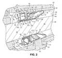
- FIG. 2is a cutaway perspective view of one embodiment
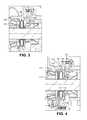
- FIG. 3is a cut away side view of another embodiment
- FIG. 4is a cut away side view of another embodiment
- FIG. 5is a cut away side view of another embodiment
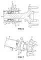
- FIG. 6is a cut away side view of another embodiment
- FIG. 7is a perspective view of the embodiment of FIG. 6 ;
- FIG. 8is another embodiment
- FIG. 9is a cut away side view of another embodiment.
- the differential 12comprises a differential housing 14 and a plurality of gears within the housing 14 .
- the gearsare typically at least one side gear 16 and at least one pinion gear 18 .
- the differential housing 14is connected to a ring gear 20 , which is in driving contact with a drive pinion gear 22 .
- the drive pinion gear 22is connected to a source for rotation, such as a drive shaft 24 or the like.
- Two shaftsare typically connected to the differential 12 . More particularly, a first end portion of one shaft 26 is connected to one of the differential side gears. A second, opposite end portion of the shaft 26 is connected to a wheel (not shown). A second shaft 28 is connected to the differential and another wheel in a similar fashion.
- the shaftsare typically round in cross section.
- the differential 12allows the wheels located at the ends of the shafts 26 , 28 to rotate at different speeds, such as when the vehicle is going around a corner, even though the shafts 26 , 28 are connected to the same rotational power source.
- the shaft 30is located in a shaft housing 32 .
- the shaft housing 32typically extends from the differential housing to the second end portion of the shaft 32 , which may be adjacent the wheel.
- the shaft housing 32is substantially tubular with a hollow interior 34 to accommodate the shaft 30 .
- the shaft housing 32has an outer surface 36 and an inner surface 38 where the inner surface 38 defines the hollow interior 34 .
- An outer surface 40 of the shaft 30is spaced apart from the inner surface 38 of the shaft housing 32 by a gap.
- the second leg 48extends away from the first leg 46 toward the outer surface 40 of the shaft 30 .
- the second leg 48extends at an angle toward the outer surface 40 of the shaft 30 .
- the angle of the second leg 48may be such that it extends at least partially radially under the first leg 46 .
- the second leg 48may also comprise an end portion 50 that extends parallel to the outer surface 40 of the shaft 30 .
- the second leg end portion 50contacts and extends parallel along the outer surface 40 of the shaft 30 .
- the second leg end portion 50may be of equal length compared to the first leg 46 or it may be longer or shorter. In the depicted embodiment, the second leg end portion 50 is shorter than the first leg 46 .
- connection portion 52may be curvilinear, but the present embodiment is not limited to a curvilinear connection portion 52 . Instead, the connection portion 52 maybe angled, such as obtuse or acute.
- the shaft guide 44may be unitary and one piece, as depicted in the figures, or it may be comprised of one or more pieces.
- the shaft guide 44in whole or in part, may be constructed of a single material or it may be comprises of a plurality of materials. Suitable materials include metal, plastic, paper, cardboard, and/or fiberglass.
- An aperture 54extends through a central portion 56 of the shaft guide 44 .
- the aperture 54is defined by the second leg end portion 50 .
- the second leg end portion 50defines the aperture 54 with a constant diameter. The diameter is slightly larger than the diameter of the shaft 30 .
- the shaft guide 44assists in locating the shaft 30 as it is inserted into the shaft housing 32 .
- the shaft guide 44locates the shaft 30 in a predetermined preferred position with the shaft housing 32 . More particularly, the shaft guide 44 ensures that when the shaft 30 is installed in the housing 32 , that it does not damage an anti-lock brake rotor cartridge, described in more detail below.
- the second leg 48 of the shaft guide 44and to a certain extent, the first leg 46 of the shaft guide 44 , direct an end portion 58 of the shaft 30 to a center of the shaft housing 32 when the shaft 30 is installed.
- the end portion 58 of the shaft 30may contact either leg 46 , 48 during the installation process.
- the shape of the legs 46 , 48and in particular the angled inwardly directed second leg 48 , guides the shaft end portion 58 to the center of the housing 32 .
- the shaft end portion 58extends through the aperture 54 in the shaft guide 44 .
- the shaft end portion 58extends beyond the aperture 54 and is connected to the differential 12 .
- a body portion 60 of the shaft 30is located through the aperture 54 . More particularly, the outer surface 40 of the shaft body portion 60 is located adjacent, and may be in contact with, the second leg end portion 50 .
- the shaft guide 44is helpful because often the shaft 30 is installed into the shaft housing 32 blindly. In other words, the installer cannot see the end portion 58 of the shaft 30 as it moves into the shaft housing 32 . Therefore, the installer cannot know the exact axial position, radial position or angle of the shaft end portion 58 inside the shaft housing 32 . Installation of the shaft 30 without being able to see inside the housing 32 is complicated by the fact that the shaft 30 , its housing 32 and the various parts described herein are heavy metal parts that are not easy to manipulate, particularly manually.
- An anti-lock brake sensor assembly 62is located axially inward from the shaft guide 44 .
- the assembly 62comprises a sensor 64 , an inner piece 66 and an outer piece 68 .
- the sensor 64is removably located within a sensor mount 70 .
- the sensor mount 70may be located through the differential case 12 , or a shoulder extension thereof. In the depicted embodiment, the sensor mount 70 is located through the shoulder extension.
- the inner piece 66 and the outer piece 68comprise an anti-lock brake rotor tone ring cartridge 72 .
- the cartridge 72may be installed in whole at the same time or its individual parts may be installed in steps.
- An aperture 74extends through the sensor mount 70 from an outer surface 76 thereof through the shaft housing 32 .
- An anti-lock brake sensor 64 as known to those skilled in the artis located within the sensor mount aperture 74 .
- the sensor 64By sensing changes in a magnetic field, the sensor 64 senses tone ring teeth that rotate past it. The sensed information is provided to a computer to calculate wheel speed and to monitor braking. The tone ring will be described below.
- the aperture 74is located radially outward from the second leg end portion 48 . It can be appreciated, however, that the aperture 74 , and thus the sensor 64 , and the entire assembly 62 can be located other than as depicted.
- the outer piece 68may be such as a stamped metal, but other materials manufactured in other ways, such as casting, forging, molding and the like may be used.
- the outer piece 68may have a U-shaped cross section, as shown in the figures.
- the U-shapemay be a single piece or it may be comprised of more than one piece.
- the U-shapemay be comprised of an inboard radially inward extending leg 78 , an outboard radially inward extending leg 80 , where these legs are connected by an axially extending leg 82 .
- the axially extending leg 82may be oriented parallel to the outer surface 36 of the shaft 30 and the inner surface 38 of the shaft housing 32 .
- the axially extending leg 82may be directly attached to the inner surface 38 of the shaft housing 32 . The attachment may be made by fasteners, adhesives, male/female fittings and/or welding.
- the two radially inwardly extending legs 78 , 80may be oriented transverse to the axially extending leg 82 or the radially extending legs 78 , 80 may extend inwardly at an angle other than 90 degrees to the axially extending leg 82 .
- the anglesmay be the same or different from one another.
- the inner piece 66may also be such as stamped metal, but other materials manufactured in other ways, such as casting, forging, molding and the like may also be used.
- the inner piece 66may be a single piece, or it may be comprised of more than one piece.
- the inner piece 66is comprised of a first radially extending leg 84 , a second radially extending leg 86 , a first axially extending leg 88 , a second axially extending leg 90 and a third axially extending leg 92 . All the legs 84 , 86 , 88 , 90 , 92 are preferably connected together.
- the first radially extending leg 84is located axially nearest the differential 12 .
- the first radially extending leg 84is located parallel but axially spaced apart from the inboard radially inwardly extending leg 78 of the outer piece 68 .
- the first radially extending leg 84is located axially inboard with respect to the inboard radially inwardly extending leg 78 of the outer piece 68 .
- the first radially extending leg 84may have a plurality of apertures 94 extending through it.
- the apertures 94are preferably circumferentially spaced about the leg 84 at equal intervals from one another.
- the apertures 94 in FIG. 2have the same general shape as one another. It is permissible, however, for the apertures 94 to have different spacing and shapes from those depicted in the figure.
- the first radially extending leg 84does not extend radially to the inner surface 38 of the shaft housing 32 .
- a radial gap 96exists between the end of the first radially extending leg 84 and the inner surface 38 of the shaft housing 32 .
- An axial gap 98exists between the end of the first radially extending leg 84 and an end 100 of the shaft housing 32 so that the end of the leg 84 is located axially inboard from the housing end 100 .
- the first radially extending leg 84transitions into the first axially extending leg 88 .
- the two legs 84 , 88are unitary and integrally formed with one another.
- the first axially extending leg 88may be oriented transverse to the first radially extending leg 84 , but other angles are permissible.
- the first axially extending leg 88may be parallel to the outer surface 40 of the shaft 30 and the inner surface 38 of the shaft housing 32 .
- the second axially extending leg 90is located radially inward from the first axially extending leg 88 .
- the second axially extending leg 90is parallel both the first axially extending leg 88 and the outer surface 40 of the shaft 30 .
- a bell 102is connected to the second axially extending leg 90 .
- the bell 102is connected to a radially inner surface 104 of the second axially extending leg 90 .
- the bell 102is located in direct contact with the outer surface 40 of the shaft 30 .
- the bell 102is rotationally fixed to the outer surface 40 of the shaft 30 .
- the bell 102may be rotationally fixed through the use of one or more convolutions 106 , or beads, integrally formed with the bell 102 and in contact with the shaft 30 .
- the bell 102extends axially along the second leg 90 and extends past the second leg 90 in both the inboard and outboard directions.
- An inboard end portion 108 of the bell 102wraps around an inboard end portion 110 of the second leg 90 to axially secure the bell 102 and second leg 90 .
- an inner surface 114 of the bell 102diverges from the outer surface 40 of the shaft 30 .
- the bell 102diverges at a predetermined length and angle so as to create a funnel-shape.
- a curvilinear surface 116connects the funnel shape to a cylindrical surface 118 that extends to the second radially extending leg 86 .
- the cylindrical surface 118 and the second radially extending leg 86are in direct contact with another.
- the bell 102forms another shaft guide that directs the shaft 30 during the assembly process into the proper location in a manner similar to the shaft guide 44 described above. More particularly, the inner diverging surface 114 , or funnel shape, of the bell 102 functions to guide the end portion 58 of the shaft 30 into the center of the shaft housing 32 , where it can then be connected to the differential.
- the second radially extending leg 86extends radially outward from, and transverse to, the first and second axially extending legs 88 , 90 .
- the second radially extending leg 86may also extend at other angles to the first axially extending leg 88 .
- the second radially extending leg 86is parallel to, but axially offset from, the first radially extending leg 84 .
- the second radially extending leg 86is located axially outboard from the first radially extending leg 84 .
- the second radially extending leg 86has a plurality of apertures 120 extending therethrough.
- the apertures 120are preferably circumferentially spaced about the leg 86 at equal intervals from one another.
- the apertures 120 in FIG. 2have the same general shape as one another. It is permissible, however, for the apertures 120 to have different spacing and shapes from those depicted in the figure.
- the apertures 120may be aligned or misaligned with the first radially extending leg apertures 94 . Preferably, they are aligned with one another and equal in number.
- the second radially extending leg 86extends radially outward substantially equivalent to the first radially extending leg 84 .
- An end of the second radially extending leg 86is located adjacent the inner surface 38 of the shaft housing 32 , but separated by a gap 122 .
- An axial gap 124separates the second radially extending leg 86 and the outboard radially inward extending leg 80 from the first piece 66 .
- the second radially extending leg 86transitions into the third axially extending leg 92 .
- the third axially extending leg 92is substantially transverse to the second radially extending leg 86 .
- the legs 86 , 92are unitary and integrally formed with one another.
- the third axially extending leg 92extends parallel to the outer surface 40 of the shaft 30 and the inner surface 38 of the shaft housing 32 .
- the third axially extending leg 92is separated from the inner surface 38 of the shaft housing 32 by a constant radial gap 126 .
- the third axially extending leg 92extends above the bell 102 and axially to the end portion 50 of the second leg 48 of the shaft guide 44 .
- the third axially extending leg 92extends axially to the sensor aperture 74 .
- the third axially extending leg 92extends in the axial direction so that the leg 92 terminates axially beneath the aperture 74 .
- An outer surface 128 of the third axially extending leg 92has a plurality of teeth 130 extending from the outer surface 128 and/or formed with the outer surface 128 .
- the teeth 130extend continuously circumferentially about the outer surface 128 of the third leg 92 .
- the teeth 130are equally spaced from one another.
- the teeth 130comprise the tone ring for the ABS sensor system.
- the teeth 130may also be separately attached to the axially extending leg 92 .
- the position of the third axially extending leg 92is predetermined so that the teeth 130 are positioned at a predetermined axially and radially fixed position with respect to the sensor 64 .
- the fixed position of the teeth 130results in the sensor 64 obtaining an accurate speed and direction of the teeth 130 .
- the second radially extending leg 86 of the inner piece 66cannot move axially beyond the outboard radially inward extending leg 80 of the outer piece 68 .
- the inboard radially inward extending leg 78 of the outer piece 68prevents axial movement of the first radially extending leg 84 of the outer piece 68 .
- the two complimentary pieces 66 , 68maintain the teeth 130 adjacent the sensor 64 so that the sensor 64 can reliably read the teeth 130 at all times.
- lubricant located between the shaft 30 and shaft housing 32is permitted to flow through the apertures 94 , 120 in the legs 84 , 86 and around the ends of the legs 84 , 86 .
- a possible lubricant flow path 132 through the legs 78 , 80 , 84 , 86 and around the legs 78 , 80 , 82 , 84 , 86 , 88 , 90 , 92is depicted in FIG. 2 .
- FIG. 3depicts an alternative embodiment wherein the outer piece 68 is installed within a differential carrier 134 .
- the outer piece 68is as described above, but the outer piece axially extending leg 82 is parallel to and attached to an inner surface 136 of the differential carrier 134 .
- a sensor aperture 138is located through the differential carrier 134 so as to permit location of the sensor 64 adjacent the tone ring teeth 130 on the third axially extending leg 92 .
- the inner piece 66is located adjacent the shaft 30 , but inboard from its location described above so at to also be within the differential carrier 134 .
- the inner and outer pieces 66 , 68may be located outboard of a differential bearing 140 and inboard of the shaft end portion 58 , as shown in the figure.
- FIG. 5depicts yet another embodiment.
- the outer piece 68is located within the shaft housing 32 . More particularly, the axially extending leg 82 of the outer piece 68 is in direct contact with the inner surface 38 of the shaft housing 32 .
- the first axially extending leg 88 of the inner piece 66 ′is connected to an inboard radially extending leg 142 .
- An inboard axially extending leg 144is directly connected to the inboard radially extending leg 142 .
- the inboard axially extending leg 144extends in an axially inboard fashion from the inner piece 66 ′.
- An outer surface 146 of the inboard axially extending leg 144has a ring comprising a plurality of teeth 148 extending therefrom and/or formed therewith.
- the teeth 148preferably extend continuously circumferentially about the outer surface 146 of the leg 144 to form a tone ring as described above.
- the inner piece 66 ′has a second axially extending leg 90 , as described above, and a second radially extending leg 86 .
- the second radially extending leg 86in this embodiment defines a cup to hold the bell 102 ′.
- the second radially extending leg 86does not have the tone ring.
- the inner and outer pieces 66 ′, 68can be substantially located within the shaft housing 32 , except for the tone ring.
- FIG. 4depicts yet another embodiment wherein the outer piece 68 is installed within a threaded bearing adjuster 150 .
- the threaded bearing adjuster 150has an inner surface 152 and an outer surface 154 .
- the outer surface 154has a set of threads 156 .
- the threads 156engage a complimentary set of threads 158 on an inner surface 160 of a differential carrier 170 .
- the engaged threads 156 , 158permit the adjuster 150 to provide axial preload to an adjacent differential bearing 172 .
- the adjuster 150is in direct contact with the outer race 174 of the differential bearing 172 .
- the axially extending leg 82 of the outer piece 68is in direct contact with the inner surface 160 of the bearing adjuster 150 . More particularly, the inner surface 160 of the adjuster 150 has an L-shape.
- the axially extending leg 82is in direct contact with an axially extending leg 176 of the L, while the outboard radially extending leg 80 of the inner piece 66 is in direct contact with the radially extending leg 178 of the L.
- the inner piece 66is located adjacent the shaft 30 .
- the inner and outer pieces 66 , 68may be located outboard of a differential bearing 180 and inboard of the shaft housing end 100 , as shown in the figure.
- FIG. 6depicts the structures described and depicted in FIG. 2 , but in a different location and without the shaft guide 44 .
- the inner and outer pieces 66 , 68are located adjacent a wheel end 181 .
- the axially extending leg 82 of the outer piece 68is pressed fit into the shaft housing 32 .
- the shaft 30is rotatably mounted within the housing 32 by a wheel end bearing 182 .
- the shaft 30passes through the interior of the wheel end bearing 182 and the inner piece 66 .
- the sensor 64is located adjacent the teeth 130 to pick up the magnetic field and deliver the sensed field to a vehicle system ECU (not pictured).
- the sensor 64is located onto the shaft housing 32 through an ABS boss 184 to position the sensor 64 a correct distance away from the teeth 130 .
- FIG. 7shows the ABS boss 184 integrated into the tube flange 186 .
- the integrated tube flange 186 and boss 184are welded together to the housing 32 . After welding, a hole is drilled into the boss 184 and into the housing 32 to house the sensor 64 .
- FIG. 8depicts an alternative embodiment wherein the tube flange 186 and the boss 184 are not integrated with one another. Instead, the tube flange 186 and the boss 184 are separately formed and separately attached, such as by welding, to the housing 32 .
- This embodimentpermits the sensor 64 to be placed in a location other than at the tube flange 186 . This may be particularly advantageous to keep the sensor from heat generated by braking at the wheel end.
- FIG. 9depicts yet another embodiment.
- the differential 188comprises a differential housing 190 and a plurality of gears within the housing 190 .
- the gearsare typically at least one side gear 192 and at least one pinion gear 194 .
- the differential housing 190is located in a differential carrier 196 , which is partially depicted in the figure.
- a first end 198 of a shaft 200is connected to one of the side gears 192 .
- the shaft 200has a substantially constant outer diameter, except adjacent a bearing adjuster 202 and an antilock brake sensor assembly 204 . Radially inward from the bearing adjuster 202 and the assembly 204 , the outer diameter of the shaft 200 increases. The increased diameter portion 206 of the shaft 200 in this location functions as a lubricant dam. The dam prevents or reduces lubricant from going between the assembly 204 and the shaft 200 , which could cause the assembly 204 not to rotate with the shaft 200 and thus provide an erroneous signal.
- the shaft 200is located in a shaft housing 208 .
- the shaft housing 208typically extends from the differential carrier 196 and substantially the length of the shaft 200 . In the depicted embodiment, the shaft housing 208 fits within the differential carrier 196 .
- the shaft housing 208is substantially tubular with a hollow interior 210 to accommodate the shaft 200 .
- the shaft housing 208has an outer surface 212 and an inner surface 214 where the inner surface 214 defines the hollow interior 210 .
- An outer surface 216 of the shaft 200is spaced apart from the inner surface 214 of the shaft housing 208 by a gap 218 .
- the differential housing 190is mounted for rotation within the differential carrier 196 .
- a differential bearing 220is located between the housing 190 and the carrier 196 .
- the bearing adjuster 202is threadably attached at its outside surface 222 to an inside surface 224 of the carrier 196 .
- the axial position of the bearing adjuster 202can be changed by threading the adjuster 202 into or away from the bearing 220 .
- the movement of the bearing adjuster 202 with respect to the differential bearing 220changes the backlash and preload on the bearing 220 .
- the position of the bearing adjuster 202is locked by an insert 226 .
- One end of the insert 226is located in one of the plurality of holes 228 in the bearing adjuster 202 .
- the other end of the insert 226is secured by a mechanical fastener 230 or the like.
- An inner surface 232 of the bearing adjuster 202houses the anti-lock brake sensor assembly 204 .
- the assembly 204comprises a sensor 234 , an inner piece 236 and an outer piece 238 .
- the inner piece 236comprises an L-shaped stamping.
- a first leg 240 of the Lextends parallel the outer surface 216 of the shaft 200 .
- the second leg 242 of the Lextends transverse the first leg 240 on an end thereof.
- the second leg 242extends radially outward from the outer surface 216 of the shaft 200 .
- the first and second legs 240 , 242are preferably one-piece, integrally formed and unitary with one another.
- the first leg 240 and at least a portion of the second leg 242are located in an elastomeric material 244 .
- the elastomeric material 244may be bonded to the legs 240 , 242 .
- the elastomeric material 244also functions to bond the first leg 240 to the outer surface 216 of the shaft 200 .
- the elastomeric material 244may form an angled surface 246 on the inboard side of the second leg 242 .
- a tone ring 248is connected to the inner piece 236 . More particularly, the tone ring 248 has an inner surface 250 that connects with the first leg 240 opposite the second leg 242 . The tone ring 248 may be pressed on the first leg 240 . The tone ring 248 has at least two spokes 252 that extend radially outward from the first leg 240 . The spokes 252 support tone ring teeth 254 . The teeth 254 are positioned adjacent the tone ring sensor 234 extending through a shoulder 258 of the differential carrier 196 .
- the outer piece 238comprises an L-shaped stamping.
- a first leg 260extends parallel to and is directly connected with the inner surface 232 of the bearing adjuster 202 .
- a second leg 262is connected to an end of the first leg 260 .
- the second leg 262extends radially inward toward the shaft 200 .
- the second leg 262comprises three portions.
- a first portion 264extends transverse the first leg 260
- a second portion 266is angled with respect to the first portion 264
- a third portion 268is parallel the first portion but axially offset therefrom.
- the second leg third portion 268 of the outer piece 238is axially offset from the second leg inner piece 242 .
- the first and second legs 260 , 262are preferably one piece, integrally formed and unitary with one another.
- An elastomeric material 270is located about the third portion 268 of the outer piece 238 .
- the elastomeric material 270abuts the second leg 242 of the inner piece 234 .
- the elastomeric material 270may be ring shaped and have a square cross-section.
- the outer piece 238through the third portion 268 and its elastomeric material 270 , prevents the inner piece 236 , and the tone ring 248 mounted thereon, from moving axially away from the sensor 234 . Additionally, the tone ring 248 prevents the outer piece 238 , from moving axially away from the sensor 234 . More particularly, the elastomeric material 270 abuts the tone ring 248 and prevents it, and the outer piece 238 , from moving in the outboard axial direction. The arrangement thus ensures accurate tone ring measurements by the sensor 234 .
Landscapes
- Engineering & Computer Science (AREA)
- General Engineering & Computer Science (AREA)
- Mechanical Engineering (AREA)
- Physics & Mathematics (AREA)
- General Physics & Mathematics (AREA)
- Transportation (AREA)
- Retarders (AREA)
- Braking Arrangements (AREA)
- Regulating Braking Force (AREA)
- Braking Elements And Transmission Devices (AREA)
Abstract
Description
Claims (20)
Priority Applications (6)
| Application Number | Priority Date | Filing Date | Title |
|---|---|---|---|
| US13/920,111US9207102B2 (en) | 2012-06-21 | 2013-06-18 | Anti-lock brake rotor tone ring cartridge and shaft guide |
| ARP130102197AAR093219A1 (en) | 2012-06-21 | 2013-06-19 | TOOTHED ROLL CARTRIDGE OF ANTI-LOCK BRAKE ROTOR AND VASTAGO GUIDE |
| EP13734242.4AEP2864166B1 (en) | 2012-06-21 | 2013-06-19 | Anti-lock brake rotor tone ring cartridge and shaft guide |
| JP2015518535AJP6168714B2 (en) | 2012-06-21 | 2013-06-19 | Tone ring cartridge |
| PCT/US2013/046462WO2013192262A1 (en) | 2012-06-21 | 2013-06-19 | Anti-lock brake rotor tone ring cartridge and shaft guide |
| EP15178197.8AEP2965959B1 (en) | 2012-06-21 | 2013-06-19 | Anti-lock brake rotor tone ring cartridge |
Applications Claiming Priority (2)
| Application Number | Priority Date | Filing Date | Title |
|---|---|---|---|
| US201261662720P | 2012-06-21 | 2012-06-21 | |
| US13/920,111US9207102B2 (en) | 2012-06-21 | 2013-06-18 | Anti-lock brake rotor tone ring cartridge and shaft guide |
Publications (2)
| Publication Number | Publication Date |
|---|---|
| US20130340544A1 US20130340544A1 (en) | 2013-12-26 |
| US9207102B2true US9207102B2 (en) | 2015-12-08 |
Family
ID=48746660
Family Applications (1)
| Application Number | Title | Priority Date | Filing Date |
|---|---|---|---|
| US13/920,111Active2034-07-25US9207102B2 (en) | 2012-06-21 | 2013-06-18 | Anti-lock brake rotor tone ring cartridge and shaft guide |
Country Status (5)
| Country | Link |
|---|---|
| US (1) | US9207102B2 (en) |
| EP (2) | EP2864166B1 (en) |
| JP (1) | JP6168714B2 (en) |
| AR (1) | AR093219A1 (en) |
| WO (1) | WO2013192262A1 (en) |
Cited By (2)
| Publication number | Priority date | Publication date | Assignee | Title |
|---|---|---|---|---|
| US11498362B2 (en) | 2019-12-13 | 2022-11-15 | Dana Heavy Vehicle Systems Group, Llc | Tone wheel assembly, an axle assembly made therewith, and a method of manufacturing an axle assembly |
| US11614455B2 (en) | 2020-12-09 | 2023-03-28 | Dana Heavy Vehicle Systems Group, Llc | System for shielding a tone ring in a vehicle axle |
Families Citing this family (2)
| Publication number | Priority date | Publication date | Assignee | Title |
|---|---|---|---|---|
| GB2524819B (en)* | 2014-04-04 | 2018-05-23 | Jaguar Land Rover Ltd | Speed sensor of a vehicle transmission |
| US11125317B2 (en) | 2019-05-07 | 2021-09-21 | Dana Heavy Vehicle Systems Group, Llc | Guide member and a drive unit assembly using the same |
Citations (48)
| Publication number | Priority date | Publication date | Assignee | Title |
|---|---|---|---|---|
| US3551712A (en)* | 1968-07-25 | 1970-12-29 | Kelsey Hayes Co | Sensor with flexible coupling |
| US3916234A (en)* | 1973-05-24 | 1975-10-28 | Wagner Electric Corp | Vehicle wheel speed sensor |
| US3949841A (en) | 1975-05-07 | 1976-04-13 | Rockwell International Corporation | Wheel speed sensor for drive axle |
| US3988624A (en)* | 1971-03-15 | 1976-10-26 | Eaton Corporation | Self-gauging sensor assembly |
| US4029180A (en)* | 1974-04-12 | 1977-06-14 | Eaton Corporation | Tubular wheel speed sensor for an anti-skid system |
| US4090592A (en) | 1975-12-15 | 1978-05-23 | Rockwell International Corporation | Wheel speed sensor for drive axle |
| USRE30847E (en)* | 1974-04-12 | 1982-01-12 | Eaton Corporation | Tubular wheel speed sensor |
| US4689557A (en) | 1985-02-06 | 1987-08-25 | Lucas Industries Public Limited Company | In-axle vehicle wheel speed sensing device |
| US4901562A (en) | 1989-03-31 | 1990-02-20 | Dana Corporation | Vehicle wheel speed sensor for a drive axle |
| US4953670A (en) | 1988-11-30 | 1990-09-04 | Dana Corporation | Vehicle wheel speed sensor |
| EP0443939A1 (en) | 1990-02-21 | 1991-08-28 | Snr Roulements | Sensor to determine rotational parameters |
| US5067350A (en) | 1990-02-21 | 1991-11-26 | The Torrington Company | Sensor to determine rotational parameters |
| US5223760A (en) | 1988-08-24 | 1993-06-29 | Rockwell International Corporation | Wheel speed sensor for drive axle |
| US5227719A (en) | 1990-09-07 | 1993-07-13 | Eaton Corporation | Drive axle in-axle annular speed sensor |
| US5476272A (en) | 1994-01-19 | 1995-12-19 | Federal-Mogul Corporation | Speed sensor ring for vehicle anti-lock brake system |
| US5486757A (en) | 1993-08-24 | 1996-01-23 | Dana Corporation | Wheel-speed sensors for motor vehicle mounted in the spreader holes of a differential carrier housing |
| US5564839A (en) | 1992-10-29 | 1996-10-15 | Nsk Ltd. | Bearing unit for wheel with speed sensor |
| US5570013A (en) | 1993-03-15 | 1996-10-29 | The Torrington Company | Speed sensor assembly having a fluid seal carrier and piloting cup |
| US5584777A (en) | 1994-05-18 | 1996-12-17 | Dr. Ing. H.C.F. Porsche Ag | Differential cage for absorbing shock mounted in a differential casing |
| US5603575A (en) | 1994-10-20 | 1997-02-18 | Nsk Ltd. | Rolling bearing unit with rotating speed detector |
| US5695289A (en) | 1995-07-10 | 1997-12-09 | Nsk, Ltd. | Rolling bearing unit having tone wheel |
| US5757084A (en) | 1995-09-15 | 1998-05-26 | Consolidated Metco, Inc. | Wheel hub assembly and method of installing a hub on an axle |
| US5947611A (en) | 1996-01-22 | 1999-09-07 | Nsk Ltd. | Rolling bearing unit with tone wheel |
| US6149244A (en) | 1998-05-29 | 2000-11-21 | Consolidated Metco Inc. | Wheel hub assembly and method of installing a hub on an axle |
| US6238015B1 (en)* | 1998-12-31 | 2001-05-29 | Francisco J. Garcia | Anti-lock brake sensor holder |
| US20020175258A1 (en)* | 2001-05-23 | 2002-11-28 | White Jay D. | Bracket for anti-lock braking system sensor |
| US20030050749A1 (en)* | 2001-09-12 | 2003-03-13 | Cervantez Jesse W. | Direction/distance sensing vehicle function control system |
| US6549001B1 (en) | 2001-11-02 | 2003-04-15 | Skf Usa Inc. | Unitized tone ring assembly |
| US20030160605A1 (en) | 2002-02-26 | 2003-08-28 | Michalek John Stanley | Press-in exciter ring assembly |
| US6664780B2 (en) | 2001-11-02 | 2003-12-16 | Skf Usa Inc. | Unitized tone ring assembly |
| DE10237504A1 (en)* | 2002-08-16 | 2004-03-11 | Knorr-Bremse Systeme für Nutzfahrzeuge GmbH | Pole ring impulse generation device for attachment to a motor vehicle wheel has an improved attachment mechanism comprising a projection that extends into a matching groove in the wheel hub, brake disk or similar |
| US6929332B2 (en) | 2002-11-27 | 2005-08-16 | Arvinmeritor Technology, Llc | Stamped ABS sensor bracket |
| US6957918B2 (en) | 2003-10-27 | 2005-10-25 | American Axle & Manufacturing, Inc. | Axle shaft assembly |
| US20060124411A1 (en)* | 2004-12-10 | 2006-06-15 | The Boler Company | Corrosion-resistant ABS tone ring |
| US20060272906A1 (en)* | 2005-06-03 | 2006-12-07 | Arvinmeritor Technology, Llc | Brake rotor and tone ring assembly |
| US7194921B1 (en) | 2005-04-22 | 2007-03-27 | Torque-Traction Technologies, Llc | Speed-sensing device and method for assembling the same |
| US7205760B2 (en) | 2004-03-22 | 2007-04-17 | American Axle & Manufacturing, Inc. | Beam axle with integral sensor mount and target |
| US7241243B2 (en)* | 2003-10-06 | 2007-07-10 | American Axle & Manufacturing, Inc. | Electronic locking differential with bulkhead connector |
| US7288930B2 (en) | 2002-12-23 | 2007-10-30 | Siemens Vdo Automotive Corporation | Wheel-speed sensor |
| US7384359B2 (en) | 2005-05-26 | 2008-06-10 | American Axle & Manufacturing, Inc. | Method and apparatus for transmitting axle sensor data |
| US7503213B2 (en) | 2006-04-27 | 2009-03-17 | American Axle & Manufacturing, Inc. | Bimetallic sensor mount for axles |
| US20090188762A1 (en)* | 2008-01-30 | 2009-07-30 | Hester Larry B | Disc Brake Assembly With Tone Ring |
| US20090218183A1 (en)* | 2005-09-30 | 2009-09-03 | Performance Friction Corporation | Brake rotor and abs tone ring attachment assembly that promotes in plane uniform torque transfer distribution |
| US20100032251A1 (en)* | 2008-08-08 | 2010-02-11 | International Truck Intellectual Property Company, Llc | Tone Ring for an Anti-Lock Brake System |
| US20100272380A1 (en)* | 2009-04-24 | 2010-10-28 | Zink Frederick E | Drive axle assembly with wheel speed measurement system |
| US20100281975A1 (en) | 2009-05-07 | 2010-11-11 | Lemerise John Edward | Rotational Speed Sensor Assembly |
| US20110009199A1 (en) | 2008-04-04 | 2011-01-13 | Kiyoshige Yamauchi | Wheel bearing apparatus and axle module |
| US20110133046A1 (en) | 2009-12-03 | 2011-06-09 | Ford Global Technologies, Llc | Wheel sensor mounting device |
Family Cites Families (1)
| Publication number | Priority date | Publication date | Assignee | Title |
|---|---|---|---|---|
| JPH08133036A (en)* | 1994-11-14 | 1996-05-28 | Toyota Motor Corp | Wheel speed detector |
- 2013
- 2013-06-18USUS13/920,111patent/US9207102B2/enactiveActive
- 2013-06-19WOPCT/US2013/046462patent/WO2013192262A1/enactiveApplication Filing
- 2013-06-19ARARP130102197Apatent/AR093219A1/enactiveIP Right Grant
- 2013-06-19JPJP2015518535Apatent/JP6168714B2/ennot_activeExpired - Fee Related
- 2013-06-19EPEP13734242.4Apatent/EP2864166B1/enactiveActive
- 2013-06-19EPEP15178197.8Apatent/EP2965959B1/enactiveActive
Patent Citations (56)
| Publication number | Priority date | Publication date | Assignee | Title |
|---|---|---|---|---|
| US3551712A (en)* | 1968-07-25 | 1970-12-29 | Kelsey Hayes Co | Sensor with flexible coupling |
| US3988624A (en)* | 1971-03-15 | 1976-10-26 | Eaton Corporation | Self-gauging sensor assembly |
| US3916234A (en)* | 1973-05-24 | 1975-10-28 | Wagner Electric Corp | Vehicle wheel speed sensor |
| US4029180A (en)* | 1974-04-12 | 1977-06-14 | Eaton Corporation | Tubular wheel speed sensor for an anti-skid system |
| USRE30847E (en)* | 1974-04-12 | 1982-01-12 | Eaton Corporation | Tubular wheel speed sensor |
| US3949841A (en) | 1975-05-07 | 1976-04-13 | Rockwell International Corporation | Wheel speed sensor for drive axle |
| US4090592A (en) | 1975-12-15 | 1978-05-23 | Rockwell International Corporation | Wheel speed sensor for drive axle |
| US4689557A (en) | 1985-02-06 | 1987-08-25 | Lucas Industries Public Limited Company | In-axle vehicle wheel speed sensing device |
| US5223760A (en) | 1988-08-24 | 1993-06-29 | Rockwell International Corporation | Wheel speed sensor for drive axle |
| US4953670A (en) | 1988-11-30 | 1990-09-04 | Dana Corporation | Vehicle wheel speed sensor |
| US4901562A (en) | 1989-03-31 | 1990-02-20 | Dana Corporation | Vehicle wheel speed sensor for a drive axle |
| EP0443939A1 (en) | 1990-02-21 | 1991-08-28 | Snr Roulements | Sensor to determine rotational parameters |
| US5067350A (en) | 1990-02-21 | 1991-11-26 | The Torrington Company | Sensor to determine rotational parameters |
| US5227719A (en) | 1990-09-07 | 1993-07-13 | Eaton Corporation | Drive axle in-axle annular speed sensor |
| US5564839A (en) | 1992-10-29 | 1996-10-15 | Nsk Ltd. | Bearing unit for wheel with speed sensor |
| US5570013A (en) | 1993-03-15 | 1996-10-29 | The Torrington Company | Speed sensor assembly having a fluid seal carrier and piloting cup |
| US5486757A (en) | 1993-08-24 | 1996-01-23 | Dana Corporation | Wheel-speed sensors for motor vehicle mounted in the spreader holes of a differential carrier housing |
| US5476272A (en) | 1994-01-19 | 1995-12-19 | Federal-Mogul Corporation | Speed sensor ring for vehicle anti-lock brake system |
| US5584777A (en) | 1994-05-18 | 1996-12-17 | Dr. Ing. H.C.F. Porsche Ag | Differential cage for absorbing shock mounted in a differential casing |
| US5603575A (en) | 1994-10-20 | 1997-02-18 | Nsk Ltd. | Rolling bearing unit with rotating speed detector |
| US5695289A (en) | 1995-07-10 | 1997-12-09 | Nsk, Ltd. | Rolling bearing unit having tone wheel |
| US5757084A (en) | 1995-09-15 | 1998-05-26 | Consolidated Metco, Inc. | Wheel hub assembly and method of installing a hub on an axle |
| US5947611A (en) | 1996-01-22 | 1999-09-07 | Nsk Ltd. | Rolling bearing unit with tone wheel |
| US6168315B1 (en) | 1996-01-22 | 2001-01-02 | Nsk Ltd. | Rolling bearing unit with tone wheel |
| US6149244A (en) | 1998-05-29 | 2000-11-21 | Consolidated Metco Inc. | Wheel hub assembly and method of installing a hub on an axle |
| US6238015B1 (en)* | 1998-12-31 | 2001-05-29 | Francisco J. Garcia | Anti-lock brake sensor holder |
| US20020175258A1 (en)* | 2001-05-23 | 2002-11-28 | White Jay D. | Bracket for anti-lock braking system sensor |
| US7559521B2 (en) | 2001-05-23 | 2009-07-14 | Hendrickson Usa, L.L.C. | Bracket for anti-lock braking system sensor |
| US20030050749A1 (en)* | 2001-09-12 | 2003-03-13 | Cervantez Jesse W. | Direction/distance sensing vehicle function control system |
| US6549001B1 (en) | 2001-11-02 | 2003-04-15 | Skf Usa Inc. | Unitized tone ring assembly |
| US6664780B2 (en) | 2001-11-02 | 2003-12-16 | Skf Usa Inc. | Unitized tone ring assembly |
| US20030160605A1 (en) | 2002-02-26 | 2003-08-28 | Michalek John Stanley | Press-in exciter ring assembly |
| US7233138B2 (en) | 2002-02-26 | 2007-06-19 | American Axle & Manufacturing, Inc. | Press-in exciter ring assembly |
| DE10237504A1 (en)* | 2002-08-16 | 2004-03-11 | Knorr-Bremse Systeme für Nutzfahrzeuge GmbH | Pole ring impulse generation device for attachment to a motor vehicle wheel has an improved attachment mechanism comprising a projection that extends into a matching groove in the wheel hub, brake disk or similar |
| US6929332B2 (en) | 2002-11-27 | 2005-08-16 | Arvinmeritor Technology, Llc | Stamped ABS sensor bracket |
| US7288930B2 (en) | 2002-12-23 | 2007-10-30 | Siemens Vdo Automotive Corporation | Wheel-speed sensor |
| US7241243B2 (en)* | 2003-10-06 | 2007-07-10 | American Axle & Manufacturing, Inc. | Electronic locking differential with bulkhead connector |
| US6957918B2 (en) | 2003-10-27 | 2005-10-25 | American Axle & Manufacturing, Inc. | Axle shaft assembly |
| US7205760B2 (en) | 2004-03-22 | 2007-04-17 | American Axle & Manufacturing, Inc. | Beam axle with integral sensor mount and target |
| US7345469B2 (en) | 2004-03-22 | 2008-03-18 | American Axle & Manufacturing, Inc. | Axle assembly with sensor mount |
| US20060124411A1 (en)* | 2004-12-10 | 2006-06-15 | The Boler Company | Corrosion-resistant ABS tone ring |
| US7194921B1 (en) | 2005-04-22 | 2007-03-27 | Torque-Traction Technologies, Llc | Speed-sensing device and method for assembling the same |
| US7384359B2 (en) | 2005-05-26 | 2008-06-10 | American Axle & Manufacturing, Inc. | Method and apparatus for transmitting axle sensor data |
| US20060272906A1 (en)* | 2005-06-03 | 2006-12-07 | Arvinmeritor Technology, Llc | Brake rotor and tone ring assembly |
| US20090218183A1 (en)* | 2005-09-30 | 2009-09-03 | Performance Friction Corporation | Brake rotor and abs tone ring attachment assembly that promotes in plane uniform torque transfer distribution |
| US7503213B2 (en) | 2006-04-27 | 2009-03-17 | American Axle & Manufacturing, Inc. | Bimetallic sensor mount for axles |
| US7878059B2 (en) | 2006-04-27 | 2011-02-01 | American Axle & Manufacturing, Inc. | Axle assembly with sensor assembly |
| US20090188762A1 (en)* | 2008-01-30 | 2009-07-30 | Hester Larry B | Disc Brake Assembly With Tone Ring |
| US20110009199A1 (en) | 2008-04-04 | 2011-01-13 | Kiyoshige Yamauchi | Wheel bearing apparatus and axle module |
| US20100032251A1 (en)* | 2008-08-08 | 2010-02-11 | International Truck Intellectual Property Company, Llc | Tone Ring for an Anti-Lock Brake System |
| US8167762B2 (en) | 2009-04-24 | 2012-05-01 | American Axle & Manufacturing, Inc. | Drive axle assembly with wheel speed measurement system |
| US20100272380A1 (en)* | 2009-04-24 | 2010-10-28 | Zink Frederick E | Drive axle assembly with wheel speed measurement system |
| US20100281975A1 (en) | 2009-05-07 | 2010-11-11 | Lemerise John Edward | Rotational Speed Sensor Assembly |
| US8230739B2 (en) | 2009-05-07 | 2012-07-31 | Ford Global Technologies, Llc | Rotational speed sensor assembly |
| US20120291545A1 (en) | 2009-05-07 | 2012-11-22 | Ford Global Technologies, Llc | Rotational Speed Sensor Assembly |
| US20110133046A1 (en) | 2009-12-03 | 2011-06-09 | Ford Global Technologies, Llc | Wheel sensor mounting device |
Cited By (2)
| Publication number | Priority date | Publication date | Assignee | Title |
|---|---|---|---|---|
| US11498362B2 (en) | 2019-12-13 | 2022-11-15 | Dana Heavy Vehicle Systems Group, Llc | Tone wheel assembly, an axle assembly made therewith, and a method of manufacturing an axle assembly |
| US11614455B2 (en) | 2020-12-09 | 2023-03-28 | Dana Heavy Vehicle Systems Group, Llc | System for shielding a tone ring in a vehicle axle |
Also Published As
| Publication number | Publication date |
|---|---|
| EP2965959A3 (en) | 2016-04-20 |
| US20130340544A1 (en) | 2013-12-26 |
| EP2864166A1 (en) | 2015-04-29 |
| JP2015523270A (en) | 2015-08-13 |
| EP2965959B1 (en) | 2020-12-09 |
| EP2864166B1 (en) | 2021-08-04 |
| WO2013192262A1 (en) | 2013-12-27 |
| JP6168714B2 (en) | 2017-07-26 |
| WO2013192262A8 (en) | 2014-07-17 |
| AR093219A1 (en) | 2015-05-27 |
| EP2965959A2 (en) | 2016-01-13 |
Similar Documents
| Publication | Publication Date | Title |
|---|---|---|
| EP2243673B1 (en) | Drive axle assembly with wheel speed measurement system | |
| KR100208056B1 (en) | Sensor system and its mounting method | |
| US9207102B2 (en) | Anti-lock brake rotor tone ring cartridge and shaft guide | |
| JP2005140320A5 (en) | ||
| US11072202B2 (en) | Wheel hub assembly provided with an innovative sensor holder | |
| JP4691879B2 (en) | Drive wheel hub unit | |
| EP3267073B1 (en) | Axle assembly having a support bearing assembly | |
| US11498362B2 (en) | Tone wheel assembly, an axle assembly made therewith, and a method of manufacturing an axle assembly | |
| JP2015523270A5 (en) | ||
| JP4085736B2 (en) | Rolling bearing device | |
| JP2011207298A (en) | Inner ring of bearing device for wheel | |
| CN113454356B (en) | Locking structure of component | |
| US8167498B2 (en) | Bearing apparatus for axle and method of manufacturing the same | |
| JP4032890B2 (en) | Rolling bearing device for vehicle | |
| JP2012087901A (en) | Sealing device and rolling bearing device | |
| US20120280560A1 (en) | Dual wheel axle assembly | |
| JP4483852B2 (en) | Rotating support device for wheel and assembling method thereof | |
| JP2009156751A (en) | Wheel speed detector | |
| JP2001219710A (en) | Vehicle axle assembly and vehicle axle bearing assembly | |
| JP2005282767A (en) | Rolling bearing device | |
| JP2007178254A (en) | Wheel speed detection device | |
| JP5740964B2 (en) | Rotational speed detector and wheel bearing device provided with the same | |
| JP4969797B2 (en) | Wheel bearing device with rotation speed detector | |
| JP2009150428A (en) | Wheel bearing with sensor | |
| JP2011121584A (en) | Rolling bearing unit for wheel |
Legal Events
| Date | Code | Title | Description |
|---|---|---|---|
| AS | Assignment | Owner name:DANA AUTOMOTIVE SYSTEMS GROUP, LLC, OHIO Free format text:ASSIGNMENT OF ASSIGNORS INTEREST;ASSIGNORS:METZGER, SETH A.;HORVATH, MICHAEL JASON;REEL/FRAME:030629/0968 Effective date:20130617 Owner name:DANA AUTOMOTIVE SYSTEMS GROUP, LLC, OHIO Free format text:ASSIGNMENT OF ASSIGNORS INTEREST;ASSIGNORS:METZGER, SETH A.;HORVATH, MICHAEL JASON;REEL/FRAME:030629/0679 Effective date:20130617 | |
| STCF | Information on status: patent grant | Free format text:PATENTED CASE | |
| MAFP | Maintenance fee payment | Free format text:PAYMENT OF MAINTENANCE FEE, 4TH YEAR, LARGE ENTITY (ORIGINAL EVENT CODE: M1551); ENTITY STATUS OF PATENT OWNER: LARGE ENTITY Year of fee payment:4 | |
| AS | Assignment | Owner name:CITIBANK, N.A., NEW YORK Free format text:SECURITY AGREEMENT (BRIDGE);ASSIGNORS:DANA HEAVY VEHICLE SYSTEMS GROUP, LLC;DANA LIMITED;DANA AUTOMOTIVE SYSTEMS GROUP, LLC;AND OTHERS;REEL/FRAME:052459/0001 Effective date:20200416 Owner name:CITIBANK, N.A., NEW YORK Free format text:SECURITY AGREEMENT SUPPLEMENT;ASSIGNORS:DANA HEAVY VEHICLE SYSTEMS GROUP, LLC;DANA LIMITED;DANA AUTOMOTIVE SYSTEMS GROUP, LLC;AND OTHERS;REEL/FRAME:052459/0224 Effective date:20200416 | |
| AS | Assignment | Owner name:FAIRFIELD MANUFACTURING COMPANY, INC., OHIO Free format text:RELEASE BY SECURED PARTY;ASSIGNOR:CITIBANK, N.A.;REEL/FRAME:053309/0686 Effective date:20200619 Owner name:DANA HEAVY VEHICLE SYSTEMS GROUP, LLC, OHIO Free format text:RELEASE BY SECURED PARTY;ASSIGNOR:CITIBANK, N.A.;REEL/FRAME:053309/0686 Effective date:20200619 Owner name:DANA AUTOMOTIVE SYSTEMS GROUP, LLC, OHIO Free format text:RELEASE BY SECURED PARTY;ASSIGNOR:CITIBANK, N.A.;REEL/FRAME:053309/0686 Effective date:20200619 Owner name:DANA LIMITED, OHIO Free format text:RELEASE BY SECURED PARTY;ASSIGNOR:CITIBANK, N.A.;REEL/FRAME:053309/0686 Effective date:20200619 | |
| MAFP | Maintenance fee payment | Free format text:PAYMENT OF MAINTENANCE FEE, 8TH YEAR, LARGE ENTITY (ORIGINAL EVENT CODE: M1552); ENTITY STATUS OF PATENT OWNER: LARGE ENTITY Year of fee payment:8 |