US9203198B2 - Low profile faceplate having managed connectivity - Google Patents
Low profile faceplate having managed connectivityDownload PDFInfo
- Publication number
- US9203198B2 US9203198B2US14/033,970US201314033970AUS9203198B2US 9203198 B2US9203198 B2US 9203198B2US 201314033970 AUS201314033970 AUS 201314033970AUS 9203198 B2US9203198 B2US 9203198B2
- Authority
- US
- United States
- Prior art keywords
- faceplate
- circuit board
- assembly
- contacts
- printed circuit
- Prior art date
- Legal status (The legal status is an assumption and is not a legal conclusion. Google has not performed a legal analysis and makes no representation as to the accuracy of the status listed.)
- Expired - Fee Related, expires
Links
Images


Classifications
- H—ELECTRICITY
- H01—ELECTRIC ELEMENTS
- H01R—ELECTRICALLY-CONDUCTIVE CONNECTIONS; STRUCTURAL ASSOCIATIONS OF A PLURALITY OF MUTUALLY-INSULATED ELECTRICAL CONNECTING ELEMENTS; COUPLING DEVICES; CURRENT COLLECTORS
- H01R13/00—Details of coupling devices of the kinds covered by groups H01R12/70 or H01R24/00 - H01R33/00
- H01R13/66—Structural association with built-in electrical component
- H01R13/665—Structural association with built-in electrical component with built-in electronic circuit
- H01R13/6658—Structural association with built-in electrical component with built-in electronic circuit on printed circuit board
- H—ELECTRICITY
- H01—ELECTRIC ELEMENTS
- H01R—ELECTRICALLY-CONDUCTIVE CONNECTIONS; STRUCTURAL ASSOCIATIONS OF A PLURALITY OF MUTUALLY-INSULATED ELECTRICAL CONNECTING ELEMENTS; COUPLING DEVICES; CURRENT COLLECTORS
- H01R25/00—Coupling parts adapted for simultaneous co-operation with two or more identical counterparts, e.g. for distributing energy to two or more circuits
- H01R25/006—Coupling parts adapted for simultaneous co-operation with two or more identical counterparts, e.g. for distributing energy to two or more circuits the coupling part being secured to apparatus or structure, e.g. duplex wall receptacle
- H—ELECTRICITY
- H01—ELECTRIC ELEMENTS
- H01R—ELECTRICALLY-CONDUCTIVE CONNECTIONS; STRUCTURAL ASSOCIATIONS OF A PLURALITY OF MUTUALLY-INSULATED ELECTRICAL CONNECTING ELEMENTS; COUPLING DEVICES; CURRENT COLLECTORS
- H01R31/00—Coupling parts supported only by co-operation with counterpart
- H01R31/06—Intermediate parts for linking two coupling parts, e.g. adapter
- H—ELECTRICITY
- H01—ELECTRIC ELEMENTS
- H01R—ELECTRICALLY-CONDUCTIVE CONNECTIONS; STRUCTURAL ASSOCIATIONS OF A PLURALITY OF MUTUALLY-INSULATED ELECTRICAL CONNECTING ELEMENTS; COUPLING DEVICES; CURRENT COLLECTORS
- H01R43/00—Apparatus or processes specially adapted for manufacturing, assembling, maintaining, or repairing of line connectors or current collectors or for joining electric conductors
- H01R43/20—Apparatus or processes specially adapted for manufacturing, assembling, maintaining, or repairing of line connectors or current collectors or for joining electric conductors for assembling or disassembling contact members with insulating base, case or sleeve
- H01R43/205—Apparatus or processes specially adapted for manufacturing, assembling, maintaining, or repairing of line connectors or current collectors or for joining electric conductors for assembling or disassembling contact members with insulating base, case or sleeve with a panel or printed circuit board
- H—ELECTRICITY
- H04—ELECTRIC COMMUNICATION TECHNIQUE
- H04L—TRANSMISSION OF DIGITAL INFORMATION, e.g. TELEGRAPHIC COMMUNICATION
- H04L41/00—Arrangements for maintenance, administration or management of data switching networks, e.g. of packet switching networks
- H04L41/14—Network analysis or design
- H—ELECTRICITY
- H01—ELECTRIC ELEMENTS
- H01R—ELECTRICALLY-CONDUCTIVE CONNECTIONS; STRUCTURAL ASSOCIATIONS OF A PLURALITY OF MUTUALLY-INSULATED ELECTRICAL CONNECTING ELEMENTS; COUPLING DEVICES; CURRENT COLLECTORS
- H01R24/00—Two-part coupling devices, or either of their cooperating parts, characterised by their overall structure
- H01R24/60—Contacts spaced along planar side wall transverse to longitudinal axis of engagement
- H01R24/62—Sliding engagements with one side only, e.g. modular jack coupling devices
- H01R24/64—Sliding engagements with one side only, e.g. modular jack coupling devices for high frequency, e.g. RJ 45
- Y—GENERAL TAGGING OF NEW TECHNOLOGICAL DEVELOPMENTS; GENERAL TAGGING OF CROSS-SECTIONAL TECHNOLOGIES SPANNING OVER SEVERAL SECTIONS OF THE IPC; TECHNICAL SUBJECTS COVERED BY FORMER USPC CROSS-REFERENCE ART COLLECTIONS [XRACs] AND DIGESTS
- Y10—TECHNICAL SUBJECTS COVERED BY FORMER USPC
- Y10T—TECHNICAL SUBJECTS COVERED BY FORMER US CLASSIFICATION
- Y10T29/00—Metal working
- Y10T29/49—Method of mechanical manufacture
- Y10T29/49002—Electrical device making
- Y10T29/49117—Conductor or circuit manufacturing
- Y10T29/49124—On flat or curved insulated base, e.g., printed circuit, etc.
- Y10T29/49128—Assembling formed circuit to base
Definitions
- a common connector configurationincludes a faceplate or outlet that is mounted on a structure such as a wall.
- the faceplatedefines a plurality of openings in which connectors can be mounted.
- a typical connectorincludes a modular jack defining a port sized for receiving a conventional modular plug.
- Other conventional types of connectorsinclude SC connectors, LC connector, MPO/MTP connector, ST connectors, MT-RJ connector, BNC connectors, USB connector, HDMI connector, S-Video connector, TERA connector, RJ-45 connector, F connectors and RCA connectors, for example.
- a faceplate assemblyincludes a faceplate member; at least one jack module; and a printed circuit board assembly.
- the faceplate memberdefines at least one opening extending between the front and the rear.
- the jack moduleis mounted in the opening of the faceplate member.
- the jack moduledefines a port accessible from the front of the faceplate member.
- the jack moduleincludes primary contacts that are configured to attach to conductors that are accessible from the rear of the faceplate member.
- the printed circuit board assemblyis mounted to the rear of the faceplate member.
- the printed circuit board assemblyincludes a printed circuit board; a first set of secondary contacts that are electrically connected to the printed circuit board; and a network connector that is electrically connected to the secondary contacts of the first set via the printed circuit board.
- the secondary contacts of the first setextend into the jack module.
- the secondary contacts of the first setare isolated from the primary contacts of the jack module.
- a managed connectivity systemincludes a wall outlet faceplate assembly; a network analyzer; and a termination device.
- the wall outlet faceplate assemblyincludes flush-mounted jacks. Each jack includes primary contacts and secondary contacts isolated from the primary contacts.
- the faceplate assemblyalso includes a network connector that is electrically coupled to the secondary contacts of each jack.
- the network analyzeris electrically coupled to the network connector to receive signals from the secondary contacts of each jack.
- the termination deviceincludes a plurality of electrical terminations. The primary contacts of at least one of the jacks is electrically connected to one of the electrical terminations.
- a method of installing a managed connectivity systemincludes mounting at least one media reading interface with secondary contacts to a printed circuit board; mounting a network connector to the printed circuit board so that the network connector is electrically connected to the secondary contacts; mounting the printed circuit board to a rear of a faceplate member so that the secondary contacts extend into an opening defined in the faceplate member and the network connector extends rearwardly of the faceplate member; and mounting a jack module at the opening defined in the faceplate member so that the secondary contacts extend into an interior of the jack module and are accessible through a port defined by the jack module.
- the secondary contactsremain isolated from primary contacts of the jack module.
- inventive aspectscan relate to individual features and combinations of features. It is to be understood that both the foregoing general description and the following detailed description are exemplary and explanatory only and are not restrictive of the broad inventive concepts upon which the embodiments disclosed herein are based.
- FIG. 1is a block diagram of one example implementation of a communications management system that includes PLI functionality as well as PLM functionality;
- FIG. 2is a schematic diagram of one example connector assembly configured to collect physical layer information from a connector arrangement terminating a media segment;
- FIGS. 3 and 4show one example implementation of connector arrangement in the form of an electrical plug connector for terminating an electrical communications cable
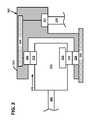
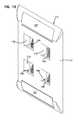
- FIG. 5is a rear perspective view of an example faceplate assembly with various components exploded away from each other;
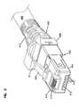
- FIG. 6is a front perspective view of the example faceplate assembly of FIG. 5 with the components assembled together;
- FIG. 7is a front elevational view of the faceplate assembly of FIG. 6 ;
- FIG. 8is a rear perspective view of the faceplate assembly of FIG. 6 ;
- FIG. 9is a rear elevational view of the faceplate assembly of FIG. 6 ;
- FIG. 10is a side elevational view of the faceplate assembly of FIG. 6 ;
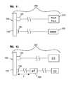
- FIG. 11is a schematic diagram of a first example managed connectivity system including the faceplate assembly of FIG. 6 ;
- FIG. 12is a schematic diagram of another example managed connectivity system including the faceplate assembly of FIG. 6 and a local processor;
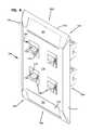
- FIG. 13is a front perspective view of an example faceplate member and circuit board assembly of the faceplate assembly of FIG. 6 ;
- FIG. 14is a front elevational view of the faceplate member and circuit board assembly of FIG. 13 ;
- FIG. 15is a rear perspective view of the faceplate member and circuit board assembly of FIG. 13 ;
- FIG. 16is a rear elevational view of the faceplate member and circuit board assembly of FIG. 13 ;
- FIG. 17is a side elevational view of the faceplate member and circuit board assembly of FIG. 13 ;
- FIG. 18is a front perspective view of an example circuit board assembly of the faceplate assembly of FIG. 6 ;
- FIG. 19is a front elevational view of the board assembly of FIG. 18 ;
- FIG. 20is a rear perspective view of the board assembly of FIG. 18 ;
- FIG. 21is a rear elevational view of the board assembly of FIG. 18 ;
- FIG. 22is a side elevational view of the board assembly of FIG. 18 ;
- FIG. 23is a front top perspective view of an example jack module of the faceplate assembly of FIG. 6 ;
- FIG. 24is a front, bottom perspective view of the example jack module of FIG. 23 .
- an example communications and data management systemincludes at least part of a communications network along which communications signals pass.
- Media segmentsconnect equipment of the communications network.
- Non-limiting examples of media segmentsinclude optical cables, electrical cables, and hybrid cables. This disclosure will focus on electrical media segments.
- the media segmentsmay be terminated with electrical plugs, electrical jacks, media converters, or other termination components.
- the communications and data management systemprovides physical layer information (PLI) functionality as well as physical layer management (PLM) functionality.
- PLI functionalityrefers to the ability of a physical component or system to identify or otherwise associate physical layer information with some or all of the physical components used to implement the physical layer of the system.
- PLM functionalityrefers to the ability of a component or system to manipulate or to enable others to manipulate the physical components used to implement the physical layer of the system (e.g., to track what is connected to each component, to trace connections that are made using the components, or to provide visual indications to a user at a selected component).
- physical layer informationrefers to information about the identity, attributes, and/or status of the physical components used to implement the physical layer of the communications system.
- Physical layer information of the communications systemcan include media information, device information, and location information.
- Media informationrefers to physical layer information pertaining to cables, plugs, connectors, and other such physical media.
- Non-limiting examples of media informationinclude a part number, a serial number, a plug type, a conductor type, a cable length, cable polarity, a cable pass-through capacity, a date of manufacture, a manufacturing lot number, the color or shape of the plug connector, an insertion count, and testing or performance information.
- Device informationrefers to physical layer information pertaining to the communications panels, inter-networking devices, media converters, computers, servers, wall outlets, and other physical communications devices to which the media segments attach.
- Location informationrefers to physical layer information pertaining to a physical layout of a building or buildings in which the network is deployed.
- one or more of the components (e.g., media segments, equipment, etc.) of the communications networkare configured to store physical layer information pertaining to the component as will be disclosed in more detail herein.
- Some componentsinclude media reading interfaces that are configured to read stored physical layer information from the components. The physical layer information obtained by the media reading interface may be communicated over the network for processing and/or storage.
- FIG. 1is a block diagram of one example implementation of a communications management system 200 that includes PLI functionality as well as PLM functionality.
- the management system 200comprises a plurality of connector assemblies 202 (e.g., patch panels, blades, optical adapters, electrical jacks, media converters, transceivers, etc.), connected to an IP network 218 .
- Each connector assembly 202includes one or more ports 204 , each of which is configured to receive a media segment for connection to other media segments or equipment of the management system 200 .
- electrical connector assemblies 202 and electrical media segmentswill be described. In other implementations, however, optical connector assemblies and media segments may be used.
- At least some of the connector assemblies 202are designed for use with electrical cables that have physical layer information stored in or on them.
- the physical layer informationis configured to be read by a programmable processor 206 associated with one or more connector assemblies 202 .
- the programmable processor 206communicates with memory of an electrical cable using a media reading interface 208 .
- each of the ports 204 of the connector assemblies 202includes a respective media reading interface 208 .
- a single media reading interface 208may correspond to two or more ports 204 .
- each connector assembly 202includes its own respective programmable processor 206 and its own respective network interface 216 that is used to communicatively couple that connector assembly 202 to an Internet Protocol (IP) network 218 .
- IPInternet Protocol
- connector assemblies 202are grouped together in proximity to each other (e.g., in a rack, rack system, patch panel, chassis, or equipment closet).
- Each connector assembly 202 of the groupincludes its own respective programmable processor 206 .
- not all of the connector assemblies 202include their own respective network interfaces 216 .
- some of the connector assemblies 202in the group include their own programmable processors 206 and network interfaces 216 , while others of the connector assemblies 202 (e.g., slaves”) do not include their own programmable processors 206 or network interfaces 216 .
- Each programmable processor 206is able to carry out the PLM functions for both the connector assembly 202 of which it is a part and any of the slave connector assemblies 202 to which the master connector assembly 202 is connected via the local connections.
- each of the connector assemblies 202 in a groupincludes its own “slave” programmable processors 206 .
- Each slave programmable processor 206is configured to manage the media reading interfaces 208 to determine if physical communication media segments are attached to the port 204 and to read the physical layer information stored in or on the attached physical communication media segments (if the attached segments have such information stored therein or thereon).
- Each of the slave programmable processors 206 in the groupalso is communicatively coupled to a common “master” programmable processor 217 .
- the master processor 217communicates the physical layer information read from by the slave processors 206 to devices that are coupled to the IP network 218 .
- the master programmable processor 217may be coupled to a network interface 216 that couples the master processor 217 to the IP network 218 .
- the communications management system 200includes functionality that enables the physical layer information captured by the connector assemblies 202 to be used by application-layer functionality outside of the traditional physical-layer management application domain.
- the management system 200may include an aggregation point 220 that is communicatively coupled to the connector assemblies 202 via the IP network 218 .
- the aggregation point 220can be implemented on a standalone network node or can be integrated along with other network functionality.
- the aggregation point 220includes functionality that obtains physical layer information from the connector assemblies 202 (and other devices) and stores the physical layer information in a data store.
- the aggregation point 220also can be used to obtain other types of physical layer information.
- this informationcan be provided to the aggregation point 220 , for example, by manually entering such information into a file (e.g., a spreadsheet) and then uploading the file to the aggregation point 220 (e.g., using a web browser) in connection with the initial installation of each of the various items.
- a filee.g., a spreadsheet
- Such informationcan also, for example, be directly entered using a user interface provided by the aggregation point 220 (e.g., using a web browser).
- the management system 200also may include a network management system (NMS) 230 includes PLI functionality 232 that is configured to retrieve physical layer information from the aggregation point 220 and provide it to the other parts of the NMS 230 for use thereby.
- the NMS 230uses the retrieved physical layer information to perform one or more network management functions.
- the NMS 230communicates with the aggregation point 220 over the IP network 218 .
- the NMS 230may be directly connected to the aggregation point 220 .
- An application 234 executing on a computer 236also can use the API implemented by the aggregation point 220 to access the PLI information maintained by the aggregation point 220 (e.g., to retrieve such information from the aggregation point 220 and/or to supply such information to the aggregation point 220 ).
- the computer 236is coupled to the IP network 218 and accesses the aggregation point 220 over the IP network 218 .
- One or more inter-networking devices 238 used to implement the IP network 218include physical layer information (PLI) functionality 240 .
- the PLI functionality 240 of the inter-networking device 238is configured to retrieve physical layer information from the aggregation point 220 and use the retrieved physical layer information to perform one or more inter-networking functions.
- Examples of inter-networking functionsinclude Layer 1, Layer 2, and Layer 3 (of the OSI model) inter-networking functions such as the routing, switching, repeating, bridging, and grooming of communication traffic that is received at the inter-networking device.
- example communications management system 200can be found in U.S. Publication No. 2011/0115494, filed Oct. 19, 2010, and titled “Managed Electrical Connectivity Systems,” the disclosure of which is hereby incorporated herein by reference.
- FIG. 2is a schematic diagram of one example connector assembly configured to collect physical layer information from a connector arrangement terminating a media segment.
- the connector assemblyis implemented as a jack module 320 and the connector arrangement is implemented as an electrical plug connector 310 .
- the plug connector 310terminates at least a first electrical media segment (e.g., a conductor cable) 305 and the jack module 320 terminates at least second electrical media segments (e.g., twisted pairs of copper wires) 329 .
- the jack module 320defines at least one socket port 325 in which the plug connector 310 can be accommodated.
- Each electrical segment 305 of the plug connector 310carries communication signals to primary contact members 312 on the plug connector 310 .
- the jack module 320includes a primary contact arrangement 322 that is accessible from the socket port 325 .
- the primary contact arrangement 322is aligned with and configured to interface with the primary contact members 312 to receive the communications signals from the primary contact members 312 when the plug connector 310 is inserted into the socket 325 of the jack module 320 .
- the jack module 320is electrically coupled to one or more printed circuit boards.
- the jack module 320can support or enclose a first printed circuit board 326 , which connects to insulation displacement contacts (IDCs) 327 or to another type of electrical contacts.
- the IDCs 327terminate the electrical segments 329 of physical communications media (e.g., conductive wires).
- the first printed circuit board 326manages the primary communication signals carried from the conductors terminating the cable 305 to the electrical segments 329 that couple to the IDCs 327 .
- the plug connector 310can include a storage device 315 configured to store physical layer information.
- the connector arrangement 310also includes second contact members 314 that are electrically coupled (i.e., or otherwise communicatively coupled) to the storage device 315 .
- the storage device 315is implemented using an EEPROM (e.g., a PCB surface-mount EEPROM). In other implementations, the storage device 315 is implemented using other non-volatile memory device. Each storage device 315 is arranged and configured so that it does not interfere or interact with the communications signals communicated over the media segment 305 .
- the jack module 320also includes a second contact arrangement (e.g., a media reading interface) 324 .
- the media reading interface 324is accessible through the socket port 325 .
- the second contact arrangement 324is aligned with and configured to interface with the second contact members 314 of the plug connector 310 to receive the physical layer information from the storage device 315 when the plug connector 310 is inserted into the socket 325 of the jack module 320 .
- the storage device interfaces 314 and the media reading interfaces 324each include three (3) leads—a power lead, a ground lead, and a data lead.
- the three leads of the storage device interface 314come into electrical contact with three (3) corresponding leads of the media reading interface 124 when the corresponding media segment is inserted in the corresponding port 325 .
- a two-line interfaceis used with a simple charge pump.
- additional leadscan be provided (e.g., for potential future applications).
- the jack module 320also can support, enclose, or otherwise be coupled to a second printed circuit board 328 , which connects to the second contact arrangement 324 .
- the second printed circuit board 328manages the physical layer information communicated from the storage device 315 through second contacts 314 , 324 .
- the second printed circuit board 328is positioned on an opposite side of the jack module 320 from the first printed circuit board 326 .
- the printed circuit boards 326 , 328can be positioned on the same side or on different sides.
- the second printed circuit board 328is positioned horizontally relative to the jack module 320 .
- the second printed circuit board 328is positioned vertically relative to the jack module 320 .
- the second printed circuit board 328can be communicatively connected to one or more programmable electronic processors (e.g., processor 206 of FIG. 1 ) and/or one or more network interfaces (e.g., interface 216 of FIG. 1 ).
- processors and interfacescan be arranged as components on the printed circuit board 328 .
- one of more such processor and interfacescan be arranged on a separate circuit board that is coupled to the second printed circuit board 328 .
- the second printed circuit board 328can couple to other circuit boards via a card edge type connection, a connector-to-connector type connection, a cable connection, etc.
- the network interfaceis configured to send the physical layer information to the data network.
- FIGS. 3 and 4show one example implementation of connector arrangement 400 in the form of an electrical plug connector 402 for terminating an electrical communications cable 490 .
- the plug connector 402is configured to be received within a port of a jack module (e.g., jack module 320 of FIG. 2 ).
- the plug connector 402is an RJ plug that is configured to connect to the end of a twisted pair copper cable 490 through an RJ jack (e.g., see jack block 120 of FIGS. 23 and 24 ).
- the plug connector 402includes a plug nose body 404 that can be attached to a wire manager 408 and/or a boot 410 .
- the plug nose body 404includes a finger tab 450 and a key member 415 at a first side 414 of the plug 402 .
- the plug nose body 404holds main signal contacts 412 at a second side 416 of the plug 402 .
- the main signal contacts 412are electrically connected to conductors (e.g., twisted pair conductors) of the communications cable 490 . Ribs 413 protect the main signal contacts 412 .
- the plug connector 402is configured to store physical layer information (e.g., an identifier and/or attribute information) pertaining to the electrical cable 490 terminated thereat.
- a storage device 430may be installed on or in the plug body 404 (see FIG. 4 ).
- the key member 415 of the plug nose body 404defines a cavity 460 ( FIG. 4 ) in which the storage device 430 can be stored.
- the plug 402includes a plug cover 406 that mounts on the plug nose body 404 to close the cavity 460 .
- Contact members 434 of the storage device 430are accessible through slots 446 in the key member 415 or plug cover 406 .
- the storage device 430includes a printed circuit board 420 .
- the circuit board 420can be slid or otherwise positioned along guides defined in the cavity 460 .
- the circuit board 420includes a substrate with conductive traces electrically connecting contacts and lands.
- the circuit board 420also includes circuit components, such as an EEPROM, at the lands.
- the storage device 430can include any suitable type of memory.
- the contact members 434permit connection of the EEPROM or other memory circuitry to a media reading interface of a coupler assembly as will be described herein. Additional details pertaining to the plug 402 can be found in U.S. Publication No. 2011/0115494 (incorporated by reference above).
- FIGS. 5-10illustrate one example faceplate assembly 100 configured to receive one or more plugs connectors 402 .
- the faceplate assembly 100includes a front 101 , a rear 102 , a top 103 , a bottom 104 , a first side 105 , and a second side 106 (see FIGS. 7 and 10 ).
- the faceplate assembly 100includes a faceplate member 110 that defines one or more openings 112 extending therethrough between the front 101 and rear 102 . In the example shown, the faceplate member 110 defines four openings 112 . In other implementations, the faceplate member 110 defines a greater or lesser number of openings 112 .
- a perimeter 111 of the faceplate member 110is tapered or contoured rearwardly.
- each jack module 120defines a port 122 that is accessible from the front 101 of the faceplate member 110 (see FIG. 6 ).
- the jack modules 120include one or more primary electrical contacts 125 ( FIG. 24 ) disposed within the port 122 and accessible from the front 101 of the faceplate member 110 when the jack 110 is mounted at the opening 112 .
- Each jack module 120also includes rear contacts 123 ( FIG. 8 ) that are coupled to the primary contacts 125 . The rear contacts 123 are accessible from the rear 102 of the faceplate member 110 (see FIG. 8 ).
- the jack modules 120may include optical connection structures (e.g., adapter sleeves) to enable optical coupling of optical fiber plug connectors at opposite sides of the jack module 120 .
- optical connection structurese.g., adapter sleeves
- electrical jack modules 120will be discussed herein with reference to the faceplate assembly 100 .
- a circuit board assembly 130also is mounted to the rear 102 of the faceplate member 110 .
- the circuit board assembly 130includes a circuit board 131 (e.g., a rigid printed circuit board, a flexible circuit board, etc.).
- One or more media reading interfaces 140are mounted to the circuit board assembly 130 .
- Each of the media reading interfaces 140includes one or more secondary contacts 145 that are electrically coupled to the circuit board 131 .
- a network connector 150also is coupled to the circuit board assembly 130 .
- the network connector 150is electrically connected to the secondary contacts 145 of each of the media reading interfaces 140 .
- the network connector 150includes network contacts that are accessible from the rear 102 of the faceplate member 110 for connection to the secondary contacts 145 .
- main signal contacts 412 of the plug 402engage the primary contacts 125 of the jack module 120 .
- Communications data signals carried over a cable to the plug 402are received via the main signal contacts 412 at the primary contacts 125 , through which the communications data signals reach the rear contacts 123 .
- the contact members 434 of the connector storage device 430engage the secondary contacts 145 of the media reading interface 140 .
- Management data signals from the connector storage device 430are received at the secondary contacts 145 , through which the management data signals reach the network connector 150 .
- the faceplate assembly 100can be secured to a wall or other surface using one or more fasteners 159 (e.g., a screw, a nail, a bolt, etc.).
- the faceplate member 110defines one or more fastener openings 118 that extend through the faceplate member 110 from the front 101 to the rear 102 .
- the faceplate member 110includes a first fastener opening 118 at a top 103 of the assembly 100 and a second fastener opening 118 at a bottom 104 of the assembly 100 .
- Each fastener opening 118is sized to receive at least one fastener 159 .
- the faceplate member 110is configured to engage the wall or other surface along a peripheral edge.
- the contoured perimeter 111 of the faceplate member 110has a depth D between a front surface of the faceplate member 110 and the peripheral edge. Accordingly, the depth D is the distance the front surface is offset from the wall or other surface to which the faceplate assembly 100 is secured.
- the depth Dis no more than about 0.3 inches. In certain implementations, the depth D is no more than about 0.27 inches. In certain implementations, the depth D is no more than about 0.24 inches. In certain implementations, the depth D is no more than about 0.23 inches. In certain implementations, the depth D is no more than about 0.22 inches.
- the fastener openings 118are recessed into the contoured perimeter 111 of the faceplate member 110 .
- the first fastener opening 118may be disposed at a first recessed region 113 defined in the top 103 of the perimeter 111 and the second fastener opening 118 may be disposed at a second recessed region 113 defined in the bottom 104 of the perimeter 111 (e.g., see FIG. 8 ).
- multiple fastener openings 118can be disposed at one or more of the recessed regions 113 .
- the recessed regions 113may be located elsewhere on the faceplate member 110 .
- a label arrangement 155mounts to the faceplate member 110 over the recessed region 113 to cover the fastener 159 seated in the recessed region 113 .
- the label arrangement 155is mounted over a recessed region 113 that does not define a fastener opening 118 .
- the label arrangement 155includes a label sheet 156 and a protective cover 157 .
- the label sheet 156is configured to receive a label (e.g., verbal or graphic indicia) that indicates the equipment to which the port connects, the type of plug to be received at the port, or other such information.
- the cover 157is sufficiently translucent that a user may view the label displayed on the label sheet through the cover 157 .
- the cover 157secures (e.g., latches, friction fits, snap-fits, etc.) the label sheet 156 to the faceplate member 110 .
- FIG. 11illustrates one example managed connectivity system 200 that includes at least one faceplate assembly 100 that is connected to termination equipment 210 (e.g., a patch panel, a switch, a router, etc.) and network analyzing equipment 220 .
- the termination equipment 210is configured to receive communications data signals from the jack modules 120 of the faceplate assembly 100 .
- the termination equipment 210receives communications data signals that were received at the primary contacts of the jack modules 120 .
- the network analyzing equipment 220is configured to receive management data signals from the network connector 150 of the faceplate assembly 100 .
- the network analyzing equipment 220receives management data signals that were received at the secondary contacts 145 of the media reading interfaces 140 .
- the termination equipment 210 and network analyzing equipment 220are located in the same general location (e.g., same room, same floor, etc.). In other implementations, the termination equipment 210 and network analyzing equipment 220 are located in different locations (e.g., different floors, different buildings, etc.). In some implementations, multiple faceplate assemblies are coupled to the same termination equipment 210 and/or network analyzer equipment 220 . In some implementations, the termination equipment 210 and network analyzing equipment 220 are located remote (e.g., different room, different floor, different building, etc.) from one or more of the faceplate assemblies 100 . For example, one or both of the termination equipment 210 and network analyzer 220 may be coupled to one or more of the faceplate assemblies 100 over a network connection. In other implementations, one or both of the termination equipment 210 and network analyzer 220 may be coupled to one or more of the faceplate assemblies 100 over a direct (e.g., wires, wireless, etc.) connection.
- a directe.g., wires,
- an electronic memory and processorare mounted to the faceplate assembly 100 .
- the electronic memory and processormay be mounted to the circuit board assembly 130 .
- the electronic memorymay store a unique ID that corresponds to the faceplate assembly as a whole.
- the processormay be configured to read the management data from the storage devices 430 of the plugs 402 received at the jack modules 120 .
- the processormay be configured to determine when the plug 402 is inserted and to read based on the insertion.
- FIG. 12illustrates one example managed connectivity system 250 that also includes at least one faceplate assembly 100 that is connected to termination equipment 210 (e.g., a patch panel, a switch, a router, etc.) and network analyzing equipment 220 .
- the termination equipment 210is configured to receive communications data signals from the jack modules 120 of the faceplate assembly 100 .
- the network analyzing equipment 220is electrically coupled to the network connector 150 of the faceplate assembly 100 .
- a local processor 260is electrically connected between the network connector 150 and the network analyzing equipment 220 .
- the local processor 260accesses the storage device 430 on the plug connector 402 via the network connector 150 and the secondary contacts 145 to obtain the management data signals.
- the local processor 260sends the management data to the network analyzer 220 .
- the local processor 260can detect an insertion of a plug 402 at the jack module 120 and reads the storage device 430 in response to the detected insertion.
- the termination equipment 210 and network analyzing equipment 220are located in the same general location (e.g., same room, same floor, etc.). In other implementations, the termination equipment 210 and network analyzing equipment 220 are located in different locations (e.g., different floors, different buildings, etc.).
- the local processor 260is disposed closer to the faceplate assembly 100 than the termination equipment 210 and network analyzing equipment 220 . In some implementations, the local processor 260 is located within fifty feet of the faceplate assembly 100 . In certain implementations, the local processor 260 is located within forty feet of the faceplate assembly 100 . In certain implementations, the local processor 260 is located within thirty feet of the faceplate assembly 100 . In certain implementations, the local processor 260 is located about twenty-five feet from the faceplate assembly 100 . For example, the local processor 260 may be located in a ceiling above a wall to which the faceplate assembly 100 is mounted.
- multiple faceplate assembliesare coupled to the same termination equipment 210 and/or network analyzer equipment 220 .
- one local processor 260can service multiple faceplate assemblies 100 .
- each faceplate assembly 100has its own local processor 260 .
- the termination equipment 210 and network analyzing equipment 220are located remote (e.g., different room, different floor, different building, etc.) from one or more of the faceplate assemblies 100 .
- one or both of the termination equipment 210 and network analyzer 220may be coupled to one or more of the faceplate assemblies 100 over a network connection.
- one or both of the termination equipment 210 and network analyzer 220may be coupled to one or more of the faceplate assemblies 100 over a direct (e.g., wires, wireless, etc.) connection.
- FIGS. 13-17illustrate one example implementation of a faceplate member 110 suitable for use in the faceplate assembly 100 disclosed herein.
- the faceplate member 110includes a front surface through which one or more openings 112 are defined.
- the front surfaceis generally flat.
- the front surfacedefines four openings 112 .
- the front surfacecan define a greater or lesser number of openings (e.g., one, two, six, etc.).
- the covers 157 of two label assemblies 155are shown mounted to the contoured peripheral edges 111 of the faceplate member 110 . As shown in FIGS. 15 and 16 , the covers 157 inhibit access to fasteners 151 extending through fastener openings 118 from the front 101 of the faceplate member 110 .
- the rear 102 of the faceplate member 110includes a rearwardly extending support frame 113 .
- the support frame 113extends around an outer perimeter of each opening 112 , thereby defining a depth for each opening 112 .
- the support frame 113extends rearwardly further than the contoured edges 111 .
- Recessed sections 115 , 116 , 117are defined in the support frame 113 to provide space to accommodate the circuit board assembly 130 as will be described in more detail herein.
- the recessed sections 115 - 117define continuous channels that extend through the support frame 113 .
- the recessed sections 115 - 117define cutouts in sections of the support frame 113 (e.g., see FIG. 5 ).
- a first recessed section 115extends through the support frame 113 in a top-bottom direction.
- the first recessed section 115may separate the openings 112 of the faceplate member 110 into left openings 112 and right openings 112 .
- the second and third recessed sections 116 , 117extend through the support frame 113 in a first side-second side direction.
- the second recessed section 116may separate the openings 112 of the faceplate member 112 into top openings 112 and bottom openings 112 .
- the third recessed section 117may extend through the support frame 113 either above the top openings 112 or below the bottom openings 112 (see FIG. 5 ).
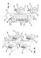
- FIGS. 18-22illustrate one example circuit board assembly 130 suitable for use in the faceplate assembly 100 disclosed herein.
- the circuit board assembly 130includes a printed circuit board 131 on which one or more media reading interfaces 140 are disposed.
- the printed circuit board 131is a rigid circuit board.
- the printed circuit board 131is a flexible circuit board.
- the circuit board 131is configured to mount to the rear 102 of the faceplate member 110 .
- the circuit board 131is configured to mount to the support frame 113 of the faceplate member 110 .
- the circuit board 131has a front face 137 and a rear face 138 .
- the front face 137faces the rear of the faceplate member 110 when the circuit board assembly 130 is mounted to the faceplate member 110 .
- the circuit board 131includes a main section 132 from which one or more segments branch off.
- the number of branched segmentsis equal to the number of openings 112 .
- openings 112may share branched segments.
- a first segment 133branches from the main section 132 towards a top, first side opening 112 ;
- a second segment 134branches from the main section 132 towards a top, second side opening 112 ;
- a third segment 135branches from the main section 132 towards a bottom, first side opening 112 ;
- a fourth segment 136branches from the main section 132 towards a bottom, second side opening 112 .
- each branched segment 133 - 136extends beneath and across one of the openings 112 (e.g., see FIGS. 15 and 16 ).
- a media reading interface 140is disposed at each opening 112 of the faceplate 110 .
- a media reading interface 140can be mounted over one or more of the branched segments 133 - 136 .
- a single media reading interface 140is mounted to each branch segment 133 - 136 .
- multiple media reading interfaces 140may be mounted to one or more of the branch segments 133 - 136 .
- Each media reading interface 140includes a body 141 that is configured to mount to the circuit board assembly 130 .
- the body 141is U-shaped and defines a notch 142 that is sized to receive one of the branched segments 133 - 136 .
- the body 141extends over the front face 137 , rear face 138 , and a side edge of the branched segment to retain the body 141 on the branched segment.
- a support ramp 144extends upwardly from the body 141 towards the rear face 138 of the circuit board 131 .
- the secondary contacts 145also extend upwardly from the body 141 .
- the secondary contacts 145extend into a corresponding opening 112 at which the media reading interface 140 is mounted.
- the secondary contacts 145are configured to flex rearwardly towards the support ramp 144 when a plug connector (e.g., plug 402 of FIGS. 3 and 4 ) is inserted through the corresponding opening 112 .
- the support ramp 144inhibits the secondary contacts 145 from flexing sufficiently far to be out of contact with the plug connector.
- the network connector 150is mounted to the circuit board assembly 130 .
- the network connector 150includes a connector body 151 that is mounted at the rear face 138 of the circuit board 131 .
- Rear contacts 152face rearwardly from the connector body 151 .
- Front contacts 153extend into/through the circuit board 131 (see FIG. 18 ).
- the network connector 150includes a D-block.
- the network connector 150can be any other type of connector (e.g., an RJ-11 connector, an RFID transceiver, etc.).
- the network connector 150includes rear and front contacts 152 , 153 that carry power, ground, and a data line for each media reading interface 140 .
- the network connector 150is isolated from the primary contacts 125 of the jack modules 120 .
- FIGS. 23 and 24illustrate one example implementation of a jack module 120 suitable for use in the faceplate assembly 100 disclosed herein.
- the jack module 120includes a jack body 121 that defines a socket or port 122 at one end thereof.
- the primary contacts 125are disposed within the jack body 121 . At least portions of the primary contacts 125 are accessible through the port 122 .
- the primary contacts 125flex away from the port 122 when a plug connector (e.g., plug 402 of FIGS. 3 and 4 ) is inserted into the port 122 .
- the main signal contacts 412 of the plug 402engage the primary contacts 125 when the plug 402 is held at the port 122 .
- a slot 129extends from the port along one side of the jack body 121 (see FIG. 24 ).
- Rear contacts 123are coupled to the primary contacts 125 .
- the rear contacts 123are accessible from another end of the jack body 121 .
- the rear contacts 123include insulation displacement contacts. In other implementations, however, the rear contacts 123 may include any other type of electrical connection.
- the rear contacts 123extend outwardly from a rear of the jack body 121 in-line with the port 122 . In other implementations, the rear contacts 123 may extend outwardly from any side of the jack body 121 and need not be in-line with the port 122 .
- the rear contacts 123are disposed in a separate housing part that latches to a first housing part that holds the primary contacts 125 .
- the jack body 121may be formed as a monolithic part.
- the jack body 121is configured to attach to the faceplate member 110 .
- the jack body 121includes latching lugs 124 at a first side of the body 121 and a latching arm 126 at a second side of the body 121 .
- the latching lugs 124are fixed relative to the body 121 and the latching arm 126 is flexible relative to the body 121 .
- the latching lugs 124include two ramped surfaces that define a channel therebetween.
- a portion 113 a ( FIG. 15 ) of the support frame 113 of the faceplate member 110fits in the channel (e.g., see FIGS. 8 and 10 ).
- the latching lugs 124extend across a width of the jack body 121 . In other implementations, however, multiple latching lugs 124 are arranged on the jack body 121 . For example, in FIG. 24 , two latching lugs 124 are spaced apart so as to be disposed at opposite sides of the jack body 121 .
- the latching arm 126also includes latching lugs 127 that are fixed relative to the latching arm 126 .
- the latching lugs 127include two ramped surfaces that define a channel therebetween. Another portion of the support frame 113 is configured to fit within the channel (e.g., see FIGS. 8 and 10 ).
- the latching arm 126also defines a ramped surface 128 that facilitates inserting a front portion of the jack body 121 through one of the openings 112 defined in the faceplate member 110 . In the example shown, the ramped surface 128 defines one of the two ramped surfaces of the latching lugs 127 .
- both ramped surfaces of the latching lugs 127extend across a width of the jack body 121 . In the example shown in FIG. 23 , however, one of the ramped surfaces includes a break or separation between two adjacent ramps.
- a front of the jack body 121is inserted through the support frame 113 and through one of the openings 112 from the rear 102 of the faceplate member 110 .
- the support frame 113deflects the latching arm 126 towards the jack body 121 .
- the jack body 121is angled or raised upwardly so that a front ramped surface of the latching lugs 124 clears the support frame 113 and the portion 113 a of the support frame 113 is allowed to enter the channel defined by the latching lugs 124 .
- the jack body 121is angled or further inserted through the opening 121 so that the latching arm 126 biases the latching lugs 127 into engagement with the other portion of the frame 113 , thereby securing the jack body 121 to the frame 113 .
- the secondary contacts 145 of the media reading interfaces 140extend into the jack modules 120 through the slots 129 .
- the circuit board assembly 130is mounted to the faceplate member 110 before the jack modules 120 . Since the slots 129 extend to the port 122 , the secondary contacts 145 slide through the ports 122 and through the slots 129 as the jack modules 120 are mounted to the faceplate member 110 .
- the front faces of the jack bodies 121are flush with the front surface of the faceplate member 110 when the jack modules 120 are fully inserted (e.g., see FIGS. 6 and 10 ). In other implementations, the front faces of the jack bodies 121 may be recessed rearwardly relative to the front surface of the faceplate member 110 or protruding outwardly from the front surface of the faceplate member 110 .
Landscapes
- Engineering & Computer Science (AREA)
- Microelectronics & Electronic Packaging (AREA)
- Computer Networks & Wireless Communication (AREA)
- Signal Processing (AREA)
- Manufacturing & Machinery (AREA)
- Details Of Connecting Devices For Male And Female Coupling (AREA)
Abstract
Description
Claims (10)
Priority Applications (2)
| Application Number | Priority Date | Filing Date | Title |
|---|---|---|---|
| US14/033,970US9203198B2 (en) | 2012-09-28 | 2013-09-23 | Low profile faceplate having managed connectivity |
| US14/946,916US9525255B2 (en) | 2012-09-28 | 2015-11-20 | Low profile faceplate having managed connectivity |
Applications Claiming Priority (2)
| Application Number | Priority Date | Filing Date | Title |
|---|---|---|---|
| US201261707242P | 2012-09-28 | 2012-09-28 | |
| US14/033,970US9203198B2 (en) | 2012-09-28 | 2013-09-23 | Low profile faceplate having managed connectivity |
Related Child Applications (1)
| Application Number | Title | Priority Date | Filing Date |
|---|---|---|---|
| US14/946,916ContinuationUS9525255B2 (en) | 2012-09-28 | 2015-11-20 | Low profile faceplate having managed connectivity |
Publications (2)
| Publication Number | Publication Date |
|---|---|
| US20140094059A1 US20140094059A1 (en) | 2014-04-03 |
| US9203198B2true US9203198B2 (en) | 2015-12-01 |
Family
ID=50385620
Family Applications (2)
| Application Number | Title | Priority Date | Filing Date |
|---|---|---|---|
| US14/033,970Expired - Fee RelatedUS9203198B2 (en) | 2012-09-28 | 2013-09-23 | Low profile faceplate having managed connectivity |
| US14/946,916Expired - Fee RelatedUS9525255B2 (en) | 2012-09-28 | 2015-11-20 | Low profile faceplate having managed connectivity |
Family Applications After (1)
| Application Number | Title | Priority Date | Filing Date |
|---|---|---|---|
| US14/946,916Expired - Fee RelatedUS9525255B2 (en) | 2012-09-28 | 2015-11-20 | Low profile faceplate having managed connectivity |
Country Status (2)
| Country | Link |
|---|---|
| US (2) | US9203198B2 (en) |
| WO (1) | WO2014052422A1 (en) |
Cited By (3)
| Publication number | Priority date | Publication date | Assignee | Title |
|---|---|---|---|---|
| US9525255B2 (en) | 2012-09-28 | 2016-12-20 | Commscope Technologies Llc | Low profile faceplate having managed connectivity |
| US10418756B2 (en)* | 2016-02-04 | 2019-09-17 | Harting (Zhuhai) Manufacturing Co., Ltd. | Plug connector with integrated galvanic separation and shielding element |
| US11226453B2 (en)* | 2017-08-09 | 2022-01-18 | Commscope Technologies Llc | Board mounted active component assembly |
Families Citing this family (11)
| Publication number | Priority date | Publication date | Assignee | Title |
|---|---|---|---|---|
| WO2011047281A1 (en) | 2009-10-16 | 2011-04-21 | Adc Telecommunications, Inc. | Managed connectivity in electrical systems and methods thereof |
| US9502830B2 (en) | 2014-12-03 | 2016-11-22 | Commscope, Inc. Of North Carolina | Multimedia faceplates having ethernet conversion circuitry |
| US10141127B2 (en)* | 2015-12-16 | 2018-11-27 | Abb Schweiz Ag | High-speed communications coupling for use in a circuit breaker assembly |
| USD799934S1 (en)* | 2016-09-22 | 2017-10-17 | Crestron Electronics, Inc. | Wall mounted receptacle |
| USD797545S1 (en)* | 2016-09-22 | 2017-09-19 | Crestron Electronics, Inc. | Wall mounted jack panel |
| US9912102B1 (en)* | 2016-11-29 | 2018-03-06 | Leviton Manufacturing Co., Inc. | Limited power outlet with changeable protective bezel |
| TWI642236B (en)* | 2017-08-02 | 2018-11-21 | 定逸工業股份有限公司 | Electrical connector for network cables |
| US12327948B2 (en) | 2019-09-30 | 2025-06-10 | Commscope Technologies Llc | High density coupling panel |
| WO2021067274A1 (en) | 2019-09-30 | 2021-04-08 | Commscope Technologies Llc | Couplers for single pair connectors |
| US12199372B2 (en) | 2021-02-26 | 2025-01-14 | Commscope Technologies Llc | Couplers for single pair connectors |
| US20240396256A1 (en)* | 2021-09-21 | 2024-11-28 | Commscope Technologies Llc | Single-pair ethernet mount housing |
Citations (162)
| Publication number | Priority date | Publication date | Assignee | Title |
|---|---|---|---|---|
| US3243761A (en) | 1963-10-08 | 1966-03-29 | Burndy Corp | Contact locking connector |
| US4127317A (en) | 1976-07-06 | 1978-11-28 | Bunker Ramo Corporation | Electrical connectors which may be shortened to provide fewer contacts |
| US4953194A (en) | 1989-09-22 | 1990-08-28 | Network Devices, Incorporated | Automated documentation system for a communications network |
| US4968929A (en) | 1987-04-18 | 1990-11-06 | Heidelberger Druckmaschinen Ag | Plug connector coding system for electric cables |
| US5030123A (en) | 1989-03-24 | 1991-07-09 | Adc Telecommunications, Inc. | Connector and patch panel for digital video and data |
| US5052940A (en) | 1990-05-11 | 1991-10-01 | Rit-Rad Interconnection Technologies Ltd. | Hermaphroditic self-shorting electrical connector |
| US5107532A (en) | 1989-09-22 | 1992-04-21 | Cable Management International, Inc. | Automated documentation system for a communications network |
| US5161988A (en) | 1991-02-13 | 1992-11-10 | Rit Technologies Ltd. | Patching panel |
| US5166970A (en) | 1991-06-10 | 1992-11-24 | Ward Timothy K | Multi-conductor identifier with voice communication capability |
| US5197895A (en) | 1991-05-10 | 1993-03-30 | Bicore Monitoring Systems | Disposable electro-fluidic connector with data storage |
| US5222164A (en) | 1992-08-27 | 1993-06-22 | International Business Machines Corporation | Electrically isolated optical connector identification system |
| US5265187A (en) | 1992-10-28 | 1993-11-23 | Northern Telecom Limited | Distribution frame and optical connector holder combination |
| US5305405A (en) | 1993-02-25 | 1994-04-19 | Adc Telecommunications, Inc. | Patch cord |
| US5353367A (en) | 1993-11-29 | 1994-10-04 | Northern Telecom Limited | Distribution frame and optical connector holder combination |
| US5382182A (en) | 1993-05-28 | 1995-01-17 | Apple Computer, Inc. | Special purpose modular connector plug |
| US5394503A (en) | 1993-10-08 | 1995-02-28 | Data Switch Corporation | Optical fiber connection monitoring apparatus, patch panel control system and method of using same |
| US5393249A (en) | 1993-06-30 | 1995-02-28 | Adc Telecommunications, Inc. | Rear cross connect DSX system |
| US5413494A (en) | 1992-10-05 | 1995-05-09 | Adc Telecommunications, Inc. | Jack module assembly |
| US5415570A (en) | 1992-12-28 | 1995-05-16 | At&T Corp. | Modular connector with contacts associated with more than one surface |
| US5418334A (en) | 1993-08-04 | 1995-05-23 | Williams; Kenyon D. | Relative position tracer lamp indicator |
| US5419717A (en) | 1994-08-15 | 1995-05-30 | The Whitaker Corporation | Hybrid connector between optics and edge card |
| US5448675A (en) | 1994-06-09 | 1995-09-05 | At&T Ipm Corp. | Telecommunications distribution frame with tracing |
| US5467062A (en) | 1992-04-02 | 1995-11-14 | Adc Telecommunications, Inc. | Miniature coax jack module |
| US5470251A (en) | 1993-09-24 | 1995-11-28 | Molex Incorporated | Connector engagement detecting device |
| US5473715A (en) | 1994-05-03 | 1995-12-05 | Methode Electronics, Inc. | Hybrid fiber optic/electrical connector |
| US5483467A (en) | 1992-06-10 | 1996-01-09 | Rit Technologies, Ltd. | Patching panel scanner |
| US5660567A (en) | 1995-11-14 | 1997-08-26 | Nellcor Puritan Bennett Incorporated | Medical sensor connector with removable encoding device |
| US5674085A (en) | 1996-05-24 | 1997-10-07 | The Whitaker Corporation | Electrical connector with switch |
| US5685741A (en) | 1996-06-27 | 1997-11-11 | Adc Telecommunications, Inc. | On demand plug-in jack card and monitor frame |
| US5704797A (en) | 1994-05-19 | 1998-01-06 | Tii Industries, Inc. | Switchable electrical socket |
| US5712942A (en) | 1996-05-13 | 1998-01-27 | Lucent Technologies Inc. | Optical communications system having distributed intelligence |
| US5800192A (en) | 1996-08-30 | 1998-09-01 | Berg Technology, Inc. | Receptacle with integral sensor device |
| US5821510A (en) | 1994-12-22 | 1998-10-13 | Lucent Technologies Inc. | Labeling and tracing system for jumper used in an exchange |
| US5854824A (en) | 1994-09-04 | 1998-12-29 | Rit Technologies Ltd. | Connectivity scanner |
| US5871368A (en) | 1996-11-19 | 1999-02-16 | Intel Corporation | Bus connector |
| US5910776A (en) | 1994-10-24 | 1999-06-08 | Id Technologies, Inc. | Method and apparatus for identifying locating or monitoring equipment or other objects |
| US6002331A (en) | 1998-07-20 | 1999-12-14 | Laor; Herzel | Method and apparatus for identifying and tracking connections of communication lines |
| US6095851A (en) | 1997-11-17 | 2000-08-01 | Xircom, Inc. | Status indicator for electronic device |
| US6116961A (en) | 1998-11-12 | 2000-09-12 | Adc Telecommunications, Inc. | Jack assembly |
| WO2000065696A1 (en) | 1999-04-23 | 2000-11-02 | The Whitaker Corporation | Receptacle connector with plug differentiation member |
| US6222975B1 (en) | 1998-12-11 | 2001-04-24 | Lucent Technologies, Inc. | System and method for detecting and reporting the use of optical fibers in fiber optic cables |
| US6222908B1 (en) | 1999-09-23 | 2001-04-24 | Avaya Technology Corp. | Method and device for identifying a specific patch cord connector as it is introduced into, or removed from, a telecommunications patch system |
| US6227911B1 (en) | 1998-09-09 | 2001-05-08 | Amphenol Corporation | RJ contact/filter modules and multiport filter connector utilizing such modules |
| US6234830B1 (en) | 1999-02-10 | 2001-05-22 | Avaya Technology Corp. | Tracing interface module for patch cords in a telecommunications system |
| US6238235B1 (en) | 1999-05-10 | 2001-05-29 | Rit Technologies Ltd. | Cable organizer |
| US6244908B1 (en) | 2000-08-04 | 2001-06-12 | Thomas & Betts International, Inc. | Switch within a data connector jack |
| US6280231B1 (en) | 1998-07-24 | 2001-08-28 | Krone Aktiengesellschaft | Electrical connector |
| US6285293B1 (en) | 1999-02-10 | 2001-09-04 | Avaya Technology Corp. | System and method for addressing and tracing patch cords in a dedicated telecommunications system |
| US6300877B1 (en) | 2000-03-10 | 2001-10-09 | Adc Telecommunications, Inc. | DSX baytracer illuminator |
| US6330307B1 (en) | 1999-02-10 | 2001-12-11 | Avaya Technology Corp. | Display panel overlay structure and method for tracing interface modules in a telecommunications patch system |
| US6330148B1 (en) | 1999-01-13 | 2001-12-11 | Lg. Philips Lcd Co., Ltd. | Flat panel display module for computer |
| US20020008613A1 (en) | 2000-02-11 | 2002-01-24 | Nathan John F. | Electrical connector for vehicle wiring |
| US6350148B1 (en) | 1999-02-10 | 2002-02-26 | Avaya Technology Corp. | Method and device for detecting the presence of a patch cord connector in a telecommunications patch system |
| US6364694B1 (en) | 2001-01-19 | 2002-04-02 | M M E Corporation | Modular communications socket |
| US6371780B1 (en) | 2000-05-15 | 2002-04-16 | Avaya Technology Corp. | RJ jack with switch |
| WO2002047215A1 (en) | 2000-12-06 | 2002-06-13 | Barkey, Volker | Electrical device |
| US6421322B1 (en) | 1997-11-17 | 2002-07-16 | Adc Telecommunications, Inc. | System and method for electronically identifying connections of a cross-connect system |
| US6424710B1 (en) | 1999-02-10 | 2002-07-23 | Avaya Technology Corp. | Method and device for detecting the presence of a patch cord connector in a telecommunications patch system using passive detection sensors |
| US6422895B1 (en) | 2001-04-17 | 2002-07-23 | M M E Corporation | Receptacle for telephone plug and wide-band cable plug |
| US6431892B1 (en) | 1999-08-31 | 2002-08-13 | 3Com Corporation | Electrical connector with automatic switching between multiple devices |
| US6456768B1 (en) | 2000-10-18 | 2002-09-24 | Fitel Usa Corp. | Optical fiber cable tracing system |
| USD466479S1 (en) | 2000-05-25 | 2002-12-03 | Krone Gmbh | RJ style plug |
| US6499861B1 (en) | 1999-09-23 | 2002-12-31 | Avaya Technology Corp. | Illuminated patch cord connector ports for use in a telecommunications patch closet having patch cord tracing capabilities |
| US6511231B2 (en) | 2000-12-27 | 2003-01-28 | Fitel Usa Corp. | Optical connector receptacle having switching capability |
| US6522737B1 (en) | 1999-02-10 | 2003-02-18 | Avaya Technology Corp. | System and method of operation for a telecommunications patch system |
| US6554484B2 (en) | 2000-12-27 | 2003-04-29 | Fitel Usa Corp. | Optical connector receptacle having switching capability |
| US6574586B1 (en) | 1999-04-06 | 2003-06-03 | Itracs Corporation | System for monitoring connection pattern of data ports |
| US6612856B1 (en) | 2001-12-17 | 2003-09-02 | 3Com Corporation | Apparatus and methods for preventing cable-discharge damage to electronic equipment |
| US6626697B1 (en) | 2002-11-07 | 2003-09-30 | Tyco Electronics Corp. | Network connection sensing assembly |
| US6641443B1 (en) | 2002-09-27 | 2003-11-04 | Leviton Manufacturing Co., Inc. | Electrical connector jack |
| US6663436B1 (en) | 2002-01-23 | 2003-12-16 | Avaya Technology Corp. | High frequency telecommunication connector |
| US6684179B1 (en) | 1999-04-06 | 2004-01-27 | Itracs Corporation | System for monitoring connection pattern of data ports |
| DE10244304B3 (en) | 2002-09-23 | 2004-03-18 | Data-Complex E.K. | Arrangement for monitoring patch panels at distributor points in data networks has patch cables that can be plugged into connections in patch fields with plugs, each fitted with a transponder |
| US20040052498A1 (en) | 2002-09-13 | 2004-03-18 | Colombo Bruce A. | Adapter systems for dynamically updating information related to a network and methods for developing the adapter systems |
| US6743044B2 (en) | 2002-08-14 | 2004-06-01 | Adc Telecommunications, Inc. | Cross-connect jumper assembly having tracer lamp |
| US6780035B2 (en) | 2001-03-12 | 2004-08-24 | Nordx/Cdt, Inc. | Electrostatic discharge protected jack |
| US6786776B2 (en) | 2002-09-27 | 2004-09-07 | Leviton Manufacturing Co., Inc. | Electrical connector jack |
| US6793408B2 (en) | 2002-12-31 | 2004-09-21 | Intel Corporation | Module interface with optical and electrical interconnects |
| JP2004281404A (en) | 2003-03-14 | 2004-10-07 | Tyco Electronics Corp | Electric coupler |
| US6802735B2 (en) | 2002-06-18 | 2004-10-12 | Tyco Electronics Corporation | Receptacle and plug interconnect module with integral sensor contacts |
| US6808116B1 (en) | 2002-05-29 | 2004-10-26 | At&T Corp. | Fiber jumpers with data storage method and apparatus |
| US6811446B1 (en) | 2003-10-08 | 2004-11-02 | Speed Thch Corp. | Combination connector shell |
| US6814624B2 (en) | 2002-11-22 | 2004-11-09 | Adc Telecommunications, Inc. | Telecommunications jack assembly |
| US20040240807A1 (en) | 2001-05-30 | 2004-12-02 | Franz-Friedrich Frohlich | Optical distribution device and light waveguide connector cable |
| US6850685B2 (en) | 2002-03-27 | 2005-02-01 | Adc Telecommunications, Inc. | Termination panel with pivoting bulkhead and cable management |
| US6932517B2 (en) | 2000-10-27 | 2005-08-23 | Ethicon Endo-Surgery, Inc. | Connector incorporating a contact pad surface on a plane parallel to a longitudinal axis |
| US6939168B2 (en) | 2001-07-06 | 2005-09-06 | Fci Americas Technology, Inc. | Universal serial bus electrical connector |
| USD510068S1 (en) | 2002-03-11 | 2005-09-27 | Rit Technologies Ltd | Patch panel for communication equipment |
| US6961675B2 (en) | 2000-03-14 | 2005-11-01 | Itracs Corporation | System for monitoring connection pattern of data ports |
| US6971895B2 (en) | 2002-11-15 | 2005-12-06 | Tokyo Communication Equipment Mfg Co., Ltd. | Connector adapter with memory function unit |
| US6976867B2 (en) | 2002-11-07 | 2005-12-20 | Tyco Electronics Amp Espana, S.A. | Network connection sensing assembly |
| DE102004033940A1 (en) | 2004-07-14 | 2006-02-16 | Tkm Telekommunikation Und Elektronik Gmbh | Connector identification system for identifying multi-pole plug-in connectors for data-transmission cables in panels with manifold sockets has detectors/LEDs assigned to individual sockets |
| US7077710B2 (en) | 2001-03-21 | 2006-07-18 | Rit Technologies Ltd. | Patch panel |
| US20060160395A1 (en) | 2004-12-21 | 2006-07-20 | Commscope Solutions Properties, Llc | Methods, systems and computer program products for connecting and monitoring network equipment in a telecommunications system |
| US7081808B2 (en) | 2002-09-13 | 2006-07-25 | Fitel Usa Corp. | Self-registration systems and methods for dynamically updating information related to a network |
| US7112090B2 (en) | 2003-05-14 | 2006-09-26 | Panduit Corp. | High density keystone jack patch panel |
| US7123810B2 (en) | 2004-05-04 | 2006-10-17 | Bellsouth Intellectual Property Corporation | Optical fiber connectors with identification circuits and distribution terminals that communicate therewith |
| US20060234564A1 (en) | 2005-04-15 | 2006-10-19 | Broadcom Corporation | System and method for detecting an incorrect cable connection |
| US7153142B2 (en) | 2002-11-11 | 2006-12-26 | Rit Technologies Ltd. | Retrofit kit for interconnect cabling system |
| US7165728B2 (en) | 2004-04-02 | 2007-01-23 | Stratos International, Inc. | Radio frequency identification for transfer of component information in fiber optic testing |
| US7193422B2 (en) | 2004-01-20 | 2007-03-20 | The Siemon Company | Patch panel system |
| US7207819B2 (en) | 2005-09-09 | 2007-04-24 | Hon Hai Precision Ind. Co., Ltd. | Electrical connector with a detective switch |
| US7210858B2 (en) | 2002-01-15 | 2007-05-01 | Tokyo Communications Equipment Co., Ltd. | Optical connector with memory function |
| US7226217B1 (en) | 2005-11-18 | 2007-06-05 | Stratos International, Inc. | Transceiver/fiber optic connector adaptor with patch cord ID reading capability |
| US7234944B2 (en) | 2005-08-26 | 2007-06-26 | Panduit Corp. | Patch field documentation and revision systems |
| US7241157B2 (en) | 2004-04-09 | 2007-07-10 | Hon Hai Precision Ind. Co., Ltd. | Modular jack with a detective switch |
| US20070237470A1 (en) | 2006-04-10 | 2007-10-11 | Aronson Lewis B | Active optical cable with electrical connector |
| US20070254529A1 (en) | 2006-04-26 | 2007-11-01 | Tyco Electronics Corporation | Electrical connector having contact plates |
| US7297018B2 (en) | 2004-11-03 | 2007-11-20 | Panduit Corp. | Method and apparatus for patch panel patch cord documentation and revision |
| US7312715B2 (en) | 2003-07-31 | 2007-12-25 | Rit Technologies Ltd. | Management of large scale cabling systems |
| US7314393B2 (en) | 2005-05-27 | 2008-01-01 | Commscope, Inc. Of North Carolina | Communications connectors with floating wiring board for imparting crosstalk compensation between conductors |
| US7315224B2 (en) | 2001-08-23 | 2008-01-01 | Rit Technologies Ltd. | High data rate interconnecting device |
| USD559186S1 (en) | 2004-09-20 | 2008-01-08 | Rit Technologies Ltd. | High-density patch panel |
| US7352289B1 (en) | 2003-09-11 | 2008-04-01 | Sun Microsystems, Inc. | System and method for detecting the connection state of a network cable connector |
| US20080090454A1 (en) | 2006-10-10 | 2008-04-17 | Adc Telecommunications, Inc. | Upgradeable patch panel |
| US20080100467A1 (en) | 2006-10-31 | 2008-05-01 | Downie John D | Radio frequency identification of component connections |
| US7370106B2 (en) | 2000-11-22 | 2008-05-06 | Panduit Corp. | Network revision system with local system ports |
| US7384300B1 (en) | 1999-12-22 | 2008-06-10 | Xerox Corporation | Method and apparatus for a connection sensing apparatus |
| US7396245B2 (en) | 2006-10-13 | 2008-07-08 | Cheng Uei Precision Industry Co., Ltd. | Memory card connector |
| US7497709B1 (en) | 2007-09-12 | 2009-03-03 | Hon Hai Precision Ind. Co., Ltd. | Electrical connector with switch device |
| US7519000B2 (en) | 2002-01-30 | 2009-04-14 | Panduit Corp. | Systems and methods for managing a network |
| US20090097846A1 (en) | 2006-12-14 | 2009-04-16 | David Robert Kozischek | RFID Systems and Methods for Optical Fiber Network Deployment and Maintenance |
| US7534137B2 (en) | 2006-02-14 | 2009-05-19 | Panduit Corp. | Method and apparatus for patch panel patch cord documentation and revision |
| US7552872B2 (en) | 2006-06-21 | 2009-06-30 | Opnext Japan, Inc. | Reader/writer, optical transceiver module, and cable system |
| US20090166404A1 (en) | 2008-01-02 | 2009-07-02 | Commscope, Inc. Of North Carolina | Intelligent MPO-to-MPO Patch Panels Having Connectivity Tracking Capabilities and Related Methods |
| US7563116B2 (en) | 2007-09-22 | 2009-07-21 | Hon Hai Precision Ind. Co., Ltd. | Electrical connector with switching terminals |
| US7570861B2 (en) | 2007-01-19 | 2009-08-04 | Adc Telecommunications, Inc. | Adapter panel with lateral sliding adapter arrays |
| US7575454B1 (en) | 2008-06-05 | 2009-08-18 | Taiko Denki Co., Ltd. | Receptacle and mounting structure thereof |
| US7588470B2 (en) | 2007-09-18 | 2009-09-15 | Hon Hai Precision Ind. Co., Ltd. | Electrical connector with an improved detecting pin |
| US20090232455A1 (en) | 2008-03-04 | 2009-09-17 | Ponharith Pon Nhep | Multi-port adapter block |
| US7591667B2 (en) | 2005-03-04 | 2009-09-22 | Tyco Electronics Amp Espana Sa | Network connection sensing assembly |
| US7607926B2 (en) | 2008-03-14 | 2009-10-27 | Advanced Connectek Inc. | Connector with a switch terminal |
| US20090311916A1 (en) | 2007-05-07 | 2009-12-17 | Ortronics, Inc | Subassembly containing contact leads |
| US7635280B1 (en) | 2008-07-30 | 2009-12-22 | Apple Inc. | Type A USB receptacle with plug detection |
| WO2010001400A1 (en) | 2008-07-02 | 2010-01-07 | Rit Technologies Ltd. | System and method for monitoring physical layer connectivity |
| US7648377B2 (en) | 2007-07-31 | 2010-01-19 | Japan Aviation Electronics Industry, Limited | Connector having connection detecting means which is elastically deformable |
| DE102008034261A1 (en) | 2008-07-14 | 2010-01-21 | Tkm Telekommunikation Und Elektronik Gmbh | Plug connector i.e. RJ45-plug connector, for electrical data transmission cable, has springy latching element arranged at rear edge of block, where radio frequency identification transponder is accommodated in front side drilling in block |
| US20100048064A1 (en) | 2008-08-19 | 2010-02-25 | John Peng | Network jack and processing method for the same |
| US7682174B2 (en) | 2007-08-28 | 2010-03-23 | Hon Hai Precision Ind. Co., Ltd. | Electrical card connector |
| DE102008052857A1 (en) | 2008-10-23 | 2010-04-29 | Kem-Gmbh | Device for network connection for transferring data and supply current, has plug connecting unit with detecting medium, where release of connections is detected by detected medium |
| US7722370B2 (en) | 2007-12-28 | 2010-05-25 | Asustek Computer Inc. | Socket with detection functions |
| US7727026B2 (en) | 2007-10-12 | 2010-06-01 | Hon Hai Precision Ind. Co., Ltd. | Electrical connector with a pair of improved detecting pins |
| WO2010081186A1 (en) | 2009-01-19 | 2010-07-22 | Adc Gmbh | Telecommunications connector |
| US20100211665A1 (en) | 2009-02-13 | 2010-08-19 | Adc Telecommunications, Inc. | Network management systems for use with physical layer information |
| US7798832B2 (en) | 2007-09-03 | 2010-09-21 | Hon Hai Precision Ind. Co., Ltd | Electrical connector with a pair of improved detacting pins |
| US7811119B2 (en) | 2005-11-18 | 2010-10-12 | Panduit Corp. | Smart cable provisioning for a patch cord management system |
| WO2010121639A1 (en) | 2009-04-22 | 2010-10-28 | Adc Gmbh | Method and arrangement for identifying at least one object |
| US7867017B1 (en) | 2009-11-20 | 2011-01-11 | U.D. Electronic Corp. | Connector insertion sensing structure |
| US7869426B2 (en) | 2006-03-22 | 2011-01-11 | Adc Gmbh | Intelligent patching system and method |
| US7872738B2 (en) | 2005-08-22 | 2011-01-18 | Tyco Electronics Subsea Communications Llc | System and method for monitoring an optical communication system |
| US7914310B2 (en) | 2007-10-29 | 2011-03-29 | Sony Ericsson Mobile Communications Ab | Universal serial bus connector with antenna capabilities |
| US20110115494A1 (en) | 2009-10-19 | 2011-05-19 | Adc Telecommunications | Managed electrical connectivity systems |
| US20110228473A1 (en) | 2010-02-12 | 2011-09-22 | Chad Anderson | Communications bladed panel systems |
| US20120003877A1 (en) | 2010-07-02 | 2012-01-05 | Baudouin Bareel | Communication assembly comprising a plug connector and a jack assembly provided to be connected |
| US8157582B2 (en) | 2009-04-02 | 2012-04-17 | The Siemon Company | Telecommunications patch panel |
| US20120184141A1 (en) | 2010-10-22 | 2012-07-19 | Adc Telecommunications, Inc. | Contact set arrangement for right angle jack |
| US8282425B2 (en) | 2009-08-25 | 2012-10-09 | Tyco Electronics Corporation | Electrical connectors having open-ended conductors |
| US8287316B2 (en) | 2009-08-25 | 2012-10-16 | Tyco Electronics Corporation | Electrical connector with separable contacts |
| US20120322310A1 (en) | 2011-04-15 | 2012-12-20 | Chris Taylor | Managed electrical connectivity systems |
| US8408926B1 (en) | 2010-12-01 | 2013-04-02 | Nai-Chien Chang | Network connector with switch function |
| US8992260B2 (en)* | 2009-10-16 | 2015-03-31 | Adc Telecommunications, Inc. | Managed connectivity in electrical systems and methods thereof |
| US8992261B2 (en)* | 2010-10-22 | 2015-03-31 | Adc Telecommunications, Inc. | Single-piece plug nose with multiple contact sets |
Family Cites Families (1)
| Publication number | Priority date | Publication date | Assignee | Title |
|---|---|---|---|---|
| US9203198B2 (en) | 2012-09-28 | 2015-12-01 | Commscope Technologies Llc | Low profile faceplate having managed connectivity |
- 2013
- 2013-09-23USUS14/033,970patent/US9203198B2/ennot_activeExpired - Fee Related
- 2013-09-25WOPCT/US2013/061629patent/WO2014052422A1/enactiveApplication Filing
- 2015
- 2015-11-20USUS14/946,916patent/US9525255B2/ennot_activeExpired - Fee Related
Patent Citations (180)
| Publication number | Priority date | Publication date | Assignee | Title |
|---|---|---|---|---|
| US3243761A (en) | 1963-10-08 | 1966-03-29 | Burndy Corp | Contact locking connector |
| US4127317A (en) | 1976-07-06 | 1978-11-28 | Bunker Ramo Corporation | Electrical connectors which may be shortened to provide fewer contacts |
| US4968929A (en) | 1987-04-18 | 1990-11-06 | Heidelberger Druckmaschinen Ag | Plug connector coding system for electric cables |
| US5030123A (en) | 1989-03-24 | 1991-07-09 | Adc Telecommunications, Inc. | Connector and patch panel for digital video and data |
| US5107532A (en) | 1989-09-22 | 1992-04-21 | Cable Management International, Inc. | Automated documentation system for a communications network |
| US4953194A (en) | 1989-09-22 | 1990-08-28 | Network Devices, Incorporated | Automated documentation system for a communications network |
| US5052940A (en) | 1990-05-11 | 1991-10-01 | Rit-Rad Interconnection Technologies Ltd. | Hermaphroditic self-shorting electrical connector |
| US5161988A (en) | 1991-02-13 | 1992-11-10 | Rit Technologies Ltd. | Patching panel |
| US5197895A (en) | 1991-05-10 | 1993-03-30 | Bicore Monitoring Systems | Disposable electro-fluidic connector with data storage |
| US5166970A (en) | 1991-06-10 | 1992-11-24 | Ward Timothy K | Multi-conductor identifier with voice communication capability |
| US5467062A (en) | 1992-04-02 | 1995-11-14 | Adc Telecommunications, Inc. | Miniature coax jack module |
| US5483467A (en) | 1992-06-10 | 1996-01-09 | Rit Technologies, Ltd. | Patching panel scanner |
| US5222164A (en) | 1992-08-27 | 1993-06-22 | International Business Machines Corporation | Electrically isolated optical connector identification system |
| US5413494A (en) | 1992-10-05 | 1995-05-09 | Adc Telecommunications, Inc. | Jack module assembly |
| US5265187A (en) | 1992-10-28 | 1993-11-23 | Northern Telecom Limited | Distribution frame and optical connector holder combination |
| US5415570A (en) | 1992-12-28 | 1995-05-16 | At&T Corp. | Modular connector with contacts associated with more than one surface |
| US5305405A (en) | 1993-02-25 | 1994-04-19 | Adc Telecommunications, Inc. | Patch cord |
| US5382182A (en) | 1993-05-28 | 1995-01-17 | Apple Computer, Inc. | Special purpose modular connector plug |
| US5393249A (en) | 1993-06-30 | 1995-02-28 | Adc Telecommunications, Inc. | Rear cross connect DSX system |
| US5418334A (en) | 1993-08-04 | 1995-05-23 | Williams; Kenyon D. | Relative position tracer lamp indicator |
| US5470251A (en) | 1993-09-24 | 1995-11-28 | Molex Incorporated | Connector engagement detecting device |
| US5394503A (en) | 1993-10-08 | 1995-02-28 | Data Switch Corporation | Optical fiber connection monitoring apparatus, patch panel control system and method of using same |
| US5353367A (en) | 1993-11-29 | 1994-10-04 | Northern Telecom Limited | Distribution frame and optical connector holder combination |
| US5473715A (en) | 1994-05-03 | 1995-12-05 | Methode Electronics, Inc. | Hybrid fiber optic/electrical connector |
| US5704797A (en) | 1994-05-19 | 1998-01-06 | Tii Industries, Inc. | Switchable electrical socket |
| US5448675A (en) | 1994-06-09 | 1995-09-05 | At&T Ipm Corp. | Telecommunications distribution frame with tracing |
| US5419717A (en) | 1994-08-15 | 1995-05-30 | The Whitaker Corporation | Hybrid connector between optics and edge card |
| US5854824A (en) | 1994-09-04 | 1998-12-29 | Rit Technologies Ltd. | Connectivity scanner |
| US5910776A (en) | 1994-10-24 | 1999-06-08 | Id Technologies, Inc. | Method and apparatus for identifying locating or monitoring equipment or other objects |
| US5821510A (en) | 1994-12-22 | 1998-10-13 | Lucent Technologies Inc. | Labeling and tracing system for jumper used in an exchange |
| US5660567A (en) | 1995-11-14 | 1997-08-26 | Nellcor Puritan Bennett Incorporated | Medical sensor connector with removable encoding device |
| US5712942A (en) | 1996-05-13 | 1998-01-27 | Lucent Technologies Inc. | Optical communications system having distributed intelligence |
| US5674085A (en) | 1996-05-24 | 1997-10-07 | The Whitaker Corporation | Electrical connector with switch |
| US5685741A (en) | 1996-06-27 | 1997-11-11 | Adc Telecommunications, Inc. | On demand plug-in jack card and monitor frame |
| US6095837A (en) | 1996-08-30 | 2000-08-01 | Berg Technology, Inc. | Electrical connector with integral sensor device |
| US5800192A (en) | 1996-08-30 | 1998-09-01 | Berg Technology, Inc. | Receptacle with integral sensor device |
| US5871368A (en) | 1996-11-19 | 1999-02-16 | Intel Corporation | Bus connector |
| US6095851A (en) | 1997-11-17 | 2000-08-01 | Xircom, Inc. | Status indicator for electronic device |
| US6421322B1 (en) | 1997-11-17 | 2002-07-16 | Adc Telecommunications, Inc. | System and method for electronically identifying connections of a cross-connect system |
| US6002331A (en) | 1998-07-20 | 1999-12-14 | Laor; Herzel | Method and apparatus for identifying and tracking connections of communication lines |
| US6280231B1 (en) | 1998-07-24 | 2001-08-28 | Krone Aktiengesellschaft | Electrical connector |
| US6227911B1 (en) | 1998-09-09 | 2001-05-08 | Amphenol Corporation | RJ contact/filter modules and multiport filter connector utilizing such modules |
| US6116961A (en) | 1998-11-12 | 2000-09-12 | Adc Telecommunications, Inc. | Jack assembly |
| US6222975B1 (en) | 1998-12-11 | 2001-04-24 | Lucent Technologies, Inc. | System and method for detecting and reporting the use of optical fibers in fiber optic cables |
| US6330148B1 (en) | 1999-01-13 | 2001-12-11 | Lg. Philips Lcd Co., Ltd. | Flat panel display module for computer |
| US6234830B1 (en) | 1999-02-10 | 2001-05-22 | Avaya Technology Corp. | Tracing interface module for patch cords in a telecommunications system |
| US6350148B1 (en) | 1999-02-10 | 2002-02-26 | Avaya Technology Corp. | Method and device for detecting the presence of a patch cord connector in a telecommunications patch system |
| US6522737B1 (en) | 1999-02-10 | 2003-02-18 | Avaya Technology Corp. | System and method of operation for a telecommunications patch system |
| US6285293B1 (en) | 1999-02-10 | 2001-09-04 | Avaya Technology Corp. | System and method for addressing and tracing patch cords in a dedicated telecommunications system |
| US6424710B1 (en) | 1999-02-10 | 2002-07-23 | Avaya Technology Corp. | Method and device for detecting the presence of a patch cord connector in a telecommunications patch system using passive detection sensors |
| US6330307B1 (en) | 1999-02-10 | 2001-12-11 | Avaya Technology Corp. | Display panel overlay structure and method for tracing interface modules in a telecommunications patch system |
| US6725177B2 (en) | 1999-04-06 | 2004-04-20 | Itracs Corporation | System for monitoring connection pattern of data ports |
| US6684179B1 (en) | 1999-04-06 | 2004-01-27 | Itracs Corporation | System for monitoring connection pattern of data ports |
| US6574586B1 (en) | 1999-04-06 | 2003-06-03 | Itracs Corporation | System for monitoring connection pattern of data ports |
| WO2000065696A1 (en) | 1999-04-23 | 2000-11-02 | The Whitaker Corporation | Receptacle connector with plug differentiation member |
| US6238235B1 (en) | 1999-05-10 | 2001-05-29 | Rit Technologies Ltd. | Cable organizer |
| US6431892B1 (en) | 1999-08-31 | 2002-08-13 | 3Com Corporation | Electrical connector with automatic switching between multiple devices |
| US6222908B1 (en) | 1999-09-23 | 2001-04-24 | Avaya Technology Corp. | Method and device for identifying a specific patch cord connector as it is introduced into, or removed from, a telecommunications patch system |
| US6499861B1 (en) | 1999-09-23 | 2002-12-31 | Avaya Technology Corp. | Illuminated patch cord connector ports for use in a telecommunications patch closet having patch cord tracing capabilities |
| US7814240B2 (en) | 1999-12-22 | 2010-10-12 | Xerox Corporation | Method and apparatus for a connection sensing apparatus |
| US7384300B1 (en) | 1999-12-22 | 2008-06-10 | Xerox Corporation | Method and apparatus for a connection sensing apparatus |
| US20020008613A1 (en) | 2000-02-11 | 2002-01-24 | Nathan John F. | Electrical connector for vehicle wiring |
| US6300877B1 (en) | 2000-03-10 | 2001-10-09 | Adc Telecommunications, Inc. | DSX baytracer illuminator |
| US6636152B2 (en) | 2000-03-10 | 2003-10-21 | Adc Telecommunications, Inc. | DSX illuminator |
| US6961675B2 (en) | 2000-03-14 | 2005-11-01 | Itracs Corporation | System for monitoring connection pattern of data ports |
| US6371780B1 (en) | 2000-05-15 | 2002-04-16 | Avaya Technology Corp. | RJ jack with switch |
| USD466479S1 (en) | 2000-05-25 | 2002-12-03 | Krone Gmbh | RJ style plug |
| US6244908B1 (en) | 2000-08-04 | 2001-06-12 | Thomas & Betts International, Inc. | Switch within a data connector jack |
| US6456768B1 (en) | 2000-10-18 | 2002-09-24 | Fitel Usa Corp. | Optical fiber cable tracing system |
| US6932517B2 (en) | 2000-10-27 | 2005-08-23 | Ethicon Endo-Surgery, Inc. | Connector incorporating a contact pad surface on a plane parallel to a longitudinal axis |
| US7370106B2 (en) | 2000-11-22 | 2008-05-06 | Panduit Corp. | Network revision system with local system ports |
| WO2002047215A1 (en) | 2000-12-06 | 2002-06-13 | Barkey, Volker | Electrical device |
| US6554484B2 (en) | 2000-12-27 | 2003-04-29 | Fitel Usa Corp. | Optical connector receptacle having switching capability |
| US6511231B2 (en) | 2000-12-27 | 2003-01-28 | Fitel Usa Corp. | Optical connector receptacle having switching capability |
| US6364694B1 (en) | 2001-01-19 | 2002-04-02 | M M E Corporation | Modular communications socket |
| US6780035B2 (en) | 2001-03-12 | 2004-08-24 | Nordx/Cdt, Inc. | Electrostatic discharge protected jack |
| US7077710B2 (en) | 2001-03-21 | 2006-07-18 | Rit Technologies Ltd. | Patch panel |
| US6422895B1 (en) | 2001-04-17 | 2002-07-23 | M M E Corporation | Receptacle for telephone plug and wide-band cable plug |
| US20040240807A1 (en) | 2001-05-30 | 2004-12-02 | Franz-Friedrich Frohlich | Optical distribution device and light waveguide connector cable |
| US6939168B2 (en) | 2001-07-06 | 2005-09-06 | Fci Americas Technology, Inc. | Universal serial bus electrical connector |
| US7315224B2 (en) | 2001-08-23 | 2008-01-01 | Rit Technologies Ltd. | High data rate interconnecting device |
| US6612856B1 (en) | 2001-12-17 | 2003-09-02 | 3Com Corporation | Apparatus and methods for preventing cable-discharge damage to electronic equipment |
| US7210858B2 (en) | 2002-01-15 | 2007-05-01 | Tokyo Communications Equipment Co., Ltd. | Optical connector with memory function |
| US6663436B1 (en) | 2002-01-23 | 2003-12-16 | Avaya Technology Corp. | High frequency telecommunication connector |
| US7519000B2 (en) | 2002-01-30 | 2009-04-14 | Panduit Corp. | Systems and methods for managing a network |
| USD510068S1 (en) | 2002-03-11 | 2005-09-27 | Rit Technologies Ltd | Patch panel for communication equipment |
| US6850685B2 (en) | 2002-03-27 | 2005-02-01 | Adc Telecommunications, Inc. | Termination panel with pivoting bulkhead and cable management |
| US6808116B1 (en) | 2002-05-29 | 2004-10-26 | At&T Corp. | Fiber jumpers with data storage method and apparatus |
| US6802735B2 (en) | 2002-06-18 | 2004-10-12 | Tyco Electronics Corporation | Receptacle and plug interconnect module with integral sensor contacts |
| US6905363B2 (en) | 2002-08-14 | 2005-06-14 | Adc Telecommunications, Inc. | Cross-connect jumper assembly having tracer lamp |
| US6743044B2 (en) | 2002-08-14 | 2004-06-01 | Adc Telecommunications, Inc. | Cross-connect jumper assembly having tracer lamp |
| US20040052498A1 (en) | 2002-09-13 | 2004-03-18 | Colombo Bruce A. | Adapter systems for dynamically updating information related to a network and methods for developing the adapter systems |
| US6898368B2 (en) | 2002-09-13 | 2005-05-24 | Fitel Usa Corp. | Adapter systems for dynamically updating information related to a network and methods for developing the adapter systems |
| US7081808B2 (en) | 2002-09-13 | 2006-07-25 | Fitel Usa Corp. | Self-registration systems and methods for dynamically updating information related to a network |
| CA2499803A1 (en) | 2002-09-23 | 2004-04-08 | Data-Complex E.K. | Arrangement for monitoring patch panels at distributor points in data networks |
| DE10244304B3 (en) | 2002-09-23 | 2004-03-18 | Data-Complex E.K. | Arrangement for monitoring patch panels at distributor points in data networks has patch cables that can be plugged into connections in patch fields with plugs, each fitted with a transponder |
| US6641443B1 (en) | 2002-09-27 | 2003-11-04 | Leviton Manufacturing Co., Inc. | Electrical connector jack |
| US6786776B2 (en) | 2002-09-27 | 2004-09-07 | Leviton Manufacturing Co., Inc. | Electrical connector jack |
| US6626697B1 (en) | 2002-11-07 | 2003-09-30 | Tyco Electronics Corp. | Network connection sensing assembly |
| US6976867B2 (en) | 2002-11-07 | 2005-12-20 | Tyco Electronics Amp Espana, S.A. | Network connection sensing assembly |
| US7153142B2 (en) | 2002-11-11 | 2006-12-26 | Rit Technologies Ltd. | Retrofit kit for interconnect cabling system |
| US6971895B2 (en) | 2002-11-15 | 2005-12-06 | Tokyo Communication Equipment Mfg Co., Ltd. | Connector adapter with memory function unit |
| US6814624B2 (en) | 2002-11-22 | 2004-11-09 | Adc Telecommunications, Inc. | Telecommunications jack assembly |
| US6793408B2 (en) | 2002-12-31 | 2004-09-21 | Intel Corporation | Module interface with optical and electrical interconnects |
| JP2004281404A (en) | 2003-03-14 | 2004-10-07 | Tyco Electronics Corp | Electric coupler |
| US7112090B2 (en) | 2003-05-14 | 2006-09-26 | Panduit Corp. | High density keystone jack patch panel |
| US7312715B2 (en) | 2003-07-31 | 2007-12-25 | Rit Technologies Ltd. | Management of large scale cabling systems |
| US7352289B1 (en) | 2003-09-11 | 2008-04-01 | Sun Microsystems, Inc. | System and method for detecting the connection state of a network cable connector |
| US6811446B1 (en) | 2003-10-08 | 2004-11-02 | Speed Thch Corp. | Combination connector shell |
| US7193422B2 (en) | 2004-01-20 | 2007-03-20 | The Siemon Company | Patch panel system |
| US7165728B2 (en) | 2004-04-02 | 2007-01-23 | Stratos International, Inc. | Radio frequency identification for transfer of component information in fiber optic testing |
| US7241157B2 (en) | 2004-04-09 | 2007-07-10 | Hon Hai Precision Ind. Co., Ltd. | Modular jack with a detective switch |
| US7123810B2 (en) | 2004-05-04 | 2006-10-17 | Bellsouth Intellectual Property Corporation | Optical fiber connectors with identification circuits and distribution terminals that communicate therewith |
| DE102004033940A1 (en) | 2004-07-14 | 2006-02-16 | Tkm Telekommunikation Und Elektronik Gmbh | Connector identification system for identifying multi-pole plug-in connectors for data-transmission cables in panels with manifold sockets has detectors/LEDs assigned to individual sockets |
| USD559186S1 (en) | 2004-09-20 | 2008-01-08 | Rit Technologies Ltd. | High-density patch panel |
| US7297018B2 (en) | 2004-11-03 | 2007-11-20 | Panduit Corp. | Method and apparatus for patch panel patch cord documentation and revision |
| US20060160395A1 (en) | 2004-12-21 | 2006-07-20 | Commscope Solutions Properties, Llc | Methods, systems and computer program products for connecting and monitoring network equipment in a telecommunications system |
| US7591667B2 (en) | 2005-03-04 | 2009-09-22 | Tyco Electronics Amp Espana Sa | Network connection sensing assembly |
| US7314392B2 (en) | 2005-04-15 | 2008-01-01 | Broadcom Corporation | System and method for detecting an incorrect cable connection |
| US20060234564A1 (en) | 2005-04-15 | 2006-10-19 | Broadcom Corporation | System and method for detecting an incorrect cable connection |
| US7314393B2 (en) | 2005-05-27 | 2008-01-01 | Commscope, Inc. Of North Carolina | Communications connectors with floating wiring board for imparting crosstalk compensation between conductors |
| US7872738B2 (en) | 2005-08-22 | 2011-01-18 | Tyco Electronics Subsea Communications Llc | System and method for monitoring an optical communication system |
| US7234944B2 (en) | 2005-08-26 | 2007-06-26 | Panduit Corp. | Patch field documentation and revision systems |
| US7207819B2 (en) | 2005-09-09 | 2007-04-24 | Hon Hai Precision Ind. Co., Ltd. | Electrical connector with a detective switch |
| US7811119B2 (en) | 2005-11-18 | 2010-10-12 | Panduit Corp. | Smart cable provisioning for a patch cord management system |
| US7226217B1 (en) | 2005-11-18 | 2007-06-05 | Stratos International, Inc. | Transceiver/fiber optic connector adaptor with patch cord ID reading capability |
| US7534137B2 (en) | 2006-02-14 | 2009-05-19 | Panduit Corp. | Method and apparatus for patch panel patch cord documentation and revision |
| US7869426B2 (en) | 2006-03-22 | 2011-01-11 | Adc Gmbh | Intelligent patching system and method |
| US20070237470A1 (en) | 2006-04-10 | 2007-10-11 | Aronson Lewis B | Active optical cable with electrical connector |
| US20070254529A1 (en) | 2006-04-26 | 2007-11-01 | Tyco Electronics Corporation | Electrical connector having contact plates |
| US7552872B2 (en) | 2006-06-21 | 2009-06-30 | Opnext Japan, Inc. | Reader/writer, optical transceiver module, and cable system |
| US7479032B2 (en) | 2006-10-10 | 2009-01-20 | Adc Gmbh | Upgradeable telecommunications patch panel and method of upgrading same |
| US20090215310A1 (en) | 2006-10-10 | 2009-08-27 | Adc Gmbh | Upgradeable telecommunications patch panel and method of upgrading same |
| US20080090454A1 (en) | 2006-10-10 | 2008-04-17 | Adc Telecommunications, Inc. | Upgradeable patch panel |
| US7396245B2 (en) | 2006-10-13 | 2008-07-08 | Cheng Uei Precision Industry Co., Ltd. | Memory card connector |
| US20080100467A1 (en) | 2006-10-31 | 2008-05-01 | Downie John D | Radio frequency identification of component connections |
| US20090097846A1 (en) | 2006-12-14 | 2009-04-16 | David Robert Kozischek | RFID Systems and Methods for Optical Fiber Network Deployment and Maintenance |
| US7570861B2 (en) | 2007-01-19 | 2009-08-04 | Adc Telecommunications, Inc. | Adapter panel with lateral sliding adapter arrays |
| US20090311916A1 (en) | 2007-05-07 | 2009-12-17 | Ortronics, Inc | Subassembly containing contact leads |
| US7648377B2 (en) | 2007-07-31 | 2010-01-19 | Japan Aviation Electronics Industry, Limited | Connector having connection detecting means which is elastically deformable |
| US7682174B2 (en) | 2007-08-28 | 2010-03-23 | Hon Hai Precision Ind. Co., Ltd. | Electrical card connector |
| US7798832B2 (en) | 2007-09-03 | 2010-09-21 | Hon Hai Precision Ind. Co., Ltd | Electrical connector with a pair of improved detacting pins |
| US7497709B1 (en) | 2007-09-12 | 2009-03-03 | Hon Hai Precision Ind. Co., Ltd. | Electrical connector with switch device |
| US7588470B2 (en) | 2007-09-18 | 2009-09-15 | Hon Hai Precision Ind. Co., Ltd. | Electrical connector with an improved detecting pin |
| US7563116B2 (en) | 2007-09-22 | 2009-07-21 | Hon Hai Precision Ind. Co., Ltd. | Electrical connector with switching terminals |
| US7727026B2 (en) | 2007-10-12 | 2010-06-01 | Hon Hai Precision Ind. Co., Ltd. | Electrical connector with a pair of improved detecting pins |
| US7914310B2 (en) | 2007-10-29 | 2011-03-29 | Sony Ericsson Mobile Communications Ab | Universal serial bus connector with antenna capabilities |
| US7722370B2 (en) | 2007-12-28 | 2010-05-25 | Asustek Computer Inc. | Socket with detection functions |
| US20090166404A1 (en) | 2008-01-02 | 2009-07-02 | Commscope, Inc. Of North Carolina | Intelligent MPO-to-MPO Patch Panels Having Connectivity Tracking Capabilities and Related Methods |
| US20090232455A1 (en) | 2008-03-04 | 2009-09-17 | Ponharith Pon Nhep | Multi-port adapter block |
| US7607926B2 (en) | 2008-03-14 | 2009-10-27 | Advanced Connectek Inc. | Connector with a switch terminal |
| US7575454B1 (en) | 2008-06-05 | 2009-08-18 | Taiko Denki Co., Ltd. | Receptacle and mounting structure thereof |
| WO2010001400A1 (en) | 2008-07-02 | 2010-01-07 | Rit Technologies Ltd. | System and method for monitoring physical layer connectivity |
| DE102008034261A1 (en) | 2008-07-14 | 2010-01-21 | Tkm Telekommunikation Und Elektronik Gmbh | Plug connector i.e. RJ45-plug connector, for electrical data transmission cable, has springy latching element arranged at rear edge of block, where radio frequency identification transponder is accommodated in front side drilling in block |
| US7880475B2 (en) | 2008-07-30 | 2011-02-01 | Apple Inc. | Type A USB receptacle with plug detection |
| US7635280B1 (en) | 2008-07-30 | 2009-12-22 | Apple Inc. | Type A USB receptacle with plug detection |
| US7785154B2 (en) | 2008-08-19 | 2010-08-31 | John Peng | Network jack and processing method for the same |
| US20100048064A1 (en) | 2008-08-19 | 2010-02-25 | John Peng | Network jack and processing method for the same |
| DE102008052857A1 (en) | 2008-10-23 | 2010-04-29 | Kem-Gmbh | Device for network connection for transferring data and supply current, has plug connecting unit with detecting medium, where release of connections is detected by detected medium |
| US20120021636A1 (en) | 2009-01-19 | 2012-01-26 | Adc Gmbh | Telecommunications connector |
| WO2010081186A1 (en) | 2009-01-19 | 2010-07-22 | Adc Gmbh | Telecommunications connector |
| US20100211664A1 (en) | 2009-02-13 | 2010-08-19 | Adc Telecommunications, Inc. | Aggregation of physical layer information related to a network |
| US20100215049A1 (en) | 2009-02-13 | 2010-08-26 | Adc Telecommunications, Inc. | Inter-networking devices for use with physical layer information |
| US20100211697A1 (en) | 2009-02-13 | 2010-08-19 | Adc Telecommunications, Inc. | Managed connectivity devices, systems, and methods |
| US20100211665A1 (en) | 2009-02-13 | 2010-08-19 | Adc Telecommunications, Inc. | Network management systems for use with physical layer information |
| US8157582B2 (en) | 2009-04-02 | 2012-04-17 | The Siemon Company | Telecommunications patch panel |
| WO2010121639A1 (en) | 2009-04-22 | 2010-10-28 | Adc Gmbh | Method and arrangement for identifying at least one object |
| US8287316B2 (en) | 2009-08-25 | 2012-10-16 | Tyco Electronics Corporation | Electrical connector with separable contacts |
| US8282425B2 (en) | 2009-08-25 | 2012-10-09 | Tyco Electronics Corporation | Electrical connectors having open-ended conductors |
| US8992260B2 (en)* | 2009-10-16 | 2015-03-31 | Adc Telecommunications, Inc. | Managed connectivity in electrical systems and methods thereof |
| US20110115494A1 (en) | 2009-10-19 | 2011-05-19 | Adc Telecommunications | Managed electrical connectivity systems |
| US9054440B2 (en)* | 2009-10-19 | 2015-06-09 | Adc Telecommunications, Inc. | Managed electrical connectivity systems |
| US7867017B1 (en) | 2009-11-20 | 2011-01-11 | U.D. Electronic Corp. | Connector insertion sensing structure |
| US20110228473A1 (en) | 2010-02-12 | 2011-09-22 | Chad Anderson | Communications bladed panel systems |
| US20120003877A1 (en) | 2010-07-02 | 2012-01-05 | Baudouin Bareel | Communication assembly comprising a plug connector and a jack assembly provided to be connected |
| US20120184141A1 (en) | 2010-10-22 | 2012-07-19 | Adc Telecommunications, Inc. | Contact set arrangement for right angle jack |
| US8480438B2 (en) | 2010-10-22 | 2013-07-09 | Adc Telecommunications, Inc. | Contact set arrangement for right angle jack |
| US8992261B2 (en)* | 2010-10-22 | 2015-03-31 | Adc Telecommunications, Inc. | Single-piece plug nose with multiple contact sets |
| US8408926B1 (en) | 2010-12-01 | 2013-04-02 | Nai-Chien Chang | Network connector with switch function |
| US20120322310A1 (en) | 2011-04-15 | 2012-12-20 | Chris Taylor | Managed electrical connectivity systems |
Non-Patent Citations (10)
| Title |
|---|
| Avaya's Enhanced SYSTIMAX® iPatch System Enables IT Managers to Optimise Network Efficiency and Cut Downtime, Press Release, May 20, 2003, obtained from http://www.avaya.com/usa/about-avaya/newsroom/news-releases/2003/pr-030520 on Jan. 7, 2009. |
| Avaya's Enhanced SYSTIMAX® iPatch System Enables IT Managers to Optimise Network Efficiency and Cut Downtime, Press Release, May 9, 2003, obtained from http://www.avaya.com/usa/about-avaya/newsroom/news-releases/2003/pr-030509 on Jan. 7, 2009. |
| Intelligent patching systems carving out a 'large' niche, Cabling Installation & Maintenance, vol. 12, Issue 7, Jul. 2004 (5 pages). |
| intelliMAC: The intelligent way to make Moves, Adds or Changes! NORDX/CDT © 2003 (6 pages). |
| International Search Report and Written Opinion for PCT/US2013/061629 mailed Jan. 28, 2014. |
| iTRACS Physical Layer Manager FAQ, obtained on Jun. 11, 2008 from http://www.itracs.com/products/physical-layer-manager-faqs.html (6 pages). |
| Meredith, L., "Managers missing point of intelligent patching," Daa Center News, Jun. 21, 2005, obtained Dec. 2, 2008 from http://searchdatacenter.techtarget.com/news/article/0,289142,sid80-gcil099991,00.html. |
| Ohtsuki, F. et al., "Design of Optical Connectors with ID Modules," Electronics and Communications in Japan, Part 1, vol. 77, No. 2, pp. 94-105 (Feb. 1994). |
| SYSTIMAX® iPatch System Wins Platinum Network of the Year Award, Press Release, Jan. 30, 2003, obtained from http://www.avaya.com/usa/about-avaya/newsroom/news-releases/2003/pr-030130a on Jan. 7, 2009. |
| TrueNet; TFP Series Rack Mount Fiber Panels, Spec Sheet; May 2008; 8 pages. |
Cited By (4)
| Publication number | Priority date | Publication date | Assignee | Title |
|---|---|---|---|---|
| US9525255B2 (en) | 2012-09-28 | 2016-12-20 | Commscope Technologies Llc | Low profile faceplate having managed connectivity |
| US10418756B2 (en)* | 2016-02-04 | 2019-09-17 | Harting (Zhuhai) Manufacturing Co., Ltd. | Plug connector with integrated galvanic separation and shielding element |
| US11226453B2 (en)* | 2017-08-09 | 2022-01-18 | Commscope Technologies Llc | Board mounted active component assembly |
| US12078847B2 (en) | 2017-08-09 | 2024-09-03 | Commscope Technologies Llc | Board mounted active component assembly |
Also Published As
| Publication number | Publication date |
|---|---|
| US9525255B2 (en) | 2016-12-20 |
| US20140094059A1 (en) | 2014-04-03 |
| US20160149364A1 (en) | 2016-05-26 |
| WO2014052422A1 (en) | 2014-04-03 |
Similar Documents
| Publication | Publication Date | Title |
|---|---|---|
| US9525255B2 (en) | Low profile faceplate having managed connectivity | |
| US11469560B2 (en) | Managed electrical connectivity systems | |
| US11191173B2 (en) | Managed connectivity in electrical systems and methods thereof | |
| US8696369B2 (en) | Electrical plug with main contacts and retractable secondary contacts | |
| US8795003B2 (en) | Contact set arrangement for right angle jack | |
| US9093796B2 (en) | Managed electrical connectivity systems | |
| US8992261B2 (en) | Single-piece plug nose with multiple contact sets | |
| US8251707B2 (en) | Patch panel assembly for use with data networks |
Legal Events
| Date | Code | Title | Description |
|---|---|---|---|
| AS | Assignment | Owner name:ADC TELECOMMUNICATIONS, INC., PENNSYLVANIA Free format text:ASSIGNMENT OF ASSIGNORS INTEREST;ASSIGNOR:COFFEY, JOSEPH C.;REEL/FRAME:036763/0188 Effective date:20151001 Owner name:TYCO ELECTRONICS CORPORATION, PENNSYLVANIA Free format text:ASSIGNMENT OF ASSIGNORS INTEREST;ASSIGNOR:PEPE, PAUL JOHN;REEL/FRAME:036763/0197 Effective date:20150930 | |
| AS | Assignment | Owner name:TYCO ELECTRONICS SERVICES GMBH, SWITZERLAND Free format text:ASSIGNMENT OF ASSIGNORS INTEREST;ASSIGNORS:ADC TELECOMMUNICATIONS, INC.;TE CONNECTIVITY SOLUTIONS GMBH;REEL/FRAME:036908/0443 Effective date:20150825 | |
| AS | Assignment | Owner name:COMMSCOPE EMEA LIMITED, IRELAND Free format text:ASSIGNMENT OF ASSIGNORS INTEREST;ASSIGNOR:TYCO ELECTRONICS SERVICES GMBH;REEL/FRAME:036956/0001 Effective date:20150828 | |
| AS | Assignment | Owner name:COMMSCOPE TECHNOLOGIES LLC, NORTH CAROLINA Free format text:ASSIGNMENT OF ASSIGNORS INTEREST;ASSIGNOR:COMMSCOPE EMEA LIMITED;REEL/FRAME:036989/0001 Effective date:20150828 | |
| AS | Assignment | Owner name:COMMSCOPE TECHNOLOGIES LLC, NORTH CAROLINA Free format text:ASSIGNMENT OF ASSIGNORS INTEREST;ASSIGNOR:COMMSCOPE EMEA LIMITED;REEL/FRAME:037012/0001 Effective date:20150828 | |
| STCF | Information on status: patent grant | Free format text:PATENTED CASE | |
| AS | Assignment | Owner name:JPMORGAN CHASE BANK, N.A., AS COLLATERAL AGENT, ILLINOIS Free format text:PATENT SECURITY AGREEMENT (TERM);ASSIGNOR:COMMSCOPE TECHNOLOGIES LLC;REEL/FRAME:037513/0709 Effective date:20151220 Owner name:JPMORGAN CHASE BANK, N.A., AS COLLATERAL AGENT, ILLINOIS Free format text:PATENT SECURITY AGREEMENT (ABL);ASSIGNOR:COMMSCOPE TECHNOLOGIES LLC;REEL/FRAME:037514/0196 Effective date:20151220 Owner name:JPMORGAN CHASE BANK, N.A., AS COLLATERAL AGENT, IL Free format text:PATENT SECURITY AGREEMENT (TERM);ASSIGNOR:COMMSCOPE TECHNOLOGIES LLC;REEL/FRAME:037513/0709 Effective date:20151220 Owner name:JPMORGAN CHASE BANK, N.A., AS COLLATERAL AGENT, IL Free format text:PATENT SECURITY AGREEMENT (ABL);ASSIGNOR:COMMSCOPE TECHNOLOGIES LLC;REEL/FRAME:037514/0196 Effective date:20151220 | |
| AS | Assignment | Owner name:ADC TELECOMMUNICATIONS, INC., PENNSYLVANIA Free format text:ASSIGNMENT OF ASSIGNORS INTEREST;ASSIGNOR:TYCO ELECTRONICS CORPORATION;REEL/FRAME:040171/0708 Effective date:20150824 | |
| AS | Assignment | Owner name:ALLEN TELECOM LLC, ILLINOIS Free format text:RELEASE BY SECURED PARTY;ASSIGNOR:JPMORGAN CHASE BANK, N.A.;REEL/FRAME:048840/0001 Effective date:20190404 Owner name:COMMSCOPE, INC. OF NORTH CAROLINA, NORTH CAROLINA Free format text:RELEASE BY SECURED PARTY;ASSIGNOR:JPMORGAN CHASE BANK, N.A.;REEL/FRAME:048840/0001 Effective date:20190404 Owner name:COMMSCOPE TECHNOLOGIES LLC, NORTH CAROLINA Free format text:RELEASE BY SECURED PARTY;ASSIGNOR:JPMORGAN CHASE BANK, N.A.;REEL/FRAME:048840/0001 Effective date:20190404 Owner name:REDWOOD SYSTEMS, INC., NORTH CAROLINA Free format text:RELEASE BY SECURED PARTY;ASSIGNOR:JPMORGAN CHASE BANK, N.A.;REEL/FRAME:048840/0001 Effective date:20190404 Owner name:ANDREW LLC, NORTH CAROLINA Free format text:RELEASE BY SECURED PARTY;ASSIGNOR:JPMORGAN CHASE BANK, N.A.;REEL/FRAME:048840/0001 Effective date:20190404 Owner name:ANDREW LLC, NORTH CAROLINA Free format text:RELEASE BY SECURED PARTY;ASSIGNOR:JPMORGAN CHASE BANK, N.A.;REEL/FRAME:049260/0001 Effective date:20190404 Owner name:COMMSCOPE, INC. OF NORTH CAROLINA, NORTH CAROLINA Free format text:RELEASE BY SECURED PARTY;ASSIGNOR:JPMORGAN CHASE BANK, N.A.;REEL/FRAME:049260/0001 Effective date:20190404 Owner name:COMMSCOPE TECHNOLOGIES LLC, NORTH CAROLINA Free format text:RELEASE BY SECURED PARTY;ASSIGNOR:JPMORGAN CHASE BANK, N.A.;REEL/FRAME:049260/0001 Effective date:20190404 Owner name:REDWOOD SYSTEMS, INC., NORTH CAROLINA Free format text:RELEASE BY SECURED PARTY;ASSIGNOR:JPMORGAN CHASE BANK, N.A.;REEL/FRAME:049260/0001 Effective date:20190404 Owner name:ALLEN TELECOM LLC, ILLINOIS Free format text:RELEASE BY SECURED PARTY;ASSIGNOR:JPMORGAN CHASE BANK, N.A.;REEL/FRAME:049260/0001 Effective date:20190404 | |
| AS | Assignment | Owner name:WILMINGTON TRUST, NATIONAL ASSOCIATION, AS COLLATE Free format text:PATENT SECURITY AGREEMENT;ASSIGNOR:COMMSCOPE TECHNOLOGIES LLC;REEL/FRAME:049892/0051 Effective date:20190404 Owner name:JPMORGAN CHASE BANK, N.A., NEW YORK Free format text:ABL SECURITY AGREEMENT;ASSIGNORS:COMMSCOPE, INC. OF NORTH CAROLINA;COMMSCOPE TECHNOLOGIES LLC;ARRIS ENTERPRISES LLC;AND OTHERS;REEL/FRAME:049892/0396 Effective date:20190404 Owner name:JPMORGAN CHASE BANK, N.A., NEW YORK Free format text:TERM LOAN SECURITY AGREEMENT;ASSIGNORS:COMMSCOPE, INC. OF NORTH CAROLINA;COMMSCOPE TECHNOLOGIES LLC;ARRIS ENTERPRISES LLC;AND OTHERS;REEL/FRAME:049905/0504 Effective date:20190404 Owner name:WILMINGTON TRUST, NATIONAL ASSOCIATION, AS COLLATERAL AGENT, CONNECTICUT Free format text:PATENT SECURITY AGREEMENT;ASSIGNOR:COMMSCOPE TECHNOLOGIES LLC;REEL/FRAME:049892/0051 Effective date:20190404 | |
| FEPP | Fee payment procedure | Free format text:MAINTENANCE FEE REMINDER MAILED (ORIGINAL EVENT CODE: REM.); ENTITY STATUS OF PATENT OWNER: LARGE ENTITY | |
| LAPS | Lapse for failure to pay maintenance fees | Free format text:PATENT EXPIRED FOR FAILURE TO PAY MAINTENANCE FEES (ORIGINAL EVENT CODE: EXP.); ENTITY STATUS OF PATENT OWNER: LARGE ENTITY | |
| STCH | Information on status: patent discontinuation | Free format text:PATENT EXPIRED DUE TO NONPAYMENT OF MAINTENANCE FEES UNDER 37 CFR 1.362 | |
| FP | Lapsed due to failure to pay maintenance fee | Effective date:20191201 | |
| AS | Assignment | Owner name:RUCKUS WIRELESS, LLC (F/K/A RUCKUS WIRELESS, INC.), NORTH CAROLINA Free format text:RELEASE OF SECURITY INTEREST AT REEL/FRAME 049905/0504;ASSIGNOR:JPMORGAN CHASE BANK, N.A., AS COLLATERAL AGENT;REEL/FRAME:071477/0255 Effective date:20241217 Owner name:COMMSCOPE TECHNOLOGIES LLC, NORTH CAROLINA Free format text:RELEASE OF SECURITY INTEREST AT REEL/FRAME 049905/0504;ASSIGNOR:JPMORGAN CHASE BANK, N.A., AS COLLATERAL AGENT;REEL/FRAME:071477/0255 Effective date:20241217 Owner name:COMMSCOPE, INC. OF NORTH CAROLINA, NORTH CAROLINA Free format text:RELEASE OF SECURITY INTEREST AT REEL/FRAME 049905/0504;ASSIGNOR:JPMORGAN CHASE BANK, N.A., AS COLLATERAL AGENT;REEL/FRAME:071477/0255 Effective date:20241217 Owner name:ARRIS SOLUTIONS, INC., NORTH CAROLINA Free format text:RELEASE OF SECURITY INTEREST AT REEL/FRAME 049905/0504;ASSIGNOR:JPMORGAN CHASE BANK, N.A., AS COLLATERAL AGENT;REEL/FRAME:071477/0255 Effective date:20241217 Owner name:ARRIS TECHNOLOGY, INC., NORTH CAROLINA Free format text:RELEASE OF SECURITY INTEREST AT REEL/FRAME 049905/0504;ASSIGNOR:JPMORGAN CHASE BANK, N.A., AS COLLATERAL AGENT;REEL/FRAME:071477/0255 Effective date:20241217 Owner name:ARRIS ENTERPRISES LLC (F/K/A ARRIS ENTERPRISES, INC.), NORTH CAROLINA Free format text:RELEASE OF SECURITY INTEREST AT REEL/FRAME 049905/0504;ASSIGNOR:JPMORGAN CHASE BANK, N.A., AS COLLATERAL AGENT;REEL/FRAME:071477/0255 Effective date:20241217 |