US9202304B1 - Path performance mini-charts - Google Patents
Path performance mini-chartsDownload PDFInfo
- Publication number
- US9202304B1 US9202304B1US13/629,805US201213629805AUS9202304B1US 9202304 B1US9202304 B1US 9202304B1US 201213629805 AUS201213629805 AUS 201213629805AUS 9202304 B1US9202304 B1US 9202304B1
- Authority
- US
- United States
- Prior art keywords
- mini
- chart
- data
- path
- topology map
- Prior art date
- Legal status (The legal status is an assumption and is not a legal conclusion. Google has not performed a legal analysis and makes no representation as to the accuracy of the status listed.)
- Active, expires
Links
Images


Classifications
- H—ELECTRICITY
- H04—ELECTRIC COMMUNICATION TECHNIQUE
- H04L—TRANSMISSION OF DIGITAL INFORMATION, e.g. TELEGRAPHIC COMMUNICATION
- H04L43/00—Arrangements for monitoring or testing data switching networks
- H04L43/16—Threshold monitoring
- G—PHYSICS
- G06—COMPUTING OR CALCULATING; COUNTING
- G06T—IMAGE DATA PROCESSING OR GENERATION, IN GENERAL
- G06T15/00—3D [Three Dimensional] image rendering
- G06T15/06—Ray-tracing
- H—ELECTRICITY
- H04—ELECTRIC COMMUNICATION TECHNIQUE
- H04L—TRANSMISSION OF DIGITAL INFORMATION, e.g. TELEGRAPHIC COMMUNICATION
- H04L41/00—Arrangements for maintenance, administration or management of data switching networks, e.g. of packet switching networks
- H04L41/12—Discovery or management of network topologies
Definitions
- This applicationrelates to storage area networks and, more particularly, to the field of performance data collection in a storage area network.
- Host processor systemsmay store and retrieve data using storage devices (also referred to as storage arrays) containing a plurality of host interface units (host adapters), disk drives, and disk interface units (disk adapters).
- storage devicesalso referred to as storage arrays
- host adaptershost interface units
- disk drivesdisk drives
- disk adaptersdisk interface units
- Such storage devicesare provided, for example, by EMC Corporation of Hopkinton, Mass. and disclosed in U.S. Pat. No. 5,206,939 to Yanai et al., U.S. Pat. No. 5,778,394 to Galtzur et al., U.S. Pat. No. 5,845,147 to Vishlitzky et al., and U.S. Pat. No. 5,857,208 to Ofek, which are incorporated herein by reference.
- the host systemsaccess the storage device through a plurality of channels provided therewith.
- Host systemsprovide data and access control information through the channels of the storage device and the storage device provides data to the host systems also through the channels.
- the host systemsdo not address the disk drives of the storage device directly, but rather, access what appears to the host systems as a plurality of logical volumes. Different sections of the logical volumes may or may not correspond to the actual disk drives.
- Characteristics of the storage devices containing the data that has been stored across one or more disk drives and of elements of a storage area network (SAN) coupling the storage devices to one or more hostsmay be monitored according to different performance statistics and measures. For example, I/O operations initiated by a host will result in corresponding activity in SAN fabric links, storage array ports and adapters, and storage volumes, measured in I/Os per second and Megabytes per second. Other characteristics may similarly be measured. Such characteristics may be significant factors in managing storage system performance, for example, in analyzing use of lowering access performance versus more expensive higher performance disk drives in a SAN, or by expanding number of SAN channels or channel capacity. Users may balance performance, capacity and costs when considering how and whether to replace and/or modify one or more storage devices or components.
- SANstorage area network
- VM'svirtual machines
- a method for displaying performance dataincludes generating a mini-chart.
- the mini-chartcorresponds to a full data chart that displays collected performance data for at least one object of an I/O path.
- the mini-chartis displayed on a topology map showing objects of the I/O path. Selection of the mini-chart is enabled, in which selection of the mini-chart causes display of the full data chart corresponding to the mini-chart.
- Displaying the mini-chart on the topology mapmay include assigning a visual designation of the mini-chart according to a criticality determination.
- the criticality determinationmay include determining whether a threshold is reached corresponding to the collected performance data.
- the thresholdmay be dynamically set over time based on analytics determined from the collected performance data.
- the visual designationmay be a color of a color coded criticality schema.
- the methodmay further include generating the topology map, displaying the topology map on a display, and/or collecting the performance data for the at least one object of the data path.
- a non-transitory computer readable mediumstores software for displaying performance data.
- the softwareincludes executable code that generates a mini-chart, wherein the mini-chart corresponds to a full data chart that displays collected performance data for at least one object of an I/O path.
- Executable codeis provided that displays the mini-chart on a topology map showing objects of the I/O path.
- Executable codeis provided that enables selection of the mini-chart, wherein selection of the mini-chart causes display of the full data chart corresponding to the mini-chart.
- the executable code that displays the mini-chart on the topology mapmay include executable code that assigns a visual designation of the mini-chart according to a criticality determination.
- the criticality determinationmay include determining whether a threshold is reached corresponding to the collected performance data.
- the thresholdmay be dynamically set over time based on analytics determined from the collected performance data.
- the visual designationmay be a color of a color coded criticality schema.
- the softwaremay further include executable code that generates the topology map, executable code that displays the topology map on a display, and/or executable code that collects the performance data for the at least one object of the data path.
- a system for displaying performance dataincludes a display and a performance data collection tool that collects performance data for at least one object of an I/O data path.
- a non-transitory computer readable mediumstores software, executed by at least one processor, for displaying performance data.
- the softwareincludes executable code that generates a mini-chart, wherein the mini-chart corresponds to a full data chart that displays collected the performance data for the at least one object of the I/O path.
- Executable codeis provided that displays the mini-chart on a topology map showing objects of the I/O path.
- Executable codeis provided that enables selection of the mini-chart, wherein selection of the mini-chart causes display of the full data chart corresponding to the mini-chart.
- the executable code that displays the mini-chart on the topology mapmay include executable code that assigns a visual designation of the mini-chart according to a criticality determination.
- the criticality determinationmay include determining whether a threshold is reached corresponding to the collected performance data.
- the thresholdmay be dynamically set over time based on analytics determined from the collected performance data.
- the visual designationmay be a color of a color coded criticality schema.
- the softwaremay further include executable code that generates the topology map and/or executable code that displays the topology map on the display.
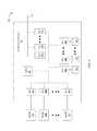
- FIG. 1is a schematic diagram showing a plurality of hosts and a data storage device that may be used in connection with the system described herein.
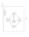
- FIG. 2is a schematic diagram showing a storage device, memory, a plurality of directors, and a communication module that may be used in connection with the system described herein.
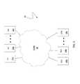
- FIG. 3is a schematic diagram showing a plurality of hosts coupled to a plurality of storage devices via a storage array network (SAN).
- SANstorage array network
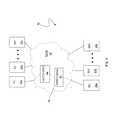
- FIG. 4is a schematic illustration of an embodiment of the SAN shown in FIG. 3 including multiple switches providing an I/O path between a host and a storage device in connection with an embodiment of the system described herein.
- FIG. 5is a schematic illustration of a tool, application and/or utility having a user interface that may receive as input path data identification information and workload characteristics of element of the path and output collected performance data metrics according to an embodiment of the system described herein.
- FIG. 6is a schematic illustration showing a changed I/O data path in the SAN that reflects a change from the I/O data path shown in FIG. 4 .
- FIG. 7is a schematic illustration showing an example of a controller of the interface for controlling path performance data collection according to an embodiment of the system described herein.
- FIG. 8is a schematic illustration showing another embodiment of a controller for controlling path performance data collection according to an embodiment of the system described herein.
- FIG. 9is a schematic illustration showing a controller that may be another screen of the interface according to an embodiment of the system described herein.
- FIG. 10is a schematic illustration of a path performance collection settings controller that may be a screen of the user interface according to an embodiment of the system described herein.
- FIG. 11is a schematic illustration showing a results display according to an embodiment of the system described herein.
- FIG. 12is a schematic illustration showing a groups controller that may be provided by the interface according to an embodiment of the system described herein.
- FIG. 13is a schematic illustration showing more specific information in a section concerning a group of hosts according to an embodiment of the system described herein.
- FIG. 14is a flow diagram showing an iteration of path discovery processing and path performance data collection processing according to an embodiment of the system described herein.
- FIG. 15is a more detailed flow diagram showing the processing of the system described herein for the automated identification of changes in I/O data paths and the collection of path performance data thereof according to an embodiment of the system described herein.
- FIG. 16is a schematic illustration showing a results display for an interface of an analytical tool according to an embodiment of the system described herein.
- FIG. 17is a schematic illustration showing, as a results display, display of a full data chart following selection by the user of a mini-chart of the display from FIG. 16 according to an embodiment of the system described herein.
- FIG. 18is a schematic illustration showing, as a results display, display of full data charts following selection by the user of an object of the display from FIG. 16 according to another embodiment of the system described herein.
- FIG. 19is a schematic illustration showing, as a results display, display of full data charts following customized selection by the user of elements of the display from FIG. 16 according to another embodiment of the system described herein.
- FIG. 20is a flow diagram showing performance data display processing using mini-charts according to an embodiment of the system described herein.
- FIG. 1is a schematic diagram 20 showing a plurality of hosts 22 a - 22 c coupled to a data storage device 24 that may be used in connection with an embodiment of the system described herein.
- the data storage device 24includes a memory 26 that facilitates operation of the storage device 24 , as further described elsewhere herein.
- the data storage devicealso includes a plurality of host adapters (HA's) 28 a - 28 c that handle reading and writing of data between the hosts 22 a - 22 c and the storage device 24 .
- HA'shost adapters
- the diagram 20shows each of the hosts 22 a - 22 c coupled to each of the HA's 28 a - 28 c , it will be appreciated by one of ordinary skill in the art that one or more of the HA's 28 a - 28 c may be coupled to other hosts.
- the storage device 24may be a Symmetrix storage device and/or a CLARiiON storage device produced by EMC Corporation of Hopkinton, Mass.
- the storage device 24may include one or more remote adapter units (RA's) 32 a - 32 c .
- An RAmay be used, for example, in connection with a remote data facility (RDF) product produced by EMC Corporation, may be used to copy data from one storage device to another. For example, if a host writes data to a first storage device (e.g., a local storage device), it may be desirable to copy that data to a second storage device provided in a different location (e.g., a remote storage device).
- RDFremote data facility
- the RA's 32 a - 32 care coupled to a remote link 40 and are similar to the HA's 28 a - 28 c , but are used to transfer data between the storage device 24 and other storage devices that are also coupled to the remote link 40 .
- the storage device 24may be coupled to additional RDF links (not shown) in addition to the remote link 40 .
- RDFand the use thereof in data recovery and storage techniques, see, for example, U.S. Pat. No. 5,742,792 to Yanai, et al., entitled “Remote Data Mirroring” and U.S. Pat. No. 7,779,291 to Yoder et al., entitled “Four Site Triangular Asynchronous Replication,” which are incorporated herein by reference.
- the storage device 24may also include one or more disks 36 a - 36 c , each containing a different portion of data stored on the storage device 24 .
- Each of the disks 36 a - 36 cmay be coupled to a corresponding one of a plurality of disk adapter units (DA) 38 a - 38 c that provides data to a corresponding one of the disks 36 a - 36 c and receives data from a corresponding one of the disks 36 a - 36 c .
- the disks 36 a - 36 cmay include any appropriate storage medium or mechanism, including hard disks, solid-state storage (flash memory), etc.
- datamay be appropriately understood, in various embodiments, to refer to data files, extents, blocks, chunks and/or other designations that indicate a unit, segment or collection of data.
- the logical storage space in the storage device 24 that corresponds to the disks 36 a - 36 cmay be subdivided into a plurality of volumes or logical devices.
- the logical devicesmay or may not correspond to the physical storage space of the disks 36 a - 36 c .
- the disk 36 amay contain a plurality of logical devices or, alternatively, a single logical device could span both of the disks 36 a , 36 b .
- the hosts 22 a - 22 cmay be configured to access any combination of logical devices independent of the location of the logical devices on the disks 36 a - 36 c .
- a device, such as a logical device described above,has a size or capacity that may be expressed in terms of device geometry.
- the device geometrymay include device geometry parameters regarding the number of cylinders in the device, the number of heads or tracks per cylinder, and the number of blocks per track, and these parameters may be used to identify locations on a disk. Other embodiments may use different
- One or more internal logical data path(s)exist between the DA's 38 a - 38 c , the HA's 28 a - 28 c , the RA's 32 a - 32 c , and the memory 26 .
- one or more internal buses and/or communication modulesmay be used.
- the memory 26may be used to facilitate data transferred between the DA's 38 a - 38 c , the HA's 28 a - 28 c and the RA's 32 a - 32 c .
- the memory 26may contain tasks that are to be performed by one or more of the DA's 38 a - 38 c , the HA's 28 a - 28 c and the RA's 32 a - 32 c and a cache for data fetched from one or more of the disks 36 a - 36 c . Use of the memory 26 is further described elsewhere herein in more detail.
- the storage device 24may be provided as a stand-alone device coupled to the hosts 22 a - 22 c as shown in FIG. 1 or, alternatively, the storage device 24 may be part of, and/or otherwise coupled to, a storage area network (SAN) that may include a plurality of other storage devices as well as switches, routers, network connections, etc., as further discussed elsewhere herein.
- SANstorage area network
- FIG. 2is a schematic diagram 50 illustrating an embodiment of the storage device 24 where each of a plurality of directors 52 a - 52 c are coupled to the memory 26 .
- Each of the directors 52 a - 52 cmay represent one of the HA's 28 a - 28 c , RA's 32 a - 32 c , and/or DA's 38 a - 38 c .
- the diagram 50also shows an optional communication module (CM) 54 that provides an alternative communication path between the directors 52 a - 52 c .
- CMcommunication module
- Each of the directors 52 a - 52 cmay be coupled to the CM 54 so that any one of the directors 52 a - 52 c may send a message and/or data to any other one of the directors 52 a - 52 c without needing to go through the memory 26 .
- the CM 54may be implemented using conventional MUX/router technology where a sending one of the directors 52 a - 52 c provides an appropriate address to cause a message and/or data to be received by an intended receiving one of the directors 52 a - 52 c .
- CM 54may be implemented using one or more of the directors 52 a - 52 c so that, for example, the directors 52 a - 52 c may be interconnected directly with the interconnection functionality being provided on each of the directors 52 a - 52 c .
- a sending one of the directors 52 a - 52 cmay be able to broadcast a message to all of the other directors 52 a - 52 c at the same time.
- one or more of the directors 52 a - 52 cmay have multiple processor systems thereon and thus may be able to perform functions for multiple directors. In some instances, at least one of the directors 52 a - 52 c having multiple processor systems thereon may simultaneously perform the functions of at least two different types of directors (e.g., an HA and a DA). Furthermore, in some embodiments, at least one of the directors 52 a - 52 c having multiple processor systems thereon may simultaneously perform the functions of at least one type of director and perform other processing with the other processing system.
- the memory 26may be a global memory in which all or at least part of the global memory may be provided on one or more of the directors 52 a - 52 c and shared with other ones of the directors 52 a - 52 c .
- the memory 26may be part of a global memory distributed across the processor systems of more than one storage device and accessible by each of the storage devices.
- a storage area networkmay be used to couple one or more host devices with one or more storage devices in a manner that allows reconfiguring connections without having to physically disconnect and reconnect cables from and to ports of the devices.
- a storage area networkmay be implemented using one or more switches to which the storage devices and the host devices are coupled. The switches may be programmed to allow connections between specific ports of devices coupled to the switches. A port that can initiate a data-path connection may be called an “initiator” port while the other port may be deemed a “target” port.
- FIG. 3is a schematic illustration 80 showing a storage area network (SAN) 60 providing a SAN fabric coupling a plurality of host devices (H1-HN) 22 a - c to a plurality of storage devices (SD1-SDN) 24 a - c .
- Each of the devices 22 a - c , 24 a - cmay have a corresponding port that is physically coupled to switches of the SAN fabric used to implement the storage area network 60 .
- the switchesmay be separately programmed by one of the devices 22 a - c , 24 a - c or by a different device (not shown).
- Programming the switchesmay include setting up specific zones that describe allowable data-path connections (which ports may form a data-path connection) and possible allowable initiator ports of those configurations. For example, there may be a zone for connecting the port of the host 22 a with the port of the storage device 24 a . Upon becoming activated (e.g., powering up), the host 22 a and the storage device 24 a may send appropriate signals to the switch(es) of the storage area network 60 , and each other, which then allows the host 22 a to initiate a data-path connection between the port of the host 22 a and the port of the storage device 24 a . Zones may be defined in terms of a unique identifier associated with each of the ports, such as such as a 64-bit world-wide port name (WWPN).
- WWPNworld-wide port name
- the system described hereinmay be used in connection with performance data collection for data migration and/or data mirroring techniques using a SAN.
- Data transfer among storage devicesmay involve various data synchronization processing and techniques to provide reliable protection copies of data among a source site and a destination site.
- synchronous transfersdata may be transmitted to a remote site and an acknowledgement of a successful write is transmitted synchronously with the completion thereof.
- a data transfer processmay be initiated and a data write may be acknowledged before the data is actually transferred to directors at the remote site.
- Asynchronous transfersmay occur in connection with sites located geographically distant from each other. Asynchronous distances may be distances in which asynchronous transfers are used because synchronous transfers would take more time than is preferable or desired. Examples of data migration and mirroring products includes Symmetrix Remote Data Facility (SRDF) products from EMC Corporation.
- SRDFSymmetrix Remote Data Facility
- FIG. 4is a schematic illustration 82 showing multiple SAN switches of a SAN, like that of FIG. 3 , that may be used in connection with an embodiment of the system described herein.
- the SANis shown with two switches, switch 61 (SW1) and switch 62 (SW2), that are used in connection with an I/O data path 70 from the host 22 a to the storage device 24 a .
- the switches 61 , 62may include physical and/or logical devices.
- switchesare shown, more than two switches and/or other appropriate elements of a SAN fabric may be used in connection with the providing of I/O data paths from one or more of the hosts 22 a - c to one or more of the storages devices 24 a - c in connection with path performance data collection according to the system described herein.
- the selection and/or identification of the I/O path 70may be performed according to multiple selection factors and using known path selection techniques.
- FIG. 5is a schematic illustration of an tool, application and/or utility 100 , having a user interface 110 , that may receive as input path data identification information and performance indicators for workload characteristics of elements of the path and output collected performance data metrics according to an embodiment of the system described herein.
- Workload characteristicsmay include for each configuration item (CI) of the I/O path from a host to a storage device, through a SAN, such as the average number of I/Os per unit time (e.g., seconds), the write percentage and/or the average amount of data per unit time (e.g., number of MB per second), among other appropriate characteristics and performance indicators.
- the user interface 110 of the tool 100may allow configuration by a user in connection with turning on and off data collection for multiple I/O paths, as further discussed elsewhere herein.
- the user interface 110 of the tool 100 according to the system describedmay then display and/or otherwise output path data performance measures and statistics.
- the tool 100may be an application installed on an application host or other computer providing SAN administration and/or management functionality and/or may be installed on one or more of the hosts 22 a - c coupled to the SAN.
- the tool 100may include a ProSphere® product produced by EMC Corporation that provides storage resource management functionality. It is noted that statistics used by the tool 100 according to the system described herein may be gathered by the tool itself and/or may be obtained from other sources, such as, for example, data obtained from products produced by EMC Corporation including, the EMC Workload Analyzer (WLA), the Symmetrix Performance Analyzer (SPA)® and/or the Symmetrix CLI statistics collection daemon (STP), among other possible collection devices, applications and/or tools.
- WLAEMC Workload Analyzer
- SPASymmetrix Performance Analyzer
- STPSymmetrix CLI statistics collection daemon
- the tool 100provides for controlled tuning performance data collection through a single application control.
- performance data collectionmay be turned on or off from the application host running the tool 100 via the user interface 110 .
- the tool 100may automatically (e.g., without user intervention) update performance data collection characteristics as the application host I/O data path changes according to user controlled settings but without requiring further user intervention during the updating.
- the toolmay update continuously and/or at specified intervals.
- Turning on path performance data collection on the application host via the user interface 110may automatically set up synchronized performance data collection for all managed objects within an I/O data path.
- a data I/O pathmay be made up of managed objects from the application host, such as host 22 a , though multiple switches 61 , 62 in the SAN fabric 60 down to the storage device 24 a to which the application host (host 22 a ) is connected (see FIG. 4 ).
- the system described hereinmay automatically determine what has changed for any I/O data path for the application host and adjust what performance data is to be collected and may ensure collection continues to be synchronized.
- Such functionalitymay advantageously be used for troubleshooting performance issues for an application from an end-to-end perspective.
- FIG. 6is a schematic illustration 84 showing a changed I/O data path 72 in the SAN 60 that reflects a change from the I/O data path 70 shown in FIG. 4 .
- a change in the I/O data path of the host 22 ais shown schematically in which the I/O data path 72 now includes switch 61 (SW1) and switch 63 (SW3), instead of switch 62 (SW2), and a storage device has been swapped such that I/O data path of the host 22 a is now includes the storage device 24 b (SD2) rather than storage device 24 a (SD1).
- the changes to the I/O pathmay include, for example, changes to host devices, switches, switch ports, storage devices and/or device ports, among other suitable I/O data path element changes.
- the tool 100may automatically determine the changes in the I/O data path 72 and adjust the data performance metrics being collected according to the new elements of the I/O data path 72 without requiring any user intervention.
- FIG. 7is a schematic illustration showing an example of a controller 200 of the interface 110 according to an embodiment of the system described herein.
- the controller 200may be a screen of the interface 110 and provides data path discovery and performance data collection control functionality in connection with the tool 100 .
- Multiple elements of I/O data pathssuch as the I/O data path 70 or the I/O data path 72 , may be discovered according to the system described herein in accordance with techniques discussed elsewhere herein.
- the elements, shown in header section 210may include discovered hosts, switches, fabrics, arrays, and groups/clusters.
- the particular header of section 210 shown in the figurecorresponds to discovered hosts 212 which may provide an indication of the discovery of complete I/O data paths from one or more hosts through the SAN and elements thereof to one or more storage devices or arrays.
- section 220details multiple I/O data paths that have been discovered for multiple hosts.
- Information of the I/O data pathsidentifies the discovered hosts, whether the hosts are virtual (e.g., running as guest operating system or a virtual machine (VM)) or not, the hosts' IP addresses, operating systems and versions thereof, and whether the host is in a group or cluster.
- column 222identifies whether data path performance collection has been activated and column 224 identifies when the last successful discovery process performed to identify the hosts and I/O data paths.
- the discovery processmay be performed automatically, for example, at periodic scheduled intervals.
- a usermay also use the interface 110 to manually provide for a discovery process in addition to scheduled discovery processes, for example, by activating the Discover button 231 in the section 230 further discussed below.
- Section 230provides for control by a user using the interface 110 of the discovery and path performance data collection processes.
- the Discover button 231may be used by a user to manual activate a I/O data path discovery process; however, the system described herein may further operate with automatic discovery scans.
- the interfaceprovides for a single-click control interface to turn on or off path data collection processing for particular I/O data path(s). This is illustrated with the Turn On Collection button 232 and the Turn Off Collection button 233 that may be used for any one or more of the I/O data paths for the discovered hosts shown in the section 220 .
- the system described hereinalso provides for grouping host I/O data paths to allow for consolidated analysis of the I/O data paths with a single click using the interface 110 .
- Thisis illustrated by the Add to Groups button 234 , as further discussed elsewhere herein. It is noted that other layouts and configurations for the controller 200 , like that of other interface controller screens discussed elsewhere herein, are possible and may be configured according to particular administrator and system policies and requirements.
- FIG. 8is a schematic illustration showing a controller 200 ′, like the controller 200 , in which, for a host entry 240 for host “losbc62”, path performance data collection has been turned on, as shown by the indicator 242 , according to an embodiment of the system described herein.
- path performance data collectionmay be turned on by selecting the desired host and clicking on the Turn ON Collection button 232 and/or, alternatively, the indicator 242 may provide for a toggling action between ON and OFF by clicking directly on the indicator 242 .
- path performance collectionmay occur for every I/O data path of the host 240 , thereby the collection may be synchronized for all elements of the I/O data paths to collect statistics for the elements at the same time.
- Settings for path performance collectionmay be controlled by a default settings.
- the intervals between collection scansmay be subject to a default setting.
- the intervalmay be 5 minutes, but may be set to any desirable interval.
- Settings for a specific hostmay be controlled via the interface 110 by clicking on a Settings link or button 244 for each discovered host for which path performance collection is activated that will allow the user to view and adjust settings from a settings controller, as further discussed elsewhere herein.
- results of the data collection for I/O data paths of the hostmay be viewed by clicking on a Results button 235 , as further discussed elsewhere herein.
- FIG. 9is a schematic illustration showing a controller 300 that may be another screen of the interface 110 according to an embodiment of the system described herein.
- the controller 300shows identification of discovered arrays/storage devices of a SAN, similar to the display of discovered hosts shown in connection with interface screens of the controllers 200 , 200 ′. It is noted that screens similar to that described for the controller 300 may be provided for other discovered elements including discovered switches and fabrics of the SAN, as illustrated by the tabs in section 310 .
- Section 320shows discovered arrays that have been discovered by one or more discovery scans.
- the discovery processmay be performed automatically, for example, at periodic scheduled intervals.
- a usermay also use the interface 110 to manually provide for a discovery process in addition to scheduled discovery processes, for example, by activating the Discover button 331 in section 330 further discussed below.
- the section 320provides various information concerning discovered arrays including name, vendor, model, microcode and time of last update. Additionally, column 324 shows the Discovery state or status of the arrays. For example, a successful discovery may indicate that a particular array has been identified and all relevant information for inclusion in an I/O data path identified, whereas a failed discovery may indicate that certain information from the particular array has not been determined by the last discovery scan. The system may attempt to resolve failures with periodic scans. A status of “Running” may indicate that the array is in an I/O data path for which performance data is currently being collected. Column 322 shows whether path performance collection has been turned on or off for the array.
- the path performance collection indicator 342shows that path performance collection is turned on for the array, thereby the array is in an I/O data path for which performance data is being collected.
- the array 340may be in one or more of the I/O data paths for the host losbc62 (see FIGS. 7 and 8 ) for which collection of path performance data has been turned on.
- a settings link/button 344may be used to identify the settings and other collection information, such as identification of the I/O data path, for the array 340 , as further discussed elsewhere herein. Buttons 332 and 333 of the section 330 may be used to turn performance data collection on or off for a particular array. This level of control may enable problem identification in particular elements (arrays, switches, fabric etc.) of an I/O data path.
- a results button 335may be used to view displayed results of the performance data collection, as further discussed elsewhere herein.
- FIG. 10is a schematic illustration of a path performance collection settings controller 400 that may be a screen of the user interface 110 according to an embodiment of the system described herein.
- Section 410shows the schedule for the automated “smart” collection of performance data for all I/O data paths for host losbc62.
- Section 420enables selection and viewing of collection setting information for particular elements of the I/O data paths of the indicated host, including but not limited to workload and performance characteristics such as CPU utilization, memory utilization for the host and IOps (I/O in Mb per sec), response time in ms, throughput in Kbps, and queue length for host devices. Other elements for which information may be obtained include the switches and arrays, as shown in section 420 .
- Section 430shows buttons that allow the user to edit settings of the path performance data collection, among other control functionalities.
- FIG. 11is a schematic illustration showing a results display 500 , for example, after clicking on the results button 235 according to an embodiment of the system described herein.
- the results display 500may include a graphical section 510 that shows a visual representation of an I/O data path for the selected host, in the illustrated case, for host losbc62.
- the section 510graphical displays the host 512 , coupled via SAN switches 514 , to one or more storage devices/arrays 516 .
- Section 520may display map details of the I/O data paths, for example performance data for particular elements of the I/O data paths in graph form 522 , 524 , 526 as well as in text or tabulated form 528 .
- the performance measures displayedmay include those discussed elsewhere herein, including workload and performance characteristics such as CPU utilization, memory utilization for the host and IOps (I/O in Mb per sec), response time in ms, throughput in KBps, and queue length for host devices, switches, arrays etc., among other appropriate measures.
- Section 530indicates that multiple types of detail and performance measures may be displayed in various forms for the application host, including features corresponding to the I/O data path attributes, performance, capacity, alerts, connectivity, path details, virtual machine (VM) information, data stores, configuration changes, discovery details and group details.
- a link button 532may be provided to view performance collection settings.
- portion 534indicates that historical or past performance data collection may be maintained by the system. For example, a user may view past performance data collection from the prior day, prior week, prior month and/or any other customizable date range.
- FIG. 12is a schematic illustration showing a groups controller 600 that may be provided by the interface 110 according to an embodiment of the system described herein.
- the group controller 600enables the selection, creation and configuring of groups of elements in I/O data paths according to the system described herein. Groups may be defined using default settings for the entire group (e.g., Groups) and/or may be configurable with specific collection settings within a group (e.g., Smart Groups). Section 610 shows the identification of various group types and subsets thereof. Section 620 shows specific information concerning selected groups and may include information for groups of hosts, arrays, fabrics, switches etc. of the I/O data paths. Column 622 shows the indicators for whether path performance collection is turned on or off for particular groups.
- an indicator 642shows that path performance collection is turned on for a group of hosts 640 .
- Section 630shows buttons that may be used to create and delete groups and smart groups according to configurations by the user. Information concerning groups may also be shared and unshared and imported and exported, as shown by buttons in the section 630 . It is noted that group settings may be created and/or shared among groups of varying geographical regions (e.g., Boston, Saint Louis, New York etc.).
- FIG. 13is a schematic illustration showing more specific information in a section 620 ′ concerning a group of hosts 650 according to an embodiment of the system described herein.
- Hosts 1-12 650are shown in the illustrated screen window and it is noted that the turning of path performance collection on for the entire group in FIG. 12 has turned on path performance collection for the I/O data paths of each of the Hosts 1-12 650 as shown by the indicators 652 in accordance with the system described herein.
- Section 630 ′shows Turn ON Collection and Turn OFF Collection buttons that may be used to turn on or off collections for individual ones of the selected host group. Other configurations and groups designations may be specified by a user according to desired administrator and/or system requirements.
- FIG. 14is a flow diagram 700 showing an iteration of path discovery processing and path performance data collection processing according to an embodiment of the system described herein.
- a discovery processis performed to identify elements of a SAN through which one or more I/O data paths of one or more host exist. I/O data paths may exist from one or more hosts to one or more storage arrays or devices via switches and/or other elements of the SAN.
- the discovery processmay be automated to occur continuously and/or at scheduled intervals. Accordingly, the process may automatically identify changes to I/O data paths that may occur as a result of changes to the elements of the SAN without requiring user intervention.
- Settings controlling the automationmay be set and/or otherwise controlled via a user interface, as further discussed elsewhere herein.
- processingproceeds to a step 704 where the discovered elements from the discovery process may be displayed on the user interface.
- the discovered elementsmay include one or more hosts from which one or more I/O data paths extend.
- processingproceeds to a step 706 where the interface receives user input to turn on performance data collection for the one or more of the discovered hosts to collect performance data for the I/O data paths thereof.
- the inputis a single click on a performance data collection indicator and/or an button to turn on collection.
- processingproceeds to a step 708 where performance data for I/O data paths of the one or more selected hosts is collected.
- processingproceeds to a test step 710 where it is determined whether the results of the collection are to be displayed. For example, whether the user has requested the interface to display the results. If not then processing of the iteration of performance data collection is complete. If the results are to be displayed, then processing proceeds to a step 712 where the collection results are displayed on the interface. After the step 712 , processing of the iteration is complete.
- FIG. 15is a more detailed flow diagram 800 showing the processing of the system described herein for the automated identification of changes in I/O data paths and the collection of path performance data thereof according to an embodiment of the system described herein.
- an path performance data collection applicationaccording to the system described herein is executed.
- processingproceeds to a step 804 where discovery processing is performed to discover elements of one or more storage area networks, including hosts and storage arrays, according to the system described herein.
- processingproceeds to a test step 806 where it is determined whether path performance collection processing has been activated for one or more of the discovered hosts.
- path performance collection processingmay be activated, for example, via an interface by an user clicking, with a single click, on a path performance collection button or indicator.
- processingproceeds to a test step 808 where it is determined whether another discovery scan is to occur according to the scheduled intervals for discovery scans for automatically updating the discovery processes according to the system described herein. Discovery scans may be scheduled through the interface. If it is time for a scheduled discovery scan, then processing proceeds back to the step 804 . Otherwise, processing proceeds from the test step 808 to a test step 810 where it is determined whether any performance data collection processing has been activated by a user. If not then processing proceeds back to the test step 808 . In this way, the system described herein provides for automated and continuous discovery scanning while a path performance data collection application is active.
- processingproceeds to a step 812 where path performance data is collected for all I/O paths of one or more discovered hosts according or other objects to the selections made via the interface.
- processingproceeds to a test step 814 where it is determined whether path performance data collection is to continue. For example, it is determined whether a user has turned off collection for the selected hosts via the interface. If path performance data collection is not to continue as determined at the test step 814 (e.g. the user has clicked on the turn off collection button/indicator) then processing proceeds back to the test step 808 where it is again determined whether another scheduled discovery scan is to occur to update the discovered elements, as discussed above.
- processingproceeds to a test step 816 where it is determined whether another scheduled discovery scan is to occur. If not then processing proceeds back to the step 812 where the system continues to collect path performance data for the I/O data path(s) of the selected host(s). If, at the test step 816 , it is determined that it is time for another scheduled discovery scan, then processing proceeds to a step 818 where the discovery scan is performed. After the step 818 , processing proceeds to a test step 820 where it is determined whether any of the I/O data paths of the selected host(s) have changed.
- processingproceeds back to the step 812 where the system continues to collect path performance data for the current I/O data path(s) of the selected host(s). If, however, at the test step 820 , it is determined that one or more of the I/O data paths have changed, then processing proceeds to a step 822 where the I/O data path information is updated automatically by the system described herein and path performance data for the changed I/O data paths is collected. After the step 822 , processing proceeds back to the test step 814 where it is determined whether path performance data collection is to continue. Accordingly, the system described herein provides a self-tuning path performance data collection system using a single application control interface that may automatically and continuously update host I/O data path changes without requiring user intervention to detect and process the changes.
- Suitable data storage system simulation toolsthat may be used in connection with the system described herein may include systems and methods like that disclosed in U.S. Pat. No. 7,392,360 to Aharoni et al., entitled “Method and System for Capacity Planning and Configuring One or More Data Storage Systems,” U.S. Pat. No. 7,292,969 to Aharoni et al., entitled “Method and System for Simulating Performance on One or More Storage Systems,” and U.S. patent application Ser. No. 13/065,806 to Smirnov et al., filed Mar. 30, 2011, entitled “Write Pacing Simulation Tool,” which are all assigned to EMC Corporation and which are all incorporated herein by reference.
- the system described hereinmay provide display results from performance data analyses that present mini-chart overlays on a topology map based on intelligent analytics for components in one or more I/O data paths.
- the mini-chartsmay be advantageously used to show criticality of impact to assist a user with incident avoidance and/or to provide fast incident resolution.
- the usermay enable mini-charts and visually see from the charts where a possible performance bottleneck is detected by the analytics.
- the mini-charts for the most relevant metricsmay be displayed and identified for criticality.
- the mini-chartsmay be colored and/or sized for criticality, among other appropriate visual criticality designations.
- the criticality visualsmay be determined by thresholds, that may be set by a user and/or determined by the system, and may be calculated automatically based on learned base line, maximum line and minimum line operations over set times. A user may manually override a threshold set by the system, if desired.
- the mini-chartsmay represent a small image of a full data chart. By selecting a mini-chart, the user may be shown the larger chart version and/or other details that may enable the user to locate and identify specific performance issues.
- An I/O data pathmay be made up of managed objects from an application host through multiple storage switches in the storage fabric down to the storage arrays to which the application host is connected. Performance metrics may be collected and analyzed by the system for selected objects, as discussed elsewhere herein. Events and alerts may be generated that alert the user to one or more conditions. The user may then select a relevant object and see the high level performance map based on the topology, as aided by the mini-charts and analytics described herein.
- the system described hereinadvantageously simplifies the troubleshooting of performance issues for an application from an end-to-end perspective.
- the system described hereinreduces required steps for display of useful performance analytics for a user.
- the usermay simply turn on mini-charts (e.g., with a single click of a button) on the topology map of a selected application host or other object and the system described herein will handle correlation, chart creation, and analytical evaluation of potential bottlenecks and their visualization without requiring further user intervention.
- the systemmay advantageously calculate thresholds and base lines based on learned or determined analytics and highlight mini-charts, for example, in colors such as red, green, yellow or other appropriate colors of a color coded criticality schema, to draw attention to main problem areas.
- an alternative I/O path between relevant objectsmay be determined and selected either manually by a user and/or, in some cases, automatically by the system according to one or more policies.
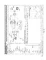
- FIG. 16is a schematic illustration showing a results display 900 for an interface of an analytical tool, like the interface 110 and tool 100 discussed elsewhere herein, according to an embodiment of the system described herein.
- multiple tabsare shown in connection with obtaining performance data results for particular objects, including hosts, switches and arrays of an I/O path to or from a particular element (e.g., shown for objects and elements identified as: losbc081, UCbrocade, and Array 1).
- the results shown in the display 900are for evaluations of an I/O path determined in connection with Array 1.
- a topology map 910is shown for objects in the I/O path from the application host (losbc081) through switches of a fabric down to the Array 1.
- the objects and elements shown in the I/O pathmay be filtered using controls 920 that, for example, enable filtering of a topology map according to various categories of objects and elements, including hosts, switches or other elements of a network fabric and storage arrays.
- Other controls 901 of the display 900may be provided, including a launch element manager control that may enable a user to launch to an interface and/or another application to manage a particular problem object identified according to the system described herein and/or a group button to add one or more objects to a particular group, among other control options.
- a control button 905is shown that may provide for enabling or disabling the display of the min-charts on the topology map. As illustrated, mini-charts have been enabled and multiple mini-charts 911 - 916 are shown on the topology map 910 and visually presented adjacent to corresponding objects and elements of the I/O path (e.g., the control button 905 has been clicked and mini-charts have been enabled).
- the mini-chartsmay be representative of full data charts corresponding to the collected performance data for the objects and elements of the I/O path. In an embodiment, the mini-chart may be a smaller version of the full data chart that visually resembles the full data chart, but which contains less presented data than the full data chart.
- the mini-charts 911 - 916may be visually presented corresponding to thresholds of related data and indicate alerts levels of problem areas in the I/O path.
- the mini-charts 911 - 916may be colored for criticality according to a color coded criticality schema.
- the multiple color aspect of the mini-chartsis illustrated in the figure by different styles of dashed-line borders of the mini-charts 911 - 916 .
- a details display segment 930is shown that may provide performance information and other detailed information, including, for example, information of attributes, connectivity, path details, VMs, data stores, clusters, alerts, breaches and used defined groups (UDG) in connection with the I/O path shown in the topology map 910 .
- UDGused defined groups
- FIG. 17is a schematic illustration showing, as a results display 900 a , display of a full data chart following selection by the user of a mini-chart of the display 900 from FIG. 16 according to an embodiment of the system described herein.
- the illustrated display 900 ashows a details display segment 930 a after a user clicks on or otherwise selects the mini-chart 911 shown for the Array 1 object.
- the details display segment 930 adisplays, under performance details, the full data chart 931 corresponding to the mini-chart 911 .
- chart 931shows array port link utilization of the Array 1.
- FIG. 18is a schematic illustration showing, as a results display 900 b , display of full data charts following selection by the user of an object of the display 900 from FIG. 16 according to another embodiment of the system described herein.
- the illustrated display 900 bshows a details display segment 930 b after a user clicks on or otherwise selects the application host losbc081, which may display all charts corresponding to available mini-charts (e.g., the mini-charts 915 and 916 ) for the host losbc081.
- the details display segment 930 adisplays, under performance details, the full data charts 932 and 933 corresponding to the mini-charts 915 and 916 for losbc081.
- the chart 932shows host port link utilization for losbc081
- the chart 933shows host memory and CPU utilization for losbc081.
- FIG. 19is a schematic illustration showing, as a results display 900 c , display of full data charts following customized selection by the user of elements of the display 900 from FIG. 16 according to another embodiment of the system described herein.
- the illustrated display 900 cshows a details display segment 930 c after a user clicks on or otherwise selects mini-charts 911 , 915 and 916 .
- the details display segment 930 cdisplays, under performance details, the full data charts 931 , 932 and 933 corresponding to the mini-charts 911 , 915 and 916 for Array 1 and losbc081.
- the chart 931shows array port link utilization of the Array 1
- the chart 932shows host port link utilization for losbc081
- the chart 933shows host memory and CPU utilization for losbc081. It is noted that any desired selection of mini-charts is possible, and the system described herein thereby enables advantageous customization for a user to select and display one or more of any desired mini-charts to aid in problem resolution for I/O paths in the network topology.
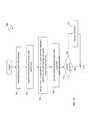
- FIG. 20is a flow diagram 1000 showing performance data display processing using mini-charts according to an embodiment of the system described herein.
- a topology mapis generated according to discovery processing performed by the system described herein and based on user configurations and displayed on a results display like that further discussed elsewhere herein.
- processingproceeds to a test step 1004 where it is determined whether display of mini-charts has been activated, for example, by action of a user. If, at the test step 1004 , it is determined that no mini-charts are to be displayed, then processing proceeds to a step 1006 where other performance data display processing, other than that using mini-charts, is provided. After the step 1006 , processing proceeds back to the test step 1004 .
- mini-chartsare determined according to the collected performance data, and determined analytics thereof, for relevant objects of an I/O path.
- the mini-chartsmay be representative of full data charts corresponding to collected performance data for the relevant objects of the I/O path, and may be colored and/or otherwise designated according to criticality thresholds. For example, a threshold may be determined corresponding to port link utilization, that, if reached, causes the mini-chart to appear red, or be otherwise colored or displayed, to indicate a potential problem.
- the thresholdmay be set dynamically over time by automatic action of the system described herein based on the analytics determined for the collected performance data. Specifically, one or more thresholds may be set according to determinations of base line system operations, minimum line system operations and maximum line system operations over a particular period of time. After the step 1008 , processing proceeds to a step 1010 where the mini-charts are displayed on the topology map.
- processingproceeds to a test step 1012 where it is determined whether one or more of the mini-charts have been selected by the user. If not, then processing proceeds back to the step 1008 in may what may be part of refresh processing in which the mini-charts are periodically updated. If, at the test step 1012 , it is determined that the user has selected one or more of the mini-charts (for example, by a single click of a user on a mini-chart enable button), then processing proceeds to a step 1014 where full data charts corresponding to the selected mini-charts are displayed on the results display. After the step 1014 , processing proceeds back to the step 1008 according to the above-noted refresh processing.
- the computer readable mediummay include a computer hard drive, ROM, RAM, flash memory, portable computer storage media such as a CD-ROM, a DVD-ROM, a flash drive and/or other drive with, for example, a universal serial bus (USB) interface, and/or any other appropriate tangible or non-transitory computer readable medium or computer memory on which executable code may be stored and executed by a processor.
- a computer hard driveROM
- RAMrandom access memory
- portable computer storage mediasuch as a CD-ROM, a DVD-ROM, a flash drive and/or other drive with, for example, a universal serial bus (USB) interface, and/or any other appropriate tangible or non-transitory computer readable medium or computer memory on which executable code may be stored and executed by a processor.
- USBuniversal serial bus
Landscapes
- Engineering & Computer Science (AREA)
- Computer Networks & Wireless Communication (AREA)
- Signal Processing (AREA)
- Computer Graphics (AREA)
- Physics & Mathematics (AREA)
- General Physics & Mathematics (AREA)
- Theoretical Computer Science (AREA)
- Debugging And Monitoring (AREA)
Abstract
Description
Claims (20)
Priority Applications (1)
| Application Number | Priority Date | Filing Date | Title |
|---|---|---|---|
| US13/629,805US9202304B1 (en) | 2012-09-28 | 2012-09-28 | Path performance mini-charts |
Applications Claiming Priority (1)
| Application Number | Priority Date | Filing Date | Title |
|---|---|---|---|
| US13/629,805US9202304B1 (en) | 2012-09-28 | 2012-09-28 | Path performance mini-charts |
Publications (1)
| Publication Number | Publication Date |
|---|---|
| US9202304B1true US9202304B1 (en) | 2015-12-01 |
Family
ID=54609293
Family Applications (1)
| Application Number | Title | Priority Date | Filing Date |
|---|---|---|---|
| US13/629,805Active2033-02-20US9202304B1 (en) | 2012-09-28 | 2012-09-28 | Path performance mini-charts |
Country Status (1)
| Country | Link |
|---|---|
| US (1) | US9202304B1 (en) |
Cited By (18)
| Publication number | Priority date | Publication date | Assignee | Title |
|---|---|---|---|---|
| US20140371883A1 (en)* | 2013-06-13 | 2014-12-18 | Dell Products L.P. | System and method for switch management |
| US20160259558A1 (en)* | 2014-04-03 | 2016-09-08 | Hitachi, Ltd. | Management system and management method for computer system comprising remote copy system for performing asynchronous remote copy |
| US20160323804A1 (en)* | 2014-01-09 | 2016-11-03 | Nec Corporation | Node device |
| US20170187581A1 (en)* | 2015-12-28 | 2017-06-29 | Silver Peak Systems, Inc. | Dynamic Monitoring and Visualization for Network Health Characteristics |
| US9875344B1 (en) | 2014-09-05 | 2018-01-23 | Silver Peak Systems, Inc. | Dynamic monitoring and authorization of an optimization device |
| US9906630B2 (en) | 2011-10-14 | 2018-02-27 | Silver Peak Systems, Inc. | Processing data packets in performance enhancing proxy (PEP) environment |
| US9948496B1 (en) | 2014-07-30 | 2018-04-17 | Silver Peak Systems, Inc. | Determining a transit appliance for data traffic to a software service |
| US9961010B2 (en) | 2006-08-02 | 2018-05-01 | Silver Peak Systems, Inc. | Communications scheduler |
| US9967056B1 (en) | 2016-08-19 | 2018-05-08 | Silver Peak Systems, Inc. | Forward packet recovery with constrained overhead |
| US10257082B2 (en) | 2017-02-06 | 2019-04-09 | Silver Peak Systems, Inc. | Multi-level learning for classifying traffic flows |
| US10313930B2 (en) | 2008-07-03 | 2019-06-04 | Silver Peak Systems, Inc. | Virtual wide area network overlays |
| US10432484B2 (en) | 2016-06-13 | 2019-10-01 | Silver Peak Systems, Inc. | Aggregating select network traffic statistics |
| US10637721B2 (en) | 2018-03-12 | 2020-04-28 | Silver Peak Systems, Inc. | Detecting path break conditions while minimizing network overhead |
| US10771394B2 (en) | 2017-02-06 | 2020-09-08 | Silver Peak Systems, Inc. | Multi-level learning for classifying traffic flows on a first packet from DNS data |
| US10805840B2 (en) | 2008-07-03 | 2020-10-13 | Silver Peak Systems, Inc. | Data transmission via a virtual wide area network overlay |
| US10892978B2 (en) | 2017-02-06 | 2021-01-12 | Silver Peak Systems, Inc. | Multi-level learning for classifying traffic flows from first packet data |
| US11044202B2 (en) | 2017-02-06 | 2021-06-22 | Silver Peak Systems, Inc. | Multi-level learning for predicting and classifying traffic flows from first packet data |
| US11212210B2 (en) | 2017-09-21 | 2021-12-28 | Silver Peak Systems, Inc. | Selective route exporting using source type |
Citations (24)
| Publication number | Priority date | Publication date | Assignee | Title |
|---|---|---|---|---|
| US5206939A (en) | 1990-09-24 | 1993-04-27 | Emc Corporation | System and method for disk mapping and data retrieval |
| US5226120A (en)* | 1990-05-21 | 1993-07-06 | Synoptics Communications, Inc. | Apparatus and method of monitoring the status of a local area network |
| US5742792A (en) | 1993-04-23 | 1998-04-21 | Emc Corporation | Remote data mirroring |
| US5778394A (en) | 1996-12-23 | 1998-07-07 | Emc Corporation | Space reclamation system and method for use in connection with tape logging system |
| US5845147A (en) | 1996-03-19 | 1998-12-01 | Emc Corporation | Single lock command for an I/O storage system that performs both locking and I/O data operation |
| US5857208A (en) | 1996-05-31 | 1999-01-05 | Emc Corporation | Method and apparatus for performing point in time backup operation in a computer system |
| US6144379A (en)* | 1997-11-20 | 2000-11-07 | International Business Machines Corporation | Computer controlled user interactive display system for presenting graphs with interactive icons for accessing related graphs |
| US6434637B1 (en) | 1998-12-31 | 2002-08-13 | Emc Corporation | Method and apparatus for balancing workloads among paths in a multi-path computer system based on the state of previous I/O operations |
| US6622221B1 (en) | 2000-08-17 | 2003-09-16 | Emc Corporation | Workload analyzer and optimizer integration |
| US20050108643A1 (en)* | 2003-11-17 | 2005-05-19 | Nokia Corporation | Topographic presentation of media files in a media diary application |
| US20070067296A1 (en)* | 2005-08-19 | 2007-03-22 | Malloy Patrick J | Network capacity planning |
| US7292969B1 (en) | 2002-09-27 | 2007-11-06 | Emc Corporation | Method and system for simulating performance on one or more data storage systems |
| US20080115049A1 (en)* | 2006-11-14 | 2008-05-15 | Microsoft Corporation | Dynamically generating mini-graphs to represent style and template icons |
| US7392360B1 (en) | 2002-09-27 | 2008-06-24 | Emc Corporation | Method and system for capacity planning and configuring one or more data storage systems |
| US7441023B2 (en) | 2003-09-25 | 2008-10-21 | Emc Corporation | Method and apparatus for modeling and analyzing MPLS and virtual private networks |
| US20090282325A1 (en)* | 2008-05-07 | 2009-11-12 | Microsoft Corporation | Sparklines in the grid |
| US7688753B1 (en) | 2007-12-28 | 2010-03-30 | Emc Corporation | Selection of a data path based on one or more performance characteristics of a computer system |
| US7720003B2 (en) | 2003-09-25 | 2010-05-18 | Emc Corporation | Model-based method and apparatus for determining MPLS network properties |
| US7779291B2 (en) | 2006-12-29 | 2010-08-17 | Emc Corporation | Four site triangular asynchronous replication |
| US8028062B1 (en) | 2007-12-26 | 2011-09-27 | Emc Corporation | Non-disruptive data mobility using virtual storage area networks with split-path virtualization |
| US20120110460A1 (en)* | 2010-10-27 | 2012-05-03 | Russell David Wilson | Methods and Systems for Monitoring Network Performance |
| US20130019197A1 (en)* | 2011-07-11 | 2013-01-17 | International Business Machines Corporation | Displaying computer dashboard information |
| US8364460B2 (en)* | 2008-02-13 | 2013-01-29 | Quest Software, Inc. | Systems and methods for analyzing performance of virtual environments |
| US20140019899A1 (en)* | 2012-07-16 | 2014-01-16 | Microsoft Corporation | Location-Dependent Drag and Drop UI |
- 2012
- 2012-09-28USUS13/629,805patent/US9202304B1/enactiveActive
Patent Citations (26)
| Publication number | Priority date | Publication date | Assignee | Title |
|---|---|---|---|---|
| US5226120A (en)* | 1990-05-21 | 1993-07-06 | Synoptics Communications, Inc. | Apparatus and method of monitoring the status of a local area network |
| US5206939A (en) | 1990-09-24 | 1993-04-27 | Emc Corporation | System and method for disk mapping and data retrieval |
| US5742792A (en) | 1993-04-23 | 1998-04-21 | Emc Corporation | Remote data mirroring |
| US5845147A (en) | 1996-03-19 | 1998-12-01 | Emc Corporation | Single lock command for an I/O storage system that performs both locking and I/O data operation |
| US5857208A (en) | 1996-05-31 | 1999-01-05 | Emc Corporation | Method and apparatus for performing point in time backup operation in a computer system |
| US5778394A (en) | 1996-12-23 | 1998-07-07 | Emc Corporation | Space reclamation system and method for use in connection with tape logging system |
| US6144379A (en)* | 1997-11-20 | 2000-11-07 | International Business Machines Corporation | Computer controlled user interactive display system for presenting graphs with interactive icons for accessing related graphs |
| US6434637B1 (en) | 1998-12-31 | 2002-08-13 | Emc Corporation | Method and apparatus for balancing workloads among paths in a multi-path computer system based on the state of previous I/O operations |
| US6622221B1 (en) | 2000-08-17 | 2003-09-16 | Emc Corporation | Workload analyzer and optimizer integration |
| US7292969B1 (en) | 2002-09-27 | 2007-11-06 | Emc Corporation | Method and system for simulating performance on one or more data storage systems |
| US7392360B1 (en) | 2002-09-27 | 2008-06-24 | Emc Corporation | Method and system for capacity planning and configuring one or more data storage systems |
| US7720003B2 (en) | 2003-09-25 | 2010-05-18 | Emc Corporation | Model-based method and apparatus for determining MPLS network properties |
| US7441023B2 (en) | 2003-09-25 | 2008-10-21 | Emc Corporation | Method and apparatus for modeling and analyzing MPLS and virtual private networks |
| US7783778B2 (en) | 2003-09-25 | 2010-08-24 | Emc Corporation | Model-based method and apparatus for determining virtual private network topologies |
| US20050108643A1 (en)* | 2003-11-17 | 2005-05-19 | Nokia Corporation | Topographic presentation of media files in a media diary application |
| US20070067296A1 (en)* | 2005-08-19 | 2007-03-22 | Malloy Patrick J | Network capacity planning |
| US7522176B2 (en)* | 2006-11-14 | 2009-04-21 | Microsoft Corporation | Dynamically generating mini-graphs to represent style and template icons |
| US20080115049A1 (en)* | 2006-11-14 | 2008-05-15 | Microsoft Corporation | Dynamically generating mini-graphs to represent style and template icons |
| US7779291B2 (en) | 2006-12-29 | 2010-08-17 | Emc Corporation | Four site triangular asynchronous replication |
| US8028062B1 (en) | 2007-12-26 | 2011-09-27 | Emc Corporation | Non-disruptive data mobility using virtual storage area networks with split-path virtualization |
| US7688753B1 (en) | 2007-12-28 | 2010-03-30 | Emc Corporation | Selection of a data path based on one or more performance characteristics of a computer system |
| US8364460B2 (en)* | 2008-02-13 | 2013-01-29 | Quest Software, Inc. | Systems and methods for analyzing performance of virtual environments |
| US20090282325A1 (en)* | 2008-05-07 | 2009-11-12 | Microsoft Corporation | Sparklines in the grid |
| US20120110460A1 (en)* | 2010-10-27 | 2012-05-03 | Russell David Wilson | Methods and Systems for Monitoring Network Performance |
| US20130019197A1 (en)* | 2011-07-11 | 2013-01-17 | International Business Machines Corporation | Displaying computer dashboard information |
| US20140019899A1 (en)* | 2012-07-16 | 2014-01-16 | Microsoft Corporation | Location-Dependent Drag and Drop UI |
Non-Patent Citations (8)
| Title |
|---|
| EMC Corporation, "Diagnosing Performance Issues With ProSphere: An Introduction to Use Cases and Architecture," White paper H8935, Sep. 2011, 14 pp. |
| EMC Corporation, "EMC Ionix ControlCenter (formerly EMC ControlCenter) 6.0 StorageScope: Best Practices Planning," White paper H4154, Jun. 2009, 43 pp. |
| EMC Corporation, "EMC Symmetrix Storage Management Solution," Data sheet H6194.2, Nov. 2010, 5 pp. |
| EMC Corporation, "ProSphere Discovery and Monitoring for the Modern Data Center," White paper H8890, Aug. 2011, 17 pp. |
| EMC Corporation, "ProSphere: Next Generation Storage Resource Management," White paper H8886, Aug. 2011, 13 pp. |
| U.S. Appl. No. 12/807,943, filed Sep. 17, 2010, Colon et al. |
| U.S. Appl. No. 13/065,806, filed Mar. 30, 2011, Smirnov et al. |
| U.S. Appl. No. 13/335,316, filed Dec. 22, 2011, Lim et al. |
Cited By (49)
| Publication number | Priority date | Publication date | Assignee | Title |
|---|---|---|---|---|
| US9961010B2 (en) | 2006-08-02 | 2018-05-01 | Silver Peak Systems, Inc. | Communications scheduler |
| US11419011B2 (en) | 2008-07-03 | 2022-08-16 | Hewlett Packard Enterprise Development Lp | Data transmission via bonded tunnels of a virtual wide area network overlay with error correction |
| US11412416B2 (en) | 2008-07-03 | 2022-08-09 | Hewlett Packard Enterprise Development Lp | Data transmission via bonded tunnels of a virtual wide area network overlay |
| US10805840B2 (en) | 2008-07-03 | 2020-10-13 | Silver Peak Systems, Inc. | Data transmission via a virtual wide area network overlay |
| US10313930B2 (en) | 2008-07-03 | 2019-06-04 | Silver Peak Systems, Inc. | Virtual wide area network overlays |
| US9906630B2 (en) | 2011-10-14 | 2018-02-27 | Silver Peak Systems, Inc. | Processing data packets in performance enhancing proxy (PEP) environment |
| US9477276B2 (en)* | 2013-06-13 | 2016-10-25 | Dell Products L.P. | System and method for switch management |
| US10318315B2 (en) | 2013-06-13 | 2019-06-11 | Dell Products L.P. | System and method for switch management |
| US20140371883A1 (en)* | 2013-06-13 | 2014-12-18 | Dell Products L.P. | System and method for switch management |
| US10225786B2 (en)* | 2014-01-09 | 2019-03-05 | Nec Corporation | Delay tolerant network (DTN) and ad-hoc node device |
| US20160323804A1 (en)* | 2014-01-09 | 2016-11-03 | Nec Corporation | Node device |
| US20160259558A1 (en)* | 2014-04-03 | 2016-09-08 | Hitachi, Ltd. | Management system and management method for computer system comprising remote copy system for performing asynchronous remote copy |
| US9513839B2 (en)* | 2014-04-03 | 2016-12-06 | Hitachi, Ltd. | Management system and management method for computer system comprising remote copy system for performing asynchronous remote copy |
| US11374845B2 (en) | 2014-07-30 | 2022-06-28 | Hewlett Packard Enterprise Development Lp | Determining a transit appliance for data traffic to a software service |
| US9948496B1 (en) | 2014-07-30 | 2018-04-17 | Silver Peak Systems, Inc. | Determining a transit appliance for data traffic to a software service |
| US11381493B2 (en) | 2014-07-30 | 2022-07-05 | Hewlett Packard Enterprise Development Lp | Determining a transit appliance for data traffic to a software service |
| US10812361B2 (en) | 2014-07-30 | 2020-10-20 | Silver Peak Systems, Inc. | Determining a transit appliance for data traffic to a software service |
| US9875344B1 (en) | 2014-09-05 | 2018-01-23 | Silver Peak Systems, Inc. | Dynamic monitoring and authorization of an optimization device |
| US11954184B2 (en) | 2014-09-05 | 2024-04-09 | Hewlett Packard Enterprise Development Lp | Dynamic monitoring and authorization of an optimization device |
| US10719588B2 (en) | 2014-09-05 | 2020-07-21 | Silver Peak Systems, Inc. | Dynamic monitoring and authorization of an optimization device |
| US11921827B2 (en)* | 2014-09-05 | 2024-03-05 | Hewlett Packard Enterprise Development Lp | Dynamic monitoring and authorization of an optimization device |
| US20210192015A1 (en)* | 2014-09-05 | 2021-06-24 | Silver Peak Systems, Inc. | Dynamic monitoring and authorization of an optimization device |
| US11868449B2 (en) | 2014-09-05 | 2024-01-09 | Hewlett Packard Enterprise Development Lp | Dynamic monitoring and authorization of an optimization device |
| US10885156B2 (en) | 2014-09-05 | 2021-01-05 | Silver Peak Systems, Inc. | Dynamic monitoring and authorization of an optimization device |
| US10771370B2 (en) | 2015-12-28 | 2020-09-08 | Silver Peak Systems, Inc. | Dynamic monitoring and visualization for network health characteristics |
| US20170187581A1 (en)* | 2015-12-28 | 2017-06-29 | Silver Peak Systems, Inc. | Dynamic Monitoring and Visualization for Network Health Characteristics |
| US11336553B2 (en) | 2015-12-28 | 2022-05-17 | Hewlett Packard Enterprise Development Lp | Dynamic monitoring and visualization for network health characteristics of network device pairs |
| US10164861B2 (en)* | 2015-12-28 | 2018-12-25 | Silver Peak Systems, Inc. | Dynamic monitoring and visualization for network health characteristics |
| US12355645B2 (en) | 2016-06-13 | 2025-07-08 | Hewlett Packard Enterprise Development Lp | Aggregation of select network traffic statistics |
| US11601351B2 (en) | 2016-06-13 | 2023-03-07 | Hewlett Packard Enterprise Development Lp | Aggregation of select network traffic statistics |
| US11757739B2 (en) | 2016-06-13 | 2023-09-12 | Hewlett Packard Enterprise Development Lp | Aggregation of select network traffic statistics |
| US11757740B2 (en) | 2016-06-13 | 2023-09-12 | Hewlett Packard Enterprise Development Lp | Aggregation of select network traffic statistics |
| US10432484B2 (en) | 2016-06-13 | 2019-10-01 | Silver Peak Systems, Inc. | Aggregating select network traffic statistics |
| US12388731B2 (en) | 2016-06-13 | 2025-08-12 | Hewlett Packard Enterprise Development Lp | Hierarchical aggregation of select network traffic statistics |
| US11424857B2 (en) | 2016-08-19 | 2022-08-23 | Hewlett Packard Enterprise Development Lp | Forward packet recovery with constrained network overhead |
| US10848268B2 (en) | 2016-08-19 | 2020-11-24 | Silver Peak Systems, Inc. | Forward packet recovery with constrained network overhead |
| US10326551B2 (en) | 2016-08-19 | 2019-06-18 | Silver Peak Systems, Inc. | Forward packet recovery with constrained network overhead |
| US9967056B1 (en) | 2016-08-19 | 2018-05-08 | Silver Peak Systems, Inc. | Forward packet recovery with constrained overhead |
| US11582157B2 (en) | 2017-02-06 | 2023-02-14 | Hewlett Packard Enterprise Development Lp | Multi-level learning for classifying traffic flows on a first packet from DNS response data |
| US11044202B2 (en) | 2017-02-06 | 2021-06-22 | Silver Peak Systems, Inc. | Multi-level learning for predicting and classifying traffic flows from first packet data |
| US11729090B2 (en) | 2017-02-06 | 2023-08-15 | Hewlett Packard Enterprise Development Lp | Multi-level learning for classifying network traffic flows from first packet data |
| US10892978B2 (en) | 2017-02-06 | 2021-01-12 | Silver Peak Systems, Inc. | Multi-level learning for classifying traffic flows from first packet data |
| US10771394B2 (en) | 2017-02-06 | 2020-09-08 | Silver Peak Systems, Inc. | Multi-level learning for classifying traffic flows on a first packet from DNS data |
| US10257082B2 (en) | 2017-02-06 | 2019-04-09 | Silver Peak Systems, Inc. | Multi-level learning for classifying traffic flows |
| US11805045B2 (en) | 2017-09-21 | 2023-10-31 | Hewlett Packard Enterprise Development Lp | Selective routing |
| US11212210B2 (en) | 2017-09-21 | 2021-12-28 | Silver Peak Systems, Inc. | Selective route exporting using source type |
| US10887159B2 (en) | 2018-03-12 | 2021-01-05 | Silver Peak Systems, Inc. | Methods and systems for detecting path break conditions while minimizing network overhead |
| US11405265B2 (en) | 2018-03-12 | 2022-08-02 | Hewlett Packard Enterprise Development Lp | Methods and systems for detecting path break conditions while minimizing network overhead |
| US10637721B2 (en) | 2018-03-12 | 2020-04-28 | Silver Peak Systems, Inc. | Detecting path break conditions while minimizing network overhead |
Similar Documents
| Publication | Publication Date | Title |
|---|---|---|
| US9202304B1 (en) | Path performance mini-charts | |
| US8825919B1 (en) | Path performance data collection | |
| US7512888B2 (en) | Management method and apparatus for storage apparatus | |
| US8832498B1 (en) | Scalable codebook correlation for cloud scale topology | |
| JP4391265B2 (en) | Storage subsystem and performance tuning method | |
| JP4235220B2 (en) | Computer system and data migration method | |
| US8117387B2 (en) | Storage system and method of managing a storage system using a management apparatus | |
| US6457139B1 (en) | Method and apparatus for providing a host computer with information relating to the mapping of logical volumes within an intelligent storage system | |
| JP4723925B2 (en) | Method for controlling storage policy according to volume activity | |
| US9736046B1 (en) | Path analytics using codebook correlation | |
| US6314503B1 (en) | Method and apparatus for managing the placement of data in a storage system to achieve increased system performance | |
| US8341251B2 (en) | Enabling storage area network component migration | |
| US20050108375A1 (en) | Method and graphical user interface for managing and configuring multiple clusters of virtualization switches | |
| US8707004B2 (en) | Computer system and storage consolidation management method | |
| US10320604B1 (en) | Sending alerts from cloud computing systems | |
| JP4634202B2 (en) | Network topology display method, management server, and network management program | |
| US20070180168A1 (en) | Storage system, data processing method and storage apparatus | |
| US9569569B1 (en) | Data storage system modeling | |
| JP4744955B2 (en) | Data management system | |
| JP2003296039A (en) | Cluster configuration storage system and control method | |
| US8467281B1 (en) | Techniques for identifying devices having slow response times | |
| US9779120B1 (en) | Native storage data collection using plug-ins that are independent from data sources | |
| JP2010257008A (en) | Management server device for managing virtual storage device and virtual storage device management method | |
| US9417757B1 (en) | Scalable hierarchical user interface display | |
| US10466901B1 (en) | Interactive tiering preferences map |
Legal Events
| Date | Code | Title | Description |
|---|---|---|---|
| AS | Assignment | Owner name:EMC CORPORATION, MASSACHUSETTS Free format text:ASSIGNMENT OF ASSIGNORS INTEREST;ASSIGNORS:BAENZIGER, RONY R.;YEHUDA, HANNA;ROBERTS, GARY K.;AND OTHERS;SIGNING DATES FROM 20120921 TO 20121024;REEL/FRAME:029324/0883 | |
| STCF | Information on status: patent grant | Free format text:PATENTED CASE | |
| AS | Assignment | Owner name:THE BANK OF NEW YORK MELLON TRUST COMPANY, N.A., AS NOTES COLLATERAL AGENT, TEXAS Free format text:SECURITY AGREEMENT;ASSIGNORS:ASAP SOFTWARE EXPRESS, INC.;AVENTAIL LLC;CREDANT TECHNOLOGIES, INC.;AND OTHERS;REEL/FRAME:040136/0001 Effective date:20160907 Owner name:CREDIT SUISSE AG, CAYMAN ISLANDS BRANCH, AS COLLATERAL AGENT, NORTH CAROLINA Free format text:SECURITY AGREEMENT;ASSIGNORS:ASAP SOFTWARE EXPRESS, INC.;AVENTAIL LLC;CREDANT TECHNOLOGIES, INC.;AND OTHERS;REEL/FRAME:040134/0001 Effective date:20160907 Owner name:CREDIT SUISSE AG, CAYMAN ISLANDS BRANCH, AS COLLAT Free format text:SECURITY AGREEMENT;ASSIGNORS:ASAP SOFTWARE EXPRESS, INC.;AVENTAIL LLC;CREDANT TECHNOLOGIES, INC.;AND OTHERS;REEL/FRAME:040134/0001 Effective date:20160907 Owner name:THE BANK OF NEW YORK MELLON TRUST COMPANY, N.A., A Free format text:SECURITY AGREEMENT;ASSIGNORS:ASAP SOFTWARE EXPRESS, INC.;AVENTAIL LLC;CREDANT TECHNOLOGIES, INC.;AND OTHERS;REEL/FRAME:040136/0001 Effective date:20160907 | |
| AS | Assignment | Owner name:EMC IP HOLDING COMPANY LLC, MASSACHUSETTS Free format text:ASSIGNMENT OF ASSIGNORS INTEREST;ASSIGNOR:EMC CORPORATION;REEL/FRAME:040203/0001 Effective date:20160906 | |
| AS | Assignment | Owner name:THE BANK OF NEW YORK MELLON TRUST COMPANY, N.A., T Free format text:SECURITY AGREEMENT;ASSIGNORS:CREDANT TECHNOLOGIES, INC.;DELL INTERNATIONAL L.L.C.;DELL MARKETING L.P.;AND OTHERS;REEL/FRAME:049452/0223 Effective date:20190320 Owner name:THE BANK OF NEW YORK MELLON TRUST COMPANY, N.A., TEXAS Free format text:SECURITY AGREEMENT;ASSIGNORS:CREDANT TECHNOLOGIES, INC.;DELL INTERNATIONAL L.L.C.;DELL MARKETING L.P.;AND OTHERS;REEL/FRAME:049452/0223 Effective date:20190320 | |
| MAFP | Maintenance fee payment | Free format text:PAYMENT OF MAINTENANCE FEE, 4TH YEAR, LARGE ENTITY (ORIGINAL EVENT CODE: M1551); ENTITY STATUS OF PATENT OWNER: LARGE ENTITY Year of fee payment:4 | |
| AS | Assignment | Owner name:THE BANK OF NEW YORK MELLON TRUST COMPANY, N.A., TEXAS Free format text:SECURITY AGREEMENT;ASSIGNORS:CREDANT TECHNOLOGIES INC.;DELL INTERNATIONAL L.L.C.;DELL MARKETING L.P.;AND OTHERS;REEL/FRAME:053546/0001 Effective date:20200409 | |
| AS | Assignment | Owner name:WYSE TECHNOLOGY L.L.C., CALIFORNIA Free format text:RELEASE BY SECURED PARTY;ASSIGNOR:CREDIT SUISSE AG, CAYMAN ISLANDS BRANCH;REEL/FRAME:058216/0001 Effective date:20211101 Owner name:SCALEIO LLC, MASSACHUSETTS Free format text:RELEASE BY SECURED PARTY;ASSIGNOR:CREDIT SUISSE AG, CAYMAN ISLANDS BRANCH;REEL/FRAME:058216/0001 Effective date:20211101 Owner name:MOZY, INC., WASHINGTON Free format text:RELEASE BY SECURED PARTY;ASSIGNOR:CREDIT SUISSE AG, CAYMAN ISLANDS BRANCH;REEL/FRAME:058216/0001 Effective date:20211101 Owner name:MAGINATICS LLC, CALIFORNIA Free format text:RELEASE BY SECURED PARTY;ASSIGNOR:CREDIT SUISSE AG, CAYMAN ISLANDS BRANCH;REEL/FRAME:058216/0001 Effective date:20211101 Owner name:FORCE10 NETWORKS, INC., CALIFORNIA Free format text:RELEASE BY SECURED PARTY;ASSIGNOR:CREDIT SUISSE AG, CAYMAN ISLANDS BRANCH;REEL/FRAME:058216/0001 Effective date:20211101 Owner name:EMC IP HOLDING COMPANY LLC, TEXAS Free format text:RELEASE BY SECURED PARTY;ASSIGNOR:CREDIT SUISSE AG, CAYMAN ISLANDS BRANCH;REEL/FRAME:058216/0001 Effective date:20211101 Owner name:EMC CORPORATION, MASSACHUSETTS Free format text:RELEASE BY SECURED PARTY;ASSIGNOR:CREDIT SUISSE AG, CAYMAN ISLANDS BRANCH;REEL/FRAME:058216/0001 Effective date:20211101 Owner name:DELL SYSTEMS CORPORATION, TEXAS Free format text:RELEASE BY SECURED PARTY;ASSIGNOR:CREDIT SUISSE AG, CAYMAN ISLANDS BRANCH;REEL/FRAME:058216/0001 Effective date:20211101 Owner name:DELL SOFTWARE INC., CALIFORNIA Free format text:RELEASE BY SECURED PARTY;ASSIGNOR:CREDIT SUISSE AG, CAYMAN ISLANDS BRANCH;REEL/FRAME:058216/0001 Effective date:20211101 Owner name:DELL PRODUCTS L.P., TEXAS Free format text:RELEASE BY SECURED PARTY;ASSIGNOR:CREDIT SUISSE AG, CAYMAN ISLANDS BRANCH;REEL/FRAME:058216/0001 Effective date:20211101 Owner name:DELL MARKETING L.P., TEXAS Free format text:RELEASE BY SECURED PARTY;ASSIGNOR:CREDIT SUISSE AG, CAYMAN ISLANDS BRANCH;REEL/FRAME:058216/0001 Effective date:20211101 Owner name:DELL INTERNATIONAL, L.L.C., TEXAS Free format text:RELEASE BY SECURED PARTY;ASSIGNOR:CREDIT SUISSE AG, CAYMAN ISLANDS BRANCH;REEL/FRAME:058216/0001 Effective date:20211101 Owner name:DELL USA L.P., TEXAS Free format text:RELEASE BY SECURED PARTY;ASSIGNOR:CREDIT SUISSE AG, CAYMAN ISLANDS BRANCH;REEL/FRAME:058216/0001 Effective date:20211101 Owner name:CREDANT TECHNOLOGIES, INC., TEXAS Free format text:RELEASE BY SECURED PARTY;ASSIGNOR:CREDIT SUISSE AG, CAYMAN ISLANDS BRANCH;REEL/FRAME:058216/0001 Effective date:20211101 Owner name:AVENTAIL LLC, CALIFORNIA Free format text:RELEASE BY SECURED PARTY;ASSIGNOR:CREDIT SUISSE AG, CAYMAN ISLANDS BRANCH;REEL/FRAME:058216/0001 Effective date:20211101 Owner name:ASAP SOFTWARE EXPRESS, INC., ILLINOIS Free format text:RELEASE BY SECURED PARTY;ASSIGNOR:CREDIT SUISSE AG, CAYMAN ISLANDS BRANCH;REEL/FRAME:058216/0001 Effective date:20211101 | |
| AS | Assignment | Owner name:SCALEIO LLC, MASSACHUSETTS Free format text:RELEASE OF SECURITY INTEREST IN PATENTS PREVIOUSLY RECORDED AT REEL/FRAME (040136/0001);ASSIGNOR:THE BANK OF NEW YORK MELLON TRUST COMPANY, N.A., AS NOTES COLLATERAL AGENT;REEL/FRAME:061324/0001 Effective date:20220329 Owner name:EMC IP HOLDING COMPANY LLC (ON BEHALF OF ITSELF AND AS SUCCESSOR-IN-INTEREST TO MOZY, INC.), TEXAS Free format text:RELEASE OF SECURITY INTEREST IN PATENTS PREVIOUSLY RECORDED AT REEL/FRAME (040136/0001);ASSIGNOR:THE BANK OF NEW YORK MELLON TRUST COMPANY, N.A., AS NOTES COLLATERAL AGENT;REEL/FRAME:061324/0001 Effective date:20220329 Owner name:EMC CORPORATION (ON BEHALF OF ITSELF AND AS SUCCESSOR-IN-INTEREST TO MAGINATICS LLC), MASSACHUSETTS Free format text:RELEASE OF SECURITY INTEREST IN PATENTS PREVIOUSLY RECORDED AT REEL/FRAME (040136/0001);ASSIGNOR:THE BANK OF NEW YORK MELLON TRUST COMPANY, N.A., AS NOTES COLLATERAL AGENT;REEL/FRAME:061324/0001 Effective date:20220329 Owner name:DELL MARKETING CORPORATION (SUCCESSOR-IN-INTEREST TO FORCE10 NETWORKS, INC. AND WYSE TECHNOLOGY L.L.C.), TEXAS Free format text:RELEASE OF SECURITY INTEREST IN PATENTS PREVIOUSLY RECORDED AT REEL/FRAME (040136/0001);ASSIGNOR:THE BANK OF NEW YORK MELLON TRUST COMPANY, N.A., AS NOTES COLLATERAL AGENT;REEL/FRAME:061324/0001 Effective date:20220329 Owner name:DELL PRODUCTS L.P., TEXAS Free format text:RELEASE OF SECURITY INTEREST IN PATENTS PREVIOUSLY RECORDED AT REEL/FRAME (040136/0001);ASSIGNOR:THE BANK OF NEW YORK MELLON TRUST COMPANY, N.A., AS NOTES COLLATERAL AGENT;REEL/FRAME:061324/0001 Effective date:20220329 Owner name:DELL INTERNATIONAL L.L.C., TEXAS Free format text:RELEASE OF SECURITY INTEREST IN PATENTS PREVIOUSLY RECORDED AT REEL/FRAME (040136/0001);ASSIGNOR:THE BANK OF NEW YORK MELLON TRUST COMPANY, N.A., AS NOTES COLLATERAL AGENT;REEL/FRAME:061324/0001 Effective date:20220329 Owner name:DELL USA L.P., TEXAS Free format text:RELEASE OF SECURITY INTEREST IN PATENTS PREVIOUSLY RECORDED AT REEL/FRAME (040136/0001);ASSIGNOR:THE BANK OF NEW YORK MELLON TRUST COMPANY, N.A., AS NOTES COLLATERAL AGENT;REEL/FRAME:061324/0001 Effective date:20220329 Owner name:DELL MARKETING L.P. (ON BEHALF OF ITSELF AND AS SUCCESSOR-IN-INTEREST TO CREDANT TECHNOLOGIES, INC.), TEXAS Free format text:RELEASE OF SECURITY INTEREST IN PATENTS PREVIOUSLY RECORDED AT REEL/FRAME (040136/0001);ASSIGNOR:THE BANK OF NEW YORK MELLON TRUST COMPANY, N.A., AS NOTES COLLATERAL AGENT;REEL/FRAME:061324/0001 Effective date:20220329 Owner name:DELL MARKETING CORPORATION (SUCCESSOR-IN-INTEREST TO ASAP SOFTWARE EXPRESS, INC.), TEXAS Free format text:RELEASE OF SECURITY INTEREST IN PATENTS PREVIOUSLY RECORDED AT REEL/FRAME (040136/0001);ASSIGNOR:THE BANK OF NEW YORK MELLON TRUST COMPANY, N.A., AS NOTES COLLATERAL AGENT;REEL/FRAME:061324/0001 Effective date:20220329 | |
| AS | Assignment | Owner name:SCALEIO LLC, MASSACHUSETTS Free format text:RELEASE OF SECURITY INTEREST IN PATENTS PREVIOUSLY RECORDED AT REEL/FRAME (045455/0001);ASSIGNOR:THE BANK OF NEW YORK MELLON TRUST COMPANY, N.A., AS NOTES COLLATERAL AGENT;REEL/FRAME:061753/0001 Effective date:20220329 Owner name:EMC IP HOLDING COMPANY LLC (ON BEHALF OF ITSELF AND AS SUCCESSOR-IN-INTEREST TO MOZY, INC.), TEXAS Free format text:RELEASE OF SECURITY INTEREST IN PATENTS PREVIOUSLY RECORDED AT REEL/FRAME (045455/0001);ASSIGNOR:THE BANK OF NEW YORK MELLON TRUST COMPANY, N.A., AS NOTES COLLATERAL AGENT;REEL/FRAME:061753/0001 Effective date:20220329 Owner name:EMC CORPORATION (ON BEHALF OF ITSELF AND AS SUCCESSOR-IN-INTEREST TO MAGINATICS LLC), MASSACHUSETTS Free format text:RELEASE OF SECURITY INTEREST IN PATENTS PREVIOUSLY RECORDED AT REEL/FRAME (045455/0001);ASSIGNOR:THE BANK OF NEW YORK MELLON TRUST COMPANY, N.A., AS NOTES COLLATERAL AGENT;REEL/FRAME:061753/0001 Effective date:20220329 Owner name:DELL MARKETING CORPORATION (SUCCESSOR-IN-INTEREST TO FORCE10 NETWORKS, INC. AND WYSE TECHNOLOGY L.L.C.), TEXAS Free format text:RELEASE OF SECURITY INTEREST IN PATENTS PREVIOUSLY RECORDED AT REEL/FRAME (045455/0001);ASSIGNOR:THE BANK OF NEW YORK MELLON TRUST COMPANY, N.A., AS NOTES COLLATERAL AGENT;REEL/FRAME:061753/0001 Effective date:20220329 Owner name:DELL PRODUCTS L.P., TEXAS Free format text:RELEASE OF SECURITY INTEREST IN PATENTS PREVIOUSLY RECORDED AT REEL/FRAME (045455/0001);ASSIGNOR:THE BANK OF NEW YORK MELLON TRUST COMPANY, N.A., AS NOTES COLLATERAL AGENT;REEL/FRAME:061753/0001 Effective date:20220329 Owner name:DELL INTERNATIONAL L.L.C., TEXAS Free format text:RELEASE OF SECURITY INTEREST IN PATENTS PREVIOUSLY RECORDED AT REEL/FRAME (045455/0001);ASSIGNOR:THE BANK OF NEW YORK MELLON TRUST COMPANY, N.A., AS NOTES COLLATERAL AGENT;REEL/FRAME:061753/0001 Effective date:20220329 Owner name:DELL USA L.P., TEXAS Free format text:RELEASE OF SECURITY INTEREST IN PATENTS PREVIOUSLY RECORDED AT REEL/FRAME (045455/0001);ASSIGNOR:THE BANK OF NEW YORK MELLON TRUST COMPANY, N.A., AS NOTES COLLATERAL AGENT;REEL/FRAME:061753/0001 Effective date:20220329 Owner name:DELL MARKETING L.P. (ON BEHALF OF ITSELF AND AS SUCCESSOR-IN-INTEREST TO CREDANT TECHNOLOGIES, INC.), TEXAS Free format text:RELEASE OF SECURITY INTEREST IN PATENTS PREVIOUSLY RECORDED AT REEL/FRAME (045455/0001);ASSIGNOR:THE BANK OF NEW YORK MELLON TRUST COMPANY, N.A., AS NOTES COLLATERAL AGENT;REEL/FRAME:061753/0001 Effective date:20220329 Owner name:DELL MARKETING CORPORATION (SUCCESSOR-IN-INTEREST TO ASAP SOFTWARE EXPRESS, INC.), TEXAS Free format text:RELEASE OF SECURITY INTEREST IN PATENTS PREVIOUSLY RECORDED AT REEL/FRAME (045455/0001);ASSIGNOR:THE BANK OF NEW YORK MELLON TRUST COMPANY, N.A., AS NOTES COLLATERAL AGENT;REEL/FRAME:061753/0001 Effective date:20220329 | |
| AS | Assignment | Owner name:DELL MARKETING L.P. (ON BEHALF OF ITSELF AND AS SUCCESSOR-IN-INTEREST TO CREDANT TECHNOLOGIES, INC.), TEXAS Free format text:RELEASE OF SECURITY INTEREST IN PATENTS PREVIOUSLY RECORDED AT REEL/FRAME (053546/0001);ASSIGNOR:THE BANK OF NEW YORK MELLON TRUST COMPANY, N.A., AS NOTES COLLATERAL AGENT;REEL/FRAME:071642/0001 Effective date:20220329 Owner name:DELL INTERNATIONAL L.L.C., TEXAS Free format text:RELEASE OF SECURITY INTEREST IN PATENTS PREVIOUSLY RECORDED AT REEL/FRAME (053546/0001);ASSIGNOR:THE BANK OF NEW YORK MELLON TRUST COMPANY, N.A., AS NOTES COLLATERAL AGENT;REEL/FRAME:071642/0001 Effective date:20220329 Owner name:DELL PRODUCTS L.P., TEXAS Free format text:RELEASE OF SECURITY INTEREST IN PATENTS PREVIOUSLY RECORDED AT REEL/FRAME (053546/0001);ASSIGNOR:THE BANK OF NEW YORK MELLON TRUST COMPANY, N.A., AS NOTES COLLATERAL AGENT;REEL/FRAME:071642/0001 Effective date:20220329 Owner name:DELL USA L.P., TEXAS Free format text:RELEASE OF SECURITY INTEREST IN PATENTS PREVIOUSLY RECORDED AT REEL/FRAME (053546/0001);ASSIGNOR:THE BANK OF NEW YORK MELLON TRUST COMPANY, N.A., AS NOTES COLLATERAL AGENT;REEL/FRAME:071642/0001 Effective date:20220329 Owner name:EMC CORPORATION, MASSACHUSETTS Free format text:RELEASE OF SECURITY INTEREST IN PATENTS PREVIOUSLY RECORDED AT REEL/FRAME (053546/0001);ASSIGNOR:THE BANK OF NEW YORK MELLON TRUST COMPANY, N.A., AS NOTES COLLATERAL AGENT;REEL/FRAME:071642/0001 Effective date:20220329 Owner name:DELL MARKETING CORPORATION (SUCCESSOR-IN-INTEREST TO FORCE10 NETWORKS, INC. AND WYSE TECHNOLOGY L.L.C.), TEXAS Free format text:RELEASE OF SECURITY INTEREST IN PATENTS PREVIOUSLY RECORDED AT REEL/FRAME (053546/0001);ASSIGNOR:THE BANK OF NEW YORK MELLON TRUST COMPANY, N.A., AS NOTES COLLATERAL AGENT;REEL/FRAME:071642/0001 Effective date:20220329 Owner name:EMC IP HOLDING COMPANY LLC, TEXAS Free format text:RELEASE OF SECURITY INTEREST IN PATENTS PREVIOUSLY RECORDED AT REEL/FRAME (053546/0001);ASSIGNOR:THE BANK OF NEW YORK MELLON TRUST COMPANY, N.A., AS NOTES COLLATERAL AGENT;REEL/FRAME:071642/0001 Effective date:20220329 | |
| MAFP | Maintenance fee payment | Free format text:PAYMENT OF MAINTENANCE FEE, 8TH YEAR, LARGE ENTITY (ORIGINAL EVENT CODE: M1552); ENTITY STATUS OF PATENT OWNER: LARGE ENTITY Year of fee payment:8 |