US9199563B2 - Active suspension of a motor vehicle passenger seat - Google Patents
Active suspension of a motor vehicle passenger seatDownload PDFInfo
- Publication number
- US9199563B2 US9199563B2US13/927,900US201313927900AUS9199563B2US 9199563 B2US9199563 B2US 9199563B2US 201313927900 AUS201313927900 AUS 201313927900AUS 9199563 B2US9199563 B2US 9199563B2
- Authority
- US
- United States
- Prior art keywords
- seat
- actuator
- freedom
- force
- degree
- Prior art date
- Legal status (The legal status is an assumption and is not a legal conclusion. Google has not performed a legal analysis and makes no representation as to the accuracy of the status listed.)
- Active, expires
Links
Images


Classifications
- B—PERFORMING OPERATIONS; TRANSPORTING
- B60—VEHICLES IN GENERAL
- B60N—SEATS SPECIALLY ADAPTED FOR VEHICLES; VEHICLE PASSENGER ACCOMMODATION NOT OTHERWISE PROVIDED FOR
- B60N2/00—Seats specially adapted for vehicles; Arrangement or mounting of seats in vehicles
- B60N2/50—Seat suspension devices
- B60N2/501—Seat suspension devices actively controlled suspension, e.g. electronic control
- B—PERFORMING OPERATIONS; TRANSPORTING
- B60—VEHICLES IN GENERAL
- B60N—SEATS SPECIALLY ADAPTED FOR VEHICLES; VEHICLE PASSENGER ACCOMMODATION NOT OTHERWISE PROVIDED FOR
- B60N2/00—Seats specially adapted for vehicles; Arrangement or mounting of seats in vehicles
- B60N2/02—Seats specially adapted for vehicles; Arrangement or mounting of seats in vehicles the seat or part thereof being movable, e.g. adjustable
- B60N2/0224—Non-manual adjustments, e.g. with electrical operation
- B60N2/0244—Non-manual adjustments, e.g. with electrical operation with logic circuits
- B60N2/0276—Non-manual adjustments, e.g. with electrical operation with logic circuits reaction to emergency situations, e.g. crash
- F—MECHANICAL ENGINEERING; LIGHTING; HEATING; WEAPONS; BLASTING
- F16—ENGINEERING ELEMENTS AND UNITS; GENERAL MEASURES FOR PRODUCING AND MAINTAINING EFFECTIVE FUNCTIONING OF MACHINES OR INSTALLATIONS; THERMAL INSULATION IN GENERAL
- F16F—SPRINGS; SHOCK-ABSORBERS; MEANS FOR DAMPING VIBRATION
- F16F15/00—Suppression of vibrations in systems; Means or arrangements for avoiding or reducing out-of-balance forces, e.g. due to motion
- F16F15/002—Suppression of vibrations in systems; Means or arrangements for avoiding or reducing out-of-balance forces, e.g. due to motion characterised by the control method or circuitry
- F—MECHANICAL ENGINEERING; LIGHTING; HEATING; WEAPONS; BLASTING
- F16—ENGINEERING ELEMENTS AND UNITS; GENERAL MEASURES FOR PRODUCING AND MAINTAINING EFFECTIVE FUNCTIONING OF MACHINES OR INSTALLATIONS; THERMAL INSULATION IN GENERAL
- F16F—SPRINGS; SHOCK-ABSORBERS; MEANS FOR DAMPING VIBRATION
- F16F15/00—Suppression of vibrations in systems; Means or arrangements for avoiding or reducing out-of-balance forces, e.g. due to motion
- F16F15/02—Suppression of vibrations of non-rotating, e.g. reciprocating systems; Suppression of vibrations of rotating systems by use of members not moving with the rotating systems
- F16F15/022—Suppression of vibrations of non-rotating, e.g. reciprocating systems; Suppression of vibrations of rotating systems by use of members not moving with the rotating systems using dampers and springs in combination
Definitions
- This disclosurerelates to the active suspension of a seat of a motor vehicle.
- Active suspensioncan be used to counteract unwanted motions of the seat of a motor vehicle; most times the seat that is controlled is the driver's seat but active suspension can be used for any passenger seat. Drivers can experience significant fatigue due to constant seat vibration. Other motions of the seat can also be uncomfortable, or even dangerous. Fatigue and seat-motion related issues can be lessened by using active suspension to reduce seat vibration and other unwanted motions of the seat.
- An active suspension systemcan be used to counteract unwanted motions of a motor vehicle seat and an occupant sitting in the seat during an unusual event such as a collision or rollover.
- An active suspension systemuses one or more actuators that provide an output motion to help accomplish desired seat suspension and seat movement results.
- actuatorsinclude electromagnetic actuators, such as linear motors and rotary motors that drive a transmission mechanism that converts rotary motion to linear motion, hydraulic actuators and pneumatic actuators.
- the subject active suspension systemhas an actuator that is constructed and arranged to place force on the seat in a first degree of freedom, and a sensor system that detects motor vehicle accelerations in at least the first degree of freedom.
- An actuator control systemthat is responsive to the sensor system provides control signals that cause the actuator to exert a force on the seat in the first degree of freedom so as to counteract unwanted motions of the seat.
- the sensor systemis used to detect the motor vehicle experiencing conditions consistent with a vehicle having an accident, such as acceleration in a second degree of freedom that is different than the first degree of freedom.
- the actuator control systemalters controller behavior and/or provides control signals that cause the actuator to exert a force on the seat in the first degree of freedom.
- Embodimentsmay include one of the following features, or any combination thereof.
- An accident condition indicative of a front-end collisionmay be detected based on the detection of a deceleration greater than a predetermined threshold along the forward direction of travel of the motor vehicle, and in response the actuator may be controlled to exert an upward force on the seat.
- the actuatormay be electrically operated, and the control system may interrupt the power to the actuator a predetermined time after the detection of an accident condition.
- the actuatormay be an electromagnetic motor with power input leads, and after the predetermined time the actuator may be operated in an unpowered failsafe mode where the leads are shorted.
- the active suspension systemmay further comprise a damper with a variable damping coefficient, where the damper is constructed and arranged to apply a variable resistive force that opposes relative motion of the seating surface of the seat with respect to the seat base, wherein in the normal active suspension operation mode the damper is controlled to have a relatively low damping coefficient, and wherein in crash performance mode the damper is controlled to have a greater damping coefficient. In the crash performance mode the damper may be controlled to have a greater damping coefficient only if a downward velocity of the seat exceeds a threshold velocity.
- the methodmay further comprise detecting, based on the sensor system, a rollover of the motor vehicle and in response to the detection of a rollover using the control system to provide control signals that cause the actuator to exert a downward force on the seat.
- the actuatormay be an electromagnetic motor with power input leads, and the method may further comprise in response to the detection of a rollover using the control system to interrupt the power to the actuator and short the leads a predetermined time after the detection of the rollover.
- the methodmay further comprise detecting, based on the sensor system, an imminent accident and in response to the detection of an imminent accident using the control system to provide control signals that cause the actuator to exert an upward force on the seat.
- the seatmay be located above the floor of the motor vehicle cabin and the actuator may be coupled to the seat, and the active suspension system may further comprise a spring with a variable spring constant, where the spring is also coupled to the seat.
- the methodmay further comprise detecting, based on the sensor system, a rollover of the motor vehicle and in response to the detection of a rollover using the control system to provide control signals that cause the actuator to exert a downward force on the seat and cause the spring constant to quickly decrease, such control signals provided before the actuator is controlled to output a force that is proportional to the velocity of the seat in the first degree of freedom.
- the springmay comprise an expandable and contractible air container, and causing the spring constant to quickly decrease may comprise causing air to be expelled from the air container.
- the active suspension systemmay further comprise a damper with a variable damping coefficient, where the damper is constructed and arranged to a apply a variable resistive force that opposes relative motion of the seating surface of the seat with respect to the seat base, wherein in the normal active suspension operation mode the damper is controlled to have a relatively low damping coefficient, and the method may further comprise in response to the detection of a rollover using the control system to cause the damping coefficient of the damper to remain relatively low.
- the seatmay have a lowest controlled position and in response to the detection of a rollover, when the seat reaches its lowest controlled position the control system may be used to increase the damping coefficient of the damper.
- the active suspension systemmay comprise at least first and second actuators, where the first actuator is constructed and arranged to place force on the seat in a first degree of freedom of the seat and the second actuator is constructed and arranged to place force on the seat in a second degree of freedom of the seat that is different from the first degree of freedom, the method further comprising: in response to the detection of an accident condition, using the control system to operate the actuators in a crash performance mode where the first actuator is controlled to output a force in the first degree of freedom and the second actuator is controlled to output a force in the second degree of freedom.
- the sensor systemmay comprise an inertial sensor that senses motions of the seat and a non-inertial sensor that senses motions of the seat, wherein in the normal active suspension operation mode the control system is responsive to both the inertial and non-inertial sensors, and wherein in response to the detection of an accident condition the control system becomes responsive only to the non-inertial sensor, and is not responsive to the inertial sensor.
- the sensor systemmay comprise at least one sensor that is part of the motor vehicle and is not part of the active suspension system, where the sensor is constructed and arranged to transmit sensor signals to the control system, and wherein the control system is adapted to receive the sensor signals and in response generate control signals that cause the actuator to exert forces on the seat.
- the sensor systemmay comprise one or more sensors that detect one or more of: motion of the cab, motion of the trailer, relative motion between the trailer and the cab, and relative forces between the trailer and the cab.
- the methodmay further comprise detecting, based on the one or more sensors that detect motion of the cab, or relative motion or forces between the trailer and the cab, a rolling motion of the trailer that is greater than a threshold rolling motion, indicative of a potential rollover of the motor vehicle.
- a method for controlling the operation of an active suspension system for a motor vehicle passenger seatcomprising: a first actuator that is constructed and arranged to place force on the seat in a first translational degree of freedom that is generally vertical with respect to the earth; a second actuator that is constructed and arranged to place force on the seat in a second translational degree of freedom that is different than the first degree of freedom and is generally horizontal with respect to the earth and transverse to the forward direction of travel of the motor vehicle; and a control system that is responsive to a sensor system that detects motor vehicle accelerations in at least the first and second degrees of freedom and that comprises an accident detection system that detects motor vehicle accident conditions, where the control system provides control signals that cause the actuators to exert forces on the seat in the first and second degrees of freedom, wherein in normal active suspension operation mode the first actuator is controlled to output forces that reduce accelerations of the seat, may include, in response to the accident detector detecting a rollover or impact accident condition, using the actuator control system to operate the actuators in a crash performance mode
- a method for controlling the operation of an active suspension system for a motor vehicle passenger seatcomprising an actuator that is constructed and arranged to place force on the seat in a first degree of freedom and a control system that is responsive to a sensor system that detects motor vehicle accelerations in at least the first degree of freedom and that comprises an accident detection system that detects motor vehicle accident conditions
- the sensor systemcomprises an inertial sensor that senses motions of the seat and a non-inertial sensor that senses motions of the seat
- the control systemprovides control signals that cause the actuator to exert a force on the seat in the first degree of freedom
- the actuatorin normal active suspension operation mode the actuator is controlled to output forces that reduce accelerations of the seat
- the control systemin the normal active suspension operation mode the control system is responsive to both the inertial and non-inertial sensors, and in response to the detection of an accident condition, the control system becomes responsive only to the non-inertial sensor, and is not responsive to the inertial sensor.
- a method for controlling the operation of an active suspension system for a motor vehicle passenger seatcomprising an actuator that is constructed and arranged to place force on the seat in a first degree of freedom and a control system that is responsive to a sensor system that detects motor vehicle accelerations in at least the first degree of freedom and that comprises a system that detects one or more of a motor vehicle accident and an imminent accident, wherein the sensor system comprises at least one sensor that is part of the active suspension system, where the sensor is constructed and arranged to transmit sensor signals to the control system, and where the control system provides control signals that cause the actuator to exert a force on the seat in the first degree of freedom, wherein in normal active suspension operation mode the actuator is controlled to output forces that reduce accelerations of the seat, and where the motor vehicle has a vehicle data network that communicatively interconnects the active suspension system with a different motor vehicle system, may include in response to the detection of an accident or an imminent accident, using the control system to operate the actuator to place force on the seat in the first degree of freedom and
- a method for controlling the operation of an active suspension system for a motor vehicle passenger seatcomprising an actuator that is constructed and arranged to place force on the seat in a first degree of freedom, a damper with a variable damping coefficient, where the damper is constructed and arranged to a apply a variable resistive force that opposes relative motion of the seating surface of the seat with respect to the seat base, and a spring with a variable spring constant, where the spring is constructed and arranged to place force on the seat in the first degree of freedom, and a control system that is responsive to a sensor system that detects motor vehicle accelerations in at least the first degree of freedom, where the sensor system comprises an accident detection system that detects motor vehicle accident conditions, where the control system provides control signals that cause the actuator to exert a force on the seat in the first degree of freedom, wherein in normal active suspension operation mode the actuator is controlled to output forces that reduce acceleration of the seat so as to counteract motions of the seat in the first degree of freedom, may include detecting, based on the sensor
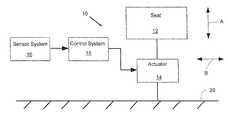
- FIG. 1is a block diagram of an active suspension system for a motor vehicle passenger seat.
- FIG. 2is a flow chart illustrating an operation of an active suspension system for a motor vehicle passenger seat.
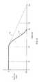
- FIG. 3illustrates an example of the vertical (z) position of a seat over time during a front-end collision.
- FIG. 4is a plot of the x-z position of the head of the occupant of a seat during a front-end collision.
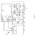
- FIG. 5is a block diagram of an active suspension system for a motor vehicle passenger seat.
- FIGS. 6A and 6B togetherare a flow chart illustrating an operation of the active suspension system for a motor vehicle passenger seat of FIG. 5 .
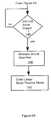
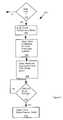
- FIG. 7is a flow chart illustrating an operation of the active suspension system for a motor vehicle passenger seat of FIG. 5 .
- FIG. 8is a block diagram of a motor vehicle network that includes the active seat.
- An active suspension system for a motor vehicle passenger seat(which is sometimes termed herein an “active seat”) can be designed and operated so as to inhibit downward motion of the seat during a front-end collision. More generally, during an accident the actuator of the active suspension system can be controlled to output a force that is proportional to the velocity of the seat.
- the active suspension systemcan also be designed and operated so as to quickly pull the seat down toward the floor during a rollover; as the rollover proceeds that seat can be moved in more than one degree of freedom in ways that counteract the seat motions caused by the rollover.
- the active seatcan communicate with existing vehicle systems over the existing vehicle data communication network.
- Embodiments of the systems and methods described herecomprise computer components and computer-implemented steps that will be apparent to those skilled in the art.
- the computer-implemented stepsmay be stored as computer-executable instructions on a computer-readable medium such as, for example, floppy disks, hard disks, optical disks, Flash ROMS, nonvolatile ROM, and RAM.
- the computer-executable instructionsmay be executed on a variety of processors such as, for example, microprocessors, digital signal processors, gate arrays, etc.
- Active suspension system 10uses actuator 14 to place forces on motor vehicle seat 12 .
- Actuator 14is coupled (either directly or indirectly) to both seat 12 and another portion of the motor vehicle, which in this non-limiting example is the cabin floor 20 .
- Actuator 14 in this exampleapplies forces linearly along first degree of freedom “A,” which here is vertically up and down. This can move (translate) the seat up and down.
- Actuator 14may be an electromagnetic actuator, for example a linear motor or a rotary actuator with a rotary to linear motion transmission, as is known in the art.
- Actuator 14can alternatively be hydraulically or pneumatically actuated.
- System 10in its typical operation uses sensor system 16 to sense accelerations of a location of the motor vehicle in this same first degree of freedom; this location is commonly the seat, the vehicle frame or the vehicle body.
- Control system 18interprets the sensed accelerations and initiates control signals that are provided to actuator 14 to counteract seat motion caused by the sensed accelerations.
- accelerationsis vibrations and jolts caused by operation and motion of the motor vehicle while driving along a road. The result of such active seat suspension is to reduce accelerations of the seat, which will decrease vertical motions of the seat caused by such vibrations and jolts.
- Sensor system 16can also sense a quantity related to motion such as accelerations (or other quantities representative of vehicle motion such as velocity in any direction, roll angle, roll rate, pitch angle, pitch rate, etc.) of the motor vehicle in second degree of freedom “B,” which is different that the first degree of freedom.
- this second degree of freedomis horizontal translation, e.g., accelerations and decelerations in the direction of travel of the motor vehicle.
- this second degree of freedomcould be any one or more of the other of the remaining five of the six degrees of freedom of the motor vehicle.
- control system 18alters controller behavior as will be described later, and/or provides control signals to actuator 14 to cause the actuator to exert forces on seat 12 in first degree of freedom A. Typically these forces are meant to accomplish a particular desired resultant motion of the seat and/or the occupant of the seat.
- An accident detection systemmay detect accident conditions by sensing accelerations and/or other motions such as rotations and/or angle, in one or more degrees of freedom, as accomplished by sensor system 16 described above.
- an accident detection systemcan determine if accident conditions are present or are imminent using other means.
- an accident detection systemuses optical, electromagnetic (i.e. radar), or other sensing means to determine if the vehicle in which the active seat resides is about to collide with another vehicle.
- the controllercan change its behavior and/or the controller can issue control commands to the actuator to output a force in response to the determination that an accident condition is either probable or imminent.
- the accident detection systemmay be incorporated as part of the active seat system, or it may be incorporated in some other part of the vehicle. In the case where the accident detection system is not incorporated in the active seat, the accident detection system is in communication with the active seat and informs the active seat controller when an accident is either probable or imminent, or when an accident is occurring.
- One use of system 10is to counteract the effects of an event that can lead to possible injury of an occupant of the vehicle, such as a head-on collision, a partial front-end collision, a side collision, a direct or partial rear-end collision, or a rollover.
- a collisioncan be determined based on sensor system 16 detecting the axis (or axes) and magnitudes of accelerations in one or more of the six degrees of freedom of the motor vehicle.
- Flow chart 30FIG. 2 , illustrates one of many possible manners in which system 10 can be operated in forward impact (i.e., front end collision) and rollover situations.
- Sensor system 16is continually monitored for unusual accelerations (events) in one or more degrees of freedom, step 32 .
- normal active suspension modewhere the suspension is used to counteract vibrations arising from normal operation of the vehicle, is maintained, step 33 .
- the controllerimplements a negative feedback loop around acceleration of the seat top in order to minimize acceleration of the seat top.
- an acceleration in any degree of freedom that is greater than a predetermined maximum normal accelerationcan be determined to be an “event”, step 32 .
- the event thresholdcan be set to 3 g (although other thresholds could be set if desired).
- the eventis characterized based on the sensed accelerations and their degrees of freedom. For example, a forward impact could be determined if a forward deceleration of at least 3 g is sensed, step 35 , and a rollover can be determined if the vehicle has rolled more than, say, 45° (i.e., the detected roll angle is greater than 45°), step 38 .
- step 36If a forward impact is detected, “crash performance mode” is entered, step 36 , and the controller behavior is altered and/or the actuator is commanded to output a force, step 37 .
- the controllermay switch behavior from implementing a negative feedback loop around acceleration of the seat to implementing a negative feedback loop around relative velocity of the seat top with respect to the vehicle floor. If the seat begins to move down in a forward impact, the result can be that the actuator is commanded to push the seat up. If a rollover is detected “crash performance mode” is entered, step 39 , and the actuator is commanded to output a force to pull the seat down, step 40 .
- the “crash performance mode”can be set to expire a pre-determined time after the event was detected; in one case the time is 200 milliseconds (mS) and is determined at step 41 . After this time the system enters the actuator passive mode, step 42 , where current to the actuator is limited to a smaller value than normal operating mode or to zero, thus de-energizing the motor. Additionally, in actuator passive mode the actuator coil power input leads may be clamped to short circuit the coils, causing the actuator to act like a passive mechanical damper.
- Some motor vehicle seat active suspension systemssuch as the Ride system available from Bose Corporation of Framingham, Mass. USA, use a four-bar seat suspension base linkage between the floor of the cabin and the seat support that supports the seat on which the passenger sits.
- the linkagesupports the seat and allows it to be moved vertically by the actuator(s).
- a vehicle with this systemexperiences a front-end collision and the person in the seat is constrained by a seatbelt which is anchored to the Bose Ride interconnection point (ICP) and to the floor just behind the seat
- the momentum of the seat and the personcauses the person's upper body to pivot forward and down about the hips.
- Thiscauses the linkage to compress and thus causes the seat to move down.
- One resultis that the occupant's head moves forward and down, thus moving the head closer to the steering wheel, the dash and deploying vehicle airbags. Such excursions of the head beyond its normal position may lead to serious head trauma.
- actuator 14comprises a linear motor with a maximum output force of 1000 Newtons (N).
- Nthe maximum output force
- the horizontal motioncouples through a 7.5 degree four-bar link to yield approximately 3000N of downward force. This can cause a downward seat velocity of about 2 meters per second (m/S).
- the actuator 14may have a vertical full stroke of about 100 mm, around nominal mid-height adjustment before it physically bottoms out. Since the seat is coupled to the actuator, during a front-end collision the front of the seat may collapse 50 mm, if the actuator was at nominal mid-height adjustment pre-crash.
- the Bose Ride systemIn “normal active suspension operation mode”, the Bose Ride system has a failsafe operating mode where the active system is switched into operation in the passive actuator mode whenever a fault is detected.
- a fault conditionwould be saturation or failure of a sensor, which could happen for a number of reasons.
- failsafe operating modethe system remains in passive mode until the fault is corrected. Once the fault is no longer present, the system reverts back to normal active suspension operation mode.
- the system accelerometersWhen an accident occurs, it is highly likely that the system accelerometers will saturate or have erroneous output.
- the output signals from inertial measurement devices such as accelerometerscannot be trusted when high acceleration or high deceleration events such as a crash event occur.
- the actuatorwould operate in its passive, clamped state as a mechanical damper. In this state, the maximum damping force provided by the actuator will be less than the available maximum force if the actuator were operated in an active state. In passive clamped state, the damping coefficient of the actuator is fixed by the actuator design.
- an actuator operated in a passive stateis less able to resist the crash forces than if it were allowed to operate in an active state. If the actuator were allowed to remain active when a crash is detected, it could, for example, be controlled to operate as a physical damper where the damping coefficient could be set arbitrarily, and could be as high as is physically possible given the maximum output force capability of the actuator.
- the controller behavioris altered such that it implements a negative feedback loop around the relative velocity of the seat top with respect to the vehicle floor. In this mode, the controller makes the system look like a physical damper where the damping coefficient is controlled in order to minimize the relative velocity of the seat top relative to the vehicle floor.
- the motorcan be operated to slow the seat downward motion by allowing the active suspension system to remain active such that the motor can output up to its full 1000N of force upon the detection of an event or crash such as a forward impact.
- the graph of FIG. 3illustrates this benefit.
- Vertical seat movement (z position)is plotted on the y axis with time in milliseconds (mS) on the x axis.
- Nominal operational vertical seat positionis at 0 mm in the z position.
- the eventbegins at 0 mS.
- the eventis detected by the control system at 20 mS. At about 60 mS the seat begins to move downward at high velocity.
- the graph of FIG. 4illustrates the occupant's head movement in the vertical (z) and horizontal (x) directions through time during the previously described front end collision.
- the motion that moves from the pre-crash position 45 , through points 46 a , 47 a and ending at 48 a(plotted as a solid line) is based on the system 10 while operating in “normal active suspension operation mode”, where upon detection of a fault condition (such as accelerometer saturation as may occur in a crash, or upon detection of a crash event by a crash event detection system), the actuator is operated in passive, clamped mode.
- a fault conditionsuch as accelerometer saturation as may occur in a crash, or upon detection of a crash event by a crash event detection system
- the maximum forward (x) excursion of the foreheadis noted by the right-most point 46 a , which is forward about 560 mm from the pre-crash position 45 and occurs at about 80-90 mS post-crash.
- the maximum vertical (z) excursion of the headis about ⁇ 350 mm (downward) at point 47 a from the pre-crash position 45 and occurs at about 120 mS post-crash. Since the maximum forward excursion of the head occurs in under 100 mS, it would be beneficial to slow the time when the seat bottoms out until after 100 mS post-crash. One result would be that the seat would bottom out after the head had begun to retract away from its forward-most point, toward end point 48 a.
- the motion that moves from the pre-crash position 45 , through points 46 b , 47 b and ending at 48 bis based on the system 10 while operating in “crash performance mode”, where the controller has been altered to implement a negative feedback loop around the relative velocity of the seat top with respect to the vehicle floor, and the actuator has remained active.
- the maximum forward (x) excursion of the foreheadis noted by the right-most point 46 b , which is less than point 46 a .
- the maximum vertical (z) excursion of the headis noted by 47 b which is less than 47 a .
- the ending point 48 bexhibits less vertical displacement and horizontal displacement as compared to 48 a .
- One result of this difference in motionis that the chances of impact with the dash or with a deploying airbag are reduced.
- System 50includes seat positioning system 51 which has two separate actuators and a variable damping coefficient damper such as a variable force shock absorber.
- Variable spring 54has a variable spring constant.
- spring 54is an air cylinder or another type of pneumatic or hydraulic system with variable force output, and is commonly used as a force bias eliminator.
- Spring 54acts as a load-leveling system whose goal is to reduce the average force that the actuator (linear motor) needs to output to control motion of the seat in the intended degree of freedom during normal operation to zero. Control to reduce the average force to zero involves both adding air and removing air from the air cylinder.
- pneumatic cylinder 54can include an electrically-operated valve 55 that can be opened to quickly expel air from the cylinder in a crash event.
- the second actuatoris linear motor 56 , which acts to place vertical forces on seat 52 to push or pull the seat in opposition to sensed vertical accelerations.
- Shock absorber 58is a damper with a variable damping coefficient. Shock absorber 58 is mounted in parallel with the actuators and is used to apply additional damping or resistive force on the seat as needed to damp seat motion, as further explained below.
- An active suspension systemcan be designed to counteract and/or damp motions in any one or more of the six degrees of freedom of the vehicle seat.
- a systemcan actively control in the vertical axis and have passive suspension systems in the X and Y axes of the horizontal plane of the seat.
- the systemmay have active control in the vertical (z) axis and the horizontal (y) lateral axis which is perpendicular to the direction of travel (x axis) of the motor vehicle.
- Typical passive suspensionsare combinations of springs and dampers. Resonant absorbers can also add damping masses.
- System 50can be arranged to counteract these excursions by using linear motor 56 to exert an upward force on seat 52 upon the detection of a front-end collision.
- This forcecan help to maintain seat 52 closer to its pre-crash vertical position than would be the case without the application of such upward force.
- This forcecan also help to maintain seat 52 in a more horizontal position; i.e., it can inhibit or at least slow the pivoting of the seat relative to the cabin floor. Either or both of these results of upward vertical force on the seat will help to decrease the forward motion of the torso and head, which can ameliorate injuries caused by the collision.
- Active suspension system 50includes inertial measurement system 60 that is coupled to seat 52 so as to sense accelerations and/or rotations of the seat along and/or about one, two or three orthogonal axes in space.
- system 60acts as inertial sensor in from one to six degrees of freedom of the seat. Its output is provided to control system 64 .
- Seat position sensor 61is not an inertial measurement instrument.
- Seat position sensor 61may employ magnetic sensors on the stator and armature of a linear motor actuator as described in U.S. Pat. No. 7,932,684 which is incorporated herein by reference. Since sensor 61 is not inertial it does not become unreliable in a crash as inertial sensors might.
- Control system 64interprets the outputs from one or both of inertial measurement system 60 and seat position sensor 61 and creates control signals that cause linear motor 56 and/or spring 54 and/or shock absorber 58 to act accordingly.
- These actionscan include placing force(s) and/or damping motions on the seat in any one or more of its six degrees of freedom (presuming that the appropriate actuators and dampers are in place so as to accomplish the forces and damping).
- One aim of such actionscan be to position the occupant in the case of an unusual event such as an impact or rollover, so that impacts of the occupant with the motor vehicle interior are less likely to occur, or their severity is lessened.
- FIGS. 6A and 6BOne example of operation of system 50 in the case of a front-end collision is illustrated by flowchart 130 , FIGS. 6A and 6B .
- the systemUpon the detection of a lateral or fore/aft acceleration greater than 3 g (e.g., forward impact 132 ) the system first enters a “crash performance mode”, step 134 . While in this mode, the system may command an amount of actuator force that is related to (e.g., proportional to) the downward velocity of the seat and that can be greater than the amount of actuator force that is normally available in the failsafe operation associated with the “normal operating mode,” up to the maximum actuator force. The faster that the seat moves downward, the greater the upward force provided by the actuator. The goal is to maintain the pre-crash vertical seat position.
- a three-axis accelerometeris mounted to this seat structure and is monitored more than 2000 times per second. From the measured acceleration, velocity and distance can be derived mathematically by the system, step 136 .
- the seat velocitycan be determined based on the derivative of the output of non-inertial seat position sensor 61 . Once the seat velocity has been determined the system can apply an appropriate current to the motor to establish the desired force.
- An airbagcan have more air pushed into it by opening the solenoids on the air input lines.
- Truck airis typically 100 pounds per square inch (psi).
- Pneumatic control systemshave slow reactance speeds. If the airbag valves were opened to add air during a crash event, this would not create enough extra force to withstand the downward force due to the event. Thus, spring 54 is not effective to maintain the vertical position of the seat in a crash.
- the vertical seat positioncan be improved by the creation of more significant opposing resistive forces, which would help to prevent the collapsing of the seating system.
- a mechanical shock absorber with a variable damping coefficient mounted in parallel with the linear motor and the springcan be used to supply the needed additional vertical resistive force.
- This shockcan be designed to not offer any substantial damping (i.e., the damping coefficient is low) during normal operation (which can in one non-limiting example be defined by a vertical seat velocity of no more than about 0.5 m/S).
- the shock's resistive forcewould be increased (i.e., its damping coefficient would be increased). If while in the crash performance mode the seat velocity is less than 0.5 m/S, the system uses only the active linear motor to oppose downward seat motion; the necessary force is calculated at step 140 .
- a magneto-rheological (MR) shockis one means of accomplishing the desired force/velocity relationship to damp downward forces of more than about 1000N.
- the damping coefficient of the shockis controlled in normal operation to result in forces in the range of 0 to about 1000N. If a forward impact is detected, step 132 , crash performance mode is entered, step 134 .
- step 138the controller operation is changed, for example to implement a negative feedback loop around the relative velocity of the seat top with respect to the vehicle floor where maximum output force of the actuator remains available, step 142 , and the additional resistive force that can be supplied by the linear motor and that is needed to counteract the downward force (to be applied by variable force shock 58 ) is calculated, step 144 .
- the control systemcan calculate how much current to apply to the MR shock to obtain a desired output force. For example, if the system was moving downward at 2 m/S, to obtain 2000N of force from the shock, about 2 A of current would be necessary.
- the seat velocitycan be determined based on the derivative of the output signal of seat position sensor 61 . In one manner of operation of the control system, a control loop on velocity may directly adjust the damping coefficient of shock 58 .
- the “crash performance mode”can be set to expire a pre-determined time after the accident or event (in this case, a front end collision) was detected; in this case the time is 200 mS and is determined at step 146 .
- the variable force shockis released (i.e., its damping coefficient is set to zero), step 148 , and the system then enters the linear motor passive mode, step 150 , where current to the motor is limited to a smaller value than normal operating mode or to zero, thus de-energizing the motor, and the motor is clamped.
- step 148is bypassed, in which case after 200 mS (step 146 ) the linear motor is commanded to enter the passive mode, step 150 .
- Flowchart 160details an example of the operation of system 50 upon detection of a rollover event, step 162 .
- the systementers crash performance mode, step 164 .
- One goal of system 50 during a rolloveris to pull the seat down as quickly as possible to help prevent the occupant from impacting the ceiling of the cabin as the vehicle rolls onto or toward its roof.
- variable force spring 54As variable force spring 54 is holding the seat up, it will inhibit downward movement of the seat.
- it is best to quickly decrease the spring constant of the springwhich in this case is done by releasing air from the air cylinder. This is done at step 166 by using control system 64 to open valve 55 , which is designed to allow air to be expelled quickly.
- step 168the linear motor is commanded to apply maximum downward force.
- step 170the motor is commanded to enter its passive, clamped mode, step 172 .
- a rollovertends to occur over a longer period of time than a collision.
- a front impactis sensed by reading the acceleration reported for the “X” axis.
- a movement in the X directionwould give a +/ ⁇ reading up to the scale of the device.
- an inertial measurement devicesuch as an accelerometer will often saturate and be subject to severe cross-axis coupling that makes it an unreliable control system input sensor.
- an accelerometercan act as an accident or crash sensor. For example, with a device that saturates at 3 g, a maximum output (e.g., 3 g) indicates an accident. Multiple samples can be taken to determine this is not an instantaneous loss of signal. Sampling of the accelerometer at 2000 times/sec, means that for a crash pulse of 100 mS, there would be 200 samples. In practicality, 10 consecutive samples would be enough to determine an accident or crash event with some amount of confidence.
- a three axis X/Y/Z accelerometer mounted to the upper mechanical structure of the seat suspension basecan be used as inertial measurement system 60 .
- the seat topis mounted.
- the accelerometeris mounted rigidly and directly below the center point of where the occupant sits.
- the X/Y/Z accelerometerprovides a digital value output that is scaled to the acceleration seen by each axis.
- Mathcan be used to determine the angle of rotation of the device relative to the “g” seen on each axis.
- An alternative means of measuring rotationwould be to use a gyroscope device (e.g., a MEMS gyro) that can output angle.
- a typical MEMS accelerometeris the KXRB5-2367, manufactured by Kionix, Inc.
- a typical MEMS combined gyroscope and accelerometeris the MPU-6500, manufactured by InvenSense, Inc.
- a rollovercan be sensed by deducing using calculations the angle of rotation as reported by the X/Y/Z accelerometer, or by other methods known in the art. For example, if the accelerometer was rotated in one axis, a reading of less than 1 g would be measurable. Math can be used to map the acceleration in an axis to an angle of rotation.
- a MEMS gyroscopecan provide both a 3 axis gyroscope and 3 axis accelerometer. The determination that a forward impact has occurred can be based on when acceleration of more than 3 g is sustained for a period of samples. The determination that a rollover has occurred can be when a certain angle has been exceeded from an upright vertical position reading, e.g., 45 degrees.
- Motor vehicle network 200comprises active seat 202 that is in data communication with existing motor vehicle systems such as collision avoidance system 204 , airbag deployment system 206 , black box 208 , information center 210 , hazard lights 212 and collision detection system 216 .
- existing motor vehicle systemssuch as collision avoidance system 204 , airbag deployment system 206 , black box 208 , information center 210 , hazard lights 212 and collision detection system 216 .
- One or more of such systemscommunicates with one or more other such systems over existing vehicle data network 214 , which typically uses an existing networking convention such as the controller area network (CAN) vehicle bus standard or the local interconnect network (LIN), general purpose input/outputs (GPIO) or other existing motor vehicle communication standards as are known in the art.
- CANcontroller area network
- LINlocal interconnect network
- GPIOgeneral purpose input/outputs
- the collision avoidance system 204in response to detecting an imminent frontal impact crash, communicates such a status to the active seat system 202 via vehicle network 214 .
- the active seat systemcould move the seat up from the pre-status vertical position so as to provide greater range of controlled downward motion after the crash before the seat may reach the bottom limit of vertical mechanical travel.
- Another benefit of moving the seat up before an imminent frontal impact crashis that there is less seat belt restraint system webbing out of the spool and that reduces the amount of webbing stretch that contributes to frontal excursion of the occupant towards the steering wheel.
- a MR dampercould be turned on to further resist any downward motion, as described above.
- the collision detection system 216 or an inertial sensor or another motion and/or force sensoris mounted in the trailer and/or in the trailer/cab coupling of a tractor trailer that has a separate cab
- an imminent tipping of the trailercould be detected based on a rolling motion greater than a threshold rolling motion.
- the sensor(s)would be in communication with the active seat controller. The detection could take place prior to the roll-over of the cab that the occupant is in.
- proactive positioning of the occupantcan be achieved using the active seat to move the occupant towards an optimal position away from the roll-over side and pulling the seat downwards.
- the imminent rollovercould be reported and could potentially be counteracted.
- the active seat system 202may sense and then communicate such information to an airbag deployment system 206 so as to sequence the deployments of airbags surrounding the occupant in a manner that provides maximum protection to the side of impact. For example, when a truck rolls to the left, then onto the roof, then again to the left (and so onto the right side), the airbag deployed sequence may be to deploy left-side airbag, then right-side airbag. The deployment can be timed relative to the rolling so that the airbag inflation occurs when the occupant is being thrown to the side where the airbag is being inflated. This can be done in addition to actuated seat motions as described above.
- the active seat system 202may indicate the detection of a collision to a hazard light controller 212 so that hazard lights can be turned on.
Landscapes
- Engineering & Computer Science (AREA)
- General Engineering & Computer Science (AREA)
- Aviation & Aerospace Engineering (AREA)
- Mechanical Engineering (AREA)
- Physics & Mathematics (AREA)
- Acoustics & Sound (AREA)
- Transportation (AREA)
- Seats For Vehicles (AREA)
Abstract
Description
Claims (21)
Priority Applications (6)
| Application Number | Priority Date | Filing Date | Title |
|---|---|---|---|
| US13/927,900US9199563B2 (en) | 2013-06-04 | 2013-06-26 | Active suspension of a motor vehicle passenger seat |
| EP14733898.2AEP3003778B1 (en) | 2013-06-04 | 2014-05-30 | Active suspension of a motor vehicle passenger seat |
| PCT/US2014/040229WO2014197312A1 (en) | 2013-06-04 | 2014-05-30 | Active suspension of a motor vehicle passenger seat |
| CA2912865ACA2912865C (en) | 2013-06-04 | 2014-05-30 | Active suspension of a motor vehicle passenger seat |
| US14/936,625US9358910B2 (en) | 2013-06-04 | 2015-11-09 | Active suspension of a motor vehicle passenger seat |
| US15/174,474US9527415B2 (en) | 2013-06-04 | 2016-06-06 | Active suspension of a motor vehicle passenger seat |
Applications Claiming Priority (2)
| Application Number | Priority Date | Filing Date | Title |
|---|---|---|---|
| US201361830936P | 2013-06-04 | 2013-06-04 | |
| US13/927,900US9199563B2 (en) | 2013-06-04 | 2013-06-26 | Active suspension of a motor vehicle passenger seat |
Related Child Applications (1)
| Application Number | Title | Priority Date | Filing Date |
|---|---|---|---|
| US14/936,625ContinuationUS9358910B2 (en) | 2013-06-04 | 2015-11-09 | Active suspension of a motor vehicle passenger seat |
Publications (2)
| Publication Number | Publication Date |
|---|---|
| US20140358378A1 US20140358378A1 (en) | 2014-12-04 |
| US9199563B2true US9199563B2 (en) | 2015-12-01 |
Family
ID=51986042
Family Applications (3)
| Application Number | Title | Priority Date | Filing Date |
|---|---|---|---|
| US13/927,900Active2033-09-22US9199563B2 (en) | 2013-06-04 | 2013-06-26 | Active suspension of a motor vehicle passenger seat |
| US14/936,625ActiveUS9358910B2 (en) | 2013-06-04 | 2015-11-09 | Active suspension of a motor vehicle passenger seat |
| US15/174,474ActiveUS9527415B2 (en) | 2013-06-04 | 2016-06-06 | Active suspension of a motor vehicle passenger seat |
Family Applications After (2)
| Application Number | Title | Priority Date | Filing Date |
|---|---|---|---|
| US14/936,625ActiveUS9358910B2 (en) | 2013-06-04 | 2015-11-09 | Active suspension of a motor vehicle passenger seat |
| US15/174,474ActiveUS9527415B2 (en) | 2013-06-04 | 2016-06-06 | Active suspension of a motor vehicle passenger seat |
Country Status (4)
| Country | Link |
|---|---|
| US (3) | US9199563B2 (en) |
| EP (1) | EP3003778B1 (en) |
| CA (1) | CA2912865C (en) |
| WO (1) | WO2014197312A1 (en) |
Cited By (9)
| Publication number | Priority date | Publication date | Assignee | Title |
|---|---|---|---|---|
| US20180105082A1 (en)* | 2016-10-17 | 2018-04-19 | Bose Corporation | Active Vibration Isolation System |
| US20190118680A1 (en)* | 2017-10-25 | 2019-04-25 | Tencate Advanced Armor Usa, Inc. | Advanced active crash seat systems and methods |
| US11046266B1 (en) | 2018-06-04 | 2021-06-29 | State Farm Mutual Automobile Insurance Company | System and method for dampening impact to a vehicle |
| US11352017B2 (en) | 2018-07-13 | 2022-06-07 | State Farm Mutual Automobile Insurance Company | Dynamic safe storage of vehicle content |
| US11400834B2 (en) | 2018-02-02 | 2022-08-02 | State Farm Mutual Automobile Insurance Company | Adjusting interior configuration of a vehicle based on external environment data |
| US20220314725A1 (en)* | 2021-04-02 | 2022-10-06 | Toyota Jidosha Kabushiki Kaisha | Vehicle control device |
| US11485254B2 (en)* | 2018-04-09 | 2022-11-01 | State Farm Mutual Automobile Insurance Company | System and method for adjusting an interior configuration of a vehicle in response to a vehicular accident |
| US11554736B2 (en)* | 2018-07-13 | 2023-01-17 | State Farm Mutual Automobile Insurance Company | Adjusting interior configuration of a vehicle based on vehicle contents |
| US11840243B2 (en) | 2018-07-13 | 2023-12-12 | State Farm Mutual Automobile Insurance Company | Dynamic limiting of vehicle operation based on interior configurations |
Families Citing this family (48)
| Publication number | Priority date | Publication date | Assignee | Title |
|---|---|---|---|---|
| EP3626485B1 (en) | 2013-03-15 | 2024-05-29 | ClearMotion, Inc. | Active vehicle suspension improvements |
| WO2014152482A2 (en) | 2013-03-15 | 2014-09-25 | Levant Power Corporation | Multi-path fluid diverter valve |
| US9459097B2 (en)* | 2014-03-12 | 2016-10-04 | John S Davey | Tilt sensing apparatus, system and method for using same |
| EP4491421A3 (en) | 2014-04-02 | 2025-04-02 | ClearMotion, Inc. | Active safety suspension system |
| DE112015000157T5 (en)* | 2014-06-17 | 2016-05-25 | Mazda Motor Corporation | Vehicle emergency alarm device |
| US10300760B1 (en) | 2015-03-18 | 2019-05-28 | Apple Inc. | Fully-actuated suspension system |
| JP6197815B2 (en)* | 2015-03-19 | 2017-09-20 | トヨタ自動車株式会社 | Occupant protection control device, occupant protection control program, and vehicle |
| US20170083857A1 (en) | 2015-09-17 | 2017-03-23 | James D. Barton | Gps shipping and temperature sensor label |
| US10518674B1 (en)* | 2015-09-28 | 2019-12-31 | Apple Inc. | Passive safety system for occupant deceleration |
| US9944206B2 (en) | 2015-11-06 | 2018-04-17 | Clearmotion Acquisition I Llc | Controlling active isolation platform in a moving vehicle |
| US9758073B2 (en) | 2015-11-06 | 2017-09-12 | Bose Corporation | Variable gain control in roll compensating seat |
| US9902300B2 (en) | 2015-11-06 | 2018-02-27 | Clearmotion Acquisition I Llc | Lean-in cornering platform for a moving vehicle |
| US10029586B2 (en)* | 2015-11-06 | 2018-07-24 | Clearmotion Acquisition I Llc | Vehicle seat with angle trajectory planning during large events |
| US10118516B2 (en)* | 2015-12-02 | 2018-11-06 | Agco Corporation | Vehicle seat operation feedback and control |
| DE102015225136A1 (en)* | 2015-12-14 | 2017-06-14 | Robert Bosch Gmbh | Method, electronic control device and position determining system |
| US10035439B2 (en) | 2016-03-02 | 2018-07-31 | Clearmotion Acquisition I Llc | Vehicle seat active suspension control based on vehicle position |
| DE102016216653A1 (en) | 2016-09-02 | 2018-03-08 | Volkswagen Aktiengesellschaft | Active vehicle seat system and method for operating an active vehicle seat system |
| US10814690B1 (en) | 2017-04-18 | 2020-10-27 | Apple Inc. | Active suspension system with energy storage device |
| JP2020518514A (en) | 2017-05-08 | 2020-06-25 | アップル インコーポレイテッドApple Inc. | Active suspension system |
| US10899340B1 (en) | 2017-06-21 | 2021-01-26 | Apple Inc. | Vehicle with automated subsystems |
| US11173766B1 (en) | 2017-09-07 | 2021-11-16 | Apple Inc. | Suspension system with locking structure |
| US10906370B1 (en) | 2017-09-15 | 2021-02-02 | Apple Inc. | Active suspension system |
| US11124035B1 (en) | 2017-09-25 | 2021-09-21 | Apple Inc. | Multi-stage active suspension actuator |
| US10960723B1 (en) | 2017-09-26 | 2021-03-30 | Apple Inc. | Wheel-mounted suspension actuators |
| US20210268942A1 (en)* | 2018-05-15 | 2021-09-02 | Clearmotion Acquisition I Llc | Active seat suspension failsafe operation |
| JP6888587B2 (en)* | 2018-05-31 | 2021-06-16 | トヨタ自動車株式会社 | Seat control device |
| US11685303B2 (en) | 2018-08-31 | 2023-06-27 | Daniel R. Brettschneider | Berth apparatus and methods using physiological parameters for controlling berth motion to promote relaxation and to induce sleep |
| US11285773B1 (en) | 2018-09-12 | 2022-03-29 | Apple Inc. | Control system |
| US11667216B2 (en)* | 2018-09-13 | 2023-06-06 | Volvo Truck Corporation | Dynamic backward seat sliding after impact in a commercial vehicle |
| US11634167B1 (en) | 2018-09-14 | 2023-04-25 | Apple Inc. | Transmitting axial and rotational movement to a hub |
| WO2020087088A2 (en)* | 2018-09-25 | 2020-04-30 | Ceva Technologies, Inc. | Methods and apparatus for calibrating the zero rate output of a sensor |
| US11345209B1 (en) | 2019-06-03 | 2022-05-31 | Apple Inc. | Suspension systems |
| US11279307B2 (en)* | 2019-08-26 | 2022-03-22 | Lear Corporation | Seat arrangement with dynamic seat positioning system |
| US11179991B1 (en) | 2019-09-23 | 2021-11-23 | Apple Inc. | Suspension systems |
| US11938922B1 (en) | 2019-09-23 | 2024-03-26 | Apple Inc. | Motion control system |
| US11400840B2 (en)* | 2019-11-06 | 2022-08-02 | Steering Solutions Ip Holding Corporation | System and method for seat vibration cancellation |
| US11707961B1 (en) | 2020-04-28 | 2023-07-25 | Apple Inc. | Actuator with reinforcing structure for torsion resistance |
| US11828339B1 (en) | 2020-07-07 | 2023-11-28 | Apple Inc. | Vibration control system |
| GB2597457B (en)* | 2020-07-21 | 2023-02-01 | Jaguar Land Rover Ltd | Vehicle active suspension control system and method |
| US11820275B2 (en) | 2020-10-30 | 2023-11-21 | Daniel R. Brettschneider | Carrier platform with suspension mechanism for supporting a vibration-sensitive load on a vehicle |
| JP2022150744A (en)* | 2021-03-26 | 2022-10-07 | 株式会社Subaru | vehicle seat |
| US12017498B2 (en) | 2021-06-07 | 2024-06-25 | Apple Inc. | Mass damper system |
| US11814177B2 (en) | 2021-07-16 | 2023-11-14 | B/E Aerospace, Inc. | Seat with enhanced response |
| US12054081B2 (en)* | 2022-03-28 | 2024-08-06 | B/E Aerospace, Inc. | Seat pan impulse device for the reduction of spinal tension loads resulting from a free flail event |
| US12251973B2 (en) | 2022-06-10 | 2025-03-18 | Apple Inc. | Vibration absorber |
| DE102022214318A1 (en) | 2022-12-22 | 2024-06-27 | Robert Bosch Gesellschaft mit beschränkter Haftung | Control of small electric drives in vehicle seats and other adjustable vehicle elements for their active position fixation or stabilization and for limiting crash forces |
| DE102022214322A1 (en) | 2022-12-22 | 2024-06-27 | Robert Bosch Gesellschaft mit beschränkter Haftung | Redundant IMU detection of position and orientation for actuator systems in the vehicle interior using filter algorithms on IMU data |
| US12168375B1 (en) | 2023-01-26 | 2024-12-17 | Apple Inc. | Motion control system |
Citations (51)
| Publication number | Priority date | Publication date | Assignee | Title |
|---|---|---|---|---|
| US4272117A (en) | 1976-12-08 | 1981-06-09 | Sifra | Seat with damped suspension system |
| US4289351A (en) | 1979-10-01 | 1981-09-15 | The Freedman Seating Company | Low profile truck seat |
| US4291857A (en) | 1979-11-09 | 1981-09-29 | Allis-Chalmers Corporation | Vehicle seat suspension |
| US4363377A (en) | 1980-09-22 | 1982-12-14 | Deere & Company | Active seat suspension control system |
| US4728873A (en) | 1986-07-28 | 1988-03-01 | Toyota Jidosha Kabushiki Kaisha | Automatic seat position adjusting assembly |
| US4913482A (en) | 1985-09-30 | 1990-04-03 | Mitsubishi Denki Kabushiki Kaisha | Seat suspension system for automotive vehicle or the like |
| US5004967A (en) | 1990-03-16 | 1991-04-02 | Tachi-S Co., Ltd. | Method and device for controlling slide motion of a vehicle seat |
| EP0232647B1 (en) | 1985-12-17 | 1991-07-03 | André Molinier | Oscillating seat support apparatus with a hydropneumatic suspension for all-terrain vehicles |
| WO1994021487A1 (en) | 1993-03-17 | 1994-09-29 | Rosdon Engineering & Manufacturing Pty. Ltd. | Vehicle seat suspension unit |
| US5358305A (en) | 1987-08-13 | 1994-10-25 | Nissan Motor Co., Ltd. | Suspension system for automotive vehicle or the like |
| US5451094A (en) | 1994-06-27 | 1995-09-19 | Indiana Mills & Manufacturing, Inc. | Seat and occupant restraint system |
| EP0672549A2 (en) | 1994-03-14 | 1995-09-20 | Trw Inc. | Method and apparatus for controlling an active suspension system |
| MX9503384A (en) | 1995-08-07 | 1997-02-28 | Indiana Mills & Mfg | Restriction system for a vehicle seat and occupant. |
| US5652704A (en) | 1995-09-12 | 1997-07-29 | Lord Corporation | Controllable seat damper system and control method therefor |
| US5876085A (en) | 1997-02-27 | 1999-03-02 | Milsco Manufacturing Company | Adjustable vehicle seat |
| US5975508A (en) | 1995-09-06 | 1999-11-02 | Applied Power Inc. | Active vehicle seat suspension system |
| US6014602A (en) | 1994-09-23 | 2000-01-11 | Advanced Safety Concepts, Inc. | Motor vehicle occupant sensing systems |
| US6059253A (en) | 1996-05-14 | 2000-05-09 | Sears Manufacturing Company | Active suspension system for vehicle seats |
| US6070681A (en) | 1997-06-13 | 2000-06-06 | Lord Corporation | Controllable cab suspension |
| US6082715A (en) | 1999-03-09 | 2000-07-04 | Navistar International Transportation Corp | Integrated semi-active seat suspension and seat lockup system |
| US6120082A (en) | 1999-03-09 | 2000-09-19 | Navistar International Transportation Corp. | Integrated active seat suspension and seat lockup device |
| US6212455B1 (en) | 1998-12-03 | 2001-04-03 | Indiana Mills & Manufacturing, Inc. | Roll sensor system for a vehicle |
| US6213567B1 (en) | 1998-02-02 | 2001-04-10 | Siemens Aktiengesellschaft | Brake system for a motor vehicle and method for transmitting data in an electrically controlled brake system for a motor vehicle |
| US6264163B1 (en) | 1996-08-27 | 2001-07-24 | Be-Ge Industri Aktiebolag | Vehicle seat |
| DE10015273A1 (en) | 2000-03-28 | 2001-10-11 | Siemens Ag | Accident protection device control system e.g. for motor vehicle |
| US6312015B1 (en) | 1997-11-05 | 2001-11-06 | Indiana Mills & Manufacturing, Inc. | Clamp for retractor belt |
| WO2001083261A1 (en) | 2000-05-03 | 2001-11-08 | Lord Corporation | Method for adjusting the gain applied to a seat suspension control signal |
| US6322140B1 (en) | 1994-06-27 | 2001-11-27 | Indiana Mills & Manufacturing, Inc. | Seat and occupant restraint system |
| US6328379B1 (en) | 2000-03-20 | 2001-12-11 | Indiana Mills And Manufacturing, Inc. | Vehicle restraint system with slidable seat |
| EP1188608A1 (en) | 2000-09-05 | 2002-03-20 | Deere & Company | Active suspension with offload adjustment |
| US6382718B1 (en) | 1998-12-24 | 2002-05-07 | Daimlerchrysler Ag | Automatically fastenable vehicle seat |
| US20020145315A1 (en) | 2000-10-25 | 2002-10-10 | Fraley Gregory S. | Energy management device for vehicle |
| US6582015B2 (en) | 2000-08-17 | 2003-06-24 | Chris P. Jessup | Seat and occupant restraint system with adaptable actuator |
| US6585240B1 (en) | 1999-08-19 | 2003-07-01 | Delta Tooling Co., Ltd. | Vibration relief apparatus and magnetic damper mechanism therefor |
| US6600985B2 (en) | 2001-03-26 | 2003-07-29 | Indiana Mills & Manufacturing, Inc. | Roll sensor system for a vehicle |
| US6637816B2 (en) | 2001-03-09 | 2003-10-28 | Visteon Global Technologies, Inc. | Seating system for a vehicle having a deceleration sensor |
| US20030222386A1 (en) | 2001-11-27 | 2003-12-04 | Markus Duerre | Combined spring seat isolator and mass damper |
| US6719258B2 (en) | 2002-09-16 | 2004-04-13 | Activar, Inc. | Shock and vibration isolation apparatus for motor vehicles seats |
| WO2005102112A2 (en) | 2004-04-15 | 2005-11-03 | Indiana Mills & Manufacturing, Inc. | Adjustable height vehicle seat bottom |
| DE102005011856B3 (en) | 2005-03-15 | 2006-08-31 | Isringhausen Gmbh & Co. Kg | Seat with horizontal suspension for vehicle has a vertical or pneumatic shock absorber of vertical system connected to that of the horizontal system |
| US20060253240A1 (en)* | 2005-05-06 | 2006-11-09 | Ford Global Technologies, Llc | Occupant control system integrated with vehicle dynamics controls |
| US20060261647A1 (en) | 2002-12-12 | 2006-11-23 | Daimlerchrysler Ag | Vehicle seat provided with an active suspension with two degrees of freedom of motion |
| US20080252114A1 (en) | 2007-04-16 | 2008-10-16 | Volvo Construction Equipment Holding Sweden Ab. | Seat for heavy equipment having buffer means in forward and backward directions |
| US7810779B2 (en) | 2006-08-10 | 2010-10-12 | Indiana Mills & Manufacturing Inc. | Apparatus for preventing actuation of a vehicle seat position adjustment device |
| DE102009017957A1 (en) | 2009-04-15 | 2011-01-05 | Keiper Gmbh & Co. Kg | Compensation device for compensating vertical movements of seat of commercial motor vehicle, has actuator device comprising traction actuator that exerts traction force and increases force when pressure applied on actuator is increased |
| US20110035118A1 (en)* | 2007-02-02 | 2011-02-10 | Gregory Hiemenz | Method of determining impact severity and adaptive impact attenuation |
| US7932684B2 (en) | 2008-03-25 | 2011-04-26 | Bose Corporation | Absolute position sensing |
| US7976092B2 (en) | 2004-10-19 | 2011-07-12 | Indiana Mills & Manufacturing Inc. | Vehicle safety seat |
| US8095268B2 (en) | 2004-10-29 | 2012-01-10 | Bose Corporation | Active suspending |
| US20130325323A1 (en)* | 1998-10-22 | 2013-12-05 | American Vehicular Sciences | Vehicle software upgrade techniques |
| US20140097957A1 (en)* | 1995-06-07 | 2014-04-10 | American Vehicular Sciences Llc | Driver fatigue monitoring system and method |
- 2013
- 2013-06-26USUS13/927,900patent/US9199563B2/enactiveActive
- 2014
- 2014-05-30EPEP14733898.2Apatent/EP3003778B1/enactiveActive
- 2014-05-30CACA2912865Apatent/CA2912865C/enactiveActive
- 2014-05-30WOPCT/US2014/040229patent/WO2014197312A1/enactiveApplication Filing
- 2015
- 2015-11-09USUS14/936,625patent/US9358910B2/enactiveActive
- 2016
- 2016-06-06USUS15/174,474patent/US9527415B2/enactiveActive
Patent Citations (54)
| Publication number | Priority date | Publication date | Assignee | Title |
|---|---|---|---|---|
| US4272117A (en) | 1976-12-08 | 1981-06-09 | Sifra | Seat with damped suspension system |
| US4289351A (en) | 1979-10-01 | 1981-09-15 | The Freedman Seating Company | Low profile truck seat |
| US4291857A (en) | 1979-11-09 | 1981-09-29 | Allis-Chalmers Corporation | Vehicle seat suspension |
| US4363377A (en) | 1980-09-22 | 1982-12-14 | Deere & Company | Active seat suspension control system |
| US4913482A (en) | 1985-09-30 | 1990-04-03 | Mitsubishi Denki Kabushiki Kaisha | Seat suspension system for automotive vehicle or the like |
| EP0232647B1 (en) | 1985-12-17 | 1991-07-03 | André Molinier | Oscillating seat support apparatus with a hydropneumatic suspension for all-terrain vehicles |
| US4728873A (en) | 1986-07-28 | 1988-03-01 | Toyota Jidosha Kabushiki Kaisha | Automatic seat position adjusting assembly |
| US5358305A (en) | 1987-08-13 | 1994-10-25 | Nissan Motor Co., Ltd. | Suspension system for automotive vehicle or the like |
| US5004967A (en) | 1990-03-16 | 1991-04-02 | Tachi-S Co., Ltd. | Method and device for controlling slide motion of a vehicle seat |
| WO1994021487A1 (en) | 1993-03-17 | 1994-09-29 | Rosdon Engineering & Manufacturing Pty. Ltd. | Vehicle seat suspension unit |
| EP0672549A2 (en) | 1994-03-14 | 1995-09-20 | Trw Inc. | Method and apparatus for controlling an active suspension system |
| US5451094A (en) | 1994-06-27 | 1995-09-19 | Indiana Mills & Manufacturing, Inc. | Seat and occupant restraint system |
| US6322140B1 (en) | 1994-06-27 | 2001-11-27 | Indiana Mills & Manufacturing, Inc. | Seat and occupant restraint system |
| US6014602A (en) | 1994-09-23 | 2000-01-11 | Advanced Safety Concepts, Inc. | Motor vehicle occupant sensing systems |
| US20140097957A1 (en)* | 1995-06-07 | 2014-04-10 | American Vehicular Sciences Llc | Driver fatigue monitoring system and method |
| MX9503384A (en) | 1995-08-07 | 1997-02-28 | Indiana Mills & Mfg | Restriction system for a vehicle seat and occupant. |
| US5975508A (en) | 1995-09-06 | 1999-11-02 | Applied Power Inc. | Active vehicle seat suspension system |
| US5652704A (en) | 1995-09-12 | 1997-07-29 | Lord Corporation | Controllable seat damper system and control method therefor |
| US6059253A (en) | 1996-05-14 | 2000-05-09 | Sears Manufacturing Company | Active suspension system for vehicle seats |
| US6264163B1 (en) | 1996-08-27 | 2001-07-24 | Be-Ge Industri Aktiebolag | Vehicle seat |
| US5876085A (en) | 1997-02-27 | 1999-03-02 | Milsco Manufacturing Company | Adjustable vehicle seat |
| US6070681A (en) | 1997-06-13 | 2000-06-06 | Lord Corporation | Controllable cab suspension |
| US6312015B1 (en) | 1997-11-05 | 2001-11-06 | Indiana Mills & Manufacturing, Inc. | Clamp for retractor belt |
| US6213567B1 (en) | 1998-02-02 | 2001-04-10 | Siemens Aktiengesellschaft | Brake system for a motor vehicle and method for transmitting data in an electrically controlled brake system for a motor vehicle |
| US20130325323A1 (en)* | 1998-10-22 | 2013-12-05 | American Vehicular Sciences | Vehicle software upgrade techniques |
| US6212455B1 (en) | 1998-12-03 | 2001-04-03 | Indiana Mills & Manufacturing, Inc. | Roll sensor system for a vehicle |
| US6382718B1 (en) | 1998-12-24 | 2002-05-07 | Daimlerchrysler Ag | Automatically fastenable vehicle seat |
| US6193297B1 (en) | 1999-03-09 | 2001-02-27 | Navistar International Transportation Corp. | Integrated active seat suspension and seat lockup device |
| US6120082A (en) | 1999-03-09 | 2000-09-19 | Navistar International Transportation Corp. | Integrated active seat suspension and seat lockup device |
| US6082715A (en) | 1999-03-09 | 2000-07-04 | Navistar International Transportation Corp | Integrated semi-active seat suspension and seat lockup system |
| US6585240B1 (en) | 1999-08-19 | 2003-07-01 | Delta Tooling Co., Ltd. | Vibration relief apparatus and magnetic damper mechanism therefor |
| US6328379B1 (en) | 2000-03-20 | 2001-12-11 | Indiana Mills And Manufacturing, Inc. | Vehicle restraint system with slidable seat |
| DE10015273A1 (en) | 2000-03-28 | 2001-10-11 | Siemens Ag | Accident protection device control system e.g. for motor vehicle |
| WO2001083261A1 (en) | 2000-05-03 | 2001-11-08 | Lord Corporation | Method for adjusting the gain applied to a seat suspension control signal |
| US6582015B2 (en) | 2000-08-17 | 2003-06-24 | Chris P. Jessup | Seat and occupant restraint system with adaptable actuator |
| EP1188608A1 (en) | 2000-09-05 | 2002-03-20 | Deere & Company | Active suspension with offload adjustment |
| US20020145315A1 (en) | 2000-10-25 | 2002-10-10 | Fraley Gregory S. | Energy management device for vehicle |
| US6637816B2 (en) | 2001-03-09 | 2003-10-28 | Visteon Global Technologies, Inc. | Seating system for a vehicle having a deceleration sensor |
| US6600985B2 (en) | 2001-03-26 | 2003-07-29 | Indiana Mills & Manufacturing, Inc. | Roll sensor system for a vehicle |
| US20030222386A1 (en) | 2001-11-27 | 2003-12-04 | Markus Duerre | Combined spring seat isolator and mass damper |
| EP1362748B1 (en) | 2002-05-13 | 2006-08-09 | INDIANA MILLS & MANUFACTURING, INC. | Roll sensor system for a vehicle |
| US6719258B2 (en) | 2002-09-16 | 2004-04-13 | Activar, Inc. | Shock and vibration isolation apparatus for motor vehicles seats |
| US20060261647A1 (en) | 2002-12-12 | 2006-11-23 | Daimlerchrysler Ag | Vehicle seat provided with an active suspension with two degrees of freedom of motion |
| WO2005102112A2 (en) | 2004-04-15 | 2005-11-03 | Indiana Mills & Manufacturing, Inc. | Adjustable height vehicle seat bottom |
| US7976092B2 (en) | 2004-10-19 | 2011-07-12 | Indiana Mills & Manufacturing Inc. | Vehicle safety seat |
| US8095268B2 (en) | 2004-10-29 | 2012-01-10 | Bose Corporation | Active suspending |
| DE102005011856B3 (en) | 2005-03-15 | 2006-08-31 | Isringhausen Gmbh & Co. Kg | Seat with horizontal suspension for vehicle has a vertical or pneumatic shock absorber of vertical system connected to that of the horizontal system |
| US20060253240A1 (en)* | 2005-05-06 | 2006-11-09 | Ford Global Technologies, Llc | Occupant control system integrated with vehicle dynamics controls |
| US7810779B2 (en) | 2006-08-10 | 2010-10-12 | Indiana Mills & Manufacturing Inc. | Apparatus for preventing actuation of a vehicle seat position adjustment device |
| US20110035118A1 (en)* | 2007-02-02 | 2011-02-10 | Gregory Hiemenz | Method of determining impact severity and adaptive impact attenuation |
| US20080252114A1 (en) | 2007-04-16 | 2008-10-16 | Volvo Construction Equipment Holding Sweden Ab. | Seat for heavy equipment having buffer means in forward and backward directions |
| EP1982864A2 (en) | 2007-04-16 | 2008-10-22 | Volvo Construction Equipment Holding Sweden AB | Seat for heavy equipment having buffer means in forward and backward directions |
| US7932684B2 (en) | 2008-03-25 | 2011-04-26 | Bose Corporation | Absolute position sensing |
| DE102009017957A1 (en) | 2009-04-15 | 2011-01-05 | Keiper Gmbh & Co. Kg | Compensation device for compensating vertical movements of seat of commercial motor vehicle, has actuator device comprising traction actuator that exerts traction force and increases force when pressure applied on actuator is increased |
Non-Patent Citations (9)
| Title |
|---|
| Chinese 5th Office Action dated Aug. 19, 2013 for Chinese Application No. 200880125303.9. |
| First Chinese Office Action dated Mar. 12, 2012 for Chinese Application No. 200880125303.9. |
| Fourth Chinese Office Action dated Apr. 17, 2013 for Chinese Application No. 200880125303.9. |
| http://www.imminet.com/products/rolltek/ as downloaded on Nov. 21, 2013; "When you are in the middle of one of the most devastating accidents, RollTek can offer you increased protection in a fraction of a second." |
| International Preliminary Report on Patentability dated Aug. 19, 2010 for PCT Application No. PCT/US2008/084533. |
| International Search Report and Written Opinion dated Mar. 26, 2009 for PCT Application No. PCT/US2008/084533. |
| Second Chinese Office Action dated Aug. 27, 2012 for Application No. 200880125303.9. |
| The International Search Report and the Written Opinion of the International Searching Authority mailed on Oct. 8, 2014 for the corresponding PCT Application No. PCT/US2014/040229. |
| Third Chinese Office Action dated Dec. 28, 2012 for Chinese Application No. 200880125303.9. |
Cited By (17)
| Publication number | Priority date | Publication date | Assignee | Title |
|---|---|---|---|---|
| US10675999B2 (en)* | 2016-10-17 | 2020-06-09 | Clearmotion Acquisition I Llc | Active vibration isolation system |
| US20180105082A1 (en)* | 2016-10-17 | 2018-04-19 | Bose Corporation | Active Vibration Isolation System |
| US20190118680A1 (en)* | 2017-10-25 | 2019-04-25 | Tencate Advanced Armor Usa, Inc. | Advanced active crash seat systems and methods |
| US11400834B2 (en) | 2018-02-02 | 2022-08-02 | State Farm Mutual Automobile Insurance Company | Adjusting interior configuration of a vehicle based on external environment data |
| US11485254B2 (en)* | 2018-04-09 | 2022-11-01 | State Farm Mutual Automobile Insurance Company | System and method for adjusting an interior configuration of a vehicle in response to a vehicular accident |
| US12024069B2 (en) | 2018-04-09 | 2024-07-02 | State Farm Mutual Automobile Insurance Company | System and method for adjusting an interior configuration of a vehicle in response to a vehicular accident |
| US11046266B1 (en) | 2018-06-04 | 2021-06-29 | State Farm Mutual Automobile Insurance Company | System and method for dampening impact to a vehicle |
| US11820306B2 (en) | 2018-06-04 | 2023-11-21 | State Farm Mutual Automobile Insurance Company | System and method for dampening impact to a vehicle |
| US11352017B2 (en) | 2018-07-13 | 2022-06-07 | State Farm Mutual Automobile Insurance Company | Dynamic safe storage of vehicle content |
| US11554736B2 (en)* | 2018-07-13 | 2023-01-17 | State Farm Mutual Automobile Insurance Company | Adjusting interior configuration of a vehicle based on vehicle contents |
| US11623651B2 (en) | 2018-07-13 | 2023-04-11 | State Farm Mutual Automobile Insurance Company | Dynamic safe storage of vehicle content |
| US11840243B2 (en) | 2018-07-13 | 2023-12-12 | State Farm Mutual Automobile Insurance Company | Dynamic limiting of vehicle operation based on interior configurations |
| US12005910B2 (en) | 2018-07-13 | 2024-06-11 | State Farm Mutual Automobile Insurance Company | Dynamic safe storage of vehicle content |
| US12128842B2 (en) | 2018-07-13 | 2024-10-29 | State Farm Mutual Automobile Insurance Company | Adjusting interior configuration of a vehicle based on vehicle contents |
| CN115195555A (en)* | 2021-04-02 | 2022-10-18 | 丰田自动车株式会社 | Vehicle control device |
| US12017497B2 (en)* | 2021-04-02 | 2024-06-25 | Toyota Jidosha Kabushiki Kaisha | Vehicle control device |
| US20220314725A1 (en)* | 2021-04-02 | 2022-10-06 | Toyota Jidosha Kabushiki Kaisha | Vehicle control device |
Also Published As
| Publication number | Publication date |
|---|---|
| US20160280104A1 (en) | 2016-09-29 |
| US20160059755A1 (en) | 2016-03-03 |
| EP3003778A1 (en) | 2016-04-13 |
| EP3003778B1 (en) | 2020-05-06 |
| US9527415B2 (en) | 2016-12-27 |
| WO2014197312A1 (en) | 2014-12-11 |
| CA2912865A1 (en) | 2014-12-11 |
| CA2912865C (en) | 2019-07-09 |
| US9358910B2 (en) | 2016-06-07 |
| US20140358378A1 (en) | 2014-12-04 |
Similar Documents
| Publication | Publication Date | Title |
|---|---|---|
| US9527415B2 (en) | Active suspension of a motor vehicle passenger seat | |
| US8554461B2 (en) | System and method for pre-deploying restraints countermeasures using pre-crash sensing and post-crash sensing | |
| KR101611087B1 (en) | Method and system for protecting passenger in vehicle | |
| KR102427805B1 (en) | Curtain airbag system of vehicle | |
| JP5862435B2 (en) | Vehicle control device | |
| CN110325408B (en) | Vehicle occupant restraint device and method for operating a vehicle occupant restraint device | |
| GB2368707A (en) | Vehicle crash control system employing predicted collision signals | |
| US20150120147A1 (en) | Vehicle collision determination apparatus | |
| JP7678122B2 (en) | Systems and methods for estimating occupant movement in response to automatic emergency braking - Patents.com | |
| JP2004136876A (en) | Method and system for achieving constant average impact deceleration independent of vehicle load | |
| EP2154032B1 (en) | Device for controlling side collision airbag | |
| CN114096455B (en) | Occupant protection device | |
| US8924089B2 (en) | Automobile and method of controlling automobile | |
| US8430424B1 (en) | Far side impact protection for driver | |
| JP2008519720A (en) | Car with occupant restraint system | |
| US8478488B2 (en) | Impact event countermeasure control method and system for automotive vehicle | |
| JP6019694B2 (en) | Vehicle control device | |
| KR101430190B1 (en) | Automobile and control method thereof | |
| CN110857071B (en) | Safety protection method for vehicle and vehicle | |
| JP5239815B2 (en) | Crew protection device | |
| JP2010036851A (en) | Occupant protection device | |
| KR20140067814A (en) | An automobile |
Legal Events
| Date | Code | Title | Description |
|---|---|---|---|
| AS | Assignment | Owner name:BOSE CORPORATION, MASSACHUSETTS Free format text:ASSIGNMENT OF ASSIGNORS INTEREST;ASSIGNORS:HOWARD, DAMIAN;SELDEN, BRIAN A.;REEL/FRAME:031287/0502 Effective date:20130918 | |
| STCF | Information on status: patent grant | Free format text:PATENTED CASE | |
| AS | Assignment | Owner name:CLEARMOTION ACQUISITION I LLC, MASSACHUSETTS Free format text:NUNC PRO TUNC ASSIGNMENT;ASSIGNOR:BOSE CORPORATION;REEL/FRAME:044979/0960 Effective date:20171214 | |
| MAFP | Maintenance fee payment | Free format text:PAYMENT OF MAINTENANCE FEE, 4TH YEAR, LARGE ENTITY (ORIGINAL EVENT CODE: M1551); ENTITY STATUS OF PATENT OWNER: LARGE ENTITY Year of fee payment:4 | |
| AS | Assignment | Owner name:FRANKLIN STRATEGIC SERIES - FRANKLIN SMALL CAP GROWTH FUND, CALIFORNIA Free format text:PATENT SECURITY AGREEMENT;ASSIGNOR:CLEARMOTION, INC.;REEL/FRAME:058644/0007 Effective date:20211221 Owner name:FRANKLIN TEMPLETON INVESTMENT FUNDS - FRANKLIN U.S. OPPORTUNITIES FUND, CALIFORNIA Free format text:PATENT SECURITY AGREEMENT;ASSIGNOR:CLEARMOTION, INC.;REEL/FRAME:058644/0007 Effective date:20211221 Owner name:FRANKLIN STRATEGIC SERIES - FRANKLIN GROWTH OPPORTUNITIES FUND, CALIFORNIA Free format text:PATENT SECURITY AGREEMENT;ASSIGNOR:CLEARMOTION, INC.;REEL/FRAME:058644/0007 Effective date:20211221 Owner name:WIL FUND I, L.P., CALIFORNIA Free format text:PATENT SECURITY AGREEMENT;ASSIGNOR:CLEARMOTION, INC.;REEL/FRAME:058644/0007 Effective date:20211221 Owner name:ACADIA WOODS PARTNERS, LLC, NEW YORK Free format text:PATENT SECURITY AGREEMENT;ASSIGNOR:CLEARMOTION, INC.;REEL/FRAME:058644/0007 Effective date:20211221 Owner name:NEWVIEW CAPITAL FUND I, L.P., CALIFORNIA Free format text:PATENT SECURITY AGREEMENT;ASSIGNOR:CLEARMOTION, INC.;REEL/FRAME:058644/0007 Effective date:20211221 | |
| AS | Assignment | Owner name:ACADIA WOODS PARTNERS, LLC, NEW YORK Free format text:AMENDED & RESTATED PATENT SECURITY AGREEMENT;ASSIGNORS:CLEARMOTION, INC.;CLEARMOTION ACQUISITION I LLC;REEL/FRAME:059361/0433 Effective date:20220310 | |
| AS | Assignment | Owner name:BRILLIANCE JOURNEY LIMITED, VIRGIN ISLANDS, BRITISH Free format text:CORRECTIVE ASSIGNMENT TO CORRECT THE ADDING ASSIGNEE PREVIOUSLY RECORDED AT REEL: 059361 FRAME: 0433. ASSIGNOR(S) HEREBY CONFIRMS THE SECURITY AGREEMENT;ASSIGNORS:CLEARMOTION, INC.;CLEARMOTION ACQUISITION I LLC;REEL/FRAME:060130/0001 Effective date:20220310 Owner name:THE PRIVATE SHARES FUND, CALIFORNIA Free format text:CORRECTIVE ASSIGNMENT TO CORRECT THE ADDING ASSIGNEE PREVIOUSLY RECORDED AT REEL: 059361 FRAME: 0433. ASSIGNOR(S) HEREBY CONFIRMS THE SECURITY AGREEMENT;ASSIGNORS:CLEARMOTION, INC.;CLEARMOTION ACQUISITION I LLC;REEL/FRAME:060130/0001 Effective date:20220310 Owner name:TEW LIMITED PARTNERSHIP, MARYLAND Free format text:CORRECTIVE ASSIGNMENT TO CORRECT THE ADDING ASSIGNEE PREVIOUSLY RECORDED AT REEL: 059361 FRAME: 0433. ASSIGNOR(S) HEREBY CONFIRMS THE SECURITY AGREEMENT;ASSIGNORS:CLEARMOTION, INC.;CLEARMOTION ACQUISITION I LLC;REEL/FRAME:060130/0001 Effective date:20220310 Owner name:FHW LIMITED PARTNERSHIP, MARYLAND Free format text:CORRECTIVE ASSIGNMENT TO CORRECT THE ADDING ASSIGNEE PREVIOUSLY RECORDED AT REEL: 059361 FRAME: 0433. ASSIGNOR(S) HEREBY CONFIRMS THE SECURITY AGREEMENT;ASSIGNORS:CLEARMOTION, INC.;CLEARMOTION ACQUISITION I LLC;REEL/FRAME:060130/0001 Effective date:20220310 Owner name:MICROSOFT GLOBAL FINANCE, WASHINGTON Free format text:CORRECTIVE ASSIGNMENT TO CORRECT THE ADDING ASSIGNEE PREVIOUSLY RECORDED AT REEL: 059361 FRAME: 0433. ASSIGNOR(S) HEREBY CONFIRMS THE SECURITY AGREEMENT;ASSIGNORS:CLEARMOTION, INC.;CLEARMOTION ACQUISITION I LLC;REEL/FRAME:060130/0001 Effective date:20220310 Owner name:BRIDGESTONE AMERICAS, INC., TENNESSEE Free format text:CORRECTIVE ASSIGNMENT TO CORRECT THE ADDING ASSIGNEE PREVIOUSLY RECORDED AT REEL: 059361 FRAME: 0433. ASSIGNOR(S) HEREBY CONFIRMS THE SECURITY AGREEMENT;ASSIGNORS:CLEARMOTION, INC.;CLEARMOTION ACQUISITION I LLC;REEL/FRAME:060130/0001 Effective date:20220310 Owner name:WIL FUND I, L.P., CALIFORNIA Free format text:CORRECTIVE ASSIGNMENT TO CORRECT THE ADDING ASSIGNEE PREVIOUSLY RECORDED AT REEL: 059361 FRAME: 0433. ASSIGNOR(S) HEREBY CONFIRMS THE SECURITY AGREEMENT;ASSIGNORS:CLEARMOTION, INC.;CLEARMOTION ACQUISITION I LLC;REEL/FRAME:060130/0001 Effective date:20220310 Owner name:NEWVIEW CAPITAL FUND I, LP, CALIFORNIA Free format text:CORRECTIVE ASSIGNMENT TO CORRECT THE ADDING ASSIGNEE PREVIOUSLY RECORDED AT REEL: 059361 FRAME: 0433. ASSIGNOR(S) HEREBY CONFIRMS THE SECURITY AGREEMENT;ASSIGNORS:CLEARMOTION, INC.;CLEARMOTION ACQUISITION I LLC;REEL/FRAME:060130/0001 Effective date:20220310 Owner name:FRANKLIN STRATEGIC SERIES - FRANKLIN SMALL CAP GROWTH FUND, CALIFORNIA Free format text:CORRECTIVE ASSIGNMENT TO CORRECT THE ADDING ASSIGNEE PREVIOUSLY RECORDED AT REEL: 059361 FRAME: 0433. ASSIGNOR(S) HEREBY CONFIRMS THE SECURITY AGREEMENT;ASSIGNORS:CLEARMOTION, INC.;CLEARMOTION ACQUISITION I LLC;REEL/FRAME:060130/0001 Effective date:20220310 Owner name:FRANKLIN TEMPLETON INVESTMENT FUNDS - FRANKLIN U.S. OPPORTUNITIES FUND, CALIFORNIA Free format text:CORRECTIVE ASSIGNMENT TO CORRECT THE ADDING ASSIGNEE PREVIOUSLY RECORDED AT REEL: 059361 FRAME: 0433. ASSIGNOR(S) HEREBY CONFIRMS THE SECURITY AGREEMENT;ASSIGNORS:CLEARMOTION, INC.;CLEARMOTION ACQUISITION I LLC;REEL/FRAME:060130/0001 Effective date:20220310 Owner name:FRANKLIN STRATEGIC SERIES - FRANKLIN GROWTH OPPORTUNITIES FUND, CALIFORNIA Free format text:CORRECTIVE ASSIGNMENT TO CORRECT THE ADDING ASSIGNEE PREVIOUSLY RECORDED AT REEL: 059361 FRAME: 0433. ASSIGNOR(S) HEREBY CONFIRMS THE SECURITY AGREEMENT;ASSIGNORS:CLEARMOTION, INC.;CLEARMOTION ACQUISITION I LLC;REEL/FRAME:060130/0001 Effective date:20220310 Owner name:ACADIA WOODS PARTNERS, LLC, NEW YORK Free format text:CORRECTIVE ASSIGNMENT TO CORRECT THE ADDING ASSIGNEE PREVIOUSLY RECORDED AT REEL: 059361 FRAME: 0433. ASSIGNOR(S) HEREBY CONFIRMS THE SECURITY AGREEMENT;ASSIGNORS:CLEARMOTION, INC.;CLEARMOTION ACQUISITION I LLC;REEL/FRAME:060130/0001 Effective date:20220310 | |
| FEPP | Fee payment procedure | Free format text:ENTITY STATUS SET TO SMALL (ORIGINAL EVENT CODE: SMAL); ENTITY STATUS OF PATENT OWNER: SMALL ENTITY | |
| AS | Assignment | Owner name:CLEARMOTION ACQUISITION I LLC, MASSACHUSETTS Free format text:TERMINATION OF AMENDED & RESTATED PATENT SECURITY AGREEMENT;ASSIGNOR:ACADIA WOODS PARTNERS, LLC;REEL/FRAME:062687/0713 Effective date:20220906 Owner name:CLEARMOTION, INC., MASSACHUSETTS Free format text:TERMINATION OF AMENDED & RESTATED PATENT SECURITY AGREEMENT;ASSIGNOR:ACADIA WOODS PARTNERS, LLC;REEL/FRAME:062687/0713 Effective date:20220906 | |
| AS | Assignment | Owner name:CLEARMOTION ACQUISITION I LLC, MASSACHUSETTS Free format text:TERMINATION OF AMENDED & RESTATED PATENT SECURITY AGREEMENT;ASSIGNORS:FRANKLIN STRATEGIC SERIES - FRANKLIN GROWTH OPPORTUNITIES FUND ;FRANKLIN STRATEGIC SERIES - FRANKLIN SMALL CAP GROWTH FUND ;FRANKLIN TEMPLETON INVESTMENT FUNDS - FRANKLIN U.S. OPPORTUNITIES FUND ;AND OTHERS;REEL/FRAME:062705/0684 Effective date:20220906 Owner name:CLEARMOTION, INC., MASSACHUSETTS Free format text:TERMINATION OF AMENDED & RESTATED PATENT SECURITY AGREEMENT;ASSIGNORS:FRANKLIN STRATEGIC SERIES - FRANKLIN GROWTH OPPORTUNITIES FUND ;FRANKLIN STRATEGIC SERIES - FRANKLIN SMALL CAP GROWTH FUND ;FRANKLIN TEMPLETON INVESTMENT FUNDS - FRANKLIN U.S. OPPORTUNITIES FUND ;AND OTHERS;REEL/FRAME:062705/0684 Effective date:20220906 | |
| FEPP | Fee payment procedure | Free format text:ENTITY STATUS SET TO UNDISCOUNTED (ORIGINAL EVENT CODE: BIG.); ENTITY STATUS OF PATENT OWNER: LARGE ENTITY | |
| MAFP | Maintenance fee payment | Free format text:PAYMENT OF MAINTENANCE FEE, 8TH YEAR, LARGE ENTITY (ORIGINAL EVENT CODE: M1552); ENTITY STATUS OF PATENT OWNER: LARGE ENTITY Year of fee payment:8 |