US9199089B2 - Remote control of power or polarity selection for a neural stimulator - Google Patents
Remote control of power or polarity selection for a neural stimulatorDownload PDFInfo
- Publication number
- US9199089B2 US9199089B2US13/562,221US201213562221AUS9199089B2US 9199089 B2US9199089 B2US 9199089B2US 201213562221 AUS201213562221 AUS 201213562221AUS 9199089 B2US9199089 B2US 9199089B2
- Authority
- US
- United States
- Prior art keywords
- antenna
- electrodes
- polarity
- neural stimulator
- electrical pulses
- Prior art date
- Legal status (The legal status is an assumption and is not a legal conclusion. Google has not performed a legal analysis and makes no representation as to the accuracy of the status listed.)
- Active
Links
- 230000001537neural effectEffects0.000titleclaimsabstractdescription161
- 230000000638stimulationEffects0.000claimsdescription68
- 230000008878couplingEffects0.000claimsdescription28
- 238000010168coupling processMethods0.000claimsdescription28
- 238000005859coupling reactionMethods0.000claimsdescription28
- 239000003990capacitorSubstances0.000claimsdescription26
- 230000005540biological transmissionEffects0.000claimsdescription17
- 230000007935neutral effectEffects0.000claimsdescription12
- 210000001519tissueAnatomy0.000description88
- 230000006870functionEffects0.000description22
- 238000000034methodMethods0.000description18
- 230000002441reversible effectEffects0.000description17
- 230000004936stimulating effectEffects0.000description16
- 230000008859changeEffects0.000description15
- 238000010586diagramMethods0.000description14
- 230000008569processEffects0.000description14
- 238000007726management methodMethods0.000description11
- 230000015654memoryEffects0.000description9
- 238000002560therapeutic procedureMethods0.000description8
- 230000000875corresponding effectEffects0.000description7
- 230000001965increasing effectEffects0.000description7
- 210000005036nerveAnatomy0.000description7
- 230000002238attenuated effectEffects0.000description6
- 230000008901benefitEffects0.000description6
- 238000005259measurementMethods0.000description6
- 230000002829reductive effectEffects0.000description6
- 238000004891communicationMethods0.000description5
- 238000012544monitoring processMethods0.000description5
- 230000004044responseEffects0.000description5
- 238000012790confirmationMethods0.000description4
- 230000009977dual effectEffects0.000description4
- 239000007943implantSubstances0.000description4
- 230000000670limiting effectEffects0.000description4
- 238000007493shaping processMethods0.000description4
- 238000012546transferMethods0.000description4
- 230000009471actionEffects0.000description3
- 230000003750conditioning effectEffects0.000description3
- 230000000254damaging effectEffects0.000description3
- 230000003247decreasing effectEffects0.000description3
- 230000005684electric fieldEffects0.000description3
- 238000009499grossingMethods0.000description3
- 239000000463materialSubstances0.000description3
- 230000009467reductionEffects0.000description3
- 230000001360synchronised effectEffects0.000description3
- 230000001225therapeutic effectEffects0.000description3
- 208000002193PainDiseases0.000description2
- 210000003050axonAnatomy0.000description2
- 230000009286beneficial effectEffects0.000description2
- 230000002051biphasic effectEffects0.000description2
- 210000004556brainAnatomy0.000description2
- 238000013461designMethods0.000description2
- 238000003487electrochemical reactionMethods0.000description2
- 239000000835fiberSubstances0.000description2
- 230000036541healthEffects0.000description2
- 210000003284hornAnatomy0.000description2
- 230000001939inductive effectEffects0.000description2
- 230000007246mechanismEffects0.000description2
- 210000000944nerve tissueAnatomy0.000description2
- 210000000578peripheral nerveAnatomy0.000description2
- 238000012545processingMethods0.000description2
- 230000035945sensitivityEffects0.000description2
- 238000001228spectrumMethods0.000description2
- 210000003594spinal gangliaAnatomy0.000description2
- 210000000273spinal nerve rootAnatomy0.000description2
- 208000000094Chronic PainDiseases0.000description1
- 208000012661DyskinesiaDiseases0.000description1
- 208000014094Dystonic diseaseDiseases0.000description1
- 208000034347Faecal incontinenceDiseases0.000description1
- 208000015592Involuntary movementsDiseases0.000description1
- 206010046543Urinary incontinenceDiseases0.000description1
- 206010054880Vascular insufficiencyDiseases0.000description1
- 230000003187abdominal effectEffects0.000description1
- 238000013459approachMethods0.000description1
- 230000006793arrhythmiaEffects0.000description1
- 206010003119arrhythmiaDiseases0.000description1
- 230000000903blocking effectEffects0.000description1
- 210000000133brain stemAnatomy0.000description1
- 210000003710cerebral cortexAnatomy0.000description1
- 239000007795chemical reaction productSubstances0.000description1
- 230000001684chronic effectEffects0.000description1
- 230000001143conditioned effectEffects0.000description1
- 230000001276controlling effectEffects0.000description1
- 230000002596correlated effectEffects0.000description1
- 210000003792cranial nerveAnatomy0.000description1
- 230000006378damageEffects0.000description1
- 238000001514detection methodMethods0.000description1
- 238000011161developmentMethods0.000description1
- 238000003745diagnosisMethods0.000description1
- 238000004090dissolutionMethods0.000description1
- 208000010118dystoniaDiseases0.000description1
- 239000003792electrolyteSubstances0.000description1
- 238000004146energy storageMethods0.000description1
- 230000005284excitationEffects0.000description1
- 238000003306harvestingMethods0.000description1
- 238000010438heat treatmentMethods0.000description1
- 238000002513implantationMethods0.000description1
- 230000001976improved effectEffects0.000description1
- 230000005764inhibitory processEffects0.000description1
- 230000000977initiatory effectEffects0.000description1
- 238000003780insertionMethods0.000description1
- 230000037431insertionEffects0.000description1
- 230000002427irreversible effectEffects0.000description1
- 238000004377microelectronicMethods0.000description1
- 238000012986modificationMethods0.000description1
- 230000004048modificationEffects0.000description1
- 230000017311musculoskeletal movement, spinal reflex actionEffects0.000description1
- 210000004126nerve fiberAnatomy0.000description1
- 230000036403neuro physiologyEffects0.000description1
- 230000008555neuronal activationEffects0.000description1
- 230000002981neuropathic effectEffects0.000description1
- 230000001473noxious effectEffects0.000description1
- 238000004806packaging method and processMethods0.000description1
- 230000010363phase shiftEffects0.000description1
- 230000001766physiological effectEffects0.000description1
- 239000000047productSubstances0.000description1
- 230000001902propagating effectEffects0.000description1
- 230000000541pulsatile effectEffects0.000description1
- 230000001953sensory effectEffects0.000description1
- 238000000926separation methodMethods0.000description1
- 230000001568sexual effectEffects0.000description1
- 230000006403short-term memoryEffects0.000description1
- 238000004088simulationMethods0.000description1
- 235000013599spicesNutrition0.000description1
- 210000000278spinal cordAnatomy0.000description1
- 210000003009spinothalamic tractAnatomy0.000description1
- 230000003068static effectEffects0.000description1
- 239000000126substanceSubstances0.000description1
- 210000000115thoracic cavityAnatomy0.000description1
- 210000000427trigeminal ganglionAnatomy0.000description1
- 230000002485urinary effectEffects0.000description1
- 208000023577vascular insufficiency diseaseDiseases0.000description1
Images


Classifications
- A—HUMAN NECESSITIES
- A61—MEDICAL OR VETERINARY SCIENCE; HYGIENE
- A61N—ELECTROTHERAPY; MAGNETOTHERAPY; RADIATION THERAPY; ULTRASOUND THERAPY
- A61N1/00—Electrotherapy; Circuits therefor
- A61N1/18—Applying electric currents by contact electrodes
- A61N1/32—Applying electric currents by contact electrodes alternating or intermittent currents
- A61N1/36—Applying electric currents by contact electrodes alternating or intermittent currents for stimulation
- A61N1/372—Arrangements in connection with the implantation of stimulators
- A61N1/37211—Means for communicating with stimulators
- A61N1/37217—Means for communicating with stimulators characterised by the communication link, e.g. acoustic or tactile
- A61N1/37223—Circuits for electromagnetic coupling
- A—HUMAN NECESSITIES
- A61—MEDICAL OR VETERINARY SCIENCE; HYGIENE
- A61N—ELECTROTHERAPY; MAGNETOTHERAPY; RADIATION THERAPY; ULTRASOUND THERAPY
- A61N1/00—Electrotherapy; Circuits therefor
- A61N1/02—Details
- A61N1/08—Arrangements or circuits for monitoring, protecting, controlling or indicating
- A—HUMAN NECESSITIES
- A61—MEDICAL OR VETERINARY SCIENCE; HYGIENE
- A61N—ELECTROTHERAPY; MAGNETOTHERAPY; RADIATION THERAPY; ULTRASOUND THERAPY
- A61N1/00—Electrotherapy; Circuits therefor
- A61N1/18—Applying electric currents by contact electrodes
- A61N1/32—Applying electric currents by contact electrodes alternating or intermittent currents
- A61N1/36—Applying electric currents by contact electrodes alternating or intermittent currents for stimulation
- A61N1/3605—Implantable neurostimulators for stimulating central or peripheral nerve system
- A61N1/36125—Details of circuitry or electric components
- A—HUMAN NECESSITIES
- A61—MEDICAL OR VETERINARY SCIENCE; HYGIENE
- A61N—ELECTROTHERAPY; MAGNETOTHERAPY; RADIATION THERAPY; ULTRASOUND THERAPY
- A61N1/00—Electrotherapy; Circuits therefor
- A61N1/18—Applying electric currents by contact electrodes
- A61N1/32—Applying electric currents by contact electrodes alternating or intermittent currents
- A61N1/36—Applying electric currents by contact electrodes alternating or intermittent currents for stimulation
- A61N1/372—Arrangements in connection with the implantation of stimulators
- A61N1/37211—Means for communicating with stimulators
- A61N1/37252—Details of algorithms or data aspects of communication system, e.g. handshaking, transmitting specific data or segmenting data
- A—HUMAN NECESSITIES
- A61—MEDICAL OR VETERINARY SCIENCE; HYGIENE
- A61N—ELECTROTHERAPY; MAGNETOTHERAPY; RADIATION THERAPY; ULTRASOUND THERAPY
- A61N1/00—Electrotherapy; Circuits therefor
- A61N1/18—Applying electric currents by contact electrodes
- A61N1/32—Applying electric currents by contact electrodes alternating or intermittent currents
- A61N1/36—Applying electric currents by contact electrodes alternating or intermittent currents for stimulation
- A61N1/36014—External stimulators, e.g. with patch electrodes
- A61N1/36021—External stimulators, e.g. with patch electrodes for treatment of pain
- A—HUMAN NECESSITIES
- A61—MEDICAL OR VETERINARY SCIENCE; HYGIENE
- A61N—ELECTROTHERAPY; MAGNETOTHERAPY; RADIATION THERAPY; ULTRASOUND THERAPY
- A61N1/00—Electrotherapy; Circuits therefor
- A61N1/18—Applying electric currents by contact electrodes
- A61N1/32—Applying electric currents by contact electrodes alternating or intermittent currents
- A61N1/36—Applying electric currents by contact electrodes alternating or intermittent currents for stimulation
- A61N1/3605—Implantable neurostimulators for stimulating central or peripheral nerve system
- A61N1/3606—Implantable neurostimulators for stimulating central or peripheral nerve system adapted for a particular treatment
- A61N1/36082—Cognitive or psychiatric applications, e.g. dementia or Alzheimer's disease
- A—HUMAN NECESSITIES
- A61—MEDICAL OR VETERINARY SCIENCE; HYGIENE
- A61N—ELECTROTHERAPY; MAGNETOTHERAPY; RADIATION THERAPY; ULTRASOUND THERAPY
- A61N1/00—Electrotherapy; Circuits therefor
- A61N1/18—Applying electric currents by contact electrodes
- A61N1/32—Applying electric currents by contact electrodes alternating or intermittent currents
- A61N1/36—Applying electric currents by contact electrodes alternating or intermittent currents for stimulation
- A61N1/372—Arrangements in connection with the implantation of stimulators
- A61N1/37211—Means for communicating with stimulators
- A61N1/37252—Details of algorithms or data aspects of communication system, e.g. handshaking, transmitting specific data or segmenting data
- A61N1/3727—Details of algorithms or data aspects of communication system, e.g. handshaking, transmitting specific data or segmenting data characterised by the modulation technique
Definitions
- This descriptionis related to implanted neural stimulators.
- Neural modulation of neural tissue in the body by electrical stimulationhas become an important type of therapy for chronic disabling conditions, such as chronic pain, problems of movement initiation and control, involuntary movements, dystonia, urinary and fecal incontinence, sexual difficulties, vascular insufficiency, heart arrhythmia and more.
- Electrical stimulation of the spinal column and nerve bundles leaving the spinal cordwas the first approved neural modulation therapy and been used commercially since the 1970s.
- Implanted electrodesare used to pass pulsatile electrical currents of controllable frequency, pulse width and amplitudes. Two or more electrodes are in contact with neural elements, chiefly axons, and can selectively activate varying diameters of axons, with positive therapeutic benefits.
- a variety of therapeutic intra-body electrical stimulation techniquesare utilized to treat neuropathic conditions that utilize an implanted neural stimulator in the spinal column or surrounding areas, including the dorsal horn, dorsal root ganglia, dorsal roots, dorsal column fibers and peripheral nerve bundles leaving the dorsal column or brain, such as vagus-, occipital-, trigeminal, hypoglossal-, sacral-, and coccygeal nerves.
- an implantable neural stimulatorincludes one or more electrodes, at least one antenna, and one or more circuits connected to at least one antenna.
- the one or more electrodesare configured to apply one or more electrical pulses to excitable tissue.
- the antennais configured to receive one or more input signals containing polarity assignment information and electrical energy, with the polarity assignment information designating polarities for each of the electrodes.
- the one or more circuitsare configured to control an electrode interface such that the electrodes have the polarities designated by the polarity assignment information; create one or more electrical pulses using the electrical energy contained in the input signal; and supply the one or more electrical pulses to the one or more electrodes through the electrode interface such that the one or more electrodes apply the one or more electrical pulses to excitable tissue according to the polarities designated by the polarity assignment information.
- the polarities designated by the polarity assignment informationmay include a negative polarity, a positive polarity, or a neutral polarity.
- the electrical pulsesinclude a cathodic portion and an anodic portion.
- the electrode interfacemay include a polarity routing switch network.
- the polarity routing switch networkmay include a first input that receives the cathodic portion of the electrical pulses and a second input that receives the anodic portion of the electrical pulses.
- the polarity routing switch networkmay be configured to route the cathodic portion to electrodes with a negative polarity, route the anodic portion to electrodes with a positive polarity, and disconnect electrodes with a neutral polarity from the electrical pulses.
- the one or more circuitsmay include a register with an output coupled to a selection input of the polarity routing switch network.
- the registermay be configured to store the polarity assignment information and send the stored polarity assignment information from the register output to the selection input of the polarity routing switch network to control the polarity routing switch network to route the cathodic portion to electrodes with a negative polarity, route the anodic portion to electrodes with a positive polarity, and disconnect electrodes with a neutral polarity from the electrical pulses.
- the one or more circuitsinclude a power-on reset circuit and a capacitor, wherein the capacitor may store a charge using a portion of the electrical energy contained in the one or more input signals, and wherein the capacitor may be configured to energize the power-on reset circuit to reset the register contents when the implanted neural stimulator loses power.
- the at least one antennamay be configured to transmit, to the separate antenna through electrical radiative coupling, one or more stimulus feedback signals.
- the one or more circuitsmay be configured to generate a stimulus feedback signal.
- the stimulus feedback signalmay indicate one or more parameters associated with the one or more electrical pulses applied to the excitable tissue by the one or more electrodes.
- the parametersmay include the power being delivered to the tissue and an impedance at the tissue.
- the one or more circuitsmay include a current sensor configured to sense an amount of current being delivered to the tissue and a voltage sensor configured to sense a voltage being delivered to the tissue.
- the current sensormay include a resistor placed in serial connection with an anodic branch of the polarity routing switch network, and the anodic portion of the electrical pulses may be transported over the anodic branch.
- the current sensor and the voltage sensorare coupled to an analog controlled carrier modulator, the modulator being configured to communicate the sensed current and voltage to the separate antenna.
- the at least one antennamay include a first antenna and a second antenna.
- the first antennamay be configured to receive an input signal containing the electrical energy.
- the second antennamay be configured to transmit the stimulus feedback signal to the separate antenna through electrical radiative coupling.
- the second antennamay be further configured to receive an input signal containing the polarity assignment information.
- the transmission frequency of the second antennamay be higher than a resonant frequency of the first antenna.
- the transmission frequency of the second antennamay be a second harmonic of the resonant frequency of the first antenna.
- the transmission frequency and the resonant frequencyare in a range from about 300 MHz to about 6 GHz.
- the at least one antennamay be between about 0.1 mm and about 7 cm in length and between about 0.1 mm to about 3 mm in width.
- the at least one antennamay be a dipole antenna.
- the one or more circuitsmay additionally include a rectifying circuit configured to rectify the input signal received by the first antenna to generate the one or more electrical pulses.
- the rectifying circuitmay be coupled to a RC-timer to shape the one or more electrical pulses.
- the rectifying circuitmay include at least one full wave bridge rectifier.
- the full wave bridge rectifiermay include several diodes, each of which may be less than 100 micrometers in length.
- systemin another aspect, includes a RF pulse generator module.
- the RF pulse generator moduleincludes an antenna module and one or more circuits coupled to the antenna module.
- the antenna moduleis configured to send one or more input signals to at least one antenna in an implantable neural stimulator through electrical radiative coupling.
- the one or more input signalcontain electrical energy and polarity assignment information that designates polarity assignments of one or more electrodes in the implantable neural stimulator.
- the implantable neural stimulatoris configured to control an electrode interface such that the electrodes have the polarities designated by the polarity assignment information, create one or more electrical pulses suitable for stimulation of neural tissue using the electrical energy contained in the input signal, and supply the one or more electrical pulses to the one or more electrodes through the electrode interface such that the one or more electrodes apply the one or more electrical pulses to neural tissue with the polarities designated by the polarity assignment information.
- the antenna moduleis further configured to receive one or more signals from the at least one antenna in an implantable neural stimulator through the electrical radiative coupling.
- the one or more circuitsare configured to generate the one or more input signals and send the one or more input signals to the antenna module; extract a stimulus feedback signal from one or more signals received by the antenna module, the stimulus feedback signal being sent by the implantable neural stimulator and indicating one or more parameters of the one or more electrical pulses; and adjust parameters of the input signal based on the stimulus feedback signal.
- the antenna modulemay be configured to transmit portions of the input signal containing electrical energy using a different carrier frequency than portions of the input signal containing information encoding the polarity assignments of one or more electrodes.
- the antenna modulemay include a first antenna configured to operate at a first frequency to transmit an input signal containing the electrical energy and a second antenna configured to operate at a second frequency to receive the one or more signals from the at least one antenna of the implantable neural stimulator.
- the second frequencymay be, for example, a second harmonic frequency of the first frequency.
- Various implementationsmay be inherently low in cost compared to existing implantable neural modulation systems, and this may lead to wider adoption of neural modulation therapy for patients in need as well as reduction in overall cost to the healthcare system.
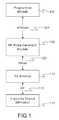
- FIG. 1depicts a high-level diagram of an example of a wireless neural stimulation system.
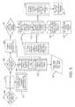
- FIG. 2depicts a detailed diagram of an example of the wireless neural stimulation system.
- FIG. 3is a flowchart showing an example of the operation of the wireless neural stimulator system.
- FIG. 4depicts a flow chart showing an example of the operation of the system when the current level at the electrodes is above the threshold limit.
- FIG. 5is a diagram showing examples of signals that may be used to detect an impedance mismatch.
- FIG. 6is a diagram showing examples of signals that may be employed during operation of the wireless neural stimulator system.
- FIG. 7is a flow chart showing a process for the user to control the implantable wireless neural stimulator through an external programmer in an open loop feedback system.
- FIG. 8is another example flow chart of a process for the user to control the wireless stimulator with limitations on the lower and upper limits of current amplitude.
- FIG. 9is yet another example flow chart of a process for the user to control the wireless neural stimulator through preprogrammed parameter settings.
- FIG. 10is still another example flow chart of a process for a low battery state for the RF pulse generator module.
- FIG. 11is yet another example flow chart of a process for a Manufacturer's Representative to program the implanted wireless neural stimulator.
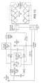
- FIG. 12is a circuit diagram showing an example of a wireless neural stimulator.
- FIG. 13is a circuit diagram of another example of a wireless neural stimulator.
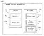
- FIG. 14is a block diagram showing an example of control and feedback functions of a wireless implantable neural stimulator.
- FIG. 15is a schematic showing an example of a wireless implantable neural stimulator with components to implement control and feedback functions.
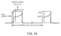
- FIG. 16shows an example of a pulse waveform seen at the power management circuitry of a wireless implantable neural stimulator.
- FIG. 17is a schematic of an example of a polarity routing switch network.
- FIGS. 18A and 18Brespectively show an example of a waveform generated by a rectifying circuit of a wireless neural stimulator and the corresponding spectrum.
- FIG. 19is a flow chart illustrating an example of operations of control and feedback functions of a wireless implantable neural stimulator.
- a neural stimulation systemmay be used to send electrical stimulation to targeted nerve tissue by using remote radio frequency (RF) energy with neither cables nor inductive coupling to power the passive implanted stimulator.
- the targeted nerve tissuesmay be, for example, in the spinal column including the spinothalamic tracts, dorsal horn, dorsal root ganglia, dorsal roots, dorsal column fibers, and peripheral nerves bundles leaving the dorsal column or brainstem, as well as any cranial nerves, abdominal, thoracic, or trigeminal ganglia nerves, nerve bundles of the cerebral cortex, deep brain and any sensory or motor nerves.
- RFradio frequency
- the neural stimulation systemmay include a controller module, such as an RF pulse generator module, and a passive implanted neural stimulator that contains one or more dipole antennas, one or more circuits, and one or more electrodes in contact with or in proximity to targeted neural tissue to facilitate stimulation.
- the RF pulse generator modulemay include an antenna and may be configured to transfer energy from the module antenna to the implanted antennas.
- the one or more circuits of the implanted neural stimulatormay be configured to generate electrical pulses suitable for neural stimulation using the transferred energy and to supply the electrical pulses to the electrodes so that the pulses are applied to the neural tissue.
- the one or more circuitsmay include wave conditioning circuitry that rectifies the received RF signal (for example, using a diode rectifier), transforms the RF energy to a low frequency signal suitable for the stimulation of neural tissue, and presents the resulting waveform to an electrode array.
- the one or more circuits of the implanted neural stimulatormay also include circuitry for communicating information back to the RF pulse generator module to facilitate a feedback control mechanism for stimulation parameter control.
- the implanted neural stimulatormay send to the RF pulse generator module a stimulus feedback signal that is indicative of parameters of the electrical pulses, and the RF pulse generator module may employ the stimulus feedback signal to adjust parameters of the signal sent to the neural stimulator.
- FIG. 1depicts a high-level diagram of an example of a neural stimulation system.
- the neural stimulation systemmay include four major components, namely, a programmer module 102 , a RF pulse generator module 106 , a transmit (TX) antenna 110 (for example, a patch antenna, slot antenna, or a dipole antenna), and an implanted wireless neural stimulator 114 .
- the programmer module 102may be a computer device, such as a smart phone, running a software application that supports a wireless connection 114 , such as Bluetooth®.
- the applicationcan enable the user to view the system status and diagnostics, change various parameters, increase/decrease the desired stimulus amplitude of the electrode pulses, and adjust feedback sensitivity of the RF pulse generator module 106 , among other functions.
- the RF pulse generator module 106may include communication electronics that support the wireless connection 104 , the stimulation circuitry, and the battery to power the generator electronics.
- the RF pulse generator module 106includes the TX antenna embedded into its packaging form factor while, in other implementations, the TX antenna is connected to the RF pulse generator module 106 through a wired connection 108 or a wireless connection (not shown).
- the TX antenna 110may be coupled directly to tissue to create an electric field that powers the implanted neural stimulator module 114 .
- the TX antenna 110communicates with the implanted neural stimulator module 114 through an RF interface. For instance, the TX antenna 110 radiates an RF transmission signal that is modulated and encoded by the RF pulse generator module 110 .
- the implanted wireless neural stimulator module 114contains one or more antennas, such as dipole antenna(s), to receive and transmit through RF interface 112 .
- the coupling mechanism between antenna 110 and the one or more antennas on the implanted neural stimulation module 114is electrical radiative coupling and not inductive coupling. In other words, the coupling is through an electric field rather than a magnetic field.
- the TX antenna 110can provide an input signal to the implanted neural stimulation module 114 .
- This input signalcontains energy and may contain information encoding stimulus waveforms to be applied at the electrodes of the implanted neural stimulator module 114 .
- the power level of this input signaldirectly determines an applied amplitude (for example, power, current, or voltage) of the one or more electrical pulses created using the electrical energy contained in the input signal.
- Within the implanted wireless neural stimulator 114are components for demodulating the RF transmission signal, and electrodes to deliver the stimulation to surrounding neuronal tissue.
- the RF pulse generator module 106can be implanted subcutaneously, or it can be worn external to the body. When external to the body, the RF generator module 106 can be incorporated into a belt or harness design to allow for electric radiative coupling through the skin and underlying tissue to transfer power and/or control parameters to the implanted neural stimulator module 114 , which can be a passive stimulator. In either event, receiver circuit(s) internal to the neural stimulator module 114 can capture the energy radiated by the TX antenna 110 and convert this energy to an electrical waveform. The receiver circuit(s) may further modify the waveform to create an electrical pulse suitable for the stimulation of neural tissue, and this pulse may be delivered to the tissue via electrode pads.
- the RF pulse generator module 106can remotely control the stimulus parameters (that is, the parameters of the electrical pulses applied to the neural tissue) and monitor feedback from the wireless neural stimulator module 114 based on RF signals received from the implanted wireless neural stimulator module 114 .
- a feedback detection algorithm implemented by the RF pulse generator module 106can monitor data sent wirelessly from the implanted wireless neural stimulator module 114 , including information about the energy that the implanted wireless neural stimulator module 114 is receiving from the RF pulse generator and information about the stimulus waveform being delivered to the electrode pads.
- the systemcan be tuned to provide the optimal amount of excitation or inhibition to the nerve fibers by electrical stimulation.
- a closed loop feedback control methodcan be used in which the output signals from the implanted wireless neural stimulator module 114 are monitored and used to determine the appropriate level of neural stimulation current for maintaining effective neuronal activation, or, in some cases, the patient can manually adjust the output signals in an open loop control method.
- FIG. 2depicts a detailed diagram of an example of the neural stimulation system.
- the programming module 102may comprise user input system 202 and communication subsystem 208 .
- the user input system 221may allow various parameter settings to be adjusted (in some cases, in an open loop fashion) by the user in the form of instruction sets.
- the communication subsystem 208may transmit these instruction sets (and other information) via the wireless connection 104 , such as Bluetooth or Wi-Fi, to the RF pulse generator module 106 , as well as receive data from module 106 .
- the programmer module 102which can be utilized for multiple users, such as a patient's control unit or clinician's programmer unit, can be used to send stimulation parameters to the RF pulse generator module 106 .
- the stimulation parameters that can be controlledmay include pulse amplitude, pulse frequency, and pulse width in the ranges shown in Table 1.
- pulserefers to the phase of the waveform that directly produces stimulation of the tissue; the parameters of the charge-balancing phase (described below) can similarly be controlled.
- the patient and/or the cliniciancan also optionally control overall duration and pattern of treatment.
- the implantable neural stimulator module 114 or RF pulse generator module 114may be initially programmed to meet the specific parameter settings for each individual patient during the initial implantation procedure. Because medical conditions or the body itself can change over time, the ability to re-adjust the parameter settings may be beneficial to ensure ongoing efficacy of the neural modulation therapy.
- the programmer module 102may be functionally a smart device and associated application.
- the smart device hardwaremay include a CPU 206 and be used as a vehicle to handle touchscreen input on a graphical user interface (GUI) 204 , for processing and storing data.
- GUIgraphical user interface
- the RF pulse generator module 106may be connected via wired connection 108 to an external TX antenna 110 .
- both the antenna and the RF pulse generatorare located subcutaneously (not shown).
- the signals sent by RF pulse generator module 106 to the implanted stimulator 114may include both power and parameter-setting attributes in regards to stimulus waveform, amplitude, pulse width, and frequency.
- the RF pulse generator module 106can also function as a wireless receiving unit that receives feedback signals from the implanted stimulator module 114 .
- the RF pulse generator module 106may contain microelectronics or other circuitry to handle the generation of the signals transmitted to the stimulator module 114 as well as handle feedback signals, such as those from the stimulator module 114 .
- the RF pulse generator module 106may comprise controller subsystem 214 , high-frequency oscillator 218 , RF amplifier 216 , a RF switch, and a feedback subsystem 212 .
- the controller subsystem 214may include a CPU 230 to handle data processing, a memory subsystem 228 such as a local memory, communication subsystem 234 to communicate with programmer module 102 (including receiving stimulation parameters from programmer module), pulse generator circuitry 236 , and digital/analog (D/A) converters 232 .
- a CPU 230to handle data processing
- a memory subsystem 228such as a local memory
- communication subsystem 234to communicate with programmer module 102 (including receiving stimulation parameters from programmer module)
- pulse generator circuitry 236including receiving stimulation parameters from programmer module
- D/A converters 232digital/analog
- the controller subsystem 214may be used by the patient and/or the clinician to control the stimulation parameter settings (for example, by controlling the parameters of the signal sent from RF pulse generator module 106 to neural stimulator module 114 ). These parameter settings can affect, for example, the power, current level, or shape of the one or more electrical pulses.
- the programming of the stimulation parameterscan be performed using the programming module 102 , as described above, to set the repetition rate, pulse width, amplitude, and waveform that will be transmitted by RF energy to the receive (RX) antenna 238 , typically a dipole antenna (although other types may be used), in the wireless implanted neural stimulator module 214 .
- the clinicianmay have the option of locking and/or hiding certain settings within the programmer interface, thus limiting the patient's ability to view or adjust certain parameters because adjustment of certain parameters may require detailed medical knowledge of neurophysiology, neuroanatomy, protocols for neural modulation, and safety limits of electrical stimulation.
- the controller subsystem 214may store received parameter settings in the local memory subsystem 228 , until the parameter settings are modified by new input data received from the programming module 102 .
- the CPU 206may use the parameters stored in the local memory to control the pulse generator circuitry 236 to generate a stimulus waveform that is modulated by a high frequency oscillator 218 in the range from 300 MHz to 8 GHz.
- the resulting RF signalmay then be amplified by RF amplifier 226 and then sent through an RF switch 223 to the TX antenna 110 to reach through depths of tissue to the RX antenna 238 .
- the RF signal sent by TX antenna 110may simply be a power transmission signal used by stimulator module 114 to generate electric pulses.
- a telemetry signalmay also be transmitted to the stimulator module 114 to send instructions about the various operations of the stimulator module 114 .
- the telemetry signalmay be sent by the modulation of the carrier signal (through the skin if external, or through other body tissues if the pulse generator module 106 is implanted subcutaneously).
- the telemetry signalis used to modulate the carrier signal (a high frequency signal) that is coupled onto the implanted antenna(s) 238 and does not interfere with the input received on the same lead to power the implant.
- the telemetry signal and powering signalare combined into one signal, where the RF telemetry signal is used to modulate the RF powering signal, and thus the implanted stimulator is powered directly by the received telemetry signal; separate subsystems in the stimulator harness the power contained in the signal and interpret the data content of the signal.
- the RF switch 223may be a multipurpose device such as a dual directional coupler, which passes the relatively high amplitude, extremely short duration RF pulse to the TX antenna 110 with minimal insertion loss while simultaneously providing two low-level outputs to feedback subsystem 212 ; one output delivers a forward power signal to the feedback subsystem 212 , where the forward power signal is an attenuated version of the RF pulse sent to the TX antenna 110 , and the other output delivers a reverse power signal to a different port of the feedback subsystem 212 , where reverse power is an attenuated version of the reflected RF energy from the TX Antenna 110 .
- a multipurpose devicesuch as a dual directional coupler, which passes the relatively high amplitude, extremely short duration RF pulse to the TX antenna 110 with minimal insertion loss while simultaneously providing two low-level outputs to feedback subsystem 212 ; one output delivers a forward power signal to the feedback subsystem 212 , where the forward power signal is an attenuated version of the RF
- the RF switch 223is set to send the forward power signal to feedback subsystem.
- the RF switch 223can change to a receiving mode in which the reflected RF energy and/or RF signals from the stimulator module 114 are received to be analyzed in the feedback subsystem 212 .
- the feedback subsystem 212 of the RF pulse generator module 106may include reception circuitry to receive and extract telemetry or other feedback signals from the stimulator 114 and/or reflected RF energy from the signal sent by TX antenna 110 .
- the feedback subsystemmay include an amplifier 226 , a filter 224 , a demodulator 222 , and an A/D converter 220 .
- the feedback subsystem 212receives the forward power signal and converts this high-frequency AC signal to a DC level that can be sampled and sent to the controller subsystem 214 . In this way the characteristics of the generated RF pulse can be compared to a reference signal within the controller subsystem 214 . If a disparity (error) exists in any parameter, the controller subsystem 214 can adjust the output to the RF pulse generator 106 . The nature of the adjustment can be, for example, proportional to the computed error.
- the controller subsystem 214can incorporate additional inputs and limits on its adjustment scheme such as the signal amplitude of the reverse power and any predetermined maximum or minimum values for various pulse parameters.
- the reverse power signalcan be used to detect fault conditions in the RF-power delivery system.
- TX antenna 110has perfectly matched impedance to the tissue that it contacts, the electromagnetic waves generated from the RF pulse generator 106 pass unimpeded from the TX antenna 110 into the body tissue.
- a large degree of variabilitymay exist in the body types of users, types of clothing worn, and positioning of the antenna 110 relative to the body surface.
- the impedance of the antenna 110depends on the relative permittivity of the underlying tissue and any intervening materials, and also depends on the overall separation distance of the antenna from the skin, in any given application there can be an impedance mismatch at the interface of the TX antenna 110 with the body surface. When such a mismatch occurs, the electromagnetic waves sent from the RF pulse generator 106 are partially reflected at this interface, and this reflected energy propagates backward through the antenna feed.
- the dual directional coupler RF switch 223may prevent the reflected RF energy propagating back into the amplifier 226 , and may attenuate this reflected RF signal and send the attenuated signal as the reverse power signal to the feedback subsystem 212 .
- the feedback subsystem 212can convert this high-frequency AC signal to a DC level that can be sampled and sent to the controller subsystem 214 .
- the controller subsystem 214can then calculate the ratio of the amplitude of the reverse power signal to the amplitude of the forward power signal. The ratio of the amplitude of reverse power signal to the amplitude level of forward power may indicate severity of the impedance mismatch.
- the controller subsystem 214can measure the reflected-power ratio in real time, and according to preset thresholds for this measurement, the controller subsystem 214 can modify the level of RF power generated by the RF pulse generator 106 .
- the course of actioncan be for the controller subsystem 214 to increase the amplitude of RF power sent to the TX antenna 110 , as would be needed to compensate for slightly non-optimum but acceptable TX antenna coupling to the body.
- the course of actioncan be to prevent operation of the RF pulse generator 106 and set a fault code to indicate that the TX antenna 110 has little or no coupling with the body.
- This type of reflected-power fault conditioncan also be generated by a poor or broken connection to the TX antenna. In either case, it may be desirable to stop RF transmission when the reflected-power ratio is above a defined threshold, because internally reflected power can lead to unwanted heating of internal components, and this fault condition means the system cannot deliver sufficient power to the implanted wireless neural stimulator and thus cannot deliver therapy to the user.
- the controller 242 of the stimulator 114may transmit informational signals, such as a telemetry signal, through the antenna 238 to communicate with the RF pulse generator module 106 during its receive cycle.
- the telemetry signal from the stimulator 114may be coupled to the modulated signal on the dipole antenna(s) 238 , during the on and off state of the transistor circuit to enable or disable a waveform that produces the corresponding RF bursts necessary to transmit to the external (or remotely implanted) pulse generator module 106 .
- the antenna(s) 238may be connected to electrodes 254 in contact with tissue to provide a return path for the transmitted signal.
- An A/D (not shown) convertercan be used to transfer stored data to a serialized pattern that can be transmitted on the pulse modulated signal from the internal antenna(s) 238 of the neural stimulator.
- a telemetry signal from the implanted wireless neural stimulator module 114may include stimulus parameters such as the power or the amplitude of the current that is delivered to the tissue from the electrodes.
- the feedback signalcan be transmitted to the RF pulse generator module 116 to indicate the strength of the stimulus at the nerve bundle by means of coupling the signal to the implanted RX antenna 238 , which radiates the telemetry signal to the external (or remotely implanted) RF pulse generator module 106 .
- the feedback signalcan include either or both an analog and digital telemetry pulse modulated carrier signal. Data such as stimulation pulse parameters and measured characteristics of stimulator performance can be stored in an internal memory device within the implanted neural stimulator 114 , and sent on the telemetry signal.
- the frequency of the carrier signalmay be in the range of at 300 MHz to 8 GHz.
- the telemetry signalcan be down modulated using demodulator 222 and digitized by being processed through an analog to digital (A/D) converter 220 .
- the digital telemetry signalmay then be routed to a CPU 230 with embedded code, with the option to reprogram, to translate the signal into a corresponding current measurement in the tissue based on the amplitude of the received signal.
- the CPU 230 of the controller subsystem 214can compare the reported stimulus parameters to those held in local memory 228 to verify the stimulator(s) 114 delivered the specified stimuli to tissue.
- the power level from the RF pulse generator module 106can be increased so that the implanted neural stimulator 114 will have more available power for stimulation.
- the implanted neural stimulator 114can generate telemetry data in real time, for example, at a rate of 8 kbits per second. All feedback data received from the implanted lead module 114 can be logged against time and sampled to be stored for retrieval to a remote monitoring system accessible by the health care professional for trending and statistical correlations.
- the sequence of remotely programmable RF signals received by the internal antenna(s) 238may be conditioned into waveforms that are controlled within the implantable stimulator 114 by the control subsystem 242 and routed to the appropriate electrodes 254 that are placed in proximity to the tissue to be stimulated.
- the RF signal transmitted from the RF pulse generator module 106may be received by RX antenna 238 and processed by circuitry, such as waveform conditioning circuitry 240 , within the implanted wireless neural stimulator module 114 to be converted into electrical pulses applied to the electrodes 254 through electrode interface 252 .
- the implanted stimulator 114contains between two to sixteen electrodes 254 .
- the waveform conditioning circuitry 240may include a rectifier 244 , which rectifies the signal received by the RX antenna 238 .
- the rectified signalmay be fed to the controller 242 for receiving encoded instructions from the RF pulse generator module 106 .
- the rectifier signalmay also be fed to a charge balance component 246 that is configured to create one or more electrical pulses based such that the one or more electrical pulses result in a substantially zero net charge at the one or more electrodes (that is, the pulses are charge balanced).
- the charge-balanced pulsesare passed through the current limiter 248 to the electrode interface 252 , which applies the pulses to the electrodes 254 as appropriate.
- the current limiter 248insures the current level of the pulses applied to the electrodes 254 is not above a threshold current level.
- an amplitude (for example, current level, voltage level, or power level) of the received RF pulsedirectly determines the amplitude of the stimulus.
- it is the charge per phase that should be limited for safetywhere the charge delivered by a stimulus phase is the integral of the current).
- the limiter 248acts as a charge limiter that limits a characteristic (for example, current or duration) of the electrical pulses so that the charge per phase remains below a threshold level (typically, a safe-charge limit).
- the current limiter 248can automatically limit or “clip” the stimulus phase to maintain the total charge of the phase within the safety limit.
- the current limiter 248may be a passive current limiting component that cuts the signal to the electrodes 254 once the safe current limit (the threshold current level) is reached. Alternatively, or additionally, the current limiter 248 may communicate with the electrode interface 252 to turn off all electrodes 254 to prevent tissue damaging current levels.
- a clipping eventmay trigger a current limiter feedback control mode.
- the action of clippingmay cause the controller to send a threshold power data signal to the pulse generator 106 .
- the feedback subsystem 212detects the threshold power signal and demodulates the signal into data that is communicated to the controller subsystem 214 .
- the controller subsystem 214 algorithmsmay act on this current-limiting condition by specifically reducing the RF power generated by the RF pulse generator, or cutting the power completely. In this way, the pulse generator 106 can reduce the RF power delivered to the body if the implanted wireless neural stimulator 114 reports it is receiving excess RF power.
- the controller 250 of the stimulator 205may communicate with the electrode interface 252 to control various aspects of the electrode setup and pulses applied to the electrodes 254 .
- the electrode interface 252may act as a multiplex and control the polarity and switching of each of the electrodes 254 .
- the wireless stimulator 106has multiple electrodes 254 in contact with tissue, and for a given stimulus the RF pulse generator module 106 can arbitrarily assign one or more electrodes to 1) act as a stimulating electrode, 2) act as a return electrode, or 3) be inactive by communication of assignment sent wirelessly with the parameter instructions, which the controller 250 uses to set electrode interface 252 as appropriate. It may be physiologically advantageous to assign, for example, one or two electrodes as stimulating electrodes and to assign all remaining electrodes as return electrodes.
- the controller 250may control the electrode interface 252 to divide the current arbitrarily (or according to instructions from pulse generator module 106 ) among the designated stimulating electrodes.
- This control over electrode assignment and current controlcan be advantageous because in practice the electrodes 254 may be spatially distributed along various neural structures, and through strategic selection of the stimulating electrode location and the proportion of current specified for each location, the aggregate current distribution in tissue can be modified to selectively activate specific neural targets. This strategy of current steering can improve the therapeutic effect for the patient.
- the time course of stimulimay be arbitrarily manipulated.
- a given stimulus waveformmay be initiated at a time T_start and terminated at a time T_final, and this time course may be synchronized across all stimulating and return electrodes; further, the frequency of repetition of this stimulus cycle may be synchronous for all the electrodes.
- controller 250on its own or in response to instructions from pulse generator 106 , can control electrode interface 252 to designate one or more subsets of electrodes to deliver stimulus waveforms with non-synchronous start and stop times, and the frequency of repetition of each stimulus cycle can be arbitrarily and independently specified.
- a stimulator having eight electrodesmay be configured to have a subset of five electrodes, called set A, and a subset of three electrodes, called set B.
- Set Amight be configured to use two of its electrodes as stimulating electrodes, with the remainder being return electrodes.
- Set Bmight be configured to have just one stimulating electrode.
- the controller 250could then specify that set A deliver a stimulus phase with 3 mA current for a duration of 200 us followed by a 400 us charge-balancing phase. This stimulus cycle could be specified to repeat at a rate of 60 cycles per second. Then, for set B, the controller 250 could specify a stimulus phase with 1 mA current for duration of 500 us followed by a 800 us charge-balancing phase.
- the repetition rate for the set-B stimulus cyclecan be set independently of set A, say for example it could be specified at 25 cycles per second. Or, if the controller 250 was configured to match the repetition rate for set B to that of set A, for such a case the controller 250 can specify the relative start times of the stimulus cycles to be coincident in time or to be arbitrarily offset from one another by some delay interval.
- the controller 250can arbitrarily shape the stimulus waveform amplitude, and may do so in response to instructions from pulse generator 106 .
- the stimulus phasemay be delivered by a constant-current source or a constant-voltage source, and this type of control may generate characteristic waveforms that are static, e.g. a constant-current source generates a characteristic rectangular pulse in which the current waveform has a very steep rise, a constant amplitude for the duration of the stimulus, and then a very steep return to baseline.
- the controller 250can increase or decrease the level of current at any time during the stimulus phase and/or during the charge-balancing phase.
- the controller 250can deliver arbitrarily shaped stimulus waveforms such as a triangular pulse, sinusoidal pulse, or Gaussian pulse for example.
- the charge-balancing phasecan be arbitrarily amplitude-shaped, and similarly a leading anodic pulse (prior to the stimulus phase) may also be amplitude-shaped.
- the stimulator 114may include a charge-balancing component 246 .
- pulsesshould be charge balanced by having the amount of cathodic current should equal the amount of anodic current, which is typically called biphasic stimulation.
- Charge densityis the amount of current times the duration it is applied, and is typically expressed in the units uC/cm 2 .
- no net chargeshould appear at the electrode-electrolyte interface, and it is generally acceptable to have a charge density less than 30 uC/cm 2 .
- Biphasic stimulating current pulsesensure that no net charge appears at the electrode after each stimulation cycle and the electrochemical processes are balanced to prevent net dc currents.
- Neural stimulator 114may be designed to ensure that the resulting stimulus waveform has a net zero charge. Charge balanced stimuli are thought to have minimal damaging effects on tissue by reducing or eliminating electrochemical reaction products created at the electrode-tissue interface.
- a stimulus pulsemay have a negative-voltage or current, called the cathodic phase of the waveform.
- Stimulating electrodesmay have both cathodic and anodic phases at different times during the stimulus cycle.
- An electrode that delivers a negative current with sufficient amplitude to stimulate adjacent neural tissueis called a “stimulating electrode.”
- the stimulating electrodeacts as a current sink.
- One or more additional electrodesact as a current source and these electrodes are called “return electrodes.” Return electrodes are placed elsewhere in the tissue at some distance from the stimulating electrodes.
- the return electrodeWhen a typical negative stimulus phase is delivered to tissue at the stimulating electrode, the return electrode has a positive stimulus phase.
- the polarities of each electrodeare reversed.
- the charge balance component 246uses a blocking capacitor(s) placed electrically in series with the stimulating electrodes and body tissue, between the point of stimulus generation within the stimulator circuitry and the point of stimulus delivery to tissue.
- a resistor-capacitor (RC) networkmay be formed.
- one charge-balance capacitor(s)may be used for each electrode or a centralized capacitor(s) may be used within the stimulator circuitry prior to the point of electrode selection.
- the RC networkcan block direct current (DC), however it can also prevent low-frequency alternating current (AC) from passing to the tissue.
- the frequency below which the series RC network essentially blocks signalsis commonly referred to as the cutoff frequency, and in one embodiment the design of the stimulator system may ensure the cutoff frequency is not above the fundamental frequency of the stimulus waveform.
- the wireless stimulatormay have a charge-balance capacitor with a value chosen according to the measured series resistance of the electrodes and the tissue environment in which the stimulator is implanted. By selecting a specific capacitance value the cutoff frequency of the RC network in this embodiment is at or below the fundamental frequency of the stimulus pulse.
- the cutoff frequencymay be chosen to be at or above the fundamental frequency of the stimulus, and in this scenario the stimulus waveform created prior to the charge-balance capacitor, called the drive waveform, may be designed to be non-stationary, where the envelope of the drive waveform is varied during the duration of the drive pulse.
- the initial amplitude of the drive waveformis set at an initial amplitude Vi, and the amplitude is increased during the duration of the pulse until it reaches a final value k*Vi.
- the shape of the stimulus waveform passed through the charge-balance capacitoris also modified. The shape of the stimulus waveform may be modified in this fashion to create a physiologically advantageous stimulus.
- the wireless neural stimulator module 114may create a drive-waveform envelope that follows the envelope of the RF pulse received by the receiving dipole antenna(s) 238 .
- the RF pulse generator module 106can directly control the envelope of the drive waveform within the wireless neural stimulator 114 , and thus no energy storage may be required inside the stimulator itself.
- the stimulator circuitrymay modify the envelope of the drive waveform or may pass it directly to the charge-balance capacitor and/or electrode-selection stage.
- the implanted neural stimulator 114may deliver a single-phase drive waveform to the charge balance capacitor or it may deliver multiphase drive waveforms.
- a single-phase drive waveformfor example, a negative-going rectangular pulse
- this pulsecomprises the physiological stimulus phase
- the charge-balance capacitoris polarized (charged) during this phase.
- the charge balancing functionis performed solely by the passive discharge of the charge-balance capacitor, where is dissipates its charge through the tissue in an opposite polarity relative to the preceding stimulus.
- a resistor within the stimulatorfacilitates the discharge of the charge-balance capacitor.
- the capacitormay allow virtually complete discharge prior to the onset of the subsequent stimulus pulse.
- the wireless stimulatormay perform internal switching to pass negative-going or positive-going pulses (phases) to the charge-balance capacitor.
- phasespositive-going pulses
- These pulsesmay be delivered in any sequence and with varying amplitudes and waveform shapes to achieve a desired physiological effect.
- the stimulus phasemay be followed by an actively driven charge-balancing phase, and/or the stimulus phase may be preceded by an opposite phase.
- Preceding the stimulus with an opposite-polarity phasefor example, can have the advantage of reducing the amplitude of the stimulus phase required to excite tissue.
- the amplitude and timing of stimulus and charge-balancing phasesis controlled by the amplitude and timing of RF pulses from the RF pulse generator module 106 , and in others this control may be administered internally by circuitry onboard the wireless stimulator 114 , such as controller 250 . In the case of onboard control, the amplitude and timing may be specified or modified by data commands delivered from the pulse generator module 106 .
- FIG. 3is a flowchart showing an example of an operation of the neural stimulator system.
- the wireless neural stimulator 114is implanted in proximity to nerve bundles and is coupled to the electric field produced by the TX antenna 110 . That is, the pulse generator module 106 and the TX antenna 110 are positioned in such a way (for example, in proximity to the patient) that the TX antenna 110 is electrically radiatively coupled with the implanted RX antenna 238 of the neural stimulator 114 .
- both the antenna 110 and the RF pulse generator 106are located subcutaneously. In other implementations, the antenna 110 and the RF pulse generator 106 are located external to the patient's body. In this case, the TX antenna 110 may be coupled directly to the patient's skin.
- Energy from the RF pulse generatoris radiated to the implanted wireless neural stimulator 114 from the antenna 110 through tissue, as shown in block 304 .
- the energy radiatedmay be controlled by the Patient/Clinician Parameter inputs in block 301 .
- the parameter settingscan be adjusted in an open loop fashion by the patient or clinician, who would adjust the parameter inputs in block 301 to the system.
- the wireless implanted stimulator 114uses the received energy to generate electrical pulses to be applied to the neural tissue through the electrodes 238 .
- the stimulator 114may contain circuitry that rectifies the received RF energy and conditions the waveform to charge balance the energy delivered to the electrodes to stimulate the targeted nerves or tissues, as shown in block 306 .
- the implanted stimulator 114communicates with the pulse generator 106 by using antenna 238 to send a telemetry signal, as shown in block 308 .
- the telemetry signalmay contain information about parameters of the electrical pulses applied to the electrodes, such as the impedance of the electrodes, whether the safe current limit has been reached, or the amplitude of the current that is presented to the tissue from the electrodes.
- the RF pulse generator 106detects amplifies, filters and modulates the received telemetry signal using amplifier 226 , filter 224 , and demodulator 222 , respectively.
- the A/D converter 230then digitizes the resulting analog signal, as shown in 312 .
- the digital telemetry signalis routed to CPU 230 , which determines whether the parameters of the signal sent to the stimulator 114 need to be adjusted based on the digital telemetry signal. For instance, in block 314 , the CPU 230 compares the information of the digital signal to a look-up table, which may indicate an appropriate change in stimulation parameters. The indicated change may be, for example, a change in the current level of the pulses applied to the electrodes. As a result, the CPU may change the output power of the signal sent to stimulator 114 so as to adjust the current applied by the electrodes 254 , as shown in block 316 .
- the CPU 230may adjust parameters of the signal sent to the stimulator 114 every cycle to match the desired current amplitude setting programmed by the patient, as shown in block 318 .
- the status of the stimulator systemmay be sampled in real time at a rate of 8 kbits per second of telemetry data. All feedback data received from the stimulator 114 can be maintained against time and sampled per minute to be stored for download or upload to a remote monitoring system accessible by the health care professional for trending and statistical correlations in block 318 .
- the stimulator system operationmay be reduced to just the functional elements shown in blocks 302 , 304 , 306 , and 308 , and the patient uses their judgment to adjust parameter settings rather than the closed looped feedback from the implanted device.
- FIG. 4depicts a flow chart showing an example of an operation of the system when the current level at the electrodes 254 is above a threshold limit.
- the implanted wireless neural stimulator 114may receive an input power signal with a current level above an established safe current limit, as shown in block 402 .
- the current limiter 248may determine the current is above an established tissue-safe limit of amperes, as shown in block 404 . If the current limiter senses that the current is above the threshold, it may stop the high-power signal from damaging surrounding tissue in contact with the electrodes as shown in block 406 , the operations of which are as described above in association with FIG. 2 .
- a capacitormay store excess power, as shown in block 408 .
- the controller 250may use the excess power available to transmit a small 2-bit data burst back to the RF pulse generator 106 , as shown in block 410 .
- the 2-bit data burstmay be transmitted through the implanted wireless neural stimulator's antenna(s) 238 during the RF pulse generator's receive cycle, as shown in block 412 .
- the RF pulse generator antenna 110may receive the 2-bit data burst during its receive cycle, as shown in block 414 , at a rate of 8 kbps, and may relay the data burst back to the RF pulse generator's feedback subsystem 212 which is monitoring all reverse power, as shown in block 416 .
- the CPU 230may analyze signals from feedback subsystem 202 , as shown in block 418 and if there is no data burst present, no changes may be made to the stimulation parameters, as shown in block 420 . If the data burst is present in the analysis, the CPU 230 can cut all transmission power for one cycle, as shown in block 422 .
- the RF pulse generator 106may push a “proximity power danger” notification to the application on the programmer module 102 , as shown in block 424 .
- This proximity danger notificationoccurs because the RF pulse generator has ceased its transmission of power. This notification means an unauthorized form of energy is powering the implant above safe levels.
- the applicationmay alert the user of the danger and that the user should leave the immediate area to resume neural modulation therapy, as shown in block 426 . If after one cycle the data burst has stopped, the RF pulse generator 106 may slowly ramp up the transmission power in increments, for example from 5% to 75% of previous current amplitude levels, as shown in block 428 .
- the RF pulse generator 106may notify the application of its progress and the application may notify the user that there was an unsafe power level and the system is ramping back up, as shown in block 430 .
- FIG. 5is a diagram showing examples of signals that may be used to detect an impedance mismatch.
- a forward power signal and a reverse power signalmay be used to detect an impedance mismatch.
- a RF pulse 502 generated by the RF pulse generatormay pass through a device such as a dual directional coupler to the TX antenna 110 .
- the TX antenna 110then radiates the RF signal into the body, where the energy is received by the implanted wireless neural stimulator 114 and converted into a tissue-stimulating pulse.
- the couplerpasses an attenuated version of this RF signal, forward power 510 , to feedback subsystem 212 .
- the feedback subsystem 212demodulates the AC signal and computes the amplitude of the forward RF power, and this data is passed to controller subsystem 214 .
- the dual directional coupler(or similar component) also receives RF energy reflected back from the TX antenna 110 and passes an attenuated version of this RF signal, reverse power 512 , to feedback subsystem 212 .
- the feedback subsystem 212demodulates the AC signal and computes the amplitude of the reflected RF power, and this data is passed to controller subsystem 214 .
- the TX antenna 110may be perfectly impedance-matched to the body so that the RF energy passes unimpeded across the interface of the TX antenna 110 to the body, and no RF energy is reflected at the interface.
- the reverse power 512may have close to zero amplitude as shown by signal 504 , and the ratio of reverse power 512 to forward power 510 is zero. In this circumstance, no error condition exists, and the controller 214 sets a system message that operation is optimal.
- the impedance match of the TX antenna 204 to the bodymay not be optimal, and some energy of the RF pulse 502 is reflected from the interface of the TX antenna 110 and the body. This can occur for example if the TX antenna 110 is held somewhat away from the skin by a piece of clothing. This non-optimal antenna coupling causes a small portion of the forward RF energy to be reflected at the interface, and this is depicted as signal 506 . In this case, the ratio of reverse power 512 to forward power 510 is small, but a small ratio implies that most of the RF energy is still radiated from the TX antenna 110 , so this condition is acceptable within the control algorithm.
- This determination of acceptable reflection ratiomay be made within controller subsystem 214 based upon a programmed threshold, and the controller subsystem 214 may generate a low-priority alert to be sent to the user interface.
- the controller subsystem 214 sensing the condition of a small reflection ratiomay moderately increase the amplitude of the RF pulse 502 to compensate for the moderate loss of forward energy transfer to the implanted wireless neural stimulator 114 .
- the TX antenna 110During daily operational use, the TX antenna 110 might be accidentally removed from the body entirely, in which case the TX antenna will have very poor coupling to the body (if any). In this or other circumstances, a relatively high proportion of the RF pulse energy is reflected as signal 508 from the TX antenna 110 and fed backward into the RF-powering system. Similarly, this phenomenon can occur if the connection to the TX antenna is physically broken, in which case virtually 100% of the RF energy is reflected backward from the point of the break. In such cases, the ratio of reverse power 512 to forward power 510 is very high, and the controller subsystem 214 will determine the ratio has exceeded the threshold of acceptance. In this case, the controller subsystem 214 may prevent any further RF pulses from being generated. The shutdown of the RF pulse generator module 106 may be reported to the user interface to inform the user that stimulation therapy cannot be delivered.
- FIG. 6is a diagram showing examples of signals that may be employed during operation of the neural stimulator system.
- the amplitude of the RF pulse 602 received by the implanted wireless neural stimulator 114can directly control the amplitude of the stimulus 630 delivered to tissue.
- the duration of the RF pulse 608corresponds to the specified pulse width of the stimulus 630 .
- the RF pulse generator module 106sends an RF pulse waveform 602 via TX antenna 110 into the body, and RF pulse waveform 608 may represent the corresponding RF pulse received by implanted wireless neural stimulator 114 .
- the received powerhas an amplitude suitable for generating a safe stimulus pulse 630 .
- the stimulus pulse 630is below the safety threshold 626 , and no error condition exists.
- the attenuation between the TX antenna 110 and the implanted wireless neural stimulator 114has been unexpectedly reduced, for example due to the user repositioning the TX antenna 110 . This reduced attenuation can lead to increased amplitude in the RF pulse waveform 612 being received at the neural stimulator 114 .
- the RF pulse 602is generated with the same amplitude as before, the improved RF coupling between the TX antenna 110 and the implanted wireless neural stimulator 114 can cause the received RF pulse 612 to be larger in amplitude.
- Implanted wireless neural stimulator 114 in this situationmay generate a larger stimulus 632 in response to the increase in received RF pulse 612 .
- the received power 612is capable of generating a stimulus 632 that exceeds the prudent safety limit for tissue.
- the current limiter feedback control modecan operate to clip the waveform of the stimulus pulse 632 such that the stimulus delivered is held within the predetermined safety limit 626 .
- the clipping event 628may be communicated through the feedback subsystem 212 as described above, and subsequently controller subsystem 214 can reduce the amplitude specified for the RF pulse.
- the current limiter feedback control modemay operate to reduce the RF power delivered to the body if the implanted wireless neural stimulator 114 receives excess RF power.
- the RF pulse waveform 606depicts a higher amplitude RF pulse generated as a result of user input to the user interface.
- the RF pulse 620 received by the implanted wireless neural stimulator 14is increased in amplitude, and similarly current limiter feedback mode operates to prevent stimulus 636 from exceeding safety limit 626 .
- this clipping event 628may be communicated through the feedback subsystem 212 , and subsequently controller subsystem 214 may reduce the amplitude of the RF pulse, thus overriding the user input.
- the reduced RF pulse 604can produce correspondingly smaller amplitudes of the received waveforms 616 , and clipping of the stimulus current may no longer be required to keep the current within the safety limit.
- the current limiter feedbackmay reduce the RF power delivered to the body if the implanted wireless neural stimulator 114 reports it is receiving excess RF power.
- FIG. 7is a flow chart showing a process for the user to control the implantable wireless neural stimulator through the programmer in an open loop feedback system.
- the userhas a wireless neural stimulator implanted in their body, the RF pulse generator 106 sends the stimulating pulse power wirelessly to the stimulator 114 , and an application on the programmer module 102 (for example, a smart device) is communicating with the RF pulse generator 106 .
- an application on the programmer module 102for example, a smart device
- the usermay open the application, as shown in block 704 .
- the applicationcan use Bluetooth protocols built into the smart device to interrogate the pulse generator, as shown in block 706 .
- the RF pulse generator 106may authenticate the identity of the smart device and serialized patient assigned secure iteration of the application, as shown in block 708 .
- the authentication processmay utilize a unique key to the patient specific RF pulse generator serial number.
- the applicationcan be customized with the patient specific unique key through the Manufacturer Representative who has programmed the initial patient settings for the stimulation system, as shown in block 720 . If the RF pulse generator rejects the authentication it may inform the application that the code is invalid, as shown in block 718 and needs the authentication provided by the authorized individual with security clearance from the device manufacturer, known as the “Manufacturer's Representative,” as shown in block 722 . In an implementation, only the Manufacturer's Representative can have access to the security code needed to change the application's stored RF pulse generator unique ID.
- the pulse generator module 106sends back all of the data that has been logged since the last sync, as shown in block 710 .
- the applicationmay then register the most current information and transmit the information to a 3rd party in a secure fashion, as shown in 712 .
- the applicationmay maintain a database that logs all system diagnostic results and values, the changes in settings by the user and the feedback system, and the global runtime history, as shown in block 714 .
- the applicationmay then display relevant data to the user, as shown in block 716 ; including the battery capacity, current program parameter, running time, pulse width, frequency, amplitude, and the status of the feedback system.
- FIG. 8is another example flow chart of a process for the user to control the wireless stimulator with limitations on the lower and upper limits of current amplitude.
- the userwants to change the amplitude of the stimulation signal, as shown in block 802 .
- the usermay open the application, as show in block 704 and the application may go through the process described in FIG. 7 to communicate with the RF pulse generator, authenticate successfully, and display the current status to the user, as shown in block 804 .
- the applicationdisplays the stimulation amplitude as the most prevalent changeable interface option and displays two arrows with which the user can adjust the current amplitude.
- the usermay make a decision based on their need for more or less stimulation in accordance with their pain levels, as shown in block 806 .
- the usermay press the up arrow on the application screen, as shown in block 808 .
- the applicationcan include safety maximum limiting algorithms, so if a request to increase current amplitude is recognized by the application as exceeding the preset safety maximum, as shown in block 810 , then the application will display an error message, as shown in block 812 and will not communicate with the RF pulse generator module 106 . If the user presses the up arrow, as shown in block 808 and the current amplitude request does not exceed the current amplitude maximum allowable value, then the application will send instructions to the RF pulse generator module 106 to increase amplitude, as shown in block 814 .
- the RF pulse generator module 106may then attempt to increase the current amplitude of stimulation, as shown in block 816 . If the RF pulse generator is successful at increasing the current amplitude, the RF pulse generator module 106 may perform a short vibration to physically confirm with the user that the amplitude is increased, as shown in block 818 . The RF pulse generator module 106 can also send back confirmation of increased amplitude to the application, as shown in block 820 , and then the application may display the updated current amplitude level, as shown in block 822 .
- the usercan press the down arrow on the application, as shown in block 828 . If the current amplitude level is already at zero, the application recognizes that the current amplitude cannot be decreased any further, as shown in block 830 and displays an error message to the user without communicating any data to the RF pulse generator, as shown in block 832 . If the current amplitude level is not at zero, the application can send instructions to the RF pulse generator module 106 to decrease current amplitude level accordingly, as shown in block 834 .
- the RF pulse generatormay then attempt to decrease current amplitude level of stimulation RF pulse generator module 106 and, if successful, the RF pulse generator module 106 may perform a short vibration to physically confirm to the user that the current amplitude level has been decreased, as shown in block 842 .
- the RF pulse generator module 106can send back confirmation of the decreased current amplitude level to the application, as shown in block 838 .
- the applicationthen may display the updated current amplitude level, as indicated by block 840 . If the current amplitude level decrease or increase fails, the RF pulse generator module 106 can perform a series of short vibrations to alert user, and send an error message to the application, as shown in block 824 .
- the applicationreceives the error and may display the data for the user's benefit, as shown in block 826 .
- FIG. 9is yet another example flow chart of a process for the user to control the wireless neural stimulator 114 through preprogrammed parameter settings.
- the userwants to change the parameter program, as indicated by block 902 .
- the Manufacturer's Representativemay determine and provide the patient/user RF pulse generator with preset programs that have different stimulation parameters that will be used to treat the user. The user will then able to switch between the various parameter programs as needed.
- the usercan open the application on their smart device, as indicated by block 704 , which first follows the process described in FIG.
- a tablecan be displayed to the user, as shown in block 908 and each row displays a program's codename and lists its basic parameter settings, as shown in block 910 , which includes but is not limited to: pulse width, frequency, cycle timing, pulse shape, duration, feedback sensitivity, as shown in block 912 .
- the usermay then select the row containing the desired parameter preset program to be used, as shown in block 912 .
- the applicationcan send instructions to the RF pulse generator module 106 to change the parameter settings, as shown in block 916 .
- the RF pulse generator module 106may attempt to change the parameter settings 154 . If the parameter settings are successfully changed, the RF pulse generator module 106 can perform a unique vibration pattern to physically confirm with the user that the parameter settings were changed, as shown in block 920 .
- the RF pulse generator module 106can send back confirmation to the application that the parameter change has been successful, as shown in block 922 , and the application may display the updated current program, as shown in block 924 . If the parameter program change has failed, the RF pulse generator module 106 may perform a series of short vibrations to alert the user, and send an error message to the application, as shown in block 926 , which receives the error and may display to the user, as shown in block 928 .
- FIG. 10is still another example flow chart of a process for a low battery state for the RF pulse generator module 106 .
- the RF pulse generator module's remaining battery power levelis recognized as low, as shown in block 1002 .
- the RF pulse generator module 106regularly interrogates the power supply battery subsystem 210 about the current power and the RF pulse generator microprocessor asks the battery if its remaining power is below threshold, as shown in block 1004 . If the battery's remaining power is above the threshold, the RF pulse generator module 106 may store the current battery status to be sent to the application during the next sync, as shown in block 1006 .
- the RF pulse generator module 106may push a low-battery notification to the application, as shown in block 1008 .
- the RF pulse generator module 106may always perform one sequence of short vibrations to alert the user of an issue and send the application a notification, as shown in block 1010 . If there continues to be no confirmation of the application receiving the notification then the RF pulse generator can continue to perform short vibration pulses to notify user, as shown in block 1010 . If the application successfully receives the notification, it may display the notification and may need user acknowledgement, as shown in block 1012 .
- the applicationinforms the RF pulse generator module 106 about lack of human acknowledgement, as shown in block 1014 , and the RF pulse generator module 106 may begin to perform the vibration pulses to notify the user, as shown in block 1010 .
- the applicationmay display a passive notification to switch the battery, as shown in block 1016 . If a predetermined amount of time passes, such as five minutes for example, without the battery being switched, the application can inform the RF pulse generator module 106 of the lack of human acknowledgement, as shown in block 1014 and the RF pulse generator module 106 may perform vibrations, as shown in block 1010 .
- the RF pulse generator module 106reboots and interrogates the battery to assess power remaining, as shown in block 1018 . If the battery's power remaining is below threshold, the cycle may begin again with the RF pulse generator module 106 pushing a notification to the application, as shown in block 1008 . If the battery's power remaining is above threshold the RF pulse generator module 106 may push a successful battery-change notification to the application, as shown in block 1020 . The application may then communicate with the RF pulse generator module 106 and displays current system status, as shown in block 1022 .
- FIG. 11is yet another example flow chart of a process for a Manufacturer's Representative to program the implanted wireless neural stimulator.
- a userwants the Manufacturer's Representative to set individual parameter programs from a remote location different than where the user is, for the user to use as needed, as shown in block 1102 .
- the Manufacturer's Representativecan gain access to the user's set parameter programs through a secure web based service.
- the Manufacturer's Representativecan securely log into the manufacturer's web service on a device connected to the Internet, as shown in block 1104 . If the Manufacturer's Representative is registering the user for the first time in their care they enter in the patient's basic information, the RF pulse generator's unique ID and the programming application's unique ID, as shown in block 1106 .
- the Manufacturer's Representativeaccesses the specific user's profile, as shown in block 1108 .
- the Manufacturer's Representativeis able to view the current allotted list of parameter programs for the specific user, as shown in block 1110 . This list may contain previous active and retired parameter preset programs, as shown in block 1112 .
- the Manufacturer's Representativeis able to activate/deactivate preset parameter programs by checking the box next to the appropriate row in the table displayed, as shown in block 1114 .
- the Manufacturer's Representativemay then submit and save the allotted new preset parameter programs, as shown in block 1116 .
- the user's programmer applicationmay receive the new preset parameter programs at the next sync with the manufacturer's database.
- FIG. 12is a circuit diagram showing an example of a wireless neural stimulator, such as stimulator 114 .
- This examplecontains paired electrodes, comprising cathode electrode(s) 1208 and anode electrode(s) 1210 , as shown. When energized, the charged electrodes create a volume conduction field of current density within the tissue.
- the wireless energyis received through a dipole antenna(s) 238 . At least four diodes are connected together to form a full wave bridge rectifier 1202 attached to the dipole antenna(s) 238 .
- Each diodeuses a junction potential to prevent the flow of negative electrical current, from cathode to anode, from passing through the device when said current does not exceed the reverse threshold.
- the natural inefficiency of the lossy materialmay lead to a low threshold voltage.
- a zero biased diode rectifierresults in a low output impedance for the device.
- a resistor 1204 and a smoothing capacitor 1206are placed across the output nodes of the bridge rectifier to discharge the electrodes to the ground of the bridge anode.
- the rectification bridge 1202includes two branches of diode pairs connecting an anode-to-anode and then cathode to cathode.
- the electrodes 1208 and 1210are connected to the output of the charge balancing circuit 246 .
- FIG. 13is a circuit diagram of another example of a wireless neural stimulator, such as stimulator 114 .
- the example shown in FIG. 13includes multiple electrode control and may employ full closed loop control.
- the stimulatorincludes an electrode array 254 in which the polarity of the electrodes can be assigned as cathodic or anodic, and for which the electrodes can be alternatively not powered with any energy.
- the charged electrodesWhen energized, create a volume conduction field of current density within the tissue.
- the wireless energyis received by the device through the dipole antenna(s) 238 .
- the electrode array 254is controlled through an on-board controller circuit 242 that sends the appropriate bit information to the electrode interface 252 in order to set the polarity of each electrode in the array, as well as power to each individual electrode. The lack of power to a specific electrode would set that electrode in a functional OFF position.
- the amount of current sent to each electrodeis also controlled through the controller 242 .
- the controller current, polarity and power state parameter data, shown as the controller output,is be sent back to the antenna(s) 238 for telemetry transmission back to the pulse generator module 106 .
- the controller 242also includes the functionality of current monitoring and sets a bit register counter so that the status of total current drawn can be sent back to the pulse generator module 106 .
- At least four diodescan be connected together to form a full wave bridge rectifier 302 attached to the dipole antenna(s) 238 .
- Each diodeup to 100 micrometers in length, uses a junction potential to prevent the flow of negative electrical current, from cathode to anode, from passing through the device when said current does not exceed the reverse threshold.
- the natural inefficiency of the lossy materialmay lead to a low threshold voltage.
- a zero biased diode rectifierresults in a low output impedance for the device.
- a resistor 1204 and a smoothing capacitor 1206are placed across the output nodes of the bridge rectifier to discharge the electrodes to the ground of the bridge anode.
- the rectification bridge 1202may include two branches of diode pairs connecting an anode-to-anode and then cathode to cathode.
- the electrode polarity outputs, both cathode 1208 and anode 1210are connected to the outputs formed by the bridge connection.
- Charge balancing circuitry 246 and current limiting circuitry 248are placed in series with the outputs.
- FIG. 14is a block diagram showing an example of control functions 1405 and feedback functions 1430 of a wireless implantable neural stimulator 1400 , such as the ones described above or further below.
- An example implementation of the implantable neural stimulator 1400may be implanted lead module 114 , as discussed above in association with FIG. 2 .
- Control functions 1405include functions 1410 for polarity switching of the electrodes and functions 1420 for power-on reset.
- Polarity switching functions 1410may employ, for example, a polarity routing switch network to assign polarities to electrodes 254 .
- the assignment of polarity to an electrodemay, for instance, be one of: a cathode (negative polarity), an anode (positive polarity), or a neutral (off) polarity.
- the polarity assignment information for each of the electrodes 254may be contained in the input signal received by wireless implantable neural stimulator 1400 through Rx antenna 238 from RF pulse generator module 106 . Because a programmer module 102 may control RF pulse generator module 106 , the polarity of electrodes 254 may be controlled remotely by a programmer through programmer module 102 , as shown in FIG. 2 .
- Power-on reset functions 1420may reset the polarity assignment of each electrode immediately on each power-on event. As will be described in further detail below, this reset operation may cause RF pulse generator module 106 to transmit the polarity assignment information to the wireless implantable neural stimulator 1400 . Once the polarity assignment information is received by the wireless implantable neural stimulator 1400 , the polarity assignment information may be stored in a register file, or other short term memory component. Thereafter the polarity assignment information may be used to configure the polarity assignment of each electrode. If the polarity assignment information transmitted in response to the reset encodes the same polarity state as before the power-on event, then the polarity state of each electrode can be maintained before and after each power-on event.
- Feedback functions 1430include functions 1440 for monitoring delivered power to electrodes 254 and functions 1450 for making impedance diagnosis of electrodes 254 .
- delivered power functions 1440may provide data encoding the amount of power being delivered from electrodes 254 to the excitable tissue and tissue impedance diagnostic functions 1450 may provide data encoding the diagnostic information of tissue impedance.
- the tissue impedanceis the electrical impedance of the tissue as seen between negative and positive electrodes when a stimulation current is being released between negative and positive electrodes.
- Feedback functions 1430may additionally include tissue depth estimate functions 1460 to provide data indicating the overall tissue depth that the input radio frequency (RF) signal from the pulse generator module, such as, for example, RF pulse generator module 106 , has penetrated before reaching the implanted antenna, such as, for example, RX antenna 238 , within the wireless implantable neural stimulator 1400 , such as, for example, implanted lead module 114 .
- the tissue depth estimatemay be provided by comparing the power of the received input signal to the power of the RF pulse transmitted by the RF pulse generator 106 .
- the ratio of the power of the received input signal to the power of the RF pulse transmitted by the RF pulse generator 106may indicate an attenuation caused by wave propagation through the tissue.
- the second harmonic described belowmay be received by the RF pulse generator 106 and used with the power of the input signal sent by the RF pulse generator to determine the tissue depth.
- the attenuationmay be used to infer the overall depth of wireless implantable neural stimulator 1400 underneath the skin.
- the data from blocks 1440 , 1450 , and 1460may be transmitted, for example, through Tx antenna 110 to RF pulse generator 106 , as illustrated in FIGS. 1 and 2 .
- a wireless implantable neural stimulator 1400may utilize rectification circuitry to convert the input signal (e.g., having a carrier frequency within a range from about 800 MHz to about 6 GHz) to a direct current (DC) power to drive the electrodes 254 .
- Some implementationsmay provide the capability to regulate the DC power remotely.
- Some implementationsmay further provide different amounts of power to different electrodes, as discussed in further detail below.
- FIG. 15is a schematic showing an example of a wireless implantable neural stimulator 1500 with components to implement control and feedback functions as discussed above in association with FIG. 14 .
- An RX antenna 1505receives the input signal.
- the RX antenna 1505may be embedded as a dipole, microstrip, folded dipole or other antenna configuration other than a coiled configuration, as described above.
- the input signalhas a carrier frequency in the GHz range and contains electrical energy for powering the wireless implantable neural stimulator 1500 and for providing stimulation pulses to electrodes 254 .
- the input signalis routed to power management circuitry 1510 .
- Power management circuitry 1510is configured to rectify the input signal and convert it to a DC power source.
- the power management circuitry 1510may include a diode rectification bridge such as the diode rectification bridge 1202 illustrated in FIG. 12 .
- the DC power sourceprovides power to stimulation circuitry 1511 and logic power circuitry 1513 .
- the rectificationmay utilize one or more full wave diode bridge rectifiers within the power management circuitry 1510 .
- a resistorcan be placed across the output nodes of the bridge rectifier to discharge the electrodes to the ground of the bridge anode, as illustrated by the shunt register 1204 in FIG. 12 .
- FIG. 16shows an example pulse waveform generated by the MFS sent to the power management circuitry 1510 of the wireless implantable neural stimulator 1500 .
- Thiscan be a typical pulse waveform generated by the RF pulse generator module 106 and then passed on the carrier frequency.
- the pulse amplitudeis ramped over the pulse width (duration) from a value ranging from ⁇ 9 dB to +6 dB.
- the ramp start and end power levelcan be set to any range from 0 to 60 dB.
- the gain controlis adjustable and can be an input parameter from RF pulse generator module 106 to the stimulation power management circuitry 1510 .
- the pulse width, Pwcan range from 100 to 300 microseconds ( ⁇ s) in some implementations, as shown in FIG. 16 .
- the pulse widthcan be between about 5 microseconds (5 us) and about 10 milliseconds (10 ms).
- the pulse frequency (rate)can range from about 5 Hz to 120 Hz as shown. In some implementations not shown, the pulse frequency can be below 5 Hz, and as high as about 10,000 Hz.
- stimulation circuitry 1511creates the stimulation waveform to be sent to the electrodes 254 to stimulate excitable tissues, as discussed above.
- stimulation circuitry 1511may route the waveform to pulse-shaping resistor-capacitor (RC) timer 1512 to shape each travelling pulse waveform.
- RC-timercan be the shunt resistor 1204 and smoothing resistor 1206 , as illustrated in FIG. 12 and as discussed above.
- the pulse-shaping RC timer 1512can also be used to, but is not limited to, inverting the pulse to create a pre-anodic dip or provide a slow ramping in waveform.
- the cathodic energyenergy being transmitted over the cathodic branch 1515 of the polarity routing switch network 1523 —is routed through the passive charge balancing circuitry 1518 to prevent the build-up of noxious chemicals at the electrodes 254 , as discussed above.
- Cathodic energyis then routed to input 1 , block 1522 , of polarity routing switch network 1521 .
- Anodic energyenergy being transmitted over the anodic branch 1514 of the polarity routing switch network 1523 —is routed to input 2 , block 1523 , of polarity routing switch network 1521 .
- the polarity routing switch network 1521delivers the stimulation energy in the form of cathodic energy, anodic energy, or no energy, to the each of the electrodes 254 , depending on the respective polarity assignment, which is controlled based on a set of bits stored in the register file 1532 .
- the bits stored in the register file 1532are output to a selection input 1534 of the polarity routing switch network 1523 , which causes input 1 or input 2 to be routed to the electrodes as appropriate.
- Polarity routing switch network 1700has one of its outputs coupled to an electrode of electrodes 254 which can include as few as two electrodes, or as many as sixteen electrodes. Eight electrodes are shown in this implementation as an example.
- Polarity routing switch network 1700is configured to either individually connect each output to one of input 1 or input 2 , or disconnect the output from either of the inputs. This selects the polarity for each individual electrode of electrodes 254 as one of: neutral (off), cathode (negative), or anode (positive). Each output is coupled to a corresponding three-state switch 1730 for setting the connection state of the output. Each three-state switch is controlled by one or more of the bits from the selection input 1750 . In some implementations, selection input 1750 may allocate more than one bits to each three-state switch. For example, two bits may encode the three-state information. Thus, the state of each output of polarity routing switch device 1700 can be controlled by information encoding the bits stored in the register 1532 , which may be set by polarity assignment information received from the remote RF pulse generator module 106 , as described further below.
- power and impedance sensing circuitrymay be used to determine the power delivered to the tissue and the impedance of the tissue.
- a sensing resistor 1518may be placed in serial connection with the anodic branch 1514 .
- Current sensing circuit 1519senses the current across the resistor 1518 and voltage sensing circuit 1520 senses the voltage across the resistor. The measured current and voltage may correspond to the actual current and voltage applied by the electrodes to the tissue.
- the measured current and voltagemay be provided as feedback information to RF pulse generator module 106 .
- the power delivered to the tissuemay be determined by integrating the product of the measured current and voltage over the duration of the waveform being delivered to electrodes 254 .
- the impedance of the tissuemay be determined based on the measured voltage being applied to the electrodes and the current being applied to the tissue.
- Alternative circuitry(not shown) may also be used in lieu of the sensing resistor 1518 , depending on implementation of the feature and whether both impedance and power feedback are measured individually, or combined.
- the measurements from the current sensing circuitry 1519 and the voltage sensing circuitry 1520may be routed to a voltage controlled oscillator (VCO) 1533 or equivalent circuitry capable of converting from an analog signal source to a carrier signal for modulation.
- VCO 1533can generate a digital signal with a carrier frequency.
- the carrier frequencymay vary based on analog measurements such as, for example, a voltage, a differential of a voltage and a power, etc.
- VCO 1533may also use amplitude modulation or phase shift keying to modulate the feedback information at the carrier frequency.
- the VCO or the equivalent circuitmay be generally referred to as an analog controlled carrier modulator.
- the modulatormay transmit information encoding the sensed current or voltage back to RF pulse generator 106 .
- Antenna 1525may transmit the modulated signal, for example, in the GHz frequency range, back to the RF pulse generator module 106 .
- antennas 1505 and 1525may be the same physical antenna. In other embodiments, antennas 1505 and 1525 may be separate physical antennas. In the embodiments of separate antennas, antenna 1525 may operate at a resonance frequency that is higher than the resonance frequency of antenna 1505 to send stimulation feedback to RF pulse generator module 106 . In some embodiments. antenna 1525 may also operate at the higher resonance frequency to receive data encoding the polarity assignment information from RF pulse generator module 106 .
- Antenna 1525may be a telemetry antenna 1525 which may route received data, such as polarity assignment information, to the stimulation feedback circuit 1530 .
- the encoded polarity assignment informationmay be on a band in the GHz range.
- the received datamay be demodulated by demodulation circuitry 1531 and then stored in the register file 1532 .
- the register file 1532may be a volatile memory.
- Register file 1532may be an 8-channel memory bank that can store, for example, several bits of data for each channel to be assigned a polarity. Some embodiments may have no register file, while some embodiments may have a register file up to 64 bits in size.
- the information encoded by these bitsmay be sent as the polarity selection signal to polarity routing switch network 1521 , as indicated by arrow 1534 .
- the bitsmay encode the polarity assignment for each output of the polarity routing switch network as one of: + (positive), ⁇ (negative), or 0 (neutral). Each output connects to one electrode and the channel setting determines whether the electrode will be set as an anode (positive), cathode (negative), or off (neutral).
- Logic power circuitry 1513may power the control components for polarity and telemetry. In some implementations, the power circuitry 1513 , however, does not provide the actual power to the electrodes for stimulating the tissues. In certain embodiments, the energy leaving the logic power circuitry 1513 is sent to a capacitor circuit 1516 to store a certain amount of readily available energy. The voltage of the stored charge in the capacitor circuit 1516 may be denoted as Vdc.
- this stored energyis used to power a power-on reset circuit 1516 configured to send a reset signal on a power-on event.
- the wireless implantable neural stimulator 1500loses power for a certain period of time, for example, in the range from about 1 millisecond to over 10 milliseconds, the contents in the register file 1532 and polarity setting on polarity routing switch network 1521 may be zeroed.
- the wireless implantable neural stimulator 1500may lose power, for example, when it becomes less aligned with RF pulse generator module 106 .
- power-on reset circuit 1540may provide a reset signal as indicated by arrow 1517 . This reset signal may cause stimulation feedback circuit 1530 to notify RF pulse generator module 106 of the loss of power.
- stimulation feedback circuit 1530may transmit a telemetry feedback signal to RF pulse generator module 106 as a status notification of the power outage.
- This telemetry feedback signalmay be transmitted in response to the reset signal and immediately after power is back on neural stimulator 1500 .
- RF pulse generator module 106may then transmit one or more telemetry packets to implantable wireless neutral stimulator.
- the telemetry packetscontain polarity assignment information, which may be saved to register file 1532 and may be sent to polarity routing switch network 1521 .
- polarity assignment information in register file 1532may be recovered from telemetry packets transmitted by RF pulse generator module 106 and the polarity assignment for each output of polarity routing switch network 1521 may be updated accordingly based on the polarity assignment information.
- the telemetry antenna 1525may transmit the telemetry feedback signal back to RF pulse generator module 106 at a frequency higher than the characteristic frequency of an RX antenna 1505 .
- the telemetry antenna 1525can have a heightened resonance frequency that is the second harmonic of the characteristic frequency of RX antenna 1505 .
- the second harmonicmay be utilized to transmit power feedback information regarding an estimate of the amount of power being received by the electrodes. The feedback information may then be used by the RF pulse generator in determining any adjustment of the power level to be transmitted by the RF pulse generator 106 .
- the second harmonic energycan be used to detect the tissue depth.
- the second harmonic transmissioncan be detected by an external antenna, for example, on RF pulse generator module 106 that is tuned to the second harmonic.
- power management circuitry 1510may contain rectifying circuits that are non-linear device capable of generating harmonic energies from input signal. Harvesting such harmonic energy for transmitting telemetry feedback signal could improve the efficiency of wireless implantable neural stimulator 1500 .
- FIGS. 18A and 18B and the following discussiondemonstrate the feasibility of utilizing the second harmonic to transmit telemetry signal to RF pulse generator module 106 .
- FIGS. 18 A and 18 BBrespectively show an example full-wave rectified sine wave and the corresponding spectrum.
- a full-wave rectified 915 MHz sine waveis being analyzed.
- the second harmonic of the 915 MHz sine waveis an 1830 MHz output harmonic.
- This harmonic wavemay be attenuated by the amount of tissue that the harmonic wave needs to pass through before reaching the external harmonic receiver antenna.
- an estimation of the power levels during the propagation of the harmonic wavecan reveal the feasibility of the approach.
- the estimationmay consider the power of received input signal at the receiving antenna (e.g., at antenna 1505 and at 915 MHz), the power of the second harmonic radiated from the rectified 915 MHz waveform, the amount of attenuation for the second harmonic wave to propagate through the tissue medium, and an estimation of the coupling efficiency for the harmonic antenna.
- Table 1tabulates the denotations of each symbol and the corresponding value used in the estimation.
- ⁇2 ⁇ ⁇ ⁇ ⁇ f c ⁇ ( ⁇ r 2 ) 0.5 ⁇ ( - 1 + ( 1 + ( ⁇ ⁇ 0 ⁇ ⁇ r ) 2 ) 0.5 ) 0.5 ⁇ ⁇
- ⁇ ⁇ ⁇conductivity
- ⁇ ⁇ ⁇ 0permittivity ⁇ ⁇ of ⁇ ⁇ vacuum ( 2 )
- the worst case assumption for coupling of the harmonics wave to the external receive antennais that the power radiated at the harmonic frequency by the implanted telemetry antenna (e.g., telemetry antenna 1625 ) is completely absorbed by external receive antenna.
- the reduction of power levelshas been estimated to be about 10 dB utilizing these developed equations.
- the average received power, Pr, at 915 MHzis 0.356 W.
- the power in the second harmonic (1830 MHz)is about ⁇ 6.16 dB, as obtained from a SPICE simulation using a full wave rectified 915 MHz sine wave.
- the estimate of 10 dBmeans a reduction of a factor of 10, which is acceptable for field operations.
- FIG. 19is a flow chart illustrating an example of operations of control and feedback functions of the neural stimulator. The operations are described with respect to the wireless implantable neural stimulator 1500 , although the operations may be performed by other variations of a wireless implantable neural stimulator, such as the ones described above.
- RF pulse generator module 106transmits one or more signals containing electrical energy (1900).
- RF pulse generator module 106may also be known as a microwave field stimulator (MFS) in some implementations.
- the signalmay be modulated at a microwave frequency band, for example, from about 800 MHz to about 6 GHz.
- RX antenna 1505 of the neural stimulator 1500( 1910 ).
- RX antenna 1505may be embedded as a dipole, microstrip, folded dipole or other antenna configuration other than a coiled configuration.
- the input signalis rectified and demodulated by the power management circuitry 1510 , as shown by block 1911 .
- Some implementationsmay provide waveform shaping and, in this case, the rectified and demodulated signal is passed to pulse shaping RC timer ( 1912 ).
- Charge balancingmay be performed by charge balancing circuit 1518 to provide a charged balanced waveform ( 1913 ).
- the shaped and charge balanced pulsesare routed to electrodes 254 ( 1920 ), which deliver the stimulation to the excitable tissue ( 1921 ).
- the current and voltage being delivered to the tissueis measured using the current sensor 1519 and voltage sensor 1520 ( 1914 ). These measurements are modulated and amplified ( 1915 ) and transmitted to the RF pulse generator module 106 from telemetry antenna 1525 ( 1916 ).
- the telemetry antenna 1525 and RX antenna 1505may utilize the same physical antenna embedded within the neural stimulator 1500 .
- the RF pulse generator module 106may use the measured current and voltage to determine the power delivered to the tissue, as well as the impedance of the tissue.
- the RF pulse generator module 106may store the received feedback information such as the information encoding the current and voltage.
- the feedback informationmay be stored, for instance, as a present value in a hardware memory on RF pulse generator module 106 .
- RF pulse generator module 106may calculate the impedance value of the tissue based on the current and voltage delivered to the tissue.
- RF pulse generator module 106may calculate the power delivered to the tissue based on the stored current and voltage ( 1950 ). The RF pulse generator module 106 can then determine whether power level should be adjusted by comparing the calculated power to the desired power stored, for example, in a lookup table stored on the RF pulse generator module 106 ( 1917 ). For example, the look-up table may tabulate the optimal amount of power that should be delivered to the tissue for the position of the receive antenna 1505 on neural stimulator 1500 relative to the position of the transmit antenna on RF pulse generator module 106 . This relative position may be determined based on the feedback information.
- the power measurements in the feedback informationmay then be correlated to the optimal value to determine if a power level adjustment should be made to increase or decrease the amplitude of stimulation of the delivered power to the electrodes.
- the power level adjustment informationmay then enable the RF pulse generator module 106 to adjust parameters of transmission so that the adjusted power is provided to the RX antenna 1505 .
- the RF pulse generator module 106may send an input signal that contains telemetry data such as polarity assignment information ( 1930 ). For instance, upon power on, the RF pulse generator module 106 may transmit data encoding the last electrode polarity settings for each electrode before RF pulse generator module 106 was powered off. This data may be sent to telemetry antenna 1525 as a digital data stream embedded on the carrier waveform. In some implementations, the data stream may include telemetry packets. The telemetry packets are received from the RF pulse generator module 106 and subsequently demodulated ( 1931 ) by demodulation circuit 1531 . The polarity setting information in the telemetry packets is stored in the register file 1532 ( 1932 ).
- the polarity of each electrode of electrodes 254is programmed according to the polarity setting information stored in the register file 1532 ( 1933 ).
- the polarity of each electrodemay be set as one of: anode (positive), cathode (negative), or neutral (off).
- the polarity setting informationis resent from the RF pulse generator module 106 to be stored in the register file 1532 ( 1932 ). This is indicated by the arrow 1932 to 1916 .
- the information of polarity setting stored in the register file 1532may then be used to program the polarity of each electrode of electrodes 254 ( 1933 ).
- the featureallows for re-programming of a passive device remotely from the RF pulse generator module 106 at the start of each powered session, thus obviating the need of maintaining CMOS memory within the neural stimulator 1500 .
Landscapes
- Health & Medical Sciences (AREA)
- Public Health (AREA)
- Nuclear Medicine, Radiotherapy & Molecular Imaging (AREA)
- Radiology & Medical Imaging (AREA)
- Life Sciences & Earth Sciences (AREA)
- Animal Behavior & Ethology (AREA)
- Biomedical Technology (AREA)
- General Health & Medical Sciences (AREA)
- Veterinary Medicine (AREA)
- Engineering & Computer Science (AREA)
- Physics & Mathematics (AREA)
- Neurology (AREA)
- Electromagnetism (AREA)
- Acoustics & Sound (AREA)
- Neurosurgery (AREA)
- Heart & Thoracic Surgery (AREA)
- Electrotherapy Devices (AREA)
Abstract
Description
| TABLE 1 |
| Stimulation Parameter |
| Pulse Amplitude: | 0 to 20 mA | ||
| Pulse Frequency: | 0 to 2000 Hz | ||
| Pulse Width: | 0 to 2 ms | ||
Pt=PkDuC
Pr=(Pt/Aant)(1−{Γ}2)Lλ2Grη/4π) (1)
| TABLE 1 |
| Parameters utilized in development |
| of the Received Power equation. |
| Parameter | Value | ||
| Pk(PeakPower)(W) | 1.576 | ||
| DuC (Duty Cycle) | 0.5 | ||
| Pt(Average power transmitted) | 1.576 | ||
| Aant(Antenna aperture area) (m2) | 0.01 | ||
| Γ (Voltage reflection coefficient) | 0.5 | ||
| 1 − {Γ}2(Transmission Loss) | 0.75 | ||
| L (Loss through tissue) (dB) | 10 | ||
| λ (Wavelength) (m) | 0.689 | ||
| Gr(Gain of implanted receiving antenna) | 2 | ||
| η (RF-DC efficiency) | 0.5 | ||
| Rtorso(Equivalent Tissue Resistance) (Ohm) | 500 | ||
| TABLE 2 |
| Output power loss for 915 MHz and |
| 1830 MHz harmonic at 1 cm depth. |
| Freq(MHz) | r | S/m) | neper/m) | Power loss | ||
| 0.915e9 | 41.329 | 0.87169 | 25.030 | 0.606 | ||
| 1.83e9 | 38.823 | 1.1965 | 35.773 | 0.489 | ||
Pnr=PtLnLna (3)
| TABLE 3 |
| Output total power and received harmonic |
| power for the 2ndharmonic. |
| Pt(W) | Ln | Lna | Pnr(W) | dBm | ||
| 0.356 | .2421 | 0.489 | 0.0422 | 16.3 | ||
Claims (17)
Priority Applications (19)
| Application Number | Priority Date | Filing Date | Title |
|---|---|---|---|
| US13/562,221US9199089B2 (en) | 2011-01-28 | 2012-07-30 | Remote control of power or polarity selection for a neural stimulator |
| US13/584,618US8849412B2 (en) | 2011-01-28 | 2012-08-13 | Microwave field stimulator |
| EP12824347.4AEP2741810B1 (en) | 2011-08-12 | 2012-08-13 | Microwave field stimulator |
| PCT/US2012/050633WO2013025632A1 (en) | 2011-08-12 | 2012-08-13 | Microwave field stimulator |
| EP21164580.9AEP3912675A1 (en) | 2011-08-12 | 2012-08-13 | Microwave field stimulator |
| US14/068,828US9757571B2 (en) | 2011-01-28 | 2013-10-31 | Remote control of power or polarity selection for a neural stimulator |
| US14/775,429US9623253B2 (en) | 2012-07-17 | 2014-03-14 | Devices and methods for treating urological disorders |
| US14/775,306US10245436B2 (en) | 2012-07-17 | 2014-03-14 | Miniature implantable device and methods |
| US14/775,455US10463858B2 (en) | 2012-07-17 | 2014-03-14 | Devices and methods for treating craniofacial pain |
| US14/775,218US9717921B2 (en) | 2012-07-17 | 2014-03-14 | Treating inflammation, chronic pain and other disorders with neuromodulation |
| US14/445,159US10315039B2 (en) | 2011-01-28 | 2014-07-29 | Microwave field stimulator |
| US15/694,330US10420947B2 (en) | 2011-01-28 | 2018-03-08 | Polarity reversing lead |
| US16/429,493US20190381327A1 (en) | 2011-01-28 | 2019-06-03 | Microwave Field Stimulator |
| US16/578,557US20200016415A1 (en) | 2011-01-28 | 2019-09-23 | Polarity Reversing Lead |
| US16/592,963US11426584B2 (en) | 2012-07-17 | 2019-10-04 | Devices and methods for treating craniofacial pain |
| US17/526,393US20220088398A1 (en) | 2011-01-28 | 2021-11-15 | Polarity Reversing Lead |
| US17/569,095US12115374B2 (en) | 2011-01-28 | 2022-01-05 | Microwave field stimulator |
| US17/897,284US20220409900A1 (en) | 2012-07-17 | 2022-08-29 | Devices and methods for treating craniofacial pain |
| US18/912,382US20250032805A1 (en) | 2011-01-28 | 2024-10-10 | Microwave field stimulator |
Applications Claiming Priority (4)
| Application Number | Priority Date | Filing Date | Title |
|---|---|---|---|
| US201161437561P | 2011-01-28 | 2011-01-28 | |
| US201161513397P | 2011-07-29 | 2011-07-29 | |
| PCT/US2012/023029WO2012103519A2 (en) | 2011-01-28 | 2012-01-27 | Neural stimulator system |
| US13/562,221US9199089B2 (en) | 2011-01-28 | 2012-07-30 | Remote control of power or polarity selection for a neural stimulator |
Related Parent Applications (3)
| Application Number | Title | Priority Date | Filing Date |
|---|---|---|---|
| PCT/US2012/023029Continuation-In-PartWO2012103519A2 (en) | 2011-01-28 | 2012-01-27 | Neural stimulator system |
| US13/551,050Continuation-In-PartUS9409030B2 (en) | 2011-01-28 | 2012-07-17 | Neural stimulator system |
| US13/584,618Continuation-In-PartUS8849412B2 (en) | 2011-01-28 | 2012-08-13 | Microwave field stimulator |
Related Child Applications (3)
| Application Number | Title | Priority Date | Filing Date |
|---|---|---|---|
| US13/551,050Continuation-In-PartUS9409030B2 (en) | 2011-01-28 | 2012-07-17 | Neural stimulator system |
| US13/584,618Continuation-In-PartUS8849412B2 (en) | 2011-01-28 | 2012-08-13 | Microwave field stimulator |
| US14/068,828DivisionUS9757571B2 (en) | 2011-01-28 | 2013-10-31 | Remote control of power or polarity selection for a neural stimulator |
Publications (2)
| Publication Number | Publication Date |
|---|---|
| US20120330384A1 US20120330384A1 (en) | 2012-12-27 |
| US9199089B2true US9199089B2 (en) | 2015-12-01 |
Family
ID=47629880
Family Applications (4)
| Application Number | Title | Priority Date | Filing Date |
|---|---|---|---|
| US13/562,221ActiveUS9199089B2 (en) | 2011-01-28 | 2012-07-30 | Remote control of power or polarity selection for a neural stimulator |
| US14/068,828Active2034-06-12US9757571B2 (en) | 2011-01-28 | 2013-10-31 | Remote control of power or polarity selection for a neural stimulator |
| US15/694,330ActiveUS10420947B2 (en) | 2011-01-28 | 2018-03-08 | Polarity reversing lead |
| US16/578,557AbandonedUS20200016415A1 (en) | 2011-01-28 | 2019-09-23 | Polarity Reversing Lead |
Family Applications After (3)
| Application Number | Title | Priority Date | Filing Date |
|---|---|---|---|
| US14/068,828Active2034-06-12US9757571B2 (en) | 2011-01-28 | 2013-10-31 | Remote control of power or polarity selection for a neural stimulator |
| US15/694,330ActiveUS10420947B2 (en) | 2011-01-28 | 2018-03-08 | Polarity reversing lead |
| US16/578,557AbandonedUS20200016415A1 (en) | 2011-01-28 | 2019-09-23 | Polarity Reversing Lead |
Country Status (6)
| Country | Link |
|---|---|
| US (4) | US9199089B2 (en) |
| EP (5) | EP2736592B1 (en) |
| JP (1) | JP2014524279A (en) |
| CN (2) | CN104080509B (en) |
| ES (1) | ES3010635T3 (en) |
| WO (1) | WO2013019757A2 (en) |
Cited By (23)
| Publication number | Priority date | Publication date | Assignee | Title |
|---|---|---|---|---|
| US9409029B2 (en) | 2014-05-12 | 2016-08-09 | Micron Devices Llc | Remote RF power system with low profile transmitting antenna |
| US9566449B2 (en) | 2011-01-28 | 2017-02-14 | Micro Devices, LLC | Neural stimulator system |
| US9757571B2 (en) | 2011-01-28 | 2017-09-12 | Micron Devices Llc | Remote control of power or polarity selection for a neural stimulator |
| US9789314B2 (en) | 2011-04-04 | 2017-10-17 | Micron Devices Llc | Implantable lead |
| US9974965B2 (en) | 2011-09-15 | 2018-05-22 | Micron Devices Llc | Relay module for implant |
| US10016600B2 (en) | 2013-05-30 | 2018-07-10 | Neurostim Solutions, Llc | Topical neurological stimulation |
| US10315039B2 (en) | 2011-01-28 | 2019-06-11 | Stimwave Technologies Incorporated | Microwave field stimulator |
| US10576305B2 (en) | 2016-07-07 | 2020-03-03 | The Regents Of The University Of California | Implants using ultrasonic backscatter for sensing physiological conditions |
| US10953225B2 (en) | 2017-11-07 | 2021-03-23 | Neurostim Oab, Inc. | Non-invasive nerve activator with adaptive circuit |
| US10953228B2 (en) | 2011-04-04 | 2021-03-23 | Stimwave Technologies Incorporated | Implantable lead |
| US11033746B2 (en) | 2018-04-19 | 2021-06-15 | Iota Biosciences, Inc. | Implants using ultrasonic communication for neural sensing and stimulation |
| US11077301B2 (en) | 2015-02-21 | 2021-08-03 | NeurostimOAB, Inc. | Topical nerve stimulator and sensor for bladder control |
| US11097111B1 (en) | 2014-05-29 | 2021-08-24 | Stimwave Technologies Incorporated | Stimulation with electrode arrays |
| US11229789B2 (en) | 2013-05-30 | 2022-01-25 | Neurostim Oab, Inc. | Neuro activator with controller |
| US11458311B2 (en) | 2019-06-26 | 2022-10-04 | Neurostim Technologies Llc | Non-invasive nerve activator patch with adaptive circuit |
| US11583683B2 (en) | 2012-12-26 | 2023-02-21 | Stimwave Technologies Incorporated | Wearable antenna assembly |
| US11672969B2 (en) | 2012-12-07 | 2023-06-13 | Medtronic, Inc. | Minimally invasive implantable neurostimulation system |
| US11730958B2 (en) | 2019-12-16 | 2023-08-22 | Neurostim Solutions, Llc | Non-invasive nerve activator with boosted charge delivery |
| US11890474B2 (en) | 2018-04-19 | 2024-02-06 | Iota Biosciences, Inc. | Implants using ultrasonic communication for modulating splenic nerve activity |
| US11969596B2 (en) | 2018-08-29 | 2024-04-30 | Iota Biosciences, Inc. | Implantable closed-loop neuromodulation device, systems, and methods of use |
| US12115374B2 (en) | 2011-01-28 | 2024-10-15 | Curonix Llc | Microwave field stimulator |
| US12191034B2 (en) | 2023-04-03 | 2025-01-07 | Sayed Emal Wahezi | Neuromodulation waveform watermarking and prescribing |
| US12274877B2 (en) | 2019-10-17 | 2025-04-15 | Iota Biosciences, Inc. | Devices and methods for modulating immune system activity in a cancer patient and treating cancer |
Families Citing this family (88)
| Publication number | Priority date | Publication date | Assignee | Title |
|---|---|---|---|---|
| US20120277839A1 (en) | 2004-09-08 | 2012-11-01 | Kramer Jeffery M | Selective stimulation to modulate the sympathetic nervous system |
| US9205261B2 (en) | 2004-09-08 | 2015-12-08 | The Board Of Trustees Of The Leland Stanford Junior University | Neurostimulation methods and systems |
| EP1880298B1 (en) | 2005-02-17 | 2016-07-13 | Metacure Limited | Charger with data transfer capabilities |
| US9008781B2 (en) | 2009-10-22 | 2015-04-14 | The Research Foundation Of The City University Of New York | Method and system for treatment of mobility dysfunction |
| CA2798961A1 (en) | 2010-05-10 | 2011-11-17 | Spinal Modulation, Inc. | Methods, systems and devices for reducing migration |
| KR101809466B1 (en)* | 2011-05-27 | 2017-12-18 | 삼성전자주식회사 | Apparatus and method for high efficiency variable power transmission |
| US9764133B2 (en)* | 2012-01-13 | 2017-09-19 | Modular Therapeutx, Llc | Portable TENS apparatus and method of use thereof |
| US8994409B2 (en)* | 2012-05-22 | 2015-03-31 | Agency For Science, Technology And Research | Stimulator and method for processing a stimulation signal |
| US10463858B2 (en) | 2012-07-17 | 2019-11-05 | Stimwave Technologies Incorporated | Devices and methods for treating craniofacial pain |
| CN103777797B (en)* | 2012-10-23 | 2017-06-27 | 联想(北京)有限公司 | The method and electronic equipment of a kind of information processing |
| CA2890268C (en)* | 2012-10-31 | 2024-02-20 | The Board Of Trustees Of The Leland Stanford Junior University | Wireless implantable sensing devices |
| US10369369B2 (en)* | 2012-12-05 | 2019-08-06 | Stimwave Technologies Incorporated | Devices and methods for connecting implantable devices to wireless energy |
| AU2014226176B2 (en) | 2013-03-07 | 2017-05-11 | Imthera Medical, Inc. | Lead splitter for neurostimulation systems |
| EP2964315B1 (en)* | 2013-03-07 | 2018-08-29 | Research Foundation Of The City University Of New York | System for treatment of neuromotor dysfunction |
| BR112015022532B1 (en)* | 2013-03-14 | 2022-02-15 | Micron Devices, LLC | WIRELESS DEPLOYABLE POWER RECEIVER, SYSTEM, MEDICAL DEVICE SYSTEM AND METHOD FOR SUPPLYING ELECTRICAL SIGNALS TO POWER A MEDICAL MONITORING DEVICE OR STIMULUS |
| US10098585B2 (en) | 2013-03-15 | 2018-10-16 | Cadwell Laboratories, Inc. | Neuromonitoring systems and methods |
| US20160121115A1 (en)* | 2013-05-15 | 2016-05-05 | Ripple Llc | Systems and methods for electrical stimulation of neural tissue |
| WO2014205407A2 (en)* | 2013-06-22 | 2014-12-24 | Micron Devices Llc | Methods and devices for the selective modulation of excitable tissue |
| US8831747B1 (en) | 2013-11-19 | 2014-09-09 | Pacesetter, Inc. | Leadless neurostimulation device and method including the same |
| US10004913B2 (en) | 2014-03-03 | 2018-06-26 | The Board Of Trustees Of The Leland Stanford Junior University | Methods and apparatus for power conversion and data transmission in implantable sensors, stimulators, and actuators |
| WO2015196164A2 (en) | 2014-06-21 | 2015-12-23 | Accelemed, Llc | Method and apparatus for neuromodulation treatments of pain and other conditions |
| WO2015171213A1 (en) | 2014-05-09 | 2015-11-12 | The Board Of Trustees Of The Leland Stanford Junior University | Autofocus wireless power transfer to implantable devices in freely moving animals |
| US9522270B2 (en) | 2014-07-10 | 2016-12-20 | Micron Devices, LLC | Circuit for an implantable device |
| US9572991B2 (en)* | 2014-08-07 | 2017-02-21 | Cardiac Pacemakers, Inc. | Medical device systems and methods with multiple communication modes |
| US10398369B2 (en) | 2014-08-08 | 2019-09-03 | Medtronic Xomed, Inc. | Wireless stimulation probe device for wireless nerve integrity monitoring systems |
| US12201436B2 (en) | 2014-08-08 | 2025-01-21 | Medtronic Xomed, Inc. | Wireless nerve integrity monitoring systems and devices |
| EP3210647B1 (en) | 2014-10-15 | 2020-02-19 | Color Seven.Co., Ltd | Pams technology-based skin adhesive-type low level light irradiator system using mobile communication device |
| US10369365B2 (en) | 2014-11-26 | 2019-08-06 | Stimwave Technologies Incorporated | Controller interface for an implantable stimulator device |
| US10058705B2 (en) | 2014-12-31 | 2018-08-28 | Micron Devices Llc | Antenna assembly |
| EP3241256A4 (en) | 2014-12-31 | 2018-08-01 | Micron Devices LLC | Patch antenna assembly |
| AU2016215425B2 (en)* | 2015-02-04 | 2018-03-29 | Boston Scientific Neuromodulation Corporation | Method and apparatus for programming charge recovery in neurostimulation waveform |
| US10149976B1 (en) | 2015-03-06 | 2018-12-11 | Micron Devices Llc | Placement of neural stimulators |
| US10092755B1 (en) | 2015-03-09 | 2018-10-09 | Micro Devices Llc | Neural stimulator placement |
| US10272239B1 (en) | 2015-03-10 | 2019-04-30 | Stimwave Technologies Incorporated | Neural stimulator placement |
| US10039915B2 (en) | 2015-04-03 | 2018-08-07 | Medtronic Xomed, Inc. | System and method for omni-directional bipolar stimulation of nerve tissue of a patient via a surgical tool |
| US11980465B2 (en)* | 2015-04-03 | 2024-05-14 | Medtronic Xomed, Inc. | System and method for omni-directional bipolar stimulation of nerve tissue of a patient via a bipolar stimulation probe |
| AU2016249420A1 (en)* | 2015-04-17 | 2017-11-09 | Micron Devices Llc | Flexible circuit for an implantable device |
| CN105310680B (en)* | 2015-05-14 | 2018-03-27 | 南京神桥医疗器械有限公司 | A kind of implantable nerve signal blocker |
| US10716948B2 (en)* | 2015-06-15 | 2020-07-21 | The Regents Of The University Of California | Radio frequency powered adiabatic stimulation with energy replenishment |
| US9867994B2 (en) | 2015-06-19 | 2018-01-16 | Boston Scientific Neuromodulation Corporation | External powering of implantable medical device dependent on energy of provided therapy |
| WO2016209948A1 (en) | 2015-06-22 | 2016-12-29 | Perryman Laura Tyler | An earpiece assembly to interact with implantable neural stimulators |
| US10188866B2 (en) | 2015-06-24 | 2019-01-29 | Impulse Dynamics Nv | Simple control of complex bio-implants |
| US10445466B2 (en) | 2015-11-18 | 2019-10-15 | Warsaw Orthopedic, Inc. | Systems and methods for post-operative outcome monitoring |
| US10339273B2 (en) | 2015-11-18 | 2019-07-02 | Warsaw Orthopedic, Inc. | Systems and methods for pre-operative procedure determination and outcome predicting |
| US10420950B2 (en) | 2015-11-29 | 2019-09-24 | Boston Scientific Neuromodulation Corporation | Implantable pulse generator usable during a trial stimulation phase and externally powered by magnetic inductive coupling |
| US10576292B2 (en) | 2015-11-29 | 2020-03-03 | Boston Scientific Neuromodulation Corporation | Skull-mounted deep brain stimulator |
| WO2017124082A1 (en) | 2016-01-15 | 2017-07-20 | Richard Lebaron | An implantable relay module |
| CN106983954A (en)* | 2016-01-20 | 2017-07-28 | 上海力声特医学科技有限公司 | Sacral nerve stimulator |
| EP3416723A4 (en) | 2016-02-21 | 2019-07-17 | Tech Innosphere Engineering Ltd. | Noninvasive electric brain stimulation system |
| WO2017165410A1 (en) | 2016-03-21 | 2017-09-28 | Nalu Medical, Inc. | Devices and methods for positioning external devices in relation to implanted devices |
| US10646164B1 (en) | 2016-05-24 | 2020-05-12 | Stimwave Technologies Incorporated | Pulse-density modulation to synthesize stimulation waveforms on an implantable device |
| US10632314B1 (en) | 2016-06-10 | 2020-04-28 | Stimwave Technologies Incorporated | User interface for a patient user to adjust settings on an implantable device |
| EP3995175B1 (en)* | 2016-07-15 | 2024-06-26 | ONWARD Medical N.V. | Pulse generating system |
| EP3484577B1 (en) | 2016-07-18 | 2025-06-18 | Nalu Medical, Inc. | Systems for treating pelvic disorders and pain conditions |
| US10541468B2 (en) | 2016-07-28 | 2020-01-21 | Stimwave Technologies Incorporated | Fabric antenna |
| US9901735B1 (en)* | 2016-08-04 | 2018-02-27 | Y-Brain Inc | Ancillary device for electrical stimulation device and electrical stimulation device |
| US10849517B2 (en) | 2016-09-19 | 2020-12-01 | Medtronic Xomed, Inc. | Remote control module for instruments |
| US10735838B2 (en)* | 2016-11-14 | 2020-08-04 | Corning Optical Communications LLC | Transparent wireless bridges for optical fiber-wireless networks and related methods and systems |
| WO2018126062A1 (en) | 2016-12-30 | 2018-07-05 | Nalu Medical, Inc. | Stimulation apparatus |
| US9935395B1 (en) | 2017-01-23 | 2018-04-03 | Cadwell Laboratories, Inc. | Mass connection plate for electrical connectors |
| WO2018156953A1 (en) | 2017-02-24 | 2018-08-30 | Nalu Medical, Inc. | Apparatus with sequentially implanted stimulators |
| AU2018265016B2 (en) | 2017-05-09 | 2023-01-05 | Nalu Medical, Inc. | Stimulation apparatus |
| US20180333578A1 (en)* | 2017-05-17 | 2018-11-22 | Nuvectra Corporation | System, device, and method for performing long duration pulse width stimulation without uncomfortable rib stimulation |
| US11331500B1 (en) | 2017-11-20 | 2022-05-17 | Stimwave Technologies Incorporated | Systems and methods to locate an implantable stimulator device inside a subject |
| AU2019215179B2 (en) | 2018-02-01 | 2024-11-07 | Curonix Llc | Systems and methods to sense stimulation electrode tissue impedance |
| US11992339B2 (en) | 2018-05-04 | 2024-05-28 | Cadwell Laboratories, Inc. | Systems and methods for dynamic neurophysiological stimulation |
| US11253182B2 (en) | 2018-05-04 | 2022-02-22 | Cadwell Laboratories, Inc. | Apparatus and method for polyphasic multi-output constant-current and constant-voltage neurophysiological stimulation |
| US11266841B1 (en) | 2018-06-01 | 2022-03-08 | Stimwave Technologies Incorporated | Securing antennas to wearable articles |
| US11443649B2 (en) | 2018-06-29 | 2022-09-13 | Cadwell Laboratories, Inc. | Neurophysiological monitoring training simulator |
| US10872688B2 (en)* | 2018-07-30 | 2020-12-22 | Arxium, Inc. | Visual analysis pill dispenser |
| US11439832B2 (en) | 2019-01-09 | 2022-09-13 | Stimwave Technologies Incorporated | Implantable electronic devices |
| US11672990B2 (en) | 2019-01-15 | 2023-06-13 | Stimwave Technologies Incorporated | Headsets for positioning electronic devices |
| US10946199B2 (en)* | 2019-05-02 | 2021-03-16 | Advanced Neuromodulation Systems, Inc. | Neurostimulation method and system for active emulation of passive discharge in presence of MRI/EMI interference |
| WO2021003439A1 (en)* | 2019-07-02 | 2021-01-07 | Nalu Medical, Inc. | Stimulation apparatus |
| AU2020311913A1 (en)* | 2019-07-08 | 2021-11-25 | Bioness Inc. | Apparatus and methods for providing electric energy to a subject |
| CN110327547B (en)* | 2019-07-17 | 2024-05-10 | 杭州承诺医疗科技有限公司 | Deep brain electric stimulation system with multiple channels and multiple stimulation sources |
| CN114175743B (en)* | 2019-08-16 | 2024-06-25 | 华为技术有限公司 | A method and device for signal transmission and a method and device for signal reception |
| WO2021097342A1 (en) | 2019-11-13 | 2021-05-20 | Stimwave Technologies Incorporated | Manufacturing implantable tissue stimulators |
| CN111298292B (en)* | 2020-03-20 | 2022-03-25 | 北京航空航天大学 | Implanted diaphragm pacemaker |
| CN113941088B (en)* | 2020-07-17 | 2025-07-29 | 纽罗西格玛公司 | Pulser for trigeminal nerve stimulation |
| CN113144428B (en)* | 2021-01-21 | 2023-07-04 | 北京工业大学 | Multichannel wireless optogenetic stimulation system and method |
| CN113274640A (en)* | 2021-04-16 | 2021-08-20 | 北京领创医谷科技发展有限责任公司 | Implantable neurostimulator system |
| CN112972895A (en) | 2021-04-16 | 2021-06-18 | 北京领创医谷科技发展有限责任公司 | Implanted nerve stimulator |
| WO2022218125A1 (en) | 2021-04-16 | 2022-10-20 | 北京领创医谷科技发展有限责任公司 | Implantable nerve stimulator system |
| FR3125970B1 (en)* | 2021-08-03 | 2023-08-18 | Neurinnov | INTRINSICALLY BALANCED NEURAL STIMULATION DEVICE |
| CN116271526A (en)* | 2023-03-04 | 2023-06-23 | 西北大学 | Variable-frequency variable-amplitude brain electrical pulse stimulation generation system and method based on radio frequency signals |
| WO2024194397A1 (en)* | 2023-03-22 | 2024-09-26 | Biotronik Se & Co. Kg | System and method for high-reliability transmission of data from remote source for use in reimbursement documentation |
| CN118490986B (en)* | 2024-07-16 | 2024-11-12 | 杭州神络医疗科技有限公司 | Wireless communication method, electronic device and storage medium for neurostimulator |
Citations (145)
| Publication number | Priority date | Publication date | Assignee | Title |
|---|---|---|---|---|
| US3662758A (en) | 1969-06-30 | 1972-05-16 | Mentor Corp | Stimulator apparatus for muscular organs with external transmitter and implantable receiver |
| US3663758A (en) | 1970-03-24 | 1972-05-16 | Teaching Complements Inc | Speech pattern recognition system |
| US3727616A (en) | 1971-06-15 | 1973-04-17 | Gen Dynamics Corp | Electronic system for the stimulation of biological systems |
| US4057069A (en) | 1974-08-30 | 1977-11-08 | Commissariat A L'energie Atomique | Method of nerve stimulation and a stimulator for the application of the method |
| US4102344A (en) | 1976-11-15 | 1978-07-25 | Mentor Corporation | Stimulator apparatus for internal body organ |
| US4494950A (en) | 1982-01-19 | 1985-01-22 | The Johns Hopkins University | Plural module medication delivery system |
| US4524774A (en) | 1981-07-30 | 1985-06-25 | Deutsche Nemectron Gmbh | Apparatus and method for the stimulation of a human muscle |
| US4561443A (en) | 1983-03-08 | 1985-12-31 | The Johns Hopkins University | Coherent inductive communications link for biomedical applications |
| US4592359A (en) | 1985-04-02 | 1986-06-03 | The Board Of Trustees Of The Leland Stanford Junior University | Multi-channel implantable neural stimulator |
| US4612934A (en)* | 1981-06-30 | 1986-09-23 | Borkan William N | Non-invasive multiprogrammable tissue stimulator |
| US4628933A (en) | 1985-07-23 | 1986-12-16 | Michelson Robin P | Method and apparatus for visual prosthesis |
| US4736752A (en) | 1986-11-28 | 1988-04-12 | Axelgaard Manufacturing Co., Ltd. | Transcutaneous medical electrode |
| US4741339A (en) | 1984-10-22 | 1988-05-03 | Cochlear Pty. Limited | Power transfer for implanted prostheses |
| US4750499A (en) | 1986-08-20 | 1988-06-14 | Hoffer Joaquin A | Closed-loop, implanted-sensor, functional electrical stimulation system for partial restoration of motor functions |
| US4837049A (en) | 1986-06-17 | 1989-06-06 | Alfred E. Mann Foundation For Scientific Research | Method of making an electrode array |
| US4947844A (en) | 1984-09-07 | 1990-08-14 | The University Of Melbourne | Receiver/stimulator for hearing prosthesis |
| US5058581A (en) | 1990-02-20 | 1991-10-22 | Siemens-Pacesetter, Inc. | Telemetry apparatus and method for implantable tissue stimulator |
| US5070535A (en) | 1985-03-20 | 1991-12-03 | Hochmair Ingeborg | Transcutaneous power and signal transmission system and methods for increased signal transmission efficiency |
| US5193539A (en) | 1991-12-18 | 1993-03-16 | Alfred E. Mann Foundation For Scientific Research | Implantable microstimulator |
| US5314458A (en) | 1990-06-01 | 1994-05-24 | University Of Michigan | Single channel microstimulator |
| US5343766A (en) | 1992-02-25 | 1994-09-06 | C & J Industries, Inc. | Switched capacitor transducer |
| US5358514A (en) | 1991-12-18 | 1994-10-25 | Alfred E. Mann Foundation For Scientific Research | Implantable microdevice with self-attaching electrodes |
| US5411535A (en) | 1992-03-03 | 1995-05-02 | Terumo Kabushiki Kaisha | Cardiac pacemaker using wireless transmission |
| US5583510A (en) | 1994-11-16 | 1996-12-10 | International Business Machines Corporation | Planar antenna in the ISM band with an omnidirectional pattern in the horizontal plane |
| US5591217A (en) | 1995-01-04 | 1997-01-07 | Plexus, Inc. | Implantable stimulator with replenishable, high value capacitive power source and method therefor |
| US5626630A (en) | 1994-10-13 | 1997-05-06 | Ael Industries, Inc. | Medical telemetry system using an implanted passive transponder |
| US5735887A (en) | 1996-12-10 | 1998-04-07 | Exonix Corporation | Closed-loop, RF-coupled implanted medical device |
| US5861019A (en) | 1997-07-25 | 1999-01-19 | Medtronic Inc. | Implantable medical device microstrip telemetry antenna |
| US5991664A (en) | 1997-03-09 | 1999-11-23 | Cochlear Limited | Compact inductive arrangement for medical implant data and power transfer |
| US5995874A (en) | 1998-02-09 | 1999-11-30 | Dew Engineering And Development Limited | Transcutaneous energy transfer device |
| US6141588A (en) | 1998-07-24 | 2000-10-31 | Intermedics Inc. | Cardiac simulation system having multiple stimulators for anti-arrhythmia therapy |
| US6175752B1 (en) | 1998-04-30 | 2001-01-16 | Therasense, Inc. | Analyte monitoring device and methods of use |
| US6350335B1 (en) | 1999-02-16 | 2002-02-26 | Lucent Technologies Inc. | Microstrip phase shifters |
| US6415184B1 (en) | 1999-01-06 | 2002-07-02 | Ball Semiconductor, Inc. | Implantable neuro-stimulator with ball implant |
| US6445955B1 (en) | 1999-07-08 | 2002-09-03 | Stephen A. Michelson | Miniature wireless transcutaneous electrical neuro or muscular-stimulation unit |
| US6445953B1 (en) | 2001-01-16 | 2002-09-03 | Kenergy, Inc. | Wireless cardiac pacing system with vascular electrode-stents |
| US20020123776A1 (en)* | 2001-03-02 | 2002-09-05 | Von Arx Jeffrey A. | Antenna for an implantable medical device |
| US6458157B1 (en) | 1997-08-04 | 2002-10-01 | Suaning Gregg Joergen | Retinal stimulator |
| US6463336B1 (en) | 1999-04-01 | 2002-10-08 | Mmtc, Inc | Active bandage suitable for applying pulsed radio-frequencies or microwaves to the skin for medical purposes |
| US6516227B1 (en) | 1999-07-27 | 2003-02-04 | Advanced Bionics Corporation | Rechargeable spinal cord stimulator system |
| US6564807B1 (en) | 1997-02-26 | 2003-05-20 | Alfred E. Mann Foundation For Scientific Research | System of implantable devices for monitoring and/or affecting body parameters |
| US20030114899A1 (en) | 1999-07-27 | 2003-06-19 | Woods Carla Mann | Patient programmer for implantable devices |
| US6611715B1 (en) | 1998-10-26 | 2003-08-26 | Birinder R. Boveja | Apparatus and method for neuromodulation therapy for obesity and compulsive eating disorders using an implantable lead-receiver and an external stimulator |
| US6615081B1 (en) | 1998-10-26 | 2003-09-02 | Birinder R. Boveja | Apparatus and method for adjunct (add-on) treatment of diabetes by neuromodulation with an external stimulator |
| US6647296B2 (en) | 1997-10-27 | 2003-11-11 | Neuropace, Inc. | Implantable apparatus for treating neurological disorders |
| US6662052B1 (en) | 2001-04-19 | 2003-12-09 | Nac Technologies Inc. | Method and system for neuromodulation therapy using external stimulator with wireless communication capabilites |
| US6690974B2 (en) | 2000-04-05 | 2004-02-10 | Neuropace, Inc. | Stimulation signal generator for an implantable device |
| US20040059392A1 (en) | 2002-06-28 | 2004-03-25 | Jordi Parramon | Microstimulator having self-contained power source |
| US20040082979A1 (en) | 2002-10-23 | 2004-04-29 | Kai-Yu Tong | Functional electrical stimulation system |
| US20040127942A1 (en) | 2002-10-04 | 2004-07-01 | Yomtov Barry M. | Medical device for neural stimulation and controlled drug delivery |
| US20040138723A1 (en) | 2003-01-10 | 2004-07-15 | Crista Malick | Systems, devices, and methods of wireless intrabody communication |
| US20040176803A1 (en) | 2003-03-06 | 2004-09-09 | Whelan Andrew J. | Electromagnetic therapy device and methods |
| US20040230263A1 (en) | 2003-05-14 | 2004-11-18 | Duke University | Non-invasive apparatus and method for providing RF energy-induced localized hyperthermia |
| US6889086B2 (en) | 2001-04-06 | 2005-05-03 | Cardiac Pacemakers, Inc. | Passive telemetry system for implantable medical device |
| US20050137668A1 (en) | 2003-09-26 | 2005-06-23 | Advanced Neuromodulation Systems, Inc. | Electrical stimulation system including a device for partially shielding electrical energy emitted from one or more electrical stimulation leads implanted in a human's body |
| EP1588609A2 (en) | 2004-02-27 | 2005-10-26 | IC Services | Method and set for the identification of animals |
| US20050245994A1 (en)* | 2004-04-12 | 2005-11-03 | Advanced Neuromodulation Systems, Inc. | Active discharge systems and methods |
| US7027874B1 (en) | 2000-11-16 | 2006-04-11 | Polyvalor S.E.C. | Body electronic implant and artificial vision system thereof |
| US20060085039A1 (en) | 2004-10-20 | 2006-04-20 | Hastings Roger N | Leadless cardiac stimulation systems |
| US20060085042A1 (en) | 2004-10-20 | 2006-04-20 | Hastings Roger N | Leadless cardiac stimulation systems |
| US20060161225A1 (en) | 1998-09-04 | 2006-07-20 | Wolfe Research Pty Ltd | Medical implant system |
| US7110823B2 (en) | 2002-06-11 | 2006-09-19 | Advanced Bionics Corporation | RF telemetry link for establishment and maintenance of communications with an implantable device |
| US20060287686A1 (en) | 2003-07-03 | 2006-12-21 | Advanced Neuromodulation Systems, Inc. | System and method for implantable device with one or more stored treatment protocols and transmission to external device |
| US20060289528A1 (en) | 2003-03-26 | 2006-12-28 | Heng-Mao Chiu | Microwave antenna for medical ablation |
| US20070055322A1 (en)* | 2005-09-08 | 2007-03-08 | Medtronic, Inc. | External presentation of electrical stimulation parameters |
| US20070100395A1 (en) | 2002-09-04 | 2007-05-03 | Ibrahim Ibrahim H | Method and apparatus for measurement of transmitter/receiver separation |
| US7214189B2 (en) | 2004-09-02 | 2007-05-08 | Proteus Biomedical, Inc. | Methods and apparatus for tissue activation and monitoring |
| US20070106337A1 (en) | 2005-11-10 | 2007-05-10 | Electrocore, Inc. | Methods And Apparatus For Treating Disorders Through Neurological And/Or Muscular Intervention |
| WO2007059386A2 (en) | 2005-11-10 | 2007-05-24 | Medtronic, Inc. | Intravascular medical device |
| US20070156179A1 (en) | 2003-03-06 | 2007-07-05 | S E Karashurov | Multi-channel and multi dimensional system and method |
| US20070208394A1 (en)* | 2002-02-12 | 2007-09-06 | Advanced Bionics Corporation | Neural stimulation system providing auto adjustment of stimulus output as a function of sensed impedance |
| US20070213783A1 (en) | 2006-03-13 | 2007-09-13 | Neuropace, Inc. | Implantable system enabling responsive therapy for pain |
| US20070213773A1 (en) | 2001-10-26 | 2007-09-13 | Hill Michael R | Closed-Loop Neuromodulation for Prevention and Treatment of Cardiac Conditions |
| US7277728B1 (en) | 2000-05-05 | 2007-10-02 | Nokia Corporation | Base station of a communication network, preferably of a mobile telecommunication network |
| US7283875B2 (en) | 2002-08-28 | 2007-10-16 | Maquet Critical Care Ab | Nerve stimulation device |
| US20070254632A1 (en) | 2006-04-27 | 2007-11-01 | Harris Corporation, Corporation Of The State Of Delaware | Intelligent asymmetric service denial system for mobile cellular devices and associated methods |
| US20070265543A1 (en) | 2003-12-17 | 2007-11-15 | Vansickle David P | Activeinvasive Eeg Device and Technique |
| US20070265690A1 (en) | 2006-05-12 | 2007-11-15 | Yoav Lichtenstein | Position tracking of passive resonance-based transponders |
| US20070288066A1 (en) | 2006-06-09 | 2007-12-13 | Christman Timothy J | Multi-antenna for an implantable medical device |
| US7317947B2 (en) | 2003-05-16 | 2008-01-08 | Medtronic, Inc. | Headset recharger for cranially implantable medical devices |
| US20080010358A1 (en) | 2005-04-30 | 2008-01-10 | Huawei Technologies Co., Ltd. | Configuration Management Method and System for Customer Premises Equipment |
| US20080046012A1 (en) | 2005-03-15 | 2008-02-21 | Alejandro Covalin | Method and system for modulating energy expenditure and neurotrophic factors |
| US20080077184A1 (en) | 2006-09-27 | 2008-03-27 | Stephen Denker | Intravascular Stimulation System With Wireless Power Supply |
| US7436752B2 (en) | 2005-11-17 | 2008-10-14 | Realtek Semiconductor Corp. | Method and apparatus for signal equalization in a light storage system |
| US20080266123A1 (en) | 2007-04-30 | 2008-10-30 | Thomas Michael Ales | Embedded antenna for sensing article |
| US20080281244A1 (en) | 2007-05-10 | 2008-11-13 | Cisco Technology, Inc. | Electronic bandage with flexible electronic controller |
| US7471257B2 (en) | 2005-10-11 | 2008-12-30 | Motorola, Inc. | Antenna assembly and method of operation thereof |
| US7489248B2 (en) | 2003-03-24 | 2009-02-10 | Alien Technology Corporation | RFID tags and processes for producing RFID tags |
| US20090099405A1 (en) | 2007-08-05 | 2009-04-16 | Neostim, Inc. | Monophasic multi-coil arrays for trancranial magnetic stimulation |
| US20090105784A1 (en) | 2007-10-18 | 2009-04-23 | Integrated Sensing Systems, Inc. | Miniature wireless system for deep brain stimulation |
| US20090132003A1 (en) | 2005-10-21 | 2009-05-21 | Purdue Research Foundation | Wireless Electrical Stimulation of Neural Injury |
| US20090204170A1 (en) | 2008-02-07 | 2009-08-13 | Cardiac Pacemakers, Inc. | Wireless tissue electrostimulation |
| US20090200985A1 (en) | 2005-10-21 | 2009-08-13 | Regan Zane | Systems and Methods for Receiving and Managing Power in Wireless Devices |
| US20090248112A1 (en) | 2005-06-07 | 2009-10-01 | Josep Mumbru | Wireless Implantable Medical Device |
| US7620451B2 (en) | 2005-12-29 | 2009-11-17 | Ardian, Inc. | Methods and apparatus for pulsed electric field neuromodulation via an intra-to-extravascular approach |
| US20090292339A1 (en)* | 2002-07-26 | 2009-11-26 | John Erickson | Method and system for energy conservation in implantable stimulation devices |
| US7630771B2 (en) | 2007-06-25 | 2009-12-08 | Microtransponder, Inc. | Grooved electrode and wireless microtransponder system |
| US7664552B2 (en) | 2005-03-11 | 2010-02-16 | Medtronic, Inc. | Neurostimulation site screening |
| US20100053789A1 (en) | 2006-11-27 | 2010-03-04 | Nxp, B.V. | magnetic field sensor circuit |
| US20100114198A1 (en) | 2008-10-31 | 2010-05-06 | Medtronic, Inc. | Implantable medical device crosstalk evaluation and mitigation |
| WO2010053789A2 (en) | 2008-11-05 | 2010-05-14 | Incube Labs, Llc | Housing structure for a medical implant including a monolithic substrate |
| US20100125269A1 (en) | 2008-10-21 | 2010-05-20 | Microcube, Limited Liability Corporation | Microwave treatment devices and methods |
| US20100137938A1 (en) | 2008-10-27 | 2010-06-03 | Eyad Kishawi | Selective stimulation systems and signal parameters for medical conditions |
| CN101185789B (en) | 2007-11-06 | 2010-06-09 | 浙江大学 | Implantable neural microstimulation and acquisition remote control chip |
| US7738964B2 (en) | 2001-12-19 | 2010-06-15 | Cardiac Pacemakers, Inc. | Telemetry duty cycle management system for an implantable medical device |
| US7741734B2 (en) | 2005-07-12 | 2010-06-22 | Massachusetts Institute Of Technology | Wireless non-radiative energy transfer |
| US20100168818A1 (en) | 2008-12-31 | 2010-07-01 | Michael William Barror | External RF Telemetry Module for Implantable Medical Devices |
| US20100174340A1 (en) | 2006-04-18 | 2010-07-08 | Electrocore, Inc. | Methods and Apparatus for Applying Energy to Patients |
| US20100179449A1 (en) | 2009-01-12 | 2010-07-15 | Purdue Research Foundation | Miniature stent-based implantable wireless monitoring devices |
| US7765013B2 (en) | 2007-06-04 | 2010-07-27 | Wisconsin Alumni Research Foundation | Nano- and micro-scale wireless stimulating probe |
| US20100198039A1 (en) | 2007-05-04 | 2010-08-05 | Arizona Board Of Regents For And On Behalf Of Arizona State University | Systems and Methods for Wireless Transmission of Biopotentials |
| WO2010104569A1 (en) | 2009-03-09 | 2010-09-16 | Neurds Inc. | System and method for wireless power transfer in implantable medical devices |
| US20100234922A1 (en) | 2007-10-16 | 2010-09-16 | Peter Forsell | Method and apparatus for supplying energy to a medical device |
| US20100231382A1 (en) | 2009-03-12 | 2010-09-16 | Reza Tayrani | Wireless temperature sensor network |
| US20100268298A1 (en) | 2009-04-16 | 2010-10-21 | Boston Scientific Neuromodulation Corporation | Deep brain stimulation current steering with split electrodes |
| US20100298742A1 (en) | 2009-03-24 | 2010-11-25 | David Perlman | Patient movement detection system and method |
| US7853333B2 (en) | 2002-04-08 | 2010-12-14 | Ardian, Inc. | Methods and apparatus for multi-vessel renal neuromodulation |
| US20100331934A1 (en) | 2009-06-29 | 2010-12-30 | Boston Scientific Neuromodulation Corporation | Multi-element contact assemblies for electrical stimulation systems and systems and methods of making and using |
| US7869885B2 (en) | 2006-04-28 | 2011-01-11 | Cyberonics, Inc | Threshold optimization for tissue stimulation therapy |
| US20110040350A1 (en) | 2005-05-05 | 2011-02-17 | Griffith Glen A | FSK telemetry for cochlear implant |
| US7904170B2 (en) | 2007-01-26 | 2011-03-08 | Medtronic, Inc. | Radio frequency transponder based implantable medical system |
| US7908014B2 (en) | 2006-05-05 | 2011-03-15 | Alfred E. Mann Foundation For Scientific Research | Antenna on ceramic case |
| US20110077698A1 (en) | 2009-09-28 | 2011-03-31 | Kostas Tsampazis | Method and circuitry for measurement of stimulation current |
| US20110074342A1 (en) | 2009-09-30 | 2011-03-31 | Nellcor Puritan Bennett Llc | Wireless electricity for electronic devices |
| US20110098583A1 (en) | 2009-09-15 | 2011-04-28 | Texas Instruments Incorporated | Heart monitors and processes with accelerometer motion artifact cancellation, and other electronic systems |
| US20110106220A1 (en) | 2009-10-05 | 2011-05-05 | The Regents Of The University Of California | Extracranial implantable devices, systems and methods for the treatment of neurological disorders |
| US7939346B2 (en) | 2007-05-25 | 2011-05-10 | Wisconsin Alumni Research Foundation | Nanomembranes for remote sensing |
| US20110120822A1 (en) | 2009-11-24 | 2011-05-26 | Yamaha Hatsudoki Kabushiki Kaisha | Automobile hydraulic shock absorber |
| US20110125214A1 (en) | 2009-11-25 | 2011-05-26 | Medtronic, Inc. | Medical electrical stimulation with external simulated case electrode |
| US20110121822A1 (en) | 2009-11-23 | 2011-05-26 | Harris Corporation | Planar communications antenna having an epicyclic structure and isotropic radiation, and associated methods |
| US20110130804A1 (en) | 2009-11-30 | 2011-06-02 | UniMed Investment Inc. | Implantable pulsed-radiofrequency micro-stimulation system |
| US20110144468A1 (en) | 2004-06-10 | 2011-06-16 | Medtronic Urinary Solutions, Inc. | Systems and methods of neuromodulation stimulation for the restoration of sexual function |
| CN101352596B (en) | 2008-09-19 | 2011-06-29 | 清华大学 | Externally powered implantable medical devices |
| WO2011079309A2 (en) | 2009-12-23 | 2011-06-30 | Setpoint Medical Corporation | Neural stimulation devices and systems for treatment of chronic inflammation |
| US8170672B2 (en) | 2008-06-05 | 2012-05-01 | Biotronik Crm Patent Ag | Elongated implant having an external energy coupling |
| US20120215218A1 (en) | 2011-02-23 | 2012-08-23 | Lipani John D | System and Method for Electrical Stimulation of the Lumbar Vertebral Column |
| US20120283800A1 (en) | 2011-01-28 | 2012-11-08 | Stimwave Technologies Incorporated | Neural Stimulator System |
| US8320850B1 (en) | 2009-03-18 | 2012-11-27 | Rf Micro Devices, Inc. | Power control loop using a tunable antenna matching circuit |
| US8332040B1 (en) | 2008-03-10 | 2012-12-11 | Advanced Neuromodulation Systems, Inc. | External charging device for charging an implantable medical device and methods of regulating duty of cycle of an external charging device |
| US20130066400A1 (en) | 2011-01-28 | 2013-03-14 | Stimwave Technologies Incorporated | Microwave field stimulator |
| US20130079849A1 (en) | 2011-09-15 | 2013-03-28 | Stimwave Technologies Incorporated | Relay module for implant |
| US20130165991A1 (en) | 2004-09-08 | 2013-06-27 | Daniel H. Kim | Neurostimulation methods and systems |
| US20130310901A1 (en) | 2012-05-21 | 2013-11-21 | Neural Diabetes, Llc | Methods and devices for modulating excitable tissue of the exiting spinal nerves |
| US20140031837A1 (en) | 2011-04-04 | 2014-01-30 | Stimwave Technologies, Inc. | Implantable Lead |
| US20140058480A1 (en) | 2011-01-28 | 2014-02-27 | Stimwave Technologies Incorporated | Remote control of power or polarity selection for a neural stimulator |
Family Cites Families (78)
| Publication number | Priority date | Publication date | Assignee | Title |
|---|---|---|---|---|
| US2003101A (en) | 1933-06-03 | 1935-05-28 | Arthur W Asman | Flower holder |
| US2990547A (en) | 1959-07-28 | 1961-06-27 | Boeing Co | Antenna structure |
| US4223679A (en) | 1979-02-28 | 1980-09-23 | Pacesetter Systems, Inc. | Telemetry means for tissue stimulator system |
| US4793353A (en)* | 1981-06-30 | 1988-12-27 | Borkan William N | Non-invasive multiprogrammable tissue stimulator and method |
| JPS5889075A (en) | 1981-11-24 | 1983-05-27 | Hitachi Ltd | Resonance type switching power source |
| US4532930A (en) | 1983-04-11 | 1985-08-06 | Commonwealth Of Australia, Dept. Of Science & Technology | Cochlear implant system for an auditory prosthesis |
| US5262793A (en) | 1991-11-18 | 1993-11-16 | Winegard Company | Low profile television antenna for vehicles |
| US6684104B2 (en)* | 1999-04-14 | 2004-01-27 | Transneuronix, Inc. | Gastric stimulator apparatus and method for installing |
| US6442434B1 (en) | 1999-10-19 | 2002-08-27 | Abiomed, Inc. | Methods and apparatus for providing a sufficiently stable power to a load in an energy transfer system |
| JP4304558B2 (en) | 1999-11-14 | 2009-07-29 | ソニー株式会社 | Portable device |
| US6364889B1 (en) | 1999-11-17 | 2002-04-02 | Bayer Corporation | Electronic lancing device |
| JP2001211018A (en) | 2000-01-28 | 2001-08-03 | Matsushita Electric Ind Co Ltd | Antenna device and wristwatch-type wireless device using the same |
| USD460430S1 (en) | 2000-12-28 | 2002-07-16 | Seiko Instruments Inc. | Mobile phone |
| US6675045B2 (en)* | 2001-01-16 | 2004-01-06 | Cardiac Pacemakers, Inc. | Split-can dipole antenna for an implantable medical device |
| WO2003026736A2 (en) | 2001-09-28 | 2003-04-03 | Northstar Neuroscience, Inc. | Methods and implantable apparatus for electrical therapy |
| US7231252B2 (en) | 2002-01-21 | 2007-06-12 | Neopraxis Pty Ltd. | FES stimulator having multiple bundled leads |
| US6888502B2 (en) | 2002-03-05 | 2005-05-03 | Precision Dynamics Corporation | Microstrip antenna for an identification appliance |
| US7483748B2 (en) | 2002-04-26 | 2009-01-27 | Medtronic, Inc. | Programmable waveform pulses for an implantable medical device |
| US8386048B2 (en)* | 2002-06-28 | 2013-02-26 | Boston Scientific Neuromodulation Corporation | Systems and methods for communicating with or providing power to an implantable stimulator |
| USD474982S1 (en) | 2002-08-15 | 2003-05-27 | Nike, Inc. | Portion of a watch |
| US6807446B2 (en) | 2002-09-03 | 2004-10-19 | Celsion Corporation | Monopole phased array thermotherapy applicator for deep tumor therapy |
| US7209790B2 (en) | 2002-09-30 | 2007-04-24 | Medtronic, Inc. | Multi-mode programmer for medical device communication |
| US7221979B2 (en) | 2003-04-30 | 2007-05-22 | Medtronic, Inc. | Methods and apparatus for the regulation of hormone release |
| US6972727B1 (en) | 2003-06-10 | 2005-12-06 | Rockwell Collins | One-dimensional and two-dimensional electronically scanned slotted waveguide antennas using tunable band gap surfaces |
| US7729766B2 (en) | 2003-10-02 | 2010-06-01 | Medtronic, Inc. | Circuit board construction for handheld programmer |
| EP1711222A4 (en) | 2003-12-19 | 2011-02-09 | Savacor Inc | Digital electrode for cardiac rhythm management |
| US7038634B2 (en) | 2004-07-02 | 2006-05-02 | Eta Sa Manufacture Horlogère Suisse | Optimization of a loop antenna geometry embedded in a wristband portion of a watch |
| US7162217B2 (en) | 2004-07-02 | 2007-01-09 | Eta Sa Manufacture Horlogère Suisse | Interconnection circuit between two loop antennas embedded in a wristband of a wrist-carried wireless instrument |
| WO2006045054A2 (en) | 2004-10-18 | 2006-04-27 | E-Soc | Device for neuromusclar, peripheral body stimulation and electrical stimulation (es) for wound healing using rf energy harvesting |
| FR2881353B1 (en) | 2005-02-03 | 2008-12-05 | Vygon Sa | IMPROVEMENT TO PUNCTURAL BITS AND CATHETER TUBES |
| EP1874398A4 (en) | 2005-04-19 | 2008-08-20 | Compex Medical Sa | Device for administering electrode stimulation of back and abdominal muscles |
| WO2007024734A2 (en) | 2005-08-19 | 2007-03-01 | Old Dominion Research Foundation | Ultrawideband antenna for operation in tissue |
| US20070112402A1 (en) | 2005-10-19 | 2007-05-17 | Duke University | Electrode systems and related methods for providing therapeutic differential tissue stimulation |
| US20070109208A1 (en) | 2005-11-16 | 2007-05-17 | Microsoft Corporation | Antenna in a shielded enclosure |
| CN101371541A (en) | 2006-01-11 | 2009-02-18 | 鲍尔卡斯特公司 | Pulse transmission method |
| USD529402S1 (en) | 2006-02-13 | 2006-10-03 | Nike, Inc. | Portion of a watch |
| WO2007098200A2 (en) | 2006-02-16 | 2007-08-30 | Imthera Medical, Inc. | An rfid-based apparatus, system, and method for therapeutic treatment of obstructive sleep apnea |
| US8644934B2 (en) | 2006-09-13 | 2014-02-04 | Boston Scientific Scimed Inc. | Cardiac stimulation using leadless electrode assemblies |
| US7877139B2 (en) | 2006-09-22 | 2011-01-25 | Cameron Health, Inc. | Method and device for implantable cardiac stimulus device lead impedance measurement |
| EP1903000B1 (en) | 2006-09-25 | 2019-09-18 | Sorin CRM SAS | Implantable biocompatible component including an integrated active element such as a sensor for measuring a physiological parameter, electromechanical microsystem or electronic circuit |
| US20080103558A1 (en) | 2006-10-30 | 2008-05-01 | Stuart Wenzel | Focused electromagnetic-wave and ultrasonic-wave structures for tissue stimulation |
| US8321032B2 (en)* | 2006-11-09 | 2012-11-27 | Greatbatch Ltd. | RFID-enabled AIMD programmer system for identifying MRI compatibility of implanted leads |
| CN101244313B (en)* | 2007-02-16 | 2011-06-29 | 财团法人工业技术研究院 | Stimulator, stimulation system and control method thereof |
| US20090132002A1 (en) | 2007-05-11 | 2009-05-21 | Cvrx, Inc. | Baroreflex activation therapy with conditional shut off |
| US8366652B2 (en) | 2007-08-17 | 2013-02-05 | The Invention Science Fund I, Llc | Systems, devices, and methods including infection-fighting and monitoring shunts |
| US8702640B2 (en) | 2007-08-17 | 2014-04-22 | The Invention Science Fund I, Llc | System, devices, and methods including catheters configured to monitor and inhibit biofilm formation |
| CN101217320B (en)* | 2008-01-21 | 2010-12-22 | 清华大学 | A percutaneous biphasic radio communication device based on PPM type of modulation |
| USD612543S1 (en) | 2008-02-22 | 2010-03-23 | Marseille Jean D | Wrist supporting device |
| SE0901000A2 (en) | 2008-10-10 | 2010-07-20 | Milux Holding Sa | A voice control system for an implant |
| US8497804B2 (en) | 2008-10-31 | 2013-07-30 | Medtronic, Inc. | High dielectric substrate antenna for implantable miniaturized wireless communications and method for forming the same |
| US8242968B2 (en) | 2008-11-12 | 2012-08-14 | Winegard Company | Mobile television antenna with integrated UHF digital booster |
| US7974705B2 (en) | 2008-11-13 | 2011-07-05 | Proteus Biomedical, Inc. | Multiplexed multi-electrode neurostimulation devices |
| US9444213B2 (en) | 2009-03-09 | 2016-09-13 | Nucurrent, Inc. | Method for manufacture of multi-layer wire structure for high efficiency wireless communication |
| US8046909B2 (en) | 2009-04-24 | 2011-11-01 | Advanced Neuromodulation Systems, Inc. | Method of fabricating stimulation lead |
| US8634928B1 (en) | 2009-06-16 | 2014-01-21 | The Board Of Trustees Of The Leland Stanford Junior University | Wireless power transmission for implantable medical devices |
| WO2011016510A1 (en) | 2009-08-06 | 2011-02-10 | テルモ株式会社 | Electric stimulator |
| JP2011055912A (en) | 2009-09-07 | 2011-03-24 | Terumo Corp | Electric stimulator |
| CN101773701A (en)* | 2010-01-11 | 2010-07-14 | 杭州诺尔康神经电子科技有限公司 | Nerve stimulator |
| US9216297B2 (en) | 2010-04-05 | 2015-12-22 | Medtronic, Inc. | Flexible recharge coil techniques |
| CN201676401U (en) | 2010-04-09 | 2010-12-22 | 浙江大学 | A transdermal stimulator |
| US9044616B2 (en) | 2010-07-01 | 2015-06-02 | Boston Scientific Neuromodulation Corporation | Charging system for an implantable medical device employing magnetic and electric fields |
| KR20130141527A (en) | 2010-10-15 | 2013-12-26 | 시리트 엘엘씨 | Surface scattering antennas |
| WO2012138782A1 (en) | 2011-04-04 | 2012-10-11 | Stimwave Technologies Incorporated | Implantable lead |
| US8989867B2 (en) | 2011-07-14 | 2015-03-24 | Cyberonics, Inc. | Implantable nerve wrap for nerve stimulation configured for far field radiative powering |
| TW201304272A (en) | 2011-07-15 | 2013-01-16 | Wistron Neweb Corp | Antenna structure for wearable electronic device and wearable wireless electronic device |
| USD658302S1 (en) | 2011-08-02 | 2012-04-24 | Nixon Amy H | Hand brace |
| EP2743786B1 (en) | 2012-12-17 | 2018-10-31 | The Swatch Group Research and Development Ltd. | Portable electronic device and method for manufacturing such a device |
| US9254393B2 (en) | 2012-12-26 | 2016-02-09 | Micron Devices Llc | Wearable antenna assembly |
| USD703204S1 (en) | 2013-01-02 | 2014-04-22 | Tomtom International B.V. | Watch module |
| USD701504S1 (en) | 2013-03-15 | 2014-03-25 | Microsoft Corporation | Electronic band |
| USD709873S1 (en) | 2013-03-15 | 2014-07-29 | Samsung Electronics Co., Ltd. | Electronic device |
| WO2014144674A1 (en) | 2013-03-15 | 2014-09-18 | Senseonics, Incorporated | Mini flat antenna system |
| JP1522550S (en) | 2013-08-01 | 2018-04-16 | ||
| JP1515100S (en) | 2013-08-05 | 2017-12-25 | ||
| USD734330S1 (en) | 2014-01-14 | 2015-07-14 | Compal Electronics, Inc. | Wearable device |
| USD725652S1 (en) | 2014-02-18 | 2015-03-31 | Kyocera Corporation | Portable terminal |
| CN110665114B (en) | 2014-05-12 | 2022-12-06 | 斯蒂维科技公司 | Remote RF power system with small size transmit antenna |
| USD721701S1 (en) | 2014-08-25 | 2015-01-27 | Khalid Al-Nasser | Smart watch |
- 2012
- 2012-07-30CNCN201280037814.1Apatent/CN104080509B/enactiveActive
- 2012-07-30EPEP12819482.6Apatent/EP2736592B1/enactiveActive
- 2012-07-30ESES23206731Tpatent/ES3010635T3/enactiveActive
- 2012-07-30EPEP23206731.4Apatent/EP4356954B1/enactiveActive
- 2012-07-30EPEP24218384.6Apatent/EP4537891A3/enactivePending
- 2012-07-30CNCN201710675346.5Apatent/CN107789730B/enactiveActive
- 2012-07-30USUS13/562,221patent/US9199089B2/enactiveActive
- 2012-07-30EPEP20168726.6Apatent/EP3747507B1/enactiveActive
- 2012-07-30WOPCT/US2012/048903patent/WO2013019757A2/enactiveApplication Filing
- 2012-07-30EPEP18150779.9Apatent/EP3338855B1/enactiveActive
- 2012-07-30JPJP2014524017Apatent/JP2014524279A/enactivePending
- 2013
- 2013-10-31USUS14/068,828patent/US9757571B2/enactiveActive
- 2018
- 2018-03-08USUS15/694,330patent/US10420947B2/enactiveActive
- 2019
- 2019-09-23USUS16/578,557patent/US20200016415A1/ennot_activeAbandoned
Patent Citations (153)
| Publication number | Priority date | Publication date | Assignee | Title |
|---|---|---|---|---|
| US3662758A (en) | 1969-06-30 | 1972-05-16 | Mentor Corp | Stimulator apparatus for muscular organs with external transmitter and implantable receiver |
| US3663758A (en) | 1970-03-24 | 1972-05-16 | Teaching Complements Inc | Speech pattern recognition system |
| US3727616A (en) | 1971-06-15 | 1973-04-17 | Gen Dynamics Corp | Electronic system for the stimulation of biological systems |
| US4057069A (en) | 1974-08-30 | 1977-11-08 | Commissariat A L'energie Atomique | Method of nerve stimulation and a stimulator for the application of the method |
| US4102344A (en) | 1976-11-15 | 1978-07-25 | Mentor Corporation | Stimulator apparatus for internal body organ |
| US4612934A (en)* | 1981-06-30 | 1986-09-23 | Borkan William N | Non-invasive multiprogrammable tissue stimulator |
| US4524774A (en) | 1981-07-30 | 1985-06-25 | Deutsche Nemectron Gmbh | Apparatus and method for the stimulation of a human muscle |
| US4494950A (en) | 1982-01-19 | 1985-01-22 | The Johns Hopkins University | Plural module medication delivery system |
| US4561443A (en) | 1983-03-08 | 1985-12-31 | The Johns Hopkins University | Coherent inductive communications link for biomedical applications |
| US4947844A (en) | 1984-09-07 | 1990-08-14 | The University Of Melbourne | Receiver/stimulator for hearing prosthesis |
| US4741339A (en) | 1984-10-22 | 1988-05-03 | Cochlear Pty. Limited | Power transfer for implanted prostheses |
| US5070535A (en) | 1985-03-20 | 1991-12-03 | Hochmair Ingeborg | Transcutaneous power and signal transmission system and methods for increased signal transmission efficiency |
| US4592359A (en) | 1985-04-02 | 1986-06-03 | The Board Of Trustees Of The Leland Stanford Junior University | Multi-channel implantable neural stimulator |
| US4628933A (en) | 1985-07-23 | 1986-12-16 | Michelson Robin P | Method and apparatus for visual prosthesis |
| US4837049A (en) | 1986-06-17 | 1989-06-06 | Alfred E. Mann Foundation For Scientific Research | Method of making an electrode array |
| US4750499A (en) | 1986-08-20 | 1988-06-14 | Hoffer Joaquin A | Closed-loop, implanted-sensor, functional electrical stimulation system for partial restoration of motor functions |
| US4736752A (en) | 1986-11-28 | 1988-04-12 | Axelgaard Manufacturing Co., Ltd. | Transcutaneous medical electrode |
| US5058581A (en) | 1990-02-20 | 1991-10-22 | Siemens-Pacesetter, Inc. | Telemetry apparatus and method for implantable tissue stimulator |
| US5314458A (en) | 1990-06-01 | 1994-05-24 | University Of Michigan | Single channel microstimulator |
| US5358514A (en) | 1991-12-18 | 1994-10-25 | Alfred E. Mann Foundation For Scientific Research | Implantable microdevice with self-attaching electrodes |
| US5193539A (en) | 1991-12-18 | 1993-03-16 | Alfred E. Mann Foundation For Scientific Research | Implantable microstimulator |
| US5343766A (en) | 1992-02-25 | 1994-09-06 | C & J Industries, Inc. | Switched capacitor transducer |
| US5411535A (en) | 1992-03-03 | 1995-05-02 | Terumo Kabushiki Kaisha | Cardiac pacemaker using wireless transmission |
| US5626630A (en) | 1994-10-13 | 1997-05-06 | Ael Industries, Inc. | Medical telemetry system using an implanted passive transponder |
| US5583510A (en) | 1994-11-16 | 1996-12-10 | International Business Machines Corporation | Planar antenna in the ISM band with an omnidirectional pattern in the horizontal plane |
| US5591217A (en) | 1995-01-04 | 1997-01-07 | Plexus, Inc. | Implantable stimulator with replenishable, high value capacitive power source and method therefor |
| US5735887A (en) | 1996-12-10 | 1998-04-07 | Exonix Corporation | Closed-loop, RF-coupled implanted medical device |
| US6564807B1 (en) | 1997-02-26 | 2003-05-20 | Alfred E. Mann Foundation For Scientific Research | System of implantable devices for monitoring and/or affecting body parameters |
| US5991664A (en) | 1997-03-09 | 1999-11-23 | Cochlear Limited | Compact inductive arrangement for medical implant data and power transfer |
| US5861019A (en) | 1997-07-25 | 1999-01-19 | Medtronic Inc. | Implantable medical device microstrip telemetry antenna |
| US6458157B1 (en) | 1997-08-04 | 2002-10-01 | Suaning Gregg Joergen | Retinal stimulator |
| US6647296B2 (en) | 1997-10-27 | 2003-11-11 | Neuropace, Inc. | Implantable apparatus for treating neurological disorders |
| US5995874A (en) | 1998-02-09 | 1999-11-30 | Dew Engineering And Development Limited | Transcutaneous energy transfer device |
| US6175752B1 (en) | 1998-04-30 | 2001-01-16 | Therasense, Inc. | Analyte monitoring device and methods of use |
| US6141588A (en) | 1998-07-24 | 2000-10-31 | Intermedics Inc. | Cardiac simulation system having multiple stimulators for anti-arrhythmia therapy |
| US20060161225A1 (en) | 1998-09-04 | 2006-07-20 | Wolfe Research Pty Ltd | Medical implant system |
| US6611715B1 (en) | 1998-10-26 | 2003-08-26 | Birinder R. Boveja | Apparatus and method for neuromodulation therapy for obesity and compulsive eating disorders using an implantable lead-receiver and an external stimulator |
| US6615081B1 (en) | 1998-10-26 | 2003-09-02 | Birinder R. Boveja | Apparatus and method for adjunct (add-on) treatment of diabetes by neuromodulation with an external stimulator |
| US6415184B1 (en) | 1999-01-06 | 2002-07-02 | Ball Semiconductor, Inc. | Implantable neuro-stimulator with ball implant |
| US6350335B1 (en) | 1999-02-16 | 2002-02-26 | Lucent Technologies Inc. | Microstrip phase shifters |
| US6463336B1 (en) | 1999-04-01 | 2002-10-08 | Mmtc, Inc | Active bandage suitable for applying pulsed radio-frequencies or microwaves to the skin for medical purposes |
| US6445955B1 (en) | 1999-07-08 | 2002-09-03 | Stephen A. Michelson | Miniature wireless transcutaneous electrical neuro or muscular-stimulation unit |
| US7177690B2 (en) | 1999-07-27 | 2007-02-13 | Advanced Bionics Corporation | Implantable system having rechargeable battery indicator |
| US6895280B2 (en) | 1999-07-27 | 2005-05-17 | Advanced Bionics Corporation | Rechargeable spinal cord stimulator system |
| US6516227B1 (en) | 1999-07-27 | 2003-02-04 | Advanced Bionics Corporation | Rechargeable spinal cord stimulator system |
| US20030114899A1 (en) | 1999-07-27 | 2003-06-19 | Woods Carla Mann | Patient programmer for implantable devices |
| US6690974B2 (en) | 2000-04-05 | 2004-02-10 | Neuropace, Inc. | Stimulation signal generator for an implantable device |
| US7277728B1 (en) | 2000-05-05 | 2007-10-02 | Nokia Corporation | Base station of a communication network, preferably of a mobile telecommunication network |
| US7027874B1 (en) | 2000-11-16 | 2006-04-11 | Polyvalor S.E.C. | Body electronic implant and artificial vision system thereof |
| US6445953B1 (en) | 2001-01-16 | 2002-09-03 | Kenergy, Inc. | Wireless cardiac pacing system with vascular electrode-stents |
| US20020123776A1 (en)* | 2001-03-02 | 2002-09-05 | Von Arx Jeffrey A. | Antenna for an implantable medical device |
| US6889086B2 (en) | 2001-04-06 | 2005-05-03 | Cardiac Pacemakers, Inc. | Passive telemetry system for implantable medical device |
| US6662052B1 (en) | 2001-04-19 | 2003-12-09 | Nac Technologies Inc. | Method and system for neuromodulation therapy using external stimulator with wireless communication capabilites |
| US20070213773A1 (en) | 2001-10-26 | 2007-09-13 | Hill Michael R | Closed-Loop Neuromodulation for Prevention and Treatment of Cardiac Conditions |
| US7738964B2 (en) | 2001-12-19 | 2010-06-15 | Cardiac Pacemakers, Inc. | Telemetry duty cycle management system for an implantable medical device |
| US20070208394A1 (en)* | 2002-02-12 | 2007-09-06 | Advanced Bionics Corporation | Neural stimulation system providing auto adjustment of stimulus output as a function of sensed impedance |
| US7853333B2 (en) | 2002-04-08 | 2010-12-14 | Ardian, Inc. | Methods and apparatus for multi-vessel renal neuromodulation |
| US7110823B2 (en) | 2002-06-11 | 2006-09-19 | Advanced Bionics Corporation | RF telemetry link for establishment and maintenance of communications with an implantable device |
| US20040059392A1 (en) | 2002-06-28 | 2004-03-25 | Jordi Parramon | Microstimulator having self-contained power source |
| US20090292339A1 (en)* | 2002-07-26 | 2009-11-26 | John Erickson | Method and system for energy conservation in implantable stimulation devices |
| US7283875B2 (en) | 2002-08-28 | 2007-10-16 | Maquet Critical Care Ab | Nerve stimulation device |
| US20070100395A1 (en) | 2002-09-04 | 2007-05-03 | Ibrahim Ibrahim H | Method and apparatus for measurement of transmitter/receiver separation |
| US20040127942A1 (en) | 2002-10-04 | 2004-07-01 | Yomtov Barry M. | Medical device for neural stimulation and controlled drug delivery |
| US20040082979A1 (en) | 2002-10-23 | 2004-04-29 | Kai-Yu Tong | Functional electrical stimulation system |
| US20040138723A1 (en) | 2003-01-10 | 2004-07-15 | Crista Malick | Systems, devices, and methods of wireless intrabody communication |
| US20070156179A1 (en) | 2003-03-06 | 2007-07-05 | S E Karashurov | Multi-channel and multi dimensional system and method |
| US20040176803A1 (en) | 2003-03-06 | 2004-09-09 | Whelan Andrew J. | Electromagnetic therapy device and methods |
| US7489248B2 (en) | 2003-03-24 | 2009-02-10 | Alien Technology Corporation | RFID tags and processes for producing RFID tags |
| US20060289528A1 (en) | 2003-03-26 | 2006-12-28 | Heng-Mao Chiu | Microwave antenna for medical ablation |
| US20040230263A1 (en) | 2003-05-14 | 2004-11-18 | Duke University | Non-invasive apparatus and method for providing RF energy-induced localized hyperthermia |
| US7317947B2 (en) | 2003-05-16 | 2008-01-08 | Medtronic, Inc. | Headset recharger for cranially implantable medical devices |
| US20060287686A1 (en) | 2003-07-03 | 2006-12-21 | Advanced Neuromodulation Systems, Inc. | System and method for implantable device with one or more stored treatment protocols and transmission to external device |
| US20050137668A1 (en) | 2003-09-26 | 2005-06-23 | Advanced Neuromodulation Systems, Inc. | Electrical stimulation system including a device for partially shielding electrical energy emitted from one or more electrical stimulation leads implanted in a human's body |
| US20070265543A1 (en) | 2003-12-17 | 2007-11-15 | Vansickle David P | Activeinvasive Eeg Device and Technique |
| EP1588609A2 (en) | 2004-02-27 | 2005-10-26 | IC Services | Method and set for the identification of animals |
| US20050245994A1 (en)* | 2004-04-12 | 2005-11-03 | Advanced Neuromodulation Systems, Inc. | Active discharge systems and methods |
| US20110144468A1 (en) | 2004-06-10 | 2011-06-16 | Medtronic Urinary Solutions, Inc. | Systems and methods of neuromodulation stimulation for the restoration of sexual function |
| US7214189B2 (en) | 2004-09-02 | 2007-05-08 | Proteus Biomedical, Inc. | Methods and apparatus for tissue activation and monitoring |
| US20130165991A1 (en) | 2004-09-08 | 2013-06-27 | Daniel H. Kim | Neurostimulation methods and systems |
| US20060085039A1 (en) | 2004-10-20 | 2006-04-20 | Hastings Roger N | Leadless cardiac stimulation systems |
| US20060085042A1 (en) | 2004-10-20 | 2006-04-20 | Hastings Roger N | Leadless cardiac stimulation systems |
| US7664552B2 (en) | 2005-03-11 | 2010-02-16 | Medtronic, Inc. | Neurostimulation site screening |
| US20080046012A1 (en) | 2005-03-15 | 2008-02-21 | Alejandro Covalin | Method and system for modulating energy expenditure and neurotrophic factors |
| US20080010358A1 (en) | 2005-04-30 | 2008-01-10 | Huawei Technologies Co., Ltd. | Configuration Management Method and System for Customer Premises Equipment |
| US20110040350A1 (en) | 2005-05-05 | 2011-02-17 | Griffith Glen A | FSK telemetry for cochlear implant |
| US20090248112A1 (en) | 2005-06-07 | 2009-10-01 | Josep Mumbru | Wireless Implantable Medical Device |
| US7741734B2 (en) | 2005-07-12 | 2010-06-22 | Massachusetts Institute Of Technology | Wireless non-radiative energy transfer |
| US20070055322A1 (en)* | 2005-09-08 | 2007-03-08 | Medtronic, Inc. | External presentation of electrical stimulation parameters |
| US7471257B2 (en) | 2005-10-11 | 2008-12-30 | Motorola, Inc. | Antenna assembly and method of operation thereof |
| US20090200985A1 (en) | 2005-10-21 | 2009-08-13 | Regan Zane | Systems and Methods for Receiving and Managing Power in Wireless Devices |
| US20090132003A1 (en) | 2005-10-21 | 2009-05-21 | Purdue Research Foundation | Wireless Electrical Stimulation of Neural Injury |
| US20070106337A1 (en) | 2005-11-10 | 2007-05-10 | Electrocore, Inc. | Methods And Apparatus For Treating Disorders Through Neurological And/Or Muscular Intervention |
| WO2007059386A2 (en) | 2005-11-10 | 2007-05-24 | Medtronic, Inc. | Intravascular medical device |
| US7436752B2 (en) | 2005-11-17 | 2008-10-14 | Realtek Semiconductor Corp. | Method and apparatus for signal equalization in a light storage system |
| US7620451B2 (en) | 2005-12-29 | 2009-11-17 | Ardian, Inc. | Methods and apparatus for pulsed electric field neuromodulation via an intra-to-extravascular approach |
| US7894905B2 (en) | 2006-03-13 | 2011-02-22 | Neuropace, Inc. | Implantable system enabling responsive therapy for pain |
| US20070213783A1 (en) | 2006-03-13 | 2007-09-13 | Neuropace, Inc. | Implantable system enabling responsive therapy for pain |
| US20100174340A1 (en) | 2006-04-18 | 2010-07-08 | Electrocore, Inc. | Methods and Apparatus for Applying Energy to Patients |
| US20070254632A1 (en) | 2006-04-27 | 2007-11-01 | Harris Corporation, Corporation Of The State Of Delaware | Intelligent asymmetric service denial system for mobile cellular devices and associated methods |
| US7869885B2 (en) | 2006-04-28 | 2011-01-11 | Cyberonics, Inc | Threshold optimization for tissue stimulation therapy |
| US7908014B2 (en) | 2006-05-05 | 2011-03-15 | Alfred E. Mann Foundation For Scientific Research | Antenna on ceramic case |
| US20070265690A1 (en) | 2006-05-12 | 2007-11-15 | Yoav Lichtenstein | Position tracking of passive resonance-based transponders |
| US20070288066A1 (en) | 2006-06-09 | 2007-12-13 | Christman Timothy J | Multi-antenna for an implantable medical device |
| US20080077184A1 (en) | 2006-09-27 | 2008-03-27 | Stephen Denker | Intravascular Stimulation System With Wireless Power Supply |
| US20080077188A1 (en) | 2006-09-27 | 2008-03-27 | Stephen Denker | Intravascular stimulation system with wireless power supply |
| US20100053789A1 (en) | 2006-11-27 | 2010-03-04 | Nxp, B.V. | magnetic field sensor circuit |
| US7904170B2 (en) | 2007-01-26 | 2011-03-08 | Medtronic, Inc. | Radio frequency transponder based implantable medical system |
| US20080266123A1 (en) | 2007-04-30 | 2008-10-30 | Thomas Michael Ales | Embedded antenna for sensing article |
| US20100198039A1 (en) | 2007-05-04 | 2010-08-05 | Arizona Board Of Regents For And On Behalf Of Arizona State University | Systems and Methods for Wireless Transmission of Biopotentials |
| US20080281244A1 (en) | 2007-05-10 | 2008-11-13 | Cisco Technology, Inc. | Electronic bandage with flexible electronic controller |
| US7939346B2 (en) | 2007-05-25 | 2011-05-10 | Wisconsin Alumni Research Foundation | Nanomembranes for remote sensing |
| US7765013B2 (en) | 2007-06-04 | 2010-07-27 | Wisconsin Alumni Research Foundation | Nano- and micro-scale wireless stimulating probe |
| US7630771B2 (en) | 2007-06-25 | 2009-12-08 | Microtransponder, Inc. | Grooved electrode and wireless microtransponder system |
| US20090099405A1 (en) | 2007-08-05 | 2009-04-16 | Neostim, Inc. | Monophasic multi-coil arrays for trancranial magnetic stimulation |
| US20100234922A1 (en) | 2007-10-16 | 2010-09-16 | Peter Forsell | Method and apparatus for supplying energy to a medical device |
| US20090105784A1 (en) | 2007-10-18 | 2009-04-23 | Integrated Sensing Systems, Inc. | Miniature wireless system for deep brain stimulation |
| CN101185789B (en) | 2007-11-06 | 2010-06-09 | 浙江大学 | Implantable neural microstimulation and acquisition remote control chip |
| US20090204170A1 (en) | 2008-02-07 | 2009-08-13 | Cardiac Pacemakers, Inc. | Wireless tissue electrostimulation |
| US20090234407A1 (en) | 2008-02-07 | 2009-09-17 | Roger Hastings | Multi-site atrial electrostimulation |
| US8332040B1 (en) | 2008-03-10 | 2012-12-11 | Advanced Neuromodulation Systems, Inc. | External charging device for charging an implantable medical device and methods of regulating duty of cycle of an external charging device |
| US8170672B2 (en) | 2008-06-05 | 2012-05-01 | Biotronik Crm Patent Ag | Elongated implant having an external energy coupling |
| CN101352596B (en) | 2008-09-19 | 2011-06-29 | 清华大学 | Externally powered implantable medical devices |
| US20100125269A1 (en) | 2008-10-21 | 2010-05-20 | Microcube, Limited Liability Corporation | Microwave treatment devices and methods |
| US20100137938A1 (en) | 2008-10-27 | 2010-06-03 | Eyad Kishawi | Selective stimulation systems and signal parameters for medical conditions |
| US20100114198A1 (en) | 2008-10-31 | 2010-05-06 | Medtronic, Inc. | Implantable medical device crosstalk evaluation and mitigation |
| WO2010053789A2 (en) | 2008-11-05 | 2010-05-14 | Incube Labs, Llc | Housing structure for a medical implant including a monolithic substrate |
| US20100168818A1 (en) | 2008-12-31 | 2010-07-01 | Michael William Barror | External RF Telemetry Module for Implantable Medical Devices |
| US20100179449A1 (en) | 2009-01-12 | 2010-07-15 | Purdue Research Foundation | Miniature stent-based implantable wireless monitoring devices |
| WO2010104569A1 (en) | 2009-03-09 | 2010-09-16 | Neurds Inc. | System and method for wireless power transfer in implantable medical devices |
| US20100231382A1 (en) | 2009-03-12 | 2010-09-16 | Reza Tayrani | Wireless temperature sensor network |
| US8320850B1 (en) | 2009-03-18 | 2012-11-27 | Rf Micro Devices, Inc. | Power control loop using a tunable antenna matching circuit |
| US20100298742A1 (en) | 2009-03-24 | 2010-11-25 | David Perlman | Patient movement detection system and method |
| US20100268298A1 (en) | 2009-04-16 | 2010-10-21 | Boston Scientific Neuromodulation Corporation | Deep brain stimulation current steering with split electrodes |
| US20100331934A1 (en) | 2009-06-29 | 2010-12-30 | Boston Scientific Neuromodulation Corporation | Multi-element contact assemblies for electrical stimulation systems and systems and methods of making and using |
| US20110098583A1 (en) | 2009-09-15 | 2011-04-28 | Texas Instruments Incorporated | Heart monitors and processes with accelerometer motion artifact cancellation, and other electronic systems |
| US20110077698A1 (en) | 2009-09-28 | 2011-03-31 | Kostas Tsampazis | Method and circuitry for measurement of stimulation current |
| US20110074342A1 (en) | 2009-09-30 | 2011-03-31 | Nellcor Puritan Bennett Llc | Wireless electricity for electronic devices |
| US20110106220A1 (en) | 2009-10-05 | 2011-05-05 | The Regents Of The University Of California | Extracranial implantable devices, systems and methods for the treatment of neurological disorders |
| US20110121822A1 (en) | 2009-11-23 | 2011-05-26 | Harris Corporation | Planar communications antenna having an epicyclic structure and isotropic radiation, and associated methods |
| US20110120822A1 (en) | 2009-11-24 | 2011-05-26 | Yamaha Hatsudoki Kabushiki Kaisha | Automobile hydraulic shock absorber |
| US20110125214A1 (en) | 2009-11-25 | 2011-05-26 | Medtronic, Inc. | Medical electrical stimulation with external simulated case electrode |
| US20110130804A1 (en) | 2009-11-30 | 2011-06-02 | UniMed Investment Inc. | Implantable pulsed-radiofrequency micro-stimulation system |
| WO2011079309A2 (en) | 2009-12-23 | 2011-06-30 | Setpoint Medical Corporation | Neural stimulation devices and systems for treatment of chronic inflammation |
| US20110190849A1 (en) | 2009-12-23 | 2011-08-04 | Faltys Michael A | Neural stimulation devices and systems for treatment of chronic inflammation |
| US20140058481A1 (en) | 2011-01-28 | 2014-02-27 | Stimwave Technologies Incorporated | Neural stimulator system |
| US20120283800A1 (en) | 2011-01-28 | 2012-11-08 | Stimwave Technologies Incorporated | Neural Stimulator System |
| US20130066400A1 (en) | 2011-01-28 | 2013-03-14 | Stimwave Technologies Incorporated | Microwave field stimulator |
| US20140336727A1 (en) | 2011-01-28 | 2014-11-13 | Micron Devices Llc | Microwave Field Stimulator |
| US20140058480A1 (en) | 2011-01-28 | 2014-02-27 | Stimwave Technologies Incorporated | Remote control of power or polarity selection for a neural stimulator |
| US20120215218A1 (en) | 2011-02-23 | 2012-08-23 | Lipani John D | System and Method for Electrical Stimulation of the Lumbar Vertebral Column |
| US20140031837A1 (en) | 2011-04-04 | 2014-01-30 | Stimwave Technologies, Inc. | Implantable Lead |
| US20130079849A1 (en) | 2011-09-15 | 2013-03-28 | Stimwave Technologies Incorporated | Relay module for implant |
| US20130310901A1 (en) | 2012-05-21 | 2013-11-21 | Neural Diabetes, Llc | Methods and devices for modulating excitable tissue of the exiting spinal nerves |
Non-Patent Citations (27)
| Title |
|---|
| Chinese Office Action in Application No. 201280017245.4, dated Aug. 3, 2015, 16 pages. |
| Communication from the European Patent Office in EP Application No. 12767575.9, dated Nov. 7, 2014, 7 pages. |
| Extended European Search report in Application No. 12740011.7, dated Sep. 9, 2015, 6 pages. |
| International Preliminary Report on Patentability and Written Opinion for PCT/US2012/023029, issued Jan. 28, 2014, 9 pages. |
| International Preliminary Report on Patentability and Written Opinion for PCT/US2012/032200 issued Oct. 8, 2013, 11 pages. |
| International Preliminary Report on Patentability and Written Opinion for PCT/US2012/048903, issued Mar. 25, 2014, 8 pages. |
| International Preliminary Report on Patentability issued in International Application No. PCT/US2012/050633, issued Feb. 18, 2014, 7 pages. |
| International Preliminary Report on Patentability issued in International Application No. PCT/US2012/055746, issued Mar. 18, 2014, 10 pages. |
| Notification of Transmittal of the International Search Report and the Written Opinion of the International Searching Authority, or the Declaration mailed May 16, 2012 in International Application No. PCTUS1223029, 11 pages. |
| O'Driscoll et al., "A mm-Sized implantable power receiver with adaptive link compensation," ISSCC 2009, Session 17, TD: Energy-Aware Sensor Systems, 17.5, 2009, 3 pages. |
| PCT International Search Report and PCT Written Opinion of the International Searching Authority for application PCT/US2012/048903, Sep. 26, 2012. |
| PCT International Search Report and PCT Written Opinion of the International Searching Authority for application PCT/US2012/55746, Nov. 13, 2012. |
| PCT International Search Report, application PCT/US2012/032200, Jul. 27, 2012. |
| PCT Notification of the International Search Report and Written Opinion of Application No. PCTUS 1250633 dated Oct. 23, 2012, 8 pages. |
| PCT Notification of Transmittal of the International Search Report and the Written Opinion for Application No. PCT/US2012/048903 dated Oct. 10, 2012, 10 pages. |
| Poon et al., "Optimal frequency for wireless power transmission into dispersive tissue," IEEE Transactions on Antennas and Propagation, May 2010, 58(5):1739-1750. |
| U.S. Final Office Action for U.S. Appl. No. 13/551,050, dated Feb. 13, 2015, 18 pages. |
| U.S. Final Office Action for U.S. Appl. No. 13/584,618, dated Aug. 26, 2013, 13 pages. |
| U.S. Final Office Action for U.S. Appl. No. 13/621,530, dated Jan. 5, 2015, 32 pages. |
| U.S. Non-Final Office Action for U.S. Appl. No. 13/551,050 dated Mar. 4, 2014, 30 pages. |
| U.S. Non-Final Office Action for U.S. Appl. No. 13/584,618 dated Jun. 12, 2013, 15 pages. |
| U.S. Non-Final Office Action for U.S. Appl. No. 13/621,530, dated Apr. 11, 2014, 15 pages. |
| U.S. Non-final Office Action for U.S. Appl. No. 13/897,427, dated Jan. 9, 2014, 24 pages. |
| U.S. Non-Final Office Action for U.S. Appl. No. 14/045,764, dated Apr. 1, 2015, 15 pages. |
| U.S. Non-Final Office Action for U.S. Appl. No. 14/068,750 dated Jan. 9, 2015, 27 pages. |
| U.S. Notice of Allowance for U.S. Appl. No. 13/584,618, dated May 16, 2014, 8 pages. |
| U.S. Notice of Allowance for U.S. Appl. No. 13/897,427, mailed Jul. 28, 2014, 8 pages. |
Cited By (48)
| Publication number | Priority date | Publication date | Assignee | Title |
|---|---|---|---|---|
| US10420947B2 (en) | 2011-01-28 | 2019-09-24 | Stimwave Technologies Incorporated | Polarity reversing lead |
| US9566449B2 (en) | 2011-01-28 | 2017-02-14 | Micro Devices, LLC | Neural stimulator system |
| US9757571B2 (en) | 2011-01-28 | 2017-09-12 | Micron Devices Llc | Remote control of power or polarity selection for a neural stimulator |
| US9925384B2 (en) | 2011-01-28 | 2018-03-27 | Micron Devices Llc | Neural stimulator system |
| US12115374B2 (en) | 2011-01-28 | 2024-10-15 | Curonix Llc | Microwave field stimulator |
| US10471262B2 (en) | 2011-01-28 | 2019-11-12 | Stimwave Technologies Incorporated | Neural stimulator system |
| US10315039B2 (en) | 2011-01-28 | 2019-06-11 | Stimwave Technologies Incorporated | Microwave field stimulator |
| US9789314B2 (en) | 2011-04-04 | 2017-10-17 | Micron Devices Llc | Implantable lead |
| US10953228B2 (en) | 2011-04-04 | 2021-03-23 | Stimwave Technologies Incorporated | Implantable lead |
| US11872400B2 (en) | 2011-04-04 | 2024-01-16 | Curonix Llc | Implantable lead |
| US10238874B2 (en) | 2011-04-04 | 2019-03-26 | Stimwave Technologies Incorporated | Implantable lead |
| US9974965B2 (en) | 2011-09-15 | 2018-05-22 | Micron Devices Llc | Relay module for implant |
| US11745020B2 (en) | 2011-09-15 | 2023-09-05 | Curonix Llc | Relay module for implant |
| US11672969B2 (en) | 2012-12-07 | 2023-06-13 | Medtronic, Inc. | Minimally invasive implantable neurostimulation system |
| US11583683B2 (en) | 2012-12-26 | 2023-02-21 | Stimwave Technologies Incorporated | Wearable antenna assembly |
| US10307591B2 (en) | 2013-05-30 | 2019-06-04 | Neurostim Solutions, Llc | Topical neurological stimulation |
| US10016600B2 (en) | 2013-05-30 | 2018-07-10 | Neurostim Solutions, Llc | Topical neurological stimulation |
| US10918853B2 (en) | 2013-05-30 | 2021-02-16 | Neurostim Solutions, Llc | Topical neurological stimulation |
| US10946185B2 (en) | 2013-05-30 | 2021-03-16 | Neurostim Solutions, Llc | Topical neurological stimulation |
| US11291828B2 (en) | 2013-05-30 | 2022-04-05 | Neurostim Solutions LLC | Topical neurological stimulation |
| US11229789B2 (en) | 2013-05-30 | 2022-01-25 | Neurostim Oab, Inc. | Neuro activator with controller |
| US10258800B2 (en) | 2014-05-12 | 2019-04-16 | Stimwave Technologies Incorporated | Remote RF power system with low profile transmitting antenna |
| US9409029B2 (en) | 2014-05-12 | 2016-08-09 | Micron Devices Llc | Remote RF power system with low profile transmitting antenna |
| US11097111B1 (en) | 2014-05-29 | 2021-08-24 | Stimwave Technologies Incorporated | Stimulation with electrode arrays |
| US12296178B2 (en) | 2014-05-29 | 2025-05-13 | Curonix Llc | Stimulation with electrode arrays |
| US11857796B1 (en) | 2014-05-29 | 2024-01-02 | Curonix Llc | Stimulation with electrode arrays |
| US11077301B2 (en) | 2015-02-21 | 2021-08-03 | NeurostimOAB, Inc. | Topical nerve stimulator and sensor for bladder control |
| US11607128B2 (en) | 2016-07-07 | 2023-03-21 | The Regents Of The University Of California | Implants using ultrasonic backscatter for sensing electrical impedance of tissue |
| US12004840B2 (en) | 2016-07-07 | 2024-06-11 | The Regents Of The University Of California | Implants using ultrasonic waves for stimulating tissue |
| US11589748B2 (en) | 2016-07-07 | 2023-02-28 | The Regents Of The University Of California | Implants using ultrasonic backscatter for sensing physiological conditions |
| US12268463B2 (en) | 2016-07-07 | 2025-04-08 | The Regents Of The University Of California | Implants using ultrasonic backscatter for sensing electrical impedance of tissue |
| US10765865B2 (en) | 2016-07-07 | 2020-09-08 | The Regents Of The University Of California | Implants using ultrasonic waves for stimulating tissue |
| US12239408B2 (en) | 2016-07-07 | 2025-03-04 | The Regents Of The University Of California | Implants using ultrasonic backscatter for sensing physiological conditions |
| US10898736B2 (en) | 2016-07-07 | 2021-01-26 | The Regents Of The University Of California | Implants using ultrasonic waves for stimulating tissue |
| US10744347B2 (en) | 2016-07-07 | 2020-08-18 | The Regents Of The University Of California | Implants using ultrasonic waves for stimulating tissue |
| US11786124B2 (en) | 2016-07-07 | 2023-10-17 | The Regents Of The University Of California | Implants using ultrasonic backscatter for radiation detection and oncology |
| US10682530B2 (en) | 2016-07-07 | 2020-06-16 | The Regents Of The University Of California | Implants using ultrasonic backscatter for detecting electrophysiological signals |
| US10576305B2 (en) | 2016-07-07 | 2020-03-03 | The Regents Of The University Of California | Implants using ultrasonic backscatter for sensing physiological conditions |
| US10953225B2 (en) | 2017-11-07 | 2021-03-23 | Neurostim Oab, Inc. | Non-invasive nerve activator with adaptive circuit |
| US12226636B2 (en) | 2018-04-19 | 2025-02-18 | Iota Biosciences, Inc. | Implants using ultrasonic communication for modulating splenic nerve activity |
| US11890474B2 (en) | 2018-04-19 | 2024-02-06 | Iota Biosciences, Inc. | Implants using ultrasonic communication for modulating splenic nerve activity |
| US11717689B2 (en) | 2018-04-19 | 2023-08-08 | Iota Biosciences, Inc. | Implants using ultrasonic communication for neural sensing and stimulation |
| US11033746B2 (en) | 2018-04-19 | 2021-06-15 | Iota Biosciences, Inc. | Implants using ultrasonic communication for neural sensing and stimulation |
| US11969596B2 (en) | 2018-08-29 | 2024-04-30 | Iota Biosciences, Inc. | Implantable closed-loop neuromodulation device, systems, and methods of use |
| US11458311B2 (en) | 2019-06-26 | 2022-10-04 | Neurostim Technologies Llc | Non-invasive nerve activator patch with adaptive circuit |
| US12274877B2 (en) | 2019-10-17 | 2025-04-15 | Iota Biosciences, Inc. | Devices and methods for modulating immune system activity in a cancer patient and treating cancer |
| US11730958B2 (en) | 2019-12-16 | 2023-08-22 | Neurostim Solutions, Llc | Non-invasive nerve activator with boosted charge delivery |
| US12191034B2 (en) | 2023-04-03 | 2025-01-07 | Sayed Emal Wahezi | Neuromodulation waveform watermarking and prescribing |
Also Published As
| Publication number | Publication date |
|---|---|
| US20180169423A1 (en) | 2018-06-21 |
| ES3010635T3 (en) | 2025-04-04 |
| JP2014524279A (en) | 2014-09-22 |
| US9757571B2 (en) | 2017-09-12 |
| EP2736592B1 (en) | 2018-01-10 |
| US20120330384A1 (en) | 2012-12-27 |
| CN107789730A (en) | 2018-03-13 |
| EP4537891A2 (en) | 2025-04-16 |
| US10420947B2 (en) | 2019-09-24 |
| CN104080509B (en) | 2017-09-08 |
| CN107789730B (en) | 2020-11-10 |
| EP4537891A3 (en) | 2025-05-14 |
| EP4356954A1 (en) | 2024-04-24 |
| EP3747507A1 (en) | 2020-12-09 |
| EP4356954B1 (en) | 2024-12-11 |
| WO2013019757A2 (en) | 2013-02-07 |
| CN104080509A (en) | 2014-10-01 |
| EP3747507C0 (en) | 2023-11-01 |
| US20140058480A1 (en) | 2014-02-27 |
| US20160279428A9 (en) | 2016-09-29 |
| EP3338855B1 (en) | 2020-04-15 |
| HK1252467A1 (en) | 2019-05-24 |
| US20200016415A1 (en) | 2020-01-16 |
| EP2736592A4 (en) | 2015-05-27 |
| WO2013019757A3 (en) | 2014-05-08 |
| EP3338855A1 (en) | 2018-06-27 |
| EP4356954C0 (en) | 2024-12-11 |
| EP2736592A2 (en) | 2014-06-04 |
| EP3747507B1 (en) | 2023-11-01 |
Similar Documents
| Publication | Publication Date | Title |
|---|---|---|
| US10420947B2 (en) | Polarity reversing lead | |
| US20190381327A1 (en) | Microwave Field Stimulator | |
| US10471262B2 (en) | Neural stimulator system | |
| US20220088398A1 (en) | Polarity Reversing Lead | |
| US12115374B2 (en) | Microwave field stimulator | |
| HK1252467B (en) | Remote control of power or polarity selection for a neural stimulator |
Legal Events
| Date | Code | Title | Description |
|---|---|---|---|
| AS | Assignment | Owner name:STIMWAVE TECHNOLOGIES INCORPORATED, ARIZONA Free format text:ASSIGNMENT OF ASSIGNORS INTEREST;ASSIGNORS:PERRYMAN, LAURA TYLER;LARSON, PATRICK;ANDRESEN, CHAD;REEL/FRAME:028904/0870 Effective date:20120829 | |
| AS | Assignment | Owner name:MICRON DEVICES LLC, FLORIDA Free format text:ASSIGNMENT OF ASSIGNORS INTEREST;ASSIGNOR:STIMWAVE TECHNOLOGIES INCORPORATED;REEL/FRAME:031873/0714 Effective date:20131001 | |
| AS | Assignment | Owner name:BOSTON SCIENTIFIC NEUROMODULATION CORPORATION, MAS Free format text:SECURITY INTEREST;ASSIGNOR:MICRON DEVICES LLC;REEL/FRAME:033284/0565 Effective date:20140702 Owner name:BOSTON SCIENTIFIC NEUROMODULATION CORPORATION, MASSACHUSETTS Free format text:SECURITY INTEREST;ASSIGNOR:MICRON DEVICES LLC;REEL/FRAME:033284/0565 Effective date:20140702 | |
| STCF | Information on status: patent grant | Free format text:PATENTED CASE | |
| AS | Assignment | Owner name:STIMWAVE TECHNOLOGIES INCORPORATED, FLORIDA Free format text:ASSIGNMENT OF ASSIGNORS INTEREST;ASSIGNOR:MICRON DEVICES LLC;REEL/FRAME:047448/0808 Effective date:20181106 | |
| AS | Assignment | Owner name:MICRON DEVICES LLC, FLORIDA Free format text:RELEASE BY SECURED PARTY;ASSIGNOR:BOSTON SCIENTIFIC NEUROMODULATION CORPORATION;REEL/FRAME:049132/0699 Effective date:20190503 | |
| MAFP | Maintenance fee payment | Free format text:PAYMENT OF MAINTENANCE FEE, 4TH YR, SMALL ENTITY (ORIGINAL EVENT CODE: M2551); ENTITY STATUS OF PATENT OWNER: SMALL ENTITY Year of fee payment:4 | |
| AS | Assignment | Owner name:MICRON MEDICAL LLC, BAHAMAS Free format text:ASSIGNMENT OF ASSIGNORS INTEREST;ASSIGNOR:MICRON DEVICES LLC;REEL/FRAME:051488/0316 Effective date:20191124 | |
| AS | Assignment | Owner name:MICRON DEVICES LLC, FLORIDA Free format text:ASSIGNMENT OF ASSIGNORS INTEREST;ASSIGNOR:MICRON MEDICAL LLC;REEL/FRAME:051610/0501 Effective date:20200112 | |
| AS | Assignment | Owner name:STIMWAVE TECHNOLOGIES INCORPORATED, FLORIDA Free format text:CORRECTION BY DECLARATION OF INCORRECT PATENTS RECORDED AT 051488/0316;ASSIGNOR:STIMWAVE TECHNOLOGIES INCORPORATED;REEL/FRAME:052382/0053 Effective date:20200408 Owner name:STIMWAVE TECHNOLOGIES INC., FLORIDA Free format text:CORRECTIVE ASSIGNMENT TO CORRECT THE CONVEYING AND RECEIVING PARTY DATA PREVIOUSLY RECORDED AT REEL: 051610 FRAME: 0501. ASSIGNOR(S) HEREBY CONFIRMS THE ASSIGNMENT;ASSIGNOR:STIMWAVE TECHNOLOGIES INC.;REEL/FRAME:052398/0109 Effective date:20200408 | |
| AS | Assignment | Owner name:SWT SPV LLC, FLORIDA Free format text:ASSIGNMENT OF ASSIGNORS INTEREST;ASSIGNOR:STIMWAVE TECHNOLOGIES INCORPORATED;REEL/FRAME:063269/0506 Effective date:20221031 Owner name:CURONIX LLC, FLORIDA Free format text:CHANGE OF NAME;ASSIGNOR:SWT SPV LLC;REEL/FRAME:063283/0176 Effective date:20221208 | |
| MAFP | Maintenance fee payment | Free format text:PAYMENT OF MAINTENANCE FEE, 8TH YR, SMALL ENTITY (ORIGINAL EVENT CODE: M2552); ENTITY STATUS OF PATENT OWNER: SMALL ENTITY Year of fee payment:8 |