US9199077B2 - MRI conditionally safe lead with multi-layer conductor - Google Patents
MRI conditionally safe lead with multi-layer conductorDownload PDFInfo
- Publication number
- US9199077B2 US9199077B2US14/327,662US201414327662AUS9199077B2US 9199077 B2US9199077 B2US 9199077B2US 201414327662 AUS201414327662 AUS 201414327662AUS 9199077 B2US9199077 B2US 9199077B2
- Authority
- US
- United States
- Prior art keywords
- coil
- layer
- lead
- coil layer
- coil conductor
- Prior art date
- Legal status (The legal status is an assumption and is not a legal conclusion. Google has not performed a legal analysis and makes no representation as to the accuracy of the status listed.)
- Active
Links
Images


Classifications
- A—HUMAN NECESSITIES
- A61—MEDICAL OR VETERINARY SCIENCE; HYGIENE
- A61N—ELECTROTHERAPY; MAGNETOTHERAPY; RADIATION THERAPY; ULTRASOUND THERAPY
- A61N1/00—Electrotherapy; Circuits therefor
- A61N1/02—Details
- A61N1/08—Arrangements or circuits for monitoring, protecting, controlling or indicating
- A—HUMAN NECESSITIES
- A61—MEDICAL OR VETERINARY SCIENCE; HYGIENE
- A61N—ELECTROTHERAPY; MAGNETOTHERAPY; RADIATION THERAPY; ULTRASOUND THERAPY
- A61N1/00—Electrotherapy; Circuits therefor
- A61N1/02—Details
- A61N1/04—Electrodes
- A61N1/05—Electrodes for implantation or insertion into the body, e.g. heart electrode
- A61N1/056—Transvascular endocardial electrode systems
- A—HUMAN NECESSITIES
- A61—MEDICAL OR VETERINARY SCIENCE; HYGIENE
- A61N—ELECTROTHERAPY; MAGNETOTHERAPY; RADIATION THERAPY; ULTRASOUND THERAPY
- A61N1/00—Electrotherapy; Circuits therefor
- A61N1/02—Details
- A61N1/08—Arrangements or circuits for monitoring, protecting, controlling or indicating
- A61N1/086—Magnetic resonance imaging [MRI] compatible leads
- A61N2001/086—
Definitions
- Various embodiments of the present inventiongenerally relate to implantable medical devices. More specifically, embodiments of the present invention relate to MRI conditionally safe lead conductors.
- cardiac arrhythmiasWhen functioning properly, the human heart maintains its own intrinsic rhythm and is capable of pumping adequate blood throughout the body's circulatory system. However, some individuals have irregular cardiac rhythms, referred to as cardiac arrhythmias, which can result in diminished blood circulation and cardiac output.
- a pulse generatorsuch as a pacemaker, an implantable cardioverter defibrillator (ICD), or a cardiac resynchronization (CRT) device.
- PGpulse generator
- ICDimplantable cardioverter defibrillator
- CRTcardiac resynchronization
- Such devicesare typically coupled to a number of conductive leads having one or more electrodes that can be used to deliver pacing therapy and/or electrical shocks to the heart.
- the leadsare usually positioned in a ventricle and atrium of the heart, and are attached via lead terminal pins to a pacemaker or defibrillator which is implanted pectorally or in the abdomen.
- AVatrioventricular
- Magnetic resonance imagingis a non-invasive imaging procedure that utilizes nuclear magnetic resonance techniques to render images within a patient's body.
- MRI systemsemploy the use of a magnetic coil having a magnetic field strength of between about 0.2 to 3 Teslas.
- RFradio frequency
- the resultant electromagnetic energy from these pulsescan be used to image the body tissue by measuring the relaxation properties of the excited atomic nuclei in the tissue.
- imaging a patient's chest areamay be clinically advantageous.
- implanted pulse generators and leadsmay also be exposed to the applied electromagnetic fields.
- the various embodiments of the present inventionrelate to implantable medical electrical leads including multi-layer conductor coils configured to minimize heat rise when exposed to MRI radiation.
- an implantable electrical leadcomprising a flexible body, a connector assembly, an electrode, and a multi-layer coil conductor.
- the flexible bodyhas a proximal region including a proximal end, a distal region, and a longitudinal body lumen extending from the proximal end through the distal region.
- the connector assemblyis configured to mechanically and electrically connect the implantable electrical lead to an implantable pulse generator.
- the electrodeis coupled to the flexible body in the distal region, and the multi-layer coil conductor extends within the longitudinal body lumen from the connector assembly to at least the electrode.
- the multi-layer coil conductorincludes a first coil layer including one or more filars wound so as to have a close pitch, and a second coil layer disposed about the first coil layer including one or more filars wound so as to have a close pitch.
- the filars of the second coil layerare wound in the same pitch direction as the filars of the first coil layer.
- the first and second coil layersare electrically coupled to one another and configured to provide parallel conductive paths between the connector assembly and the electrode such that the multi-layer coil conductor has a maximum DC resistance of about 3 to 3.5 ohms.
- Example 2the implantable electrical lead of Example 1, wherein the filars of the first coil layer and the second coil layer are individually electrically insulated.
- Example 3the implantable electrical lead of Examples 1 or 2, wherein the one or more filars of the first coil layer are electrically uninsulated from one another, and wherein the one or more filars of the second coil layer are electrically uninsulated from one another, and the lead further includes a layer of insulating material at least partially disposed between the first and second coil layers.
- Example 4the implantable electrical lead of any of Examples 1 through 3, wherein the one or more filars of the first and second coil layers are made from drawn filled tube (DFT) wires including a silver core and an outer cladding of a cobalt-nickel-molybdenum alloy.
- DFTdrawn filled tube
- Example 5the implantable lead of any of Examples 1 through 4, wherein the filars of the first coil layer have a maximum filar thickness of about 0.001 inches, and wherein the filars of the second coil layer have a maximum filar thickness of about 0.003 inches.
- Example 6the implantable electrical lead of any of Examples 1 through 5, further comprising a third coil layer disposed about the second coil layer including one or more filars wound in a close pitch and in the same pitch direction as the filars of the first and the second coil layers.
- Example 7the implantable lead of any of Examples 1 through 6, wherein the third coil layer has a maximum filar thickness of about 0.004 inches.
- Example 8the implantable electrical lead of any of Examples 1 through 7, wherein an inductance of the first coil layer, the second coil layer and the third coil layer are different.
- Example 9the implantable electrical lead of any of Examples 1 through 8, wherein the first coil layer and the second coil layer have a 1-filar, 2-filar, 3-filar, or 4-filar construction.
- Example 10the implantable electrical lead of any of Examples 1 through 9, wherein the first coil layer has a filar thickness of between, and including, 0.001 inches and 0.002 inches.
- Example 11the implantable electrical lead of any of Examples 1 through 9, wherein the first coil layer is formed from a 0.0007 inch thick drawn filled tube (DFT) wire with a 1 to 4 filar construction, and the outside diameter of the first coil layer is less than 0.004 inches.
- DFTdrawn filled tube
- Example 12the implantable electrical lead of any of Examples 1 through 11, wherein the second coil layer has a filar thickness between, and including, 0.0007 inches to 0.003 inches.
- an implantable medical leadcomprising a flexible body, a connector assembly, an electrode, and a multi-layer coil conductor.
- the flexible bodyhas a proximal region including a proximal end, a distal region, and a longitudinal body lumen extending from the proximal end through the distal region.
- the connector assemblyis configured to mechanically and electrically connect the implantable medical lead to an implantable pulse generator.
- the electrodeis coupled to the flexible body in the distal region, and the multi-layer coil conductor extends within the longitudinal body lumen from the connector assembly to at least the electrode.
- the multi-layer coil conductorincludes an inner coil conductor having an outer diameter (OD), a close pitch, and an inner coil pitch direction of clockwise or counterclockwise.
- the multi-layer coil conductorfurther includes a middle coil conductor having a close pitch, a middle coil pitch direction the same as the inner coil pitch direction, an inner diameter (ID) greater than the OD of the inner coil conductor, wherein the middle coil conductor radially surrounds the inner coil conductor along the length of the inner coil conductor.
- the multi-layer coil conductoralso includes an outer coil conductor radially surrounding the middle coil with a close pitch and an outer coil pitch direction the same as the inner coil pitch direction.
- the inner coil conductor, the middle coil conductor, and the outer coil conductorare electrically coupled in parallel resulting in a DC resistance of approximately 3.5 ohms.
- Example 14the implantable medical lead of Example 0, wherein the medical lead further includes one or more layers of insulating material surrounding one or more of the inner coil conductor, the middle coil conductor, or the outer coil conductor.
- Example 15the implantable medical lead of Example 13 or 14, wherein the inner coil conductor, the middle coil conductor, or the outer coil conductor have a 1 to 4 filar construction and each having a different pitch.
- Example 16the implantable medical lead of any of Examples 13 through 15, wherein the inner coil conductor has a wire diameter of 0.001 inches or less.
- Example 17the implantable medical lead of any of Examples 13 through 0, wherein the inner coil conductor is formed from a 0.0007 inches drawn filled tube (DFT) wire with a 1-4 filar assembly and an OD of less than 0.004 inches.
- DFTdrawn filled tube
- Example 19the implantable medical lead of any of Examples 13 through 18, wherein each of the filars of the inner coil layer, the middle coil layer, and the outer coil layer is individually insulated
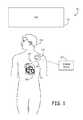
- FIG. 1is a schematic illustration of a medical system including an MRI scanner, and an implantable cardiac rhythm management system implanted within a torso of a human patient according to various embodiments of the present invention
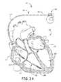
- FIG. 2Ais a schematic view of an illustrative pulse generator and lead implanted within the body of a patient which may be used in accordance with some embodiments of the present invention
- FIG. 2Bis a schematic view showing a simplified equivalence circuit for the lead of FIG. 2A
- FIG. 3is a schematic view illustrating an exemplary lead that may be used in accordance with one or more embodiments of the present invention
- FIG. 4is a transverse cross-sectional view of the lead of FIG. 3 taken along the line 4 - 4 in FIG. 3 ;
- FIG. 5illustrates invention detail of a multi-layer coil conductor utilized in the lead of FIG. 3 according to an embodiment of the present invention.
- various embodiments of the present inventionrelate to cardiac rhythm management (CRM) systems incorporating new lead designs advantageously adapted for operation in a magnetic resonance imaging (MRI) environment.
- the leadsincluding conductor designs configured to provide suitable electrical performance for delivering pacing and/or defibrillation shock therapy and to minimize the lead's reaction to applied electromagnetic energy during MRI procedures.
- embodiments of the present inventionmay be applicable to various other physiological measurements, treatments, IMD devices, lead types, and other non-invasive examination techniques in which conductive leads are exposed to time varying magnetic fields.
- the applications discussed hereinare not intended to be limiting, but instead exemplary.
- various embodimentsare applicable to all levels of sensory devices from a single IMD with a sensor to large networks of sensory devices.
- FIG. 1is a schematic illustration of a medical system 100 including an MRI scanner 110 , an implantable cardiac rhythm management (CRM) system 115 implanted within a torso of a human patient 120 , and one or more external device(s) 130 according to various embodiments.
- the external device(s) 130are capable of communicating with the CRM system 115 implanted within the patient 120 .
- the CRM system 115includes a pulse generator (PG) 140 and a lead 150 .
- PGpulse generator
- the PG 140is configured to deliver electrical therapeutic stimuli to the patient's heart 160 for providing tachycardia ventricular fibrillation, anti-bradycardia pacing, anti-tachycardia pacing, cardiac resynchronization therapy, and/or other types of therapy.
- the PG 140can be an implantable device such as a pacemaker, an ICD, a cardiac resynchronization therapy (CRT) device, a CRT device with defibrillation capabilities (a CRT-D device), or a comparable device.
- the PG 140can be implanted subcutaneously within the body, typically at a location such as in the patient's chest. In some embodiments, PG 140 can be implanted in or near the abdomen.
- the external device(s) 130may be a local or remote terminal or other device (e.g., a computing device and/or programming device), operable to communicate with the PG 140 from a location outside of the patient's body.
- external device 130can be any device external to the patient's body that is telemetry enabled and capable of communicating with the PG 140 .
- Examples of external devicescan include, but are not limited to, programmers (PRM), in-home monitoring devices, personal computers with telemetry devices, MRI scanner with a telemetry device, manufacturing test equipment, or wands.
- the PG 140communicates with the remote terminal 130 via a wireless communication interface.
- wireless communication interfacescan include, but are not limited to, radio frequency (RF), inductive, and acoustic telemetry interfaces.
- FIG. 2Ais a more detailed schematic view of the CRM system 115 including the illustrative PG 140 equipped with the lead 150 implanted within the body of a patient.
- CRM system 115includes PG 140 implanted near the patient's heart 160 and lead 150 having a distal portion implanted with the patient's heart 160 .
- the heart 160includes a right atrium 210 , a right ventricle 220 , a left atrium 230 , and a left ventricle 240 .
- the lead 150has a flexible body 200 including a proximal region 205 and a distal region 250 . As shown, the lead 150 is coupled to the PG 140 , and the distal region 250 of the lead body 200 is at least partially implanted at a desired location within the right ventricle 220 . As further shown, the lead 150 includes a pair of coil electrodes 255 , 257 along the distal region 250 , such that when implanted as shown in FIG. 2A , they are positioned within the right ventricle 220 and right atrium 210 , respectively. As explained and illustrated in further detail below, the lead 150 includes one or more electrical conductors within the lead body 200 (not visible in FIG.
- Electrodes 255 , 257electrically coupling the electrodes 255 , 257 to circuitry and other electrical components within the PG 140 for transmitting intrinsic cardiac signals from the heart 160 to the PG 140 and also for transmitting electrical shocks or low-voltage pacing stimuli to the heart 160 via the electrodes 255 , 257 or additional electrodes (not shown in FIG. 2A ).
- the illustrative embodimentdepicts only a single lead 150 inserted into the patient's heart 160 , in other embodiments multiple leads can be utilized so as to electrically stimulate other areas of the heart 160 .
- the distal portion of a second leadmay be implanted in the right atrium 210 .
- another leadmay be implanted within the coronary venous system to facilitate pacing the left ventricle, i.e., in a CRT or CRT-D system providing bi-ventricular pacing, as is known in the art.
- Other types of leadssuch as epicardial leads may also be utilized in addition to, or in lieu of, the lead 150 depicted in FIGS. 1-2 .
- the various embodiments of the present inventioncontemplate any multi-lead combinations and configurations for use in CRM systems 115 , whether now known or later developed.
- the lead 150conveys electrical signals between the heart 160 and the PG 140 .
- the lead 150can be utilized to deliver electrical therapeutic stimulus for pacing the heart 160 .
- the lead 150can be utilized to deliver high voltage electric shocks to the heart 160 via the electrodes 255 , 257 in response to an event such as a ventricular fibrillation.
- various embodiments of the present inventionrelate to new lead designs that allow for improved mechanical characteristics and safe operation in an MRI environment.
- traditional conductor cablesare replaced with low profile multi-layer coil conductors.
- the multi-layer coil conductorsallow lead designers to maintain a small lead profile in pace/sense lead applications while better controlling axial elongation of the lead under tensile load.
- FIG. 2Bis a schematic view showing a simplified equivalence circuit 260 for the lead 150 of FIG. 2A , representing the RF energy picked up on the lead 150 from RF electromagnetic energy produced by an MRI scanner.
- voltage (Vi) 265 in the circuit 260represents an equivalent source of energy picked up by the lead 150 from the MRI scanner.
- the length of the lead 150functions similar to an antenna, receiving the RF energy that is transmitted into the body from the MRI scanner.
- Voltage (Vi) 265 in FIG. 2Bmay represent, for example, the resultant voltage received by the lead 150 from the RF energy.
- the RF energy picked up by the lead 150may result, for example, from the rotating RF magnetic field produced by an MRI scanner, which generates an electric field in the plane perpendicular to the rotating magnetic field vector in conductive tissues.
- the tangential components of these electric fields along the length of the lead 150couple to the lead 150 .
- the voltage (Vi) 265is thus equal to the integration of the tangential electric field (i.e., the line integral of the electric field) along the length of the lead 150 .
- the Zl parameter 270 in the circuit 260represents the equivalent impedance exhibited by the lead 150 at the RF frequency of the MRI scanner.
- the impedance value Zl 270may represent, for example, the inductance or the equivalent impedance resulting from the parallel inductance and the coil turn by turn capacitance exhibited by the lead 150 at an RF frequency of 64 MHz for a 1.5 Tesla MRI scanner, or at an RF frequency of 128 MHz for a 3 Tesla MRI scanner.
- the impedance Zl of the lead 150is a complex quantity having a real part (i.e., resistance) and an imaginary part (i.e., reactance).
- Zb 275 in the circuit 260may represent the impedance of the body tissue at the point of lead contact.
- Zc 280may represent the capacitive coupling of the lead 150 to surrounding body tissue along the length of the lead 150 , which may provide a path for the high frequency current (energy) to leak into the surrounding tissue at the RF frequency of the MRI scanner.
- Minimizing the absorbed energyreduces the energy that is transferred to the body tissue at the point of lead contact with the body tissue.
- the lead 150has some amount of leakage into the surrounding tissue at the RF frequency of the MRI scanner. As further indicated by 275 , there is also an impedance at the point of contact of the lead electrodes 255 , 257 to the surrounding body tissue within the heart 160 .
- the temperature at the tip of the lead 150 where contact is typically made to the surrounding tissueis related in part to the power dissipated at 275 (i.e., at “Zb”), which, in turn, is related to the square of Vb.
- Zbthe power dissipated at 275
- Vi ( 265 ) and Zc ( 280 )it is thus desirable to minimize Vi ( 265 ) and Zc ( 280 ) while also maximizing the impedance Zl ( 270 ) of the lead 150 .
- the impedance Zl ( 270 ) of the lead 150can be increased at the RF frequency of the MRI scanner, which aids in reducing the energy dissipated into the surrounding body tissue at the point of contact 275 .
- the impedance of the lead 150can be increased by adding inductance to the lead 150 and/or by a suitable construction technique.
- the inductance of the lead 150is increased by selectively configuring the conductors used to supply electrical energy to the electrodes 255 , 257 .
- FIG. 3illustrates in further detail the exemplary lead 150 that may be used in accordance with one or more embodiments of the present invention.
- the lead body 200includes a proximal end 305
- the lead 150further includes a connector assembly 310 coupled to the proximal end 305 of the lead body, the coil electrodes 255 , 257 , and a tip electrode 312 which operates in the illustrated embodiment as a pace/sense electrode.
- the distal region 250 of the lead 150may include additional electrodes.
- the pair of coil electrodes 255 , 257can be used to function as shocking electrodes for providing a defibrillation shock to the heart 160 .
- the lead 150can include a low-voltage (e.g., ring) electrode proximal to the distal tip of the lead 150 which is also operable as a pace/sense electrode, which can be included in addition to, or in lieu of, the tip electrode 312 .
- the lead 150can incorporate any number of electrode configurations within the scope of the embodiments of the present invention.
- the connector assembly 310includes a connector body 320 and a terminal pin 325 .
- the connector assembly 310is coupled to the lead body 200 and can be configured to mechanically and electrically couple the lead to a header on PG 140 (see FIG. 1 and FIG. 2 ).
- the terminal pin 325extends proximally from the connector body 320 and in some embodiments is coupled to an inner conductor (not shown in FIG. 3 ) that extends longitudinally through the lead body 200 to the tip electrode 312 .
- the terminal pin 325can include an aperture extending therethrough communicating with a lumen defined by the inner conductor coil in order to accommodate a guide wire or an insertion stylet.
- the tip electrode 312is in the form of an electrically active fixation helix at the distal end of the lead 150 .
- the tip electrode 312can be an extendable/retractable helix supported by a mechanism to facilitate longitudinal translation of the helix relative to the lead body as the helix is rotated.
- the terminal pin 325may be rotatable relative to the connector body 320 and the lead body 200 such that rotation of the terminal pin 325 relative to the lead body 200 causes the inner conductor, and in turn, the helical tip electrode to rotate and translate longitudinally relative to the lead body 200 .
- Various mechanisms and techniques for providing extendable/retractable fixation helix assembliesare known to those of ordinary skill in the art, and need not be described in greater detail here.
- the pace/sense electrode(whether a solid tip electrode as described above or an active-fixation helix such as shown in FIG. 3 ) can be made of any suitable electrically conductive material such as Elgiloy, MP35N, tungsten, tantalum, iridium, platinum, titanium, palladium, stainless steel, as well as alloys of any of these materials.
- the coil electrodes 255 , 257can take on any configuration suitable for delivering a relatively high-voltage therapeutic shock to the heart for defibrillation therapy.
- the coil electrodes 255 , 257can be made from any suitable electrically conductive material such as those discussed in the preceding paragraph.
- the lead 150also includes a conductor (not shown in FIG. 3 ) within the lead body 200 electrically connecting the coil electrodes 255 , 257 to an electrical contact on the connector assembly 310 , which in turn is configured to electrically couple the coil electrodes 255 , 257 to electrical components within the PG 140 .
- FIG. 4is a transverse cross-sectional view of the lead 150 taken along the line 4 - 4 in FIG. 3 .
- the lead body 200includes an inner tubular member 380 and an outer tubular member 385 disposed over and bonded to the inner tubular member 380 .
- the tubular members 380 , 385can be made from any number of flexible, biocompatible insulative materials, including without limitation, polymers such as silicone and polyurethane, and copolymers thereof.
- the inner tubular member 380includes a plurality of lumens 390 , 395 , 400 , and conductors 410 , 415 , and 420 are disposed, respectively, in the lumens 390 , 395 , and 400 .
- Each of the conductors 410 , 415 and 420extends longitudinally within the respective lumen 390 , 395 , 400 , and is electrically coupled to an electrode (e.g., the electrodes 312 , 255 , or 257 in FIG. 3 ) and also to an electrical contact of the connector assembly 310 .
- the lead body 200does not include separate, coaxial tubular members, but instead, includes only a single tubular member (e.g., the member 380 ) including one or more longitudinal lumens for housing the requisite conductors.
- the three lumens 390 , 395 , 400 of the inner tubular member 380are shown having different diameters. In other embodiments, however, the relative dimensions and/or locations of the lumens 390 , 395 , 400 may vary from that shown.
- the inner tubular member 380may include a greater or lesser number of lumens, depending on the particular configuration of the lead 150 .
- the inner tubular member 380may include a greater number of lumens to house additional conductor wires and/or electrode coils within the lead 150 for supplying current to other shocking coils and/or pace/sense electrodes.
- the conductor 410is a single layer coil conductor such as would be used in conjunction with a conventional, low-voltage pace/sense electrode, e.g., the tip electrode 312 .
- the coil conductor 410is configured to have a relatively high impedance when exposed to electromagnetic energy such as that present during an MRI scan.
- the coil conductor 410is configured according to the various embodiments described, for example, in U.S. Patent Application Publication No. 2009/0198314, which is incorporated herein by reference in its entirety.
- the increased impedanceaids in reducing the energy dissipated into the surrounding body tissue at or near the lead electrode(s).
- the conductor 410 and the lumen 390are omitted.
- the conductors 415 and 420are multi-layer conductor assemblies incorporated into the lead 150 to provide a conditionally-safe MRI-compatible lead design, as well as to provide improved fatigue resistance and other mechanical properties during delivery and under chronic operating conditions.
- the multi-layer coil conductors 415 , 420include multiple coil layers having selectively controlled coil properties (e.g., pitch, outside diameter, filar thickness, etc.) to make a highly inductive, highly conductive, small diameter conductor that has suitable mechanical characteristics for a stimulation/sensing lead body.
- the coil conductor 415is a three-layer conductor and the coil conductor 420 is a two-layer conductor.
- multi-layer coil conductors utilizing more than three coil layerscan be utilized.
- the single layer coil conductor 410can be replaced with a multi-layer coil conductor similar or identical to the coil conductor 415 and/or 420 .
- FIG. 5is a more detailed side view of the coil conductor 420 according to one embodiment of the present invention.
- the multi-layer coil conductor 420is a three-layer coil conductor 420 including an outer coil layer 422 , a middle coil layer 425 and an inner coil layer 430 .
- the outer coil layer 422is disposed about the middle coil layer 425 which is disposed about the inner coil layer 430 .
- the outer, middle, and inner coil layers 422 , 425 , 430are electrically coupled to one another in parallel at least at their the proximal ends (i.e., at or near the connector assembly) as well as at their distal ends (i.e., at the electrode 255 ), so as to provide parallel conductive paths between the connector assembly 310 and the electrode 255 .
- the parameters of the coil layers 422 , 425 and 430are configured such that the multi-layer coil conductor 420 has a maximum DC resistance of about 3.0-3.5 ohms, and a high impedance when exposed to an external alternating magnetic field characterized by frequencies associated with MRI scans.
- the two-layer coil conductor 415can be configured in substantially the same manner as the coil conductor 420 shown in FIG. 5 while only including two coil conductor layers.
- the outer layer 422 of the coil conductor 420can be wound to coil diameter D o of less than about 0.013 inches.
- the outer layeris close pitched and can have one or more filars having a maximum filar thickness of about 0.004 inches.
- the outer layermay or may not be present depending on the desired application of the lead.
- the outer layermay be used to change the resistance of the multi-layer coil conductor 420 .
- the outer layer 422may have a filar thickness of from about 0.001 to about 0.004 inches.
- the middle layer 425 of the coil conductor 420is close pitched and can be wound to a coil diameter D m less than the inner diameter of the outer coil layer 422 .
- the middle layercan have one or more filars having a maximum filar thickness of from about 0.0007 to about 0.003 inches.
- the inner coil layer 430 of the coil conductor 420is close pitched and can be wound to a coil diameter D i less than the inner diameter of the middle layer 425 .
- the inner layercan have one or more filars having a maximum filar thickness of from about 0.0007 to about 0.001 inches.
- multi-layer coil conductor 420utilizes different ranges of dimensions and other parameters (e.g., filar count) of the respective coil layers 422 , 425 , 430 depending on the operational needs for the lead 150 .
- the filar materialcan be any suitable material exhibiting the desired electrical and mechanical properties.
- the filars of the outer, middle, and/or inner coil layers 422 , 425 , 430are made of drawn filled tube (DFT) wire including a silver core (about 40%) with an MP35N or tantalum cladding.
- the outer, middle, and/or inner coil layers 422 , 425 , 430are made of DFT wire including a tantalum core with a MP35N cladding.
- the coil layers 422 , 425 , 430may be comprised of the same or different materials, and each of the coil layers 422 , 425 , 430 may include different silver fill levels.
- the filars of each layer of the coil conductor 420are wound in the same pitch direction. That is, the individual filars of each coil layer are wound to have either a right-hand pitch or a left-hand pitch when viewing the coil along its longitudinal axis.
- one or more of the coil layers 422 , 425 , 430has a variable coil pitch along its length, which operates to de-tune the coil conductor 420 to reduce the effect of externally applied electromagnetic radiation (i.e., due to an MRI chest scan).
- the individual coil layers 422 , 425 and 430can be separately optimized to each exhibit a different inductance, e.g., by modifying the filar thickness, pitch, and/or coil layer diameter, to further modify the performance of the lead 150 under MRI conditions.
- Some embodiments of the present inventioninclude one or more layers of insulation between one or more of the adjacent coil layers 422 , 425 or 430 .
- the individual filars or the coil layers 422 , 425 , and/or 430are individually insulated. Any suitable insulation material can be utilized, if desired.
- Exemplary insulating materials for the filars and/or between the coil layersinclude ethylene tetrafluoroethylene (ETFE), polytetrafluoroethylene (PTFE), expanded PTFE (ePTFE), silicone, and the copolymers of the foregoing.
- the various embodiments of the lead 150 described aboveadvantageously minimize induced currents in the lead conductors resulting from exposure to external MRI electromagnetic fields. This is in contrast to conventional lead systems utilizing stranded cable conductors to transmit the shocking currents from the PG to the shocking electrodes. While such cable conductors provide excellent electrical performance for delivering anti-tachycardia therapy, stranded cable conductors also have a low impedance and thus are susceptible to generation of induced currents when exposed to an alternating electromagnetic field such as that present during an MRI scan.
- Various embodiments of the present inventioncan result in lead 150 exhibiting a temperature rise when exposed to MRI radiation of approximately half that experienced utilizing traditional high energy cables which are conventionally utilized to supply energy to high-voltage shocking coils in defibrillation leads.
- the high impedance conductor configurations for the lead 150 described aboveminimize the effects of MRI radiation while still providing suitable electrical performance for use in anti-tachycardia therapy applications.
- the design parameters of the multi-layer coil conductorscan be tuned to control the mechanical properties, e.g., effective spring constant and thus stiffness of the overall lead assembly, bending stiffness, and the like. Such tuning may enable the user minimize stresses (loads) on adjacent (distal) polymer components, minimize the potential for shear bond failure, facilitate/control the lead bias shape, and minimize the impact of axial length tolerance stack-up during assembly, in both low and high voltage lead applications.
- the shocking coils 255 , 257see FIGS.
- the lead 150includes only one or more low-voltage pace/sense electrodes such as the tip electrode 312 and additional ring electrodes along the lead 150 .
- multi-layer coil conductorssuch as the coil conductors 425 and/or 420 can be utilized to provide sufficient electrical performance in a low-profile design and also optimal mechanical characteristics such as axial stiffness relative to that of adjacent insulative components such as the lead body 200 .
- the multi-layer coil conductor 415 and/or 420can be tuned to control the effective spring constant (expressed in force per unit length) of the coil conductor 415 and/or 420 so as to reduce or eliminate the difference in axial stiffness between the conductor coil and the adjacent insulating elements (i.e., lead body 200 components).
- the coil conductor spring constant/axial stiffnessBy controlling and optimizing the coil conductor spring constant/axial stiffness in this way, the overall axial strength of the polymeric lead body components can be maintained, for example, where the coil conductor 415 , 420 terminates proximal to the lead body component.
- Exemplary design parameters that can be varied to tune/optimize the mechanical characteristics discussed abovecan include, without limitation, the selection of conductor materials, number of layers, wind geometry, pitch, filar diameter, number of filars, and others.
- the various embodiments of the lead 150 of the present inventionmay optionally incorporate other features or techniques to minimize the effects of MRI radiation.
- shieldingmay be added to the lead 150 to further reduce the amount of electromagnetic energy picked up from the lead 150 .
- the energy picked up from the shieldingcan be coupled to the patient's body along the length of the lead 150 , preventing the energy from coupling to the lead tip.
- the transfer of intercepted energy by the shielding along the length of the shielding/leadcan also be inhibited by dissipating the energy as resistive loss, using resistive material for the shielding construction.
Landscapes
- Health & Medical Sciences (AREA)
- Radiology & Medical Imaging (AREA)
- Heart & Thoracic Surgery (AREA)
- Engineering & Computer Science (AREA)
- Biomedical Technology (AREA)
- Nuclear Medicine, Radiotherapy & Molecular Imaging (AREA)
- Life Sciences & Earth Sciences (AREA)
- Animal Behavior & Ethology (AREA)
- General Health & Medical Sciences (AREA)
- Public Health (AREA)
- Veterinary Medicine (AREA)
- Cardiology (AREA)
- Electrotherapy Devices (AREA)
- Neurology (AREA)
Abstract
Description
Vb=Vi Zbe/(Zbe+FZl),
where Zbe=Zb in parallel with Zc.
Claims (20)
Priority Applications (1)
| Application Number | Priority Date | Filing Date | Title |
|---|---|---|---|
| US14/327,662US9199077B2 (en) | 2009-12-31 | 2014-07-10 | MRI conditionally safe lead with multi-layer conductor |
Applications Claiming Priority (3)
| Application Number | Priority Date | Filing Date | Title |
|---|---|---|---|
| US29155709P | 2009-12-31 | 2009-12-31 | |
| US12/940,592US8798767B2 (en) | 2009-12-31 | 2010-11-05 | MRI conditionally safe lead with multi-layer conductor |
| US14/327,662US9199077B2 (en) | 2009-12-31 | 2014-07-10 | MRI conditionally safe lead with multi-layer conductor |
Related Parent Applications (1)
| Application Number | Title | Priority Date | Filing Date |
|---|---|---|---|
| US12/940,592ContinuationUS8798767B2 (en) | 2009-12-31 | 2010-11-05 | MRI conditionally safe lead with multi-layer conductor |
Publications (2)
| Publication Number | Publication Date |
|---|---|
| US20140324139A1 US20140324139A1 (en) | 2014-10-30 |
| US9199077B2true US9199077B2 (en) | 2015-12-01 |
Family
ID=43432139
Family Applications (2)
| Application Number | Title | Priority Date | Filing Date |
|---|---|---|---|
| US12/940,592Active2031-06-28US8798767B2 (en) | 2009-12-31 | 2010-11-05 | MRI conditionally safe lead with multi-layer conductor |
| US14/327,662ActiveUS9199077B2 (en) | 2009-12-31 | 2014-07-10 | MRI conditionally safe lead with multi-layer conductor |
Family Applications Before (1)
| Application Number | Title | Priority Date | Filing Date |
|---|---|---|---|
| US12/940,592Active2031-06-28US8798767B2 (en) | 2009-12-31 | 2010-11-05 | MRI conditionally safe lead with multi-layer conductor |
Country Status (6)
| Country | Link |
|---|---|
| US (2) | US8798767B2 (en) |
| EP (1) | EP2519305B1 (en) |
| JP (1) | JP5542217B2 (en) |
| CN (1) | CN102655908B (en) |
| AU (1) | AU2010337313B2 (en) |
| WO (1) | WO2011081713A1 (en) |
Cited By (2)
| Publication number | Priority date | Publication date | Assignee | Title |
|---|---|---|---|---|
| US9504822B2 (en) | 2012-10-18 | 2016-11-29 | Cardiac Pacemakers, Inc. | Inductive element for providing MRI compatibility in an implantable medical device lead |
| US9504821B2 (en) | 2014-02-26 | 2016-11-29 | Cardiac Pacemakers, Inc. | Construction of an MRI-safe tachycardia lead |
Families Citing this family (42)
| Publication number | Priority date | Publication date | Assignee | Title |
|---|---|---|---|---|
| US7610101B2 (en) | 2006-11-30 | 2009-10-27 | Cardiac Pacemakers, Inc. | RF rejecting lead |
| AU2008335462B2 (en) | 2007-12-06 | 2014-02-20 | Cardiac Pacemakers, Inc. | Implantable lead having a variable coil conductor pitch |
| WO2009100003A1 (en) | 2008-02-06 | 2009-08-13 | Cardiac Pacemakers, Inc. | Lead with mri compatible design features |
| US8103360B2 (en) | 2008-05-09 | 2012-01-24 | Foster Arthur J | Medical lead coil conductor with spacer element |
| US9084883B2 (en) | 2009-03-12 | 2015-07-21 | Cardiac Pacemakers, Inc. | Thin profile conductor assembly for medical device leads |
| ES2547713T3 (en) | 2009-06-26 | 2015-10-08 | Cardiac Pacemakers, Inc. | Bypass of a medical device that includes a single-coil coil with improved torque transmission capacity and reduced RM heating |
| US8825158B2 (en) | 2009-08-25 | 2014-09-02 | Lamda Nu, Llc | Method and apparatus for detection of lead conductor anomalies using dynamic electrical parameters |
| US9254380B2 (en) | 2009-10-19 | 2016-02-09 | Cardiac Pacemakers, Inc. | MRI compatible tachycardia lead |
| US9750944B2 (en) | 2009-12-30 | 2017-09-05 | Cardiac Pacemakers, Inc. | MRI-conditionally safe medical device lead |
| WO2011081713A1 (en) | 2009-12-31 | 2011-07-07 | Cardiac Pacemakers, Inc. | Mri conditionally safe lead with multi-layer conductor |
| US8391994B2 (en) | 2009-12-31 | 2013-03-05 | Cardiac Pacemakers, Inc. | MRI conditionally safe lead with low-profile multi-layer conductor for longitudinal expansion |
| US8825181B2 (en) | 2010-08-30 | 2014-09-02 | Cardiac Pacemakers, Inc. | Lead conductor with pitch and torque control for MRI conditionally safe use |
| EP2476455A1 (en)* | 2011-01-13 | 2012-07-18 | BIOTRONIK SE & Co. KG | Implantable electrode lead |
| CN103083808B (en)* | 2011-10-28 | 2016-04-27 | 清华大学 | Pacing lead and pacemaker |
| CN103083806B (en) | 2011-10-28 | 2016-06-08 | 清华大学 | Pacing lead and pacemaker |
| CN103093865B (en) | 2011-10-28 | 2015-06-03 | 清华大学 | Pacemaker electrode line and pacemaker |
| CN103083807B (en)* | 2011-10-28 | 2016-04-27 | 清华大学 | The preparation method of pacing lead |
| CN103093858B (en) | 2011-10-28 | 2016-10-19 | 清华大学 | Pacemaker lead and pacemaker |
| CN103093859B (en) | 2011-10-28 | 2015-08-26 | 清华大学 | Pacing lead and pacemaker |
| US8666512B2 (en) | 2011-11-04 | 2014-03-04 | Cardiac Pacemakers, Inc. | Implantable medical device lead including inner coil reverse-wound relative to shocking coil |
| CN103957979B (en)* | 2011-11-29 | 2017-09-12 | 皇家飞利浦有限公司 | For the pipe being introduced into subject |
| AU2013249088B2 (en)* | 2012-04-20 | 2015-12-03 | Cardiac Pacemakers, Inc. | Implantable medical device lead including a unifilar coiled cable |
| US9272150B2 (en) | 2012-06-01 | 2016-03-01 | Lambda Nu Technology Llc | Method for detecting and localizing insulation failures of implantable device leads |
| US8954168B2 (en) | 2012-06-01 | 2015-02-10 | Cardiac Pacemakers, Inc. | Implantable device lead including a distal electrode assembly with a coiled component |
| US8812103B2 (en) | 2012-06-01 | 2014-08-19 | Lamda Nu, Llc | Method for detecting and treating insulation lead-to-housing failures |
| JP6069499B2 (en) | 2012-08-31 | 2017-02-01 | カーディアック ペースメイカーズ, インコーポレイテッド | Lead wire with low peak MRI heating |
| WO2014074876A1 (en)* | 2012-11-09 | 2014-05-15 | Cardiac Pacemakers, Inc. | Implantable lead having a lumen with a wear-resistant liner |
| US9675799B2 (en) | 2012-12-05 | 2017-06-13 | Lambda Nu Technology Llc | Method and apparatus for implantable cardiac lead integrity analysis |
| US10840005B2 (en) | 2013-01-25 | 2020-11-17 | Vishay Dale Electronics, Llc | Low profile high current composite transformer |
| US10039919B2 (en) | 2013-04-30 | 2018-08-07 | Lambda Nu Technology Llc | Methods and apparatus for detecting and localizing partial conductor failures of implantable device leads |
| US9486624B2 (en) | 2013-06-13 | 2016-11-08 | Lambda Nu Technology Llc | Detection of implantable lead failures by differential EGM analysis |
| US10118031B2 (en) | 2013-06-28 | 2018-11-06 | Lambda Nu Technology Llc | Method and apparatus for implantable cardiac lead integrity analysis |
| US9636500B2 (en) | 2014-03-25 | 2017-05-02 | Lambda Nu Technology Llc | Active surveillance of implanted medical leads for lead integrity |
| US11511085B2 (en) | 2015-11-18 | 2022-11-29 | Heraeus Deutschland GmbH & Co. KG | Torque coil and method |
| US10252069B1 (en) | 2015-11-19 | 2019-04-09 | Lambda Nu Technology Llc | Micro-charge ICD lead testing method and apparatus |
| EP3442651B1 (en)* | 2016-04-15 | 2022-04-13 | Medtronic, Inc. | Medical device lead assembly with variable pitch coil |
| US11666251B2 (en) | 2016-10-31 | 2023-06-06 | Heraeus Deutschland GmbH & Co. KG | Signal and torque transmitting torque coil |
| US11129980B2 (en) | 2017-03-02 | 2021-09-28 | Saluda Medical Pty Limited | Electrode assembly |
| US10543364B2 (en) | 2017-04-07 | 2020-01-28 | Lambda Nu Technology Llc | Detection of lead electrode dislodgement using cavitary electrogram |
| CN110996788B (en)* | 2017-08-07 | 2023-05-16 | 德普伊新特斯产品公司 | Folded MRI safety coil assembly |
| WO2021062480A1 (en) | 2019-10-04 | 2021-04-08 | Saluda Medical Pty Limited | Lead for an active implantable medical device |
| US11672976B2 (en) | 2019-10-10 | 2023-06-13 | Saluda Medical Pty Limited | Lead for an active implantable medical device with decoy |
Citations (309)
| Publication number | Priority date | Publication date | Assignee | Title |
|---|---|---|---|---|
| US3614692A (en) | 1970-06-02 | 1971-10-19 | Magnetech Ind Inc | Variable induction device |
| US4131759A (en) | 1977-08-10 | 1978-12-26 | United States Steel Corporation | Slip sleeve mechanism for a strength tapered caged armored electromechanical cable |
| US4135518A (en) | 1976-05-21 | 1979-01-23 | Medtronic, Inc. | Body implantable lead and electrode |
| US4146036A (en) | 1977-10-06 | 1979-03-27 | Medtronic, Inc. | Body-implantable lead with protector for tissue securing means |
| US4209019A (en) | 1979-01-05 | 1980-06-24 | Medtronic, Inc. | Stylet insertion guide and rotation control device for use with body implantable lead |
| US4253462A (en) | 1979-08-09 | 1981-03-03 | Medtronic, Inc. | Stylet |
| US4350169A (en) | 1979-01-05 | 1982-09-21 | Medtronic, Inc. | Flexible tip stiffening stylet for use with body implantable lead |
| US4381013A (en) | 1981-03-19 | 1983-04-26 | Medtronic, Inc. | "J" Stylet wire |
| US4404125A (en) | 1981-10-14 | 1983-09-13 | General Electric Company | Polyphenylene ether resin compositions for EMI electromagnetic interference shielding |
| US4437474A (en) | 1982-07-16 | 1984-03-20 | Cordis Corporation | Method for making multiconductor coil and the coil made thereby |
| US4484586A (en) | 1982-05-27 | 1984-11-27 | Berkley & Company, Inc. | Hollow conductive medical tubing |
| US4493329A (en) | 1982-08-19 | 1985-01-15 | Lynn Crawford | Implantable electrode having different stiffening and curvature maintaining characteristics along its length |
| US4574800A (en) | 1984-12-07 | 1986-03-11 | Cordis Corporation | Implanted lead extractor |
| US4643202A (en) | 1985-04-15 | 1987-02-17 | Cordis Corporation | Multi-material insulation sheath for pacer lead |
| US4643203A (en) | 1982-07-01 | 1987-02-17 | Molins Plc | Conveying and uniting rod-like articles of the tobacco industry |
| US4649938A (en) | 1985-04-29 | 1987-03-17 | Mcarthur William A | Tissue-stimulating electrode having sealed, low-friction extendable/retractable active fixation means |
| US4869970A (en) | 1986-07-14 | 1989-09-26 | Shipley Company Inc. | Radiation attenuation shielding |
| US5002067A (en) | 1989-08-23 | 1991-03-26 | Medtronic, Inc. | Medical electrical lead employing improved penetrating electrode |
| US5003975A (en) | 1988-04-19 | 1991-04-02 | Siemens-Pacesetter, Inc. | Automatic electrode configuration of an implantable pacemaker |
| US5020545A (en) | 1990-01-23 | 1991-06-04 | Siemens-Pacesetter, Inc. | Cardiac lead assembly and method of attaching a cardiac lead assembly |
| US5056516A (en) | 1989-11-02 | 1991-10-15 | Intermedics, Inc. | Implantable endocordial lead with torque-transmitting lanyard |
| US5074313A (en) | 1989-03-20 | 1991-12-24 | Cardiac Pacemakers, Inc. | Porous electrode with enhanced reactive surface |
| US5144960A (en) | 1991-03-20 | 1992-09-08 | Medtronic, Inc. | Transvenous defibrillation lead and method of use |
| US5201865A (en) | 1991-10-28 | 1993-04-13 | Medtronic, Inc. | Medical lead impedance measurement system |
| US5217010A (en) | 1991-05-28 | 1993-06-08 | The Johns Hopkins University | Ecg amplifier and cardiac pacemaker for use during magnetic resonance imaging |
| US5222506A (en) | 1991-07-29 | 1993-06-29 | Medtronic, Inc. | Implantable medical lead with electrical cross-over adaptor |
| US5231996A (en) | 1992-01-28 | 1993-08-03 | Medtronic, Inc. | Removable endocardial lead |
| US5241957A (en) | 1991-11-18 | 1993-09-07 | Medtronic, Inc. | Bipolar temporary pacing lead and connector and permanent bipolar nerve wire |
| US5243911A (en) | 1990-09-18 | 1993-09-14 | Dow Robert L | Attenuator for protecting electronic equipment from undesired exposure to RF energy and/or lightning |
| US5246014A (en) | 1991-11-08 | 1993-09-21 | Medtronic, Inc. | Implantable lead system |
| US5259395A (en) | 1992-01-15 | 1993-11-09 | Siemens Pacesetter, Inc. | Pacemaker lead with extendable retractable lockable fixing helix |
| US5300108A (en) | 1993-01-05 | 1994-04-05 | Telectronics Pacing Systems, Inc. | Active fixation lead with a dual-pitch, free spinning compound screw |
| US5324322A (en) | 1992-04-20 | 1994-06-28 | Case Western Reserve University | Thin film implantable electrode and method of manufacture |
| US5330522A (en) | 1992-12-29 | 1994-07-19 | Siemens Pacesetter, Inc. | Ring electrode for a multilumen lead and method of constructing a multilumen lead |
| US5354327A (en) | 1993-04-07 | 1994-10-11 | Medtronic, Inc. | Conductor coil with specific ratio of torque to bending stiffness |
| US5370666A (en) | 1992-06-05 | 1994-12-06 | Siemens-Elema Ab | Pacemaker with power-consuming component inhibited during storage |
| US5378234A (en) | 1993-03-15 | 1995-01-03 | Pilot Cardiovascular Systems, Inc. | Coil polymer composite |
| US5387199A (en) | 1992-02-24 | 1995-02-07 | Baxter International Inc. | Polymer blends for torque transmitting catheters |
| US5417208A (en) | 1993-10-12 | 1995-05-23 | Arrow International Investment Corp. | Electrode-carrying catheter and method of making same |
| US5425755A (en) | 1992-12-04 | 1995-06-20 | Pacesetter, Inc. | Rotatable pin, screw-in pacing and sensing lead having Teflon-coated conductor coil |
| US5456707A (en) | 1993-10-22 | 1995-10-10 | Vitatron Medical Bv | Pacing lead with improved torsion characteristics |
| US5476485A (en) | 1993-09-21 | 1995-12-19 | Pacesetter, Inc. | Automatic implantable pulse generator |
| US5483022A (en) | 1994-04-12 | 1996-01-09 | Ventritex, Inc. | Implantable conductor coil formed from cabled composite wire |
| WO1996006655A1 (en) | 1994-08-29 | 1996-03-07 | Angeion Corporation | Low profile defibrillation catheter |
| US5522875A (en) | 1994-07-28 | 1996-06-04 | Medtronic, Inc. | Medical electrical lead system having a torque transfer stylet |
| US5522872A (en) | 1994-12-07 | 1996-06-04 | Ventritex, Inc. | Electrode-conductor sleeve joint for cardiac lead |
| US5534018A (en) | 1994-11-30 | 1996-07-09 | Medtronic, Inc. | Automatic lead recognition for implantable medical device |
| US5542173A (en) | 1993-09-24 | 1996-08-06 | Ventritex, Inc. | Method of making flexible defibrillation electrode |
| US5545205A (en) | 1989-12-08 | 1996-08-13 | Cardiac Pacemakers, Inc. | Unitary intravascular defibrillating catheter with bipolar sensing |
| US5549646A (en) | 1994-12-06 | 1996-08-27 | Pacesetter, Inc. | Periodic electrical lead intergrity testing system and method for implantable cardiac stimulating devices |
| US5554139A (en) | 1993-12-24 | 1996-09-10 | Terumo Kabushiki Kaisha | Catheter |
| US5574249A (en) | 1994-07-18 | 1996-11-12 | Lindsay Audiophile Inc. | High resistivity inner shields for cabinets housing electronic circuitry |
| US5584873A (en) | 1995-05-08 | 1996-12-17 | Medtronic, Inc. | Medical lead with compression lumens |
| US5599576A (en) | 1995-02-06 | 1997-02-04 | Surface Solutions Laboratories, Inc. | Medical apparatus with scratch-resistant coating and method of making same |
| US5609622A (en) | 1993-02-01 | 1997-03-11 | W. L. Gore & Associates, Inc. | Implantable electrode with conductive polytetrafluoroethylene elecrode |
| US5618208A (en) | 1994-06-03 | 1997-04-08 | Siemens Medical Systems, Inc. | Fully insulated, fully shielded electrical connector arrangement |
| US5649974A (en) | 1992-07-27 | 1997-07-22 | Angeion Corporation | Low profile defibrillation catheter |
| US5727552A (en) | 1996-01-11 | 1998-03-17 | Medtronic, Inc. | Catheter and electrical lead location system |
| US5727553A (en) | 1996-03-25 | 1998-03-17 | Saad; Saad A. | Catheter with integral electromagnetic location identification device |
| US5728149A (en) | 1995-12-20 | 1998-03-17 | Medtronic, Inc. | Integral spiral band electrode for transvenous defibrillation leads |
| US5755742A (en) | 1996-11-05 | 1998-05-26 | Medtronic, Inc. | Cardioversion/defibrillation lead impedance measurement system |
| US5760341A (en) | 1996-09-10 | 1998-06-02 | Medtronic, Inc. | Conductor cable for biomedical lead |
| US5766227A (en) | 1997-03-04 | 1998-06-16 | Nappholz; Tibor A. | EMI detection in an implantable pacemaker and the like |
| US5800496A (en) | 1996-06-24 | 1998-09-01 | Medtronic, Inc. | Medical electrical lead having a crush resistant lead body |
| US5810887A (en) | 1996-08-23 | 1998-09-22 | Rhythm Technologies, Inc. | Temporary catheter |
| US5817136A (en) | 1997-05-02 | 1998-10-06 | Pacesetter, Inc. | Rate-responsive pacemaker with minute volume determination and EMI protection |
| US5824026A (en) | 1996-06-12 | 1998-10-20 | The Spectranetics Corporation | Catheter for delivery of electric energy and a process for manufacturing same |
| US5833715A (en) | 1992-09-03 | 1998-11-10 | Pacesetter, Inc. | Implantable stimulation lead having an advanceable therapeutic drug delivery system |
| US5849031A (en) | 1997-12-16 | 1998-12-15 | Medtronic, Inc. | Method and apparatus for termination of tachyarrhythmias |
| US5891114A (en) | 1997-09-30 | 1999-04-06 | Target Therapeutics, Inc. | Soft-tip high performance braided catheter |
| US5891179A (en) | 1997-11-20 | 1999-04-06 | Paceseter, Inc. | Method and apparatus for monitoring and displaying lead impedance in real-time for an implantable medical device |
| US5935159A (en) | 1996-12-19 | 1999-08-10 | Medtronic, Inc. | Medical electrical lead |
| US5957966A (en) | 1998-02-18 | 1999-09-28 | Intermedics Inc. | Implantable cardiac lead with multiple shape memory polymer structures |
| US5957970A (en) | 1998-02-18 | 1999-09-28 | Medtronic, Inc. | Method of fabricating a medical electrical lead |
| US5968087A (en) | 1996-12-19 | 1999-10-19 | Medtronic, Inc. | Multi-component lead body for medical electrical leads |
| US6016447A (en) | 1998-10-27 | 2000-01-18 | Medtronic, Inc. | Pacemaker implant recognition |
| US6057031A (en) | 1997-08-21 | 2000-05-02 | Gfe Metalle Und Materialien Gmbh. | Plastic substrate with thin metal-containing layer |
| US6078840A (en) | 1997-04-30 | 2000-06-20 | Medtronic, Inc. | Medical electrical lead having improved fixation |
| US6083216A (en) | 1999-01-05 | 2000-07-04 | Intermedics Inc. | Bent cardiac lead with shape memory torque coil |
| US6101417A (en) | 1998-05-12 | 2000-08-08 | Pacesetter, Inc. | Implantable electrical device incorporating a magnetoresistive magnetic field sensor |
| US6106522A (en) | 1993-10-14 | 2000-08-22 | Ep Technologies, Inc. | Systems and methods for forming elongated lesion patterns in body tissue using straight or curvilinear electrode elements |
| US6141593A (en) | 1998-11-10 | 2000-10-31 | Intermedics Inc. | Cardiac lead with ETEE coated DBS coil |
| US6143013A (en) | 1995-04-28 | 2000-11-07 | Target Therapeutics, Inc. | High performance braided catheter |
| US6178355B1 (en) | 1997-04-29 | 2001-01-23 | Medtronic, Inc. | Intracardiac defibrillation leads |
| US6192280B1 (en) | 1999-06-02 | 2001-02-20 | Medtronic, Inc. | Guidewire placed implantable lead with tip seal |
| US6208881B1 (en) | 1998-10-20 | 2001-03-27 | Micropure Medical, Inc. | Catheter with thin film electrodes and method for making same |
| US6249708B1 (en) | 1997-08-26 | 2001-06-19 | Angeion Corporation | Fluted channel construction for a multi-conductor catheter lead |
| US6256541B1 (en) | 1998-04-17 | 2001-07-03 | Cardiac Pacemakers, Inc. | Endocardial lead having defibrillation and sensing electrodes with septal anchoring |
| US6259954B1 (en) | 1999-02-18 | 2001-07-10 | Intermedics Inc. | Endocardial difibrillation lead with strain-relief coil connection |
| US6289250B1 (en) | 1998-05-27 | 2001-09-11 | Kabushiki Kaisha Cardio-Pacing Research Laboratory | Implantable electrode lead |
| US6295476B1 (en) | 1999-11-01 | 2001-09-25 | Medtronic, Inc. | Medical lead conductor fracture visualization method and apparatus |
| US6304784B1 (en) | 1999-06-15 | 2001-10-16 | Arizona Board Of Regents, Acting For And On Behalf Of Arizona State University | Flexible probing device and methods for manufacturing the same |
| US6317633B1 (en) | 1999-01-19 | 2001-11-13 | Medtronic, Inc. | Implantable lead functional status monitor and method |
| US6360129B1 (en) | 1999-12-13 | 2002-03-19 | Cardiac Pacemakers, Inc. | Mannitol/hydrogel cap for tissue-insertable connections |
| US20020065544A1 (en) | 1999-11-29 | 2002-05-30 | Medtronic, Inc. | Medical electrical lead having variable bending stiffness |
| US6400992B1 (en) | 1999-03-18 | 2002-06-04 | Medtronic, Inc. | Co-extruded, multi-lumen medical lead |
| US20020072769A1 (en) | 2000-12-11 | 2002-06-13 | Sergiu Silvian | System and method of protecting transformer-driven switches from external magnetic fields |
| US6428537B1 (en) | 1998-05-22 | 2002-08-06 | Scimed Life Systems, Inc. | Electrophysiological treatment methods and apparatus employing high voltage pulse to render tissue temporarily unresponsive |
| US20020111664A1 (en) | 1999-09-29 | 2002-08-15 | Cardiac Pacemakers, Inc. | Low profile, ventricular, transvenous, epicardial defibrillation lead |
| US20020128689A1 (en) | 2001-02-20 | 2002-09-12 | Connelly Patrick R. | Electromagnetic interference immune tissue invasive system |
| US6456888B1 (en) | 2000-08-18 | 2002-09-24 | Cardiac Pacemakers, Inc. | Geometry for coupling and electrode to a conductor |
| US20020144720A1 (en) | 1997-08-20 | 2002-10-10 | Zahorik Russell C. | Method and apparatus for selective removal of material from wafer alignment marks |
| US6493591B1 (en) | 2000-07-19 | 2002-12-10 | Medtronic, Inc. | Implantable active fixation lead with guidewire tip |
| US6501991B1 (en) | 2000-06-21 | 2002-12-31 | Medtronic, Inc. | Electrically-isolated multiple conductor lead body |
| US6501994B1 (en) | 1997-12-24 | 2002-12-31 | Cardiac Pacemakers, Inc. | High impedance electrode tip |
| US6510345B1 (en) | 2000-04-24 | 2003-01-21 | Medtronic, Inc. | System and method of bridging a transreceiver coil of an implantable medical device during non-communication periods |
| US6516230B2 (en) | 2000-04-26 | 2003-02-04 | Medtronic, Inc. | Medical electrical lead with fiber core |
| US20030028231A1 (en) | 2001-08-01 | 2003-02-06 | Cardiac Pacemakers, Inc. | Radiopaque drug collar for implantable endocardial leads |
| US6526321B1 (en) | 1998-06-05 | 2003-02-25 | Intermedics, Inc. | Method for making cardiac leads with zone insulated electrodes |
| US20030050680A1 (en) | 2001-09-07 | 2003-03-13 | Gibson Scott R. | Electronic lead for a medical implant device, method of making same, and method and apparatus for inserting same |
| US20030063946A1 (en) | 2000-12-18 | 2003-04-03 | Janet Williams | Disposable lotion applicator |
| US20030083726A1 (en) | 2001-10-31 | 2003-05-01 | Medtronic, Inc. | Method and apparatus for shunting induced currents in an electrical lead |
| US20030083723A1 (en) | 2001-10-31 | 2003-05-01 | Wilkinson Jeffrey D. | Apparatus and method for shunting induced currents in an electrical lead |
| US6564107B1 (en) | 2000-08-21 | 2003-05-13 | Cardiac Pacemakers, Inc. | Coil-less lead system |
| US20030092303A1 (en) | 2001-11-09 | 2003-05-15 | Osypka Thomas P. | Multifilar conductor for cardiac leads |
| US20030093138A1 (en) | 2001-11-09 | 2003-05-15 | Osypka Thomas P. | High impedance drug eluting cardiac lead |
| US20030139794A1 (en) | 2002-01-18 | 2003-07-24 | Jenney Christopher R. | Body implantable lead including one or more conductive polymer electrodes and methods for fabricating same |
| US20030140931A1 (en) | 2002-01-29 | 2003-07-31 | Zeijlemaker Volkert A. | Medical implantable system for reducing magnetic resonance effects |
| US20030144719A1 (en) | 2002-01-29 | 2003-07-31 | Zeijlemaker Volkert A. | Method and apparatus for shielding wire for MRI resistant electrode systems |
| US20030144716A1 (en) | 2002-01-29 | 2003-07-31 | Reinke James D. | Method and apparatus for shunting induced currents in an electrical lead |
| US20030144705A1 (en) | 2002-01-29 | 2003-07-31 | Medtronic, Inc. | Methods and apparatus for controlling a pacing system in the presence of EMI |
| US20030144721A1 (en) | 2002-01-29 | 2003-07-31 | Villaseca Eduardo H. | Conditioning of coupled electromagnetic signals on a lead |
| US20030144718A1 (en) | 2002-01-29 | 2003-07-31 | Zeijlemaker Volkert A. | Method and apparatus for shielding coating for MRI resistant electrode systems |
| WO2003089045A2 (en) | 2002-04-11 | 2003-10-30 | Medtronic, Inc. | Implantable medical lead conductor insulation |
| US20030204217A1 (en) | 2002-04-25 | 2003-10-30 | Wilson Greatbatch | MRI-safe cardiac stimulation device |
| US20040014355A1 (en) | 2002-07-10 | 2004-01-22 | Osypka Thomas P. | Low profile cardiac leads |
| US6701191B2 (en) | 2001-05-30 | 2004-03-02 | Cardiac Pacemakers, Inc. | Lead having composite tubing |
| US20040064161A1 (en) | 2002-09-30 | 2004-04-01 | Gunderson Bruce D. | Method and apparatus for identifying lead-related conditions using lead impedance measurements |
| US20040064174A1 (en) | 2002-09-27 | 2004-04-01 | Belden Elisabeth L. | Methods and apparatus for joining small diameter conductors within medical electrical leads |
| US20040064173A1 (en) | 2002-09-27 | 2004-04-01 | Hine Douglas S. | Cardiac vein lead with flexible anode and method for forming same |
| US6721600B2 (en) | 2000-01-19 | 2004-04-13 | Medtronic, Inc. | Implantable lead functional status monitor and method |
| US6721604B1 (en) | 2000-07-27 | 2004-04-13 | Micronet Medical, Inc. | Reduced diameter, low resistance medical electrical lead |
| US20040088033A1 (en) | 2002-10-31 | 2004-05-06 | Smits Karel F.A.A. | Implantable medical lead designs |
| JP2004141679A (en) | 1996-04-30 | 2004-05-20 | Target Therapeutics Inc | Superelastic alloy braiding structure |
| US20040097965A1 (en) | 2002-11-19 | 2004-05-20 | Gardeski Kenneth C. | Multilumen body for an implantable medical device |
| US20040122490A1 (en) | 2002-09-25 | 2004-06-24 | Medtronic, Inc. | Implantable medical device communication system with pulsed power biasing |
| US20040153049A1 (en) | 2002-10-10 | 2004-08-05 | Hewitt Todd J. | Wire braid-reinforced microcatheter |
| US20040162600A1 (en) | 2003-02-14 | 2004-08-19 | Medtronic, Inc. | Reverse wound electrodes |
| US20040167442A1 (en) | 2003-02-26 | 2004-08-26 | Shireman Brice L. | Elongated intracorporal medical device |
| US20040172117A1 (en) | 2001-03-29 | 2004-09-02 | Rolf Hill | Electrically conductive lead and a method of producing such a lead |
| US20040193140A1 (en) | 2003-03-27 | 2004-09-30 | Scimed Life Systems,Inc. | Medical device |
| US6813521B2 (en) | 2001-04-17 | 2004-11-02 | Medtronic, Inc. | Medical electrical lead |
| US6813251B1 (en) | 1999-07-27 | 2004-11-02 | Intel Corporation | Split Transaction protocol for a bus system |
| US20040243210A1 (en) | 2003-05-30 | 2004-12-02 | Morgan Kevin L. | Fixation of a left heart medical lead in the coronary sinus |
| US20040267107A1 (en) | 2003-06-24 | 2004-12-30 | Medtronic, Inc. | Medical electrical lead conductor formed from modified MP35N alloy |
| US6850803B1 (en) | 2000-06-16 | 2005-02-01 | Medtronic, Inc. | Implantable medical device with a recharging coil magnetic shield |
| US20050030322A1 (en) | 1998-06-25 | 2005-02-10 | Gardos Thomas R. | Perceptually based display |
| US6854994B2 (en) | 2001-04-19 | 2005-02-15 | Medtronic, Inc. | Medical electrical lead connector arrangement including anti-rotation means |
| US6866044B2 (en) | 2000-09-18 | 2005-03-15 | Cameron Health, Inc. | Method of insertion and implantation of implantable cardioverter-defibrillator canisters |
| US20050070972A1 (en) | 2003-09-26 | 2005-03-31 | Wahlstrand Carl D. | Energy shunt for producing an MRI-safe implantable medical device |
| US20050090886A1 (en) | 2001-02-20 | 2005-04-28 | Biophan Technologies, Inc. | Medical device with an electrically conductive anti-antenna geometrical shaped member |
| US20050113876A1 (en) | 2003-04-02 | 2005-05-26 | Biophan Technologies, Inc. | Device and method for preventing magnetic-resonance imaging induced damage |
| JP2005515854A (en) | 2002-01-29 | 2005-06-02 | メドトロニック・インコーポレーテッド | Medical electrical leads |
| US6906256B1 (en) | 2002-01-22 | 2005-06-14 | Nanoset, Llc | Nanomagnetic shielding assembly |
| US20050136385A1 (en) | 2003-12-19 | 2005-06-23 | Brian Mann | Flexible lead for digital cardiac rhythm management |
| US6925334B1 (en) | 2003-08-04 | 2005-08-02 | Pacesetter, Inc. | Implantable medical lead having multiple, jointly insulated electrical conductors |
| US20050177135A1 (en) | 2004-02-06 | 2005-08-11 | Hildebrand Keith R. | Delivery of a sympatholytic cardiovascular agent to the central nervous system to counter heart failure and pathologies associated with heart failure |
| US20050182471A1 (en) | 2002-01-22 | 2005-08-18 | Xingwu Wang | Magnetically shielded conductor |
| US20050197677A1 (en) | 2004-02-12 | 2005-09-08 | Stevenson Robert A. | Apparatus and process for reducing the susceptability of active implantable medical devices to medical procedures such as magnetic resonance imaging |
| US6949929B2 (en) | 2003-06-24 | 2005-09-27 | Biophan Technologies, Inc. | Magnetic resonance imaging interference immune device |
| US20050222642A1 (en) | 2004-03-30 | 2005-10-06 | Medtronic, Inc. | Lead electrode for use in an MRI-safe implantable medical device |
| US20050222656A1 (en) | 2004-03-30 | 2005-10-06 | Wahlstrand Carl D | MRI-safe implantable medical device |
| US20050222657A1 (en) | 2004-03-30 | 2005-10-06 | Wahlstrand Carl D | MRI-safe implantable lead |
| US20050222659A1 (en) | 2004-03-30 | 2005-10-06 | Medtronic, Inc. | Lead electrode for use in an MRI-safe implantable medical device |
| US20050222658A1 (en) | 2004-03-30 | 2005-10-06 | Medtronic, Inc. | Lead electrode for use in an MRI-safe implantable medical device |
| US20050227398A1 (en) | 2000-10-20 | 2005-10-13 | Advanced Metal Coatings Pty Limited | Method of manufacturing an electrical lead |
| US20050246007A1 (en) | 2004-04-28 | 2005-11-03 | Medtronic, Inc. | Novel lead body assemblies |
| US20050267556A1 (en) | 2004-05-28 | 2005-12-01 | Allan Shuros | Drug eluting implants to prevent cardiac apoptosis |
| US20050272280A1 (en) | 2001-10-22 | 2005-12-08 | Osypka Thomas P | Lead adaptor having low resistance conductors and/or encapsulated housing |
| US20050283167A1 (en) | 2003-08-25 | 2005-12-22 | Biophan Technologies, Inc. | Medical device with an electrically conductive anti-antenna member |
| US6985755B2 (en) | 2002-04-17 | 2006-01-10 | Broadcom Corporation | Reduced power consumption wireless interface device |
| US20060009819A1 (en) | 2004-07-12 | 2006-01-12 | Medtronic, Inc. | Medical electrical device including novel means for reducing high frequency electromagnetic field-induced tissue heating |
| US6993373B2 (en) | 2000-11-24 | 2006-01-31 | Koninklijke Philips Electronics, N.V. | Invasive device provided with a segmented electrical connection conductor |
| US20060030774A1 (en) | 2003-06-24 | 2006-02-09 | Biophan Technologies, Inc. | Magnetic resonance imaging interference immune device |
| US6999818B2 (en) | 2003-05-23 | 2006-02-14 | Greatbatch-Sierra, Inc. | Inductor capacitor EMI filter for human implant applications |
| US20060041294A1 (en) | 2004-08-20 | 2006-02-23 | Biophan Technologies, Inc. | Magnetic resonance imaging interference immune device |
| US20060037461A1 (en) | 2003-08-21 | 2006-02-23 | Masayuki Yasumura | Switching power supply circuit |
| US20060041296A1 (en) | 2004-08-23 | 2006-02-23 | Medtronic, Inc. | Novel medical electrode configurations |
| US20060041293A1 (en) | 2004-08-19 | 2006-02-23 | Mehdizadeh Bruce R | Novel lead body-to-connector transition zone |
| US7013182B1 (en) | 2000-05-04 | 2006-03-14 | Cardiac Pacemakers, Inc. | Conductive polymer sheath on defibrillator shocking coils |
| CN1762510A (en) | 2004-09-02 | 2006-04-26 | 巨佰-雪莱公司 | Apparatus and process for reducing the susceptability of active implantable medical devices to medical procedures such as magnetic resonance imaging |
| US20060089691A1 (en) | 2004-10-21 | 2006-04-27 | Medtronic, Inc. | Implantable medical lead with axially oriented coiled wire conductors |
| US20060089695A1 (en) | 2004-10-21 | 2006-04-27 | Medtronic, Inc. | Implantable medical lead with helical reinforcement |
| US20060089696A1 (en) | 2004-10-21 | 2006-04-27 | Medtronic, Inc. | Implantable medical lead with reinforced outer jacket |
| US20060093685A1 (en) | 2004-10-28 | 2006-05-04 | Mower Thomas W | High mineral content dietary supplement |
| US7047075B2 (en) | 2003-04-17 | 2006-05-16 | Cardiac Pacemakers, Inc. | Apparatus for actively monitoring device for lead fixation in implantable tissue stimulators |
| US20060106442A1 (en) | 2004-05-19 | 2006-05-18 | The Board Of Trustees Of The Leland Stanford Junior University | Devices and methods for treating cardiac pathologies |
| US20060105066A1 (en) | 2003-07-22 | 2006-05-18 | Avoca, Inc. | Compounds for altering food intake in humans |
| US20060118758A1 (en) | 2004-09-15 | 2006-06-08 | Xingwu Wang | Material to enable magnetic resonance imaging of implantable medical devices |
| US20060129043A1 (en) | 2002-11-06 | 2006-06-15 | Ramot At Tel Aviv University Ltd. | System for and method of positioning cells and determing cellular activity thereof |
| US20060167536A1 (en) | 2005-01-25 | 2006-07-27 | Nygren Lea A | Method for fabrication of low-polarization implantable stimulation electrode |
| US20060200218A1 (en) | 2005-02-01 | 2006-09-07 | Wahlstrand Carl D | Extensible implantable medical lead |
| US7113827B2 (en) | 2003-01-17 | 2006-09-26 | Ela Medical S.A.S. | Determining the presence and type of probe associated with an active implantable medical device, in particular a cardiac pacemaker |
| WO2006105066A2 (en) | 2005-03-31 | 2006-10-05 | Medtronic. Inc. | Medical electrical lead with co-radial multi-conductor coil |
| US7127294B1 (en) | 2002-12-18 | 2006-10-24 | Nanoset Llc | Magnetically shielded assembly |
| US20060247747A1 (en) | 2005-04-29 | 2006-11-02 | Medtronic, Inc. | Lead electrode for use in an MRI-safe implantable medical device |
| US20060247748A1 (en) | 2005-04-29 | 2006-11-02 | Medtronic, Inc. | Lead electrode for use in an MRI-safe implantable medical device |
| US20060253180A1 (en) | 2005-05-06 | 2006-11-09 | Cardiac Pacemakers, Inc. | Cable electrode assembly for a lead terminal and method therefor |
| US20060252314A1 (en) | 2005-05-04 | 2006-11-09 | Ergin Atalar | Electrical lead for an electronic device such as an implantable device |
| US7135978B2 (en) | 2001-09-14 | 2006-11-14 | Calypso Medical Technologies, Inc. | Miniature resonating marker assembly |
| US20060271138A1 (en) | 2005-05-27 | 2006-11-30 | Biophan Technologies, Inc. | Electromagnetic interference immune pacing/defibrillation lead |
| US20060293737A1 (en) | 2005-06-22 | 2006-12-28 | Cardiac Pacemakers, Inc. | Multiple electrode implantable lead |
| US20070010702A1 (en) | 2003-04-08 | 2007-01-11 | Xingwu Wang | Medical device with low magnetic susceptibility |
| CN1905789A (en) | 2005-07-26 | 2007-01-31 | 严立贤 | Electromagnetic wave absorbing thin film structure and manufacturing method thereof |
| US20070027532A1 (en) | 2003-12-22 | 2007-02-01 | Xingwu Wang | Medical device |
| US7174220B1 (en) | 2004-03-16 | 2007-02-06 | Pacesetter, Inc. | Construction of a medical electrical lead |
| US7174219B2 (en) | 2004-03-30 | 2007-02-06 | Medtronic, Inc. | Lead electrode for use in an MRI-safe implantable medical device |
| US7205768B2 (en) | 2002-10-23 | 2007-04-17 | Koninklijke Philips Electronics N.V. | Connection lead for an electrical accessory device of an MRI system |
| WO2007047966A2 (en) | 2005-10-21 | 2007-04-26 | Surgi-Vision, Inc. | Mri-safe high impedance lead systems |
| US20070106332A1 (en) | 2005-11-04 | 2007-05-10 | Stephen Denker | MRI Compatible Implanted Electronic Medical Device |
| US20070112398A1 (en) | 2005-11-11 | 2007-05-17 | Greatbatch Ltd. | Tank filters placed in series with the lead wires or circuits of active medical devices to enhance mri compatibility |
| US7239916B2 (en) | 2001-07-17 | 2007-07-03 | Medtronic, Inc. | Method and apparatus for automatic implantable medical lead recognition and configuration |
| US20070156205A1 (en) | 2006-01-05 | 2007-07-05 | Larson Dennis E | Implantable medical device with inductive coil configurable for mechanical fixation |
| US7242987B2 (en) | 2003-06-19 | 2007-07-10 | Medtronic, Inc. | Medical lead adaptor |
| US20070179577A1 (en) | 2006-01-31 | 2007-08-02 | Marshall Mark T | Medical electrical lead having improved inductance |
| US20070179582A1 (en) | 2006-01-31 | 2007-08-02 | Marshall Mark T | Polymer reinforced coil conductor for torque transmission |
| US7257449B2 (en) | 2001-05-30 | 2007-08-14 | Cardiac Pacemakers, Inc. | Extendable/retractable lead having downsized lead body |
| US20070191914A1 (en) | 2006-02-16 | 2007-08-16 | Stessman Nicholas J | Mri detector for implantable medical device |
| US20070208383A1 (en) | 2002-04-11 | 2007-09-06 | Williams Terrell M | Medical electrical lead body designs incorporating energy dissipating shunt |
| CN101039619A (en) | 2004-08-09 | 2007-09-19 | 约翰斯·霍普金斯大学 | Implantable mri compatible stimulation leads and antennas and related systems and methods |
| WO2007118194A2 (en) | 2006-04-07 | 2007-10-18 | Biophan Technologies, Inc. | Resonance circuit for implantable devices and leads |
| US7289851B2 (en) | 2003-12-04 | 2007-10-30 | Medtronic, Inc. | Method and apparatus for identifying lead-related conditions using impedance trends and oversensing criteria |
| US20070255378A1 (en) | 2006-05-01 | 2007-11-01 | Polkinghorne Jeannette C | Lead with fibrous matrix coating and methods related thereto |
| US20080009905A1 (en) | 2006-06-23 | 2008-01-10 | Zeijlemaker Volkert A | Electrode system with shunt electrode |
| US20080033497A1 (en) | 2005-11-04 | 2008-02-07 | Cherik Bulkes | Mri compatible implanted electronic medical device and lead |
| US20080049376A1 (en) | 1998-11-04 | 2008-02-28 | Greatbatch Ltd. | Non-ferromagnetic tank filters in lead wires of active implantable medical devices to enhance mri compatibility |
| US20080051854A1 (en) | 2005-11-04 | 2008-02-28 | Cherik Bulkes | Mri compatible implanted electronic medical device with power and data communication capability |
| US20080057784A1 (en) | 2006-08-31 | 2008-03-06 | Cardiac Pacemakers, Inc. | Lead assembly including a polymer interconnect and methods related thereto |
| US20080058902A1 (en) | 2006-04-07 | 2008-03-06 | Biophan Technologies, Inc. | Resonance tuning module for implantable devices and leads |
| US7363090B2 (en) | 2001-04-13 | 2008-04-22 | Greatbatch Ltd. | Band stop filter employing a capacitor and an inductor tank circuit to enhance MRI compatibility of active implantable medical devices |
| WO2008051122A1 (en) | 2006-10-25 | 2008-05-02 | St. Jude Medical Ab | A medical implantable lead |
| US7369898B1 (en) | 2004-12-22 | 2008-05-06 | Pacesetter, Inc. | System and method for responding to pulsed gradient magnetic fields using an implantable medical device |
| US20080119917A1 (en) | 2006-11-17 | 2008-05-22 | Wolfgang Geistert | Electrode catheter for intervention purposes |
| US7378931B2 (en) | 2005-09-29 | 2008-05-27 | Murata Manufacturing Co., Ltd. | Multilayer coil component |
| US20080125754A1 (en) | 2006-07-17 | 2008-05-29 | Beer Lawrence P | Polymer tube with embedded electrically conductive patterns and method for providing electrically conductive paths in polymer tubing |
| US20080132985A1 (en) | 2006-11-30 | 2008-06-05 | Cardiac Pacemakers, Inc. | Rf rejecting lead |
| US20080129435A1 (en) | 2003-06-24 | 2008-06-05 | Medtronic, Inc. | Magnetic resonance imaging interference immune device |
| US20080140152A1 (en) | 2006-12-06 | 2008-06-12 | Spinal Modulation, Inc. | Implantable flexible circuit leads and methods of use |
| US7389148B1 (en) | 2004-05-05 | 2008-06-17 | Pacesetter, Inc. | Electrode design for defibrillation and/or sensing capabilities |
| US20080154348A1 (en) | 2006-12-18 | 2008-06-26 | Ergin Atalar | Mri compatible implantable devices |
| US20080208290A1 (en) | 2007-01-18 | 2008-08-28 | Medtronic, Inc. | Bi-directional connector assembly for an implantable medical device |
| US20080243218A1 (en) | 2007-03-19 | 2008-10-02 | Bottomley Paul A | Mri and rf compatible leads and related methods of operating and fabricating leads |
| US20080262584A1 (en) | 2007-03-19 | 2008-10-23 | Bottomley Paul A | Methods and apparatus for fabricating leads with conductors and related flexible lead configurations |
| US20080269831A1 (en) | 2007-04-25 | 2008-10-30 | Erickson John H | Implantable pulse generator comprising mri current limiting windings in header structure |
| US7453344B2 (en) | 2005-10-14 | 2008-11-18 | Murata Manufacturing Co., Ltd. | Multilayer coil component |
| US20090005825A1 (en) | 2007-06-27 | 2009-01-01 | Medtronic, Inc. | Mri-safe defibrillator electrodes |
| US20090024197A1 (en) | 2007-07-18 | 2009-01-22 | Cardiac Pacemakers, Inc. | Elution control via geometric features of an implantable substance matrix |
| US20090024180A1 (en) | 2006-01-13 | 2009-01-22 | Universitat Duisburg-Essen | Stimulation system, in particular a cardiac pacemaker |
| US20090099555A1 (en) | 2007-10-11 | 2009-04-16 | Ingmar Viohl | Reduction of rf induced tissue heating using conductive surface pattern |
| US20090099440A1 (en) | 2007-10-11 | 2009-04-16 | Ingmar Viohl | Reduction of rf induced tissue heating using discrete winding patterns |
| US20090118610A1 (en) | 2005-11-29 | 2009-05-07 | Karmarkar Parag V | Mri-guided localization and/or lead placement systems, related methods, devices and computer program products |
| US20090149934A1 (en) | 2007-12-06 | 2009-06-11 | Cardiac Pacemakers, Inc. | Implantable lead with shielding |
| US20090149933A1 (en) | 2007-12-06 | 2009-06-11 | Cardiac Pacemakers, Inc. | Implantable lead having a variable coil conductor pitch |
| US20090149920A1 (en) | 2007-12-06 | 2009-06-11 | Yingbo Li | Leads with high surface resistance |
| US20090198314A1 (en) | 2008-02-06 | 2009-08-06 | Foster Arthur J | Lead with mri compatible design features |
| US20090204171A1 (en) | 2008-02-11 | 2009-08-13 | Masoud Ameri | Mri shielding in electrodes using ac pacing |
| US20090210022A1 (en) | 2006-05-16 | 2009-08-20 | Koninklijke Philips Electronics, N.V. | Simplified biphasic defibrillator circuit with make-only switching |
| US20090270948A1 (en) | 2008-04-23 | 2009-10-29 | Enteromedics, Inc. | Antenna arrangements for implantable therapy device |
| US20090270956A1 (en) | 2008-04-25 | 2009-10-29 | Pacesetter, Inc. | Implantable medical lead configured for improved mri safety |
| WO2009137186A1 (en) | 2008-05-09 | 2009-11-12 | Cardiac Pacemakers, Inc. | Medical lead coil conductor with spacer element |
| US7630761B2 (en) | 2005-11-04 | 2009-12-08 | Cardiac Pacemakers, Inc. | Method and apparatus for modifying tissue to improve electrical stimulation efficacy |
| US20100106215A1 (en) | 2008-10-23 | 2010-04-29 | Stubbs Scott R | Systems and methods to detect implantable medical device configuaration changes affecting mri conditional safety |
| US20100103215A1 (en) | 2005-11-28 | 2010-04-29 | Akira Iriguchi | Jetting timing determining method, liquid-droplet jetting method and ink-jet printer |
| US20100114277A1 (en) | 2008-10-30 | 2010-05-06 | Pacesetter, Inc. | Mri compatible implantable medical lead and method of making same |
| US20100125320A1 (en) | 2008-11-20 | 2010-05-20 | Polkinghorne Jeannette C | Overmolded components for implantable medical leads and related methods |
| US20100137928A1 (en) | 2008-11-07 | 2010-06-03 | Duncan Jeffrey B | Implantable lead |
| US20100174348A1 (en) | 2009-01-05 | 2010-07-08 | Cherik Bulkes | Mri compatible electrical lead for an implanted electronic medical device |
| US20100174349A1 (en) | 2001-04-13 | 2010-07-08 | Greatbatch Ltd. | System for terminating abandoned implanted leads to minimize heating in high power electromagnetic field environments |
| US20100234929A1 (en) | 2009-03-12 | 2010-09-16 | Torsten Scheuermann | Thin profile conductor assembly for medical device leads |
| US20100249892A1 (en) | 2009-03-26 | 2010-09-30 | Cherik Bulkes | Mri compatible implanted lead-electrode interface |
| US20100292744A1 (en) | 2007-11-14 | 2010-11-18 | St. Jude Medical Ab | A method of producing a ring electrode of an implantable lead |
| US20100331936A1 (en) | 2009-06-26 | 2010-12-30 | Christopher Perrey | Medical device lead including a unifilar coil with improved torque transmission capacity and reduced mri heating |
| US20110060394A1 (en) | 2009-09-10 | 2011-03-10 | Pacesetter, Inc. | Mri rf rejection module for implantable lead |
| US20110079423A1 (en) | 2009-10-06 | 2011-04-07 | Pacesetter, Inc. | Mri compatible implantable lead |
| US20110087299A1 (en) | 2009-10-08 | 2011-04-14 | Masoud Ameri | Medical device lead including a flared conductive coil |
| US20110087302A1 (en) | 2009-10-09 | 2011-04-14 | Masoud Ameri | Mri compatible medical device lead including transmission line notch filters |
| US20110093054A1 (en) | 2009-10-19 | 2011-04-21 | Masoud Ameri | Mri compatible tachycardia lead |
| US7933662B2 (en) | 2006-04-26 | 2011-04-26 | Marshall Mark T | Medical electrical lead including an inductance augmenter |
| EP1852810B1 (en) | 2006-05-05 | 2011-05-25 | Quality Electro Dynamics, LLC. | IC tags/RFID tags for magnetic resonance imaging applications |
| US7953499B2 (en) | 2003-09-30 | 2011-05-31 | Cardiac Pacemakers, Inc. | Drug-eluting electrode |
| US20110160829A1 (en) | 2009-12-31 | 2011-06-30 | Foster Arthur J | Mri conditionally safe lead with multi-layer conductor |
| US20110160818A1 (en) | 2009-12-30 | 2011-06-30 | Roger Struve | Mri-conditionally safe medical device lead |
| US20110160805A1 (en) | 2009-12-30 | 2011-06-30 | Blair Erbstoeszer | Implantable electrical lead including a cooling assembly to dissipate mri induced electrode heat |
| US20110160817A1 (en) | 2009-12-31 | 2011-06-30 | Foster Arthur J | Mri safe, multipolar active fixation stimulation lead with co-radial construction |
| US20110160816A1 (en) | 2009-12-30 | 2011-06-30 | Stubbs Scott R | Apparatus to selectively increase medical device lead inner conductor inductance |
| US20110160828A1 (en) | 2009-12-31 | 2011-06-30 | Foster Arthur J | Mri conditionally safe lead with low-profile multi-layer conductor for longitudinal expansion |
| US7991484B1 (en) | 2007-05-15 | 2011-08-02 | Pacesetter, Inc. | Active fixation medical lead and related method and system |
| US20110208280A1 (en) | 2010-02-19 | 2011-08-25 | Yingbo Li | Lead including conductors configured for reduced mri-induced currents |
| US8032230B1 (en) | 2007-10-09 | 2011-10-04 | Advanced Neuromodulation Systems, Inc. | Stimulation lead, stimulation system, and method for limiting MRI induced current in a stimulation lead |
| US20110288403A1 (en) | 2006-11-09 | 2011-11-24 | Greatbatch Ltd. | Multilayer helical wave filter for mri applications |
| US8099177B2 (en) | 2006-03-02 | 2012-01-17 | St. Jude Medical Ab | Implantable medical lead and method for the manufacture thereof |
| US20120016451A1 (en) | 2010-07-13 | 2012-01-19 | Roger Struve | Torque enhancement for mri-conditionally safe medical device lead |
| US20120022356A1 (en) | 2009-03-31 | 2012-01-26 | St Jude Medical Ab | implantable mri compatible medical lead with a rotatable control member |
| US8108054B2 (en) | 2009-02-04 | 2012-01-31 | Pacesetter, Inc. | Active fixation implantable medical lead configured to indicate via fluoroscopy embedment of helical anchor in cardiac tissue |
| US20120035698A1 (en) | 2006-11-09 | 2012-02-09 | Greatbatch Ltd. | Capacitor and inductor elements physically disposed in series whose lumped parameters are electrically connected in parallel to form a bandstop filter |
| US20120053662A1 (en) | 2010-08-30 | 2012-03-01 | Foster Arthur J | Lead conductor with pitch and torque control for mri conditionally safe use |
| US8145324B1 (en) | 2001-04-13 | 2012-03-27 | Greatbatch Ltd. | Implantable lead bandstop filter employing an inductive coil with parasitic capacitance to enhance MRI compatibility of active medical devices |
| US20120143273A1 (en) | 2010-12-07 | 2012-06-07 | Stubbs Scott R | Implantable lead including a spark gap to reduce heating in mri environments |
| US20120161901A1 (en) | 2006-06-08 | 2012-06-28 | Greatbatch Ltd. | Method of tuning bandstop filters for implantable medical leads |
| US20120253340A1 (en) | 2009-02-04 | 2012-10-04 | Greatbatch Ltd. | Composite rf current attenuator for a medical lead |
| US20130116764A1 (en) | 2011-11-04 | 2013-05-09 | Joseph Walker | Implantable medical device lead including inner coil reverse-wound relative to shocking coil |
| US8543209B2 (en) | 2011-03-07 | 2013-09-24 | Greatbatch Ltd. | Secondary header for an implantable medical device incorporating an ISO DF4 connector and connector cavity and/or an IS4 connector and connector cavity |
| US20130282093A1 (en) | 2012-04-20 | 2013-10-24 | Cardiac Pacemakers, Inc. | Implantable medical device lead including a unifilar coiled cable |
| US20130325093A1 (en) | 2012-06-01 | 2013-12-05 | Cardiac Pacemakers, Inc. | Implantable device lead including a distal electrode assembly with a coiled component |
| US20140067030A1 (en) | 2012-08-31 | 2014-03-06 | Cardiac Pacemakers, Inc. | Mri compatible lead coil |
| US8670828B2 (en) | 2009-05-26 | 2014-03-11 | Cardiac Pacemakers, Inc. | Method and devices for coupling a lead conductor member to a functional component |
| US8676344B2 (en) | 2009-09-02 | 2014-03-18 | Cardiac Pacemakers Inc. | Polyisobutylene urethane, urea and urethane/urea copolymers and medical leads containing the same |
| US8682451B2 (en) | 2006-06-28 | 2014-03-25 | Cardiac Pacemakers, Inc. | Lead system having a non-stationary to stationary electrical interconnect and method therefor |
| US20140114383A1 (en) | 2012-10-18 | 2014-04-24 | Cardiac Pacemakers, Inc. | Inductive element for providing mri compatibility in an implantable medical device lead |
Family Cites Families (2)
| Publication number | Priority date | Publication date | Assignee | Title |
|---|---|---|---|---|
| SE9403279D0 (en)* | 1994-09-29 | 1994-09-29 | Siemens Elema Ab | The electrode device |
| JP4235482B2 (en) | 2003-04-22 | 2009-03-11 | オリエンタルモーター株式会社 | Control device for position control motor |
- 2010
- 2010-11-05WOPCT/US2010/055653patent/WO2011081713A1/enactiveApplication Filing
- 2010-11-05JPJP2012547075Apatent/JP5542217B2/ennot_activeExpired - Fee Related
- 2010-11-05AUAU2010337313Apatent/AU2010337313B2/ennot_activeCeased
- 2010-11-05USUS12/940,592patent/US8798767B2/enactiveActive
- 2010-11-05EPEP10778789.7Apatent/EP2519305B1/ennot_activeNot-in-force
- 2010-11-05CNCN201080056719.7Apatent/CN102655908B/ennot_activeExpired - Fee Related
- 2014
- 2014-07-10USUS14/327,662patent/US9199077B2/enactiveActive
Patent Citations (391)
| Publication number | Priority date | Publication date | Assignee | Title |
|---|---|---|---|---|
| US3614692A (en) | 1970-06-02 | 1971-10-19 | Magnetech Ind Inc | Variable induction device |
| US4135518A (en) | 1976-05-21 | 1979-01-23 | Medtronic, Inc. | Body implantable lead and electrode |
| US4131759A (en) | 1977-08-10 | 1978-12-26 | United States Steel Corporation | Slip sleeve mechanism for a strength tapered caged armored electromechanical cable |
| US4146036A (en) | 1977-10-06 | 1979-03-27 | Medtronic, Inc. | Body-implantable lead with protector for tissue securing means |
| US4350169A (en) | 1979-01-05 | 1982-09-21 | Medtronic, Inc. | Flexible tip stiffening stylet for use with body implantable lead |
| US4209019A (en) | 1979-01-05 | 1980-06-24 | Medtronic, Inc. | Stylet insertion guide and rotation control device for use with body implantable lead |
| US4253462A (en) | 1979-08-09 | 1981-03-03 | Medtronic, Inc. | Stylet |
| US4381013A (en) | 1981-03-19 | 1983-04-26 | Medtronic, Inc. | "J" Stylet wire |
| US4404125A (en) | 1981-10-14 | 1983-09-13 | General Electric Company | Polyphenylene ether resin compositions for EMI electromagnetic interference shielding |
| US4484586A (en) | 1982-05-27 | 1984-11-27 | Berkley & Company, Inc. | Hollow conductive medical tubing |
| US4643203A (en) | 1982-07-01 | 1987-02-17 | Molins Plc | Conveying and uniting rod-like articles of the tobacco industry |
| US4437474A (en) | 1982-07-16 | 1984-03-20 | Cordis Corporation | Method for making multiconductor coil and the coil made thereby |
| US4493329A (en) | 1982-08-19 | 1985-01-15 | Lynn Crawford | Implantable electrode having different stiffening and curvature maintaining characteristics along its length |
| US4574800A (en) | 1984-12-07 | 1986-03-11 | Cordis Corporation | Implanted lead extractor |
| US4643202A (en) | 1985-04-15 | 1987-02-17 | Cordis Corporation | Multi-material insulation sheath for pacer lead |
| US4649938A (en) | 1985-04-29 | 1987-03-17 | Mcarthur William A | Tissue-stimulating electrode having sealed, low-friction extendable/retractable active fixation means |
| US4869970A (en) | 1986-07-14 | 1989-09-26 | Shipley Company Inc. | Radiation attenuation shielding |
| US5003975A (en) | 1988-04-19 | 1991-04-02 | Siemens-Pacesetter, Inc. | Automatic electrode configuration of an implantable pacemaker |
| US5074313A (en) | 1989-03-20 | 1991-12-24 | Cardiac Pacemakers, Inc. | Porous electrode with enhanced reactive surface |
| US5002067A (en) | 1989-08-23 | 1991-03-26 | Medtronic, Inc. | Medical electrical lead employing improved penetrating electrode |
| US5056516A (en) | 1989-11-02 | 1991-10-15 | Intermedics, Inc. | Implantable endocordial lead with torque-transmitting lanyard |
| US5545205A (en) | 1989-12-08 | 1996-08-13 | Cardiac Pacemakers, Inc. | Unitary intravascular defibrillating catheter with bipolar sensing |
| US5020545A (en) | 1990-01-23 | 1991-06-04 | Siemens-Pacesetter, Inc. | Cardiac lead assembly and method of attaching a cardiac lead assembly |
| US5243911A (en) | 1990-09-18 | 1993-09-14 | Dow Robert L | Attenuator for protecting electronic equipment from undesired exposure to RF energy and/or lightning |
| US5144960A (en) | 1991-03-20 | 1992-09-08 | Medtronic, Inc. | Transvenous defibrillation lead and method of use |
| US5217010A (en) | 1991-05-28 | 1993-06-08 | The Johns Hopkins University | Ecg amplifier and cardiac pacemaker for use during magnetic resonance imaging |
| US5222506A (en) | 1991-07-29 | 1993-06-29 | Medtronic, Inc. | Implantable medical lead with electrical cross-over adaptor |
| US5201865A (en) | 1991-10-28 | 1993-04-13 | Medtronic, Inc. | Medical lead impedance measurement system |
| US5246014A (en) | 1991-11-08 | 1993-09-21 | Medtronic, Inc. | Implantable lead system |
| US5241957A (en) | 1991-11-18 | 1993-09-07 | Medtronic, Inc. | Bipolar temporary pacing lead and connector and permanent bipolar nerve wire |
| US5259395A (en) | 1992-01-15 | 1993-11-09 | Siemens Pacesetter, Inc. | Pacemaker lead with extendable retractable lockable fixing helix |
| US5231996A (en) | 1992-01-28 | 1993-08-03 | Medtronic, Inc. | Removable endocardial lead |
| US5387199A (en) | 1992-02-24 | 1995-02-07 | Baxter International Inc. | Polymer blends for torque transmitting catheters |
| US5324322A (en) | 1992-04-20 | 1994-06-28 | Case Western Reserve University | Thin film implantable electrode and method of manufacture |
| US5370666A (en) | 1992-06-05 | 1994-12-06 | Siemens-Elema Ab | Pacemaker with power-consuming component inhibited during storage |
| US5649974A (en) | 1992-07-27 | 1997-07-22 | Angeion Corporation | Low profile defibrillation catheter |
| US5833715A (en) | 1992-09-03 | 1998-11-10 | Pacesetter, Inc. | Implantable stimulation lead having an advanceable therapeutic drug delivery system |
| US5425755A (en) | 1992-12-04 | 1995-06-20 | Pacesetter, Inc. | Rotatable pin, screw-in pacing and sensing lead having Teflon-coated conductor coil |
| US5330522A (en) | 1992-12-29 | 1994-07-19 | Siemens Pacesetter, Inc. | Ring electrode for a multilumen lead and method of constructing a multilumen lead |
| US5300108A (en) | 1993-01-05 | 1994-04-05 | Telectronics Pacing Systems, Inc. | Active fixation lead with a dual-pitch, free spinning compound screw |
| US5609622A (en) | 1993-02-01 | 1997-03-11 | W. L. Gore & Associates, Inc. | Implantable electrode with conductive polytetrafluoroethylene elecrode |
| US5378234A (en) | 1993-03-15 | 1995-01-03 | Pilot Cardiovascular Systems, Inc. | Coil polymer composite |
| US5354327A (en) | 1993-04-07 | 1994-10-11 | Medtronic, Inc. | Conductor coil with specific ratio of torque to bending stiffness |
| US5476485A (en) | 1993-09-21 | 1995-12-19 | Pacesetter, Inc. | Automatic implantable pulse generator |
| US5542173A (en) | 1993-09-24 | 1996-08-06 | Ventritex, Inc. | Method of making flexible defibrillation electrode |
| US5417208A (en) | 1993-10-12 | 1995-05-23 | Arrow International Investment Corp. | Electrode-carrying catheter and method of making same |
| US6106522A (en) | 1993-10-14 | 2000-08-22 | Ep Technologies, Inc. | Systems and methods for forming elongated lesion patterns in body tissue using straight or curvilinear electrode elements |
| US5456707A (en) | 1993-10-22 | 1995-10-10 | Vitatron Medical Bv | Pacing lead with improved torsion characteristics |
| US5554139A (en) | 1993-12-24 | 1996-09-10 | Terumo Kabushiki Kaisha | Catheter |
| US5483022A (en) | 1994-04-12 | 1996-01-09 | Ventritex, Inc. | Implantable conductor coil formed from cabled composite wire |
| US5618208A (en) | 1994-06-03 | 1997-04-08 | Siemens Medical Systems, Inc. | Fully insulated, fully shielded electrical connector arrangement |
| US5574249A (en) | 1994-07-18 | 1996-11-12 | Lindsay Audiophile Inc. | High resistivity inner shields for cabinets housing electronic circuitry |
| US5522875A (en) | 1994-07-28 | 1996-06-04 | Medtronic, Inc. | Medical electrical lead system having a torque transfer stylet |
| WO1996006655A1 (en) | 1994-08-29 | 1996-03-07 | Angeion Corporation | Low profile defibrillation catheter |
| US5534018A (en) | 1994-11-30 | 1996-07-09 | Medtronic, Inc. | Automatic lead recognition for implantable medical device |
| US5549646A (en) | 1994-12-06 | 1996-08-27 | Pacesetter, Inc. | Periodic electrical lead intergrity testing system and method for implantable cardiac stimulating devices |
| US5522872A (en) | 1994-12-07 | 1996-06-04 | Ventritex, Inc. | Electrode-conductor sleeve joint for cardiac lead |
| US5599576A (en) | 1995-02-06 | 1997-02-04 | Surface Solutions Laboratories, Inc. | Medical apparatus with scratch-resistant coating and method of making same |
| US6143013A (en) | 1995-04-28 | 2000-11-07 | Target Therapeutics, Inc. | High performance braided catheter |
| US5584873A (en) | 1995-05-08 | 1996-12-17 | Medtronic, Inc. | Medical lead with compression lumens |
| US5728149A (en) | 1995-12-20 | 1998-03-17 | Medtronic, Inc. | Integral spiral band electrode for transvenous defibrillation leads |
| US5727552A (en) | 1996-01-11 | 1998-03-17 | Medtronic, Inc. | Catheter and electrical lead location system |
| US5727553A (en) | 1996-03-25 | 1998-03-17 | Saad; Saad A. | Catheter with integral electromagnetic location identification device |
| JP2004141679A (en) | 1996-04-30 | 2004-05-20 | Target Therapeutics Inc | Superelastic alloy braiding structure |
| US5824026A (en) | 1996-06-12 | 1998-10-20 | The Spectranetics Corporation | Catheter for delivery of electric energy and a process for manufacturing same |
| US5800496A (en) | 1996-06-24 | 1998-09-01 | Medtronic, Inc. | Medical electrical lead having a crush resistant lead body |
| US5810887A (en) | 1996-08-23 | 1998-09-22 | Rhythm Technologies, Inc. | Temporary catheter |
| US5760341A (en) | 1996-09-10 | 1998-06-02 | Medtronic, Inc. | Conductor cable for biomedical lead |
| US5755742A (en) | 1996-11-05 | 1998-05-26 | Medtronic, Inc. | Cardioversion/defibrillation lead impedance measurement system |
| US5935159A (en) | 1996-12-19 | 1999-08-10 | Medtronic, Inc. | Medical electrical lead |
| US5968087A (en) | 1996-12-19 | 1999-10-19 | Medtronic, Inc. | Multi-component lead body for medical electrical leads |
| US5766227A (en) | 1997-03-04 | 1998-06-16 | Nappholz; Tibor A. | EMI detection in an implantable pacemaker and the like |
| US6178355B1 (en) | 1997-04-29 | 2001-01-23 | Medtronic, Inc. | Intracardiac defibrillation leads |
| US6078840A (en) | 1997-04-30 | 2000-06-20 | Medtronic, Inc. | Medical electrical lead having improved fixation |
| US5817136A (en) | 1997-05-02 | 1998-10-06 | Pacesetter, Inc. | Rate-responsive pacemaker with minute volume determination and EMI protection |
| US20020144720A1 (en) | 1997-08-20 | 2002-10-10 | Zahorik Russell C. | Method and apparatus for selective removal of material from wafer alignment marks |
| EP0897997B1 (en) | 1997-08-21 | 2003-02-26 | GfE Metalle und Materialien GmbH | Composite material |
| US6057031A (en) | 1997-08-21 | 2000-05-02 | Gfe Metalle Und Materialien Gmbh. | Plastic substrate with thin metal-containing layer |
| US6249708B1 (en) | 1997-08-26 | 2001-06-19 | Angeion Corporation | Fluted channel construction for a multi-conductor catheter lead |
| US5891114A (en) | 1997-09-30 | 1999-04-06 | Target Therapeutics, Inc. | Soft-tip high performance braided catheter |
| US5891179A (en) | 1997-11-20 | 1999-04-06 | Paceseter, Inc. | Method and apparatus for monitoring and displaying lead impedance in real-time for an implantable medical device |
| US5849031A (en) | 1997-12-16 | 1998-12-15 | Medtronic, Inc. | Method and apparatus for termination of tachyarrhythmias |
| US6501994B1 (en) | 1997-12-24 | 2002-12-31 | Cardiac Pacemakers, Inc. | High impedance electrode tip |
| US5957970A (en) | 1998-02-18 | 1999-09-28 | Medtronic, Inc. | Method of fabricating a medical electrical lead |
| US5957966A (en) | 1998-02-18 | 1999-09-28 | Intermedics Inc. | Implantable cardiac lead with multiple shape memory polymer structures |
| US6256541B1 (en) | 1998-04-17 | 2001-07-03 | Cardiac Pacemakers, Inc. | Endocardial lead having defibrillation and sensing electrodes with septal anchoring |
| US6101417A (en) | 1998-05-12 | 2000-08-08 | Pacesetter, Inc. | Implantable electrical device incorporating a magnetoresistive magnetic field sensor |
| US6428537B1 (en) | 1998-05-22 | 2002-08-06 | Scimed Life Systems, Inc. | Electrophysiological treatment methods and apparatus employing high voltage pulse to render tissue temporarily unresponsive |
| US6289250B1 (en) | 1998-05-27 | 2001-09-11 | Kabushiki Kaisha Cardio-Pacing Research Laboratory | Implantable electrode lead |
| US6526321B1 (en) | 1998-06-05 | 2003-02-25 | Intermedics, Inc. | Method for making cardiac leads with zone insulated electrodes |
| US20050030322A1 (en) | 1998-06-25 | 2005-02-10 | Gardos Thomas R. | Perceptually based display |
| US6208881B1 (en) | 1998-10-20 | 2001-03-27 | Micropure Medical, Inc. | Catheter with thin film electrodes and method for making same |
| US6016447A (en) | 1998-10-27 | 2000-01-18 | Medtronic, Inc. | Pacemaker implant recognition |
| US20080049376A1 (en) | 1998-11-04 | 2008-02-28 | Greatbatch Ltd. | Non-ferromagnetic tank filters in lead wires of active implantable medical devices to enhance mri compatibility |
| US6141593A (en) | 1998-11-10 | 2000-10-31 | Intermedics Inc. | Cardiac lead with ETEE coated DBS coil |
| US6083216A (en) | 1999-01-05 | 2000-07-04 | Intermedics Inc. | Bent cardiac lead with shape memory torque coil |
| US6317633B1 (en) | 1999-01-19 | 2001-11-13 | Medtronic, Inc. | Implantable lead functional status monitor and method |
| US6259954B1 (en) | 1999-02-18 | 2001-07-10 | Intermedics Inc. | Endocardial difibrillation lead with strain-relief coil connection |
| US6434430B2 (en) | 1999-03-18 | 2002-08-13 | Medtronic, Inc. | Co-extruded, multi-lumen medical lead |
| US6400992B1 (en) | 1999-03-18 | 2002-06-04 | Medtronic, Inc. | Co-extruded, multi-lumen medical lead |
| US6192280B1 (en) | 1999-06-02 | 2001-02-20 | Medtronic, Inc. | Guidewire placed implantable lead with tip seal |
| US6304784B1 (en) | 1999-06-15 | 2001-10-16 | Arizona Board Of Regents, Acting For And On Behalf Of Arizona State University | Flexible probing device and methods for manufacturing the same |
| US6813251B1 (en) | 1999-07-27 | 2004-11-02 | Intel Corporation | Split Transaction protocol for a bus system |
| US20020111664A1 (en) | 1999-09-29 | 2002-08-15 | Cardiac Pacemakers, Inc. | Low profile, ventricular, transvenous, epicardial defibrillation lead |
| US6295476B1 (en) | 1999-11-01 | 2001-09-25 | Medtronic, Inc. | Medical lead conductor fracture visualization method and apparatus |
| US20020065544A1 (en) | 1999-11-29 | 2002-05-30 | Medtronic, Inc. | Medical electrical lead having variable bending stiffness |
| US6360129B1 (en) | 1999-12-13 | 2002-03-19 | Cardiac Pacemakers, Inc. | Mannitol/hydrogel cap for tissue-insertable connections |
| US6721600B2 (en) | 2000-01-19 | 2004-04-13 | Medtronic, Inc. | Implantable lead functional status monitor and method |
| US6510345B1 (en) | 2000-04-24 | 2003-01-21 | Medtronic, Inc. | System and method of bridging a transreceiver coil of an implantable medical device during non-communication periods |
| US6516230B2 (en) | 2000-04-26 | 2003-02-04 | Medtronic, Inc. | Medical electrical lead with fiber core |
| US7013182B1 (en) | 2000-05-04 | 2006-03-14 | Cardiac Pacemakers, Inc. | Conductive polymer sheath on defibrillator shocking coils |
| US6850803B1 (en) | 2000-06-16 | 2005-02-01 | Medtronic, Inc. | Implantable medical device with a recharging coil magnetic shield |
| US6501991B1 (en) | 2000-06-21 | 2002-12-31 | Medtronic, Inc. | Electrically-isolated multiple conductor lead body |
| US6493591B1 (en) | 2000-07-19 | 2002-12-10 | Medtronic, Inc. | Implantable active fixation lead with guidewire tip |
| US6721604B1 (en) | 2000-07-27 | 2004-04-13 | Micronet Medical, Inc. | Reduced diameter, low resistance medical electrical lead |
| US6456888B1 (en) | 2000-08-18 | 2002-09-24 | Cardiac Pacemakers, Inc. | Geometry for coupling and electrode to a conductor |
| US6564107B1 (en) | 2000-08-21 | 2003-05-13 | Cardiac Pacemakers, Inc. | Coil-less lead system |
| US6866044B2 (en) | 2000-09-18 | 2005-03-15 | Cameron Health, Inc. | Method of insertion and implantation of implantable cardioverter-defibrillator canisters |
| US20050227398A1 (en) | 2000-10-20 | 2005-10-13 | Advanced Metal Coatings Pty Limited | Method of manufacturing an electrical lead |
| US6993373B2 (en) | 2000-11-24 | 2006-01-31 | Koninklijke Philips Electronics, N.V. | Invasive device provided with a segmented electrical connection conductor |
| US20020072769A1 (en) | 2000-12-11 | 2002-06-13 | Sergiu Silvian | System and method of protecting transformer-driven switches from external magnetic fields |
| US20030063946A1 (en) | 2000-12-18 | 2003-04-03 | Janet Williams | Disposable lotion applicator |
| US20020128689A1 (en) | 2001-02-20 | 2002-09-12 | Connelly Patrick R. | Electromagnetic interference immune tissue invasive system |
| US20050090886A1 (en) | 2001-02-20 | 2005-04-28 | Biophan Technologies, Inc. | Medical device with an electrically conductive anti-antenna geometrical shaped member |
| US20040172117A1 (en) | 2001-03-29 | 2004-09-02 | Rolf Hill | Electrically conductive lead and a method of producing such a lead |
| US20100174349A1 (en) | 2001-04-13 | 2010-07-08 | Greatbatch Ltd. | System for terminating abandoned implanted leads to minimize heating in high power electromagnetic field environments |
| US8145324B1 (en) | 2001-04-13 | 2012-03-27 | Greatbatch Ltd. | Implantable lead bandstop filter employing an inductive coil with parasitic capacitance to enhance MRI compatibility of active medical devices |
| US7363090B2 (en) | 2001-04-13 | 2008-04-22 | Greatbatch Ltd. | Band stop filter employing a capacitor and an inductor tank circuit to enhance MRI compatibility of active implantable medical devices |
| US8200342B2 (en) | 2001-04-13 | 2012-06-12 | Greatbatch Ltd. | Methodology and apparatus to terminate abandoned active implantable medical device leads |
| US8000801B2 (en) | 2001-04-13 | 2011-08-16 | Greatbatch Ltd. | System for terminating abandoned implanted leads to minimize heating in high power electromagnetic field environments |
| US6813521B2 (en) | 2001-04-17 | 2004-11-02 | Medtronic, Inc. | Medical electrical lead |
| US6854994B2 (en) | 2001-04-19 | 2005-02-15 | Medtronic, Inc. | Medical electrical lead connector arrangement including anti-rotation means |
| US6701191B2 (en) | 2001-05-30 | 2004-03-02 | Cardiac Pacemakers, Inc. | Lead having composite tubing |
| US8046084B2 (en) | 2001-05-30 | 2011-10-25 | Cardiac Pacemakers, Inc. | Extendable/retractable lead having downsized lead body |
| US7257449B2 (en) | 2001-05-30 | 2007-08-14 | Cardiac Pacemakers, Inc. | Extendable/retractable lead having downsized lead body |
| US7239916B2 (en) | 2001-07-17 | 2007-07-03 | Medtronic, Inc. | Method and apparatus for automatic implantable medical lead recognition and configuration |
| US20030028231A1 (en) | 2001-08-01 | 2003-02-06 | Cardiac Pacemakers, Inc. | Radiopaque drug collar for implantable endocardial leads |
| US6671554B2 (en) | 2001-09-07 | 2003-12-30 | Medtronic Minimed, Inc. | Electronic lead for a medical implant device, method of making same, and method and apparatus for inserting same |
| US20030050680A1 (en) | 2001-09-07 | 2003-03-13 | Gibson Scott R. | Electronic lead for a medical implant device, method of making same, and method and apparatus for inserting same |
| JP2005501673A (en) | 2001-09-07 | 2005-01-20 | メドトロニック ミニメド インコーポレイテッド | ELECTRONIC LEAD FOR MEDICAL IMPLEMENTATION DEVICE, ITS MANUFACTURING METHOD, AND INSERTION METHOD AND DEVICE |
| US7135978B2 (en) | 2001-09-14 | 2006-11-14 | Calypso Medical Technologies, Inc. | Miniature resonating marker assembly |
| US7535363B2 (en) | 2001-09-14 | 2009-05-19 | Calypso Medical Technologies, Inc. | Miniature resonating marker assembly |
| US20050272280A1 (en) | 2001-10-22 | 2005-12-08 | Osypka Thomas P | Lead adaptor having low resistance conductors and/or encapsulated housing |
| US20030083726A1 (en) | 2001-10-31 | 2003-05-01 | Medtronic, Inc. | Method and apparatus for shunting induced currents in an electrical lead |
| US6944489B2 (en) | 2001-10-31 | 2005-09-13 | Medtronic, Inc. | Method and apparatus for shunting induced currents in an electrical lead |
| US20030083723A1 (en) | 2001-10-31 | 2003-05-01 | Wilkinson Jeffrey D. | Apparatus and method for shunting induced currents in an electrical lead |
| US6978185B2 (en) | 2001-11-09 | 2005-12-20 | Oscor Inc. | Multifilar conductor for cardiac leads |
| US20030092303A1 (en) | 2001-11-09 | 2003-05-15 | Osypka Thomas P. | Multifilar conductor for cardiac leads |
| US20030093136A1 (en) | 2001-11-09 | 2003-05-15 | Osypka Thomas P. | Cardiac lead with steroid eluting ring |
| US20030093138A1 (en) | 2001-11-09 | 2003-05-15 | Osypka Thomas P. | High impedance drug eluting cardiac lead |
| US6999821B2 (en) | 2002-01-18 | 2006-02-14 | Pacesetter, Inc. | Body implantable lead including one or more conductive polymer electrodes and methods for fabricating same |
| US20030139794A1 (en) | 2002-01-18 | 2003-07-24 | Jenney Christopher R. | Body implantable lead including one or more conductive polymer electrodes and methods for fabricating same |
| US20050182471A1 (en) | 2002-01-22 | 2005-08-18 | Xingwu Wang | Magnetically shielded conductor |
| US6906256B1 (en) | 2002-01-22 | 2005-06-14 | Nanoset, Llc | Nanomagnetic shielding assembly |
| US20030140931A1 (en) | 2002-01-29 | 2003-07-31 | Zeijlemaker Volkert A. | Medical implantable system for reducing magnetic resonance effects |
| US20030144718A1 (en) | 2002-01-29 | 2003-07-31 | Zeijlemaker Volkert A. | Method and apparatus for shielding coating for MRI resistant electrode systems |
| US20030144719A1 (en) | 2002-01-29 | 2003-07-31 | Zeijlemaker Volkert A. | Method and apparatus for shielding wire for MRI resistant electrode systems |
| US20030144716A1 (en) | 2002-01-29 | 2003-07-31 | Reinke James D. | Method and apparatus for shunting induced currents in an electrical lead |
| US20030144705A1 (en) | 2002-01-29 | 2003-07-31 | Medtronic, Inc. | Methods and apparatus for controlling a pacing system in the presence of EMI |
| US20030144721A1 (en) | 2002-01-29 | 2003-07-31 | Villaseca Eduardo H. | Conditioning of coupled electromagnetic signals on a lead |
| US20030144720A1 (en) | 2002-01-29 | 2003-07-31 | Villaseca Eduardo H. | Electromagnetic trap for a lead |
| US7013180B2 (en) | 2002-01-29 | 2006-03-14 | Medtronic, Inc. | Conditioning of coupled electromagnetic signals on a lead |
| US7050855B2 (en) | 2002-01-29 | 2006-05-23 | Medtronic, Inc. | Medical implantable system for reducing magnetic resonance effects |
| WO2003063946A2 (en) | 2002-01-29 | 2003-08-07 | Medtronic,Inc. | Apparatus and method for shunting induced currents in an electrical lead |
| JP2005515852A (en) | 2002-01-29 | 2005-06-02 | メドトロニック・インコーポレーテッド | Method and apparatus for shielding coating for MRI-resistant electrode system |
| JP2005515854A (en) | 2002-01-29 | 2005-06-02 | メドトロニック・インコーポレーテッド | Medical electrical leads |
| US6985775B2 (en) | 2002-01-29 | 2006-01-10 | Medtronic, Inc. | Method and apparatus for shunting induced currents in an electrical lead |
| WO2003063953A2 (en) | 2002-01-29 | 2003-08-07 | Medtronic,Inc. | Method and apparatus for shunting induced currents in an electrical lead |
| WO2003089045A2 (en) | 2002-04-11 | 2003-10-30 | Medtronic, Inc. | Implantable medical lead conductor insulation |
| US20070208383A1 (en) | 2002-04-11 | 2007-09-06 | Williams Terrell M | Medical electrical lead body designs incorporating energy dissipating shunt |
| US6985755B2 (en) | 2002-04-17 | 2006-01-10 | Broadcom Corporation | Reduced power consumption wireless interface device |
| US20030204217A1 (en) | 2002-04-25 | 2003-10-30 | Wilson Greatbatch | MRI-safe cardiac stimulation device |
| US7158837B2 (en) | 2002-07-10 | 2007-01-02 | Oscor Inc. | Low profile cardiac leads |
| US20040014355A1 (en) | 2002-07-10 | 2004-01-22 | Osypka Thomas P. | Low profile cardiac leads |
| US20040122490A1 (en) | 2002-09-25 | 2004-06-24 | Medtronic, Inc. | Implantable medical device communication system with pulsed power biasing |
| US20040064173A1 (en) | 2002-09-27 | 2004-04-01 | Hine Douglas S. | Cardiac vein lead with flexible anode and method for forming same |
| US20040064174A1 (en) | 2002-09-27 | 2004-04-01 | Belden Elisabeth L. | Methods and apparatus for joining small diameter conductors within medical electrical leads |
| US20040064161A1 (en) | 2002-09-30 | 2004-04-01 | Gunderson Bruce D. | Method and apparatus for identifying lead-related conditions using lead impedance measurements |
| US7047083B2 (en) | 2002-09-30 | 2006-05-16 | Medtronic, Inc. | Method and apparatus for identifying lead-related conditions using lead impedance measurements |
| US20040153049A1 (en) | 2002-10-10 | 2004-08-05 | Hewitt Todd J. | Wire braid-reinforced microcatheter |
| US7205768B2 (en) | 2002-10-23 | 2007-04-17 | Koninklijke Philips Electronics N.V. | Connection lead for an electrical accessory device of an MRI system |
| US20040088033A1 (en) | 2002-10-31 | 2004-05-06 | Smits Karel F.A.A. | Implantable medical lead designs |
| US20060129043A1 (en) | 2002-11-06 | 2006-06-15 | Ramot At Tel Aviv University Ltd. | System for and method of positioning cells and determing cellular activity thereof |
| US20040097965A1 (en) | 2002-11-19 | 2004-05-20 | Gardeski Kenneth C. | Multilumen body for an implantable medical device |
| US7127294B1 (en) | 2002-12-18 | 2006-10-24 | Nanoset Llc | Magnetically shielded assembly |
| US7113827B2 (en) | 2003-01-17 | 2006-09-26 | Ela Medical S.A.S. | Determining the presence and type of probe associated with an active implantable medical device, in particular a cardiac pacemaker |
| US20040162600A1 (en) | 2003-02-14 | 2004-08-19 | Medtronic, Inc. | Reverse wound electrodes |
| US6920361B2 (en) | 2003-02-14 | 2005-07-19 | Medtronic, Inc. | Reverse wound electrodes |
| WO2004073791A1 (en) | 2003-02-14 | 2004-09-02 | Medtronic, Inc. | Reverse wound electrodes |
| EP1594564A1 (en) | 2003-02-14 | 2005-11-16 | Medtronic, Inc. | Reverse wound electrodes |
| US20040167442A1 (en) | 2003-02-26 | 2004-08-26 | Shireman Brice L. | Elongated intracorporal medical device |
| US20040193140A1 (en) | 2003-03-27 | 2004-09-30 | Scimed Life Systems,Inc. | Medical device |
| US20050113676A1 (en) | 2003-04-02 | 2005-05-26 | Biophan Technologies, Inc. | Device and method for preventing magnetic-resonance imaging induced damage |
| US20050113873A1 (en) | 2003-04-02 | 2005-05-26 | Biophan Technologies, Inc. | Device and method for preventing magnetic-resonance imaging induced damage |
| US20050113876A1 (en) | 2003-04-02 | 2005-05-26 | Biophan Technologies, Inc. | Device and method for preventing magnetic-resonance imaging induced damage |
| US20070010702A1 (en) | 2003-04-08 | 2007-01-11 | Xingwu Wang | Medical device with low magnetic susceptibility |
| US7047075B2 (en) | 2003-04-17 | 2006-05-16 | Cardiac Pacemakers, Inc. | Apparatus for actively monitoring device for lead fixation in implantable tissue stimulators |
| US6999818B2 (en) | 2003-05-23 | 2006-02-14 | Greatbatch-Sierra, Inc. | Inductor capacitor EMI filter for human implant applications |
| US20040243210A1 (en) | 2003-05-30 | 2004-12-02 | Morgan Kevin L. | Fixation of a left heart medical lead in the coronary sinus |
| US7242987B2 (en) | 2003-06-19 | 2007-07-10 | Medtronic, Inc. | Medical lead adaptor |
| US20060030774A1 (en) | 2003-06-24 | 2006-02-09 | Biophan Technologies, Inc. | Magnetic resonance imaging interference immune device |
| US7138582B2 (en) | 2003-06-24 | 2006-11-21 | Medtronic, Inc. | Medical electrical lead conductor formed from modified MP35N alloy |
| US20080129435A1 (en) | 2003-06-24 | 2008-06-05 | Medtronic, Inc. | Magnetic resonance imaging interference immune device |
| US7388378B2 (en) | 2003-06-24 | 2008-06-17 | Medtronic, Inc. | Magnetic resonance imaging interference immune device |
| US7123013B2 (en) | 2003-06-24 | 2006-10-17 | Biophan Technologies, Inc. | Magnetic resonance imaging interference immune device |
| US6949929B2 (en) | 2003-06-24 | 2005-09-27 | Biophan Technologies, Inc. | Magnetic resonance imaging interference immune device |
| US20040267107A1 (en) | 2003-06-24 | 2004-12-30 | Medtronic, Inc. | Medical electrical lead conductor formed from modified MP35N alloy |
| US20060105066A1 (en) | 2003-07-22 | 2006-05-18 | Avoca, Inc. | Compounds for altering food intake in humans |
| US6925334B1 (en) | 2003-08-04 | 2005-08-02 | Pacesetter, Inc. | Implantable medical lead having multiple, jointly insulated electrical conductors |
| US20060037461A1 (en) | 2003-08-21 | 2006-02-23 | Masayuki Yasumura | Switching power supply circuit |
| US20050283167A1 (en) | 2003-08-25 | 2005-12-22 | Biophan Technologies, Inc. | Medical device with an electrically conductive anti-antenna member |
| US20050070972A1 (en) | 2003-09-26 | 2005-03-31 | Wahlstrand Carl D. | Energy shunt for producing an MRI-safe implantable medical device |
| WO2005030322A1 (en) | 2003-09-26 | 2005-04-07 | Medtronic, Inc. | Energy shunt for producing an mri-safe implantable medical device |
| US7953499B2 (en) | 2003-09-30 | 2011-05-31 | Cardiac Pacemakers, Inc. | Drug-eluting electrode |
| US7289851B2 (en) | 2003-12-04 | 2007-10-30 | Medtronic, Inc. | Method and apparatus for identifying lead-related conditions using impedance trends and oversensing criteria |
| US20050136385A1 (en) | 2003-12-19 | 2005-06-23 | Brian Mann | Flexible lead for digital cardiac rhythm management |
| US20070027532A1 (en) | 2003-12-22 | 2007-02-01 | Xingwu Wang | Medical device |
| US20050177135A1 (en) | 2004-02-06 | 2005-08-11 | Hildebrand Keith R. | Delivery of a sympatholytic cardiovascular agent to the central nervous system to counter heart failure and pathologies associated with heart failure |
| US7765005B2 (en) | 2004-02-12 | 2010-07-27 | Greatbatch Ltd. | Apparatus and process for reducing the susceptability of active implantable medical devices to medical procedures such as magnetic resonance imaging |
| US20050197677A1 (en) | 2004-02-12 | 2005-09-08 | Stevenson Robert A. | Apparatus and process for reducing the susceptability of active implantable medical devices to medical procedures such as magnetic resonance imaging |
| US7174220B1 (en) | 2004-03-16 | 2007-02-06 | Pacesetter, Inc. | Construction of a medical electrical lead |
| US20050222659A1 (en) | 2004-03-30 | 2005-10-06 | Medtronic, Inc. | Lead electrode for use in an MRI-safe implantable medical device |
| US20050222642A1 (en) | 2004-03-30 | 2005-10-06 | Medtronic, Inc. | Lead electrode for use in an MRI-safe implantable medical device |
| US20050222656A1 (en) | 2004-03-30 | 2005-10-06 | Wahlstrand Carl D | MRI-safe implantable medical device |
| US7877150B2 (en) | 2004-03-30 | 2011-01-25 | Medtronic, Inc. | Lead electrode for use in an MRI-safe implantable medical device |
| US7174219B2 (en) | 2004-03-30 | 2007-02-06 | Medtronic, Inc. | Lead electrode for use in an MRI-safe implantable medical device |
| US20050222657A1 (en) | 2004-03-30 | 2005-10-06 | Wahlstrand Carl D | MRI-safe implantable lead |
| US20050222658A1 (en) | 2004-03-30 | 2005-10-06 | Medtronic, Inc. | Lead electrode for use in an MRI-safe implantable medical device |
| US20050246007A1 (en) | 2004-04-28 | 2005-11-03 | Medtronic, Inc. | Novel lead body assemblies |
| US7389148B1 (en) | 2004-05-05 | 2008-06-17 | Pacesetter, Inc. | Electrode design for defibrillation and/or sensing capabilities |
| US20060106442A1 (en) | 2004-05-19 | 2006-05-18 | The Board Of Trustees Of The Leland Stanford Junior University | Devices and methods for treating cardiac pathologies |
| US20050267556A1 (en) | 2004-05-28 | 2005-12-01 | Allan Shuros | Drug eluting implants to prevent cardiac apoptosis |
| US20060009819A1 (en) | 2004-07-12 | 2006-01-12 | Medtronic, Inc. | Medical electrical device including novel means for reducing high frequency electromagnetic field-induced tissue heating |
| US7912552B2 (en) | 2004-07-12 | 2011-03-22 | Medtronic, Inc. | Medical electrical device including novel means for reducing high frequency electromagnetic field-induced tissue heating |
| US20080039709A1 (en) | 2004-08-09 | 2008-02-14 | Karmarkar Parag V | Implantable Mri compatible Stimulation Leads And Antennas And Related Systems And Methods |
| CN101039619A (en) | 2004-08-09 | 2007-09-19 | 约翰斯·霍普金斯大学 | Implantable mri compatible stimulation leads and antennas and related systems and methods |
| US20060041293A1 (en) | 2004-08-19 | 2006-02-23 | Mehdizadeh Bruce R | Novel lead body-to-connector transition zone |
| US20060041294A1 (en) | 2004-08-20 | 2006-02-23 | Biophan Technologies, Inc. | Magnetic resonance imaging interference immune device |
| US20060041296A1 (en) | 2004-08-23 | 2006-02-23 | Medtronic, Inc. | Novel medical electrode configurations |
| CN1762510A (en) | 2004-09-02 | 2006-04-26 | 巨佰-雪莱公司 | Apparatus and process for reducing the susceptability of active implantable medical devices to medical procedures such as magnetic resonance imaging |
| US20060118758A1 (en) | 2004-09-15 | 2006-06-08 | Xingwu Wang | Material to enable magnetic resonance imaging of implantable medical devices |
| US20060089696A1 (en) | 2004-10-21 | 2006-04-27 | Medtronic, Inc. | Implantable medical lead with reinforced outer jacket |
| US20060089695A1 (en) | 2004-10-21 | 2006-04-27 | Medtronic, Inc. | Implantable medical lead with helical reinforcement |
| US20060089691A1 (en) | 2004-10-21 | 2006-04-27 | Medtronic, Inc. | Implantable medical lead with axially oriented coiled wire conductors |
| US20060093685A1 (en) | 2004-10-28 | 2006-05-04 | Mower Thomas W | High mineral content dietary supplement |
| US7369898B1 (en) | 2004-12-22 | 2008-05-06 | Pacesetter, Inc. | System and method for responding to pulsed gradient magnetic fields using an implantable medical device |
| US20060167536A1 (en) | 2005-01-25 | 2006-07-27 | Nygren Lea A | Method for fabrication of low-polarization implantable stimulation electrode |
| US20060200218A1 (en) | 2005-02-01 | 2006-09-07 | Wahlstrand Carl D | Extensible implantable medical lead |
| WO2006093685A1 (en) | 2005-02-25 | 2006-09-08 | Medtronic, Inc. | Lead electrode for use in an mri-safe implantable medical device |
| WO2006105066A2 (en) | 2005-03-31 | 2006-10-05 | Medtronic. Inc. | Medical electrical lead with co-radial multi-conductor coil |
| US20060229693A1 (en) | 2005-03-31 | 2006-10-12 | Bauer Ryan T | Medical electrical lead with co-radial multi-conductor coil |
| US8027736B2 (en) | 2005-04-29 | 2011-09-27 | Medtronic, Inc. | Lead electrode for use in an MRI-safe implantable medical device |
| US20060247747A1 (en) | 2005-04-29 | 2006-11-02 | Medtronic, Inc. | Lead electrode for use in an MRI-safe implantable medical device |
| US20060247748A1 (en) | 2005-04-29 | 2006-11-02 | Medtronic, Inc. | Lead electrode for use in an MRI-safe implantable medical device |
| US7853332B2 (en) | 2005-04-29 | 2010-12-14 | Medtronic, Inc. | Lead electrode for use in an MRI-safe implantable medical device |
| US20110218422A1 (en) | 2005-05-04 | 2011-09-08 | Surgivision, Inc. | Electrical lead for an electronic device such as an implantable device |
| US20060252314A1 (en) | 2005-05-04 | 2006-11-09 | Ergin Atalar | Electrical lead for an electronic device such as an implantable device |
| US7571010B2 (en) | 2005-05-06 | 2009-08-04 | Cardiac Pacemakers, Inc. | Cable electrode assembly for a lead terminal and method therefor |
| US20060253180A1 (en) | 2005-05-06 | 2006-11-09 | Cardiac Pacemakers, Inc. | Cable electrode assembly for a lead terminal and method therefor |
| US20060271138A1 (en) | 2005-05-27 | 2006-11-30 | Biophan Technologies, Inc. | Electromagnetic interference immune pacing/defibrillation lead |
| US20060293737A1 (en) | 2005-06-22 | 2006-12-28 | Cardiac Pacemakers, Inc. | Multiple electrode implantable lead |
| CN1905789A (en) | 2005-07-26 | 2007-01-31 | 严立贤 | Electromagnetic wave absorbing thin film structure and manufacturing method thereof |
| US7378931B2 (en) | 2005-09-29 | 2008-05-27 | Murata Manufacturing Co., Ltd. | Multilayer coil component |
| US7453344B2 (en) | 2005-10-14 | 2008-11-18 | Murata Manufacturing Co., Ltd. | Multilayer coil component |
| WO2007047966A2 (en) | 2005-10-21 | 2007-04-26 | Surgi-Vision, Inc. | Mri-safe high impedance lead systems |
| US20080033497A1 (en) | 2005-11-04 | 2008-02-07 | Cherik Bulkes | Mri compatible implanted electronic medical device and lead |
| US20070106332A1 (en) | 2005-11-04 | 2007-05-10 | Stephen Denker | MRI Compatible Implanted Electronic Medical Device |
| US7917213B2 (en) | 2005-11-04 | 2011-03-29 | Kenergy, Inc. | MRI compatible implanted electronic medical lead |
| US7630761B2 (en) | 2005-11-04 | 2009-12-08 | Cardiac Pacemakers, Inc. | Method and apparatus for modifying tissue to improve electrical stimulation efficacy |
| US20080051854A1 (en) | 2005-11-04 | 2008-02-28 | Cherik Bulkes | Mri compatible implanted electronic medical device with power and data communication capability |
| US20070112398A1 (en) | 2005-11-11 | 2007-05-17 | Greatbatch Ltd. | Tank filters placed in series with the lead wires or circuits of active medical devices to enhance mri compatibility |
| US20100103215A1 (en) | 2005-11-28 | 2010-04-29 | Akira Iriguchi | Jetting timing determining method, liquid-droplet jetting method and ink-jet printer |
| US20090118610A1 (en) | 2005-11-29 | 2009-05-07 | Karmarkar Parag V | Mri-guided localization and/or lead placement systems, related methods, devices and computer program products |
| US20070156205A1 (en) | 2006-01-05 | 2007-07-05 | Larson Dennis E | Implantable medical device with inductive coil configurable for mechanical fixation |
| US20090024180A1 (en) | 2006-01-13 | 2009-01-22 | Universitat Duisburg-Essen | Stimulation system, in particular a cardiac pacemaker |
| US20070179582A1 (en) | 2006-01-31 | 2007-08-02 | Marshall Mark T | Polymer reinforced coil conductor for torque transmission |
| US20070179577A1 (en) | 2006-01-31 | 2007-08-02 | Marshall Mark T | Medical electrical lead having improved inductance |
| WO2007089986A1 (en) | 2006-01-31 | 2007-08-09 | Medtronic, Inc. | Polymer reinforced coil conductor for torque transmission |
| US20070191914A1 (en) | 2006-02-16 | 2007-08-16 | Stessman Nicholas J | Mri detector for implantable medical device |
| US8099177B2 (en) | 2006-03-02 | 2012-01-17 | St. Jude Medical Ab | Implantable medical lead and method for the manufacture thereof |
| US20080132986A1 (en) | 2006-04-07 | 2008-06-05 | Medtronic, Inc. | Resonance tuning module for implantable devices and leads |
| US20080058902A1 (en) | 2006-04-07 | 2008-03-06 | Biophan Technologies, Inc. | Resonance tuning module for implantable devices and leads |
| WO2007118194A2 (en) | 2006-04-07 | 2007-10-18 | Biophan Technologies, Inc. | Resonance circuit for implantable devices and leads |
| US7933662B2 (en) | 2006-04-26 | 2011-04-26 | Marshall Mark T | Medical electrical lead including an inductance augmenter |
| US20070255378A1 (en) | 2006-05-01 | 2007-11-01 | Polkinghorne Jeannette C | Lead with fibrous matrix coating and methods related thereto |
| US7689291B2 (en) | 2006-05-01 | 2010-03-30 | Cardiac Pacemakers, Inc. | Lead with fibrous matrix coating and methods related thereto |
| EP1852810B1 (en) | 2006-05-05 | 2011-05-25 | Quality Electro Dynamics, LLC. | IC tags/RFID tags for magnetic resonance imaging applications |
| US20090210022A1 (en) | 2006-05-16 | 2009-08-20 | Koninklijke Philips Electronics, N.V. | Simplified biphasic defibrillator circuit with make-only switching |
| US20120161901A1 (en) | 2006-06-08 | 2012-06-28 | Greatbatch Ltd. | Method of tuning bandstop filters for implantable medical leads |
| US20080009905A1 (en) | 2006-06-23 | 2008-01-10 | Zeijlemaker Volkert A | Electrode system with shunt electrode |
| US8682451B2 (en) | 2006-06-28 | 2014-03-25 | Cardiac Pacemakers, Inc. | Lead system having a non-stationary to stationary electrical interconnect and method therefor |
| US20080125754A1 (en) | 2006-07-17 | 2008-05-29 | Beer Lawrence P | Polymer tube with embedded electrically conductive patterns and method for providing electrically conductive paths in polymer tubing |
| US20080057784A1 (en) | 2006-08-31 | 2008-03-06 | Cardiac Pacemakers, Inc. | Lead assembly including a polymer interconnect and methods related thereto |
| WO2008051122A1 (en) | 2006-10-25 | 2008-05-02 | St. Jude Medical Ab | A medical implantable lead |
| US20100016935A1 (en) | 2006-10-25 | 2010-01-21 | Hans Strandberg | Medical implantable lead |
| US20120035698A1 (en) | 2006-11-09 | 2012-02-09 | Greatbatch Ltd. | Capacitor and inductor elements physically disposed in series whose lumped parameters are electrically connected in parallel to form a bandstop filter |
| US20110288403A1 (en) | 2006-11-09 | 2011-11-24 | Greatbatch Ltd. | Multilayer helical wave filter for mri applications |
| US20080119917A1 (en) | 2006-11-17 | 2008-05-22 | Wolfgang Geistert | Electrode catheter for intervention purposes |
| US20130190850A1 (en) | 2006-11-30 | 2013-07-25 | Cardiac Pacemakers, Inc. | Rf rejecting lead |
| US20110238146A1 (en) | 2006-11-30 | 2011-09-29 | Wedan Steven R | Rf rejecting lead |
| US20080132985A1 (en) | 2006-11-30 | 2008-06-05 | Cardiac Pacemakers, Inc. | Rf rejecting lead |
| US8170688B2 (en) | 2006-11-30 | 2012-05-01 | Cardiac Pacemakers, Inc. | RF rejecting lead |
| US20100010602A1 (en) | 2006-11-30 | 2010-01-14 | Wedan Steven R | Rf rejecting lead |
| US8670840B2 (en) | 2006-11-30 | 2014-03-11 | Cardiac Pacemakers, Inc. | RF rejecting lead |
| US20120179233A1 (en) | 2006-11-30 | 2012-07-12 | Wedan Steven R | Rf rejecting lead |
| US7986999B2 (en) | 2006-11-30 | 2011-07-26 | Cardiac Pacemakers, Inc. | RF rejecting lead |
| US7610101B2 (en) | 2006-11-30 | 2009-10-27 | Cardiac Pacemakers, Inc. | RF rejecting lead |
| US8401671B2 (en) | 2006-11-30 | 2013-03-19 | Cardiac Pacemakers, Inc. | RF rejecting lead |
| US20080140152A1 (en) | 2006-12-06 | 2008-06-12 | Spinal Modulation, Inc. | Implantable flexible circuit leads and methods of use |
| US20080154348A1 (en) | 2006-12-18 | 2008-06-26 | Ergin Atalar | Mri compatible implantable devices |
| US20080208290A1 (en) | 2007-01-18 | 2008-08-28 | Medtronic, Inc. | Bi-directional connector assembly for an implantable medical device |
| US20080243218A1 (en) | 2007-03-19 | 2008-10-02 | Bottomley Paul A | Mri and rf compatible leads and related methods of operating and fabricating leads |
| US20080262584A1 (en) | 2007-03-19 | 2008-10-23 | Bottomley Paul A | Methods and apparatus for fabricating leads with conductors and related flexible lead configurations |
| US8315715B2 (en) | 2007-04-25 | 2012-11-20 | Advanced Neuromodulation Systems, Inc. | Implantable pulse generator comprising MRI current limiting windings in header structure |
| US8214055B2 (en) | 2007-04-25 | 2012-07-03 | Advanced Neuromodulation Systems, Inc. | Implantable pulse generator comprising MRI current limiting windings in header structure |
| US8543218B2 (en) | 2007-04-25 | 2013-09-24 | Advanced Neuromodulation Sytems, Inc. | Implantable pulse generator comprising MRI current limiting windings in header structure |
| US20080269831A1 (en) | 2007-04-25 | 2008-10-30 | Erickson John H | Implantable pulse generator comprising mri current limiting windings in header structure |
| US7991484B1 (en) | 2007-05-15 | 2011-08-02 | Pacesetter, Inc. | Active fixation medical lead and related method and system |
| US20090005825A1 (en) | 2007-06-27 | 2009-01-01 | Medtronic, Inc. | Mri-safe defibrillator electrodes |
| US20090024197A1 (en) | 2007-07-18 | 2009-01-22 | Cardiac Pacemakers, Inc. | Elution control via geometric features of an implantable substance matrix |
| US8032230B1 (en) | 2007-10-09 | 2011-10-04 | Advanced Neuromodulation Systems, Inc. | Stimulation lead, stimulation system, and method for limiting MRI induced current in a stimulation lead |
| US20090099440A1 (en) | 2007-10-11 | 2009-04-16 | Ingmar Viohl | Reduction of rf induced tissue heating using discrete winding patterns |
| US20090099555A1 (en) | 2007-10-11 | 2009-04-16 | Ingmar Viohl | Reduction of rf induced tissue heating using conductive surface pattern |
| US20100292744A1 (en) | 2007-11-14 | 2010-11-18 | St. Jude Medical Ab | A method of producing a ring electrode of an implantable lead |
| US20090149934A1 (en) | 2007-12-06 | 2009-06-11 | Cardiac Pacemakers, Inc. | Implantable lead with shielding |
| US20090149933A1 (en) | 2007-12-06 | 2009-06-11 | Cardiac Pacemakers, Inc. | Implantable lead having a variable coil conductor pitch |
| US8731685B2 (en) | 2007-12-06 | 2014-05-20 | Cardiac Pacemakers, Inc. | Implantable lead having a variable coil conductor pitch |
| US20090149920A1 (en) | 2007-12-06 | 2009-06-11 | Yingbo Li | Leads with high surface resistance |
| US8666508B2 (en) | 2008-02-06 | 2014-03-04 | Cardiac Pacemakers, Inc. | Lead with MRI compatible design features |
| US20090198314A1 (en) | 2008-02-06 | 2009-08-06 | Foster Arthur J | Lead with mri compatible design features |
| US8244346B2 (en) | 2008-02-06 | 2012-08-14 | Cardiac Pacemakers, Inc. | Lead with MRI compatible design features |
| US20120271394A1 (en) | 2008-02-06 | 2012-10-25 | Foster Arthur J | Lead with mri compatible design features |
| US20090204171A1 (en) | 2008-02-11 | 2009-08-13 | Masoud Ameri | Mri shielding in electrodes using ac pacing |
| US8255055B2 (en) | 2008-02-11 | 2012-08-28 | Cardiac Pacemakers, Inc. | MRI shielding in electrodes using AC pacing |
| US20090270948A1 (en) | 2008-04-23 | 2009-10-29 | Enteromedics, Inc. | Antenna arrangements for implantable therapy device |
| US20090270956A1 (en) | 2008-04-25 | 2009-10-29 | Pacesetter, Inc. | Implantable medical lead configured for improved mri safety |
| US8103360B2 (en) | 2008-05-09 | 2012-01-24 | Foster Arthur J | Medical lead coil conductor with spacer element |
| WO2009137186A1 (en) | 2008-05-09 | 2009-11-12 | Cardiac Pacemakers, Inc. | Medical lead coil conductor with spacer element |
| US20090281608A1 (en) | 2008-05-09 | 2009-11-12 | Cardiac Pacemakers, Inc. | Medical lead coil conductor with spacer element |
| US8688236B2 (en) | 2008-05-09 | 2014-04-01 | Cardiac Pacemakers, Inc. | Medical lead coil conductor with spacer element |
| US20120109270A1 (en) | 2008-05-09 | 2012-05-03 | Foster Arthur J | Medical lead coil conductor with spacer element |
| US20100106215A1 (en) | 2008-10-23 | 2010-04-29 | Stubbs Scott R | Systems and methods to detect implantable medical device configuaration changes affecting mri conditional safety |
| US20100114277A1 (en) | 2008-10-30 | 2010-05-06 | Pacesetter, Inc. | Mri compatible implantable medical lead and method of making same |
| US20100137928A1 (en) | 2008-11-07 | 2010-06-03 | Duncan Jeffrey B | Implantable lead |
| US20100125320A1 (en) | 2008-11-20 | 2010-05-20 | Polkinghorne Jeannette C | Overmolded components for implantable medical leads and related methods |
| WO2010078552A1 (en) | 2009-01-05 | 2010-07-08 | Kenergy, Inc. | Mri compatible electrical lead for an implantable electronic medical device |
| US20100174348A1 (en) | 2009-01-05 | 2010-07-08 | Cherik Bulkes | Mri compatible electrical lead for an implanted electronic medical device |
| US8108054B2 (en) | 2009-02-04 | 2012-01-31 | Pacesetter, Inc. | Active fixation implantable medical lead configured to indicate via fluoroscopy embedment of helical anchor in cardiac tissue |
| US20120253340A1 (en) | 2009-02-04 | 2012-10-04 | Greatbatch Ltd. | Composite rf current attenuator for a medical lead |
| US20100234929A1 (en) | 2009-03-12 | 2010-09-16 | Torsten Scheuermann | Thin profile conductor assembly for medical device leads |
| US20100249892A1 (en) | 2009-03-26 | 2010-09-30 | Cherik Bulkes | Mri compatible implanted lead-electrode interface |
| US20120022356A1 (en) | 2009-03-31 | 2012-01-26 | St Jude Medical Ab | implantable mri compatible medical lead with a rotatable control member |
| US8670828B2 (en) | 2009-05-26 | 2014-03-11 | Cardiac Pacemakers, Inc. | Method and devices for coupling a lead conductor member to a functional component |
| US20130190849A1 (en) | 2009-06-26 | 2013-07-25 | Christopher Perrey | Medical device lead including a unifilar coil with improved torque transmission capacity and reduced mri heating |
| US8744600B2 (en) | 2009-06-26 | 2014-06-03 | Cardiac Pacemakers, Inc. | Medical device lead including a unifilar coil with improved torque transmission capacity and reduced MRI heating |
| US20100331936A1 (en) | 2009-06-26 | 2010-12-30 | Christopher Perrey | Medical device lead including a unifilar coil with improved torque transmission capacity and reduced mri heating |
| US8332050B2 (en) | 2009-06-26 | 2012-12-11 | Cardiac Pacemakers, Inc. | Medical device lead including a unifilar coil with improved torque transmission capacity and reduced MRI heating |
| US8676344B2 (en) | 2009-09-02 | 2014-03-18 | Cardiac Pacemakers Inc. | Polyisobutylene urethane, urea and urethane/urea copolymers and medical leads containing the same |
| US20110060394A1 (en) | 2009-09-10 | 2011-03-10 | Pacesetter, Inc. | Mri rf rejection module for implantable lead |
| US20110079423A1 (en) | 2009-10-06 | 2011-04-07 | Pacesetter, Inc. | Mri compatible implantable lead |
| US20110087299A1 (en) | 2009-10-08 | 2011-04-14 | Masoud Ameri | Medical device lead including a flared conductive coil |
| US8335572B2 (en) | 2009-10-08 | 2012-12-18 | Cardiac Pacemakers, Inc. | Medical device lead including a flared conductive coil |
| US20110087302A1 (en) | 2009-10-09 | 2011-04-14 | Masoud Ameri | Mri compatible medical device lead including transmission line notch filters |
| US20110093054A1 (en) | 2009-10-19 | 2011-04-21 | Masoud Ameri | Mri compatible tachycardia lead |
| US20110160818A1 (en) | 2009-12-30 | 2011-06-30 | Roger Struve | Mri-conditionally safe medical device lead |
| US20110160816A1 (en) | 2009-12-30 | 2011-06-30 | Stubbs Scott R | Apparatus to selectively increase medical device lead inner conductor inductance |
| US20110160805A1 (en) | 2009-12-30 | 2011-06-30 | Blair Erbstoeszer | Implantable electrical lead including a cooling assembly to dissipate mri induced electrode heat |
| US8306630B2 (en) | 2009-12-30 | 2012-11-06 | Cardiac Pacemakers, Inc. | Apparatus to selectively increase medical device lead inner conductor inductance |
| US8798767B2 (en) | 2009-12-31 | 2014-08-05 | Cardiac Pacemakers, Inc. | MRI conditionally safe lead with multi-layer conductor |
| US20110160817A1 (en) | 2009-12-31 | 2011-06-30 | Foster Arthur J | Mri safe, multipolar active fixation stimulation lead with co-radial construction |
| US8391994B2 (en) | 2009-12-31 | 2013-03-05 | Cardiac Pacemakers, Inc. | MRI conditionally safe lead with low-profile multi-layer conductor for longitudinal expansion |
| US20110160828A1 (en) | 2009-12-31 | 2011-06-30 | Foster Arthur J | Mri conditionally safe lead with low-profile multi-layer conductor for longitudinal expansion |
| US20140324139A1 (en) | 2009-12-31 | 2014-10-30 | Cardiac Pacemakers, Inc. | Mri conditionally safe lead with multi-layer conductor |
| US8676351B2 (en) | 2009-12-31 | 2014-03-18 | Cardiac Pacemakers, Inc. | MRI conditionally safe lead with low-profile multi-layer conductor for longitudinal expansion |
| US20140155972A1 (en) | 2009-12-31 | 2014-06-05 | Cardiac Pacemakers, Inc. | Mri conditionally safe lead with low-profile conductor for longitudinal expansion |
| US20110160829A1 (en) | 2009-12-31 | 2011-06-30 | Foster Arthur J | Mri conditionally safe lead with multi-layer conductor |
| US20130158641A1 (en) | 2009-12-31 | 2013-06-20 | Cardiac Pacemakers, Inc. | Mri conditionally safe lead with low-profile multi-layer conductor for longitudinal expansion |
| US20110208280A1 (en) | 2010-02-19 | 2011-08-25 | Yingbo Li | Lead including conductors configured for reduced mri-induced currents |
| US20120016451A1 (en) | 2010-07-13 | 2012-01-19 | Roger Struve | Torque enhancement for mri-conditionally safe medical device lead |
| US20120053662A1 (en) | 2010-08-30 | 2012-03-01 | Foster Arthur J | Lead conductor with pitch and torque control for mri conditionally safe use |
| US8825181B2 (en) | 2010-08-30 | 2014-09-02 | Cardiac Pacemakers, Inc. | Lead conductor with pitch and torque control for MRI conditionally safe use |
| US20120143273A1 (en) | 2010-12-07 | 2012-06-07 | Stubbs Scott R | Implantable lead including a spark gap to reduce heating in mri environments |
| US8543209B2 (en) | 2011-03-07 | 2013-09-24 | Greatbatch Ltd. | Secondary header for an implantable medical device incorporating an ISO DF4 connector and connector cavity and/or an IS4 connector and connector cavity |
| US8666512B2 (en) | 2011-11-04 | 2014-03-04 | Cardiac Pacemakers, Inc. | Implantable medical device lead including inner coil reverse-wound relative to shocking coil |
| US20130116764A1 (en) | 2011-11-04 | 2013-05-09 | Joseph Walker | Implantable medical device lead including inner coil reverse-wound relative to shocking coil |
| US8825179B2 (en) | 2012-04-20 | 2014-09-02 | Cardiac Pacemakers, Inc. | Implantable medical device lead including a unifilar coiled cable |
| US20130282093A1 (en) | 2012-04-20 | 2013-10-24 | Cardiac Pacemakers, Inc. | Implantable medical device lead including a unifilar coiled cable |
| US20130325093A1 (en) | 2012-06-01 | 2013-12-05 | Cardiac Pacemakers, Inc. | Implantable device lead including a distal electrode assembly with a coiled component |
| US20140067030A1 (en) | 2012-08-31 | 2014-03-06 | Cardiac Pacemakers, Inc. | Mri compatible lead coil |
| US20140114383A1 (en) | 2012-10-18 | 2014-04-24 | Cardiac Pacemakers, Inc. | Inductive element for providing mri compatibility in an implantable medical device lead |
| US8983623B2 (en) | 2012-10-18 | 2015-03-17 | Cardiac Pacemakers, Inc. | Inductive element for providing MRI compatibility in an implantable medical device lead |
Non-Patent Citations (30)
| Title |
|---|
| "High Voltage Engineering and Testing, 2nd Edition", edited by Hugh M. Ryan, Institution of Engineering and Technology, 2001, 15 pages. |
| Avalanche Breakdown, Wikipedia Article, captured Apr. 6, 2010, [http://en.wikipedia.org/wiki/Avalanche-breakdown]. |
| Basso, Christophe, "SPICE Model Simulates Spark-Gap Arrestor", Electronics Design, Strategy, and News (EDN), Jul. 3, 1997, 4 pages. |
| Citel Inc., Data Sheet, BH Series 2 Electrode Miniature Gas Discharge Tube Surge Arrester-8mm, May 14, 2009, 2 pages. |
| File History for U.S. Appl. No. 11/015,807, filed Dec. 17, 2004 to Cooke, Daniel J. et al. |
| Gray, Robert W. et al., "Simple design changes to wires to substantially reduce MRI-induced heating at 1.5 T: implications for implanted leads", Magnetic Resonance Imaging 23 (2005) 887-891. |
| Hayes, David L., Chapter 4, "Generator and Lead Selection" from book entitled "Cardiac Pacing and Defibrillation a Clinical Approach", John Wiley & Sons, (c) 2000 Mayo Foundation, p. 129-157. |
| International Preliminary Examination Report issued in PCT/US2013/065517, completed Apr. 21, 2015, 8 pages. |
| International Search Report and Written Opinion issued in PCT/US2008/085518 on Oct. 29, 2009, 15 pages. |
| International Search Report and Written Opinion issued in PCT/US2009/032838, mailed May 4, 2009, 14 pages. |
| International Search Report and Written Opinion issued in PCT/US2009/038629, mailed Jun. 29, 2009, 11 pages. |
| International Search Report and Written Opinion issued in PCT/US2009/056843, mailed Dec. 29, 2009, 13 pages. |
| International Search Report and Written Opinion issued in PCT/US2010/024062, mailed Sep. 27, 2010. |
| International Search Report and Written Opinion issued in PCT/US2010/033686 on Aug. 10, 2010, 12 pages. |
| International Search Report and Written Opinion issued in PCT/US2010/048620, mailed Apr. 5, 2011, 10 pages. |
| International Search Report and Written Opinion issued in PCT/US2010/053223, mailed Dec. 27, 2010, 11 pages. |
| International Search Report and Written Opinion issued in PCT/US2010/055130, mailed Mar. 10, 2011, 11 pages. |
| International Search Report and Written Opinion issued in PCT/US2010/055653, mailed Feb. 1, 2011, 14 pages. |
| International Search Report and Written Opinion issued in PCT/US2011/052541, dated Mar. 9, 2012, 22 pages. |
| International Search Report and Written Opinion issued in PCT/US2012/055673, mailed Dec. 13, 2012, 10 pages. |
| International Search Report and Written Opinion issued in PCT/US2013/037432, mailed Nov. 19, 2013, 17 pages. |
| International Search Report and Written Opinion issued in PCT/US2013/057732, mailed Dec. 13, 2013, 11 pages. |
| International Search Report and Written Opinion issued in PCT/US2013/065517, mailed Dec. 20, 2013, 11 pgs. |
| Invitation to Pay Additional Fees and Partial Search Report, dated Aug. 17, 2009, issued in PCT/US2008/085533, 6 pages. |
| Invitation to Pay Additional Fees and Partial Search Report, issued in PCT/US2010/024062, mailed May 7, 2010. |
| Partial International Search Report issued in PCT/US2011/052541, mailed Dec. 6, 2011, 4 pages. |
| Partial International Search Report issued in PCT/US2013/013432, mailed Jul. 17, 2013, 6 pages. |
| Partial International Search Report issued in PCT/US2013/037432, mailed Jul. 17, 2013, 6 pages. |
| Static Spark Gap Analysis, captured Dec. 24, 2002, [http;//www.richieburnett.co.uk/static.html]. |
| Third Party Submission Under 37 CFR 1.290 filed in U.S. Appl. No. 14/056,746 on May 20, 2014, 13 pages. |
Cited By (3)
| Publication number | Priority date | Publication date | Assignee | Title |
|---|---|---|---|---|
| US9504822B2 (en) | 2012-10-18 | 2016-11-29 | Cardiac Pacemakers, Inc. | Inductive element for providing MRI compatibility in an implantable medical device lead |
| US9504821B2 (en) | 2014-02-26 | 2016-11-29 | Cardiac Pacemakers, Inc. | Construction of an MRI-safe tachycardia lead |
| US9682231B2 (en) | 2014-02-26 | 2017-06-20 | Cardiac Pacemakers, Inc. | Construction of an MRI-safe tachycardia lead |
Also Published As
| Publication number | Publication date |
|---|---|
| US20140324139A1 (en) | 2014-10-30 |
| JP5542217B2 (en) | 2014-07-09 |
| AU2010337313B2 (en) | 2014-04-24 |
| EP2519305A1 (en) | 2012-11-07 |
| AU2010337313A1 (en) | 2012-05-03 |
| US8798767B2 (en) | 2014-08-05 |
| CN102655908A (en) | 2012-09-05 |
| JP2013516223A (en) | 2013-05-13 |
| CN102655908B (en) | 2015-04-22 |
| EP2519305B1 (en) | 2017-07-05 |
| WO2011081713A1 (en) | 2011-07-07 |
| US20110160829A1 (en) | 2011-06-30 |
Similar Documents
| Publication | Publication Date | Title |
|---|---|---|
| US9199077B2 (en) | MRI conditionally safe lead with multi-layer conductor | |
| US9050457B2 (en) | MRI conditionally safe lead with low-profile conductor for longitudinal expansion | |
| US8498719B2 (en) | Lead including conductors configured for reduced MRI-induced currents | |
| US8271097B2 (en) | MRI safe, multipolar active fixation stimulation lead with co-radial construction | |
| EP2773422B1 (en) | Implantable medical device lead including inner coil reverse-wound relative to defibrillation coil | |
| US8825179B2 (en) | Implantable medical device lead including a unifilar coiled cable |
Legal Events
| Date | Code | Title | Description |
|---|---|---|---|
| FEPP | Fee payment procedure | Free format text:PAYOR NUMBER ASSIGNED (ORIGINAL EVENT CODE: ASPN); ENTITY STATUS OF PATENT OWNER: LARGE ENTITY | |
| AS | Assignment | Owner name:CARDIAC PACEMAKERS, INC., MINNESOTA Free format text:ASSIGNMENT OF ASSIGNORS INTEREST;ASSIGNORS:FOSTER, ARTHUR J.;PERREY, CHRISTOPHER R., DR.;DEROCHE, STEPHEN E.;SIGNING DATES FROM 20140225 TO 20141111;REEL/FRAME:034143/0882 | |
| AS | Assignment | Owner name:CARDIAC PACEMAKERS, INC., MINNESOTA Free format text:CORRECTIVE ASSIGNMENT TO CORRECT THE EXECUTION DATE OF INVENTOR STEPHEN E. DEROCHE FROM 02-25-2014 TO 07-25-2014 PREVIOUSLY RECORDED AT REEL: 034143 FRAME: 0882. ASSIGNOR(S) HEREBY CONFIRMS THE ASSIGNMENT;ASSIGNORS:FOSTER, ARTHUR J.;PERREY, CHRISTOPHER R., DR.;DEROCHE, STEPHEN E.;SIGNING DATES FROM 20140722 TO 20141111;REEL/FRAME:034532/0441 | |
| STCF | Information on status: patent grant | Free format text:PATENTED CASE | |
| MAFP | Maintenance fee payment | Free format text:PAYMENT OF MAINTENANCE FEE, 4TH YEAR, LARGE ENTITY (ORIGINAL EVENT CODE: M1551); ENTITY STATUS OF PATENT OWNER: LARGE ENTITY Year of fee payment:4 | |
| MAFP | Maintenance fee payment | Free format text:PAYMENT OF MAINTENANCE FEE, 8TH YEAR, LARGE ENTITY (ORIGINAL EVENT CODE: M1552); ENTITY STATUS OF PATENT OWNER: LARGE ENTITY Year of fee payment:8 |