US9198769B2 - Bone anchor assembly, bone plate system, and method - Google Patents
Bone anchor assembly, bone plate system, and methodDownload PDFInfo
- Publication number
- US9198769B2 US9198769B2US13/725,420US201213725420AUS9198769B2US 9198769 B2US9198769 B2US 9198769B2US 201213725420 AUS201213725420 AUS 201213725420AUS 9198769 B2US9198769 B2US 9198769B2
- Authority
- US
- United States
- Prior art keywords
- bone
- support member
- cap
- bone anchor
- bone plate
- Prior art date
- Legal status (The legal status is an assumption and is not a legal conclusion. Google has not performed a legal analysis and makes no representation as to the accuracy of the status listed.)
- Active, expires
Links
Images


Classifications
- A—HUMAN NECESSITIES
- A61—MEDICAL OR VETERINARY SCIENCE; HYGIENE
- A61B—DIAGNOSIS; SURGERY; IDENTIFICATION
- A61B17/00—Surgical instruments, devices or methods
- A61B17/56—Surgical instruments or methods for treatment of bones or joints; Devices specially adapted therefor
- A61B17/58—Surgical instruments or methods for treatment of bones or joints; Devices specially adapted therefor for osteosynthesis, e.g. bone plates, screws or setting implements
- A61B17/68—Internal fixation devices, including fasteners and spinal fixators, even if a part thereof projects from the skin
- A61B17/70—Spinal positioners or stabilisers, e.g. stabilisers comprising fluid filler in an implant
- A61B17/7059—Cortical plates
- A—HUMAN NECESSITIES
- A61—MEDICAL OR VETERINARY SCIENCE; HYGIENE
- A61F—FILTERS IMPLANTABLE INTO BLOOD VESSELS; PROSTHESES; DEVICES PROVIDING PATENCY TO, OR PREVENTING COLLAPSING OF, TUBULAR STRUCTURES OF THE BODY, e.g. STENTS; ORTHOPAEDIC, NURSING OR CONTRACEPTIVE DEVICES; FOMENTATION; TREATMENT OR PROTECTION OF EYES OR EARS; BANDAGES, DRESSINGS OR ABSORBENT PADS; FIRST-AID KITS
- A61F2/00—Filters implantable into blood vessels; Prostheses, i.e. artificial substitutes or replacements for parts of the body; Appliances for connecting them with the body; Devices providing patency to, or preventing collapsing of, tubular structures of the body, e.g. stents
- A61F2/02—Prostheses implantable into the body
- A61F2/30—Joints
- A61F2/44—Joints for the spine, e.g. vertebrae, spinal discs
- A61F2/442—Intervertebral or spinal discs, e.g. resilient
- A—HUMAN NECESSITIES
- A61—MEDICAL OR VETERINARY SCIENCE; HYGIENE
- A61B—DIAGNOSIS; SURGERY; IDENTIFICATION
- A61B17/00—Surgical instruments, devices or methods
- A61B17/56—Surgical instruments or methods for treatment of bones or joints; Devices specially adapted therefor
- A61B17/58—Surgical instruments or methods for treatment of bones or joints; Devices specially adapted therefor for osteosynthesis, e.g. bone plates, screws or setting implements
- A61B17/68—Internal fixation devices, including fasteners and spinal fixators, even if a part thereof projects from the skin
- A61B17/84—Fasteners therefor or fasteners being internal fixation devices
- A61B17/86—Pins or screws or threaded wires; nuts therefor
- A61B17/8605—Heads, i.e. proximal ends projecting from bone
- A61B17/861—Heads, i.e. proximal ends projecting from bone specially shaped for gripping driver
- A—HUMAN NECESSITIES
- A61—MEDICAL OR VETERINARY SCIENCE; HYGIENE
- A61B—DIAGNOSIS; SURGERY; IDENTIFICATION
- A61B17/00—Surgical instruments, devices or methods
- A61B17/56—Surgical instruments or methods for treatment of bones or joints; Devices specially adapted therefor
- A61B17/58—Surgical instruments or methods for treatment of bones or joints; Devices specially adapted therefor for osteosynthesis, e.g. bone plates, screws or setting implements
- A61B17/68—Internal fixation devices, including fasteners and spinal fixators, even if a part thereof projects from the skin
- A61B17/80—Cortical plates, i.e. bone plates; Instruments for holding or positioning cortical plates, or for compressing bones attached to cortical plates
- A61B17/8004—Cortical plates, i.e. bone plates; Instruments for holding or positioning cortical plates, or for compressing bones attached to cortical plates with means for distracting or compressing the bone or bones
- A61B17/8014—Cortical plates, i.e. bone plates; Instruments for holding or positioning cortical plates, or for compressing bones attached to cortical plates with means for distracting or compressing the bone or bones the extension or compression force being caused by interaction of the plate hole and the screws
- A—HUMAN NECESSITIES
- A61—MEDICAL OR VETERINARY SCIENCE; HYGIENE
- A61B—DIAGNOSIS; SURGERY; IDENTIFICATION
- A61B17/00—Surgical instruments, devices or methods
- A61B17/56—Surgical instruments or methods for treatment of bones or joints; Devices specially adapted therefor
- A61B17/58—Surgical instruments or methods for treatment of bones or joints; Devices specially adapted therefor for osteosynthesis, e.g. bone plates, screws or setting implements
- A61B17/68—Internal fixation devices, including fasteners and spinal fixators, even if a part thereof projects from the skin
- A61B17/80—Cortical plates, i.e. bone plates; Instruments for holding or positioning cortical plates, or for compressing bones attached to cortical plates
- A61B17/8033—Cortical plates, i.e. bone plates; Instruments for holding or positioning cortical plates, or for compressing bones attached to cortical plates having indirect contact with screw heads, or having contact with screw heads maintained with the aid of additional components, e.g. nuts, wedges or head covers
- A61B17/8038—Cortical plates, i.e. bone plates; Instruments for holding or positioning cortical plates, or for compressing bones attached to cortical plates having indirect contact with screw heads, or having contact with screw heads maintained with the aid of additional components, e.g. nuts, wedges or head covers the additional component being inserted in the screw head
- A—HUMAN NECESSITIES
- A61—MEDICAL OR VETERINARY SCIENCE; HYGIENE
- A61B—DIAGNOSIS; SURGERY; IDENTIFICATION
- A61B17/00—Surgical instruments, devices or methods
- A61B17/56—Surgical instruments or methods for treatment of bones or joints; Devices specially adapted therefor
- A61B17/58—Surgical instruments or methods for treatment of bones or joints; Devices specially adapted therefor for osteosynthesis, e.g. bone plates, screws or setting implements
- A61B17/68—Internal fixation devices, including fasteners and spinal fixators, even if a part thereof projects from the skin
- A61B17/80—Cortical plates, i.e. bone plates; Instruments for holding or positioning cortical plates, or for compressing bones attached to cortical plates
- A61B17/8033—Cortical plates, i.e. bone plates; Instruments for holding or positioning cortical plates, or for compressing bones attached to cortical plates having indirect contact with screw heads, or having contact with screw heads maintained with the aid of additional components, e.g. nuts, wedges or head covers
- A61B17/8042—Cortical plates, i.e. bone plates; Instruments for holding or positioning cortical plates, or for compressing bones attached to cortical plates having indirect contact with screw heads, or having contact with screw heads maintained with the aid of additional components, e.g. nuts, wedges or head covers the additional component being a cover over the screw head
- A—HUMAN NECESSITIES
- A61—MEDICAL OR VETERINARY SCIENCE; HYGIENE
- A61B—DIAGNOSIS; SURGERY; IDENTIFICATION
- A61B17/00—Surgical instruments, devices or methods
- A61B17/56—Surgical instruments or methods for treatment of bones or joints; Devices specially adapted therefor
- A61B17/58—Surgical instruments or methods for treatment of bones or joints; Devices specially adapted therefor for osteosynthesis, e.g. bone plates, screws or setting implements
- A61B17/68—Internal fixation devices, including fasteners and spinal fixators, even if a part thereof projects from the skin
- A61B17/80—Cortical plates, i.e. bone plates; Instruments for holding or positioning cortical plates, or for compressing bones attached to cortical plates
- A61B17/8033—Cortical plates, i.e. bone plates; Instruments for holding or positioning cortical plates, or for compressing bones attached to cortical plates having indirect contact with screw heads, or having contact with screw heads maintained with the aid of additional components, e.g. nuts, wedges or head covers
- A61B17/8047—Cortical plates, i.e. bone plates; Instruments for holding or positioning cortical plates, or for compressing bones attached to cortical plates having indirect contact with screw heads, or having contact with screw heads maintained with the aid of additional components, e.g. nuts, wedges or head covers wherein the additional element surrounds the screw head in the plate hole
- A—HUMAN NECESSITIES
- A61—MEDICAL OR VETERINARY SCIENCE; HYGIENE
- A61B—DIAGNOSIS; SURGERY; IDENTIFICATION
- A61B17/00—Surgical instruments, devices or methods
- A61B17/56—Surgical instruments or methods for treatment of bones or joints; Devices specially adapted therefor
- A61B17/58—Surgical instruments or methods for treatment of bones or joints; Devices specially adapted therefor for osteosynthesis, e.g. bone plates, screws or setting implements
- A61B17/68—Internal fixation devices, including fasteners and spinal fixators, even if a part thereof projects from the skin
- A61B17/80—Cortical plates, i.e. bone plates; Instruments for holding or positioning cortical plates, or for compressing bones attached to cortical plates
- A61B17/808—Instruments for holding or positioning bone plates, or for adjusting screw-to-plate locking mechanisms
- A—HUMAN NECESSITIES
- A61—MEDICAL OR VETERINARY SCIENCE; HYGIENE
- A61B—DIAGNOSIS; SURGERY; IDENTIFICATION
- A61B17/00—Surgical instruments, devices or methods
- A61B17/56—Surgical instruments or methods for treatment of bones or joints; Devices specially adapted therefor
- A61B17/58—Surgical instruments or methods for treatment of bones or joints; Devices specially adapted therefor for osteosynthesis, e.g. bone plates, screws or setting implements
- A61B17/88—Osteosynthesis instruments; Methods or means for implanting or extracting internal or external fixation devices
- A61B17/8875—Screwdrivers, spanners or wrenches
- A61B17/8886—Screwdrivers, spanners or wrenches holding the screw head
- A61B17/8888—Screwdrivers, spanners or wrenches holding the screw head at its central region
Definitions
- the inventionrelates to bone plate systems and, more particularly, to bone plate systems for stabilizing one or more bones.
- bone plate systemsfor securing bones so that the secured bones may fuse or heal.
- the term bonemay refer to a bone, a bone fragment, or a portion of a bone.
- Bone plate systemsoften utilize a bone plate having throughbores and bone screw assemblies that are driven through the throughbores and into the underlying bone for securing the bone plate to one or more bones.
- the bone screw assembliesinclude a bone screw that is driven into bone and a device associated with the bone screw for restricting back-out of the bone screw once the bone anchor assembly has been seated in the throughbore of the bone plate.
- the devicemay include a resilient head of the bone screw for being seated within one of the throughbores and a set screw that is threaded into the resilient head to expand the head against walls of the throughbore and restrict back-out of the bone screw.
- the resilient headis weaker than the remainder of the bone screw in order to permit expansion of the head as the set screw is threaded into the head.
- the set screwis relatively small and may be difficult to thread into the bone screw head during surgery.
- Another type of bone plate systemutilizes bone screws having heads with resilient c-rings carried thereon and locking members disposed within the bone screws for restricting back-out of the bone screws from throughbores of the bone plate.
- the locking membersare longitudinally shifted within the bone screw to radially expand the c-ring into engagement with walls of the throughbore.
- the c-ringhas an outer annular portion for engaging the throughbore walls and inner, radially extending portions configured to contact the locking member and shift the outer annular portion radially outward with longitudinal shifting of the locking member.
- the radially extending portionsare thin and may deflect when loads are applied to bone screw, such as post-operation movement of the patient. Deflection of the radially extending portions may, over time, reduce the strength of radially extending portions and the overall stability of the bone plate system.
- a predetermined amount of pivoting between a bone screw and a bone plate of a bone plate systemis desired to accommodate settling of the bones.
- the pivotingis preferably controlled movement, rather than free movement between the bone screw and bone plate which may interfere with fusion of the bones.
- the c-ringsthemselves have an outer surface for engaging the bone plate throughbore walls that is relatively thin compared to the bone screw head, e.g., less than a quarter of the height of the bone screw head.
- the short vertical extent of the c-ring outer surface along the throughbore walllimits the contact area and frictional engagement between the c-ring outer surface and the throughbore wall. This is undesirable in some instances because the limited frictional engagement provided by the c-ring limits the ability of the expanded c-ring to control pivoting of the bone screw relative to the bone plate.
- Another shortcoming of prior bone plate systemsis the ability to use a single bone plate system for a variety of patient anatomies.
- an intervertebral implantis inserted between the vertebrae and a bone plate system is connected to the vertebrae to secure the vertebrae and the intervertebral implant together.
- the intervertebral implantmay be selected from a number of different shapes and sizes to conform to the patient's anatomy. Due to the possible variation in the intervertebral implant selected for a particular patient, the bone plate system subsequently used to secure the bones should accommodate the range of shapes and sizes of the intervertebral implant that may be used.
- One prior approach to providing such a bone plate systemutilized a bone plate having elongated throughbores.
- the bone plateis first positioned on a pair of vertebrae stabilized by an intervertebral implant, and then bone screws are driven into the elongated throughbores at locations along the throughbores that permit the bone screws to engage the underlying vertebrae.
- the elongated throughboresprovide flexibility in installation, the bone screws can slide along the elongated throughbore as the vertebrae settle. In some instances, this post-operative sliding of the bone screws is undesirable due to the corresponding changes in position of the vertebrae.
- a bone anchor assemblythat can be driven into bone and securely fixed to a bone plate to secure the bone plate to the bone.
- the bone anchor assemblyincludes a bone anchor having a head, a resilient locking cap extending about a portion of the bone anchor head, and a cap drive member with a depending annular wall for fitting about the bone anchor head portion.
- the depending annular wallis disposed radially between the bone anchor head portion and the locking cap. The depending annular wall can thereby directly transfer loading between and bone anchor head portion and the locking cap with substantially no deflection or other flexing of the locking cap, which strengthens the connection between the bone anchor assembly and the bone plate.
- the cap drive memberis shiftable axially along an outer periphery of the bone anchor portion.
- the cap drive member and the locking caphave engagement surfaces configured to engage and radially expand the locking cap as the cap drive member shifts axially from an unlocked to a locked configuration.
- the engagement surfaces of the cap drive member and locking capare engaged about and radially adjacent to the bone anchor head portion.
- the bone anchor headhas drive structure disposed radially inward from the bone anchor head portion, the drive structure being configured to receive a driving tool for driving the bone anchor into bone.
- the drive structure of the bone screwis unobstructed by the engagement surfaces of the cap drive member and the locking cap which permits a wide variety of different types of drive structures to be used, such as Torx, hex, and Phillips-type, without being limited by the engagement surfaces of the cap drive member and the locking cap.
- the bone anchor headis preferably rigid and positioning the engagement surfaces about and radially adjacent to the bone anchor head portion permits the cap drive member to expand the locking cap and secure the bone anchor assembly to a bone plate without the use of a weakened, resilient bone screw head as in some prior approaches.
- a bone plate systemis also provided that may be manipulated to adjust the location of a bone anchor within the bone plate system and allow the bone plate system to conform to the anatomy of a patient and the surgical procedure being performed.
- the bone plate systemhas a bone plate, a plurality of bone anchors for inserting into throughbores of the bone plate, and a resilient support member received in an elongated throughbore of the bone plate.
- One of the bone anchorshas a head and an actuator device carried thereon, and the resilient support member has an opening sized to receive the bone anchor head and the actuator device.
- the bone plate and support memberare configured to permit movement of the support member toward either end of the elongated throughbore before the bone anchor is driven into the support member opening, which permits the support member to be positioned at a desired location along the elongated throughbore.
- the location of the resilient support member along the throughboreis preferably chosen such that the support member opening is disposed adjacent an underlying bone to permit the bone anchor to be driven through the support member opening and into the bone.
- the resilient support membercan be moved toward one end of the elongated throughbore if the interverterbral implant selected is relatively large, or toward the opposite end of the elongated throughbore if the interverterbral implant is relatively small, before driving the bone anchor into the opening of the support member.
- the resilient support membermay also be moved along the elongated throughbore to permit placement of the associated bone anchor into a region of a bone that avoids previously implanted hardware in the bone.
- the bone platemay be placed against the vertebra and the resilient support member moved to a position along the throughbore that allows the associated bone anchor to be driven into the vertebral body away from the pedicle screw.
- Thisis particularly advantageous when the bone plate system is installed using a lateral approach because the bone anchor can be secured to the vertebral body without having to remove the pedicle screw, which may require a posterior incision and corresponding operation.
- the bone plate systemalso permits the resilient support member and bone anchor received therein to be locked at a selected location along the elongated throughbore. More specifically, the actuator device of the bone anchor may be driven between unlocked and locked positions once the bone anchor head has been received within the support member opening.
- the resilient support memberis expandable and is configured to expand with driving of the actuator device between the unlocked and locked positions.
- the resilient support member and bone platehave interfering portions that are configured to be in a fixed or locked orientation relative to each other when the bone anchor actuator device has been driven to the locked position. This keeps the support member, and the bone anchor head received therein, at a selected position along the elongated throughbore against movement toward either end thereof.
- the bone anchor headmay thereby be seated in the support member opening, the actuator device driven to the locked position, and the bone anchor and resilient support member locked at the selected axial position along the throughbore.
- the bone plate systemprovides significant installation flexibility without post-operative translation of the bone anchor along the elongated throughbore.
- a method of securing a bone plate to a bonethat permits the bone plate to be adjusted to conform to the surgical site before installing the bone plate.
- the methodincludes moving a resilient support member disposed within an elongated throughbore of the bone plate along a longitudinal axis of the throughbore to a selected axial position along the throughbore.
- the axial position of the resilient support memberis chosen to orient a through opening of the resilient support member adjacent a bone so that a shank of a bone anchor may be driven through the support member through opening and into the bone.
- the methodfurther includes seating a head of the bone anchor and an actuator device carried thereon in the support member through opening, driving the actuator device from an unlocked to a locked position, and expanding the support member toward walls of the elongated throughbore as the actuator device is driven to the locked position.
- the support member and the bone anchorare thereby locked at the selected axial position along the throughbore to resist movement of the bone anchor along the elongated throughbore and the associated translational movement of the bone relative to the bone plate.
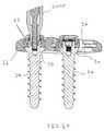
- FIG. 1is a perspective view of a bone plate system in accordance with the present invention showing a bone plate and a pair of bone anchor assemblies connected thereto;
- FIG. 2is a perspective view of one of the bone anchor assemblies of FIG. 1 showing a bone screw, cap drive member, and a resilient locking cap of the bone anchor assembly;
- FIG. 3is an elevational view of one of the bone anchor assemblies of FIG. 1 showing the cap drive member of the bone anchor assembly in an unlocked position;
- FIG. 4is an elevational view similar to FIG. 3 showing the cap drive member shifted to a locked position which radially expands the resilient locking cap of the bone anchor assembly;
- FIG. 5is a top plan view of the bone plate system of FIG. 1 showing one of the bone anchor assemblies received in a resilient support member in an elongated throughbore of the bone plate and the other bone anchor assembly received in a non-elongated throughbore of the bone plate;
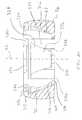
- FIG. 6is a cross-sectional view taken across line 6 - 6 in FIG. 5 showing a head portion of the bone anchor assembly received in the resilient support member with the cap drive member of the bone anchor assembly in the unlocked position;
- FIG. 7is a cross-sectional view similar to FIG. 6 showing the cap drive member shifted to the locked position which expands the locking cap and the resilient support member of the bone plate;
- FIG. 8is a partial, enlarged view of the area shown in the dashed circle of FIG. 5 showing projections of the resilient support member spaced from teeth of the bone plate before the cap drive member has been driven to the locked position;
- FIG. 9is a partial, enlarged view similar to FIG. 8 showing the projections of the support member engaged with the teeth of the bone plate after the cap drive member of the bone anchor assembly has been driven to the locked position;
- FIG. 10is a cross-sectional view taken across line 10 - 10 in FIG. 5 showing generally spherical head portions of the bone anchor assemblies received in partially spherical pockets of the resilient support member and the non-elongated throughbore;
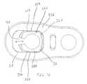
- FIG. 11is a top plan view of the bone plate system of FIG. 1 with the bone anchor assemblies removed to show an opening of the resilient support member in which one of the bone anchor assemblies is received;
- FIG. 12is a bottom plan view of the bone plate of FIG. 1 showing a generally rectangular lower opening of the elongated throughbore and a generally rectangular lower portion of the support member fit within the lower opening of the elongated throughbore;
- FIG. 13is a perspective view of the resilient support member of the bone plate system of FIG. 1 showing a split-ring configuration of the support member;
- FIG. 14is a top plan view of the support member of FIG. 13 showing the projections of the support member extending radially outward for engaging the teeth of the bone plate;
- FIG. 15is a bottom plan view of the support member of FIG. 13 showing the flange of the support member extending radially beyond the generally rectangular lower portion of the support member;
- FIG. 16is an exploded elevational view of one of the bone anchor assemblies of FIG. 1 ;
- FIG. 17is an elevational view of the bone screw of the bone anchor assembly of FIG. 16 showing the head of the bone screw having a rounded lower surface;
- FIG. 18is a top plan view of the bone screw of FIG. 17 showing a recess for receiving a driving tool
- FIG. 19is a perspective view of the bone screw of FIG. 17 showing a radially extending bearing surface of the bone screw configured to support the resilient locking cap and a threaded wall upstanding from the bearing surface;
- FIG. 20is a cross-sectional view taken across line 20 - 20 in FIG. 18 showing a central axial bore for receiving a screw retention portion of the driving tool;
- FIG. 21is an elevational view of the resilient locking cap of the bone anchor assembly of FIG. 16 showing a rounded outer surface of the resilient locking cap;
- FIG. 22is a top plan view of the locking cap of FIG. 21 showing an outer annular wall and radially extending portions of the locking cap;
- FIG. 23is a perspective view of the locking cap of FIG. 1 showing a gap spacing between ends of the locking cap;
- FIG. 24is a cross-sectional view taken across line 24 - 24 in FIG. 22 showing radially inner inclined surfaces against which the cap drive member cams;
- FIG. 25is an elevational view of the cap drive member of the bone screw of FIG. 16 showing a radially outer, inclined surface of the cap drive member configured to engage the radially inner inclined surfaces of the locking cap;
- FIG. 26is a top plan view of the cap drive member of FIG. 17 showing a central opening of the cap drive member;
- FIG. 27is a perspective view of the cap drive member of FIG. 17 showing structures of the cap drive member disposed about the central opening configured to engage a locking tool;
- FIG. 28is a cross-sectional view taken along line 28 - 28 in FIG. 26 showing an outer profile of the cap drive member
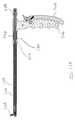
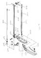
- FIG. 29is an elevational view of an inserter tool configured to be used to insert the bone plate of FIG. 1 during surgery;
- FIG. 29Ais a top plan view of the inserter tool of FIG. 29 showing the bone plate in a generally parallel orientation relative to a shaft of the inserter tool;
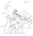
- FIG. 30is an enlarged partial view of a distal end of the inserter tool of FIG. 29 showing the distal end connected to the bone plate;
- FIG. 31is an enlarged elevational view of the distal end of the inserter tool of FIG. 29 showing a linkage between the shaft and a pivot body of the inserter tool which is connected to the bone plate;
- FIG. 32is an elevational view similar to FIG. 29 showing a lever of the tool moved toward a handle of the tool which causes the inserter tool to pivot the bone plate;
- FIG. 32Ais a top plan view of the inserter tool of FIG. 32 showing the bone plate pivoted to a generally perpendicular orientation relative to the inserter tool shaft;
- FIG. 33is an enlarged partial view of the distal end of the inserter tool of FIG. 32 showing the distal end connected to the bone plate;
- FIG. 34is an exploded schematic view of the inserter tool of FIG. 29 showing a body shaft, a pivot shaft, and a grip control shaft of the inserter tool;
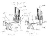
- FIG. 35Ais a cross-sectional view of the inserter tool taken across line 35 A- 35 A in FIG. 29A showing the lever in the open position and a pivot shaft of the inserter tool shifted distally;
- FIG. 35Bis a cross-sectional view of the inserter tool taken across line 35 B- 35 B in FIG. 32B showing the lever in the closed position and the pivot shaft shifted proximally with the bone plate removed for clarity;
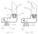
- FIG. 36is an elevational view of the distal end of the inserter tool of FIG. 29 with the bone plate removed therefrom showing a gripping portion of the inserter tool and arms of the gripping portion in a release configuration;
- FIG. 37is an elevational view similar to FIG. 36 showing the gripping portion arms in an engagement configuration
- FIGS. 38 and 39are enlarged cross-sectional views generally taken across line 35 B- 35 B in FIG. 32A showing the gripping portion arms in the release and engagement configurations;
- FIGS. 40 and 41are bottom plan views of the bone plate connected to the distal end of the inserter tool showing the gripping portion arms in the release and engagement configurations;
- FIGS. 42 and 43are views of the handle of the inserter tool showing an outer profile of the handle
- FIGS. 44-52illustrate a method of implanting the bone plate system of FIG. 1 ;
- FIG. 53is a left side elevational view of another inserter tool configured to be used to insert the bone plate of FIG. 1 during surgery;
- FIG. 54is right side perspective view of the inserter tool of FIG. 53 showing the inserter tool partially disassembled including a pivot sleeve of the inserter tool disconnected from a lever of the tool and pivoted away from a shaft of the inserter tool;
- FIG. 55is an exploded schematic view of the inserter tool of FIG. 53 showing a body shaft, the pivot sleeve, and a pivot control shaft of the inserter tool;
- FIG. 56is an enlarged right side perspective view of the inserter tool of FIG. 53 showing the pivot sleeve connected to the lever;
- FIG. 57is a cross-sectional view of the inserter tool of FIG. 53 showing a lever of the inserter tool in an open position;
- FIG. 58is a cross-sectional view similar to FIG. 57 showing the lever in a closed position
- FIGS. 59 and 60are enlarged, elevational views of different sides of the inserter tool of FIG. 53 showing arms of the body shaft which support a pivot body of the distal end of the inserter tool;
- FIG. 61is an enlarged plan view of the distal end of the inserter showing the pivot body pivoted relative to the body shaft;
- a bone plate system 10having a bone plate 12 with a bone plate member 14 and a movable resilient support member 16 .
- the support member 16may be moved along an elongated throughbore 18 of the bone plate member 14 to provide flexibility during installation of the bone plate system 10 .
- the bone plate system 10includes a pair of bone anchor assemblies 20 , 24 for securing the bone plate 12 to a pair of bones, with the bone anchor assembly 20 being driven into an opening 53 of the support member 16 and a bone anchor assembly 24 being driven into a non-elongated throughbore 22 of the bone plate member 14 (see FIG. 11 ).
- the bone anchor assemblies 20 , 24are preferably preassembled for ease of handling during surgery and can be readily driven into the support member opening 53 and bone plate throughbore 22 to secure the bone plate 12 to bones.
- the resilient support member 16may be moved within the elongated throughbore 18 to increase or decrease the distance between the support member opening 53 and the non-elongated throughbore 22 , and the resulting positions of the bone anchor assemblies 20 , 24 , in order to permit the bone anchor assemblies 20 , 24 to be driven into desired areas of the underlying bones.
- the support member 16 and the bone anchor assembly 20may be secured at a desired location along the throughbore 18 to restrict translational movement of the bone anchor assemblies 20 , 24 relative to each other, as discussed in greater detail below.
- the bone plate system 10provides enhanced flexibility during installation by allowing the position of the support member 16 within the elongated throughbore 18 to be adjusted in situ to conform to the anatomy of the patient before securing the bone plate 12 to the bones using the bone anchor assemblies 20 , 24 .
- the bone anchor assemblies 20 , 24are similar and each have a bone anchor, such as a bone screw 26 , for engaging a bone.
- the bone screw 26has a bone screw head 30 and an actuator device 32 carried thereon, as shown in FIG. 2 .
- the actuator device 32is configured to be driven to a locked position after the bone screw 26 has been seated within the support member opening 53 .
- Driving the actuator device 32 of the bone anchor assembly 20 to the locked positiontightly engages the bone anchor assembly 20 with the support member 16 .
- Driving the actuator device 32 of the bone anchor assembly 20also locks the support member 16 to the bone plate member 14 at a selected position along the elongated throughbore 18 , as discussed in greater detail below.
- driving the actuator device 32 of the bone anchor assembly 24 to its locked positiontightly engages the bone anchor assembly 24 to the plate member 14 within the non-elongated throughbore 22 .
- the actuator device 32includes a cap drive member 34 connected to the bone screw head 30 and a resilient locking cap 36 disposed on the bone screw head 30 , as shown in FIG. 2 .
- the connection between the cap drive member 34 and the bone screw head 30may be a threaded engagement so that clockwise rotation of the cap drive member 34 in direction 40 about a longitudinal axis 42 of the bone anchor assembly 20 advances the cap drive member 34 in direction 46 toward the bone screw head 30 , as shown in FIGS. 3 and 4 .
- Movement of the cap drive member 34 in direction 46 toward the bone screw head 30causes outward expansion of the locking cap 36 in directions 60 , 62 , which expands the support member 16 and secures the support member 16 and bone anchor assembly 20 at a desired position along the elongated throughbore 18 .
- the cap drive member 34has a depending wall 64 extending about a portion of the bone screw head 30 , such as screw head upstanding wall 66 .
- the depending wall 64 of the cap drive member 34is disposed radially between the bone screw wall 66 and the locking cap 36 .
- the depending wall 64 and the bone screw wall 66each have a generally tubular shape and are concentrically aligned when the cap drive member 34 is connected to the bone anchor head 30 .
- the locking cap 36has a generally annular shape extending around the cap drive member 34 when the cap drive member 34 and the locking cap 36 are connected to the bone screw head 30 .
- cap drive member depending wall 64The concentric engagement of the bone screw wall 66 , cap drive member depending wall 64 , and locking cap 36 allows the cap drive member depending wall 64 to directly transfer loading exerted on the locking cap 36 , such as loads from post-operative shifting of the vertebra, against the bone screw wall 66 without the use of thin, radially extending members as in some prior bone anchor assemblies. Further, the cap drive member depending wall 64 can directly transfer loading from the locking cap 36 to the bone screw wall 66 with substantially no deflection or other flexing of the cap drive member depending wall 64 , which increases the strength of the engagement between the bone anchor assemblies 20 , 24 and the bone plate 14 .
- the cap drive member 34 and locking cap 36have engagement surfaces, such as cam surfaces 50 , 52 , configured to engage and expand the locking cap 36 with movement of the cap drive member 34 from an unlocked to a locked position, as shown in FIGS. 6 and 7 .
- the cam surface 50is disposed on a radially outer portion 55 (see FIG. 28 ) of the cap drive member depending wall 64 and the cam surface 52 is disposed on a radially inner portion 57 (see FIG. 24 ) of the locking cap 36 so that the cam surfaces 50 , 52 engage about and radially outward from the bone screw wall 66 .
- the bone screw head 30may be substantially rigid, and positioning the cam surfaces 50 , 52 about and radially outward from the bone screw head portion 66 permits the cap drive member 34 to expand the locking cap 36 without utilizing a weakened screw head as in some prior approaches.
- cam surfaces 50 , 52 of the cap drive member 34 and locking cap 36being disposed about and radially outward from the bone screw wall 66 is that the cam surfaces 50 , 52 are positioned outside of a drive recess 71 of the bone screw head 30 , as shown in FIGS. 6 and 7 .
- the drive recess 71is generally unobstructed by the cap drive member 34 and locking cap 36 so that the size of the drive recess 71 can be relatively large without reducing the strength of the cap drive member depending wall 64 .
- the bone screw upstanding wall 66 extending about the drive recess 71can be relatively thick to further enhance the strength of the bone screw head 30 without compromising the strength of the locking cap depending wall 64 .
- the resilient support member 16may be moved in directions 48 A, 48 B along an axis 47 of the elongated throughbore 18 before the bone anchor assembly 20 is driven into the opening 53 and the cap drive member 34 shifted to the locked position.
- This adjustabilityallows a surgeon to position the support member 16 so that the opening 53 is adjacent a desired portion of an underlying bone.
- the bone plate system 10may be used to stabilize a pair of vertebrae 720 , 722 with an implant 724 having a width 804 (see FIG. 46 ).
- the support member 16may be moved in direction 48 A in order to increase the distance between the support member opening 53 and non-elongated throughbore 22 and the resulting positioning of the bone anchors 20 , 24 .
- the support member 16can be moved in direction 48 A until the support member opening 53 is located adjacent the vertebra 722 , for example, so that the bone anchor assembly 20 may be driven through the opening 53 and into an end plate of the vertebra.
- the support member 16may be moved in direction 48 B to decrease the distance between the support member opening 53 and the non-elongated throughbore 22 and the resulting distance between the bone anchor assemblies 20 , 24 .
- the bone anchor assembly 20may be driven into the support member opening 53 and the position of the support member 16 and bone anchor assembly 20 may then be locked along the throughbore 18 , as shown in FIGS. 5-7 .
- the resilient support member 16has a pair of side portions 72 , 74 on opposite sides of the opening 53 configured to be engaged by the resilient locking cap 36 .
- the plate member 14 and support member 16also have interfering portions 90 , such as support member projections 92 and plate member teeth 94 , configured to engage and limit movement of the support member 16 relative to the bone plate member 14 , as shown in FIGS. 8 and 9 .
- Expansion of the resilient support member 16shifts the support member projections 92 and plate member teeth 94 from an adjustment orientation, where there is a gap spacing 96 between the projections 92 and teeth 94 , into a locked orientation where the projections 92 and teeth 94 are engaged, as shown in FIGS. 8 and 9 .
- the engaged projections 92 and teeth 94restrict translational movement of the support member 16 and bone anchor assembly 20 received therein along the elongated throughbore 18 .
- the support member projections 92 and bone plate teeth 94can be quickly shifted from the adjustment orientation to the locked orientation to lock the position of the support member 16 and bone anchor assembly 20 simply by shifting the cap drive member 34 to the locked position after the bone screw head 30 has been seated in the opening 53 .
- This easy-to-use location locking mechanismadvantageously provides the bone anchor stability of a bone plate having static bone anchor locations as well as the installation flexibility of a bone plate having elongated throughbores. Further, the engaged projections 92 and teeth 94 may also restrict rotation of the support member 16 about the bone anchor longitudinal axis 46 within the throughbore 18 to increase the stability of the bone anchor 20 within the elongated throughbore 18 .
- the tolerances between the support member projections 92 and bone plate teeth 94produce a slight ratcheting action when the projections 92 and teeth 94 are in the adjustment orientation and the support member 16 is moved along the elongated throughbore 18 .
- the slight ratcheting actionmay be desirable in some applications to restrict the support member 16 from moving out of a desired position along the throughbore 18 before the bone anchor assembly 20 is driven into the support member opening 53 (see FIG. 48 ).
- the support member projections 92 and the bone plate teeth 94may be in clearance with one another when they are in the adjustment orientation.
- the interfering portions of the support member 16 and the bone plate member 14may have a variety of possible configurations.
- the interfering portionsmay include one or more pins located on the support member 16 and one or more corresponding recesses on the bone plate member 14 .
- the interfering portionsmay include one or more tabs of the support member 16 and one or more corresponding slots on the bone plate member 14 .
- shifting the cap drive member 34 to the locked positionshifts the partially spherical outer surface 100 of the locking cap 36 radially outward until the outer surface 100 is generally flush with a partially spherical lower surface 102 of the screw head 30 .
- the surfaces 100 , 102form a larger, partially spherical outer surface 95 of a head portion of the bone anchor assembly 20 .
- the support member 16has the partially spherical pocket surface 103 and the non-elongated throughbore 22 has a partially spherical pocket surface 120 each with a respective radius of curvature that is complimentary to the curvatures of the outer surfaces 100 , 102 with the locking caps 36 in their expanded configurations, as shown in FIG. 10 .
- the head portions 97 of the bone anchor assemblies 20 , 24thereby form a ball-and-socket connection between the bone anchor assemblies 20 , 24 and the bone plate 12 .
- the ball-and-socket connectionspermit a controlled pivoting of the bone anchor assemblies 20 , 24 to accommodate post-operative movement of the bones.
- driving the bone anchor 26 into the support member opening 53also seats the screw head lower surface 102 against a seating portion 105 of the pocket surface 103 which can be used to lag the bone plate member 14 against a bone. Further, the engagement between the bone screw head lower surface 102 and the seating portion 105 of the pocket surface 103 provides a direction connection between the bone screw 26 and the bone plate 12 . This direct connection increases the strength of the engagement between the bone screw 26 and the bone plate 12 and permits the bone screw 26 to directly transfer loading to the bone plate 12 .
- the cap drive member 34is then shifted to the locked position which expands the locking cap 36 and brings the cap outer surface 100 into engagement with an engagement portion 107 of the pocket surface 103 .
- Driving the cap drive member 34 into the locked positionfirmly engages the partially spherical outer surface 100 of the locking cap 36 with the engagement portion 107 of the pocket surface 103 .
- both the cap outer surface 100 and the head lower surface 102are frictionally engaged with the support member seating surface 103 . This frictional engagement provides controlled resistance to pivoting movement of the bone anchor assembly 20 relative to the support member 16 .
- the bone anchor assembly head portion 97has a height 99 along the bone anchor assembly longitudinal axis 42 and the locking cap partially spherical outer surface 100 has a height 101 that is approximately half the height 99 of the bone anchor assembly head portion 97 .
- the height 101could be approximately a quarter of the height 99 , approximately three-quarters of the height 99 , or another proportion although the locking cap height 101 is preferably greater than a quarter of the head portion height 99 in order to preserve a sufficiently large partially spherical lower surface 102 of the bone screw head 30 .
- the relatively large axial extent or height 101 of the locking cap outer surface 100provides a large amount of surface area of the locking cap outer surface 100 which can engage the support member pocket surface 103 . This increases the frictional engagement of the locking cap 36 with the support member 16 and limits pivoting of the bone anchor assembly 20 once the cap drive member 34 has been shifted to the locked position.
- the partially spherical seating surfaces 103extends along the locking cap outer surfaces 100 substantially the entire length of the outer surface 100 along the longitudinal axis 42 of the bone anchor assembly 20 .
- the frictional engagement between the locking cap outer surface 100 and the support member seating surface 103can be maximized.
- the partially spherical seating surface 120 of the non-elongated throughbore 22is similar to the support member seating surface 103 and provides similar advantages in terms of engagement and controlled pivoting between the bone anchor assembly 24 and the plate member 14 .
- the materials of the bone screw 26 , locking cap 36 , and bone plate member 14may be selected, in part, to provide a desired amount of frictional engagement between the bone anchor assembly 20 and the support member 16 which controls pivoting of the bone anchor 20 .
- the surface texture of the surfaces 100 , 102 , 103 , and 120may also be configured to provide a desired amount of frictional engagement therebetween and resulting resistance to pivoting of the bone anchor assemblies 20 , 24 relative to the bone plate 12 .
- the roughness of one or more of the surfaces 100 , 102 , 103 , and 120can be increased, such as by blasting, in order to increase the frictional engagement between the support member 16 and the bone anchor assembly 20 and increase resistance to pivoting of the bone anchor assembly 20 .
- the support member 16 and throughbore 18have cooperating features configured to limit rotation of the support member 16 and generally restrict the support member 16 to movement along the axis 47 of the elongated throughbore 18 .
- the throughbore 18has a narrow section 150 near a bottom surface 152 of the bone plate member 14 .
- the narrow section 150includes flat guide surfaces 154 , 156 on opposite sides have the throughbore 18 extending along the axis 46 of the throughbore 18 .
- the support member 16has a narrow lower portion 160 configured to fit within the throughbore narrow section 150 between the guide surfaces 154 , 156 .
- the support member lower portion 160has a pair of lower walls 162 , 164 configured to abut the guide surfaces 154 , 156 , as shown in FIGS. 12 and 15 .
- the plate member lower walls 162 , 164engage the support member guide surfaces 154 , 156 and resist rotary movement of the support member 16 within the throughbore 18 . This further increases the stability of the construct of the bone plate member 14 , support member 16 , and bone anchor assembly 20 .
- the support member 16has a c-ring shape including a pair of opposed ends 180 , 182 separated by a gap 184 .
- the gap 184permits the ends 180 , 182 to move apart with radial expansion of the locking cap 36 due to shifting of the cap drive member 34 to the locked position (see FIGS. 6 and 7 ).
- the gap 184also permits the support member 16 to be compressed, with ends 180 , 182 shifting toward each other, during insertion of the support member 16 through an enlarged upper section 186 of the throughbore 18 adjacent an upper surface 187 of the plate member 14 (see FIGS. 10 and 11 ).
- the compressed support member 16may be advanced into the throughbore 18 until a lower surface 200 of a flange 202 of the support member 16 contacts a lower support surface 204 of a channel 206 of the plate member 14 , as shown in FIG. 6 .
- the compressed support member 16may then be released to permit the ends 180 , 182 to expand apart and the flange 202 to shift outward into the channel 206 .
- the resilient support member 16is retained in the elongated throughbore 18 and may be shifted therealong as discussed above.
- the engagement between the support member flange 202 and the plate member channel 206permits the bone anchor 20 to lag the bone plate 12 against a bone by seating the bone anchor 30 within the support member opening 53 . Further, the engagement between the support member flange 202 and the plate member channel 206 transfers axial loading between the bone anchor 20 and bone plate 12 and restricts pull-through of the bone anchor assembly 20 out of the elongated throughbore 18 .
- the channel 206includes sections 210 , 212 on opposite sides of the throughbore 18 (see FIGS. 6 and 7 ) sized to receive corresponding portions 214 , 216 of the support member flange 202 (see FIG. 14 ).
- the support member flange 202has outer surfaces 224 , 226 and the channel sections 210 , 212 have guide surfaces 228 , 230 which guide the support member 16 along the throughbore 18 , as shown in FIG. 6 .
- the support member 16has a body 220 with a width of 222 selected to permit the projections 92 a , 92 b to be in the adjustment orientation relative to the bone plate teeth 94 a , 94 b when the support member 16 is in the unexpanded configuration.
- the width 222also provides a small amount of clearance between the flange outer surfaces 224 , 226 and the channel guide surfaces 228 , 230 which permits the support member 16 to be moved longitudinally within the elongated throughbore 18 .
- the narrow section 150 of the support member 16may have a width 240 between the support member lower walls 162 , 164 which provides slight gaps 225 , 227 between the walls 162 , 164 and the plate member guide surfaces 154 , 156 . These gaps limit interference between the walls 162 , 164 when the support member 16 is in the unexpanded and expanded configurations, although the gaps 162 , 164 are smaller when the support member has been expanded.
- Limiting interference between the support member lower walls 162 , 164 and the plate member guide surfaces 154 , 156may be desirable to ensure that the support member projections 92 A, 92 B fully engage the plate member teeth 94 A, 94 B despite variation in tolerances of the plate member 14 , support member 16 , and bone anchor assembly 20 during manufacturing.
- the bone screw head 30has a partially spherical lower surface 102 , a shoulder bearing surface 252 extending inward from the lower surface 102 , and the wall 66 upstanding from the shoulder bearing surface 252 .
- the upstanding wall 66has a connection structure, such as threads 264 , for connecting to the cap drive member 34 .
- the upstanding wall 66also includes the drive structure 71 for receiving a driving tool 2000 , as shown in FIG. 48 .
- the drive structure 71includes a drive recess 280 for receiving a distal end of the driving tool, such as a socket, a hex socket, or a Phillips recess.
- the drive recess 280may be a T20 Torx drive to provide a firm engagement between the driving tool 2000 and the bone screw 26 during insertion and driving of the bone anchor assemblies 20 , 24 .
- the bone screw head 30may also have a retention structure 282 configured to engage a retention portion of the driver tool 2000 and maintain the bone anchor assembly 20 on the driving tool 2000 until the bone anchor assembly 20 has been driven into bone.
- the retention structure 282has threads 284 configured to engage threads of an internal retention shaft 2004 (see FIG. 48 ) of the driving tool 2000 .
- the locking cap 36has an outer wall 310 with a split-ring configuration and engagement members 312 extending inwardly from the outer wall 310 .
- the engagement members 312have retention tips 314 sized to fit within a groove 270 extending around a base of the annular wall 66 (see FIGS. 17 and 20 ).
- the retention tips 314have upper stop surfaces 316 that are positioned below a stop surface 272 of the bone screw groove 270 when the locking cap 36 has been assembled onto the screw head 30 .
- the surfaces 272 , 316are in axial overlapping relation such that the surfaces 272 , 316 contact and restrict removal of the locking cap 36 in direction 380 (see FIG. 16 ) once the locking cap 36 has been assembled onto the bone screw head 30 .
- the locking cap engagement members 312are generally wedge shaped and taper radially inward from an upper portion 313 adjacent the cap drive member 34 toward a lower portion 315 adjacent the shoulder bearing surface 252 of the bone screw head 30 , as shown in FIG. 24 .
- the locking cap 36has cutouts 320 between each of the cam members 312 that define the general wedge shape of each engagement member 312 and increase the flexibility of the locking cap 36 , as shown in FIG. 22 .
- the locking cap engagement surface 52includes a cam surface 322 on each of the engagement members 312 that extends obliquely relative to the bone anchor longitudinal axis 46 .
- the cam surface 322may extend a majority of the height of the locking cap 36 along the anchor axis 46 and taper from a wider upper portion 324 to a narrow lower portion 326 to produce a relatively large amount of area for the cam surface 322 of each engagement member 312 . This increases the overall cam surface area of the locking cap 36 and improves the ease with which the locking cap 32 may expand the locking cap 36 .
- the tapered shape of the cam surface 322provides a surface for contacting the cap drive member engagement surface 50 while preserving the general wedge-shape of the engagement members 312 which improves the flexibility of the locking cap 36 .
- the cam surface 322also extends radially inward toward the bone screw upstanding wall 66 which permits the cap drive member engagement surface 50 to engage the cam surfaces 322 even as the locking cap 36 expands away from the upstanding wall 66 as the cap drive member 34 reaches its locked position.
- the cap drive member 34has an upper drive portion 401 with a through opening, such as an upper locking recess 400 , sized to receive both the driving tool 2000 (see FIG. 49 ) and a distal end 3000 of a final tightener 3002 (see FIG. 51 ).
- the cap drive member 34has a locking structure 402 configured to engage the final tightener 3002 .
- the locking structure 402is a T30 Torx socket, which is larger than a T20 Torx socket of the bone screw drive structure 71 .
- the cap drive member 34thereby permits a first tool to be used to drive the bone anchor assemblies 20 , 24 into bones, and a different, second tool to be used to perform final locking of the bone anchor assemblies 20 , 24 to the bone plate 12 .
- the cap drive member 34has a lower end portion 403 and the engagement surface 50 includes a cam surface 404 that extends about the lower end portion 403 inwardly and obliquely relative to the bone anchor longitudinal axis 46 .
- the lower end portion 403 of the cap drive member 34thereby acts as a wedge to expand the locking cap 36 as the cap drive member 34 is driven to the locked position.
- the cam surface 404is disposed radially outward on the cap drive member 34 and has a large surface area due to the diameter of the cap drive member 34 .
- the large surface areas of the cap drive member cam surface 404 and locking cap cam surfaces 322improve force transfer between the cap drive member 34 and the locking cap 36 . Further, the large surface areas of the cap drive member cam surface 404 and locking cap cam surfaces 322 increase the frictional engagement between the cap drive member 34 and locking cap 36 which restricts movement of the cap drive member 34 away from the locked position.
- the cam surface 404is annular and continuous about the cap drive member 34 which permits the cam surface 404 to remain engaged with the cam surfaces 322 of the locking cap 36 as the drive member 34 is rotatably driven to the locked position.
- the cap drive member 34 and locking cap 36are generally assembled in a direction 250 onto the screw head 30 along the longitudinal axis 42 of the bone anchor assembly 20 , as shown in FIG. 16 .
- the locking cap 36is positioned on the shoulder bearing surface 252 (see FIG. 19 ) of the screw head 30 .
- Positioning the locking cap 36 onto the bearing surface 252 of the bone screw head 30may include expanding the locking cap 36 by moving ends 300 , 302 thereof apart to enlarge a gap spacing 304 therebetween (see FIG. 22 ).
- the locking cap 36may then be moved axially downwardly onto the bone screw head 30 with the upstanding wall 66 passing into a lower opening 306 of the locking cap 36 (see FIG. 24 ).
- the lower end portion 403 of the cap drive member 34is advanced into a central opening 354 (see FIG. 23 ) of the locking cap 36 .
- the locking cap 36has retention ribs 372 disposed above the engagement members 312 with guide surfaces 356 thereon. Advancing the cap drive member lower portion 403 into the locking cap central opening 354 brings the cap drive member cam surface 404 into contact with tapered guide surfaces 356 of the locking cap retention ribs 372 . Continued axial movement of the cap drive member 34 toward the bone screw head 30 causes the cap drive member cam surface 404 to bear against the locking cap guide surfaces 356 . This partially expands the locking cap 36 and permits a shoulder 470 of the cap drive member 34 (see FIG. 28 ) to travel axially beyond the retention ribs 372 of the locking cap 36 .
- the shoulder 470has a flat annular stop surface 472 that is positioned below stop surfaces 376 on the undersides of the retention ribs 372 of the locking cap 36 , as shown in FIGS. 24 and 28 .
- the stop surfaces 376 , 472are in an axially overlapping and confronting orientation which restricts removal of the cap drive member 34 from within the locking cap 36 in direction 380 (see FIG. 6 ).
- stop surfaces 272 , 316 and 376 , 472 of the bone anchor 26 , cap drive member 34 , and locking cap 36maintain the cap drive member 34 and locking cap 36 on the bone screw head 30 and keep the bone anchors 20 , 24 in the preassembled configuration.
- the components of the bone plate system 10may be made of biocompatible materials, such as stainless steels, titanium or titanium alloys, or other metals or alloys.
- the components of the bone plate 10may also be made of one or more polymers, such as polyether ether ketone (PEEK).
- an inserter tool 500is provided for inserting the bone plate 12 into a confined surgical environment and positioning the bone plate 12 near one or more bones.
- the inserter tool 500has a distal end portion 502 configured to releasably connect to the bone plate 12 and a proximal end portion 504 with a grippable handle 506 .
- the inserter tool 500has a pivot mechanism 507 configured to selectively pivot the bone plate 12 , the pivot mechanism 507 having an insertion configuration where a longitudinal axis 530 the bone plate 12 is oriented generally parallel to a longitudinal axis 532 of a shaft 509 of the inserter tool 500 (see FIGS.
- the inserter tool distal end portion 502 and the plate member 12 connected theretoare relatively compact, particularly in a lateral direction transverse to the shaft axis 532 , and can be advanced through a surgical channel having a smaller cross-section than if the bone plate 12 was extending perpendicular to the shaft axis 532 .
- the relatively compact configuration of the tool distal end portion 502 and plate member 12can be seen, for example, by comparing a leading end width 531 of the distal end portion 502 and plate member 12 when the pivot mechanism 507 is in the insertion configuration (see FIG. 29A ) to a leading end width 533 when the pivot mechanism 507 is in the positioning configuration (see FIG. 32A ). Because the leading end width 531 is smaller than the width 533 , the inserter tool distal end portion 502 and plate member 12 may be advanced through a smaller working channel when the pivot mechanism 507 is in the insertion configuration than if the pivot mechanism 507 were in the placement configuration. Thus, the pivot mechanism 507 enables the inserter tool 500 to be used in more tightly confined environments and provides a significant improvement over inserter tools that can grasp an implant in only a perpendicular orientation.
- the pivot mechanism 507can be shifted and reconfigured to the positioning configuration where the bone plate 12 is generally perpendicular to the shaft 509 , as shown in FIGS. 32 and 32A .
- the handle 506can be manipulated to move the bone plate 12 within the surgical site and position the bone plate 12 at a desired location on one or more bones (see FIGS. 45 and 46 ).
- the inserter tool 500provides improved ability to advance elongate implants, such as the bone plate 12 , through a small working channel and then pivot the implant relative to the inserter tool 500 and permit placement of the implant on one or more bones.
- the inserter tool shaft 509includes an outer body shaft 522 , an intermediate pivot sleeve 520 , and an inner grip control shaft 574 .
- the pivot mechanism 507includes the handle 508 , the pivot sleeve 520 , and a pivot body 524 connected to a distal end of the body shaft 522 . Moving or compressing the lever 508 toward the handle to a closed position causes the pivot sleeve 520 to slide proximally within the body shaft 522 and pivot the pivot body 524 approximately 90 degrees about a pivot axis 526 , as shown in FIGS. 29 , 32 , 35 A, and 35 B.
- the bone plate 12is connected to the pivot body 524 , such that pivoting of the pivot body 524 due to compressing the lever 508 causes the bone plate 12 to pivot relative to the inserter tool shaft 509 . More specifically, compressing the lever 508 causes the bone plate 12 to move from an insertion orientation where a longitudinal axis 530 of the bone plate 12 is generally parallel with a longitudinal axis 532 of the shaft 509 to a positioning orientation where the bone plate longitudinal axis 530 is generally perpendicular to the shaft axis 532 .
- the inserter tool 500has a latch 534 with a hook 536 which may be pivoted to an engaged position where the hook 536 engages a tooth 538 of the handle 506 .
- the latch 534may be biased to the engagement position by a spring to restrict the latch 534 from being inadvertently disengaged.
- the inserter tool 500includes a spring 540 arranged to bias the pivot sleeve 520 toward the distal end portion 502 of the inserter tool 500 .
- Moving the lever 508 toward the handle 506overcomes the bias force from the spring 540 and shifts the sleeve 520 back toward the proximal end portion 504 .
- the outer body 522includes a pair of pins 542 inserted in holes 544 of the body 522 (see FIG. 34 ) to support a spring support 546 within the body 522 and prevent the support 544 from traveling in direction 548 .
- a second spring support 550fixed to the pivot sleeve 520 and housed within the body shaft 522 when the inserter tool 500 is assembled. Compressing the handle 508 causes the pivot sleeve 520 to move in direction 548 toward the proximal end portion 504 , which moves the spring support 550 mounted on the pivot sleeve 520 in direction 548 and compresses the spring 540 between the supports 546 , 550 . Releasing the handle 508 permits the spring 540 to expand and shift the pivot sleeve 520 in direction 556 back toward the distal end portion 502 .
- the inserter tool 500has a gripping device 570 that allows the inserter tool 500 to releasingly engage the bone plate 12 .
- the gripping device 570includes a grip control member, such as knob 572 , and a gripping portion 580 that is configured to engage the bone plate 12 .
- the gripping device 570includes the grip control shaft 574 disposed within the pivot sleeve 520 and the knob 572 is threadingly engaged with the grip control shaft 574 . Rotation of the knob 572 produces longitudinal movement of the grip control shaft 574 within the pivot shaft 520 and manipulates the configuration of the gripping portion 580 .
- the gripping portion 580may have a plate engagement arm 582 and a fixed arm 584 sized to fit into a slot 586 of the plate member 14 (see FIGS. 11 , 40 , and 41 ).
- the arm 582is operably coupled to the grip control shaft 574 by an arm linkage 590 .
- the arm linkage 590has one end connected to the grip control shaft 574 by a pin 592 and an opposite end connected to the arm 582 by a ball 594 and socket 596 connection, as shown in FIGS. 38 and 39 .
- the handle 506may have a recessed area 620 sized to provide clearance for the lever 508 and a lever pivot pin 622 for connecting the lever 508 to the handle 506 .
- a transmission end 624 of the lever 508may be connected to a lever bolt 626 mounted on the intermediate pivot shaft 620 , as shown in FIGS. 29 and 34 .
- the transmission end 624 of the lever 508has a slightly elongated opening 630 that is sized to permit the lever bolt 626 to travel along the opening 630 .
- the slight elongation of the opening 630may be desirable to accommodate the linear movement of the lever bolt 626 and the rotational, pivoting movement of the transmission end 624 of the lever 508 .
- the components of the inserter tool 500may be made of various materials that preferably can be sterilized to permit cleaning of the inserter tool 500 .
- the componentsare made of various metals and alloys, such as stainless steel.
- FIGS. 44-52a method of installing the bone plate system 12 including using the inserter tool 500 is shown.
- the distal end portion 502 of the inserter tool 500is connected to the bone plate 12 and the implant pivot lever 508 of the inserter tool 500 is moved to the open position away from the handle 506 to orient the bone plate 12 in the insertion orientation, as shown in FIG. 44 .
- the inserter tool 500 and connected bone plate 12are positioned in a generally vertical orientation above a working channel 700 formed by a retractor 702 .
- the inserter tool 500is then moved downward in direction 710 to advance the distal end portion 502 and the bone plate 12 connected thereto into the working channel 700 until an end 712 of the bone plate 12 is adjacent a surgical site 714 .
- the surgical site 714is adjacent a pair of vertebrae 720 , 722 and an implant 724 therebetween (see FIG. 46 ).
- the implant lever 508is moved toward the handle 506 to pivot the bone plate 12 and move the bone plate 12 from a generally parallel orientation relative to the vertebrae 720 , 722 into a generally perpendicular orientation, as shown in FIGS. 45 and 46 .
- the retractor 702has blades with distal ends 715 that can be angled to extend generally obliquely relative to the working channel 700 . This retracts the tissues adjacent the surgical site and provides room for pivoting of the bone plate 12 while maintaining a generally narrow working channel 700 .
- a centering sleeve 800is then advanced through the working channel 700 and connected to the static throughbore 22 before a temporary fixation pin 802 is advanced down a cannula of the centering sleeve 800 and used to temporarily fix the bone plate 12 to the vertebrae 720 .
- the inserter tool 500may then be disconnected from the bone plate 12 and removed from the working channel 700 .
- a second centering sleeve 810is subsequently advanced through the working channel 700 to connect a distal end portion 811 of the centering sleeve 810 to the support member 16 , as shown in FIG. 47 .
- the centering sleeve 810has a proximal portion 813 that may be manipulated by the surgeon to cause movement of the distal end portion 811 and support member 16 connected thereto. More specifically, the distal end portion 811 of the second centering sleeve 810 may be moved in direction 812 A or 812 B to move the support member 16 in direction 48 A or 48 B along axis 47 of the elongate throughbore 18 (see FIG. 11 ).
- the centering sleeve 810preferably has a length that positions the proximal end portion 813 outside of the working channel 700 while the distal end portion 811 is connected to the support member 16 to improve the ease of manipulation of the position of the support member 16 .
- the second centering sleeve 810may be used to adjust the position of the support member 16 along the elongated throughbore 18 from outside of the working channel 700 and adapt the bone plate 12 to the anatomy of the patient.
- the opening 53 of the support member 16may not be aligned with of the vertebrae 722 when the bone plate 12 is initially pivoted to the positioning orientation shown in FIG. 46 .
- the centering sleeve 810can then be moved in direction 812 A to move the support member 16 in direction 48 A and position the support member opening 53 above the vertebrae 722 .
- the second centering sleeve 810may be removed from the working channel 700 and the drive tool 2000 connected to the bone anchor assembly 20 .
- Connecting the driving tool 2000 to the bone anchor assembly 20includes advancing a drive tip 2002 of the driving tool 2000 through the opening 400 of the cap drive member 34 and into engagement with the drive recess 280 (see FIGS. 18 and 26 ).
- Connecting the driving tool 2000 to the bone anchor assembly 20may also include connecting the retention shaft 2004 of the tool 2000 with retention threads 284 of the bone screw 46 , as shown in FIG. 48 .
- the driving tool 2000with the bone anchor assembly 20 connected thereto, can then be advanced through the working channel 700 and to advance a shank 725 of the bone screw 26 into the support member opening 53 . (It is noted that vertebrae 720 , 722 and implant 724 are removed from FIGS. 48-52 for clarity purposes.) The driving tool 2000 is then used to drive the bone anchor 26 into the underlying vertebrae 722 , as shown in FIG. 49 .
- the drive tool 2000is used to drive the bone anchor assembly 24 into the fixed throughbore 22 using a similar approach taken with respect to bone anchor 20 , as shown in FIGS. 49 and 50 .
- a final tightener 3002is advanced into the opening 400 of the cap drive member 34 of the bone anchor assembly 24 (see FIG. 26 ) and turned in direction 737 to shift the cap drive member 34 to the locked position.
- Turning of the final tightener 3002 and the resulting movement of the cap drive member 34 toward its locked positioncauses the cap drive member 34 to expand the locking cap 36 . This tightly engages the locking cap 36 with the seating surface 120 of the throughbore 22 .
- the locking tool 3000is then advanced into the opening 400 of the cap drive member 34 of the bone anchor assembly 20 and turned to move the cap drive member 34 toward the locked position.
- the cap drive member 34is threadingly engaged with the bone screw head 30 , shifting the cap drive member 34 to the locked position tightly engages the cap drive member 34 to the head 30 as well as the locking cap 36 therebetween.
- the bone anchor assembly 20is firmly engaged with the support member 16 which is in turn firmly engaged to the plate member 14 at the desired location along the throughbore 18 .
- an inserter tool 1000is provided for positioning the bone plate 12 near one or more bones.
- the inserter tool 1000is substantially similar to the inserter tool 500 described above such that the differences between the inserter tools 500 , 1000 will be highlighted.
- One difference between the inserter tools 500 , 1000is that the inserter tool 1000 has components that can be partially disassembled and pivoted generally about an axis 1002 at a distal end 1004 of the inserter tool 1000 , as shown in FIG. 54 .
- the ability to partially disassemble and pivot the components of the inserter tool 1000allows the inserter tool 1000 to be cleaned without complete disassembly of the tool 1000 .
- the inserter tool 1000has an outer body shaft 1010 and a partial pivot sleeve 1012 for controlling pivoting of a pivot body 1014 .
- the distal end of the pivot sleeve 1012is connected to the pivot body 1014 at a pin 1030 so that translational movement of the pivot sleeve 1012 produces pivoting of the pivot body 1014 .
- the inserter tool 1000has a lever 1016 connected to the pivot sleeve 1012 for controlling pivoting of a pivot body 1014 at the distal end 1004 of the inserter tool 1000 .
- a spring 1019may bias the handle 1018 toward an open position to limit unintentional pivoting of the pivot body 1014 and bone plate 12 connected thereto.
- the lever 1016is connected to the handle 1018 by a pin 1060 received within a slot 1062 of the handle 1018 (see FIGS. 55 , 57 ).
- the lever 1016has a transmission end 1070 with a recess 1072 sized to receive a tab 1074 of the pivot sleeve 1012 , as shown in FIG. 56 .
- the tab 1074 of the pivot sleeve 1012rides in the recess 1072 during back and forth movement of the pivot sleeve 1012 .
- the lever 1016can be shifted in direction 1064 (see FIG.
- a proximal end 1073 of the pivot sleeve 1012can be pivoted in direction 1075 away from the pivot body 1014 , as shown in FIG. 54 . Pivoting the pivot sleeve 1012 in direction 1075 moves the pivot sleeve 1012 about the pin 1030 which connects the pivot sleeve 1012 to the pivot body 1014 .
- the inserter tool 1000has a grip control shaft 1050 and a grip adjustment member 1090 engaged with threads 1092 of the grip control shaft 1050 .
- the grip adjustment member 1090is captured by the threads 1092 between an enlarged knob 1094 of the grip control shaft 1050 and a collar 1096 of the body shaft 1010 .
- the grip adjustment member 1090is turned clockwise or counterclockwise to produce proximal or distal longitudinal movement of the grip control shaft 1050 by way of the engagement between internal threads of the grip adjustment member 1090 and the threads 1092 on the grip control shaft 1050 .
- the knob 1094is turned ninety degrees clockwise to rotate a foot 1095 of the grip control shaft 1050 into a recess 1097 of the pivot body 1014 (see FIGS. 55 and 57 ).
- the grip adjustment member 1090is then turned to produce longitudinal movement of the grip control shaft 1050 toward the proximal end of the inserter tool 1000 until the threads 1092 of the grip control shaft 1050 disengage the internal threads of the grip adjustment member 1090 .
- the knob 1094is grasped and pulled in direction 1099 (see FIG. 54 ) to withdraw the grip control shaft 1050 from within the outer body shaft 1010 .
- the pivot sleeve 1012is pivoted away from the outer body shaft 1010 and the grip control shaft 1050 has been withdrawn from the outer body shaft 101 . Because both the pivot sleeve 1012 and grip control shaft 1050 are separated from the body shaft 1010 , the surfaces of the body shaft 1010 , pivot sleeve 1012 , and grip control shaft 1050 may be easily accessed and cleaned. Further, as shown in FIG. 55 , the body shaft 1010 has a generally C-shaped cross section with an opening 1100 along one side thereof and the pivot shaft 1012 has a generally U-shaped cross section with an opening 1102 along one side thereof. The cross sections of the body shaft 1010 and the pivot shaft 1012 provide ready access to the internal surfaces of the body shaft 1010 and the pivot shaft 1012 so that the internal surfaces may be easily cleaned.
Landscapes
- Health & Medical Sciences (AREA)
- Orthopedic Medicine & Surgery (AREA)
- Life Sciences & Earth Sciences (AREA)
- Surgery (AREA)
- Engineering & Computer Science (AREA)
- Biomedical Technology (AREA)
- Neurology (AREA)
- General Health & Medical Sciences (AREA)
- Veterinary Medicine (AREA)
- Heart & Thoracic Surgery (AREA)
- Public Health (AREA)
- Animal Behavior & Ethology (AREA)
- Molecular Biology (AREA)
- Medical Informatics (AREA)
- Nuclear Medicine, Radiotherapy & Molecular Imaging (AREA)
- Cardiology (AREA)
- Oral & Maxillofacial Surgery (AREA)
- Transplantation (AREA)
- Vascular Medicine (AREA)
- Surgical Instruments (AREA)
- Prostheses (AREA)
Abstract
Description
Claims (22)
Priority Applications (4)
| Application Number | Priority Date | Filing Date | Title |
|---|---|---|---|
| US13/725,420US9198769B2 (en) | 2011-12-23 | 2012-12-21 | Bone anchor assembly, bone plate system, and method |
| US14/954,179US10159514B2 (en) | 2011-12-23 | 2015-11-30 | Method of implanting a bone plate |
| US16/229,873US10980575B2 (en) | 2011-12-23 | 2018-12-21 | Instrument for inserting a spinal device |
| US17/193,763US11696786B2 (en) | 2011-12-23 | 2021-03-05 | Instrument for inserting a spinal device |
Applications Claiming Priority (2)
| Application Number | Priority Date | Filing Date | Title |
|---|---|---|---|
| US201161580055P | 2011-12-23 | 2011-12-23 | |
| US13/725,420US9198769B2 (en) | 2011-12-23 | 2012-12-21 | Bone anchor assembly, bone plate system, and method |
Related Child Applications (1)
| Application Number | Title | Priority Date | Filing Date |
|---|---|---|---|
| US14/954,179ContinuationUS10159514B2 (en) | 2011-12-23 | 2015-11-30 | Method of implanting a bone plate |
Publications (2)
| Publication Number | Publication Date |
|---|---|
| US20130190825A1 US20130190825A1 (en) | 2013-07-25 |
| US9198769B2true US9198769B2 (en) | 2015-12-01 |
Family
ID=48797836
Family Applications (5)
| Application Number | Title | Priority Date | Filing Date |
|---|---|---|---|
| US13/725,420Active2033-08-18US9198769B2 (en) | 2011-12-23 | 2012-12-21 | Bone anchor assembly, bone plate system, and method |
| US13/725,322Active2033-08-27US9241807B2 (en) | 2011-12-23 | 2012-12-21 | Systems and methods for inserting a spinal device |
| US14/954,179Active2033-05-13US10159514B2 (en) | 2011-12-23 | 2015-11-30 | Method of implanting a bone plate |
| US16/229,873Active2033-07-08US10980575B2 (en) | 2011-12-23 | 2018-12-21 | Instrument for inserting a spinal device |
| US17/193,763Active2033-10-12US11696786B2 (en) | 2011-12-23 | 2021-03-05 | Instrument for inserting a spinal device |
Family Applications After (4)
| Application Number | Title | Priority Date | Filing Date |
|---|---|---|---|
| US13/725,322Active2033-08-27US9241807B2 (en) | 2011-12-23 | 2012-12-21 | Systems and methods for inserting a spinal device |
| US14/954,179Active2033-05-13US10159514B2 (en) | 2011-12-23 | 2015-11-30 | Method of implanting a bone plate |
| US16/229,873Active2033-07-08US10980575B2 (en) | 2011-12-23 | 2018-12-21 | Instrument for inserting a spinal device |
| US17/193,763Active2033-10-12US11696786B2 (en) | 2011-12-23 | 2021-03-05 | Instrument for inserting a spinal device |
Country Status (1)
| Country | Link |
|---|---|
| US (5) | US9198769B2 (en) |
Cited By (20)
| Publication number | Priority date | Publication date | Assignee | Title |
|---|---|---|---|---|
| US20150320466A1 (en)* | 2014-05-08 | 2015-11-12 | Titan Spine, Llc | Implant fixation assemblies having a screw and c-shaped fixation collar |
| US20160030098A1 (en)* | 2013-03-13 | 2016-02-04 | Paragon 28, Inc. | Force distribution implant, assembly and kit |
| US20160045231A1 (en)* | 2014-08-14 | 2016-02-18 | FloSpine LLC | Interspinous fusion device |
| US20160341245A1 (en)* | 2014-12-05 | 2016-11-24 | Black & Decker Inc. | Swivel hanger system |
| US10004608B2 (en) | 2016-02-26 | 2018-06-26 | K2M, Inc. | Insertion instrument for expandable spinal implants |
| US20180283443A1 (en)* | 2014-12-05 | 2018-10-04 | Black & Decker Inc. | Swivel hanger |
| US10159514B2 (en) | 2011-12-23 | 2018-12-25 | Pioneer Surgical Technology, Inc. | Method of implanting a bone plate |
| US10206722B2 (en) | 2008-04-25 | 2019-02-19 | Pioneer Surgical Technology, Inc. | Bone plate system |
| US10932833B2 (en) | 2015-03-03 | 2021-03-02 | Pioneer Surgical Technology, Inc. | Bone compression device and method |
| USRE48719E1 (en) | 2014-10-09 | 2021-09-07 | K2M, Inc. | Expandable spinal interbody spacer and method of use |
| US11298244B2 (en) | 2019-01-31 | 2022-04-12 | K2M, Inc. | Interbody implants and instrumentation |
| US11344346B2 (en) | 2018-06-29 | 2022-05-31 | Pioneer Surgical Technology, Inc. | Bone plate system |
| US11534307B2 (en) | 2019-09-16 | 2022-12-27 | K2M, Inc. | 3D printed cervical standalone implant |
| US20230057743A1 (en)* | 2021-08-19 | 2023-02-23 | Medline Industries, Lp | Apparatus and methods for joining bones |
| USRE49753E1 (en) | 2013-05-20 | 2023-12-12 | K2M, Inc. | Adjustable implant and insertion tool |
| US11877779B2 (en) | 2020-03-26 | 2024-01-23 | Xtant Medical Holdings, Inc. | Bone plate system |
| US12220123B2 (en) | 2021-08-19 | 2025-02-11 | Medline Industries, Lp | Apparatus and methods for joining bones |
| US12336704B2 (en) | 2023-01-13 | 2025-06-24 | Medline Industries, Lp | Apparatus and methods for joining bones |
| US12376850B2 (en) | 2023-06-22 | 2025-08-05 | Medline Industries, Lp | Surgical staple |
| US12408959B2 (en) | 2022-07-13 | 2025-09-09 | Globus Medical, Inc. | Plate inserter system and method |
Families Citing this family (42)
| Publication number | Priority date | Publication date | Assignee | Title |
|---|---|---|---|---|
| US9750545B2 (en)* | 2009-03-27 | 2017-09-05 | Globus Medical, Inc. | Devices and methods for inserting a vertebral fixation member |
| US10779957B2 (en) | 2010-09-03 | 2020-09-22 | Globus Medical, Inc. | Expandable fusion device and method of installation thereof |
| US10842644B2 (en) | 2010-09-03 | 2020-11-24 | Globus Medical, Inc. | Expandable fusion device and method of installation thereof |
| US11446162B2 (en) | 2010-09-03 | 2022-09-20 | Globus Medical, Inc. | Expandable fusion device and method of installation thereof |
| US10709573B2 (en) | 2010-09-03 | 2020-07-14 | Globus Medical Inc. | Expandable fusion device and method of installation thereof |
| US10758367B2 (en)* | 2010-09-03 | 2020-09-01 | Globus Medical Inc. | Expandable fusion device and method of installation thereof |
| US10869768B2 (en) | 2010-09-03 | 2020-12-22 | Globus Medical Inc. | Expandable fusion device and method of installation thereof |
| US10835387B2 (en) | 2010-09-03 | 2020-11-17 | Globus Medical Inc. | Expandable fusion device and method of installation thereof |
| US11793654B2 (en) | 2010-09-03 | 2023-10-24 | Globus Medical, Inc. | Expandable fusion device and method of installation thereof |
| US8940030B1 (en) | 2011-01-28 | 2015-01-27 | Nuvasive, Inc. | Spinal fixation system and related methods |
| US9351768B2 (en)* | 2011-08-26 | 2016-05-31 | Life Spine, Inc. | Bone screw retention in a spinal implant |
| US11123117B1 (en)* | 2011-11-01 | 2021-09-21 | Nuvasive, Inc. | Surgical fixation system and related methods |
| EP2623058A3 (en)* | 2012-02-06 | 2013-09-11 | Crcaholic S.A. | Fixing device and tool for surgical holding systems |
| GB201207975D0 (en)* | 2012-05-08 | 2012-06-20 | Ortho Solutions Ltd | Improvements in or relating to pelvic reconstruction |
| US9642652B2 (en)* | 2013-02-13 | 2017-05-09 | Choice Spine, Lp | Variable angle bone plate with semi-constrained articulating screw |
| US9044273B2 (en) | 2013-10-07 | 2015-06-02 | Intelligent Implant Systems, Llc | Polyaxial plate rod system and surgical procedure |
| US10143499B2 (en) | 2013-10-09 | 2018-12-04 | Stryker European Holdings I, Llc | Pivoting vertebral plate |
| EP2932929B1 (en)* | 2014-04-15 | 2017-02-08 | Biedermann Technologies GmbH & Co. KG | A screw element for use in spinal, orthopedic or trauma surgery and a system of such a screw element and a screw driver adapted thereto |
| US9855087B2 (en) | 2014-08-04 | 2018-01-02 | DePuy Synthes Products, LLC | Methods and devices for spinal screw insertion |
| EP3203920A4 (en)* | 2014-10-06 | 2018-07-04 | Implantable Design LLC | Distraction plate system |
| US10092340B2 (en) | 2014-12-09 | 2018-10-09 | Arthrex, Inc. | Fracture fixation system including locking cap and wire |
| US10105169B2 (en) | 2015-11-13 | 2018-10-23 | Leith Medical LLC | Bone fixation systems, apparatuses, and methods with anti-back-out feature |
| US10251685B2 (en)* | 2016-03-17 | 2019-04-09 | Stryker European Holdings I, Llc | Floating locking insert |
| US9987053B2 (en)* | 2016-03-29 | 2018-06-05 | Stryker European Holdings I, Llc | Surgical instruments and methods |
| EP4368128A3 (en) | 2016-09-07 | 2024-07-17 | Vertos Medical, Inc. | Percutaneous lateral recess resection methods and instruments |
| US10595907B2 (en)* | 2017-02-16 | 2020-03-24 | Rubicon Spine Llc | Polyaxial pedicle screw |
| EP3629960B1 (en)* | 2017-05-22 | 2024-10-09 | McGinley Engineered Solutions, LLC | Variable angle orthopedic fasteners for fixation of an orthopedic implant |
| US11439451B2 (en) | 2017-06-23 | 2022-09-13 | Orthopediatrics Corp. | Insertion apparatus for an intramedullary nail |
| US10433883B2 (en) | 2017-06-27 | 2019-10-08 | Medos International Sarl | Spinal screw insertion devices and methods |
| WO2019051260A1 (en) | 2017-09-08 | 2019-03-14 | Pioneer Surgical Technology, Inc. | Intervertebral implants, instruments, and methods |
| USD907771S1 (en) | 2017-10-09 | 2021-01-12 | Pioneer Surgical Technology, Inc. | Intervertebral implant |
| USD894385S1 (en) | 2017-10-27 | 2020-08-25 | Orthopediatrics Corp. | Orthopedic tool |
| US10779872B2 (en)* | 2017-11-02 | 2020-09-22 | Medos International Sarl | Bone anchor insertion instruments and methods |
| JP6704033B2 (en)* | 2017-11-07 | 2020-06-03 | グローバス メディカル インコーポレイティッド | Expandable fusion device and method of mounting the same |
| MX2022004471A (en)* | 2019-10-14 | 2022-08-16 | Leith Medical LLC | A BONE FIXATION SYSTEM WITH FASTENERS AND A REMOVAL TOOL TO DECOUPLATE FROM THE FASTENERS. |
| CA3157932A1 (en) | 2019-10-14 | 2021-04-22 | Leith Medical, LLC | Apparatus for stablization of a bone fracture site |
| US11129627B2 (en) | 2019-10-30 | 2021-09-28 | Globus Medical, Inc. | Method and apparatus for inserting a bone plate |
| US11871925B2 (en)* | 2020-07-28 | 2024-01-16 | Cilag Gmbh International | Surgical instruments with dual spherical articulation joint arrangements |
| CN112451076B (en)* | 2020-12-08 | 2022-05-13 | 精彩人生(湖北)再生医学科技有限公司 | Fracture connector made of bioactive glass material for fracture surgery |
| US20230404561A1 (en) | 2022-06-16 | 2023-12-21 | Vertos Medical, Inc. | Integrated instrument assembly |
| US12232790B2 (en) | 2022-12-30 | 2025-02-25 | IvyTech Design LLC | Adjustable angle orthopedic distractor, compressor, and distractor-compressor |
| WO2025059058A1 (en)* | 2023-09-11 | 2025-03-20 | Skeletal Dynamics, Inc. | System for affixing an orthopedic component to a bone using a polyaxial screw |
Citations (127)
| Publication number | Priority date | Publication date | Assignee | Title |
|---|---|---|---|---|
| US3695259A (en) | 1970-11-10 | 1972-10-03 | Clyde E Yost | Bone plate |
| US3800433A (en) | 1972-05-04 | 1974-04-02 | H Kubodera | Drying and curing apparatus |
| US4388921A (en) | 1980-05-28 | 1983-06-21 | Institut Straumann Ag | Device comprising a plate and screws for fastening a plate to a bone |
| US4484570A (en) | 1980-05-28 | 1984-11-27 | Synthes Ltd. | Device comprising an implant and screws for fastening said implant to a bone, and a device for connecting two separated pieces of bone |
| WO1988003781A1 (en) | 1986-11-25 | 1988-06-02 | Synthes Ag | Osteosynthetic device |
| US5053036A (en) | 1987-11-03 | 1991-10-01 | Synthes (U.S.A.) | Point contact bone compression plate |
| US5057111A (en) | 1987-11-04 | 1991-10-15 | Park Joon B | Non-stress-shielding bone fracture healing device |
| US5423826A (en) | 1993-02-05 | 1995-06-13 | Danek Medical, Inc. | Anterior cervical plate holder/drill guide and method of use |
| WO1996008206A1 (en) | 1994-09-15 | 1996-03-21 | Smith & Nephew Richards Inc. | Osteosynthesis apparatus |
| US5520690A (en) | 1995-04-13 | 1996-05-28 | Errico; Joseph P. | Anterior spinal polyaxial locking screw plate assembly |
| US5549612A (en) | 1992-11-25 | 1996-08-27 | Codman & Shurtleff, Inc. | Osteosynthesis plate system |
| US5578034A (en) | 1995-06-07 | 1996-11-26 | Danek Medical, Inc. | Apparatus for preventing screw backout in a bone plate fixation system |
| US5601553A (en) | 1994-10-03 | 1997-02-11 | Synthes (U.S.A.) | Locking plate and bone screw |
| WO1997022306A1 (en) | 1995-12-20 | 1997-06-26 | Smith & Nephew Inc. | Osteosynthesis apparatus |
| US5713900A (en) | 1996-05-31 | 1998-02-03 | Acromed Corporation | Apparatus for retaining bone portions in a desired spatial relationship |
| US5733287A (en) | 1994-05-24 | 1998-03-31 | Synthes (U.S.A.) | Bone plate |
| US5735853A (en) | 1994-06-17 | 1998-04-07 | Olerud; Sven | Bone screw for osteosynthesis |
| WO1998034556A1 (en) | 1997-02-11 | 1998-08-13 | Michelson Gary K | Skeletal plating system |
| WO1998034553A1 (en) | 1997-02-11 | 1998-08-13 | Michelson Gary K | Anterior cervical plating system, instrumentation, and method of installation |
| US5797912A (en) | 1995-09-22 | 1998-08-25 | Terray Corporation | Washer for use with a bone screw |
| US5800433A (en) | 1996-05-31 | 1998-09-01 | Acromed Corporation | Spinal column retaining apparatus |
| US5843082A (en) | 1996-05-31 | 1998-12-01 | Acromed Corporation | Cervical spine stabilization method and system |
| WO1999004718A1 (en) | 1997-07-28 | 1999-02-04 | Dimso (Distribution Medicale Du Sud-Ouest) | Implant, in particular front cervical plate |
| WO1998051226A3 (en) | 1997-05-15 | 1999-02-18 | Sdgi Holdings Inc | Anterior cervical plating system |
| US5904683A (en) | 1998-07-10 | 1999-05-18 | Sulzer Spine-Tech Inc. | Anterior cervical vertebral stabilizing device |
| US5954722A (en) | 1997-07-29 | 1999-09-21 | Depuy Acromed, Inc. | Polyaxial locking plate |
| US6022350A (en) | 1996-05-13 | 2000-02-08 | Stryker France S.A. | Bone fixing device, in particular for fixing to the sacrum during osteosynthesis of the backbone |
| US6030389A (en) | 1997-08-04 | 2000-02-29 | Spinal Concepts, Inc. | System and method for stabilizing the human spine with a bone plate |
| WO2000003653A3 (en) | 1998-07-14 | 2000-04-20 | Theken Surgical Llc | Bone fixation system |
| US6117173A (en) | 1995-12-07 | 2000-09-12 | Aesculap Ag & Co., Kg | Orthopaedic fixing system |
| US6139721A (en) | 1997-03-24 | 2000-10-31 | Agip Petroli S.P.A. | Fluid bed catalytic cracking process characterized by a high selectivity to olefins |
| WO2000066011A1 (en) | 1999-05-05 | 2000-11-09 | Michelson Gary K | Screws of cortical bone and method of manufacture thereof |
| WO2000078238A1 (en) | 1999-06-17 | 2000-12-28 | Eurosurgical | Anti-slip device for an orthopedic implant |
| US6193720B1 (en) | 1998-11-30 | 2001-02-27 | Depuy Orthopaedics, Inc. | Cervical spine stabilization method and system |
| WO2001026566A1 (en) | 1999-10-13 | 2001-04-19 | Sdgi Holdings, Inc. | Anterior cervical plating system and method |
| US6235033B1 (en) | 2000-04-19 | 2001-05-22 | Synthes (Usa) | Bone fixation assembly |
| US6241731B1 (en) | 1998-08-11 | 2001-06-05 | Daniel Fiz | Plate and screw assembly for fixing bones |
| US6258089B1 (en) | 1998-05-19 | 2001-07-10 | Alphatec Manufacturing, Inc. | Anterior cervical plate and fixation system |
| WO2001049191A1 (en) | 2000-01-06 | 2001-07-12 | Spinal Concepts, Inc. | System and method for stabilizing the human spine with a bone plate |
| US6261291B1 (en) | 1999-07-08 | 2001-07-17 | David J. Talaber | Orthopedic implant assembly |
| US20010021851A1 (en) | 1998-07-20 | 2001-09-13 | Roland Eberlein | Fastening assembly |
| US6309393B1 (en) | 1996-08-12 | 2001-10-30 | Synthes (U.S.A.) | Bone plate |
| US6342055B1 (en) | 1999-04-29 | 2002-01-29 | Theken Surgical Llc | Bone fixation system |
| US20020016595A1 (en) | 1999-05-05 | 2002-02-07 | Gary K. Michelson | Screws of cortical bone and method of manufacture thereof |
| US20020058939A1 (en) | 1997-08-04 | 2002-05-16 | Spinal Concepts, Inc. | System and method for stabilizing the human spine with a bone plate |
| US6413259B1 (en) | 2000-12-14 | 2002-07-02 | Blackstone Medical, Inc | Bone plate assembly including a screw retaining member |
| US6458133B1 (en) | 2000-12-19 | 2002-10-01 | Chih-I Lin | Spinal fixation and retrieval device |
| US20020156474A1 (en) | 2001-04-20 | 2002-10-24 | Michael Wack | Polyaxial locking plate |
| US6485491B1 (en) | 2000-09-15 | 2002-11-26 | Sdgi Holdings, Inc. | Posterior fixation system |
| US20020183756A1 (en) | 2001-06-04 | 2002-12-05 | Michelson Gary K. | Dynamic, modular, single-lock anterior cervical plate system, having assembleable and moveable segments, instrumentation, and method for installation thereof |
| US20020183755A1 (en) | 2001-06-04 | 2002-12-05 | Michelson Gary K. | Dynamic anterior cervical plate system having moveable segments, instrumentation, and method for installation thereof |
| US20020183757A1 (en) | 2001-06-04 | 2002-12-05 | Michelson Gary K. | Dynamic single-lock anterior cervical plate system having non-detachably fastened and moveable segments, instrumentation, and method for installation thereof |
| US20020188296A1 (en) | 2001-06-06 | 2002-12-12 | Michelson Gary K. | Dynamic, modular, multilock anterior cervical plate system having detachably fastened assembleable and moveable segments, instrumentation, and method for installation thereof |
| US6503250B2 (en) | 2000-11-28 | 2003-01-07 | Kamaljit S. Paul | Bone support assembly |
| WO2002058574A3 (en) | 2000-10-25 | 2003-01-16 | Sdgi Holdings Inc | Anterior lumbar plate and method |
| DE10226496A1 (en) | 2001-06-23 | 2003-01-16 | Allocon Gmbh | Vertebra plate for fixing vertebrae together comprises a fixing element arranged in a recess with its longitudinal axis at various angles to the longitudinal axis of the recess |
| US20030060828A1 (en) | 2001-06-06 | 2003-03-27 | Michelson Gary K. | Dynamic multilock anterior cervical plate system having non-detachably fastened and moveable segments, instrumentation, and method for installation thereof |
| US6579290B1 (en) | 1997-11-29 | 2003-06-17 | Surgicraft Limited | Surgical implant and surgical fixing screw |
| US6595993B2 (en) | 2000-05-12 | 2003-07-22 | Suler Orthopedics Ltd. | Connection of a bone screw to a bone plate |
| US6599290B2 (en) | 2001-04-17 | 2003-07-29 | Ebi, L.P. | Anterior cervical plating system and associated method |
| US6602255B1 (en) | 2000-06-26 | 2003-08-05 | Stryker Spine | Bone screw retaining system |
| US6613053B1 (en) | 2001-10-25 | 2003-09-02 | Corin Limited | Surgical implant |
| WO2003063714A3 (en) | 2002-02-01 | 2003-09-04 | Spinal Concepts Inc | Spinal plate system for stabilizing a portion of a spine |
| EP1346697A2 (en) | 2002-03-12 | 2003-09-24 | Spinal Innovations, Inc. | Bone plate and screw retaining mechanism |
| EP0988833B1 (en) | 1998-09-24 | 2003-10-01 | Centerpulse Orthopedics Ltd. | Osteosynthesis plate with multiple bone screws |
| US20030225409A1 (en) | 2002-02-01 | 2003-12-04 | Freid James M. | Spinal plate extender system and method |
| US6663635B2 (en) | 1999-07-07 | 2003-12-16 | Synthes (U.S.A.) | Bone screw with two-part screw head |
| US6669697B1 (en) | 1998-09-25 | 2003-12-30 | Perumala Corporation | Self-retaining bolt for internal spinal stabilizers |
| US6679883B2 (en) | 2001-10-31 | 2004-01-20 | Ortho Development Corporation | Cervical plate for stabilizing the human spine |
| US20040019356A1 (en) | 2002-07-23 | 2004-01-29 | Robert Fraser | Surgical trial implant |
| US20040087951A1 (en) | 2002-11-04 | 2004-05-06 | Khalili Farid Bruce | Fastener retention system |
| US6755833B1 (en) | 2001-12-14 | 2004-06-29 | Kamaljit S. Paul | Bone support assembly |
| US20040127904A1 (en)* | 2002-12-31 | 2004-07-01 | Konieczynski David D. | Bone plate and resilient screw system allowing bi-directional assembly |
| US20040127899A1 (en) | 2002-12-31 | 2004-07-01 | Konieczynski David D. | Bone plate and screw system allowing bi-directional attachment |
| US20040127900A1 (en) | 2002-12-31 | 2004-07-01 | Konieczynski David D. | Resilient bone plate and screw system allowing bi-directional assembly |
| US20040153069A1 (en) | 2001-12-14 | 2004-08-05 | Paul Kamaljit S. | Spinal plate assembly |
| US6793658B2 (en) | 2001-04-06 | 2004-09-21 | Society De Fabrication De Material Orthopedique, S.A. | Anterior plating system and method |
| US20040204712A1 (en) | 2003-04-09 | 2004-10-14 | Eric Kolb | Bone fixation plates |
| US6890335B2 (en) | 2001-08-24 | 2005-05-10 | Zimmer Spine, Inc. | Bone fixation device |
| WO2005053550A1 (en) | 2003-11-07 | 2005-06-16 | Euros | Implant system comprising an implant and implant fixing means provided with a screw anchor screwed into a blocking unit clipped in the implant |
| US20050177156A1 (en) | 2003-05-02 | 2005-08-11 | Timm Jens P. | Surgical implant devices and systems including a sheath member |
| US20050177164A1 (en) | 2003-05-02 | 2005-08-11 | Carmen Walters | Pedicle screw devices, systems and methods having a preloaded set screw |
| US20050182409A1 (en) | 2003-05-02 | 2005-08-18 | Ronald Callahan | Systems and methods accommodating relative motion in spine stabilization |
| US20050192580A1 (en)* | 2004-02-26 | 2005-09-01 | Dalton Brian E. | Polyaxial locking screw plate assembly |
| US20050234456A1 (en) | 2004-04-16 | 2005-10-20 | Malandain Hugues F | Plate system for minimally invasive support of the spine |
| US20050267474A1 (en)* | 2003-07-07 | 2005-12-01 | Dalton Brian E | Bone fixation assembly and method of securement |
| US7001389B1 (en) | 2002-07-05 | 2006-02-21 | Navarro Richard R | Fixed and variable locking fixation assembly |
| US20060041260A1 (en) | 2000-02-01 | 2006-02-23 | Orbay Jorge L | Fixation system with plate having holes with divergent axes and multidirectional fixators for use therethrough |
| US20060106387A1 (en) | 2004-11-16 | 2006-05-18 | Depuy Spine, Inc. | Spinal plate system and method of use |
| US7052499B2 (en) | 1998-02-18 | 2006-05-30 | Walter Lorenz Surgical, Inc. | Method and apparatus for bone fracture fixation |
| US20060122604A1 (en) | 2004-12-08 | 2006-06-08 | Depuy Spine, Inc. | Locking bone screw and spinal plate system |
| US20060122602A1 (en) | 2004-12-08 | 2006-06-08 | Depuy Spine, Inc. | Hybrid spinal plates |
| US7090676B2 (en) | 2002-11-19 | 2006-08-15 | Acumed Llc | Adjustable bone plates |
| US20060271087A1 (en) | 2005-05-25 | 2006-11-30 | Bowel Management Systems, Llc | Fixed-volume inflation system for balloon catheters |
| US20070093838A1 (en) | 2005-09-16 | 2007-04-26 | Ulrich Gmbh & Co. Kg | Ventral bone plate |
| US7264621B2 (en) | 2004-06-17 | 2007-09-04 | Sdgi Holdings, Inc. | Multi-axial bone attachment assembly |
| US7273481B2 (en) | 2002-10-28 | 2007-09-25 | Blackstone Medical, Inc. | Bone plate assembly provided with screw locking mechanisms |
| US20070225717A1 (en) | 2006-03-21 | 2007-09-27 | Hawkes David T | Cervical pop rivet locking mechanism |
| US7309340B2 (en) | 2003-06-20 | 2007-12-18 | Medicinelodge, Inc. | Method and apparatus for bone plating |
| US20080015597A1 (en) | 2006-04-28 | 2008-01-17 | Whipple Dale E | Large diameter bone anchor assembly |
| WO2008051707A2 (en) | 2006-10-24 | 2008-05-02 | Biodynamics Llc | Self-locking screws for medical implants |
| WO2008055648A2 (en) | 2006-11-09 | 2008-05-15 | Stryker Trauma Gmbh | Polyaxial locking mechanism |
| US20080172054A1 (en) | 2007-01-16 | 2008-07-17 | Zimmer Technology, Inc. | Orthopedic device for securing to tissue |
| US20080208262A1 (en) | 2007-02-26 | 2008-08-28 | Butler Michael S | Spine plate with bone screw relief area |
| US20080234750A1 (en) | 2007-01-31 | 2008-09-25 | Woods Richard W | Anterior vertebral plate with taper lock screw |
| US20080243192A1 (en) | 2007-03-27 | 2008-10-02 | Depuy Spine, Inc. | Passive Screw Locking Mechanism |
| US20080269809A1 (en) | 2007-03-26 | 2008-10-30 | Laszlo Garamszegi | Bottom-loading pedicle screw assembly |
| US7476239B2 (en) | 2005-05-10 | 2009-01-13 | Jackson Roger P | Polyaxial bone screw with compound articulation |
| US20090036933A1 (en) | 2007-07-31 | 2009-02-05 | Stryker Spine | System and method for vertebral body plating |
| US20090270927A1 (en) | 2008-04-25 | 2009-10-29 | Pioneer Surgical Technology, Inc. | Bone Plate System |
| US20090326580A1 (en)* | 2008-06-25 | 2009-12-31 | Anderson Mark E | Spinal fixation device |
| US7641676B2 (en) | 2002-12-02 | 2010-01-05 | Synthes Usa, Llc | Implant for fixing bones |
| US7648520B2 (en) | 2004-04-16 | 2010-01-19 | Kyphon Sarl | Pedicle screw assembly |
| US7699880B2 (en) | 2005-10-24 | 2010-04-20 | Depuy Products, Inc. | Bone fixation system and bone screws having anti-back out feature |
| US7766947B2 (en) | 2001-10-31 | 2010-08-03 | Ortho Development Corporation | Cervical plate for stabilizing the human spine |
| US7789899B2 (en) | 2004-12-30 | 2010-09-07 | Warsaw Orthopedic, Inc. | Bone anchorage screw with built-in hinged plate |
| US7794482B2 (en) | 2001-12-24 | 2010-09-14 | Synthes Usa, Llc | Device for osteosynthesis |
| US7846190B2 (en) | 2003-12-12 | 2010-12-07 | Integra Lifesciences Corporation | Apparatuses, systems and methods for bone fixation |
| US7857839B2 (en) | 2003-09-03 | 2010-12-28 | Synthes Usa, Llc | Bone plate with captive clips |
| US7909859B2 (en) | 2004-02-26 | 2011-03-22 | Pioneer Surgical Technology, Inc. | Bone plate system and methods |
| US7931681B2 (en) | 2005-04-14 | 2011-04-26 | Warsaw Orthopedic, Inc. | Anti-backout mechanism for an implant fastener |
| US8034089B2 (en) | 2005-07-08 | 2011-10-11 | Biedermann Motech Gmbh | Bone anchoring device |
| US8100955B2 (en) | 2005-03-17 | 2012-01-24 | Spinal Elements, Inc. | Orthopedic expansion fastener |
| US8152838B2 (en) | 2005-02-18 | 2012-04-10 | Alphatec Spine, Inc. | Orthopedic plate system and method for using the same |
| US8172885B2 (en) | 2003-02-05 | 2012-05-08 | Pioneer Surgical Technology, Inc. | Bone plate system |
| US8257396B2 (en) | 2003-06-18 | 2012-09-04 | Jackson Roger P | Polyaxial bone screw with shank-retainer inset capture |
| US8313515B2 (en) | 2007-06-15 | 2012-11-20 | Rachiotek, Llc | Multi-level spinal stabilization system |
Family Cites Families (440)
| Publication number | Priority date | Publication date | Assignee | Title |
|---|---|---|---|---|
| US3413741A (en)* | 1966-08-23 | 1968-12-03 | Proctor Silex Inc | Electric iron |
| SE391122B (en) | 1971-01-25 | 1977-02-07 | Cutter Lab | PROTESTS IN THE FORM OF A SPINE BONIC DISC AND PROCEDURES FOR MANUFACTURE THEREOF |
| CS164542B1 (en) | 1973-02-15 | 1975-11-07 | ||
| US3844291A (en) | 1973-04-26 | 1974-10-29 | G Moen | Grip device |
| GB1465519A (en) | 1973-07-31 | 1977-02-23 | Nat Patent Dev Corp | Sorbents coated with a synthetic solid water-insoluble hydro philic polymer |
| US3875595A (en) | 1974-04-15 | 1975-04-08 | Edward C Froning | Intervertebral disc prosthesis and instruments for locating same |
| US4147764A (en) | 1975-02-19 | 1979-04-03 | National Patent Development Corporation | Hydrophilic absorbents |
| US3975778A (en) | 1975-07-14 | 1976-08-24 | Newton Iii St Elmo | Total ankle arthroplasty |
| JPS5277141A (en) | 1975-12-23 | 1977-06-29 | Showa Electric Wire & Cable Co Ltd | Preparation of electrical insulating varnish |
| FR2372622A1 (en) | 1976-12-03 | 1978-06-30 | Fassio Bernard | Intervertebral prosthesis for surgical use - has flat semicircular disc with hemispherical boss each side to support between vertebrae |
| US4454612A (en) | 1980-05-07 | 1984-06-19 | Biomet, Inc. | Prosthesis formation having solid and porous polymeric components |
| CA1146301A (en) | 1980-06-13 | 1983-05-17 | J. David Kuntz | Intervertebral disc prosthesis |
| US4309777A (en) | 1980-11-13 | 1982-01-12 | Patil Arun A | Artificial intervertebral disc |
| EP0176728B1 (en) | 1984-09-04 | 1989-07-26 | Humboldt-Universität zu Berlin | Intervertebral-disc prosthesis |
| FR2570594B1 (en) | 1984-09-26 | 1989-02-24 | Kehr Pierre | VERTEBRAL PROSTHESIS, PARTICULARLY FOR CERVICAL VERTEBRES |
| GB8429771D0 (en) | 1984-11-26 | 1985-01-03 | Ici Plc | Coatings |
| US4650490A (en) | 1985-01-22 | 1987-03-17 | Figgie International Inc. | Surgical implant process for a prosthetic knee |
| GB8620937D0 (en) | 1986-08-29 | 1986-10-08 | Shepperd J A N | Spinal implant |
| CH671691A5 (en) | 1987-01-08 | 1989-09-29 | Sulzer Ag | |
| CA1283501C (en) | 1987-02-12 | 1991-04-30 | Thomas P. Hedman | Artificial spinal disc |
| US4714469A (en) | 1987-02-26 | 1987-12-22 | Pfizer Hospital Products Group, Inc. | Spinal implant |
| US5127920A (en) | 1987-03-27 | 1992-07-07 | Macarthur A Creig | Prosthesis and methods for subtotal dome arthroplasty of the hip joint |
| US4863477A (en) | 1987-05-12 | 1989-09-05 | Monson Gary L | Synthetic intervertebral disc prosthesis |
| JP2632850B2 (en) | 1987-05-30 | 1997-07-23 | 京セラ株式会社 | Artificial vertebral body |
| CH672589A5 (en) | 1987-07-09 | 1989-12-15 | Sulzer Ag | |
| US5258043A (en) | 1987-07-20 | 1993-11-02 | Regen Corporation | Method for making a prosthetic intervertebral disc |
| US5108438A (en) | 1989-03-02 | 1992-04-28 | Regen Corporation | Prosthetic intervertebral disc |
| JPH01136655A (en) | 1987-11-24 | 1989-05-29 | Asahi Optical Co Ltd | Movable type pyramid spacer |
| JPH01142293A (en) | 1987-11-30 | 1989-06-05 | Tsurumi Mfg Co Ltd | Method and device for operating submersible pump |
| US4874389A (en) | 1987-12-07 | 1989-10-17 | Downey Ernest L | Replacement disc |
| US5147404A (en) | 1987-12-07 | 1992-09-15 | Downey Ernest L | Vertebra prosthesis |
| EP0362404B1 (en) | 1988-03-07 | 1995-07-12 | Matsushita Electric Industrial Co., Ltd. | Method of producing laminated ceramic electronic parts |
| DE3809793A1 (en) | 1988-03-23 | 1989-10-05 | Link Waldemar Gmbh Co | SURGICAL INSTRUMENT SET |
| DE8807485U1 (en) | 1988-06-06 | 1989-08-10 | Mecron Medizinische Produkte Gmbh, 1000 Berlin | Intervertebral disc endoprosthesis |
| US4911718A (en) | 1988-06-10 | 1990-03-27 | University Of Medicine & Dentistry Of N.J. | Functional and biocompatible intervertebral disc spacer |
| CA1333209C (en) | 1988-06-28 | 1994-11-29 | Gary Karlin Michelson | Artificial spinal fusion implants |
| AU624627B2 (en) | 1988-08-18 | 1992-06-18 | Johnson & Johnson Orthopaedics, Inc. | Functional and biocompatible intervertebral disc spacer containing elastomeric material of varying hardness |
| FR2642645B1 (en) | 1989-02-03 | 1992-08-14 | Breard Francis | FLEXIBLE INTERVERTEBRAL STABILIZER AND METHOD AND APPARATUS FOR CONTROLLING ITS VOLTAGE BEFORE PLACEMENT ON THE RACHIS |
| CA1318469C (en) | 1989-02-15 | 1993-06-01 | Acromed Corporation | Artificial disc |
| JPH02111358U (en) | 1989-02-23 | 1990-09-06 | ||
| DE3911610A1 (en) | 1989-04-08 | 1990-10-18 | Bosch Gmbh Robert | ARTIFICIAL DISC |
| US4936848A (en) | 1989-09-22 | 1990-06-26 | Bagby George W | Implant for vertebrae |
| DE8912648U1 (en) | 1989-10-23 | 1990-11-22 | Mecron Medizinische Produkte Gmbh, 1000 Berlin | Vertebral body implant |
| DE9000094U1 (en) | 1990-01-04 | 1991-01-31 | Mecron Medizinische Produkte Gmbh, 1000 Berlin | Intervertebral disc endoprosthesis |
| US5133772B1 (en) | 1990-01-17 | 1997-08-05 | Osteonics Corp | Femoral implant for hip arthroplasty |
| FR2659226B1 (en) | 1990-03-07 | 1992-05-29 | Jbs Sa | PROSTHESIS FOR INTERVERTEBRAL DISCS AND ITS IMPLEMENTATION INSTRUMENTS. |
| CA2041430C (en) | 1990-10-30 | 2002-11-26 | Jack Eldon Parr | Orthopaedic implant device |
| US5020519A (en) | 1990-12-07 | 1991-06-04 | Zimmer, Inc. | Sagittal approximator |
| US5047055A (en) | 1990-12-21 | 1991-09-10 | Pfizer Hospital Products Group, Inc. | Hydrogel intervertebral disc nucleus |
| US5192326A (en) | 1990-12-21 | 1993-03-09 | Pfizer Hospital Products Group, Inc. | Hydrogel bead intervertebral disc nucleus |
| US5176710A (en) | 1991-01-23 | 1993-01-05 | Orthopaedic Research Institute | Prosthesis with low stiffness factor |
| DE69209494T2 (en) | 1991-02-22 | 1996-10-31 | Pisharodi Madhavan | IMPLANT FROM AN EXPANDABLE INTERMEDIATE DISC |
| JP3007903B2 (en) | 1991-03-29 | 2000-02-14 | 京セラ株式会社 | Artificial disc |
| US5133759A (en) | 1991-05-24 | 1992-07-28 | Turner Richard H | Asymmetrical femoral condye total knee arthroplasty prosthesis |
| US5242443A (en) | 1991-08-15 | 1993-09-07 | Smith & Nephew Dyonics, Inc. | Percutaneous fixation of vertebrae |
| US5584887A (en) | 1991-08-15 | 1996-12-17 | Smith & Nephew Richards, Inc. | Percutaneous screw adapter |
| US5480440A (en) | 1991-08-15 | 1996-01-02 | Smith & Nephew Richards, Inc. | Open surgical technique for vertebral fixation with subcutaneous fixators positioned between the skin and the lumbar fascia of a patient |
| US5320644A (en) | 1991-08-30 | 1994-06-14 | Sulzer Brothers Limited | Intervertebral disk prosthesis |
| GB9125798D0 (en) | 1991-12-04 | 1992-02-05 | Customflex Limited | Improvements in or relating to spinal vertebrae implants |
| US5258005A (en) | 1991-12-13 | 1993-11-02 | Unisurge, Inc. | Atraumatic grasping device for laparoscopic surgery |
| US5273742A (en) | 1991-12-30 | 1993-12-28 | Tyndale Plains-Hunter Ltd. | Biomedical water soluble hydrophilic polyurethane polymers and method of use thereof |
| US5425773A (en) | 1992-01-06 | 1995-06-20 | Danek Medical, Inc. | Intervertebral disk arthroplasty device |
| US5258031A (en) | 1992-01-06 | 1993-11-02 | Danek Medical | Intervertebral disk arthroplasty |
| GB9204263D0 (en) | 1992-02-28 | 1992-04-08 | Limbs & Things Ltd | Artificial spinal disc |
| DE4208116C2 (en) | 1992-03-13 | 1995-08-03 | Link Waldemar Gmbh Co | Intervertebral disc prosthesis |
| DE4208115A1 (en) | 1992-03-13 | 1993-09-16 | Link Waldemar Gmbh Co | DISC ENDOPROTHESIS |
| US5171279A (en) | 1992-03-17 | 1992-12-15 | Danek Medical | Method for subcutaneous suprafascial pedicular internal fixation |
| JPH05277141A (en) | 1992-03-30 | 1993-10-26 | Tokai Rubber Ind Ltd | Artificial intervertebral disk |
| US5306309A (en) | 1992-05-04 | 1994-04-26 | Calcitek, Inc. | Spinal disk implant and implantation kit |
| US5314492A (en) | 1992-05-11 | 1994-05-24 | Johnson & Johnson Orthopaedics, Inc. | Composite prosthesis |
| US5676701A (en) | 1993-01-14 | 1997-10-14 | Smith & Nephew, Inc. | Low wear artificial spinal disc |
| US5320625A (en) | 1993-01-21 | 1994-06-14 | Bertin Kim C | Apparatus and method for implanting a prosthetic acetabular cup and then testing the stability of the implant |
| EP0610837B1 (en) | 1993-02-09 | 2001-09-05 | Acromed Corporation | Spine disc |
| US5534028A (en) | 1993-04-20 | 1996-07-09 | Howmedica, Inc. | Hydrogel intervertebral disc nucleus with diminished lateral bulging |
| EP0621020A1 (en) | 1993-04-21 | 1994-10-26 | SULZER Medizinaltechnik AG | Intervertebral prosthesis and method of implanting such a prosthesis |
| US5462362A (en) | 1993-04-30 | 1995-10-31 | Nsk Ltd. | Wear resisting slide member |
| US5507772A (en) | 1993-05-25 | 1996-04-16 | Depuy Inc. | Cleanable, inspectable, and replaceable surgical instrument |
| ATE263511T1 (en) | 1993-06-10 | 2004-04-15 | Karlin Technology Inc | PROTECTIVE DEVICE WITH TWO PASSAGES FOR SURGERY OF THE INTERVERBEL SPACE |
| FR2707480B1 (en) | 1993-06-28 | 1995-10-20 | Bisserie Michel | Intervertebral disc prosthesis. |
| US5645596A (en) | 1993-07-07 | 1997-07-08 | Asahi Kogaku Kogyo Kabushiki Kaisha | Ceramic vertebrae prosthesis |
| EP0713364A4 (en) | 1993-08-13 | 1996-12-27 | Shalaby W Shalaby | Microporous polymeric foams and microtextured surfaces |
| US5514180A (en) | 1994-01-14 | 1996-05-07 | Heggeness; Michael H. | Prosthetic intervertebral devices |
| US5458642A (en) | 1994-01-18 | 1995-10-17 | Beer; John C. | Synthetic intervertebral disc |
| US7166121B2 (en) | 1994-01-26 | 2007-01-23 | Kyphon Inc. | Systems and methods using expandable bodies to push apart cortical bone surfaces |
| US6093207A (en) | 1994-03-18 | 2000-07-25 | Pisharodi; Madhavan | Middle expanded, removable intervertebral disk stabilizer disk |
| US5658336A (en) | 1994-03-18 | 1997-08-19 | Pisharodi; Madhavan | Rotating, locking, middle-expanded intervertebral disk stabilizer |
| US5571189A (en) | 1994-05-20 | 1996-11-05 | Kuslich; Stephen D. | Expandable fabric implant for stabilizing the spinal motion segment |
| AU2621295A (en) | 1994-05-24 | 1995-12-18 | Smith & Nephew Plc | Intervertebral disc implant |
| GB9413855D0 (en) | 1994-07-08 | 1994-08-24 | Smith & Nephew | Prosthetic devices |
| FR2723841B1 (en) | 1994-08-23 | 1998-11-06 | Fabien Gauchet | INTERVERTEBRAL DISK PROSTHESIS. |
| ATE203885T1 (en) | 1994-09-08 | 2001-08-15 | Stryker Technologies Corp | HYDROGEL DISC CORE |
| JPH0898850A (en) | 1994-09-30 | 1996-04-16 | Kyocera Corp | Artificial disc |
| US5824093A (en) | 1994-10-17 | 1998-10-20 | Raymedica, Inc. | Prosthetic spinal disc nucleus |
| JPH10507386A (en) | 1994-10-17 | 1998-07-21 | レイメディカ, インコーポレイテッド | Artificial spinal disc nucleus |
| US5562736A (en) | 1994-10-17 | 1996-10-08 | Raymedica, Inc. | Method for surgical implantation of a prosthetic spinal disc nucleus |
| US5674296A (en) | 1994-11-14 | 1997-10-07 | Spinal Dynamics Corporation | Human spinal disc prosthesis |
| US5563233A (en) | 1994-11-16 | 1996-10-08 | Tyndale Plains-Hunter, Ltd. | Polyether polyurethane polymers and gels having improved absorption and slip properties |
| US5556433A (en) | 1994-12-01 | 1996-09-17 | Johnson & Johnson Professional, Inc. | Modular knee prosthesis |
| FR2728159B1 (en) | 1994-12-16 | 1997-06-27 | Tornier Sa | ELASTIC DISC PROSTHESIS |
| US5665122A (en) | 1995-01-31 | 1997-09-09 | Kambin; Parviz | Expandable intervertebral cage and surgical method |
| AU5188196A (en) | 1995-03-08 | 1996-09-23 | Advanced Microbotics Corporation | Spinal disc implant |
| US5609643A (en) | 1995-03-13 | 1997-03-11 | Johnson & Johnson Professional, Inc. | Knee joint prosthesis |
| US5571191A (en) | 1995-03-16 | 1996-11-05 | Fitz; William R. | Artificial facet joint |
| US5645549A (en) | 1995-04-24 | 1997-07-08 | Danek Medical, Inc. | Template for positioning interbody fusion devices |
| US5595563A (en) | 1995-09-05 | 1997-01-21 | Moisdon; Roger G. F. | Method and apparatus for maintaining the position of body parts |
| US5683392A (en) | 1995-10-17 | 1997-11-04 | Wright Medical Technology, Inc. | Multi-planar locking mechanism for bone fixation |
| US6143031A (en) | 1995-10-20 | 2000-11-07 | Synthes (U.S.A.) | Intervertebral implant with compressible shaped hollow element |
| DE19541114A1 (en) | 1995-10-26 | 1997-04-30 | Artos Med Produkte | Intervertebral implant |
| DE59510855D1 (en) | 1995-11-08 | 2004-03-18 | Ct Pulse Orthopedics Ltd | Intervertebral prosthesis |
| CA2242645A1 (en) | 1995-12-08 | 1997-06-12 | Robert S. Bray, Jr. | Anterior stabilization device |
| US5645597A (en) | 1995-12-29 | 1997-07-08 | Krapiva; Pavel I. | Disc replacement method and apparatus |
| US5865845A (en) | 1996-03-05 | 1999-02-02 | Thalgott; John S. | Prosthetic intervertebral disc |
| US5683465A (en) | 1996-03-18 | 1997-11-04 | Shinn; Gary Lee | Artificial intervertebral disk prosthesis |
| US5792044A (en) | 1996-03-22 | 1998-08-11 | Danek Medical, Inc. | Devices and methods for percutaneous surgery |
| US5964807A (en) | 1996-08-08 | 1999-10-12 | Trustees Of The University Of Pennsylvania | Compositions and methods for intervertebral disc reformation |
| US5895426A (en) | 1996-09-06 | 1999-04-20 | Osteotech, Inc. | Fusion implant device and method of use |
| US5716416A (en) | 1996-09-10 | 1998-02-10 | Lin; Chih-I | Artificial intervertebral disk and method for implanting the same |
| US5782832A (en) | 1996-10-01 | 1998-07-21 | Surgical Dynamics, Inc. | Spinal fusion implant and method of insertion thereof |
| US5941885A (en) | 1996-10-08 | 1999-08-24 | Jackson; Roger P. | Tools for use in installing osteosynthesis apparatus utilizing set screw with break-off head |
| US5964760A (en) | 1996-10-18 | 1999-10-12 | Spinal Innovations | Spinal implant fixation assembly |
| US5863293A (en) | 1996-10-18 | 1999-01-26 | Spinal Innovations | Spinal implant fixation assembly |
| US6019793A (en) | 1996-10-21 | 2000-02-01 | Synthes | Surgical prosthetic device |
| US6602293B1 (en) | 1996-11-01 | 2003-08-05 | The Johns Hopkins University | Polymeric composite orthopedic implant |
| US5895428A (en) | 1996-11-01 | 1999-04-20 | Berry; Don | Load bearing spinal joint implant |
| US5720751A (en) | 1996-11-27 | 1998-02-24 | Jackson; Roger P. | Tools for use in seating spinal rods in open ended implants |
| US5782833A (en) | 1996-12-20 | 1998-07-21 | Haider; Thomas T. | Pedicle screw system for osteosynthesis |
| US6068630A (en) | 1997-01-02 | 2000-05-30 | St. Francis Medical Technologies, Inc. | Spine distraction implant |
| US5836948A (en) | 1997-01-02 | 1998-11-17 | Saint Francis Medical Technologies, Llc | Spine distraction implant and method |
| US7101375B2 (en) | 1997-01-02 | 2006-09-05 | St. Francis Medical Technologies, Inc. | Spine distraction implant |
| US8545569B2 (en) | 2001-05-25 | 2013-10-01 | Conformis, Inc. | Patient selectable knee arthroplasty devices |
| GB9704749D0 (en) | 1997-03-07 | 1997-04-23 | Univ London | Tissue Implant |
| EP1905392B1 (en) | 1997-03-07 | 2011-05-18 | Kyphon SÀRL | System for percutaneous bone and spinal stabilization, fixation and repair |
| JP3887058B2 (en) | 1997-04-15 | 2007-02-28 | ペンタックス株式会社 | Artificial spinous process |
| AU744371B2 (en) | 1997-04-25 | 2002-02-21 | Stryker European Holdings I, Llc | Two-part intersomatic implant |
| US5800549A (en) | 1997-04-30 | 1998-09-01 | Howmedica Inc. | Method and apparatus for injecting an elastic spinal implant |
| US6022376A (en) | 1997-06-06 | 2000-02-08 | Raymedica, Inc. | Percutaneous prosthetic spinal disc nucleus and method of manufacture |
| US5972015A (en) | 1997-08-15 | 1999-10-26 | Kyphon Inc. | Expandable, asymetric structures for deployment in interior body regions |
| US5893889A (en) | 1997-06-20 | 1999-04-13 | Harrington; Michael | Artificial disc |
| GB9713330D0 (en) | 1997-06-25 | 1997-08-27 | Bridport Gundry Plc | Surgical implant |
| GB9714580D0 (en) | 1997-07-10 | 1997-09-17 | Wardlaw Douglas | Prosthetic intervertebral disc nucleus |
| US5964761A (en) | 1997-07-15 | 1999-10-12 | Kambin; Parviz | Method and instruments for percutaneous arthroscopic disc removal, bone biopsy and fixation of vertebrae |
| AT405237B (en) | 1997-08-28 | 1999-06-25 | Ronald J Dr Sabitzer | SPINE PROSTHESIS |
| US5860980A (en) | 1997-09-15 | 1999-01-19 | Axelson, Jr.; Stuart L. | Surgical apparatus for use in total knee arthroplasty and surgical methods for using said apparatus |
| FR2768609B1 (en)* | 1997-09-23 | 2000-01-14 | Dimso Sa | SCREW AND PLATE SYSTEM FOR OSTEOSYNTHESIS OF THE RACHIS |
| US6226548B1 (en) | 1997-09-24 | 2001-05-01 | Surgical Navigation Technologies, Inc. | Percutaneous registration apparatus and method for use in computer-assisted surgical navigation |
| US20010016773A1 (en) | 1998-10-15 | 2001-08-23 | Hassan Serhan | Spinal disc |
| US5824094A (en) | 1997-10-17 | 1998-10-20 | Acromed Corporation | Spinal disc |
| US6139579A (en) | 1997-10-31 | 2000-10-31 | Depuy Motech Acromed, Inc. | Spinal disc |
| JPH11137585A (en) | 1997-11-05 | 1999-05-25 | Chubu Bearing Kk | Artificial vertebral disk |
| US5888226A (en) | 1997-11-12 | 1999-03-30 | Rogozinski; Chaim | Intervertebral prosthetic disc |
| US5899941A (en) | 1997-12-09 | 1999-05-04 | Chubu Bearing Kabushiki Kaisha | Artificial intervertebral disk |
| US6090145A (en) | 1997-12-10 | 2000-07-18 | Societe Industrielle De Combustible Nucleaire S I C N | Partial scaphoid implant and method of treating ailments of the scaphoid |
| US6162252A (en) | 1997-12-12 | 2000-12-19 | Depuy Acromed, Inc. | Artificial spinal disc |
| US6010503A (en) | 1998-04-03 | 2000-01-04 | Spinal Innovations, Llc | Locking mechanism |
| US6019792A (en) | 1998-04-23 | 2000-02-01 | Cauthen Research Group, Inc. | Articulating spinal implant |
| US6679915B1 (en) | 1998-04-23 | 2004-01-20 | Sdgi Holdings, Inc. | Articulating spinal implant |
| WO1999053871A1 (en) | 1998-04-23 | 1999-10-28 | Cauthen Research Group, Inc. | Articulating spinal implant |
| US6251140B1 (en) | 1998-05-27 | 2001-06-26 | Nuvasive, Inc. | Interlocking spinal inserts |
| US6224630B1 (en) | 1998-05-29 | 2001-05-01 | Advanced Bio Surfaces, Inc. | Implantable tissue repair device |
| US6132465A (en) | 1998-06-04 | 2000-10-17 | Raymedica, Inc. | Tapered prosthetic spinal disc nucleus |
| US6565565B1 (en) | 1998-06-17 | 2003-05-20 | Howmedica Osteonics Corp. | Device for securing spinal rods |
| US6136031A (en) | 1998-06-17 | 2000-10-24 | Surgical Dynamics, Inc. | Artificial intervertebral disc |
| US6090111A (en) | 1998-06-17 | 2000-07-18 | Surgical Dynamics, Inc. | Device for securing spinal rods |
| US6296664B1 (en) | 1998-06-17 | 2001-10-02 | Surgical Dynamics, Inc. | Artificial intervertebral disc |
| US6428579B1 (en) | 1998-07-01 | 2002-08-06 | Brown University Research Foundation | Implantable prosthetic devices coated with bioactive molecules |
| FR2782632B1 (en) | 1998-08-28 | 2000-12-29 | Materiel Orthopedique En Abreg | EXPANSIBLE INTERSOMATIC FUSION CAGE |
| WO2000013619A1 (en) | 1998-09-04 | 2000-03-16 | Spinal Dynamics Corporation | Peanut spectacle multi discoid thoraco-lumbar disc prosthesis |
| FR2784891B1 (en) | 1998-10-22 | 2001-01-26 | Hassan Razian | INTERSOMATIC CAGE WITH HOLDING DEVICE |
| US6113637A (en) | 1998-10-22 | 2000-09-05 | Sofamor Danek Holdings, Inc. | Artificial intervertebral joint permitting translational and rotational motion |
| US6039763A (en) | 1998-10-27 | 2000-03-21 | Disc Replacement Technologies, Inc. | Articulating spinal disc prosthesis |
| US6174311B1 (en) | 1998-10-28 | 2001-01-16 | Sdgi Holdings, Inc. | Interbody fusion grafts and instrumentation |
| FR2787019B1 (en) | 1998-12-11 | 2001-03-02 | Dimso Sa | INTERVERTEBRAL DISC PROSTHESIS WITH IMPROVED MECHANICAL BEHAVIOR |
| FR2787018B1 (en) | 1998-12-11 | 2001-03-02 | Dimso Sa | INTERVERTEBRAL DISC PROSTHESIS WITH LIQUID ENCLOSURE |
| FR2787016B1 (en) | 1998-12-11 | 2001-03-02 | Dimso Sa | INTERVERTEBRAL DISK PROSTHESIS |
| FR2787014B1 (en) | 1998-12-11 | 2001-03-02 | Dimso Sa | INTERVERTEBRAL DISC PROSTHESIS WITH REDUCED FRICTION |
| BR9805340B1 (en) | 1998-12-14 | 2009-01-13 | variable expansion insert for spinal stabilization. | |
| US6206923B1 (en) | 1999-01-08 | 2001-03-27 | Sdgi Holdings, Inc. | Flexible implant using partially demineralized bone |
| US6547823B2 (en) | 1999-01-22 | 2003-04-15 | Osteotech, Inc. | Intervertebral implant |
| US6146422A (en) | 1999-01-25 | 2000-11-14 | Lawson; Kevin Jon | Prosthetic nucleus replacement for surgical reconstruction of intervertebral discs and treatment method |
| US6183518B1 (en) | 1999-02-22 | 2001-02-06 | Anthony C. Ross | Method of replacing nucleus pulposus and repairing the intervertebral disk |
| CA2363254C (en) | 1999-03-07 | 2009-05-05 | Discure Ltd. | Method and apparatus for computerized surgery |
| US6368350B1 (en) | 1999-03-11 | 2002-04-09 | Sulzer Spine-Tech Inc. | Intervertebral disc prosthesis and method |
| US6113639A (en) | 1999-03-23 | 2000-09-05 | Raymedica, Inc. | Trial implant and trial implant kit for evaluating an intradiscal space |
| US6602291B1 (en) | 1999-04-05 | 2003-08-05 | Raymedica, Inc. | Prosthetic spinal disc nucleus having a shape change characteristic |
| US6110210A (en) | 1999-04-08 | 2000-08-29 | Raymedica, Inc. | Prosthetic spinal disc nucleus having selectively coupled bodies |
| US6607530B1 (en) | 1999-05-10 | 2003-08-19 | Highgate Orthopedics, Inc. | Systems and methods for spinal fixation |
| US6283998B1 (en) | 1999-05-13 | 2001-09-04 | Board Of Trustees Of The University Of Arkansas | Alloplastic vertebral disk replacement |
| US6579321B1 (en) | 1999-05-17 | 2003-06-17 | Vanderbilt University | Intervertebral disc replacement prosthesis |
| US6419704B1 (en) | 1999-10-08 | 2002-07-16 | Bret Ferree | Artificial intervertebral disc replacement methods and apparatus |
| US6371990B1 (en) | 1999-10-08 | 2002-04-16 | Bret A. Ferree | Annulus fibrosis augmentation methods and apparatus |
| AU770261B2 (en) | 1999-06-04 | 2004-02-19 | Warsaw Orthopedic, Inc. | Artificial disc implant |
| US6936071B1 (en) | 1999-07-02 | 2005-08-30 | Spine Solutions, Inc. | Intervertebral implant |
| AU5701200A (en) | 1999-07-02 | 2001-01-22 | Petrus Besselink | Reinforced expandable cage |
| US6488716B1 (en) | 1999-07-30 | 2002-12-03 | Guofu Huang | Anatomic femoral prosthesis for total hip arthroplasty |
| FR2797179B1 (en) | 1999-08-03 | 2002-03-08 | Michel Gau | INTERVERTEBRAL NUCLEAR PROSTHESIS AND SURGICAL IMPLANTATION METHOD |
| US6352557B1 (en) | 1999-08-13 | 2002-03-05 | Bret A. Ferree | Treating degenerative disc disease through transplantion of extracellular nucleus pulposus matrix and autograft nucleus pulposus cells |
| US7201776B2 (en) | 1999-10-08 | 2007-04-10 | Ferree Bret A | Artificial intervertebral disc replacements with endplates |
| US6508839B1 (en) | 1999-08-18 | 2003-01-21 | Intrinsic Orthopedics, Inc. | Devices and methods of vertebral disc augmentation |
| US6783546B2 (en) | 1999-09-13 | 2004-08-31 | Keraplast Technologies, Ltd. | Implantable prosthetic or tissue expanding device |
| US6371984B1 (en) | 1999-09-13 | 2002-04-16 | Keraplast Technologies, Ltd. | Implantable prosthetic or tissue expanding device |
| US6264695B1 (en) | 1999-09-30 | 2001-07-24 | Replication Medical, Inc. | Spinal nucleus implant |
| FR2799116B1 (en) | 1999-09-30 | 2002-03-01 | Euros Sa | INTERVERTEBRAL IMPLANT |
| US6432107B1 (en) | 2000-01-15 | 2002-08-13 | Bret A. Ferree | Enhanced surface area spinal fusion devices |
| US6436101B1 (en) | 1999-10-13 | 2002-08-20 | James S. Hamada | Rasp for use in spine surgery |
| US6530929B1 (en) | 1999-10-20 | 2003-03-11 | Sdgi Holdings, Inc. | Instruments for stabilization of bony structures |
| US6206924B1 (en) | 1999-10-20 | 2001-03-27 | Interpore Cross Internat | Three-dimensional geometric bio-compatible porous engineered structure for use as a bone mass replacement or fusion augmentation device |
| ATE285207T1 (en) | 1999-10-22 | 2005-01-15 | Archus Orthopedics Inc | FACET ARTHROPLASTY DEVICES |
| EP1229873B1 (en) | 1999-10-29 | 2004-01-07 | Drexel University | Associating hydrogels for nucleus pulposus replacement in intervertebral discs |
| US6287313B1 (en) | 1999-11-23 | 2001-09-11 | Sdgi Holdings, Inc. | Screw delivery system and method |
| US6592624B1 (en) | 1999-11-24 | 2003-07-15 | Depuy Acromed, Inc. | Prosthetic implant element |
| US6432106B1 (en) | 1999-11-24 | 2002-08-13 | Depuy Acromed, Inc. | Anterior lumbar interbody fusion cage with locking plate |
| ES2270888T3 (en) | 1999-12-01 | 2007-04-16 | Henry Graf | INTERVERTEBRAL STABILIZATION DEVICE. |
| US6827740B1 (en) | 1999-12-08 | 2004-12-07 | Gary K. Michelson | Spinal implant surface configuration |
| TW447286U (en) | 1999-12-10 | 2001-07-21 | Lin Jr Yi | Intervertebral restorer |
| US7066957B2 (en) | 1999-12-29 | 2006-06-27 | Sdgi Holdings, Inc. | Device and assembly for intervertebral stabilization |
| KR200188511Y1 (en) | 2000-01-06 | 2000-07-15 | 구자교 | A supplement plug for spinal colulm |
| DE60110375T2 (en) | 2000-02-04 | 2006-03-02 | Michelson, Gary Karlin, Los Angeles | EXPANDABLE INTERSPINAL FUSION IMPLANT |
| WO2001078798A1 (en) | 2000-02-10 | 2001-10-25 | Regeneration Technologies, Inc. | Assembled implant |
| US6899716B2 (en) | 2000-02-16 | 2005-05-31 | Trans1, Inc. | Method and apparatus for spinal augmentation |
| US6342075B1 (en) | 2000-02-18 | 2002-01-29 | Macarthur A. Creig | Prosthesis and methods for total knee arthroplasty |
| FR2805733B1 (en) | 2000-03-03 | 2002-06-07 | Scient X | DISC PROSTHESIS FOR CERVICAL VERTEBRUS |
| US6506208B2 (en)* | 2000-03-06 | 2003-01-14 | Robert B. Hunt | Surgical instrument |
| US6283968B1 (en) | 2000-03-07 | 2001-09-04 | Hamid M. Mehdizadeh | Posterior laminectomy procedure |
| FR2805985B1 (en) | 2000-03-10 | 2003-02-07 | Eurosurgical | INTERVERTEBRAL DISK PROSTHESIS |
| EP1142544B1 (en) | 2000-04-04 | 2008-03-26 | Link Spine Group, Inc. | Intervertebral implant |
| US6436141B2 (en) | 2000-04-07 | 2002-08-20 | Surgical Dynamics, Inc. | Apparatus for fusing adjacent bone structures |
| US6991652B2 (en) | 2000-06-13 | 2006-01-31 | Burg Karen J L | Tissue engineering composite |
| US6964667B2 (en) | 2000-06-23 | 2005-11-15 | Sdgi Holdings, Inc. | Formed in place fixation system with thermal acceleration |
| US6749614B2 (en) | 2000-06-23 | 2004-06-15 | Vertelink Corporation | Formable orthopedic fixation system with cross linking |
| US6875212B2 (en) | 2000-06-23 | 2005-04-05 | Vertelink Corporation | Curable media for implantable medical device |
| US7018416B2 (en) | 2000-07-06 | 2006-03-28 | Zimmer Spine, Inc. | Bone implants and methods |
| US7056321B2 (en) | 2000-08-01 | 2006-06-06 | Endius, Incorporated | Method of securing vertebrae |
| US7985247B2 (en) | 2000-08-01 | 2011-07-26 | Zimmer Spine, Inc. | Methods and apparatuses for treating the spine through an access device |
| US20020035400A1 (en) | 2000-08-08 | 2002-03-21 | Vincent Bryan | Implantable joint prosthesis |
| WO2002013700A2 (en)* | 2000-08-11 | 2002-02-21 | Sdgi Holdings, Inc. | Surgical instrumentation and method for treatment of the spine |
| US20020029082A1 (en) | 2000-08-29 | 2002-03-07 | Muhanna Nabil L. | Vertebral spacer and method of use |
| US6824565B2 (en) | 2000-09-08 | 2004-11-30 | Nabil L. Muhanna | System and methods for inserting a vertebral spacer |
| US20020026244A1 (en) | 2000-08-30 | 2002-02-28 | Trieu Hai H. | Intervertebral disc nucleus implants and methods |
| US6620196B1 (en) | 2000-08-30 | 2003-09-16 | Sdgi Holdings, Inc. | Intervertebral disc nucleus implants and methods |
| US7204851B2 (en) | 2000-08-30 | 2007-04-17 | Sdgi Holdings, Inc. | Method and apparatus for delivering an intervertebral disc implant |
| US6755829B1 (en) | 2000-09-22 | 2004-06-29 | Depuy Acromed, Inc. | Lock cap anchor assembly for orthopaedic fixation |
| US6743231B1 (en) | 2000-10-02 | 2004-06-01 | Sulzer Spine-Tech Inc. | Temporary spinal fixation apparatuses and methods |
| US20020045942A1 (en) | 2000-10-16 | 2002-04-18 | Ham Michael J. | Procedure for repairing damaged discs |
| EP1328220B1 (en) | 2000-10-24 | 2011-01-05 | CryoLife, Inc. | Bioprosthetic filler and methods, particularly for the in situ formation of vertebral disc bioprosthetics |
| GB0027210D0 (en) | 2000-11-07 | 2000-12-27 | Benoist Girard & Cie | Prosthesis bearing component |
| US6666866B2 (en) | 2000-11-07 | 2003-12-23 | Osteotech, Inc. | Spinal intervertebral implant insertion tool |
| US6440170B1 (en) | 2000-12-04 | 2002-08-27 | Roger P. Jackson | Threaded interbody device |
| US6743257B2 (en) | 2000-12-19 | 2004-06-01 | Cortek, Inc. | Dynamic implanted intervertebral spacer |
| US20020087480A1 (en) | 2000-12-28 | 2002-07-04 | Nicholas Sauriol | Secure database for E-commerce |
| US6468311B2 (en) | 2001-01-22 | 2002-10-22 | Sdgi Holdings, Inc. | Modular interbody fusion implant |
| US6929606B2 (en) | 2001-01-29 | 2005-08-16 | Depuy Spine, Inc. | Retractor and method for spinal pedicle screw placement |
| WO2002060330A1 (en) | 2001-01-29 | 2002-08-08 | Stephen Ritland | Retractor and method for spinal pedicle screw placement |
| DK1355593T3 (en) | 2001-01-30 | 2006-07-31 | Synthes Ag | Bone implant, especially intervertebral implant |
| US6562073B2 (en) | 2001-02-06 | 2003-05-13 | Sdgi Holding, Inc. | Spinal bone implant |
| US6576017B2 (en) | 2001-02-06 | 2003-06-10 | Sdgi Holdings, Inc. | Spinal implant with attached ligament and methods |
| US6673075B2 (en) | 2001-02-23 | 2004-01-06 | Albert N. Santilli | Porous intervertebral spacer |
| US7229441B2 (en) | 2001-02-28 | 2007-06-12 | Warsaw Orthopedic, Inc. | Flexible systems for spinal stabilization and fixation |
| US6652585B2 (en) | 2001-02-28 | 2003-11-25 | Sdgi Holdings, Inc. | Flexible spine stabilization system |
| US6478822B1 (en) | 2001-03-20 | 2002-11-12 | Spineco, Inc. | Spherical spinal implant |
| EP1250898A1 (en) | 2001-04-05 | 2002-10-23 | Waldemar Link (GmbH & Co.) | Intervertebral disc prosthesis system |
| US6719794B2 (en) | 2001-05-03 | 2004-04-13 | Synthes (U.S.A.) | Intervertebral implant for transforaminal posterior lumbar interbody fusion procedure |
| FR2824261B1 (en) | 2001-05-04 | 2004-05-28 | Ldr Medical | INTERVERTEBRAL DISC PROSTHESIS AND IMPLEMENTATION METHOD AND TOOLS |
| DE10130825A1 (en) | 2001-06-26 | 2002-03-07 | Helge Steffen | Inter articular disk prosthesis, comprises a spiral which is made of a metal with memory, and has spherical ends extending into the prosthesis coupling knobs |
| US6511484B2 (en) | 2001-06-29 | 2003-01-28 | Depuy Acromed, Inc. | Tool and system for aligning and applying fastener to implanted anchor |
| US6440133B1 (en) | 2001-07-03 | 2002-08-27 | Sdgi Holdings, Inc. | Rod reducer instruments and methods |
| US6436102B1 (en) | 2001-07-16 | 2002-08-20 | Third Millennium Engineering, Llc | Method of distracting vertebral bones |
| US6428544B1 (en) | 2001-07-16 | 2002-08-06 | Third Millennium Engineering, Llc | Insertion tool for use with trial intervertebral distraction spacers |
| US6562047B2 (en) | 2001-07-16 | 2003-05-13 | Spine Core, Inc. | Vertebral bone distraction instruments |
| US20030028251A1 (en) | 2001-07-30 | 2003-02-06 | Mathews Hallett H. | Methods and devices for interbody spinal stabilization |
| US6375682B1 (en) | 2001-08-06 | 2002-04-23 | Lewis W. Fleischmann | Collapsible, rotatable and expandable spinal hydraulic prosthetic device |
| DE50114038D1 (en) | 2001-08-24 | 2008-07-31 | Zimmer Gmbh | Artificial disc |
| ITRM20010628A1 (en) | 2001-10-23 | 2003-04-23 | Univ Roma | HIP PROSTHESIS AND RELATED METHOD OF DESIGN. |
| DE10152094C2 (en) | 2001-10-23 | 2003-11-27 | Biedermann Motech Gmbh | Bone fixation device |
| US7008431B2 (en) | 2001-10-30 | 2006-03-07 | Depuy Spine, Inc. | Configured and sized cannula |
| US6916330B2 (en) | 2001-10-30 | 2005-07-12 | Depuy Spine, Inc. | Non cannulated dilators |
| DE10153565A1 (en) | 2001-10-30 | 2003-05-22 | Ctp Papierhilfsmittel Gmbh & C | Process for the production of papers which are particularly suitable for the ink jet printing process, and coating slip for surface treatment of such papers |
| US7824410B2 (en) | 2001-10-30 | 2010-11-02 | Depuy Spine, Inc. | Instruments and methods for minimally invasive spine surgery |
| US7025787B2 (en) | 2001-11-26 | 2006-04-11 | Sdgi Holdings, Inc. | Implantable joint prosthesis and associated instrumentation |
| US7011684B2 (en) | 2002-01-17 | 2006-03-14 | Concept Matrix, Llc | Intervertebral disk prosthesis |
| US7105023B2 (en) | 2002-01-17 | 2006-09-12 | Concept Matrix, L.L.C. | Vertebral defect device |
| US7879075B2 (en) | 2002-02-13 | 2011-02-01 | Zimmer Spine, Inc. | Methods for connecting a longitudinal member to a bone portion |
| ES2322446T3 (en) | 2002-03-12 | 2009-06-22 | Cervitech Inc. | INTERVERTEBRAL PROTESIS. |
| DE50210270D1 (en) | 2002-03-12 | 2007-07-19 | Cervitech Inc | Intervertebral prosthesis, especially for the cervical spine |
| US20030176921A1 (en) | 2002-03-13 | 2003-09-18 | Lawson Kevin Jon | Two-part prosthetic nucleus replacement for surgical reconstruction of intervertebral discs |
| CN100574728C (en) | 2002-03-30 | 2009-12-30 | 无限整形外科有限公司 | Intervertebral disc replacement device and system |
| US20080027548A9 (en) | 2002-04-12 | 2008-01-31 | Ferree Bret A | Spacerless artificial disc replacements |
| US6660006B2 (en) | 2002-04-17 | 2003-12-09 | Stryker Spine | Rod persuader |
| US20040093082A1 (en) | 2002-04-19 | 2004-05-13 | Ferree Bret A. | Mobile-bearing artificial disc replacement |
| US20040030391A1 (en) | 2002-04-24 | 2004-02-12 | Bret Ferree | Artificial intervertebral disc spacers |
| US7799086B2 (en)* | 2002-04-25 | 2010-09-21 | Zimmer Technology, Inc. | Modular bone implant, tools, and method |
| US7179294B2 (en) | 2002-04-25 | 2007-02-20 | Warsaw Orthopedic, Inc. | Articular disc prosthesis and method for implanting the same |
| US7338525B2 (en) | 2002-04-30 | 2008-03-04 | Ferree Bret A | Methods and apparatus for preventing the migration of intradiscal devices |
| US7572276B2 (en)* | 2002-05-06 | 2009-08-11 | Warsaw Orthopedic, Inc. | Minimally invasive instruments and methods for inserting implants |
| US7235102B2 (en) | 2002-05-10 | 2007-06-26 | Ferree Bret A | Prosthetic components with contained compressible resilient members |
| US8388684B2 (en) | 2002-05-23 | 2013-03-05 | Pioneer Signal Technology, Inc. | Artificial disc device |
| US7001433B2 (en) | 2002-05-23 | 2006-02-21 | Pioneer Laboratories, Inc. | Artificial intervertebral disc device |
| US7278995B2 (en) | 2002-06-04 | 2007-10-09 | Howmedica Osteonics Corp. | Apparatus for securing a spinal rod system |
| US6770095B2 (en) | 2002-06-18 | 2004-08-03 | Depuy Acroned, Inc. | Intervertebral disc |
| US6793678B2 (en) | 2002-06-27 | 2004-09-21 | Depuy Acromed, Inc. | Prosthetic intervertebral motion disc having dampening |
| US20040092952A1 (en) | 2002-08-02 | 2004-05-13 | Peter Newton | Screw placement guide |
| US7306603B2 (en) | 2002-08-21 | 2007-12-11 | Innovative Spinal Technologies | Device and method for percutaneous placement of lumbar pedicle screws and connecting rods |
| US6648888B1 (en) | 2002-09-06 | 2003-11-18 | Endius Incorporated | Surgical instrument for moving a vertebra |
| US7156876B2 (en) | 2002-10-09 | 2007-01-02 | Depuy Acromed, Inc. | Intervertebral motion disc having articulation and shock absorption |
| AU2003287273C1 (en) | 2002-10-30 | 2010-01-07 | Zimmer Spine, Inc. | Spinal stabilization system insertion and methods |
| US20040147928A1 (en) | 2002-10-30 | 2004-07-29 | Landry Michael E. | Spinal stabilization system using flexible members |
| US20040133278A1 (en) | 2002-10-31 | 2004-07-08 | Marino James F. | Spinal disc implant |
| AU2003295934B2 (en) | 2002-11-23 | 2009-02-26 | Frey, George A. | Distraction and retraction system for spinal surgery |
| US7204852B2 (en) | 2002-12-13 | 2007-04-17 | Spine Solutions, Inc. | Intervertebral implant, insertion tool and method of inserting same |
| US7887539B2 (en) | 2003-01-24 | 2011-02-15 | Depuy Spine, Inc. | Spinal rod approximators |
| WO2004069066A1 (en) | 2003-02-03 | 2004-08-19 | Stryker Trauma Sa | Implantable orthopaedic device |
| US7828849B2 (en)* | 2003-02-03 | 2010-11-09 | Warsaw Orthopedic, Inc. | Expanding interbody implant and articulating inserter and method |
| US7141051B2 (en) | 2003-02-05 | 2006-11-28 | Pioneer Laboratories, Inc. | Low profile spinal fixation system |
| US7235101B2 (en) | 2003-09-15 | 2007-06-26 | Warsaw Orthopedic, Inc. | Revisable prosthetic device |
| DE602004001398T2 (en) | 2003-03-20 | 2007-06-14 | Stryker Trauma S.A. | BONE CONNECTION DEVICE |
| US7473267B2 (en) | 2003-04-25 | 2009-01-06 | Warsaw Orthopedic, Inc. | System and method for minimally invasive posterior fixation |
| US7645232B2 (en) | 2003-05-16 | 2010-01-12 | Zimmer Spine, Inc. | Access device for minimally invasive surgery |
| JP4303688B2 (en) | 2003-05-21 | 2009-07-29 | 富士通株式会社 | Data access response system and method for accessing data access response system |
| US20070027547A1 (en) | 2003-06-27 | 2007-02-01 | Advanced Bio Surfaces, Inc. | System and method for ankle arthroplasty |
| US20050004519A1 (en) | 2003-07-03 | 2005-01-06 | Werner Desmond Van Jaarsveldt | Ear syringe tip |
| US6945974B2 (en)* | 2003-07-07 | 2005-09-20 | Aesculap Inc. | Spinal stabilization implant and method of application |
| WO2005004756A2 (en) | 2003-07-12 | 2005-01-20 | Scolio Gmbh | Intervertebral disk prosthesis |
| US7422605B2 (en) | 2003-07-17 | 2008-09-09 | Exactech, Inc. | Mobile bearing knee prosthesis |
| US7803162B2 (en) | 2003-07-21 | 2010-09-28 | Spine Solutions, Inc. | Instruments and method for inserting an intervertebral implant |
| US7722673B2 (en) | 2003-07-22 | 2010-05-25 | Cervitech, Inc. | Intervertebral disc prosthesis |
| US7753958B2 (en)* | 2003-08-05 | 2010-07-13 | Gordon Charles R | Expandable intervertebral implant |
| US20050048661A1 (en) | 2003-08-25 | 2005-03-03 | Droit Jimmy L. | Methods and apparatus for analyzing materials |
| DE602004018342D1 (en) | 2003-08-26 | 2009-01-22 | Zimmer Spine Inc | ACCESS SYSTEMS FOR MINIMALLY INVASIVE SURGERY |
| US7226451B2 (en) | 2003-08-26 | 2007-06-05 | Shluzas Alan E | Minimally invasive access device and method |
| US7955355B2 (en) | 2003-09-24 | 2011-06-07 | Stryker Spine | Methods and devices for improving percutaneous access in minimally invasive surgeries |
| US7137985B2 (en) | 2003-09-24 | 2006-11-21 | N Spine, Inc. | Marking and guidance method and system for flexible fixation of a spine |
| US8002798B2 (en) | 2003-09-24 | 2011-08-23 | Stryker Spine | System and method for spinal implant placement |
| US20050090822A1 (en) | 2003-10-24 | 2005-04-28 | Dipoto Gene | Methods and apparatus for stabilizing the spine through an access device |
| US20050090899A1 (en) | 2003-10-24 | 2005-04-28 | Dipoto Gene | Methods and apparatuses for treating the spine through an access device |
| US7655012B2 (en) | 2003-10-02 | 2010-02-02 | Zimmer Spine, Inc. | Methods and apparatuses for minimally invasive replacement of intervertebral discs |
| US7731737B2 (en) | 2003-10-24 | 2010-06-08 | Zimmer Spine, Inc. | Methods and apparatuses for fixation of the spine through an access device |
| US7628813B2 (en) | 2003-10-20 | 2009-12-08 | Cervitech, Inc. | Cervical intervertebral prosthesis system |
| WO2005041863A2 (en) | 2003-10-21 | 2005-05-12 | Endius Incorporated | Method for interconnecting longitudinal members extending along a spinal column |
| US7588575B2 (en) | 2003-10-21 | 2009-09-15 | Innovative Spinal Technologies | Extension for use with stabilization systems for internal structures |
| US20050171551A1 (en) | 2003-10-21 | 2005-08-04 | William Sukovich | Instrument and method for preparing a bone to receive an implant |
| US7588588B2 (en) | 2003-10-21 | 2009-09-15 | Innovative Spinal Technologies | System and method for stabilizing of internal structures |
| WO2005039392A2 (en) | 2003-10-22 | 2005-05-06 | Endius Incorporated | Method and surgical tool for inserting a longitudinal member |
| US7090674B2 (en) | 2003-11-03 | 2006-08-15 | Spinal, Llc | Bone fixation system with low profile fastener |
| US7648506B2 (en) | 2003-12-16 | 2010-01-19 | Depuy Acromed, Inc. | Pivoting implant holder |
| US7527638B2 (en) | 2003-12-16 | 2009-05-05 | Depuy Spine, Inc. | Methods and devices for minimally invasive spinal fixation element placement |
| US7179261B2 (en) | 2003-12-16 | 2007-02-20 | Depuy Spine, Inc. | Percutaneous access devices and bone anchor assemblies |
| US7666188B2 (en) | 2003-12-16 | 2010-02-23 | Depuy Spine, Inc. | Methods and devices for spinal fixation element placement |
| US7648507B2 (en) | 2003-12-16 | 2010-01-19 | Depuy Acromed, Inc. | Pivoting implant holder |
| ATE441376T1 (en) | 2003-12-17 | 2009-09-15 | Depuy Spine Inc | INSTRUMENTS AND PROCEDURES FOR BONE ANCHOR PROCEDURES AND SPINAL BAR REDUCTION |
| US8038611B2 (en) | 2003-12-18 | 2011-10-18 | Depuy Spine, Inc. | Surgical methods and surgical kits |
| DE102004027986A1 (en) | 2003-12-22 | 2005-07-21 | Meisel, Hans Jörg, Dr. med. | Component for a prosthesis, especially a cervica vertebra, comprises two base parts coupled together by a hinge |
| DE10361166A1 (en) | 2003-12-22 | 2005-07-28 | Meisel, Jörg, Dr. | Component for a prosthesis, especially a cervica vertebra, comprises two base parts coupled together by a hinge |
| US7250060B2 (en) | 2004-01-27 | 2007-07-31 | Sdgi Holdings, Inc. | Hybrid intervertebral disc system |
| US7597694B2 (en) | 2004-01-30 | 2009-10-06 | Warsaw Orthopedic, Inc. | Instruments and methods for minimally invasive spinal stabilization |
| US7476240B2 (en) | 2004-02-06 | 2009-01-13 | Depuy Spine, Inc. | Devices and methods for inserting a spinal fixation element |
| US8333789B2 (en) | 2007-01-10 | 2012-12-18 | Gmedelaware 2 Llc | Facet joint replacement |
| US7160300B2 (en) | 2004-02-27 | 2007-01-09 | Jackson Roger P | Orthopedic implant rod reduction tool set and method |
| US7470279B2 (en) | 2004-02-27 | 2008-12-30 | Jackson Roger P | Orthopedic implant rod reduction tool set and method |
| US7547318B2 (en) | 2004-03-19 | 2009-06-16 | Depuy Spine, Inc. | Spinal fixation element and methods |
| US7226453B2 (en) | 2004-03-31 | 2007-06-05 | Depuy Spine, Inc. | Instrument for inserting, adjusting and removing pedicle screws and other orthopedic implants |
| US20050251192A1 (en) | 2004-03-31 | 2005-11-10 | Shluzas Alan E | Access device having discrete visualization locations |
| US20050228380A1 (en) | 2004-04-09 | 2005-10-13 | Depuy Spine Inc. | Instruments and methods for minimally invasive spine surgery |
| FR2871366A1 (en)* | 2004-06-09 | 2005-12-16 | Ceravic Soc Par Actions Simpli | PROSTHETIC EXPANSIBLE BONE IMPLANT |
| JP2008503275A (en)* | 2004-06-16 | 2008-02-07 | ウォーソー・オーソペディック・インコーポレーテッド | Surgical instruments and methods for treatment of spinal structures |
| US8021428B2 (en) | 2004-06-30 | 2011-09-20 | Depuy Spine, Inc. | Ceramic disc prosthesis |
| US20060020342A1 (en) | 2004-07-21 | 2006-01-26 | Ferree Bret A | Facet-preserving artificial disc replacements |
| WO2006016384A1 (en) | 2004-08-12 | 2006-02-16 | Sintea Biotech S.P.A. | Disc prosthesis |
| US7666189B2 (en) | 2004-09-29 | 2010-02-23 | Synthes Usa, Llc | Less invasive surgical system and methods |
| US8979857B2 (en)* | 2004-10-06 | 2015-03-17 | DePuy Synthes Products, LLC | Modular medical tool and connector |
| WO2006042484A1 (en) | 2004-10-18 | 2006-04-27 | Buettner-Janz Karin | Bent sliding core as part of an intervertebral disk endoprosthesis |
| WO2006042486A1 (en) | 2004-10-18 | 2006-04-27 | Buettner-Janz Karin | Intervertebral disk endoprosthesis having a motion-adapted edge for the lumbar and cervical spine |
| WO2006042487A1 (en) | 2004-10-18 | 2006-04-27 | Buettner-Janz Karin | Intervertebral disc endoprosthesis having cylindrical articulation surfaces |
| WO2006047711A2 (en) | 2004-10-25 | 2006-05-04 | Alphaspine, Inc. | Pedicle screw systems and methods |
| US20060089651A1 (en) | 2004-10-26 | 2006-04-27 | Trudeau Jeffrey L | Apparatus and method for anchoring a surgical rod |
| US20080154277A1 (en) | 2004-10-26 | 2008-06-26 | Scott Machalk | Tool apparatus for locking a spinal rod in an anchoring device therefor |
| DE102004059298B3 (en) | 2004-12-09 | 2006-07-13 | Aesculap Ag & Co. Kg | Kit for an intervertebral implant and intervertebral implant |
| US7445627B2 (en) | 2005-01-31 | 2008-11-04 | Alpinespine, Llc | Polyaxial pedicle screw assembly |
| EP1858422A4 (en) | 2005-02-23 | 2011-12-28 | Pioneer Surgical Technology Inc | Minimally invasive surgical system |
| WO2008024937A2 (en) | 2006-08-23 | 2008-02-28 | Pioneer Surgical Technology, Inc. | Minimally invasive surgical system |
| US20060241600A1 (en) | 2005-03-23 | 2006-10-26 | Ensign Michael D | Percutaneous pedicle screw assembly |
| US7575580B2 (en)* | 2005-04-15 | 2009-08-18 | Warsaw Orthopedic, Inc. | Instruments, implants and methods for positioning implants into a spinal disc space |
| US7758617B2 (en) | 2005-04-27 | 2010-07-20 | Globus Medical, Inc. | Percutaneous vertebral stabilization system |
| WO2006127992A2 (en) | 2005-05-25 | 2006-11-30 | Alphaspine, Inc. | Low profile pedicle screw and rod assembly |
| US7883531B2 (en) | 2005-07-06 | 2011-02-08 | Stryker Spine | Multi-axial bone plate system |
| US7909830B2 (en) | 2005-08-25 | 2011-03-22 | Synthes Usa, Llc | Methods of spinal fixation and instrumentation |
| WO2007038654A2 (en) | 2005-09-26 | 2007-04-05 | Pioneer Surgical Technology, Inc. | Apparatus and method for implantation of surgical devices |
| US8696681B2 (en)* | 2005-09-29 | 2014-04-15 | K2M, Inc. | Adjustable interbody introducer device and method |
| US7988694B2 (en) | 2005-09-29 | 2011-08-02 | K2M, Inc. | Spinal fixation system having locking and unlocking devices for use with a multi-planar, taper lock screw |
| WO2007041698A1 (en) | 2005-10-04 | 2007-04-12 | Alphaspine, Inc. | Modular pedicle screw systems and methods of intra-operatively assembling the same |
| WO2007041702A2 (en) | 2005-10-04 | 2007-04-12 | Alphaspine, Inc. | Pedicle screw system with provisional locking aspects |
| US8202320B2 (en) | 2005-10-31 | 2012-06-19 | Depuy Spine, Inc. | Intervertebral disc prosthesis |
| US7988695B2 (en)* | 2005-12-21 | 2011-08-02 | Theken Spine, Llc | Articulated delivery instrument |
| EP1816345A1 (en) | 2006-02-02 | 2007-08-08 | Saab Ab | Tidal energy system |
| US7520879B2 (en) | 2006-02-07 | 2009-04-21 | Warsaw Orthopedic, Inc. | Surgical instruments and techniques for percutaneous placement of spinal stabilization elements |
| GB0604061D0 (en) | 2006-03-01 | 2006-04-12 | Invibio Ltd | Polymetric materials |
| US8157845B2 (en)* | 2006-03-22 | 2012-04-17 | Beacon Biomedical, Llc | Pivotable vetrebral spacer |
| CA2647026A1 (en) | 2006-03-22 | 2008-08-28 | Pioneer Surgical Technology, Inc. | Low top bone fixation system and method for using the same |
| EP2078506A4 (en) | 2006-06-05 | 2011-11-09 | Traiber S L | Device for vertebral attachment and tool for fitting of the said device |
| WO2008021972A2 (en) | 2006-08-10 | 2008-02-21 | Pioneer Surgical Technology, Inc. | Intervertebral disc space sizing tools and methods |
| US7976550B2 (en) | 2006-08-10 | 2011-07-12 | Pioneer Surgical Technology | Insertion instrument for artificial discs |
| US8118872B2 (en) | 2006-08-10 | 2012-02-21 | Pioneer Surgical Technology, Inc. | System and methods for inserting a spinal disc device into an intervertebral space |
| US8409213B2 (en)* | 2006-08-10 | 2013-04-02 | Pioneer Surgical Technology, Inc. | Insertion instrument for artificial discs |
| US8512344B2 (en) | 2006-08-16 | 2013-08-20 | Pioneer Surgical Technology, Inc. | Insertion instrument for a spinal fixation system |
| US8414616B2 (en) | 2006-09-12 | 2013-04-09 | Pioneer Surgical Technology, Inc. | Mounting devices for fixation devices and insertion instruments used therewith |
| WO2008034135A2 (en) | 2006-09-15 | 2008-03-20 | Pioneer Surgical Technology, Inc. | Joint arthroplasty devices having articulating members |
| WO2008034140A2 (en) | 2006-09-15 | 2008-03-20 | Pioneer Surgical Technology, Inc. | Systems and methods for sizing, inserting and securing an implant intervertebral space |
| US8715350B2 (en) | 2006-09-15 | 2014-05-06 | Pioneer Surgical Technology, Inc. | Systems and methods for securing an implant in intervertebral space |
| US8372084B2 (en)* | 2006-09-22 | 2013-02-12 | Pioneer Surgical Technology, Inc. | System and methods for inserting a spinal disc device into an intervertebral space |
| US20080077150A1 (en)* | 2006-09-22 | 2008-03-27 | Linh Nguyen | Steerable rasp/trial member inserter and method of use |
| CN101616642A (en) | 2006-10-16 | 2009-12-30 | 先锋外科技术公司 | fusion device |
| US8012156B2 (en)* | 2006-11-17 | 2011-09-06 | Traiber, S.A. | Intersomatic cage, clamp for manipulating it and procedure for inserting the intersomatic cage between vertebrae |
| US8163019B2 (en) | 2006-12-22 | 2012-04-24 | Pioneer Surgical Technology, Inc. | Implant restraint device and methods |
| WO2008098054A2 (en) | 2007-02-06 | 2008-08-14 | Pioneer Surgical Technology, Inc. | Intervertebral implant devices and methods for insertion thereof |
| US20080195155A1 (en) | 2007-02-12 | 2008-08-14 | Jeffrey Hoffman | Locking instrument for implantable fixation device |
| US20080228233A1 (en) | 2007-02-12 | 2008-09-18 | Jeffrey Hoffman | Instrument for manipulating spinal implant system |
| US8308774B2 (en) | 2007-02-14 | 2012-11-13 | Pioneer Surgical Technology, Inc. | Spinal rod reducer and cap insertion apparatus |
| US20080288081A1 (en) | 2007-05-16 | 2008-11-20 | Joel Scrafton | Implant articular surface wear reduction system |
| US8114092B2 (en)* | 2007-06-07 | 2012-02-14 | Exactech, Inc. | Inserter for a spinal implant |
| US20080306489A1 (en)* | 2007-06-07 | 2008-12-11 | Moti Altarac | Inserter for a spinal implant |
| US8623019B2 (en) | 2007-07-03 | 2014-01-07 | Pioneer Surgical Technology, Inc. | Bone plate system |
| US8652143B2 (en)* | 2007-08-20 | 2014-02-18 | Custom Spine, Inc. | Inserter device used for orthopedic surgery |
| US8231676B2 (en) | 2007-09-17 | 2012-07-31 | Pioneer Surgical Technology, Inc. | Motion preserving artificial intervertebral disc device |
| US8603141B2 (en) | 2007-09-19 | 2013-12-10 | Pioneer Surgical Technology, Inc. | Intervertebral implant devices and methods for insertion thereof |
| US8540769B2 (en) | 2007-11-28 | 2013-09-24 | Pioneer Surgical Technology, Inc. | Device for securing an implant to tissue |
| US8088233B2 (en) | 2007-12-04 | 2012-01-03 | Cook Medical Technologies Llc | Method of characterizing phase transformations in shape memory materials |
| CN101188615B (en) | 2007-12-10 | 2012-02-08 | 中兴通讯股份有限公司 | Resource admission control system and method |
| US8235997B2 (en)* | 2008-01-29 | 2012-08-07 | Pioneer Surgical Technology, Inc. | Rod locking instrument |
| US8470040B2 (en) | 2008-04-02 | 2013-06-25 | Pioneer Surgical Technology, Inc. | Intervertebral implant devices for supporting vertebrae and devices and methods for insertion thereof |
| US8262570B2 (en) | 2008-05-30 | 2012-09-11 | Pioneer Surgical Technology, Inc. | Retraction apparatus and method of use |
| US8506601B2 (en) | 2008-10-14 | 2013-08-13 | Pioneer Surgical Technology, Inc. | Low profile dual locking fixation system and offset anchor member |
| US8246655B2 (en) | 2009-01-09 | 2012-08-21 | Pioneer Surgical Technology, Inc. | Intervertebral implant devices and methods for insertion thereof |
| DE602009001185D1 (en) | 2009-02-26 | 2011-06-09 | Alcatel Lucent | Optical OFDM transponder with power management |
| US8425529B2 (en)* | 2010-09-30 | 2013-04-23 | Stryker Spine | Instrument for inserting surgical implant with guiding rail |
| US20120185045A1 (en)* | 2011-01-14 | 2012-07-19 | Zimmer Spine, Inc. | Articulating spinal implant insertion instrument |
| US8702600B2 (en) | 2011-03-08 | 2014-04-22 | Pioneer Surgical Technology, Inc. | Apparatus and method for enlarging an incision |
| US9113972B2 (en) | 2011-08-24 | 2015-08-25 | Pioneer Surgical Technology, Inc. | Apparatus and methods for immobilization and fusion of a synovial joint |
| US9132021B2 (en) | 2011-10-07 | 2015-09-15 | Pioneer Surgical Technology, Inc. | Intervertebral implant |
| US9198769B2 (en) | 2011-12-23 | 2015-12-01 | Pioneer Surgical Technology, Inc. | Bone anchor assembly, bone plate system, and method |
| US9198764B2 (en) | 2012-01-31 | 2015-12-01 | Blackstone Medical, Inc. | Intervertebral disc prosthesis and method |
| US9700430B2 (en) | 2013-03-15 | 2017-07-11 | Pioneer Surgical Technology, Inc. | Systems and methods for inserting an expandable intervertebral device |
| US9408717B2 (en) | 2013-10-08 | 2016-08-09 | Pioneer Surgical Technology, Inc. | Expandable intervertebral device, and systems and methods for inserting same |
- 2012
- 2012-12-21USUS13/725,420patent/US9198769B2/enactiveActive
- 2012-12-21USUS13/725,322patent/US9241807B2/enactiveActive
- 2015
- 2015-11-30USUS14/954,179patent/US10159514B2/enactiveActive
- 2018
- 2018-12-21USUS16/229,873patent/US10980575B2/enactiveActive
- 2021
- 2021-03-05USUS17/193,763patent/US11696786B2/enactiveActive
Patent Citations (202)
| Publication number | Priority date | Publication date | Assignee | Title |
|---|---|---|---|---|
| US3695259A (en) | 1970-11-10 | 1972-10-03 | Clyde E Yost | Bone plate |
| US3800433A (en) | 1972-05-04 | 1974-04-02 | H Kubodera | Drying and curing apparatus |
| US4484570A (en) | 1980-05-28 | 1984-11-27 | Synthes Ltd. | Device comprising an implant and screws for fastening said implant to a bone, and a device for connecting two separated pieces of bone |
| US4388921A (en) | 1980-05-28 | 1983-06-21 | Institut Straumann Ag | Device comprising a plate and screws for fastening a plate to a bone |
| WO1988003781A1 (en) | 1986-11-25 | 1988-06-02 | Synthes Ag | Osteosynthetic device |
| US5053036A (en) | 1987-11-03 | 1991-10-01 | Synthes (U.S.A.) | Point contact bone compression plate |
| US5057111A (en) | 1987-11-04 | 1991-10-15 | Park Joon B | Non-stress-shielding bone fracture healing device |
| US5549612A (en) | 1992-11-25 | 1996-08-27 | Codman & Shurtleff, Inc. | Osteosynthesis plate system |
| US5423826A (en) | 1993-02-05 | 1995-06-13 | Danek Medical, Inc. | Anterior cervical plate holder/drill guide and method of use |
| US5733287A (en) | 1994-05-24 | 1998-03-31 | Synthes (U.S.A.) | Bone plate |
| US5735853A (en) | 1994-06-17 | 1998-04-07 | Olerud; Sven | Bone screw for osteosynthesis |
| US5681311A (en) | 1994-09-15 | 1997-10-28 | Smith & Nephew, Inc. | Osteosynthesis apparatus |
| WO1996008206A1 (en) | 1994-09-15 | 1996-03-21 | Smith & Nephew Richards Inc. | Osteosynthesis apparatus |
| US5601553A (en) | 1994-10-03 | 1997-02-11 | Synthes (U.S.A.) | Locking plate and bone screw |
| US5607426A (en) | 1995-04-13 | 1997-03-04 | Fastenletix, L.L.C. | Threaded polyaxial locking screw plate assembly |
| US5531746A (en) | 1995-04-13 | 1996-07-02 | Fastenetix, L.L.C. | Posterior spinal polyaxial locking lateral mass screw plate assembly |
| US5520690A (en) | 1995-04-13 | 1996-05-28 | Errico; Joseph P. | Anterior spinal polyaxial locking screw plate assembly |
| WO1996039975A1 (en) | 1995-06-07 | 1996-12-19 | Sdgi Holdings, Inc. | Apparatus for preventing screw backout in a bone plate fixation system |
| US5578034A (en) | 1995-06-07 | 1996-11-26 | Danek Medical, Inc. | Apparatus for preventing screw backout in a bone plate fixation system |
| EP1336383B1 (en) | 1995-06-07 | 2005-04-20 | SDGI Holdings, Inc. | Apparatus for preventing screw backout in a bone plate fixation system |
| US5797912A (en) | 1995-09-22 | 1998-08-25 | Terray Corporation | Washer for use with a bone screw |
| US6117173A (en) | 1995-12-07 | 2000-09-12 | Aesculap Ag & Co., Kg | Orthopaedic fixing system |
| WO1997022306A1 (en) | 1995-12-20 | 1997-06-26 | Smith & Nephew Inc. | Osteosynthesis apparatus |
| US6290703B1 (en) | 1996-05-13 | 2001-09-18 | Stryker France S.A. | Device for fixing the sacral bone to adjacent vertebrae during osteosynthesis of the backbone |
| US6022350A (en) | 1996-05-13 | 2000-02-08 | Stryker France S.A. | Bone fixing device, in particular for fixing to the sacrum during osteosynthesis of the backbone |
| US5713900A (en) | 1996-05-31 | 1998-02-03 | Acromed Corporation | Apparatus for retaining bone portions in a desired spatial relationship |
| US5843082A (en) | 1996-05-31 | 1998-12-01 | Acromed Corporation | Cervical spine stabilization method and system |
| US5800433A (en) | 1996-05-31 | 1998-09-01 | Acromed Corporation | Spinal column retaining apparatus |
| US6214005B1 (en) | 1996-05-31 | 2001-04-10 | Depuy Acromed, Inc. | Spinal column retaining apparatus |
| US6036693A (en) | 1996-05-31 | 2000-03-14 | Depuy Orthopaedics, Inc. | Cervical spine stabilization method and system |
| US6309393B1 (en) | 1996-08-12 | 2001-10-30 | Synthes (U.S.A.) | Bone plate |
| US6969390B2 (en) | 1997-02-11 | 2005-11-29 | Michelson Gary K | Anterior cervical plating system and bone screw |
| US7074221B2 (en) | 1997-02-11 | 2006-07-11 | Sdgi Holdings, Inc. | Anterior cervical plate system |
| US6592586B1 (en) | 1997-02-11 | 2003-07-15 | Gary K. Michelson | Single-lock anterior cervical plating system |
| US6616666B1 (en) | 1997-02-11 | 2003-09-09 | Gary K. Michelson | Apparatus for compressing a spinal disc space disposed between two adjacent vertebral bodies of a cervical spine |
| US6139550A (en) | 1997-02-11 | 2000-10-31 | Michelson; Gary K. | Skeletal plating system |
| US6383186B1 (en) | 1997-02-11 | 2002-05-07 | Gary K. Michelson | Single-lock skeletal plating system |
| US6620163B1 (en) | 1997-02-11 | 2003-09-16 | Gary K. Michelson | Anterior cervical plating system and bone screw |
| WO1998034556A1 (en) | 1997-02-11 | 1998-08-13 | Michelson Gary K | Skeletal plating system |
| US7625381B2 (en) | 1997-02-11 | 2009-12-01 | Warsaw Orthopedic, Inc. | System and method for stabilizing a portion of the spine |
| US7137984B2 (en) | 1997-02-11 | 2006-11-21 | Warsaw Orthopedic, Inc. | Single-lock anterior cervical plate and method |
| US6193721B1 (en) | 1997-02-11 | 2001-02-27 | Gary K. Michelson | Multi-lock anterior cervical plating system |
| US6454771B1 (en) | 1997-02-11 | 2002-09-24 | Gary K. Michelson | Anterior cervical plating system |
| US6916320B2 (en) | 1997-02-11 | 2005-07-12 | Gary K. Michelson | Anterior cervical plate system |
| US20020128655A1 (en) | 1997-02-11 | 2002-09-12 | Michelson Gary K. | Segmentable skeletal plating system |
| US7077844B2 (en) | 1997-02-11 | 2006-07-18 | Sdgi Holdings, Inc. | Segmentable skeletal plating system |
| US6398783B1 (en) | 1997-02-11 | 2002-06-04 | Sulzer Spine-Tech Inc. | Multi-lock anterior cervical plate |
| US6936051B2 (en) | 1997-02-11 | 2005-08-30 | Gary K. Michelson | Multilock anterior cervical plating system |
| US6428542B1 (en) | 1997-02-11 | 2002-08-06 | Gary K. Michelson | Single-lock anterior cervical plate |
| US6936050B2 (en) | 1997-02-11 | 2005-08-30 | Gary K. Michelson | Multilock anterior cervical plating system |
| US6527776B1 (en) | 1997-02-11 | 2003-03-04 | Gary K. Michelson | Locking element for locking at least two bone screws to an orthopedic device |
| US6416528B1 (en) | 1997-02-11 | 2002-07-09 | Gary K. Michelson | Anterior cervical plating system, instrumentation, and method of installation |
| US20040236334A1 (en) | 1997-02-11 | 2004-11-25 | Michelson Gary K. | Plating apparatus and system having a retaining element |
| WO1998034553A1 (en) | 1997-02-11 | 1998-08-13 | Michelson Gary K | Anterior cervical plating system, instrumentation, and method of installation |
| US6139721A (en) | 1997-03-24 | 2000-10-31 | Agip Petroli S.P.A. | Fluid bed catalytic cracking process characterized by a high selectivity to olefins |
| WO1998051226A3 (en) | 1997-05-15 | 1999-02-18 | Sdgi Holdings Inc | Anterior cervical plating system |
| US7001387B2 (en) | 1997-05-15 | 2006-02-21 | Sdgi Holdings, Inc. | Anterior cervical plating system |
| US6669700B1 (en) | 1997-05-15 | 2003-12-30 | Sdgi Holdings, Inc. | Anterior cervical plating system |
| EP1340468B1 (en) | 1997-05-15 | 2006-09-20 | Warsaw Orthopedic, Inc. | Anterior cervical plating system |
| US6152927A (en) | 1997-05-15 | 2000-11-28 | Sdgi Holdings, Inc. | Anterior cervical plating system |
| US6306136B1 (en) | 1997-07-28 | 2001-10-23 | Dimso (Distribution Medicales Du Sud-Ouest) | Implant, in particular front cervical plate |
| WO1999004718A1 (en) | 1997-07-28 | 1999-02-04 | Dimso (Distribution Medicale Du Sud-Ouest) | Implant, in particular front cervical plate |
| US5954722A (en) | 1997-07-29 | 1999-09-21 | Depuy Acromed, Inc. | Polyaxial locking plate |
| US8007523B2 (en) | 1997-08-04 | 2011-08-30 | Zimmer Spine, Inc. | System and method for stabilizing the human spine with a bone plate |
| US6454769B2 (en) | 1997-08-04 | 2002-09-24 | Spinal Concepts, Inc. | System and method for stabilizing the human spine with a bone plate |
| US20020058939A1 (en) | 1997-08-04 | 2002-05-16 | Spinal Concepts, Inc. | System and method for stabilizing the human spine with a bone plate |
| US6030389A (en) | 1997-08-04 | 2000-02-29 | Spinal Concepts, Inc. | System and method for stabilizing the human spine with a bone plate |
| US6579290B1 (en) | 1997-11-29 | 2003-06-17 | Surgicraft Limited | Surgical implant and surgical fixing screw |
| US7052499B2 (en) | 1998-02-18 | 2006-05-30 | Walter Lorenz Surgical, Inc. | Method and apparatus for bone fracture fixation |
| US6258089B1 (en) | 1998-05-19 | 2001-07-10 | Alphatec Manufacturing, Inc. | Anterior cervical plate and fixation system |
| US6626907B2 (en) | 1998-05-19 | 2003-09-30 | Alphatec Manufacturing, Inc. | Anterior cervical plate and fixation system |
| US5904683A (en) | 1998-07-10 | 1999-05-18 | Sulzer Spine-Tech Inc. | Anterior cervical vertebral stabilizing device |
| US6228085B1 (en) | 1998-07-14 | 2001-05-08 | Theken Surgical Llc | Bone fixation system |
| WO2000003653A3 (en) | 1998-07-14 | 2000-04-20 | Theken Surgical Llc | Bone fixation system |
| US20010021851A1 (en) | 1998-07-20 | 2001-09-13 | Roland Eberlein | Fastening assembly |
| US7229443B2 (en) | 1998-07-20 | 2007-06-12 | Biedermann Motech Gmbh | Fastening assembly with improved handling properties |
| US6241731B1 (en) | 1998-08-11 | 2001-06-05 | Daniel Fiz | Plate and screw assembly for fixing bones |
| EP0988833B1 (en) | 1998-09-24 | 2003-10-01 | Centerpulse Orthopedics Ltd. | Osteosynthesis plate with multiple bone screws |
| US6669697B1 (en) | 1998-09-25 | 2003-12-30 | Perumala Corporation | Self-retaining bolt for internal spinal stabilizers |
| US6193720B1 (en) | 1998-11-30 | 2001-02-27 | Depuy Orthopaedics, Inc. | Cervical spine stabilization method and system |
| US6342055B1 (en) | 1999-04-29 | 2002-01-29 | Theken Surgical Llc | Bone fixation system |
| WO2000066011A1 (en) | 1999-05-05 | 2000-11-09 | Michelson Gary K | Screws of cortical bone and method of manufacture thereof |
| US20020016595A1 (en) | 1999-05-05 | 2002-02-07 | Gary K. Michelson | Screws of cortical bone and method of manufacture thereof |
| US20020022843A1 (en) | 1999-05-05 | 2002-02-21 | Michelson Gary K. | Screws of cortical bone and method of manufacture thereof |
| US7063702B2 (en) | 1999-05-05 | 2006-06-20 | Sdgi Holdings, Inc. | Screws of cortical bone and method of manufacture thereof |
| US7063701B2 (en) | 1999-05-05 | 2006-06-20 | Sdgi Holdings, Inc. | Screws of cortical bone having a trailing end configured to cooperatively engage an implant |
| WO2000078238A1 (en) | 1999-06-17 | 2000-12-28 | Eurosurgical | Anti-slip device for an orthopedic implant |
| US6663635B2 (en) | 1999-07-07 | 2003-12-16 | Synthes (U.S.A.) | Bone screw with two-part screw head |
| US6261291B1 (en) | 1999-07-08 | 2001-07-17 | David J. Talaber | Orthopedic implant assembly |
| US20020120273A1 (en) | 1999-10-13 | 2002-08-29 | Needham Dusty Anna | Anterior cervical plating system and method |
| WO2001026566A1 (en) | 1999-10-13 | 2001-04-19 | Sdgi Holdings, Inc. | Anterior cervical plating system and method |
| US6533786B1 (en) | 1999-10-13 | 2003-03-18 | Sdgi Holdings, Inc. | Anterior cervical plating system |
| WO2001049191A1 (en) | 2000-01-06 | 2001-07-12 | Spinal Concepts, Inc. | System and method for stabilizing the human spine with a bone plate |
| US20040127897A1 (en) | 2000-01-06 | 2004-07-01 | Jim Freid | System and method for stabilizing the human spine with a bone plate |
| US6964664B2 (en) | 2000-01-06 | 2005-11-15 | Spinal Concepts Inc. | System and method for stabilizing the human spine with a bone plate |
| US6331179B1 (en) | 2000-01-06 | 2001-12-18 | Spinal Concepts, Inc. | System and method for stabilizing the human spine with a bone plate |
| US20060041260A1 (en) | 2000-02-01 | 2006-02-23 | Orbay Jorge L | Fixation system with plate having holes with divergent axes and multidirectional fixators for use therethrough |
| US6575975B2 (en) | 2000-04-19 | 2003-06-10 | Synthes (U.S.A.) | Bone fixation method |
| US20030199876A1 (en) | 2000-04-19 | 2003-10-23 | Synthes (Usa) | Bone fixation assembly |
| US6235033B1 (en) | 2000-04-19 | 2001-05-22 | Synthes (Usa) | Bone fixation assembly |
| US20010037112A1 (en) | 2000-04-19 | 2001-11-01 | Synthes (U.S.A.) | Bone fixation assembly |
| US6890334B2 (en) | 2000-04-19 | 2005-05-10 | Synthes (U.S.A.) | Bone fixation assembly |
| US6595993B2 (en) | 2000-05-12 | 2003-07-22 | Suler Orthopedics Ltd. | Connection of a bone screw to a bone plate |
| US6602255B1 (en) | 2000-06-26 | 2003-08-05 | Stryker Spine | Bone screw retaining system |
| US6485491B1 (en) | 2000-09-15 | 2002-11-26 | Sdgi Holdings, Inc. | Posterior fixation system |
| US20040143266A1 (en) | 2000-10-25 | 2004-07-22 | Jeffrey Kozak | Anterior lumbar plate and method |
| US6740088B1 (en) | 2000-10-25 | 2004-05-25 | Sdgi Holdings, Inc. | Anterior lumbar plate and method |
| US20040210221A1 (en) | 2000-10-25 | 2004-10-21 | Jeffrey Kozak | Anterior lumbar plate and method |
| WO2002058574A3 (en) | 2000-10-25 | 2003-01-16 | Sdgi Holdings Inc | Anterior lumbar plate and method |
| US7060069B2 (en) | 2000-10-25 | 2006-06-13 | Sdgi Holdings, Inc. | Anterior lumbar plate and method |
| US20030149434A1 (en) | 2000-11-28 | 2003-08-07 | Paul Kamaljit S. | Bone support assembly |
| US6503250B2 (en) | 2000-11-28 | 2003-01-07 | Kamaljit S. Paul | Bone support assembly |
| US6413259B1 (en) | 2000-12-14 | 2002-07-02 | Blackstone Medical, Inc | Bone plate assembly including a screw retaining member |
| US6458133B1 (en) | 2000-12-19 | 2002-10-01 | Chih-I Lin | Spinal fixation and retrieval device |
| US7758616B2 (en) | 2001-04-06 | 2010-07-20 | Warsaw Orthopedic, Inc. | Anterior plating system and method |
| US6884242B2 (en) | 2001-04-06 | 2005-04-26 | Society De Fabrication De Materiel Orthopedique, S.A. | Anterior plating system and method |
| US6793658B2 (en) | 2001-04-06 | 2004-09-21 | Society De Fabrication De Material Orthopedique, S.A. | Anterior plating system and method |
| US6599290B2 (en) | 2001-04-17 | 2003-07-29 | Ebi, L.P. | Anterior cervical plating system and associated method |
| US20030208204A1 (en) | 2001-04-17 | 2003-11-06 | Bailey Kirk J. | Anterior cervical plating system |
| US20020156474A1 (en) | 2001-04-20 | 2002-10-24 | Michael Wack | Polyaxial locking plate |
| US20020183756A1 (en) | 2001-06-04 | 2002-12-05 | Michelson Gary K. | Dynamic, modular, single-lock anterior cervical plate system, having assembleable and moveable segments, instrumentation, and method for installation thereof |
| US20020183757A1 (en) | 2001-06-04 | 2002-12-05 | Michelson Gary K. | Dynamic single-lock anterior cervical plate system having non-detachably fastened and moveable segments, instrumentation, and method for installation thereof |
| US20020183755A1 (en) | 2001-06-04 | 2002-12-05 | Michelson Gary K. | Dynamic anterior cervical plate system having moveable segments, instrumentation, and method for installation thereof |
| US20020188296A1 (en) | 2001-06-06 | 2002-12-12 | Michelson Gary K. | Dynamic, modular, multilock anterior cervical plate system having detachably fastened assembleable and moveable segments, instrumentation, and method for installation thereof |
| US20030060828A1 (en) | 2001-06-06 | 2003-03-27 | Michelson Gary K. | Dynamic multilock anterior cervical plate system having non-detachably fastened and moveable segments, instrumentation, and method for installation thereof |
| DE10226496A1 (en) | 2001-06-23 | 2003-01-16 | Allocon Gmbh | Vertebra plate for fixing vertebrae together comprises a fixing element arranged in a recess with its longitudinal axis at various angles to the longitudinal axis of the recess |
| US6890335B2 (en) | 2001-08-24 | 2005-05-10 | Zimmer Spine, Inc. | Bone fixation device |
| US6613053B1 (en) | 2001-10-25 | 2003-09-02 | Corin Limited | Surgical implant |
| US7766947B2 (en) | 2001-10-31 | 2010-08-03 | Ortho Development Corporation | Cervical plate for stabilizing the human spine |
| US6679883B2 (en) | 2001-10-31 | 2004-01-20 | Ortho Development Corporation | Cervical plate for stabilizing the human spine |
| US20040153069A1 (en) | 2001-12-14 | 2004-08-05 | Paul Kamaljit S. | Spinal plate assembly |
| US6755833B1 (en) | 2001-12-14 | 2004-06-29 | Kamaljit S. Paul | Bone support assembly |
| US7204837B2 (en) | 2001-12-14 | 2007-04-17 | Paul Kamaljit S | Spinal plate assembly |
| US7794482B2 (en) | 2001-12-24 | 2010-09-14 | Synthes Usa, Llc | Device for osteosynthesis |
| WO2003063714A3 (en) | 2002-02-01 | 2003-09-04 | Spinal Concepts Inc | Spinal plate system for stabilizing a portion of a spine |
| US20030225409A1 (en) | 2002-02-01 | 2003-12-04 | Freid James M. | Spinal plate extender system and method |
| US20040097935A1 (en) | 2002-03-12 | 2004-05-20 | Marc Richelsoph | Bone plate and screw retaining mechanism |
| US20030187440A1 (en) | 2002-03-12 | 2003-10-02 | Marc Richelsoph | Bone plate and screw retaining mechanism |
| US6695846B2 (en) | 2002-03-12 | 2004-02-24 | Spinal Innovations, Llc | Bone plate and screw retaining mechanism |
| EP1346697A2 (en) | 2002-03-12 | 2003-09-24 | Spinal Innovations, Inc. | Bone plate and screw retaining mechanism |
| US7001389B1 (en) | 2002-07-05 | 2006-02-21 | Navarro Richard R | Fixed and variable locking fixation assembly |
| US20040019356A1 (en) | 2002-07-23 | 2004-01-29 | Robert Fraser | Surgical trial implant |
| US8075602B2 (en) | 2002-10-28 | 2011-12-13 | Blackstone Medical, Inc. | Bone plate assembly provided with screw locking mechanisms |
| US7273481B2 (en) | 2002-10-28 | 2007-09-25 | Blackstone Medical, Inc. | Bone plate assembly provided with screw locking mechanisms |
| US20040087951A1 (en) | 2002-11-04 | 2004-05-06 | Khalili Farid Bruce | Fastener retention system |
| US7090676B2 (en) | 2002-11-19 | 2006-08-15 | Acumed Llc | Adjustable bone plates |
| US7641676B2 (en) | 2002-12-02 | 2010-01-05 | Synthes Usa, Llc | Implant for fixing bones |
| US7981142B2 (en) | 2002-12-31 | 2011-07-19 | Depuy Spine, Inc. | Bone plate and screw system allowing bi-directional assembly |
| US7914561B2 (en) | 2002-12-31 | 2011-03-29 | Depuy Spine, Inc. | Resilient bone plate and screw system allowing bi-directional assembly |
| US7651517B2 (en) | 2002-12-31 | 2010-01-26 | Depuy Acromed, Inc. | Bone plate and resilient screw system allowing bi-directional assembly |
| US7048739B2 (en) | 2002-12-31 | 2006-05-23 | Depuy Spine, Inc. | Bone plate and resilient screw system allowing bi-directional assembly |
| US20040127900A1 (en) | 2002-12-31 | 2004-07-01 | Konieczynski David D. | Resilient bone plate and screw system allowing bi-directional assembly |
| US20040127904A1 (en)* | 2002-12-31 | 2004-07-01 | Konieczynski David D. | Bone plate and resilient screw system allowing bi-directional assembly |
| US7175624B2 (en) | 2002-12-31 | 2007-02-13 | Depuy Spine, Inc. | Bone plate and screw system allowing bi-directional assembly |
| US20040127899A1 (en) | 2002-12-31 | 2004-07-01 | Konieczynski David D. | Bone plate and screw system allowing bi-directional attachment |
| US8172885B2 (en) | 2003-02-05 | 2012-05-08 | Pioneer Surgical Technology, Inc. | Bone plate system |
| US20040204712A1 (en) | 2003-04-09 | 2004-10-14 | Eric Kolb | Bone fixation plates |
| US20050177156A1 (en) | 2003-05-02 | 2005-08-11 | Timm Jens P. | Surgical implant devices and systems including a sheath member |
| US20050177164A1 (en) | 2003-05-02 | 2005-08-11 | Carmen Walters | Pedicle screw devices, systems and methods having a preloaded set screw |
| US20050182409A1 (en) | 2003-05-02 | 2005-08-18 | Ronald Callahan | Systems and methods accommodating relative motion in spine stabilization |
| US8257396B2 (en) | 2003-06-18 | 2012-09-04 | Jackson Roger P | Polyaxial bone screw with shank-retainer inset capture |
| US7309340B2 (en) | 2003-06-20 | 2007-12-18 | Medicinelodge, Inc. | Method and apparatus for bone plating |
| US20050267474A1 (en)* | 2003-07-07 | 2005-12-01 | Dalton Brian E | Bone fixation assembly and method of securement |
| US7857839B2 (en) | 2003-09-03 | 2010-12-28 | Synthes Usa, Llc | Bone plate with captive clips |
| WO2005053550A1 (en) | 2003-11-07 | 2005-06-16 | Euros | Implant system comprising an implant and implant fixing means provided with a screw anchor screwed into a blocking unit clipped in the implant |
| US7846190B2 (en) | 2003-12-12 | 2010-12-07 | Integra Lifesciences Corporation | Apparatuses, systems and methods for bone fixation |
| US20050192580A1 (en)* | 2004-02-26 | 2005-09-01 | Dalton Brian E. | Polyaxial locking screw plate assembly |
| US7909859B2 (en) | 2004-02-26 | 2011-03-22 | Pioneer Surgical Technology, Inc. | Bone plate system and methods |
| US7618418B2 (en) | 2004-04-16 | 2009-11-17 | Kyphon Sarl | Plate system for minimally invasive support of the spine |
| US20050234456A1 (en) | 2004-04-16 | 2005-10-20 | Malandain Hugues F | Plate system for minimally invasive support of the spine |
| US7648520B2 (en) | 2004-04-16 | 2010-01-19 | Kyphon Sarl | Pedicle screw assembly |
| US7264621B2 (en) | 2004-06-17 | 2007-09-04 | Sdgi Holdings, Inc. | Multi-axial bone attachment assembly |
| US20060106387A1 (en) | 2004-11-16 | 2006-05-18 | Depuy Spine, Inc. | Spinal plate system and method of use |
| US7935137B2 (en) | 2004-12-08 | 2011-05-03 | Depuy Spine, Inc. | Locking bone screw and spinal plate system |
| US20060122604A1 (en) | 2004-12-08 | 2006-06-08 | Depuy Spine, Inc. | Locking bone screw and spinal plate system |
| US20060122602A1 (en) | 2004-12-08 | 2006-06-08 | Depuy Spine, Inc. | Hybrid spinal plates |
| US7931678B2 (en) | 2004-12-08 | 2011-04-26 | Depuy Spine, Inc. | Hybrid spinal plates |
| US7789899B2 (en) | 2004-12-30 | 2010-09-07 | Warsaw Orthopedic, Inc. | Bone anchorage screw with built-in hinged plate |
| US8152838B2 (en) | 2005-02-18 | 2012-04-10 | Alphatec Spine, Inc. | Orthopedic plate system and method for using the same |
| US8100955B2 (en) | 2005-03-17 | 2012-01-24 | Spinal Elements, Inc. | Orthopedic expansion fastener |
| US7931681B2 (en) | 2005-04-14 | 2011-04-26 | Warsaw Orthopedic, Inc. | Anti-backout mechanism for an implant fastener |
| US7476239B2 (en) | 2005-05-10 | 2009-01-13 | Jackson Roger P | Polyaxial bone screw with compound articulation |
| US20060271087A1 (en) | 2005-05-25 | 2006-11-30 | Bowel Management Systems, Llc | Fixed-volume inflation system for balloon catheters |
| US8034089B2 (en) | 2005-07-08 | 2011-10-11 | Biedermann Motech Gmbh | Bone anchoring device |
| US20070093838A1 (en) | 2005-09-16 | 2007-04-26 | Ulrich Gmbh & Co. Kg | Ventral bone plate |
| US7699880B2 (en) | 2005-10-24 | 2010-04-20 | Depuy Products, Inc. | Bone fixation system and bone screws having anti-back out feature |
| US20070225717A1 (en) | 2006-03-21 | 2007-09-27 | Hawkes David T | Cervical pop rivet locking mechanism |
| US20080015597A1 (en) | 2006-04-28 | 2008-01-17 | Whipple Dale E | Large diameter bone anchor assembly |
| US20080177330A1 (en) | 2006-10-24 | 2008-07-24 | Ralph James D | Self-locking screws for medical implants |
| WO2008051707A2 (en) | 2006-10-24 | 2008-05-02 | Biodynamics Llc | Self-locking screws for medical implants |
| WO2008055648A2 (en) | 2006-11-09 | 2008-05-15 | Stryker Trauma Gmbh | Polyaxial locking mechanism |
| US8287575B2 (en) | 2006-11-09 | 2012-10-16 | Stryker Trauma Gmbh | Polyaxial locking mechanism |
| US20080172054A1 (en) | 2007-01-16 | 2008-07-17 | Zimmer Technology, Inc. | Orthopedic device for securing to tissue |
| US20080234750A1 (en) | 2007-01-31 | 2008-09-25 | Woods Richard W | Anterior vertebral plate with taper lock screw |
| US20080208263A1 (en) | 2007-02-26 | 2008-08-28 | Butler Michael S | Spine plate with configured bone screw bores |
| US20080208262A1 (en) | 2007-02-26 | 2008-08-28 | Butler Michael S | Spine plate with bone screw relief area |
| US20080269809A1 (en) | 2007-03-26 | 2008-10-30 | Laszlo Garamszegi | Bottom-loading pedicle screw assembly |
| US20080243192A1 (en) | 2007-03-27 | 2008-10-02 | Depuy Spine, Inc. | Passive Screw Locking Mechanism |
| US8313515B2 (en) | 2007-06-15 | 2012-11-20 | Rachiotek, Llc | Multi-level spinal stabilization system |
| US20090036933A1 (en) | 2007-07-31 | 2009-02-05 | Stryker Spine | System and method for vertebral body plating |
| US20090270927A1 (en) | 2008-04-25 | 2009-10-29 | Pioneer Surgical Technology, Inc. | Bone Plate System |
| US20090326580A1 (en)* | 2008-06-25 | 2009-12-31 | Anderson Mark E | Spinal fixation device |
Cited By (40)
| Publication number | Priority date | Publication date | Assignee | Title |
|---|---|---|---|---|
| US10888358B2 (en) | 2008-04-25 | 2021-01-12 | Pioneer Surgical Technology, Inc. | Bone plate system |
| US10206722B2 (en) | 2008-04-25 | 2019-02-19 | Pioneer Surgical Technology, Inc. | Bone plate system |
| US11696786B2 (en) | 2011-12-23 | 2023-07-11 | Pioneer Surgical Technology, Inc. | Instrument for inserting a spinal device |
| US10980575B2 (en) | 2011-12-23 | 2021-04-20 | Pioneer Surgical Technology, Inc. | Instrument for inserting a spinal device |
| US10159514B2 (en) | 2011-12-23 | 2018-12-25 | Pioneer Surgical Technology, Inc. | Method of implanting a bone plate |
| US10456182B2 (en)* | 2013-03-13 | 2019-10-29 | Paragon 28, Inc. | Force distribution implant, assembly and kit |
| US20160030098A1 (en)* | 2013-03-13 | 2016-02-04 | Paragon 28, Inc. | Force distribution implant, assembly and kit |
| USRE49753E1 (en) | 2013-05-20 | 2023-12-12 | K2M, Inc. | Adjustable implant and insertion tool |
| US9421053B2 (en)* | 2014-05-08 | 2016-08-23 | Titan Spine, Llc | Implant fixation assemblies having a screw and C-shaped fixation collar |
| US20150320466A1 (en)* | 2014-05-08 | 2015-11-12 | Titan Spine, Llc | Implant fixation assemblies having a screw and c-shaped fixation collar |
| US20160045231A1 (en)* | 2014-08-14 | 2016-02-18 | FloSpine LLC | Interspinous fusion device |
| US9763706B2 (en)* | 2014-08-14 | 2017-09-19 | FloSpine, LLC | Interspinous fusion device |
| USRE48719E1 (en) | 2014-10-09 | 2021-09-07 | K2M, Inc. | Expandable spinal interbody spacer and method of use |
| USRE50360E1 (en) | 2014-10-09 | 2025-04-08 | K2M, Inc. | Expandable spinal interbody spacer and method of use |
| US10816031B2 (en)* | 2014-12-05 | 2020-10-27 | Black & Decker Inc. | Swivel hanger |
| US10132347B2 (en)* | 2014-12-05 | 2018-11-20 | Black & Decker Inc. | Swivel hanger system |
| US20180283443A1 (en)* | 2014-12-05 | 2018-10-04 | Black & Decker Inc. | Swivel hanger |
| US20160341245A1 (en)* | 2014-12-05 | 2016-11-24 | Black & Decker Inc. | Swivel hanger system |
| US10932833B2 (en) | 2015-03-03 | 2021-03-02 | Pioneer Surgical Technology, Inc. | Bone compression device and method |
| US11857231B2 (en) | 2015-03-03 | 2024-01-02 | Pioneer Surgical Technology, Inc. | Bone compression device and method |
| US10786369B2 (en) | 2016-02-26 | 2020-09-29 | K2M, Inc. | Insertion instrument for expandable spinal implants |
| US10159584B2 (en) | 2016-02-26 | 2018-12-25 | K2M, Inc. | Insertion instrument for expandable spinal implants |
| US10004608B2 (en) | 2016-02-26 | 2018-06-26 | K2M, Inc. | Insertion instrument for expandable spinal implants |
| US11491028B2 (en) | 2016-02-26 | 2022-11-08 | K2M, Inc. | Insertion instrument for expandable spinal implants |
| US11344346B2 (en) | 2018-06-29 | 2022-05-31 | Pioneer Surgical Technology, Inc. | Bone plate system |
| US12303401B2 (en) | 2019-01-31 | 2025-05-20 | K2M, Inc. | Tritanium AL implants and instrumentation |
| US11918487B2 (en) | 2019-01-31 | 2024-03-05 | K2M, Inc. | Interbody implants and instrumentation |
| US11969357B2 (en) | 2019-01-31 | 2024-04-30 | K2M, Inc. | Tritanium AL implants and instrumentation |
| US11617659B2 (en) | 2019-01-31 | 2023-04-04 | K2M, Inc. | Tritanium Al implants and instrumentation |
| US12226320B2 (en) | 2019-01-31 | 2025-02-18 | K2M, Inc. | Tritanium AL implants and instrumentation |
| US11298244B2 (en) | 2019-01-31 | 2022-04-12 | K2M, Inc. | Interbody implants and instrumentation |
| US12409045B2 (en) | 2019-09-16 | 2025-09-09 | Vb Spine Us Opco Llc | 3D printed cervical standalone implant |
| US11534307B2 (en) | 2019-09-16 | 2022-12-27 | K2M, Inc. | 3D printed cervical standalone implant |
| US11877779B2 (en) | 2020-03-26 | 2024-01-23 | Xtant Medical Holdings, Inc. | Bone plate system |
| US12220123B2 (en) | 2021-08-19 | 2025-02-11 | Medline Industries, Lp | Apparatus and methods for joining bones |
| US12295625B2 (en)* | 2021-08-19 | 2025-05-13 | Medline Industries, Lp | Apparatus and methods for joining bones |
| US20230057743A1 (en)* | 2021-08-19 | 2023-02-23 | Medline Industries, Lp | Apparatus and methods for joining bones |
| US12408959B2 (en) | 2022-07-13 | 2025-09-09 | Globus Medical, Inc. | Plate inserter system and method |
| US12336704B2 (en) | 2023-01-13 | 2025-06-24 | Medline Industries, Lp | Apparatus and methods for joining bones |
| US12376850B2 (en) | 2023-06-22 | 2025-08-05 | Medline Industries, Lp | Surgical staple |
Also Published As
| Publication number | Publication date |
|---|---|
| US20130190825A1 (en) | 2013-07-25 |
| US20160081723A1 (en) | 2016-03-24 |
| US10980575B2 (en) | 2021-04-20 |
| US20210290277A1 (en) | 2021-09-23 |
| US20190110821A1 (en) | 2019-04-18 |
| US9241807B2 (en) | 2016-01-26 |
| US20130204372A1 (en) | 2013-08-08 |
| US10159514B2 (en) | 2018-12-25 |
| US11696786B2 (en) | 2023-07-11 |
Similar Documents
| Publication | Publication Date | Title |
|---|---|---|
| US9198769B2 (en) | Bone anchor assembly, bone plate system, and method | |
| JP6524195B2 (en) | Multi-axial bone anchor with compound joint and pop-mounted shank | |
| US12251138B2 (en) | Pivotal bone anchor assembly with biasing members for pre-lock friction fit | |
| US8460348B2 (en) | Locking bone screw and spinal plate system | |
| US8343165B2 (en) | Apparatus and method for implantation of surgical devices | |
| US8172885B2 (en) | Bone plate system | |
| US9101422B2 (en) | Spinal plate system for stabilizing a portion of a spine | |
| EP1691699B1 (en) | Bone fixation assembly | |
| US8414588B2 (en) | Methods and devices for minimally invasive spinal connection element delivery | |
| US8506601B2 (en) | Low profile dual locking fixation system and offset anchor member | |
| US7931681B2 (en) | Anti-backout mechanism for an implant fastener | |
| EP2736428B1 (en) | Surgical instrumentation for spinal surgery | |
| US20070167954A1 (en) | Percutaneous Access Devices And Bone Anchor Assemblies | |
| JP2016165488A (en) | System and method for using a multi-axis plate | |
| US8603141B2 (en) | Intervertebral implant devices and methods for insertion thereof | |
| WO2008039302A2 (en) | Minimally invasive bone anchor extensions | |
| KR20120082396A (en) | Bone plate screw-blocking systems and methods | |
| JP7526308B2 (en) | Bone stabilization with screws and rods | |
| HK1099504B (en) | Bone fixation assembly |
Legal Events
| Date | Code | Title | Description |
|---|---|---|---|
| AS | Assignment | Owner name:PIONEER SURGICAL TECHNOLOGY, INC., MICHIGAN Free format text:ASSIGNMENT OF ASSIGNORS INTEREST;ASSIGNORS:PERROW, SCOTT J.;ROBIE, REUBEN J.;SIGNING DATES FROM 20130304 TO 20130327;REEL/FRAME:030125/0268 | |
| AS | Assignment | Owner name:TD BANK, N.A., AS ADMINISTRATIVE AGENT, FLORIDA Free format text:SECURITY AGREEMENT;ASSIGNOR:PIONEER SURGICAL TECHNOLOGY, INC.;REEL/FRAME:030892/0193 Effective date:20130716 | |
| STCF | Information on status: patent grant | Free format text:PATENTED CASE | |
| AS | Assignment | Owner name:JPMORGAN CHASE BANK, N.A., AS THE ADMINISTRATIVE AGENT, ILLINOIS Free format text:SECURITY INTEREST;ASSIGNORS:RTI SURGICAL, INC.;PIONEER SURGICAL TECHNOLOGY, INC.;TUTOGEN MEDICAL, INC.;REEL/FRAME:046303/0926 Effective date:20180605 Owner name:JPMORGAN CHASE BANK, N.A., AS THE ADMINISTRATIVE A Free format text:SECURITY INTEREST;ASSIGNORS:RTI SURGICAL, INC.;PIONEER SURGICAL TECHNOLOGY, INC.;TUTOGEN MEDICAL, INC.;REEL/FRAME:046303/0926 Effective date:20180605 | |
| AS | Assignment | Owner name:PIONEER SURGICAL TECHNOLOGY, INC., FLORIDA Free format text:RELEASE BY SECURED PARTY;ASSIGNOR:TD BANK, N.A., AS ADMINISTRATIVE AGENT;REEL/FRAME:046320/0040 Effective date:20180605 | |
| AS | Assignment | Owner name:ARES CAPITAL CORPORATION, AS ADMINISTRATIVE AGENT, Free format text:SECURITY INTEREST;ASSIGNORS:RTI SURGICAL, INC.;PIONEER SURGICAL TECHNOLOGY, INC.;TUTOGEN MEDICAL, INC.;AND OTHERS;REEL/FRAME:048543/0505 Effective date:20190308 Owner name:ARES CAPITAL CORPORATION, AS ADMINISTRATIVE AGENT, NEW YORK Free format text:SECURITY INTEREST;ASSIGNORS:RTI SURGICAL, INC.;PIONEER SURGICAL TECHNOLOGY, INC.;TUTOGEN MEDICAL, INC.;AND OTHERS;REEL/FRAME:048543/0505 Effective date:20190308 | |
| MAFP | Maintenance fee payment | Free format text:PAYMENT OF MAINTENANCE FEE, 4TH YEAR, LARGE ENTITY (ORIGINAL EVENT CODE: M1551); ENTITY STATUS OF PATENT OWNER: LARGE ENTITY Year of fee payment:4 | |
| AS | Assignment | Owner name:RTI SURGICAL, INC., FLORIDA Free format text:RELEASE BY SECURED PARTY;ASSIGNOR:ARES CAPITAL CORPORATION, AS AGENT;REEL/FRAME:053257/0652 Effective date:20200720 Owner name:PARADIGM SPINE, LLC, NEW YORK Free format text:RELEASE BY SECURED PARTY;ASSIGNOR:ARES CAPITAL CORPORATION, AS AGENT;REEL/FRAME:053257/0652 Effective date:20200720 Owner name:FOURTH DIMENSION SPINE, LLC, NEW YORK Free format text:RELEASE BY SECURED PARTY;ASSIGNOR:ARES CAPITAL CORPORATION, AS AGENT;REEL/FRAME:053257/0652 Effective date:20200720 Owner name:TUTOGEN MEDICAL, INC., FLORIDA Free format text:RELEASE BY SECURED PARTY;ASSIGNOR:ARES CAPITAL CORPORATION, AS AGENT;REEL/FRAME:053257/0652 Effective date:20200720 Owner name:PIONEER SURGICAL TECHNOLOGY, INC., FLORIDA Free format text:RELEASE BY SECURED PARTY;ASSIGNOR:ARES CAPITAL CORPORATION, AS AGENT;REEL/FRAME:053257/0652 Effective date:20200720 | |
| AS | Assignment | Owner name:RTI SURGICAL, INC., FLORIDA Free format text:RELEASE BY SECURED PARTY;ASSIGNOR:JPMORGAN CHASE BANK, N.A., AS ADMINISTRATIVE AGENT;REEL/FRAME:053260/0398 Effective date:20200720 Owner name:PIONEER SURGICAL TECHNOLOGY, INC., FLORIDA Free format text:RELEASE BY SECURED PARTY;ASSIGNOR:JPMORGAN CHASE BANK, N.A., AS ADMINISTRATIVE AGENT;REEL/FRAME:053260/0398 Effective date:20200720 Owner name:TUTOGEN MEDICAL, INC., FLORIDA Free format text:RELEASE BY SECURED PARTY;ASSIGNOR:JPMORGAN CHASE BANK, N.A., AS ADMINISTRATIVE AGENT;REEL/FRAME:053260/0398 Effective date:20200720 | |
| FEPP | Fee payment procedure | Free format text:MAINTENANCE FEE REMINDER MAILED (ORIGINAL EVENT CODE: REM.); ENTITY STATUS OF PATENT OWNER: LARGE ENTITY | |
| AS | Assignment | Owner name:XTANT MEDICAL HOLDINGS, INC., MONTANA Free format text:ASSIGNMENT OF ASSIGNORS INTEREST;ASSIGNOR:PIONEER SURGICAL TECHNOLOGY NEWCO, INC.;REEL/FRAME:065218/0590 Effective date:20230810 | |
| AS | Assignment | Owner name:PIONEER SURGICAL TECHNOLOGY NEWCO, INC., TEXAS Free format text:MERGER;ASSIGNOR:PIONEER SURGICAL TECHNOLOGY, INC.;REEL/FRAME:065287/0641 Effective date:20230614 | |
| FEPP | Fee payment procedure | Free format text:7.5 YR SURCHARGE - LATE PMT W/IN 6 MO, LARGE ENTITY (ORIGINAL EVENT CODE: M1555); ENTITY STATUS OF PATENT OWNER: LARGE ENTITY | |
| MAFP | Maintenance fee payment | Free format text:PAYMENT OF MAINTENANCE FEE, 8TH YEAR, LARGE ENTITY (ORIGINAL EVENT CODE: M1552); ENTITY STATUS OF PATENT OWNER: LARGE ENTITY Year of fee payment:8 | |
| AS | Assignment | Owner name:MIDCAP FUNDING IV TRUST, MARYLAND Free format text:SECURITY AGREEMENT SUPPLEMENT (REVOLVING);ASSIGNORS:XTANT MEDICAL HOLDINGS, INC.;XTANT MEDICAL, INC.;BACTERIN INTERNATIONAL, INC.;AND OTHERS;REEL/FRAME:066095/0652 Effective date:20231218 Owner name:MIDCAP FINANCIAL TRUST, MARYLAND Free format text:SECURITY AGREEMENT SUPPLEMENT (TERM);ASSIGNORS:XTANT MEDICAL HOLDINGS, INC.;XTANT MEDICAL, INC.;BACTERIN INTERNATIONAL, INC.;AND OTHERS;REEL/FRAME:066095/0635 Effective date:20231218 | |
| AS | Assignment | Owner name:MIDCAP FINANCIAL TRUST, MARYLAND Free format text:SECURITY INTEREST;ASSIGNORS:XTANT MEDICAL, INC.;BACTERIN INTERNATIONAL, INC.;X-SPINE SYSTEMS, INC.;AND OTHERS;REEL/FRAME:068539/0665 Effective date:20240307 Owner name:MIDCAP FUNDING IV TRUST, MARYLAND Free format text:SECURITY INTEREST;ASSIGNORS:XTANT MEDICAL, INC.;BACTERIN INTERNATIONAL, INC.;X-SPINE SYSTEMS, INC.;AND OTHERS;REEL/FRAME:068539/0492 Effective date:20240307 |