US9198764B2 - Intervertebral disc prosthesis and method - Google Patents
Intervertebral disc prosthesis and methodDownload PDFInfo
- Publication number
- US9198764B2 US9198764B2US13/362,932US201213362932AUS9198764B2US 9198764 B2US9198764 B2US 9198764B2US 201213362932 AUS201213362932 AUS 201213362932AUS 9198764 B2US9198764 B2US 9198764B2
- Authority
- US
- United States
- Prior art keywords
- face plate
- interbody device
- intervertebral disc
- disc prosthesis
- fixation mechanism
- Prior art date
- Legal status (The legal status is an assumption and is not a legal conclusion. Google has not performed a legal analysis and makes no representation as to the accuracy of the status listed.)
- Active, expires
Links
- 238000000034methodMethods0.000titleclaimsabstractdescription24
- 230000007246mechanismEffects0.000claimsabstractdescription39
- 241001609030Brosme brosmeSpecies0.000claimsdescription19
- 230000009977dual effectEffects0.000abstractdescription4
- 238000003780insertionMethods0.000description18
- 230000037431insertionEffects0.000description18
- 210000001519tissueAnatomy0.000description4
- 239000000463materialSubstances0.000description2
- 210000000278spinal cordAnatomy0.000description2
- 238000001356surgical procedureMethods0.000description2
- 239000004696Poly ether ether ketoneSubstances0.000description1
- 229910001069Ti alloyInorganic materials0.000description1
- RTAQQCXQSZGOHL-UHFFFAOYSA-NTitaniumChemical compound[Ti]RTAQQCXQSZGOHL-UHFFFAOYSA-N0.000description1
- 210000003484anatomyAnatomy0.000description1
- JUPQTSLXMOCDHR-UHFFFAOYSA-Nbenzene-1,4-diol;bis(4-fluorophenyl)methanoneChemical compoundOC1=CC=C(O)C=C1.C1=CC(F)=CC=C1C(=O)C1=CC=C(F)C=C1JUPQTSLXMOCDHR-UHFFFAOYSA-N0.000description1
- 210000000988bone and boneAnatomy0.000description1
- 210000000133brain stemAnatomy0.000description1
- 238000012512characterization methodMethods0.000description1
- 230000006378damageEffects0.000description1
- 238000013461designMethods0.000description1
- 201000010099diseaseDiseases0.000description1
- 208000037265diseases, disorders, signs and symptomsDiseases0.000description1
- 230000000694effectsEffects0.000description1
- 239000007943implantSubstances0.000description1
- 210000004705lumbosacral regionAnatomy0.000description1
- 230000036244malformationEffects0.000description1
- 238000012986modificationMethods0.000description1
- 230000004048modificationEffects0.000description1
- 229910001000nickel titaniumInorganic materials0.000description1
- HLXZNVUGXRDIFK-UHFFFAOYSA-Nnickel titaniumChemical compound[Ti].[Ti].[Ti].[Ti].[Ti].[Ti].[Ti].[Ti].[Ti].[Ti].[Ti].[Ni].[Ni].[Ni].[Ni].[Ni].[Ni].[Ni].[Ni].[Ni].[Ni].[Ni].[Ni].[Ni].[Ni]HLXZNVUGXRDIFK-UHFFFAOYSA-N0.000description1
- 230000000399orthopedic effectEffects0.000description1
- 238000012856packingMethods0.000description1
- 230000037361pathwayEffects0.000description1
- 210000001428peripheral nervous systemAnatomy0.000description1
- 229920002530polyetherether ketonePolymers0.000description1
- 230000008569processEffects0.000description1
- 230000007480spreadingEffects0.000description1
- 238000006467substitution reactionMethods0.000description1
- 229910052719titaniumInorganic materials0.000description1
- 239000010936titaniumSubstances0.000description1
Images


Classifications
- A—HUMAN NECESSITIES
- A61—MEDICAL OR VETERINARY SCIENCE; HYGIENE
- A61F—FILTERS IMPLANTABLE INTO BLOOD VESSELS; PROSTHESES; DEVICES PROVIDING PATENCY TO, OR PREVENTING COLLAPSING OF, TUBULAR STRUCTURES OF THE BODY, e.g. STENTS; ORTHOPAEDIC, NURSING OR CONTRACEPTIVE DEVICES; FOMENTATION; TREATMENT OR PROTECTION OF EYES OR EARS; BANDAGES, DRESSINGS OR ABSORBENT PADS; FIRST-AID KITS
- A61F2/00—Filters implantable into blood vessels; Prostheses, i.e. artificial substitutes or replacements for parts of the body; Appliances for connecting them with the body; Devices providing patency to, or preventing collapsing of, tubular structures of the body, e.g. stents
- A61F2/02—Prostheses implantable into the body
- A61F2/30—Joints
- A61F2/44—Joints for the spine, e.g. vertebrae, spinal discs
- A61F2/442—Intervertebral or spinal discs, e.g. resilient
- A—HUMAN NECESSITIES
- A61—MEDICAL OR VETERINARY SCIENCE; HYGIENE
- A61F—FILTERS IMPLANTABLE INTO BLOOD VESSELS; PROSTHESES; DEVICES PROVIDING PATENCY TO, OR PREVENTING COLLAPSING OF, TUBULAR STRUCTURES OF THE BODY, e.g. STENTS; ORTHOPAEDIC, NURSING OR CONTRACEPTIVE DEVICES; FOMENTATION; TREATMENT OR PROTECTION OF EYES OR EARS; BANDAGES, DRESSINGS OR ABSORBENT PADS; FIRST-AID KITS
- A61F2/00—Filters implantable into blood vessels; Prostheses, i.e. artificial substitutes or replacements for parts of the body; Appliances for connecting them with the body; Devices providing patency to, or preventing collapsing of, tubular structures of the body, e.g. stents
- A61F2/02—Prostheses implantable into the body
- A61F2/30—Joints
- A61F2/44—Joints for the spine, e.g. vertebrae, spinal discs
- A61F2/4455—Joints for the spine, e.g. vertebrae, spinal discs for the fusion of spinal bodies, e.g. intervertebral fusion of adjacent spinal bodies, e.g. fusion cages
- A61F2/447—Joints for the spine, e.g. vertebrae, spinal discs for the fusion of spinal bodies, e.g. intervertebral fusion of adjacent spinal bodies, e.g. fusion cages substantially parallelepipedal, e.g. having a rectangular or trapezoidal cross-section
- A—HUMAN NECESSITIES
- A61—MEDICAL OR VETERINARY SCIENCE; HYGIENE
- A61F—FILTERS IMPLANTABLE INTO BLOOD VESSELS; PROSTHESES; DEVICES PROVIDING PATENCY TO, OR PREVENTING COLLAPSING OF, TUBULAR STRUCTURES OF THE BODY, e.g. STENTS; ORTHOPAEDIC, NURSING OR CONTRACEPTIVE DEVICES; FOMENTATION; TREATMENT OR PROTECTION OF EYES OR EARS; BANDAGES, DRESSINGS OR ABSORBENT PADS; FIRST-AID KITS
- A61F2/00—Filters implantable into blood vessels; Prostheses, i.e. artificial substitutes or replacements for parts of the body; Appliances for connecting them with the body; Devices providing patency to, or preventing collapsing of, tubular structures of the body, e.g. stents
- A61F2/02—Prostheses implantable into the body
- A61F2/30—Joints
- A61F2/46—Special tools for implanting artificial joints
- A61F2/4603—Special tools for implanting artificial joints for insertion or extraction of endoprosthetic joints or of accessories thereof
- A61F2/4611—Special tools for implanting artificial joints for insertion or extraction of endoprosthetic joints or of accessories thereof of spinal prostheses
- A—HUMAN NECESSITIES
- A61—MEDICAL OR VETERINARY SCIENCE; HYGIENE
- A61F—FILTERS IMPLANTABLE INTO BLOOD VESSELS; PROSTHESES; DEVICES PROVIDING PATENCY TO, OR PREVENTING COLLAPSING OF, TUBULAR STRUCTURES OF THE BODY, e.g. STENTS; ORTHOPAEDIC, NURSING OR CONTRACEPTIVE DEVICES; FOMENTATION; TREATMENT OR PROTECTION OF EYES OR EARS; BANDAGES, DRESSINGS OR ABSORBENT PADS; FIRST-AID KITS
- A61F2/00—Filters implantable into blood vessels; Prostheses, i.e. artificial substitutes or replacements for parts of the body; Appliances for connecting them with the body; Devices providing patency to, or preventing collapsing of, tubular structures of the body, e.g. stents
- A61F2/02—Prostheses implantable into the body
- A61F2/28—Bones
- A61F2002/2835—Bone graft implants for filling a bony defect or an endoprosthesis cavity, e.g. by synthetic material or biological material
- A—HUMAN NECESSITIES
- A61—MEDICAL OR VETERINARY SCIENCE; HYGIENE
- A61F—FILTERS IMPLANTABLE INTO BLOOD VESSELS; PROSTHESES; DEVICES PROVIDING PATENCY TO, OR PREVENTING COLLAPSING OF, TUBULAR STRUCTURES OF THE BODY, e.g. STENTS; ORTHOPAEDIC, NURSING OR CONTRACEPTIVE DEVICES; FOMENTATION; TREATMENT OR PROTECTION OF EYES OR EARS; BANDAGES, DRESSINGS OR ABSORBENT PADS; FIRST-AID KITS
- A61F2/00—Filters implantable into blood vessels; Prostheses, i.e. artificial substitutes or replacements for parts of the body; Appliances for connecting them with the body; Devices providing patency to, or preventing collapsing of, tubular structures of the body, e.g. stents
- A61F2/02—Prostheses implantable into the body
- A61F2/30—Joints
- A61F2002/30001—Additional features of subject-matter classified in A61F2/28, A61F2/30 and subgroups thereof
- A61F2002/30003—Material related properties of the prosthesis or of a coating on the prosthesis
- A61F2002/3006—Properties of materials and coating materials
- A61F2002/3008—Properties of materials and coating materials radio-opaque, e.g. radio-opaque markers
- A—HUMAN NECESSITIES
- A61—MEDICAL OR VETERINARY SCIENCE; HYGIENE
- A61F—FILTERS IMPLANTABLE INTO BLOOD VESSELS; PROSTHESES; DEVICES PROVIDING PATENCY TO, OR PREVENTING COLLAPSING OF, TUBULAR STRUCTURES OF THE BODY, e.g. STENTS; ORTHOPAEDIC, NURSING OR CONTRACEPTIVE DEVICES; FOMENTATION; TREATMENT OR PROTECTION OF EYES OR EARS; BANDAGES, DRESSINGS OR ABSORBENT PADS; FIRST-AID KITS
- A61F2/00—Filters implantable into blood vessels; Prostheses, i.e. artificial substitutes or replacements for parts of the body; Appliances for connecting them with the body; Devices providing patency to, or preventing collapsing of, tubular structures of the body, e.g. stents
- A61F2/02—Prostheses implantable into the body
- A61F2/30—Joints
- A61F2002/30001—Additional features of subject-matter classified in A61F2/28, A61F2/30 and subgroups thereof
- A61F2002/30003—Material related properties of the prosthesis or of a coating on the prosthesis
- A61F2002/3006—Properties of materials and coating materials
- A61F2002/30092—Properties of materials and coating materials using shape memory or superelastic materials, e.g. nitinol
- A—HUMAN NECESSITIES
- A61—MEDICAL OR VETERINARY SCIENCE; HYGIENE
- A61F—FILTERS IMPLANTABLE INTO BLOOD VESSELS; PROSTHESES; DEVICES PROVIDING PATENCY TO, OR PREVENTING COLLAPSING OF, TUBULAR STRUCTURES OF THE BODY, e.g. STENTS; ORTHOPAEDIC, NURSING OR CONTRACEPTIVE DEVICES; FOMENTATION; TREATMENT OR PROTECTION OF EYES OR EARS; BANDAGES, DRESSINGS OR ABSORBENT PADS; FIRST-AID KITS
- A61F2/00—Filters implantable into blood vessels; Prostheses, i.e. artificial substitutes or replacements for parts of the body; Appliances for connecting them with the body; Devices providing patency to, or preventing collapsing of, tubular structures of the body, e.g. stents
- A61F2/02—Prostheses implantable into the body
- A61F2/30—Joints
- A61F2002/30001—Additional features of subject-matter classified in A61F2/28, A61F2/30 and subgroups thereof
- A61F2002/30316—The prosthesis having different structural features at different locations within the same prosthesis; Connections between prosthetic parts; Special structural features of bone or joint prostheses not otherwise provided for
- A61F2002/30329—Connections or couplings between prosthetic parts, e.g. between modular parts; Connecting elements
- A61F2002/30331—Connections or couplings between prosthetic parts, e.g. between modular parts; Connecting elements made by longitudinally pushing a protrusion into a complementarily-shaped recess, e.g. held by friction fit
- A61F2002/30354—Cylindrically-shaped protrusion and recess, e.g. cylinder of circular basis
- A—HUMAN NECESSITIES
- A61—MEDICAL OR VETERINARY SCIENCE; HYGIENE
- A61F—FILTERS IMPLANTABLE INTO BLOOD VESSELS; PROSTHESES; DEVICES PROVIDING PATENCY TO, OR PREVENTING COLLAPSING OF, TUBULAR STRUCTURES OF THE BODY, e.g. STENTS; ORTHOPAEDIC, NURSING OR CONTRACEPTIVE DEVICES; FOMENTATION; TREATMENT OR PROTECTION OF EYES OR EARS; BANDAGES, DRESSINGS OR ABSORBENT PADS; FIRST-AID KITS
- A61F2/00—Filters implantable into blood vessels; Prostheses, i.e. artificial substitutes or replacements for parts of the body; Appliances for connecting them with the body; Devices providing patency to, or preventing collapsing of, tubular structures of the body, e.g. stents
- A61F2/02—Prostheses implantable into the body
- A61F2/30—Joints
- A61F2002/30001—Additional features of subject-matter classified in A61F2/28, A61F2/30 and subgroups thereof
- A61F2002/30316—The prosthesis having different structural features at different locations within the same prosthesis; Connections between prosthetic parts; Special structural features of bone or joint prostheses not otherwise provided for
- A61F2002/30329—Connections or couplings between prosthetic parts, e.g. between modular parts; Connecting elements
- A61F2002/30331—Connections or couplings between prosthetic parts, e.g. between modular parts; Connecting elements made by longitudinally pushing a protrusion into a complementarily-shaped recess, e.g. held by friction fit
- A61F2002/30362—Connections or couplings between prosthetic parts, e.g. between modular parts; Connecting elements made by longitudinally pushing a protrusion into a complementarily-shaped recess, e.g. held by friction fit with possibility of relative movement between the protrusion and the recess
- A61F2002/30364—Rotation about the common longitudinal axis
- A61F2002/30365—Rotation about the common longitudinal axis with additional means for limiting said rotation
- A—HUMAN NECESSITIES
- A61—MEDICAL OR VETERINARY SCIENCE; HYGIENE
- A61F—FILTERS IMPLANTABLE INTO BLOOD VESSELS; PROSTHESES; DEVICES PROVIDING PATENCY TO, OR PREVENTING COLLAPSING OF, TUBULAR STRUCTURES OF THE BODY, e.g. STENTS; ORTHOPAEDIC, NURSING OR CONTRACEPTIVE DEVICES; FOMENTATION; TREATMENT OR PROTECTION OF EYES OR EARS; BANDAGES, DRESSINGS OR ABSORBENT PADS; FIRST-AID KITS
- A61F2/00—Filters implantable into blood vessels; Prostheses, i.e. artificial substitutes or replacements for parts of the body; Appliances for connecting them with the body; Devices providing patency to, or preventing collapsing of, tubular structures of the body, e.g. stents
- A61F2/02—Prostheses implantable into the body
- A61F2/30—Joints
- A61F2002/30001—Additional features of subject-matter classified in A61F2/28, A61F2/30 and subgroups thereof
- A61F2002/30316—The prosthesis having different structural features at different locations within the same prosthesis; Connections between prosthetic parts; Special structural features of bone or joint prostheses not otherwise provided for
- A61F2002/30329—Connections or couplings between prosthetic parts, e.g. between modular parts; Connecting elements
- A61F2002/30331—Connections or couplings between prosthetic parts, e.g. between modular parts; Connecting elements made by longitudinally pushing a protrusion into a complementarily-shaped recess, e.g. held by friction fit
- A61F2002/30362—Connections or couplings between prosthetic parts, e.g. between modular parts; Connecting elements made by longitudinally pushing a protrusion into a complementarily-shaped recess, e.g. held by friction fit with possibility of relative movement between the protrusion and the recess
- A61F2002/30364—Rotation about the common longitudinal axis
- A61F2002/30367—Rotation about the common longitudinal axis with additional means for preventing said rotation
- A—HUMAN NECESSITIES
- A61—MEDICAL OR VETERINARY SCIENCE; HYGIENE
- A61F—FILTERS IMPLANTABLE INTO BLOOD VESSELS; PROSTHESES; DEVICES PROVIDING PATENCY TO, OR PREVENTING COLLAPSING OF, TUBULAR STRUCTURES OF THE BODY, e.g. STENTS; ORTHOPAEDIC, NURSING OR CONTRACEPTIVE DEVICES; FOMENTATION; TREATMENT OR PROTECTION OF EYES OR EARS; BANDAGES, DRESSINGS OR ABSORBENT PADS; FIRST-AID KITS
- A61F2/00—Filters implantable into blood vessels; Prostheses, i.e. artificial substitutes or replacements for parts of the body; Appliances for connecting them with the body; Devices providing patency to, or preventing collapsing of, tubular structures of the body, e.g. stents
- A61F2/02—Prostheses implantable into the body
- A61F2/30—Joints
- A61F2002/30001—Additional features of subject-matter classified in A61F2/28, A61F2/30 and subgroups thereof
- A61F2002/30316—The prosthesis having different structural features at different locations within the same prosthesis; Connections between prosthetic parts; Special structural features of bone or joint prostheses not otherwise provided for
- A61F2002/30329—Connections or couplings between prosthetic parts, e.g. between modular parts; Connecting elements
- A61F2002/30476—Connections or couplings between prosthetic parts, e.g. between modular parts; Connecting elements locked by an additional locking mechanism
- A61F2002/30484—Mechanically expandable devices located on the first prosthetic part for locking into or onto the second prosthetic part
- A—HUMAN NECESSITIES
- A61—MEDICAL OR VETERINARY SCIENCE; HYGIENE
- A61F—FILTERS IMPLANTABLE INTO BLOOD VESSELS; PROSTHESES; DEVICES PROVIDING PATENCY TO, OR PREVENTING COLLAPSING OF, TUBULAR STRUCTURES OF THE BODY, e.g. STENTS; ORTHOPAEDIC, NURSING OR CONTRACEPTIVE DEVICES; FOMENTATION; TREATMENT OR PROTECTION OF EYES OR EARS; BANDAGES, DRESSINGS OR ABSORBENT PADS; FIRST-AID KITS
- A61F2/00—Filters implantable into blood vessels; Prostheses, i.e. artificial substitutes or replacements for parts of the body; Appliances for connecting them with the body; Devices providing patency to, or preventing collapsing of, tubular structures of the body, e.g. stents
- A61F2/02—Prostheses implantable into the body
- A61F2/30—Joints
- A61F2002/30001—Additional features of subject-matter classified in A61F2/28, A61F2/30 and subgroups thereof
- A61F2002/30316—The prosthesis having different structural features at different locations within the same prosthesis; Connections between prosthetic parts; Special structural features of bone or joint prostheses not otherwise provided for
- A61F2002/30329—Connections or couplings between prosthetic parts, e.g. between modular parts; Connecting elements
- A61F2002/30476—Connections or couplings between prosthetic parts, e.g. between modular parts; Connecting elements locked by an additional locking mechanism
- A61F2002/30507—Connections or couplings between prosthetic parts, e.g. between modular parts; Connecting elements locked by an additional locking mechanism using a threaded locking member, e.g. a locking screw or a set screw
- A61F2002/30509—
- A—HUMAN NECESSITIES
- A61—MEDICAL OR VETERINARY SCIENCE; HYGIENE
- A61F—FILTERS IMPLANTABLE INTO BLOOD VESSELS; PROSTHESES; DEVICES PROVIDING PATENCY TO, OR PREVENTING COLLAPSING OF, TUBULAR STRUCTURES OF THE BODY, e.g. STENTS; ORTHOPAEDIC, NURSING OR CONTRACEPTIVE DEVICES; FOMENTATION; TREATMENT OR PROTECTION OF EYES OR EARS; BANDAGES, DRESSINGS OR ABSORBENT PADS; FIRST-AID KITS
- A61F2/00—Filters implantable into blood vessels; Prostheses, i.e. artificial substitutes or replacements for parts of the body; Appliances for connecting them with the body; Devices providing patency to, or preventing collapsing of, tubular structures of the body, e.g. stents
- A61F2/02—Prostheses implantable into the body
- A61F2/30—Joints
- A61F2002/30001—Additional features of subject-matter classified in A61F2/28, A61F2/30 and subgroups thereof
- A61F2002/30316—The prosthesis having different structural features at different locations within the same prosthesis; Connections between prosthetic parts; Special structural features of bone or joint prostheses not otherwise provided for
- A61F2002/30535—Special structural features of bone or joint prostheses not otherwise provided for
- A61F2002/30576—Special structural features of bone or joint prostheses not otherwise provided for with extending fixation tabs
- A61F2002/30578—Special structural features of bone or joint prostheses not otherwise provided for with extending fixation tabs having apertures, e.g. for receiving fixation screws
- A—HUMAN NECESSITIES
- A61—MEDICAL OR VETERINARY SCIENCE; HYGIENE
- A61F—FILTERS IMPLANTABLE INTO BLOOD VESSELS; PROSTHESES; DEVICES PROVIDING PATENCY TO, OR PREVENTING COLLAPSING OF, TUBULAR STRUCTURES OF THE BODY, e.g. STENTS; ORTHOPAEDIC, NURSING OR CONTRACEPTIVE DEVICES; FOMENTATION; TREATMENT OR PROTECTION OF EYES OR EARS; BANDAGES, DRESSINGS OR ABSORBENT PADS; FIRST-AID KITS
- A61F2/00—Filters implantable into blood vessels; Prostheses, i.e. artificial substitutes or replacements for parts of the body; Appliances for connecting them with the body; Devices providing patency to, or preventing collapsing of, tubular structures of the body, e.g. stents
- A61F2/02—Prostheses implantable into the body
- A61F2/30—Joints
- A61F2002/30001—Additional features of subject-matter classified in A61F2/28, A61F2/30 and subgroups thereof
- A61F2002/30316—The prosthesis having different structural features at different locations within the same prosthesis; Connections between prosthetic parts; Special structural features of bone or joint prostheses not otherwise provided for
- A61F2002/30535—Special structural features of bone or joint prostheses not otherwise provided for
- A61F2002/30579—Special structural features of bone or joint prostheses not otherwise provided for with mechanically expandable devices, e.g. fixation devices
- A—HUMAN NECESSITIES
- A61—MEDICAL OR VETERINARY SCIENCE; HYGIENE
- A61F—FILTERS IMPLANTABLE INTO BLOOD VESSELS; PROSTHESES; DEVICES PROVIDING PATENCY TO, OR PREVENTING COLLAPSING OF, TUBULAR STRUCTURES OF THE BODY, e.g. STENTS; ORTHOPAEDIC, NURSING OR CONTRACEPTIVE DEVICES; FOMENTATION; TREATMENT OR PROTECTION OF EYES OR EARS; BANDAGES, DRESSINGS OR ABSORBENT PADS; FIRST-AID KITS
- A61F2/00—Filters implantable into blood vessels; Prostheses, i.e. artificial substitutes or replacements for parts of the body; Appliances for connecting them with the body; Devices providing patency to, or preventing collapsing of, tubular structures of the body, e.g. stents
- A61F2/02—Prostheses implantable into the body
- A61F2/30—Joints
- A61F2002/30001—Additional features of subject-matter classified in A61F2/28, A61F2/30 and subgroups thereof
- A61F2002/30316—The prosthesis having different structural features at different locations within the same prosthesis; Connections between prosthetic parts; Special structural features of bone or joint prostheses not otherwise provided for
- A61F2002/30535—Special structural features of bone or joint prostheses not otherwise provided for
- A61F2002/30593—Special structural features of bone or joint prostheses not otherwise provided for hollow
- A—HUMAN NECESSITIES
- A61—MEDICAL OR VETERINARY SCIENCE; HYGIENE
- A61F—FILTERS IMPLANTABLE INTO BLOOD VESSELS; PROSTHESES; DEVICES PROVIDING PATENCY TO, OR PREVENTING COLLAPSING OF, TUBULAR STRUCTURES OF THE BODY, e.g. STENTS; ORTHOPAEDIC, NURSING OR CONTRACEPTIVE DEVICES; FOMENTATION; TREATMENT OR PROTECTION OF EYES OR EARS; BANDAGES, DRESSINGS OR ABSORBENT PADS; FIRST-AID KITS
- A61F2/00—Filters implantable into blood vessels; Prostheses, i.e. artificial substitutes or replacements for parts of the body; Appliances for connecting them with the body; Devices providing patency to, or preventing collapsing of, tubular structures of the body, e.g. stents
- A61F2/02—Prostheses implantable into the body
- A61F2/30—Joints
- A61F2002/30001—Additional features of subject-matter classified in A61F2/28, A61F2/30 and subgroups thereof
- A61F2002/30621—Features concerning the anatomical functioning or articulation of the prosthetic joint
- A61F2002/30624—Hinged joint, e.g. with transverse axle restricting the movement
- A61F2002/30626—
- A—HUMAN NECESSITIES
- A61—MEDICAL OR VETERINARY SCIENCE; HYGIENE
- A61F—FILTERS IMPLANTABLE INTO BLOOD VESSELS; PROSTHESES; DEVICES PROVIDING PATENCY TO, OR PREVENTING COLLAPSING OF, TUBULAR STRUCTURES OF THE BODY, e.g. STENTS; ORTHOPAEDIC, NURSING OR CONTRACEPTIVE DEVICES; FOMENTATION; TREATMENT OR PROTECTION OF EYES OR EARS; BANDAGES, DRESSINGS OR ABSORBENT PADS; FIRST-AID KITS
- A61F2/00—Filters implantable into blood vessels; Prostheses, i.e. artificial substitutes or replacements for parts of the body; Appliances for connecting them with the body; Devices providing patency to, or preventing collapsing of, tubular structures of the body, e.g. stents
- A61F2/02—Prostheses implantable into the body
- A61F2/30—Joints
- A61F2002/30001—Additional features of subject-matter classified in A61F2/28, A61F2/30 and subgroups thereof
- A61F2002/30621—Features concerning the anatomical functioning or articulation of the prosthetic joint
- A61F2002/30624—Hinged joint, e.g. with transverse axle restricting the movement
- A61F2002/30632—Hinged joint, e.g. with transverse axle restricting the movement with rotation-limiting stops, e.g. projections or recesses
- A—HUMAN NECESSITIES
- A61—MEDICAL OR VETERINARY SCIENCE; HYGIENE
- A61F—FILTERS IMPLANTABLE INTO BLOOD VESSELS; PROSTHESES; DEVICES PROVIDING PATENCY TO, OR PREVENTING COLLAPSING OF, TUBULAR STRUCTURES OF THE BODY, e.g. STENTS; ORTHOPAEDIC, NURSING OR CONTRACEPTIVE DEVICES; FOMENTATION; TREATMENT OR PROTECTION OF EYES OR EARS; BANDAGES, DRESSINGS OR ABSORBENT PADS; FIRST-AID KITS
- A61F2/00—Filters implantable into blood vessels; Prostheses, i.e. artificial substitutes or replacements for parts of the body; Appliances for connecting them with the body; Devices providing patency to, or preventing collapsing of, tubular structures of the body, e.g. stents
- A61F2/02—Prostheses implantable into the body
- A61F2/30—Joints
- A61F2/30767—Special external or bone-contacting surface, e.g. coating for improving bone ingrowth
- A61F2/30771—Special external or bone-contacting surface, e.g. coating for improving bone ingrowth applied in original prostheses, e.g. holes or grooves
- A61F2002/30772—Apertures or holes, e.g. of circular cross section
- A61F2002/30782—Apertures or holes, e.g. of circular cross section inclined obliquely
- A—HUMAN NECESSITIES
- A61—MEDICAL OR VETERINARY SCIENCE; HYGIENE
- A61F—FILTERS IMPLANTABLE INTO BLOOD VESSELS; PROSTHESES; DEVICES PROVIDING PATENCY TO, OR PREVENTING COLLAPSING OF, TUBULAR STRUCTURES OF THE BODY, e.g. STENTS; ORTHOPAEDIC, NURSING OR CONTRACEPTIVE DEVICES; FOMENTATION; TREATMENT OR PROTECTION OF EYES OR EARS; BANDAGES, DRESSINGS OR ABSORBENT PADS; FIRST-AID KITS
- A61F2/00—Filters implantable into blood vessels; Prostheses, i.e. artificial substitutes or replacements for parts of the body; Appliances for connecting them with the body; Devices providing patency to, or preventing collapsing of, tubular structures of the body, e.g. stents
- A61F2/02—Prostheses implantable into the body
- A61F2/30—Joints
- A61F2/30767—Special external or bone-contacting surface, e.g. coating for improving bone ingrowth
- A61F2/30771—Special external or bone-contacting surface, e.g. coating for improving bone ingrowth applied in original prostheses, e.g. holes or grooves
- A61F2002/3082—Grooves
- A61F2002/30827—Plurality of grooves
- A61F2002/30828—Plurality of grooves parallel
- A—HUMAN NECESSITIES
- A61—MEDICAL OR VETERINARY SCIENCE; HYGIENE
- A61F—FILTERS IMPLANTABLE INTO BLOOD VESSELS; PROSTHESES; DEVICES PROVIDING PATENCY TO, OR PREVENTING COLLAPSING OF, TUBULAR STRUCTURES OF THE BODY, e.g. STENTS; ORTHOPAEDIC, NURSING OR CONTRACEPTIVE DEVICES; FOMENTATION; TREATMENT OR PROTECTION OF EYES OR EARS; BANDAGES, DRESSINGS OR ABSORBENT PADS; FIRST-AID KITS
- A61F2/00—Filters implantable into blood vessels; Prostheses, i.e. artificial substitutes or replacements for parts of the body; Appliances for connecting them with the body; Devices providing patency to, or preventing collapsing of, tubular structures of the body, e.g. stents
- A61F2/02—Prostheses implantable into the body
- A61F2/30—Joints
- A61F2/30767—Special external or bone-contacting surface, e.g. coating for improving bone ingrowth
- A61F2/30771—Special external or bone-contacting surface, e.g. coating for improving bone ingrowth applied in original prostheses, e.g. holes or grooves
- A61F2002/30904—Special external or bone-contacting surface, e.g. coating for improving bone ingrowth applied in original prostheses, e.g. holes or grooves serrated profile, i.e. saw-toothed
- A61F2002/4475—
- A—HUMAN NECESSITIES
- A61—MEDICAL OR VETERINARY SCIENCE; HYGIENE
- A61F—FILTERS IMPLANTABLE INTO BLOOD VESSELS; PROSTHESES; DEVICES PROVIDING PATENCY TO, OR PREVENTING COLLAPSING OF, TUBULAR STRUCTURES OF THE BODY, e.g. STENTS; ORTHOPAEDIC, NURSING OR CONTRACEPTIVE DEVICES; FOMENTATION; TREATMENT OR PROTECTION OF EYES OR EARS; BANDAGES, DRESSINGS OR ABSORBENT PADS; FIRST-AID KITS
- A61F2/00—Filters implantable into blood vessels; Prostheses, i.e. artificial substitutes or replacements for parts of the body; Appliances for connecting them with the body; Devices providing patency to, or preventing collapsing of, tubular structures of the body, e.g. stents
- A61F2/02—Prostheses implantable into the body
- A61F2/30—Joints
- A61F2/46—Special tools for implanting artificial joints
- A61F2002/4687—Mechanical guides for implantation instruments
- A—HUMAN NECESSITIES
- A61—MEDICAL OR VETERINARY SCIENCE; HYGIENE
- A61F—FILTERS IMPLANTABLE INTO BLOOD VESSELS; PROSTHESES; DEVICES PROVIDING PATENCY TO, OR PREVENTING COLLAPSING OF, TUBULAR STRUCTURES OF THE BODY, e.g. STENTS; ORTHOPAEDIC, NURSING OR CONTRACEPTIVE DEVICES; FOMENTATION; TREATMENT OR PROTECTION OF EYES OR EARS; BANDAGES, DRESSINGS OR ABSORBENT PADS; FIRST-AID KITS
- A61F2310/00—Prostheses classified in A61F2/28 or A61F2/30 - A61F2/44 being constructed from or coated with a particular material
- A61F2310/00005—The prosthesis being constructed from a particular material
- A61F2310/00011—Metals or alloys
- A61F2310/00023—Titanium or titanium-based alloys, e.g. Ti-Ni alloys
Definitions
- the present disclosuregenerally relates to the field of orthopedics and spinal surgery, and more particularly, to intervertebral prosthetic devices for use in the total or partial replacement of a natural intervertebral disc, and related methods.
- Such corrective measuresmay include insertion of a disc prosthesis into the disc space.
- Surgical techniques for inserting intervertebral disc prostheses into the spinal columnare high risk procedures given the proximity of the spinal cord to the surgical area. Accordingly, devices and methods for simplifying such procedures are desirable.
- the present disclosuregenerally relates to an intervertebral disc prosthesis adapted for insertion into a space between adjacent vertebrae in the spinal column.
- the disc prosthesisincludes an interbody device, which cooperates with a face plate and associated fixation mechanisms to secure the interbody device in the disc space.
- the fixation mechanismsmay take the form of tusks and/or screws, which engage endplates of the vertebrae adjacent to the disc space.
- the face platemay be secured to the interbody device in such a way as to pivot relative to the interbody device and to thereby engage the fixation mechanism with the endplate(s).
- a separate fixation mechanismmay be used to engage the face plate to effect the desired rotation of the face plate.
- FIG. 1Aillustrates a portion of a human spinal column
- FIG. 1Billustrates a portion of a human spinal column with an intervertebral disc removed
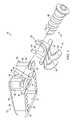
- FIG. 2illustrates an exploded view of an intervertebral disc prosthesis according to one embodiment of the present disclosure
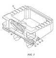
- FIG. 3illustrates a top perspective view of an interbody device and face plate of the intervertebral disc prosthesis of FIG. 2
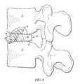
- FIG. 4illustrates a first position of the intervertebral disc prosthesis of FIG. 2 during an insertion procedure
- FIG. 5illustrates a second, engaged position of the intervertebral disc prosthesis of FIG. 2 ;
- FIG. 6Aillustrates an exemplary tool for inserting the intervertebral disc prosthesis of the present disclosure into an intervertebral disc space
- FIG. 6Billustrates a distal portion of the tool of FIG. 6A in section
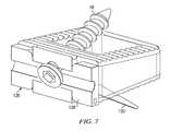
- FIG. 7illustrates an alternative intervertebral disc prosthesis according to another embodiment of the present disclosure.
- FIG. 1AA portion of a human spinal column 10 is schematically illustrated in FIG. 1A and includes a series of vertebrae 12 intersected by a series of intervertebral discs 14 .
- the vertebrae 12generally encapsulate a spinal cord 16 , which generally comprises nervous tissue and serves as the main pathway for information connecting the brain and peripheral nervous system.
- a spinal cord 16which generally comprises nervous tissue and serves as the main pathway for information connecting the brain and peripheral nervous system.
- FIG. 1Bit sometimes becomes necessary to remove a diseased, or otherwise failing, intervertebral disc. Such procedures leave an intervertebral disc space 18 defined between adjacent vertebrae of the spinal column.
- FIGS. 2-5An intervertebral disc prosthesis 20 according to some embodiments of the present disclosure is illustrated in FIGS. 2-5 .
- the prosthesis 20is preferably used in the cervical and/or lumbar regions of the spinal column, however, other regions of use are contemplated as falling within the scope of the present disclosure.
- the disc prosthesis 20includes an interbody device 22 and one or more fixation mechanisms 24 adapted for use with the interbody device.
- the disc prosthesis 20further includes a face plate 26 , which facilitates use of the fixation mechanisms 24 with the interbody device 22 .
- the interbody device 22is preferably formed of a PEEK material (e.g., with titanium X-ray markers), while the face plate 26 is preferably formed of titanium alloy, or Nitinol.
- the interbody device 22may be sized and shaped to correspond to the anatomical contour of an intervertebral disc space ( 18 in FIG. 1B ) created by the removal of an organic intervertebral disc ( 16 in FIG. 1B ).
- the interbody device 22is generally quadrilateral in shape and includes an anterior portion 30 , which is connected to a posterior portion 32 via two side portions 34 , 36 . Such portions cooperate to define a central opening 37 through the interbody device 22 , which allows for passage of the fixation mechanisms 24 (and packing of bone graft material) as will be further described.
- the side portions 34 , 36are slightly sloped in the anterior-posterior direction, thus resulting in a slightly smaller width at the posterior portion 32 of the interbody device 22 relative to the anterior portion 30 .
- the side portions 34 , 36may be relatively flat in the anterior-posterior direction, thus resulting in substantially the same width at the posterior portion 32 relative to the anterior portion 30 .
- the top and bottom surfaces of the side portions 34 , 36may include ribs 38 or some other undulating surface to provide increased gripping of the adjacent vertebral endplates.
- the anterior portion 30 of the interbody device 22includes a face portion 40 , which is preferably a recessed portion that extends in an oblique manner from a top side 42 of the interbody device 22 towards a bottom side 44 of the interbody device.
- the face portion 40matches the contour of the face plate 26 and includes an aperture 46 defined therethough to receive a locking mechanism.
- the fixation mechanismmay be a threaded screw 48 .
- other fixation mechanismsmay be used, such as pins and the like.
- the interbody device 22further includes a slot 50 formed in the bottom side 44 to receive a rod member 52 of the face plate 26 .
- An additional slot 53may be formed in the anterior portion 30 of the interbody device 22 to receive a retaining member 54 ( FIG. 3 ) to thereby protect against dislodgement of the face plate 26 from the interbody device when assembled.
- grooves 56may be formed in the anterior portion 30 to permit handling of the interbody device 22 during insertion procedures. For example, various tools may be used to grip the interbody device at the grooves 56 to facilitate insertion of the disc prosthesis 20 into the disc space ( 18 in FIG. 1B ) as will be further described.
- one of the fixation mechanisms 24 associated with the interbody device 22may be formed unitarily with the face plate 26 and include a pair of tusks 60 , which are adapted to engage an adjacent vertebral end plate (e.g, an endplate of the vertebrae 12 in FIG. 1A ).
- the tusks 60include sharpened endpoints 62 , often referred to in the industry as trocars, to impact the adjacent end plate.
- trocarsoften referred to in the industry as trocars
- the face plate 26is shaped to generally match the contour of the face portion 40 of the interbody device 22 . Accordingly, the face plate 26 preferably includes a U-shaped portion 64 , which is adapted to seat against the face portion 40 . A slot 66 defined by the U-shaped portion 64 of the face plate 26 matches the aperture 46 defined in the face portion 40 of the interbody device 22 such that these openings are aligned when the face plate is seated against the interbody device. In other embodiments, the face plate 26 may include an aperture formed therethrough which corresponds to the aperture 46 of the face portion 40 .
- the face plate 26further includes the laterally extending rod member 52 , which is shaped to fit into the slot 50 formed in the interbody device 22 .
- the rod member 52may be unitarily formed with the face plate 26 , or it may comprise a detachable member.
- the face plate 26in an initial position, is situated with the interbody device 22 in such a way that the tusks 66 are substantially positioned within the central opening 37 defined by the interbody device.
- the rod member 52provides a pivot point about which the face plate 26 may rotate to achieve a desired inserted position of the tusks 66 as will be described.
- an additional fixation mechanism 24may take the form of the threaded screw 48 , which cooperates with the interbody device 22 and face plate 26 to provide an additional point of engagement with the surrounding vertebral endplates (e.g., an opposing endplate relative to the endplate receiving the tusks 66 ).
- the screw 48includes a sharpened end point 72 , which is adapted to engage an intervertebral end plate to thereby secure the disc prosthesis 20 in the disc space as will be described.
- the threaded screw 48represents a preferred embodiment, other fixation mechanisms may be used such as pins, or other elongated devices.
- a surgeonmay implant the intervertebral disc prosthesis 20 into the disc space ( 18 in FIG. 1B ).
- the surgeonmay use a tool (an example of which is discussed with reference to FIG. 6 ) to grip the interbody device 22 at the grooves 56 and position the device adjacent the disc space 18 .
- the interbody device 22(with associated face plate 26 and tusks 60 ) may then be impacted into the disc space using conventional impaction techniques.
- the ribs 38 formed on the interbody device 22may facilitate initial securing of the interbody device within the disc space 18 .
- the screw 48may then be inserted through the aligned aperture 46 /slot 66 of the interbody device 22 and face plate 26 , respectively.
- insertion of the screw 48results in the screw extending in a oblique manner relative to the top and bottom sides 42 , 44 of the interbody device.
- the screwmay then be engaged with a screwdriver to facilitate insertion of the screw into the adjacent intervertebral endplate, thus providing an attachment point of the disc prosthesis 20 with the spinal segment.
- Continued insertion of the screw 48causes the head of the screw to engage the face plate 26 and urge the face plate against the face portion 40 .
- Such forcecauses the face plate 26 to rotate about the rod member 52 , which causes rotation of the tusks 66 into the adjacent vertebral endplate (in this embodiment, the endplate opposing the endplate receiving the screw 48 ).
- the tusks 66are accordingly further pushed into its associated endplate until the desired level of dual fixation is achieved, an example of which is shown in FIG. 5 .
- FIGS. 6A-BA tool 70 for inserting the disc prosthesis 20 into the intervertebral disc space 18 is illustrated in FIGS. 6A-B .
- the tool 70includes a distal gripping member 72 , which is adapted to grip the interbody device 22 for insertion into the intervertebral disc space 18 .
- the tool 70further includes a pin 74 connected to a sleeve 76 .
- pulling of the sleeve 76pushes pin 74 into a channel formed in the gripping member 72 , thus spreading gripping member apart.
- the gripping member 72closes and thus grips the interbody device 22 for insertion.
- the tool 70further includes an internal shaft 78 having a wedge-shaped member 80 disposed at a distal end thereof.
- the shaft 78may be actuated forward to urge the wedge-shaped member 80 against the interbody device 22 and into the intervertebral disc space.
- the member 80may take on shapes other than a wedge-shape, so long as it is capable of being urged against the interbody device 22 to thereby insert the interbody device into the disc space.
- the shaft 78may be actuated by rotating a knob 82 disposed adjacent to a handle 84 of the tool 70 .
- an alternative face plate 126may include a face portion 128 and a pair of staples 130 (or keels, one of which is shown in FIG. 7 ) extending at a generally oblique angle from the face portion.
- insertion of the screw 48will cause deformation of the face plate about a rod member (not shown) and thus insertion of the staples 130 into the adjacent vertebral endplate.
- the insertion procedure described hereininvolves single step fixation via insertion of a single screw or insertion instrument to fold up the face plate.
- single step fixationachieves dual-point fixation as screw insertion controls both cephalad fixation (via the screw 48 ) as well as caudal fixation (via the tusks 66 or staples 130 , which are activated by pivoting of the face plate 26 , 126 ).
- the positioning of the screw 48 relative to the interbody device 22facilitates repeatable trajectory, thus allowing surgeons to plan for required exposure.
- the dual fixation design of the intervertebral disc prosthesis 20offers alternative manners of insertion as the disc prosthesis may also be used in an inverted manner (i.e., the screw 48 may be utilized for caudal fixation and the tusks 66 for cephalad fixation).
Landscapes
- Health & Medical Sciences (AREA)
- Engineering & Computer Science (AREA)
- Biomedical Technology (AREA)
- Orthopedic Medicine & Surgery (AREA)
- Neurology (AREA)
- Transplantation (AREA)
- Heart & Thoracic Surgery (AREA)
- Oral & Maxillofacial Surgery (AREA)
- Cardiology (AREA)
- Vascular Medicine (AREA)
- Life Sciences & Earth Sciences (AREA)
- Animal Behavior & Ethology (AREA)
- General Health & Medical Sciences (AREA)
- Public Health (AREA)
- Veterinary Medicine (AREA)
- Physical Education & Sports Medicine (AREA)
- Prostheses (AREA)
Abstract
Description
Claims (17)
Priority Applications (9)
| Application Number | Priority Date | Filing Date | Title |
|---|---|---|---|
| US13/362,932US9198764B2 (en) | 2012-01-31 | 2012-01-31 | Intervertebral disc prosthesis and method |
| CA 2863081CA2863081A1 (en) | 2012-01-31 | 2013-01-31 | Intervertebral disc prosthesis and method |
| AU2013215075AAU2013215075B2 (en) | 2012-01-31 | 2013-01-31 | Intervertebral disc prosthesis and method |
| EP13743564.0AEP2809250B1 (en) | 2012-01-31 | 2013-01-31 | Intervertebral disc prosthesis |
| BR112014018017ABR112014018017A8 (en) | 2012-01-31 | 2013-01-31 | INTERVERTEBRAL DISC PROSTHESIS AND METHOD |
| PCT/US2013/024052WO2013116464A1 (en) | 2012-01-31 | 2013-01-31 | Intervertebral disc prosthesis and method |
| JP2014554985AJP6151719B2 (en) | 2012-01-31 | 2013-01-31 | Intervertebral disc prosthesis |
| US14/589,661US9283085B2 (en) | 2012-01-31 | 2015-01-05 | Intervertebral disc prosthesis and method |
| US14/954,742US9814594B2 (en) | 2012-01-31 | 2015-11-30 | Intervertebral disc prosthesis and method |
Applications Claiming Priority (1)
| Application Number | Priority Date | Filing Date | Title |
|---|---|---|---|
| US13/362,932US9198764B2 (en) | 2012-01-31 | 2012-01-31 | Intervertebral disc prosthesis and method |
Related Child Applications (1)
| Application Number | Title | Priority Date | Filing Date |
|---|---|---|---|
| US14/589,661DivisionUS9283085B2 (en) | 2012-01-31 | 2015-01-05 | Intervertebral disc prosthesis and method |
Publications (2)
| Publication Number | Publication Date |
|---|---|
| US20130197643A1 US20130197643A1 (en) | 2013-08-01 |
| US9198764B2true US9198764B2 (en) | 2015-12-01 |
Family
ID=48870925
Family Applications (3)
| Application Number | Title | Priority Date | Filing Date |
|---|---|---|---|
| US13/362,932Active2034-04-30US9198764B2 (en) | 2012-01-31 | 2012-01-31 | Intervertebral disc prosthesis and method |
| US14/589,661ActiveUS9283085B2 (en) | 2012-01-31 | 2015-01-05 | Intervertebral disc prosthesis and method |
| US14/954,742ActiveUS9814594B2 (en) | 2012-01-31 | 2015-11-30 | Intervertebral disc prosthesis and method |
Family Applications After (2)
| Application Number | Title | Priority Date | Filing Date |
|---|---|---|---|
| US14/589,661ActiveUS9283085B2 (en) | 2012-01-31 | 2015-01-05 | Intervertebral disc prosthesis and method |
| US14/954,742ActiveUS9814594B2 (en) | 2012-01-31 | 2015-11-30 | Intervertebral disc prosthesis and method |
Country Status (7)
| Country | Link |
|---|---|
| US (3) | US9198764B2 (en) |
| EP (1) | EP2809250B1 (en) |
| JP (1) | JP6151719B2 (en) |
| AU (1) | AU2013215075B2 (en) |
| BR (1) | BR112014018017A8 (en) |
| CA (1) | CA2863081A1 (en) |
| WO (1) | WO2013116464A1 (en) |
Cited By (7)
| Publication number | Priority date | Publication date | Assignee | Title |
|---|---|---|---|---|
| US20140094921A1 (en)* | 2012-10-02 | 2014-04-03 | Titan Spine, Llc | Implants with self-deploying anchors |
| US20160081813A1 (en)* | 2012-01-31 | 2016-03-24 | Blackstone Medical, Inc. | Intervertebral disc prosthesis and method |
| US9707100B2 (en) | 2015-06-25 | 2017-07-18 | Institute for Musculoskeletal Science and Education, Ltd. | Interbody fusion device and system for implantation |
| US20200046513A1 (en)* | 2017-07-18 | 2020-02-13 | Blue Sky Technologies, LLC | Joint Arthrodesis System |
| US10980575B2 (en) | 2011-12-23 | 2021-04-20 | Pioneer Surgical Technology, Inc. | Instrument for inserting a spinal device |
| US11872143B2 (en) | 2016-10-25 | 2024-01-16 | Camber Spine Technologies, LLC | Spinal fusion implant |
| US11877935B2 (en) | 2016-10-18 | 2024-01-23 | Camber Spine Technologies, LLC | Implant with deployable blades |
Families Citing this family (18)
| Publication number | Priority date | Publication date | Assignee | Title |
|---|---|---|---|---|
| US9220547B2 (en) | 2009-03-27 | 2015-12-29 | Spinal Elements, Inc. | Flanged interbody fusion device |
| US8740949B2 (en) | 2011-02-24 | 2014-06-03 | Spinal Elements, Inc. | Methods and apparatus for stabilizing bone |
| USD739935S1 (en) | 2011-10-26 | 2015-09-29 | Spinal Elements, Inc. | Interbody bone implant |
| US9421044B2 (en) | 2013-03-14 | 2016-08-23 | Spinal Elements, Inc. | Apparatus for bone stabilization and distraction and methods of use |
| US9351847B2 (en)* | 2013-08-22 | 2016-05-31 | Globus Medical, Inc. | Interbody fusion devices with self-affixing mechanisms |
| US9839450B2 (en) | 2013-09-27 | 2017-12-12 | Spinal Elements, Inc. | Device and method for reinforcement of a facet |
| US9456855B2 (en) | 2013-09-27 | 2016-10-04 | Spinal Elements, Inc. | Method of placing an implant between bone portions |
| US9918848B2 (en)* | 2013-10-07 | 2018-03-20 | Warsaw Orthopedic, Inc. | Spinal implant system and method |
| US9545320B2 (en)* | 2014-05-15 | 2017-01-17 | Globus Medical, Inc. | Standalone interbody implants |
| US11478275B2 (en) | 2014-09-17 | 2022-10-25 | Spinal Elements, Inc. | Flexible fastening band connector |
| AU2016212009C1 (en)* | 2015-01-27 | 2021-02-25 | Spinal Elements, Inc. | Facet joint implant |
| AU2019342137A1 (en) | 2018-09-20 | 2021-03-25 | Spinal Elements, Inc. | Spinal implant device |
| BR112021022695A2 (en) | 2019-05-22 | 2021-12-28 | Spinal Elements Inc | Bone tethering and bone tethering inserter |
| US11457959B2 (en) | 2019-05-22 | 2022-10-04 | Spinal Elements, Inc. | Bone tie and bone tie inserter |
| WO2021163313A1 (en) | 2020-02-14 | 2021-08-19 | Spinal Elements, Inc. | Bone tie methods |
| US11911284B2 (en) | 2020-11-19 | 2024-02-27 | Spinal Elements, Inc. | Curved expandable interbody devices and deployment tools |
| WO2022133456A1 (en) | 2020-12-17 | 2022-06-23 | Spinal Elements, Inc. | Spinal implant device |
| US12369952B2 (en) | 2021-12-10 | 2025-07-29 | Spinal Elements, Inc. | Bone tie and portal |
Citations (76)
| Publication number | Priority date | Publication date | Assignee | Title |
|---|---|---|---|---|
| US3426364A (en)* | 1966-08-25 | 1969-02-11 | Colorado State Univ Research F | Prosthetic appliance for replacing one or more natural vertebrae |
| US4401112A (en)* | 1980-09-15 | 1983-08-30 | Rezaian Seyed M | Spinal fixator |
| US4657550A (en)* | 1984-12-21 | 1987-04-14 | Daher Youssef H | Buttressing device usable in a vertebral prosthesis |
| US4759769A (en)* | 1987-02-12 | 1988-07-26 | Health & Research Services Inc. | Artificial spinal disc |
| US5059193A (en)* | 1989-11-20 | 1991-10-22 | Spine-Tech, Inc. | Expandable spinal implant and surgical method |
| US5258031A (en)* | 1992-01-06 | 1993-11-02 | Danek Medical | Intervertebral disk arthroplasty |
| US5556431A (en) | 1992-03-13 | 1996-09-17 | B+E,Uml U+Ee Ttner-Janz; Karin | Intervertebral disc endoprosthesis |
| FR2737656A1 (en) | 1995-08-09 | 1997-02-14 | Jbs Sa | IMPACTOR DEVICE FOR PLACING A PROSTHESIS FOR INTERVERTEBRAL DISCS |
| US5683394A (en)* | 1995-09-29 | 1997-11-04 | Advanced Spine Fixation Systems, Inc. | Fusion mass constrainer |
| US5713899A (en)* | 1995-04-27 | 1998-02-03 | Societe Jbs Sa | Cervical cage designed for the performance of intersomatic arthrodesis |
| US5776198A (en)* | 1994-12-09 | 1998-07-07 | Sdgi Holdings, Inc. | Adjustable vertebral body replacement |
| US5888228A (en)* | 1995-10-20 | 1999-03-30 | Synthes (U.S.A.) | Intervertebral implant with cage and rotating element |
| US5895428A (en)* | 1996-11-01 | 1999-04-20 | Berry; Don | Load bearing spinal joint implant |
| US6066175A (en)* | 1993-02-16 | 2000-05-23 | Henderson; Fraser C. | Fusion stabilization chamber |
| US6090143A (en)* | 1998-09-21 | 2000-07-18 | Meriwether; Michael W. | Box cage for intervertebral body fusion |
| US6093205A (en) | 1997-06-25 | 2000-07-25 | Bridport-Gundry Plc C/O Pearsalls Implants | Surgical implant |
| US6102950A (en)* | 1999-01-19 | 2000-08-15 | Vaccaro; Alex | Intervertebral body fusion device |
| US6156037A (en)* | 1998-10-28 | 2000-12-05 | Sdgi Holdings, Inc. | Anterior lateral spine cage-plate fixation device and technique |
| US6179873B1 (en)* | 1995-08-11 | 2001-01-30 | Bernhard Zientek | Intervertebral implant, process for widening and instruments for implanting an intervertebral implant |
| US6235059B1 (en)* | 1996-04-03 | 2001-05-22 | Scient'x (Societe A Responsabilite Limitee) | Intersomatic setting and fusion system |
| US20010020185A1 (en)* | 1997-04-25 | 2001-09-06 | Tegementa L.L.C. | Threaded fusion cage anchoring device and method |
| US20020004683A1 (en)* | 2000-07-10 | 2002-01-10 | Michelson Gary K. | Flanged interbody spinal fusion implants |
| US20020055738A1 (en)* | 2000-11-08 | 2002-05-09 | The Cleveland Clinic Foundation | Apparatus for implantation into bone |
| US20020055737A1 (en)* | 2000-11-08 | 2002-05-09 | The Cleveland Clinic Foundation | Apparatus for implantation into bone related applications |
| US20020107572A1 (en)* | 2001-02-06 | 2002-08-08 | Foley Kevin T. | Spinal implant with attached ligament |
| US6447546B1 (en)* | 2000-08-11 | 2002-09-10 | Dale G. Bramlet | Apparatus and method for fusing opposing spinal vertebrae |
| US20030045877A1 (en)* | 2001-08-29 | 2003-03-06 | Chung-Chun Yeh | Device for fixing spinal column under treatment |
| US20030125739A1 (en)* | 2001-12-12 | 2003-07-03 | Bagga Charanpreet S. | Bioactive spinal implants and method of manufacture thereof |
| US20030176925A1 (en)* | 2002-03-15 | 2003-09-18 | Francois Paponneau | Vertebral body spacer having variable wedged endplates |
| US20030187436A1 (en)* | 1999-07-01 | 2003-10-02 | Ciaran Bolger | Interbody spinal stabilization cage and spinal stabilization method |
| US20030229348A1 (en)* | 2000-05-25 | 2003-12-11 | Sevrain Lionel C. | Auxiliary vertebrae connecting device |
| US20040010254A1 (en)* | 1999-09-03 | 2004-01-15 | Cook Daniel J. | Lumbar spine fixation device |
| US20040034423A1 (en)* | 2002-04-25 | 2004-02-19 | Matthew Lyons | Artificial intervertebral disc |
| US20040049279A1 (en)* | 2000-05-25 | 2004-03-11 | Sevrain Lionel C. | Inter-vertebral disc prosthesis for rachis through anterior surgery thereof |
| US20040073313A1 (en)* | 2002-10-14 | 2004-04-15 | Link Spine Group, Inc. | System of intervertebral prostheses |
| US20040111161A1 (en)* | 2002-12-10 | 2004-06-10 | Trieu Hai H. | System and method for blocking and/or retaining a prosthetic spinal implant |
| US20040249461A1 (en)* | 1999-08-13 | 2004-12-09 | Ferree Bret A. | Coupled artificial disc replacements methods and apparatus |
| US20050060034A1 (en)* | 2003-09-15 | 2005-03-17 | Sdgi Holdings, Inc. | Revisable prosthetic device |
| US20050101960A1 (en)* | 2001-04-03 | 2005-05-12 | Vincent Fiere | Stabilised interbody fusion system for vertebrae |
| US20050165485A1 (en)* | 2004-01-27 | 2005-07-28 | Sdgi Holdings, Inc. | Hybrid intervertebral disc system |
| US20050177245A1 (en)* | 2004-02-05 | 2005-08-11 | Leatherbury Neil C. | Absorbable orthopedic implants |
| US20050216081A1 (en)* | 2004-03-29 | 2005-09-29 | Taylor Brett A | Arthroplasty spinal prosthesis and insertion device |
| US20050222683A1 (en)* | 2004-03-31 | 2005-10-06 | Sdgi Holdings | Shape memory alloy disc replacement device |
| US6972019B2 (en) | 2001-01-23 | 2005-12-06 | Michelson Gary K | Interbody spinal implant with trailing end adapted to receive bone screws |
| US20050283236A1 (en)* | 2002-11-12 | 2005-12-22 | Hassan Razian | Intervertebral cage with medial fixing plate |
| US20060074490A1 (en)* | 2004-10-01 | 2006-04-06 | Sweeney Patrick J | Vertebral prosthesis and spinal fixation system |
| US20060195100A1 (en)* | 2003-09-30 | 2006-08-31 | X-Spine Systems, Inc. | Spinal fusion system utilizing an implant plate having at least one integral lock |
| US20060224241A1 (en)* | 2005-03-31 | 2006-10-05 | Life Spine, Llc | Expandable spinal interbody and intravertebral body devices |
| US7135043B2 (en) | 2002-08-20 | 2006-11-14 | Showa Ika Kohgyo Co., Ltd. | Intervertebral cage |
| US20060282165A1 (en)* | 2004-03-19 | 2006-12-14 | Perumala Corporation | Intervertebral disc implant |
| US20070118225A1 (en)* | 2005-11-18 | 2007-05-24 | Zimmer Spine, Inc. | Artificial spinal discs and methods |
| US7235105B2 (en)* | 2003-09-18 | 2007-06-26 | Jackson Roger P | Threaded center line cage with winged end gap |
| US20070173936A1 (en) | 2006-01-23 | 2007-07-26 | Depuy Spine, Inc. | Intervertebral disc prosthesis |
| US20070191953A1 (en)* | 2006-01-27 | 2007-08-16 | Sdgi Holdings, Inc. | Intervertebral implants and methods of use |
| US20070213820A1 (en)* | 2003-04-23 | 2007-09-13 | Sepitec Foundation | Spondylodesis Device |
| US20070225806A1 (en)* | 2006-03-24 | 2007-09-27 | Sdgi Holdings, Inc. | Arthroplasty device |
| US20080051890A1 (en)* | 2006-08-11 | 2008-02-28 | Warsaw Orthopedic, Inc. | Intervertebral Implants with Attachable Flanges and Methods of Use |
| US20080051900A1 (en)* | 2006-07-28 | 2008-02-28 | Spinalmotion, Inc. | Spinal Prosthesis with Offset Anchors |
| US20080177390A1 (en)* | 2006-10-24 | 2008-07-24 | St. Francis Medical Technologies, Inc. | Disk Replacement Endoprosthesis |
| US20080294260A1 (en)* | 2007-05-22 | 2008-11-27 | Wayne Gray | Spinal implant system and method |
| US20080312698A1 (en)* | 2007-06-14 | 2008-12-18 | Bergeron Brian J | Device and system for stabilizing movement between bony tissue and method for implanting |
| EP2047825A1 (en) | 2007-10-11 | 2009-04-15 | International Spinal Innovations, LLC | Minimally invasivelateral intervertebral fixation system |
| US20090105831A1 (en) | 2007-10-19 | 2009-04-23 | Jones Robert J | Locking mechanisms and associated methods |
| US20090240333A1 (en)* | 2007-09-17 | 2009-09-24 | Trudeau Jeffrey L | Motion Preserving Artificial Intervertebral Disc Device |
| US7594932B2 (en)* | 2005-12-29 | 2009-09-29 | International Spinal Innovations, Llc | Apparatus for anterior intervertebral spinal fixation and fusion |
| US20100057206A1 (en)* | 2008-09-02 | 2010-03-04 | Duffield William E | Intervertebral fusion implant |
| US20100131067A1 (en)* | 2008-11-24 | 2010-05-27 | Warsaw Orthopedic, Inc. | Orthopedic implant with sensor communications antenna and associated diagnostics measuring, monitoring, and response system |
| US20100137989A1 (en) | 2008-12-02 | 2010-06-03 | Warsaw Orthopedic, Inc. | Intervertebral implant with fixation mechanism |
| WO2010071707A1 (en) | 2008-12-19 | 2010-06-24 | Amicus, Llc | Inter-body vertebral prosthetic device with self-deploying screws and insertion tool therefor |
| US20100204737A1 (en) | 2009-02-11 | 2010-08-12 | IMDS, Inc. | Intervertebral implant with integrated fixation |
| WO2010092893A1 (en) | 2009-02-10 | 2010-08-19 | 学校法人自治医科大学 | Surgical operation system for lumbar interbody fusion and device for keeping lumbar interbody space to be used in surgical operation for lumbar interbody fusion |
| US20100234958A1 (en)* | 2007-11-19 | 2010-09-16 | Linares Medical Devices, Llc | Combination spacer insert and support for providing inter-cervical vertebral support |
| US20110060415A1 (en)* | 2008-05-05 | 2011-03-10 | Maurice Bertholet | Intervertebral prosthetic device |
| US20110190892A1 (en)* | 2010-02-01 | 2011-08-04 | X-Spine Systems, Inc. | Spinal implant co-insertion system and method |
| US20110208311A1 (en) | 2007-11-28 | 2011-08-25 | Janowski Brian P | Device For Securing An Impalnt To Tissue |
| US20110230971A1 (en)* | 2009-04-15 | 2011-09-22 | Synthes Usa, Llc | Arcuate fixation member |
Family Cites Families (16)
| Publication number | Priority date | Publication date | Assignee | Title |
|---|---|---|---|---|
| US5609635A (en)* | 1988-06-28 | 1997-03-11 | Michelson; Gary K. | Lordotic interbody spinal fusion implants |
| US5800550A (en)* | 1996-03-13 | 1998-09-01 | Sertich; Mario M. | Interbody fusion cage |
| US6629998B1 (en)* | 2000-08-23 | 2003-10-07 | Chih-I Lin | Intervertebral retrieval device |
| US6358254B1 (en)* | 2000-09-11 | 2002-03-19 | D. Greg Anderson | Method and implant for expanding a spinal canal |
| AR038680A1 (en)* | 2002-02-19 | 2005-01-26 | Synthes Ag | INTERVERTEBRAL IMPLANT |
| US6908484B2 (en)* | 2003-03-06 | 2005-06-21 | Spinecore, Inc. | Cervical disc replacement |
| US9237958B2 (en)* | 2004-06-30 | 2016-01-19 | Synergy Disc Replacement Inc. | Joint prostheses |
| US20060095136A1 (en)* | 2004-11-03 | 2006-05-04 | Mcluen Design, Inc. | Bone fusion device |
| US7942903B2 (en)* | 2005-04-12 | 2011-05-17 | Moskowitz Ahmnon D | Bi-directional fixating transvertebral body screws and posterior cervical and lumbar interarticulating joint calibrated stapling devices for spinal fusion |
| GB0623801D0 (en)* | 2006-11-29 | 2007-01-10 | Surgicraft Ltd | Orthopaedic implants and prosthesis |
| US8142479B2 (en)* | 2007-05-01 | 2012-03-27 | Spinal Simplicity Llc | Interspinous process implants having deployable engagement arms |
| JP2008295547A (en)* | 2007-05-29 | 2008-12-11 | Olympus Terumo Biomaterials Corp | Intervertebral spacer |
| US8864832B2 (en)* | 2007-06-20 | 2014-10-21 | Hh Spinal Llc | Posterior total joint replacement |
| KR101692567B1 (en)* | 2009-04-15 | 2017-01-03 | 신세스 게엠바하 | Arcuate spinal fixation member |
| DE102010000231A1 (en)* | 2010-01-27 | 2011-07-28 | Aesculap AG, 78532 | Implant for the mutual support of spinous processes of adjacent vertebral bodies and surgical system |
| US9198764B2 (en)* | 2012-01-31 | 2015-12-01 | Blackstone Medical, Inc. | Intervertebral disc prosthesis and method |
- 2012
- 2012-01-31USUS13/362,932patent/US9198764B2/enactiveActive
- 2013
- 2013-01-31EPEP13743564.0Apatent/EP2809250B1/enactiveActive
- 2013-01-31CACA 2863081patent/CA2863081A1/ennot_activeAbandoned
- 2013-01-31AUAU2013215075Apatent/AU2013215075B2/ennot_activeCeased
- 2013-01-31JPJP2014554985Apatent/JP6151719B2/ennot_activeExpired - Fee Related
- 2013-01-31BRBR112014018017Apatent/BR112014018017A8/ennot_activeApplication Discontinuation
- 2013-01-31WOPCT/US2013/024052patent/WO2013116464A1/enactiveApplication Filing
- 2015
- 2015-01-05USUS14/589,661patent/US9283085B2/enactiveActive
- 2015-11-30USUS14/954,742patent/US9814594B2/enactiveActive
Patent Citations (83)
| Publication number | Priority date | Publication date | Assignee | Title |
|---|---|---|---|---|
| US3426364A (en)* | 1966-08-25 | 1969-02-11 | Colorado State Univ Research F | Prosthetic appliance for replacing one or more natural vertebrae |
| US4401112A (en)* | 1980-09-15 | 1983-08-30 | Rezaian Seyed M | Spinal fixator |
| US4657550A (en)* | 1984-12-21 | 1987-04-14 | Daher Youssef H | Buttressing device usable in a vertebral prosthesis |
| US4759769A (en)* | 1987-02-12 | 1988-07-26 | Health & Research Services Inc. | Artificial spinal disc |
| US5059193A (en)* | 1989-11-20 | 1991-10-22 | Spine-Tech, Inc. | Expandable spinal implant and surgical method |
| US5258031A (en)* | 1992-01-06 | 1993-11-02 | Danek Medical | Intervertebral disk arthroplasty |
| US5556431A (en) | 1992-03-13 | 1996-09-17 | B+E,Uml U+Ee Ttner-Janz; Karin | Intervertebral disc endoprosthesis |
| US6066175A (en)* | 1993-02-16 | 2000-05-23 | Henderson; Fraser C. | Fusion stabilization chamber |
| US5776198A (en)* | 1994-12-09 | 1998-07-07 | Sdgi Holdings, Inc. | Adjustable vertebral body replacement |
| US5713899A (en)* | 1995-04-27 | 1998-02-03 | Societe Jbs Sa | Cervical cage designed for the performance of intersomatic arthrodesis |
| FR2737656A1 (en) | 1995-08-09 | 1997-02-14 | Jbs Sa | IMPACTOR DEVICE FOR PLACING A PROSTHESIS FOR INTERVERTEBRAL DISCS |
| US6179873B1 (en)* | 1995-08-11 | 2001-01-30 | Bernhard Zientek | Intervertebral implant, process for widening and instruments for implanting an intervertebral implant |
| US5683394A (en)* | 1995-09-29 | 1997-11-04 | Advanced Spine Fixation Systems, Inc. | Fusion mass constrainer |
| US5888228A (en)* | 1995-10-20 | 1999-03-30 | Synthes (U.S.A.) | Intervertebral implant with cage and rotating element |
| US6235059B1 (en)* | 1996-04-03 | 2001-05-22 | Scient'x (Societe A Responsabilite Limitee) | Intersomatic setting and fusion system |
| US5895428A (en)* | 1996-11-01 | 1999-04-20 | Berry; Don | Load bearing spinal joint implant |
| US20010020185A1 (en)* | 1997-04-25 | 2001-09-06 | Tegementa L.L.C. | Threaded fusion cage anchoring device and method |
| US6093205A (en) | 1997-06-25 | 2000-07-25 | Bridport-Gundry Plc C/O Pearsalls Implants | Surgical implant |
| US6090143A (en)* | 1998-09-21 | 2000-07-18 | Meriwether; Michael W. | Box cage for intervertebral body fusion |
| US6156037A (en)* | 1998-10-28 | 2000-12-05 | Sdgi Holdings, Inc. | Anterior lateral spine cage-plate fixation device and technique |
| US6102950A (en)* | 1999-01-19 | 2000-08-15 | Vaccaro; Alex | Intervertebral body fusion device |
| US6770096B2 (en)* | 1999-07-01 | 2004-08-03 | Spinevision S.A. | Interbody spinal stabilization cage and spinal stabilization method |
| US20030187436A1 (en)* | 1999-07-01 | 2003-10-02 | Ciaran Bolger | Interbody spinal stabilization cage and spinal stabilization method |
| US20040249461A1 (en)* | 1999-08-13 | 2004-12-09 | Ferree Bret A. | Coupled artificial disc replacements methods and apparatus |
| US20040010254A1 (en)* | 1999-09-03 | 2004-01-15 | Cook Daniel J. | Lumbar spine fixation device |
| US20040049279A1 (en)* | 2000-05-25 | 2004-03-11 | Sevrain Lionel C. | Inter-vertebral disc prosthesis for rachis through anterior surgery thereof |
| US20030229348A1 (en)* | 2000-05-25 | 2003-12-11 | Sevrain Lionel C. | Auxiliary vertebrae connecting device |
| US20020004683A1 (en)* | 2000-07-10 | 2002-01-10 | Michelson Gary K. | Flanged interbody spinal fusion implants |
| US6447546B1 (en)* | 2000-08-11 | 2002-09-10 | Dale G. Bramlet | Apparatus and method for fusing opposing spinal vertebrae |
| US20020055737A1 (en)* | 2000-11-08 | 2002-05-09 | The Cleveland Clinic Foundation | Apparatus for implantation into bone related applications |
| US20020055738A1 (en)* | 2000-11-08 | 2002-05-09 | The Cleveland Clinic Foundation | Apparatus for implantation into bone |
| US6972019B2 (en) | 2001-01-23 | 2005-12-06 | Michelson Gary K | Interbody spinal implant with trailing end adapted to receive bone screws |
| US7442209B2 (en) | 2001-01-23 | 2008-10-28 | Warsaw Orthopedic, Inc. | Implant with trailing end adapted to receive bone screws |
| US7794502B2 (en) | 2001-01-23 | 2010-09-14 | Warsaw Orthopedic, Inc. | Implant with openings adapted to receive bone screws |
| US20020107572A1 (en)* | 2001-02-06 | 2002-08-08 | Foley Kevin T. | Spinal implant with attached ligament |
| US20050101960A1 (en)* | 2001-04-03 | 2005-05-12 | Vincent Fiere | Stabilised interbody fusion system for vertebrae |
| US20030045877A1 (en)* | 2001-08-29 | 2003-03-06 | Chung-Chun Yeh | Device for fixing spinal column under treatment |
| US7238203B2 (en)* | 2001-12-12 | 2007-07-03 | Vita Special Purpose Corporation | Bioactive spinal implants and method of manufacture thereof |
| US20030125739A1 (en)* | 2001-12-12 | 2003-07-03 | Bagga Charanpreet S. | Bioactive spinal implants and method of manufacture thereof |
| US20030176925A1 (en)* | 2002-03-15 | 2003-09-18 | Francois Paponneau | Vertebral body spacer having variable wedged endplates |
| US20040034423A1 (en)* | 2002-04-25 | 2004-02-19 | Matthew Lyons | Artificial intervertebral disc |
| US7135043B2 (en) | 2002-08-20 | 2006-11-14 | Showa Ika Kohgyo Co., Ltd. | Intervertebral cage |
| US20040073313A1 (en)* | 2002-10-14 | 2004-04-15 | Link Spine Group, Inc. | System of intervertebral prostheses |
| US20050283236A1 (en)* | 2002-11-12 | 2005-12-22 | Hassan Razian | Intervertebral cage with medial fixing plate |
| US20040111161A1 (en)* | 2002-12-10 | 2004-06-10 | Trieu Hai H. | System and method for blocking and/or retaining a prosthetic spinal implant |
| US20070213820A1 (en)* | 2003-04-23 | 2007-09-13 | Sepitec Foundation | Spondylodesis Device |
| US20050060034A1 (en)* | 2003-09-15 | 2005-03-17 | Sdgi Holdings, Inc. | Revisable prosthetic device |
| US7235105B2 (en)* | 2003-09-18 | 2007-06-26 | Jackson Roger P | Threaded center line cage with winged end gap |
| US20060195100A1 (en)* | 2003-09-30 | 2006-08-31 | X-Spine Systems, Inc. | Spinal fusion system utilizing an implant plate having at least one integral lock |
| US20050165485A1 (en)* | 2004-01-27 | 2005-07-28 | Sdgi Holdings, Inc. | Hybrid intervertebral disc system |
| US20050177245A1 (en)* | 2004-02-05 | 2005-08-11 | Leatherbury Neil C. | Absorbable orthopedic implants |
| US20060282165A1 (en)* | 2004-03-19 | 2006-12-14 | Perumala Corporation | Intervertebral disc implant |
| US20050216081A1 (en)* | 2004-03-29 | 2005-09-29 | Taylor Brett A | Arthroplasty spinal prosthesis and insertion device |
| US20050222683A1 (en)* | 2004-03-31 | 2005-10-06 | Sdgi Holdings | Shape memory alloy disc replacement device |
| US20060074490A1 (en)* | 2004-10-01 | 2006-04-06 | Sweeney Patrick J | Vertebral prosthesis and spinal fixation system |
| US20060224241A1 (en)* | 2005-03-31 | 2006-10-05 | Life Spine, Llc | Expandable spinal interbody and intravertebral body devices |
| US20070118225A1 (en)* | 2005-11-18 | 2007-05-24 | Zimmer Spine, Inc. | Artificial spinal discs and methods |
| US7594932B2 (en)* | 2005-12-29 | 2009-09-29 | International Spinal Innovations, Llc | Apparatus for anterior intervertebral spinal fixation and fusion |
| US20070173936A1 (en) | 2006-01-23 | 2007-07-26 | Depuy Spine, Inc. | Intervertebral disc prosthesis |
| US20070191953A1 (en)* | 2006-01-27 | 2007-08-16 | Sdgi Holdings, Inc. | Intervertebral implants and methods of use |
| US20070225806A1 (en)* | 2006-03-24 | 2007-09-27 | Sdgi Holdings, Inc. | Arthroplasty device |
| US20080051900A1 (en)* | 2006-07-28 | 2008-02-28 | Spinalmotion, Inc. | Spinal Prosthesis with Offset Anchors |
| US20080051890A1 (en)* | 2006-08-11 | 2008-02-28 | Warsaw Orthopedic, Inc. | Intervertebral Implants with Attachable Flanges and Methods of Use |
| US20080177390A1 (en)* | 2006-10-24 | 2008-07-24 | St. Francis Medical Technologies, Inc. | Disk Replacement Endoprosthesis |
| US20080294260A1 (en)* | 2007-05-22 | 2008-11-27 | Wayne Gray | Spinal implant system and method |
| US20080312698A1 (en)* | 2007-06-14 | 2008-12-18 | Bergeron Brian J | Device and system for stabilizing movement between bony tissue and method for implanting |
| US20090240333A1 (en)* | 2007-09-17 | 2009-09-24 | Trudeau Jeffrey L | Motion Preserving Artificial Intervertebral Disc Device |
| EP2047825A1 (en) | 2007-10-11 | 2009-04-15 | International Spinal Innovations, LLC | Minimally invasivelateral intervertebral fixation system |
| US8920505B2 (en) | 2007-10-11 | 2014-12-30 | International Spinal Innovations, Llc | Minimally invasive lateral intervertebral fixation system, device and method |
| US8167950B2 (en) | 2007-10-11 | 2012-05-01 | International Spinal Innovations, Llc | Minimally invasive lateral intervertbral fixation system, device and method |
| US20090105831A1 (en) | 2007-10-19 | 2009-04-23 | Jones Robert J | Locking mechanisms and associated methods |
| US20100234958A1 (en)* | 2007-11-19 | 2010-09-16 | Linares Medical Devices, Llc | Combination spacer insert and support for providing inter-cervical vertebral support |
| US20110208311A1 (en) | 2007-11-28 | 2011-08-25 | Janowski Brian P | Device For Securing An Impalnt To Tissue |
| US20110060415A1 (en)* | 2008-05-05 | 2011-03-10 | Maurice Bertholet | Intervertebral prosthetic device |
| US20100057206A1 (en)* | 2008-09-02 | 2010-03-04 | Duffield William E | Intervertebral fusion implant |
| US20100131067A1 (en)* | 2008-11-24 | 2010-05-27 | Warsaw Orthopedic, Inc. | Orthopedic implant with sensor communications antenna and associated diagnostics measuring, monitoring, and response system |
| US20100137989A1 (en) | 2008-12-02 | 2010-06-03 | Warsaw Orthopedic, Inc. | Intervertebral implant with fixation mechanism |
| US20100161057A1 (en) | 2008-12-19 | 2010-06-24 | Amicus, Llc | Interbody Vertebral Prosthetic Device With Self-Deploying Screws |
| WO2010071707A1 (en) | 2008-12-19 | 2010-06-24 | Amicus, Llc | Inter-body vertebral prosthetic device with self-deploying screws and insertion tool therefor |
| WO2010092893A1 (en) | 2009-02-10 | 2010-08-19 | 学校法人自治医科大学 | Surgical operation system for lumbar interbody fusion and device for keeping lumbar interbody space to be used in surgical operation for lumbar interbody fusion |
| US20100204737A1 (en) | 2009-02-11 | 2010-08-12 | IMDS, Inc. | Intervertebral implant with integrated fixation |
| US20110230971A1 (en)* | 2009-04-15 | 2011-09-22 | Synthes Usa, Llc | Arcuate fixation member |
| US20110190892A1 (en)* | 2010-02-01 | 2011-08-04 | X-Spine Systems, Inc. | Spinal implant co-insertion system and method |
Non-Patent Citations (2)
| Title |
|---|
| Extended European Search Report, EP Appl. No. 13743564.0, dated Sep. 2, 2015, 7 pages. |
| International Search Report and Written Opinion, PCT/US2013/024052, dated Apr. 15, 2013, 9 pages. |
Cited By (13)
| Publication number | Priority date | Publication date | Assignee | Title |
|---|---|---|---|---|
| US10980575B2 (en) | 2011-12-23 | 2021-04-20 | Pioneer Surgical Technology, Inc. | Instrument for inserting a spinal device |
| US11696786B2 (en) | 2011-12-23 | 2023-07-11 | Pioneer Surgical Technology, Inc. | Instrument for inserting a spinal device |
| US20160081813A1 (en)* | 2012-01-31 | 2016-03-24 | Blackstone Medical, Inc. | Intervertebral disc prosthesis and method |
| US9814594B2 (en)* | 2012-01-31 | 2017-11-14 | Blackstone Medical, Inc. | Intervertebral disc prosthesis and method |
| US9642721B2 (en)* | 2012-10-02 | 2017-05-09 | Titan Spine, Llc | Implants with self-deploying anchors |
| US20140094921A1 (en)* | 2012-10-02 | 2014-04-03 | Titan Spine, Llc | Implants with self-deploying anchors |
| US9707100B2 (en) | 2015-06-25 | 2017-07-18 | Institute for Musculoskeletal Science and Education, Ltd. | Interbody fusion device and system for implantation |
| US11877935B2 (en) | 2016-10-18 | 2024-01-23 | Camber Spine Technologies, LLC | Implant with deployable blades |
| US12329656B2 (en) | 2016-10-18 | 2025-06-17 | Camber Spine Technologies, LLC | Implant with deployable blades |
| US11872143B2 (en) | 2016-10-25 | 2024-01-16 | Camber Spine Technologies, LLC | Spinal fusion implant |
| US10980643B2 (en)* | 2017-07-18 | 2021-04-20 | Blue Sky Technologies, LLC | Joint implant |
| US10772738B2 (en)* | 2017-07-18 | 2020-09-15 | Blue Sky Technologies, LLC | Joint arthrodesis system |
| US20200046513A1 (en)* | 2017-07-18 | 2020-02-13 | Blue Sky Technologies, LLC | Joint Arthrodesis System |
Also Published As
| Publication number | Publication date |
|---|---|
| US20130197643A1 (en) | 2013-08-01 |
| WO2013116464A1 (en) | 2013-08-08 |
| BR112014018017A2 (en) | 2017-06-20 |
| JP2015504772A (en) | 2015-02-16 |
| AU2013215075B2 (en) | 2016-10-13 |
| CA2863081A1 (en) | 2013-08-08 |
| US9283085B2 (en) | 2016-03-15 |
| AU2013215075A1 (en) | 2014-07-24 |
| EP2809250B1 (en) | 2019-09-11 |
| EP2809250A1 (en) | 2014-12-10 |
| US20160081813A1 (en) | 2016-03-24 |
| BR112014018017A8 (en) | 2017-07-11 |
| US20150119991A1 (en) | 2015-04-30 |
| EP2809250A4 (en) | 2015-10-07 |
| US9814594B2 (en) | 2017-11-14 |
| JP6151719B2 (en) | 2017-06-21 |
Similar Documents
| Publication | Publication Date | Title |
|---|---|---|
| US9814594B2 (en) | Intervertebral disc prosthesis and method | |
| US11850159B2 (en) | Surgical implant with guiding rail | |
| US20230112704A1 (en) | Spinal fusion devices, systems and methods | |
| ES2563172T3 (en) | Flexible intersomatic implant | |
| US7959675B2 (en) | Spine implant insertion device and method | |
| JP4699997B2 (en) | Spinal implant | |
| US10568747B2 (en) | Instrument for inserting a spinal implant and a spinal implant | |
| US8262666B2 (en) | Implantable distractor | |
| US8298235B2 (en) | Instrument and method for the insertion and alignment of an intervertebral implant | |
| US8603175B2 (en) | Method of inserting surgical implant with guiding rail | |
| US8425529B2 (en) | Instrument for inserting surgical implant with guiding rail | |
| JP2003038534A (en) | Module type fixed gauge, spinal implant system and method of implanting spinal disc prosthesis | |
| KR20080113029A (en) | Cervical intervertebral intersomatic cage and its insertion mechanism | |
| US20080262501A1 (en) | Multi-function corpectomy instrument | |
| US20150289993A1 (en) | End plate slider/distractor for posterior intervertebral device and method | |
| CA3119074A1 (en) | Intervertebral spinal implant and surgical methods |
Legal Events
| Date | Code | Title | Description |
|---|---|---|---|
| AS | Assignment | Owner name:BLACKSTONE MEDICAL, INC., NEW JERSEY Free format text:ASSIGNMENT OF ASSIGNORS INTEREST;ASSIGNORS:GREENBERG, DANIEL;KLEIN, JAMES;SIGNING DATES FROM 20120120 TO 20120123;REEL/FRAME:027631/0369 | |
| AS | Assignment | Owner name:JPMORGAN CHASE BANK, N.A., AS ADMINISTRATIVE AGENT Free format text:SECURITY INTEREST;ASSIGNOR:BLACKSTONE MEDICAL, INC.;REEL/FRAME:036682/0192 Effective date:20150831 | |
| STCF | Information on status: patent grant | Free format text:PATENTED CASE | |
| CC | Certificate of correction | ||
| MAFP | Maintenance fee payment | Free format text:PAYMENT OF MAINTENANCE FEE, 4TH YEAR, LARGE ENTITY (ORIGINAL EVENT CODE: M1551); ENTITY STATUS OF PATENT OWNER: LARGE ENTITY Year of fee payment:4 | |
| AS | Assignment | Owner name:JPMORGAN CHASE BANK, N.A., ILLINOIS Free format text:SECURITY INTEREST;ASSIGNOR:ORTHOFIX SPINAL IMPLANTS INC.;REEL/FRAME:050839/0856 Effective date:20191025 | |
| AS | Assignment | Owner name:ORTHOFIX SPINAL IMPLANTS INC., TEXAS Free format text:CHANGE OF NAME;ASSIGNOR:BLACKSTONE MEDICAL, INC.;REEL/FRAME:054458/0045 Effective date:20181221 | |
| AS | Assignment | Owner name:ORTHOFIX HOLDINGS, INC., TEXAS Free format text:MERGER;ASSIGNOR:ORTHOFIX SPINAL IMPLANTS INC.;REEL/FRAME:055002/0751 Effective date:20201230 Owner name:ORTHOFIX INC., TEXAS Free format text:MERGER;ASSIGNOR:ORTHOFIX HOLDINGS, INC.;REEL/FRAME:055002/0841 Effective date:20201230 | |
| AS | Assignment | Owner name:JPMORGAN CHASE BANK, N.A., AS ADMINISTRATIVE ASSISTANT, ILLINOIS Free format text:SECURITY INTEREST;ASSIGNOR:ORTHOFIX US LLC;REEL/FRAME:056000/0153 Effective date:20210420 | |
| AS | Assignment | Owner name:ORTHOFIX US LLC, TEXAS Free format text:ENTITY CONVERSION;ASSIGNOR:ORTHOFIX INC.;REEL/FRAME:057247/0265 Effective date:20201231 | |
| MAFP | Maintenance fee payment | Free format text:PAYMENT OF MAINTENANCE FEE, 8TH YEAR, LARGE ENTITY (ORIGINAL EVENT CODE: M1552); ENTITY STATUS OF PATENT OWNER: LARGE ENTITY Year of fee payment:8 | |
| AS | Assignment | Owner name:ORTHOFIX SPINAL IMPLANTS INC., TEXAS Free format text:RELEASE BY SECURED PARTY;ASSIGNOR:JPMORGAN CHASE BANK, N.A.;REEL/FRAME:065609/0247 Effective date:20231106 Owner name:ORTHOFIX US LLC, TEXAS Free format text:RELEASE BY SECURED PARTY;ASSIGNOR:JPMORGAN CHASE BANK, N.A.;REEL/FRAME:065609/0223 Effective date:20231106 | |
| AS | Assignment | Owner name:BLUE TORCH FINANCE LLC, AS COLLATERAL AGENT, NEW YORK Free format text:SECURITY INTEREST;ASSIGNOR:ORTHOFIX US LLC;REEL/FRAME:066256/0423 Effective date:20231106 | |
| AS | Assignment | Owner name:OXFORD FINANCE LLC, AS AGENT, VIRGINIA Free format text:SECURITY INTEREST;ASSIGNORS:ORTHOFIX MEDICAL INC.;ORTHOFIX US LLC;SPINAL KINETICS LLC;AND OTHERS;REEL/FRAME:069332/0761 Effective date:20241107 | |
| AS | Assignment | Owner name:THEKEN SPINE, LLC, CALIFORNIA Free format text:RELEASE BY SECURED PARTY;ASSIGNOR:BLUE TORCH FINANCE LLC;REEL/FRAME:069358/0110 Effective date:20241111 Owner name:SPINAL KINETICS LLC, CALIFORNIA Free format text:RELEASE BY SECURED PARTY;ASSIGNOR:BLUE TORCH FINANCE LLC;REEL/FRAME:069358/0110 Effective date:20241111 Owner name:SEASPINE ORTHOPEDICS CORPORATION, CALIFORNIA Free format text:RELEASE BY SECURED PARTY;ASSIGNOR:BLUE TORCH FINANCE LLC;REEL/FRAME:069358/0110 Effective date:20241111 Owner name:SEASPINE, INC., CALIFORNIA Free format text:RELEASE BY SECURED PARTY;ASSIGNOR:BLUE TORCH FINANCE LLC;REEL/FRAME:069358/0110 Effective date:20241111 Owner name:ORTHOFIX US, LLC, TEXAS Free format text:RELEASE BY SECURED PARTY;ASSIGNOR:BLUE TORCH FINANCE LLC;REEL/FRAME:069358/0110 Effective date:20241111 Owner name:ISOTIS ORTHOBIOLOGICS, INC., CALIFORNIA Free format text:RELEASE BY SECURED PARTY;ASSIGNOR:BLUE TORCH FINANCE LLC;REEL/FRAME:069358/0110 Effective date:20241111 |