US9198692B1 - Spinal fixation anchor - Google Patents
Spinal fixation anchorDownload PDFInfo
- Publication number
- US9198692B1 US9198692B1US13/371,370US201213371370AUS9198692B1US 9198692 B1US9198692 B1US 9198692B1US 201213371370 AUS201213371370 AUS 201213371370AUS 9198692 B1US9198692 B1US 9198692B1
- Authority
- US
- United States
- Prior art keywords
- extension
- guide
- rod
- arm
- breakable
- Prior art date
- Legal status (The legal status is an assumption and is not a legal conclusion. Google has not performed a legal analysis and makes no representation as to the accuracy of the status listed.)
- Active, expires
Links
- 238000003780insertionMethods0.000claimsabstractdescription16
- 230000037431insertionEffects0.000claimsabstractdescription16
- 230000033001locomotionEffects0.000claimsdescription13
- 238000000034methodMethods0.000claimsdescription13
- 239000000463materialSubstances0.000claimsdescription12
- 210000000988bone and boneAnatomy0.000claimsdescription8
- 230000000295complement effectEffects0.000claimsdescription4
- 230000008878couplingEffects0.000claimsdescription2
- 238000010168coupling processMethods0.000claimsdescription2
- 238000005859coupling reactionMethods0.000claimsdescription2
- 238000004873anchoringMethods0.000claims2
- 239000007943implantSubstances0.000abstractdescription4
- 230000008901benefitEffects0.000description4
- 230000004927fusionEffects0.000description3
- 238000001356surgical procedureMethods0.000description3
- 230000008468bone growthEffects0.000description2
- 238000011161developmentMethods0.000description2
- 210000004705lumbosacral regionAnatomy0.000description2
- 238000005452bendingMethods0.000description1
- 238000012937correctionMethods0.000description1
- 230000000994depressogenic effectEffects0.000description1
- 238000002513implantationMethods0.000description1
- 238000009434installationMethods0.000description1
- 210000003205muscleAnatomy0.000description1
- 239000007787solidSubstances0.000description1
- 238000013519translationMethods0.000description1
Images


Classifications
- A—HUMAN NECESSITIES
- A61—MEDICAL OR VETERINARY SCIENCE; HYGIENE
- A61B—DIAGNOSIS; SURGERY; IDENTIFICATION
- A61B17/00—Surgical instruments, devices or methods
- A61B17/56—Surgical instruments or methods for treatment of bones or joints; Devices specially adapted therefor
- A61B17/58—Surgical instruments or methods for treatment of bones or joints; Devices specially adapted therefor for osteosynthesis, e.g. bone plates, screws or setting implements
- A61B17/68—Internal fixation devices, including fasteners and spinal fixators, even if a part thereof projects from the skin
- A61B17/70—Spinal positioners or stabilisers, e.g. stabilisers comprising fluid filler in an implant
- A61B17/7001—Screws or hooks combined with longitudinal elements which do not contact vertebrae
- A61B17/7032—Screws or hooks with U-shaped head or back through which longitudinal rods pass
- A—HUMAN NECESSITIES
- A61—MEDICAL OR VETERINARY SCIENCE; HYGIENE
- A61B—DIAGNOSIS; SURGERY; IDENTIFICATION
- A61B17/00—Surgical instruments, devices or methods
- A61B17/56—Surgical instruments or methods for treatment of bones or joints; Devices specially adapted therefor
- A61B17/58—Surgical instruments or methods for treatment of bones or joints; Devices specially adapted therefor for osteosynthesis, e.g. bone plates, screws or setting implements
- A61B17/68—Internal fixation devices, including fasteners and spinal fixators, even if a part thereof projects from the skin
- A61B17/70—Spinal positioners or stabilisers, e.g. stabilisers comprising fluid filler in an implant
- A61B17/7074—Tools specially adapted for spinal fixation operations other than for bone removal or filler handling
- A61B17/7083—Tools for guidance or insertion of tethers, rod-to-anchor connectors, rod-to-rod connectors, or longitudinal elements
- A61B17/7086—Rod reducers, i.e. devices providing a mechanical advantage to allow a user to force a rod into or onto an anchor head other than by means of a rod-to-bone anchor locking element; rod removers
- A—HUMAN NECESSITIES
- A61—MEDICAL OR VETERINARY SCIENCE; HYGIENE
- A61B—DIAGNOSIS; SURGERY; IDENTIFICATION
- A61B17/00—Surgical instruments, devices or methods
- A61B17/56—Surgical instruments or methods for treatment of bones or joints; Devices specially adapted therefor
- A61B17/58—Surgical instruments or methods for treatment of bones or joints; Devices specially adapted therefor for osteosynthesis, e.g. bone plates, screws or setting implements
- A61B17/68—Internal fixation devices, including fasteners and spinal fixators, even if a part thereof projects from the skin
- A61B17/70—Spinal positioners or stabilisers, e.g. stabilisers comprising fluid filler in an implant
- A61B17/7074—Tools specially adapted for spinal fixation operations other than for bone removal or filler handling
- A61B17/7091—Tools specially adapted for spinal fixation operations other than for bone removal or filler handling for applying, tightening or removing longitudinal element-to-bone anchor locking elements, e.g. caps, set screws, nuts or wedges
- A—HUMAN NECESSITIES
- A61—MEDICAL OR VETERINARY SCIENCE; HYGIENE
- A61B—DIAGNOSIS; SURGERY; IDENTIFICATION
- A61B17/00—Surgical instruments, devices or methods
- A61B17/56—Surgical instruments or methods for treatment of bones or joints; Devices specially adapted therefor
- A61B17/58—Surgical instruments or methods for treatment of bones or joints; Devices specially adapted therefor for osteosynthesis, e.g. bone plates, screws or setting implements
- A61B17/68—Internal fixation devices, including fasteners and spinal fixators, even if a part thereof projects from the skin
- A61B17/70—Spinal positioners or stabilisers, e.g. stabilisers comprising fluid filler in an implant
- A61B17/7074—Tools specially adapted for spinal fixation operations other than for bone removal or filler handling
- A61B17/7083—Tools for guidance or insertion of tethers, rod-to-anchor connectors, rod-to-rod connectors, or longitudinal elements
- A61B17/7085—Tools for guidance or insertion of tethers, rod-to-anchor connectors, rod-to-rod connectors, or longitudinal elements for insertion of a longitudinal element down one or more hollow screw or hook extensions, i.e. at least a part of the element within an extension has a component of movement parallel to the extension's axis
- A—HUMAN NECESSITIES
- A61—MEDICAL OR VETERINARY SCIENCE; HYGIENE
- A61B—DIAGNOSIS; SURGERY; IDENTIFICATION
- A61B90/00—Instruments, implements or accessories specially adapted for surgery or diagnosis and not covered by any of the groups A61B1/00 - A61B50/00, e.g. for luxation treatment or for protecting wound edges
- A61B90/03—Automatic limiting or abutting means, e.g. for safety
- A61B2090/037—Automatic limiting or abutting means, e.g. for safety with a frangible part, e.g. by reduced diameter
Definitions
- This applicationdescribes surgical instruments and implants for building a posterior fixation construct across one or more segments of the spinal column.
- Fixation constructsare utilized to provide stability to the spine. Most often the fixation construct is used as an adjunct to fusion surgery during which adjacent vertebrae are prepared to facilitate bone growth between them, thereby eliminating motion between the vertebrae. Because motion between the vertebrae tends to inhibit bone growth, the fixation constructs are employed to prevent motion so that bone can grow and achieve a solid fusion. When the position of one or more vertebrae must be adjusted to restore a more natural alignment of the spinal column, the fixation construct also serves to maintain the new alignment until fusion is achieved. Fixation constructs of various forms are well known in the art.
- the fixation constructis a plate anchored to the anterior column with multiple bone anchors or a posterior fixation construct including multiple anchors and a connecting rod anchored to the posterior elements of the spine.
- the anchorstypically pedicle screws
- the anchorsare then connected by a fixation rod that is locked to each anchor, thus eliminating motion between the adjacent vertebrae of the motion segment.
- the posterior fixation constructmay be applied unilaterally or bilaterally. Additionally the posterior fixation construct may be applied across multiple levels or motion segments.
- the fixation anchors utilized in posterior fixation constructsgenerally include an anchor portion and a rod housing.
- the rod housingincludes a pair of upstanding arms separated by a rod channel in which the fixation rod is captured and locked.
- the surgeonWhen constructing the posterior fixation construct the surgeon must align and seat the rod in the rod channel. This can be a challenge, particularly when one or more of the vertebrae to be connected is out of alignment leaving the associated anchor offset vertically and/or horizontally from the remaining anchor(s) of the construct.
- Constructing the posterior fixation construct under minimally invasive access conditionse.g. minimizing overall incision length and muscle stripping as compared to traditional open procedures
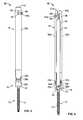
- FIG. 1is a perspective view of the spinal fixation anchor according to an example embodiment
- FIG. 2is a perspective view of an implantable portion of the fixation anchor of FIG. 1 after removal of an extension guide;
- FIGS. 3-4are side and front views, respectively, of the spinal fixation anchor of FIG. 1 ;
- FIG. 5is an enlarged perspective view of the junction between the implantable portion and extension guide of the fixation anchor of FIG. 1 ;
- FIG. 6is an enlarged front view of the junction region between the implantable portion and extension guide of the fixation anchor of FIG. 1 ;
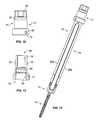
- FIG. 7is a side view of a breaking tool, according to an example embodiment
- FIG. 8is an exploded perspective view of the breaking tool of FIG. 7 ;
- FIG. 9is a front view of the fixation anchor of FIG. 1 , after proximal joints are broken to allow the arms to separate;
- FIG. 10is a perspective view of a guide cap for use with the fixation anchor of FIG. 1 , according to one example embodiment
- FIG. 11is another perspective view of the guide cap of FIG. 10 ;
- FIG. 12is a side view of the guide cap of FIG. 10 ;
- FIG. 13is a cross section view of the guide cap as shown in FIG. 12 ;
- FIG. 14is a perspective view of the guide cap of FIG. 10 coupled to the fixation anchor of FIG. 1 ;
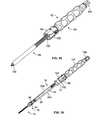
- FIG. 15is a perspective view of an independent reduction tool that may be used with the guide cap and fixation anchor of FIG. 15 ;
- FIG. 16is a front view of the independent reduction tool coupled to the guide cap and fixation anchor of FIG. 16 ;
- FIG. 17is a perspective view of a lumbar spine illustrating the use of spinal fixation anchors of FIG. 1 with the guide cap of FIG. 10 and independent reduction instrument of FIG. 15 to implant a two level fixation construct, according to one example;
- FIG. 18is a perspective view of the lumbar spine of FIG. 17 after the locking caps have been deployed and extension guides have been removed to leave the final fixation construct.
- the present applicationdescribes a spinal fixation anchor 10 that may be utilized to form a fixation construct across one or more spinal levels of a patient.
- the spinal fixation anchormay be especially useful in forming fixation constructs across multiple spinal levels and/or spines with alignment deformities requiring correction.
- the spinal fixation anchorincludes integral reduction features that may be utilized to seat a fixation rod in the anchor while realigning the position of the associated vertebra relative to other vertebra associated with the fixation construct. Additionally, separate reduction tools that cooperate with the spinal fixation anchor may be utilized to help seat the rod and realign the associated spinal segment.
- the spinal fixation anchormay also aid in installation of the fixation construct under minimally invasive conditions.
- the spinal fixation anchorincludes an extension guide that extends distally out of the patient when the anchor is engaged to the spine.
- An elongated rod channel through the extension guidehelps direct the rod into the proper position without requiring the extended incisions needed to fully expose the spinal segments to be fixated.
- the fixation anchor 10includes a bone anchor 12 (e.g. shank with thread feature 14 ) suitable for stable fixation to vertebral bone and a housing 16 for capturing and locking a fixation rod 50 .
- a bone anchor 12e.g. shank with thread feature 14
- a housing 16for capturing and locking a fixation rod 50 .
- Attached to the housing 16is a break-off extension guide 18 .
- the extension guide 18helps align the rod 50 with the housing 16 and also helps reduce the rod into the housing when necessary. After the rod 50 is locked within housing 16 the extension guide 18 can be removed from the housing so the incision can be closed over the fixation construct ( FIG. 2 depicts the fixation anchor with the extension guide 18 completely removed).
- the housing 16has a base 20 that mates with the bone anchor 12 and a pair of upstanding arms 22 a and 22 b separated by a rod channel 24 .
- the arms 22 a and 22 bare equipped with a locking cap guide and advancement feature 26 , such as by way of example, a helically wound flange feature disposed on the interior face of each arm 22 a and 22 b .
- the locking cap guide and advancement featuremates with a complementary guide and advancement feature on a locking cap 51 .
- the locking cap 51engages the upstanding arms via the complementary guide and advancement features to press and lock the fixation rod 50 into the housing 16 .
- the housing 16 and anchor 12may be mated with a polyaxial engagement such that the housing 16 can pivot relative to the anchor 12 in any direction.
- the engagementmay also be such that the pivoting movement may be inhibited in one or more directions.
- the housing 16 and anchor 12may be mated with a uniplanar engagement such that the housing pivots relative to the anchor 12 in a single plane.
- the housing 16 and anchor 12may also be fixed such that no movement is possible between the housing 16 and anchor 12 .
- Break-off extension guide 18extends from the top of housing 16 and includes a pair of extension arms 30 a and 30 b .
- Extension arm 30 aattaches to housing arm 22 a via an integral but breakable distal joint 32 a .
- Extension arm 30 battaches to the housing arm 22 b via an integral but breakable distal joint 32 b .
- the breakable distal joints 32 a and 32 bare formed by surface grooves which reduce the material thickness along the entire junction between the extension arms 30 a , 30 b and housing arms 22 a , 22 b , respectively, such that directing an appropriate force to the extension arm will snap the associated breakable joint.
- the extension arms 30 a and 30 bare dimensioned with a length such that the extension guide 18 extends from the housing 16 to a location outside of the patient when the fixation anchor 10 is in a fully implanted position and securely anchored to the vertebra. At a proximal end 34 of the extension guide 18 the extension arms 30 a and 30 b come together to form a pair of integral but breakable proximal joints 36 . Opposed vertical surface grooves above the guide slots 38 reduce material thickness along each junction between the extension arms 30 a and 30 b to form the breakable proximal joints 36 .
- Opposed guide slots 38 formed between arms 30 a and 30 balign with the rod channel 24 of the anchor housing 16 to define an enclosed guide channel 40 which is dimensioned to allow passage of a fixation rod 50 .
- Utilizing the guide channel 40 to align the rod 50 with the housing rod channel 24reduces the need for fiddlesome manipulation of the housing and/or rod down near the target site, as well as the associated need to fully visualize the housing 16 during rod insertion.
- the overall size of the incision required to implant a fixation construct using fixation anchors 10is significantly reduced compared to open procedures.
- the proximal joints 36may be broken, thereby severing the proximal connection of the extension arms 30 a and 30 b and allowing the arms 30 a and 30 b to flex apart ( FIG. 9 ).
- a guide cap 71(described below) may be used to reassociate the extension arms 30 a and 30 b if desired. Recess 40 a on the proximal end of extension arm 30 a and recess 40 b on the proximal end of extension arm 30 b facilitate the releasable coupling of the guide cap 71 to the proximal end 34 of the extension guide 18 .
- the fixation anchor 10includes an integral reduction feature which provides for effective, single step reduction and locking when the spinal alignment necessitates the rod be reduced into the housing 16 .
- the distal ends of extension arms 30 a and 30 bare appointed with a locking cap guide and advancement feature 42 situated adjacent to the breakable distal joints 32 a and 32 b .
- the guide and advancement feature 42matches the guide and advancement feature 26 on the interior face of arms 22 a and 22 b .
- the guide and advancement feature 42is timed with the guide and advancement feature 26 such that the locking cap 51 advances seamlessly from the extension guide 18 to the housing 16 .
- This configurationprovides a mechanical advantage when advancing the locking cap 51 along the guide and advancement features 42 and 26 , allowing the locking cap 51 to drive the rod into the housing 16 until it is fully seated and locked in position.
- the breakable distal joints 32 a , 32 b and the breakable proximal joints 36must be broken in order to remove the break-off extension guide 18 .
- the distal joints 32 a and 32 bare preferably broken only after the rod 50 is seated in the housing 16 and the locking cap 51 is fully engaged.
- an attachment groove 39 ais formed in the housing arm 22 a and an attachment groove 39 b is formed in housing arm 22 b .
- a slip on guide structuremay be advanced and releasably coupled to the housing via the attachment grooves 39 a , 39 b .
- the proximal breaking joints 36are preferably broken first before attempting break the distal joints 32 a , 32 b . This may be done just prior to breaking the distal joints to remove the extension guide after the rod 50 is seated and the locking cap 51 fully engaged in the housing 16 . Alternatively, the surgeon may want to sever the connection between the extension arms 30 a , 30 b at an earlier point during the procedure. By way of example, the proximal joints 36 may be severed prior to rod insertion in order to facilitate easier rod insertion.
- the breaking tool 44is designed to apply an outwardly directed force to the proximal joints 36 from inside the extension guide 18 .
- the breaking tool 44is a cam driver and includes a handle 46 , rotating drive shaft 48 , a cam 64 coupled to a distal end of the drive shaft 48 , a hub 50 , and a counter torque handle 52 .
- the hub 50has central cap 54 from which a cylinder 56 extends distally and a faceted block 58 extends proximally.
- the cylinder 56has an exterior diameter that is slightly smaller than an interior diameter of the extension guide 18 such that the cylinder 56 can be passed into the extension guide 18 .
- the central cap 54has a diameter that is larger than the extension guide 18 such that the cap 54 controls the depth of insertion into the extension guide 18 , ensuring force is applied in the right locations (i.e. on or near the proximal joints 36 ).
- the faceted block 58mates with a complementary receptacle 60 attached to the counter torque handle 52 to prevent rotation of the hub 50 when the drive shaft 48 is operated.
- a tunnel 66 dimensioned to receive a portion of the drive shaft 48 therethroughextends through the hub 50 along a line offset from a center axis of the cylinder 56 .
- the cam 64has a diameter that matches approximately the diameter of the cylinder 56 and a tunnel 68 for receiving the drive shaft 48 that is offset from the center axis of the cam.
- the cam 64is fixed to the drive shaft 48 via pin 70 such that rotation of the drive shaft 48 causes the cam 64 to rotate relative to the cylinder 56 . When the cam 64 and cylinder 56 are aligned they can slide together into the extension guide 18 .
- the cam 64As the cam 64 is rotated relative to the cylinder 56 the combined diameter of the two components expands, directing an outward force onto the extension arms 30 a , 30 b which causes the breakable proximal joints 36 to break, allowing the extension arms 30 a , 30 b to separate, as shown in FIG. 9 .
- the proximal joints 36 severedthe distal breakable joints 32 a and 32 b can be broken simply by bending the associated extension arm until the joint snaps. This can be done using a common grasping tool, such as forceps for example, or grasping the extensions arms directly with the hand.
- a guide cap 71is provided which may be used to hold the arm extensions 30 a and 30 b together and restore the rigidity of the unbroken guide extension 18 .
- the guide cap 71has a body 72 with a first internal cavity 73 opening out to a distal end 74 and a second internal cavity 76 opening out to a proximal end 78 .
- the first internal cavity 73has an internal diameter that is just larger than the external diameter of the extension guide 18 such that the proximal end of the extension guide may be received in the first internal cavity 73 .
- the second internal cavity 76has a diameter smaller than the first internal cavity 73 , to provide a shelf for spring 88 , approximating the internal diameter of the extension guide 18 and large enough to pass a locking cap 51 therethrough.
- a pair of opposed projections 80extend into the first internal cavity 73 and engage with the recesses 40 a and 40 b on the extension arms 30 a and 30 b to releasably couple the guide cap 71 to the extension guide 18 .
- the recesses 40 a and 40 beach include an open vertical slot 82 connected to one end of a horizontal slot 84 , and a closed vertical slot 86 connected to the opposite end of the horizontal slot.
- the projections 80are aligned with the open vertical slots 82 and pressure is applied to the guide cap 71 such that the cap advances onto the extension guide 18 .
- the projections 80reach the bottom of the open vertical slot 82 the cap is rotated until the projections 80 reach the end of the horizontal slot 84 .
- Pressureis then released from the guide cap 71 and a spring 88 working against proximal tabs 41 a , 41 b of the extension arms draws the projections 80 into the closed vertical slots 86 , thereby securing the guide cap 71 to the extension guide 18 .
- the reduction capabilities of the extension guide 18are enhanced with the use of the guide cap 71 .
- the integral reduction features described aboveare less effective when the extension arms 40 a and 40 b are flexible and allowed to splay.
- the guide cap 71negates this challenge such that the surgeon is not required to choose between easier rod insertion or better reduction.
- the body 72 of the guide cap 71is adapted to releasably mate with independent reduction instruments should such an instrument be desired over the integral reduction features of the extension guide 18 .
- FIG. 15One example of such an independent reduction instrument is depicted in FIG. 15 .
- the reduction instrument 92includes a connector 96 that releasably couples the reduction instrument to the extension guide (via guide cap 71 ).
- the connector 96has a receptacle 100 into which the proximal end 78 of the guide cap 71 is received.
- the proximal end 78is keyed to the receptacle 100 so as to prevent rotation of the guide cap 71 and attached extension guide 18 relative to reduction instrument 92 .
- Spring clips 102 on the connectorengage a groove 90 situated below the proximal end 78 to prevent translation of the guide cap 71 and attached extension guide 18 relative to the reduction instrument 92 .
- the spring clips 102have a tapered distal edge that extends into the receptacle 100 .
- the tapered edgeallows the proximal end 78 to push past the spring clips 102 until the tapered edge returns to rest in groove 90 .
- the proximal ends of the spring clipscan be depressed and the connector 96 lifted off the proximal end 78 .
- the reduction shaft 94is inserted through the guide cap 71 into extension guide 18 until the proximal end 78 of the guide cap 71 is locked into the receptacle 100 , as illustrated in FIGS. 16-17 .
- a reduction handle 104may then be operated to translate the reduction shaft 94 distally relative to the extension guide 18 to drive the rod 50 through the guide channel 40 until the rod is fully seated in the housing 16 .
- a locking cap driver 105may then be operated to advance the locking cap 51 into the housing 16 and lock the rod 50 in place.
- a spinal fixation anchoris anchored through the pedicle of each vertebra to be fixated (e.g. three vertebra as shown in FIG. 17 ). At least one of the spinal fixation anchors is the spinal fixation anchor 10 .
- the remaining fixation anchorsmay also be the fixation anchor 10 (as in FIG. 17 ). Alternatively, the remaining fixation anchors may be anchors adapted for use with independent guide structures that releasably couple to the anchors, as are generally known in the art.
- a rod 50 appropriately sized to span the distance between the end anchorsis selected.
- the proximal joints 36 on one or more of the fixation anchors 10may be broken if the surgeon chooses to do so.
- the surgeonmay choose to break the proximal joints 36 of the fixation anchor 10 at the opposite end of the construct from which rod insertion will be directed.
- the rodis inserted into the guide channel of the first fixation anchor 10 generally parallel to the extension guide while the insertion instrument is angled back towards the remainder of the extension guides 18 . As the inserter is rocked towards the insertion end, the rod advances through each guide.
- Severing the proximal joints 36 on the extension guide 18 at the opposite end of the construct from rod insertionallows the inserter to advance between the extension arms 30 a , 30 b of the end anchor (instead of having to work the inserter around the outside of the guide extension 18 ). This simplifies passage of the rod by facilitating proper alignment of the rod during insertion. If the surgeon chooses to break the proximal joints 36 , the cam 64 and cylinder 56 of the breaking tool 44 are aligned and inserted into the extension guide 18 until the cap 54 rests on the proximal end of the extension guide 18 . The cam 64 is then rotated with one hand while the counter torque handle 52 is held in the other hand until the proximal joints 36 break apart. The rod 50 is then inserted through the guide channels 40 .
- one or more of the reduction methods described abovemay be employed to reduce the rod 50 . If the rod 50 is seated low enough in the guide channel 40 that the guide and advancement features 42 are accessible above the rod then reduction may be accomplished by engaging a locking cap 51 with the guide and advancement features 42 and advancing the locking cap 51 until the rod 50 and locking cap 51 are fully seated in the housing 16 . If this reduction is to be carried out on a fixation anchor 10 whose proximal joints 36 had been previously broken, the guide cap 71 should preferably be coupled to the extension guide 18 prior to reduction.
- the guide cap 71should be attached to the appropriate fixation anchor 10 whether or not the proximal joints 36 of that anchor have been broken.
- the independent reduction instrument 92is then coupled to the extension guide 18 and operated to reduce the rod 50 into the housing 16 and a locking cap 51 is engaged to lock the rod 50 in place.
- the surgeonmay choose to utilize both the integral reduction features for reduction at one fixation anchor 10 and the independent reduction instrument for reduction at another of the fixation anchors 10 . Reduction (when necessary) and locking cap engagement is completed for each spinal fixation anchor in the construct.
- extension guide 18With the rod 50 locked down along the entire construct the extension guide 18 should be removed. First, any guide caps 71 utilized during the procedure should be removed. Then the breaking tool 44 is used to break the proximal joints 36 of all extension guides 18 whose proximal joints 36 remain intact. Finally, the extension arms 30 a and 30 b of each spinal anchor 10 are removed by breaking the distal joints 40 a and 40 b , respectively. According to an alternative sequence, the extension guide 18 can be removed from each fixation anchor 10 in sequence as the rod 50 is locked to each anchor 10 . Once the extension guides 18 are removed from each anchor 12 , the final fixation construct is complete, as illustrated in FIG. 18 , and the incision(s) can be closed.
Landscapes
- Health & Medical Sciences (AREA)
- Orthopedic Medicine & Surgery (AREA)
- Neurology (AREA)
- Life Sciences & Earth Sciences (AREA)
- Surgery (AREA)
- Heart & Thoracic Surgery (AREA)
- Engineering & Computer Science (AREA)
- Biomedical Technology (AREA)
- Nuclear Medicine, Radiotherapy & Molecular Imaging (AREA)
- Medical Informatics (AREA)
- Molecular Biology (AREA)
- Animal Behavior & Ethology (AREA)
- General Health & Medical Sciences (AREA)
- Public Health (AREA)
- Veterinary Medicine (AREA)
- Surgical Instruments (AREA)
Abstract
Description
Claims (19)
Priority Applications (7)
| Application Number | Priority Date | Filing Date | Title |
|---|---|---|---|
| US13/371,370US9198692B1 (en) | 2011-02-10 | 2012-02-10 | Spinal fixation anchor |
| US13/456,210US9198698B1 (en) | 2011-02-10 | 2012-04-25 | Minimally invasive spinal fixation system and related methods |
| US14/949,280US9649140B1 (en) | 2011-02-10 | 2015-11-23 | Minimally invasive spinal fixation system and related methods |
| US15/486,103US10426527B2 (en) | 2011-02-10 | 2017-04-12 | Minimally invasive spinal fixation system and related methods |
| US16/546,067US11406429B2 (en) | 2011-02-10 | 2019-08-20 | Minimally invasive spinal fixation system and related methods |
| US17/875,461US11723698B2 (en) | 2011-02-10 | 2022-07-28 | Minimally invasive spinal fixation system and related methods |
| US18/338,714US20230404634A1 (en) | 2011-02-10 | 2023-06-21 | Minimally invasive spinal fixation system and related methods |
Applications Claiming Priority (3)
| Application Number | Priority Date | Filing Date | Title |
|---|---|---|---|
| US201161441283P | 2011-02-10 | 2011-02-10 | |
| US201161444698P | 2011-02-18 | 2011-02-18 | |
| US13/371,370US9198692B1 (en) | 2011-02-10 | 2012-02-10 | Spinal fixation anchor |
Related Child Applications (1)
| Application Number | Title | Priority Date | Filing Date |
|---|---|---|---|
| US13/456,210Continuation-In-PartUS9198698B1 (en) | 2011-02-10 | 2012-04-25 | Minimally invasive spinal fixation system and related methods |
Publications (1)
| Publication Number | Publication Date |
|---|---|
| US9198692B1true US9198692B1 (en) | 2015-12-01 |
Family
ID=54609071
Family Applications (1)
| Application Number | Title | Priority Date | Filing Date |
|---|---|---|---|
| US13/371,370Active2033-03-29US9198692B1 (en) | 2011-02-10 | 2012-02-10 | Spinal fixation anchor |
Country Status (1)
| Country | Link |
|---|---|
| US (1) | US9198692B1 (en) |
Cited By (22)
| Publication number | Priority date | Publication date | Assignee | Title |
|---|---|---|---|---|
| US20150127054A1 (en)* | 2013-11-04 | 2015-05-07 | Baui Biotech Co., Ltd. | Bone screw of minimally invasive fixation device for lumbar |
| US20150173809A1 (en)* | 2013-12-20 | 2015-06-25 | Globus Medical, Inc. | Orthopedic Fixation Devices and Instruments for Installation Thereof |
| US20150313647A1 (en)* | 2014-04-30 | 2015-11-05 | Ignacio Sanpera Trigueros | System for correction of the spine curvatures |
| US20160113685A1 (en)* | 2013-06-07 | 2016-04-28 | Kyocera Medical Corporation | Spinal implant and device for spinal fixing |
| US20160331420A1 (en)* | 2015-05-15 | 2016-11-17 | Dimosthenis Dandanopoulos | Instrument for use with a bone anchoring device in spinal surgery and system including the instrument and a bone anchoring device |
| US20180036046A1 (en)* | 2009-10-09 | 2018-02-08 | DePuy Synthes Products, Inc. | Tightening device for spine surgery |
| WO2018058102A1 (en)* | 2016-09-26 | 2018-03-29 | Dr. Bryan Barnes Pc. | Apparatus, system, and method for spinal vertebrae stabilization |
| EP3305226A1 (en)* | 2016-10-05 | 2018-04-11 | Stryker European Holdings I, LLC | Apparatus for fenestrated screw augmentation |
| WO2018195239A1 (en)* | 2017-04-20 | 2018-10-25 | Warsaw Orthopedic, Inc. | Spinal implant system and method |
| US20190125417A1 (en)* | 2016-04-11 | 2019-05-02 | Aesculap Ag | Instrument for guiding a rod into an implant receiving area |
| WO2019217045A1 (en)* | 2018-05-09 | 2019-11-14 | Zimmer Biomet Spine, Inc. | Anchoring device with extended tabs |
| US11134994B2 (en)* | 2020-01-30 | 2021-10-05 | Warsaw Orthopedic, Inc. | Spinal-correction system having threaded extender tabs and reduction tab extenders |
| WO2021257046A1 (en) | 2020-06-14 | 2021-12-23 | Nuvasive, Inc. | Systems and methods for correcting spinal curvature and associated instruments |
| US11337735B2 (en) | 2013-01-28 | 2022-05-24 | Roger P. Jackson | Pivotal bone anchor assembly with favored-angle receiver having upper tool engagement grooves and break-off extensions |
| US11406431B1 (en) | 2021-05-10 | 2022-08-09 | Warsaw Orthopedic, Inc. | Systems and methods of use and modular instruments with a lateral reducer |
| US11617603B2 (en) | 2020-12-09 | 2023-04-04 | Warsaw Orthopedic, Inc. | Modular surgical instrument system with ratcheting reduction mechanism |
| US11622795B2 (en)* | 2015-10-27 | 2023-04-11 | Ctl Medical Corporation | Modular rod reduction tower and related methods |
| US11723698B2 (en) | 2011-02-10 | 2023-08-15 | Nuvasive, Inc. | Minimally invasive spinal fixation system and related methods |
| US11730522B2 (en) | 2017-10-20 | 2023-08-22 | Spine Wave, Inc. | Threaded spinal rod reducer |
| US11737795B1 (en)* | 2022-02-28 | 2023-08-29 | Globus Medical, Inc. | System and methods for rod insertion using a screw tower |
| US12127949B1 (en) | 2013-12-06 | 2024-10-29 | Stryker European Operations Holdings Llc | Percutaneous posterior spinal fusion implant construction and method |
| US12426927B2 (en) | 2018-12-13 | 2025-09-30 | Highridge Medical, Llc | Split tower for a bone anchor |
Citations (120)
| Publication number | Priority date | Publication date | Assignee | Title |
|---|---|---|---|---|
| US3319510A (en)* | 1961-05-05 | 1967-05-16 | Illinois Tool Works | Fastener stud |
| US4109691A (en)* | 1977-12-21 | 1978-08-29 | Wilson Floyd Leroy | Combination torque release screw and screw driver |
| US4569259A (en)* | 1984-04-25 | 1986-02-11 | Rubin Sol R | Automobile wheel cover locking bolt and wrench combination |
| US5002542A (en) | 1989-10-30 | 1991-03-26 | Synthes U.S.A. | Pedicle screw clamp |
| CA2045502A1 (en) | 1989-11-03 | 1991-05-04 | Lutz Biedermann | Pedicel screw, and correcting and supporting apparatus comprising such screw |
| US5047029A (en) | 1988-06-10 | 1991-09-10 | Synthes (U.S.A.) | Clamp and system for internal fixation |
| US5209752A (en) | 1991-12-04 | 1993-05-11 | Danek Medical, Inc. | Lateral offset connector for spinal implant system |
| US5380323A (en) | 1993-06-16 | 1995-01-10 | Advanced Spine Fixation Systems, Inc. | Clamps for spinal fixation systems |
| US5443467A (en) | 1993-03-10 | 1995-08-22 | Biedermann Motech Gmbh | Bone screw |
| US5476464A (en) | 1993-02-25 | 1995-12-19 | Howmedica Gmbh | Device for setting a spine |
| US5501684A (en) | 1992-06-25 | 1996-03-26 | Synthes (U.S.A.) | Osteosynthetic fixation device |
| US5549608A (en) | 1995-07-13 | 1996-08-27 | Fastenetix, L.L.C. | Advanced polyaxial locking screw and coupling element device for use with rod fixation apparatus |
| US5575791A (en) | 1994-07-27 | 1996-11-19 | Lin; Chih-I | Universal eccentric fixation mechanism for orthopedic surgery |
| US5584831A (en) | 1993-07-09 | 1996-12-17 | September 28, Inc. | Spinal fixation device and method |
| US5609593A (en) | 1995-07-13 | 1997-03-11 | Fastenetix, Llc | Advanced polyaxial locking hook and coupling element device for use with top loading rod fixation devices |
| US5681319A (en) | 1995-03-01 | 1997-10-28 | Biedermann; Lutz | Locking tool |
| US5728098A (en) | 1996-11-07 | 1998-03-17 | Sdgi Holdings, Inc. | Multi-angle bone screw assembly using shape-memory technology |
| US5728097A (en) | 1992-03-17 | 1998-03-17 | Sdgi Holding, Inc. | Method for subcutaneous suprafascial internal fixation |
| US5741255A (en) | 1996-06-05 | 1998-04-21 | Acromed Corporation | Spinal column retaining apparatus |
| US5752957A (en) | 1997-02-12 | 1998-05-19 | Third Millennium Engineering, Llc | Polyaxial mechanism for use with orthopaedic implant devices |
| WO1998032386A1 (en) | 1997-01-22 | 1998-07-30 | Synthes Ag Chur | Device for connecting a longitudinal bar to a pedicle screw |
| US5810818A (en) | 1995-10-23 | 1998-09-22 | Fastenetix, Llc | Spinal hook implant having a low blade and S swivel hook |
| WO1998052482A1 (en) | 1997-05-17 | 1998-11-26 | Synthes Ag Chur | Device for connecting a longitudinal support with a pedicle screw |
| US5879350A (en) | 1996-09-24 | 1999-03-09 | Sdgi Holdings, Inc. | Multi-axial bone screw assembly |
| US5938663A (en) | 1995-03-06 | 1999-08-17 | Stryker France, S.A. | Spinal instruments, particularly for a rod |
| US5976135A (en) | 1997-12-18 | 1999-11-02 | Sdgi Holdings, Inc. | Lateral connector assembly |
| US6063090A (en) | 1996-12-12 | 2000-05-16 | Synthes (U.S.A.) | Device for connecting a longitudinal support to a pedicle screw |
| US6074391A (en) | 1997-06-16 | 2000-06-13 | Howmedica Gmbh | Receiving part for a retaining component of a vertebral column implant |
| US6083226A (en) | 1998-04-22 | 2000-07-04 | Fiz; Daniel | Bone fixation device and transverse linking bridge |
| US6106526A (en) | 1995-03-15 | 2000-08-22 | Harms; Juergen | Member for stabilizing cervical vertebrae |
| US6123706A (en) | 1997-12-17 | 2000-09-26 | Lange; Robert | Apparatus for stabilizing certain vertebrae of the spine |
| US6132432A (en) | 1996-10-18 | 2000-10-17 | Spinal Innovations Llc | Spinal implant fixation assembly |
| US6179838B1 (en) | 1998-02-24 | 2001-01-30 | Daniel Fiz | Bone fixation arrangements and method |
| US6183473B1 (en) | 1999-04-21 | 2001-02-06 | Richard B Ashman | Variable angle connection assembly for a spinal implant system |
| US6187005B1 (en) | 1998-09-11 | 2001-02-13 | Synthes (Usa) | Variable angle spinal fixation system |
| US6210413B1 (en) | 1999-04-23 | 2001-04-03 | Sdgi Holdings, Inc. | Connecting apparatus using shape-memory technology |
| US6231575B1 (en) | 1998-08-27 | 2001-05-15 | Martin H. Krag | Spinal column retainer |
| US6248105B1 (en) | 1997-05-17 | 2001-06-19 | Synthes (U.S.A.) | Device for connecting a longitudinal support with a pedicle screw |
| US6280442B1 (en) | 1999-09-01 | 2001-08-28 | Sdgi Holdings, Inc. | Multi-axial bone screw assembly |
| US6471703B1 (en) | 1999-04-21 | 2002-10-29 | Sdgi Holdings, Inc. | Variable angle connection assembly for a spinal implant system |
| US6485494B1 (en) | 1996-12-20 | 2002-11-26 | Thomas T. Haider | Pedicle screw system for osteosynthesis |
| US6520962B1 (en) | 2000-10-23 | 2003-02-18 | Sdgi Holdings, Inc. | Taper-locked adjustable connector |
| US6623485B2 (en) | 2001-10-17 | 2003-09-23 | Hammill Manufacturing Company | Split ring bone screw for a spinal fixation system |
| US6626906B1 (en) | 2000-10-23 | 2003-09-30 | Sdgi Holdings, Inc. | Multi-planar adjustable connector |
| US6648887B2 (en) | 2002-01-23 | 2003-11-18 | Richard B. Ashman | Variable angle spinal implant connection assembly |
| US6685705B1 (en) | 2000-10-23 | 2004-02-03 | Sdgi Holdings, Inc. | Six-axis and seven-axis adjustable connector |
| US6802844B2 (en) | 2001-03-26 | 2004-10-12 | Nuvasive, Inc | Spinal alignment apparatus and methods |
| US6835196B2 (en) | 2001-03-27 | 2004-12-28 | Biedermann Motech Gmbh | Anchoring element |
| US6872209B2 (en) | 2000-03-15 | 2005-03-29 | Sdgi Holdings, Inc. | Spinal implant connection assembly |
| US20050131408A1 (en)* | 2003-12-16 | 2005-06-16 | Sicvol Christopher W. | Percutaneous access devices and bone anchor assemblies |
| US20050192570A1 (en)* | 2004-02-27 | 2005-09-01 | Jackson Roger P. | Orthopedic implant rod reduction tool set and method |
| US6964666B2 (en) | 2003-04-09 | 2005-11-15 | Jackson Roger P | Polyaxial bone screw locking mechanism |
| US20050277928A1 (en) | 2004-06-14 | 2005-12-15 | Boschert Paul F | Spinal implant fixation assembly |
| US20060025771A1 (en)* | 2000-08-23 | 2006-02-02 | Jackson Roger P | Helical reverse angle guide and advancement structure with break-off extensions |
| US20060036252A1 (en)* | 2004-08-12 | 2006-02-16 | Baynham Bret O | Polyaxial screw |
| WO2006029373A1 (en) | 2004-09-08 | 2006-03-16 | Nuvasive, Inc. | Systems and methods for performing spinal fixation |
| US20060095038A1 (en) | 2004-11-03 | 2006-05-04 | Jackson Roger P | Polyaxial bone screw |
| US20060100622A1 (en) | 2004-11-10 | 2006-05-11 | Jackson Roger P | Polyaxial bone screw with helically wound capture connection |
| US20060111715A1 (en)* | 2004-02-27 | 2006-05-25 | Jackson Roger P | Dynamic stabilization assemblies, tool set and method |
| US20060111712A1 (en)* | 2004-11-23 | 2006-05-25 | Jackson Roger P | Spinal fixation tool set and method |
| US7066939B2 (en) | 2001-06-18 | 2006-06-27 | Sdgi Holdings, Inc. | Connection assembly for spinal implant systems |
| US20060142761A1 (en) | 2002-10-30 | 2006-06-29 | Landry Michael E | Spinal stabilization systems and methods |
| US20060149232A1 (en) | 2004-12-15 | 2006-07-06 | Sasing Jude L | Multi-axial bone screw mechanism |
| US20060149240A1 (en) | 2004-11-23 | 2006-07-06 | Jackson Roger P | Polyaxial bone screw with multi-part shank retainer |
| US7083622B2 (en) | 2003-11-10 | 2006-08-01 | Simonson Peter M | Artificial facet joint and method |
| US20060179244A1 (en) | 2005-02-10 | 2006-08-10 | International Business Machines Corporation | Cache memory, processing unit, data processing system and method for filtering snooped operations |
| US20060200133A1 (en) | 2005-02-22 | 2006-09-07 | Jackson Roger P | Polyaxial bone screw assembly |
| US20060241603A1 (en) | 2003-06-18 | 2006-10-26 | Jackson Roger P | Polyaxial bone screw assembly with fixed retaining structure |
| US20060247631A1 (en) | 2005-04-27 | 2006-11-02 | Ahn Sae Y | Spinal pedicle screw assembly |
| US20060247630A1 (en)* | 2005-04-27 | 2006-11-02 | Andrew Iott | Percutaneous vertebral stabilization system |
| US20060271047A1 (en) | 2005-05-10 | 2006-11-30 | Jackson Roger P | Polyaxial bone screw with compound articulation |
| US20060276789A1 (en) | 2005-05-27 | 2006-12-07 | Jackson Roger P | Polyaxial bone screw with shank articulation pressure insert and method |
| US20060276792A1 (en) | 2005-05-25 | 2006-12-07 | Ensign Michael D | Low profile pedicle screw and rod assembly |
| US20070016200A1 (en) | 2003-04-09 | 2007-01-18 | Jackson Roger P | Dynamic stabilization medical implant assemblies and methods |
| US20070049933A1 (en) | 2005-08-30 | 2007-03-01 | Ahn Sae Y | Multi-axial spinal pedicle screw |
| US20070055241A1 (en) | 2005-07-12 | 2007-03-08 | Wilfried Matthis | Bone anchoring device |
| US20070055240A1 (en) | 2005-07-08 | 2007-03-08 | Wilfried Matthis | Bone anchoring device |
| US20070055244A1 (en) | 2004-02-27 | 2007-03-08 | Jackson Roger P | Dynamic fixation assemblies with inner core and outer coil-like member |
| US20070073294A1 (en)* | 2003-09-24 | 2007-03-29 | Spinefrontier Lls | System and method for implanting spinal stabilization devices |
| US20070088357A1 (en) | 2005-10-18 | 2007-04-19 | Sdgi Holdings, Inc. | Adjustable bone anchor assembly |
| US20070093818A1 (en) | 2005-08-03 | 2007-04-26 | Lutz Biedermann | Bone anchoring device |
| US20070123870A1 (en) | 2005-07-18 | 2007-05-31 | Jeon Dong M | Bi-polar screw assembly |
| US20070123862A1 (en) | 2004-10-25 | 2007-05-31 | Warnick David R | Bone fixation system and method for using the same |
| US20070167949A1 (en) | 2004-10-20 | 2007-07-19 | Moti Altarac | Screw systems and methods for use in stabilization of bone structures |
| US20070173819A1 (en) | 2006-01-11 | 2007-07-26 | Robin Sandlin | Spinal implant fixation assembly |
| US20070233079A1 (en)* | 2006-02-06 | 2007-10-04 | Stryker Spine | Rod contouring apparatus and method for percutaneous pedicle screw extension |
| US20070270810A1 (en) | 2006-04-11 | 2007-11-22 | Sdgi Holdings, Inc. | Pedicle screw spinal rod connector arrangement |
| US20070299443A1 (en)* | 2006-06-09 | 2007-12-27 | Endius, Inc. | Methods and apparatus for access to and/or treatment of the spine |
| WO2008013892A2 (en) | 2006-07-24 | 2008-01-31 | Nuvasive, Inc. | Systems and methods for dynamic spinal stabilization |
| US20080051780A1 (en) | 2006-08-04 | 2008-02-28 | Zimmer Spine, Inc. | Spinal rod connector |
| US20080119849A1 (en)* | 2006-11-20 | 2008-05-22 | Depuy Spine Inc. | Break-off screw extensions |
| US20080228228A1 (en)* | 2006-10-06 | 2008-09-18 | Zimmer Spine, Inc. | Spinal stabilization system with flexible guides |
| US20080275456A1 (en)* | 2007-05-02 | 2008-11-06 | Zimmer Spine, Inc. | Installation systems for spinal stabilization system and related methods |
| US7465306B2 (en)* | 2004-08-13 | 2008-12-16 | Warsaw Orthopedic, Inc. | System and method for positioning a connecting member adjacent the spinal column in minimally invasive procedures |
| US20080312704A1 (en)* | 2007-06-12 | 2008-12-18 | Zimmer Spine, Inc. | Instrumentation and associated techniques for minimally invasive spinal construct installation |
| US20090005814A1 (en)* | 2007-06-28 | 2009-01-01 | Peter Thomas Miller | Stabilization system and method |
| US20090240292A1 (en)* | 2008-03-21 | 2009-09-24 | Butler Michael S | Spinal Rod Guide For A Vertebral Screw Spinal Rod Connector Assembly |
| US20110040335A1 (en) | 2008-04-22 | 2011-02-17 | Synthes Usa, Llc | Bone fixation element with reduction tabs |
| US20110087293A1 (en)* | 2009-10-14 | 2011-04-14 | Ebi, Llc | Deformable Device For Minimally Invasive Fixation |
| US7927360B2 (en) | 2006-01-26 | 2011-04-19 | Warsaw Orthopedic, Inc. | Spinal anchor assemblies having extended receivers |
| US20110202095A1 (en)* | 2010-02-17 | 2011-08-18 | Blackstone Medical, Inc. | Anti-splay apparatus |
| US8002798B2 (en)* | 2003-09-24 | 2011-08-23 | Stryker Spine | System and method for spinal implant placement |
| US20110238117A1 (en)* | 2006-08-04 | 2011-09-29 | Wyatt Drake Geist | Magnetic Targeting System For Facilitating Navigation |
| US8052720B2 (en) | 2006-11-09 | 2011-11-08 | Zimmer Spine, Inc. | Minimally invasive pedicle screw access system and associated method |
| US20120109208A1 (en) | 2010-10-27 | 2012-05-03 | Warsaw Orthopedic, Inc. | Low Profile Extension Attachments for Bone Anchors |
| US20120303055A1 (en)* | 2011-05-27 | 2012-11-29 | Warsaw Orthopedic, Inc. | Percutaneous rod delivery techniques and systems |
| US20130012999A1 (en)* | 2009-12-28 | 2013-01-10 | Safe Orthopaedics | Device and method for spinal surgery |
| US8372084B2 (en)* | 2006-09-22 | 2013-02-12 | Pioneer Surgical Technology, Inc. | System and methods for inserting a spinal disc device into an intervertebral space |
| US20130103096A1 (en)* | 2011-10-24 | 2013-04-25 | Warsaw Orthopedic, Inc. | Bone fastener for a spinal surgical system |
| US8439923B2 (en)* | 2008-10-17 | 2013-05-14 | Omni Surgical LLC | Poly-axial pedicle screw assembly |
| US8496661B2 (en) | 2008-11-03 | 2013-07-30 | Omni Surgical LLC | System and method for micro-invasive transfacet lumbar interbody fusion |
| US8603094B2 (en) | 2010-07-26 | 2013-12-10 | Spinal Usa, Inc. | Minimally invasive surgical tower access devices and related methods |
| US8623061B2 (en) | 2009-11-23 | 2014-01-07 | Rolix Holdings, Llc | CAM lock pedicle screw |
| US20140100613A1 (en)* | 2005-04-27 | 2014-04-10 | Globus Medical, Inc | Percutaneous Vertebral Stabilization System |
| US8764754B2 (en) | 2008-03-21 | 2014-07-01 | Life Spine, Inc. | Systems and methods for spinal rod insertion and reduction |
| US8784424B2 (en) | 2011-06-16 | 2014-07-22 | Industrial Technology Research Institute | Minimally invasive spinal stabilization system |
| US8858605B1 (en)* | 2014-03-06 | 2014-10-14 | Amendia, Inc. | Tab bone screw system |
| US8894657B2 (en)* | 2004-02-27 | 2014-11-25 | Roger P. Jackson | Tool system for dynamic spinal implants |
| US8956361B2 (en)* | 2011-12-19 | 2015-02-17 | Amendia, Inc. | Extended tab bone screw system |
| US9044273B2 (en)* | 2013-10-07 | 2015-06-02 | Intelligent Implant Systems, Llc | Polyaxial plate rod system and surgical procedure |
- 2012
- 2012-02-10USUS13/371,370patent/US9198692B1/enactiveActive
Patent Citations (137)
| Publication number | Priority date | Publication date | Assignee | Title |
|---|---|---|---|---|
| US3319510A (en)* | 1961-05-05 | 1967-05-16 | Illinois Tool Works | Fastener stud |
| US4109691A (en)* | 1977-12-21 | 1978-08-29 | Wilson Floyd Leroy | Combination torque release screw and screw driver |
| US4569259A (en)* | 1984-04-25 | 1986-02-11 | Rubin Sol R | Automobile wheel cover locking bolt and wrench combination |
| US5047029A (en) | 1988-06-10 | 1991-09-10 | Synthes (U.S.A.) | Clamp and system for internal fixation |
| US5002542A (en) | 1989-10-30 | 1991-03-26 | Synthes U.S.A. | Pedicle screw clamp |
| CA2045502A1 (en) | 1989-11-03 | 1991-05-04 | Lutz Biedermann | Pedicel screw, and correcting and supporting apparatus comprising such screw |
| US5196013A (en) | 1989-11-03 | 1993-03-23 | Harms Juergen | Pedicel screw and correcting and supporting apparatus comprising such screw |
| US5209752A (en) | 1991-12-04 | 1993-05-11 | Danek Medical, Inc. | Lateral offset connector for spinal implant system |
| US5728097A (en) | 1992-03-17 | 1998-03-17 | Sdgi Holding, Inc. | Method for subcutaneous suprafascial internal fixation |
| US5501684A (en) | 1992-06-25 | 1996-03-26 | Synthes (U.S.A.) | Osteosynthetic fixation device |
| US5476464A (en) | 1993-02-25 | 1995-12-19 | Howmedica Gmbh | Device for setting a spine |
| US5443467A (en) | 1993-03-10 | 1995-08-22 | Biedermann Motech Gmbh | Bone screw |
| US5380323A (en) | 1993-06-16 | 1995-01-10 | Advanced Spine Fixation Systems, Inc. | Clamps for spinal fixation systems |
| US5584831A (en) | 1993-07-09 | 1996-12-17 | September 28, Inc. | Spinal fixation device and method |
| US5575791A (en) | 1994-07-27 | 1996-11-19 | Lin; Chih-I | Universal eccentric fixation mechanism for orthopedic surgery |
| US5681319A (en) | 1995-03-01 | 1997-10-28 | Biedermann; Lutz | Locking tool |
| US5938663A (en) | 1995-03-06 | 1999-08-17 | Stryker France, S.A. | Spinal instruments, particularly for a rod |
| US6106526A (en) | 1995-03-15 | 2000-08-22 | Harms; Juergen | Member for stabilizing cervical vertebrae |
| US5609593A (en) | 1995-07-13 | 1997-03-11 | Fastenetix, Llc | Advanced polyaxial locking hook and coupling element device for use with top loading rod fixation devices |
| US5549608A (en) | 1995-07-13 | 1996-08-27 | Fastenetix, L.L.C. | Advanced polyaxial locking screw and coupling element device for use with rod fixation apparatus |
| US5810818A (en) | 1995-10-23 | 1998-09-22 | Fastenetix, Llc | Spinal hook implant having a low blade and S swivel hook |
| US5741255A (en) | 1996-06-05 | 1998-04-21 | Acromed Corporation | Spinal column retaining apparatus |
| US5879350A (en) | 1996-09-24 | 1999-03-09 | Sdgi Holdings, Inc. | Multi-axial bone screw assembly |
| US6132432A (en) | 1996-10-18 | 2000-10-17 | Spinal Innovations Llc | Spinal implant fixation assembly |
| US6454773B1 (en) | 1996-11-07 | 2002-09-24 | Sdgi Holdings, Inc. | Multi-angle bone screw assembly using shape-memory technology |
| US5728098A (en) | 1996-11-07 | 1998-03-17 | Sdgi Holdings, Inc. | Multi-angle bone screw assembly using shape-memory technology |
| US6063090A (en) | 1996-12-12 | 2000-05-16 | Synthes (U.S.A.) | Device for connecting a longitudinal support to a pedicle screw |
| US6485494B1 (en) | 1996-12-20 | 2002-11-26 | Thomas T. Haider | Pedicle screw system for osteosynthesis |
| US7022122B2 (en) | 1997-01-22 | 2006-04-04 | Synthes (U.S.A.) | Device for connecting a longitudinal bar to a pedicle screw |
| WO1998032386A1 (en) | 1997-01-22 | 1998-07-30 | Synthes Ag Chur | Device for connecting a longitudinal bar to a pedicle screw |
| US5752957A (en) | 1997-02-12 | 1998-05-19 | Third Millennium Engineering, Llc | Polyaxial mechanism for use with orthopaedic implant devices |
| WO1998052482A1 (en) | 1997-05-17 | 1998-11-26 | Synthes Ag Chur | Device for connecting a longitudinal support with a pedicle screw |
| US6248105B1 (en) | 1997-05-17 | 2001-06-19 | Synthes (U.S.A.) | Device for connecting a longitudinal support with a pedicle screw |
| AU723894B2 (en) | 1997-05-17 | 2000-09-07 | Synthes Gmbh | Device for connection of a longitudinal rod with a pedicle screw |
| US6074391A (en) | 1997-06-16 | 2000-06-13 | Howmedica Gmbh | Receiving part for a retaining component of a vertebral column implant |
| US6123706A (en) | 1997-12-17 | 2000-09-26 | Lange; Robert | Apparatus for stabilizing certain vertebrae of the spine |
| US5976135A (en) | 1997-12-18 | 1999-11-02 | Sdgi Holdings, Inc. | Lateral connector assembly |
| US6179838B1 (en) | 1998-02-24 | 2001-01-30 | Daniel Fiz | Bone fixation arrangements and method |
| US6083226A (en) | 1998-04-22 | 2000-07-04 | Fiz; Daniel | Bone fixation device and transverse linking bridge |
| US6231575B1 (en) | 1998-08-27 | 2001-05-15 | Martin H. Krag | Spinal column retainer |
| US6187005B1 (en) | 1998-09-11 | 2001-02-13 | Synthes (Usa) | Variable angle spinal fixation system |
| US6402749B1 (en) | 1999-04-21 | 2002-06-11 | Sdgi Holdings, Inc. | Variable angle connection assembly for a spinal implant system |
| US6183473B1 (en) | 1999-04-21 | 2001-02-06 | Richard B Ashman | Variable angle connection assembly for a spinal implant system |
| US6471703B1 (en) | 1999-04-21 | 2002-10-29 | Sdgi Holdings, Inc. | Variable angle connection assembly for a spinal implant system |
| US6210413B1 (en) | 1999-04-23 | 2001-04-03 | Sdgi Holdings, Inc. | Connecting apparatus using shape-memory technology |
| US6660004B2 (en) | 1999-09-01 | 2003-12-09 | Sdgi Holdings, Inc. | Multi-axial bone screw assembly |
| US6280442B1 (en) | 1999-09-01 | 2001-08-28 | Sdgi Holdings, Inc. | Multi-axial bone screw assembly |
| US6872209B2 (en) | 2000-03-15 | 2005-03-29 | Sdgi Holdings, Inc. | Spinal implant connection assembly |
| US20060025771A1 (en)* | 2000-08-23 | 2006-02-02 | Jackson Roger P | Helical reverse angle guide and advancement structure with break-off extensions |
| US7211087B2 (en) | 2000-10-23 | 2007-05-01 | Warsaw Orthopedic, Inc. | Multi-planar adjustable connector |
| US6685705B1 (en) | 2000-10-23 | 2004-02-03 | Sdgi Holdings, Inc. | Six-axis and seven-axis adjustable connector |
| US6520962B1 (en) | 2000-10-23 | 2003-02-18 | Sdgi Holdings, Inc. | Taper-locked adjustable connector |
| US6626906B1 (en) | 2000-10-23 | 2003-09-30 | Sdgi Holdings, Inc. | Multi-planar adjustable connector |
| US6802844B2 (en) | 2001-03-26 | 2004-10-12 | Nuvasive, Inc | Spinal alignment apparatus and methods |
| US6835196B2 (en) | 2001-03-27 | 2004-12-28 | Biedermann Motech Gmbh | Anchoring element |
| US7066939B2 (en) | 2001-06-18 | 2006-06-27 | Sdgi Holdings, Inc. | Connection assembly for spinal implant systems |
| US6623485B2 (en) | 2001-10-17 | 2003-09-23 | Hammill Manufacturing Company | Split ring bone screw for a spinal fixation system |
| US6648887B2 (en) | 2002-01-23 | 2003-11-18 | Richard B. Ashman | Variable angle spinal implant connection assembly |
| US20060142761A1 (en) | 2002-10-30 | 2006-06-29 | Landry Michael E | Spinal stabilization systems and methods |
| US6964666B2 (en) | 2003-04-09 | 2005-11-15 | Jackson Roger P | Polyaxial bone screw locking mechanism |
| US20070016200A1 (en) | 2003-04-09 | 2007-01-18 | Jackson Roger P | Dynamic stabilization medical implant assemblies and methods |
| US20060241603A1 (en) | 2003-06-18 | 2006-10-26 | Jackson Roger P | Polyaxial bone screw assembly with fixed retaining structure |
| US20070073294A1 (en)* | 2003-09-24 | 2007-03-29 | Spinefrontier Lls | System and method for implanting spinal stabilization devices |
| US8002798B2 (en)* | 2003-09-24 | 2011-08-23 | Stryker Spine | System and method for spinal implant placement |
| US7083622B2 (en) | 2003-11-10 | 2006-08-01 | Simonson Peter M | Artificial facet joint and method |
| US20050131408A1 (en)* | 2003-12-16 | 2005-06-16 | Sicvol Christopher W. | Percutaneous access devices and bone anchor assemblies |
| US20060111715A1 (en)* | 2004-02-27 | 2006-05-25 | Jackson Roger P | Dynamic stabilization assemblies, tool set and method |
| US20070055244A1 (en) | 2004-02-27 | 2007-03-08 | Jackson Roger P | Dynamic fixation assemblies with inner core and outer coil-like member |
| US20050192570A1 (en)* | 2004-02-27 | 2005-09-01 | Jackson Roger P. | Orthopedic implant rod reduction tool set and method |
| US8894657B2 (en)* | 2004-02-27 | 2014-11-25 | Roger P. Jackson | Tool system for dynamic spinal implants |
| US20050277928A1 (en) | 2004-06-14 | 2005-12-15 | Boschert Paul F | Spinal implant fixation assembly |
| US20060036252A1 (en)* | 2004-08-12 | 2006-02-16 | Baynham Bret O | Polyaxial screw |
| US7465306B2 (en)* | 2004-08-13 | 2008-12-16 | Warsaw Orthopedic, Inc. | System and method for positioning a connecting member adjacent the spinal column in minimally invasive procedures |
| WO2006029373A1 (en) | 2004-09-08 | 2006-03-16 | Nuvasive, Inc. | Systems and methods for performing spinal fixation |
| US20070167949A1 (en) | 2004-10-20 | 2007-07-19 | Moti Altarac | Screw systems and methods for use in stabilization of bone structures |
| US20070123862A1 (en) | 2004-10-25 | 2007-05-31 | Warnick David R | Bone fixation system and method for using the same |
| US20060095038A1 (en) | 2004-11-03 | 2006-05-04 | Jackson Roger P | Polyaxial bone screw |
| US20060100622A1 (en) | 2004-11-10 | 2006-05-11 | Jackson Roger P | Polyaxial bone screw with helically wound capture connection |
| US20060149240A1 (en) | 2004-11-23 | 2006-07-06 | Jackson Roger P | Polyaxial bone screw with multi-part shank retainer |
| US20060111712A1 (en)* | 2004-11-23 | 2006-05-25 | Jackson Roger P | Spinal fixation tool set and method |
| US20060149232A1 (en) | 2004-12-15 | 2006-07-06 | Sasing Jude L | Multi-axial bone screw mechanism |
| US20060179244A1 (en) | 2005-02-10 | 2006-08-10 | International Business Machines Corporation | Cache memory, processing unit, data processing system and method for filtering snooped operations |
| US20060200136A1 (en) | 2005-02-22 | 2006-09-07 | Jackson Roger P | Bone attachment structure with engagement projections |
| US20060200133A1 (en) | 2005-02-22 | 2006-09-07 | Jackson Roger P | Polyaxial bone screw assembly |
| US20140100613A1 (en)* | 2005-04-27 | 2014-04-10 | Globus Medical, Inc | Percutaneous Vertebral Stabilization System |
| US8308728B2 (en)* | 2005-04-27 | 2012-11-13 | Globus Medical, Inc. | Percutaneous vertebral stabilization system |
| US20060247630A1 (en)* | 2005-04-27 | 2006-11-02 | Andrew Iott | Percutaneous vertebral stabilization system |
| US20100331901A1 (en)* | 2005-04-27 | 2010-12-30 | Andrew Iott | Percutaneous Vertebral Stabilization System |
| US20060247631A1 (en) | 2005-04-27 | 2006-11-02 | Ahn Sae Y | Spinal pedicle screw assembly |
| US20060271047A1 (en) | 2005-05-10 | 2006-11-30 | Jackson Roger P | Polyaxial bone screw with compound articulation |
| US20060276792A1 (en) | 2005-05-25 | 2006-12-07 | Ensign Michael D | Low profile pedicle screw and rod assembly |
| US20060276789A1 (en) | 2005-05-27 | 2006-12-07 | Jackson Roger P | Polyaxial bone screw with shank articulation pressure insert and method |
| US20070055240A1 (en) | 2005-07-08 | 2007-03-08 | Wilfried Matthis | Bone anchoring device |
| US20070055241A1 (en) | 2005-07-12 | 2007-03-08 | Wilfried Matthis | Bone anchoring device |
| US20070123870A1 (en) | 2005-07-18 | 2007-05-31 | Jeon Dong M | Bi-polar screw assembly |
| US20070093818A1 (en) | 2005-08-03 | 2007-04-26 | Lutz Biedermann | Bone anchoring device |
| US20070049933A1 (en) | 2005-08-30 | 2007-03-01 | Ahn Sae Y | Multi-axial spinal pedicle screw |
| US20070088357A1 (en) | 2005-10-18 | 2007-04-19 | Sdgi Holdings, Inc. | Adjustable bone anchor assembly |
| US20070173819A1 (en) | 2006-01-11 | 2007-07-26 | Robin Sandlin | Spinal implant fixation assembly |
| US7927360B2 (en) | 2006-01-26 | 2011-04-19 | Warsaw Orthopedic, Inc. | Spinal anchor assemblies having extended receivers |
| US20070233079A1 (en)* | 2006-02-06 | 2007-10-04 | Stryker Spine | Rod contouring apparatus and method for percutaneous pedicle screw extension |
| US20070270810A1 (en) | 2006-04-11 | 2007-11-22 | Sdgi Holdings, Inc. | Pedicle screw spinal rod connector arrangement |
| US8123751B2 (en) | 2006-06-09 | 2012-02-28 | Zimmer Spine, Inc. | Methods and apparatus for access to and/or treatment of the spine |
| US20070299443A1 (en)* | 2006-06-09 | 2007-12-27 | Endius, Inc. | Methods and apparatus for access to and/or treatment of the spine |
| US7892238B2 (en) | 2006-06-09 | 2011-02-22 | Zimmer Spine, Inc. | Methods and apparatus for access to and/or treatment of the spine |
| WO2008013892A2 (en) | 2006-07-24 | 2008-01-31 | Nuvasive, Inc. | Systems and methods for dynamic spinal stabilization |
| US20110238117A1 (en)* | 2006-08-04 | 2011-09-29 | Wyatt Drake Geist | Magnetic Targeting System For Facilitating Navigation |
| US20080051780A1 (en) | 2006-08-04 | 2008-02-28 | Zimmer Spine, Inc. | Spinal rod connector |
| US8372084B2 (en)* | 2006-09-22 | 2013-02-12 | Pioneer Surgical Technology, Inc. | System and methods for inserting a spinal disc device into an intervertebral space |
| US20080228228A1 (en)* | 2006-10-06 | 2008-09-18 | Zimmer Spine, Inc. | Spinal stabilization system with flexible guides |
| US8052720B2 (en) | 2006-11-09 | 2011-11-08 | Zimmer Spine, Inc. | Minimally invasive pedicle screw access system and associated method |
| US8262662B2 (en)* | 2006-11-20 | 2012-09-11 | Depuy Spine, Inc. | Break-off screw extensions |
| US20080300638A1 (en)* | 2006-11-20 | 2008-12-04 | Depuy Spine, Inc. | Break-off screw extensions |
| US7967821B2 (en)* | 2006-11-20 | 2011-06-28 | Depuy Spine, Inc. | Break-off screw extension removal tools |
| US20080119849A1 (en)* | 2006-11-20 | 2008-05-22 | Depuy Spine Inc. | Break-off screw extensions |
| US20080119850A1 (en)* | 2006-11-20 | 2008-05-22 | Depuy Spine, Inc. | Break-off screw extension removal tools |
| US20080275456A1 (en)* | 2007-05-02 | 2008-11-06 | Zimmer Spine, Inc. | Installation systems for spinal stabilization system and related methods |
| US20090216281A1 (en)* | 2007-05-02 | 2009-08-27 | Zimmer Spine, Inc. | Installation systems for spinal stabilization system and related methods |
| US20080312704A1 (en)* | 2007-06-12 | 2008-12-18 | Zimmer Spine, Inc. | Instrumentation and associated techniques for minimally invasive spinal construct installation |
| US20090005814A1 (en)* | 2007-06-28 | 2009-01-01 | Peter Thomas Miller | Stabilization system and method |
| US8764754B2 (en) | 2008-03-21 | 2014-07-01 | Life Spine, Inc. | Systems and methods for spinal rod insertion and reduction |
| US20090240292A1 (en)* | 2008-03-21 | 2009-09-24 | Butler Michael S | Spinal Rod Guide For A Vertebral Screw Spinal Rod Connector Assembly |
| US20110040335A1 (en) | 2008-04-22 | 2011-02-17 | Synthes Usa, Llc | Bone fixation element with reduction tabs |
| US8439923B2 (en)* | 2008-10-17 | 2013-05-14 | Omni Surgical LLC | Poly-axial pedicle screw assembly |
| US8496661B2 (en) | 2008-11-03 | 2013-07-30 | Omni Surgical LLC | System and method for micro-invasive transfacet lumbar interbody fusion |
| US20110087293A1 (en)* | 2009-10-14 | 2011-04-14 | Ebi, Llc | Deformable Device For Minimally Invasive Fixation |
| US8623061B2 (en) | 2009-11-23 | 2014-01-07 | Rolix Holdings, Llc | CAM lock pedicle screw |
| US20130012999A1 (en)* | 2009-12-28 | 2013-01-10 | Safe Orthopaedics | Device and method for spinal surgery |
| US20110202095A1 (en)* | 2010-02-17 | 2011-08-18 | Blackstone Medical, Inc. | Anti-splay apparatus |
| US8603094B2 (en) | 2010-07-26 | 2013-12-10 | Spinal Usa, Inc. | Minimally invasive surgical tower access devices and related methods |
| US20120109208A1 (en) | 2010-10-27 | 2012-05-03 | Warsaw Orthopedic, Inc. | Low Profile Extension Attachments for Bone Anchors |
| US20120303055A1 (en)* | 2011-05-27 | 2012-11-29 | Warsaw Orthopedic, Inc. | Percutaneous rod delivery techniques and systems |
| US8784424B2 (en) | 2011-06-16 | 2014-07-22 | Industrial Technology Research Institute | Minimally invasive spinal stabilization system |
| US20130103096A1 (en)* | 2011-10-24 | 2013-04-25 | Warsaw Orthopedic, Inc. | Bone fastener for a spinal surgical system |
| US8956361B2 (en)* | 2011-12-19 | 2015-02-17 | Amendia, Inc. | Extended tab bone screw system |
| US9044273B2 (en)* | 2013-10-07 | 2015-06-02 | Intelligent Implant Systems, Llc | Polyaxial plate rod system and surgical procedure |
| US8858605B1 (en)* | 2014-03-06 | 2014-10-14 | Amendia, Inc. | Tab bone screw system |
Cited By (40)
| Publication number | Priority date | Publication date | Assignee | Title |
|---|---|---|---|---|
| US20180036046A1 (en)* | 2009-10-09 | 2018-02-08 | DePuy Synthes Products, Inc. | Tightening device for spine surgery |
| US11660129B2 (en)* | 2009-10-09 | 2023-05-30 | DePuy Synthes Products, Inc. | Tightening device for spine surgery |
| US11723698B2 (en) | 2011-02-10 | 2023-08-15 | Nuvasive, Inc. | Minimally invasive spinal fixation system and related methods |
| US11337735B2 (en) | 2013-01-28 | 2022-05-24 | Roger P. Jackson | Pivotal bone anchor assembly with favored-angle receiver having upper tool engagement grooves and break-off extensions |
| US12076055B2 (en) | 2013-01-28 | 2024-09-03 | Roger P. Jackson | Pivotal bone anchor assembly with favored-angle receiver having upper tool engagement grooves and break-off extensions |
| US20160113685A1 (en)* | 2013-06-07 | 2016-04-28 | Kyocera Medical Corporation | Spinal implant and device for spinal fixing |
| US9743958B2 (en)* | 2013-06-07 | 2017-08-29 | Kyocera Corporation | Spinal implant and device for spinal fixing |
| US9877751B2 (en)* | 2013-11-04 | 2018-01-30 | Baui Biotech Co., Ltd. | Bone screw of minimally invasive fixation device for lumbar |
| US20150127054A1 (en)* | 2013-11-04 | 2015-05-07 | Baui Biotech Co., Ltd. | Bone screw of minimally invasive fixation device for lumbar |
| US12127949B1 (en) | 2013-12-06 | 2024-10-29 | Stryker European Operations Holdings Llc | Percutaneous posterior spinal fusion implant construction and method |
| US20150173809A1 (en)* | 2013-12-20 | 2015-06-25 | Globus Medical, Inc. | Orthopedic Fixation Devices and Instruments for Installation Thereof |
| US20150313647A1 (en)* | 2014-04-30 | 2015-11-05 | Ignacio Sanpera Trigueros | System for correction of the spine curvatures |
| US20160331420A1 (en)* | 2015-05-15 | 2016-11-17 | Dimosthenis Dandanopoulos | Instrument for use with a bone anchoring device in spinal surgery and system including the instrument and a bone anchoring device |
| US9962197B2 (en)* | 2015-05-15 | 2018-05-08 | Biedermann Technologies Gmbh & Co. Kg | Instrument for use with a bone anchoring device in spinal surgery and system including the instrument and a bone anchoring device |
| US20230240728A1 (en)* | 2015-10-27 | 2023-08-03 | Ctl Medical Corporation | Modular rod reduction tower and related methods |
| US11622795B2 (en)* | 2015-10-27 | 2023-04-11 | Ctl Medical Corporation | Modular rod reduction tower and related methods |
| US20190125417A1 (en)* | 2016-04-11 | 2019-05-02 | Aesculap Ag | Instrument for guiding a rod into an implant receiving area |
| US10716602B2 (en)* | 2016-04-11 | 2020-07-21 | Aesculap Ag | Instrument for guiding a rod into an implant receiving area |
| WO2018058102A1 (en)* | 2016-09-26 | 2018-03-29 | Dr. Bryan Barnes Pc. | Apparatus, system, and method for spinal vertebrae stabilization |
| US11109894B2 (en) | 2016-09-26 | 2021-09-07 | Dr. Bryan Barnes Pc | Apparatus, system, and method for spinal vertebrae stabilization |
| US11771476B2 (en) | 2016-10-05 | 2023-10-03 | Stryker European Operations Holdings Llc | Apparatus and method for fenestrated screw augmentation |
| EP3305226A1 (en)* | 2016-10-05 | 2018-04-11 | Stryker European Holdings I, LLC | Apparatus for fenestrated screw augmentation |
| US10052140B2 (en) | 2016-10-05 | 2018-08-21 | Stryker European Holdings I, Llc | Apparatus and method for fenestrated screw augmentation |
| EP4144312A1 (en)* | 2016-10-05 | 2023-03-08 | Stryker European Operations Holdings LLC | Surgical instrument and kit for fenestrated screw augmentation |
| US10595912B2 (en) | 2016-10-05 | 2020-03-24 | Stryker European Holdings I, Llc | Apparatus and method for fenestrated screw augmentation |
| CN110430831A (en)* | 2017-04-20 | 2019-11-08 | 华沙整形外科股份有限公司 | Spinal implant system and method |
| WO2018195239A1 (en)* | 2017-04-20 | 2018-10-25 | Warsaw Orthopedic, Inc. | Spinal implant system and method |
| US11730522B2 (en) | 2017-10-20 | 2023-08-22 | Spine Wave, Inc. | Threaded spinal rod reducer |
| GB2588551B (en)* | 2018-05-09 | 2022-11-09 | Zimmer Biomet Spine Inc | Anchoring device with extended tabs |
| WO2019217045A1 (en)* | 2018-05-09 | 2019-11-14 | Zimmer Biomet Spine, Inc. | Anchoring device with extended tabs |
| US11963700B2 (en) | 2018-05-09 | 2024-04-23 | Zimmer Biomet Spine, Inc. | Anchoring device with extended tabs |
| US11160586B2 (en)* | 2018-05-09 | 2021-11-02 | Zimmer Biomet Spine, Inc. | Anchoring device with extended tabs |
| GB2588551A (en)* | 2018-05-09 | 2021-04-28 | Zimmer Biomet Spine Inc | Anchoring device with extended tabs |
| US12426927B2 (en) | 2018-12-13 | 2025-09-30 | Highridge Medical, Llc | Split tower for a bone anchor |
| US11134994B2 (en)* | 2020-01-30 | 2021-10-05 | Warsaw Orthopedic, Inc. | Spinal-correction system having threaded extender tabs and reduction tab extenders |
| WO2021257046A1 (en) | 2020-06-14 | 2021-12-23 | Nuvasive, Inc. | Systems and methods for correcting spinal curvature and associated instruments |
| US11617603B2 (en) | 2020-12-09 | 2023-04-04 | Warsaw Orthopedic, Inc. | Modular surgical instrument system with ratcheting reduction mechanism |
| US11406431B1 (en) | 2021-05-10 | 2022-08-09 | Warsaw Orthopedic, Inc. | Systems and methods of use and modular instruments with a lateral reducer |
| US20230270476A1 (en)* | 2022-02-28 | 2023-08-31 | Globus Medical, Inc. | System and methods for rod insertion using a screw tower |
| US11737795B1 (en)* | 2022-02-28 | 2023-08-29 | Globus Medical, Inc. | System and methods for rod insertion using a screw tower |
Similar Documents
| Publication | Publication Date | Title |
|---|---|---|
| US9198692B1 (en) | Spinal fixation anchor | |
| US11723698B2 (en) | Minimally invasive spinal fixation system and related methods | |
| EP2355732B1 (en) | Reduction tool for spinal rod | |
| US8262662B2 (en) | Break-off screw extensions | |
| CA2752539C (en) | Methods and devices for minimally invasive spinal fixation element placement | |
| US8246659B2 (en) | Installation systems for spinal stabilization system and related methods | |
| EP3081179B1 (en) | Lamina implants for spinal decompression | |
| CA2548729C (en) | Methods and devices for minimally invasive spinal fixation element placement | |
| AU2020239651B2 (en) | Articulating rod inserter | |
| JP2007525274A (en) | Orthopedic implant rod reduction instrument set and method | |
| US9498346B2 (en) | Surgical implant for widening a vertebral canal | |
| US20240180710A1 (en) | Sacroiliac joint fixation | |
| WO2018058102A1 (en) | Apparatus, system, and method for spinal vertebrae stabilization |
Legal Events
| Date | Code | Title | Description |
|---|---|---|---|
| AS | Assignment | Owner name:NUVASIVE, INC., CALIFORNIA Free format text:ASSIGNMENT OF ASSIGNORS INTEREST;ASSIGNORS:DOOSE, JUSTIN;LISH, SCOTT;SCHAFER, ANDREW;AND OTHERS;REEL/FRAME:028131/0861 Effective date:20120430 | |
| STCF | Information on status: patent grant | Free format text:PATENTED CASE | |
| AS | Assignment | Owner name:BANK OF AMERICA, N.A., AS ADMINISTRATIVE AGENT, CALIFORNIA Free format text:NOTICE OF GRANT OF SECURITY INTEREST IN PATENTS;ASSIGNORS:NUVASIVE, INC.;IMPULSE MONITORING, INC.;REEL/FRAME:040634/0404 Effective date:20160208 Owner name:BANK OF AMERICA, N.A., AS ADMINISTRATIVE AGENT, CA Free format text:NOTICE OF GRANT OF SECURITY INTEREST IN PATENTS;ASSIGNORS:NUVASIVE, INC.;IMPULSE MONITORING, INC.;REEL/FRAME:040634/0404 Effective date:20160208 | |
| AS | Assignment | Owner name:BANK OF AMERICA, N.A., AS ADMINISTRATIVE AGENT, TE Free format text:NOTICE OF GRANT OF SECURITY INTEREST IN PATENTS;ASSIGNORS:NUVASIVE, INC.;BIOTRONIC NATIONAL, LLC;NUVASIVE CLINICAL SERVICES MONITORING, INC.;AND OTHERS;REEL/FRAME:042490/0236 Effective date:20170425 Owner name:BANK OF AMERICA, N.A., AS ADMINISTRATIVE AGENT, TEXAS Free format text:NOTICE OF GRANT OF SECURITY INTEREST IN PATENTS;ASSIGNORS:NUVASIVE, INC.;BIOTRONIC NATIONAL, LLC;NUVASIVE CLINICAL SERVICES MONITORING, INC.;AND OTHERS;REEL/FRAME:042490/0236 Effective date:20170425 | |
| MAFP | Maintenance fee payment | Free format text:PAYMENT OF MAINTENANCE FEE, 4TH YEAR, LARGE ENTITY (ORIGINAL EVENT CODE: M1551); ENTITY STATUS OF PATENT OWNER: LARGE ENTITY Year of fee payment:4 | |
| AS | Assignment | Owner name:BANK OF AMERICA, N.A., AS ADMINISTRATIVE AGENT, NORTH CAROLINA Free format text:SECURITY INTEREST;ASSIGNORS:NUVASIVE, INC.;NUVASIVE CLINICAL SERVICES MONITORING, INC.;NUVASIVE CLINICAL SERVICES, INC.;AND OTHERS;REEL/FRAME:052918/0595 Effective date:20200224 | |
| MAFP | Maintenance fee payment | Free format text:PAYMENT OF MAINTENANCE FEE, 8TH YEAR, LARGE ENTITY (ORIGINAL EVENT CODE: M1552); ENTITY STATUS OF PATENT OWNER: LARGE ENTITY Year of fee payment:8 |