US9198181B2 - Enhanced common downlink control channels - Google Patents
Enhanced common downlink control channelsDownload PDFInfo
- Publication number
- US9198181B2 US9198181B2US13/545,548US201213545548AUS9198181B2US 9198181 B2US9198181 B2US 9198181B2US 201213545548 AUS201213545548 AUS 201213545548AUS 9198181 B2US9198181 B2US 9198181B2
- Authority
- US
- United States
- Prior art keywords
- pdcch
- region
- time
- network element
- frequency resources
- Prior art date
- Legal status (The legal status is an assumption and is not a legal conclusion. Google has not performed a legal analysis and makes no representation as to the accuracy of the status listed.)
- Active, expires
Links
Images


Classifications
- H—ELECTRICITY
- H04—ELECTRIC COMMUNICATION TECHNIQUE
- H04L—TRANSMISSION OF DIGITAL INFORMATION, e.g. TELEGRAPHIC COMMUNICATION
- H04L1/00—Arrangements for detecting or preventing errors in the information received
- H04L1/12—Arrangements for detecting or preventing errors in the information received by using return channel
- H04L1/16—Arrangements for detecting or preventing errors in the information received by using return channel in which the return channel carries supervisory signals, e.g. repetition request signals
- H04L1/18—Automatic repetition systems, e.g. Van Duuren systems
- H04L1/1829—Arrangements specially adapted for the receiver end
- H04L1/1861—Physical mapping arrangements
- H—ELECTRICITY
- H04—ELECTRIC COMMUNICATION TECHNIQUE
- H04L—TRANSMISSION OF DIGITAL INFORMATION, e.g. TELEGRAPHIC COMMUNICATION
- H04L5/00—Arrangements affording multiple use of the transmission path
- H04L5/003—Arrangements for allocating sub-channels of the transmission path
- H04L5/0037—Inter-user or inter-terminal allocation
- H04L5/0039—Frequency-contiguous, i.e. with no allocation of frequencies for one user or terminal between the frequencies allocated to another
- H—ELECTRICITY
- H04—ELECTRIC COMMUNICATION TECHNIQUE
- H04L—TRANSMISSION OF DIGITAL INFORMATION, e.g. TELEGRAPHIC COMMUNICATION
- H04L5/00—Arrangements affording multiple use of the transmission path
- H04L5/003—Arrangements for allocating sub-channels of the transmission path
- H04L5/0037—Inter-user or inter-terminal allocation
- H04L5/0041—Frequency-non-contiguous
- H—ELECTRICITY
- H04—ELECTRIC COMMUNICATION TECHNIQUE
- H04L—TRANSMISSION OF DIGITAL INFORMATION, e.g. TELEGRAPHIC COMMUNICATION
- H04L5/00—Arrangements affording multiple use of the transmission path
- H04L5/003—Arrangements for allocating sub-channels of the transmission path
- H04L5/0053—Allocation of signalling, i.e. of overhead other than pilot signals
- H—ELECTRICITY
- H04—ELECTRIC COMMUNICATION TECHNIQUE
- H04L—TRANSMISSION OF DIGITAL INFORMATION, e.g. TELEGRAPHIC COMMUNICATION
- H04L5/00—Arrangements affording multiple use of the transmission path
- H04L5/003—Arrangements for allocating sub-channels of the transmission path
- H04L5/0078—Timing of allocation
- H04L5/0082—Timing of allocation at predetermined intervals
- H—ELECTRICITY
- H04—ELECTRIC COMMUNICATION TECHNIQUE
- H04L—TRANSMISSION OF DIGITAL INFORMATION, e.g. TELEGRAPHIC COMMUNICATION
- H04L5/00—Arrangements affording multiple use of the transmission path
- H04L5/0091—Signalling for the administration of the divided path, e.g. signalling of configuration information
- H04L5/0094—Indication of how sub-channels of the path are allocated
- H—ELECTRICITY
- H04—ELECTRIC COMMUNICATION TECHNIQUE
- H04W—WIRELESS COMMUNICATION NETWORKS
- H04W72/00—Local resource management
- H04W72/04—Wireless resource allocation
- H04W72/044—Wireless resource allocation based on the type of the allocated resource
- H04W72/0453—Resources in frequency domain, e.g. a carrier in FDMA
- H—ELECTRICITY
- H04—ELECTRIC COMMUNICATION TECHNIQUE
- H04W—WIRELESS COMMUNICATION NETWORKS
- H04W72/00—Local resource management
- H04W72/20—Control channels or signalling for resource management
- H04W72/23—Control channels or signalling for resource management in the downlink direction of a wireless link, i.e. towards a terminal
- H—ELECTRICITY
- H04—ELECTRIC COMMUNICATION TECHNIQUE
- H04L—TRANSMISSION OF DIGITAL INFORMATION, e.g. TELEGRAPHIC COMMUNICATION
- H04L5/00—Arrangements affording multiple use of the transmission path
- H04L5/0001—Arrangements for dividing the transmission path
- H04L5/0003—Two-dimensional division
- H04L5/0005—Time-frequency
- H04L5/0007—Time-frequency the frequencies being orthogonal, e.g. OFDM(A) or DMT
- H04L5/001—Time-frequency the frequencies being orthogonal, e.g. OFDM(A) or DMT the frequencies being arranged in component carriers
- H—ELECTRICITY
- H04—ELECTRIC COMMUNICATION TECHNIQUE
- H04L—TRANSMISSION OF DIGITAL INFORMATION, e.g. TELEGRAPHIC COMMUNICATION
- H04L5/00—Arrangements affording multiple use of the transmission path
- H04L5/0001—Arrangements for dividing the transmission path
- H04L5/0014—Three-dimensional division
- H04L5/0023—Time-frequency-space
- H04W72/042—
Definitions
- the present disclosurerelates to wireless telecommunications systems and more particularly to control channels in wireless telecommunications systems.
- the term “user equipment”might in some cases refer to mobile devices such as mobile telephones, personal digital assistants, handheld or laptop computers, and similar devices that have telecommunications capabilities.
- a UEmight include a device and its associated removable memory module, such as but not limited to a Universal Integrated Circuit Card (UICC) that includes a Subscriber Identity Module (SIM) application, a Universal Subscriber Identity Module (USIM) application, or a Removable User Identity Module (R-UIM) application.
- SIMSubscriber Identity Module
- USIMUniversal Subscriber Identity Module
- R-UIMRemovable User Identity Module
- UEmight refer to devices that have similar capabilities but that are not transportable, such as desktop computers, set-top boxes, or network appliances.
- the term “UE”can also refer to any hardware or software component that can terminate a communication session for a user.
- the terms “user equipment,” “UE,” “user agent,” “UA,” “user device,” and “mobile device”might be used synonymously herein.
- LTElong-term evolution
- an LTE systemmight include an Evolved Universal Terrestrial Radio Access Network (E-UTRAN) node B (eNB), a wireless access point, or a similar component rather than a traditional base station.
- E-UTRANEvolved Universal Terrestrial Radio Access Network
- eNBEvolved Universal Terrestrial Radio Access Network
- eNBwireless access point
- Any such componentwill be referred to herein as an eNB, but it should be understood that such a component is not necessarily an eNB.
- Such a componentmay also be referred to herein as an access node.
- LTEmay be said to correspond to Third Generation Partnership Project (3GPP) Release 8 (Rel-8 or R8) and Release 9 (Rel-9 or R9), and possibly also to releases beyond Release 9, while LTE Advanced (LTE-A) may be said to correspond to Release 10 (Rel-10 or R10) and possibly also to Release 11 (Rel-11 or R11) and other releases beyond Release 10.
- 3GPPThird Generation Partnership Project
- LTE-ALTE Advanced
- LTE-ALTE Advanced
- LTE-ALTE Advanced
- LTE-ALTE Advanced
- LTE-ALTE Advanced
- the terms “legacy”, “legacy UE”, and the likemight refer to signals, UEs, and/or other entities that comply with LTE Release 10 and/or earlier releases but do not fully comply with releases later than Release 10.
- Advancedmight refer to signals, UEs, and/or other entities that comply with LTE Release 11 and/or later releases. While the discussion herein deals with LTE systems, the concepts are equally applicable to other wireless systems as well.
- FIG. 1is a diagram of a downlink LTE subframe, according to the prior art.
- FIG. 2is a diagram of an LTE downlink resource grid in the case of a normal cyclic prefix, according to the prior art.
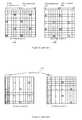
- FIG. 3is a diagram of a mapping of a cell-specific reference signal in a resource block in the case of two antenna ports at an eNB, according to the prior art.
- FIG. 4is a diagram of a resource element group allocation in a resource block in the first slot when two antenna ports are configured at an eNB, according to the prior art.
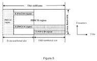
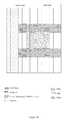
- FIG. 5is a diagram of E-PDCCH regions, according to an embodiment of the disclosure.
- FIG. 6is a table describing common search space and UE-specific search space combinations that a UE is expected to monitor, according to an embodiment of the disclosure.
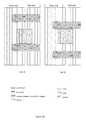
- FIG. 7is a diagram of an E-PCFICH and an E-PDCCH in the same subframe, according to an embodiment of the disclosure.
- FIG. 8is a diagram of an E-PCFICH and an E-PDCCH in different subframes, according to an embodiment of the disclosure.
- FIG. 9is a diagram of an E-PCFICH and an E-PDCCH in the same subframe, according to an embodiment of the disclosure.
- FIG. 10is a diagram of an example of predefined E-PCFICH segments in a cell, according to an embodiment of the disclosure.
- FIG. 11is a diagram of a cross-interleaving E-PDCCH region when there is no legacy PDCCH, according to an embodiment of the disclosure.
- FIG. 12is a diagram of a distribution of an E-PCFICH within a subframe, according to an embodiment of the disclosure.
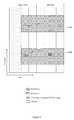
- FIG. 13is a diagram of a distribution of an E-PHICH within a subframe, according to an embodiment of the disclosure.
- FIG. 14is a diagram of REG to RE mapping in OFDM symbols configured for an E-PHICH, according to an embodiment of the disclosure.
- FIG. 15is another diagram of REG to RE mapping in OFDM symbols configured for an E-PHICH, according to an embodiment of the disclosure.
- FIG. 16is a diagram of mapping of a short REG for an E-PHICH, according to an embodiment of the disclosure.
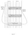
- FIG. 17is a diagram of possible options for common and UE-specific search space resource allocation, according to an embodiment of the disclosure.
- FIG. 18is a diagram of a pointer to a PDSCH of an SI-RNTI, according to an embodiment of the disclosure.
- FIG. 19is a diagram of a cross-interleaving E-PDCCH region relative to PSS/SSS/PBCH, according to an embodiment of the disclosure.
- FIG. 20is a diagram of ICIC of an E-PDCCH common search space between two neighbor cells, according to an embodiment of the disclosure.
- FIG. 21is a diagram of an eCCE index for a localized E-PDCCH transmission, according to an embodiment of the disclosure.
- FIG. 22is a diagram of a starting index of an eCCE in each E-PDCCH region, according to an embodiment of the disclosure.
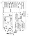
- FIG. 23is a simplified block diagram of an exemplary network element according to one embodiment.
- FIG. 24is a block diagram with an example user equipment capable of being used with the systems and methods in the embodiments described herein.
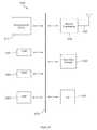
- FIG. 25illustrates a processor and related components suitable for implementing the several embodiments of the present disclosure.
- PDCCHsphysical downlink control channels
- the scheduling informationmay include a resource allocation, a modulation and coding rate (or transport block size), the identity of the intended UE or UEs, and other information.
- a PDCCHcould be intended for a single UE, multiple UEs or all UEs in a cell, depending on the nature and content of the scheduled data.
- a broadcast PDCCHis used to carry scheduling information for a physical downlink shared channel (PDSCH) that is intended to be received by all UEs in a cell, such as a PDSCH carrying system information about the eNB.
- PDSCHphysical downlink shared channel
- a multicast PDCCHis intended to be received by a group of UEs in a cell.
- a unicast PDCCHis used to carry scheduling information for a PDSCH that is intended to be received by only a single UE.
- FIG. 1illustrates a typical DL LTE subframe 110 .
- Control informationsuch as the PHICH (physical HARQ (hybrid automatic repeat request) indicator channel), PCFICH (physical control format indicator channel), and PDCCH are transmitted in a control channel region 120 .
- the PHICHis used to transmit HARQ acknowledgements and negative acknowledgements (ACK/NACK), which may indicate whether the eNB has correctly received uplink scheduled data on the physical uplink shared channel (PUSCH).
- HARQ acknowledgements and negative acknowledgementsACK/NACK
- the control channel region 120includes the first few OFDM (orthogonal frequency division multiplexing) symbols in the subframe 110 .
- the exact number of OFDM symbols for the control channel region 120may be dynamically indicated by a control format indicator (CFI) in the PCFICH, which is transmitted in the first symbol.
- CFIcontrol format indicator
- the number of OFDM symbolsmay be semi-statically configured when cross carrier scheduling is configured in the case of carrier aggregation in LTE Rel-10.
- the PDSCH, PBCH (physical broadcast channel), PSC/SSC (primary synchronization channel/secondary synchronization channel), and CSI-RS (channel state information reference signal)are transmitted in a PDSCH region 130 .
- DL user datais carried by the PDSCH channels scheduled in the PDSCH region 130 .
- Cell-specific reference signalsare transmitted over both the control channel region 120 and the PDSCH region 130 , as described in more detail below.
- Each subframe 110can include a number of OFDM symbols in the time domain and a number of subcarriers in the frequency domain.
- An OFDM symbol in time and a subcarrier in frequencytogether define a resource element (RE).
- a physical resource block(physical RB or PRB) can be defined as, for example, 12 consecutive subcarriers in the frequency domain and all the OFDM symbols in a slot in the time domain.
- An RB or PRB pair with the same RB index in slot 0 ( 140 a ) and slot 1 ( 140 b ) in a subframecan be allocated together.
- FIG. 2shows an LTE DL resource grid 210 within each slot 140 in the case of a normal cyclic prefix (CP) configuration.
- the resource grid 210is defined for each antenna port, i.e., each antenna port has its own separate resource grid 210 .
- Each element in the resource grid 210 for an antenna portis an RE 220 , which is uniquely identified by an index pair of a subcarrier and an OFDM symbol in a slot 140 .
- An RB 230includes a number of consecutive subcarriers in the frequency domain and a number of consecutive OFDM symbols in the time domain, as shown in the figure.
- An RB 230is the minimum unit used for the mapping of certain physical channels to REs 220 .
- CRSscell-specific reference signals
- FIG. 3shows an example of CRS locations in a subframe for two antenna ports 310 a and 310 b , where the RE locations marked with “R 0 ” and “R 1 ” are used for CRS port 0 and CRS port 1 transmission, respectively.
- REs marked with “X”indicate that nothing should be transmitted on those REs, as CRSs will be transmitted on the other antenna.
- REGsResource element groups
- a REGincludes either four or six consecutive REs in an OFDM symbol, depending on whether the CRSs are included.
- the REG allocation in each RBis shown in FIG. 4 , where the control region 410 includes two OFDM symbols and different REGs are indicated with different types of shading.
- REs marked with “R 0 ” or “X” in FIG. 4 a or with “R 1 ” or “X” in FIG. 4 bare reserved for CRSs for antenna port 0 and antenna port 1 , and therefore only four REs in each REG are available for carrying control channel data.
- a PDCCHcan be transmitted on an aggregation of one or more consecutive control channel elements (CCEs), where one CCE consists of, for example, nine REGs.
- CCEscontrol channel elements
- the CCEs available for a UE's PDCCH transmissionare numbered from 0 to n CCE ⁇ 1.
- the number of CCEs available in a subframedepends on the system bandwidth and the number of OFDM symbols configured for the control region. For example, in a 10 MHz system with three OFDM symbols configured for the control region and six groups configured for the PHICH, 42 CCEs are available for the PDCCH.
- Multiple PDCCHsmay be multiplexed in the control region in a subframe to support UL and DL data scheduling for one UE and to support DL and UL scheduling for more than one UE.
- the number of PDCCHs that can be supported in the control regionalso depends on the aggregation level used for each PDCCH.
- the aggregation levelindicates how many CCEs are aggregated to carry a PDCCH.
- the aggregation level for a given target packet error rateis determined by the downlink received signal quality at a UE and the size of the downlink control information (DCI) to be carried by a PDCCH.
- DCIdownlink control information
- a high aggregation levelis needed for a PDCCH intended for a UE that is at the cell edge and is far away from the serving eNB, or when a DCI with a large payload size is used.
- the legacy PDCCH region in LTEmay have capacity issues for some new applications or deployment scenarios where the number of scheduled UEs in a subframe could be large.
- Some examplesinclude multiple user multiple input multiple output (MU-MIMO) transmission, coordinated multi-point (COMP) transmission, heterogeneous network (hetnet) deployment with remote radio heads (RRHs) in a cell sharing the same cell ID, and carrier aggregation (CA).
- MU-MIMOmultiple user multiple input multiple output
- COMPcoordinated multi-point
- heterogeneous networkheterogeneous network
- RRHsremote radio heads
- CAcarrier aggregation
- E-PDCCHextended or enhanced PDCCH
- a set of RBs and OFDM symbols or PRB pairs reserved for this purposecan be referred to as an E-PDCCH region.
- the E-PDCCH region in a subframeis not necessarily completely filled with E-PDCCHs in that some resources in the E-PDCCH region not used for E-PDCCH transmission can be assigned for PDSCH transmission.
- the legacy PDCCH regionmay or may not be present in a subframe containing an E-PDCCH region.
- the time and frequency resources of an E-PDCCH regionmay be configurable. Examples of E-PDCCH regions are shown in FIG. 5 .
- E-PDCCHthe other two downlink control channels, the PHICH and the PCFICH, may also exist in extended or enhanced forms, which may be referred to as the E-PHICH and the E-PCFICH, respectively.
- E-PHICH and the E-PCFICHSeveral challenges may arise with regard to the E-PHICH and the E-PCFICH.
- E-PDCCH resource allocation in a subframe with an E-PCFICHmay need to be dynamically indicated.
- the presence of the E-PCFICHmay need to be signaled to UEs, the location of the E-PCFICH may need to be specified and signaled to UEs, the E-PCFICH may need to be multiplexed with the E-PDCCH and the PDSCH, and the information content carried by the E-PCFICH may need to be determined.
- a common search space in the E-PDCCH regionmay need to be defined.
- inter-cell interference management for the E-PCFICH, E-PHICH, and E-PDCCH common search spacemay need to be considered.
- the design and reuse of reference signals for E-PCFICH and E-PHICH demodulationmay need to be considered.
- Fifth, ACK/NACK resources in the physical uplink control channel (PUCCH) for a corresponding uplink grant transmitted by the E-PDCCHmay need to be determined.
- PUCCHphysical uplink control channel
- a common search space (CSS) and a UE-specific search space (USS) that a Rel-8/9/10 UE is expected to monitor to detect the PDCCHhave been defined.
- CCScommon search space
- USSUE-specific search space
- Another set of CSS and USSmay be defined for the E-PDCCH.
- Table 1 in FIG. 6the CSS and USS combinations that a UE is expected to monitor are shown. The table shows that there are multiple scenarios that may need a common search space for the E-PDCCH in the data region.
- the embodiments disclosed hereinmay consider the prevailing scenario where a CSS is defined in the data region. This may correspond to any scenario in Table 1 where a CSS of a data region is marked ‘Yes’. Whenever a legacy control region is mentioned, it may be assumed that the carrier is a normal carrier with CFI greater than 0.
- the CSSmay need to reside in a predefined common resource area.
- other downlink channelssuch as the E-PCFICH and the E-PHICH may be multiplexed in.
- the embodiments disclosed hereinmay cover a range of issues related to such a common resource area, including how the E-PCFICH and the E-PHICH may be multiplexed with the E-PDCCH, how the REs are allocated to the control channels, and other topics.
- Embodiments of the present disclosuremay also provide E-PDCCH/E-PHICH/E-PCFICH designs for subframes that may not contain the legacy PDCCH region.
- the embodimentsmay also enable UEs that are not capable of monitoring the legacy PHICH and PDCCH to receive control information from an eNB.
- Some embodimentsmay have a context in which the component carrier where the PDSCH is transmitted does not use cross-carrier scheduling.
- the PDSCHmay be scheduled by the control channel of the same component carrier.
- the start of the data regionmay not be obtained from the PCFICH on that component carrier, but may be configured on a semi-static basis via radio resource control (RRC) signaling.
- RRCradio resource control
- when a common search space is discussedit may be assumed that the component carrier is the primary component carrier for the UE under consideration.
- the common search spacemay only be defined for transmissions on the primary component carrier.
- An application example where the embodiments described herein may applyis the case of a new carrier type in a carrier aggregation scenario where, to reduce overhead, there is no legacy PDCCH region defined on the new carrier.
- Another application example where the embodiments may applyis in the support of machine type communication (MTC), wherein a UE may not be required to receive signals over the entire bandwidth and thus may not receive the entire legacy control region.
- MTCmachine type communication
- Another application example where the embodiments may applyis the case of a victim cell in a heterogeneous network scenario. For example, if strong interference from an aggressor cell makes it difficult to receive the signal in part of the legacy control region, then the UE may receive downlink control information via E-PDCCH/E-PHICH/E-PCFICH instead.
- a first set of embodimentsdeals with E-PCFICH resource allocation and signaling
- a second set of embodimentsdeals with E-PHICH resource allocation and configuration
- a third set of embodimentsdeals with a common search space in the E-PDCCH
- a fourth set of embodimentsdeals with coordination of E-PDCCH allocation with fixed signals
- a fifth set of embodimentsdeals with coordination in E-PDCCH allocation between neighbor cells or transmission points
- a sixth set of embodimentsdeals with PUCCH resource mapping.
- an E-PCFICHresource allocation and signaling of an E-PCFICH are provided so that an advanced UE can detect the E-PCFICH (when configured) from a predefined region without excessive delay.
- a master information blockMIB
- MIBmaster information block
- Thismay inform an advanced UE whether or not an E-PCFICH is present in a cell.
- a cell ID and/or subframe-dependent E-PCFICH resource allocation within a subframemay be predefined without any signaling.
- an E-PDCCH resource in a subframemay be signaled through an E-PCFICH in either the same subframe or a previous subframe.
- the detection of a common search space in an E-PDCCHmay be activated via RRC signaling.
- the E-PCFICHcan carry parameters that define the shared E-PDCCH control region so that the scheduling of the E-PDCCH can be changed dynamically. It may be expected that such a shared E-PDCCH control region would use cross-interleaving, where E-PDCCHs from multiple UEs are interleaved and multiplexed together. In the following discussion, such a region is referred to as a cross-interleaving region.
- the PRB pairs allocated for the E-PDCCHcannot be used by the PDSCH. This can lead to resource waste if the resources provisioned for PRBs exceed the actual E-PDCCHs to be carried for a given subframe. For example, if the subframe needs to support one UE, then at most two E-PDCCHs are needed for UE-specific signaling, one for downlink scheduling assignments, one for uplink scheduling grants. If the subframe needs to support 10 UEs, then up to 20 E-PDCCHs are needed for UE-specific signaling. Thus, the number of PRB pairs needed to support 10 UEs is much greater than the number of PRB pairs needed to support one UE.
- the E-PCFICHmay be useful to dynamically indicate the E-PDCCH allocation in each subframe based on the actual number of UEs to be scheduled. This may reduce overhead and increase overall efficiency of resource utilization.
- the E-PCFICHmay need to be detected first, independently of other information.
- the E-PCFICHmay need to be transmitted over known resources, with a known transmit format, and its resource location within a subframe may in principle be independent of the E-PDCCH allocation.
- allocating one or more PRBs or PRB pairs exclusively for the E-PCFICHmay introduce too much overhead.
- the E-PCFICHmay be multiplexed with the E-PDCCH. That is, the E-PCFICH may share some of the PRBs or PRB pairs configured for the E-PDCCH. For example, a region for interleaved E-PDCCHs can be predefined, and the E-PCFICH can be allocated to the first one or the first few OFDM symbols of the interleaved region. Additionally, the E-PCFICH can be distributed over a wide frequency range to obtain frequency diversity.
- the E-PCFICHmay need to rely on a certain type of common reference signal for channel estimation, where the reference signal can be used by multiple UEs.
- a common reference signalmay be a local common reference signal.
- the common reference signalmay be defined for the interleaved region only, which is in contrast to the CRS which is common to an entire cell covering the entire spectrum.
- These local common reference signalsmay be received as demodulation reference signals (DMRS) for the E-PCFICH by the UEs.
- DMRSdemodulation reference signals
- E-PCFICHif defined located towards the beginning of the subframe, as shown in FIG. 7 , so that the E-PCFICH can be decoded as early as possible. This may reduce the processing delay of the E-PDCCH and PDSCH decoding at the UE.
- an E-PDCCH region in a subframemay be indicated by an E-PCFICH in a previous subframe as shown in FIG. 8 .
- the E-PDCCH region in a subframemay be determined at the start of the subframe and the E-PCFICH transmitted in the previous subframe may be allocated across the whole subframe without delay concern.
- the E-PCFICH in a subframemay be used for the configuration of the E-PDCCH regions starting in the next subframe. Such an E-PDCCH configuration may be assumed for the subsequent subframes until a new E-PCFICH is detected.
- the periodicity and offset of an E-PCFICH transmissionmay be semi-statically defined, e.g., in units of subframe or radio frame.
- the UEmay attempt detection of the E-PCFICH only in certain known time instances and skip E-PCFICH detection otherwise.
- While these optionsprovide benefits such as reduced E-PCFICH overhead and having the E-PCFICH available before a subframe is received, these options may have some impact on a UE in idle or DRX mode, where a legacy UE may need to be able to detect a possible DCI within a subframe period. So to support cross-subframe resource indication, the wakeup time for an advanced UE in idle or DRX mode may need to be increased to two or more subframe durations in order for the UE to detect a DCI. Alternatively, a DCI may always be transmitted in the legacy PDCCH region for advanced UEs in idle or DRX mode. Thus, the parameters of these options may need to be selected carefully to balance the benefits and drawbacks.
- the E-PCFICHmay need to be located in predefined PRBs, possibly a subset of PRBs that are occupied by the E-PDCCH region with cross-interleaving. This is illustrated in FIG. 9 , where it is assumed that the E-PCFICH resides within two known PRB segments, each with n RBs, in the cross-interleaving E-PDCCH region. Moreover, the two known PRB segments are not contiguous in frequency so that frequency diversity can be obtained.
- integer nis smaller than or equal to half the number of total PRBs occupied by the cross-interleaving E-PDCCH region.
- FIG. 9illustrates the legacy PDCCH (assuming it exists) and the E-PHICH as well.
- the upper frequency segmentstarts at a PRB with index: ⁇ N PRB tot /2 ⁇ + ⁇ offset +N PRB segment ⁇ (( Y k mod( N PRB common /(2 ⁇ N PRB segment )))), (1) and that the lower frequency segment starts at a PRB with index: ⁇ N PRB tot /2 ⁇ offset ⁇ N PRB segment ⁇ (( Y k mod( N PRB common /(2 ⁇ N PRB segment )))+1), (2)
- N PRB segmentis the number of PRBs in a segment, and there are two segments of equal size.
- N PRB totis the total number of PRBs for the cell
- N PRB commonis the number of PRBs that can be used for the cross-interleaving region of the E-PDCCH
- N PRB common ⁇ N PRB totis a multiple of (2 ⁇ N PRB segment ).
- Variable ⁇ offsetwhere ⁇ offset ⁇ 0 and ⁇ offset ⁇ N PRB tot /2 ⁇ N PRB common /2, is the segment offset in units of PRBs, which measures the distance between the first segment and the center of the bandwidth.
- N PRB commonN PRB segment
- ⁇ offsetthe higher and lower frequency segments are guaranteed to be separated by at least 2 ⁇ offset in frequency.
- the variables needed to define the segments, N PRB common , N PRB segment , ⁇ offsetmay be predefined or provided via RRC signaling through the legacy PDCCH.
- the schemecan be two segments defined with respect to the edges of the bandwidth.
- the schemecan be N seg segments evenly spaced starting from the lower PRB index, where N seg is an integer.
- the schemecan be N seg segments evenly spaced starting from the higher PRB index.
- the cross-interleaving E-PDCCH regioncan span the entire subframe time-wise as shown in FIG. 11 .
- the presence of an enhanced control channel such as the E-PCFICHmay need to be signaled to a UE. If the legacy PDCCH is present and the UE is able to receive control information over the legacy PDCCH, the UE may receive the control signal in the legacy PDCCH region first. The presence of the E-PCFICH and its resource allocation may then be semi-statically signaled. For some UEs, such as a UE with MTC, the E-PCFICH may need to be signaled before any RRC signaling, since MTC UEs may not have the capability to detect the signal in the whole legacy control region. One possibility is for the presence of the E-PCFICH to be indicated in the MIB, which is carried over the PBCH.
- FDMfrequency division multiplexing
- TDMtime division multiplexing
- the E-PCFICHmay be allocated within one or multiple PRBs in the first slot. Only the PDSCH for advanced UEs can be multiplexed with the E-PCFICH in this case.
- E-PCFICHis transmitted in the PRBs that are also used for E-PDCCH transmission, then the multiplexing of the E-PCFICH with the PDSCH follows how the E-PDCCH is multiplexed with the PDSCH.
- E-PCFICH resourcesare predefined in common locations for all cells. In this case, no signaling is needed, but there could be inter-cell interference issues.
- E-PCFICH resourcesare predefined as a function of cell ID and perhaps subframe number. This option is illustrated in the example of FIG. 10 .
- E-PCFICH resourcesare RRC signaled. This option assumes that the legacy PDCCH is present and that all UEs are capable of receiving downlink and uplink grants in the legacy PDCCH region.
- the same E-PCFICH resource locationmay be used for all TPs in a cell.
- additional parameters and resource dimensionsmay be used, such as using code division multiplexing (CDM) to multiplex the E-PCFICHs of the TPs.
- CDMcode division multiplexing
- TP-specific parameterssuch as those related to CSI-RS configuration for the TP could be used to create shifts for the E-PCFICH resources for each TP.
- E-PCFICHE-PCFICH to REs that are adjacent to the REs for a reference signal, as shown in FIG. 12 .
- the information carried in the E-PCFICHmay be different from that in the PCFICH.
- two bitsare used to generate four states (with one state being reserved), which indicates the number of OFDM symbols for the control region.
- a full-scale resource allocationmay be needed for more flexibility. The number of bits needed depends on both bandwidth and resource allocation type. For a 20 MHz bandwidth, 25 bits are needed for resource allocation type 0/1, and 13 bits are needed for resource allocation type 2. This is quite large compared to the PCFICH, and substantial resources may be consumed in order to reach all UEs in a cell. It is effectively equivalent to sending a DCI.
- bit error rateAs the PCFICH, four to eight CCEs may be needed, similar to DCI 1A/1C transmission in the common search space of the legacy PDCCH, which is equivalent to two to three distributed RB pairs. Such resource consumption may be excessive compared to the PCFICH.
- the E-PCFICHmay take four values (e.g., 1, 2, 3, 4), each indicating a different number of PRBs relative to an anchor PRB position.
- the anchor PRBmay be either predefined or RRC signaled.
- these four valuesmay represent four states, each indicating a subset of the E-PDCCH resources configured by RRC signaling and indicating the number of PRBs and their locations.
- values of ⁇ 1, 2, 3, 4 ⁇may represent, respectively, that 1 ⁇ 4, 1 ⁇ 2, 3 ⁇ 4, or 1 portion of the E-PDCCH resources configured by RRC are used in the current subframe for the actual E-PDCCH.
- E-PCFICH values of “3” and “4”can be formulated. With such definitions, only two bits are needed, and the E-PCFICH indicates those PRBs actually used in the current subframe for the E-PDCCH, while the remaining PRBs configured by RRC may be released for PDSCH transmission.
- values of ⁇ 1, 2, 3, 4 ⁇could represent that ⁇ N 1 , N 2 , N 3 , N 4 ⁇ PRB pairs are used for the E-PDCCH, where the actual PRBs indicated by ⁇ N 1 , N 2 , N 3 , N 4 ⁇ are a function of the bandwidth.
- the PRB pairsmay be evenly spaced across the bandwidth, and their positions may be a function of the physical cell ID and/or the subframe index.
- the E-PCFICHWhile in the above it is assumed that the E-PCFICH is transmitted, the E-PCFICH does not necessarily need to be transmitted. In the absence of the E-PCFICH, a UE may need to detect the cross-interleaving E-PDCCH region via other means. For UEs or carriers with a legacy PDCCH, the presence of the E-PDCCH region as well as the resource allocation of the region may be RRC signaled, either with UE-specific RRC signaling or as a broadcast to all UEs as part of the system information blocks (SIBs).
- SIBssystem information blocks
- an E-PDCCH regionmay need to be signaled in the MIB. If an E-PDCCH region is present, a predefined common search space within the E-PDCCH region may be used for transmitting all the downlink and uplink grants until a UE is configured with the rest of the E-PDCCH region for a UE-specific search space.
- this set of embodimentsprovides for transmitting a first downlink control channel over a first set of resource elements that are frequency-division multiplexed with downlink data channels and interleaved with a second set of resource elements.
- the second set of resource elementscarries a second downlink control channel.
- the first downlink control channelcarries configuration information for a second downlink control channel.
- the first set of resource elementsmay be known to a plurality of UEs.
- an E-PCFICH channelis introduced in LTE to dynamically indicate the resource allocation of an E-PDCCH with a distributed transmission.
- the presence of an E-PCFICHmay be indicated by an existing reserved bit in the MIB carried by the PBCH.
- the resources for the E-PCFICHmay be predefined and known to a UE and may share a subset of PRB pairs configured for the E-PDCCH.
- the PRB pairs that contain the E-PCFICHmay be FDM multiplexed with the PDSCH, and the locations of such PRB pairs may vary from cell to cell.
- the resources for the E-PCFICHmay be allocated in the first slot of a subframe and may be close to the reference signals.
- the content of the E-PCFICHmay consist of a bit string representing one of a number of predefined resource configurations.
- the E-PDCCH resource configuration indicated by the E-PCFICHmay be for an E-PDCCH transmitted in the same subframe or for an E-PDCCH transmitted in a different subframe, such as a subsequent subframe.
- a second set of embodiments disclosed hereindeals with E-PHICH resource allocation and configuration for achieving good channel estimation performance.
- the E-PHICHis mapped to REs close to DMRS REs.
- REG-to-RE mappingis provided to achieve transmit diversity of the E-PHICH.
- E-PDCCHWith the introduction of the E-PDCCH, there may be a need to provide a high capacity to carry a large number of ACK/NACKs. Therefore, there may be a need to enhance the PHICH channel that carries ACK/NACKs. Such an enhanced PHICH channel can be referred to as an E-PHICH channel. Enhancement of the PHICH may be especially necessary considering uplink MU-MIMO and applications such as MTC. Unlike the relay backhaul link, the downlink ACK/NACK signal cannot be replaced by an uplink new or retransmission grant exclusively without a dedicated ACK/NACK channel, such as the PHICH, since a UE may not have relatively constant downlink data.
- the resource allocation requirements for the E-PHICHmay need to be carefully selected in order for robust performance of the E-PHICH to be maintained.
- the E-PHICHis distributed to OFDM symbols containing or near the local common DMRS or to OFDM symbols adjacent thereto.
- REs adjacent to the REs used for reference signal transmissionmay be allocated to carry downlink control information where high reliability is desired, such as the E-PHICH, since REs close to reference signals tend to have more reliable channel estimation information. As illustrated in FIG. 13 , this may ensure good channel estimation performance for the E-PHICH.
- each E-PHICH groupoccupies 12 REs, assuming a normal cyclic prefix.
- each PRBcan transmit four E-PHICH groups. The same number of E-PHICH groups may be defined as for the PHICH.
- N PHICH group⁇ N g ( N RB DL /8) ⁇ , for normal cyclic prefix (4)
- N PHICH groupis the number of PHICH groups and N g is a variable provided by higher layers.
- N PHICH groupthe number of PRBs the E-PHICH occupies.
- subframes # 0 and # 5need twice as many E-PHICH groups as otherwise.
- the fraction of PRBs occupied by the E-PHICHis 1 ⁇ 8, which is still sufficient to avoid interference between two neighbor cells.
- each PRBcan transmit three E-PHICH groups for a normal cyclic prefix.
- the fraction of PRBs that need to be assigned to carry the E-PHICHis approximately N g /24, which is not excessive.
- the demodulation of the E-PHICHmay have to rely on reference signals shared by multiple UEs, such as un-precoded DMRS. This may make it difficult to multiplex the E-PHICH with other types of transmissions that use UE-specific reference signals, such as a PDSCH with beamforming or a UE-specific E-PDCCH.
- the E-PHICHcan be easily multiplexed with an E-PDCCH that uses a shared reference signal that is of a cross-interleaved type and can carry common information. Even when a common search space does not exist in a subframe, there can still be UE-specific E-PDCCHs that are cross-interleaved and use a shared reference signal.
- an REGmay be defined in each OFDM symbol allocated for the E-PHICH.
- the same REG definition as in Rel-8may be used. That is, an REG is composed of four consecutively available REs in one OFDM symbol in an RB configured for a potential E-PHICH, where an RE is assumed to be unavailable with respect to the mapping of the E-PHICH if it is used for transmission of CRS. If CRS is configured for port 0 , it may be assumed that REs for transmission of CRS port 1 are also unavailable for the REG.
- Precoded transmit diversity (TxD) symbols for 2-tx and 4-tx as defined in Rel-8may be mapped within each REG.
- REG definitionIn OFDM symbols containing DMRS and/or CSI-RS, the options described below may be used for REG definition.
- the REGs used for a particular downlink channele.g., E-PHICH
- a predefined rulesuch as a rule defined in Rel-8.
- An REGis composed of four consecutively available REs in one OFDM symbol in an RB configured for potential E-PHICH transmission counted in ascending order of subcarriers.
- An REis assumed to be unavailable with respect to mapping the E-PHICH if the RE is configured for transmission of a DMRS or if the RE is configured for a CSI-RS.
- RE(k 1 ) and RE(k 2 )are adjacent REs, as are RE(k 3 ) and RE(k 4 ).
- This conditionmay ensure that the propagation channels are approximately the same for each of the RE pairs, which is desirable for transmit diversity.
- FIG. 14One such example is shown in FIG. 14 .
- This kind of mappingmay be appropriate for the space frequency block code (SFBC) type of transmit diversity.
- SFBCspace frequency block code
- CSI-RSis not included in FIG. 14 , the same principle may apply for a subframe containing a CSI-RS.
- the propagation channels over an REGshould be approximately the same.
- further restrictionsmay be applied to an REG, such as k 4 ⁇ k 1 ⁇ 5.
- an REGis composed of four neighboring available REs in an RB in two consecutive OFDM symbols containing a DMRS and/or a CSI-RS counted in ascending order of OFDM symbols first and then subcarriers.
- An REis assumed to be unavailable with respect to mapping the E-PHICH if the RE is used for the transmission of a reference signal such as a DMRS or a CSI-RS.
- RE 1 and RE 2are adjacent REs, either in the frequency domain or the time domain;
- RE 3 and RE 4are adjacent REs, either in the frequency domain or the time domain; and the maximum separation of the REs within an REG in the frequency domain is five REs.
- the space time block code (STBC) type of transmit diversitymay be needed in the OFDM symbols containing a DMRS and/or a CSI-RS, so a hybrid transmit diversity with SFBC and STBC may be needed.
- STBCspace time block code
- E-PHICHsmay be multiplexed, scrambled, modulated, mapped to layers, and precoded in the same way as for the legacy PHICH except that transmit diversity uses DMRS ports for demodulation instead of CRS ports.
- the DMRSs in those RBsare shared by multiple UEs and thus should not be precoded.
- the legacy DMRSis used as an example for E-PDCCH and E-PHICH demodulation.
- new demodulation reference signalsmay be defined for the E-PDCCH and the E-PHICH.
- the reference symbols for cross-interleaving the E-PDCCH regionmay need to be known to multiple UEs. That is, the reference symbols may not be specific to a single UE. Unlike a conventional CRS, these shared reference signals are only local common reference signals and do not need to be transmitted across the entire bandwidth.
- the shared reference signalsmay be TP-specific, so that all UEs attached to a same TP can access the E-PDCCH common search space specific to the given TP.
- Channel-independent precodingmay be assumed by the UE for these shared reference signals.
- REGs of four REs for the PHICHmay make it easy to support 4-tx TxD. This may also lead to the use of an orthogonal covering code (OCC) with a length of 4 to separate ACK/NACK signals in a CDM fashion in each PHICH group.
- OCCorthogonal covering code
- the PDCCH, the PHICH, and the PCFICHuse the same REG as the basic unit and are all transmitted in the legacy PDCCH region, so it may be easy to map these kinds of REGs to the physical time-frequency resource grid.
- the E-PHICHmay be transmitted in the PDSCH region. Therefore, it may not be easy to map an REG of four REs to the physical time-frequency resource grid because the REs that are already used for other purposes, such as a DMRS or a CSI-RS, may need to be skipped. As seen from FIG. 14 , some REs in an REG may be separated too far from each other after mapping, which may cause performance degradation due to the loss of orthogonality among OCC in the case of a highly frequency selective channel. To solve this issue, instead of using four REs per REG as discussed above, a modified E-PHICH group with a smaller size of REGs may be defined, where the new REG consists of two REs instead of four. Length- 2 OCC may then be applied to each E-PHICH in an E-PHICH group in each of the three REGs. Either 2-tx or 4-tx transmit diversity with SFBC+FSTD may still be used.
- the modified E-PHICH groupconsists of three REGs each with two REs, so each E-PHICH group could multiplex four ACK/NACK bits.
- the size of each E-PHICH groupis reduced by half as compared with a Rel-8 PHICH group, so for the same given RE resources, the number of E-PHICH groups is doubled. This could maintain the overall E-PHICH capacity unchanged.
- the decoding of the E-PHICHmay use the DMRS ports, and using two DMRS ports to support 2-tx TxD would cut the DMRS overhead by half as compared with using four DMRS ports to support 4-tx TxD.
- the performance gain of 4-tx TxD over 2-tx TxD as observed for a Rel-8 PDCCHis less than 1 dB, and this gain could be offset by the overhead reduction and other benefits of using 2-tx TxD.
- a smaller size REG for an E-PHICH groupmay avoid the loss of orthogonality of OCCs in certain REGs with four REs due to large separations of REs.
- FIG. 16shows some examples of mapping such smaller size of REGs to the time-frequency grid, where “1” and “2” indicate the first and second REs in an REG. Compared with FIG. 14 , there are no occasions where the REs in an REG are separated by two to three reserved REs.
- this set of embodimentsprovides for multiplexing the HARQ response signals of a plurality of UEs over the same time-frequency resources.
- the same time-frequency resourcesare frequency-division multiplexed with a data transmission.
- Configuration information regarding the time-frequency resourcesis signaled to the plurality of UEs before a HARQ response signal is transmitted.
- the resources used for E-PHICH transmissionmay be allocated close to the DMRS ports for more accurate channel estimation.
- the REGs for the E-PHICHmay be defined by consecutive REs on the same OFDM symbols or by neighboring REs on two consecutive OFDM symbols.
- the number of REs in each REGmay be two or four.
- 2-tx or 4-tx transmit diversity schemesmay be used to transmit the E-PHICH. While here an REG of size 2 or 4 has been used as an example of a resource allocation unit, other resource units can be used as well. For example, a size of m by n rectangle in the time-frequency grid can be used as a resource allocation unit, where m and n are integers greater than or equal to 1.
- transmit diversityhas been used as an example of a MIMO scheme, other schemes such as beamforming, spatial multiplexing, MU-MIMO can be used instead.
- a third set of embodiments disclosed hereindeals with a common search space over the E-PDCCH.
- a common search spaceis supported in an E-PDCCH region with cross-interleaving operation.
- DCIs with the cyclic redundancy check (CRC) scrambled by a system information radio network temporary identifier (SI-RNTI)are transmitted in both the legacy PDCCH and the E-PDCCH.
- DCIs with the CRC scrambled by a paging or random access channel RNTI (P-/RA-RNTI)are sent over the legacy PDCCH for legacy UEs and over a common search space in the E-PDCCH region for advanced UEs.
- CRCcyclic redundancy check
- SI-RNTIsystem information radio network temporary identifier
- P-/RA-RNTIpaging or random access channel RNTI
- the common search space of the E-PDCCHmay start immediately after the legacy control region.
- the number of OFDM symbols in the legacy control regionis indicated by a control channel indicator (CFI) carried by the PCFICH.
- CFIcontrol channel indicator
- the common search spacemay always start at a preconfigured OFDM symbol, such as OFDM symbol # 3 (assuming the OFDM symbol index in a subframe starts at 0).
- Both a common search space and a UE-specific search spacemay need to be defined over the E-PDCCH.
- the resources for the common search space in the E-PDCCHmay not overlap with the resources for the UE-specific search space.
- separate resourcese.g., PRBs
- two E-PDCCH regionsare defined and a UE searches each region for common and UE-specific DCIs.
- a benefit of this optionis that UE-specific DCI detection could be simpler, since only one E-PDCCH region may need to be monitored for that purpose.
- a drawbackis that if the resource allocation for the common search space is predefined or semi-statically allocated, some of the resources may be wasted if there is no common DCI to send.
- the resources for the common search space in the E-PDCCHmay overlap with the resources for the UE-specific search space. That is, a single E-PDCCH region may be defined for both search space types. In this case, better resource utilization may be achieved for the common search space.
- DCIsare cross-interleaved and the PRBs are predefined or semi-statically signaled, overhead could increase if few DCIs need to be sent.
- two E-PDCCH regionsmay be present in a subframe.
- One E-PDCCH regionmay be for a localized transmission that is exclusively for the UE-specific search space.
- Another E-PDCCH regionmay be a distributed region shared by both the common search space and the UE-specific search space.
- a UEmay be configured to search in both the regions for UE-specific DCIs and common DCIs. In this case, better resource utilization may be expected compared with the first and second options, even with semi-static resource allocation for the common search space, but possibly at the cost of increased UE implementation complexity.
- the resource for the common search space in the E-PDCCH regionis predefined and known.
- there are two E-PDCCH regions in a subframeone with distributed transmission where DCIs may be cross-interleaved and the other with localized transmission where DCIs are not cross-interleaved.
- the distributed transmission regionmay be exclusively for the common search space, where multiple DCIs may be cross-interleaved.
- the PRBs for the distributed transmission regionmay be either predefined or signaled through the E-PCFICH.
- the UE-specific search spacemay be exclusively in the localized transmission region.
- different DCIs in the UE-specific search spacemay be multiplexed in either the PRB/PRB pair level or the sub-PRB/PRB pair level.
- the second optiononly one E-PDCCH region with distributed transmission is present in a subframe.
- the regionmay be predefined or signaled through the E-PCFICH. All DCIs may be cross-interleaved.
- the common search spacemay occupy a known subset of the total resources, and the resources for the common search space may also be overlapped with the UE-specific search space.
- the distributed regionmay also be shared by the common search space and the UE-specific search space.
- the resource for the common search spacemay be predefined.
- both the legacy PDCCH region and the E-PDCCH common search spaceare present, there could be confusion about where the UEs should search for the common information whose CRC is scrambled by a SI-RNTI, P-RNTI, or RA-RNTI. Since an SI-RNTI is common between legacy UEs and advanced UEs, the common information may need to be transmitted over the legacy PDCCH region. This information may be repeated in the E-PDCCH common search space if an advanced UE (e.g., MTC) cannot or will not detect the legacy PDCCH region. Only one PDSCH carrying a given system information payload is transmitted in a subframe (i.e., not repeated). Only the pointer to the PDSCH is repeated. This is shown in FIG. 18 .
- the paging and random access-related messagesmay be divided into at least three scenarios.
- some UEsmay be defined to receive the common information in the legacy PDCCH region only. This set of UEs may include all legacy UEs (Rel-10 or earlier).
- some UEsmay be defined to receive the common information in the E-PDCCH common search space only. This set of UEs may include all MTC types of UEs.
- the differentiationmay be performed in a relatively straightforward manner by the scheduler.
- some UEsmay be configured to receive the common information in either the common search space in the legacy PDCCH or the common search space in the E-PDCCH. For example, if the common search space in the E-PDCCH is not configured, the UE may search the common search space in the legacy PDCCH region. Otherwise, the UE may search the common search space in the E-PDCCH region.
- Such UEsmay include UEs in Rel-11 and beyond.
- a UE capable of detecting DCIs in a common search space in both the legacy PDCCH and the E-PDCCHmay need to understand whether or not to search a common search space in an E-PDCCH region.
- a common search spaceis always present within the E-PDCCH region, so no signaling is required to indicate the need to detect the common search space over the E-PDCCH. This may be unavoidable if the network needs to serve MTC UEs that may not have access to the entire legacy control region.
- detecting or not detecting the common search space in the E-PDCCHmay be configured by RRC signaling. That is, a UE may be RRC signaled through the legacy PDCCH about whether to perform a search in a common search space in the E-PDCCH region.
- a UEmay obtain all the system information in the downlink and, after successful access, may be informed about the UE-specific E-PDCCH configuration through RRC signaling. Before being informed about the UE-specific E-PDCCH configuration, a UE may have to depend on the legacy PDCCH for receiving all downlink and uplink grants.
- both common and UE-specific search spacesmay need to be present in a subframe.
- PRBs or PRB pairs for the common search spacemay be either dynamically indicated through the E-PCFICH or predefined.
- the resources for the common search space within the PRBs/PRB pairsmay be predefined.
- PRBs/PRB pairs for a UE-specific search spacemay be the same as the PRBs/PRB pairs for the common search space or may be different. When different PRBs/PRB pairs are used, the PRBs/PRB pairs may need to be predefined.
- Single antenna transmission or transmit diversitymay be configured for a common search space.
- the antenna number for a common search space transmissionmay be derived from broadcast information such as the PBCH or may be RRC configured if the antenna number is different from that used for the legacy PDCCH. Therefore, no explicit signaling may be needed to inform the UE which transmission mode is used for a common search in the E-PDCCH.
- the common search spacecould be transmitted over a number of distributed resources, e.g., one, two or four PRBs, across the frequency.
- either a transmit diversity scheme or random beamformingmay be applied in the common search space transmission to further exploit diversity gain.
- this set of embodimentsprovides for transmitting a downlink control channel by frequency-division multiplexing with downlink data channels.
- a time-frequency resource that can be occupied by the downlink control channelis known to a plurality of UEs and varies from a first time interval to a second time interval.
- the downlink control channelmay carry information associated with the SI-RNTI, the P-RNTI, the RA-RNTI, or the C-RNTI.
- a common search spacemay be defined and configured in the E-PDCCH.
- the common search space in the E-PDCCHmay or may not overlap with the UE-specific search space.
- the common search spacemay overlap with the distributed UE-specific search space.
- the common search spacemay be used to carry system messages and UE-specific messages.
- a UEmay be configured to monitor one common search space in either the legacy PDCCH or the E-PDCCH.
- the common search spacemay be present in all E-PDCCHs or the common search space may be configured by higher-layer signaling such as RRC signaling.
- the common search spacemay be transmitted over a number of distributed resources.
- a transmit diversity schememay be used, with the antenna number being derived either from the PBCH or from RRC signaling.
- a fourth set of embodiments disclosed hereindeals with coordination of E-PDCCH allocation with fixed signals, such as the primary synchronization signal (PSS), secondary synchronization signal (SSS), and PBCH.
- PSSprimary synchronization signal
- SSSsecondary synchronization signal
- PBCHPBCH
- the cross-interleaving E-PDCCH search regionmay need to coexist with the PSS/SSS/PBCH in a same subframe.
- PRBs for a common search spaceare allocated immediately above and immediately below the PSS/SSS/PBCH, as shown in FIG. 19 .
- the PRBs for the cross-interleaving E-PDCCH regionmay be any PRBs that do not contain existing signals and channels such as PSS/SSS or PBCH.
- this set of embodimentsprovides for transmitting a common signal over a set of predefined frequency resources and transmitting a shared downlink control channel over a second set of frequency resources.
- the second set of frequency resourcesmay be non-overlapping with the predefined frequency resources when the shared downlink control channel is transmitted simultaneously with the common signal.
- the common signalmay be a synchronization signal or a physical broadcast channel.
- the shared downlink control channelmay be an E-PCFICH, an E-PHICH, or an E-PDCCH.
- a fifth set of embodiments disclosed hereindeals with coordination in E-PDCCH allocation between neighbor cells or transmission points.
- Inter-cell interference coordinationmay be a motivator in defining the enhanced downlink control channels.
- different cellsallocate the E-PCFICH and the E-PHICH in non-overlapping resource blocks as much as possible to achieve interference avoidance and/or interference randomization. Additionally or alternatively, different cells map the E-PCFICH and the E-PHICH to non-overlapping resource elements as much as possible to achieve interference avoidance and/or interference randomization.
- the resources allocated to the E-PCFICH, the E-PHICH, and the cross-interleaving E-PDCCH regionmay be communicated to neighbor cells for interference avoidance purposes.
- E-PDCCHover the legacy PDCCH is the possibility for better coordination of interference between adjacent cells. To optimize performance, it may be desirable to avoid allocating the same PRBs to the cross-interleaving E-PDCCH of adjacent cells.
- three sets of non-overlapping resourcesare defined, each corresponding to the cell ID carried by the primary synchronization signal of the cell. This is illustrated with an example in FIG. 20 .
- interference randomizationis used in conjunction with interference avoidance.
- the cross-interleaving regionmay be a pseudo-random function of the physical cell ID and the subframe index. Even if two neighbor cells happen to overlap in one subframe, they are unlikely to overlap in the next subframe.
- the resource unitsmay be shifted based on the cell ID (or TP ID or CSI-RS resource associated with the TP). Such a shift may protect the E-PCFICH and, more importantly, the E-PHICH, and may avoid the collision of such channels from neighbor cells or TPs. For example, indices of the REGs that the E-PCFICH and the E-PHICH occupy may be generated with a function of cell ID.
- the resources allocated to the E-PCFICH, the E-PHICH, and the cross-interleaving E-PDCCH regionmay be communicated to neighbor cells via the X2 interface for interference coordination purposes.
- this set of embodimentsprovides for transmitting a first shared downlink control channel from a first time-frequency resource by a first transmission point and transmitting a second shared downlink control channel from a second time-frequency resource by a second transmission point.
- the first shared downlink control channel and the second downlink control channelmay carry the same downlink control information.
- Non-overlapping of the first time-frequency resource with the second time-frequency resourcemay be achieved by coordinating the transmissions of the first and the second transmission points.
- the same downlink control informationmay be a HARQ-ACK response or configuration information of another downlink control channel.
- the coordinatingmay be performed by a base station or other access node that is connected to both the first transmission point and the second transmission point.
- the coordinatingmay be performed by exchanging information between the first transmission point and the second transmission point.
- resources for the E-PDDCH, E-PCFICH and E-PHICH from different cellsmay be shifted based on the cell ID or other TP-related parameters (e.g., TP ID) to avoid collisions and mitigate interference.
- TP-related parameterse.g., TP ID
- a sixth set of embodiments disclosed hereindeals with PUCCH resource mapping.
- the resource used to transmit a HARQ ACK/NACK over the PUCCHis linked to the index of the first CCE of the corresponding PDCCH carrying the downlink grant. If the E-PDCCH is introduced, this implicit relationship may need to be re-evaluated.
- implicit indication of PUCCH resources via E-PDCCH resourcesis provided.
- the index of the first resource unit of the E-PDCCHmay be used to indicate the PUCCH resource. If multiple E-PDCCH regions are configured, the index of the starting resource unit of each region may be signaled to a UE to ensure that the UE can generate a distinct PUCCH resource for each corresponding E-PDCCH.
- E-PDCCH transmissionTwo types may be supported.
- Oneis localized transmission, where the E-PDCCH for a UE occupies contiguous resources within an E-PDCCH region.
- the otheris distributed transmission, where an E-PDCCH occupies non-contiguous resources and E-PDCCHs for multiple UEs are multiplexed and transmitted from the same set of PRBs or PRB pairs.
- the mapping between the CCE index and the PUCCH resourcecould be reused.
- the implicit mapping relation between the CCE index and the PUCCH resourcemay need to be redefined.
- a new resource unitmay be used, which consists of a subset of the resource elements in a PRB pair.
- a unitcan be referred to as an eCCE (enhanced CCE).
- eCCEenhanced CCE
- their eCCEsmay be arranged in a queue and assigned with indices in ascending order. In this case, the UE may still use the first eCCE index of an E-PDCCH to generate a resource for its corresponding PUCCH transmission.
- an offset for a regionmay be signaled to a UE, which may be configured to search this region for its E-PDCCH. This is illustrated in FIG. 22 .
- the UEmay use the sum of the offset and the index of the first eCCE of an E-PDCCH to derive the corresponding PUCCH resource index.
- the UEmay use the sum of the offset and the index of the last eCCE of an E-PDCCH to derive the corresponding PUCCH resource index.
- the offset of each E-PDCCH regionmay be selected such that all the corresponding PUCCH resource indices for the region are not overlapped with the PUCCH resource indices for other E-PDCCH regions and the legacy PDCCH region.
- the offsetsmay be sent semi-statically to the UE using higher layer signaling as part of the UE E-PDCCH configuration.
- the PUCCH resource for transmitting ACK/NACK signalsmay be implicitly linked to an eCCE index of the corresponding E-PDCCH.
- the embodiments disclosed hereinprovide a detailed design of the E-PCFICH, the E-PHICH, and the common search space of the E-PDCCH. Signaling procedures for the enhanced control channels are described, as is resource allocation within a subframe, taking into consideration the DMRS distribution. Inter-cell interference management of the common control channels is also taken into account. PUCCH resource mapping procedures for the E-PDCCH are provided and embodiments are disclosed that allow PUCCH resource generation in an implicit way.
- network element 3110includes a processor 3120 and a communications subsystem 3130 , where the processor 3120 and communications subsystem 3130 cooperate to perform the methods described above.
- UE 3200may comprise a two-way wireless communication device having voice and data communication capabilities. In some embodiments, voice communication capabilities are optional.
- the UE 3200generally has the capability to communicate with other computer systems on the Internet.
- the UE 3200may be referred to as a data messaging device, a two-way pager, a wireless e-mail device, a cellular telephone with data messaging capabilities, a wireless Internet appliance, a wireless device, a smart phone, a mobile device, or a data communication device, as examples.
- the UE 3200may incorporate a communication subsystem 3211 , including a receiver 3212 and a transmitter 3214 , as well as associated components such as one or more antenna elements 3216 and 3218 , local oscillators (LOs) 3213 , and a processing module such as a digital signal processor (DSP) 3220 .
- the particular design of the communication subsystem 3211may be dependent upon the communication network in which the UE 3200 is intended to operate.
- Network access requirementsmay also vary depending upon the type of network 3219 .
- network accessis associated with a subscriber or user of the UE 3200 .
- the UE 3200may require a removable user identity module (RUIM) or a subscriber identity module (SIM) card in order to operate on a network.
- RUIMremovable user identity module
- SIMsubscriber identity module
- the SIM/RUIM interface 3244is typically similar to a card slot into which a SIM/RUIM card may be inserted.
- the SIM/RUIM cardmay have memory and may hold many key configurations 3251 and other information 3253 , such as identification and subscriber-related information.
- the UE 3200may send and receive communication signals over the network 3219 .
- the network 3219may consist of multiple base stations communicating with the UE 3200 .
- Signals received by antenna 3216 through communication network 3219are input to receiver 3212 , which may perform such common receiver functions as signal amplification, frequency down conversion, filtering, channel selection, and the like.
- Analog to digital (A/D) conversion of a received signalallows more complex communication functions, such as demodulation and decoding to be performed in the DSP 3220 .
- signals to be transmittedare processed, including modulation and encoding for example, by DSP 3220 and are input to transmitter 3214 for digital to analog (D/A) conversion, frequency up conversion, filtering, amplification, and transmission over the communication network 3219 via antenna 3218 .
- DSP 3220not only processes communication signals but also provides for receiver and transmitter control. For example, the gains applied to communication signals in receiver 3212 and transmitter 3214 may be adaptively controlled through automatic gain control algorithms implemented in DSP 3220 .
- the UE 3200generally includes a processor 3238 which controls the overall operation of the device. Communication functions, including data and voice communications, are performed through communication subsystem 3211 . Processor 3238 also interacts with further device subsystems such as the display 3222 , flash memory 3224 , random access memory (RAM) 3226 , auxiliary input/output (I/O) subsystems 3228 , serial port 3230 , one or more keyboards or keypads 3232 , speaker 3234 , microphone 3236 , other communication subsystem 3240 such as a short-range communications subsystem, and any other device subsystems generally designated as 3242 . Serial port 3230 may include a USB port or other port currently known or developed in the future.
- Some of the illustrated subsystemsperform communication-related functions, whereas other subsystems may provide “resident” or on-device functions.
- some subsystemssuch as keyboard 3232 and display 3222 , for example, may be used for both communication-related functions, such as entering a text message for transmission over a communication network, and device-resident functions, such as a calculator or task list.
- Operating system software used by the processor 3238may be stored in a persistent store such as flash memory 3224 , which may instead be a read-only memory (ROM) or similar storage element (not shown).
- ROMread-only memory
- the operating system, specific device applications, or parts thereof,may be temporarily loaded into a volatile memory such as RAM 3226 .
- Received communication signalsmay also be stored in RAM 3226 .
- flash memory 3224may be segregated into different areas for both computer programs 3258 and program data storage 3250 , 3252 , 3254 and 3256 . These different storage types indicate that each program may allocate a portion of flash memory 3224 for their own data storage requirements.
- Processor 3238in addition to its operating system functions, may enable execution of software applications on the UE 3200 .
- a predetermined set of applications that control basic operations, including at least data and voice communication applications for example,may typically be installed on the UE 3200 during manufacturing. Other applications may be installed subsequently or dynamically.
- the computer-readable storage mediummay be tangible or in a transitory/non-transitory medium such as optical (e.g., CD, DVD, etc.), magnetic (e.g., tape), or other memory currently known or developed in the future.
- opticale.g., CD, DVD, etc.
- magnetice.g., tape
- other memorycurrently known or developed in the future.
- One software applicationmay be a personal information manager (PIM) application having the ability to organize and manage data items relating to the user of the UE 3200 such as, but not limited to, e-mail, calendar events, voice mails, appointments, and task items.
- PIMpersonal information manager
- One or more memory storesmay be available on the UE 3200 to facilitate storage of PIM data items.
- Such a PIM applicationmay have the ability to send and receive data items via the wireless network 3219 .
- Further applicationsmay also be loaded onto the UE 3200 through the network 3219 , an auxiliary I/O subsystem 3228 , serial port 3230 , short-range communications subsystem 3240 , or any other suitable subsystem 3242 , and installed by a user in the RAM 3226 or a non-volatile store (not shown) for execution by the processor 3238 .
- Such flexibility in application installationmay increase the functionality of the UE 3200 and may provide enhanced on-device functions, communication-related functions, or both.
- secure communication applicationsmay enable electronic commerce functions and other such financial transactions to be performed using the UE 3200 .
- a received signalsuch as a text message or web page download may be processed by the communication subsystem 3211 and input to the processor 3238 , which may further process the received signal for output to the display 3222 , or alternatively to an auxiliary I/O device 3228 .
- a user of the UE 3200may also compose data items, such as email messages for example, using the keyboard 3232 , which may be a complete alphanumeric keyboard or telephone-type keypad, among others, in conjunction with the display 3222 and possibly an auxiliary I/O device 3228 . Such composed items may then be transmitted over a communication network through the communication subsystem 3211 .
- UE 3200For voice communications, overall operation of the UE 3200 is similar, except that received signals may typically be output to a speaker 3234 and signals for transmission may be generated by a microphone 3236 .
- Alternative voice or audio I/O subsystemssuch as a voice message recording subsystem, may also be implemented on the UE 3200 .
- voice or audio signal outputmay be accomplished primarily through the speaker 3234
- display 3222may also be used to provide an indication of the identity of a calling party, the duration of a voice call, or other voice call-related information, for example.
- Serial port 3230may be implemented in a personal digital assistant (PDA)-type device for which synchronization with a user's desktop computer (not shown) may be desirable, but such a port is an optional device component.
- PDApersonal digital assistant
- Such a port 3230may enable a user to set preferences through an external device or software application and may extend the capabilities of the UE 3200 by providing for information or software downloads to the UE 3200 other than through a wireless communication network.
- the alternate download pathmay, for example, be used to load an encryption key onto the UE 3200 through a direct and thus reliable and trusted connection to thereby enable secure device communication.
- Serial port 3230may further be used to connect the device to a computer to act as a modem.
- Other communications subsystems 3240are further optional components which may provide for communication between the UE 3200 and different systems or devices, which need not necessarily be similar devices.
- the subsystem 3240may include an infrared device and associated circuits and components or a BluetoothTM communication module to provide for communication with similarly enabled systems and devices.
- Subsystem 3240may further include non-cellular communications such as WiFi, WiMAX, near field communication (NFC), and/or radio frequency identification (RFID).
- RFIDradio frequency identification
- the other communications element 3240may also be used to communicate with auxiliary devices such as tablet displays, keyboards or projectors.
- FIG. 25illustrates an example of a system 3300 that includes a processing component 3310 suitable for implementing one or more embodiments disclosed herein.
- the system 3300might include network connectivity devices 3320 , random access memory (RAM) 3330 , read only memory (ROM) 3340 , secondary storage 3350 , and input/output (I/O) devices 3360 .
- RAMrandom access memory
- ROMread only memory
- secondary storage 3350secondary storage
- I/Oinput/output
- These componentsmight communicate with one another via a bus 3370 . In some cases, some of these components may not be present or may be combined in various combinations with one another or with other components not shown.
- DSPdigital signal processor
- the processor 3310executes instructions, codes, computer programs, or scripts that it might access from the network connectivity devices 3320 , RAM 3330 , ROM 3340 , or secondary storage 3350 (which might include various disk-based systems such as hard disk, floppy disk, or optical disk). While only one CPU 3310 is shown, multiple processors may be present. Thus, while instructions may be discussed as being executed by a processor, the instructions may be executed simultaneously, serially, or otherwise by one or multiple processors.
- the processor 3310may be implemented as one or more CPU chips.
- the network connectivity devices 3320may take the form of modems, modem banks, Ethernet devices, universal serial bus (USB) interface devices, serial interfaces, token ring devices, fiber distributed data interface (FDDI) devices, wireless local area network (WLAN) devices, radio transceiver devices such as code division multiple access (CDMA) devices, global system for mobile communications (GSM) radio transceiver devices, universal mobile telecommunications system (UMTS) radio transceiver devices, long term evolution (LTE) radio transceiver devices, worldwide interoperability for microwave access (WiMAX) devices, and/or other well-known devices for connecting to networks.
- CDMAcode division multiple access
- GSMglobal system for mobile communications
- UMTSuniversal mobile telecommunications system
- LTElong term evolution
- WiMAXworldwide interoperability for microwave access
- These network connectivity devices 3320may enable the processor 3310 to communicate with the Internet or one or more telecommunications networks or other networks from which the processor 3310 might receive information or to which the processor 3310 might output information.
- the network connectivity devices 3320might also include one or more transceiver components 3325 capable of transmitting and/or receiving data wirelessly.
- the RAM 3330might be used to store volatile data and perhaps to store instructions that are executed by the processor 3310 .
- the ROM 3340is a non-volatile memory device that typically has a smaller memory capacity than the memory capacity of the secondary storage 3350 . ROM 3340 might be used to store instructions and perhaps data that are read during execution of the instructions. Access to both RAM 3330 and ROM 3340 is typically faster than to secondary storage 3350 .
- the secondary storage 3350is typically comprised of one or more disk drives or tape drives and might be used for non-volatile storage of data or as an over-flow data storage device if RAM 3330 is not large enough to hold all working data. Secondary storage 3350 may be used to store programs that are loaded into RAM 3330 when such programs are selected for execution.
- the I/O devices 3360may include liquid crystal displays (LCDs), touch screen displays, keyboards, keypads, switches, dials, mice, track balls, voice recognizers, card readers, paper tape readers, printers, video monitors, or other well-known input/output devices.
- the transceiver 3325might be considered to be a component of the I/O devices 3360 instead of or in addition to being a component of the network connectivity devices 3320 .
- 3GPP TS 36.2113GPP TS 36.212
- 3GPP TS 36.2133GPP TS 36.331.
- a method for communication in a wireless telecommunication systemcomprises transmitting, by a network element, a downlink control channel over a set of resource elements, wherein the downlink control channel carries at least one parameter that configures a control channel region, and wherein the control channel region is frequency-division multiplexed with a downlink data channel.
- a network elementcomprises a processor configured such that the network element transmits a downlink control channel over a set of resource elements, wherein the downlink control channel carries at least one parameter that configures a control channel region, and wherein the control channel region is frequency-division multiplexed with a downlink data channel.
- a method for communication in a wireless telecommunication systemcomprises mapping, by a network element, signals of a HARQ-ACK response to a plurality of resource elements, wherein resource blocks containing signals of the HARQ-ACK response are frequency-division multiplexed with resource blocks of a data channel, and wherein a configuration of the plurality of resource elements for the HARQ signals is signaled to UEs before signals of the HARQ-ACK response are transmitted.
- the methodfurther comprises transmitting the signals of the HARQ-ACK response.
- a network elementcomprises a processor configured such that the network element maps signals of a HARQ-ACK response to a plurality of resource elements, wherein resource blocks containing signals of the HARQ-ACK response are frequency-division multiplexed with resource blocks of a data channel, and wherein a configuration of the plurality of resource elements for the HARQ signals is signaled to UEs before signals of the HARQ-ACK response are transmitted.
- the processoris further configured such that the network element transmits the signals of the HARQ-ACK response.
- a method for communication in a wireless telecommunication systemcomprises designating, by a network element, a first set of time-frequency resources for transmitting a first set of downlink control channels for a plurality of UEs, wherein the first set of time-frequency resources is known to the plurality of UEs, and wherein the first set of time-frequency resources varies from a first time interval to a second time interval.
- the methodfurther comprises mapping, by the network element, a first downlink control channel to the first set of time-frequency resources.
- the methodfurther comprises transmitting, by the network element, the first downlink control channel together with a downlink data channel in a frequency-division multiplexing manner.
- a network elementcomprises a processor configured such that the network element designates a first set of time-frequency resources for transmitting a first set of downlink control channels for a plurality of UEs, wherein the first set of time-frequency resources is known to the plurality of UEs, and wherein the first set of time-frequency resources varies from a first time interval to a second time interval.
- the processoris further configured such that the network element maps a first downlink control channel to the first set of time-frequency resources.
- the processoris further configured such that the network element transmits the first downlink control channel together with a downlink data channel in a frequency-division multiplexing manner.
- a method for communication in a wireless telecommunication systemcomprises mapping, by a first network element, a common signal to a first set of time-frequency resources in a subframe, wherein the first set of time-frequency resources is predefined.
- the methodfurther comprises mapping, by the first network element, an enhanced downlink control channel to a second set of time-frequency resources in the subframe, wherein the first set of time-frequency resources and the second set of time-frequency resources do not overlap.
- the methodfurther comprises transmitting, by the first network element, the common signal and the enhanced downlink control channel in the same subframe.
- a network elementin another embodiment, comprises a processor configured such that the network element maps a common signal to a first set of time-frequency resources in a subframe, wherein the first set of time-frequency resources is predefined.
- the processoris further configured such that the network element maps an enhanced downlink control channel to a second set of time-frequency resources in the subframe, wherein the first set of time-frequency resources and the second set of time-frequency resources do not overlap.
- the processoris further configured such that the network element transmits the common signal and the enhanced downlink control channel in the same subframe.
- a method for communication in a wireless telecommunication systemcomprises mapping, by a network element, an E-PDCCH that carries downlink scheduling information to a UE to indicate a downlink data transmission over a PDSCH to the UE, into a plurality of eCCEs, wherein an eCCE consists of a number of predefined REs in an RB pair.
- the methodfurther comprises linking, by the network element, a resource index of a PUCCH to an index of one of the plurality of eCCEs, wherein the PUCCH is provided for transmitting, by the UE, back to the network element, an ACK or a NACK about a decoding status of the PDSCH.
- a network elementcomprises a processor configured such that the network element maps an E-PDCCH that carries downlink scheduling information to a UE to indicate a downlink data transmission over a PDSCH to the UE, into a plurality of eCCEs, wherein an eCCE consists of a number of predefined REs in an RB pair.
- the processoris further configured such that the network element links a resource index of a PUCCH to an index of one of the plurality of eCCEs, wherein the PUCCH is provided for transmitting, by the UE, back to the network element, an ACK or a NACK about a decoding status of the PDSCH.
Landscapes
- Engineering & Computer Science (AREA)
- Signal Processing (AREA)
- Computer Networks & Wireless Communication (AREA)
- Mobile Radio Communication Systems (AREA)
Abstract
Description
└NPRBtot/2┘+Δoffset+NPRBsegment×((Ykmod(NPRBcommon/(2·NPRBsegment)))), (1)
and that the lower frequency segment starts at a PRB with index:
└NPRBtot/2┘−Δoffset−NPRBsegment×((Ykmod(NPRBcommon/(2·NPRBsegment)))+1), (2)
Yk=(A·Yk-1)modD (3)
where Y−1=NIDcellis the cell ID ranging from 0 to 503, A=39827, D=65537 and k=└ns/2┘. nsis the slot number within a radio frame. The concept is shown in
NPHICHgroup=┌Ng(NRBDL/8)┐, for normal cyclic prefix (4)
where NPHICHgroupis the number of PHICH groups and Ngis a variable provided by higher layers. Then the number of PRBs the E-PHICH occupies is NPHICHgroup/4. Thus, the fraction of PRBs out of total PRBs that the E-PHICH will occupy is
k2−k1=k3=1 (6)
Claims (24)
Priority Applications (5)
| Application Number | Priority Date | Filing Date | Title |
|---|---|---|---|
| US13/545,548US9198181B2 (en) | 2012-03-19 | 2012-07-10 | Enhanced common downlink control channels |
| PCT/US2013/032972WO2013142498A1 (en) | 2012-03-19 | 2013-03-19 | Enhanced common downlink control channels |
| TW102109723ATWI510039B (en) | 2012-03-19 | 2013-03-19 | Enhanced common downlink control channels |
| EP13763897.9AEP2847875B1 (en) | 2012-03-19 | 2013-03-19 | Enhanced common downlink control channels |
| US14/925,425US10063351B2 (en) | 2012-03-19 | 2015-10-28 | Enhanced common downlink control channels |
Applications Claiming Priority (2)
| Application Number | Priority Date | Filing Date | Title |
|---|---|---|---|
| US201261612804P | 2012-03-19 | 2012-03-19 | |
| US13/545,548US9198181B2 (en) | 2012-03-19 | 2012-07-10 | Enhanced common downlink control channels |
Related Child Applications (1)
| Application Number | Title | Priority Date | Filing Date |
|---|---|---|---|
| US14/925,425ContinuationUS10063351B2 (en) | 2012-03-19 | 2015-10-28 | Enhanced common downlink control channels |
Publications (2)
| Publication Number | Publication Date |
|---|---|
| US20130242882A1 US20130242882A1 (en) | 2013-09-19 |
| US9198181B2true US9198181B2 (en) | 2015-11-24 |
Family
ID=49157546
Family Applications (2)
| Application Number | Title | Priority Date | Filing Date |
|---|---|---|---|
| US13/545,548Active2033-05-06US9198181B2 (en) | 2012-03-19 | 2012-07-10 | Enhanced common downlink control channels |
| US14/925,425ActiveUS10063351B2 (en) | 2012-03-19 | 2015-10-28 | Enhanced common downlink control channels |
Family Applications After (1)
| Application Number | Title | Priority Date | Filing Date |
|---|---|---|---|
| US14/925,425ActiveUS10063351B2 (en) | 2012-03-19 | 2015-10-28 | Enhanced common downlink control channels |
Country Status (4)
| Country | Link |
|---|---|
| US (2) | US9198181B2 (en) |
| EP (1) | EP2847875B1 (en) |
| TW (1) | TWI510039B (en) |
| WO (1) | WO2013142498A1 (en) |
Cited By (27)
| Publication number | Priority date | Publication date | Assignee | Title |
|---|---|---|---|---|
| US20140050165A1 (en)* | 2012-08-16 | 2014-02-20 | Kt Corporation | Configuration and mapping of uplink control channel resource |
| US20140128085A1 (en)* | 2012-11-02 | 2014-05-08 | Renesas Mobile Corporation | Common search space configuration of a carrier |
| US20140133370A1 (en)* | 2012-11-14 | 2014-05-15 | Qualcomm Incorpotated | Pucch resource determination for epdcch |
| US20150045085A1 (en)* | 2012-04-06 | 2015-02-12 | Ntt Docomo, Inc. | Radio communication method, local area base station apparatus, mobile terminal apparatus and radio communication system |
| US20150223028A1 (en)* | 2012-10-03 | 2015-08-06 | Qualcomm Incorporated | Broadcast/Multicast Used for M2M/MTC |
| US20150295688A1 (en)* | 2011-11-07 | 2015-10-15 | China Acadeny Of Telecommunications Technology | Method and device for transmitting control information |
| US20150358975A1 (en)* | 2013-02-01 | 2015-12-10 | Lg Electronics Inc. | Method for receiving signal with interference eliminated and terminal therefor |
| US20160043849A1 (en)* | 2013-04-03 | 2016-02-11 | Interdigital Patent Holdings, Inc. | Epdcch common search space design for one or more carrier types |
| US20180152923A1 (en)* | 2015-05-21 | 2018-05-31 | Intel IP Corporation | Physical downlink control channel for fifth-generation networks |
| US9998268B2 (en) | 2012-03-06 | 2018-06-12 | Blackberry Limited | Enhanced PHICH transmission for LTE-advanced |
| US10063351B2 (en) | 2012-03-19 | 2018-08-28 | Blackberry Limited | Enhanced common downlink control channels |
| US10271295B2 (en) | 2016-04-20 | 2019-04-23 | Convida Wireless, Llc | Downlink synchronization |
| US10306671B2 (en) | 2016-06-15 | 2019-05-28 | Convida Wireless, Llc | Grant-less operations |
| US10367620B2 (en) | 2016-06-15 | 2019-07-30 | Convida Wireless, Llc | Upload control signaling for new radio |
| US10390331B2 (en) | 2016-04-20 | 2019-08-20 | Convida Wireless, Llc | System information provisioning and light weight connection signaling |
| US10396960B2 (en) | 2012-08-06 | 2019-08-27 | Kt Corporation | Method for transmitting control information on transmission points and corresponding transmission point, as well as method for mapping uplink control channel resource of terminal and corresponding terminal |
| US10432362B2 (en) | 2016-04-20 | 2019-10-01 | Convida Wireless, Llc | Physical channels in new radio |
| US10524244B2 (en) | 2016-05-11 | 2019-12-31 | Convida Wireless, Llc | Radio PDCCH to facilitate numerology operations |
| US10631319B2 (en) | 2016-06-15 | 2020-04-21 | Convida Wireless, Llc | Grant-less uplink transmission for new radio |
| US10652768B2 (en)* | 2015-04-20 | 2020-05-12 | Qualcomm Incorporated | Control channel based broadcast messaging |
| US10812238B2 (en) | 2016-04-20 | 2020-10-20 | Convida Wireless, Llc | Configurable reference signals |
| US10840982B2 (en) | 2016-08-11 | 2020-11-17 | Convidia Wireless, LLC | Beamforming sweeping and training in a flexible frame structure for new radio |
| US10932276B2 (en) | 2016-11-03 | 2021-02-23 | Convida Wireless, Llc | Frame structure in NR |
| US11153871B2 (en)* | 2013-10-31 | 2021-10-19 | Sony Corporation | Network element and method of communicating using a plurality of controls channels modules |
| US11184913B2 (en) | 2012-05-11 | 2021-11-23 | Telefonaktiebolaget Lm Ericsson (Publ) | Node and method for downlink communications scheduling |
| US11871451B2 (en) | 2018-09-27 | 2024-01-09 | Interdigital Patent Holdings, Inc. | Sub-band operations in unlicensed spectrums of new radio |
| US12212526B2 (en) | 2022-02-11 | 2025-01-28 | T-Mobile Usa, Inc. | Reducing an interference between channels enabling communication between a satellite and a wireless telecommunication network |
Families Citing this family (128)
| Publication number | Priority date | Publication date | Assignee | Title |
|---|---|---|---|---|
| WO2010146972A1 (en)* | 2009-06-16 | 2010-12-23 | シャープ株式会社 | Mobile station device, base station device, radio communication method and communication program |
| CN102474378B (en) | 2009-07-26 | 2015-04-29 | Lg电子株式会社 | Device and method for transmitting and receiving control information and system information for repeater |
| ES2540564T7 (en) | 2011-05-03 | 2018-05-24 | Telefonaktiebolaget Lm Ericsson (Publ) | Transmission and reception of control data in a communication system |
| CN102202324B (en)* | 2011-05-19 | 2013-07-10 | 电信科学技术研究院 | Method and system of resource position indication and channel blind detection, and apparatus thereof |
| JP5884152B2 (en)* | 2011-07-29 | 2016-03-15 | シャープ株式会社 | Base station, terminal, communication system and communication method |
| JP6399728B2 (en) | 2012-03-15 | 2018-10-03 | シャープ株式会社 | Base station apparatus, terminal apparatus, communication method, and integrated circuit |
| EP2639989A1 (en) | 2012-03-16 | 2013-09-18 | Panasonic Corporation | Search space for ePDCCH control information in an OFDM-based mobile communication system |
| US20130250879A1 (en)* | 2012-03-22 | 2013-09-26 | Samsung Electronics Co., Ltd | Method and apparatus for transmission mode design for extension carrier of lte advanced |
| JP6105211B2 (en)* | 2012-05-11 | 2017-03-29 | 株式会社Nttドコモ | Base station apparatus, radio communication terminal, radio communication system, and radio communication method |
| US9166718B2 (en)* | 2012-05-11 | 2015-10-20 | Intel Corporation | Downlink control indication for a stand-alone new carrier type (NCT) |
| US9749771B2 (en)* | 2012-05-11 | 2017-08-29 | Qualcomm Incorporated | Methods and apparatus for managing machine-type communications |
| GB2502275B (en) | 2012-05-21 | 2017-04-19 | Sony Corp | Telecommunications systems and methods |
| GB2502274B (en) | 2012-05-21 | 2017-04-19 | Sony Corp | Telecommunications systems and methods |
| US9119197B2 (en)* | 2012-05-22 | 2015-08-25 | Futurewei Technologies, Inc. | System and method for delay scheduling |
| US9549399B2 (en)* | 2012-05-25 | 2017-01-17 | Lg Electronics Inc. | Method and apparatus for monitoring downlink control channel |
| JP5958536B2 (en)* | 2012-05-29 | 2016-08-02 | 富士通株式会社 | Wireless communication system, mobile station and base station |
| US8743820B2 (en) | 2012-05-30 | 2014-06-03 | Intel Corporation | PUCCH resource allocation with enhanced PDCCH |
| US9516637B2 (en) | 2012-05-31 | 2016-12-06 | Lg Electronics Inc. | Method for transceiving control signals, and apparatus therefor |
| JP5990793B2 (en)* | 2012-06-07 | 2016-09-14 | シャープ株式会社 | Terminal device, base station device, communication method, and integrated circuit |
| US9763246B2 (en)* | 2012-06-12 | 2017-09-12 | Qualcomm Incorporated | Transport block size determination in new carrier type in LTE |
| JP6132272B2 (en) | 2012-07-25 | 2017-05-24 | サン パテント トラスト | COMMUNICATION DEVICE, COMMUNICATION METHOD, AND INTEGRATED CIRCUIT |
| ES2627971T3 (en) | 2012-08-02 | 2017-08-01 | Huawei Technologies Co., Ltd. | Method of transmission and reception of control channel, base station and user equipment |
| CN104471976B (en) | 2012-08-02 | 2018-05-01 | 太阳专利信托公司 | Terminal device, base station device, and transmission method |
| GB2505489A (en) | 2012-08-31 | 2014-03-05 | Sony Corp | A mobile communications device for use in a virtual narrowband carrier within a wideband carrier of a mobile communications system |
| CN104641576B (en) | 2012-09-06 | 2019-05-10 | 三星电子株式会社 | Method and apparatus for transmitting downlink control information in an asymmetric multi-carrier communication network environment |
| KR101562702B1 (en) | 2012-09-14 | 2015-10-22 | 주식회사 케이티 | Method for transmitting control information, transmission/reception point thereof, method for receiving control information and terminal thereof |
| WO2014058162A2 (en)* | 2012-09-17 | 2014-04-17 | 엘지전자 주식회사 | Method for receiving downlink control information in wireless communication system and device therefor |
| US9398577B2 (en)* | 2012-09-18 | 2016-07-19 | Kt Corporation | Transmission and reception of control information |
| CN104662815B (en)* | 2012-09-18 | 2017-12-19 | Lg电子株式会社 | The method and apparatus of reception system information in a wireless communication system |
| CN104662827B (en)* | 2012-09-21 | 2017-11-14 | Lg电子株式会社 | Method and device for receiving or transmitting downlink control signal in wireless communication system |
| KR20150042845A (en)* | 2012-09-21 | 2015-04-21 | 후지쯔 가부시끼가이샤 | Wireless communication method, wireless communication system, wireless terminal, and wireless base station |
| CN104685808B (en)* | 2012-09-26 | 2018-01-16 | Lg电子株式会社 | Method and device for receiving ACK/NACK in wireless communication system |
| JP5771177B2 (en)* | 2012-09-28 | 2015-08-26 | 株式会社Nttドコモ | Wireless base station, user terminal, wireless communication system, and wireless communication method |
| EP2903369B1 (en) | 2012-09-28 | 2019-09-04 | Huawei Technologies Co., Ltd. | Method and device for processing common search area |
| EP2900012B1 (en)* | 2012-10-09 | 2016-09-28 | Huawei Technologies Co., Ltd. | Interference coordination method and device |
| WO2014056182A1 (en)* | 2012-10-12 | 2014-04-17 | Broadcom Corporation | Sch-linked rs configurations for new carrier type |
| WO2014058286A1 (en)* | 2012-10-14 | 2014-04-17 | 엘지전자 주식회사 | Method and apparatus for transmitting acknowledgement in wireless communication system |
| WO2014065585A1 (en)* | 2012-10-23 | 2014-05-01 | 엘지전자 주식회사 | Method and apparatus for receiving control information in wireless communication system |
| CN103988568A (en)* | 2012-10-26 | 2014-08-13 | 华为技术有限公司 | Method and device for transmitting reference signal |
| EP3611971B1 (en)* | 2012-11-01 | 2022-01-26 | Huawei Technologies Co., Ltd. | Method and apparatus for determining control channel search space |
| CN103795509A (en)* | 2012-11-02 | 2014-05-14 | 北京三星通信技术研究有限公司 | Method and device for transmitting hybrid automatic repeat request (HARQ) indication information |
| CN103795510A (en)* | 2012-11-02 | 2014-05-14 | 北京三星通信技术研究有限公司 | Method and device for transmitting HARQ instruction information |
| US9936485B2 (en)* | 2013-01-11 | 2018-04-03 | Mediatek Singapore Pte. Ltd. | Method and apparatus of obtaining scheduling information of a data channel |
| CN104854773B (en)* | 2013-01-14 | 2018-05-11 | 英特尔Ip公司 | Energy acquisition equipment in wireless network |
| US9504090B2 (en)* | 2013-01-17 | 2016-11-22 | Lg Electronics Inc. | Method and apparatus for group communication in proximity-based service |
| WO2014110793A1 (en)* | 2013-01-18 | 2014-07-24 | 华为技术有限公司 | Method for sending control information, base station, and user equipment |
| US9401795B2 (en)* | 2013-01-31 | 2016-07-26 | Lg Electronics Inc. | Method and apparatus for transmitting receipt acknowledgement in wireless communication system |
| CN104038320B (en)* | 2013-03-04 | 2019-03-01 | 中兴通讯股份有限公司 | Resource impact, method of reseptance and device signal, acquisition methods and device |
| CN105075364B (en) | 2013-03-08 | 2018-12-25 | 夏普株式会社 | Terminal installation, base station apparatus and communication means |
| JP6608696B2 (en)* | 2013-03-08 | 2019-11-20 | シャープ株式会社 | Terminal apparatus, base station apparatus, and communication method |
| CN105027654B (en) | 2013-03-08 | 2019-01-11 | 夏普株式会社 | Terminal device, base station device, and communication method |
| US9313006B2 (en)* | 2013-04-04 | 2016-04-12 | Nokia Technologies Oy | Methods and apparatus for resource element mapping |
| WO2014185749A1 (en)* | 2013-05-16 | 2014-11-20 | 엘지전자 주식회사 | Method for transmitting signal for improving coverage and apparatus for same |
| KR101727086B1 (en)* | 2013-05-21 | 2017-04-14 | 후아웨이 디바이스 컴퍼니 리미티드 | Method and apparatus for transmitting hybrid automatic repeat request indicator information |
| US9907055B2 (en)* | 2013-07-26 | 2018-02-27 | Lg Electronics Inc. | Method for transmitting signal for MTC and apparatus for same |
| US9924504B2 (en)* | 2013-10-07 | 2018-03-20 | Qualcomm Incorporated | Joint PDCCH/PDSCH scheduling techniques to enhance PDSCH interference cancellation |
| US9301314B2 (en) | 2013-10-08 | 2016-03-29 | Broadcom Corporation | WLAN and LTE time division based scheduling devices and methods |
| CN104717748A (en)* | 2013-12-11 | 2015-06-17 | 北京三星通信技术研究有限公司 | Resource allocation method and device for physical downlink control channel |
| US11743897B2 (en)* | 2013-12-20 | 2023-08-29 | Qualcomm Incorporated | Techniques for configuring uplink channels in unlicensed radio frequency spectrum bands |
| US10028207B2 (en)* | 2014-01-16 | 2018-07-17 | Industry-University Cooperation Foundation Banyard University | Method for transmitting and receiving downlink channel for MTC terminal, and apparatus therefor |
| WO2015108329A1 (en) | 2014-01-16 | 2015-07-23 | 한양대학교 산학협력단 | Method for controlling small cell and apparatus for same |
| GB2522482A (en) | 2014-01-28 | 2015-07-29 | Nec Corp | Communication system |
| US20150222408A1 (en)* | 2014-02-04 | 2015-08-06 | Qualcomm Incorporated | Ephich for lte networks with unlicensed spectrum |
| WO2016004634A1 (en) | 2014-07-11 | 2016-01-14 | Mediatek Singapore Pte. Ltd. | Method for enb, ue uplink transmission and reception |
| KR102544449B1 (en)* | 2014-07-28 | 2023-06-16 | 엘지전자 주식회사 | Method and apparatus for transceiving wireless signal in wirelesscommunication system |
| US10880883B2 (en)* | 2014-09-02 | 2020-12-29 | Qualcomm Incorporated | Low-latency, low-bandwidth and low duty cycle operation in a wireless communication system |
| CN106575996B (en) | 2014-09-25 | 2019-10-15 | 英特尔Ip公司 | Transmission of generic control messages for machine type communication (MTC) user equipment over reduced bandwidth |
| US9887822B2 (en)* | 2014-11-03 | 2018-02-06 | Intel IP Corporation | System and method to address resource collision for asymmetric region allocation |
| CN111277394B (en) | 2014-11-07 | 2021-11-30 | 华为技术有限公司 | Transmission method of physical downlink control channel, base station equipment and user equipment |
| CN107005980B (en)* | 2014-11-24 | 2021-03-16 | 瑞典爱立信有限公司 | Method and apparatus for transmitting and receiving time-frequency resources |
| EP3251271B1 (en) | 2015-01-29 | 2020-05-27 | Telefonaktiebolaget LM Ericsson (publ) | Pdcch initialization suitable for mtc devices |
| US10292143B2 (en)* | 2015-04-09 | 2019-05-14 | Intel IP Corporation | Methods, apparatuses, and systems for enhancement of evolved physical downlink control channel for machine type communications |
| US9686780B2 (en)* | 2015-04-19 | 2017-06-20 | Alcatel-Lucent Usa Inc. | Delivery of downlink control information associated with downlink data transmission on a licensed-assisted access carrier |
| US10499419B2 (en)* | 2015-05-14 | 2019-12-03 | Lg Electronics Inc. | Method for terminal for receiving PHICH in wireless communication system and terminal utilizing the method |
| CN106304380B (en)* | 2015-06-26 | 2021-04-06 | 中兴通讯股份有限公司 | Resource scheduling indication method and device |
| EP4236545A3 (en) | 2015-07-30 | 2023-09-13 | Apple Inc. | Ofdma-based multiplexing of uplink control information |
| TWI763633B (en)* | 2015-08-25 | 2022-05-11 | 美商Idac控股公司 | Wireless transmit/receive unit and method implemented therein |
| CN106535333B (en)* | 2015-09-11 | 2019-12-13 | 电信科学技术研究院 | A kind of physical downlink control channel transmission method and device |
| CN106549738B (en)* | 2015-09-17 | 2020-02-14 | 华为技术有限公司 | Transmission method and device of physical downlink control channel |
| US10129859B2 (en)* | 2015-10-15 | 2018-11-13 | Qualcomm Incorporated | Uplink control channel for low latency communications |
| KR102421484B1 (en) | 2015-10-26 | 2022-07-15 | 삼성전자주식회사 | Method and apparatus for scheduling data in wireless communication system |
| KR20180075472A (en) | 2015-10-31 | 2018-07-04 | 광동 오포 모바일 텔레커뮤니케이션즈 코포레이션 리미티드 | A resource indication method, a base station and a terminal |
| EP3429288B1 (en) | 2016-03-31 | 2021-05-05 | Huawei Technologies Co., Ltd. | Data transmission method, base station, and user equipment |
| US10069613B2 (en)* | 2016-04-01 | 2018-09-04 | Motorola Mobility Llc | Method and apparatus for scheduling uplink transmissions with reduced latency |
| US20190098638A1 (en)* | 2016-05-11 | 2019-03-28 | Ntt Docomo, Inc. | Method for wireless communication, user equipment, and base station |
| CN107404365B (en)* | 2016-05-20 | 2022-08-19 | 中兴通讯股份有限公司 | Method and device for sending and receiving control information |
| WO2017197850A1 (en)* | 2016-05-20 | 2017-11-23 | 中兴通讯股份有限公司 | Methods and apparatuses for sending and receiving control information, and storage medium |
| US10299255B2 (en)* | 2016-06-27 | 2019-05-21 | Lg Electronics Inc. | Method for transmitting uplink control information in wireless communication system and apparatus for the same |
| CN107690190B (en)* | 2016-08-06 | 2019-11-15 | 上海朗帛通信技术有限公司 | A kind of method and apparatus in wireless communication |
| AU2017310401B2 (en) | 2016-08-10 | 2022-08-04 | Interdigital Patent Holdings, Inc. | Methods and apparatus for efficient power saving in wireless networks |
| CN107734685B (en)* | 2016-08-12 | 2021-08-20 | 华为技术有限公司 | A control channel transmission method, device and system |
| AU2017333946B2 (en)* | 2016-09-30 | 2020-05-07 | Telefonaktiebolaget Lm Ericsson (Publ) | Random access method for multiple numerology operation |
| US11825482B2 (en)* | 2016-10-03 | 2023-11-21 | Qualcomm Incorporated | Techniques for improved control channels |
| US10757690B2 (en)* | 2016-11-03 | 2020-08-25 | Qualcomm Incorporated | Control information piggyback in shared channel |
| MX2019005179A (en)* | 2016-11-04 | 2019-08-05 | Ericsson Telefon Ab L M | Short physical downlink control channel (spdcch) mapping design. |
| KR102689502B1 (en)* | 2016-11-28 | 2024-07-29 | 삼성전자주식회사 | Apparatus and method for decoding control channel in wireless communication system |
| CA3046134C (en)* | 2016-12-06 | 2022-08-23 | Guangdong Oppo Mobile Telecommunications Corp., Ltd. | Method for demodulating shared reference signal, terminal device, and network device |
| US11212813B2 (en)* | 2017-01-13 | 2021-12-28 | Qualcomm Incorporated | Configuration of control resources |
| CN108347324B (en)* | 2017-01-25 | 2022-05-31 | 华为技术有限公司 | Communication method and network device |
| JP2020065092A (en)* | 2017-02-03 | 2020-04-23 | 株式会社Nttドコモ | Base station and user device |
| WO2018156061A1 (en)* | 2017-02-23 | 2018-08-30 | Telefonaktiebolaget Lm Ericsson (Publ) | Mechanisms for reporting a faulty antenna port |
| US10931411B2 (en)* | 2017-03-13 | 2021-02-23 | Qualcomm Incorporated | Uplink ACK resource allocation in new radio |
| CN108631992B (en) | 2017-03-24 | 2021-12-17 | 华为技术有限公司 | Resource processing method and device |
| EP3592083B1 (en) | 2017-03-24 | 2021-05-05 | Guangdong Oppo Mobile Telecommunications Corp., Ltd. | Information transmission method, terminal device, and network device |
| WO2018187242A1 (en)* | 2017-04-05 | 2018-10-11 | Intel IP Corporation | Reg bundling size and dm-rs pattern for physical donwlink control channel |
| KR102778488B1 (en)* | 2017-05-03 | 2025-03-06 | 인터디지탈 패튼 홀딩스, 인크 | Beam-based PDCCH transmission in NR |
| US10278168B2 (en)* | 2017-05-04 | 2019-04-30 | At&T Intellectual Property I, L.P. | Multi-stage segmented downlink control information with reduced overhead |
| CN108810974B (en)* | 2017-05-05 | 2023-11-14 | 中兴通讯股份有限公司 | Resource mapping method, network equipment and base station |
| CN108810957B (en)* | 2017-05-05 | 2020-12-15 | 华为技术有限公司 | Method, terminal and network device for monitoring information |
| CN109152041B (en)* | 2017-06-16 | 2023-11-03 | 华为技术有限公司 | Information transmission methods, terminal equipment and network equipment |
| US20190021084A1 (en)* | 2017-07-12 | 2019-01-17 | Futurewei Technologies, Inc. | System And Method For Backhaul and Access In Beamformed Communications Systems |
| US10588148B2 (en)* | 2017-08-10 | 2020-03-10 | At&T Intellectual Property I, L.P. | Configurable groups of control channel resource sets for wireless communication |
| WO2019028717A1 (en)* | 2017-08-10 | 2019-02-14 | Panasonic Intellectual Property Corporation Of America | User equipment, base station and wireless communication method |
| US11012922B2 (en)* | 2017-09-18 | 2021-05-18 | Qualcomm Incorporated | Common search space design for coverage enhancement in wireless communications |
| CN111602353A (en) | 2018-01-10 | 2020-08-28 | Idac控股公司 | Method for identifying resources of a new radio physical downlink control channel that have been preempted by ultra-reliable low-latency communications |
| CN110099445B (en)* | 2018-01-27 | 2021-06-22 | 华为技术有限公司 | A kind of uplink transmission method and device |
| US11324033B2 (en)* | 2018-04-06 | 2022-05-03 | Qualcomm Incorporated | Physical downlink shared channel reception when physical downlink control channel with different spatial quasi-colocation assumptions are mapped to the same control resource set |
| CN118540038A (en) | 2018-08-08 | 2024-08-23 | 交互数字专利控股公司 | Reliability enhancement in downlink communications |
| CN111181666B (en)* | 2018-11-12 | 2021-03-12 | 大唐移动通信设备有限公司 | Time frequency adjusting method and device |
| CN111436101B (en)* | 2019-01-11 | 2024-06-04 | 华为技术有限公司 | Communication method and device |
| US11166269B2 (en) | 2019-03-28 | 2021-11-02 | Ofinno, Llc | Interaction between power saving adaptation and bandwidth part adaptation |
| US11419041B2 (en)* | 2019-04-24 | 2022-08-16 | Qualcomm Incorporated | Cell acquisition subframe enhancements for cellular broadcast services |
| WO2021120135A1 (en)* | 2019-12-19 | 2021-06-24 | 华为技术有限公司 | Resource determination method and resource determination apparatus |
| US11696301B2 (en) | 2020-04-21 | 2023-07-04 | Qualcomm Incorporated | Techniques for configuring control resources using piggyback downlink control information |
| US20220078748A1 (en)* | 2020-09-09 | 2022-03-10 | Qualcomm Incorporated | Paging for systems supporting physical (phy) layer and medium access control (mac) layer mobility |
| US11863321B2 (en)* | 2020-10-09 | 2024-01-02 | Apple Inc. | Coverage enhancement and system efficiency by UE |
| CN112713979A (en)* | 2020-12-04 | 2021-04-27 | 成都金诺信高科技有限公司 | Time-frequency signal analysis method for Internet of vehicles |
| CN112713980A (en)* | 2020-12-04 | 2021-04-27 | 成都金诺信高科技有限公司 | Internet of vehicles communication transmission control method |
Citations (38)
| Publication number | Priority date | Publication date | Assignee | Title |
|---|---|---|---|---|
| US20090088148A1 (en) | 2007-09-28 | 2009-04-02 | Lg Electronics Inc. | Wireless communication system for monitoring physical downlink control channel |
| US20090168922A1 (en) | 2007-10-30 | 2009-07-02 | Qualcomm Incorporated | Methods and systems for pdcch blind decoding in mobile communications |
| US20090209247A1 (en) | 2008-02-19 | 2009-08-20 | Lg Electronics Inc. | Method for transmitting and receiving control information through pdcch |
| EP2104294A2 (en) | 2008-03-20 | 2009-09-23 | LG Electronics Inc. | Monitoring a control channel in a wireless communication system |
| US20090245187A1 (en) | 2008-03-25 | 2009-10-01 | Young-Han Nam | Downlink phich mapping and channelization |
| US20090298493A1 (en) | 2008-06-03 | 2009-12-03 | Ko-Chiang Lin | Method and Apparatus for Determining Dedicate Searching Space in Physical Downlink Control Channel |
| US20100159935A1 (en) | 2008-12-19 | 2010-06-24 | Research In Motion Corporation | System and Method for Resource Allocation |
| US20100172308A1 (en) | 2009-01-07 | 2010-07-08 | Samsung Electronics Co., Ltd. | System and method for downlink physical indicator channel mapping with asymmetric carrier aggregation |
| US20100195583A1 (en) | 2009-02-03 | 2010-08-05 | Motorola, Inc. | Physical Layer Acknowledgement Signaling Resource Allocation in Wireless Communication Systems |
| US20100322154A1 (en) | 2009-06-19 | 2010-12-23 | Qualcomm Incorporated | Control channel design for dynamic sub-frame selection |
| US20110034175A1 (en) | 2009-08-07 | 2011-02-10 | Mo-Han Fong | System and method for a virtual carrier for multi-carrier and coordinated multi-point network operation |
| WO2011032035A2 (en) | 2009-09-11 | 2011-03-17 | Qualcomm Incorporated | Multiple carrier indication and downlink control information interaction |
| US20110075624A1 (en)* | 2009-09-28 | 2011-03-31 | Samsung Electronics Co., Ltd. | Extending physical downlink control channels |
| US20110103292A1 (en) | 2009-08-14 | 2011-05-05 | Pasad Kalpendu R | DL Backhaul Control Channel Design For Relays |
| US20110103296A1 (en) | 2009-11-02 | 2011-05-05 | Qualcomm Incorporated | Tdm-fdm relay backhaul channel for lte advanced |
| US20110149903A1 (en) | 2009-02-03 | 2011-06-23 | Krishnamurthy Sandeep H | Apparatus and method for communicating and processing a reference signal based on an identifier associated with a base station |
| CN102123014A (en) | 2010-03-30 | 2011-07-13 | 电信科学技术研究院 | Method and device for indicating orthogonal cover code (OCC) configuration and frequency hopping configuration |
| US20110170496A1 (en) | 2010-01-11 | 2011-07-14 | Research In Motion Limited | Control Channel Interference Management and Extended PDCCH for Heterogeneous Network |
| WO2011099722A2 (en) | 2010-02-14 | 2011-08-18 | 엘지전자 주식회사 | Method and apparatus for resolving the confusion in cces |
| US20110205948A1 (en) | 2010-02-19 | 2011-08-25 | Qualcomm Incorporated | Extending an effective control channel periodicity via discontinuous reception (drx) |
| US20110206014A1 (en) | 2010-02-22 | 2011-08-25 | Lg Electronics Inc. | Apparatus and method of transmitting ack/nack information and apparatus and method of receiving ack/nack information |
| US20110255485A1 (en)* | 2009-10-15 | 2011-10-20 | Qualcomm Incorporated | Method and apparatus for conveying resource assignment for multiple system bandwidths |
| WO2011137383A1 (en) | 2010-04-30 | 2011-11-03 | Interdigital Patent Holdings, Inc. | Downlink control in heterogeneous networks |
| US20110274066A1 (en) | 2008-11-04 | 2011-11-10 | Nortel Networks Limited | Providing a downlink control structure in a first carrier to indicate control information in a second, different carrier |
| US20120021756A1 (en)* | 2009-04-10 | 2012-01-26 | Yeong Hyeon Kwon | Control information receiving method in wireless communication system and apparatus therefor |
| US20120044896A1 (en) | 2009-04-26 | 2012-02-23 | Yeong Hyeon Kwon | Method and apparatus for transmitting uplink control signal in wireless communication system |
| US20120120868A1 (en) | 2009-07-26 | 2012-05-17 | Lg Electronics Inc. | Apparatus for transmitting and receiving control information and system information for repeaters and method thereof |
| US20130039291A1 (en) | 2011-08-12 | 2013-02-14 | Research In Motion Limited | Design on Enhanced Control Channel for Wireless System |
| US20130039284A1 (en)* | 2011-02-11 | 2013-02-14 | Interdigital Patent Holdings, Inc. | Systems and methods for an enhanced control channel |
| US20130083750A1 (en) | 2011-09-30 | 2013-04-04 | Interdigital Patent Holdings, Inc. | Method and apparatus for allocating resources for an enhanced physical hybrid automatic repeat request indicator channel |
| US20130083666A1 (en) | 2011-10-03 | 2013-04-04 | Qualcomm Incorporated | Adaptive control channel design for balancing data payload size and decoding time |
| US20130114529A1 (en) | 2011-11-04 | 2013-05-09 | Qualcomm Incorporated | Search space design for e-pdcch in wireless communication networks |
| US20130155974A1 (en) | 2011-12-16 | 2013-06-20 | Samsung Electronics Co., Ltd. | Communication support for low capability devices |
| US20130195020A1 (en)* | 2012-01-30 | 2013-08-01 | Nokia Siemens Networks Oy | Search space arrangement for control channel |
| US20130194931A1 (en)* | 2012-01-27 | 2013-08-01 | Interdigital Patent Holdings, Inc. | Systems and/or methods for providing epdcch in a multiple carrier based and/or quasi-collated network |
| US20130201926A1 (en) | 2011-08-11 | 2013-08-08 | Samsung Electronics Co., Ltd. | System and method for physical downlink control and hybrid-arq indicator channels in lte-a systems |
| US20130215842A1 (en) | 2012-02-07 | 2013-08-22 | Samsung Electronics Co., Ltd. | Methods and apparatus for downlink control channels transmissions in wireless communications systems |
| US20130294366A1 (en) | 2012-05-03 | 2013-11-07 | Samsung Electronics Co., Ltd. | Reference signals and common search space for enhanced control channels |
Family Cites Families (26)
| Publication number | Priority date | Publication date | Assignee | Title |
|---|---|---|---|---|
| KR101382894B1 (en)* | 2007-03-12 | 2014-04-08 | 엘지전자 주식회사 | Method for transmitting control information in multiple antenna system |
| KR101531416B1 (en) | 2007-09-13 | 2015-06-24 | 옵티스 셀룰러 테크놀로지, 엘엘씨 | Uplink signal transmission method |
| KR101467791B1 (en)* | 2007-11-05 | 2014-12-03 | 엘지전자 주식회사 | Method for multiplexing data and control information |
| KR100913099B1 (en) | 2008-01-07 | 2009-08-21 | 엘지전자 주식회사 | Distributed Virtual Resource Block Scheduling Method |
| KR101537127B1 (en) | 2008-01-09 | 2015-07-22 | 애플 인크. | Mapping of distributed resource block indices to physical resource blocks |
| KR100925439B1 (en) | 2008-02-19 | 2009-11-06 | 엘지전자 주식회사 | Method for mapping physical hybrid ARQ indicator channel |
| DE602008002930D1 (en) | 2008-08-01 | 2010-11-18 | Panasonic Corp | Resource block mapping for repeated symbols |
| AU2010261112B2 (en)* | 2009-06-18 | 2014-06-26 | Sharp Kabushiki Kaisha | Mobile communication system, base station apparatus, mobile station apparatus and mobile communication method |
| US9559829B2 (en)* | 2009-11-04 | 2017-01-31 | Telefonaktiebolaget Lm Ericsson (Publ) | Signaling for flexible carrier aggregation |
| KR101799272B1 (en)* | 2010-02-03 | 2017-11-20 | 엘지전자 주식회사 | Apparatus and method of transmitting control information in wireless communication system |
| KR101802518B1 (en)* | 2010-03-03 | 2017-11-29 | 엘지전자 주식회사 | Method and apparatus of transmitting uplink conrtol information in wireless communication system |
| WO2011118965A2 (en)* | 2010-03-22 | 2011-09-29 | Samsung Electronics Co., Ltd. | Multiplexing control and data information from a user equipment in a physical data channel |
| KR20110120808A (en)* | 2010-04-29 | 2011-11-04 | 엘지전자 주식회사 | Downlink ACC / NAC signal transmission method and base station, Downlink ACC / NAC signal reception method and user equipment |
| KR20110138073A (en)* | 2010-06-18 | 2011-12-26 | 삼성전자주식회사 | Method and apparatus for grouping control channel resources in a mobile communication system |
| US9380567B2 (en)* | 2010-08-16 | 2016-06-28 | Qualcomm Incorporated | Search space design for relay physical downlink control channel (R-PDCCH) |
| US20120044876A1 (en)* | 2010-08-18 | 2012-02-23 | Pouya Taaghol | Method and apparatus for virtualization of wireless network |
| EP2421187B1 (en) | 2010-08-20 | 2018-02-28 | LG Electronics Inc. | Method for transmitting control information in a wireless communication system and apparatus therefor |
| ES2540564T7 (en)* | 2011-05-03 | 2018-05-24 | Telefonaktiebolaget Lm Ericsson (Publ) | Transmission and reception of control data in a communication system |
| US8437303B2 (en) | 2011-07-04 | 2013-05-07 | Ofinno Technologies, Llc | System frame number in multicarrier systems |
| US9391737B2 (en) | 2011-10-28 | 2016-07-12 | Samsung Electronics Co., Ltd. | Search process for physical downlink control channels in a communication system |
| WO2013102300A1 (en) | 2012-01-05 | 2013-07-11 | 富士通株式会社 | Method and user device for distributing link resources, method and base station for multiplexing transmission |
| US9107214B2 (en) | 2012-01-06 | 2015-08-11 | Industrial Technology Research Institute | Method of handling hybrid automatic repeat request acknowledgement responses in wireless communication system |
| US8606286B2 (en) | 2012-01-16 | 2013-12-10 | Blackberry Limited | E-PDCCH design for reducing blind decoding |
| WO2013133611A1 (en) | 2012-03-05 | 2013-09-12 | Samsung Electronics Co., Ltd. | Harq-ack signal transmission in response to detection of control channel type in case of multiple control channel types |
| US9215058B2 (en) | 2012-03-06 | 2015-12-15 | Blackberry Limited | Enhanced PHICH transmission for LTE-advanced |
| US9198181B2 (en) | 2012-03-19 | 2015-11-24 | Blackberry Limited | Enhanced common downlink control channels |
- 2012
- 2012-07-10USUS13/545,548patent/US9198181B2/enactiveActive
- 2013
- 2013-03-19WOPCT/US2013/032972patent/WO2013142498A1/enactiveApplication Filing
- 2013-03-19TWTW102109723Apatent/TWI510039B/enactive
- 2013-03-19EPEP13763897.9Apatent/EP2847875B1/enactiveActive
- 2015
- 2015-10-28USUS14/925,425patent/US10063351B2/enactiveActive
Patent Citations (41)
| Publication number | Priority date | Publication date | Assignee | Title |
|---|---|---|---|---|
| US20090088148A1 (en) | 2007-09-28 | 2009-04-02 | Lg Electronics Inc. | Wireless communication system for monitoring physical downlink control channel |
| US20090168922A1 (en) | 2007-10-30 | 2009-07-02 | Qualcomm Incorporated | Methods and systems for pdcch blind decoding in mobile communications |
| US20090209247A1 (en) | 2008-02-19 | 2009-08-20 | Lg Electronics Inc. | Method for transmitting and receiving control information through pdcch |
| EP2104294A2 (en) | 2008-03-20 | 2009-09-23 | LG Electronics Inc. | Monitoring a control channel in a wireless communication system |
| US20090238091A1 (en) | 2008-03-20 | 2009-09-24 | So Yeon Kim | Monitoring control channel in wireless communication system |
| US20090245187A1 (en) | 2008-03-25 | 2009-10-01 | Young-Han Nam | Downlink phich mapping and channelization |
| US20090298493A1 (en) | 2008-06-03 | 2009-12-03 | Ko-Chiang Lin | Method and Apparatus for Determining Dedicate Searching Space in Physical Downlink Control Channel |
| US20110274066A1 (en) | 2008-11-04 | 2011-11-10 | Nortel Networks Limited | Providing a downlink control structure in a first carrier to indicate control information in a second, different carrier |
| US20100159935A1 (en) | 2008-12-19 | 2010-06-24 | Research In Motion Corporation | System and Method for Resource Allocation |
| US20100172308A1 (en) | 2009-01-07 | 2010-07-08 | Samsung Electronics Co., Ltd. | System and method for downlink physical indicator channel mapping with asymmetric carrier aggregation |
| US20100195583A1 (en) | 2009-02-03 | 2010-08-05 | Motorola, Inc. | Physical Layer Acknowledgement Signaling Resource Allocation in Wireless Communication Systems |
| US20110149903A1 (en) | 2009-02-03 | 2011-06-23 | Krishnamurthy Sandeep H | Apparatus and method for communicating and processing a reference signal based on an identifier associated with a base station |
| US20120021756A1 (en)* | 2009-04-10 | 2012-01-26 | Yeong Hyeon Kwon | Control information receiving method in wireless communication system and apparatus therefor |
| US20120044896A1 (en) | 2009-04-26 | 2012-02-23 | Yeong Hyeon Kwon | Method and apparatus for transmitting uplink control signal in wireless communication system |
| US20100322154A1 (en) | 2009-06-19 | 2010-12-23 | Qualcomm Incorporated | Control channel design for dynamic sub-frame selection |
| US20120120868A1 (en) | 2009-07-26 | 2012-05-17 | Lg Electronics Inc. | Apparatus for transmitting and receiving control information and system information for repeaters and method thereof |
| US20110034175A1 (en) | 2009-08-07 | 2011-02-10 | Mo-Han Fong | System and method for a virtual carrier for multi-carrier and coordinated multi-point network operation |
| US20110103292A1 (en) | 2009-08-14 | 2011-05-05 | Pasad Kalpendu R | DL Backhaul Control Channel Design For Relays |
| US20110070845A1 (en) | 2009-09-11 | 2011-03-24 | Qualcomm Incorporated | Multiple carrier indication and downlink control information interaction |
| WO2011032035A2 (en) | 2009-09-11 | 2011-03-17 | Qualcomm Incorporated | Multiple carrier indication and downlink control information interaction |
| US20110075624A1 (en)* | 2009-09-28 | 2011-03-31 | Samsung Electronics Co., Ltd. | Extending physical downlink control channels |
| US20110255485A1 (en)* | 2009-10-15 | 2011-10-20 | Qualcomm Incorporated | Method and apparatus for conveying resource assignment for multiple system bandwidths |
| US20110103296A1 (en) | 2009-11-02 | 2011-05-05 | Qualcomm Incorporated | Tdm-fdm relay backhaul channel for lte advanced |
| US20110170496A1 (en) | 2010-01-11 | 2011-07-14 | Research In Motion Limited | Control Channel Interference Management and Extended PDCCH for Heterogeneous Network |
| WO2011099722A2 (en) | 2010-02-14 | 2011-08-18 | 엘지전자 주식회사 | Method and apparatus for resolving the confusion in cces |
| WO2011099722A3 (en) | 2010-02-14 | 2011-12-29 | 엘지전자 주식회사 | Method and apparatus for resolving the confusion in cces |
| US20110205948A1 (en) | 2010-02-19 | 2011-08-25 | Qualcomm Incorporated | Extending an effective control channel periodicity via discontinuous reception (drx) |
| US20110206014A1 (en) | 2010-02-22 | 2011-08-25 | Lg Electronics Inc. | Apparatus and method of transmitting ack/nack information and apparatus and method of receiving ack/nack information |
| CN102123014A (en) | 2010-03-30 | 2011-07-13 | 电信科学技术研究院 | Method and device for indicating orthogonal cover code (OCC) configuration and frequency hopping configuration |
| WO2011137383A1 (en) | 2010-04-30 | 2011-11-03 | Interdigital Patent Holdings, Inc. | Downlink control in heterogeneous networks |
| US20130039284A1 (en)* | 2011-02-11 | 2013-02-14 | Interdigital Patent Holdings, Inc. | Systems and methods for an enhanced control channel |
| US20130201926A1 (en) | 2011-08-11 | 2013-08-08 | Samsung Electronics Co., Ltd. | System and method for physical downlink control and hybrid-arq indicator channels in lte-a systems |
| US20130039291A1 (en) | 2011-08-12 | 2013-02-14 | Research In Motion Limited | Design on Enhanced Control Channel for Wireless System |
| US20130083750A1 (en) | 2011-09-30 | 2013-04-04 | Interdigital Patent Holdings, Inc. | Method and apparatus for allocating resources for an enhanced physical hybrid automatic repeat request indicator channel |
| US20130083666A1 (en) | 2011-10-03 | 2013-04-04 | Qualcomm Incorporated | Adaptive control channel design for balancing data payload size and decoding time |
| US20130114529A1 (en) | 2011-11-04 | 2013-05-09 | Qualcomm Incorporated | Search space design for e-pdcch in wireless communication networks |
| US20130155974A1 (en) | 2011-12-16 | 2013-06-20 | Samsung Electronics Co., Ltd. | Communication support for low capability devices |
| US20130194931A1 (en)* | 2012-01-27 | 2013-08-01 | Interdigital Patent Holdings, Inc. | Systems and/or methods for providing epdcch in a multiple carrier based and/or quasi-collated network |
| US20130195020A1 (en)* | 2012-01-30 | 2013-08-01 | Nokia Siemens Networks Oy | Search space arrangement for control channel |
| US20130215842A1 (en) | 2012-02-07 | 2013-08-22 | Samsung Electronics Co., Ltd. | Methods and apparatus for downlink control channels transmissions in wireless communications systems |
| US20130294366A1 (en) | 2012-05-03 | 2013-11-07 | Samsung Electronics Co., Ltd. | Reference signals and common search space for enhanced control channels |
Non-Patent Citations (33)
| Title |
|---|
| 3GPP TS 36.211 V10.1.0; 3rd Generation Parternship Project; Technical Specification Group Radio Access Network; Evolved Universal Terrestrial Radio Access (E-UTRA); Physical Channels and Modulation; Release 10; Mar. 2011; 103 pages. |
| 3GPP TS 36.211 V10.2.0; 3rd Generation Partnership Project; Technical Specification Group Radio Access Network; Evolved Universal Terrestrial Radio Access (E-UTRA); Physical Channels and Modulation; Release 10; Jun. 2011; 103 pages. |
| 3GPP TS 36.212 V10.1.0; 3rd Generation Partnership Project; Technical Specification Group Radio Access Network; Evolved Universal Terrestrial Radio Access (E-UTRA); Multiplexing and Channel Coding; Release 10; Mar. 2011; 76 pages. |
| 3GPP TS 36.212 V10.2.0; 3rd Generation Partnership Project; Technical Specification Group Radio Access Network; Evolved Universal Terrestrial Radio Access (E-UTRA); Multiplexing and Channel Coding; Release 10; Jun. 2011; 78 pages. |
| 3GPP TS 36.213 V10.1.0; 3rd Generation Partnership Project; Technical Specification Group Radio Access Network; Evolved Universal Terrestrial Radio Access (E-UTRA); Physical Layer Procedures; Release 10; Mar. 2011; 115 pages. |
| 3GPP TS 36.213 V10.2.0; 3rd Generation Partnership Project; Technical Specification Group Radio Access Network; Evolved Universal Terrestrial Radio Access (E-UTRA); Physical Layer Procedures; Release 10; Jun. 2011; 120 pages. |
| 3GPP TS 36.331 V10.1.0; 3rd Generation Partnership Project; Technical Specification Group Radio Access Network; Evolved Universal Terrestrial Radio Access (E-UTRA); Radio Resource Control (RRC); Protocol Specification; Release 10; Mar. 2011; 290 pages. |
| 3GPP TSG RAN WG1 #67; "E-PDCCH Design Aspects"; R1-114029; San Francisco, USA; Nov. 14-18, 2011; 4 pages. |
| 3GPP TSG RAN WG1 Meeting #67; "Aspects on DL and UL Control Channels for HARQ with Enhanced PDCCH"; R1-113921; San Francisco, USA; Nov. 10-14, 2011; 4 pages. |
| 3GPP TSG RAN WG1 Meeting #67; "E-PDCCH Multiplexing and Link Level Evaluations"; R1-113744; San Francisco, USA; Nov. 14-18, 2011; 5 pages. |
| 3GPP TSG RAN WG1 Meeting #67; "On the Structure and Usage Scenarios of ePDCCH"; R1-114300; San Francisco, USA; Nov. 14-18, 2011; 9 pages. |
| 3GPP TSG RAN WG1 Meeting #67; "PHICH Enhancements"; R1-114067; San Francisco, USA; Nov. 14-18, 2011; 3 pages. |
| 3GPP TSG-RAN WG1 #67; "Search Space for Enhanced Control Channels"; R1-113680; San Francisco; Nov. 14-18, 2011; 2 pages. |
| 3GPP TSG-RAN WG1 #67; "Views on Enhanced PHICH"; R1-113682; San Francisco; Nov. 14-18, 2011; 1 page. |
| Advisory Action dated Jun. 19, 2015; U.S. Appl. No. 13/545,525, filed Jul. 10, 2012; 7 pages. |
| European Extended Search Report; Application No. 13738977.1; Mar. 20, 2015; 10 pages. |
| Final Office Action dated Feb. 23, 2015; U.S. Appl. No. 13/545,525, filed Jul. 10, 2012; 15 pages. |
| Heo, Youn Hyoung, et al.; U.S. Appl. No. 13/545,525, filed Jul. 10, 2012; Title: Enhanced PHICH Transmission for LTE-Advanced. |
| Lindbom, Lars, et al.; "Enhanced Inter-Cell Interference Coordination for Heterogeneous Networks in LTE-Advanced: A Survey"; Dec. 7, 2011; 18 pages. |
| Notice of Allowance dated Aug. 5, 2015; U.S. Appl. No. 13/545,525, filed Jul. 10, 2012; 7 pages. |
| Notice of Allowance dated Sep. 19, 2013; U.S. Appl. No. 13/626,595, filed Sep. 25, 2012; 16 pages. |
| Office Action dated Apr. 17, 2014; U.S. Appl. No. 13/545,525, filed Jul. 10, 2012; 23 pages. |
| Office Action dated Feb. 27, 2013; U.S. Appl. No. 13/626,595, filed Sep. 25, 2012; 21 pages. |
| Office Action dated Sep. 26, 2014; U.S. Appl. No. 13/545,525, filed Jul. 10, 2012; 12 pages. |
| PCT International Preliminary Report on Patentability; Application No. PCT/US2013/021428; Apr. 16, 2014; 15 pages. |
| PCT International Search Report; Application No. PCT/US2013/021428; Apr. 30, 2013; 3 pages. |
| PCT International Search Report; Application No. PCT/US2013/029135; May 23, 2013; 3 pages. |
| PCT International Search Report; Application No. PCT/US2013/032972; Jun. 6, 2013; 2 pages. |
| PCT Written Opinion of the International Searching Authority; Application No. PCT/US2013/021428; Apr. 30, 2013; 4 pages. |
| PCT Written Opinion of the International Searching Authority; Application No. PCT/US2013/029135; May 23, 2013; 11 pages. |
| PCT Written Opinion of the International Searching Authority; Application No. PCT/US2013/032972; Jun. 6, 2013; 15 pages. |
| Taiwanese Office Action; Application No. 102109723; Jan. 29, 2015; 28 pages. |
| Vrzic, Sophie, et al.; U.S. Appl. No. 13/626,595, filed Sep. 25, 2012; Title: E-PDCCH Design for Reducing Blind Decoding. |
Cited By (50)
| Publication number | Priority date | Publication date | Assignee | Title |
|---|---|---|---|---|
| US20150295688A1 (en)* | 2011-11-07 | 2015-10-15 | China Acadeny Of Telecommunications Technology | Method and device for transmitting control information |
| US9893860B2 (en)* | 2011-11-07 | 2018-02-13 | China Academy Of Telecommunications Technology | Method and device for transmitting control information |
| US9998268B2 (en) | 2012-03-06 | 2018-06-12 | Blackberry Limited | Enhanced PHICH transmission for LTE-advanced |
| US10063351B2 (en) | 2012-03-19 | 2018-08-28 | Blackberry Limited | Enhanced common downlink control channels |
| US20180027501A1 (en)* | 2012-04-06 | 2018-01-25 | Ntt Docomo, Inc. | Radio communication method, local area base station apparatus, mobile terminal apparatus and radio communication system |
| US10721692B2 (en)* | 2012-04-06 | 2020-07-21 | Ntt Docomo, Inc. | Radio communication method, local area base station apparatus, mobile terminal apparatus and radio communication system |
| US9813996B2 (en)* | 2012-04-06 | 2017-11-07 | Ntt Docomo, Inc. | Radio communication method, local area base station apparatus, mobile terminal apparatus and radio communication system |
| US20150045085A1 (en)* | 2012-04-06 | 2015-02-12 | Ntt Docomo, Inc. | Radio communication method, local area base station apparatus, mobile terminal apparatus and radio communication system |
| US11184913B2 (en) | 2012-05-11 | 2021-11-23 | Telefonaktiebolaget Lm Ericsson (Publ) | Node and method for downlink communications scheduling |
| US10396960B2 (en) | 2012-08-06 | 2019-08-27 | Kt Corporation | Method for transmitting control information on transmission points and corresponding transmission point, as well as method for mapping uplink control channel resource of terminal and corresponding terminal |
| US20140050165A1 (en)* | 2012-08-16 | 2014-02-20 | Kt Corporation | Configuration and mapping of uplink control channel resource |
| US9655087B2 (en)* | 2012-08-16 | 2017-05-16 | Kt Corporation | Configuration and mapping of uplink control channel resource |
| US20150223028A1 (en)* | 2012-10-03 | 2015-08-06 | Qualcomm Incorporated | Broadcast/Multicast Used for M2M/MTC |
| US20140128085A1 (en)* | 2012-11-02 | 2014-05-08 | Renesas Mobile Corporation | Common search space configuration of a carrier |
| US20140133370A1 (en)* | 2012-11-14 | 2014-05-15 | Qualcomm Incorpotated | Pucch resource determination for epdcch |
| US9386576B2 (en)* | 2012-11-14 | 2016-07-05 | Qualcomm Incorporated | PUCCH resource determination for EPDCCH |
| US9872301B2 (en)* | 2013-02-01 | 2018-01-16 | Lg Electronics Inc. | Method for receiving signal with interference eliminated and terminal therefor |
| US20150358975A1 (en)* | 2013-02-01 | 2015-12-10 | Lg Electronics Inc. | Method for receiving signal with interference eliminated and terminal therefor |
| US11283574B2 (en)* | 2013-04-03 | 2022-03-22 | Interdigital Patent Holdings, Inc. | EPDCCH common search space design for one or more carrier types |
| US20160043849A1 (en)* | 2013-04-03 | 2016-02-11 | Interdigital Patent Holdings, Inc. | Epdcch common search space design for one or more carrier types |
| US11153871B2 (en)* | 2013-10-31 | 2021-10-19 | Sony Corporation | Network element and method of communicating using a plurality of controls channels modules |
| US11343688B2 (en) | 2015-04-20 | 2022-05-24 | Qualcomm Incorporated | Control channel based broadcast messaging |
| US10652768B2 (en)* | 2015-04-20 | 2020-05-12 | Qualcomm Incorporated | Control channel based broadcast messaging |
| US20180152923A1 (en)* | 2015-05-21 | 2018-05-31 | Intel IP Corporation | Physical downlink control channel for fifth-generation networks |
| US10841910B2 (en)* | 2015-05-21 | 2020-11-17 | Intel IP Corporation | Physical downlink control channel for fifth-generation networks |
| US10880868B2 (en) | 2016-04-20 | 2020-12-29 | Convida Wireless, Llc | System information provisioning and light weight connection signaling |
| US10432362B2 (en) | 2016-04-20 | 2019-10-01 | Convida Wireless, Llc | Physical channels in new radio |
| US11218267B2 (en) | 2016-04-20 | 2022-01-04 | Convida Wireless, Llc | Configurable reference signals |
| US11184121B2 (en) | 2016-04-20 | 2021-11-23 | Convida Wireless, Llc | Physical channels in new radio |
| US10791531B2 (en) | 2016-04-20 | 2020-09-29 | Convida Wireless, Llc | Downlink synchronization |
| US10812238B2 (en) | 2016-04-20 | 2020-10-20 | Convida Wireless, Llc | Configurable reference signals |
| US10271295B2 (en) | 2016-04-20 | 2019-04-23 | Convida Wireless, Llc | Downlink synchronization |
| US10390331B2 (en) | 2016-04-20 | 2019-08-20 | Convida Wireless, Llc | System information provisioning and light weight connection signaling |
| US11051293B2 (en) | 2016-05-11 | 2021-06-29 | Convida Wireless, Llc | Radio PDCCH to facilitate numerology operations |
| US10524244B2 (en) | 2016-05-11 | 2019-12-31 | Convida Wireless, Llc | Radio PDCCH to facilitate numerology operations |
| US12150146B2 (en) | 2016-05-11 | 2024-11-19 | Interdigital Patent Holdings, Inc. | Radio PDCCH to facilitate numerology operations |
| US10367620B2 (en) | 2016-06-15 | 2019-07-30 | Convida Wireless, Llc | Upload control signaling for new radio |
| US11770821B2 (en) | 2016-06-15 | 2023-09-26 | Interdigital Patent Holdings, Inc. | Grant-less uplink transmission for new radio |
| US10868653B2 (en) | 2016-06-15 | 2020-12-15 | Convida Wireless, Llc | Upload control signaling for new radio |
| US10687354B2 (en) | 2016-06-15 | 2020-06-16 | Convida Wireless, Llc | Grant-less operations |
| US10631319B2 (en) | 2016-06-15 | 2020-04-21 | Convida Wireless, Llc | Grant-less uplink transmission for new radio |
| US10306671B2 (en) | 2016-06-15 | 2019-05-28 | Convida Wireless, Llc | Grant-less operations |
| US10840982B2 (en) | 2016-08-11 | 2020-11-17 | Convidia Wireless, LLC | Beamforming sweeping and training in a flexible frame structure for new radio |
| US12231198B2 (en) | 2016-08-11 | 2025-02-18 | Interdigital Patent Holdings, Inc. | Beamforming sweeping and training in a flexible frame structure for new radio |
| US11438905B2 (en) | 2016-11-03 | 2022-09-06 | Interdigital Patent Holdings, Inc. | Frame structure in NR |
| US11877308B2 (en) | 2016-11-03 | 2024-01-16 | Interdigital Patent Holdings, Inc. | Frame structure in NR |
| US10932276B2 (en) | 2016-11-03 | 2021-02-23 | Convida Wireless, Llc | Frame structure in NR |
| US11871451B2 (en) | 2018-09-27 | 2024-01-09 | Interdigital Patent Holdings, Inc. | Sub-band operations in unlicensed spectrums of new radio |
| US12356456B2 (en) | 2018-09-27 | 2025-07-08 | Interdigital Patent Holdings, Inc. | Sub-band operations in unlicensed spectrums of new radio |
| US12212526B2 (en) | 2022-02-11 | 2025-01-28 | T-Mobile Usa, Inc. | Reducing an interference between channels enabling communication between a satellite and a wireless telecommunication network |
Also Published As
| Publication number | Publication date |
|---|---|
| TW201342860A (en) | 2013-10-16 |
| US10063351B2 (en) | 2018-08-28 |
| US20160065333A1 (en) | 2016-03-03 |
| EP2847875A4 (en) | 2016-01-06 |
| WO2013142498A1 (en) | 2013-09-26 |
| TWI510039B (en) | 2015-11-21 |
| US20130242882A1 (en) | 2013-09-19 |
| EP2847875B1 (en) | 2017-01-11 |
| EP2847875A1 (en) | 2015-03-18 |
Similar Documents
| Publication | Publication Date | Title |
|---|---|---|
| US10063351B2 (en) | Enhanced common downlink control channels | |
| US9998268B2 (en) | Enhanced PHICH transmission for LTE-advanced | |
| US8606286B2 (en) | E-PDCCH design for reducing blind decoding | |
| US20170156132A1 (en) | Design on Enhanced Control Channel For Wireless System | |
| US9473279B2 (en) | Inter-cell interference coordination for E-PDCCH | |
| US9084238B2 (en) | Searching space and operation for enhanced PDCCH in LTE systems | |
| HK40038116A (en) | E-pdcch design for reducing blind decoding |
Legal Events
| Date | Code | Title | Description |
|---|---|---|---|
| AS | Assignment | Owner name:RESEARCH IN MOTION LIMITED, CANADA Free format text:ASSIGNMENT OF ASSIGNORS INTEREST;ASSIGNORS:GAO, SHIWEI;XU, HUA;SIGNING DATES FROM 20120314 TO 20120316;REEL/FRAME:028720/0872 Owner name:RESEARCH IN MOTION CORPORATION, DELAWARE Free format text:ASSIGNMENT OF ASSIGNORS INTEREST;ASSIGNOR:BLANKENSHIP, YUFEI WU;REEL/FRAME:028721/0013 Effective date:20120320 | |
| AS | Assignment | Owner name:RESEARCH IN MOTION LIMITED, CANADA Free format text:ASSIGNMENT OF ASSIGNORS INTEREST;ASSIGNORS:GAO, SHIWEI;XU, HUA;REEL/FRAME:030177/0299 Effective date:20130405 Owner name:RESEARCH IN MOTION CORPORATION, DELAWARE Free format text:ASSIGNMENT OF ASSIGNORS INTEREST;ASSIGNOR:BLANKENSHIP, YUFEI WU;REEL/FRAME:030177/0374 Effective date:20130409 | |
| AS | Assignment | Owner name:RESEARCH IN MOTION LIMITED, ONTARIO Free format text:ASSIGNMENT OF ASSIGNORS INTEREST;ASSIGNOR:RESEARCH IN MOTION CORPORATION;REEL/FRAME:030390/0493 Effective date:20120503 | |
| AS | Assignment | Owner name:RESEARCH IN MOTION LIMITED, ONTARIO Free format text:CORRECTION OF THE EXECUTION DATE OF THE ASSIGNMENT RECORDED ON REEL/FRAME # 030390/0493;ASSIGNOR:RESEARCH IN MOTION CORPORATION;REEL/FRAME:030508/0159 Effective date:20130503 | |
| AS | Assignment | Owner name:BLACKBERRY LIMITED, ONTARIO Free format text:CHANGE OF NAME;ASSIGNOR:RESEARCH IN MOTION LIMITED;REEL/FRAME:033668/0172 Effective date:20130709 | |
| STCF | Information on status: patent grant | Free format text:PATENTED CASE | |
| CC | Certificate of correction | ||
| MAFP | Maintenance fee payment | Free format text:PAYMENT OF MAINTENANCE FEE, 4TH YEAR, LARGE ENTITY (ORIGINAL EVENT CODE: M1551); ENTITY STATUS OF PATENT OWNER: LARGE ENTITY Year of fee payment:4 | |
| MAFP | Maintenance fee payment | Free format text:PAYMENT OF MAINTENANCE FEE, 8TH YEAR, LARGE ENTITY (ORIGINAL EVENT CODE: M1552); ENTITY STATUS OF PATENT OWNER: LARGE ENTITY Year of fee payment:8 | |
| AS | Assignment | Owner name:MALIKIE INNOVATIONS LIMITED, IRELAND Free format text:ASSIGNMENT OF ASSIGNORS INTEREST;ASSIGNOR:BLACKBERRY LIMITED;REEL/FRAME:064104/0103 Effective date:20230511 | |
| AS | Assignment | Owner name:MALIKIE INNOVATIONS LIMITED, IRELAND Free format text:NUNC PRO TUNC ASSIGNMENT;ASSIGNOR:BLACKBERRY LIMITED;REEL/FRAME:064271/0199 Effective date:20230511 |