US9196975B2 - Networking cable tracer system - Google Patents
Networking cable tracer systemDownload PDFInfo
- Publication number
- US9196975B2 US9196975B2US13/643,700US201113643700AUS9196975B2US 9196975 B2US9196975 B2US 9196975B2US 201113643700 AUS201113643700 AUS 201113643700AUS 9196975 B2US9196975 B2US 9196975B2
- Authority
- US
- United States
- Prior art keywords
- cable
- networking cable
- electrically activated
- networking
- incorporated
- Prior art date
- Legal status (The legal status is an assumption and is not a legal conclusion. Google has not performed a legal analysis and makes no representation as to the accuracy of the status listed.)
- Active, expires
Links
- 230000006855networkingEffects0.000titleclaimsdescription53
- 239000000700radioactive tracerSubstances0.000titleabstractdescription7
- 239000000835fiberSubstances0.000claimsdescription8
- 230000000007visual effectEffects0.000claimsdescription6
- 239000004973liquid crystal related substanceSubstances0.000claimsdescription2
- 238000000034methodMethods0.000abstractdescription11
- 230000005540biological transmissionEffects0.000abstract1
- 239000004020conductorSubstances0.000description25
- 238000012360testing methodMethods0.000description11
- 238000004891communicationMethods0.000description6
- 238000000926separation methodMethods0.000description5
- RYGMFSIKBFXOCR-UHFFFAOYSA-NCopperChemical compound[Cu]RYGMFSIKBFXOCR-UHFFFAOYSA-N0.000description4
- 230000003466anti-cipated effectEffects0.000description4
- 230000007246mechanismEffects0.000description4
- 230000011664signalingEffects0.000description4
- 238000005516engineering processMethods0.000description3
- 230000002093peripheral effectEffects0.000description3
- 230000008569processEffects0.000description3
- 238000013459approachMethods0.000description2
- 230000004397blinkingEffects0.000description2
- 239000002131composite materialSubstances0.000description2
- 229910052802copperInorganic materials0.000description2
- 239000010949copperSubstances0.000description2
- 238000012986modificationMethods0.000description2
- 230000004048modificationEffects0.000description2
- 241000218691CupressaceaeSpecies0.000description1
- WHXSMMKQMYFTQS-UHFFFAOYSA-NLithiumChemical compound[Li]WHXSMMKQMYFTQS-UHFFFAOYSA-N0.000description1
- 230000003190augmentative effectEffects0.000description1
- 230000008859changeEffects0.000description1
- 230000008878couplingEffects0.000description1
- 238000010168coupling processMethods0.000description1
- 238000005859coupling reactionMethods0.000description1
- 238000001514detection methodMethods0.000description1
- 238000011161developmentMethods0.000description1
- 238000010304firingMethods0.000description1
- 238000005286illuminationMethods0.000description1
- 230000006872improvementEffects0.000description1
- 238000003780insertionMethods0.000description1
- 230000037431insertionEffects0.000description1
- 229910052744lithiumInorganic materials0.000description1
- 238000012423maintenanceMethods0.000description1
- 239000000463materialSubstances0.000description1
- 239000012811non-conductive materialSubstances0.000description1
- 238000007639printingMethods0.000description1
- 230000004044responseEffects0.000description1
- 230000005236sound signalEffects0.000description1
- 238000010998test methodMethods0.000description1
- 238000012546transferMethods0.000description1
- 230000001960triggered effectEffects0.000description1
Images


Classifications
- H01R9/032—
- H—ELECTRICITY
- H04—ELECTRIC COMMUNICATION TECHNIQUE
- H04L—TRANSMISSION OF DIGITAL INFORMATION, e.g. TELEGRAPHIC COMMUNICATION
- H04L43/00—Arrangements for monitoring or testing data switching networks
- H04L43/08—Monitoring or testing based on specific metrics, e.g. QoS, energy consumption or environmental parameters
- H04L43/0805—Monitoring or testing based on specific metrics, e.g. QoS, energy consumption or environmental parameters by checking availability
- H04L43/0811—Monitoring or testing based on specific metrics, e.g. QoS, energy consumption or environmental parameters by checking availability by checking connectivity
- G—PHYSICS
- G02—OPTICS
- G02B—OPTICAL ELEMENTS, SYSTEMS OR APPARATUS
- G02B6/00—Light guides; Structural details of arrangements comprising light guides and other optical elements, e.g. couplings
- G02B6/24—Coupling light guides
- G02B6/36—Mechanical coupling means
- G02B6/38—Mechanical coupling means having fibre to fibre mating means
- G02B6/3807—Dismountable connectors, i.e. comprising plugs
- G02B6/381—Dismountable connectors, i.e. comprising plugs of the ferrule type, e.g. fibre ends embedded in ferrules, connecting a pair of fibres
- G02B6/3817—Dismountable connectors, i.e. comprising plugs of the ferrule type, e.g. fibre ends embedded in ferrules, connecting a pair of fibres containing optical and electrical conductors
- G—PHYSICS
- G02—OPTICS
- G02B—OPTICAL ELEMENTS, SYSTEMS OR APPARATUS
- G02B6/00—Light guides; Structural details of arrangements comprising light guides and other optical elements, e.g. couplings
- G02B6/24—Coupling light guides
- G02B6/36—Mechanical coupling means
- G02B6/38—Mechanical coupling means having fibre to fibre mating means
- G02B6/3807—Dismountable connectors, i.e. comprising plugs
- G02B6/3895—Dismountable connectors, i.e. comprising plugs identification of connection, e.g. right plug to the right socket or full engagement of the mating parts
- G02B6/447—
- G—PHYSICS
- G02—OPTICS
- G02B—OPTICAL ELEMENTS, SYSTEMS OR APPARATUS
- G02B6/00—Light guides; Structural details of arrangements comprising light guides and other optical elements, e.g. couplings
- G02B6/46—Processes or apparatus adapted for installing or repairing optical fibres or optical cables
- G02B6/56—Processes for repairing optical cables
- G02B6/562—Processes for repairing optical cables locatable, e.g. using magnetic means
- H—ELECTRICITY
- H01—ELECTRIC ELEMENTS
- H01R—ELECTRICALLY-CONDUCTIVE CONNECTIONS; STRUCTURAL ASSOCIATIONS OF A PLURALITY OF MUTUALLY-INSULATED ELECTRICAL CONNECTING ELEMENTS; COUPLING DEVICES; CURRENT COLLECTORS
- H01R13/00—Details of coupling devices of the kinds covered by groups H01R12/70 or H01R24/00 - H01R33/00
- H01R13/64—Means for preventing incorrect coupling
- H01R13/641—Means for preventing incorrect coupling by indicating incorrect coupling; by indicating correct or full engagement
- H—ELECTRICITY
- H01—ELECTRIC ELEMENTS
- H01R—ELECTRICALLY-CONDUCTIVE CONNECTIONS; STRUCTURAL ASSOCIATIONS OF A PLURALITY OF MUTUALLY-INSULATED ELECTRICAL CONNECTING ELEMENTS; COUPLING DEVICES; CURRENT COLLECTORS
- H01R13/00—Details of coupling devices of the kinds covered by groups H01R12/70 or H01R24/00 - H01R33/00
- H01R13/646—Details of coupling devices of the kinds covered by groups H01R12/70 or H01R24/00 - H01R33/00 specially adapted for high-frequency, e.g. structures providing an impedance match or phase match
- H01R13/6461—Means for preventing cross-talk
- H01R13/6463—Means for preventing cross-talk using twisted pairs of wires
- H—ELECTRICITY
- H01—ELECTRIC ELEMENTS
- H01R—ELECTRICALLY-CONDUCTIVE CONNECTIONS; STRUCTURAL ASSOCIATIONS OF A PLURALITY OF MUTUALLY-INSULATED ELECTRICAL CONNECTING ELEMENTS; COUPLING DEVICES; CURRENT COLLECTORS
- H01R13/00—Details of coupling devices of the kinds covered by groups H01R12/70 or H01R24/00 - H01R33/00
- H01R13/648—Protective earth or shield arrangements on coupling devices, e.g. anti-static shielding
- H01R13/658—High frequency shielding arrangements, e.g. against EMI [Electro-Magnetic Interference] or EMP [Electro-Magnetic Pulse]
- H01R13/6591—Specific features or arrangements of connection of shield to conductive members
- H01R13/65912—Specific features or arrangements of connection of shield to conductive members for shielded multiconductor cable
- H—ELECTRICITY
- H01—ELECTRIC ELEMENTS
- H01R—ELECTRICALLY-CONDUCTIVE CONNECTIONS; STRUCTURAL ASSOCIATIONS OF A PLURALITY OF MUTUALLY-INSULATED ELECTRICAL CONNECTING ELEMENTS; COUPLING DEVICES; CURRENT COLLECTORS
- H01R13/00—Details of coupling devices of the kinds covered by groups H01R12/70 or H01R24/00 - H01R33/00
- H01R13/66—Structural association with built-in electrical component
- H01R13/70—Structural association with built-in electrical component with built-in switch
- G—PHYSICS
- G02—OPTICS
- G02B—OPTICAL ELEMENTS, SYSTEMS OR APPARATUS
- G02B6/00—Light guides; Structural details of arrangements comprising light guides and other optical elements, e.g. couplings
- G02B6/24—Coupling light guides
- G02B6/42—Coupling light guides with opto-electronic elements
- G02B6/4201—Packages, e.g. shape, construction, internal or external details
- G02B6/4274—Electrical aspects
- G02B6/428—Electrical aspects containing printed circuit boards [PCB]
Definitions
- This descriptionrelates to improved methods and apparatus for readily tracing remote connective portions of networking cables use for transferring data or power that are widely used in the information technology sector.
- networking cablestypically are multiple pair copper wires packaged in an outer flexible sheath.
- networking cablesare designed to interconnect an electronic device with another electronic device.
- Such networking cablesoften are used in systems where there are many networking cables connected to frames, panels, or electronic devices, each of which may have many connecting cables and which may be located closely adjacent other similar frames, panels, or electronic devices, sometimes without carefully regimented management of the cables. The connections of each cable may be remote from one another, even being in separate rooms or spaces, and the networking cables may be of substantial length.
- networking cablesare in computer centers where it is often necessary to connect a networking cable from an individual workstation at one location with another networking cable from a computer server remote from the workstation. Further the interconnections sometimes are located in crowded and/or cramped quarters. Tracing and identifying a remote connector section or end of a specific cable for changing its connection in a network or to facilitate replacement often is difficult, tedious and time consuming, and can lead to errors that create further service problems and additional costs.
- U.S. Pat. No. 6,577,243 to Dannenmann, et. al.describes a network cable tracing system that addresses some of these issues.
- Electrically activated telltalessuch as light emitting diodes (LED's) are affixed to both ends of a networking cable and are activated when power is applied externally with a plug-in connection from a portable power pack. The resulting illumination of the LED's readily indicates where both ends of the networking cable are located.
- a system similar to thisis offered by Cypress Industries, of Austin, Tex. and called the LED Cat5E RJ-45 Patch Cable. A solution of this type is useful and an improvement over some of the aforementioned labor intensive test methods.
- the electric power source requiredis provided by a battery or the capability of coupling into Power Over Ethernet in the network cable hood.
- an indicator circuitfor signaling a cable connection between two electronic devices including at least a networking cable having a plurality of conductor wire pairs encased in a flexible sheath; a connection hood on each end of the networking cable; an electrically activated telltale incorporated into each connection hood and electrically connected to at least one of the conductor wire pairs; an electric power source incorporated into at least one of the connection hoods and in electrical connection with the electrically activated telltales; a separator mechanism incorporated into the connection hood to provide separation of the conductor wire pairs to minimize crosstalk; and a manually operated switch incorporated into at least one of the connection hoods and in electrical connection with the electrically activated telltales.
- an indicator circuitfor signaling a cable connection between two electronic devices including at least a networking cable having a plurality of conductor wire pairs encased in a flexible sheath; a connection hood on each end of the networking cable; an electrically activated telltale incorporated into each connection hood and electrically connected to at least one of the conductor wire pairs; an electric power source incorporated into at least one of the connection hoods and in electrical connection with the electrically activated telltales; a manually operated switch incorporated into at least one of the connection hoods and in electrical connection with the electrically activated telltales; and electric circuit elements incorporated into each hood connection and in electrical connection with the electrically activated telltales; and a separator mechanism incorporated into the connection hood to provide separation of the conductor wire pairs to minimize crosstalk wherein the electric circuit elements complete the circuit for a prescribed amount of time when activated by the manually operated switch.
- an indicator circuitfor signaling a cable connection between two electronic devices including at least a networking cable having a plurality of conductor wire pairs encased in a flexible sheath; a connection hood on each end of the networking cable; an electrically activated telltale incorporated into each connection hood and electrically connected to at least one of the conductor wire pairs; an electric power source incorporated into at least one of the connection hoods and in electrical connection with the electrically activated telltales; a manually operated switch incorporated into at least one of the connection hoods and in electrical connection with the electrically activated telltales; an integrated circuit chip, incorporated into each hood connection and in electrical connection with the electrically activated telltales; and a separator mechanism incorporated into the connection hood to provide separation of the conductor wire pairs to minimize crosstalk; wherein the integrated circuit chip completes the circuit for a prescribed amount of time when activated by the manually operated switch.
- a networking cable for transmitting datacomprising a plurality of conductor wire pairs encased in a flexible sheath; a plurality of twisted copper wire pairs encased in a flexible sheath; an electrically activated telltale incorporated into each connection hood and electrically connected to at least one of the conductor wire pairs; a electric power source incorporated into at least one of the connection hoods and in electrical connection with the electrically activated telltales; manually operated switch incorporated into each connection hood and in electrical connection with the electrically activated telltales; electric circuit elements incorporated into each hood connection and in electrical connection with the electrically activated telltales; and a separator mechanism incorporated into the connection hood to provide separation of the conductor wire pairs to minimize crosstalk wherein the electric circuit elements complete the circuit for a prescribed amount of time when activated by the manually operated switch.
- a networking cable for transmitting datacomprising a plurality of conductor wire pairs encased in a flexible sheath; a plurality of twisted copper wire pairs encased in a flexible sheath; an electrically activated telltale incorporated into each connection hood and electrically connected to at least one of the conductor wire pairs; a electric power source incorporated into at least one of the connection hoods and in electrical connection with the electrically activated telltales; manually operated switch incorporated into each connection hood and in electrical connection with the electrically activated telltales; and an integrated circuit chip, incorporated into each hood connection and in electrical connection with the electrically activated telltales; wherein the integrated circuit chip completes the circuit for a prescribed amount of time when activated by the manually operated switch.
- the integrated circuit chip in the connector hoodis replaced by an RFID tag and the RFID tag collects records identifier information related to the connection location of the cable and transmits the information to an RFID reader for possible transmittal to a computer for analysis.
- Further aspectsinclude the capability to provide multiple modes of testing and indications to the user including the capability of firing the telltale indicator for different times depending on how the user pushes the button on each end of the cable.
- Further aspectsinclude the capability to connect a electric power source tester to either end of the cable.
- FIG. 1is a schematic view of a networked computer environment.
- FIG. 2is a diagrammatic front elevation view of the networking cable.
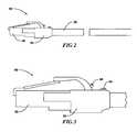
- FIG. 3is a diagrammatic front elevation view of the hood of the networking cable.
- FIG. 4is a diagrammatic cross section front elevation view of the hood of the networking cable.
- FIG. 5is an interior view of the some of the interior elements of the hood of the networking cable.
- FIG. 6is a diagrammatic bottom elevation view of the boot of the networking cable.
- FIG. 7is a view of the separator.
- FIG. 8is an exploded view of the end jack of the cable tracer system.
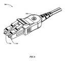
- FIG. 9is a view of a connector jack system for a fiber optic cable system.
- FIG. 1shown generally by the numeral 10 , illustrates, by way of background, a typical networked environment that includes servers, computers, hubs, peripheral devices, and a cable panel.
- a networkcould include, but is not limited to, other electronic devices such as workstations, switches, tape drives, storage devices, telephone switches, VOIP devices, and routers.
- the applicationanticipates any electronic device that can be part of a network. With large networks the total number of networking cables is large and routine maintenance functions as well as the addition or change of computers can lead to significant time and manpower requirements in tracing down connections throughout the system.
- FIG. 2shown generally by the numeral 50 , illustrates the networking cable that may be used in the networked environment of FIG. 1 .
- Cable 52as used in networking applications is typically composed of a plurality of insulated twisted conductor wire pairs encased in a flexible outer cover sheath. The number of twisted conductor wire pairs can vary depending on the application.
- Cat-6is a cable standard for Gigabit Ethernet and other network protocols that are backward compatible with the Category 5/5e and Category 3 cable standards. Compared with Cat-5 and Cat-5e, Cat-6 features more stringent specifications for crosstalk and system noise.
- the cable standardprovides performance of up to 250 MHz and is suitable for 10BASE-T, 100BASE-TX (Fast Ethernet), 1000BASE-T/1000BASE-TX (Gigabit Ethernet) and 10GBASE-T (10-Gigabit Ethernet).
- Category 6 cablehas a reduced maximum length when used for 10GBASE-T;
- Category 6a cable, or Augmented Category 6,is characterized to 500 MHz and has improved alien crosstalk characteristics, allowing 10GBASE-T to be run for the same distance as previous protocols.
- Category 6 cablecan be identified by the printing on the side of the cable sheath. Several other standards are in use and the use of any of them is anticipated.
- An additional conductor wire or wire pairis added so that a Cat-5 or Cat-6 cable can perform the tracing function described herein. The extra conductor wire will be referred to in this description as the indicator wire.
- the composite cablemay consist of coaxial, twin-axial, twisted, untwisted, shielded and unshielded pair wires, as is known in the art. Accordingly, the term “networking cable” is used in this description and in the appended claims will encompass all such variations of composite cable, including those that carry data and those that carry power.
- a connector assembly made up of a standard connector 56 coupled to a boot 54 on the end of the networking cableprovides for the connection of the cable to the various networked devices.
- a typical connector 56is an RJ-45, an eight wire connector commonly used in networking computers.
- a preferred embodimentis the use of a 10 conductor RJ-45.
- the use of a 10 conductor RJ-45allows the insertion of an additional cable pair from the main distribution frame (MDF) to the intermediate distribution frame (IDF), which enables a continuous continuity path that enables the use of the telltale light indicator on each end of the cable.
- MDFmain distribution frame
- IDFintermediate distribution frame
- the overall connector(connector plus boot) will be referred to as the connector hood in this description and in the appended claims.
- FIG. 3shown generally as the numeral 60 is a slightly enlarged illustration of the connector hood.
- an electrical telltale 64which can be used to produce an audio or visual signal for tracing network cables.
- a telltalecan be any electrically triggered device that emits a visual or audio signal that can be detected by a human.
- a preferred telltaleis a light emitting diode (LED), but could be other visual indicators such as a conventional light bulb, or a liquid crystal visual indicator.
- a button 68is shown, which can be manually pressed to engage a manual switch (not shown) which completes an indicator circuit that causes the telltale LED to flash repeatedly for a predetermined time.
- the indicator circuitincludes the indicator wire or wire pair that runs the complete length of the networking cable. It is important to note that the hood shown in FIG. 2 , which is shown on the “left” end of the networking cable has a identical twin hood on the “right” end that has identical circuitry as well as an LED and manual switch and is in electrical connection via the indicator wire or wire pair. The exact location of the button and telltale is not critical and they can be located on various surfaces of the connector hood.
- FIG. 4shown generally by the numeral 80 is another side view of an embodiment of a hood shown in cross section to demonstrate some of the internal components.
- Button 68is connected physically to a switch (to be shown) which when manually engaged completes an electrical circuit that powers electrical telltale 64 .
- button 68engages switch 72 that is mounted on printed circuit board 76 .
- Below printed circuit board 76is an integrated circuit 82 ( FIG. 4 ) that provides part of the intelligence of one of the embodiments and will be described further.
- printed circuit board 76is in electrical connection to a electric power source 90 via positive connection 86 and negative connection 88 .
- the wiring of a complete electrical circuit between electrical telltale 64 , switch 72 , integrated circuit 82 , and electric power source 90is done through the common printed circuit board 76 .
- FIG. 6shown generally by the numeral 100 , is a bottom view of boot 54 to show the embodiment in which the electric power source is a battery and in which door 92 can be moved to an open position to expose the battery port 94 where the battery ( 90 in FIG. 5 ) can be inserted.
- the electric power sourceis a battery and in which door 92 can be moved to an open position to expose the battery port 94 where the battery ( 90 in FIG. 5 ) can be inserted.
- a number of batteriescan be used in this application.
- a preferred batteryis a CR927 3-volt lithium battery.
- a number of similar batteriesare available from other manufacturers and the use of any of them is anticipated.
- powercould be supplied by other means than a battery.
- the power for the display capability of the networking cablecould supplied from Power Over Ethernet (POE), a technology for safely passing electrical power, along with data on Ethernet cabling.
- POEPower Over Ethernet
- other electric power sourcessuch as solar are possibilities.
- Another important aspectis the ability to have a useful and long-lived tracer circuit with only the on board electric power sources. This is especially important in the embodiment of an on board battery. Accordingly when the switch 72 is engaged by pushing button 68 ( FIGS. 4-5 ) it is desirable for the electrical telltales to signal for a prescribed amount of time but then shut off to conserve power. This can be accomplished in several ways. The simplest circuit would be one in which the circuit is engaged and drawing power from electric power source 90 once the first button 68 is pushed and is disengaged when one of the buttons 68 is pushed again. This embodiment is functional though it suffers from the weakness that users may accidentally push one of the buttons and leave the circuit engaged, draining the power from electric power source 90 .
- An improved embodimentis one in which pushing one of the buttons 68 engages power to the circuit for a prescribed amount of time and then disengages power to the circuit, conserving electric power source power.
- a number of simple electronic circuitscould perform that function. Fortunately very small and low cost integrated circuits designed to do exactly that as well as pulse the power are commercially available in large quantities.
- Integrated circuit board X1622available from Fulikai Electronic Technologies (China), is manufactured and sold to numerous toy manufacturers to provide a blinking light function to many toys. It is also used in the well-known shoes sold to children that have blinking LED lights that are activated when children press down on the shoes while walking. A number of similar integrated circuits are available from other manufacturers and the use of any of them is anticipated.
- a Radio Frequency Identification circuitreplaces the integrated circuit 82 .
- the use of an RFID tagexpands the uses of the proposed networking cable.
- the RFID tagcan be used for example to store information on the Media Access Control address (MAC address) of the device that one end of the network cable is attached to, or the jack number, port address, IP address, workstation identifier, or server identifier.
- the usercan then use an RFiD reader to quickly scan the other end of the networking cable and get a complete readout of the exact location of the cable connection without having to walk around looking for a flashing light on the other end.
- MAC addressMedia Access Control address
- the connector hoodwill accept a device that functions as a electric power source tester at either end of the cable.
- the integrated circuitincludes functionality that automatically indicates a condition of low electric power source power.
- FIG. 7illustrates such a separator. It is sized to fit completely within the jack at the end of the communications cable.
- the separator 150is molded from a non-conductive material and has channels 160 , 170 , 180 , and 190 for four twisted wire pairs coming from the communications cable. The separator maintains the twisted wire separation all through the connector jack. Channel 180 may carry in addition to one of the twisted wire pairs the indicator wire or wire pair that will carry the signal to the PCB board.
- the use of separator 150will allow the routine use of four twisted wire systems housed inside an over molded communications jack and in the presence of electronics inside the jack while maintaining the minimum crosstalk necessary to meet CAT6 reliability standards.
- the resulting networking cableis a completely self-contained tracing cable. It enables any technician or user to simply push one button to check for the location of the opposite end of a cable in a networked system. In the case of the second embodiment the telltale indication ceases after a prescribed amount of time, conserving electric power source power. But several other testing functionalities are possible and were discussed earlier.
- FIG. 9illustrates a connector jack system 300 designed for implementation in a fiber optic system.
- the fiber optic connectors 310are shown, as is button 320 .
- the enclosurecontains the other elements (electric power source, PCB board, etc) that operate the same way as in the non fiber optic embodiments described above.
Landscapes
- Physics & Mathematics (AREA)
- General Physics & Mathematics (AREA)
- Optics & Photonics (AREA)
- Engineering & Computer Science (AREA)
- Environmental & Geological Engineering (AREA)
- Computer Networks & Wireless Communication (AREA)
- Signal Processing (AREA)
- Insulated Conductors (AREA)
- Details Of Connecting Devices For Male And Female Coupling (AREA)
- Small-Scale Networks (AREA)
- Monitoring And Testing Of Transmission In General (AREA)
- Locating Faults (AREA)
Abstract
Description
Claims (7)
Priority Applications (1)
| Application Number | Priority Date | Filing Date | Title |
|---|---|---|---|
| US13/643,700US9196975B2 (en) | 2010-04-29 | 2011-04-27 | Networking cable tracer system |
Applications Claiming Priority (3)
| Application Number | Priority Date | Filing Date | Title |
|---|---|---|---|
| US34347110P | 2010-04-29 | 2010-04-29 | |
| PCT/US2011/000738WO2011139341A2 (en) | 2010-04-29 | 2011-04-27 | Networking cable tracer system |
| US13/643,700US9196975B2 (en) | 2010-04-29 | 2011-04-27 | Networking cable tracer system |
Related Parent Applications (1)
| Application Number | Title | Priority Date | Filing Date |
|---|---|---|---|
| PCT/US2011/000738A-371-Of-InternationalWO2011139341A2 (en) | 2010-04-29 | 2011-04-27 | Networking cable tracer system |
Related Child Applications (1)
| Application Number | Title | Priority Date | Filing Date |
|---|---|---|---|
| US14/868,966ContinuationUS9577904B2 (en) | 2010-04-29 | 2015-09-29 | Networking cable tracer system |
Publications (2)
| Publication Number | Publication Date |
|---|---|
| US20130039624A1 US20130039624A1 (en) | 2013-02-14 |
| US9196975B2true US9196975B2 (en) | 2015-11-24 |
Family
ID=44904277
Family Applications (4)
| Application Number | Title | Priority Date | Filing Date |
|---|---|---|---|
| US13/643,700Active2031-09-01US9196975B2 (en) | 2010-04-29 | 2011-04-27 | Networking cable tracer system |
| US14/868,966ActiveUS9577904B2 (en) | 2010-04-29 | 2015-09-29 | Networking cable tracer system |
| US15/437,323ActiveUS10178005B2 (en) | 2010-04-29 | 2017-02-20 | Networking cable tracer system |
| US16/209,311ActiveUS10785136B2 (en) | 2010-04-29 | 2018-12-04 | Networking cable tracer system |
Family Applications After (3)
| Application Number | Title | Priority Date | Filing Date |
|---|---|---|---|
| US14/868,966ActiveUS9577904B2 (en) | 2010-04-29 | 2015-09-29 | Networking cable tracer system |
| US15/437,323ActiveUS10178005B2 (en) | 2010-04-29 | 2017-02-20 | Networking cable tracer system |
| US16/209,311ActiveUS10785136B2 (en) | 2010-04-29 | 2018-12-04 | Networking cable tracer system |
Country Status (5)
| Country | Link |
|---|---|
| US (4) | US9196975B2 (en) |
| CN (2) | CN107508724B (en) |
| AU (1) | AU2011249011B2 (en) |
| CA (1) | CA2797629C (en) |
| WO (1) | WO2011139341A2 (en) |
Cited By (18)
| Publication number | Priority date | Publication date | Assignee | Title |
|---|---|---|---|---|
| US20160209604A1 (en)* | 2013-08-21 | 2016-07-21 | Christopher B. Scherer | Traceable networking cables with remote-released connectors |
| US9671551B2 (en) | 2012-02-13 | 2017-06-06 | Corning Optical Communications LLC | Visual tracer system for fiber optic cable |
| US20180013647A1 (en)* | 2010-04-29 | 2018-01-11 | Mertek Industries, Llc | Networking cable tracer system |
| US20180233863A1 (en)* | 2016-07-25 | 2018-08-16 | Checkall Inc. | Led lan cable connector capable of high speed data transmission, led lan cable capable of high speed data transmission, and led lan cable system capable of high speed data transmission |
| US10101545B2 (en)* | 2015-10-30 | 2018-10-16 | Corning Optical Communications LLC | Traceable cable assembly and connector |
| US10101553B2 (en) | 2015-05-20 | 2018-10-16 | Corning Optical Communications LLC | Traceable cable with side-emitting optical fiber and method of forming the same |
| US10107983B2 (en) | 2016-04-29 | 2018-10-23 | Corning Optical Communications LLC | Preferential mode coupling for enhanced traceable patch cord performance |
| US10185111B2 (en) | 2016-04-08 | 2019-01-22 | Corning Optical Communications LLC | Traceable end point cable assembly |
| US10222561B2 (en) | 2016-12-21 | 2019-03-05 | Corning Research & Development Corporation | Light launch device for transmitting light into a traceable fiber optic cable assembly with tracing optical fibers |
| US10228526B2 (en) | 2015-03-31 | 2019-03-12 | Corning Optical Communications LLC | Traceable cable with side-emitting optical fiber and method of forming the same |
| US10234614B2 (en) | 2017-01-20 | 2019-03-19 | Corning Research & Development Corporation | Light source assemblies and systems and methods with mode homogenization |
| US10338317B2 (en) | 2015-07-17 | 2019-07-02 | Corning Optical Communications LLC | Systems and methods for traceable cables |
| US10379309B2 (en) | 2014-11-18 | 2019-08-13 | Corning Optical Communications LLC | Traceable optical fiber cable and filtered viewing device for enhanced traceability |
| US10534135B2 (en) | 2015-07-17 | 2020-01-14 | Corning Optical Communications LLC | Systems and methods for tracing cables and cables for such systems and methods |
| US10539758B2 (en) | 2017-12-05 | 2020-01-21 | Corning Research & Development Corporation | Traceable fiber optic cable assembly with indication of polarity |
| US10539747B2 (en) | 2017-12-05 | 2020-01-21 | Corning Research & Development Corporation | Bend induced light scattering fiber and cable assemblies and method of making |
| US11689247B2 (en) | 2019-01-16 | 2023-06-27 | Mertek Industries, Llc | Patch cord including wireless components |
| US12300943B2 (en) | 2019-09-30 | 2025-05-13 | Mertek Industries, Llc | Patch panel traceable networking system |
Families Citing this family (181)
| Publication number | Priority date | Publication date | Assignee | Title |
|---|---|---|---|---|
| AU2012323998B2 (en) | 2011-10-28 | 2016-04-28 | Mertek Industries, Llc | Traceable cables |
| US20130115803A1 (en)* | 2011-11-09 | 2013-05-09 | Cisco Technology, Inc. | System and method for providing a visual indicator for cables |
| DE102012202225B4 (en)* | 2012-02-14 | 2015-10-22 | Te Connectivity Germany Gmbh | Plug housing with seal |
| US9113347B2 (en) | 2012-12-05 | 2015-08-18 | At&T Intellectual Property I, Lp | Backhaul link for distributed antenna system |
| US10009065B2 (en) | 2012-12-05 | 2018-06-26 | At&T Intellectual Property I, L.P. | Backhaul link for distributed antenna system |
| CA2898709C (en) | 2013-01-18 | 2021-02-16 | Christopher B. Scherer | Field-terminable traceable cables, components, kits, and methods |
| US9225127B2 (en)* | 2013-03-20 | 2015-12-29 | Lenovo (Singapore) Pte. Ltd. | Connection illumination using communication elements |
| US9999038B2 (en) | 2013-05-31 | 2018-06-12 | At&T Intellectual Property I, L.P. | Remote distributed antenna system |
| US9525524B2 (en) | 2013-05-31 | 2016-12-20 | At&T Intellectual Property I, L.P. | Remote distributed antenna system |
| CN103336338B (en)* | 2013-07-01 | 2016-03-23 | 深圳市特发信息光网科技股份有限公司 | A kind of method that optical cable tracker, optical cable and optical cable are followed the trail of |
| FR3012249A1 (en)* | 2013-10-22 | 2015-04-24 | Bull Sas | CABLE NETWORK COMPRISING A VISUAL REFERENCE DEVICE AND VISUAL TERMINAL SCREENING DEVICE FOR NETWORK CABLE. |
| US8897697B1 (en) | 2013-11-06 | 2014-11-25 | At&T Intellectual Property I, Lp | Millimeter-wave surface-wave communications |
| US9209902B2 (en) | 2013-12-10 | 2015-12-08 | At&T Intellectual Property I, L.P. | Quasi-optical coupler |
| US9500814B2 (en)* | 2014-03-26 | 2016-11-22 | Commscope Technologies Llc | Optical adapter module with managed connectivity |
| US10203465B2 (en)* | 2014-04-25 | 2019-02-12 | Commscope Technologies Llc | Managed connectivity in cable spool assemblies |
| US9973403B2 (en)* | 2014-05-09 | 2018-05-15 | Lawrence F. Glaser | Intelligent traces and connections in electronic systems |
| US9692101B2 (en) | 2014-08-26 | 2017-06-27 | At&T Intellectual Property I, L.P. | Guided wave couplers for coupling electromagnetic waves between a waveguide surface and a surface of a wire |
| US9768833B2 (en) | 2014-09-15 | 2017-09-19 | At&T Intellectual Property I, L.P. | Method and apparatus for sensing a condition in a transmission medium of electromagnetic waves |
| US10063280B2 (en) | 2014-09-17 | 2018-08-28 | At&T Intellectual Property I, L.P. | Monitoring and mitigating conditions in a communication network |
| US9500815B2 (en)* | 2014-09-25 | 2016-11-22 | Nexans | Fiber optic connector with power |
| US9628854B2 (en) | 2014-09-29 | 2017-04-18 | At&T Intellectual Property I, L.P. | Method and apparatus for distributing content in a communication network |
| US9615269B2 (en) | 2014-10-02 | 2017-04-04 | At&T Intellectual Property I, L.P. | Method and apparatus that provides fault tolerance in a communication network |
| US9685992B2 (en) | 2014-10-03 | 2017-06-20 | At&T Intellectual Property I, L.P. | Circuit panel network and methods thereof |
| US9503189B2 (en) | 2014-10-10 | 2016-11-22 | At&T Intellectual Property I, L.P. | Method and apparatus for arranging communication sessions in a communication system |
| US9973299B2 (en) | 2014-10-14 | 2018-05-15 | At&T Intellectual Property I, L.P. | Method and apparatus for adjusting a mode of communication in a communication network |
| US9762289B2 (en) | 2014-10-14 | 2017-09-12 | At&T Intellectual Property I, L.P. | Method and apparatus for transmitting or receiving signals in a transportation system |
| US9627768B2 (en) | 2014-10-21 | 2017-04-18 | At&T Intellectual Property I, L.P. | Guided-wave transmission device with non-fundamental mode propagation and methods for use therewith |
| US9577306B2 (en) | 2014-10-21 | 2017-02-21 | At&T Intellectual Property I, L.P. | Guided-wave transmission device and methods for use therewith |
| US9653770B2 (en) | 2014-10-21 | 2017-05-16 | At&T Intellectual Property I, L.P. | Guided wave coupler, coupling module and methods for use therewith |
| US9520945B2 (en) | 2014-10-21 | 2016-12-13 | At&T Intellectual Property I, L.P. | Apparatus for providing communication services and methods thereof |
| US9564947B2 (en) | 2014-10-21 | 2017-02-07 | At&T Intellectual Property I, L.P. | Guided-wave transmission device with diversity and methods for use therewith |
| US9769020B2 (en) | 2014-10-21 | 2017-09-19 | At&T Intellectual Property I, L.P. | Method and apparatus for responding to events affecting communications in a communication network |
| US9312919B1 (en) | 2014-10-21 | 2016-04-12 | At&T Intellectual Property I, Lp | Transmission device with impairment compensation and methods for use therewith |
| US9780834B2 (en) | 2014-10-21 | 2017-10-03 | At&T Intellectual Property I, L.P. | Method and apparatus for transmitting electromagnetic waves |
| US9997819B2 (en) | 2015-06-09 | 2018-06-12 | At&T Intellectual Property I, L.P. | Transmission medium and method for facilitating propagation of electromagnetic waves via a core |
| US9800327B2 (en) | 2014-11-20 | 2017-10-24 | At&T Intellectual Property I, L.P. | Apparatus for controlling operations of a communication device and methods thereof |
| US9461706B1 (en) | 2015-07-31 | 2016-10-04 | At&T Intellectual Property I, Lp | Method and apparatus for exchanging communication signals |
| US10243784B2 (en) | 2014-11-20 | 2019-03-26 | At&T Intellectual Property I, L.P. | System for generating topology information and methods thereof |
| US9742462B2 (en) | 2014-12-04 | 2017-08-22 | At&T Intellectual Property I, L.P. | Transmission medium and communication interfaces and methods for use therewith |
| US10009067B2 (en) | 2014-12-04 | 2018-06-26 | At&T Intellectual Property I, L.P. | Method and apparatus for configuring a communication interface |
| US9954287B2 (en) | 2014-11-20 | 2018-04-24 | At&T Intellectual Property I, L.P. | Apparatus for converting wireless signals and electromagnetic waves and methods thereof |
| US9654173B2 (en) | 2014-11-20 | 2017-05-16 | At&T Intellectual Property I, L.P. | Apparatus for powering a communication device and methods thereof |
| US10340573B2 (en) | 2016-10-26 | 2019-07-02 | At&T Intellectual Property I, L.P. | Launcher with cylindrical coupling device and methods for use therewith |
| US9680670B2 (en) | 2014-11-20 | 2017-06-13 | At&T Intellectual Property I, L.P. | Transmission device with channel equalization and control and methods for use therewith |
| US9544006B2 (en) | 2014-11-20 | 2017-01-10 | At&T Intellectual Property I, L.P. | Transmission device with mode division multiplexing and methods for use therewith |
| US10144036B2 (en) | 2015-01-30 | 2018-12-04 | At&T Intellectual Property I, L.P. | Method and apparatus for mitigating interference affecting a propagation of electromagnetic waves guided by a transmission medium |
| US9876570B2 (en) | 2015-02-20 | 2018-01-23 | At&T Intellectual Property I, Lp | Guided-wave transmission device with non-fundamental mode propagation and methods for use therewith |
| CN104656208B (en)* | 2015-03-17 | 2017-05-17 | 国家电网公司 | Device for seeking and checking fiber cores of short-distance optical fibers |
| US9749013B2 (en) | 2015-03-17 | 2017-08-29 | At&T Intellectual Property I, L.P. | Method and apparatus for reducing attenuation of electromagnetic waves guided by a transmission medium |
| US10224981B2 (en) | 2015-04-24 | 2019-03-05 | At&T Intellectual Property I, Lp | Passive electrical coupling device and methods for use therewith |
| US9705561B2 (en) | 2015-04-24 | 2017-07-11 | At&T Intellectual Property I, L.P. | Directional coupling device and methods for use therewith |
| US9948354B2 (en) | 2015-04-28 | 2018-04-17 | At&T Intellectual Property I, L.P. | Magnetic coupling device with reflective plate and methods for use therewith |
| US9793954B2 (en) | 2015-04-28 | 2017-10-17 | At&T Intellectual Property I, L.P. | Magnetic coupling device and methods for use therewith |
| US9490869B1 (en) | 2015-05-14 | 2016-11-08 | At&T Intellectual Property I, L.P. | Transmission medium having multiple cores and methods for use therewith |
| US9871282B2 (en) | 2015-05-14 | 2018-01-16 | At&T Intellectual Property I, L.P. | At least one transmission medium having a dielectric surface that is covered at least in part by a second dielectric |
| US9748626B2 (en) | 2015-05-14 | 2017-08-29 | At&T Intellectual Property I, L.P. | Plurality of cables having different cross-sectional shapes which are bundled together to form a transmission medium |
| US10714803B2 (en) | 2015-05-14 | 2020-07-14 | At&T Intellectual Property I, L.P. | Transmission medium and methods for use therewith |
| US10276907B2 (en) | 2015-05-14 | 2019-04-30 | At&T Intellectual Property I, L.P. | Transmission medium and methods for use therewith |
| US10679767B2 (en) | 2015-05-15 | 2020-06-09 | At&T Intellectual Property I, L.P. | Transmission medium having a conductive material and methods for use therewith |
| US10650940B2 (en) | 2015-05-15 | 2020-05-12 | At&T Intellectual Property I, L.P. | Transmission medium having a conductive material and methods for use therewith |
| US9917341B2 (en) | 2015-05-27 | 2018-03-13 | At&T Intellectual Property I, L.P. | Apparatus and method for launching electromagnetic waves and for modifying radial dimensions of the propagating electromagnetic waves |
| US9866309B2 (en) | 2015-06-03 | 2018-01-09 | At&T Intellectual Property I, Lp | Host node device and methods for use therewith |
| US10812174B2 (en) | 2015-06-03 | 2020-10-20 | At&T Intellectual Property I, L.P. | Client node device and methods for use therewith |
| US10348391B2 (en) | 2015-06-03 | 2019-07-09 | At&T Intellectual Property I, L.P. | Client node device with frequency conversion and methods for use therewith |
| US9912381B2 (en) | 2015-06-03 | 2018-03-06 | At&T Intellectual Property I, Lp | Network termination and methods for use therewith |
| US10103801B2 (en) | 2015-06-03 | 2018-10-16 | At&T Intellectual Property I, L.P. | Host node device and methods for use therewith |
| US10154493B2 (en) | 2015-06-03 | 2018-12-11 | At&T Intellectual Property I, L.P. | Network termination and methods for use therewith |
| US9913139B2 (en) | 2015-06-09 | 2018-03-06 | At&T Intellectual Property I, L.P. | Signal fingerprinting for authentication of communicating devices |
| US9608692B2 (en) | 2015-06-11 | 2017-03-28 | At&T Intellectual Property I, L.P. | Repeater and methods for use therewith |
| US10142086B2 (en) | 2015-06-11 | 2018-11-27 | At&T Intellectual Property I, L.P. | Repeater and methods for use therewith |
| US9820146B2 (en) | 2015-06-12 | 2017-11-14 | At&T Intellectual Property I, L.P. | Method and apparatus for authentication and identity management of communicating devices |
| US9667317B2 (en) | 2015-06-15 | 2017-05-30 | At&T Intellectual Property I, L.P. | Method and apparatus for providing security using network traffic adjustments |
| US9640850B2 (en) | 2015-06-25 | 2017-05-02 | At&T Intellectual Property I, L.P. | Methods and apparatus for inducing a non-fundamental wave mode on a transmission medium |
| US9865911B2 (en) | 2015-06-25 | 2018-01-09 | At&T Intellectual Property I, L.P. | Waveguide system for slot radiating first electromagnetic waves that are combined into a non-fundamental wave mode second electromagnetic wave on a transmission medium |
| US9509415B1 (en) | 2015-06-25 | 2016-11-29 | At&T Intellectual Property I, L.P. | Methods and apparatus for inducing a fundamental wave mode on a transmission medium |
| US9853342B2 (en) | 2015-07-14 | 2017-12-26 | At&T Intellectual Property I, L.P. | Dielectric transmission medium connector and methods for use therewith |
| US9722318B2 (en) | 2015-07-14 | 2017-08-01 | At&T Intellectual Property I, L.P. | Method and apparatus for coupling an antenna to a device |
| US9882257B2 (en) | 2015-07-14 | 2018-01-30 | At&T Intellectual Property I, L.P. | Method and apparatus for launching a wave mode that mitigates interference |
| US9836957B2 (en) | 2015-07-14 | 2017-12-05 | At&T Intellectual Property I, L.P. | Method and apparatus for communicating with premises equipment |
| US10148016B2 (en) | 2015-07-14 | 2018-12-04 | At&T Intellectual Property I, L.P. | Apparatus and methods for communicating utilizing an antenna array |
| US10341142B2 (en) | 2015-07-14 | 2019-07-02 | At&T Intellectual Property I, L.P. | Apparatus and methods for generating non-interfering electromagnetic waves on an uninsulated conductor |
| US9628116B2 (en) | 2015-07-14 | 2017-04-18 | At&T Intellectual Property I, L.P. | Apparatus and methods for transmitting wireless signals |
| US10044409B2 (en) | 2015-07-14 | 2018-08-07 | At&T Intellectual Property I, L.P. | Transmission medium and methods for use therewith |
| US10033107B2 (en) | 2015-07-14 | 2018-07-24 | At&T Intellectual Property I, L.P. | Method and apparatus for coupling an antenna to a device |
| US10320586B2 (en) | 2015-07-14 | 2019-06-11 | At&T Intellectual Property I, L.P. | Apparatus and methods for generating non-interfering electromagnetic waves on an insulated transmission medium |
| US9847566B2 (en) | 2015-07-14 | 2017-12-19 | At&T Intellectual Property I, L.P. | Method and apparatus for adjusting a field of a signal to mitigate interference |
| US10170840B2 (en) | 2015-07-14 | 2019-01-01 | At&T Intellectual Property I, L.P. | Apparatus and methods for sending or receiving electromagnetic signals |
| US10033108B2 (en) | 2015-07-14 | 2018-07-24 | At&T Intellectual Property I, L.P. | Apparatus and methods for generating an electromagnetic wave having a wave mode that mitigates interference |
| US10205655B2 (en) | 2015-07-14 | 2019-02-12 | At&T Intellectual Property I, L.P. | Apparatus and methods for communicating utilizing an antenna array and multiple communication paths |
| US10090606B2 (en) | 2015-07-15 | 2018-10-02 | At&T Intellectual Property I, L.P. | Antenna system with dielectric array and methods for use therewith |
| US9793951B2 (en) | 2015-07-15 | 2017-10-17 | At&T Intellectual Property I, L.P. | Method and apparatus for launching a wave mode that mitigates interference |
| US9608740B2 (en) | 2015-07-15 | 2017-03-28 | At&T Intellectual Property I, L.P. | Method and apparatus for launching a wave mode that mitigates interference |
| US9871283B2 (en) | 2015-07-23 | 2018-01-16 | At&T Intellectual Property I, Lp | Transmission medium having a dielectric core comprised of plural members connected by a ball and socket configuration |
| US10784670B2 (en) | 2015-07-23 | 2020-09-22 | At&T Intellectual Property I, L.P. | Antenna support for aligning an antenna |
| US9948333B2 (en) | 2015-07-23 | 2018-04-17 | At&T Intellectual Property I, L.P. | Method and apparatus for wireless communications to mitigate interference |
| US9912027B2 (en) | 2015-07-23 | 2018-03-06 | At&T Intellectual Property I, L.P. | Method and apparatus for exchanging communication signals |
| US9749053B2 (en) | 2015-07-23 | 2017-08-29 | At&T Intellectual Property I, L.P. | Node device, repeater and methods for use therewith |
| US9967173B2 (en) | 2015-07-31 | 2018-05-08 | At&T Intellectual Property I, L.P. | Method and apparatus for authentication and identity management of communicating devices |
| US9735833B2 (en) | 2015-07-31 | 2017-08-15 | At&T Intellectual Property I, L.P. | Method and apparatus for communications management in a neighborhood network |
| US10020587B2 (en) | 2015-07-31 | 2018-07-10 | At&T Intellectual Property I, L.P. | Radial antenna and methods for use therewith |
| US9904535B2 (en) | 2015-09-14 | 2018-02-27 | At&T Intellectual Property I, L.P. | Method and apparatus for distributing software |
| US9705571B2 (en) | 2015-09-16 | 2017-07-11 | At&T Intellectual Property I, L.P. | Method and apparatus for use with a radio distributed antenna system |
| US10136434B2 (en) | 2015-09-16 | 2018-11-20 | At&T Intellectual Property I, L.P. | Method and apparatus for use with a radio distributed antenna system having an ultra-wideband control channel |
| US10009063B2 (en) | 2015-09-16 | 2018-06-26 | At&T Intellectual Property I, L.P. | Method and apparatus for use with a radio distributed antenna system having an out-of-band reference signal |
| US10079661B2 (en) | 2015-09-16 | 2018-09-18 | At&T Intellectual Property I, L.P. | Method and apparatus for use with a radio distributed antenna system having a clock reference |
| US10051629B2 (en) | 2015-09-16 | 2018-08-14 | At&T Intellectual Property I, L.P. | Method and apparatus for use with a radio distributed antenna system having an in-band reference signal |
| US10009901B2 (en) | 2015-09-16 | 2018-06-26 | At&T Intellectual Property I, L.P. | Method, apparatus, and computer-readable storage medium for managing utilization of wireless resources between base stations |
| FR3041771B1 (en)* | 2015-09-24 | 2019-05-31 | Bull Sas | INTEGRATED SYSTEM FOR IDENTIFYING CABLES AND CONNECTED DEVICES |
| US9769128B2 (en) | 2015-09-28 | 2017-09-19 | At&T Intellectual Property I, L.P. | Method and apparatus for encryption of communications over a network |
| US9729197B2 (en) | 2015-10-01 | 2017-08-08 | At&T Intellectual Property I, L.P. | Method and apparatus for communicating network management traffic over a network |
| US9882277B2 (en) | 2015-10-02 | 2018-01-30 | At&T Intellectual Property I, Lp | Communication device and antenna assembly with actuated gimbal mount |
| US10074890B2 (en) | 2015-10-02 | 2018-09-11 | At&T Intellectual Property I, L.P. | Communication device and antenna with integrated light assembly |
| US9876264B2 (en) | 2015-10-02 | 2018-01-23 | At&T Intellectual Property I, Lp | Communication system, guided wave switch and methods for use therewith |
| US10665942B2 (en) | 2015-10-16 | 2020-05-26 | At&T Intellectual Property I, L.P. | Method and apparatus for adjusting wireless communications |
| US10355367B2 (en) | 2015-10-16 | 2019-07-16 | At&T Intellectual Property I, L.P. | Antenna structure for exchanging wireless signals |
| US10051483B2 (en) | 2015-10-16 | 2018-08-14 | At&T Intellectual Property I, L.P. | Method and apparatus for directing wireless signals |
| US10535961B2 (en)* | 2016-04-26 | 2020-01-14 | Ryan E. Cote | Electrical cables having integrated and manually controllable identification and illumination light sources |
| CN106154102A (en)* | 2016-07-29 | 2016-11-23 | 中航光电科技股份有限公司 | Cable identification module and composite cable assembly |
| US9912419B1 (en) | 2016-08-24 | 2018-03-06 | At&T Intellectual Property I, L.P. | Method and apparatus for managing a fault in a distributed antenna system |
| US9860075B1 (en) | 2016-08-26 | 2018-01-02 | At&T Intellectual Property I, L.P. | Method and communication node for broadband distribution |
| US10291311B2 (en) | 2016-09-09 | 2019-05-14 | At&T Intellectual Property I, L.P. | Method and apparatus for mitigating a fault in a distributed antenna system |
| SE541593C2 (en)* | 2016-09-15 | 2019-11-12 | Innspire Intelligent Hotels Ab | Cable for connecting an image displaying device to a digital computer network |
| US11032819B2 (en) | 2016-09-15 | 2021-06-08 | At&T Intellectual Property I, L.P. | Method and apparatus for use with a radio distributed antenna system having a control channel reference signal |
| US10135146B2 (en) | 2016-10-18 | 2018-11-20 | At&T Intellectual Property I, L.P. | Apparatus and methods for launching guided waves via circuits |
| US10135147B2 (en) | 2016-10-18 | 2018-11-20 | At&T Intellectual Property I, L.P. | Apparatus and methods for launching guided waves via an antenna |
| US10340600B2 (en) | 2016-10-18 | 2019-07-02 | At&T Intellectual Property I, L.P. | Apparatus and methods for launching guided waves via plural waveguide systems |
| US10374316B2 (en) | 2016-10-21 | 2019-08-06 | At&T Intellectual Property I, L.P. | System and dielectric antenna with non-uniform dielectric |
| US10811767B2 (en) | 2016-10-21 | 2020-10-20 | At&T Intellectual Property I, L.P. | System and dielectric antenna with convex dielectric radome |
| US9876605B1 (en) | 2016-10-21 | 2018-01-23 | At&T Intellectual Property I, L.P. | Launcher and coupling system to support desired guided wave mode |
| US9991580B2 (en) | 2016-10-21 | 2018-06-05 | At&T Intellectual Property I, L.P. | Launcher and coupling system for guided wave mode cancellation |
| US10312567B2 (en) | 2016-10-26 | 2019-06-04 | At&T Intellectual Property I, L.P. | Launcher with planar strip antenna and methods for use therewith |
| US10225025B2 (en) | 2016-11-03 | 2019-03-05 | At&T Intellectual Property I, L.P. | Method and apparatus for detecting a fault in a communication system |
| US10291334B2 (en) | 2016-11-03 | 2019-05-14 | At&T Intellectual Property I, L.P. | System for detecting a fault in a communication system |
| US10498044B2 (en) | 2016-11-03 | 2019-12-03 | At&T Intellectual Property I, L.P. | Apparatus for configuring a surface of an antenna |
| US10224634B2 (en) | 2016-11-03 | 2019-03-05 | At&T Intellectual Property I, L.P. | Methods and apparatus for adjusting an operational characteristic of an antenna |
| US10340603B2 (en) | 2016-11-23 | 2019-07-02 | At&T Intellectual Property I, L.P. | Antenna system having shielded structural configurations for assembly |
| US10178445B2 (en) | 2016-11-23 | 2019-01-08 | At&T Intellectual Property I, L.P. | Methods, devices, and systems for load balancing between a plurality of waveguides |
| US10340601B2 (en) | 2016-11-23 | 2019-07-02 | At&T Intellectual Property I, L.P. | Multi-antenna system and methods for use therewith |
| US10535928B2 (en) | 2016-11-23 | 2020-01-14 | At&T Intellectual Property I, L.P. | Antenna system and methods for use therewith |
| US10090594B2 (en) | 2016-11-23 | 2018-10-02 | At&T Intellectual Property I, L.P. | Antenna system having structural configurations for assembly |
| US10361489B2 (en) | 2016-12-01 | 2019-07-23 | At&T Intellectual Property I, L.P. | Dielectric dish antenna system and methods for use therewith |
| US10305190B2 (en) | 2016-12-01 | 2019-05-28 | At&T Intellectual Property I, L.P. | Reflecting dielectric antenna system and methods for use therewith |
| US10637149B2 (en) | 2016-12-06 | 2020-04-28 | At&T Intellectual Property I, L.P. | Injection molded dielectric antenna and methods for use therewith |
| US10135145B2 (en) | 2016-12-06 | 2018-11-20 | At&T Intellectual Property I, L.P. | Apparatus and methods for generating an electromagnetic wave along a transmission medium |
| US10819035B2 (en) | 2016-12-06 | 2020-10-27 | At&T Intellectual Property I, L.P. | Launcher with helical antenna and methods for use therewith |
| US10326494B2 (en) | 2016-12-06 | 2019-06-18 | At&T Intellectual Property I, L.P. | Apparatus for measurement de-embedding and methods for use therewith |
| US10382976B2 (en) | 2016-12-06 | 2019-08-13 | At&T Intellectual Property I, L.P. | Method and apparatus for managing wireless communications based on communication paths and network device positions |
| US10439675B2 (en) | 2016-12-06 | 2019-10-08 | At&T Intellectual Property I, L.P. | Method and apparatus for repeating guided wave communication signals |
| US9927517B1 (en) | 2016-12-06 | 2018-03-27 | At&T Intellectual Property I, L.P. | Apparatus and methods for sensing rainfall |
| US10755542B2 (en) | 2016-12-06 | 2020-08-25 | At&T Intellectual Property I, L.P. | Method and apparatus for surveillance via guided wave communication |
| US10020844B2 (en) | 2016-12-06 | 2018-07-10 | T&T Intellectual Property I, L.P. | Method and apparatus for broadcast communication via guided waves |
| US10727599B2 (en) | 2016-12-06 | 2020-07-28 | At&T Intellectual Property I, L.P. | Launcher with slot antenna and methods for use therewith |
| US10694379B2 (en) | 2016-12-06 | 2020-06-23 | At&T Intellectual Property I, L.P. | Waveguide system with device-based authentication and methods for use therewith |
| US9893795B1 (en) | 2016-12-07 | 2018-02-13 | At&T Intellectual Property I, Lp | Method and repeater for broadband distribution |
| US10446936B2 (en) | 2016-12-07 | 2019-10-15 | At&T Intellectual Property I, L.P. | Multi-feed dielectric antenna system and methods for use therewith |
| US10359749B2 (en) | 2016-12-07 | 2019-07-23 | At&T Intellectual Property I, L.P. | Method and apparatus for utilities management via guided wave communication |
| US10168695B2 (en) | 2016-12-07 | 2019-01-01 | At&T Intellectual Property I, L.P. | Method and apparatus for controlling an unmanned aircraft |
| US10389029B2 (en) | 2016-12-07 | 2019-08-20 | At&T Intellectual Property I, L.P. | Multi-feed dielectric antenna system with core selection and methods for use therewith |
| US10027397B2 (en) | 2016-12-07 | 2018-07-17 | At&T Intellectual Property I, L.P. | Distributed antenna system and methods for use therewith |
| US10139820B2 (en) | 2016-12-07 | 2018-11-27 | At&T Intellectual Property I, L.P. | Method and apparatus for deploying equipment of a communication system |
| US10547348B2 (en) | 2016-12-07 | 2020-01-28 | At&T Intellectual Property I, L.P. | Method and apparatus for switching transmission mediums in a communication system |
| US10243270B2 (en) | 2016-12-07 | 2019-03-26 | At&T Intellectual Property I, L.P. | Beam adaptive multi-feed dielectric antenna system and methods for use therewith |
| US10326689B2 (en) | 2016-12-08 | 2019-06-18 | At&T Intellectual Property I, L.P. | Method and system for providing alternative communication paths |
| US10601494B2 (en) | 2016-12-08 | 2020-03-24 | At&T Intellectual Property I, L.P. | Dual-band communication device and method for use therewith |
| US10916969B2 (en) | 2016-12-08 | 2021-02-09 | At&T Intellectual Property I, L.P. | Method and apparatus for providing power using an inductive coupling |
| US10389037B2 (en) | 2016-12-08 | 2019-08-20 | At&T Intellectual Property I, L.P. | Apparatus and methods for selecting sections of an antenna array and use therewith |
| US10777873B2 (en) | 2016-12-08 | 2020-09-15 | At&T Intellectual Property I, L.P. | Method and apparatus for mounting network devices |
| US10938108B2 (en) | 2016-12-08 | 2021-03-02 | At&T Intellectual Property I, L.P. | Frequency selective multi-feed dielectric antenna system and methods for use therewith |
| US10069535B2 (en) | 2016-12-08 | 2018-09-04 | At&T Intellectual Property I, L.P. | Apparatus and methods for launching electromagnetic waves having a certain electric field structure |
| US10530505B2 (en) | 2016-12-08 | 2020-01-07 | At&T Intellectual Property I, L.P. | Apparatus and methods for launching electromagnetic waves along a transmission medium |
| US10411356B2 (en) | 2016-12-08 | 2019-09-10 | At&T Intellectual Property I, L.P. | Apparatus and methods for selectively targeting communication devices with an antenna array |
| US9911020B1 (en) | 2016-12-08 | 2018-03-06 | At&T Intellectual Property I, L.P. | Method and apparatus for tracking via a radio frequency identification device |
| US10103422B2 (en) | 2016-12-08 | 2018-10-16 | At&T Intellectual Property I, L.P. | Method and apparatus for mounting network devices |
| US9998870B1 (en) | 2016-12-08 | 2018-06-12 | At&T Intellectual Property I, L.P. | Method and apparatus for proximity sensing |
| US10264586B2 (en) | 2016-12-09 | 2019-04-16 | At&T Mobility Ii Llc | Cloud-based packet controller and methods for use therewith |
| US9838896B1 (en) | 2016-12-09 | 2017-12-05 | At&T Intellectual Property I, L.P. | Method and apparatus for assessing network coverage |
| US10340983B2 (en) | 2016-12-09 | 2019-07-02 | At&T Intellectual Property I, L.P. | Method and apparatus for surveying remote sites via guided wave communications |
| US9973940B1 (en) | 2017-02-27 | 2018-05-15 | At&T Intellectual Property I, L.P. | Apparatus and methods for dynamic impedance matching of a guided wave launcher |
| US10298293B2 (en) | 2017-03-13 | 2019-05-21 | At&T Intellectual Property I, L.P. | Apparatus of communication utilizing wireless network devices |
| US20180269266A1 (en)* | 2017-03-16 | 2018-09-20 | Intel Corporation | Foveated displays for virtual and augmented reality |
| US10475298B1 (en) | 2018-07-10 | 2019-11-12 | International Business Machines Corporation | Assisting cable use by locating connector ends of the cable |
Citations (54)
| Publication number | Priority date | Publication date | Assignee | Title |
|---|---|---|---|---|
| US3960428A (en) | 1975-04-07 | 1976-06-01 | International Telephone And Telegraph Corporation | Electrical connector |
| US4761720A (en) | 1987-05-14 | 1988-08-02 | Wolo Manufacturing Corporation | Illuminated tape |
| US4837488A (en) | 1988-05-06 | 1989-06-06 | Ncr Corporation | Portable identifier and tester units for computer communication cables |
| US5159316A (en) | 1990-08-03 | 1992-10-27 | Lazzara Electronics, Inc. | Capacitance change article removal alarm |
| US5666453A (en)* | 1994-07-15 | 1997-09-09 | Roy Witte | Fiber optic jumper cables and tracing method using same |
| US5741152A (en) | 1995-04-25 | 1998-04-21 | Amphenol Corporation | Electrical connector with indicator lights |
| US5764043A (en) | 1996-12-20 | 1998-06-09 | Siecor Corporation | Traceable patch cord and connector assembly and method for locating patch cord ends |
| US5888100A (en)* | 1996-02-22 | 1999-03-30 | The Whitaker Corporation | Twisted pair cable and connector assembly |
| US6002331A (en)* | 1998-07-20 | 1999-12-14 | Laor; Herzel | Method and apparatus for identifying and tracking connections of communication lines |
| US6080007A (en)* | 1998-11-30 | 2000-06-27 | Hubbell Incorporated | Communication connector with wire holding sled |
| US6099345A (en)* | 1999-04-23 | 2000-08-08 | Hubbell Incorporated | Wire spacers for connecting cables to connectors |
| US6244908B1 (en) | 2000-08-04 | 2001-06-12 | Thomas & Betts International, Inc. | Switch within a data connector jack |
| US6280232B1 (en)* | 1998-03-31 | 2001-08-28 | Avaya Technology Corp. | Communication cable termination |
| US20020031955A1 (en) | 1999-01-15 | 2002-03-14 | Adc Telecommunications, Inc | Telecommunications jack assembly |
| US20020048990A1 (en)* | 2000-06-02 | 2002-04-25 | Marowsky Richard D. | Modular plug wire aligner |
| US6394853B1 (en) | 2000-08-04 | 2002-05-28 | Thomas & Betts International, Inc. | Data connector for selective switching between at least two distinct mating connector plugs |
| US6532328B1 (en) | 2000-10-31 | 2003-03-11 | International Business Machines Corporation | Network cable with optical identification element |
| US6558204B1 (en)* | 1999-02-19 | 2003-05-06 | Richard Weatherley | Plug assembly for data transmission and method of wiring same |
| US6577243B1 (en) | 1999-12-14 | 2003-06-10 | Alan J. Brown | Method and apparatus for tracing remote ends of networking cables |
| US20030157842A1 (en)* | 2002-02-15 | 2003-08-21 | Arnett Jaime R. | Terminal housing for a communication jack assembly |
| US20030199192A1 (en)* | 2002-04-22 | 2003-10-23 | Panduit Corporation | Modular cable termination plug |
| US20040038564A1 (en) | 2002-06-21 | 2004-02-26 | Bi-Jian Yan | Electrical connector |
| US20040160774A1 (en) | 2003-02-13 | 2004-08-19 | Dell Products L.P. | Cable having an illuminating tracer element mounted thereon |
| US6790096B2 (en) | 2001-12-28 | 2004-09-14 | Hon Hai Precision Ind. Co., Ltd. | Cable assembly having arrangement for organizing cable |
| US6798183B2 (en) | 2002-06-04 | 2004-09-28 | Fluke Corporation | Method of and apparatus for simultaneously providing tone and intermittent link onto a cable to assist identifying the cable |
| US20050224585A1 (en)* | 2004-04-02 | 2005-10-13 | Durrant Richard C E | Radio frequency identification of a connector by a patch panel or other similar structure |
| US7049937B1 (en) | 2002-06-11 | 2006-05-23 | Nortel Networks Limited | Self-identifying cable for interconnecting electronic devices |
| US7081808B2 (en)* | 2002-09-13 | 2006-07-25 | Fitel Usa Corp. | Self-registration systems and methods for dynamically updating information related to a network |
| US20060162947A1 (en)* | 2005-01-19 | 2006-07-27 | Masud Bolouri-Saransar | Communication channels with suppression cores |
| US20060232385A1 (en)* | 2005-04-13 | 2006-10-19 | Scherer Christopher B | Networking cable tracer system |
| US20070116411A1 (en)* | 2005-11-18 | 2007-05-24 | Mark Benton | Transceiver/fiber optic connector adaptor with patch cord id reading capability |
| US20070190863A1 (en)* | 2006-02-13 | 2007-08-16 | Panduit Corp. | Connector with crosstalk compensation |
| US7335066B2 (en)* | 2005-12-16 | 2008-02-26 | James A. Carroll | Network connector and connection system |
| US20080122579A1 (en)* | 2006-11-29 | 2008-05-29 | Commscope Solutions Properties, Llc | Telecommunications patching system that facilitates detection and identification of patch cords |
| US7547150B2 (en)* | 2007-03-09 | 2009-06-16 | Corning Cable Systems, Llc | Optically addressed RFID elements |
| US20100079248A1 (en)* | 2008-09-29 | 2010-04-01 | Johannes Ian Greveling | Optical fiber connector assembly with wire-based RFID antenna |
| US20100098425A1 (en)* | 2008-05-02 | 2010-04-22 | Telescent Inc. | Radio frequency identification overlay network for fiber optic communication systems |
| US7760094B1 (en)* | 2006-12-14 | 2010-07-20 | Corning Cable Systems Llc | RFID systems and methods for optical fiber network deployment and maintenance |
| US7772975B2 (en)* | 2006-10-31 | 2010-08-10 | Corning Cable Systems, Llc | System for mapping connections using RFID function |
| US7782202B2 (en)* | 2006-10-31 | 2010-08-24 | Corning Cable Systems, Llc | Radio frequency identification of component connections |
| US20110043333A1 (en)* | 2009-08-21 | 2011-02-24 | Michael German | Systems for Automatically Tracking Patching Connections to Network Devices Using a Separate Control Channel and Related Patching Equipment and Methods |
| US7910834B2 (en)* | 2008-05-27 | 2011-03-22 | Voltstar Technologies, Inc. | Energy saving cable assemblies |
| US7910833B2 (en)* | 2008-05-27 | 2011-03-22 | Voltstar Technologies, Inc. | Energy-saving power adapter/charger |
| US7920764B2 (en)* | 2007-05-04 | 2011-04-05 | Anthony Stephen Kewitsch | Electrically traceable and identifiable fiber optic cables and connectors |
| US7940182B2 (en)* | 2008-04-30 | 2011-05-10 | Alcatel Lucent | RFID encoding for identifying system interconnect cables |
| US20110116748A1 (en)* | 2009-10-16 | 2011-05-19 | Adc Telecommunications, Inc. | Managed connectivity in fiber optic systems and methods thereof |
| US7960648B2 (en)* | 2008-05-27 | 2011-06-14 | Voltstar Technologies, Inc. | Energy saving cable assemblies |
| US7965186B2 (en)* | 2007-03-09 | 2011-06-21 | Corning Cable Systems, Llc | Passive RFID elements having visual indicators |
| US7972183B1 (en)* | 2010-03-19 | 2011-07-05 | Commscope, Inc. Of North Carolina | Sled that reduces the next variations between modular plugs |
| US8210755B2 (en)* | 2006-12-29 | 2012-07-03 | Alcatel Lucent | Identifiable fiber optics |
| US8264355B2 (en)* | 2006-12-14 | 2012-09-11 | Corning Cable Systems Llc | RFID systems and methods for optical fiber network deployment and maintenance |
| US20130039624A1 (en)* | 2010-04-29 | 2013-02-14 | Christopher Briand Scherer | Networking Cable Tracer System |
| US8606972B2 (en)* | 2011-11-30 | 2013-12-10 | International Business Machines Corporation | Cable identification using data traffic activity information |
| US8611234B1 (en)* | 2011-07-11 | 2013-12-17 | Lockheed Martin Corporation | Network interface with cable tracing |
Family Cites Families (23)
| Publication number | Priority date | Publication date | Assignee | Title |
|---|---|---|---|---|
| IL129883A0 (en)* | 1999-05-10 | 2000-02-29 | Rit Techn Ltd | Cable organizer |
| US7327278B2 (en)* | 1999-12-14 | 2008-02-05 | Alan J. Brown | Method and apparatus for tracing remote ends of networking cables |
| CN1246933C (en)* | 2000-06-26 | 2006-03-22 | 瑞特技术有限公司 | Cable combiner |
| US6456768B1 (en)* | 2000-10-18 | 2002-09-24 | Fitel Usa Corp. | Optical fiber cable tracing system |
| US6568953B1 (en)* | 2002-01-31 | 2003-05-27 | Hubbell Incorporated | Electrical connector with overtwisted wire pairs |
| US6808116B1 (en)* | 2002-05-29 | 2004-10-26 | At&T Corp. | Fiber jumpers with data storage method and apparatus |
| TW566719U (en)* | 2002-05-30 | 2003-12-11 | Yuan-Huei Peng | Network plug structure |
| US20040052471A1 (en)* | 2002-09-13 | 2004-03-18 | Fitel Usa Corp. | Connector systems for dynamically updating information related to a network and methods for developing the connector systems |
| US7021808B2 (en)* | 2002-10-08 | 2006-04-04 | Currie Robert M | Illuminated rope |
| US7662005B2 (en) | 2003-03-14 | 2010-02-16 | Brian Provost | Outboard motor with reverse shift |
| US7513787B2 (en)* | 2004-01-09 | 2009-04-07 | Hubbell Incorporated | Dielectric insert assembly for a communication connector to optimize crosstalk |
| US7165728B2 (en)* | 2004-04-02 | 2007-01-23 | Stratos International, Inc. | Radio frequency identification for transfer of component information in fiber optic testing |
| CN1738108A (en)* | 2004-08-20 | 2006-02-22 | 美国智慧公司 | Device with light source plug pin |
| US7336883B2 (en)* | 2005-09-08 | 2008-02-26 | Stratos International, Inc. | Indexing optical fiber adapter |
| US20070197094A1 (en)* | 2006-02-08 | 2007-08-23 | The Siemon Company | Contacts For Use In Monitoring Connection Patterns In Data Ports |
| GB2448937B (en)* | 2007-05-04 | 2009-10-14 | Brand Rex Ltd | Improvements in and relating to electrical connectors |
| WO2009048899A1 (en)* | 2007-10-08 | 2009-04-16 | The Siemon Company | Contacts for use in monitoring connection patterns in data ports |
| US7670170B2 (en)* | 2008-04-30 | 2010-03-02 | Tyco Electronics Corporation | Connector assembly having a light pipe assembly |
| US7572071B1 (en)* | 2008-08-01 | 2009-08-11 | Hon Hai Precision Ind. Co., Ltd. | Cable assembly utilized for different kinds of signal transmission |
| EP3301767B1 (en)* | 2008-12-31 | 2020-11-04 | Panduit Corp | Patch cord with insertion detection and light illumination capabilities |
| AU2012323998B2 (en)* | 2011-10-28 | 2016-04-28 | Mertek Industries, Llc | Traceable cables |
| US8620123B2 (en)* | 2012-02-13 | 2013-12-31 | Corning Cable Systems Llc | Visual tracer system for fiber optic cable |
| TWI628672B (en)* | 2013-08-21 | 2018-07-01 | 克里斯多福B 雪羅 | Networking cables for transmitting data and method of assembling a connector for a networking cable |
- 2011
- 2011-04-27CACA2797629Apatent/CA2797629C/enactiveActive
- 2011-04-27WOPCT/US2011/000738patent/WO2011139341A2/enactiveApplication Filing
- 2011-04-27CNCN201710703590.8Apatent/CN107508724B/enactiveActive
- 2011-04-27CNCN201180020436.1Apatent/CN102859807B/enactiveActive
- 2011-04-27USUS13/643,700patent/US9196975B2/enactiveActive
- 2011-04-27AUAU2011249011Apatent/AU2011249011B2/enactiveActive
- 2015
- 2015-09-29USUS14/868,966patent/US9577904B2/enactiveActive
- 2017
- 2017-02-20USUS15/437,323patent/US10178005B2/enactiveActive
- 2018
- 2018-12-04USUS16/209,311patent/US10785136B2/enactiveActive
Patent Citations (73)
| Publication number | Priority date | Publication date | Assignee | Title |
|---|---|---|---|---|
| US3960428A (en) | 1975-04-07 | 1976-06-01 | International Telephone And Telegraph Corporation | Electrical connector |
| US4761720A (en) | 1987-05-14 | 1988-08-02 | Wolo Manufacturing Corporation | Illuminated tape |
| US4837488A (en) | 1988-05-06 | 1989-06-06 | Ncr Corporation | Portable identifier and tester units for computer communication cables |
| US5159316A (en) | 1990-08-03 | 1992-10-27 | Lazzara Electronics, Inc. | Capacitance change article removal alarm |
| US5666453A (en)* | 1994-07-15 | 1997-09-09 | Roy Witte | Fiber optic jumper cables and tracing method using same |
| US5741152A (en) | 1995-04-25 | 1998-04-21 | Amphenol Corporation | Electrical connector with indicator lights |
| US5888100A (en)* | 1996-02-22 | 1999-03-30 | The Whitaker Corporation | Twisted pair cable and connector assembly |
| US5764043A (en) | 1996-12-20 | 1998-06-09 | Siecor Corporation | Traceable patch cord and connector assembly and method for locating patch cord ends |
| US6280232B1 (en)* | 1998-03-31 | 2001-08-28 | Avaya Technology Corp. | Communication cable termination |
| US6002331A (en)* | 1998-07-20 | 1999-12-14 | Laor; Herzel | Method and apparatus for identifying and tracking connections of communication lines |
| US6080007A (en)* | 1998-11-30 | 2000-06-27 | Hubbell Incorporated | Communication connector with wire holding sled |
| US20020031955A1 (en) | 1999-01-15 | 2002-03-14 | Adc Telecommunications, Inc | Telecommunications jack assembly |
| US6558204B1 (en)* | 1999-02-19 | 2003-05-06 | Richard Weatherley | Plug assembly for data transmission and method of wiring same |
| US6099345A (en)* | 1999-04-23 | 2000-08-08 | Hubbell Incorporated | Wire spacers for connecting cables to connectors |
| US6577243B1 (en) | 1999-12-14 | 2003-06-10 | Alan J. Brown | Method and apparatus for tracing remote ends of networking cables |
| US6975242B2 (en) | 1999-12-14 | 2005-12-13 | Alan J. Brown | Method and apparatus for tracking remote ends of networking cables |
| US20030222786A1 (en) | 1999-12-14 | 2003-12-04 | John Dannenmann | Method and apparatus for tracking remote ends of networking cables |
| US20020048990A1 (en)* | 2000-06-02 | 2002-04-25 | Marowsky Richard D. | Modular plug wire aligner |
| US6524128B2 (en)* | 2000-06-02 | 2003-02-25 | Stewart Connector Systems, Inc. | Modular plug wire aligner |
| US6394853B1 (en) | 2000-08-04 | 2002-05-28 | Thomas & Betts International, Inc. | Data connector for selective switching between at least two distinct mating connector plugs |
| US6244908B1 (en) | 2000-08-04 | 2001-06-12 | Thomas & Betts International, Inc. | Switch within a data connector jack |
| US6532328B1 (en) | 2000-10-31 | 2003-03-11 | International Business Machines Corporation | Network cable with optical identification element |
| US6790096B2 (en) | 2001-12-28 | 2004-09-14 | Hon Hai Precision Ind. Co., Ltd. | Cable assembly having arrangement for organizing cable |
| US20030157842A1 (en)* | 2002-02-15 | 2003-08-21 | Arnett Jaime R. | Terminal housing for a communication jack assembly |
| US20070105453A1 (en)* | 2002-04-22 | 2007-05-10 | Panduit Corp. | Modular cable termination plug |
| US20120058689A1 (en)* | 2002-04-22 | 2012-03-08 | Panduit Corp. | Modular Cable Termination Plug |
| US20080220658A1 (en)* | 2002-04-22 | 2008-09-11 | Panduit Corp. | Modular cable termination plug |
| US6811445B2 (en)* | 2002-04-22 | 2004-11-02 | Panduit Corp. | Modular cable termination plug |
| US20050037672A1 (en)* | 2002-04-22 | 2005-02-17 | Panduit Corporation | Modular cable termination plug |
| US8043124B2 (en)* | 2002-04-22 | 2011-10-25 | Panduit Corp. | Modular cable termination plug |
| US8702453B2 (en)* | 2002-04-22 | 2014-04-22 | Panduit Corp. | Modular cable termination plug |
| US7556536B2 (en)* | 2002-04-22 | 2009-07-07 | Panduit Corp. | Modular cable termination plug |
| US20060134996A1 (en)* | 2002-04-22 | 2006-06-22 | Panduit Corporation | Modular cable termination plug |
| US7374458B2 (en)* | 2002-04-22 | 2008-05-20 | Panduit Corp. | Modular cable termination plug |
| US8277260B2 (en)* | 2002-04-22 | 2012-10-02 | Panduit Corp. | Modular cable termination plug |
| US20130052860A1 (en)* | 2002-04-22 | 2013-02-28 | Panduit Corp. | Modular Cable Termination Plug |
| US7168994B2 (en)* | 2002-04-22 | 2007-01-30 | Panduit Corp. | Modular cable termination plug |
| US20030199192A1 (en)* | 2002-04-22 | 2003-10-23 | Panduit Corporation | Modular cable termination plug |
| US20090269973A1 (en)* | 2002-04-22 | 2009-10-29 | Panduit Corp. | Modular cable termination plug |
| US6798183B2 (en) | 2002-06-04 | 2004-09-28 | Fluke Corporation | Method of and apparatus for simultaneously providing tone and intermittent link onto a cable to assist identifying the cable |
| US7049937B1 (en) | 2002-06-11 | 2006-05-23 | Nortel Networks Limited | Self-identifying cable for interconnecting electronic devices |
| US20040038564A1 (en) | 2002-06-21 | 2004-02-26 | Bi-Jian Yan | Electrical connector |
| US7081808B2 (en)* | 2002-09-13 | 2006-07-25 | Fitel Usa Corp. | Self-registration systems and methods for dynamically updating information related to a network |
| US20040160774A1 (en) | 2003-02-13 | 2004-08-19 | Dell Products L.P. | Cable having an illuminating tracer element mounted thereon |
| US20050224585A1 (en)* | 2004-04-02 | 2005-10-13 | Durrant Richard C E | Radio frequency identification of a connector by a patch panel or other similar structure |
| US20060162947A1 (en)* | 2005-01-19 | 2006-07-27 | Masud Bolouri-Saransar | Communication channels with suppression cores |
| US7221284B2 (en) | 2005-04-13 | 2007-05-22 | Mertek Industries, Llc | Networking cable tracer system |
| US20060232385A1 (en)* | 2005-04-13 | 2006-10-19 | Scherer Christopher B | Networking cable tracer system |
| US7226217B1 (en)* | 2005-11-18 | 2007-06-05 | Stratos International, Inc. | Transceiver/fiber optic connector adaptor with patch cord ID reading capability |
| US20070116411A1 (en)* | 2005-11-18 | 2007-05-24 | Mark Benton | Transceiver/fiber optic connector adaptor with patch cord id reading capability |
| US7335066B2 (en)* | 2005-12-16 | 2008-02-26 | James A. Carroll | Network connector and connection system |
| US20070190863A1 (en)* | 2006-02-13 | 2007-08-16 | Panduit Corp. | Connector with crosstalk compensation |
| US7772975B2 (en)* | 2006-10-31 | 2010-08-10 | Corning Cable Systems, Llc | System for mapping connections using RFID function |
| US7782202B2 (en)* | 2006-10-31 | 2010-08-24 | Corning Cable Systems, Llc | Radio frequency identification of component connections |
| US20080122579A1 (en)* | 2006-11-29 | 2008-05-29 | Commscope Solutions Properties, Llc | Telecommunications patching system that facilitates detection and identification of patch cords |
| US7760094B1 (en)* | 2006-12-14 | 2010-07-20 | Corning Cable Systems Llc | RFID systems and methods for optical fiber network deployment and maintenance |
| US8264355B2 (en)* | 2006-12-14 | 2012-09-11 | Corning Cable Systems Llc | RFID systems and methods for optical fiber network deployment and maintenance |
| US8210755B2 (en)* | 2006-12-29 | 2012-07-03 | Alcatel Lucent | Identifiable fiber optics |
| US7965186B2 (en)* | 2007-03-09 | 2011-06-21 | Corning Cable Systems, Llc | Passive RFID elements having visual indicators |
| US7547150B2 (en)* | 2007-03-09 | 2009-06-16 | Corning Cable Systems, Llc | Optically addressed RFID elements |
| US7920764B2 (en)* | 2007-05-04 | 2011-04-05 | Anthony Stephen Kewitsch | Electrically traceable and identifiable fiber optic cables and connectors |
| US7940182B2 (en)* | 2008-04-30 | 2011-05-10 | Alcatel Lucent | RFID encoding for identifying system interconnect cables |
| US20100098425A1 (en)* | 2008-05-02 | 2010-04-22 | Telescent Inc. | Radio frequency identification overlay network for fiber optic communication systems |
| US7960648B2 (en)* | 2008-05-27 | 2011-06-14 | Voltstar Technologies, Inc. | Energy saving cable assemblies |
| US7910833B2 (en)* | 2008-05-27 | 2011-03-22 | Voltstar Technologies, Inc. | Energy-saving power adapter/charger |
| US7910834B2 (en)* | 2008-05-27 | 2011-03-22 | Voltstar Technologies, Inc. | Energy saving cable assemblies |
| US20100079248A1 (en)* | 2008-09-29 | 2010-04-01 | Johannes Ian Greveling | Optical fiber connector assembly with wire-based RFID antenna |
| US20110043333A1 (en)* | 2009-08-21 | 2011-02-24 | Michael German | Systems for Automatically Tracking Patching Connections to Network Devices Using a Separate Control Channel and Related Patching Equipment and Methods |
| US20110116748A1 (en)* | 2009-10-16 | 2011-05-19 | Adc Telecommunications, Inc. | Managed connectivity in fiber optic systems and methods thereof |
| US7972183B1 (en)* | 2010-03-19 | 2011-07-05 | Commscope, Inc. Of North Carolina | Sled that reduces the next variations between modular plugs |
| US20130039624A1 (en)* | 2010-04-29 | 2013-02-14 | Christopher Briand Scherer | Networking Cable Tracer System |
| US8611234B1 (en)* | 2011-07-11 | 2013-12-17 | Lockheed Martin Corporation | Network interface with cable tracing |
| US8606972B2 (en)* | 2011-11-30 | 2013-12-10 | International Business Machines Corporation | Cable identification using data traffic activity information |
Cited By (27)
| Publication number | Priority date | Publication date | Assignee | Title |
|---|---|---|---|---|
| US10178005B2 (en)* | 2010-04-29 | 2019-01-08 | Mertek Industries, Llc | Networking cable tracer system |
| US20190349276A1 (en)* | 2010-04-29 | 2019-11-14 | Mertek Industries, Llc | Networking cable tracer system |
| US10785136B2 (en)* | 2010-04-29 | 2020-09-22 | Mertek Industries, Llc | Networking cable tracer system |
| US20180013647A1 (en)* | 2010-04-29 | 2018-01-11 | Mertek Industries, Llc | Networking cable tracer system |
| US9671551B2 (en) | 2012-02-13 | 2017-06-06 | Corning Optical Communications LLC | Visual tracer system for fiber optic cable |
| US9810859B2 (en)* | 2013-08-21 | 2017-11-07 | Mertek Industries, Llc | Traceable networking cables with remote-released connectors |
| US10732364B2 (en) | 2013-08-21 | 2020-08-04 | Mertek Industries, Llc | Traceable networking cables with remote-released connectors |
| US20160209604A1 (en)* | 2013-08-21 | 2016-07-21 | Christopher B. Scherer | Traceable networking cables with remote-released connectors |
| US10215935B2 (en)* | 2013-08-21 | 2019-02-26 | Mertek Industries, Llc | Traceable networking cables with remote-released connectors |
| US10379309B2 (en) | 2014-11-18 | 2019-08-13 | Corning Optical Communications LLC | Traceable optical fiber cable and filtered viewing device for enhanced traceability |
| US10228526B2 (en) | 2015-03-31 | 2019-03-12 | Corning Optical Communications LLC | Traceable cable with side-emitting optical fiber and method of forming the same |
| US10101553B2 (en) | 2015-05-20 | 2018-10-16 | Corning Optical Communications LLC | Traceable cable with side-emitting optical fiber and method of forming the same |
| US10534135B2 (en) | 2015-07-17 | 2020-01-14 | Corning Optical Communications LLC | Systems and methods for tracing cables and cables for such systems and methods |
| US10338317B2 (en) | 2015-07-17 | 2019-07-02 | Corning Optical Communications LLC | Systems and methods for traceable cables |
| US10101545B2 (en)* | 2015-10-30 | 2018-10-16 | Corning Optical Communications LLC | Traceable cable assembly and connector |
| US10185111B2 (en) | 2016-04-08 | 2019-01-22 | Corning Optical Communications LLC | Traceable end point cable assembly |
| US10107983B2 (en) | 2016-04-29 | 2018-10-23 | Corning Optical Communications LLC | Preferential mode coupling for enhanced traceable patch cord performance |
| US10063019B1 (en)* | 2016-07-25 | 2018-08-28 | Checkall Inc. | LED LAN cable connector capable of high speed data transmission, LED LAN cable capable of high speed data transmission, and LED LAN cable system capable of high speed data transmission |
| US20180233863A1 (en)* | 2016-07-25 | 2018-08-16 | Checkall Inc. | Led lan cable connector capable of high speed data transmission, led lan cable capable of high speed data transmission, and led lan cable system capable of high speed data transmission |
| US10222560B2 (en) | 2016-12-21 | 2019-03-05 | Corning Research & Development Corporation | Traceable fiber optic cable assembly with fiber guide and tracing optical fibers for carrying light received from a light launch device |
| US10222561B2 (en) | 2016-12-21 | 2019-03-05 | Corning Research & Development Corporation | Light launch device for transmitting light into a traceable fiber optic cable assembly with tracing optical fibers |
| US10545298B2 (en) | 2016-12-21 | 2020-01-28 | Corning Research & Development Corporation | Traceable fiber optic cable assembly with illumination structure and tracing optical fibers for carrying light received from a light launch device |
| US10234614B2 (en) | 2017-01-20 | 2019-03-19 | Corning Research & Development Corporation | Light source assemblies and systems and methods with mode homogenization |
| US10539758B2 (en) | 2017-12-05 | 2020-01-21 | Corning Research & Development Corporation | Traceable fiber optic cable assembly with indication of polarity |
| US10539747B2 (en) | 2017-12-05 | 2020-01-21 | Corning Research & Development Corporation | Bend induced light scattering fiber and cable assemblies and method of making |
| US11689247B2 (en) | 2019-01-16 | 2023-06-27 | Mertek Industries, Llc | Patch cord including wireless components |
| US12300943B2 (en) | 2019-09-30 | 2025-05-13 | Mertek Industries, Llc | Patch panel traceable networking system |
Also Published As
| Publication number | Publication date |
|---|---|
| CA2797629A1 (en) | 2011-11-10 |
| CN107508724B (en) | 2022-03-08 |
| CN102859807B (en) | 2017-09-12 |
| WO2011139341A2 (en) | 2011-11-10 |
| CA2797629C (en) | 2017-02-28 |
| US20190349276A1 (en) | 2019-11-14 |
| CN107508724A (en) | 2017-12-22 |
| US20180013647A1 (en) | 2018-01-11 |
| US20130039624A1 (en) | 2013-02-14 |
| US10785136B2 (en) | 2020-09-22 |
| WO2011139341A3 (en) | 2012-01-12 |
| AU2011249011B2 (en) | 2014-07-03 |
| US10178005B2 (en) | 2019-01-08 |
| AU2011249011A1 (en) | 2012-11-08 |
| CN102859807A (en) | 2013-01-02 |
| US9577904B2 (en) | 2017-02-21 |
| US20160020975A1 (en) | 2016-01-21 |
Similar Documents
| Publication | Publication Date | Title |
|---|---|---|
| US10785136B2 (en) | Networking cable tracer system | |
| US7221284B2 (en) | Networking cable tracer system | |
| US10732364B2 (en) | Traceable networking cables with remote-released connectors | |
| US10481183B2 (en) | Traceable cables | |
| CN105051989B (en) | Field-terminable traceable cable, component, kit and method | |
| US7327278B2 (en) | Method and apparatus for tracing remote ends of networking cables | |
| US6577243B1 (en) | Method and apparatus for tracing remote ends of networking cables | |
| CA2433562C (en) | Method and apparatus for tracing remote ends of networking cables |
Legal Events
| Date | Code | Title | Description |
|---|---|---|---|
| AS | Assignment | Owner name:MERTEK INDUSTRIES, LLC, TEXAS Free format text:ASSIGNMENT OF ASSIGNORS INTEREST;ASSIGNORS:SCHERER, CHRISTOPHER BRIAND;SHOLTIS, JONATHAN KEITH;REEL/FRAME:031931/0821 Effective date:20140106 | |
| STCF | Information on status: patent grant | Free format text:PATENTED CASE | |
| FEPP | Fee payment procedure | Free format text:ENTITY STATUS SET TO UNDISCOUNTED (ORIGINAL EVENT CODE: BIG.); ENTITY STATUS OF PATENT OWNER: LARGE ENTITY | |
| MAFP | Maintenance fee payment | Free format text:PAYMENT OF MAINTENANCE FEE, 4TH YEAR, LARGE ENTITY (ORIGINAL EVENT CODE: M1551); ENTITY STATUS OF PATENT OWNER: LARGE ENTITY Year of fee payment:4 | |
| FEPP | Fee payment procedure | Free format text:PETITION RELATED TO MAINTENANCE FEES GRANTED (ORIGINAL EVENT CODE: PTGR); ENTITY STATUS OF PATENT OWNER: LARGE ENTITY | |
| MAFP | Maintenance fee payment | Free format text:PAYMENT OF MAINTENANCE FEE, 8TH YEAR, LARGE ENTITY (ORIGINAL EVENT CODE: M1552); ENTITY STATUS OF PATENT OWNER: LARGE ENTITY Year of fee payment:8 |