US9194669B2 - Flares with a consumable weight and methods of fabrication and use - Google Patents
Flares with a consumable weight and methods of fabrication and useDownload PDFInfo
- Publication number
- US9194669B2 US9194669B2US13/289,669US201113289669AUS9194669B2US 9194669 B2US9194669 B2US 9194669B2US 201113289669 AUS201113289669 AUS 201113289669AUS 9194669 B2US9194669 B2US 9194669B2
- Authority
- US
- United States
- Prior art keywords
- flare
- consumable weight
- grain
- matrix
- weight
- Prior art date
- Legal status (The legal status is an assumption and is not a legal conclusion. Google has not performed a legal analysis and makes no representation as to the accuracy of the status listed.)
- Active
Links
- 238000000034methodMethods0.000titleclaimsabstractdescription30
- 238000004519manufacturing processMethods0.000title1
- 239000011159matrix materialSubstances0.000claimsabstractdescription53
- 239000007769metal materialSubstances0.000claimsabstractdescription52
- 239000000463materialSubstances0.000claimsdescription68
- 238000002485combustion reactionMethods0.000claimsdescription23
- 239000002245particleSubstances0.000claimsdescription21
- 239000011230binding agentSubstances0.000claimsdescription14
- 229910052751metalInorganic materials0.000claimsdescription14
- 239000002184metalSubstances0.000claimsdescription14
- 239000007787solidSubstances0.000claimsdescription14
- 239000000047productSubstances0.000claimsdescription13
- 239000006227byproductSubstances0.000claimsdescription10
- 239000004014plasticizerSubstances0.000claimsdescription10
- 239000000203mixtureSubstances0.000claimsdescription9
- 239000003054catalystSubstances0.000claimsdescription7
- 230000001747exhibiting effectEffects0.000claimsdescription7
- 229910044991metal oxideInorganic materials0.000claimsdescription6
- 150000004706metal oxidesChemical class0.000claimsdescription6
- 239000007800oxidant agentSubstances0.000claimsdescription6
- WFKWXMTUELFFGS-UHFFFAOYSA-NtungstenChemical compound[W]WFKWXMTUELFFGS-UHFFFAOYSA-N0.000claimsdescription6
- 229910052721tungstenInorganic materials0.000claimsdescription6
- 239000010937tungstenSubstances0.000claimsdescription6
- 229920000642polymerPolymers0.000claimsdescription5
- 229920005596polymer binderPolymers0.000claimsdescription5
- 239000002491polymer binding agentSubstances0.000claimsdescription5
- JSOGDEOQBIUNTR-UHFFFAOYSA-N2-(azidomethyl)oxiraneChemical compound[N-]=[N+]=NCC1CO1JSOGDEOQBIUNTR-UHFFFAOYSA-N0.000claimsdescription4
- 239000002202Polyethylene glycolSubstances0.000claimsdescription4
- 229920001223polyethylene glycolPolymers0.000claimsdescription4
- 229920002121Hydroxyl-terminated polybutadienePolymers0.000claimsdescription3
- 239000000020NitrocelluloseSubstances0.000claimsdescription3
- 229920003006Polybutadiene acrylonitrilePolymers0.000claimsdescription3
- 229920006217cellulose acetate butyratePolymers0.000claimsdescription3
- 229920001220nitrocellulosPolymers0.000claimsdescription3
- 229920001451polypropylene glycolPolymers0.000claimsdescription3
- 238000012545processingMethods0.000claimsdescription3
- 229910045601alloyInorganic materials0.000claimsdescription2
- 239000000956alloySubstances0.000claimsdescription2
- 229910052797bismuthInorganic materials0.000claimsdescription2
- JCXGWMGPZLAOME-UHFFFAOYSA-Nbismuth atomChemical compound[Bi]JCXGWMGPZLAOME-UHFFFAOYSA-N0.000claimsdescription2
- 229910000416bismuth oxideInorganic materials0.000claimsdescription2
- TYIXMATWDRGMPF-UHFFFAOYSA-Ndibismuth;oxygen(2-)Chemical compound[O-2].[O-2].[O-2].[Bi+3].[Bi+3]TYIXMATWDRGMPF-UHFFFAOYSA-N0.000claimsdescription2
- 229920001973fluoroelastomerPolymers0.000claimsdescription2
- 229910000464lead oxideInorganic materials0.000claimsdescription2
- 239000007788liquidSubstances0.000claimsdescription2
- QGLKJKCYBOYXKC-UHFFFAOYSA-NnonaoxidotritungstenChemical compoundO=[W]1(=O)O[W](=O)(=O)O[W](=O)(=O)O1QGLKJKCYBOYXKC-UHFFFAOYSA-N0.000claimsdescription2
- YEXPOXQUZXUXJW-UHFFFAOYSA-NoxoleadChemical compound[Pb]=OYEXPOXQUZXUXJW-UHFFFAOYSA-N0.000claimsdescription2
- BPUBBGLMJRNUCC-UHFFFAOYSA-Noxygen(2-);tantalum(5+)Chemical compound[O-2].[O-2].[O-2].[O-2].[O-2].[Ta+5].[Ta+5]BPUBBGLMJRNUCC-UHFFFAOYSA-N0.000claimsdescription2
- 229910052715tantalumInorganic materials0.000claimsdescription2
- GUVRBAGPIYLISA-UHFFFAOYSA-Ntantalum atomChemical compound[Ta]GUVRBAGPIYLISA-UHFFFAOYSA-N0.000claimsdescription2
- 229910001936tantalum oxideInorganic materials0.000claimsdescription2
- UONOETXJSWQNOL-UHFFFAOYSA-Ntungsten carbideChemical compound[W+]#[C-]UONOETXJSWQNOL-UHFFFAOYSA-N0.000claimsdescription2
- 229910001930tungsten oxideInorganic materials0.000claimsdescription2
- 229910001092metal group alloyInorganic materials0.000claims1
- 239000012255powdered metalSubstances0.000claims1
- 239000011888foilSubstances0.000description13
- 230000005670electromagnetic radiationEffects0.000description10
- 229910001369BrassInorganic materials0.000description7
- 239000010951brassSubstances0.000description7
- 230000008569processEffects0.000description7
- 238000001228spectrumMethods0.000description5
- UQSXHKLRYXJYBZ-UHFFFAOYSA-NIron oxideChemical compound[Fe]=OUQSXHKLRYXJYBZ-UHFFFAOYSA-N0.000description4
- 230000006378damageEffects0.000description4
- 239000000843powderSubstances0.000description4
- DHEQXMRUPNDRPG-UHFFFAOYSA-Nstrontium nitrateChemical compound[Sr+2].[O-][N+]([O-])=O.[O-][N+]([O-])=ODHEQXMRUPNDRPG-UHFFFAOYSA-N0.000description4
- ZQXWPHXDXHONFS-UHFFFAOYSA-N1-(2,2-dinitropropoxymethoxy)-2,2-dinitropropaneChemical compound[O-][N+](=O)C([N+]([O-])=O)(C)COCOCC(C)([N+]([O-])=O)[N+]([O-])=OZQXWPHXDXHONFS-UHFFFAOYSA-N0.000description3
- SIKUYNMGWKGHRS-UHFFFAOYSA-N1-[1-(2,2-dinitropropoxy)ethoxy]-2,2-dinitropropaneChemical compound[O-][N+](=O)C(C)([N+]([O-])=O)COC(C)OCC(C)([N+]([O-])=O)[N+]([O-])=OSIKUYNMGWKGHRS-UHFFFAOYSA-N0.000description3
- FYYHWMGAXLPEAU-UHFFFAOYSA-NMagnesiumChemical compound[Mg]FYYHWMGAXLPEAU-UHFFFAOYSA-N0.000description3
- 238000005286illuminationMethods0.000description3
- 229910052749magnesiumInorganic materials0.000description3
- 239000011777magnesiumSubstances0.000description3
- 230000011664signalingEffects0.000description3
- XLYOFNOQVPJJNP-UHFFFAOYSA-NwaterSubstancesOXLYOFNOQVPJJNP-UHFFFAOYSA-N0.000description3
- 229910001868waterInorganic materials0.000description3
- RDLIBIDNLZPAQD-UHFFFAOYSA-N1,2,4-butanetriol trinitrateChemical compound[O-][N+](=O)OCCC(O[N+]([O-])=O)CO[N+]([O-])=ORDLIBIDNLZPAQD-UHFFFAOYSA-N0.000description2
- GBLPOPTXAXWWPO-UHFFFAOYSA-N8-methylnonyl nonanoateChemical compoundCCCCCCCCC(=O)OCCCCCCCC(C)CGBLPOPTXAXWWPO-UHFFFAOYSA-N0.000description2
- CURLTUGMZLYLDI-UHFFFAOYSA-NCarbon dioxideChemical compoundO=C=OCURLTUGMZLYLDI-UHFFFAOYSA-N0.000description2
- SNIOPGDIGTZGOP-UHFFFAOYSA-NNitroglycerinChemical compound[O-][N+](=O)OCC(O[N+]([O-])=O)CO[N+]([O-])=OSNIOPGDIGTZGOP-UHFFFAOYSA-N0.000description2
- 239000000654additiveSubstances0.000description2
- ZFMQKOWCDKKBIF-UHFFFAOYSA-Nbis(3,5-difluorophenyl)phosphaneChemical compoundFC1=CC(F)=CC(PC=2C=C(F)C=C(F)C=2)=C1ZFMQKOWCDKKBIF-UHFFFAOYSA-N0.000description2
- NLSCHDZTHVNDCP-UHFFFAOYSA-Ncaesium nitrateChemical compound[Cs+].[O-][N+]([O-])=ONLSCHDZTHVNDCP-UHFFFAOYSA-N0.000description2
- 238000005266castingMethods0.000description2
- 150000001875compoundsChemical class0.000description2
- 238000001125extrusionMethods0.000description2
- 229920002313fluoropolymerPolymers0.000description2
- 239000004811fluoropolymerSubstances0.000description2
- 229960003711glyceryl trinitrateDrugs0.000description2
- 239000002923metal particleSubstances0.000description2
- 150000002739metalsChemical class0.000description2
- 238000012986modificationMethods0.000description2
- 230000004048modificationEffects0.000description2
- FGIUAXJPYTZDNR-UHFFFAOYSA-Npotassium nitrateChemical compound[K+].[O-][N+]([O-])=OFGIUAXJPYTZDNR-UHFFFAOYSA-N0.000description2
- VWDWKYIASSYTQR-UHFFFAOYSA-Nsodium nitrateChemical compound[Na+].[O-][N+]([O-])=OVWDWKYIASSYTQR-UHFFFAOYSA-N0.000description2
- LSLGCKBDVWXMSH-UHFFFAOYSA-N1-[1-(2,2-dinitropropoxy)ethoxy]-2,2-dinitropropane;1-(2,2-dinitropropoxymethoxy)-2,2-dinitropropaneChemical compound[O-][N+](=O)C([N+]([O-])=O)(C)COCOCC(C)([N+]([O-])=O)[N+]([O-])=O.[O-][N+](=O)C(C)([N+]([O-])=O)COC(C)OCC(C)([N+]([O-])=O)[N+]([O-])=OLSLGCKBDVWXMSH-UHFFFAOYSA-N0.000description1
- OKTJSMMVPCPJKN-UHFFFAOYSA-NCarbonChemical compound[C]OKTJSMMVPCPJKN-UHFFFAOYSA-N0.000description1
- UGFAIRIUMAVXCW-UHFFFAOYSA-NCarbon monoxideChemical compound[O+]#[C-]UGFAIRIUMAVXCW-UHFFFAOYSA-N0.000description1
- 229920002449FKMPolymers0.000description1
- 208000027418Wounds and injuryDiseases0.000description1
- 239000000853adhesiveSubstances0.000description1
- 230000001070adhesive effectEffects0.000description1
- 125000000484butyl groupChemical group[H]C([*])([H])C([H])([H])C([H])([H])C([H])([H])[H]0.000description1
- 229910052799carbonInorganic materials0.000description1
- 239000001569carbon dioxideSubstances0.000description1
- 229910002092carbon dioxideInorganic materials0.000description1
- 229910002091carbon monoxideInorganic materials0.000description1
- 238000007796conventional methodMethods0.000description1
- 229920001577copolymerPolymers0.000description1
- 238000001723curingMethods0.000description1
- -1e.g.Substances0.000description1
- 238000000295emission spectrumMethods0.000description1
- 238000004880explosionMethods0.000description1
- 230000005484gravityEffects0.000description1
- 208000014674injuryDiseases0.000description1
- 238000003754machiningMethods0.000description1
- 230000007246mechanismEffects0.000description1
- VUZPPFZMUPKLLV-UHFFFAOYSA-Nmethane;hydrateChemical compoundC.OVUZPPFZMUPKLLV-UHFFFAOYSA-N0.000description1
- 230000003278mimic effectEffects0.000description1
- 238000000465mouldingMethods0.000description1
- VLTRZXGMWDSKGL-UHFFFAOYSA-MperchlorateInorganic materials[O-]Cl(=O)(=O)=OVLTRZXGMWDSKGL-UHFFFAOYSA-M0.000description1
- VLTRZXGMWDSKGL-UHFFFAOYSA-Nperchloric acidChemical compoundOCl(=O)(=O)=OVLTRZXGMWDSKGL-UHFFFAOYSA-N0.000description1
- 239000004033plasticSubstances0.000description1
- 229920003023plasticPolymers0.000description1
- 229920001225polyester resinPolymers0.000description1
- 239000004645polyester resinSubstances0.000description1
- 239000004323potassium nitrateSubstances0.000description1
- 235000010333potassium nitrateNutrition0.000description1
- 238000003825pressingMethods0.000description1
- 230000001141propulsive effectEffects0.000description1
- 230000005855radiationEffects0.000description1
- 230000009467reductionEffects0.000description1
- 230000000717retained effectEffects0.000description1
- 239000002002slurrySubstances0.000description1
- 239000000779smokeSubstances0.000description1
- 239000004317sodium nitrateSubstances0.000description1
- 235000010344sodium nitrateNutrition0.000description1
- 230000003595spectral effectEffects0.000description1
- KDYFGRWQOYBRFD-UHFFFAOYSA-Lsuccinate(2-)Chemical compound[O-]C(=O)CCC([O-])=OKDYFGRWQOYBRFD-UHFFFAOYSA-L0.000description1
- 229920001169thermoplasticPolymers0.000description1
- 238000001429visible spectrumMethods0.000description1
Images


Classifications
- C—CHEMISTRY; METALLURGY
- C06—EXPLOSIVES; MATCHES
- C06B—EXPLOSIVES OR THERMIC COMPOSITIONS; MANUFACTURE THEREOF; USE OF SINGLE SUBSTANCES AS EXPLOSIVES
- C06B45/00—Compositions or products which are defined by structure or arrangement of component of product
- C06B45/04—Compositions or products which are defined by structure or arrangement of component of product comprising solid particles dispersed in solid solution or matrix not used for explosives where the matrix consists essentially of nitrated carbohydrates or a low molecular organic explosive
- B—PERFORMING OPERATIONS; TRANSPORTING
- B29—WORKING OF PLASTICS; WORKING OF SUBSTANCES IN A PLASTIC STATE IN GENERAL
- B29C—SHAPING OR JOINING OF PLASTICS; SHAPING OF MATERIAL IN A PLASTIC STATE, NOT OTHERWISE PROVIDED FOR; AFTER-TREATMENT OF THE SHAPED PRODUCTS, e.g. REPAIRING
- B29C39/00—Shaping by casting, i.e. introducing the moulding material into a mould or between confining surfaces without significant moulding pressure; Apparatus therefor
- B29C39/22—Component parts, details or accessories; Auxiliary operations
- B—PERFORMING OPERATIONS; TRANSPORTING
- B29—WORKING OF PLASTICS; WORKING OF SUBSTANCES IN A PLASTIC STATE IN GENERAL
- B29C—SHAPING OR JOINING OF PLASTICS; SHAPING OF MATERIAL IN A PLASTIC STATE, NOT OTHERWISE PROVIDED FOR; AFTER-TREATMENT OF THE SHAPED PRODUCTS, e.g. REPAIRING
- B29C43/00—Compression moulding, i.e. applying external pressure to flow the moulding material; Apparatus therefor
- B29C43/32—Component parts, details or accessories; Auxiliary operations
- B—PERFORMING OPERATIONS; TRANSPORTING
- B29—WORKING OF PLASTICS; WORKING OF SUBSTANCES IN A PLASTIC STATE IN GENERAL
- B29C—SHAPING OR JOINING OF PLASTICS; SHAPING OF MATERIAL IN A PLASTIC STATE, NOT OTHERWISE PROVIDED FOR; AFTER-TREATMENT OF THE SHAPED PRODUCTS, e.g. REPAIRING
- B29C48/00—Extrusion moulding, i.e. expressing the moulding material through a die or nozzle which imparts the desired form; Apparatus therefor
- B29C48/001—Combinations of extrusion moulding with other shaping operations
- B29C48/0021—Combinations of extrusion moulding with other shaping operations combined with joining, lining or laminating
- B—PERFORMING OPERATIONS; TRANSPORTING
- B29—WORKING OF PLASTICS; WORKING OF SUBSTANCES IN A PLASTIC STATE IN GENERAL
- B29C—SHAPING OR JOINING OF PLASTICS; SHAPING OF MATERIAL IN A PLASTIC STATE, NOT OTHERWISE PROVIDED FOR; AFTER-TREATMENT OF THE SHAPED PRODUCTS, e.g. REPAIRING
- B29C65/00—Joining or sealing of preformed parts, e.g. welding of plastics materials; Apparatus therefor
- B29C65/48—Joining or sealing of preformed parts, e.g. welding of plastics materials; Apparatus therefor using adhesives, i.e. using supplementary joining material; solvent bonding
- C—CHEMISTRY; METALLURGY
- C06—EXPLOSIVES; MATCHES
- C06B—EXPLOSIVES OR THERMIC COMPOSITIONS; MANUFACTURE THEREOF; USE OF SINGLE SUBSTANCES AS EXPLOSIVES
- C06B45/00—Compositions or products which are defined by structure or arrangement of component of product
- C06B45/04—Compositions or products which are defined by structure or arrangement of component of product comprising solid particles dispersed in solid solution or matrix not used for explosives where the matrix consists essentially of nitrated carbohydrates or a low molecular organic explosive
- C06B45/06—Compositions or products which are defined by structure or arrangement of component of product comprising solid particles dispersed in solid solution or matrix not used for explosives where the matrix consists essentially of nitrated carbohydrates or a low molecular organic explosive the solid solution or matrix containing an organic component
- C06B45/10—Compositions or products which are defined by structure or arrangement of component of product comprising solid particles dispersed in solid solution or matrix not used for explosives where the matrix consists essentially of nitrated carbohydrates or a low molecular organic explosive the solid solution or matrix containing an organic component the organic component containing a resin
- C—CHEMISTRY; METALLURGY
- C06—EXPLOSIVES; MATCHES
- C06C—DETONATING OR PRIMING DEVICES; FUSES; CHEMICAL LIGHTERS; PYROPHORIC COMPOSITIONS
- C06C15/00—Pyrophoric compositions; Flints
- F—MECHANICAL ENGINEERING; LIGHTING; HEATING; WEAPONS; BLASTING
- F42—AMMUNITION; BLASTING
- F42B—EXPLOSIVE CHARGES, e.g. FOR BLASTING, FIREWORKS, AMMUNITION
- F42B12/00—Projectiles, missiles or mines characterised by the warhead, the intended effect, or the material
- F42B12/02—Projectiles, missiles or mines characterised by the warhead, the intended effect, or the material characterised by the warhead or the intended effect
- F42B12/36—Projectiles, missiles or mines characterised by the warhead, the intended effect, or the material characterised by the warhead or the intended effect for dispensing materials; for producing chemical or physical reaction; for signalling ; for transmitting information
- F42B12/42—Projectiles, missiles or mines characterised by the warhead, the intended effect, or the material characterised by the warhead or the intended effect for dispensing materials; for producing chemical or physical reaction; for signalling ; for transmitting information of illuminating type, e.g. carrying flares
- F—MECHANICAL ENGINEERING; LIGHTING; HEATING; WEAPONS; BLASTING
- F42—AMMUNITION; BLASTING
- F42B—EXPLOSIVE CHARGES, e.g. FOR BLASTING, FIREWORKS, AMMUNITION
- F42B4/00—Fireworks, i.e. pyrotechnic devices for amusement, display, illumination or signal purposes
- F42B4/26—Flares; Torches
- B—PERFORMING OPERATIONS; TRANSPORTING
- B29—WORKING OF PLASTICS; WORKING OF SUBSTANCES IN A PLASTIC STATE IN GENERAL
- B29K—INDEXING SCHEME ASSOCIATED WITH SUBCLASSES B29B, B29C OR B29D, RELATING TO MOULDING MATERIALS OR TO MATERIALS FOR MOULDS, REINFORCEMENTS, FILLERS OR PREFORMED PARTS, e.g. INSERTS
- B29K2096/00—Use of specified macromolecular materials not provided for in a single one of main groups B29K2001/00 - B29K2095/00, as moulding material
- B—PERFORMING OPERATIONS; TRANSPORTING
- B29—WORKING OF PLASTICS; WORKING OF SUBSTANCES IN A PLASTIC STATE IN GENERAL
- B29K—INDEXING SCHEME ASSOCIATED WITH SUBCLASSES B29B, B29C OR B29D, RELATING TO MOULDING MATERIALS OR TO MATERIALS FOR MOULDS, REINFORCEMENTS, FILLERS OR PREFORMED PARTS, e.g. INSERTS
- B29K2105/00—Condition, form or state of moulded material or of the material to be shaped
- B29K2105/06—Condition, form or state of moulded material or of the material to be shaped containing reinforcements, fillers or inserts
- B29K2105/16—Fillers
- B—PERFORMING OPERATIONS; TRANSPORTING
- B29—WORKING OF PLASTICS; WORKING OF SUBSTANCES IN A PLASTIC STATE IN GENERAL
- B29K—INDEXING SCHEME ASSOCIATED WITH SUBCLASSES B29B, B29C OR B29D, RELATING TO MOULDING MATERIALS OR TO MATERIALS FOR MOULDS, REINFORCEMENTS, FILLERS OR PREFORMED PARTS, e.g. INSERTS
- B29K2505/00—Use of metals, their alloys or their compounds, as filler
- B—PERFORMING OPERATIONS; TRANSPORTING
- B29—WORKING OF PLASTICS; WORKING OF SUBSTANCES IN A PLASTIC STATE IN GENERAL
- B29K—INDEXING SCHEME ASSOCIATED WITH SUBCLASSES B29B, B29C OR B29D, RELATING TO MOULDING MATERIALS OR TO MATERIALS FOR MOULDS, REINFORCEMENTS, FILLERS OR PREFORMED PARTS, e.g. INSERTS
- B29K2995/00—Properties of moulding materials, reinforcements, fillers, preformed parts or moulds
- B29K2995/0037—Other properties
- B—PERFORMING OPERATIONS; TRANSPORTING
- B29—WORKING OF PLASTICS; WORKING OF SUBSTANCES IN A PLASTIC STATE IN GENERAL
- B29L—INDEXING SCHEME ASSOCIATED WITH SUBCLASS B29C, RELATING TO PARTICULAR ARTICLES
- B29L2009/00—Layered products
- B—PERFORMING OPERATIONS; TRANSPORTING
- B29—WORKING OF PLASTICS; WORKING OF SUBSTANCES IN A PLASTIC STATE IN GENERAL
- B29L—INDEXING SCHEME ASSOCIATED WITH SUBCLASS B29C, RELATING TO PARTICULAR ARTICLES
- B29L2031/00—Other particular articles
- B29L2031/747—Lightning equipment
Definitions
- the present disclosurein various embodiments, relates to flares used in signaling, illumination, aircraft defensive countermeasures, or a combination of several such functions. More specifically, the present disclosure relates to flares including consumable weight components therein, consumable weight components for flares, and to methods of fabricating and using such flares.
- Flaresare pyrotechnic devices designed to emit intense electromagnetic radiation at wavelengths in the visible region (i.e., light), the infrared region (i.e., heat), or both, of the electromagnetic radiation spectrum without exploding or producing an explosion. Conventionally, flares have been used for signaling, illumination, and defensive countermeasure decoys in both civilian and military applications.
- Decoy flaresproduce electromagnetic radiation through the combustion of a primary pyrotechnic material that is conventionally referred to as the “grain” of the flare.
- Flares, including decoy flares, configured to emit light in a visible spectrum of lightmay include a grain that includes magnesium and fluoropolymer-based materials. Including or excluding certain metals or other materials in the primary pyrotechnic material may alter the peak emission wavelength emitted by the decoy flare.
- Decoy flaresare one particular type of flare used in military applications for defensive countermeasures. Decoy flares emit intense electromagnetic radiation at wavelengths in the infrared region of the electromagnetic radiation spectrum and are designed to mimic the emission spectrum of the exhaust of a jet engine on an aircraft.
- FIGS. 1 and 2illustrate a conventional flare 10 , such as a decoy flare.
- Such conventional flares 10include an elongated grain 22 that is inserted into a casing 12 .
- the casing 12may have a first end 14 , i.e., the aft end, from which an aft end 23 A of the decoy flare 10 is ignited, and a second end 16 , i.e., the forward end opposite from the aft end, from which the grain 22 is ejected upon ignition.
- the flare 10also includes a weighted end cap 40 that is attached to a forward end 23 B of the grain 22 .
- the weighted end cap 40may include an elongated rod 42 that is configured to be inserted into an internal bore 44 within the grain 22 to attach the weighted end cap 40 to the grain 22 .
- the weighted end cap 40may be formed of a metal, e.g., brass, and may have a weight in the range of 30 grams to 50 grams.
- the weighted end cap 40may be formed as a solid (i.e., monolithic) structure.
- the weighted end cap 40is relatively small sized, compared to the grain 22 , and relatively more dense than the grain 22 .
- the majority of the weight of the grain 22 and weighted end cap 40combined, is therefore distributed toward the forward end 23 B of the grain 22 and, thus, of the flare 10 .
- the weighted end cap 40is configured to provide a stable trajectory to the flare 10 once ejected from the casing 12 .
- the weighted end cap 40In use, once the grain 22 of the flare 10 is combusted, the weighted end cap 40 remains essentially intact and falls to the ground below. The weighted end cap 40 falls below and behind the aircraft from which the flare 10 is ejected and, thus, presents danger to other airborne aircraft and ground-based building, vehicles, and personnel. Since multiple flares 10 may be fired at once during many evasive maneuvers, multiple weighted end caps 40 may form a so-called “cloud” of debris that is a danger to aircraft, building, vehicles, and personnel below.
- a flarecomprising a grain comprising a combustible material.
- the flarefurther comprises a consumable weight connected to a forward end of the grain.
- the consumable weightcomprises metal material dispersed in a matrix.
- a consumable weight component for a flarecomprising a metal material within a matrix.
- Also disclosed hereinis a method for fabricating a flare, the method comprising suspending a metal material within a matrix to form a consumable weight. The method further comprises affixing the consumable weight to a grain.
- the methodcomprises providing a flare comprising a combustible grain and a consumable weight comprising a metal material within a matrix.
- the methodfurther includes combusting the combustible grain to ignite the consumable weight.
- the methodfurther includes combusting the consumable weight to produce combustion products comprising gaseous byproducts, a friable material, and unreacted metal material.
- FIG. 1is a perspective view of one example of a flare according to the prior art
- FIG. 2is a cross-sectional view of the flare shown in FIG. 1 ;
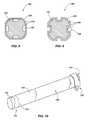
- FIG. 3is a perspective view of one example of a flare according to an embodiment of the present disclosure.
- FIG. 4is a cross-sectional view of the flare shown in FIG. 3 ;
- FIG. 5is a simplified drawing showing an enlarged view of the material within a consumable weight of an embodiment of the present disclosure
- FIG. 6is a perspective view of one example of a consumable weight and grain that may be used in a flare according to an embodiment of the present disclosure, such as the flare shown in FIGS. 3 and 4 ;
- FIG. 7Ais a front elevation view of the an embodiment of the consumable weight shown in FIG. 6 , and is also a front elevation view of the grain shown in FIG. 6 ;
- FIGS. 7B-7Eillustrate additional examples of consumable weights or grains that may be used in flares according to an embodiment of the present disclosure, such as the flare shown in FIGS. 3 and 4 ;
- FIG. 8is a cross-sectional view of a grain assembly of the flare of FIG. 4 , taken along line 8 - 8 ;
- FIG. 9is a cross-sectional view of an additional example of a grain assembly that may be used in flares according to an embodiment of the present disclosure.
- FIG. 10is a perspective view of another example of a flare according to an embodiment of the present disclosure.
- a flare having a consumable weight componentis disclosed.
- the term “consumable”means and includes a material that is used up during use and operation of the flare. During use and operation of the flare, combustion of the consumable weight produces at least one of gaseous byproducts, a friable material, and unreacted material, thus, consuming the consumable weight.
- the consumable weightprovides weight and stability to a forward portion of the flare during launch and flight of the flare.
- the terms “forward end,” “forward portion,” or “forward weight” of a flaredenotes the leading end of the flare when ejected from a vehicle for use, which vehicle may be in flight, and may be characterized as the leading portion or end of the flare.
- the term “forward end” of a graindenotes a leading end of the grain during flight, which leading end may be attached to a consumable weight according to an embodiment of the disclosure.
- the consumable weightis formed from an energetic material such that the consumable weight combusts during use and operation of the flare.
- the consumable weightmay, ultimately, be consumed by converting the consumable material to at least one of the gaseous byproducts, friable material, and unreacted material.
- the friable materialmay disperse into ash or small particles that do not pose a danger to airborne aircraft or ground-based buildings, vehicles, or personnel, and the unreacted material may be in the form of small particles that do not pose a danger to airborne aircraft or ground-based buildings, vehicles, or personnel.
- the nature of the combustion products (i.e., the gaseous byproducts, friable material, and unreacted material) of the consumable weightmay reduce the amount of falling debris compared to that obtained using conventional forward weights in conventional flares.
- the flare 110includes a grain assembly 120 that may be disposed within a casing 112 .
- the grain assembly 120includes a grain 122 of combustible material and a first-fire material (e.g., a reactive foil 124 , discussed below) positioned relative to the grain 122 .
- the combustible material of the grain 122may have a composition of a conventional decoy flare grain.
- Such a grain 122may include, for example, magnesium and a fluoropolymer-based material. Adding additional metals or other elements to the combustible material of the grain 122 may alter the peak emission wavelength emitted by the flare 110 .
- both the grain 122 of the grain assembly 120 and the casing 112may have an elongated shape.
- the casing 112may have a first end 114 , i.e., an aft end, and a second end 116 , i.e., a forward end opposite the aft end.
- the grain 122 of the grain assembly 120may have an aft end 123 A and a forward end 123 B.
- the grain 122 of the grain assembly 120may be initially positioned within the case 112 such that the aft end 123 A of the grain 122 is proximate to the first end 114 of the casing 112 and such that the forward end 123 B of the grain 122 is proximate to the second end 116 of the casing 112 .
- a consumable weight 143(i.e., a forward weight) may, along with the grain 122 , be initially positioned within the casing 112 proximate to the second end 116 of the casing 112 .
- An end cap 140may, at least initially, enclose the consumable weight 143 within the casing 112 .
- the end cap 140may be a plastic end cap and may therefore be lighter weight and less expensive than conventional weighted end caps 40 ( FIGS. 1 and 2 ).
- the end cap 140may be configured to protect the consumable weight 143 , the grain 122 , and other components of the flare 110 from coming into unwanted contact with sparks or other igniting materials.
- the consumable weight 143may be formed from a metal material dispersed in a matrix.
- FIG. 5illustrates the consumable weight 143 in a simplified, enlarged view.
- the consumable weight 143may include matrix 202 , which is an incinerable material, and metal material 200 within the matrix 202 .
- the metal material 200may be a metal-containing material, such as a metal, a metal oxide, a metal-containing compound, or the metal material 200 may be a metal-like material (i.e., a material exhibiting a density and resistance to burning like that of a metal, metal oxide, or metal-containing compound).
- the metal material 200does not burn or incinerate relative to the material of the matrix 202 .
- a temperature at which the metal material 200 burnsis greater than a temperature at which the matrix 202 burns.
- the metal material 200may be in the form of metal particles, a metal powder, or other non-consumable fill powder.
- the metal material 200may exhibit an average particle size equal to or less than about 60 micrometers, such as from about 30 micrometers to about 50 micrometers.
- the metal material 200may exhibit an average particle size larger than about 60 micrometers, though still exhibiting a particle size configured to be small enough not pose a danger to airborne aircraft or ground-based buildings, vehicles, or personnel once the matrix 202 of the consumable weight 143 has been consumed.
- the metal material 200may be any of tungsten, bismuth, lead, tantalum, tungsten carbide, a metal oxide, an alloy thereof, and a combination thereof.
- the metal oxidemay be any of tungsten oxide, bismuth oxide, lead oxide, tantalum oxide, and a combination thereof.
- the consumable weight 143may have a density greater than or equal to the density of brass (8.4 grams per cubic centimeter to 8.73 grams per cubic centimeter).
- the metal material 200may have a density of about 19.3 grams per cubic centimeter, and the consumable weight 143 may have a density greater than or about equal to (e.g., not significantly lower than) the density of brass.
- the metal material 200may account for between about 50 weight percent and about 98 weight percent of a total weight of the consumable weight 143 .
- the consumable weight 143may be substantially nonreactive in that the material does not react upon impact of the flare 110 with a target.
- the matrix 202 of the consumable weight 143may account for between 2 weight percent and about 50 weight percent of the weight of the consumable weight 143 .
- the matrix 202 of the consumable weight 143may include a binder, such as a polymer binder.
- the bindermay be a curable polymer that is a liquid at a processing temperature of the consumable weight 143 .
- the bindermay include, partially or entirely, a solid or solids at room temperature (i.e., about 20 degrees Celsius).
- the bindermay be an energetic or a nonenergetic material.
- the binder of the matrix 202may include an energetic binder, such as glycidyl azide polymer (GAP) or nitrocellulose (NC).
- GAPglycidyl azide polymer
- NCnitrocellulose
- the bindermay alternatively or additionally include a nonenergetic binder, such as polyethylene glycol (PEG), polypropylene glycol (PPG), polybutadiene acrylonitrile (PBAN), hydroxyl-terminated polybutadiene (HTPB), cellulose acetate butyrate (CAB), carboxyl-terminated polyethylene glycol succinate polyester resin, a fluoroelastomer (e.g., VITON®), a fluorinated thermoplastic polymer (e.g., THV 220), a co-polymer thereof, or a combination thereof.
- a nonenergetic bindersuch as polyethylene glycol (PEG), polypropylene glycol (PPG), polybutadiene acrylonitrile (PBAN), hydroxyl-terminated polybutadiene (HTPB), cellulose acetate butyrate (CAB), carboxyl-terminated polyethylene glycol succinate polyester resin, a fluoroelastomer (e.g., VITON®
- the matrix 202may, optionally, include at least one of a plasticizer, an oxidizer, a burn rate catalyst, or other additives configured to provide the consumable weight 143 with a desired spectral emission during incineration of the matrix 202 , a desired burn rate, ballistic performance, a desired intensity of the emitted light or heat, or other properties.
- the matrix 202may also include at least one of the above-mentioned additives to provide the desired safety, mechanical, ignition, processing, or curing properties to the consumable weight 143 .
- the matrix 202 of the consumable weight 143may include up to about 15 weight percent plasticizer (i.e., from 0 weight percent to about 15 weight percent plasticizer), up to about 20 weight percent oxidizer (i.e., from 0 weight percent to about 20 weight percent oxidizer), up to 5 weight percent burn rate catalyst (i.e., from 0 weight percent to about 5 weight percent burn rate catalyst), or any combination thereof, wherein the weight percentages are based on the weight of the consumable weight 143 .
- the plasticizermay be energetic or inert.
- An energetic plasticizermay include, for example and without limitation, glycidyl azide polymer (GAP); 1,2,4-butanetriol trinitrate (BTTN); bis(2,2-dinitropropyl)formal (BDNPF); bis(2,2-dinitropropyl)acetal (BDNPA); 1:1 mixture of BDNPF and BDNPA (BDNPA/F); nitroglycerine (NG); butyl nitroxyethylnitramine (BuNENA); other known energetic plasticizers, or combinations thereof.
- GAPglycidyl azide polymer
- BTTN1,2,4-butanetriol trinitrate
- BDNPFbis(2,2-dinitropropyl)formal
- BDNPAbis(2,2-dinitropropyl)acetal
- BDNPA/F1:1 mixture of BDNPF and BDNPA
- NGnitroglycerine
- BuNENAbutyl nitroxyethylnitramine
- An inert plasticizermay include, for example and without limitation, isodecyl pelargonate (IDP), dioctyl adipate (DOA), other known inert plasticizers, or combinations thereof.
- the oxidizermay include, for example and without limitation, strontium nitrate, potassium nitrate, cesium nitrate, sodium nitrate, a perchlorate, other known oxidizers, or combinations thereof.
- the burn rate catalystmay include, for example and without limitation, iron oxide, a conductive carbon, other known burn rate catalysts, or combinations thereof.
- the matrix 202includes a GAP binder and at least one of a GAP plasticizer, strontium nitrate as the oxidizer, and iron oxide as the burn rate catalyst.
- the consumable weight 143may include this matrix 202 and tungsten as the metal material 200 .
- the grain 122 used with the consumable weight 143 of some such embodimentsmay also include GAP.
- the matrix 202is GAP and the metal material 200 is tungsten.
- the consumable weight 143may be sized and configured to have a weight about equal to the weight of a conventional weighted end cap 40 ( FIGS. 1 and 2 ), be sized and configured such that the weight ratio of the consumable weight 143 to the grain 122 is about equal to the weight ratio of a conventional weighted end cap 40 to a conventional grain assembly 20 , or both.
- a conventional brass weighted end cap 40may weigh about 40 grams
- a conventional grain assembly 20may weigh approximately 120 to 135 grams, such that the weight ratio of the conventional weighted end cap 40 to the conventional grain assembly 20 is about 1:3. Therefore, the flare 110 of the present disclosure may be sized and configured such that the consumable weight 143 weighs about a third the weight of the grain 122 and first-fire material (e.g., reactive foil 124 ).
- the consumable weight 143 of the present flare 110may be sized and configured to provide a stable trajectory of the flare 110 during use.
- the density of the consumable weight 143may be selected and formulated to be greater than or about equal to the density of a conventional brass weighted end cap 40 . Accordingly, the consumable weight 143 may be formulated to have a density greater than or equal to about 8.4 grams per cubic centimeter to about 8.73 grams per cubic center centimeter. In other embodiments, the consumable weight 143 may have a density less than about 8.4 grams per cubic centimeter.
- the consumable weight 143may be formulated and configured such that the density is essentially uniform throughout the consumable weight 143 .
- the consumable weight 143may be formulated such that the metal material 200 is essentially uniformly distributed in the matrix 202 in which the metal material 200 is dispersed.
- the metal material 200may be more densely distributed in the matrix 202 proximate to a front side 145 A ( FIG. 6 ) of the consumable weight 143 .
- FIG. 6illustrates the consumable weight 143 and the grain 122 of a flare 110 separated from one another.
- the consumable weight 143may be formed by casting processes, curing processes, compressive processes, extrusion processes, or other processes used to form conventional flare grains.
- the consumable weight 143may be connected proximate to the forward end 123 B of the grain 122 .
- the consumable weight 143may be connected directly to the forward end 123 B of the grain 122 .
- a rear side 145 B of the consumable weight 143may be joined to the forward end 123 B of the grain 122 .
- the consumable weight 143may be joined to the grain 122 along an interface 141 ( FIG.
- the consumable weight 143may be seamlessly integrated with the grain 122 . Accordingly, in forming the flare 110 , in some embodiments, the consumable weight 143 and the grain 122 may be formed simultaneously, e.g., co-cured, to form a unified flare 110 . In other embodiments, the consumable weight 143 may be separately formed and later attached to the grain 122 , such as by adhering (i.e., bonding) the consumable weight 143 to the grain 122 . The binder in the matrix 202 of the consumable weight 143 may provide sufficient adhesion to join the consumable weight 143 to the grain 122 .
- an adhesive compositionmay be used to join the consumable weight 143 and the grain 122 .
- the binder of the matrix 202is the same as a binder within the grain 122 , improving adhesion between the consumable weight 143 and the grain 122 .
- the consumable weight 143 and the grain 122may be formed using conventional grain-forming methods, whether formed together or formed separately and then joined.
- the consumable weight 143 and the grain 122may be formed into desired shapes or configurations by casting, pressing, extrusion, molding, curing, machining, or other conventional techniques.
- a separately formed consumable weight 143may be retrofitted to a conventional grain 22 ( FIGS. 1 and 2 ) of a conventional flare 10 to replace the conventional weighted end cap 40 .
- the consumable weight 143may be formed to be about the same size and shape as the conventional weighted end cap 40 such that the consumable weight 143 , according to embodiments of the present disclosure, may be attached to a conventional grain 22 and used in a conventional casing 12 .
- the consumable weight 143may be a drop-in replacement for the conventional weighted end cap 40 of the conventional flare 10 . Therefore, the consumable weight 143 may be adherable to a grain 122 of a flare 110 .
- FIGS. 3 , 4 , and 6show that no portion of the consumable weight 143 is received within a portion of the grain 122
- the consumable weight 143may be attached to the grain 122 by an elongated rod (e.g., elongated rod 42 ( FIG. 2 )).
- the elongated rodis connected to the consumable weight 143 and received within an internal bore 144 defined in the grain 122 .
- the consumable weight 143may be formed so as to have a cross-sectional shape similar or identical to the cross-sectional shape of the grain 122 .
- FIGS. 7A through 7Eillustrate a variety of cross-sectional shapes in which the consumable weight 143 and/or the grain 122 may be formed.
- the consumable weight 143 , the grain 122 , 122 ′, 122 ′′, 122 ′′′, 122 ′′′′, or bothmay include one or more grooves 126 , 126 ′, 126 ′′′′ along exterior lateral surfaces 128 .
- the consumable weight 143 , the grain 122 , 122 ′, 122 ′′, 122 ′′′, 122 ′′′′, or bothmay, optionally, include an internal bore 144 configured to receive an elongated rod. Therefore, the consumable weight 143 may have a cross-sectional shape of a conventional grain 22 ( FIGS. 1 and 2 ), regardless of whether the internal bore 144 is utilized to receive the elongated rod.
- the internal bore 144along with the grooves 126 , 126 ′, 126 ′′′′ may be configured to enable combustion, incineration, or both of the material forming the grain 122 , 122 ′, 122 ′′, 122 ′′′, 122 ′′′′, the matrix 202 , or both of the consumable weight 143 .
- the consumable weight 143 , the grain 122 ′′′′, or bothdo not include an internal bore 144 .
- exterior lateral surfaces 128 of the consumable weight 143 and/or grain 122may be surrounded, at least partially, by a first-fire material such as a reactive foil 124 .
- This first-fire materialis included within the grain assembly 120 of the flare 110 .
- the reactive foil 124 of the grain assembly 120may come into direct contact with only some of exterior lateral surfaces 128 of the consumable weight 143 , the grain 122 , or both.
- the reactive foil 124 of the grain assembly 120 ′may be in direct contact with all exterior lateral surfaces 128 of the consumable weight 143 , the grain 122 , or both.
- FIGS. 8 and 9depict the grain assembly 120 , 120 ′ with reactive foil 124 in connection with the grain 122
- a front elevation or cross-sectional view of the consumable weight 143 in connection with the reactive foil 124would be an equivalent view to those depicted in FIGS. 8 and 9 of the grain assembly 120 , 120 ′.
- the first-fire materialmay include combustible powders, slurries, sol-gel compositions, or any combination thereof.
- the first-fire materialmay be configured to enable ignition of one or both of the grain 122 and the matrix 202 of the consumable weight 143 .
- an impulse charge device 130may be provided at or within the first end 114 of the casing 112 , although, in some embodiments, such an impulse charge device 130 may not be coupled to the flare 110 until the flare 110 is ready to be deployed (e.g., if the flare 110 includes a decoy flare, the impulse charge device 130 may not be coupled to the flare 110 until the flare 110 is mounted in an aircraft).
- the impulse charge device 130may be configured to force the grain assembly 120 , with consumable weight 143 attached thereto, out from the second end 116 of the casing 112 upon ignition of the impulse charge device 130 .
- the decoy flare 110may include a piston member 132 disposed within the casing 112 between the impulse charge device 130 and the grain assembly 120 .
- the piston member 132may be part of an ignition assembly 136 (often referred to in the art as an “ignition sequence assembly,” a “safe and arm igniter,” or a “safe and arm ignition assembly”).
- the flare 110may include an ignition assembly 136 having a mechanism configured to prevent ignition of the reactive foil 124 (or other first-fire material), the grain 122 , and the consumable weight 143 until the grain assembly 120 and consumable weight 143 have been substantially ejected from the casing 112 by the impulse charge device 130 .
- the flare 110may include an ignition assembly 136 that is configured to cause ignition of the reactive foil 124 , or other first-fire material, and the grain 122 before the grain assembly 120 and consumable weight 143 have been substantially ejected from the casing 112 by the impulse charge device 130 , or as the grain assembly 120 and consumable weight 143 are being ejected from the casing 112 by the impulse charge device 130 .
- the ignition assembly 136may include a first igniter material 134 of combustible material that is attached or coupled to the piston member 132 .
- the first igniter material 134may include, for example, a boron- or magnesium-based material.
- Combustion of the first igniter material 134may be initiated upon ignition of the impulse charge device 130 , and combustion of the first igniter material 134 may cause ignition of the grain assembly 120 .
- combustion of the first igniter material 134may cause ignition of the first-fire material, e.g., the reactive foil 124
- the reactive foil 124may cause ignition of the grain 122 .
- the first-fire material, e.g., the reactive foil 124may also cause ignition of the consumable weight 143 .
- the combustion of the grain 122may cause ignition of the consumable weight 143 .
- Combustion of the grain 122may cause ignition of the consumable weight 143 after the grain assembly 120 and the consumable weight 143 have been ejected from the casing 112 .
- the grain 122may be ignited to consume the combustible material of the grain 122 , and the consumable weight 143 may be ignited to incinerate the matrix 202 ( FIG. 5 ). Incinerating the matrix 202 may release the metal material 200 .
- the metal material 200may not be consumed during use and operation but may fall to the ground as particles (e.g., solid particles, friable particles, metal particles, metal oxide particles, or the like) that are relatively harmless to airborne aircraft or ground-based buildings, vehicles, or personnel.
- the consumable weight 143may be configured so that the matrix 202 will complete incineration only after the grain 122 has been fully consumed.
- the burn rate of the consumable weight 143may be tailored such that the consumable weight 143 provides stability and weight to the forward end of the flare 110 during use and operation of the flare 110 .
- the burn ratemay be sufficiently fast that the consumable weight 143 is substantially consumed (i.e., the gaseous byproducts, the friable material, the unreacted products, or any combination thereof are produced) before contacting airborne aircraft or ground-based buildings, vehicles, or personnel.
- the consumable weight 143upon combustion, may break into particles or ash of a sufficient size that the particles or ash do not damage airborne aircraft or ground-based personnel or other property.
- the flare 110may produce minimal amounts of debris that pose a danger to airborne aircraft or ground-based personnel or other property.
- the flare 110may be configured to be released from an airborne aircraft. In other embodiments, the flare 110 may be configured to be surface deployed so as to be projected into the air by an earth-supported device.
- the flare 110may be, for example, a propulsive flare or a low thrust decoy flare.
- the flare 110may be configured such that ignition of the grain 122 will result in substantially full consumption of the combustible material of the grain 122 and such that ignition of the consumable weight 143 will result in incineration of substantially all of the matrix 202 of the consumable weight 143 before combustion products of the consumable weight 143 come into contact with airborne aircraft or any earth-supported object, such as buildings on the ground, people on the ground, watercraft in bodies of water, people in bodies of water, or the ground surface itself.
- the combustion products of the consumable weight 143following incineration of the matrix 202 , may include the gaseous byproducts, the friable material, such as ash, and unreacted products, such as the metal material 200 .
- the gaseous byproductsmay include, among other byproducts, carbon dioxide, carbon monoxide, water, or combinations thereof.
- smoke or lightmay be produced.
- the combustion productsdo not include the casing 112 , which may be configured to be retained within the aircraft when the flare 110 is released. Therefore, the flare 110 is configured such that low amounts of debris are produced from the combustion of its components, which are unlikely to cause damage if ingested in engines of aircraft flying below or behind the aircraft from which the flare 110 is released and are unlikely to cause injury or damage to earth-supported objects, including people.
- the consumable weight 143may be used in other projectiles having weighted components (i.e., brass or other metal components) such that a reduction in falling debris from brass or other metal components in the projectiles is achieved.
- the metal material 200may be formed of fine pieces of material, such as a metal powder. Therefore, when the metal material 200 is released by the incineration of the matrix 202 , the combustion products of the consumable weight 143 include fine pieces of the non-consumed metal material 200 and ash from the incinerated matrix 202 . Thus, the likelihood of unwanted contact between falling solid debris and other aircraft, people, or objects below is minimized or greatly reduced compared to the conventional flare 10 ( FIGS. 1 and 2 ) in which consumption of the grain 22 leaves a falling, essentially-solid, weighted end cap 40 .
- the metal material 200may exhibit an average particle size equal or less than about 60 micrometers.
- the metal material 200may exhibit an average particle size in the range of from about 30 micrometers to about 50 micrometers, inclusive.
- the combustion products of the consumable weight 143 following incinerationmay, therefore, include solid matter not exceeding about 60 micrometers in average particle size, e.g., solid matter with an average particle size in the range of from about 30 micrometers to about 50 micrometers.
- the metal material 200may exhibit an average particle size larger than about 60 micrometers, though still exhibiting a particle size configured to result in combustion products of the consumable weight 143 , following incineration, that include solid matter of a small enough particle size, in light of the weight, friability, density, or other properties of the solid matter, that will not pose a danger to airborne aircraft or ground-based buildings, vehicles, or personnel.
- the flare 110may be configured as a decoy flare, and the combustible material of the grain 122 and/or the matrix 202 of the consumable weight 143 may be configured to emit electromagnetic radiation (upon combustion of the grain 122 , consumable weight 143 , or both) having a peak emission wavelength within the infrared region of the electromagnetic radiation spectrum (i.e., between about 0.7 microns and about 100 microns).
- the flare 110may be configured for signaling, illumination, or both, and may be configured to emit a peak emission wavelength within the visible region of the electromagnetic radiation spectrum (i.e., between about 400 nanometers and about 700 nanometers).
- the flare 110may be configured to emit a peak emission wavelength within the ultraviolet region of the electromagnetic radiation spectrum.
- the composition of the consumable weight 143may be selected so as to achieve the desired electromagnetic radiation emissions, the desired burn rate, and other properties of an ignited flare 110 .
- FIG. 10illustrates another embodiment of the grain assembly 120 of the flare 110 to which the ignition assembly 136 is attached.
- the first fire materiale.g., the reactive foil 124 covers the grain 122 ( FIG. 4 ) of the grain assembly 120 as well as the consumable weight 143 .
- the illustrated grain assembly 120 and consumable weight 143are configured to be positioned within a casing 112 ( FIG. 4 ) prior to ignition.
- a flarea forward weight, a composition of a nonreactive material, a method for fabricating a flare, and a method for using a flare.
Landscapes
- Engineering & Computer Science (AREA)
- Chemical & Material Sciences (AREA)
- Organic Chemistry (AREA)
- Mechanical Engineering (AREA)
- General Engineering & Computer Science (AREA)
- Dispersion Chemistry (AREA)
- Health & Medical Sciences (AREA)
- Life Sciences & Earth Sciences (AREA)
- Molecular Biology (AREA)
- Crystallography & Structural Chemistry (AREA)
- Metallurgy (AREA)
- Combustion & Propulsion (AREA)
- Compositions Of Macromolecular Compounds (AREA)
- Preliminary Treatment Of Fibers (AREA)
- Earth Drilling (AREA)
Abstract
Description
Claims (26)
Priority Applications (4)
| Application Number | Priority Date | Filing Date | Title |
|---|---|---|---|
| US13/289,669US9194669B2 (en) | 2011-11-04 | 2011-11-04 | Flares with a consumable weight and methods of fabrication and use |
| PCT/US2012/062954WO2013115865A2 (en) | 2011-11-04 | 2012-11-01 | Flares, consumable weight components thereof, and methods of fabrication and use |
| US14/949,702US10155700B2 (en) | 2011-11-04 | 2015-11-23 | Consumable weight components for flares and methods of formation |
| US16/169,073US10647620B2 (en) | 2011-11-04 | 2018-10-24 | Consumable weight components for flares and related flares |
Applications Claiming Priority (1)
| Application Number | Priority Date | Filing Date | Title |
|---|---|---|---|
| US13/289,669US9194669B2 (en) | 2011-11-04 | 2011-11-04 | Flares with a consumable weight and methods of fabrication and use |
Related Child Applications (1)
| Application Number | Title | Priority Date | Filing Date |
|---|---|---|---|
| US14/949,702DivisionUS10155700B2 (en) | 2011-11-04 | 2015-11-23 | Consumable weight components for flares and methods of formation |
Publications (2)
| Publication Number | Publication Date |
|---|---|
| US20130112099A1 US20130112099A1 (en) | 2013-05-09 |
| US9194669B2true US9194669B2 (en) | 2015-11-24 |
Family
ID=48222820
Family Applications (3)
| Application Number | Title | Priority Date | Filing Date |
|---|---|---|---|
| US13/289,669ActiveUS9194669B2 (en) | 2011-11-04 | 2011-11-04 | Flares with a consumable weight and methods of fabrication and use |
| US14/949,702Active2032-08-24US10155700B2 (en) | 2011-11-04 | 2015-11-23 | Consumable weight components for flares and methods of formation |
| US16/169,073ActiveUS10647620B2 (en) | 2011-11-04 | 2018-10-24 | Consumable weight components for flares and related flares |
Family Applications After (2)
| Application Number | Title | Priority Date | Filing Date |
|---|---|---|---|
| US14/949,702Active2032-08-24US10155700B2 (en) | 2011-11-04 | 2015-11-23 | Consumable weight components for flares and methods of formation |
| US16/169,073ActiveUS10647620B2 (en) | 2011-11-04 | 2018-10-24 | Consumable weight components for flares and related flares |
Country Status (2)
| Country | Link |
|---|---|
| US (3) | US9194669B2 (en) |
| WO (1) | WO2013115865A2 (en) |
Cited By (2)
| Publication number | Priority date | Publication date | Assignee | Title |
|---|---|---|---|---|
| US9726466B2 (en)* | 2015-02-13 | 2017-08-08 | Dmd Systems, Llc | Fuel/air concussion apparatus |
| US11073366B2 (en) | 2019-12-24 | 2021-07-27 | Northrop Grumman Systems Corporation | Liners for flares and related methods |
Families Citing this family (5)
| Publication number | Priority date | Publication date | Assignee | Title |
|---|---|---|---|---|
| EP2422162B1 (en)* | 2009-04-21 | 2018-05-30 | Kilgore Flares Company, LLC | Low foreign object damage (fod) weighted nose decoy flare |
| US9194669B2 (en) | 2011-11-04 | 2015-11-24 | Orbital Atk, Inc. | Flares with a consumable weight and methods of fabrication and use |
| US9702670B2 (en)* | 2012-08-21 | 2017-07-11 | Omnitek Partners Llc | Countermeasure flares |
| FR3018112B1 (en)* | 2014-03-03 | 2018-04-20 | Etienne Lacroix Tous Artifices S.A. | AIRCRAFT SANDING CARTRIDGE |
| CN111380411A (en)* | 2018-12-27 | 2020-07-07 | 湖南尚花科技有限公司 | Firework driving system and firework driving method |
Citations (50)
| Publication number | Priority date | Publication date | Assignee | Title |
|---|---|---|---|---|
| US3323456A (en) | 1965-08-09 | 1967-06-06 | Rothman Barry | Cartridge having flash and noise projectile |
| US3565706A (en) | 1968-01-19 | 1971-02-23 | Hal R Waite | Incendiary composition containing a metallic fuel and a solid fluoro-carbon polymer |
| US3605624A (en) | 1969-02-10 | 1971-09-20 | Thiokol Chemical Corp | Castable illuminant flare composition and method for making flare body therewith |
| US3680483A (en) | 1970-10-06 | 1972-08-01 | Dow Chemical Co | Annular flare grains |
| US3715248A (en) | 1970-12-15 | 1973-02-06 | Us Army | Castable metallic illuminant fuel containing nitrocellulose plasticized binder |
| US3779008A (en) | 1970-12-15 | 1973-12-18 | Atlantic Res Corp | Electrophillic gas generating compositions and process |
| US3788908A (en) | 1972-09-07 | 1974-01-29 | Ethyl Corp | Tracer incendiary composition of alkylaluminum,inorganic oxidizer,and zirconium |
| US3983816A (en) | 1974-01-16 | 1976-10-05 | Thiokol Corporation | Compositions for producing flickering signals |
| US4078954A (en) | 1975-07-03 | 1978-03-14 | Societe Nationale Des Poudres Et Explosifs | Illuminating pyrotechnic composition which generates gases |
| US4131498A (en) | 1978-01-25 | 1978-12-26 | Teledyne Industries, Inc. | Metallic sponge incendiary compositions |
| US4505203A (en)* | 1983-02-04 | 1985-03-19 | Honeywell Inc. | Frangible ballast |
| EP0309097A1 (en) | 1987-09-03 | 1989-03-29 | Loral Corporation | Infrared signature enhancement decoy |
| US5056435A (en) | 1989-11-29 | 1991-10-15 | Jones Leon L | Infrared illuminant and pressing method |
| US5071497A (en) | 1991-03-19 | 1991-12-10 | The United States Of America As Represented By The Secretary Of The Army | Composition for use in flares |
| US5237927A (en) | 1991-10-21 | 1993-08-24 | Olin Corporation | Energetic consumable cartridge case |
| WO1995009824A1 (en) | 1993-10-06 | 1995-04-13 | Thiokol Corporation | Bamo/ammo propellant formulations |
| US5561260A (en) | 1991-10-01 | 1996-10-01 | The Secretary Of State For Defence In Her Britannic Majesty's Government Of The United Kingdom Of Great Britain And Northern Ireland | Propelled pyrotechnic decoy flare |
| US5587552A (en) | 1993-11-09 | 1996-12-24 | Thiokol Corporation | Infrared illuminating composition |
| US5700974A (en) | 1995-09-25 | 1997-12-23 | Morton International, Inc. | Preparing consolidated thermite compositions |
| US5739460A (en) | 1996-05-14 | 1998-04-14 | Talley Defense Systems, Inc. | Method of safely initiating combustion of a gas generant composition using an autoignition composition |
| US5834680A (en) | 1995-09-22 | 1998-11-10 | Cordant Technologies Inc. | Black body decoy flare compositions for thrusted applications and methods of use |
| WO1998050755A1 (en) | 1997-05-07 | 1998-11-12 | Particia Farnell | Infrared illuminating compositions and articles |
| US5886293A (en) | 1998-02-25 | 1999-03-23 | The United States Of America As Represented By The Secretary Of The Navy | Preparation of magnesium-fluoropolymer pyrotechnic material |
| US5912430A (en) | 1992-07-15 | 1999-06-15 | Cordant Technologies Inc. | Pressable infrared illuminant compositions |
| US6039820A (en) | 1997-07-24 | 2000-03-21 | Cordant Technologies Inc. | Metal complexes for use as gas generants |
| US6123789A (en) | 1992-07-15 | 2000-09-26 | Cordant Technologies Inc. | Castable infrared illuminant compositions |
| US6224099B1 (en) | 1997-07-22 | 2001-05-01 | Cordant Technologies Inc. | Supplemental-restraint-system gas generating device with water-soluble polymeric binder |
| US6230628B1 (en) | 1998-10-29 | 2001-05-15 | The United States Of America As Represented By The Secretary Of The Army | Infrared illumination compositions and articles containing the same |
| US6432231B1 (en) | 1996-11-15 | 2002-08-13 | Alliant Techsystems Inc. | Extrudable black body decoy flare compositions |
| US6599379B2 (en) | 2001-04-12 | 2003-07-29 | Dmd Systems, Llc | Low-smoke nitroguanidine and nitrocellulose based pyrotechnic compositions |
| US6679176B1 (en) | 2000-03-21 | 2004-01-20 | Peter D. Zavitsanos | Reactive projectiles for exploding unexploded ordnance |
| US20040112242A1 (en) | 2002-10-21 | 2004-06-17 | Michael Brunn | Super long range crash-bang round |
| US6962634B2 (en) | 2002-03-28 | 2005-11-08 | Alliant Techsystems Inc. | Low temperature, extrudable, high density reactive materials |
| US6969435B1 (en) | 1994-01-19 | 2005-11-29 | Alliant Techsystems Inc. | Metal complexes for use as gas generants |
| US20060225599A1 (en) | 2004-11-22 | 2006-10-12 | Giat Industries | Piece of ammunition or ammunition component comprising a structural energetic material |
| US7194961B1 (en) | 2004-02-10 | 2007-03-27 | The United States Of America As Represented By The Secretary Of The Navy | Reactive composite projectiles with improved performance |
| US20070295236A1 (en) | 2000-12-13 | 2007-12-27 | Callaway James D | Infra-red emitting decoy flare |
| US20080134926A1 (en) | 2006-09-28 | 2008-06-12 | Nielson Daniel B | Flares including reactive foil for igniting a combustible grain thereof and methods of fabricating and igniting such flares |
| US7556702B2 (en) | 2004-05-19 | 2009-07-07 | Diehl Bgt Defence Gmbh & Co., Kg | Pyrotechnic charge |
| US20100024932A1 (en) | 2007-04-16 | 2010-02-04 | Rutger Webb | Low-smoke pyrotechnic composition for producing colored flames |
| US20100024931A1 (en) | 2007-04-16 | 2010-02-04 | Zevenbergen John Franciscus | Pyrotechnic colour composition |
| US20100139823A1 (en) | 2008-12-05 | 2010-06-10 | Gash Alexander E | Pyrophoric metal-carbon foam composites and methods of making the same |
| US20100212533A1 (en) | 2002-10-21 | 2010-08-26 | Michael Brunn | Flare-bang projectile |
| WO2010123955A1 (en) | 2009-04-21 | 2010-10-28 | Kilgore Flares Company, Llc | Low foreign object damage (fod) weighted nose decoy flare |
| US7866265B1 (en) | 2006-06-30 | 2011-01-11 | Jacob Kravel | Flare apparatus |
| US7887651B1 (en) | 2005-11-24 | 2011-02-15 | Eurenco | Semi-continuous two-component method for obtaining a composite explosive charge with polyurethane matrix |
| US7886668B2 (en) | 2006-06-06 | 2011-02-15 | Lockheed Martin Corporation | Metal matrix composite energetic structures |
| US7923662B2 (en) | 2004-05-20 | 2011-04-12 | Alexza Pharmaceuticals, Inc. | Stable initiator compositions and igniters |
| US8418619B1 (en)* | 2008-01-03 | 2013-04-16 | Kilgore Flares Company, Llc | Kinematic countermeasure |
| WO2013115865A2 (en)* | 2011-11-04 | 2013-08-08 | Alliant Techsystems Inc. | Flares, consumable weight components thereof, and methods of fabrication and use |
Family Cites Families (3)
| Publication number | Priority date | Publication date | Assignee | Title |
|---|---|---|---|---|
| USH925H (en) | 1989-11-22 | 1991-06-04 | The United States Of America As Represented By The Secretary Of The Army | Encapsulated signal illumination flare composition |
| CA2351002C (en)* | 2000-06-27 | 2009-04-07 | The Minister Of National Defence | Insensitive melt cast explosive compositions containing energetic thermoplastic elastomers |
| NL1029465C2 (en)* | 2005-07-06 | 2007-01-09 | Tno | A pyrotechnic composition. |
- 2011
- 2011-11-04USUS13/289,669patent/US9194669B2/enactiveActive
- 2012
- 2012-11-01WOPCT/US2012/062954patent/WO2013115865A2/enactiveApplication Filing
- 2015
- 2015-11-23USUS14/949,702patent/US10155700B2/enactiveActive
- 2018
- 2018-10-24USUS16/169,073patent/US10647620B2/enactiveActive
Patent Citations (58)
| Publication number | Priority date | Publication date | Assignee | Title |
|---|---|---|---|---|
| US3323456A (en) | 1965-08-09 | 1967-06-06 | Rothman Barry | Cartridge having flash and noise projectile |
| US3565706A (en) | 1968-01-19 | 1971-02-23 | Hal R Waite | Incendiary composition containing a metallic fuel and a solid fluoro-carbon polymer |
| US3605624A (en) | 1969-02-10 | 1971-09-20 | Thiokol Chemical Corp | Castable illuminant flare composition and method for making flare body therewith |
| US3680483A (en) | 1970-10-06 | 1972-08-01 | Dow Chemical Co | Annular flare grains |
| US3715248A (en) | 1970-12-15 | 1973-02-06 | Us Army | Castable metallic illuminant fuel containing nitrocellulose plasticized binder |
| US3779008A (en) | 1970-12-15 | 1973-12-18 | Atlantic Res Corp | Electrophillic gas generating compositions and process |
| US3788908A (en) | 1972-09-07 | 1974-01-29 | Ethyl Corp | Tracer incendiary composition of alkylaluminum,inorganic oxidizer,and zirconium |
| US3983816A (en) | 1974-01-16 | 1976-10-05 | Thiokol Corporation | Compositions for producing flickering signals |
| US4078954A (en) | 1975-07-03 | 1978-03-14 | Societe Nationale Des Poudres Et Explosifs | Illuminating pyrotechnic composition which generates gases |
| US4131498A (en) | 1978-01-25 | 1978-12-26 | Teledyne Industries, Inc. | Metallic sponge incendiary compositions |
| US4505203A (en)* | 1983-02-04 | 1985-03-19 | Honeywell Inc. | Frangible ballast |
| US5074216A (en)* | 1987-09-03 | 1991-12-24 | Loral Corporation | Infrared signature enhancement decoy |
| EP0309097A1 (en) | 1987-09-03 | 1989-03-29 | Loral Corporation | Infrared signature enhancement decoy |
| US5056435A (en) | 1989-11-29 | 1991-10-15 | Jones Leon L | Infrared illuminant and pressing method |
| US5071497A (en) | 1991-03-19 | 1991-12-10 | The United States Of America As Represented By The Secretary Of The Army | Composition for use in flares |
| US5561260A (en) | 1991-10-01 | 1996-10-01 | The Secretary Of State For Defence In Her Britannic Majesty's Government Of The United Kingdom Of Great Britain And Northern Ireland | Propelled pyrotechnic decoy flare |
| US5237927A (en) | 1991-10-21 | 1993-08-24 | Olin Corporation | Energetic consumable cartridge case |
| US5912430A (en) | 1992-07-15 | 1999-06-15 | Cordant Technologies Inc. | Pressable infrared illuminant compositions |
| US6190475B1 (en) | 1992-07-15 | 2001-02-20 | Cordant Technologies Inc. | Castable infrared illuminant compositions |
| US6123789A (en) | 1992-07-15 | 2000-09-26 | Cordant Technologies Inc. | Castable infrared illuminant compositions |
| WO1995009824A1 (en) | 1993-10-06 | 1995-04-13 | Thiokol Corporation | Bamo/ammo propellant formulations |
| US5587552A (en) | 1993-11-09 | 1996-12-24 | Thiokol Corporation | Infrared illuminating composition |
| US6969435B1 (en) | 1994-01-19 | 2005-11-29 | Alliant Techsystems Inc. | Metal complexes for use as gas generants |
| US5834680A (en) | 1995-09-22 | 1998-11-10 | Cordant Technologies Inc. | Black body decoy flare compositions for thrusted applications and methods of use |
| US5700974A (en) | 1995-09-25 | 1997-12-23 | Morton International, Inc. | Preparing consolidated thermite compositions |
| US5739460A (en) | 1996-05-14 | 1998-04-14 | Talley Defense Systems, Inc. | Method of safely initiating combustion of a gas generant composition using an autoignition composition |
| US6432231B1 (en) | 1996-11-15 | 2002-08-13 | Alliant Techsystems Inc. | Extrudable black body decoy flare compositions |
| WO1998050755A1 (en) | 1997-05-07 | 1998-11-12 | Particia Farnell | Infrared illuminating compositions and articles |
| US6224099B1 (en) | 1997-07-22 | 2001-05-01 | Cordant Technologies Inc. | Supplemental-restraint-system gas generating device with water-soluble polymeric binder |
| US6039820A (en) | 1997-07-24 | 2000-03-21 | Cordant Technologies Inc. | Metal complexes for use as gas generants |
| US5886293A (en) | 1998-02-25 | 1999-03-23 | The United States Of America As Represented By The Secretary Of The Navy | Preparation of magnesium-fluoropolymer pyrotechnic material |
| US6230628B1 (en) | 1998-10-29 | 2001-05-15 | The United States Of America As Represented By The Secretary Of The Army | Infrared illumination compositions and articles containing the same |
| US6679176B1 (en) | 2000-03-21 | 2004-01-20 | Peter D. Zavitsanos | Reactive projectiles for exploding unexploded ordnance |
| US20070295236A1 (en) | 2000-12-13 | 2007-12-27 | Callaway James D | Infra-red emitting decoy flare |
| US6599379B2 (en) | 2001-04-12 | 2003-07-29 | Dmd Systems, Llc | Low-smoke nitroguanidine and nitrocellulose based pyrotechnic compositions |
| US6962634B2 (en) | 2002-03-28 | 2005-11-08 | Alliant Techsystems Inc. | Low temperature, extrudable, high density reactive materials |
| US7908972B2 (en)* | 2002-10-21 | 2011-03-22 | Michael Brunn | Flare-bang projectile |
| US7025001B2 (en)* | 2002-10-21 | 2006-04-11 | Combined Systems, Inc. | Super long range crash-bang round |
| US20100212533A1 (en) | 2002-10-21 | 2010-08-26 | Michael Brunn | Flare-bang projectile |
| US20040112242A1 (en) | 2002-10-21 | 2004-06-17 | Michael Brunn | Super long range crash-bang round |
| US7194961B1 (en) | 2004-02-10 | 2007-03-27 | The United States Of America As Represented By The Secretary Of The Navy | Reactive composite projectiles with improved performance |
| US7556702B2 (en) | 2004-05-19 | 2009-07-07 | Diehl Bgt Defence Gmbh & Co., Kg | Pyrotechnic charge |
| US7923662B2 (en) | 2004-05-20 | 2011-04-12 | Alexza Pharmaceuticals, Inc. | Stable initiator compositions and igniters |
| US20060225599A1 (en) | 2004-11-22 | 2006-10-12 | Giat Industries | Piece of ammunition or ammunition component comprising a structural energetic material |
| US7887651B1 (en) | 2005-11-24 | 2011-02-15 | Eurenco | Semi-continuous two-component method for obtaining a composite explosive charge with polyurethane matrix |
| US7886668B2 (en) | 2006-06-06 | 2011-02-15 | Lockheed Martin Corporation | Metal matrix composite energetic structures |
| US7866265B1 (en) | 2006-06-30 | 2011-01-11 | Jacob Kravel | Flare apparatus |
| US7469640B2 (en) | 2006-09-28 | 2008-12-30 | Alliant Techsystems Inc. | Flares including reactive foil for igniting a combustible grain thereof and methods of fabricating and igniting such flares |
| US20080134926A1 (en) | 2006-09-28 | 2008-06-12 | Nielson Daniel B | Flares including reactive foil for igniting a combustible grain thereof and methods of fabricating and igniting such flares |
| US20100024931A1 (en) | 2007-04-16 | 2010-02-04 | Zevenbergen John Franciscus | Pyrotechnic colour composition |
| US20100024932A1 (en) | 2007-04-16 | 2010-02-04 | Rutger Webb | Low-smoke pyrotechnic composition for producing colored flames |
| US8418619B1 (en)* | 2008-01-03 | 2013-04-16 | Kilgore Flares Company, Llc | Kinematic countermeasure |
| US20100139823A1 (en) | 2008-12-05 | 2010-06-10 | Gash Alexander E | Pyrophoric metal-carbon foam composites and methods of making the same |
| WO2010123955A1 (en) | 2009-04-21 | 2010-10-28 | Kilgore Flares Company, Llc | Low foreign object damage (fod) weighted nose decoy flare |
| US20110036260A1 (en) | 2009-04-21 | 2011-02-17 | Kilgore Flares Company, Llc | Low foreign object damage (fod) weighted nose decoy flare |
| US8191478B2 (en)* | 2009-04-21 | 2012-06-05 | Kilgore Flares Company, Llc | Low foreign object damage (FOD) weighted nose decoy flare |
| US8813649B1 (en)* | 2009-04-21 | 2014-08-26 | David W. Herbage | Low foreign object damage (FOD) weighted nose decoy flare |
| WO2013115865A2 (en)* | 2011-11-04 | 2013-08-08 | Alliant Techsystems Inc. | Flares, consumable weight components thereof, and methods of fabrication and use |
Non-Patent Citations (7)
| Title |
|---|
| Hunt et al., Impact ignition of nano and micron composite energetic materials, International Journal of Impact Engineering 36, 2009, pp. 842-846. |
| Hwang et al., Energetics of metal-organic interfaces; New experiments and assessment of the field, Material Science and Engineering R 64 (2009) pp. 1-31. |
| International Search Report, ISA/EP, International Application No. PCT/US2012/062954, Oct. 9, 2013, four (4) pages. |
| Kuwahara et al., Combustion of GAP Based Energetic Pyrolants, Propellants, Explosives, Pyrotechnics 25, (2000) pp. 112-116. |
| Sayles, United States Statutory Invention Registration, Reg No. H925, published Jun. 4, 1991, 6 pages. |
| Singh et al., New Energetic Materials for the Propulsion of Space Vehicles and Rockets, Advanced Center of Research in High Energy Materials (ACRHEM), University of Hyderabad, India, 10 pages. |
| Written Opinion of the International Searching Authority, ISA/EP, International Application No. PCT/US2012/062954, Oct. 9, 2013, four (4) pages. |
Cited By (3)
| Publication number | Priority date | Publication date | Assignee | Title |
|---|---|---|---|---|
| US9726466B2 (en)* | 2015-02-13 | 2017-08-08 | Dmd Systems, Llc | Fuel/air concussion apparatus |
| US10139204B2 (en)* | 2015-02-13 | 2018-11-27 | Dmd Systems Llc | Fuel/air concussion apparatus and method |
| US11073366B2 (en) | 2019-12-24 | 2021-07-27 | Northrop Grumman Systems Corporation | Liners for flares and related methods |
Also Published As
| Publication number | Publication date |
|---|---|
| US20190055170A1 (en) | 2019-02-21 |
| WO2013115865A3 (en) | 2013-11-21 |
| WO2013115865A2 (en) | 2013-08-08 |
| US10647620B2 (en) | 2020-05-12 |
| US10155700B2 (en) | 2018-12-18 |
| US20130112099A1 (en) | 2013-05-09 |
| US20160075614A1 (en) | 2016-03-17 |
Similar Documents
| Publication | Publication Date | Title |
|---|---|---|
| US10647620B2 (en) | Consumable weight components for flares and related flares | |
| US7469640B2 (en) | Flares including reactive foil for igniting a combustible grain thereof and methods of fabricating and igniting such flares | |
| US8568541B2 (en) | Reactive material compositions and projectiles containing same | |
| US9683821B2 (en) | Reactive material enhanced projectiles, devices for generating reactive material enhanced projectiles and related methods | |
| US7762195B2 (en) | Slow cook off rocket igniter | |
| US8813649B1 (en) | Low foreign object damage (FOD) weighted nose decoy flare | |
| US20120247358A1 (en) | Liners for warheads and warheads having improved liners | |
| US20190033045A1 (en) | Propellant | |
| WO2001077607A1 (en) | Projectile for the destruction of large explosive targets | |
| KR20110028263A (en) | Activation unit for zero ammo attractant | |
| RU2486452C1 (en) | Method of increasing artillery shell range and device to this end | |
| US20060225599A1 (en) | Piece of ammunition or ammunition component comprising a structural energetic material | |
| JP2005538834A (en) | Multistage gas generator and gas generator | |
| US8778104B1 (en) | Insensitive gun propellant, ammunition round assembly, armament system, and related methods | |
| JP6571357B2 (en) | Lighting composition, lighting bullet containing the lighting composition, and related methods | |
| US7807000B1 (en) | Thermobaric explosives, articles of manufacture, and methods comprising the same | |
| US7404867B2 (en) | Infrared decoy flare composition | |
| US6230626B1 (en) | Flashless MK 66 rocket motor | |
| JPH02150700A (en) | ramjet propellant | |
| RU2670464C1 (en) | Artillery shell | |
| IL314183B1 (en) | Long range artillery projectile with auxiliary energetic material for rear casing ejection | |
| JPH06147798A (en) | Base bleed bullet | |
| Koch | On the Sensitivity of Pyrotechnic Countermeasure Ammunitions | |
| AU2001229156A1 (en) | Projectile for the destruction of large explosive targets |
Legal Events
| Date | Code | Title | Description |
|---|---|---|---|
| AS | Assignment | Owner name:ALLIANT TECHSYSTEMS INC., VIRGINIA Free format text:ASSIGNMENT OF ASSIGNORS INTEREST;ASSIGNORS:WIDENER, JEFFREY F.;NIELSON, DANIEL B.;REEL/FRAME:027179/0143 Effective date:20111101 | |
| AS | Assignment | Owner name:BANK OF AMERICA, N.A., CALIFORNIA Free format text:INTELLECTUAL PROPERTY SECURITY AGREEMENT SUPPLEMENT;ASSIGNOR:ALLIANT TECHSYSTEMS INC.;REEL/FRAME:027656/0093 Effective date:20120101 | |
| AS | Assignment | Owner name:BANK OF AMERICA, N.A., CALIFORNIA Free format text:SECURITY AGREEMENT;ASSIGNORS:ALLIANT TECHSYSTEMS INC.;CALIBER COMPANY;EAGLE INDUSTRIES UNLIMITED, INC.;AND OTHERS;REEL/FRAME:031731/0281 Effective date:20131101 | |
| FEPP | Fee payment procedure | Free format text:PAYOR NUMBER ASSIGNED (ORIGINAL EVENT CODE: ASPN); ENTITY STATUS OF PATENT OWNER: LARGE ENTITY | |
| AS | Assignment | Owner name:ORBITAL ATK, INC., VIRGINIA Free format text:CHANGE OF NAME;ASSIGNOR:ALLIANT TECHSYSTEMS INC.;REEL/FRAME:035752/0471 Effective date:20150209 | |
| AS | Assignment | Owner name:WELLS FARGO BANK, NATIONAL ASSOCIATION, AS ADMINISTRATIVE AGENT, NORTH CAROLINA Free format text:SECURITY AGREEMENT;ASSIGNORS:ORBITAL ATK, INC.;ORBITAL SCIENCES CORPORATION;REEL/FRAME:036732/0170 Effective date:20150929 Owner name:WELLS FARGO BANK, NATIONAL ASSOCIATION, AS ADMINIS Free format text:SECURITY AGREEMENT;ASSIGNORS:ORBITAL ATK, INC.;ORBITAL SCIENCES CORPORATION;REEL/FRAME:036732/0170 Effective date:20150929 | |
| AS | Assignment | Owner name:ORBITAL ATK, INC. (F/K/A ALLIANT TECHSYSTEMS INC.), VIRGINIA Free format text:RELEASE BY SECURED PARTY;ASSIGNOR:BANK OF AMERICA, N.A.;REEL/FRAME:036816/0624 Effective date:20150929 Owner name:EAGLE INDUSTRIES UNLIMITED, INC., MISSOURI Free format text:RELEASE BY SECURED PARTY;ASSIGNOR:BANK OF AMERICA, N.A.;REEL/FRAME:036816/0624 Effective date:20150929 Owner name:AMMUNITION ACCESSORIES, INC., ALABAMA Free format text:RELEASE BY SECURED PARTY;ASSIGNOR:BANK OF AMERICA, N.A.;REEL/FRAME:036816/0624 Effective date:20150929 Owner name:ORBITAL ATK, INC. (F/K/A ALLIANT TECHSYSTEMS INC.) Free format text:RELEASE BY SECURED PARTY;ASSIGNOR:BANK OF AMERICA, N.A.;REEL/FRAME:036816/0624 Effective date:20150929 Owner name:FEDERAL CARTRIDGE CO., MINNESOTA Free format text:RELEASE BY SECURED PARTY;ASSIGNOR:BANK OF AMERICA, N.A.;REEL/FRAME:036816/0624 Effective date:20150929 Owner name:ALLIANT TECHSYSTEMS INC., VIRGINIA Free format text:RELEASE BY SECURED PARTY;ASSIGNOR:BANK OF AMERICA, N.A.;REEL/FRAME:036816/0624 Effective date:20150929 | |
| STCF | Information on status: patent grant | Free format text:PATENTED CASE | |
| AS | Assignment | Owner name:ORBITAL ATK, INC., VIRGINIA Free format text:TERMINATION AND RELEASE OF SECURITY INTEREST IN PATENTS;ASSIGNOR:WELLS FARGO BANK, NATIONAL ASSOCIATION, AS ADMINISTRATIVE AGENT;REEL/FRAME:046477/0874 Effective date:20180606 | |
| AS | Assignment | Owner name:NORTHROP GRUMMAN INNOVATION SYSTEMS, INC., MINNESOTA Free format text:CHANGE OF NAME;ASSIGNOR:ORBITAL ATK, INC.;REEL/FRAME:047400/0381 Effective date:20180606 Owner name:NORTHROP GRUMMAN INNOVATION SYSTEMS, INC., MINNESO Free format text:CHANGE OF NAME;ASSIGNOR:ORBITAL ATK, INC.;REEL/FRAME:047400/0381 Effective date:20180606 | |
| MAFP | Maintenance fee payment | Free format text:PAYMENT OF MAINTENANCE FEE, 4TH YEAR, LARGE ENTITY (ORIGINAL EVENT CODE: M1551); ENTITY STATUS OF PATENT OWNER: LARGE ENTITY Year of fee payment:4 | |
| AS | Assignment | Owner name:NORTHROP GRUMMAN INNOVATION SYSTEMS LLC, MINNESOTA Free format text:CHANGE OF NAME;ASSIGNOR:NORTHROP GRUMMAN INNOVATION SYSTEMS, INC.;REEL/FRAME:055223/0425 Effective date:20200731 | |
| AS | Assignment | Owner name:NORTHROP GRUMMAN SYSTEMS CORPORATION, MINNESOTA Free format text:ASSIGNMENT OF ASSIGNORS INTEREST;ASSIGNOR:NORTHROP GRUMMAN INNOVATION SYSTEMS LLC;REEL/FRAME:055256/0892 Effective date:20210111 | |
| MAFP | Maintenance fee payment | Free format text:PAYMENT OF MAINTENANCE FEE, 8TH YEAR, LARGE ENTITY (ORIGINAL EVENT CODE: M1552); ENTITY STATUS OF PATENT OWNER: LARGE ENTITY Year of fee payment:8 |