US9193073B1 - Robot calibration apparatus for calibrating a robot arm - Google Patents
Robot calibration apparatus for calibrating a robot armDownload PDFInfo
- Publication number
- US9193073B1 US9193073B1US14/514,408US201414514408AUS9193073B1US 9193073 B1US9193073 B1US 9193073B1US 201414514408 AUS201414514408 AUS 201414514408AUS 9193073 B1US9193073 B1US 9193073B1
- Authority
- US
- United States
- Prior art keywords
- coordinates
- eye
- robot arm
- encoded
- encoding
- Prior art date
- Legal status (The legal status is an assumption and is not a legal conclusion. Google has not performed a legal analysis and makes no representation as to the accuracy of the status listed.)
- Active
Links
- 230000000007visual effectEffects0.000claimsabstractdescription48
- 238000000034methodMethods0.000claimsdescription25
- 239000007787solidSubstances0.000claimsdescription9
- 238000010586diagramMethods0.000description8
- 238000004519manufacturing processMethods0.000description3
- 230000004075alterationEffects0.000description1
- 238000005516engineering processMethods0.000description1
- 238000009776industrial productionMethods0.000description1
- 239000011159matrix materialSubstances0.000description1
- 238000012986modificationMethods0.000description1
- 230000004048modificationEffects0.000description1
Images


Classifications
- B—PERFORMING OPERATIONS; TRANSPORTING
- B25—HAND TOOLS; PORTABLE POWER-DRIVEN TOOLS; MANIPULATORS
- B25J—MANIPULATORS; CHAMBERS PROVIDED WITH MANIPULATION DEVICES
- B25J9/00—Programme-controlled manipulators
- B25J9/16—Programme controls
- B25J9/1679—Programme controls characterised by the tasks executed
- B25J9/1692—Calibration of manipulator
- G—PHYSICS
- G05—CONTROLLING; REGULATING
- G05B—CONTROL OR REGULATING SYSTEMS IN GENERAL; FUNCTIONAL ELEMENTS OF SUCH SYSTEMS; MONITORING OR TESTING ARRANGEMENTS FOR SUCH SYSTEMS OR ELEMENTS
- G05B2219/00—Program-control systems
- G05B2219/30—Nc systems
- G05B2219/39—Robotics, robotics to robotics hand
- G05B2219/39045—Camera on end effector detects reference pattern
- Y—GENERAL TAGGING OF NEW TECHNOLOGICAL DEVELOPMENTS; GENERAL TAGGING OF CROSS-SECTIONAL TECHNOLOGIES SPANNING OVER SEVERAL SECTIONS OF THE IPC; TECHNICAL SUBJECTS COVERED BY FORMER USPC CROSS-REFERENCE ART COLLECTIONS [XRACs] AND DIGESTS
- Y10—TECHNICAL SUBJECTS COVERED BY FORMER USPC
- Y10S—TECHNICAL SUBJECTS COVERED BY FORMER USPC CROSS-REFERENCE ART COLLECTIONS [XRACs] AND DIGESTS
- Y10S901/00—Robots
- Y10S901/02—Arm motion controller
- Y—GENERAL TAGGING OF NEW TECHNOLOGICAL DEVELOPMENTS; GENERAL TAGGING OF CROSS-SECTIONAL TECHNOLOGIES SPANNING OVER SEVERAL SECTIONS OF THE IPC; TECHNICAL SUBJECTS COVERED BY FORMER USPC CROSS-REFERENCE ART COLLECTIONS [XRACs] AND DIGESTS
- Y10—TECHNICAL SUBJECTS COVERED BY FORMER USPC
- Y10S—TECHNICAL SUBJECTS COVERED BY FORMER USPC CROSS-REFERENCE ART COLLECTIONS [XRACs] AND DIGESTS
- Y10S901/00—Robots
- Y10S901/46—Sensing device
- Y10S901/47—Optical
Definitions
- the present inventionpresents a robot calibration apparatus and method for calibrating a robot arm, and more particularly, a robot calibration apparatus and method for calibrating a robot arm by determining moving errors.
- factory production linesare having robot arms perform product handling, arrangement, or assembly in place of human laborers to increase speed of production, stabilize product quality, and reduce labor cost.
- the robot armsfurther includes the use of visual system to determine a position and orientation of an object.
- the visual systemguides the robot arm to automatically and accurately grab an object in the production process. Therefore, a method to reduce positioning error of the visual system and a method to calibrate the accuracy of the movement of the robot arm have become an important topic.
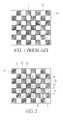
- FIG. 1illustrates a diagram of a calibrating plate 10 for a robot arm according to a prior art.
- the calibrating platehas a chessboard having interchanging black squares 11 and white squares 12 .
- a visual system of the robot armis used.
- the visual systemcomprises an eye in hand camera configured to guide the robot arm when grabbing an object and an eye to hand camera configured to monitor a working environment of the robot arm.
- the eye in hand camerais brought close to the standard calibration plate 10 by moving the robot arm to capture an image of the standard calibration plate 10 . According to the captured image, the position of the robot arm relative to the standard calibration plate is calculated to complete the calibration of the robot arm.
- U.S. Pat. No. 6,985,175is configured to use two cameras to capture images of the status of the standard calibration plate and perform comparison to calibrate the two cameras.
- CN102927908is configured to use a laser apparatus to project light strip for performing alignment of standard calibration plate.
- the camera fixed on the robot armis used to capture image of the light strip.
- the laser apparatusis moved to another position and another image of the light strip projected by the laser apparatus at another angular position is captured.
- the intersection of the two light strips from two different angular positionsis used to calibrate position of the robot in a three-dimensional space.
- the standard calibration plate of the prior arthas a fixed number of black and white squares in the chessboard pattern. If the robot arm is set on a limited space and the distance between the robot arm and the standard calibration plate is fixed, the visual system arranged on the robot arm is not able to capture the entire image of the standard calibration plate. It would not be possible to determine the orientation and position of the visual system using the partial image of the standard calibration plate. Thus, it is hard to determine the correct position of the visual system relative to the standard calibration plate to perform calibration. Therefore, existing method of calibrating robot arm still has problems that need to be solved.
- An objective of the present inventionis to provide a robot calibration apparatus for a robot arm.
- a plurality of encodingsare arranged on an encoded calibrating plate of the robot calibration apparatus. Each encoding corresponds to a predetermined coordinate.
- a visual system of the robot calibration apparatusis configured to capture an image of an encoding of a part of the encoded calibrating plate to quickly perform position calibration of the visual system to increase the flexibility of space used by the robot arm.
- Another objective of the present inventionis to provide a method for calibrating a robot arm.
- a visual system of the robot calibration apparatusis focused on an encoded calibrating plate and captures an image of the encoded calibrating plate. Coordinates of an encoding is calculated and positioning of the visual system is performed to determine moving error of the robot arm used for calibrating movement of the robot arm.
- a further objective of the present inventionis to provide another method for calibrating a robot arm.
- a visual system of the robot calibration apparatusis focused on several positions of an encoded calibrating plate and captures images of the encoded calibrating plate.
- An average of moving errors of the robot armis calculated to increase the accuracy of calibration of movement of the robot arm.
- An additional objective of the present inventionis to provide a further method for calibrating a robot arm. Positioning of an eye in hand camera and positioning of an eye to hand camera of the robot arm are separately performed using an encoded calibrating plate to calibrate the movement of the robot arm.
- a robot calibration apparatus of the present inventionincludes a robot arm having a fixed end fixed on a base and a movable end where an eye in hand camera of a visual system is fixed on.
- An encoded calibrating plateis fixed on the working environment of the robot arm using a support frame and has fixed coordinates relative to the robot arm.
- the encoded calibrating platehas a chessboard pattern. Each square of the chessboard pattern has an encoding to indicate an orientation of the encoded calibrating plate or a position on the encoded calibrating plate.
- a controlleris configured to receive images from the visual system and control a movement of the eye in hand camera fixed on the movable end of the robot arm for capturing an image of an encoding of the encoded calibrating plate.
- the imageis used to calibrate a positioning error between coordinates of the eye in hand camera with respect to the fixed end of the robot arm.
- the visual systemfurther comprises an eye to hand camera.
- the eye to hand camerais fixed outside the robot arm.
- the eye to hand camerahas fixed coordinates relative to the robot arm.
- the controllermoves the movable end of the robot arm to positions of the plurality of encodings of the encoded calibrating plate to capture images that are used to correct a positioning error of coordinates of the eye to hand camera with respect to the fixed end of the robot arm.
- the squares of the chessboard pattern of the encoded calibrating plateare alternating black squares and white squares.
- Each of The black squareshas an icon positioned near a corner as an orientation encodings for indicating that an origin of the encoded calibration plate is close to a corresponding corner of the encoded calibration plate.
- the white squareshas encoding icons including hollow icons and solid icons arranged and grouped together to form a coordinates encoding for indicating the positions of the white squares on the encoded calibration plate relative to an origin of the encoded calibration plate.
- the encoding circles in the white squareare arranged in two columns. A first column of the two columns represents an X-coordinate of the encoded calibration plate.
- a second column of the two columnsrepresents a Y-coordinate of the encoded calibration plate.
- a method of calibrating a robot armincludes positioning a visual system of the robot arm to have at least a part of an encoded calibrating plate within a photographic range of the visual system, focusing the visual system to capture an image of the encoded calibrating plate, determining position of the visual system according to coordinates indicated in a coordinates encoding in the image of the encoded calibration plate and a focus of the eye in hand camera, comparing the coordinates of the eye in hand camera before and after positioning to calculate a moving error, and calibrating the position of the eye in hand camera.
- the visual system of the method of calibrating a robot armcomprises an eye to hand camera and eye in hand camera. calibrations of the positioning of the eye to hand camera and eye in hand camera are implemented separately. After calibrating the position of the eye in hand camera, when the number of calibration times is less than a predetermined number, the robot arm is moved to a different position and calibration operation is repeated. When the number of calibration times is equal to the predetermined number, an average of the moving errors determined during calibration operations is calculated.
- FIG. 1illustrates a diagram of a calibrating plate for a robot arm according to a prior art.
- FIG. 2illustrates a diagram of an encoded calibration plate of a robot calibration apparatus according to an embodiment of the present invention.
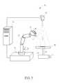
- FIG. 3illustrates a diagram of a robot calibration apparatus according to an embodiment of the present invention.
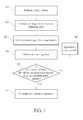
- FIG. 4illustrates a flowchart of a method of calibrating a robot arm in FIG. 3 .
- FIG. 5illustrates a diagram of a robot calibration apparatus according to another embodiment of the present invention.
- FIG. 6illustrates a flowchart of a method of calibrating a visual system of a robot calibration apparatus in FIG. 5 .
- FIG. 2illustrates a diagram of an encoded calibration plate 20 of a robot calibration apparatus according to an embodiment of the present invention.
- the encoded calibration plate 20may have a chessboard pattern.
- the chessboard patternmay comprise of interchanging black squares 21 and white squares 22 .
- the black squares 21may have orientation encodings for indicating an orientation of the encoded calibration plate 20 and the white squares 22 may have coordinates encodings for indicating positions on the encoded calibration plate 20 .
- An orientation encoding of a black square 21may include an icon 23 positioned near a corner of the black square 21 to indicate that an origin O of the encoded calibration plate 20 may be close to a corresponding corner of the encoded calibration plate 20 .
- a coordinates encoding in a white square 22may comprise encoding icons arranged in a matrix to indicate a position of the white square 22 relative to the origin O of the encoded calibration plate 20 .
- the encoding icons in a white square 22may comprise of only solid icons 25 , or a combination of both hollow icons 24 and solid icons 25 arranged in two columns. As shown in FIG. 2 , a first column on one side of the white square 22 may be used to represent an X-coordinate of the encoded calibration plate 20 and a second column on another side of the white square 22 may be used to represent a Y-coordinate of the encoded calibration plate 20 .
- Each of the X-coordinate and Y-coordinatemay be represented by a combination of an encoding icon in row A, an encoding icon in row B, and an encoding icon in row C.
- Each encoding iconmay represent a binary bit.
- Encoding icons from row Amay have a binary weight of 2 0
- encoding icons from row Bmay have a binary weight of 2 1
- encoding icons from row Cmay have a binary weight of 2 2 .
- the hollow icons 24may represent a bit 0 value and the solid icons 25 may represent a bit 1 value.
- the calculated coordinates of the white square 22 of the exampleare (6,1). Therefore, the coordinates of the white square 22 with respect to the origin O of the encoded calibration plate 20 may be calculated using the hollow icons 24 and the solid icons 25 in the white square 22 .
- FIG. 3illustrates a diagram of a robot calibration apparatus 30 according to an embodiment of the present invention.
- the robot calibration apparatus 30may comprise a visual system, a robot arm 31 , a controller 32 and an encoded calibrating plate 20 .
- the visual systemmay comprise an eye in hand camera 34 arranged on the robot arm 31 .
- the robot arm 31may have a fixed end fixed on a base 35 . The position on the base 35 where the fixed end is fixed may be taken as a reference point M.
- the robot arm 31may also have a movable end where the eye in hand camera 34 is fixed. Before calibration operation, initial coordinates of the eye in hand camera 34 with respect to the reference point M may be set.
- a support frame 36may be used to fix the encoded calibrating plate 20 within a working environment of the eye in hand camera 34 or the robot arm 31 .
- the position where the support frame 36 is fixedmay be taken as a reference point N.
- the position of the origin O in the encoded calibrating plate 20 with respect to the reference point Nmay be known.
- the position of the white squares 22 indicated by the coordinates encodings with respect to the reference point Nmay also be known.
- the relative coordinates between the reference point M and the reference point Nis fixed.
- the reference point Nmay have fixed coordinates correlation with the reference point M.
- the fixed coordinates correlation between the reference point N and reference point Nmay be used to determine the correct coordinates of the eye in hand camera 34 with respect to the reference point M.
- the controller 32may be used to move the robot arm 31 to bring the eye in hand camera 34 towards the encoded calibrating plate 20 .
- a focus F of the eye in hand camera 34may be adjusted to capture a clear image 26 of the encoded calibrating plate 20 .
- the distance between the eye in hand camera 34 and the encoded calibrating plate 20may be determined.
- the image 26may include a white square 22 having a coordinates encoding and at least one part of a black square having at least one part of an orientation encoding.
- At least one part of the icon 23may be included in the at least one part of a black square captured in the image 26 .
- the at least one part of the icon 23may be used to indicate an orientation of the encoded calibrating plate 20 and the coordinates encoding in the white square 22 may be used to determine the coordinates of the white square 22 with respect to reference point N.
- the position of the eye in hand camera 34 with respect to reference point Nmay be determined.
- the correct coordinates of the eye in hand camera 34 with respect to the reference point Mmay be determined using the fixed coordinates correlation between the reference point M and the reference point N.
- a moving error of the robot arm 31may be determined by comparing the coordinates of eye in hand camera 34 with respect to the reference point M recorded in a memory of the controller 32 before calibration and the coordinates of eye in hand camera 34 with respect to the reference point M after calibration.
- the moving errormay be stored in the memory of the controller 32 .
- the moving error of the robot arm 31 with respect to different positionmay vary due to the components and weight of the robot arm 31 . Therefore, a plurality of moving errors may be determined by having the robot arm 31 controlled by the controller 32 move the eye in hand camera 34 through several different positions in the encoded calibrating plate 20 .
- the eye in hand camera 34may capture images of several different positions of the encoded calibrating plate 20 and perform calibration operation at the several different positions.
- the moving errors determined through the calibration operationsmay be saved in the memory of the controller 32 and an average of the moving errors may be determined. The average of the moving errors may be used to increase accuracy of the movement of the robot arm 31 .
- FIG. 4illustrates a flowchart of a method of calibrating a robot arm in FIG. 3 .
- the steps of the method of calibrating the robot armmay include but is not limited to the following steps:
- Step R 1position a visual system of the robot arm to have at least apart of an encoded calibrating plate within a photographic range of the visual system;
- Step R 2adjust a focus of the visual system and capture an image of the encoded calibrating plate
- Step R 3perform positioning of the visual system according to coordinates determined from a coordinates encoding of the image of the encoded calibrating plate, an orientation encoding of the image of the encoded calibrating plate, and a focus of the visual system;
- Step R 4compare coordinates of the position of the visual system camera before calibration and the position of the visual system camera after calibration to determine a moving error
- Step R 5determine if the number of times the calibration operation performed is equal to a predetermined number; If so, go to step R 7 ; if not, go to step R 6 ;
- Step R 6reposition the visual system to have another part of the encoded calibrating plate within a photographic range of the visual system; go to step R 2 ; and
- Step R 7adapt to different moving errors of the robot arm to complete the calibration operation.
- the robot calibration apparatusmay be configured to use the coordinates encoding comprising of hollow icons and solid icons arranged in the white squares of the image captured by the visual system to determine coordinates of the visual system. Therefore, the robot calibration apparatus need not capture the whole area of the encoded calibrating plate to determine the position of the visual system. Thus, flexibility of space needed to be used by the robot arm during calibration operation may be achieved. Also, the robot calibration apparatus may perform the calibration operation a plurality of times to determine varying moving errors due to the components and weight of the robot arm to increase the accuracy of the movement of the robot arm.
- FIG. 5illustrates a diagram of a robot calibration apparatus 30 according to another embodiment of the present invention.
- the visual system of the robot calibration apparatus 30may further comprise an eye to hand camera 40 .
- initial coordinates of the eye to hand camera 34 with respect to the reference point Mmay be set.
- the eye to hand camera 40may be configured to capture an image of a working environment of the robot arm 31 and guide the movable end 33 of the robot arm 31 to perform a task.
- the eye in hand camera 34may then be used to capture an image of a target position of the task to allow the controller 32 to determine position where the task is to be performed.
- the task of the robot arm 31may be to grab an object.
- the controller 32may move the movable end 33 of the robot arm 31 with respect to the reference point M to capture an image of the object and set the clamp 37 at the movable end 33 to perform the grabbing of the object.
- the position of the eye in hand camera 34 and the eye to hand camera 40may be calibrated separately. The calibration of the eye in hand camera 34 and the eye to hand camera 40 need not be performed in a specific sequence.
- the calibration of the eye in hand camera 34may be performed first. After the position of the eye in hand camera 34 has been calibrated, the eye to hand camera 40 may be calibrated next. Before calibrating the position of the eye to hand camera 40 , the movable end 33 of the robot arm 31 may be moved away from the encoded calibration plate 20 .
- the support frame 36may be used to fix the encoded calibrating plate 20 within a photographic range of the eye to hand camera 40 .
- the position of the support framemay be taken as the reference point N.
- the position of the origin O in the encoded calibrating plate 20 with respect to the reference point Nmay be known.
- the position of the white squares 22 indicated by the coordinates encoding with respect to the reference point Nmay also be known.
- the distance between the reference point M and the reference point Nmay be fixed.
- the reference point M and the reference point Nmay have fixed coordinates correlation.
- the fixed coordinates correlation between the reference point N and reference point Mmay be used to determine the correct coordinates of the eye in hand camera 34 with respect to the reference point M.
- the eye to hand camera 40may be focused to capture a clear image of the encoded calibrating plate 20 . If the distance between the eye to hand camera 40 and the encoded calibrating plate 20 is high enough, the eye to hand camera 40 may capture an image of whole of the encoded calibrating plate 20 . If the distance between the eye to hand camera 40 and the encoded calibrating plate 20 is not high enough, the eye to hand camera 40 may only capture an image 26 of a part of the encoded calibrating plate 20 .
- the coordinates with respect to the reference point N of the eye to hand camera 40may be determined according to the focus F of the eye to hand camera 40 and the coordinates encoding captured in the image 26 .
- the correct coordinates of the eye to hand camera 40 with respect to the reference point Mmay be determined to complete positioning of the eye to hand camera 40 .
- a positioning error of the eye to hand camera 40 with respect to the reference point Mmay be determined by comparing the coordinates of eye to hand camera 40 with respect to the reference point M stored in the memory before calibration and the coordinates of eye to hand camera 40 with respect to the reference point M after calibration.
- the robot arm 31may be able to perform movement more accurately after calibrating the positioning errors of the eye in hand camera 31 and the eye to hand camera 40 .
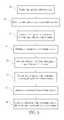
- FIG. 6illustrates a flowchart of a method of calibrating a visual system of a robot calibration apparatus in FIG. 5 .
- the steps of the method of calibrating the visual systemmay include but is not limited to the following steps:
- Step S 1position the encoded calibrating plate to be within a working environment of a robot arm, an eye in hand camera, and an eye to hand camera;
- Step S 2move the robot arm to the encoded calibrating plate
- Step S 3capture an image of the coordinates encoding using the eye in hand camera
- Step S 4determine coordinates of eye in hand camera according to the image of the coordinates encoding captured by the eye in hand camera;
- Step S 5move the robot arm out of the photographic range of the eye to hand camera
- Step S 6capture another image of the coordinates encoding using the eye to hand camera
- Step S 7determine coordinates of eye to hand camera according to the another image of the coordinates encoding captured by the eye to hand camera;
- Step S 8complete calibration of the positioning error of the eye in hand camera and eye to hand camera.
- positioning of eye in hand cameramay be performed first.
- the positioning of eye in hand cameramay comprise receiving coordinates of the eye in hand camera fixed on a moveable end of the robot arm relative to coordinates of a fixed end of the robot arm, capturing a first image of an encoded calibrating plate by the eye in hand camera, determining coordinates of the eye in hand camera indicated by a coordinates encoding in the first image, and an orientation indicated by an orientation encoding in the first image, determining correct coordinates of the eye in hand camera relative to the fixed end of the robot arm according to at least the coordinates indicated by the coordinates encoding in the first image, the orientation indicated by the orientation encoding in the first image, a focus of the eye in hand camera, and determining a moving error of the eye in hand camera according to the received coordinates of the eye in hand camera and the correct coordinates of the eye in hand camera.
- positioning of eye to hand cameramay be performed by having a second image of an encoded calibrating plate captured by an eye to hand camera, and having coordinates of the eye to hand camera relative to the fixed end of the robot arm determined according to at least the coordinates indicated by the coordinates encoding in the second image, the orientation indicated by the orientation encoding in the second image, and a focus of the eye to hand camera.
- a robot calibration apparatus and method for calibrating a robot arm of the present inventionmay use an encoded calibration plate to separately calibrate the positioning of an eye in hand camera and an eye to hand camera of the robot arm and to calibrate a moving error of the robot arm.
Landscapes
- Engineering & Computer Science (AREA)
- Robotics (AREA)
- Mechanical Engineering (AREA)
- Manipulator (AREA)
Abstract
Description
X=A*20+B*21+C*22
Y=A*20+B*21+C*22
X=A*20+B*21+C*22
Y=A*20+B*21+C*22
X=0*20+1*21+1*22=6
Y=1*20+0*21+0*22=1
Claims (13)
X=A*20+B*21+C*22
Y=A*20+B*21+C*22
Priority Applications (1)
| Application Number | Priority Date | Filing Date | Title |
|---|---|---|---|
| US14/514,408US9193073B1 (en) | 2014-10-15 | 2014-10-15 | Robot calibration apparatus for calibrating a robot arm |
Applications Claiming Priority (1)
| Application Number | Priority Date | Filing Date | Title |
|---|---|---|---|
| US14/514,408US9193073B1 (en) | 2014-10-15 | 2014-10-15 | Robot calibration apparatus for calibrating a robot arm |
Publications (1)
| Publication Number | Publication Date |
|---|---|
| US9193073B1true US9193073B1 (en) | 2015-11-24 |
Family
ID=54542723
Family Applications (1)
| Application Number | Title | Priority Date | Filing Date |
|---|---|---|---|
| US14/514,408ActiveUS9193073B1 (en) | 2014-10-15 | 2014-10-15 | Robot calibration apparatus for calibrating a robot arm |
Country Status (1)
| Country | Link |
|---|---|
| US (1) | US9193073B1 (en) |
Cited By (26)
| Publication number | Priority date | Publication date | Assignee | Title |
|---|---|---|---|---|
| US20180181793A1 (en)* | 2016-12-22 | 2018-06-28 | Toshiba Tec Kabushiki Kaisha | Image processing apparatus and image processing method |
| WO2018128355A1 (en)* | 2017-01-04 | 2018-07-12 | Samsung Electronics Co., Ltd. | Robot and electronic device for performing hand-eye calibration |
| US20180243911A1 (en)* | 2014-11-21 | 2018-08-30 | Seiko Epson Corporation | Robot and robot system |
| CN109176487A (en)* | 2018-09-28 | 2019-01-11 | 哈尔滨工业大学(深圳) | A kind of cooperating joint section scaling method, system, equipment, storage medium |
| CN109382821A (en)* | 2017-08-09 | 2019-02-26 | 欧姆龙株式会社 | Calibration method, calibration system and program |
| US10232511B2 (en)* | 2016-05-12 | 2019-03-19 | Carl Zeiss Automated Inspection GmbH | Method for calibrating a measuring apparatus for measuring body parts and other workpieces, and measuring apparatus suitable for carrying out the method |
| CN109531604A (en)* | 2017-09-22 | 2019-03-29 | 发那科株式会社 | Robot controller, measuring system and the calibration method calibrated |
| CN109648605A (en)* | 2017-10-11 | 2019-04-19 | 精工爱普生株式会社 | Robot system |
| DE102017217142B4 (en) | 2016-09-28 | 2019-10-02 | Cognex Corporation | Simultaneous kinematic and hand-eye calibration |
| CN110788863A (en)* | 2019-11-22 | 2020-02-14 | 上海原能细胞生物低温设备有限公司 | Machine vision calibration method and mechanical arm positioning and grabbing method |
| US10611022B2 (en)* | 2016-11-29 | 2020-04-07 | Rolls-Royce Plc | Methods, apparatus, computer programs and non-transitory computer readable storage mediums for controlling a hyper redundant manipulator |
| WO2020121396A1 (en)* | 2018-12-11 | 2020-06-18 | 株式会社Fuji | Robot calibration system and robot calibration method |
| CN111660290A (en)* | 2019-03-05 | 2020-09-15 | 波音公司 | Automatic calibration for robotic optical sensors |
| CN111899629A (en)* | 2020-08-04 | 2020-11-06 | 菲尼克斯(南京)智能制造技术工程有限公司 | Flexible robot teaching system and method |
| CN113459108A (en)* | 2021-09-02 | 2021-10-01 | 杭州灵西机器人智能科技有限公司 | Hand-eye calibration method, system, device and medium based on interpolation compensation |
| CN113865622A (en)* | 2021-12-06 | 2021-12-31 | 北京诺亦腾科技有限公司 | Precision detection method, device, equipment and medium for optical positioning system |
| US11241795B2 (en)* | 2018-09-21 | 2022-02-08 | Beijing Jingdong Shangke Information Technology Co., Ltd. | Soft package, robot system for processing the same, and method thereof |
| US11267129B2 (en)* | 2018-11-30 | 2022-03-08 | Metal Industries Research & Development Centre | Automatic positioning method and automatic control device |
| US11290395B1 (en) | 2017-05-18 | 2022-03-29 | Juniper Networks, Inc. | Emulating output queued behavior in a virtual output queue switch |
| CN114305705A (en)* | 2022-03-15 | 2022-04-12 | 珠海维尔康生物科技有限公司 | Automatic correcting device and method for position of surgical robot |
| CN114872038A (en)* | 2022-04-13 | 2022-08-09 | 欣旺达电子股份有限公司 | Micro-needle buckling vision self-calibration system and calibration method thereof |
| US11433541B2 (en)* | 2019-12-18 | 2022-09-06 | Industrial Technology Research Institute | Automated calibration system and method for a workpiece coordinate frame of a robot |
| US11919177B1 (en)* | 2023-04-03 | 2024-03-05 | Guangdong University Of Technology | Tracking measurement method, apparatus and device for pose of tail end of manipulator |
| WO2024193136A1 (en)* | 2023-03-21 | 2024-09-26 | 深圳市越疆科技股份有限公司 | Calibration board, hand-eye calibration data acquisition method and hand-eye calibration method for robot arm |
| CN119963659A (en)* | 2025-04-10 | 2025-05-09 | 无锡黎曼机器人科技有限公司 | Calibration board and calibration method for camera parameter calibration |
| US12420424B2 (en) | 2020-04-14 | 2025-09-23 | Fanuc Corporation | Coordinate system setting system and position/orientation measurement system |
Citations (4)
| Publication number | Priority date | Publication date | Assignee | Title |
|---|---|---|---|---|
| US4398720A (en)* | 1981-01-05 | 1983-08-16 | California R & D Center | Robot computer chess game |
| US5951475A (en)* | 1997-09-25 | 1999-09-14 | International Business Machines Corporation | Methods and apparatus for registering CT-scan data to multiple fluoroscopic images |
| US20030144765A1 (en)* | 2002-01-31 | 2003-07-31 | Babak Habibi | Method and apparatus for single camera 3D vision guided robotics |
| US20040172164A1 (en)* | 2002-01-31 | 2004-09-02 | Babak Habibi | Method and apparatus for single image 3D vision guided robotics |
- 2014
- 2014-10-15USUS14/514,408patent/US9193073B1/enactiveActive
Patent Citations (4)
| Publication number | Priority date | Publication date | Assignee | Title |
|---|---|---|---|---|
| US4398720A (en)* | 1981-01-05 | 1983-08-16 | California R & D Center | Robot computer chess game |
| US5951475A (en)* | 1997-09-25 | 1999-09-14 | International Business Machines Corporation | Methods and apparatus for registering CT-scan data to multiple fluoroscopic images |
| US20030144765A1 (en)* | 2002-01-31 | 2003-07-31 | Babak Habibi | Method and apparatus for single camera 3D vision guided robotics |
| US20040172164A1 (en)* | 2002-01-31 | 2004-09-02 | Babak Habibi | Method and apparatus for single image 3D vision guided robotics |
Cited By (42)
| Publication number | Priority date | Publication date | Assignee | Title |
|---|---|---|---|---|
| US20180243911A1 (en)* | 2014-11-21 | 2018-08-30 | Seiko Epson Corporation | Robot and robot system |
| US10525597B2 (en)* | 2014-11-21 | 2020-01-07 | Seiko Epson Corporation | Robot and robot system |
| US10232511B2 (en)* | 2016-05-12 | 2019-03-19 | Carl Zeiss Automated Inspection GmbH | Method for calibrating a measuring apparatus for measuring body parts and other workpieces, and measuring apparatus suitable for carrying out the method |
| US10864639B2 (en) | 2016-09-28 | 2020-12-15 | Cognex Corporation | Simultaneous kinematic and hand-eye calibration |
| DE102017217142B4 (en) | 2016-09-28 | 2019-10-02 | Cognex Corporation | Simultaneous kinematic and hand-eye calibration |
| US10611022B2 (en)* | 2016-11-29 | 2020-04-07 | Rolls-Royce Plc | Methods, apparatus, computer programs and non-transitory computer readable storage mediums for controlling a hyper redundant manipulator |
| US20180181793A1 (en)* | 2016-12-22 | 2018-06-28 | Toshiba Tec Kabushiki Kaisha | Image processing apparatus and image processing method |
| US10970521B2 (en) | 2016-12-22 | 2021-04-06 | Toshiba Tec Kabushiki Kaisha | Image processing apparatus and image processing method |
| WO2018128355A1 (en)* | 2017-01-04 | 2018-07-12 | Samsung Electronics Co., Ltd. | Robot and electronic device for performing hand-eye calibration |
| US10780585B2 (en) | 2017-01-04 | 2020-09-22 | Samsung Electronics Co., Ltd. | Robot and electronic device for performing hand-eye calibration |
| US11290395B1 (en) | 2017-05-18 | 2022-03-29 | Juniper Networks, Inc. | Emulating output queued behavior in a virtual output queue switch |
| JP2019030943A (en)* | 2017-08-09 | 2019-02-28 | オムロン株式会社 | Calibration method, calibration system and program |
| US10940591B2 (en) | 2017-08-09 | 2021-03-09 | Omron Corporation | Calibration method, calibration system, and program |
| EP3446838A1 (en)* | 2017-08-09 | 2019-02-27 | Omron Corporation | Calibration method, calibration system, and program |
| CN109382821A (en)* | 2017-08-09 | 2019-02-26 | 欧姆龙株式会社 | Calibration method, calibration system and program |
| US10569418B2 (en)* | 2017-09-22 | 2020-02-25 | Fanuc Corporation | Robot controller for executing calibration, measurement system and calibration method |
| CN109531604A (en)* | 2017-09-22 | 2019-03-29 | 发那科株式会社 | Robot controller, measuring system and the calibration method calibrated |
| CN109648605B (en)* | 2017-10-11 | 2023-03-21 | 精工爱普生株式会社 | Robot system |
| US11090810B2 (en) | 2017-10-11 | 2021-08-17 | Seiko Epson Corporation | Robot system |
| EP3470182A3 (en)* | 2017-10-11 | 2019-05-15 | Seiko Epson Corporation | Robot system |
| JP2019069493A (en)* | 2017-10-11 | 2019-05-09 | セイコーエプソン株式会社 | Robot system |
| CN109648605A (en)* | 2017-10-11 | 2019-04-19 | 精工爱普生株式会社 | Robot system |
| US11241795B2 (en)* | 2018-09-21 | 2022-02-08 | Beijing Jingdong Shangke Information Technology Co., Ltd. | Soft package, robot system for processing the same, and method thereof |
| CN109176487A (en)* | 2018-09-28 | 2019-01-11 | 哈尔滨工业大学(深圳) | A kind of cooperating joint section scaling method, system, equipment, storage medium |
| US11267129B2 (en)* | 2018-11-30 | 2022-03-08 | Metal Industries Research & Development Centre | Automatic positioning method and automatic control device |
| WO2020121396A1 (en)* | 2018-12-11 | 2020-06-18 | 株式会社Fuji | Robot calibration system and robot calibration method |
| JPWO2020121396A1 (en)* | 2018-12-11 | 2021-09-02 | 株式会社Fuji | Robot calibration system and robot calibration method |
| CN111660290A (en)* | 2019-03-05 | 2020-09-15 | 波音公司 | Automatic calibration for robotic optical sensors |
| CN110788863A (en)* | 2019-11-22 | 2020-02-14 | 上海原能细胞生物低温设备有限公司 | Machine vision calibration method and mechanical arm positioning and grabbing method |
| US11433541B2 (en)* | 2019-12-18 | 2022-09-06 | Industrial Technology Research Institute | Automated calibration system and method for a workpiece coordinate frame of a robot |
| US12420424B2 (en) | 2020-04-14 | 2025-09-23 | Fanuc Corporation | Coordinate system setting system and position/orientation measurement system |
| CN111899629A (en)* | 2020-08-04 | 2020-11-06 | 菲尼克斯(南京)智能制造技术工程有限公司 | Flexible robot teaching system and method |
| CN113459108A (en)* | 2021-09-02 | 2021-10-01 | 杭州灵西机器人智能科技有限公司 | Hand-eye calibration method, system, device and medium based on interpolation compensation |
| CN113459108B (en)* | 2021-09-02 | 2021-11-12 | 杭州灵西机器人智能科技有限公司 | Hand-eye calibration method, system, device and medium based on interpolation compensation |
| CN113865622A (en)* | 2021-12-06 | 2021-12-31 | 北京诺亦腾科技有限公司 | Precision detection method, device, equipment and medium for optical positioning system |
| CN114305705A (en)* | 2022-03-15 | 2022-04-12 | 珠海维尔康生物科技有限公司 | Automatic correcting device and method for position of surgical robot |
| CN114872038A (en)* | 2022-04-13 | 2022-08-09 | 欣旺达电子股份有限公司 | Micro-needle buckling vision self-calibration system and calibration method thereof |
| CN114872038B (en)* | 2022-04-13 | 2023-12-01 | 欣旺达电子股份有限公司 | Micro-needle buckling vision self-calibration system and calibration method thereof |
| WO2024193136A1 (en)* | 2023-03-21 | 2024-09-26 | 深圳市越疆科技股份有限公司 | Calibration board, hand-eye calibration data acquisition method and hand-eye calibration method for robot arm |
| US11919177B1 (en)* | 2023-04-03 | 2024-03-05 | Guangdong University Of Technology | Tracking measurement method, apparatus and device for pose of tail end of manipulator |
| CN119963659A (en)* | 2025-04-10 | 2025-05-09 | 无锡黎曼机器人科技有限公司 | Calibration board and calibration method for camera parameter calibration |
| CN119963659B (en)* | 2025-04-10 | 2025-07-15 | 无锡黎曼机器人科技有限公司 | Calibration method for camera parameter calibration |
Similar Documents
| Publication | Publication Date | Title |
|---|---|---|
| US9193073B1 (en) | Robot calibration apparatus for calibrating a robot arm | |
| US10112301B2 (en) | Automatic calibration method for robot systems using a vision sensor | |
| CN114174006B (en) | Robot hand-eye calibration method, device, computing equipment, medium and product | |
| CN107598977B (en) | Method and system for realizing automatic robot teaching by using vision and laser range finder | |
| US11087457B1 (en) | Digital projection system and associated method | |
| JP5815761B2 (en) | Visual sensor data creation system and detection simulation system | |
| KR102276259B1 (en) | Calibration and operation of vision-based manipulation systems | |
| TWI670153B (en) | Robot and robot system | |
| JP5850962B2 (en) | Robot system using visual feedback | |
| US10661442B2 (en) | Calibration article for a 3D vision robotic system | |
| US10295335B2 (en) | Shape measurement apparatus and shape measurement method | |
| JP2008021092A (en) | Simulation apparatus of robot system | |
| KR102314092B1 (en) | Calibration apparatus and the method for robot | |
| JP7191309B2 (en) | Automatic Guidance, Positioning and Real-time Correction Method for Laser Projection Marking Using Camera | |
| CN111376254B (en) | Plane ranging method and system and plane adjusting method and system for mechanical arm | |
| CN117359135B (en) | Galvanometer correction method, galvanometer correction device, computer apparatus, storage medium, and program product | |
| CN105279775A (en) | Calibration device and method for robotic arm | |
| JP7414850B2 (en) | robot system | |
| US8872911B1 (en) | Line scan calibration method and apparatus | |
| US20130342659A1 (en) | Three-dimensional position/attitude recognition apparatus, three-dimensional position/attitude recognition method, and three-dimensional position/attitude recognition program | |
| KR102147777B1 (en) | The robot auto teaching system using image and laser hybrid signal, and the method thereof | |
| KR101735325B1 (en) | Apparatus for registration of cloud points | |
| KR102463560B1 (en) | Calibration device of laser vision system | |
| US12109714B1 (en) | Kinematics parameter calibration method and system of multi-axis motion platform | |
| JP6565367B2 (en) | Position correction system |
Legal Events
| Date | Code | Title | Description |
|---|---|---|---|
| AS | Assignment | Owner name:QUANTA STORAGE INC., TAIWAN Free format text:ASSIGNMENT OF ASSIGNORS INTEREST;ASSIGNORS:HUANG, CHUNG-HSIEN;SHIA, SHAO-JI;WU, JEN-CHEN;REEL/FRAME:033948/0881 Effective date:20141008 | |
| AS | Assignment | Owner name:QUANTA STORAGE INC., TAIWAN Free format text:CHANGE OF THE ADDRESS OF THE ASSIGNEE;ASSIGNOR:QUANTA STORAGE INC.;REEL/FRAME:036718/0469 Effective date:20150925 | |
| STCF | Information on status: patent grant | Free format text:PATENTED CASE | |
| MAFP | Maintenance fee payment | Free format text:PAYMENT OF MAINTENANCE FEE, 4TH YR, SMALL ENTITY (ORIGINAL EVENT CODE: M2551); ENTITY STATUS OF PATENT OWNER: SMALL ENTITY Year of fee payment:4 | |
| AS | Assignment | Owner name:TECHMAN ROBOT INC., TAIWAN Free format text:ASSIGNMENT OF ASSIGNORS INTEREST;ASSIGNOR:QUANTA STORAGE INC.;REEL/FRAME:054248/0050 Effective date:20201026 | |
| MAFP | Maintenance fee payment | Free format text:PAYMENT OF MAINTENANCE FEE, 8TH YR, SMALL ENTITY (ORIGINAL EVENT CODE: M2552); ENTITY STATUS OF PATENT OWNER: SMALL ENTITY Year of fee payment:8 |