US9192705B2 - Percutaneous cable with redundant conductors for implantable blood pump - Google Patents
Percutaneous cable with redundant conductors for implantable blood pumpDownload PDFInfo
- Publication number
- US9192705B2 US9192705B2US13/849,704US201313849704AUS9192705B2US 9192705 B2US9192705 B2US 9192705B2US 201313849704 AUS201313849704 AUS 201313849704AUS 9192705 B2US9192705 B2US 9192705B2
- Authority
- US
- United States
- Prior art keywords
- conductors
- cable
- conductor
- pair
- redundant
- Prior art date
- Legal status (The legal status is an assumption and is not a legal conclusion. Google has not performed a legal analysis and makes no representation as to the accuracy of the status listed.)
- Expired - Fee Related, expires
Links
- 239000004020conductorSubstances0.000titleclaimsabstractdescription96
- 239000008280bloodSubstances0.000titleclaimsabstractdescription9
- 210000004369bloodAnatomy0.000titleclaimsabstractdescription9
- 210000005240left ventricleAnatomy0.000claimsabstractdescription5
- 238000004804windingMethods0.000claimsabstractdescription5
- 230000017531blood circulationEffects0.000description2
- 230000007774longtermEffects0.000description2
- 238000000034methodMethods0.000description2
- 238000005086pumpingMethods0.000description2
- 230000002861ventricularEffects0.000description2
- 208000024172Cardiovascular diseaseDiseases0.000description1
- 210000000709aortaAnatomy0.000description1
- 239000000560biocompatible materialSubstances0.000description1
- 230000000747cardiac effectEffects0.000description1
- 230000004087circulationEffects0.000description1
- 230000003750conditioning effectEffects0.000description1
- 238000005336crackingMethods0.000description1
- 230000003111delayed effectEffects0.000description1
- 238000001514detection methodMethods0.000description1
- 238000010586diagramMethods0.000description1
- 239000000835fiberSubstances0.000description1
- 238000002513implantationMethods0.000description1
- 239000000463materialSubstances0.000description1
- 238000012544monitoring processMethods0.000description1
- 230000002028prematureEffects0.000description1
- 230000001360synchronised effectEffects0.000description1
Images


Classifications
- A—HUMAN NECESSITIES
- A61—MEDICAL OR VETERINARY SCIENCE; HYGIENE
- A61M—DEVICES FOR INTRODUCING MEDIA INTO, OR ONTO, THE BODY; DEVICES FOR TRANSDUCING BODY MEDIA OR FOR TAKING MEDIA FROM THE BODY; DEVICES FOR PRODUCING OR ENDING SLEEP OR STUPOR
- A61M60/00—Blood pumps; Devices for mechanical circulatory actuation; Balloon pumps for circulatory assistance
- A61M60/10—Location thereof with respect to the patient's body
- A61M60/122—Implantable pumps or pumping devices, i.e. the blood being pumped inside the patient's body
- A61M60/126—Implantable pumps or pumping devices, i.e. the blood being pumped inside the patient's body implantable via, into, inside, in line, branching on, or around a blood vessel
- A61M60/148—Implantable pumps or pumping devices, i.e. the blood being pumped inside the patient's body implantable via, into, inside, in line, branching on, or around a blood vessel in line with a blood vessel using resection or like techniques, e.g. permanent endovascular heart assist devices
- A61M1/122—
- A—HUMAN NECESSITIES
- A61—MEDICAL OR VETERINARY SCIENCE; HYGIENE
- A61M—DEVICES FOR INTRODUCING MEDIA INTO, OR ONTO, THE BODY; DEVICES FOR TRANSDUCING BODY MEDIA OR FOR TAKING MEDIA FROM THE BODY; DEVICES FOR PRODUCING OR ENDING SLEEP OR STUPOR
- A61M60/00—Blood pumps; Devices for mechanical circulatory actuation; Balloon pumps for circulatory assistance
- A61M60/80—Constructional details other than related to driving
- A61M60/855—Constructional details other than related to driving of implantable pumps or pumping devices
- A61M60/871—Energy supply devices; Converters therefor
- A61M60/88—Percutaneous cables
- A61M1/101—
- A61M1/127—
- A—HUMAN NECESSITIES
- A61—MEDICAL OR VETERINARY SCIENCE; HYGIENE
- A61M—DEVICES FOR INTRODUCING MEDIA INTO, OR ONTO, THE BODY; DEVICES FOR TRANSDUCING BODY MEDIA OR FOR TAKING MEDIA FROM THE BODY; DEVICES FOR PRODUCING OR ENDING SLEEP OR STUPOR
- A61M60/00—Blood pumps; Devices for mechanical circulatory actuation; Balloon pumps for circulatory assistance
- A61M60/10—Location thereof with respect to the patient's body
- A61M60/122—Implantable pumps or pumping devices, i.e. the blood being pumped inside the patient's body
- A61M60/165—Implantable pumps or pumping devices, i.e. the blood being pumped inside the patient's body implantable in, on, or around the heart
- A61M60/178—Implantable pumps or pumping devices, i.e. the blood being pumped inside the patient's body implantable in, on, or around the heart drawing blood from a ventricle and returning the blood to the arterial system via a cannula external to the ventricle, e.g. left or right ventricular assist devices
- A—HUMAN NECESSITIES
- A61—MEDICAL OR VETERINARY SCIENCE; HYGIENE
- A61M—DEVICES FOR INTRODUCING MEDIA INTO, OR ONTO, THE BODY; DEVICES FOR TRANSDUCING BODY MEDIA OR FOR TAKING MEDIA FROM THE BODY; DEVICES FOR PRODUCING OR ENDING SLEEP OR STUPOR
- A61M60/00—Blood pumps; Devices for mechanical circulatory actuation; Balloon pumps for circulatory assistance
- A61M60/20—Type thereof
- A61M60/205—Non-positive displacement blood pumps
- A61M60/216—Non-positive displacement blood pumps including a rotating member acting on the blood, e.g. impeller
- A—HUMAN NECESSITIES
- A61—MEDICAL OR VETERINARY SCIENCE; HYGIENE
- A61M—DEVICES FOR INTRODUCING MEDIA INTO, OR ONTO, THE BODY; DEVICES FOR TRANSDUCING BODY MEDIA OR FOR TAKING MEDIA FROM THE BODY; DEVICES FOR PRODUCING OR ENDING SLEEP OR STUPOR
- A61M60/00—Blood pumps; Devices for mechanical circulatory actuation; Balloon pumps for circulatory assistance
- A61M60/40—Details relating to driving
- A61M60/403—Details relating to driving for non-positive displacement blood pumps
- A61M60/408—Details relating to driving for non-positive displacement blood pumps the force acting on the blood contacting member being mechanical, e.g. transmitted by a shaft or cable
- A61M60/411—Details relating to driving for non-positive displacement blood pumps the force acting on the blood contacting member being mechanical, e.g. transmitted by a shaft or cable generated by an electromotor
Definitions
- the present inventionrelates in general to circulatory assist devices, and, more specifically, to enhanced reliability of a cable connection between an external control unit and an implanted pump unit.
- a heart pump systemknown as a left ventricular assist device (LVAD) can provide long term patient support with an implantable pump associated with an externally-worn pump control unit and batteries.
- the LVADimproves circulation throughout the body by assisting the left side of the heart in pumping blood.
- One such systemis the DuraHeart® LVAS system made by Terumo Heart, Inc., of Ann Arbor, Mich.
- the DuraHeart® systememploys a centrifugal pump with a magnetically levitated impeller to pump blood from the left ventricle to the aorta.
- An electric motor magnetically coupled to the impelleris driven at a speed appropriate to obtain the desired blood flow through the pump.
- a typical cardiac assist systemincludes a pumping unit, electrical motor (e.g., a brushless DC motor integrated into the pump), drive electronics, microprocessor control unit, and an energy source such as rechargeable batteries and/or an AC power conditioning circuit.
- the systemmay be implantable, either fully or partially.
- the goal of the control unitis to autonomously control the pump performance to satisfy the physiologic needs of the patient while maintaining safe and reliable system operation.
- a control system for varying pump speed to achieve a target blood flow based on physiologic conditionsis shown in U.S. Pat. No. 7,160,243, issued Jan. 9, 2007, which is incorporated herein by reference in its entirety.
- a typical pump motor employed for a blood pumpis a three-phase permanent magnet electric motor that can be driven as a brushless DC or a synchronous AC motor without any position sensor.
- the need for a position sensoris avoided by controlling motor operation with one of a variety of methods that use the measured stator phase currents to infer the position.
- Vector controlis one typical method used in variable frequency drives to control the torque and speed of a three-phase electric motor by controlling the current fed to the motor phases. This control can be implemented using a fixed or variable voltage drive delivered via an inverter comprised of pulse width modulated H-bridge power switches arranged in phase legs. Reliability, fault detection, and fault tolerance are important characteristics of an electrically-powered blood pump, drive system, and cable, and it would be desirable to improve each of them.
- the redundant conductors of a cable pairwould typically have their ends attached to the same terminals (e.g., at respective terminal connectors at the implanted pump and the external control unit). Since the end connections are made in common or are closely spaced, the redundant conductors of each pair have been taken adjacent to each other within the cable.
- a blood pump system for left ventricle assistcomprises an implantable pump unit having a multiphase stator having a plurality of windings connected between respective junctions for forming first, second, and third phases.
- An external control unitcomprises an H-bridge inverter having first, second, and third phase legs.
- a percutaneous cableis provided having first, second, and third parallel pairs of redundant conductors. Each conductor pair is connected between a respective phase leg and a respective junction. The conductors are arranged concentrically around a cable core so that individual conductors of each pair are separated by at least one conductor of a different conductor pair.
- FIG. 1is a schematic diagram showing redundant phase legs and cable conductors employed in one embodiment of the present invention.
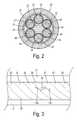
- FIG. 2is a radial cross section of a multi-phase percutaneous cable used in the present invention.
- FIG. 3is a longitudinal side view of the cable of FIG. 2 .
- FIG. 4is a radial cross section showing a first embodiment for pairing redundant conductors.
- FIG. 5is a radial cross section showing a second embodiment for pairing redundant conductors.
- FIG. 1shows a ventricular assist system in which a pump unit 10 is driven by an inverter 11 in an external control unit.
- a percutaneous cable 12couples inverter 11 to a motor 13 in pump unit 10 .
- Inverter 11has a first phase 14 , a second phase 15 , and a third phase 16 .
- Each phasehas a pair of redundant phase legs with respective upper and lower power switches.
- Each phase legis connected to a respective terminal on a terminal block 17 .
- Cable 12includes conductors 20 - 25 connected between terminal block 17 and a terminal block 18 in pump unit 10 .
- Conductors 20 and 21redundantly carry the drive signals for phase 14
- conductors 22 and 23redundantly carry the drive signals for phase 15
- conductors 24 and 25redundantly carry the drive signals for phase 16 .
- the redundant drive signalsare joined in pump unit 10 and are coupled to motor 13 in order to drive respective motor windings.
- a percutaneous cable 20is shown in radial cross-section having six separate conductors 22 - 27 arranged concentrically around a cable core 21 .
- Cable core 21may be comprised of a conventional moldable material such as a fiber fill having an appropriate strength and flexibility. Core 21 may be extruded between and around conductors 22 - 27 as shown at 28 .
- Each individual conductor 22 - 27is preferably comprised of a large number of twisted wire strands enclosed in a separate insulating cover 32 - 37 .
- a liner 30 and an outer jacket 31may also be provided around the conductors and cable core to provide a highly reliable and durable cable structure.
- Cable 20is of a generally cylindrical shape. It is capable of being sterilized for implantation and is made of biocompatible materials with sufficient flexibility and strength to perform as a percutaneous cable. Conductors 22 - 27 may be preferably helically twisted within cable 20 to enhance the flexibility. After repeated flexing during in-service usage, however, a fracture or crack 40 may eventually appear in one of the individual conductors such as conductor 26 . As a result of fracture 40 , mechanical stress becomes concentrated in that location since the overall cable structure is weakened. Due to the concentrated stress and the loss of localized strength, increased forces are applied to the adjacent conductors so that the fracture may spread at 40 a in conductor 25 and 40 b in conductor 27 . Thus, the likelihood increases that the next conductor to fail will be one of the adjacent conductors.
- the present inventionadopts a connection scheme for the redundant conductors in which individual conductors of each pair are separated by at least one conductor of a different conductor pair in the concentric arrangement around the cable core.
- the external control unitincludes an H-bridge inverter having first, second, and third phase legs designated A, B, and C.
- Each phase legmust be connected to a respective junction between first, second, and third phases of a multiphase stator in an implantable pump.
- Each conductor pair of the cableconnects a respective phase leg to a respective junction.
- conductors A1 and A2 of a redundant conductor pairare placed in diametric opposition.
- conductors B1 and B2 for phase B and conductors C1 and C2 for phase Care each placed in diametric opposition.
- each conductor of any particular pairis separated from its mate by at least two conductors from other redundant pairs.
- the percutaneous cablemay include more than six conductors.
- there may be more than three phase pairs of conductorsi.e., the pump motor may have more than three phases
- the cablemay also include conductors carrying other types of signals (e.g., sensor signals).
- additional conductorsmay also be arranged concentrically around the cable core.
- an effected conductor beneath or involving the fracturewill have its redundant conductor partner on the diametrically opposite side of the cable so that the partner will be least affected by any concentrated or increased stress that is created by continued flexing of the cable.
- FIG. 5shows an alternative embodiment of the arranged conductor pairs in which some or all of the conductor pairs are not in full diametric opposition yet they are still separated by at least one conductor of a different conductor pair.
- a conductor pair A1/A2is separated by an intervening conductor B1 for the phase B pair.
- a pair of conductors C1/C2is separated by a conductor B2.
Landscapes
- Health & Medical Sciences (AREA)
- Heart & Thoracic Surgery (AREA)
- Engineering & Computer Science (AREA)
- Cardiology (AREA)
- Life Sciences & Earth Sciences (AREA)
- Anesthesiology (AREA)
- Biomedical Technology (AREA)
- Hematology (AREA)
- Mechanical Engineering (AREA)
- Animal Behavior & Ethology (AREA)
- General Health & Medical Sciences (AREA)
- Public Health (AREA)
- Veterinary Medicine (AREA)
- Vascular Medicine (AREA)
- External Artificial Organs (AREA)
- Prostheses (AREA)
Abstract
Description
Claims (5)
Priority Applications (2)
| Application Number | Priority Date | Filing Date | Title |
|---|---|---|---|
| US13/849,704US9192705B2 (en) | 2013-03-25 | 2013-03-25 | Percutaneous cable with redundant conductors for implantable blood pump |
| PCT/US2014/031415WO2014160602A1 (en) | 2013-03-25 | 2014-03-21 | Percutaneous cable with redundant conductors for implantable blood pump |
Applications Claiming Priority (1)
| Application Number | Priority Date | Filing Date | Title |
|---|---|---|---|
| US13/849,704US9192705B2 (en) | 2013-03-25 | 2013-03-25 | Percutaneous cable with redundant conductors for implantable blood pump |
Publications (2)
| Publication Number | Publication Date |
|---|---|
| US20140288352A1 US20140288352A1 (en) | 2014-09-25 |
| US9192705B2true US9192705B2 (en) | 2015-11-24 |
Family
ID=51569626
Family Applications (1)
| Application Number | Title | Priority Date | Filing Date |
|---|---|---|---|
| US13/849,704Expired - Fee RelatedUS9192705B2 (en) | 2013-03-25 | 2013-03-25 | Percutaneous cable with redundant conductors for implantable blood pump |
Country Status (2)
| Country | Link |
|---|---|
| US (1) | US9192705B2 (en) |
| WO (1) | WO2014160602A1 (en) |
Cited By (25)
| Publication number | Priority date | Publication date | Assignee | Title |
|---|---|---|---|---|
| CN109450317A (en)* | 2018-11-19 | 2019-03-08 | 北京航空航天大学 | Electric Armoured Vehicle fault tolerant permanent magnet hub motor drive control device and control method |
| US10722631B2 (en) | 2018-02-01 | 2020-07-28 | Shifamed Holdings, Llc | Intravascular blood pumps and methods of use and manufacture |
| US11185677B2 (en) | 2017-06-07 | 2021-11-30 | Shifamed Holdings, Llc | Intravascular fluid movement devices, systems, and methods of use |
| US11368081B2 (en) | 2018-01-24 | 2022-06-21 | Kardion Gmbh | Magnetic coupling element with a magnetic bearing function |
| US11511103B2 (en) | 2017-11-13 | 2022-11-29 | Shifamed Holdings, Llc | Intravascular fluid movement devices, systems, and methods of use |
| US11654275B2 (en) | 2019-07-22 | 2023-05-23 | Shifamed Holdings, Llc | Intravascular blood pumps with struts and methods of use and manufacture |
| US11724089B2 (en) | 2019-09-25 | 2023-08-15 | Shifamed Holdings, Llc | Intravascular blood pump systems and methods of use and control thereof |
| US11754075B2 (en) | 2018-07-10 | 2023-09-12 | Kardion Gmbh | Impeller for an implantable, vascular support system |
| US11944805B2 (en) | 2020-01-31 | 2024-04-02 | Kardion Gmbh | Pump for delivering a fluid and method of manufacturing a pump |
| US11964145B2 (en) | 2019-07-12 | 2024-04-23 | Shifamed Holdings, Llc | Intravascular blood pumps and methods of manufacture and use |
| US12005248B2 (en) | 2018-05-16 | 2024-06-11 | Kardion Gmbh | Rotor bearing system |
| US12064615B2 (en) | 2018-05-30 | 2024-08-20 | Kardion Gmbh | Axial-flow pump for a ventricular assist device and method for producing an axial-flow pump for a ventricular assist device |
| US12076549B2 (en) | 2018-07-20 | 2024-09-03 | Kardion Gmbh | Feed line for a pump unit of a cardiac assistance system, cardiac assistance system and method for producing a feed line for a pump unit of a cardiac assistance system |
| US12102815B2 (en) | 2019-09-25 | 2024-10-01 | Shifamed Holdings, Llc | Catheter blood pumps and collapsible pump housings |
| US12107474B2 (en) | 2018-05-16 | 2024-10-01 | Kardion Gmbh | End-face rotating joint for transmitting torques |
| US12121713B2 (en) | 2019-09-25 | 2024-10-22 | Shifamed Holdings, Llc | Catheter blood pumps and collapsible blood conduits |
| US12144976B2 (en) | 2018-06-21 | 2024-11-19 | Kardion Gmbh | Method and device for detecting a wear condition of a ventricular assist device and for operating same, and ventricular assist device |
| US12161857B2 (en) | 2018-07-31 | 2024-12-10 | Shifamed Holdings, Llc | Intravascular blood pumps and methods of use |
| US12194287B2 (en) | 2018-05-30 | 2025-01-14 | Kardion Gmbh | Method of manufacturing electrical conductor tracks in a region of an intravascular blood pump |
| US12201823B2 (en) | 2018-05-30 | 2025-01-21 | Kardion Gmbh | Line device for conducting a blood flow for a heart support system, heart support system, and method for producing a line device |
| US12220570B2 (en) | 2018-10-05 | 2025-02-11 | Shifamed Holdings, Llc | Intravascular blood pumps and methods of use |
| US12263333B2 (en) | 2018-06-21 | 2025-04-01 | Kardion Gmbh | Stator vane device for guiding the flow of a fluid flowing out of an outlet opening of a ventricular assist device, ventricular assist device with stator vane device, method for operating a stator vane device and manufacturing method |
| US12383727B2 (en) | 2018-05-30 | 2025-08-12 | Kardion Gmbh | Motor housing module for a heart support system, and heart support system and method for mounting a heart support system |
| US12390633B2 (en) | 2018-08-07 | 2025-08-19 | Kardion Gmbh | Bearing device for a heart support system, and method for rinsing a space in a bearing device for a heart support system |
| US12409310B2 (en) | 2019-12-11 | 2025-09-09 | Shifamed Holdings, Llc | Descending aorta and vena cava blood pumps |
Families Citing this family (7)
| Publication number | Priority date | Publication date | Assignee | Title |
|---|---|---|---|---|
| US9308305B2 (en) | 2014-06-18 | 2016-04-12 | Ch Biomedical (Usa) Inc. | Implantable blood pump with integrated controller |
| JP6228713B1 (en)* | 2014-09-03 | 2017-11-08 | ティーシー1 エルエルシー | Triple helical driveline cable and method of assembly and use |
| WO2018057795A1 (en)* | 2016-09-26 | 2018-03-29 | Tc1 Llc | Heart pump driveline power modulation |
| JP6407948B2 (en) | 2016-12-21 | 2018-10-17 | ファナック株式会社 | Polyphase transformer |
| US11013905B2 (en)* | 2017-05-11 | 2021-05-25 | Tci Llc | Thermal interconnect for implantable blood pump |
| WO2019152363A1 (en) | 2018-01-31 | 2019-08-08 | Heartware, Inc. | Axial blood pump with impeller rinse operation |
| CN111757761B (en)* | 2018-05-10 | 2024-07-12 | 心脏器械股份有限公司 | Axial flow pump pressure algorithm with field oriented control |
Citations (19)
| Publication number | Priority date | Publication date | Assignee | Title |
|---|---|---|---|---|
| US4434389A (en)* | 1980-10-28 | 1984-02-28 | Kollmorgen Technologies Corporation | Motor with redundant windings |
| US4665896A (en)* | 1985-07-22 | 1987-05-19 | Novacor Medical Corporation | Power supply for body implant and method of use |
| US4895557A (en) | 1987-12-07 | 1990-01-23 | Nimbus Medical, Inc. | Drive mechanism for powering intravascular blood pumps |
| US5613935A (en)* | 1994-12-16 | 1997-03-25 | Jarvik; Robert | High reliability cardiac assist system |
| US20010002234A1 (en)* | 1997-09-05 | 2001-05-31 | Knobbe, Martens, Olson & Bear,Llp | Rotary pump with exclusively hydrodynamically suspended impeller |
| US6351048B1 (en)* | 1999-06-22 | 2002-02-26 | Levitronix Llc | Electrical rotary drive |
| US6486405B2 (en) | 2000-12-01 | 2002-11-26 | Hon Hai Precision Ind. Co., Ltd. | Arrangement of differential pair for eliminating crosstalk in high speed application |
| US6785576B2 (en) | 1997-04-21 | 2004-08-31 | Medtronic, Inc. | Medical electrical lead |
| US20050025630A1 (en)* | 1999-04-23 | 2005-02-03 | Ayre Peter Joseph | Rotary blood pump and control system therefor |
| US6925334B1 (en) | 2003-08-04 | 2005-08-02 | Pacesetter, Inc. | Implantable medical lead having multiple, jointly insulated electrical conductors |
| US7734354B1 (en) | 2006-08-04 | 2010-06-08 | Advanced Neuromodulation Systems, Inc. | Stimulation lead, stimulation system, and method for limiting MRI induced current in a stimulation lead |
| US20100305692A1 (en)* | 2009-05-27 | 2010-12-02 | Thomas Douglas C | Monitoring of redundant conductors |
| US20110071336A1 (en) | 2009-09-21 | 2011-03-24 | Barry Yomtov | Hard-wired implanted controller system |
| US20110160516A1 (en) | 2009-12-30 | 2011-06-30 | Thoratec Corporation | Mobility-Enhancing Blood Pump System |
| US8382830B2 (en) | 2007-06-06 | 2013-02-26 | World Heart Corporation | Implantable VAD with replaceable percutaneous cable |
| US8388384B2 (en) | 2010-06-07 | 2013-03-05 | Thoratec Corporation | Bi-ventricular percutaneous cable |
| US20130289334A1 (en)* | 2011-07-11 | 2013-10-31 | Kurt D. Badstibner | Transcutaneous power transmission and communication for implanted heart assist and other devices |
| US8652024B1 (en) | 2013-01-23 | 2014-02-18 | Thoratec Corporation | Sterilizable cable system for implantable blood pump |
| US20140200389A1 (en)* | 2013-01-16 | 2014-07-17 | Thoratec Corporation | Motor fault monitor for implantable blood pump |
- 2013
- 2013-03-25USUS13/849,704patent/US9192705B2/ennot_activeExpired - Fee Related
- 2014
- 2014-03-21WOPCT/US2014/031415patent/WO2014160602A1/enactiveApplication Filing
Patent Citations (19)
| Publication number | Priority date | Publication date | Assignee | Title |
|---|---|---|---|---|
| US4434389A (en)* | 1980-10-28 | 1984-02-28 | Kollmorgen Technologies Corporation | Motor with redundant windings |
| US4665896A (en)* | 1985-07-22 | 1987-05-19 | Novacor Medical Corporation | Power supply for body implant and method of use |
| US4895557A (en) | 1987-12-07 | 1990-01-23 | Nimbus Medical, Inc. | Drive mechanism for powering intravascular blood pumps |
| US5613935A (en)* | 1994-12-16 | 1997-03-25 | Jarvik; Robert | High reliability cardiac assist system |
| US6785576B2 (en) | 1997-04-21 | 2004-08-31 | Medtronic, Inc. | Medical electrical lead |
| US20010002234A1 (en)* | 1997-09-05 | 2001-05-31 | Knobbe, Martens, Olson & Bear,Llp | Rotary pump with exclusively hydrodynamically suspended impeller |
| US20050025630A1 (en)* | 1999-04-23 | 2005-02-03 | Ayre Peter Joseph | Rotary blood pump and control system therefor |
| US6351048B1 (en)* | 1999-06-22 | 2002-02-26 | Levitronix Llc | Electrical rotary drive |
| US6486405B2 (en) | 2000-12-01 | 2002-11-26 | Hon Hai Precision Ind. Co., Ltd. | Arrangement of differential pair for eliminating crosstalk in high speed application |
| US6925334B1 (en) | 2003-08-04 | 2005-08-02 | Pacesetter, Inc. | Implantable medical lead having multiple, jointly insulated electrical conductors |
| US7734354B1 (en) | 2006-08-04 | 2010-06-08 | Advanced Neuromodulation Systems, Inc. | Stimulation lead, stimulation system, and method for limiting MRI induced current in a stimulation lead |
| US8382830B2 (en) | 2007-06-06 | 2013-02-26 | World Heart Corporation | Implantable VAD with replaceable percutaneous cable |
| US20100305692A1 (en)* | 2009-05-27 | 2010-12-02 | Thomas Douglas C | Monitoring of redundant conductors |
| US20110071336A1 (en) | 2009-09-21 | 2011-03-24 | Barry Yomtov | Hard-wired implanted controller system |
| US20110160516A1 (en) | 2009-12-30 | 2011-06-30 | Thoratec Corporation | Mobility-Enhancing Blood Pump System |
| US8388384B2 (en) | 2010-06-07 | 2013-03-05 | Thoratec Corporation | Bi-ventricular percutaneous cable |
| US20130289334A1 (en)* | 2011-07-11 | 2013-10-31 | Kurt D. Badstibner | Transcutaneous power transmission and communication for implanted heart assist and other devices |
| US20140200389A1 (en)* | 2013-01-16 | 2014-07-17 | Thoratec Corporation | Motor fault monitor for implantable blood pump |
| US8652024B1 (en) | 2013-01-23 | 2014-02-18 | Thoratec Corporation | Sterilizable cable system for implantable blood pump |
Non-Patent Citations (2)
| Title |
|---|
| International Search report and Written Opinion from PCT/US2014/012448 mailed on Feb. 19, 2014, 8 pages. |
| International Search Report and Written Opinion from PCT/US2014/031415 mailed on Aug. 8, 2014, 13 pages. |
Cited By (29)
| Publication number | Priority date | Publication date | Assignee | Title |
|---|---|---|---|---|
| US11185677B2 (en) | 2017-06-07 | 2021-11-30 | Shifamed Holdings, Llc | Intravascular fluid movement devices, systems, and methods of use |
| US11717670B2 (en) | 2017-06-07 | 2023-08-08 | Shifamed Holdings, LLP | Intravascular fluid movement devices, systems, and methods of use |
| US11511103B2 (en) | 2017-11-13 | 2022-11-29 | Shifamed Holdings, Llc | Intravascular fluid movement devices, systems, and methods of use |
| US11804767B2 (en) | 2018-01-24 | 2023-10-31 | Kardion Gmbh | Magnetic coupling element with a magnetic bearing function |
| US11368081B2 (en) | 2018-01-24 | 2022-06-21 | Kardion Gmbh | Magnetic coupling element with a magnetic bearing function |
| US10722631B2 (en) | 2018-02-01 | 2020-07-28 | Shifamed Holdings, Llc | Intravascular blood pumps and methods of use and manufacture |
| US11229784B2 (en) | 2018-02-01 | 2022-01-25 | Shifamed Holdings, Llc | Intravascular blood pumps and methods of use and manufacture |
| US12076545B2 (en) | 2018-02-01 | 2024-09-03 | Shifamed Holdings, Llc | Intravascular blood pumps and methods of use and manufacture |
| US12107474B2 (en) | 2018-05-16 | 2024-10-01 | Kardion Gmbh | End-face rotating joint for transmitting torques |
| US12005248B2 (en) | 2018-05-16 | 2024-06-11 | Kardion Gmbh | Rotor bearing system |
| US12064615B2 (en) | 2018-05-30 | 2024-08-20 | Kardion Gmbh | Axial-flow pump for a ventricular assist device and method for producing an axial-flow pump for a ventricular assist device |
| US12383727B2 (en) | 2018-05-30 | 2025-08-12 | Kardion Gmbh | Motor housing module for a heart support system, and heart support system and method for mounting a heart support system |
| US12201823B2 (en) | 2018-05-30 | 2025-01-21 | Kardion Gmbh | Line device for conducting a blood flow for a heart support system, heart support system, and method for producing a line device |
| US12194287B2 (en) | 2018-05-30 | 2025-01-14 | Kardion Gmbh | Method of manufacturing electrical conductor tracks in a region of an intravascular blood pump |
| US12144976B2 (en) | 2018-06-21 | 2024-11-19 | Kardion Gmbh | Method and device for detecting a wear condition of a ventricular assist device and for operating same, and ventricular assist device |
| US12263333B2 (en) | 2018-06-21 | 2025-04-01 | Kardion Gmbh | Stator vane device for guiding the flow of a fluid flowing out of an outlet opening of a ventricular assist device, ventricular assist device with stator vane device, method for operating a stator vane device and manufacturing method |
| US11754075B2 (en) | 2018-07-10 | 2023-09-12 | Kardion Gmbh | Impeller for an implantable, vascular support system |
| US12076549B2 (en) | 2018-07-20 | 2024-09-03 | Kardion Gmbh | Feed line for a pump unit of a cardiac assistance system, cardiac assistance system and method for producing a feed line for a pump unit of a cardiac assistance system |
| US12161857B2 (en) | 2018-07-31 | 2024-12-10 | Shifamed Holdings, Llc | Intravascular blood pumps and methods of use |
| US12390633B2 (en) | 2018-08-07 | 2025-08-19 | Kardion Gmbh | Bearing device for a heart support system, and method for rinsing a space in a bearing device for a heart support system |
| US12220570B2 (en) | 2018-10-05 | 2025-02-11 | Shifamed Holdings, Llc | Intravascular blood pumps and methods of use |
| CN109450317A (en)* | 2018-11-19 | 2019-03-08 | 北京航空航天大学 | Electric Armoured Vehicle fault tolerant permanent magnet hub motor drive control device and control method |
| US11964145B2 (en) | 2019-07-12 | 2024-04-23 | Shifamed Holdings, Llc | Intravascular blood pumps and methods of manufacture and use |
| US11654275B2 (en) | 2019-07-22 | 2023-05-23 | Shifamed Holdings, Llc | Intravascular blood pumps with struts and methods of use and manufacture |
| US12121713B2 (en) | 2019-09-25 | 2024-10-22 | Shifamed Holdings, Llc | Catheter blood pumps and collapsible blood conduits |
| US12102815B2 (en) | 2019-09-25 | 2024-10-01 | Shifamed Holdings, Llc | Catheter blood pumps and collapsible pump housings |
| US11724089B2 (en) | 2019-09-25 | 2023-08-15 | Shifamed Holdings, Llc | Intravascular blood pump systems and methods of use and control thereof |
| US12409310B2 (en) | 2019-12-11 | 2025-09-09 | Shifamed Holdings, Llc | Descending aorta and vena cava blood pumps |
| US11944805B2 (en) | 2020-01-31 | 2024-04-02 | Kardion Gmbh | Pump for delivering a fluid and method of manufacturing a pump |
Also Published As
| Publication number | Publication date |
|---|---|
| WO2014160602A1 (en) | 2014-10-02 |
| US20140288352A1 (en) | 2014-09-25 |
Similar Documents
| Publication | Publication Date | Title |
|---|---|---|
| US9192705B2 (en) | Percutaneous cable with redundant conductors for implantable blood pump | |
| US8968174B2 (en) | Motor fault monitor for implantable blood pump | |
| US8837096B2 (en) | Fault monitor for fault tolerant implantable pump | |
| EP3189526B1 (en) | Triple helix driveline cable and methods of assembly and use | |
| US10874780B2 (en) | Silver motor stator for implantable blood pump | |
| CN110214035B (en) | blood pump | |
| EP3990047B1 (en) | Intravascular blood pump having multilayer coreless coils | |
| US20140275721A1 (en) | Centrifugal Blood Pump With Partitioned Implantable Device | |
| US5843129A (en) | Electrical circuit for equipment requiring redundant flow paths and method of use | |
| CN109789258A (en) | For controlling the Field orientable control of blood pump motor | |
| WO2017040317A1 (en) | Blood pump controllers and methods of use for improved energy efficiency | |
| US20170173238A1 (en) | Implantable mechanical circulatory support devices | |
| CN103023170A (en) | Connection module for a bar wound stator assembly and method of manufacturing a bar wound stator assembly | |
| CN118631129B (en) | Fault handling method and device for ventricular assist device | |
| CN223334528U (en) | Motor, coil, and ventricular assist device |
Legal Events
| Date | Code | Title | Description |
|---|---|---|---|
| AS | Assignment | Owner name:TERUMO KABUSHIKI KAISHA, JAPAN Free format text:ASSIGNMENT OF ASSIGNORS INTEREST;ASSIGNOR:YANAI, MASAMICHI;REEL/FRAME:030166/0017 Effective date:20130325 | |
| AS | Assignment | Owner name:TERUMO KABUSHIKI KAISHA, JAPAN Free format text:ASSIGNMENT OF ASSIGNORS INTEREST;ASSIGNOR:BHATT, HIMANSHU K.;REEL/FRAME:030448/0735 Effective date:20130520 | |
| AS | Assignment | Owner name:THORATEC CORPORATION, CALIFORNIA Free format text:ASSIGNMENT OF ASSIGNORS INTEREST;ASSIGNOR:TERUMO KABUSHIKI KAISHA;REEL/FRAME:031016/0364 Effective date:20130630 | |
| STCF | Information on status: patent grant | Free format text:PATENTED CASE | |
| AS | Assignment | Owner name:THORATEC LLC, CALIFORNIA Free format text:CHANGE OF NAME;ASSIGNOR:THORATEC CORPORATION;REEL/FRAME:041428/0327 Effective date:20151112 Owner name:TC1 LLC, CALIFORNIA Free format text:ASSIGNMENT OF ASSIGNORS INTEREST;ASSIGNOR:THORATEC LLC;REEL/FRAME:041428/0685 Effective date:20161114 | |
| MAFP | Maintenance fee payment | Free format text:PAYMENT OF MAINTENANCE FEE, 4TH YEAR, LARGE ENTITY (ORIGINAL EVENT CODE: M1551); ENTITY STATUS OF PATENT OWNER: LARGE ENTITY Year of fee payment:4 | |
| FEPP | Fee payment procedure | Free format text:MAINTENANCE FEE REMINDER MAILED (ORIGINAL EVENT CODE: REM.); ENTITY STATUS OF PATENT OWNER: LARGE ENTITY | |
| LAPS | Lapse for failure to pay maintenance fees | Free format text:PATENT EXPIRED FOR FAILURE TO PAY MAINTENANCE FEES (ORIGINAL EVENT CODE: EXP.); ENTITY STATUS OF PATENT OWNER: LARGE ENTITY | |
| STCH | Information on status: patent discontinuation | Free format text:PATENT EXPIRED DUE TO NONPAYMENT OF MAINTENANCE FEES UNDER 37 CFR 1.362 | |
| FP | Lapsed due to failure to pay maintenance fee | Effective date:20231124 |