US9192397B2 - Devices and methods for fracture reduction - Google Patents
Devices and methods for fracture reductionDownload PDFInfo
- Publication number
- US9192397B2 US9192397B2US12/486,439US48643909AUS9192397B2US 9192397 B2US9192397 B2US 9192397B2US 48643909 AUS48643909 AUS 48643909AUS 9192397 B2US9192397 B2US 9192397B2
- Authority
- US
- United States
- Prior art keywords
- assembly
- drilling device
- balloon
- lumen
- shaft
- Prior art date
- Legal status (The legal status is an assumption and is not a legal conclusion. Google has not performed a legal analysis and makes no representation as to the accuracy of the status listed.)
- Active, expires
Links
Images


Classifications
- A—HUMAN NECESSITIES
- A61—MEDICAL OR VETERINARY SCIENCE; HYGIENE
- A61B—DIAGNOSIS; SURGERY; IDENTIFICATION
- A61B17/00—Surgical instruments, devices or methods
- A61B17/16—Instruments for performing osteoclasis; Drills or chisels for bones; Trepans
- A61B17/1662—Instruments for performing osteoclasis; Drills or chisels for bones; Trepans for particular parts of the body
- A61B17/1671—Instruments for performing osteoclasis; Drills or chisels for bones; Trepans for particular parts of the body for the spine
- A—HUMAN NECESSITIES
- A61—MEDICAL OR VETERINARY SCIENCE; HYGIENE
- A61B—DIAGNOSIS; SURGERY; IDENTIFICATION
- A61B17/00—Surgical instruments, devices or methods
- A61B17/16—Instruments for performing osteoclasis; Drills or chisels for bones; Trepans
- A61B17/1613—Component parts
- A61B17/1615—Drill bits, i.e. rotating tools extending from a handpiece to contact the worked material
- A61B17/1617—Drill bits, i.e. rotating tools extending from a handpiece to contact the worked material with mobile or detachable parts
- A—HUMAN NECESSITIES
- A61—MEDICAL OR VETERINARY SCIENCE; HYGIENE
- A61B—DIAGNOSIS; SURGERY; IDENTIFICATION
- A61B17/00—Surgical instruments, devices or methods
- A61B17/16—Instruments for performing osteoclasis; Drills or chisels for bones; Trepans
- A61B17/1613—Component parts
- A61B17/1631—Special drive shafts, e.g. flexible shafts
- A—HUMAN NECESSITIES
- A61—MEDICAL OR VETERINARY SCIENCE; HYGIENE
- A61B—DIAGNOSIS; SURGERY; IDENTIFICATION
- A61B17/00—Surgical instruments, devices or methods
- A61B17/16—Instruments for performing osteoclasis; Drills or chisels for bones; Trepans
- A61B17/1642—Instruments for performing osteoclasis; Drills or chisels for bones; Trepans for producing a curved bore
- A—HUMAN NECESSITIES
- A61—MEDICAL OR VETERINARY SCIENCE; HYGIENE
- A61B—DIAGNOSIS; SURGERY; IDENTIFICATION
- A61B17/00—Surgical instruments, devices or methods
- A61B17/56—Surgical instruments or methods for treatment of bones or joints; Devices specially adapted therefor
- A61B17/58—Surgical instruments or methods for treatment of bones or joints; Devices specially adapted therefor for osteosynthesis, e.g. bone plates, screws or setting implements
- A61B17/88—Osteosynthesis instruments; Methods or means for implanting or extracting internal or external fixation devices
- A61B17/885—Tools for expanding or compacting bones or discs or cavities therein
- A61B17/8852—Tools for expanding or compacting bones or discs or cavities therein capable of being assembled or enlarged, or changing shape, inside the bone or disc
- A61B17/8855—Tools for expanding or compacting bones or discs or cavities therein capable of being assembled or enlarged, or changing shape, inside the bone or disc inflatable, e.g. kyphoplasty balloons
Definitions
- the present inventionrelates generally to the field of orthopedic devices to treat fractured bone in the spine, and more particularly to an orthopedic instrument and implant system that can be used to facilitate bone cement treatment of a vertebral compression fracture.
- osteoporosis and other metabolic bone conditionsweaken the bone structure and predispose the bone to fracture. If not treated, certain fractures and bone defects of the vertebral body may produce intolerable pain, and may lead to the development of deformity and severe medical complications.
- Bone weakeningmay also result from benign or malignant lesions of the spinal column. Tumors often compromise the structural integrity of the bone and thus require surgical stabilization and repair of defects with biocompatible materials such as bone grafts or cements. Bone tumors of the spine are relatively common, and many cause vertebral compression fracture.
- osteoporotic compression fractures of the vertebraeoccur each year in the United States—primarily in the elderly female population. Until recently, treatment of such fractures was limited to conservative, non-operative therapies such as bed rest, bracing, and medications.
- vertebral compression fracturecan include injecting or filling the fracture bone or bone defect with biocompatible bone cement.
- a relatively new procedure known as “vertebroplasty”was developed in the mid 1980's to address the inadequacy of conservative treatment for vertebral body fracture. This procedure involves injecting radio-opaque bone cement directly into a fracture void, through a minimally invasive cannula or needle, under fluoroscopic control. The cement is pressurized by a syringe or similar plunger mechanism, thus causing the cement to fill the void and penetrate the interstices of a broken trabecular bone. Once cured, the cement stabilizes the fracture and eliminates or reduces pain.
- Bone cementsare generally formulations of non-resorbable biocompatible polymers such as PMMA (polymethylmethacrylate), or resorbable calcium phosphate cements which allow for the gradual replacement of the cement with living bone. Both types of bone cements have been used successfully in the treatment of bone defects secondary to compression fractures of the vertebral body.
- PMMApolymethylmethacrylate
- calcium phosphate cementswhich allow for the gradual replacement of the cement with living bone. Both types of bone cements have been used successfully in the treatment of bone defects secondary to compression fractures of the vertebral body.
- Balloon tampis inserted into the vertebral body via a cannula approach to expand or distract the fractured bone and create a void within the cancellous structure.
- Balloon tampsare inflated using pressurized fluid such as saline solution.
- pressurized fluidsuch as saline solution.
- the inflation of a balloon membrane within the boneproduces radial expansion forces on the surface of the membrane and forms a cavity in the bone.
- the membraneleaves a cavity that is subsequently filled with bone cement.
- the formation of a cavity within the boneallows for the injection of more viscous cement material, which may be relatively less prone to leakage.
- the balloonis also effective at “reducing” the fracture and restoring anatomic shape to a fractured body.
- balloon dilatation in boneis maximally effective if the balloon device is targeted inferior to, or below, the fracture plane.
- the balloon dilatationmay distract, or lift, a fracture bone fragment, such as the vertebral body endplate.
- Devices and methods including curving drill devices and curving reamer deviceshave been developed to improve the targeting of a fracture and forming a cavity in a more anatomically desirable location. See, for example, U.S. patent application Ser. No. 11/957,022 to Crainich et al., the disclosure of which is being incorporated herein by reference in its entirety.
- the purpose of the present disclosureis to define improvements in vertebroplasty instrument systems to facilitate targeting of a fracture, including novel devices and methods for distracting broken bone fragments, create a cavity, and/or treating the fracture with bone cement injection.
- the present inventionis directed, in one embodiment, towards novel methods and devices for preparing a cavity in bone, and/or distracting broken bone fragments.
- the methods and devices disclosed hereincan allow a cavity to be created in a vertebral body along a curvilinear pathway which has been targeted, for example, to a location including broken bone fragments.
- On aspect of the inventionincludes a method of forming a curvilinear void in a bony structure, such as, but not limited to, a vertebral body.
- the methodmay include the steps of accessing a bony structure with a cannula, inserting a distal end of a drill device through the cannula and into the bony structure, and manipulating the distal end of the drill device to create a curvilinear void in the bony structure.
- the methodmay further include enlarging the void by expanding a balloon element mounted to the drill device and thereafter deflating the balloon element and removing the drill device from the cannula.
- the balloon elementis expanded by fluid pressure.
- the step of manipulating of the distal end of the drill devicemay include a simultaneous rotation and curvilinear translation of the distal end of the drill device.
- the cannulamay be substantially straight or at least partially curvilinear.
- the drilling devicemay include a flexible drill shaft assembly.
- the flexible drill shaft assemblyincludes a sharp cutting tip, a flexible rotatable drive shaft coupled to the tip, and a flexible, moveable and non-rotatable housing.
- the drilling devicemay also include a locking means.
- the methodmay also include the steps of locking the drill device into the cannula using the locking means prior to forming the void and unlocking the drill device from the cannula after forming the void and prior to removing the distal end of the drill device.
- the drill devicemay be manipulated in response to a rotation of an element at a proximal end of the drill device.
- One embodiment of the methodmay also include the step of reaming the void produced by at least one of drilling and balloon expansion.
- the apparatusmay include a curvilinear drilling device with an expandable balloon element located at a distal portion of the drilling device.
- the balloon elementis expanded by injection of a fluid into an interior portion thereof.
- the apparatusmay also include a lumen in fluid communication with the balloon element.
- the drilling devicemay include a handle and a flexible drill shaft assembly extending from a distal end of the handle.
- the drill shaft assemblymay include a cutting tip located at a distal end of the flexible drill shaft assembly, a flexible rotatable drive shaft coupled to the tip, and a flexible, moveable and non-rotatable housing.
- the cutting tipmay be adapted to form the curvilinear void by simultaneous rotation and curvilinear translation of the cutting tip.
- the balloon elementis located substantially proximate to a distal end of the flexible, moveable and non-rotatable housing.
- the balloon elementmay be mounted to a multi-lumen assembly mounted to the drilling device.
- the multi-lumen assemblymay include a first lumen adapted to surround an elongate shaft of the drilling device and a second lumen in fluid communication with the balloon element.
- the multi-lumen assemblymay be removably or fixedly mounted onto the drilling device.
- the drill devicemay include at least one pull wire for applying a curvature to a distal end thereof.
- the drill devicemay further include at least one stiffening wire.
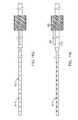
- FIG. 1Ais a schematic plan view of a Jamshidi needle and K-wire, used in accordance with one embodiment of the invention
- FIG. 1Bis a picture of a Jamshidi needle being inserted into a patient, in accordance with one embodiment of the invention
- FIG. 2Ais schematic perspective view of a trocar, used in accordance with one embodiment of the invention.
- FIG. 2Bis schematic perspective view of a cannula, in accordance with one embodiment of the invention.
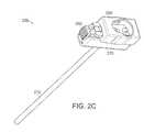
- FIG. 2Cis another schematic perspective view of the cannula of FIG. 2B ;
- FIG. 2Dis a schematic perspective view of a trocar inserted with the cannula of FIG. 2B , in accordance with one embodiment of the invention.
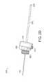
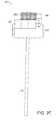
- FIG. 2Eis a schematic plan view of a cannula, in accordance with one embodiment of the invention.
- FIG. 2Fis a picture of a trocar and cannula being inserted into a patient, in accordance with one embodiment of the invention.
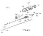
- FIG. 3Ais an exploded schematic perspective view of a drill assembly, in accordance with one embodiment of the invention.
- FIG. 3Bis a schematic perspective view of the drill assembly of FIG. 3A ;
- FIG. 3Cis a schematic side view of the drill assembly of FIG. 3A ;
- FIG. 3Dis a schematic end view of the drill assembly of FIG. 3A ;
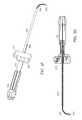
- FIG. 3Eis a schematic perspective view of another drill assembly, in accordance with one embodiment of the invention.
- FIG. 3Fis a schematic perspective view of the drill assembly of FIG. 3E inserted within a cannula, in accordance with one embodiment of the invention.
- FIG. 3Gis a sectional side view of the drill assembly of FIG. 3E inserted within a cannula;
- FIG. 3His an enlarged sectional side view of the distal end of the drill assembly of FIG. 3E ;
- FIG. 3Iis an enlarged sectional side view of the proximal end of the drill assembly of FIG. 3E inserted within a cannula;
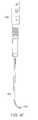
- FIG. 3Jis a schematic plan view of a drill assembly, in accordance with one embodiment of the invention.
- FIG. 3Kis a picture of a drill assembly being inserted into a patient, in accordance with one embodiment of the invention.
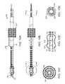
- FIG. 4Ais a schematic perspective view of a reamer assembly, in accordance with one embodiment of the invention.
- FIG. 4Bis a schematic perspective view of the reamer assembly of FIG. 4A inserted within a cannula, in accordance with one embodiment of the invention
- FIG. 4Cis a sectional side view of the reamer assembly of FIG. 4A inserted within a cannula;
- FIG. 4Dis an enlarged sectional side view of the distal end of the reamer assembly of FIG. 4A ;
- FIG. 4Eis an enlarged sectional side view of the proximal end of the reamer assembly of FIG. 4A inserted within a cannula;
- FIG. 4Fis a schematic plan view of a reamer assembly, in accordance with one embodiment of the invention.
- FIG. 4Gis a picture of a reamer assembly being inserted into a patient, in accordance with one embodiment of the invention.
- FIG. 5Ais a schematic perspective view of a needle being inserted into a vertebral body, in accordance with one embodiment of the invention.
- FIG. 5Bis a schematic perspective view of a drill assembly being inserted through a cannula into a vertebral body, in accordance with one embodiment of the invention
- FIG. 5Cis a schematic perspective view of a reamer assembly being inserted through a cannula into a vertebral body, in accordance with one embodiment of the invention.
- FIG. 6Ais a schematic side view of a drill assembly with a lever and drill cam, in accordance with one embodiment of the invention.
- FIG. 6Bis a schematic perspective view of the drill assembly of FIG. 6A ;
- FIG. 6Cis a schematic end view of the drill assembly of FIG. 6A ;
- FIG. 6Dis a schematic side view of the handle of the drill assembly of FIG. 6A ;
- FIG. 6Eis a schematic cross-sectional side view of the handle of the drill assembly of FIG. 6A through a central elongate axis of the drill assembly;
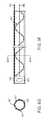
- FIG. 7Ais a schematic side view of a slotted tube sub-assembly for a drilling device with a balloon element mounted thereto, in accordance with one embodiment of the invention.
- FIG. 7Bis a cross-sectional side view of the distal end of the slotted tube sub-assembly of FIG. 7A with the balloon element in a deflated configuration;
- FIG. 7Cis a cross-sectional side view of the distal end of the slotted tube sub-assembly of FIG. 7A with the balloon element in an inflated configuration;
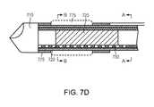
- FIG. 7Dis another cross-sectional side view of the distal end of the slotted tube sub-assembly of FIG. 7A with the balloon element in a deflated configuration, including the sections A-A and B-B;
- FIG. 7Eis a cross-sectional end view of the slotted tube sub-assembly of FIG. 7A at section A-A;
- FIG. 7Fis a cross-sectional end view of the slotted tube sub-assembly of FIG. 7A at section B-B showing the deflated balloon element and radial expansion of the balloon wall;
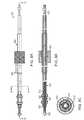
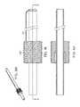
- FIG. 8Ais a schematic side view of a drill assembly with balloon element, in accordance with one embodiment of the invention.
- FIG. 8Bis a cross-sectional bottom view of the drill assembly and balloon element of FIG. 8A through section A-A;
- FIG. 8Cis a cross-sectional end view of the drill assembly and balloon element of FIG. 8A through section B-B;
- FIG. 8Dis a schematic side view of a drill tip and shaft for the drill assembly of FIG. 8A ;
- FIG. 8Eis a cross-sectional bottom view of the drill tip and shaft of FIG. 8D through section C-C;
- FIG. 8Fis a cross-sectional side view of a pull-wire and band for the drill assembly and balloon element of FIG. 8A ;
- FIG. 8Gis a cross-sectional end view of the pull-wire and band of FIG. 8F through section D-D;
- FIG. 8His a schematic perspective view of a lead-screw and key for the drill assembly and balloon element of FIG. 8A ;
- FIG. 8Iis a schematic side view of the lead-screw and key of FIG. 8H ;
- FIG. 8Jis a cross-sectional bottom view of the lead-screw and key of FIG. 8H through section E-E;
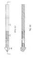
- FIG. 9Ais a schematic side view of another drill assembly with balloon element, in accordance with one embodiment of the invention.
- FIG. 9Bis a cross-sectional bottom view of the drill assembly and balloon element of FIG. 9A through section A-A;
- FIG. 9Cis a cross-sectional end view of the drill assembly and balloon element of FIG. 9A through section B-B;
- FIG. 9Dis a schematic side view of a drill tip and shaft for the drill assembly of FIG. 9A ;
- FIG. 9Eis a cross-sectional bottom view of the drill tip and shaft of FIG. 9D through section C-C;
- FIG. 9Fis a cross-sectional side view of a pull-wire and band for the drill assembly and balloon element of FIG. 9A ;
- FIG. 9Gis a cross-sectional end view of the pull-wire and band of FIG. 9F through section D-D;
- FIG. 9His a schematic perspective view of a lead-screw and key for the drill assembly and balloon element of FIG. 9A ;
- FIG. 9Iis a schematic side view of the lead-screw and key of FIG. 9H ;
- FIG. 9Jis a cross-sectional bottom view of the lead-screw and key of FIG. 9H through section E-E;
- FIG. 10Ais a schematic side view of a drill assembly with balloon element and slotted deflection shaft, in accordance with one embodiment of the invention.
- FIG. 10Bis a schematic top view of the drill assembly of FIG. 10A ;
- FIG. 10Cis a cross-sectional end view of the drill assembly of FIG. 10A through section C-C;
- FIG. 10Dis an enlarged schematic top view of the balloon element of FIG. 10A at section A;
- FIG. 10Eis a cross-sectional end view of the drill assembly of FIG. 10A through section B-B;
- FIG. 10Fis a schematic side view of a slotted deflection shaft for the drill assembly of FIG. 10A ;
- FIG. 10Gis a schematic end view of the slotted deflection shaft of FIG. 10F ;
- FIG. 10His an enlarged schematic side view of the slotted deflection shaft portion at section D;
- FIG. 10Iis a schematic top view of a puller element for the drill assembly of FIG. 10A ;
- FIG. 10Jis a schematic side view of the puller element of FIG. 10I ;
- FIG. 10Kis a schematic end view of the puller element of FIG. 10I ;
- FIG. 10Lis a schematic side view of a drill tip and shaft for the drill assembly of FIG. 10A ;
- FIG. 10Mis a cross-sectional bottom view of the drill tip and shaft of FIG. 10L through section F-F;
- FIG. 10Nis a schematic side view of a lead-screw and key for the drill assembly of FIG. 10A ;
- FIG. 10Ois a cross-sectional bottom view of the lead-screw and key of FIG. 10N through section G-G;
- FIG. 11Ais a schematic side view of another drill assembly with balloon element and slotted deflection shaft, in accordance with one embodiment of the invention.
- FIG. 11Bis a cross-sectional bottom view of the drill assembly of FIG. 11A through section F-F;
- FIG. 11Cis a schematic top view of the drill assembly of FIG. 11A ;
- FIG. 11Dis an enlarged schematic top view of the balloon element of FIG. 11A at section A;
- FIG. 11Eis a cross-sectional end view of the drill assembly of FIG. 11A through section B-B;
- FIG. 11Fis a cross-sectional end view of the drill assembly of FIG. 11A through section C-C;
- FIG. 11Gis a schematic top view of a slotted deflection shaft for the drill assembly of FIG. 11A ;
- FIG. 11His a side view of the slotted deflection shaft of FIG. 11G .
- Limitations in current balloon expanding techniquesmay be overcome through use of a drill device that curves to the central portion of the vertebral body, where, for example, displaced fragments most often occur, and where the benefits of distraction can be clinically realized.
- the expansion of a balloon element at this targeted locationmay be used to form a beneficial bone cavity defined, for example, by compacted bone fragments along its margins.
- the compacted bonemay provide a beneficial barrier to contain liquid cement material injected within the cavity. The containment and/or restriction of cement flow is desired to avoid complication associated from cement leakage in its liquid state beyond the vertebral body.
- a second benefit of cavity formationis the ability to deploy an implant that can provide beneficial containment or partial containment of liquid cement to prevent cement leakage.
- an implantable cement-directing stent deviceis disclosed in U.S. Patent Publication No. 2005/0261781 A1 to Sennett et al., the disclosure of which is incorporated herein by reference in its entirety.
- the implantable cement-directing stent deviceprovides a means for temporarily stabilizing a fractured vertebral body after cavity creation and/or during cement injection, while also directing the flow of cement anteriorly within the vertebral body to prevent unwanted cement flow near the spinal canal.
- access to the vertebral bodycan be achieved using a pointed needle or wire to pierce the skin and underlying tissue and entering into the pedicle, a depression of the vertebral body, until the needle is held fast.
- the needlecan then be pressed into the vertebral body until it is held firmly in place by the wall of the vertebral body.
- the needlecan then become a guide for the placement of subsequent devices.
- a Jamshidi needle and K-wire arrangementcan be used to provide a guide for placement of subsequent devices into the vertebral body.
- a Jamshidi Needleis a long, tapered combination needle and drill that can be used for insertion into bone.
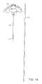
- An example Jamshidi needle and K-wirecan be seen in FIG. 1A .
- the Jamshidi needle 110can include a tapered distal end 120 and a handle 130 at its proximal end.
- the elongate Jamshidi needle 110can be hollow, to allow insertion of the K-wire 140 through the needle 140 .
- the tapered distal end 120is inserted through the skin and underlying tissue and pressed against the outer wall of the vertebral body.
- the K-wire 140can then be inserted through the hollow elongate needle 110 such that the distal end of the K-wire is forced against the wall of the vertebral body.
- the Jamshidi needle 110 and K-wire 140can be forced into the wall of the vertebral body to any depth appropriate for the procedure.
- the Jamshidi needle 110can then be removed, leaving the K-wire 140 in place to act as a guide needle for the placement of subsequent devices.
- An example of a Jamshidi needle 110 and K-wire 140 inserted through the skin and underlying tissue of a patientcan be seen in FIG. 1B .
- any appropriate needle type or other devicemay be used to provide initial access to the vertebral body.
- access to the vertebral bodycan be achieved through the use of a trocar and cannula assembly.
- This trocar and cannula assemblycan be inserted over an already inserted guide wire or needle, such as the K-wire described above, or be inserted directly without the need for a guide wire.
- the trocar and cannula assembly 200can include a trocar 210 and a cannula 220 .
- An example trocar 210is shown in FIG. 2A .
- the trocar 210includes a hollow shaft 230 with a sharpened tip 240 , and an impact handle 250 or knob coupled to the hollow shaft 230 .
- the impact handle 250also has a cylindrical locking flange 260 , for releasable interlocking with the cannula 220 .
- the trocar 210can be configured to fit over a guide wire or needle.
- the hollow cannula 220can include a thin walled straight tube 270 and a handle 275 with a locking feature 280 attached to the hollow tube 270 .
- the locking featurecan include a button, slide, latch, or other appropriate mechanism for releasable engagement with a flange.
- the locking feature 280includes a locking slide 280 and a locking slide latch 295 , wherein the locking slide latch 295 is configured to engage with the locking slide 280 and releasably hold the locking slide 280 in either a closed or open position.
- the thin walled tube 270can also have a slot 285 along its axis on the proximal side that is continuous with a slot 290 in the handle 275 .
- the tube slot 285 and the handle slot 290can be used for instrument orientation or drills, reamers, etc. disposed in the cannula 220 .
- the handle 275may be coupled to the thin walled straight tube 270 of the cannula 220 by any appropriate means, including, but not limited to, bonding, pressure fitting, threading, or any combination thereof.
- the handle 275may be a plastic, metal, or any other suitable material.
- the handle 275can include a locking feature for releasable retention of an instrument placed within the cannula 220 .
- the handle 275can include a number of holes through its length, fitted with stainless steel rods, that may be used by the surgeon, under fluoroscopy, for circumferential orientation of the handle 275 and the cannula 220 to ensure the desired relationship between the cannula 220 and the vertebral body.
- the trocar 210fits within the thin walled straight tube 270 of the cannula 220 , and releasably locks to the locking feature 280 of the cannula 220 via the locking flange 260 .
- the sharp tip 240 of the trocar 210can protrude beyond the end of the thin walled straight tube 270 of the cannula 220 .
- the cannulamay include a flexible hollow tube, or a curved hollow tube, allowing the cannula to be placed over a curved guide wire or other curved object.
- the trocar 210 and the cannula 220may be deployed over a guide needle or wire and pressed into the vertebral body, with the trocar 210 providing the displacement and/or cutting means needed to force the cannula through the skin and underlying tissue of a patient and up against, and possibly through, the wall of a vertebral body.
- the guide wiremay be a K-wire 140 as described above, or be any other appropriate needle, piercer, or guiding wire element.
- FIG. 2DAn example of a trocar 210 and guide wire 140 inserted through a cannula 220 can be seen in FIG. 2D .
- the impact handle 250 of the trocar 210is releasably coupled to the handle 275 of the cannula 220 by the locking feature 280 .
- the trocar tip 240can protrude beyond the end of the thin walled straight tube 270 of the cannula 220 and can be rotated relative to the cannula tube 270 , if desired.
- the entire trocar 210 and cannula 220 assemblyis placed over the guidewire 140 , that was previously inserted into the vertebral body.
- a small malletcan be used to tap the trocar 210 to enlarge the hole until the cannula 220 is pressed into the vertebral body to a desired depth.
- the trocar 210can then be unlatched from the handle 275 and withdrawn.
- the needle or guidewire 295can also removed, leaving the cannula 220 in place and held immovably by the wall of the vertebral body.
- FIG. 2EAn example embodiment of a cannula 220 and handle 275 can be seen in FIG. 2E .
- FIG. 2FAn example of this cannula 220 inserted into a patient can be seen in FIG. 2F .
- the next stepis to drill a curved hole in the vertebral body.
- the drilling functionis achieved by the use of a curved drilling device.
- Example curved drilling devicesare shown in FIGS. 3A-3I .
- the curved drilling devicemay include a balloon element, as shown and discussed below for FIGS. 7A-7F .
- the curved drill device 300can include a drive handle 305 , a sharp tip 310 attached to a flexible torque transmitting drive shaft 315 , and a handle drive assembly 320 .
- the flexible drive shaft 315can be secured and contained by a spring loaded, flexible, slotted metal tube 322 having a feedscrew assembly 324 attached therewith.
- the proximal end of the drive shaft 315can include a solid tube 326 bonded, or otherwise coupled, to the flexible shaft 315 component and having sufficient torque transmission capability to drive the shaft assembly.
- the rotating shaft/sharp tip 310 assemblycan further be coupled to the handle assembly 320 by a cross pin 328 , or other appropriate device, which can engage with a nut 344 located within the handle 305 and threaded onto the feedscrew assembly 324 .
- the handle drive assemblycan include a number of components to actuate the curving drill, including, but not limited to, a cap 330 for the handle, a clamp 332 for the torque tube, a locking element 334 for the torque tube, and a retainer element 336 for the torque tube.
- the retainer element 338can be coupled to a spring element 340 to provide a spring force to a band or other element configured to provide a force to the distal portion of the flexible drive shaft 315 and slotted metal tube 322 to produce the correct curvature at the distal end of the drill 300 .
- One embodiment of the inventioncan include an inner tube sized to slide within the outer slotted tube.
- This inner tubecan have an extensive laser cut opening along its distal portion. When assembled, the reduced cross section of this section of the inner tube lies adjacent to the slotted portion of the outer tube along the inside or concave side of the slotted tube.
- a compression spring of optimized stiffnesscan be coupled to the inner tube and the outer slotted tube at the proximal end by a lock washer, or other appropriate mechanism, that can be secured to a slot in the proximal end of the inner tube. When the washer is engaged, a tensile force is induced on the inner tube which causes the outer tube assembly to bend at the distal end.
- the slots on the medial sidewhich have been designed with gradually decreasing depth to encourage sequential distal to proximal deflection, can close. Therefore, when fully assembled under load of the spring, the outer slotted metal tube can assume a curved orientation with a desired radius of curvature. Since the slotted metal tube is itself flexible being made from hard temper stainless steel, or other appropriate material, it can be straightened against the force of the spring to pass through a straight cannula.
- the drive handle of the drill 300can be a two part assembly featuring a grip feature suitable to allow manual rotation, coupled to a rotator component having locking flange.
- the locking flangecan be designed to mate with the locking feature of a cannula handle to prevent axial movement but allow rotation.
- the rotator componentcan have a female thread throughout its length which can mate with a feedscrew slotted tube assembly. The feedscrew and a key are welded, or otherwise coupled, to the proximal end of the slotted tube.
- the key component 342When assembled to the hollow cannula, the key component 342 can slideably mate with the hollow cannula axial slot, which can rotationally lock the drill's curved slotted tube 322 in a preferred circumferential orientation. Therefore, when the handle assembly is rotated, the slotted tube advances in a fixed rotational orientation relative to the handle assembly at a pace equal to the thread pitch of the feedscrew.
- the rotating flexible drive shaft assemblywhich is axially constrained within the slotted metal tube 322 , also advances with the pitch of the feedscrew.
- the sharp rotating tip 310by the combined forces of the feedscrew advance and internal spring force curving the shaft, cuts and advances on a curved helical path when the handle is rotated. Conversely, when the handle is counter rotated, the sharp tip retracts along the same curved helical path. If the lock engaging the curved drill is disassembled from the cannula, the device may be slideably removed from the cannula.
- the distal end of the curved tube 322 of the drillcan be slotted, perforated, composed of a different and or thinner material, or otherwise adapted to promote bending of the distal end.
- Any appropriate materialsuch as stainless steel, aluminum, or other metal, or a plastic or composite material may be used for the drilling device, as long as the material can provide sufficient strength, flexibility, resiliency, and resistance to fatigue.
- different components of the drilling devicecan be constructed from different materials, including any of the materials described herein.
- the curved drilling device 360can include a drill tip 362 , a drill shaft 364 with a slotted portion 366 at the distal end for bending, an orientation key 368 , a drill feed unit 370 complete with a locking flange 372 and a handle 374 for rotation.
- the curved drilling device 360 releasably attached to a cannula and handle assembly 220is shown in FIG. 3F .
- the protrusionis only that of the drill tip beyond the cannula and as such, the slotted portion of the drill shaft is contained in the cannula and is therefore straight and not curved.
- the distal end of the drilling device 360is free to curve once it has been deployed beyond the distal end of the cannula.
- FIG. 3GA cross-section of the curved drilling device 360 , depicting the internal mechanisms of the system, is shown in FIG. 3G . More detailed enlarged cross-sectional diagrams are provided in FIGS. 3H and 3I .
- the drill tip 362can be welded, bonded, threaded, or otherwise coupled, to a cabled torque tube 378 that provides rotation of the tip 362 .
- the torque tube 378may be an array of wires wound in a helical, circular manner that provides torque strength with the flexibility to “go around the corner” to deliver the necessary power to the drill tip 362 to cut bone.
- a drill safety cable 380can be coupled to the drill tip 362 to promote drill tip retrieval in the unlikely event that it becomes detached from the cabled torque tube 378 .
- the slotted portion of the drill tube 366is bent into a desired arc as it exits the cannula. This is achieved by means of the band 382 , located on the inside of the bend and firmly attached to the drill shaft 364 at its distal end and attached to a compression spring assembly 384 at its proximal end. As a result, the band 382 can be held under spring tension, thus pulling on the inside of the drill shaft 364 to produce an arc, as desired.
- FIG. 3Iis a detailed cross section of the drill unit and handle, in accordance with one embodiment of the invention.
- the locking flange on the drill unitcan be retained by the locking flange of the handle. That, in turn, can be held in place by the locking slide 280 on the handle.
- the locking flange componentcan also have an internal thread or drill feed nut.
- a feed screw 386includes a matching male thread.
- the proximal end of the drill shaftcan be affixed to the feed screw 386 by welding, bonding, threading, or other means, and the feed screw 386 and drill shaft can have a key, also attached by welding or other means, to ensure the desired circumferential orientation of the drill shaft within the cannula 220 .
- the key interfacecan align the handle plane to the plane of the curved drill shaft.
- One embodimentcan also include a compression spring 388 for providing a pulling force on the band in order to bend the distal end of the drill shaft to the desired arc.
- a band retention device 390can contain the compression spring 388 .
- the compressioncan be preloaded to a desired force and the band retained to ensure that there is always tension on the band.
- the spring 388may be compressed as the band is pulled distally to allow for straightening of the drill shaft when passing through the cannula.
- the torque tube 392can go through the drill shaft and feed screw, as well as through the band retention device, and be fastened to the handle 374 by the torque retention device 394 that is keyed to the rotation handle 374 .
- the drill safety cablecan go through the entire length of the torque tube and the excess can be tied into a knot.
- a ferrulecan be staked to the drill safety cable so that it does not slide out of the torque tube inadvertently.
- the pins in the handleinteract with the slots in the drill feed unit and cause it to rotate.
- This actioncauses the feed screw to move and advance the drill while rotating the drill tip 362 for cutting.
- This motionallows the drill tip 362 to cut a curvilinear path through the interior of the vertebral body.
- the progress of the pathwaycan be monitored by use of a medical imaging technique, or be measured by means of a distance scale associated with the drill and indicating the extension of the drill tip beyond the end of the cannula.
- An example embodiment of a drill assemblycan be seen in FIG. 3H .
- An example of this drill assembly inserted into a patientcan be seen in FIG. 3I .
- the curved pathcan be created by a reamer device in the same manner as the drill device.
- the path created by the drill devicecan be enlarged by a reamer device used after the drill device has created the initial path.
- An example of a reamer deviceis shown in FIGS. 4A-4G .
- the distal end of the reameris configured for insertion through a cannula into a vertebral body.
- the reamercan include an orientation key configured to mate with a corresponding slot in the cannula to ensure that the distal end of the reamer is deployed at the correct circumferential angular orientation.
- the reamermay be releasably lockable in the cannula.
- the reamercan include a circumferentially partially slotted outer tube, wherein the slots enable the distal end of the reamer to bend in a predetermined direction.
- the reamermay include a band inserted within the outer slotted tube and coupled to the distal and the proximal ends of the reamer to bend the slotted outer tube in a predetermined direction and at a set angle.
- the proximal end of the bandmay be coupled to a compression spring to provide a predetermined amount of flex to the distal end of the reamer, thus allowing the distal end to be straightened while being inserted through the cannula, and then return to its predetermined bent configuration upon being extended beyond the end of the cannula.
- the reamermay include a reamer blade yoke configured to extend from the distal end of the outer slotted tube.
- a reamer blademay be pivotably coupled to the reamer blade yoke by a pivot pin.
- the reamermay include a cabled torque tube coupled to the reamer blade yoke to rotate the reamer blade yoke and coupled reamer blade while the outer slotted tube remains stationary.
- a cablemay be extended through the cabled torque tube and coupled to the reamer blade to provide a force to pivot the blade about the pivot point from a neutral, centered configuration to a tilted/opened configuration.
- the cablemay be attached, at the proximal end of the reamer, to a compression spring. The compression spring attached to the cable can eliminate slack in the cable and allow the angle of the reamer blade to elastically deflect from its set angle.
- the proximal end of the reamermay include a handle.
- the handlemay include a blade opening sleeve. Rotation of the blade opening sleeve can open or close the reamer blade with or without rotating the blade.
- the handlemay also include a rotation handle. Rotation of the rotation handle can rotate the reamer blade about the reamer blade yoke. Rotation of the rotation handle can also provide a proximal movement of the distal end of the reamer back towards the distal end of the cannula;
- rotation of the reamer bladewhile opening the blade, results in a semi-spherical cavity being created.
- rotation of the rotation handleprovides a rotational movement and a proximal movement of the reamer blade, allowing the reamer blade to follow a generally helical path to create a curved, generally cylindrical cavity of a length determined by the amount of rotation of the rotation handle.
- the proximal end of the reamermay include markings to indicate the amount of proximal movement of the distal end of the reamer from an original, fully extended position.
- Rotation of the blade opening sleeve in the opposite directioncan return the reamer blade to a neutral/centered orientation. Upon returning the reamer blade to the neutral/centered orientation, the reamer may be unlocked and removed from the cannula.
- the reamer devicemay be similar in construction to the drill devices described above. Both devices can have a slotted tube assembly and a flexible torque transmitting drive shaft contained therein. Both devices can have an internal tube welded, bonded, or otherwise coupled at the distal end, and joined by a washer and compression spring at the proximal end. However, the reamer device can have a moveable blade disposed at its tip. The moveable blade can be attached to a yoke by a pivot pin, and to a cable tether that is crimped, bonded, welded, or otherwise attached to the moveable blade at a location distal to the pivot pin.
- a reamer device 400 for enlarging the drilled cavity to a desired diameter and curvilinear lengthis shown in FIG. 4A .
- the reamer device 400may have similarities to the drilling device described above in that it has a shaft 405 that is slotted at the distal end 410 for curving, and the curving is produced by a band that is spring loaded by a compression spring situated between the feed screw and the band retention device.
- the reamer device 400includes a reamer blade 415 that is pivotably coupled to a yoke 420 that is mounted on the distal end of the shaft 405 .
- An orientation key 425may be mounted to the shaft 405 to engage with a slot in a cannula and ensure the correct circumferential orientation of the reamer device upon insertion.
- the reamer device 400can include a dual function handle 428 including rotation handle 430 for rotating the blade 415 , a blade opening sleeve 435 for deploying the blade, and a reamer feed nut 440 for moving the blade back and forward along the axis of the shaft as the blade is rotated.
- the proximal end of the handle 430may be a tubular molded component with gripping features on its external surface.
- the handle 430may be manufactured from any appropriate metal, plastic, ceramic, composite material, or combination thereof. Rubber or fabric elements may also be placed on the outer surface of the handle 430 to promote grip.
- FIG. 4BA cross section of the reamer device 400 , depicting the internal mechanisms of the system, is shown in FIG. 4C . More detailed cross-sectional diagrams are provided in FIGS. 4D and 4E .
- the reamer assemblymay also be retained in the cannula and handle assembly 220 in the same manner as described above for the drilling device.
- the reamer feed nut 440may work in the same way as described above for the drilling device feed nut.
- a torque tube 445can provide power for reaming (enlarging) the drilled hole, with the torque tube 445 driving the yoke 420 that houses the pivoting reamer blade 415 .
- An inner cable 450 that goes through the center of the torque tube 445can be used to tilt or open the blade 415 from the neutral position aligned with the axis of the shaft 405 to a deployed position at an angle to the axis of the shaft 405 .
- the blade 415can tilt or pivot about a pivot pin 455 coupled to the reamer blade yoke 420 .
- the curvature of the distal end of the reamer device 400can be set by a band 460 placed within the slotted tube 410 and held in tension by a spring element at the proximal end of the reamer device 400 .
- the fully deployed anglemay be set at any appropriate angle. In one embodiment, the deployment angle may be set at any angle up to 90°. For example, the fully deployed angle may be in a range from 20° to 90°, or from 30° to 70°, or from 45° to 60°.
- the curvature of the distal endmay be set to any appropriate angle by correct selection of the band length.
- a band retention device 462can hold the band 460 at the proximal end of the reamer device 400 , with a compression spring 464 coupled to the band retention device 462 to allow the shaft 405 to flex from its preferred steady state curvature during deployment through the cannula 220 and upon contact with a “hard” element within the vertebral body.
- the reamer device 400can include a multi-component, dual function handle.
- a cross-section of an example handleis shown in FIG. 4E .
- a lost feed motionmay be needed to open the reamer blade, while rotating the reamer handle, with the feed system remaining still.
- This featureis provided by means of a blade opening sleeve 435 .
- thismay be achieved by a rotation of the handle to initially “telescope” the handle from the blade opening sleeve 435 to pull on the center cable 450 to open the reamer blade 415 all while no feeding motion occurs.
- a torque tube retention device 470travels in an elongated slot in the rotation handle 430 so no proximal movement results.
- the blade opening sleeve 435retains a “T” screw 475 that provides the proximal movement of the handle for blade opening and when a blade opening nut 480 stops on the head of the T screw 475 , rotation is now transferred to the reamer feed nut 440 .
- the reamer feed nut 440 rotationpulls the feed screw 484 proximally and at the distal end the reamer blade is rotating and feeding proximally resulting in cutting bone and creating a curved cavity to desired length with fluoroscopy, or other appropriate means, for visual reference.
- the rotating handle 430is rotated counter to the cutting direction and the reamer blade 415 will fold back inward to the center starting position.
- the reamer assemblycan be unlatched from the handle and removed.
- the cannula and handle assembly 220can remain in place, however, so that further devices, such as devices that permit the insertion of the stent and the medical cement, can be inserted into the enlarged cavity.
- the cable 450 originating from the moveable blademay be fed through the entire assembled device and terminated and crimped, or otherwise coupled, to a cable retainer 490 , such as a cross pin assembly, that is coupled to the wall of the rotation handle 430 .
- a spring 492may be located within the proximal inner border of the rotation handle 430 adjacent to the cable retainer 490 .
- a threadmay by used to couple the rotation handle 430 to the remainder of the reamer device 400 .
- the dual function handle 428may induce a tensile force on the cable tether 450 by rotating the proximal molded component relative to the distal handle component to effectively lengthen the handle.
- the cable tetherthereby pulls the moveable blade 415 to cause a pivoting of the blade from a closed to an open position.
- the handle 428can then cause the rotation of the flexible drive shaft assembly to rotate the blade 415 within the cavity.
- the handle assemblyincluding the distal and proximal components, may be further secured to a rotator component having an internal thread mating the feedscrew component 484 of the slotted tube assembly.
- a rotator componenthaving an internal thread mating the feedscrew component 484 of the slotted tube assembly.
- the feedscrew rotationmay not be enabled until the reamer blade has been fully deployed via rotation of the proximal component of the handle 428 . Therefore, in one embodiment, when the rotation handle 430 is rotated, the moveable blade assembly first rotates and deploys, then translates due to the action of the feedscrew mechanism 484 . The deployed blade therefore enlarges the path to a required diameter by simultaneously rotating and translating the blade 415 .
- the direction of translationin one embodiment, is retrograde, which is achieved by the use of a left hand thread in the feedscrew 484 .
- the blade deployment from a neutral to an open positionmay only occur when the blade is rotating.
- the blade deploymentmay be independent of the blade rotation. The rate of blade deployment from a closed to an open position is dependent on the pitch of the thread which joins the proximal and distal handle component.
- the reamer devicemay be configured to drill into the vertebral body as it is advanced, before being deployed to extend the size of the cavity, as described above.
- the reamer devicecan function as both a reamer and a drill, thus eliminating the need for a separate drilling device.
- FIG. 5BAn example of a drill assembly inserted into a patient can be seen in FIG. 5B , with an example of a reamer assembly inserted into a patient shown in FIG. 5C .
- the drilling devices and/or reamer devices described hereinmay include a balloon element, such as a balloon catheter, at a distal portion thereof.
- This balloon cathetermay be configured to expand and contract, upon actuation by a user, to increase the size of the cavity created within the bony structure.
- FIGS. 7A-7FAn example drill assembly including a multi-lumen balloon catheter assembly is shown in FIGS. 7A-7F .
- a drilling device including a balloon elementmay be inserted through the cannula to drill a hole, such as, but not limited to, a curved hole, in the vertebral body.
- the drilling devicecan position a balloon element, located at a distal end of the drilling device, within the curved hole.
- This balloon elementmay then be expanded, or otherwise deployed, to expand the size of the hole inside the vertebral body.
- the balloon elementmay thereafter be retracted back to its original unexpanded state for removal of the drilling device, thereby leaving an expanded hole within the vertebral body.
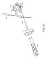
- An example curved drilling device including a balloon elementis shown in FIGS. 7A-7F .
- the drilling devicemay include a drilling element capable of forming a curvilinear pathway within a bony structure.
- This drilling elementmay, in one embodiment, be contained within one lumen of a multi-lumen balloon catheter.
- the flexible non rotating slotted metal tube 322 of the curved drill device 300may be located within one lumen of a multi-lumen balloon catheter, with a balloon element located at a distal end of the catheter.
- a multi-lumen balloon catheter assembly 705is coupled to a drilling device 710 .
- the drilling device 710may include a drill tip 715 located at a distal end of a hollow, non-rotating elongate slotted tube 720 .
- the drill tip 715may be connected to, and driven by, a torque tube 725 extending through the slotted tube 720 to a drive element located at a proximal end of the slotted tube 720 .
- the drill tip 715may be connected to the torque tube 725 at a connecting location 722 by any appropriate means, such as, but not limited to, bonding, crimping, tying, or any other appropriate mechanical, and/or adhesive means.
- the drilling device 710may additionally include elements such as a handle (not shown), a key component 730 , a feedscrew assembly 735 , a spring element 740 , and a retainer element 745 .
- the multi-lumen balloon catheter assembly 705may be placed over the torque tube 725 and extend along a length thereof.
- the multi-lumen balloon catheter assembly 705may include a first hollow shaft, or drill lumen, 750 configured to extend around the torque tube 725 , and a second hollow shaft, or balloon lumen, 755 extending along at least one side of the first hollow shaft 750 .
- the balloon lumen 755is connected to a luer connection 760 , such as, but not limited to, a luer lock portal, check valve, or other connecting portal, that may be configured to releasably mate with a fluid dispensing device 765 , such as a syringe or other fluid dispensing device, for holding a fluid 767 .
- the fluidmay include, but is not limited to, a liquid, such as a saline solution, water, a radio-opaque contrast media, and/or any other appropriate solution, or a gas.
- the walls of the multi-lumen balloon catheter assembly 705may, in one embodiment, be sufficiently thin to allow the multi-lumen balloon catheter assembly 705 to remain flexible and/or steerable, yet strong enough to contain a fluid under pressure.
- the multi-lumen balloon catheter assembly 705may be mounted onto, and used in conjunction with, any of the drilling devices and/or reaming devices described herein.
- the luer connection 760may, for example, be located within a handle sub-assembly and/or feedscrew assembly 735 of the drilling device 710 .
- the balloon lumen 755may pass through one or more holes in the feedscrew assembly 735 and within the core of the handle of the apparatus so that the device may fit and lock to the access cannula.
- the luer connection 760may be located proximate to the handle in a manner that allows the handle to rotate freely in order to drive the drill tip 715 and engage the feedscrew assembly 735 .
- the balloon lumen 755may provide a conduit for fluid under pressure to fill the distal balloon end of the catheter.
- the balloon lumen 755may be of a small diameter relative to the first hollow shaft 750 , which contains the drilling device 710 .
- the balloon lumen 755may be incorporated within the wall of the multi-lumen balloon catheter assembly 705 , or extend along an outer or inner surface of the multi-lumen balloon catheter assembly 705 .
- the distal end 770 of the balloon lumen 755includes an exit port 780 in fluid communication with the interior 772 of a balloon element 775 located at a distal end of the multi-lumen balloon catheter assembly 705 near the drill tip 715 of the drilling device 710 .
- the balloon element 775is sealably coupled to the first hollow shaft 750 at a distal end 782 and a proximate end 784 , thereby providing a sealed balloon element 775 that may expand and contract in response to the injection and removal of a fluid through the balloon lumen 755 and into the interior 772 of the balloon element 775 .
- the balloon element 775may be sealably connected to the first hollow shaft 750 by any appropriate mechanical and/or adhesive means, such as, but not limited to, bonding, pressure fitting, or clamping.
- the balloon element 775may be attached directly to the non-rotating slotted tube 720 of the drilling device 710 , with a balloon lumen 755 extending along, and optionally attached directly to, the slotted tube 720 .
- the drilling device 710may be slideably inserted through the first hollow shaft 750 of the multi-lumen balloon catheter assembly 705 .
- the multi-lumen balloon catheter assembly 705may, in one embodiment, be bonded, or otherwise fixedly connected, through adhesive and/or mechanical means, to the drilling device 710 at least one location, or be held in location through a pressure fitting.
- the multi-lumen balloon catheter assembly 705may be molded, or otherwise formed, over the drilling device 710 , or be mounted onto the drilling device 710 by any other appropriate means.
- the first hollow shaft 750 and/or balloon lumen 755may be manufactured from materials including, but not limited to, polymers, metals, such as, but not limited to, nickel titanium (i.e.
- the multi-lumen balloon catheter assembly 705may be extruded, molded, machined, or otherwise manufactured, as appropriate. In one embodiment, the multi-lumen balloon catheter assembly 705 may be removable, thereby allowing the drilling device 710 to operate with or without the multi-lumen balloon catheter assembly 705 .
- the balloon element 775may be constructed from an elastically deformable polymeric material such as, but not limited to, a natural or synthetic rubber material.
- the material for the balloon elementis one that will resist puncture at inflation pressures as high as 25 atm, such as, but not limited to, polyurethane or mylar.
- the balloon element 775may lie flush, or substantially flush, with the outer surface of the multi-lumen balloon catheter assembly 705 , thereby minimizing the cross-section of the multi-lumen balloon catheter assembly 705 and drilling device 710 during insertion and removal of the distal end into the vertebral body, or other bony structure.
- the balloon element 775may then be expanded out from the surface of the multi-lumen balloon catheter assembly 705 upon injection of a fluid through the balloon lumen 755 and into the interior 772 of the balloon element 775 .
- An example of a balloon element 775 after expansioncan be seen in FIGS. 7A , 7 C, and 7 F.
- the balloon element 775may return to its original, undeformed, configuration prior to removal of the multi-lumen balloon catheter assembly 705 and drilling device 710 from the vertebral body.
- the distal end 782 of the balloon element 775may fixed approximately 1 mm proximal to the drill tip 715 of the drilling device 710 .
- the balloon elementmay be placed closer to, or further away from, the drill tip 715 along the elongate length of the multi-lumen balloon catheter assembly 705 and drilling device 710 .
- the balloon element 775may be configured to form a specific shape upon expansion, such as, but not limited to, a cylinder, sphere, oval shape, cube, or oblong shape.
- the balloon element 775may only extend over a portion of the circumference of the multi-lumen balloon catheter assembly 705 , and thereby only expand out over a portion of the circumference of the multi-lumen balloon catheter assembly 705 upon injection of the fluid.
- the balloon element 775may only extend over the inner curve of the curved distal end of the multi-lumen balloon catheter assembly 705 and drilling device 710 , and therefore only expand inwards towards the central portion of the vertebral body upon expansion by the fluid.
- the balloon element 775may extend over the entire circumference of the multi-lumen balloon catheter assembly 705 , but be restrained to only expand in one or more directions by a restraining element, such as, but not limited to, a non-deformable cover element attached over a portion of the balloon element 775 .
- the multi-lumen balloon catheter assembly 705may include a plurality of balloon elements 775 located at different circumferential positions on the multi-lumen balloon catheter assembly 705 and/or at different locations along the length of the multi-lumen balloon catheter assembly 705 .
- Each of the plurality of balloon elements 775may be in fluid communication with a different balloon lumen 755 .
- a single balloon lumen 755may be configured to be in fluid communication with some or all of the plurality of balloon elements 775 .
- the multi-lumen balloon catheter assembly 705may include a plurality of balloon elements 775 each located at the same distance from the drill tip 715 and spanning a portion of the circumference of the multi-lumen balloon catheter assembly 705 . These balloon elements 775 may be expanded separately, thereby allowing the controlled expansion of a cavity within a bony structure by different amounts in different radial directions.
- a cavitymay be formed within a vertebral body or other bony structure, such as, but not limited to, a target location within a vertebral body containing broken bone fragments.
- a method of creating a cavity, such as a curvilinear cavity, within a vertebral bodymay include the use of a multi-lumen balloon catheter assembly 705 and drilling device 710 . As the distal end of the multi-lumen balloon catheter assembly 705 and drilling device 710 are advanced into the bone, the multi-lumen balloon catheter assembly 705 is translated to the desired target location within the bony structure.
- the fluid dispensing device 765may be attached to the luer connection 760 located proximal to the drill handle assembly.
- the balloon element 775may then be filled with fluid media 767 under pressure to cause the expansion of the balloon element 775 radially from the flexible drill shaft housing, as shown in FIGS. 7A , 7 C, and 7 F.
- the wall of the expanding balloon element 775pushes or compacts surrounding bone and contacts fractured bone fragments to cause the movement of the fragments, thereby expanding the cavity within the bony structure to the required shape and volume.
- the fluid 767may be removed from the balloon element 775 , through suction or any other appropriate means, and the balloon element 775 may return to its initial, unexpanded configuration.
- the distal end of the multi-lumen balloon catheter assembly 705 and drilling device 710may then be removed from the bony structure, leaving behind the expanded cavity.
- a reaming devicesuch as the reamer device 400 described above in FIGS. 4A-4G , may be inserted into the cavity to further ream the cavity to the required shape and size prior to injection of bone cement and/or the insertion of a stent device into the cavity.
- a reaming devicemay not be required, and stent placement and/or bone cement injection may be performed immediately after the removal of the distal end of the multi-lumen balloon catheter assembly 705 and drilling device 710 from the bony structure.
- a multi-lumen balloon catheter assembly 705 and drilling device 710 assemblymay include a means of adjusting the curvature of at least a portion of the elongate shaft of the multi-lumen balloon catheter assembly 705 and/or drilling device 710 .
- a meansmay include, for example, a wire tensioner connected to the distal end of the flexible shaft of the multi-lumen balloon catheter assembly 705 and/or drilling device 710 .
- a tension forcemay be applied, in one embodiment, by a manually operated lever, an integrated spring, and/or a combination in which a spring force may be modified by a dial-able knob or manually operated lever.
- the shaftcan be configured to preferentially buckle at a given position, and in a given direction, upon application of a force to the wire tensioner. This may be beneficial, for example, in guiding the distal portion of the multi-lumen balloon catheter assembly 705 and/or drilling device 710 to a target location within a bony structure.
- the flexibility of sections the shaftmay be controlled through careful material selection for the shaft, or portions thereof, through changes in thickness of portions of the shaft, and/or through slots or other elements within the shaft configured to allow preferential buckling in one or more set directions.
- a straight or curved guide wiremay be removably inserted into a hollow portion of a shaft of the multi-lumen balloon catheter assembly 705 and/or drilling device 710 to support and/or change the curvature of at least a portion of the shaft.
- This guide wiremay be beneficial, for example, in assisting the apparatus in entering the bony structure along a substantially straight or curvilinear path, and/or in holding the apparatus in a desired curved or straight configuration prior to, during, and/or after use.
- a multi-lumen balloon catheter assembly 705may be coupled to a reamer device, such as, for example, the reamer device 400 described above for FIGS. 4A-4G .
- a multi-lumen balloon catheter assembly 705 including a balloon element 775may be mounted to the flexible shaft housing of a reamer device in the same way as for the drilling device 710 described above, as both the reamer devices and drilling devices described herein may incorporate a flexible shaft housing and handle assembly.
- a reamer device incorporating a multi-lumen balloon catheter assembly 705may provide a means for creating a hole that is significantly larger in diameter than the flexible shaft housing.
- one or more balloon elementsmay be expanded within the bony structure after reaming of a cavity by the reaming element. As a result, by creating a larger cavity prior to expanding the balloon element, the initial force to expand the balloon element may be decreased, resulting in the probability of fully inflating the balloon increasing.
- one or more balloon elementsmay be expanded, and thereafter collapsed, prior to reaming, thereby forcing material away from the shaft and reducing the material that must be reamed in order to form the cavity.
- the balloon element 775may be able to expand with sufficient force to provide a distraction force to the end plates of a compressed vertebral body.
- the balloon element 775may be specifically configured to expand without providing any distractive force sufficient to move the end plates of the vertebral body.
- the balloon elementmay, upon expansion, merely create a cavity within the vertebral body without changing the shape or location of the outer walls of vertebral body.
- the balloon element 775may be detachably mounted at the distal end of the multi-lumen balloon catheter assembly 705 and/or drilling device 710 .
- a release mechanismmay be included to allow the balloon element 775 to be detached and left in the vertebral body when the drilling device 710 is removed.
- the balloon element 775may be filed with a bone cement, or other sufficiently viscous material, to allow the balloon element 775 to be left within the vertebral body and act as a structural support element for the vertebral body.
- the balloon elementmay be a permeable or impermeable stent type structure.
- the balloon element 775may be formed, in an expanded configuration, from a shape memory material, such as Nitinol.
- the balloon element 775may then be collapsed down to a contracted configuration for insertion into the vertebral body, or other bony structure, and held in a contracted configuration by, for example, a mechanical and/or magnetic locking mechanism. Upon release of this locking mechanism the balloon element 775 may thereafter self-expand without the need for injection of a fluid.
- the balloon element 775may thereafter be re-collapsed and removed, leaving the expanded cavity within the vertebral body.
- the device 800includes a drill tip 805 mounted at a distal end of a rotating torque tube or drive shaft coil 810 which is in turn mounted to a rotating drive shaft 815 .
- the drive shaft coil 810includes a multi-filar coil including a plurality of flexible wire elements, thereby allowing the drive shaft coil 810 to exert a torque on the drill tip 805 while allowing the drive shaft coil 810 to bend and rotate about a curvilinear central axis of the device 800 .
- the drill tip 805may be formed from a material such as, but not limited to, a metal (e.g. stainless steel or tungsten).
- the drive shaft coil 810may include, for example, a single, dual, or three layer multi-filar coil.
- the drive shaft 815is a rotating, non-flexible section connected to the drive shaft coil 810 and extending back to a rotating drive mechanism within a handle of the device 800 (not shown).
- the drive shaft 815is formed from a metal (e.g. stainless steel) wire or a thick walled hypotube.
- the drive shaft 815provides torque to the drive shaft coil 810 , which in turn rotates the drill tip 805 .
- the non-flexible drive shaft 815is not required, with the flexible drive shaft coil 810 extending along the full length of the device to the handle.
- the non-flexible drive shaft 815extends out to the drill tip 805 , with no drive shaft coil 810 required.
- An expandable and collapsible balloon element 820is placed at a distal end of the device 800 behind the drill tip 805 .
- the drill tip 805extends a set distance beyond the balloon element 820 .
- the drill tip 805is placed directly beyond, and abutting, a pull wire band 855 at a distal end of the balloon element 820 .
- the pull wire band 825provides an anchor for a distal end of the balloon element 820 , and further provides an anchor for one or more pull wires 855 which extend from the pull wire band 825 through a hollow tube or shaft 835 , e.g.
- the pull wire 855is placed within a pull wire lumen which extends through and/or between one or more layers of the hollow shaft.
- the pull wire lumenis a thin walled polyimide shaft with tetrafluoroethylene (TFE) filler.
- the pull wire 855may be formed from a material such as, but not limited to, a metal such as stainless steel, tungsten, or Nitinol, a synthetic fiber, or combinations thereof.
- the pull wire 855may be welded, glued, threaded through, or otherwise attached to the pull wire band 825 .
- An inflation lumen 840extends through the outer hollow shaft 835 and provides a fluid channel through which a fluid can be flowed to expand the balloon element 820 .
- the inflation lumen 840may extend between the outer hollow shaft 835 and an inner hollow shaft 845 , e.g. a high pressure polymer inner shaft.
- the inflation lumen 840may include a thin walled polyimide shaft configured to handle a high pressure flow therethrough.
- the inner hollow shaft 845may, in one embodiment, be a coiled polyimide shaft.
- the polyimide shaftmay, in one embodiment, have an outer layer that is thermally compatible with the balloon element 820 . The thermal compatibility allows thermal bonding of the shaft outer layer with the balloon element rather than a glue bond.
- the balloon element 820may, in one embodiment, be constructed from polyurethane. In an alternative embodiment, the balloon element 820 may be constructed from a material including, but not limited to, a plastic, a metal (e.g., Nitinol), and/or a polymer.
- the balloon element 820is collapsible to a minimal diameter, i.e. substantially the outer diameter of the shaft 835 , to allow the distal end of the device 800 to be deployed through a cannula and into a target location within a body.
- the balloon element 800may be expanded by forcing a fluid (e.g., a saline solution, water, or a gas such as, but not limited to, air) into the interior of the balloon element 820 through the inflation lumen 840 .
- a fluide.g., a saline solution, water, or a gas such as, but not limited to, air
- the balloon element 820may expand to form any appropriate expanded shape including, but not limited to, a sphere, a cylinder, or a curvilinear cylinder.
- different portions or the wall of the balloon element 820have different wall thicknesses, thereby forcing the balloon element 820 to expand preferentially in a predetermined direction corresponding to the sections having a thinner wall.
- the balloon element 820may be designed to inflate in any set direction by any set amount, thereby allowing the device 800 to form cavities of any appropriate size and shape, as required for a particular vertebral body and/or treatment.
- the balloonmay have a multi-layered structure.
- the balloonmay be formed with a compliant outer layer and a substantially non-compliant inner layer.
- the outer layermay, for example, be polyurethane, while the inner layer may, for example, be nylon.
- the compliant outer layeradds strength and puncture resistance while the inner non-compliant layer provides the desired inflated shape or volume.
- the device 800may, in one embodiment, include one or more axial stiffening wires 850 .
- the stiffening wire(s) 850may extend along a length of the shaft 835 , or a portion thereof, and provide structural support to the shaft 835 to prevent the shaft 835 from bending or buckling when not pulled by the pull wire 855 , and/or to prevent the shaft 835 from bending in directions other than that required to form the required curvilinear cavity.
- the stiffening wire(s) 850may extend in a helical pattern, as shown for example in FIG. 8F , or may extend generally straight longitudinally along the shaft 835 .
- the stiffening wire 850may be formed from a material such as, but not limited to, a metal such as stainless steel, tungsten, or Nitinol, a synthetic fiber, or combinations thereof.
- the device 800may include a plurality of pull wires.
- a first pull wire 855may be used to produce a first curvature in the distal end of the device 800
- secondary axial pull wires 860may be used to produce further curvatures in the distal end of the device 800 in different directions to that imposed by the first pull wire 855 .
- the direction of the drill tip 805may be steered through a body by manipulation of the plurality of pull wires 855 , 860 .
- An example multi-pull wire configuration for the device 800is shown in FIGS. 8F and 8G .
- one or more pull wires 855 , 860is connected to a cam assembly, as described hereinabove, to allow a user to pull on the one or more pull wires 855 , 860 .
- the pull wires 855 , 860may be controlled by control elements including, but not limited to, a sliding element, a threaded element, a levered element, a motorized element, and/or a magnetic element.
- the pull wire 855 , 860may be spring loaded to produce a pre-load on the pull wire 855 , 860 to induce a pre-loaded, but flexible, curvature in the distal end of the device 800 .
- a spring elementto induce a pre-loaded curvature in the distal end of the device 800 allows the distal end or the device to be straightened during insertion through a straight cannula, and thereafter return to its curved configuration after insertion through the cannula.
- the device 800may include a feed screw 862 , (e.g., an injection molded lead screw), with an integrated key component 865 .
- the key component 865is adapted to mate with a slot in a cannula to ensure correct orientation of the device 800 within the cannula, as described hereinabove. In an alternative embodiment, no key component 865 is required.
- the feed screw 862provides a threaded mating with a handle assembly (not shown) to provide a rotational and axial driving motion to the drill tip 805 upon rotation of the handle assembly, as described hereinabove.
- the outer shaft 835extends from a proximal end of the device 800 to the proximal end of the balloon element 820 , with the pull wire band 825 and the distal end of the outer shaft 835 providing sealed mating surfaces onto which the balloon element is attached.
- the inflation lumen 840extends from the distal end of the outer shaft 835 into an interior of the balloon element 820 .
- an outer shaft 935extends out to a distal end of the pull wire band 825 .
- the balloon element 820is sealing mounted over the outer shaft 835 , with a hole 910 providing a portal through which fluid from the inflation lumen 840 may be flowed into the interior of the balloon element 820 .
- the outer shafts 835 , 935 , and/or inner shaft 845may be constructed from braided material such as, but not limited to, a braided multi-lumen polymer material.
- the braidincludes tri-axial wires.
- any multi-lumen or single lumen structuresmay be used for the shafts.
- the inner shaft 845 and/or outer shafts 835 , 935may have a lower durometer (hardness) at a distal end portion, with a higher durometer (hardness) at a proximal end portion thereof.
- the inflation lumen 840is coupled at a proximal end to a portal element.
- the portal elementallows a syringe or other fluid injecting and removing device to be releasably coupled to the inflation lumen 840 to controllably inject fluid into the balloon element 820 to expand a cavity within a body, and to controllably remove the fluid from the balloon element 820 prior to removing the device 800 from the body.
- the portal elementmay include, but is not limited to, a rotatable fitting on a side of the handle assembly and/or a centrally located, non-rotatable fitting at a center of the proximal end of the handle assembly.
- the portal elementmay include a luer lock or other appropriate fitting.
- the portal elementmay be covered, when not in use, by a cap, sleeve, or other suitable imperforate closure.
- the distal end of the device 800may be inserted through a cannula and into a bony structure such as, but not limited to, a vertebral body.
- the distal end of the drill devicemay be manipulated by rotating and axially extending the drill tip 805 to create a curvilinear void in the bony structure. This void can then be enlarged by expansion of the balloon element 820 mounted to the drill device, after which the balloon element 820 is deflated and the distal end of the device 800 is removed from the cannula.
- the drill tip 805may include a reaming element, as described herein above, with the reaming element being used to ream out a curvilinear cavity of a first diameter, with the balloon thereafter being used to further expand the curvilinear cavity.
- the balloonmay be used to further expand a cavity after reaming.
- a curvature at a distal end of a drilling device with balloon elementmay be provided by means other than a pull wire.
- a curved distal portion for a drill assembly with balloon elementmay be formed using elements such as, but not limited to, a shaft with one or more slots cut therein, a shaft comprising a portion that bends in response to an electro-magnetic signal, or a pre-molded curved shaft.
- An example drilling device 900 with a collapsible balloon element 820 and a slotted shaft 905is shown in FIGS. 10A-10O .
- the device 900includes a deflection shaft 905 having a plurality of slots 910 along a distal portion of one side of the deflection shaft 905 .
- slots 910may be centered around more than one radial position on the distal end of the deflection shaft 905 , thereby allowing for bending of the distal end of the deflection shaft 905 in more than one plane.
- the deflection shaft 905is positioned within a hollow tube or shaft 835 , with an expandable and collapsible balloon element 820 placed over the deflection shaft 905 at a distal end of the device 900 behind the drill tip 805 .
- the deflection shaft 905may be formed from a material including, but not limited to, a metal (e.g. stainless steel, Nitinol, aluminum), a polymer, and/or combinations thereof.
- the deflection shaft 905is formed from a stainless steel hypotube with slots 910 laser cut into the distal end of the deflection shaft 905 .
- the slots 910may be laser cut, molded, etched, or otherwise formed in the shaft 905 .
- the deflection shaft 905may be placed inside an outer shaft 835 that extends from a proximal end of the device 900 to the proximal end of the balloon element 820 .
- An additional outer shaft section 935may extend from a distal end of the balloon element 820 to a distal end of the deflection shaft 905 , with the drill tip 805 extending from the distal end of the deflection shaft 905 .
- the deflection shaft 905may be covered by a sleeve 915 .
- the sleeve 915may, for example, be a high pressure sleeve formed from a material such as, but not limited to, a thin wall polyimide shaft.
- the device 900may include a feed screw assembly 864 , including a feed screw 862 and key component 865 , for movably coupling the assemble 900 to a handle portion (not shown).
- One or more inflation lumens 840may extend from the proximal end of the device 900 into the interior of the inflatable balloon element 820 to provide a fluid passageway for injecting and removing fluid from the balloon element 820 to inflate and deflate the balloon element 820 as required.
- a puller element 920may be placed within the deflection shaft 905 to provide a means of adjustably controlling the curvature of the distal end of the deflection shaft 905 .
- An anchoring portion 925 of the puller element 920may be welded, or otherwise bonded, to the distal end of the deflection shaft 905 , with the remainder of the puller element 820 free to slide axially with respect to the deflection shaft 905 .
- One or more alignment holes 930may be incorporated into the anchoring portion 925 to assist in the aligning of the puller element 820 with the deflection shaft 905 prior to welding the anchoring portion 925 to the deflection shaft 905 .
- the puller element 920is anchored at a proximal end 940 to a handle portion (not shown).
- This connection between the puller element 920 and the handle portionmay be spring loaded and/or adjustable or non-adjustable, as required.
- the anchoring portion 925pulls the distal end of the deflection shaft 905 , thereby providing a bending force to the deflection shaft 905 .
- the curvature of the distal end of the deflection shaft 905is controlled by the force applied by the puller element 920 , the deflection shaft 905 material, and the position of the slots 910 on the distal end portion of the deflection shaft 905 .
- One embodiment of the inventionincludes a drilling device 1000 having a deflection shaft 1005 which is integrally formed with a feed screw assembly 1015 .
- the feed screw assembly 1015may include a feed screw 862 and key component 865 .
- the drilling device 1000may, for example, include a plastic feed screw assembly 1015 that is overmolded with or onto a deflection shaft 1005 having a plurality of slots 1010 .
- An outer shaft 835may then be positioned over the deflection shaft 1005 .
- a sleeve 915may be placed over the deflection shaft 1005 .
- An example drilling device 1000 including a deflection shaft 1005 with integrally formed feed screw assembly 1015is shown in FIGS. 11A through 11H .
- the devices discussed hereinmay be used in conjunction to provide a method of creating a curvilinear cavity within a vertebral body, or other bony structure.
- the creation of a curvilinear pathway and cavity within a vertebral bodyallows the cavity to extend over a potentially larger region of the interior of a vertebral body, and bisect an axis of the vertebral body using only a single point of access.
- the cavitycan be filled with a medical cement or other treatment element to stabilize the vertebral body and alleviate pain.
- the creation of a curvilinear pathway and cavity using these devicescan enable the complete stabilization of a vertebral body from a single access incision, thus reducing the time needed for a surgical procedure and the damage caused to surrounding tissue and bone during a procedure. This can greatly improve the efficiency and safety of such a procedure.
- a procedure for using the devices disclosed hereincan be used to produce a curvilinear cavity within a vertebral body.
- a needle assemblymay then inserted percutaneously from the posterior approach through the outer tissue and anchored into the bone of the vertebral body to a suitable depth.
- This needle or wirewill provide a guide for subsequent instruments.
- the needleis a 1.5 mm diameter stainless steel pointed wire, although in other embodiments any appropriate diameter and material of needle may be used.
- the needlemay be solid or hollow, depending upon the specific requirements of the procedure.
- An example of a guide wire or piercer 510 being inserted through the outer tissue 515 of a patient and into a vertebral body 520 by a posterior approachcan be seen in FIG. 5A .
- a trocarcan be inserted into, and releasably coupled to a cannula, and the resulting trocar and cannula assembly slid over the guide wire 510 .
- the trocar impact knobcan be tapped with a hammer or other instrument to force the trocar forward to enlarge the hole in the vertebral body and thereby force the tip of the trocar and cannula into the bone.
- a curved drilling devicecan then be inserted through the cannula to create a curvilinear pathway through the vertebral body.
- An example of a drilling device 525 being inserted through a cannula 530 and into a vertebral body 520can be seen in FIG. 5B .
- the drilling device 525can be slideably placed within the cannula by aligning the key on the drill 535 with the slot on the cannula. The drilling device 525 can then be fully inserted and releasably locked to the cannula 530 by sliding a locking tab to the lock position, or otherwise securing the drilling device 525 to the cannula 530 . In this position, the curved slotted tube of the drilling device 525 is constrained in the straight tube of the cannula 530 and the sharp drill tip is positioned at the end of the cannula 530 .
- the drive handle of the curved drillcan be rotated to cause the rotation of the flexible drive shaft assembly and sharp tip.
- Rotation of the flexible drive shaft assembly and sharp tipcan also cause the simultaneous translation of the slotted tube and feedscrew assembly relative to the drive handle and cannula 530 , thus translating the tip of the drilling device 525 into the vertebral body along a curvilinear path, provided the handle is locked to the cannula.
- the distal end of the drill shaftwill begin to protrude from the cannula and starts to curve in the desired direction as it is cutting. The farther the drill shaft exits from the cannula, the greater the curved protrusion.
- the resultant hole that it createsis also in an arc until the desired depth is achieved.
- the sharp tipadvances within the bone according to the pitch of the feedscrew.
- the advance of the tip of the drilling device 525may be monitored fluoroscopically by the user, and/or the depth of drilling may be indicated by a scale printed or etched on the drilling device 525 .
- the lockmay be disengaged and the drilling device 525 removed from the cannula 530 .
- the drilling device 525can be removed by a counter rotation of the drill handle to withdraw the drill back into the cannula 530 and straighten the drill shaft in the process, after which the locking flange can be released and the drill assembly removed from the cannula 530 .
- the drilling device 525can be removed by simply unlatching it from the cannula 530 and pulling it out. This will, in turn, leave a hollow, curvilinear path through the vertebral body extending from the end of the cannula.
- forward advancement of the distal end of the drilling devicemay position the one or more balloon elements of the multi-lumen balloon catheter assembly within the bony structure.
- the balloon elementmay be inflated by first attaching a fluid injector device to the fluid filling portal of the catheter, then injecting fluid under pressure into the balloon element, as described above. Upon pressurization, the balloon element will inflate radially from the flexible drill shaft housing.
- the size and shape of the expanded balloon elementwill depend on many factors, such as material selection, inflation pressure, bone anatomy, and bone strength.
- the material for the balloon elementis one that will resist puncture at inflation pressures as high as 10 atm, such as, but not limited to, polyurethane or polyester.
- a curved reamer devicemay then be inserted through the cannula to create the desired shape and size of curvilinear pathway through the vertebral body using the same basic surgical technique as for the drill device described above.
- An example of a reamer device 540 being inserted through a cannula 530 and into a vertebral body 520can be seen in FIG. 5C .
- this reamer device 540may include a multi-lumen balloon catheter assembly in addition to, or instead of, a multi-lumen balloon catheter assembly on the drilling device 525 .
- the curved reamer device 540is not required, with the cavity formed only by the drilling device 525 and attached multi-lumen balloon catheter assembly.
- the drilling device 525is not required, with the reaming device 540 configured to provide a drilling function upon entering the bony structure prior to reaming.
- a reaming/drilling devicemay, in one embodiment, also include a multi-lumen balloon catheter assembly mounted thereon.
- the reamer device 540can be inserted through the cannula 530 .
- the reamer device 540can then be releasably locked or latched to the cannula 530 .
- the moveable blade of the reameris set in an undeployed position, located substantially along the axis of the shaft, so it may easily pass through the cannula 530 .
- the position of the reamer tipcan be fluoroscopically confirmed.
- the handle of the reamer device 540can then be rotated to deploy and rotate the blade, with the reamer blade pivoting outward from the shaft and cutting a semi-sphere to a desired cavity diameter, without forward movement. This therefore forms a substantially semi-spherical proximal end of a cavity in the bone at the proximal end of the curvilinear path.
- the bladecan rotate and translate forward toward the anterior portion of the vertebral body 530 along a generally helical path in response to further rotation of the handle of the reamer device 540 .
- the blade rotating actionforms a generally curvilinear elongated hole.
- the speed of translation and cuttingis dependent on the pitch of the feedscrew mechanism in the handle.
- the cavity created by the reamer device 540may be monitored fluoroscopically to determine the length of the cavity, or the length may alternatively be monitored by a printed scale on the device.
- the blademay be initially placed at a distal end of the drilled hole and may be translated backwards towards the rear of the vertebral body to create the reamed cavity.
- a balloon element mounted to the reamer device 540may optionally be inflated, as described above.
- the relatively larger cavity in the boneallows initial expansion the balloon element to occur at the minimum necessary pressure, thereby increasing the radial force of the balloon element wall when contacting the bone.
- the balloon elementmay then be deflated and the reamer device unlocked from the cannula 530 and removed.
- the resulting curvilinear cavity 550is then free to have a treatment device, such as a stent and/or treatment material, such as bone cement, inserted into it.
- the cannula 530can then remain in place for insertion of other devices that will fill the cavity with medical cement.
- these devicesmay include a stent and stent deployment apparatus, wherein the stent is filled with cement through the stent deployment apparatus to fill the curvilinear cavity and stabilize the vertebral body.
- the cannula 530can be removed and the surgical incision closed.
- Another embodiment of the inventioncan include a drill and/or reamer device including a lever and cam sub assembly or other mechanism to allow tension to be reduced in the spring assembly. This can allow the spring force providing the curvature to the drill or reamer to be reduced during insertion and/or removal of the elongated tube assembly and drill tip, thus easing the insertion and removal of the drill or reamer from the working channel during use.
- An example curved drill device 600 including a lever and cam sub assembly, with the distal end of the drill straightened,can be seen in FIGS. 6A through 6E .
- the curved drill device 600can include a drive handle 605 , a sharp drill tip 610 attached to a flexible torque transmitting drive shaft 650 positioned within a slotted tube assembly 615 , and a handle drive assembly positioned within the handle 605 .
- the slotted tube assembly 615can be a spring loaded, flexible, slotted metal tube.
- a key component 620can be located on the slotted tube assembly 615 to ensure that, during operation, the drill 600 is inserted and locked into the working channel, such as a hollow cannula, in the desired circumferential orientation.
- a drill feed nut 625 including a locking flange 630can be threaded onto the handle drive assembly 680 located within the handle 605 .
- a cable retaining pin 635can be inserted within, and keyed to, the handle 605 to provide a torque retention device to anchor the proximal end of the flexible torque transmitting drive shaft 650 . The cable retaining pin 635 can then drive the shaft 650 as the handle 605 is rotated.
- the handle drive assembly 680 within the handle 605includes a feed screw 655 onto which the feed nut 625 can be threaded.
- the cable retaining pin 635is located within a cam pusher assembly 660 located within the central portion of the handle 605 .
- a band retention element 665is used to anchor a band 670 located within the slotted tube assembly 615 , and anchored at its distal end to a distal portion of the slotted tube assembly 615 , to provide the force necessary to produce a curvature at the distal end of the drill 600 .
- a compression spring 675is positioned between the feed screw 655 and the band retention element 665 to provide a spring force to the band retention element, thereby allowing the curvature of the distal end of the drill 600 to flex.
- the curved drilling device 600includes a lever 640 attached to a drill cam 645 mounted on the proximal end of the handle 605 , wherein the lever 640 pivots the drill cam 645 about a central axis upon actuation by a user.
- the drill cam 645includes an eccentric inner portion that abuts against a cam pusher assembly 660 located within the central portion of the handle 605 .
- the cam pusher assembly 660abuts against the band retention element 665 , or other intermediate element.
- the band retention element 665provides a stop for the compression spring element 675 located within the central axis of the handle 605 and configured to provide a spring force to the band retention element 665 , thus providing the required force to the band 650 in order to maintain the distal end of the slotted tube assembly 615 in a curved configuration.
- the compression spring 675pushes the band retention element 665 and cam pusher assembly 660 against the drill cam 645 , and provides the force necessary to produce a curvature at the distal end of the drill 600 .
- the leveris pulled away from the handle 605 , it pivots the drill cam 645 about its axis and, due to the eccentric configuration of the drill cam 645 , forces the cam pusher assembly 660 and band retention element 665 against the spring element 675 .
- a reamersuch as any of the reaming devices described herein, could include a lever and cam sub assembly or other mechanism to compress and foreshorten a compression spring within the handle of the reamer, thus allowing the distal end of the slotted tube assembly of the reamer to be straightened with less or minimal effort.
- the lever and cam sub assembliesmay be incorporated into drilling devices and/or reaming devices including one or more balloon elements. Drilling and/or reamer devices including a lever and cam sub assembly may, in one embodiment, also include a multi-lumen balloon catheter assembly mounted thereon.
- any appropriate material, or combination of materialsmay be used for the components described herein.
- Appropriate materialsinclude, but are not limited to, stainless steel, aluminum, plastics, textiles, composite materials, or any combination thereof.
- the method of creating a cavitymay include all, or only some of, the components described herein, depending upon the specific requirements of the system.
- different drill and/or reamer devicescan be used to create the cavity. These may include one or more blades or drill bits, looped or otherwise configured wires, or other drilling, boring, or reaming devices.
- the bladesmay be of any appropriate shape and configuration.
- a fiber optic camera devicemay be inserted into the cannula to provide images of the curvilinear pathway and cavity to a physician at any point during the procedure.
- the cameramay also provide diagnostic information that may be used when determining the required size and shape of the cavity being created.
- the arc of the drilling device and/or reamer devicemay be selected to provide any shape of curvilinear cavity. Different arcs may be provided by selection of different tools, with each tool being set to provide one specific arc. Alternatively an individual device may be adaptably configured to provide an arc of any required curvature by the use of the spring tension mechanism described, or may be constrained preferentially to a substantially straight configuration, as needed, to achieve proper treatment in a bone fracture.
Landscapes
- Health & Medical Sciences (AREA)
- Life Sciences & Earth Sciences (AREA)
- Surgery (AREA)
- Orthopedic Medicine & Surgery (AREA)
- Medical Informatics (AREA)
- Engineering & Computer Science (AREA)
- Biomedical Technology (AREA)
- Heart & Thoracic Surgery (AREA)
- Nuclear Medicine, Radiotherapy & Molecular Imaging (AREA)
- Molecular Biology (AREA)
- Animal Behavior & Ethology (AREA)
- General Health & Medical Sciences (AREA)
- Public Health (AREA)
- Veterinary Medicine (AREA)
- Dentistry (AREA)
- Oral & Maxillofacial Surgery (AREA)
- Surgical Instruments (AREA)
Abstract
Description
Claims (19)
Priority Applications (7)
| Application Number | Priority Date | Filing Date | Title |
|---|---|---|---|
| US12/486,439US9192397B2 (en) | 2006-12-15 | 2009-06-17 | Devices and methods for fracture reduction |
| US12/729,724US9480485B2 (en) | 2006-12-15 | 2010-03-23 | Devices and methods for vertebrostenting |
| US13/035,423US9126023B1 (en) | 2007-12-14 | 2011-02-25 | Balloon expandable cement director and related methods |
| US14/811,878US10238442B2 (en) | 2007-12-14 | 2015-07-29 | Balloon expandable cement director and related methods |
| US14/881,252US9687255B2 (en) | 2008-06-17 | 2015-10-13 | Device and methods for fracture reduction |
| US15/265,875US10292716B2 (en) | 2006-12-15 | 2016-09-15 | Devices and methods for vertebrostenting |
| US15/589,287US10588646B2 (en) | 2008-06-17 | 2017-05-08 | Devices and methods for fracture reduction |
Applications Claiming Priority (6)
| Application Number | Priority Date | Filing Date | Title |
|---|---|---|---|
| US87517306P | 2006-12-15 | 2006-12-15 | |
| US87511406P | 2006-12-15 | 2006-12-15 | |
| US11/957,039US7909873B2 (en) | 2006-12-15 | 2007-12-14 | Delivery apparatus and methods for vertebrostenting |
| US11/957,022US9237916B2 (en) | 2006-12-15 | 2007-12-14 | Devices and methods for vertebrostenting |
| US7318408P | 2008-06-17 | 2008-06-17 | |
| US12/486,439US9192397B2 (en) | 2006-12-15 | 2009-06-17 | Devices and methods for fracture reduction |
Related Child Applications (1)
| Application Number | Title | Priority Date | Filing Date |
|---|---|---|---|
| US14/881,252DivisionUS9687255B2 (en) | 2008-06-17 | 2015-10-13 | Device and methods for fracture reduction |
Publications (2)
| Publication Number | Publication Date |
|---|---|
| US20090326538A1 US20090326538A1 (en) | 2009-12-31 |
| US9192397B2true US9192397B2 (en) | 2015-11-24 |
Family
ID=40933503
Family Applications (3)
| Application Number | Title | Priority Date | Filing Date |
|---|---|---|---|
| US12/486,439Active2031-05-05US9192397B2 (en) | 2006-12-15 | 2009-06-17 | Devices and methods for fracture reduction |
| US14/881,252ActiveUS9687255B2 (en) | 2008-06-17 | 2015-10-13 | Device and methods for fracture reduction |
| US15/589,287Active2030-05-20US10588646B2 (en) | 2008-06-17 | 2017-05-08 | Devices and methods for fracture reduction |
Family Applications After (2)
| Application Number | Title | Priority Date | Filing Date |
|---|---|---|---|
| US14/881,252ActiveUS9687255B2 (en) | 2008-06-17 | 2015-10-13 | Device and methods for fracture reduction |
| US15/589,287Active2030-05-20US10588646B2 (en) | 2008-06-17 | 2017-05-08 | Devices and methods for fracture reduction |
Country Status (2)
| Country | Link |
|---|---|
| US (3) | US9192397B2 (en) |
| WO (1) | WO2009155319A1 (en) |
Cited By (12)
| Publication number | Priority date | Publication date | Assignee | Title |
|---|---|---|---|---|
| US10022173B2 (en) | 2009-11-10 | 2018-07-17 | Stryker Corporation | Systems and methods for vertebral or other bone structure height restoration and stabilization |
| US10905440B2 (en) | 2008-09-26 | 2021-02-02 | Relievant Medsystems, Inc. | Nerve modulation systems |
| US11007010B2 (en) | 2019-09-12 | 2021-05-18 | Relevant Medsysterns, Inc. | Curved bone access systems |
| US11160563B2 (en) | 2012-11-05 | 2021-11-02 | Relievant Medsystems, Inc. | Systems for navigation and treatment within a vertebral body |
| US11471210B2 (en) | 2011-12-30 | 2022-10-18 | Relievant Medsystems, Inc. | Methods of denervating vertebral body using external energy source |
| US11596468B2 (en) | 2002-09-30 | 2023-03-07 | Relievant Medsystems, Inc. | Intraosseous nerve treatment |
| US11690667B2 (en) | 2012-09-12 | 2023-07-04 | Relievant Medsystems, Inc. | Radiofrequency ablation of tissue within a vertebral body |
| US12039731B2 (en) | 2020-12-22 | 2024-07-16 | Relievant Medsystems, Inc. | Prediction of candidates for spinal neuromodulation |
| US12082876B1 (en) | 2020-09-28 | 2024-09-10 | Relievant Medsystems, Inc. | Introducer drill |
| US12193719B2 (en) | 2013-08-08 | 2025-01-14 | Relievant Medsystems, Inc. | Modulating nerves within bone |
| US12303166B2 (en) | 2008-09-26 | 2025-05-20 | Relievant Medsystems, Inc. | Methods for accessing nerves within bone |
| US12433668B1 (en) | 2021-11-08 | 2025-10-07 | Relievant Medsystems, Inc. | Impedance stoppage mitigation during radiofrequency tissue ablation procedures |
Families Citing this family (87)
| Publication number | Priority date | Publication date | Assignee | Title |
|---|---|---|---|---|
| US7959652B2 (en) | 2005-04-18 | 2011-06-14 | Kyphon Sarl | Interspinous process implant having deployable wings and method of implantation |
| US20080039859A1 (en) | 1997-01-02 | 2008-02-14 | Zucherman James F | Spine distraction implant and method |
| US6068630A (en) | 1997-01-02 | 2000-05-30 | St. Francis Medical Technologies, Inc. | Spine distraction implant |
| US7258690B2 (en) | 2003-03-28 | 2007-08-21 | Relievant Medsystems, Inc. | Windowed thermal ablation probe |
| US6907884B2 (en) | 2002-09-30 | 2005-06-21 | Depay Acromed, Inc. | Method of straddling an intraosseous nerve |
| US8147548B2 (en) | 2005-03-21 | 2012-04-03 | Kyphon Sarl | Interspinous process implant having a thread-shaped wing and method of implantation |
| US7549999B2 (en) | 2003-05-22 | 2009-06-23 | Kyphon Sarl | Interspinous process distraction implant and method of implantation |
| WO2006058221A2 (en) | 2004-11-24 | 2006-06-01 | Abdou Samy M | Devices and methods for inter-vertebral orthopedic device placement |
| US8034080B2 (en) | 2005-02-17 | 2011-10-11 | Kyphon Sarl | Percutaneous spinal implants and methods |
| US8157841B2 (en) | 2005-02-17 | 2012-04-17 | Kyphon Sarl | Percutaneous spinal implants and methods |
| US8096995B2 (en) | 2005-02-17 | 2012-01-17 | Kyphon Sarl | Percutaneous spinal implants and methods |
| US20070276493A1 (en) | 2005-02-17 | 2007-11-29 | Malandain Hugues F | Percutaneous spinal implants and methods |
| US8100943B2 (en) | 2005-02-17 | 2012-01-24 | Kyphon Sarl | Percutaneous spinal implants and methods |
| US8097018B2 (en) | 2005-02-17 | 2012-01-17 | Kyphon Sarl | Percutaneous spinal implants and methods |
| US8083795B2 (en) | 2006-01-18 | 2011-12-27 | Warsaw Orthopedic, Inc. | Intervertebral prosthetic device for spinal stabilization and method of manufacturing same |
| US8118844B2 (en) | 2006-04-24 | 2012-02-21 | Warsaw Orthopedic, Inc. | Expandable device for insertion between anatomical structures and a procedure utilizing same |
| US8252031B2 (en) | 2006-04-28 | 2012-08-28 | Warsaw Orthopedic, Inc. | Molding device for an expandable interspinous process implant |
| US20070270823A1 (en)* | 2006-04-28 | 2007-11-22 | Sdgi Holdings, Inc. | Multi-chamber expandable interspinous process brace |
| US8097019B2 (en) | 2006-10-24 | 2012-01-17 | Kyphon Sarl | Systems and methods for in situ assembly of an interspinous process distraction implant |
| FR2908035B1 (en) | 2006-11-08 | 2009-05-01 | Jean Taylor | INTEREPINE IMPLANT |
| US20090198338A1 (en) | 2008-02-04 | 2009-08-06 | Phan Christopher U | Medical implants and methods |
| US8114136B2 (en) | 2008-03-18 | 2012-02-14 | Warsaw Orthopedic, Inc. | Implants and methods for inter-spinous process dynamic stabilization of a spinal motion segment |
| EP2416721B1 (en) | 2009-04-09 | 2013-07-10 | Synthes GmbH | Minimally invasive spine augmentation and stabilization system |
| US20100298832A1 (en) | 2009-05-20 | 2010-11-25 | Osseon Therapeutics, Inc. | Steerable curvable vertebroplasty drill |
| US8372117B2 (en) | 2009-06-05 | 2013-02-12 | Kyphon Sarl | Multi-level interspinous implants and methods of use |
| AU2010269169B2 (en)* | 2009-07-10 | 2016-03-31 | Implantica Patent Ltd. | Hip joint instrument and method |
| US9241720B2 (en)* | 2009-07-10 | 2016-01-26 | Peter Forsell | Hip joint instrument and method |
| EP2451365B1 (en)* | 2009-07-10 | 2015-07-01 | Kirk Promotion LTD. | Hip joint instrument |
| US8911474B2 (en) | 2009-07-16 | 2014-12-16 | Howmedica Osteonics Corp. | Suture anchor implantation instrumentation system |
| CA2713309C (en) | 2009-08-20 | 2013-07-02 | Howmedica Osteonics Corp. | Flexible acl instrumentation, kit and method |
| US8764806B2 (en) | 2009-12-07 | 2014-07-01 | Samy Abdou | Devices and methods for minimally invasive spinal stabilization and instrumentation |
| US8317831B2 (en) | 2010-01-13 | 2012-11-27 | Kyphon Sarl | Interspinous process spacer diagnostic balloon catheter and methods of use |
| US8114132B2 (en) | 2010-01-13 | 2012-02-14 | Kyphon Sarl | Dynamic interspinous process device |
| US8147526B2 (en) | 2010-02-26 | 2012-04-03 | Kyphon Sarl | Interspinous process spacer diagnostic parallel balloon catheter and methods of use |
| US9006606B2 (en)* | 2010-03-05 | 2015-04-14 | Arthrex, Inc. | Flexible drill and method of joining nitinol to dissimilar metals |
| AT508891B1 (en)* | 2010-03-16 | 2011-05-15 | Univ Wien Tech | TOOLS FOR DRILLING CURVED BORING HOLES |
| US9144501B1 (en) | 2010-07-16 | 2015-09-29 | Nuvasive, Inc. | Fracture reduction device and methods |
| US8905996B2 (en)* | 2010-11-01 | 2014-12-09 | Biomet Manufacturing, Llc | Cannulated syringe |
| US8591549B2 (en) | 2011-04-08 | 2013-11-26 | Warsaw Orthopedic, Inc. | Variable durometer lumbar-sacral implant |
| US9795398B2 (en) | 2011-04-13 | 2017-10-24 | Howmedica Osteonics Corp. | Flexible ACL instrumentation, kit and method |
| ITMO20110178A1 (en)* | 2011-07-22 | 2013-01-23 | Ncs Lab S R L | DEVICE FOR THE TRANSOSSEAL INSERTION OF SUTURE WIRES. |
| US9119639B2 (en)* | 2011-08-09 | 2015-09-01 | DePuy Synthes Products, Inc. | Articulated cavity creator |
| US8845728B1 (en) | 2011-09-23 | 2014-09-30 | Samy Abdou | Spinal fixation devices and methods of use |
| US9445803B2 (en) | 2011-11-23 | 2016-09-20 | Howmedica Osteonics Corp. | Filamentary suture anchor |
| US10034700B2 (en) | 2012-02-17 | 2018-07-31 | DePuy Synthes Products, Inc. | Adjustable balloon including bone access tip |
| US20130226240A1 (en) | 2012-02-22 | 2013-08-29 | Samy Abdou | Spinous process fixation devices and methods of use |
| US9629646B2 (en) | 2012-07-11 | 2017-04-25 | Jens Kather | Curved burr surgical instrument |
| US20140039552A1 (en) | 2012-08-03 | 2014-02-06 | Howmedica Osteonics Corp. | Soft tissue fixation devices and methods |
| US9198767B2 (en) | 2012-08-28 | 2015-12-01 | Samy Abdou | Devices and methods for spinal stabilization and instrumentation |
| US9320617B2 (en) | 2012-10-22 | 2016-04-26 | Cogent Spine, LLC | Devices and methods for spinal stabilization and instrumentation |
| US9642629B2 (en)* | 2012-11-20 | 2017-05-09 | Specialty Surgical Instrumentation Inc. | System and method for forming a curved tunnel in bone |
| US9078740B2 (en) | 2013-01-21 | 2015-07-14 | Howmedica Osteonics Corp. | Instrumentation and method for positioning and securing a graft |
| US9439693B2 (en) | 2013-02-01 | 2016-09-13 | DePuy Synthes Products, Inc. | Steerable needle assembly for use in vertebral body augmentation |
| US9402620B2 (en) | 2013-03-04 | 2016-08-02 | Howmedica Osteonics Corp. | Knotless filamentary fixation devices, assemblies and systems and methods of assembly and use |
| CN103143104B (en)* | 2013-03-04 | 2015-07-01 | 宁波华科润生物科技有限公司 | Bone filler conveying cannula with adjustable bending angle |
| US9788826B2 (en) | 2013-03-11 | 2017-10-17 | Howmedica Osteonics Corp. | Filamentary fixation device and assembly and method of assembly, manufacture and use |
| US9463013B2 (en) | 2013-03-13 | 2016-10-11 | Stryker Corporation | Adjustable continuous filament structure and method of manufacture and use |
| US10292694B2 (en) | 2013-04-22 | 2019-05-21 | Pivot Medical, Inc. | Method and apparatus for attaching tissue to bone |
| EP3057517B1 (en)* | 2013-10-15 | 2020-04-08 | Stryker Corporation | Device for creating a void space in a living tissue, the device including a handle with a control knob that can be set regardless of the orientation of the handle |
| US10610211B2 (en) | 2013-12-12 | 2020-04-07 | Howmedica Osteonics Corp. | Filament engagement system and methods of use |
| US9986992B2 (en) | 2014-10-28 | 2018-06-05 | Stryker Corporation | Suture anchor and associated methods of use |
| US10568616B2 (en) | 2014-12-17 | 2020-02-25 | Howmedica Osteonics Corp. | Instruments and methods of soft tissue fixation |
| FR3040869B1 (en)* | 2015-09-16 | 2017-10-20 | Vexim | CONTROLLED ROD CONTROL MECHANISM |
| US10857003B1 (en) | 2015-10-14 | 2020-12-08 | Samy Abdou | Devices and methods for vertebral stabilization |
| FR3046724B1 (en)* | 2016-01-18 | 2021-03-05 | Clariance | CANNULATED FLEXIBLE Burr |
| GB201604659D0 (en)* | 2016-03-18 | 2016-05-04 | Jri Orthopaedics Ltd | Surgical instrument |
| US10603047B2 (en) | 2016-05-23 | 2020-03-31 | Mako Surgical Corp. | Medical device for cutting bone |
| US10070874B2 (en) | 2016-08-18 | 2018-09-11 | Arthrex, Inc. | Methods of fixating tissue to bone |
| US10405847B2 (en) | 2016-09-26 | 2019-09-10 | Arthrex, Inc. | Cerclage suture tensioner and methods of tensioning |
| EP3525683B1 (en)* | 2016-10-21 | 2024-01-31 | University of Louisville Research Foundation, Inc. | Systems for intramedullary preparations |
| US10744000B1 (en) | 2016-10-25 | 2020-08-18 | Samy Abdou | Devices and methods for vertebral bone realignment |
| US10973648B1 (en) | 2016-10-25 | 2021-04-13 | Samy Abdou | Devices and methods for vertebral bone realignment |
| JP2019534130A (en) | 2016-10-27 | 2019-11-28 | ディーファイン,インコーポレイティド | Articulated osteotome with cement delivery channel |
| CA3041114A1 (en) | 2016-11-28 | 2018-05-31 | Dfine, Inc. | Tumor ablation devices and related methods |
| US10470781B2 (en) | 2016-12-09 | 2019-11-12 | Dfine, Inc. | Medical devices for treating hard tissues and related methods |
| US10660656B2 (en) | 2017-01-06 | 2020-05-26 | Dfine, Inc. | Osteotome with a distal portion for simultaneous advancement and articulation |
| EP3568084A4 (en) | 2017-01-11 | 2020-04-29 | Carevature Medical Ltd. | Surgical instrument with bended shaft |
| US10779870B2 (en) | 2017-10-16 | 2020-09-22 | Medtronic Holding Company Sarl | Curved inflatable bone tamp with variable wall thickness |
| US10980587B2 (en)* | 2018-01-25 | 2021-04-20 | Medtronic Holding Company Sàrl | Adaptor for use with a driver, a drill, and a cannula for drilling into bone |
| US11304709B2 (en) | 2018-01-25 | 2022-04-19 | Medtronic Holdings Company Sarl | Adaptor and drill for use with a driver and a cannula for drilling into bone |
| USD902405S1 (en) | 2018-02-22 | 2020-11-17 | Stryker Corporation | Self-punching bone anchor inserter |
| CA3111839A1 (en)* | 2018-05-07 | 2019-11-14 | Rite-Hite Holding Corporation | Seal apparatus for dock levelers |
| US11179248B2 (en) | 2018-10-02 | 2021-11-23 | Samy Abdou | Devices and methods for spinal implantation |
| US11937864B2 (en) | 2018-11-08 | 2024-03-26 | Dfine, Inc. | Ablation systems with parameter-based modulation and related devices and methods |
| US11849986B2 (en) | 2019-04-24 | 2023-12-26 | Stryker Corporation | Systems and methods for off-axis augmentation of a vertebral body |
| US11986229B2 (en) | 2019-09-18 | 2024-05-21 | Merit Medical Systems, Inc. | Osteotome with inflatable portion and multiwire articulation |
| CN117102499A (en)* | 2023-09-13 | 2023-11-24 | 哈尔滨工业大学 | NiTi shape memory alloy with layered heterogeneous structure with wide phase transition temperature range and its preparation method and application |
Citations (402)
| Publication number | Priority date | Publication date | Assignee | Title |
|---|---|---|---|---|
| US1353833A (en)* | 1918-02-07 | 1920-09-28 | Mueller Mfg Co H | Tapping-machine |
| US1406187A (en)* | 1920-12-20 | 1922-02-14 | Lester J Herdlitchka | Power posthole auger |
| US1630239A (en)* | 1924-05-09 | 1927-05-24 | Roy S Binkley | Antrum burr |
| US1705232A (en)* | 1926-03-18 | 1929-03-12 | William H Keller Inc | Feed screw |
| US1768318A (en)* | 1930-06-24 | Mine drill | ||
| US2090330A (en)* | 1933-09-27 | 1937-08-17 | Jeffrey Mfg Co | Drill mechanism |
| US2106173A (en)* | 1935-09-06 | 1938-01-25 | Roland G Hawker | Bibb seating tool |
| US2143975A (en)* | 1936-08-11 | 1939-01-17 | Crofton Harold Buston | Portable drilling machine |
| US2214753A (en)* | 1935-12-27 | 1940-09-17 | Sullivan Machinery Co | Feeding device |
| US2507155A (en)* | 1947-01-08 | 1950-05-09 | Gruen Alex | Tailstock for lathes |
| US2601434A (en)* | 1949-09-29 | 1952-06-24 | Bois Virgil L Du | Pipe line tapping machine |
| US3176395A (en) | 1963-12-27 | 1965-04-06 | David H Warner | Photoengraver's saber |
| US3804544A (en)* | 1971-12-29 | 1974-04-16 | R Adams | Drill feed control |
| US3875595A (en) | 1974-04-15 | 1975-04-08 | Edward C Froning | Intervertebral disc prosthesis and instruments for locating same |
| US4065817A (en) | 1975-04-22 | 1978-01-03 | Per Ingvar Branemark | Bone prosthesis and method of forming a bone joint |
| US4313434A (en) | 1980-10-17 | 1982-02-02 | David Segal | Fracture fixation |
| US4488549A (en) | 1981-08-25 | 1984-12-18 | University Of Exeter | Pressurization of cement in bones |
| US4535764A (en) | 1983-04-15 | 1985-08-20 | Tayco Developments, Inc. | Surgical bone tie |
| US4541423A (en) | 1983-01-17 | 1985-09-17 | Barber Forest C | Drilling a curved hole |
| US4627434A (en) | 1985-05-03 | 1986-12-09 | Murray William M | Bone cement system and method |
| US4643190A (en) | 1984-06-23 | 1987-02-17 | Richard Wolf Gmbh | Medical forceps |
| US4653487A (en) | 1986-01-29 | 1987-03-31 | Maale Gerhard E | Intramedullary rod assembly for cement injection system |
| US4653489A (en) | 1984-04-02 | 1987-03-31 | Tronzo Raymond G | Fenestrated hip screw and method of augmented fixation |
| US4693721A (en) | 1984-10-17 | 1987-09-15 | Paul Ducheyne | Porous flexible metal fiber material for surgical implantation |
| US4755184A (en) | 1986-01-09 | 1988-07-05 | Mark Silverberg | Bone augmentation implant |
| US4772264A (en) | 1986-06-23 | 1988-09-20 | Regents Of The University Of Minnesota | Catheter introduction set |
| US4820349A (en) | 1987-08-21 | 1989-04-11 | C. R. Bard, Inc. | Dilatation catheter with collapsible outer diameter |
| US4969888A (en) | 1989-02-09 | 1990-11-13 | Arie Scholten | Surgical protocol for fixation of osteoporotic bone using inflatable device |
| US5002543A (en) | 1990-04-09 | 1991-03-26 | Bradshaw Anthony J | Steerable intramedullary fracture reduction device |
| US5009661A (en) | 1989-04-24 | 1991-04-23 | Michelson Gary K | Protective mechanism for surgical rongeurs |
| US5015255A (en) | 1989-05-10 | 1991-05-14 | Spine-Tech, Inc. | Spinal stabilization method |
| US5030233A (en) | 1984-10-17 | 1991-07-09 | Paul Ducheyne | Porous flexible metal fiber material for surgical implantation |
| US5047055A (en) | 1990-12-21 | 1991-09-10 | Pfizer Hospital Products Group, Inc. | Hydrogel intervertebral disc nucleus |
| US5059193A (en) | 1989-11-20 | 1991-10-22 | Spine-Tech, Inc. | Expandable spinal implant and surgical method |
| US5085635A (en) | 1990-05-18 | 1992-02-04 | Cragg Andrew H | Valved-tip angiographic catheter |
| NL9001858A (en) | 1990-08-23 | 1992-03-16 | Stamicarbon | Bone reconstruction, fracture repair or prosthetic mounting - provides high strength and stiffness bone repair using fibre-reinforced, resin-bonded material anchored within cavity in bone |
| US5100423A (en) | 1990-08-21 | 1992-03-31 | Medical Engineering & Development Institute, Inc. | Ablation catheter |
| US5192326A (en) | 1990-12-21 | 1993-03-09 | Pfizer Hospital Products Group, Inc. | Hydrogel bead intervertebral disc nucleus |
| WO1993004634A1 (en) | 1991-09-12 | 1993-03-18 | Surgical Dynamics, Inc. | Bendable dissectomy probe and steerable cannula |
| US5257994A (en) | 1991-09-23 | 1993-11-02 | Lin Chih I | Vertebral locking and retrieving system |
| US5269785A (en) | 1990-06-28 | 1993-12-14 | Bonutti Peter M | Apparatus and method for tissue removal |
| US5290312A (en) | 1991-09-03 | 1994-03-01 | Alphatec | Artificial vertebral body |
| US5322505A (en) | 1990-02-07 | 1994-06-21 | Smith & Nephew Dyonics, Inc. | Surgical instrument |
| US5332402A (en) | 1992-05-12 | 1994-07-26 | Teitelbaum George P | Percutaneously-inserted cardiac valve |
| US5342371A (en) | 1993-11-24 | 1994-08-30 | Cook Incorporated | Helical surgical snare |
| US5370653A (en) | 1993-07-22 | 1994-12-06 | Micro Therapeutics, Inc. | Thrombectomy method and apparatus |
| US5397310A (en) | 1991-10-11 | 1995-03-14 | Boston Scientific Corporation | Catheter introducer sheath assembly |
| US5405377A (en) | 1992-02-21 | 1995-04-11 | Endotech Ltd. | Intraluminal stent |
| US5419774A (en)* | 1993-07-13 | 1995-05-30 | Scimed Life Systems, Inc. | Thrombus extraction device |
| US5437665A (en) | 1993-10-12 | 1995-08-01 | Munro; Malcolm G. | Electrosurgical loop electrode instrument for laparoscopic surgery |
| US5445639A (en) | 1989-05-10 | 1995-08-29 | Spine-Tech, Inc. | Intervertebral reamer construction |
| US5489274A (en) | 1992-10-09 | 1996-02-06 | Boston Scientific Corporation | Rotatable medical valve closure |
| US5489308A (en) | 1989-07-06 | 1996-02-06 | Spine-Tech, Inc. | Spinal implant |
| US5499981A (en) | 1993-03-16 | 1996-03-19 | Ep Technologies, Inc. | Flexible interlaced multiple electrode assemblies |
| US5540693A (en) | 1992-02-12 | 1996-07-30 | Sierra Surgical, Inc. | Surgical instrument for cutting hard tissue and method of use |
| US5549637A (en) | 1994-11-10 | 1996-08-27 | Crainich; Lawrence | Articulated medical instrument |
| US5549679A (en) | 1994-05-20 | 1996-08-27 | Kuslich; Stephen D. | Expandable fabric implant for stabilizing the spinal motion segment |
| US5554114A (en) | 1994-10-20 | 1996-09-10 | Micro Therapeutics, Inc. | Infusion device with preformed shape |
| US5628788A (en) | 1995-11-07 | 1997-05-13 | Corvita Corporation | Self-expanding endoluminal stent-graft |
| US5630840A (en) | 1993-01-19 | 1997-05-20 | Schneider (Usa) Inc | Clad composite stent |
| US5645566A (en) | 1995-09-15 | 1997-07-08 | Sub Q Inc. | Apparatus and method for percutaneous sealing of blood vessel punctures |
| US5645545A (en) | 1995-08-14 | 1997-07-08 | Zimmer, Inc. | Self reaming intramedullary nail and method for using the same |
| US5649941A (en)* | 1995-01-10 | 1997-07-22 | Interventional Technologies Inc. | Improved vascular incisor/dilator |
| US5665115A (en) | 1992-02-21 | 1997-09-09 | Boston Scientific Technology, Inc. | Intraluminal stent |
| US5695513A (en) | 1996-03-01 | 1997-12-09 | Metagen, Llc | Flexible cutting tool and methods for its use |
| US5716365A (en) | 1994-02-09 | 1998-02-10 | Boston Scientific Technologies, Inc. | Bifurcated endoluminal prosthesis |
| US5752969A (en) | 1993-06-17 | 1998-05-19 | Sofamor S.N.C. | Instrument for the surgical treatment of an intervertebral disc by the anterior route |
| US5759191A (en) | 1989-06-27 | 1998-06-02 | C. R. Bard, Inc. | Coaxial PTCA catheter with anchor joint |
| WO1998026725A1 (en) | 1996-12-18 | 1998-06-25 | Eska Implants Gmbh & Co. | Prophylactic implant for protecting bone segments affected by osteoporosis against fractures |
| US5782861A (en) | 1996-12-23 | 1998-07-21 | Sub Q Inc. | Percutaneous hemostasis device |
| US5795331A (en) | 1994-01-24 | 1998-08-18 | Micro Therapeutics, Inc. | Balloon catheter for occluding aneurysms of branch vessels |
| US5807330A (en) | 1996-12-16 | 1998-09-15 | University Of Southern California | Angioplasty catheter |
| US5810717A (en)* | 1995-09-22 | 1998-09-22 | Mitsubishi Cable Industries, Ltd. | Bending mechanism and stereoscope using same |
| US5810828A (en) | 1997-02-13 | 1998-09-22 | Mednext, Inc. | Adjustable depth drill guide |
| US5814044A (en) | 1995-02-10 | 1998-09-29 | Enable Medical Corporation | Apparatus and method for morselating and removing tissue from a patient |
| US5827289A (en) | 1994-01-26 | 1998-10-27 | Reiley; Mark A. | Inflatable device for use in surgical protocols relating to treatment of fractured or diseased bones |
| US5833692A (en) | 1993-01-29 | 1998-11-10 | Smith & Nephew, Inc. | Surgical instrument |
| US5851208A (en) | 1996-10-15 | 1998-12-22 | Linvatec Corporation | Rotatable surgical burr |
| US5868762A (en) | 1997-09-25 | 1999-02-09 | Sub-Q, Inc. | Percutaneous hemostatic suturing device and method |
| US5928239A (en) | 1998-03-16 | 1999-07-27 | University Of Washington | Percutaneous surgical cavitation device and method |
| US5957974A (en) | 1997-01-23 | 1999-09-28 | Schneider (Usa) Inc | Stent graft with braided polymeric sleeve |
| US5972015A (en) | 1997-08-15 | 1999-10-26 | Kyphon Inc. | Expandable, asymetric structures for deployment in interior body regions |
| US5989256A (en) | 1999-01-19 | 1999-11-23 | Spineology, Inc. | Bone fixation cable ferrule |
| WO1999062416A1 (en) | 1998-06-01 | 1999-12-09 | Kyphon Inc. | Expandable preformed structures for deployment in interior body regions |
| NL1009471C2 (en) | 1998-06-23 | 1999-12-27 | Univ Delft Tech | Drill for forming curved channel comprises pliable shaft with rotatable drill head at distal outer end of shaft and component for guiding shaft in curved path |
| US6015411A (en) | 1996-10-23 | 2000-01-18 | Nagoya Screw Mfg. Co., Ltd. | Bone excavating apparatus for repairing ligament and a bone tunnel forming method |
| US6019786A (en) | 1995-10-11 | 2000-02-01 | Schneider (Usa) Inc | Braided composite prosthesis |
| US6051020A (en) | 1994-02-09 | 2000-04-18 | Boston Scientific Technology, Inc. | Bifurcated endoluminal prosthesis |
| US6053922A (en) | 1995-07-18 | 2000-04-25 | Krause; William R. | Flexible shaft |
| US6056749A (en) | 1999-03-15 | 2000-05-02 | Spineology, Inc. | Method and device for fixing and correcting spondylolisthesis anteriorly |
| US6063069A (en) | 1997-05-19 | 2000-05-16 | Micro Therapeutics Inc. | Method and apparatus for power lysis of a thrombus |
| US6071300A (en) | 1995-09-15 | 2000-06-06 | Sub-Q Inc. | Apparatus and method for percutaneous sealing of blood vessel punctures |
| US6071301A (en) | 1998-05-01 | 2000-06-06 | Sub Q., Inc. | Device and method for facilitating hemostasis of a biopsy tract |
| US6086589A (en) | 1999-02-02 | 2000-07-11 | Spineology, Inc. | Method and device for fixing spondylolisthesis posteriorly |
| US6096021A (en) | 1998-03-30 | 2000-08-01 | The University Of Virginia Patent Foundation | Flow arrest, double balloon technique for occluding aneurysms or blood vessels |
| US6096054A (en)* | 1998-03-05 | 2000-08-01 | Scimed Life Systems, Inc. | Expandable atherectomy burr and method of ablating an occlusion from a patient's blood vessel |
| US6096038A (en) | 1988-06-13 | 2000-08-01 | Michelson; Gary Karlin | Apparatus for inserting spinal implants |
| US6113604A (en) | 1997-01-14 | 2000-09-05 | Ethicon, Inc. | Method and apparatus for fixing a graft in a bone tunnel |
| US6127597A (en) | 1997-03-07 | 2000-10-03 | Discotech N.V. | Systems for percutaneous bone and spinal stabilization, fixation and repair |
| US6146373A (en) | 1997-10-17 | 2000-11-14 | Micro Therapeutics, Inc. | Catheter system and method for injection of a liquid embolic composition and a solidification agent |
| US6146422A (en) | 1999-01-25 | 2000-11-14 | Lawson; Kevin Jon | Prosthetic nucleus replacement for surgical reconstruction of intervertebral discs and treatment method |
| US6149654A (en) | 1998-05-21 | 2000-11-21 | Johnson; Lanny L. | Intra-articular drill |
| US6162192A (en) | 1998-05-01 | 2000-12-19 | Sub Q, Inc. | System and method for facilitating hemostasis of blood vessel punctures with absorbable sponge |
| WO2001000408A1 (en) | 1999-06-30 | 2001-01-04 | The Dow Chemical Company | Quiet films and sheets and method of using them |
| US6179856B1 (en) | 1989-07-05 | 2001-01-30 | Medtronic Ave, Inc. | Coaxial PTCA catheter with anchor joint |
| US6199551B1 (en) | 1998-12-08 | 2001-03-13 | Spineology, Inc. | Apparatus for establishing and maintaining a positive atmospheric pressure surgical field |
| US6200328B1 (en) | 1998-05-01 | 2001-03-13 | Sub Q, Incorporated | Device and method for facilitating hemostasis of a biopsy tract |
| US6203779B1 (en) | 1999-03-19 | 2001-03-20 | Charlie Ricci | Methods for treating endoleaks during endovascular repair of abdominal aortic aneurysms |
| US6228120B1 (en) | 1998-01-09 | 2001-05-08 | Alain Leonard | Surgical equipment for implanting a total shoulder prosthesis, and total shoulder prosthesis constituting same |
| US6235043B1 (en) | 1994-01-26 | 2001-05-22 | Kyphon, Inc. | Inflatable device for use in surgical protocol relating to fixation of bone |
| US6241734B1 (en) | 1998-08-14 | 2001-06-05 | Kyphon, Inc. | Systems and methods for placing materials into bone |
| US6245107B1 (en) | 1999-05-28 | 2001-06-12 | Bret A. Ferree | Methods and apparatus for treating disc herniation |
| US6248110B1 (en) | 1994-01-26 | 2001-06-19 | Kyphon, Inc. | Systems and methods for treating fractured or diseased bone using expandable bodies |
| US6248131B1 (en) | 1994-05-06 | 2001-06-19 | Advanced Bio Surfaces, Inc. | Articulating joint repair |
| US6258089B1 (en) | 1998-05-19 | 2001-07-10 | Alphatec Manufacturing, Inc. | Anterior cervical plate and fixation system |
| US6261293B1 (en) | 1998-05-06 | 2001-07-17 | Cortek, Inc. | End cut apparatus for implanting spinal fusion device |
| US6303100B1 (en) | 1999-03-19 | 2001-10-16 | Micro Therapeutics, Inc. | Methods for inhibiting the formation of potential endoleaks associated with endovascular repair of abdominal aortic aneurysms |
| US6306177B1 (en) | 1994-05-06 | 2001-10-23 | Advanced Bio Surfaces, Inc. | Biomaterial system for in situ tissue repair |
| US20010034509A1 (en) | 1998-05-01 | 2001-10-25 | Cragg Andrew H. | Method of hydrating a sponge material for delivery to a body |
| US20010034526A1 (en) | 2000-02-15 | 2001-10-25 | Kuslich Stephen D. | Expandable reamer |
| US6309396B1 (en) | 1998-02-19 | 2001-10-30 | G. David Ritland | Tool for inserting an intramedullary guide wire |
| US6315789B1 (en) | 1999-02-08 | 2001-11-13 | Andrew H. Cragg | Medical device anchoring system and method |
| US6315753B1 (en) | 1998-05-01 | 2001-11-13 | Sub-Q, Inc. | System and method for facilitating hemostasis of blood vessel punctures with absorbable sponge |
| US20010044647A1 (en) | 1995-11-07 | 2001-11-22 | Leonard Pinchuk | Modular endoluminal stent-grafts |
| US20010049554A1 (en) | 1998-11-18 | 2001-12-06 | Carlos E. Ruiz | Endovascular prosthesis and method of making |
| US20010049527A1 (en) | 2000-02-16 | 2001-12-06 | Cragg Andrew H. | Methods and apparatus for performing therapeutic procedures in the spine |
| USRE37479E1 (en) | 1995-03-15 | 2001-12-18 | Spineology, Inc. | Spinal fixation device |
| US6332881B1 (en)* | 1999-09-01 | 2001-12-25 | Cardima, Inc. | Surgical ablation tool |
| US20010056299A1 (en) | 1996-04-30 | 2001-12-27 | Thompson Paul J. | Three-dimensional braided covered stent |
| US6337142B2 (en) | 1997-07-02 | 2002-01-08 | Stryker Trauma Gmbh | Elongate element for transmitting forces |
| US20020007190A1 (en)* | 2000-04-05 | 2002-01-17 | Wulfman Edward I. | Intralumenal material removal systems and methods |
| US20020010442A1 (en) | 2000-07-18 | 2002-01-24 | Teitelbaum George P. | Anti-occlusion catheter |
| US20020010472A1 (en) | 2000-06-30 | 2002-01-24 | Kuslich Stephen D. | Tool to direct bone replacement material |
| US6342068B1 (en) | 1996-04-30 | 2002-01-29 | Schneider (Usa) Inc | Three-dimensional braided stent |
| US20020013616A1 (en) | 2000-05-05 | 2002-01-31 | Andrew Carter | Multilayer stents having enhanced flexibility and hoop strength |
| US20020016583A1 (en) | 2000-02-16 | 2002-02-07 | Cragg Andrew H. | Methods of performing procedures in the spine |
| US6346117B1 (en) | 2000-03-02 | 2002-02-12 | Prodesco, Inc. | Bag for use in the intravascular treatment of saccular aneurysms |
| US20020022822A1 (en) | 2000-07-14 | 2002-02-21 | Cragg Andrew H. | Sheath-mounted arterial plug delivery device |
| US20020022856A1 (en) | 2000-08-14 | 2002-02-21 | Wesley Johnson | Transverse cavity device and method |
| US6364895B1 (en) | 1999-10-07 | 2002-04-02 | Prodesco, Inc. | Intraluminal filter |
| US6375670B1 (en) | 1999-10-07 | 2002-04-23 | Prodesco, Inc. | Intraluminal filter |
| US20020058947A1 (en) | 2000-02-28 | 2002-05-16 | Stephen Hochschuler | Method and apparatus for treating a vertebral body |
| US20020058992A1 (en) | 2000-10-30 | 2002-05-16 | Greenhalgh E. Skott | Woven tubular graft with regions of varying flexibility |
| US6391037B1 (en) | 2000-03-02 | 2002-05-21 | Prodesco, Inc. | Bag for use in the intravascular treatment of saccular aneurysms |
| US20020062104A1 (en) | 1999-09-23 | 2002-05-23 | Mark Ashby | Depth and puncture control for blood vessel hemostasis system |
| US6395032B1 (en) | 1998-12-11 | 2002-05-28 | Dimso (Distribution Medicale Du Sud-Ouest) | Intervertebral disc prosthesis with liquid chamber |
| US20020066360A1 (en) | 2000-10-31 | 2002-06-06 | Greenhalgh E. Skott | Supported lattice for cell cultivation |
| US20020068974A1 (en) | 2000-07-21 | 2002-06-06 | Kuslich Stephen D. | Expandable porous mesh bag device and methods of use for reduction, filling, fixation and supporting of bone |
| US20020068975A1 (en) | 2000-06-23 | 2002-06-06 | Teitelbaum George P. | Formable orthopedic fixation system with cross linking |
| US6402784B1 (en) | 1997-07-10 | 2002-06-11 | Aberdeen Orthopaedic Developments Limited | Intervertebral disc nucleus prosthesis |
| US20020077701A1 (en) | 2000-12-15 | 2002-06-20 | Kuslich Stephen D. | Annulus-reinforcing band |
| US20020082598A1 (en) | 2000-06-23 | 2002-06-27 | Teitelbaum George P. | Percutaneous vertebral fusion system |
| US20020082600A1 (en) | 2000-06-23 | 2002-06-27 | Shaolian Samuel M. | Formable orthopedic fixation system |
| US20020091372A1 (en) | 2001-01-09 | 2002-07-11 | Andrew Cragg | Micro catheter and guidewire system having improved pushability and control |
| US20020116013A1 (en) | 2000-10-24 | 2002-08-22 | Gleason Joseph E. | Tension band clip |
| US6440138B1 (en) | 1998-04-06 | 2002-08-27 | Kyphon Inc. | Structures and methods for creating cavities in interior body regions |
| US20020123750A1 (en) | 2001-02-28 | 2002-09-05 | Lukas Eisermann | Woven orthopedic implants |
| US6458127B1 (en) | 1999-11-22 | 2002-10-01 | Csaba Truckai | Polymer embolic elements with metallic coatings for occlusion of vascular malformations |
| WO2001060270A9 (en) | 2000-02-16 | 2002-11-07 | Axiamed Inc | Axial spinal implant and apparatus for implanting an axial spinal implant within the vertebrae of the spine |
| US20020169449A1 (en) | 2001-04-19 | 2002-11-14 | Kuslich Stephen D. | Stacked intermedular rods for spinal fixation |
| US20020173796A1 (en) | 2000-02-16 | 2002-11-21 | Cragg Andrew H. | Method and apparatus for spinal augmentation |
| US20020173813A1 (en) | 2001-04-05 | 2002-11-21 | Peterson Francis C. | Circumferential resecting reamer tool |
| US6488710B2 (en) | 1999-07-02 | 2002-12-03 | Petrus Besselink | Reinforced expandable cage and method of deploying |
| US20020183761A1 (en) | 2001-03-08 | 2002-12-05 | Wes Johnson | Tissue distraction device |
| US20020188300A1 (en) | 2001-06-06 | 2002-12-12 | Arramon Yves P. | Cannula system for hard tissue implant delivery |
| US20020198526A1 (en) | 2000-06-23 | 2002-12-26 | Shaolian Samuel M. | Formed in place fixation system with thermal acceleration |
| WO2003000951A1 (en) | 2001-06-22 | 2003-01-03 | Thyssenkrupp Electrical Steel Ebg Gmbh | Grain oriented electric sheet of metal with an electrically insulating coating |
| WO2002026170A3 (en) | 2000-09-26 | 2003-01-16 | Lionel C Sevrain | Inter-vertebral disc prosthesis for lumbar rachis through posterior surgery thereof |
| US6508839B1 (en) | 1999-08-18 | 2003-01-21 | Intrinsic Orthopedics, Inc. | Devices and methods of vertebral disc augmentation |
| US20030018292A1 (en) | 2001-07-20 | 2003-01-23 | Kuslich Stephen D. | Device for inserting fill material particles into body cavities |
| US6511468B1 (en) | 1997-10-17 | 2003-01-28 | Micro Therapeutics, Inc. | Device and method for controlling injection of liquid embolic composition |
| US6514258B1 (en) | 1998-11-04 | 2003-02-04 | Implant Innovations, Inc. | Penetration limiting stop elements for a drill bit used for bone tissue |
| US6533817B1 (en) | 2000-06-05 | 2003-03-18 | Raymedica, Inc. | Packaged, partially hydrated prosthetic disc nucleus |
| US6540739B2 (en) | 2000-03-02 | 2003-04-01 | Precimed, S.A. | Surgical instrumentation system |
| US6544236B1 (en) | 1999-02-10 | 2003-04-08 | Sub-Q, Incorporated | Device, system and method for improving delivery of hemostatic material |
| US20030074075A1 (en) | 2001-08-27 | 2003-04-17 | Thomas James C. | Expandable implant for partial disc replacement and reinforcement of a disc partially removed in a discectomy and for reduction and maintenance of alignment of cancellous bone fractures and methods and apparatuses for same |
| US20030083642A1 (en) | 2001-11-01 | 2003-05-01 | Boyd Lawrence M. | Devices and methods for the restoration of a spinal disc |
| US20030083669A1 (en) | 2001-10-31 | 2003-05-01 | Gleason Joseph E. | Tension tools for tension band clip |
| US20030083749A1 (en) | 2001-10-31 | 2003-05-01 | Kuslich Stephen D. | Corpectomy device |
| US20030083746A1 (en) | 2001-10-31 | 2003-05-01 | Kuslich Stephen D. | Vertebral spacer for spinal stabilization |
| US20030082169A1 (en) | 2001-11-01 | 2003-05-01 | Boyd Lawrence M. | System and method for the pretreatment of the endplates of an intervertebral disc |
| US20030088249A1 (en) | 2001-11-03 | 2003-05-08 | Sebastian Furderer | Device for straightening and stabilizing the vertebral column |
| US20030105469A1 (en) | 2001-05-09 | 2003-06-05 | Regene Ex Ltd. | Bioresorbable inflatable devices, incision tool and methods for tissue expansion and tissue regeneration |
| US6575979B1 (en)* | 2000-02-16 | 2003-06-10 | Axiamed, Inc. | Method and apparatus for providing posterior or anterior trans-sacral access to spinal vertebrae |
| US20030108589A1 (en) | 1998-03-20 | 2003-06-12 | Teknimed | Method for preparing a biomaterial based on hydroxyapatite, resulting biomaterial and surgical or dental use |
| US6582467B1 (en) | 2000-10-31 | 2003-06-24 | Vertelink Corporation | Expandable fusion cage |
| WO2003057088A1 (en) | 2001-12-28 | 2003-07-17 | Spinal Concepts Inc. | Spinal disc implant |
| US20030153971A1 (en) | 2002-02-14 | 2003-08-14 | Chandru Chandrasekaran | Metal reinforced biodegradable intraluminal stents |
| US6620169B1 (en) | 1999-08-26 | 2003-09-16 | Spineology Group, Llc. | Tools and method for processing and injecting bone graft |
| US20030181982A1 (en) | 2002-03-04 | 2003-09-25 | Spineology, Inc. | No-profile, lumbo-sacral fixation device and method |
| US20030187433A1 (en) | 2002-01-17 | 2003-10-02 | A-Spine Inc. | Rotary device for fixing vertebrae under treatment |
| US20030191474A1 (en) | 2000-02-16 | 2003-10-09 | Cragg Andrew H. | Apparatus for performing a discectomy through a trans-sacral axial bore within the vertebrae of the spine |
| US6632235B2 (en) | 2001-04-19 | 2003-10-14 | Synthes (U.S.A.) | Inflatable device and method for reducing fractures in bone and in treating the spine |
| US20030195611A1 (en) | 2002-04-11 | 2003-10-16 | Greenhalgh Skott E. | Covering and method using electrospinning of very small fibers |
| US6635027B1 (en) | 1997-05-19 | 2003-10-21 | Micro Therepeutics, Inc. | Method and apparatus for intramural delivery of a substance |
| US6641607B1 (en) | 2000-12-29 | 2003-11-04 | Advanced Cardiovascular Systems, Inc. | Double tube stent |
| US6641587B2 (en) | 1998-08-14 | 2003-11-04 | Kyphon Inc. | Systems and methods for treating vertebral bodies |
| US20030208263A1 (en) | 1994-05-19 | 2003-11-06 | Burmeister Paul H. | Tissue supporting devices |
| US20030211135A1 (en) | 2002-04-11 | 2003-11-13 | Greenhalgh Skott E. | Stent having electrospun covering and method |
| WO2003101308A1 (en) | 2002-06-04 | 2003-12-11 | Office Of Technology Licensing Stanford University | Device and method for rapid aspiration and collection of body tissue from within an enclosed body space |
| US20030233096A1 (en) | 1997-06-09 | 2003-12-18 | Kyphon Inc. | Methods and devices for treating bone after high velocity and/or trauma fracture |
| US20040006344A1 (en) | 2002-07-02 | 2004-01-08 | Nguyen Thanh Van | Expandable percutaneous sheath |
| US20040006341A1 (en) | 2000-06-23 | 2004-01-08 | Shaolian Samuel M. | Curable media for implantable medical device |
| US20040006355A1 (en)* | 2002-07-03 | 2004-01-08 | Rubicor Medical, Inc. | Methods and devices for cutting and collecting soft tissue |
| US6679886B2 (en) | 2000-09-01 | 2004-01-20 | Synthes (Usa) | Tools and methods for creating cavities in bone |
| US6689162B1 (en) | 1995-10-11 | 2004-02-10 | Boston Scientific Scimed, Inc. | Braided composite prosthesis |
| US20040033364A1 (en) | 2001-06-11 | 2004-02-19 | Scimed Life Systems, Inc. | Pleated composite ePTFE/textile hybrid covering |
| US20040051201A1 (en) | 2002-04-11 | 2004-03-18 | Greenhalgh Skott E. | Coated stent and method for coating by treating an electrospun covering with heat or chemicals |
| US6709435B2 (en) | 2002-03-20 | 2004-03-23 | A-Spine Holding Group Corp. | Three-hooked device for fixing spinal column |
| US6712819B2 (en) | 1998-10-20 | 2004-03-30 | St. Francis Medical Technologies, Inc. | Mating insertion instruments for spinal implants and methods of use |
| US6716216B1 (en) | 1998-08-14 | 2004-04-06 | Kyphon Inc. | Systems and methods for treating vertebral bodies |
| US6716207B2 (en)* | 2001-05-22 | 2004-04-06 | Scimed Life Systems, Inc. | Torqueable and deflectable medical device shaft |
| US6719773B1 (en) | 1998-06-01 | 2004-04-13 | Kyphon Inc. | Expandable structures for deployment in interior body regions |
| US20040073139A1 (en) | 2002-10-11 | 2004-04-15 | Hirsch Joshua A. | Cannula for extracting and implanting material |
| US20040092993A1 (en)* | 2002-11-08 | 2004-05-13 | Teitelbaum George P. | Transpedicular intervertebral disk access methods and devices |
| US6740090B1 (en) | 2000-02-16 | 2004-05-25 | Trans1 Inc. | Methods and apparatus for forming shaped axial bores through spinal vertebrae |
| US20040102774A1 (en) | 2002-11-21 | 2004-05-27 | Trieu Hai H. | Systems and techniques for intravertebral spinal stabilization with expandable devices |
| WO2004043302A1 (en) | 2002-11-07 | 2004-05-27 | Fixano | Equipment for repairing biological tissue, such as a tendon or a ligament and, in particular, the calcanean tendon |
| US20040106999A1 (en) | 2001-07-30 | 2004-06-03 | Mathews Hallett H. | Methods and devices for interbody spinal stabilization |
| US20040133220A1 (en) | 2000-01-31 | 2004-07-08 | Randall Lashinski | Adjustable transluminal annuloplasty system |
| US20040138707A1 (en) | 2003-01-14 | 2004-07-15 | Greenhalgh E. Skott | Anchor removable from a substrate |
| US20040147934A1 (en) | 2002-10-18 | 2004-07-29 | Kiester P. Douglas | Oscillating, steerable, surgical burring tool and method of using the same |
| US20040162559A1 (en) | 2003-02-14 | 2004-08-19 | Arramon Yves P. | Bone access system |
| US6780189B2 (en) | 2002-06-07 | 2004-08-24 | Medtronic, Inc. | Surgical instrument with a collet locking and indexing system |
| US6786903B2 (en) | 2002-01-24 | 2004-09-07 | A-Spine Holding Group Corp. | Rotary device for fixing spinal column under treatment |
| US20040176723A1 (en) | 2001-11-08 | 2004-09-09 | Sing Eduardo Chi | Pledget-handling system and method for delivering hemostasis promoting material to a blood vessel puncture site by fluid pressure |
| US20040186576A1 (en) | 2003-03-20 | 2004-09-23 | Spineco, Inc., An Ohio Corporation | Expandable spherical spinal implant |
| US20040186480A1 (en) | 2003-03-21 | 2004-09-23 | Cana Lab Corporation | Method and device for forming a hardened cement in a bone cavity |
| US6796988B2 (en) | 1997-12-12 | 2004-09-28 | Surgical Navigation Technologies, Inc. | Image guided spinal surgery guide, system, and method for use thereof |
| US6805697B1 (en) | 1999-05-07 | 2004-10-19 | University Of Virginia Patent Foundation | Method and system for fusing a spinal region |
| US20040210297A1 (en) | 2003-04-18 | 2004-10-21 | A-Spine Holding Group Corp. | Filling device and system for treating a deformed or diseased spine |
| US20040208717A1 (en) | 2003-04-17 | 2004-10-21 | Secant Medical, Llc | Tool with deployable cutting blade |
| US20040215190A1 (en) | 2003-04-25 | 2004-10-28 | Nguyen Thanh V. | System and method for minimally invasive posterior fixation |
| US20040220672A1 (en) | 2003-05-03 | 2004-11-04 | Shadduck John H. | Orthopedic implants, methods of use and methods of fabrication |
| US20040220615A1 (en) | 2003-04-30 | 2004-11-04 | A-Spine Holding Group Corp. | Device and system for anchoring tissue to bone |
| US20040220593A1 (en) | 2003-05-01 | 2004-11-04 | Secant Medical, Llc | Restraining clip for mitral valve repair |
| US20040225296A1 (en) | 1994-01-26 | 2004-11-11 | Kyphon Inc. | Devices and methods using an expandable body with internal restraint for compressing cancellous bone |
| US20040230198A1 (en) | 2003-05-16 | 2004-11-18 | Manzi Richard J. | Tissue distraction device |
| US6824087B2 (en) | 2002-06-28 | 2004-11-30 | Medtronic, Inc. | Automatic bone mill |
| US20040249382A1 (en) | 2002-05-08 | 2004-12-09 | Scimed Life Systems, Inc. | Tactical detachable anatomic containment device and therapeutic treatment system |
| US20050010297A1 (en) | 2003-05-08 | 2005-01-13 | Kuros Biosurgery Ag | Balloon technologies for tissue repair |
| US20050013194A1 (en) | 2003-07-16 | 2005-01-20 | Vaage Svein T. | Method for seismic exploration utilizing motion sensor and pressure sensor data |
| US20050033360A1 (en) | 2001-11-08 | 2005-02-10 | Sing Eduardo Chi | Pledget-handling system and method for delivering hemostasis promoting material to a blood vessel puncture site by fluid pressure |
| US20050033292A1 (en) | 2003-05-30 | 2005-02-10 | Teitelbaum George P. | Methods and devices for transpedicular discectomy |
| US20050049681A1 (en) | 2003-05-19 | 2005-03-03 | Secant Medical, Llc | Tissue distention device and related methods for therapeutic intervention |
| US20050055094A1 (en) | 2002-11-05 | 2005-03-10 | Kuslich Stephen D. | Semi-biological intervertebral disc replacement system |
| US20050055047A1 (en) | 2003-09-04 | 2005-03-10 | Secant Medical, Llc | Endovascular snare for capture and removal of arterial emboli |
| US6869445B1 (en) | 2000-05-04 | 2005-03-22 | Phillips Plastics Corp. | Packable ceramic beads for bone repair |
| US20050085903A1 (en) | 2003-10-17 | 2005-04-21 | Jan Lau | Heart valve leaflet locator |
| US20050090852A1 (en) | 2000-04-07 | 2005-04-28 | Kyphon Inc. | Insertion devices and method of use |
| US6896677B1 (en) | 2003-12-11 | 2005-05-24 | A-Spine Holding Group Corp. | Rotary device for retrieving spinal column under treatment |
| US20050113919A1 (en) | 2000-02-16 | 2005-05-26 | Cragg Andrew H. | Prosthetic nucleus apparatus |
| US20050113843A1 (en) | 2003-11-25 | 2005-05-26 | Arramon Yves P. | Remotely actuated system for bone cement delivery |
| US20050124999A1 (en) | 2003-10-31 | 2005-06-09 | Teitelbaum George P. | Device and method for radial delivery of a structural element |
| US20050131417A1 (en) | 2003-08-22 | 2005-06-16 | Ahern James W. | Kit for treating bony defects |
| US20050131516A1 (en) | 2003-09-29 | 2005-06-16 | Secant Medical, Llc | Integral support stent graft assembly |
| US20050137605A1 (en) | 2003-10-23 | 2005-06-23 | Assell Robert L. | Guide pin for guiding instrumentation along a soft tissue tract to a point on the spine |
| US20050143827A1 (en) | 1999-01-27 | 2005-06-30 | Disco-O-Tech Medical Technologies Ltd. | Expandable intervertebral spacer |
| US20050143823A1 (en) | 2003-12-31 | 2005-06-30 | Boyd Lawrence M. | Dynamic spinal stabilization system |
| US20050143737A1 (en) | 2003-12-31 | 2005-06-30 | John Pafford | Dynamic spinal stabilization system |
| US6923813B2 (en) | 2003-09-03 | 2005-08-02 | Kyphon Inc. | Devices for creating voids in interior body regions and related methods |
| US6923811B1 (en) | 1999-05-10 | 2005-08-02 | Spray Venture Partners | Systems and methods for spinal fixation |
| US20050170120A1 (en) | 2003-10-31 | 2005-08-04 | Teitelbaum George P. | Cured-in-place construction system and method |
| US6929659B2 (en) | 1995-11-07 | 2005-08-16 | Scimed Life Systems, Inc. | Method of preventing the dislodgment of a stent-graft |
| US20050182417A1 (en) | 2004-02-12 | 2005-08-18 | Pagano Paul J. | Surgical instrumentation and method for treatment of a spinal structure |
| US20050182414A1 (en) | 2004-01-08 | 2005-08-18 | Richard Manzi | Apparatus and method for injecting fluent material at a distracted tissue site |
| US20050187605A1 (en) | 2002-04-11 | 2005-08-25 | Greenhalgh Skott E. | Electrospun skin capable of controlling drug release rates and method |
| US20050187559A1 (en) | 2003-03-31 | 2005-08-25 | Raymond Spanky A. | Tissue distraction device |
| US20050203527A1 (en)* | 2004-03-03 | 2005-09-15 | Scimed Life Systems, Inc. | Apparatus and methods for removing vertebral bone and disc tissue |
| US20050209555A1 (en) | 2004-03-18 | 2005-09-22 | Lance Middleton | Systems and methods for mixing fluids |
| US20050209595A1 (en) | 2000-05-09 | 2005-09-22 | Regeneex Ltd. | Expandable devices and methods for tissue expansion, regeneration and fixation |
| US20050216018A1 (en) | 2004-03-29 | 2005-09-29 | Sennett Andrew R | Orthopedic surgery access devices |
| US6951562B2 (en) | 2002-11-13 | 2005-10-04 | Ralph Fritz Zwirnmann | Adjustable length tap and method for drilling and tapping a bore in bone |
| US20050222605A1 (en) | 2004-03-16 | 2005-10-06 | Secant Medical, Llc | Occluding coil delivery device and method |
| US20050228417A1 (en) | 2004-03-26 | 2005-10-13 | Teitelbaum George P | Devices and methods for removing a matter from a body cavity of a patient |
| US6958061B2 (en) | 2000-11-24 | 2005-10-25 | Csaba Truckai | Microspheres with sacrificial coatings for vaso-occlusive systems |
| WO2005102224A2 (en) | 2004-04-15 | 2005-11-03 | Soteira, Inc. | Cement-directing orthopedic implants |
| US20050261695A1 (en) | 2000-02-16 | 2005-11-24 | Cragg Andrew H | Method and apparatus for spinal distraction and fusion |
| US20050261689A1 (en) | 2004-05-20 | 2005-11-24 | A-Spine Holding Group Corp. Ashg | Bone fixation device |
| US20050267483A1 (en) | 2004-05-28 | 2005-12-01 | Middleton Lance M | Instruments and methods for reducing and stabilizing bone fractures |
| US20050277946A1 (en) | 2004-06-15 | 2005-12-15 | Secant Medical, Llc | Access port for laparoscopic surgery |
| US20050278036A1 (en) | 2004-06-09 | 2005-12-15 | Ceravic | Method for restoration of human or animal bone anatomy, and expansible prosthetic implant allowing implementation of this method |
| US20050277978A1 (en) | 2004-06-09 | 2005-12-15 | Secant Medical, Llc | Three-dimensional coils for treatment of vascular aneurysms |
| US20050283166A1 (en) | 2004-06-17 | 2005-12-22 | Secant Medical, Llc | Expandible snare |
| US20050283040A1 (en) | 2004-06-16 | 2005-12-22 | Secant Medical, Llc | Incontinence sling |
| US20060004458A1 (en) | 2004-06-29 | 2006-01-05 | Keith Collins | Methods for injecting a curable biomaterial into an intervertebral space |
| US20060020287A1 (en) | 2003-10-30 | 2006-01-26 | Woojin Lee | Surgical instrument |
| US20060028986A1 (en) | 2004-08-05 | 2006-02-09 | Samsung Electronics Co., Ltd. | Packet processing apparatus and method in a portable Internet system |
| US20060052800A1 (en) | 2004-09-03 | 2006-03-09 | Secant Medical, Llc | Surgical tool for incontinence sling implantation |
| US7011661B2 (en) | 2001-03-21 | 2006-03-14 | Medtronic, Inc. | Surgical instrument with rotary cutting member and quick release coupling arrangement |
| US20060058880A1 (en) | 2004-08-25 | 2006-03-16 | Steve Wysocki | Expandable interbody fusion device |
| US20060058800A1 (en) | 2002-12-03 | 2006-03-16 | Trans1 Inc. | Methods and apparatus for provision of therapy to adjacent motion segments |
| US20060064101A1 (en) | 2004-02-12 | 2006-03-23 | Arthrocare Corporation | Bone access system |
| US20060064164A1 (en)* | 2000-03-07 | 2006-03-23 | Thelen Sarah L | Method and apparatus for reducing femoral fractures |
| US20060089715A1 (en) | 2004-06-07 | 2006-04-27 | Csaba Truckai | Implants and methods for treating bone |
| US20060095138A1 (en) | 2004-06-09 | 2006-05-04 | Csaba Truckai | Composites and methods for treating bone |
| US20060095074A1 (en) | 2003-10-30 | 2006-05-04 | Cambridge Endoscopic Devices, Inc. | Surgical instrument |
| US20060100706A1 (en) | 2004-11-10 | 2006-05-11 | Shadduck John H | Stent systems and methods for spine treatment |
| US7044954B2 (en) | 1994-01-26 | 2006-05-16 | Kyphon Inc. | Method for treating a vertebral body |
| US20060106403A1 (en) | 2004-11-15 | 2006-05-18 | Laurent Schaller | Catheter-based tissue remodeling devices and methods |
| US20060106459A1 (en) | 2004-08-30 | 2006-05-18 | Csaba Truckai | Bone treatment systems and methods |
| WO2006028986A3 (en) | 2004-09-02 | 2006-06-01 | Crosstrees Medical Inc | Device and method for distraction of the spinal disc space |
| US20060122622A1 (en) | 2004-12-06 | 2006-06-08 | Csaba Truckai | Bone treatment systems and methods |
| WO2006060420A1 (en) | 2004-11-30 | 2006-06-08 | Vertelink Corporation | Transpedicular intervertebral disk access methods and devices |
| US20060122623A1 (en) | 2004-12-06 | 2006-06-08 | Csaba Truckai | Bone treatment systems and methods |
| US7063703B2 (en) | 1998-01-27 | 2006-06-20 | Kyphon Inc. | Slip-fit handle for hand-held instruments that access interior body regions |
| US20060133193A1 (en) | 2004-12-17 | 2006-06-22 | Arthrocare Corporation | High pressure injection system for delivering therapeutic agents having fluid tight connector |
| US20060142779A1 (en) | 2004-12-23 | 2006-06-29 | Arthrocare Corporation | Cannula having asymmetrically-shaped threads |
| US20060149268A1 (en) | 2004-11-19 | 2006-07-06 | Csaba Truckai | Bone treatment systems and methods |
| US7081122B1 (en) | 1999-10-19 | 2006-07-25 | Kyphon Inc. | Hand-held instruments that access interior body regions |
| US20060164913A1 (en) | 2005-01-21 | 2006-07-27 | Arthrocare Corporation | Multi-chamber integrated mixing and delivery system |
| US7087055B2 (en) | 2002-06-25 | 2006-08-08 | Sdgi Holdings, Inc. | Minimally invasive expanding spacer and method |
| US20060178743A1 (en) | 2005-02-10 | 2006-08-10 | Spine Wave, Inc. | Synovial fluid barrier |
| US20060184192A1 (en) | 2005-02-11 | 2006-08-17 | Markworth Aaron D | Systems and methods for providing cavities in interior body regions |
| US20060195091A1 (en)* | 2005-02-15 | 2006-08-31 | Mcgraw J K | Percutaneous spinal stabilization device and method |
| US20060206209A1 (en) | 2003-10-23 | 2006-09-14 | Cragg Andrew H | Prosthetic nucleus apparatus and methods |
| US20060229625A1 (en)* | 2004-11-10 | 2006-10-12 | Csaba Truckai | Bone treatment systems and methods |
| US20060229628A1 (en) | 2004-10-02 | 2006-10-12 | Csaba Truckai | Biomedical treatment systems and methods |
| US20060230986A1 (en) | 2005-04-18 | 2006-10-19 | Hoffis Lawrence L | Slag cement |
| US20060241671A1 (en) | 2005-04-20 | 2006-10-26 | Stout Medical Group, Llc | Self-sealing surgical access port |
| US7131605B2 (en) | 2002-06-28 | 2006-11-07 | Medtronic, Inc. | Automatic bone mill |
| US7135021B2 (en) | 2003-11-03 | 2006-11-14 | A-Spine Holding Group Corp. | Plug-type device for retrieving spinal column under treatment |
| US20060264965A1 (en) | 2004-11-05 | 2006-11-23 | Shadduck John H | Bone treatment systems and methods |
| US7141074B2 (en) | 2003-09-17 | 2006-11-28 | Depuy Spine, Inc. | Variable depth drill with self-centering sleeve |
| US7147650B2 (en) | 2003-10-30 | 2006-12-12 | Woojin Lee | Surgical instrument |
| US7153306B2 (en) | 2000-10-25 | 2006-12-26 | Kyphon Inc. | Systems and methods for reducing fractured bone using a fracture reduction cannula |
| US20060293663A1 (en) | 2005-04-21 | 2006-12-28 | Spine Wave, Inc. | Dynamic stabilization system for the spine |
| US20060293748A1 (en) | 2005-06-24 | 2006-12-28 | Spineworks, Llc | Prosthetic implant, and a method and tool for the insertion of same |
| US20070010844A1 (en) | 2005-07-08 | 2007-01-11 | Gorman Gong | Radiopaque expandable body and methods |
| US20070010845A1 (en) | 2005-07-08 | 2007-01-11 | Gorman Gong | Directionally controlled expandable device and methods for use |
| US20070016283A1 (en) | 2005-06-28 | 2007-01-18 | Stout Medical Group, Inc. | Micro-thin film structures for cardiovascular indications |
| US20070021737A1 (en) | 2005-04-14 | 2007-01-25 | Woojin Lee | Surgical instrument guide device |
| US20070032791A1 (en) | 2005-07-14 | 2007-02-08 | Greenhalgh E S | Expandable support device and method of use |
| US7175629B2 (en) | 2003-09-29 | 2007-02-13 | Crosstrees Medical, Inc. | Extractable filler for inserting medicine into vertebral body |
| US7175627B2 (en) | 2003-05-21 | 2007-02-13 | Crosstrees Medical, Inc. | Extractable filler for inserting medicine into animal tissue |
| US7175628B2 (en) | 2003-05-21 | 2007-02-13 | Crosstrees Medical, Inc. | Extractable filler for inserting medicine into animal tissue |
| US20070055260A1 (en) | 2003-06-10 | 2007-03-08 | Cragg Andrew H | Method and apparatus for providing posterior or anterior trans-sacral access to spinal vertebrae |
| US20070055275A1 (en) | 2005-08-16 | 2007-03-08 | Laurent Schaller | Methods for Limiting the Movement of Material Introduced Between Layers of Spinal Tissue |
| US20070067034A1 (en) | 2005-08-31 | 2007-03-22 | Chirico Paul E | Implantable devices and methods for treating micro-architecture deterioration of bone tissue |
| US20070066977A1 (en) | 2004-10-22 | 2007-03-22 | Assell Robert L | Exchange system for axial spinal procedures |
| US7201725B1 (en) | 2000-09-25 | 2007-04-10 | Sub-Q, Inc. | Device and method for determining a depth of an incision |
| US20070100367A1 (en) | 2005-10-31 | 2007-05-03 | Quijano Rodolfo C | Intragastric space filler |
| US20070100452A1 (en) | 2003-12-02 | 2007-05-03 | Alphatec Spine, Inc. | Vertebral body replacement cage assembly |
| US20070100368A1 (en) | 2005-10-31 | 2007-05-03 | Quijano Rodolfo C | Intragastric space filler |
| US20070100369A1 (en) | 2005-10-31 | 2007-05-03 | Cragg Andrew H | Intragastric space filler |
| US20070112427A1 (en) | 2005-11-16 | 2007-05-17 | Aoi Medical, Inc. | Intervertebral Spacer |
| US20070123877A1 (en) | 2005-11-15 | 2007-05-31 | Aoi Medical, Inc. | Inflatable Device for Restoring Anatomy of Fractured Bone |
| US20070123936A1 (en) | 2005-11-15 | 2007-05-31 | Aoi Medical, Inc. | Arterial Closure Button |
| US20070185231A1 (en) | 2006-01-23 | 2007-08-09 | Liu Y K | Bone cement composite containing particles in a non-uniform spatial distribution and devices for implementation |
| US20070213827A1 (en) | 2005-09-28 | 2007-09-13 | Arramon Yves P | Hardened calcium phosphate cement bone implants |
| US20070219634A1 (en) | 2004-09-21 | 2007-09-20 | Greenhalgh E S | Expandable support device and method of use |
| US20070233260A1 (en) | 2000-02-16 | 2007-10-04 | Trans1 Inc. | Articulating spinal implant |
| US20070260270A1 (en) | 2000-02-16 | 2007-11-08 | Trans1 Inc. | Cutter for preparing intervertebral disc space |
| US20070276430A1 (en) | 2006-05-23 | 2007-11-29 | Cambridge Endoscopic Devices, Inc. | Surgical instrument |
| US20070282373A1 (en) | 2003-11-25 | 2007-12-06 | Mark Ashby | Hemostatic Pressure Plug |
| US20070282371A1 (en) | 2006-06-05 | 2007-12-06 | Cambridge Endoscopic Devices, Inc. | Surgical instrument |
| US7312826B2 (en) | 2001-09-05 | 2007-12-25 | Fuji Photo Film Co., Ltd. | Digital camera apparatus with high speed imaging and energy saving features |
| USRE39995E1 (en) | 1998-06-30 | 2008-01-01 | Smith & Nephew, Inc. | Minimally invasive intramedullary nail insertion instruments and method |
| US20080004647A1 (en)* | 2006-06-30 | 2008-01-03 | Atheromed, Inc. | Atherectomy devices and methods |
| US20080015631A1 (en) | 2006-07-11 | 2008-01-17 | Woojin Lee | Surgical instrument |
| US20080015639A1 (en) | 2006-01-19 | 2008-01-17 | Bjork Todd M | Anchorless non-invasive force dissipation system for orthopedic instrumentation |
| US20080027456A1 (en) | 2006-07-19 | 2008-01-31 | Csaba Truckai | Bone treatment systems and methods |
| US20080027542A1 (en) | 2006-05-09 | 2008-01-31 | Lifecell Corporation | Reinforced Biological Tissue |
| US20080045881A1 (en) | 2004-03-26 | 2008-02-21 | University Of Southern California | Devices and methods for removing a matter from a body cavity of a patient |
| US20080046000A1 (en) | 2006-08-16 | 2008-02-21 | Woojin Lee | Surgical instrument |
| US20080065083A1 (en) | 2006-09-07 | 2008-03-13 | Csaba Truckai | Bone treatment systems and methods |
| US20080065116A1 (en) | 2006-09-13 | 2008-03-13 | Woojin Lee | Surgical instrument |
| US20080071356A1 (en) | 2005-04-27 | 2008-03-20 | Stout Medical Group, L.P. | Expandable support device and methods of use |
| US20080071281A1 (en) | 2006-09-08 | 2008-03-20 | Spine Wave Inc. | Modular Injection Needle and Seal Assembly |
| US20080086133A1 (en) | 2003-05-16 | 2008-04-10 | Spineology | Expandable porous mesh bag device and methods of use for reduction, filling, fixation and supporting of bone |
| US20080097332A1 (en) | 2006-10-18 | 2008-04-24 | Stout Medical Group L.P. | Surgical access port |
| US20080114364A1 (en) | 2006-11-15 | 2008-05-15 | Aoi Medical, Inc. | Tissue cavitation device and method |
| US20080113008A1 (en) | 2006-09-14 | 2008-05-15 | Karen Roche | Absorbent fabric implant |
| US20080119858A1 (en) | 2006-11-16 | 2008-05-22 | Spine Wave, Inc. | Multi-Axial Spinal Fixation System |
| US20080119886A1 (en) | 2006-11-20 | 2008-05-22 | Stout Medical Group. L.P. | Mechanical tissue device and method |
| US20080132899A1 (en) | 2004-05-17 | 2008-06-05 | Shadduck John H | Composite implant and method for treating bone abnormalities |
| WO2008076357A1 (en) | 2006-12-15 | 2008-06-26 | Soteira, Inc. | Delivery apparatus and methods for vertebrostenting |
| US20080154304A1 (en) | 2006-12-21 | 2008-06-26 | Arthrocare Corporation | System and method for accessing a tissue structure |
| US20080161854A1 (en) | 2006-12-05 | 2008-07-03 | Spine Wave, Inc. | Dynamic Stabilization Devices and Methods |
| US20080161825A1 (en) | 2006-11-20 | 2008-07-03 | Stout Medical Group, L.P. | Anatomical measurement tool |
| US20080167657A1 (en) | 2006-12-31 | 2008-07-10 | Stout Medical Group, L.P. | Expandable support device and method of use |
| US20080172060A1 (en) | 2004-06-29 | 2008-07-17 | Spine Wave, Inc. | Articulating Injection Cannula and Seal Assembly |
| US20080183204A1 (en) | 2005-07-14 | 2008-07-31 | Stout Medical Group, L.P. | Expandable support device and method of use |
| US20080183105A1 (en) | 2005-07-19 | 2008-07-31 | Stout Medical Group, L.P. | Anatomical measurement tool |
| US20080200915A1 (en) | 2005-07-31 | 2008-08-21 | Disc-O-Tech Medical Technologies, Ltd. | Marked tools |
| US20080249481A1 (en)* | 2006-12-15 | 2008-10-09 | Lawrence Crainich | Devices and Methods for Vertebrostenting |
| US20080255420A1 (en) | 2007-04-10 | 2008-10-16 | Cambridge Endoscopic Devices, Inc. | Surgical instrument |
| US20080262492A1 (en) | 2007-04-11 | 2008-10-23 | Cambridge Endoscopic Devices, Inc. | Surgical Instrument |
| US20080269761A1 (en) | 2007-04-30 | 2008-10-30 | Dfine. Inc. | Bone treatment systems and methods |
| US20080269766A1 (en) | 2007-04-30 | 2008-10-30 | Warsaw Orthopedic, Inc. | Intravertebral reduction device with retention balls |
| US20080281364A1 (en) | 2007-05-08 | 2008-11-13 | Spineworks Medical, Inc. | Systems, devices and methods for stabilizing bone |
| US20080281346A1 (en) | 2005-12-19 | 2008-11-13 | Stout Medical Group, L.P. | Expandable support device |
| US20080294204A1 (en) | 2007-03-07 | 2008-11-27 | Spineworks Medical, Inc. | Systems, methods, and devices for soft tissue attachment to bone |
| US20080294191A1 (en) | 2007-05-22 | 2008-11-27 | Woojin Lee | Surgical instrument |
| USD583051S1 (en) | 2008-02-25 | 2008-12-16 | Cambridge Endoscopic Devices, Inc. | Medical instrument |
| US20090005782A1 (en) | 2007-03-02 | 2009-01-01 | Chirico Paul E | Fracture Fixation System and Method |
| US20090005821A1 (en) | 2007-06-29 | 2009-01-01 | Spineworks Medical, Inc. | Methods and devices for stabilizing bone compatible for use with bone screws |
| US20090012564A1 (en) | 2007-03-07 | 2009-01-08 | Spineworks Medical, Inc. | Transdiscal interbody fusion device and method |
| US20090069842A1 (en) | 2007-09-11 | 2009-03-12 | Woojin Lee | Surgical instrument |
| US20090171147A1 (en) | 2007-12-31 | 2009-07-02 | Woojin Lee | Surgical instrument |
| US20090177206A1 (en)* | 2008-01-08 | 2009-07-09 | Zimmer Spine, Inc. | Instruments, implants, and methods for fixation of vertebral compression fractures |
| US20090216260A1 (en) | 2008-02-20 | 2009-08-27 | Souza Alison M | Interlocking handle |
Family Cites Families (4)
| Publication number | Priority date | Publication date | Assignee | Title |
|---|---|---|---|---|
| US5697932A (en) | 1994-11-09 | 1997-12-16 | Osteonics Corp. | Bone graft delivery system and method |
| US6970564B1 (en) | 1998-07-13 | 2005-11-29 | Sony Corporation | Data multiplexing device, program distribution system, program transmission system, pay broadcast system, program transmission method, conditional access system, and data reception device |
| JP4327796B2 (en) | 2003-06-27 | 2009-09-09 | 富士通マイクロエレクトロニクス株式会社 | Processing circuit for video signals including information such as subtitles |
| US20090216250A1 (en) | 2008-02-27 | 2009-08-27 | Ralph Zipper | Device and Method for Carrying Material Through Tissue |
- 2009
- 2009-06-17WOPCT/US2009/047614patent/WO2009155319A1/enactiveApplication Filing
- 2009-06-17USUS12/486,439patent/US9192397B2/enactiveActive
- 2015
- 2015-10-13USUS14/881,252patent/US9687255B2/enactiveActive
- 2017
- 2017-05-08USUS15/589,287patent/US10588646B2/enactiveActive
Patent Citations (623)
| Publication number | Priority date | Publication date | Assignee | Title |
|---|---|---|---|---|
| US1768318A (en)* | 1930-06-24 | Mine drill | ||
| US1353833A (en)* | 1918-02-07 | 1920-09-28 | Mueller Mfg Co H | Tapping-machine |
| US1406187A (en)* | 1920-12-20 | 1922-02-14 | Lester J Herdlitchka | Power posthole auger |
| US1630239A (en)* | 1924-05-09 | 1927-05-24 | Roy S Binkley | Antrum burr |
| US1705232A (en)* | 1926-03-18 | 1929-03-12 | William H Keller Inc | Feed screw |
| US2090330A (en)* | 1933-09-27 | 1937-08-17 | Jeffrey Mfg Co | Drill mechanism |
| US2106173A (en)* | 1935-09-06 | 1938-01-25 | Roland G Hawker | Bibb seating tool |
| US2214753A (en)* | 1935-12-27 | 1940-09-17 | Sullivan Machinery Co | Feeding device |
| US2143975A (en)* | 1936-08-11 | 1939-01-17 | Crofton Harold Buston | Portable drilling machine |
| US2507155A (en)* | 1947-01-08 | 1950-05-09 | Gruen Alex | Tailstock for lathes |
| US2601434A (en)* | 1949-09-29 | 1952-06-24 | Bois Virgil L Du | Pipe line tapping machine |
| US3176395A (en) | 1963-12-27 | 1965-04-06 | David H Warner | Photoengraver's saber |
| US3804544A (en)* | 1971-12-29 | 1974-04-16 | R Adams | Drill feed control |
| US3875595A (en) | 1974-04-15 | 1975-04-08 | Edward C Froning | Intervertebral disc prosthesis and instruments for locating same |
| US4065817A (en) | 1975-04-22 | 1978-01-03 | Per Ingvar Branemark | Bone prosthesis and method of forming a bone joint |
| US4313434A (en) | 1980-10-17 | 1982-02-02 | David Segal | Fracture fixation |
| US4488549A (en) | 1981-08-25 | 1984-12-18 | University Of Exeter | Pressurization of cement in bones |
| US4541423A (en) | 1983-01-17 | 1985-09-17 | Barber Forest C | Drilling a curved hole |
| US4535764A (en) | 1983-04-15 | 1985-08-20 | Tayco Developments, Inc. | Surgical bone tie |
| US4653489A (en) | 1984-04-02 | 1987-03-31 | Tronzo Raymond G | Fenestrated hip screw and method of augmented fixation |
| US4643190A (en) | 1984-06-23 | 1987-02-17 | Richard Wolf Gmbh | Medical forceps |
| US5030233A (en) | 1984-10-17 | 1991-07-09 | Paul Ducheyne | Porous flexible metal fiber material for surgical implantation |
| US4693721A (en) | 1984-10-17 | 1987-09-15 | Paul Ducheyne | Porous flexible metal fiber material for surgical implantation |
| US4627434A (en) | 1985-05-03 | 1986-12-09 | Murray William M | Bone cement system and method |
| US4755184A (en) | 1986-01-09 | 1988-07-05 | Mark Silverberg | Bone augmentation implant |
| US4653487A (en) | 1986-01-29 | 1987-03-31 | Maale Gerhard E | Intramedullary rod assembly for cement injection system |
| US4772264A (en) | 1986-06-23 | 1988-09-20 | Regents Of The University Of Minnesota | Catheter introduction set |
| US4820349A (en) | 1987-08-21 | 1989-04-11 | C. R. Bard, Inc. | Dilatation catheter with collapsible outer diameter |
| US6096038A (en) | 1988-06-13 | 2000-08-01 | Michelson; Gary Karlin | Apparatus for inserting spinal implants |
| US5108404A (en) | 1989-02-09 | 1992-04-28 | Arie Scholten | Surgical protocol for fixation of bone using inflatable device |
| US4969888A (en) | 1989-02-09 | 1990-11-13 | Arie Scholten | Surgical protocol for fixation of osteoporotic bone using inflatable device |
| US5009661A (en) | 1989-04-24 | 1991-04-23 | Michelson Gary K | Protective mechanism for surgical rongeurs |
| US5015255A (en) | 1989-05-10 | 1991-05-14 | Spine-Tech, Inc. | Spinal stabilization method |
| US5445639A (en) | 1989-05-10 | 1995-08-29 | Spine-Tech, Inc. | Intervertebral reamer construction |
| US5062845A (en) | 1989-05-10 | 1991-11-05 | Spine-Tech, Inc. | Method of making an intervertebral reamer |
| US5759191A (en) | 1989-06-27 | 1998-06-02 | C. R. Bard, Inc. | Coaxial PTCA catheter with anchor joint |
| US6179856B1 (en) | 1989-07-05 | 2001-01-30 | Medtronic Ave, Inc. | Coaxial PTCA catheter with anchor joint |
| US5489308A (en) | 1989-07-06 | 1996-02-06 | Spine-Tech, Inc. | Spinal implant |
| US5059193A (en) | 1989-11-20 | 1991-10-22 | Spine-Tech, Inc. | Expandable spinal implant and surgical method |
| US5322505A (en) | 1990-02-07 | 1994-06-21 | Smith & Nephew Dyonics, Inc. | Surgical instrument |
| US5002543A (en) | 1990-04-09 | 1991-03-26 | Bradshaw Anthony J | Steerable intramedullary fracture reduction device |
| US5085635A (en) | 1990-05-18 | 1992-02-04 | Cragg Andrew H | Valved-tip angiographic catheter |
| US5269785A (en) | 1990-06-28 | 1993-12-14 | Bonutti Peter M | Apparatus and method for tissue removal |
| US5100423A (en) | 1990-08-21 | 1992-03-31 | Medical Engineering & Development Institute, Inc. | Ablation catheter |
| NL9001858A (en) | 1990-08-23 | 1992-03-16 | Stamicarbon | Bone reconstruction, fracture repair or prosthetic mounting - provides high strength and stiffness bone repair using fibre-reinforced, resin-bonded material anchored within cavity in bone |
| US5047055A (en) | 1990-12-21 | 1991-09-10 | Pfizer Hospital Products Group, Inc. | Hydrogel intervertebral disc nucleus |
| US5192326A (en) | 1990-12-21 | 1993-03-09 | Pfizer Hospital Products Group, Inc. | Hydrogel bead intervertebral disc nucleus |
| US5290312A (en) | 1991-09-03 | 1994-03-01 | Alphatec | Artificial vertebral body |
| WO1993004634A1 (en) | 1991-09-12 | 1993-03-18 | Surgical Dynamics, Inc. | Bendable dissectomy probe and steerable cannula |
| US5257994A (en) | 1991-09-23 | 1993-11-02 | Lin Chih I | Vertebral locking and retrieving system |
| US5397310A (en) | 1991-10-11 | 1995-03-14 | Boston Scientific Corporation | Catheter introducer sheath assembly |
| US20020062106A1 (en) | 1991-10-11 | 2002-05-23 | Michael S. Chu | Rotatable medical valve closure |
| US5989223A (en) | 1991-10-11 | 1999-11-23 | Boston Scientific Corporation | Rotatable medical valve closure |
| US5540693A (en) | 1992-02-12 | 1996-07-30 | Sierra Surgical, Inc. | Surgical instrument for cutting hard tissue and method of use |
| US20020116051A1 (en) | 1992-02-21 | 2002-08-22 | Cragg Andrew H. | Intraluminal stent and graft |
| US20050131529A1 (en) | 1992-02-21 | 2005-06-16 | Cragg Andrew H. | Intraluminal stent and graft |
| US5665115A (en) | 1992-02-21 | 1997-09-09 | Boston Scientific Technology, Inc. | Intraluminal stent |
| US6849086B2 (en) | 1992-02-21 | 2005-02-01 | Scimed Life Systems, Inc. | Intraluminal stent and graft |
| US5405377A (en) | 1992-02-21 | 1995-04-11 | Endotech Ltd. | Intraluminal stent |
| US6174328B1 (en) | 1992-02-21 | 2001-01-16 | Boston Scientific Technology, Inc. | Intraluminal stent and graft |
| US5766237A (en) | 1992-02-21 | 1998-06-16 | Boston Scientific Technologies, Inc. | Method of reinforcing a body vessel using a intraluminal stent |
| US5683448A (en) | 1992-02-21 | 1997-11-04 | Boston Scientific Technology, Inc. | Intraluminal stent and graft |
| US6387122B1 (en) | 1992-02-21 | 2002-05-14 | Boston Scientific Technology, Inc. | Intraluminal stent and graft |
| US5332402A (en) | 1992-05-12 | 1994-07-26 | Teitelbaum George P | Percutaneously-inserted cardiac valve |
| US5489274A (en) | 1992-10-09 | 1996-02-06 | Boston Scientific Corporation | Rotatable medical valve closure |
| US5630840A (en) | 1993-01-19 | 1997-05-20 | Schneider (Usa) Inc | Clad composite stent |
| US5833692A (en) | 1993-01-29 | 1998-11-10 | Smith & Nephew, Inc. | Surgical instrument |
| US5499981A (en) | 1993-03-16 | 1996-03-19 | Ep Technologies, Inc. | Flexible interlaced multiple electrode assemblies |
| US5752969A (en) | 1993-06-17 | 1998-05-19 | Sofamor S.N.C. | Instrument for the surgical treatment of an intervertebral disc by the anterior route |
| US5419774A (en)* | 1993-07-13 | 1995-05-30 | Scimed Life Systems, Inc. | Thrombus extraction device |
| US5370653A (en) | 1993-07-22 | 1994-12-06 | Micro Therapeutics, Inc. | Thrombectomy method and apparatus |
| US5437665A (en) | 1993-10-12 | 1995-08-01 | Munro; Malcolm G. | Electrosurgical loop electrode instrument for laparoscopic surgery |
| US5342371A (en) | 1993-11-24 | 1994-08-30 | Cook Incorporated | Helical surgical snare |
| US5795331A (en) | 1994-01-24 | 1998-08-18 | Micro Therapeutics, Inc. | Balloon catheter for occluding aneurysms of branch vessels |
| US20080065190A1 (en) | 1994-01-26 | 2008-03-13 | Kyphon Inc. | Methods for treating a fractured and/or diseased and/or weakened bone |
| US6607544B1 (en) | 1994-01-26 | 2003-08-19 | Kyphon Inc. | Expandable preformed structures for deployment in interior body regions |
| US7044954B2 (en) | 1994-01-26 | 2006-05-16 | Kyphon Inc. | Method for treating a vertebral body |
| US6899719B2 (en) | 1994-01-26 | 2005-05-31 | Kyphon Inc. | Systems and methods for treating fractured or diseased bone using expandable bodies |
| US20040225296A1 (en) | 1994-01-26 | 2004-11-11 | Kyphon Inc. | Devices and methods using an expandable body with internal restraint for compressing cancellous bone |
| US6981981B2 (en) | 1994-01-26 | 2006-01-03 | Kyphon Inc. | Inflatable device for use in surgical protocol relating to fixation of bone |
| US6979341B2 (en) | 1994-01-26 | 2005-12-27 | Kyphon Inc. | Expandable preformed structures for deployment in interior body regions |
| US5827289A (en) | 1994-01-26 | 1998-10-27 | Reiley; Mark A. | Inflatable device for use in surgical protocols relating to treatment of fractured or diseased bones |
| US20070055266A1 (en) | 1994-01-26 | 2007-03-08 | Kyphon Inc. | Methods and devices for treating fractured and/or diseased bone using an expandable stent structure that remains within the bone |
| EP1498079A1 (en) | 1994-01-26 | 2005-01-19 | Kyphon Inc. | Improved device for use in surgical protocol relating to fixation of bone |
| US6423083B2 (en) | 1994-01-26 | 2002-07-23 | Kyphon Inc. | Inflatable device for use in surgical protocol relating to fixation of bone |
| US6663647B2 (en) | 1994-01-26 | 2003-12-16 | Kyphon Inc. | Inflatable device for use in surgical protocol relating to fixation of bone |
| US6235043B1 (en) | 1994-01-26 | 2001-05-22 | Kyphon, Inc. | Inflatable device for use in surgical protocol relating to fixation of bone |
| US6248110B1 (en) | 1994-01-26 | 2001-06-19 | Kyphon, Inc. | Systems and methods for treating fractured or diseased bone using expandable bodies |
| US20080071283A1 (en) | 1994-01-26 | 2008-03-20 | Kyphon Inc. | Methods for treating a fractured and/or diseased and/or weakened bone |
| US20040106979A1 (en) | 1994-02-09 | 2004-06-03 | George Goicoechea | Bifurcated endoluminal prosthesis |
| US5916263A (en) | 1994-02-09 | 1999-06-29 | Boston Scientific Technology, Inc. | Bifurcated endoluminal prosthesis |
| US20070265697A1 (en) | 1994-02-09 | 2007-11-15 | George Goicoechea | Bifurcated endoluminal prothesis |
| US5716365A (en) | 1994-02-09 | 1998-02-10 | Boston Scientific Technologies, Inc. | Bifurcated endoluminal prosthesis |
| US20040167599A1 (en) | 1994-02-09 | 2004-08-26 | George Goicoechea | Bifurcated endoluminal prosthesis |
| US20020019659A1 (en) | 1994-02-09 | 2002-02-14 | George Goicoechea | Bifurcated endoluminal prosthesis |
| US5776180A (en) | 1994-02-09 | 1998-07-07 | Boston Scientific Technology | Bifurcated endoluminal prosthesis |
| US6302906B1 (en) | 1994-02-09 | 2001-10-16 | Boston Scientific Technology, Inc. | System for delivering a prosthesis |
| US6051020A (en) | 1994-02-09 | 2000-04-18 | Boston Scientific Technology, Inc. | Bifurcated endoluminal prosthesis |
| US20040098086A1 (en) | 1994-02-09 | 2004-05-20 | George Goicoechea | Bifurcated endoluminal prosthesis |
| US20040073287A1 (en) | 1994-02-09 | 2004-04-15 | George Goicoechea | Bifurcated endoluminal prosthesis |
| US20040098115A1 (en) | 1994-02-09 | 2004-05-20 | George Goicoechea | Bifurcated endoluminal prosthesis |
| US6117167A (en) | 1994-02-09 | 2000-09-12 | Boston Scientific Technology, Inc. | Endoluminal prosthesis and system for joining |
| US6306177B1 (en) | 1994-05-06 | 2001-10-23 | Advanced Bio Surfaces, Inc. | Biomaterial system for in situ tissue repair |
| US6248131B1 (en) | 1994-05-06 | 2001-06-19 | Advanced Bio Surfaces, Inc. | Articulating joint repair |
| US20030220649A1 (en) | 1994-05-06 | 2003-11-27 | Qi-Bin Bao | Intervertebral disc prosthesis |
| US20030208263A1 (en) | 1994-05-19 | 2003-11-06 | Burmeister Paul H. | Tissue supporting devices |
| US5571189A (en) | 1994-05-20 | 1996-11-05 | Kuslich; Stephen D. | Expandable fabric implant for stabilizing the spinal motion segment |
| US5549679A (en) | 1994-05-20 | 1996-08-27 | Kuslich; Stephen D. | Expandable fabric implant for stabilizing the spinal motion segment |
| US5554114A (en) | 1994-10-20 | 1996-09-10 | Micro Therapeutics, Inc. | Infusion device with preformed shape |
| US5549637A (en) | 1994-11-10 | 1996-08-27 | Crainich; Lawrence | Articulated medical instrument |
| US5649941A (en)* | 1995-01-10 | 1997-07-22 | Interventional Technologies Inc. | Improved vascular incisor/dilator |
| US5814044A (en) | 1995-02-10 | 1998-09-29 | Enable Medical Corporation | Apparatus and method for morselating and removing tissue from a patient |
| US5957884A (en) | 1995-02-10 | 1999-09-28 | Enable Medical Corporation | System for morselating and removing tissue from a patient |
| USRE37479E1 (en) | 1995-03-15 | 2001-12-18 | Spineology, Inc. | Spinal fixation device |
| US6053922A (en) | 1995-07-18 | 2000-04-25 | Krause; William R. | Flexible shaft |
| US5645545A (en) | 1995-08-14 | 1997-07-08 | Zimmer, Inc. | Self reaming intramedullary nail and method for using the same |
| US6071300A (en) | 1995-09-15 | 2000-06-06 | Sub-Q Inc. | Apparatus and method for percutaneous sealing of blood vessel punctures |
| US20020156495A1 (en) | 1995-09-15 | 2002-10-24 | Rodney Brenneman | Apparatus and method for percutaneous sealing of blood vessel punctures |
| US5645566A (en) | 1995-09-15 | 1997-07-08 | Sub Q Inc. | Apparatus and method for percutaneous sealing of blood vessel punctures |
| US6371974B1 (en) | 1995-09-15 | 2002-04-16 | Sub Q, Inc. | Apparatus and method for percutaneous sealing of blood vessel punctures |
| US7175646B2 (en) | 1995-09-15 | 2007-02-13 | Boston Scientific Scimed, Inc. | Apparatus and method for percutaneous sealing of blood vessel punctures |
| US5810717A (en)* | 1995-09-22 | 1998-09-22 | Mitsubishi Cable Industries, Ltd. | Bending mechanism and stereoscope using same |
| US6019786A (en) | 1995-10-11 | 2000-02-01 | Schneider (Usa) Inc | Braided composite prosthesis |
| US6689162B1 (en) | 1995-10-11 | 2004-02-10 | Boston Scientific Scimed, Inc. | Braided composite prosthesis |
| US20030149472A1 (en) | 1995-11-07 | 2003-08-07 | Leonard Pinchuk | Modular endluminal stent-grafts and methods for their use |
| US6348066B1 (en) | 1995-11-07 | 2002-02-19 | Corvita Corporation | Modular endoluminal stent-grafts and methods for their use |
| US20010044647A1 (en) | 1995-11-07 | 2001-11-22 | Leonard Pinchuk | Modular endoluminal stent-grafts |
| US6929659B2 (en) | 1995-11-07 | 2005-08-16 | Scimed Life Systems, Inc. | Method of preventing the dislodgment of a stent-graft |
| US5628788A (en) | 1995-11-07 | 1997-05-13 | Corvita Corporation | Self-expanding endoluminal stent-graft |
| US5695513A (en) | 1996-03-01 | 1997-12-09 | Metagen, Llc | Flexible cutting tool and methods for its use |
| US6592617B2 (en) | 1996-04-30 | 2003-07-15 | Boston Scientific Scimed, Inc. | Three-dimensional braided covered stent |
| US20010056299A1 (en) | 1996-04-30 | 2001-12-27 | Thompson Paul J. | Three-dimensional braided covered stent |
| US20040073293A1 (en) | 1996-04-30 | 2004-04-15 | Thompson Paul J. | Three-dimensional braided covered stent |
| US6342068B1 (en) | 1996-04-30 | 2002-01-29 | Schneider (Usa) Inc | Three-dimensional braided stent |
| US5851208A (en) | 1996-10-15 | 1998-12-22 | Linvatec Corporation | Rotatable surgical burr |
| US6015411A (en) | 1996-10-23 | 2000-01-18 | Nagoya Screw Mfg. Co., Ltd. | Bone excavating apparatus for repairing ligament and a bone tunnel forming method |
| US5807330A (en) | 1996-12-16 | 1998-09-15 | University Of Southern California | Angioplasty catheter |
| US6319255B1 (en) | 1996-12-18 | 2001-11-20 | Eska Implants Gmbh & Co. | Prophylactic implant against fracture of osteoporosis-affected bone segments |
| WO1998026725A1 (en) | 1996-12-18 | 1998-06-25 | Eska Implants Gmbh & Co. | Prophylactic implant for protecting bone segments affected by osteoporosis against fractures |
| US5984950A (en) | 1996-12-23 | 1999-11-16 | Sub-Q, Inc. | Percutaneous hemostasis device |
| US5782861A (en) | 1996-12-23 | 1998-07-21 | Sub Q Inc. | Percutaneous hemostasis device |
| US6113604A (en) | 1997-01-14 | 2000-09-05 | Ethicon, Inc. | Method and apparatus for fixing a graft in a bone tunnel |
| US5957974A (en) | 1997-01-23 | 1999-09-28 | Schneider (Usa) Inc | Stent graft with braided polymeric sleeve |
| US5810828A (en) | 1997-02-13 | 1998-09-22 | Mednext, Inc. | Adjustable depth drill guide |
| US6127597A (en) | 1997-03-07 | 2000-10-03 | Discotech N.V. | Systems for percutaneous bone and spinal stabilization, fixation and repair |
| US6063069A (en) | 1997-05-19 | 2000-05-16 | Micro Therapeutics Inc. | Method and apparatus for power lysis of a thrombus |
| US6635027B1 (en) | 1997-05-19 | 2003-10-21 | Micro Therepeutics, Inc. | Method and apparatus for intramural delivery of a substance |
| US20030233096A1 (en) | 1997-06-09 | 2003-12-18 | Kyphon Inc. | Methods and devices for treating bone after high velocity and/or trauma fracture |
| US6337142B2 (en) | 1997-07-02 | 2002-01-08 | Stryker Trauma Gmbh | Elongate element for transmitting forces |
| US6402784B1 (en) | 1997-07-10 | 2002-06-11 | Aberdeen Orthopaedic Developments Limited | Intervertebral disc nucleus prosthesis |
| US5972015A (en) | 1997-08-15 | 1999-10-26 | Kyphon Inc. | Expandable, asymetric structures for deployment in interior body regions |
| US6280456B1 (en) | 1997-08-15 | 2001-08-28 | Kyphon Inc | Methods for treating bone |
| US5868762A (en) | 1997-09-25 | 1999-02-09 | Sub-Q, Inc. | Percutaneous hemostatic suturing device and method |
| US6964657B2 (en) | 1997-10-17 | 2005-11-15 | Micro Therapeutics, Inc. | Catheter system and method for injection of a liquid embolic composition and a solidification agent |
| US6511468B1 (en) | 1997-10-17 | 2003-01-28 | Micro Therapeutics, Inc. | Device and method for controlling injection of liquid embolic composition |
| US20030040733A1 (en) | 1997-10-17 | 2003-02-27 | Cragg Andrew H. | Device and method for controlling injection of liquid embolic composition |
| US20030225391A1 (en) | 1997-10-17 | 2003-12-04 | Micro Therapeutics, Inc. | Catheter system and method for injection of a liquid embolic composition and a solidification agent |
| US20080045922A1 (en) | 1997-10-17 | 2008-02-21 | Micro Therapeutics, Inc. | Device and method for controlling injection of liquid embolic composition |
| US6146373A (en) | 1997-10-17 | 2000-11-14 | Micro Therapeutics, Inc. | Catheter system and method for injection of a liquid embolic composition and a solidification agent |
| US6558367B1 (en) | 1997-10-17 | 2003-05-06 | Micro Therapeutics, Inc. | Catheter system and method for injection of a liquid embolic composition and a solidification agent |
| US6796988B2 (en) | 1997-12-12 | 2004-09-28 | Surgical Navigation Technologies, Inc. | Image guided spinal surgery guide, system, and method for use thereof |
| US6228120B1 (en) | 1998-01-09 | 2001-05-08 | Alain Leonard | Surgical equipment for implanting a total shoulder prosthesis, and total shoulder prosthesis constituting same |
| US7063703B2 (en) | 1998-01-27 | 2006-06-20 | Kyphon Inc. | Slip-fit handle for hand-held instruments that access interior body regions |
| US6309396B1 (en) | 1998-02-19 | 2001-10-30 | G. David Ritland | Tool for inserting an intramedullary guide wire |
| US6096054A (en)* | 1998-03-05 | 2000-08-01 | Scimed Life Systems, Inc. | Expandable atherectomy burr and method of ablating an occlusion from a patient's blood vessel |
| US5928239A (en) | 1998-03-16 | 1999-07-27 | University Of Washington | Percutaneous surgical cavitation device and method |
| US20030108589A1 (en) | 1998-03-20 | 2003-06-12 | Teknimed | Method for preparing a biomaterial based on hydroxyapatite, resulting biomaterial and surgical or dental use |
| US6096021A (en) | 1998-03-30 | 2000-08-01 | The University Of Virginia Patent Foundation | Flow arrest, double balloon technique for occluding aneurysms or blood vessels |
| US20070055261A1 (en) | 1998-04-06 | 2007-03-08 | Kyphon Inc. | Systems and methods for creating cavities in interior body regions by propagation of energy |
| US20070197861A1 (en) | 1998-04-06 | 2007-08-23 | Kyphon Inc. | Systems and methods for creating cavities in interior body regions |
| US20070198020A1 (en) | 1998-04-06 | 2007-08-23 | Kyphon Inc. | Apparatus and method for creating cavities in interior body regions |
| US20050043737A1 (en) | 1998-04-06 | 2005-02-24 | Kyphon Inc. | Structures for creating cavities in interior body regions |
| EP1073371B1 (en) | 1998-04-06 | 2006-08-02 | Kyphon Inc. | Structures for creating cavities in interior body regions |
| US6863672B2 (en) | 1998-04-06 | 2005-03-08 | Kyphon Inc. | Structures and methods for creating cavities in interior body regions |
| US6440138B1 (en) | 1998-04-06 | 2002-08-27 | Kyphon Inc. | Structures and methods for creating cavities in interior body regions |
| US6086607A (en) | 1998-05-01 | 2000-07-11 | Sub-Q, Inc. | Device and method for facilitating hemostasis of a biopsy tract |
| US20020016611A1 (en) | 1998-05-01 | 2002-02-07 | Cragg Andrew H. | Device and method for facilitating hemostasis of a biopsy tract |
| US20010056254A1 (en) | 1998-05-01 | 2001-12-27 | Cragg Andrew H. | System and method for facilitating hemostasis of blood vessel punctures with absorbable sponge |
| US6071301A (en) | 1998-05-01 | 2000-06-06 | Sub Q., Inc. | Device and method for facilitating hemostasis of a biopsy tract |
| US6200328B1 (en) | 1998-05-01 | 2001-03-13 | Sub Q, Incorporated | Device and method for facilitating hemostasis of a biopsy tract |
| US20030088271A1 (en) | 1998-05-01 | 2003-05-08 | Cragg Andrew M. | System and method for facilitating hemostasis of blood vessel punctures with absorbable sponge |
| US20010041913A1 (en) | 1998-05-01 | 2001-11-15 | Cragg Andrew H. | Device and method for facilitating hemostasis of a biopsy tract |
| US6315753B1 (en) | 1998-05-01 | 2001-11-13 | Sub-Q, Inc. | System and method for facilitating hemostasis of blood vessel punctures with absorbable sponge |
| US6440151B1 (en) | 1998-05-01 | 2002-08-27 | Sub-Q, Inc. | Device and method for facilitating hemostasis of a biopsy tract |
| US20030135237A1 (en) | 1998-05-01 | 2003-07-17 | Cragg Andrew H. | Device, system and method for improving delivery of hemostatic material |
| US6440153B2 (en) | 1998-05-01 | 2002-08-27 | Sub-Q, Inc. | Device and method for facilitating hemostasis of a biopsy tract |
| US6162192A (en) | 1998-05-01 | 2000-12-19 | Sub Q, Inc. | System and method for facilitating hemostasis of blood vessel punctures with absorbable sponge |
| US6447534B2 (en) | 1998-05-01 | 2002-09-10 | Sub-Q, Inc. | Device and method for facilitating hemostasis of a biopsy tract |
| US6527734B2 (en) | 1998-05-01 | 2003-03-04 | Sub-Q, Inc. | System and method for facilitating hemostasis of blood vessel punctures with absorbable sponge |
| US20010034509A1 (en) | 1998-05-01 | 2001-10-25 | Cragg Andrew H. | Method of hydrating a sponge material for delivery to a body |
| US6610026B2 (en) | 1998-05-01 | 2003-08-26 | Sub-Q, Inc. | Method of hydrating a sponge material for delivery to a body |
| US7048710B1 (en) | 1998-05-01 | 2006-05-23 | Sub-Q, Inc. | System and method for facilitating hemostasis of blood vessel punctures with absorbable sponge |
| US6261293B1 (en) | 1998-05-06 | 2001-07-17 | Cortek, Inc. | End cut apparatus for implanting spinal fusion device |
| US6258089B1 (en) | 1998-05-19 | 2001-07-10 | Alphatec Manufacturing, Inc. | Anterior cervical plate and fixation system |
| US6626907B2 (en) | 1998-05-19 | 2003-09-30 | Alphatec Manufacturing, Inc. | Anterior cervical plate and fixation system |
| US6149654A (en) | 1998-05-21 | 2000-11-21 | Johnson; Lanny L. | Intra-articular drill |
| WO1999062416A1 (en) | 1998-06-01 | 1999-12-09 | Kyphon Inc. | Expandable preformed structures for deployment in interior body regions |
| US6719773B1 (en) | 1998-06-01 | 2004-04-13 | Kyphon Inc. | Expandable structures for deployment in interior body regions |
| NL1009471C2 (en) | 1998-06-23 | 1999-12-27 | Univ Delft Tech | Drill for forming curved channel comprises pliable shaft with rotatable drill head at distal outer end of shaft and component for guiding shaft in curved path |
| USRE39995E1 (en) | 1998-06-30 | 2008-01-01 | Smith & Nephew, Inc. | Minimally invasive intramedullary nail insertion instruments and method |
| US20070055285A1 (en) | 1998-08-14 | 2007-03-08 | Kyphon Inc. | Methods and devices for treating fractured and/or diseased bone using an expandable stent structure |
| US6641587B2 (en) | 1998-08-14 | 2003-11-04 | Kyphon Inc. | Systems and methods for treating vertebral bodies |
| US6726691B2 (en) | 1998-08-14 | 2004-04-27 | Kyphon Inc. | Methods for treating fractured and/or diseased bone |
| US20060241644A1 (en) | 1998-08-14 | 2006-10-26 | Osorio Reynaldo A | Cavity formation device |
| US6241734B1 (en) | 1998-08-14 | 2001-06-05 | Kyphon, Inc. | Systems and methods for placing materials into bone |
| US7153307B2 (en) | 1998-08-14 | 2006-12-26 | Kyphon Inc. | Systems and methods for placing materials into bone |
| US6716216B1 (en) | 1998-08-14 | 2004-04-06 | Kyphon Inc. | Systems and methods for treating vertebral bodies |
| US20040167562A1 (en) | 1998-08-14 | 2004-08-26 | Kyphon Inc. | Methods and devices for treating fractured and/or diseased bone |
| US6712819B2 (en) | 1998-10-20 | 2004-03-30 | St. Francis Medical Technologies, Inc. | Mating insertion instruments for spinal implants and methods of use |
| US6514258B1 (en) | 1998-11-04 | 2003-02-04 | Implant Innovations, Inc. | Penetration limiting stop elements for a drill bit used for bone tissue |
| US20010049554A1 (en) | 1998-11-18 | 2001-12-06 | Carlos E. Ruiz | Endovascular prosthesis and method of making |
| US6199551B1 (en) | 1998-12-08 | 2001-03-13 | Spineology, Inc. | Apparatus for establishing and maintaining a positive atmospheric pressure surgical field |
| US6395032B1 (en) | 1998-12-11 | 2002-05-28 | Dimso (Distribution Medicale Du Sud-Ouest) | Intervertebral disc prosthesis with liquid chamber |
| US5989256A (en) | 1999-01-19 | 1999-11-23 | Spineology, Inc. | Bone fixation cable ferrule |
| US6146422A (en) | 1999-01-25 | 2000-11-14 | Lawson; Kevin Jon | Prosthetic nucleus replacement for surgical reconstruction of intervertebral discs and treatment method |
| US20050143827A1 (en) | 1999-01-27 | 2005-06-30 | Disco-O-Tech Medical Technologies Ltd. | Expandable intervertebral spacer |
| US6086589A (en) | 1999-02-02 | 2000-07-11 | Spineology, Inc. | Method and device for fixing spondylolisthesis posteriorly |
| US6315789B1 (en) | 1999-02-08 | 2001-11-13 | Andrew H. Cragg | Medical device anchoring system and method |
| US6544236B1 (en) | 1999-02-10 | 2003-04-08 | Sub-Q, Incorporated | Device, system and method for improving delivery of hemostatic material |
| US6056749A (en) | 1999-03-15 | 2000-05-02 | Spineology, Inc. | Method and device for fixing and correcting spondylolisthesis anteriorly |
| US6303100B1 (en) | 1999-03-19 | 2001-10-16 | Micro Therapeutics, Inc. | Methods for inhibiting the formation of potential endoleaks associated with endovascular repair of abdominal aortic aneurysms |
| US20020034493A1 (en) | 1999-03-19 | 2002-03-21 | Charlie Ricci | Methods for treating endoleaks during endovascular repair of abdominal aortic aneurysms |
| US6475466B1 (en) | 1999-03-19 | 2002-11-05 | Micro Therapeutics, Inc. | Methods for treating endoleaks during endovascular repair of abdominal aortic aneurysms |
| US20030068296A1 (en) | 1999-03-19 | 2003-04-10 | Charlie Ricci | Methods for treating endoleaks during endovascular repair of abdominal aortic aneurysms |
| US6203779B1 (en) | 1999-03-19 | 2001-03-20 | Charlie Ricci | Methods for treating endoleaks during endovascular repair of abdominal aortic aneurysms |
| US20050038514A1 (en) | 1999-05-07 | 2005-02-17 | Helm Gregory A. | Method and system for fusing a spinal region |
| US6805697B1 (en) | 1999-05-07 | 2004-10-19 | University Of Virginia Patent Foundation | Method and system for fusing a spinal region |
| US6923811B1 (en) | 1999-05-10 | 2005-08-02 | Spray Venture Partners | Systems and methods for spinal fixation |
| US6245107B1 (en) | 1999-05-28 | 2001-06-12 | Bret A. Ferree | Methods and apparatus for treating disc herniation |
| WO2001000408A1 (en) | 1999-06-30 | 2001-01-04 | The Dow Chemical Company | Quiet films and sheets and method of using them |
| US6488710B2 (en) | 1999-07-02 | 2002-12-03 | Petrus Besselink | Reinforced expandable cage and method of deploying |
| US6508839B1 (en) | 1999-08-18 | 2003-01-21 | Intrinsic Orthopedics, Inc. | Devices and methods of vertebral disc augmentation |
| US6620169B1 (en) | 1999-08-26 | 2003-09-16 | Spineology Group, Llc. | Tools and method for processing and injecting bone graft |
| US6332881B1 (en)* | 1999-09-01 | 2001-12-25 | Cardima, Inc. | Surgical ablation tool |
| US6984219B2 (en) | 1999-09-23 | 2006-01-10 | Mark Ashby | Depth and puncture control for blood vessel hemostasis system |
| US20020062104A1 (en) | 1999-09-23 | 2002-05-23 | Mark Ashby | Depth and puncture control for blood vessel hemostasis system |
| US6375670B1 (en) | 1999-10-07 | 2002-04-23 | Prodesco, Inc. | Intraluminal filter |
| US6364895B1 (en) | 1999-10-07 | 2002-04-02 | Prodesco, Inc. | Intraluminal filter |
| US7081122B1 (en) | 1999-10-19 | 2006-07-25 | Kyphon Inc. | Hand-held instruments that access interior body regions |
| US6458127B1 (en) | 1999-11-22 | 2002-10-01 | Csaba Truckai | Polymer embolic elements with metallic coatings for occlusion of vascular malformations |
| US20040138744A1 (en) | 2000-01-31 | 2004-07-15 | Randall Lashinski | Transluminal mitral annuloplasty with active anchoring |
| US20040153146A1 (en) | 2000-01-31 | 2004-08-05 | Randall Lashinski | Methods and apparatus for remodeling an extravascular tissue structure |
| US20060116757A1 (en) | 2000-01-31 | 2006-06-01 | Randall Lashinski | Methods and apparatus for remodeling an extravascular tissue structure |
| US20040133220A1 (en) | 2000-01-31 | 2004-07-08 | Randall Lashinski | Adjustable transluminal annuloplasty system |
| US6383188B2 (en) | 2000-02-15 | 2002-05-07 | The Spineology Group Llc | Expandable reamer |
| US20010034526A1 (en) | 2000-02-15 | 2001-10-25 | Kuslich Stephen D. | Expandable reamer |
| US20070010717A1 (en) | 2000-02-16 | 2007-01-11 | Cragg Andrew H | Methods of performing procedures in the spine |
| WO2001060270A9 (en) | 2000-02-16 | 2002-11-07 | Axiamed Inc | Axial spinal implant and apparatus for implanting an axial spinal implant within the vertebrae of the spine |
| US20030204189A1 (en) | 2000-02-16 | 2003-10-30 | Cragg Andrew H. | Axial spinal implant and method and apparatus for implanting an axial spinal implant within the vertebrae of the spine |
| US20010049527A1 (en) | 2000-02-16 | 2001-12-06 | Cragg Andrew H. | Methods and apparatus for performing therapeutic procedures in the spine |
| US20030191474A1 (en) | 2000-02-16 | 2003-10-09 | Cragg Andrew H. | Apparatus for performing a discectomy through a trans-sacral axial bore within the vertebrae of the spine |
| US6921403B2 (en) | 2000-02-16 | 2005-07-26 | Trans1 Inc. | Method and apparatus for spinal distraction and fusion |
| US20040220577A1 (en) | 2000-02-16 | 2004-11-04 | Cragg Andrew H. | Methods and apparatus for forming shaped axial bores through spinal vertebrae |
| US20050261695A1 (en) | 2000-02-16 | 2005-11-24 | Cragg Andrew H | Method and apparatus for spinal distraction and fusion |
| US20030158557A1 (en) | 2000-02-16 | 2003-08-21 | Cragg Andrew H. | Method and apparatus for spinal distraction and fusion |
| US20070233260A1 (en) | 2000-02-16 | 2007-10-04 | Trans1 Inc. | Articulating spinal implant |
| US20020016583A1 (en) | 2000-02-16 | 2002-02-07 | Cragg Andrew H. | Methods of performing procedures in the spine |
| US20030229353A1 (en) | 2000-02-16 | 2003-12-11 | Cragg Andrew H. | Method and apparatus for providing posterior or anterior trans-sacral access to spinal vertebrae |
| US6575979B1 (en)* | 2000-02-16 | 2003-06-10 | Axiamed, Inc. | Method and apparatus for providing posterior or anterior trans-sacral access to spinal vertebrae |
| US7014633B2 (en) | 2000-02-16 | 2006-03-21 | Trans1, Inc. | Methods of performing procedures in the spine |
| US20050070908A1 (en) | 2000-02-16 | 2005-03-31 | Cragg Andrew H. | Articulating spinal implant |
| US6790210B1 (en) | 2000-02-16 | 2004-09-14 | Trans1, Inc. | Methods and apparatus for forming curved axial bores through spinal vertebrae |
| US20070233099A1 (en) | 2000-02-16 | 2007-10-04 | Trans1 Inc. | Articulating spinal implant |
| US20050113928A1 (en) | 2000-02-16 | 2005-05-26 | Cragg Andrew H. | Dual anchor prosthetic nucleus apparatus |
| US20070260270A1 (en) | 2000-02-16 | 2007-11-08 | Trans1 Inc. | Cutter for preparing intervertebral disc space |
| US6558390B2 (en) | 2000-02-16 | 2003-05-06 | Axiamed, Inc. | Methods and apparatus for performing therapeutic procedures in the spine |
| US20050113929A1 (en) | 2000-02-16 | 2005-05-26 | Cragg Andrew H. | Spinal mobility preservation apparatus |
| US6558386B1 (en) | 2000-02-16 | 2003-05-06 | Trans1 Inc. | Axial spinal implant and method and apparatus for implanting an axial spinal implant within the vertebrae of the spine |
| US7309338B2 (en) | 2000-02-16 | 2007-12-18 | Trans1 Inc. | Methods and apparatus for performing therapeutic procedures in the spine |
| US20050149191A1 (en) | 2000-02-16 | 2005-07-07 | Cragg Andrew H. | Spinal mobility preservation apparatus having an expandable membrane |
| US7329259B2 (en) | 2000-02-16 | 2008-02-12 | Transl Inc. | Articulating spinal implant |
| US6740090B1 (en) | 2000-02-16 | 2004-05-25 | Trans1 Inc. | Methods and apparatus for forming shaped axial bores through spinal vertebrae |
| US6899716B2 (en) | 2000-02-16 | 2005-05-31 | Trans1, Inc. | Method and apparatus for spinal augmentation |
| US20050113919A1 (en) | 2000-02-16 | 2005-05-26 | Cragg Andrew H. | Prosthetic nucleus apparatus |
| US20030195518A1 (en) | 2000-02-16 | 2003-10-16 | Cragg Andrew H. | Methods and apparatus for performing therapeutic procedures in the spine |
| US20060264957A1 (en) | 2000-02-16 | 2006-11-23 | Trans1, Inc. | Apparatus for performing a discectomy through a trans-sacral axial bore within the vertebrae of the spine |
| US20080065076A1 (en) | 2000-02-16 | 2008-03-13 | Cragg Andrew H | Spinal mobility preservation apparatus |
| US7087058B2 (en) | 2000-02-16 | 2006-08-08 | Trans1, Inc. | Method and apparatus for providing posterior or anterior trans-sacral access to spinal vertebrae |
| US20020173796A1 (en) | 2000-02-16 | 2002-11-21 | Cragg Andrew H. | Method and apparatus for spinal augmentation |
| US6740093B2 (en) | 2000-02-28 | 2004-05-25 | Stephen Hochschuler | Method and apparatus for treating a vertebral body |
| US20040215344A1 (en) | 2000-02-28 | 2004-10-28 | Stephen Hochschuler | Method and apparatus for treating a vertebral body |
| US20040215343A1 (en) | 2000-02-28 | 2004-10-28 | Stephen Hochschuler | Method and apparatus for treating a vertebral body |
| US20020058947A1 (en) | 2000-02-28 | 2002-05-16 | Stephen Hochschuler | Method and apparatus for treating a vertebral body |
| US6391037B1 (en) | 2000-03-02 | 2002-05-21 | Prodesco, Inc. | Bag for use in the intravascular treatment of saccular aneurysms |
| US7056317B2 (en) | 2000-03-02 | 2006-06-06 | Precimed S.A. | Instrument holder for surgical instrument |
| US6346117B1 (en) | 2000-03-02 | 2002-02-12 | Prodesco, Inc. | Bag for use in the intravascular treatment of saccular aneurysms |
| US6540739B2 (en) | 2000-03-02 | 2003-04-01 | Precimed, S.A. | Surgical instrumentation system |
| US20060064164A1 (en)* | 2000-03-07 | 2006-03-23 | Thelen Sarah L | Method and apparatus for reducing femoral fractures |
| US20020007190A1 (en)* | 2000-04-05 | 2002-01-17 | Wulfman Edward I. | Intralumenal material removal systems and methods |
| US20050090852A1 (en) | 2000-04-07 | 2005-04-28 | Kyphon Inc. | Insertion devices and method of use |
| US6869445B1 (en) | 2000-05-04 | 2005-03-22 | Phillips Plastics Corp. | Packable ceramic beads for bone repair |
| US20020013616A1 (en) | 2000-05-05 | 2002-01-31 | Andrew Carter | Multilayer stents having enhanced flexibility and hoop strength |
| US20050209595A1 (en) | 2000-05-09 | 2005-09-22 | Regeneex Ltd. | Expandable devices and methods for tissue expansion, regeneration and fixation |
| US6533817B1 (en) | 2000-06-05 | 2003-03-18 | Raymedica, Inc. | Packaged, partially hydrated prosthetic disc nucleus |
| US6821277B2 (en) | 2000-06-23 | 2004-11-23 | University Of Southern California Patent And Copyright Administration | Percutaneous vertebral fusion system |
| US20040082961A1 (en) | 2000-06-23 | 2004-04-29 | Teitelbaum George P. | Percutaneous vertebral fusion system |
| US20020082598A1 (en) | 2000-06-23 | 2002-06-27 | Teitelbaum George P. | Percutaneous vertebral fusion system |
| US6749614B2 (en) | 2000-06-23 | 2004-06-15 | Vertelink Corporation | Formable orthopedic fixation system with cross linking |
| US6899713B2 (en) | 2000-06-23 | 2005-05-31 | Vertelink Corporation | Formable orthopedic fixation system |
| US20020068975A1 (en) | 2000-06-23 | 2002-06-06 | Teitelbaum George P. | Formable orthopedic fixation system with cross linking |
| US20020082600A1 (en) | 2000-06-23 | 2002-06-27 | Shaolian Samuel M. | Formable orthopedic fixation system |
| US6964667B2 (en) | 2000-06-23 | 2005-11-15 | Sdgi Holdings, Inc. | Formed in place fixation system with thermal acceleration |
| US20020198526A1 (en) | 2000-06-23 | 2002-12-26 | Shaolian Samuel M. | Formed in place fixation system with thermal acceleration |
| US20040087950A1 (en) | 2000-06-23 | 2004-05-06 | Teitelbaum George P. | Percutaneous vertebral fusion system |
| US20050234453A1 (en) | 2000-06-23 | 2005-10-20 | Shaolian Samuel M | Formed in place fixation system with thermal acceleration |
| US20040215193A1 (en) | 2000-06-23 | 2004-10-28 | Shaolian Samuel M. | Formable orthopedic fixation system |
| US20050251140A1 (en) | 2000-06-23 | 2005-11-10 | Shaolian Samuel M | Formed in place fixation system with thermal acceleration |
| US7008424B2 (en) | 2000-06-23 | 2006-03-07 | University Of Southern California | Percutaneous vertebral fusion system |
| US20040082954A1 (en) | 2000-06-23 | 2004-04-29 | Teitelbaum George P. | Formable orthopedic fixation system with cross linking |
| US20050149022A1 (en) | 2000-06-23 | 2005-07-07 | Shaolian Samuel M. | Curable media for implantable medical device |
| US6875212B2 (en) | 2000-06-23 | 2005-04-05 | Vertelink Corporation | Curable media for implantable medical device |
| US20040006341A1 (en) | 2000-06-23 | 2004-01-08 | Shaolian Samuel M. | Curable media for implantable medical device |
| US20020010472A1 (en) | 2000-06-30 | 2002-01-24 | Kuslich Stephen D. | Tool to direct bone replacement material |
| US7025771B2 (en) | 2000-06-30 | 2006-04-11 | Spineology, Inc. | Tool to direct bone replacement material |
| US20040158287A1 (en) | 2000-07-14 | 2004-08-12 | Cragg Andrew H. | Sheath-mounted arterial plug delivery device |
| US20020022822A1 (en) | 2000-07-14 | 2002-02-21 | Cragg Andrew H. | Sheath-mounted arterial plug delivery device |
| US20020010442A1 (en) | 2000-07-18 | 2002-01-24 | Teitelbaum George P. | Anti-occlusion catheter |
| US20040181191A1 (en) | 2000-07-18 | 2004-09-16 | Teitelbaum George P. | Anti-occlusion catheter |
| US6692459B2 (en) | 2000-07-18 | 2004-02-17 | George P. Teitelbaum | Anti-occlusion catheter |
| US20060149379A1 (en) | 2000-07-21 | 2006-07-06 | Spineology, Inc. | Expandable porous mesh bag device and methods of use for reduction, filling, fixation and supporting of bone |
| US20040073308A1 (en) | 2000-07-21 | 2004-04-15 | Spineology, Inc. | Expandable porous mesh bag device and methods of use for reduction, filling, fixation, and supporting of bone |
| US7226481B2 (en) | 2000-07-21 | 2007-06-05 | Spineology, Inc. | Expandable porous mesh bag device and methods of use for reduction, filling, fixation, and supporting of bone |
| US20020068974A1 (en) | 2000-07-21 | 2002-06-06 | Kuslich Stephen D. | Expandable porous mesh bag device and methods of use for reduction, filling, fixation and supporting of bone |
| US20020022856A1 (en) | 2000-08-14 | 2002-02-21 | Wesley Johnson | Transverse cavity device and method |
| US7114501B2 (en) | 2000-08-14 | 2006-10-03 | Spine Wave, Inc. | Transverse cavity device and method |
| US7234468B2 (en) | 2000-08-14 | 2007-06-26 | Spine Wave, Inc. | Transverse cavity device and method |
| US6679886B2 (en) | 2000-09-01 | 2004-01-20 | Synthes (Usa) | Tools and methods for creating cavities in bone |
| US7201725B1 (en) | 2000-09-25 | 2007-04-10 | Sub-Q, Inc. | Device and method for determining a depth of an incision |
| WO2002026170A3 (en) | 2000-09-26 | 2003-01-16 | Lionel C Sevrain | Inter-vertebral disc prosthesis for lumbar rachis through posterior surgery thereof |
| US20020116013A1 (en) | 2000-10-24 | 2002-08-22 | Gleason Joseph E. | Tension band clip |
| US6656185B2 (en) | 2000-10-24 | 2003-12-02 | Spineology Inc. | Tension band clip |
| US7153306B2 (en) | 2000-10-25 | 2006-12-26 | Kyphon Inc. | Systems and methods for reducing fractured bone using a fracture reduction cannula |
| US20020058992A1 (en) | 2000-10-30 | 2002-05-16 | Greenhalgh E. Skott | Woven tubular graft with regions of varying flexibility |
| US6814754B2 (en) | 2000-10-30 | 2004-11-09 | Secant Medical, Llc | Woven tubular graft with regions of varying flexibility |
| US20020066360A1 (en) | 2000-10-31 | 2002-06-06 | Greenhalgh E. Skott | Supported lattice for cell cultivation |
| US6582467B1 (en) | 2000-10-31 | 2003-06-24 | Vertelink Corporation | Expandable fusion cage |
| US6958061B2 (en) | 2000-11-24 | 2005-10-25 | Csaba Truckai | Microspheres with sacrificial coatings for vaso-occlusive systems |
| US7056345B2 (en) | 2000-12-15 | 2006-06-06 | Spineology, Inc. | Annulus-reinforcing band |
| US20020077701A1 (en) | 2000-12-15 | 2002-06-20 | Kuslich Stephen D. | Annulus-reinforcing band |
| US7220282B2 (en) | 2000-12-15 | 2007-05-22 | Spineology, Inc. | Annulus-reinforcing band |
| US6712853B2 (en) | 2000-12-15 | 2004-03-30 | Spineology, Inc. | Annulus-reinforcing band |
| US6641607B1 (en) | 2000-12-29 | 2003-11-04 | Advanced Cardiovascular Systems, Inc. | Double tube stent |
| US6533751B2 (en) | 2001-01-09 | 2003-03-18 | Andrew Cragg | Micro catheter and guidewire system having improved pushability and control |
| US20020091372A1 (en) | 2001-01-09 | 2002-07-11 | Andrew Cragg | Micro catheter and guidewire system having improved pushability and control |
| US6827743B2 (en) | 2001-02-28 | 2004-12-07 | Sdgi Holdings, Inc. | Woven orthopedic implants |
| US20050043733A1 (en) | 2001-02-28 | 2005-02-24 | Lukas Eisermann | Woven orthopedic implants |
| US20020123750A1 (en) | 2001-02-28 | 2002-09-05 | Lukas Eisermann | Woven orthopedic implants |
| US7311713B2 (en) | 2001-03-08 | 2007-12-25 | Spine Wave, Inc. | Method of interbody fusion with stacked elements |
| US20050187558A1 (en) | 2001-03-08 | 2005-08-25 | Johnson Wesley D. | Tissue distraction device |
| US20060161166A1 (en) | 2001-03-08 | 2006-07-20 | Spine Wave, Inc. | Tissue distraction device |
| US20040220580A1 (en) | 2001-03-08 | 2004-11-04 | Wes Johnson | Tissue distraction device |
| US20040019354A1 (en) | 2001-03-08 | 2004-01-29 | Wes Johnson | Tissue distraction device |
| US20050171552A1 (en) | 2001-03-08 | 2005-08-04 | Wes Johnson | Tissue distraction device |
| US20040064144A1 (en) | 2001-03-08 | 2004-04-01 | Wes Johnson | Tissue distraction device |
| US20020183761A1 (en) | 2001-03-08 | 2002-12-05 | Wes Johnson | Tissue distraction device |
| US7011661B2 (en) | 2001-03-21 | 2006-03-14 | Medtronic, Inc. | Surgical instrument with rotary cutting member and quick release coupling arrangement |
| US20020173813A1 (en) | 2001-04-05 | 2002-11-21 | Peterson Francis C. | Circumferential resecting reamer tool |
| US6575978B2 (en) | 2001-04-05 | 2003-06-10 | Spineology, Inc. | Circumferential resecting reamer tool |
| US20020169449A1 (en) | 2001-04-19 | 2002-11-14 | Kuslich Stephen D. | Stacked intermedular rods for spinal fixation |
| US6632235B2 (en) | 2001-04-19 | 2003-10-14 | Synthes (U.S.A.) | Inflatable device and method for reducing fractures in bone and in treating the spine |
| US6706044B2 (en) | 2001-04-19 | 2004-03-16 | Spineology, Inc. | Stacked intermedular rods for spinal fixation |
| US20030105469A1 (en) | 2001-05-09 | 2003-06-05 | Regene Ex Ltd. | Bioresorbable inflatable devices, incision tool and methods for tissue expansion and tissue regeneration |
| US20040176741A1 (en)* | 2001-05-22 | 2004-09-09 | Scimed Life Systems, Inc. | Torqueable and deflectable medical device shaft |
| US6716207B2 (en)* | 2001-05-22 | 2004-04-06 | Scimed Life Systems, Inc. | Torqueable and deflectable medical device shaft |
| US20020188300A1 (en) | 2001-06-06 | 2002-12-12 | Arramon Yves P. | Cannula system for hard tissue implant delivery |
| US20040033364A1 (en) | 2001-06-11 | 2004-02-19 | Scimed Life Systems, Inc. | Pleated composite ePTFE/textile hybrid covering |
| WO2003000951A1 (en) | 2001-06-22 | 2003-01-03 | Thyssenkrupp Electrical Steel Ebg Gmbh | Grain oriented electric sheet of metal with an electrically insulating coating |
| US6620162B2 (en) | 2001-07-20 | 2003-09-16 | Spineology, Inc. | Device for inserting fill material particles into body cavities |
| US20030018292A1 (en) | 2001-07-20 | 2003-01-23 | Kuslich Stephen D. | Device for inserting fill material particles into body cavities |
| US20040106999A1 (en) | 2001-07-30 | 2004-06-03 | Mathews Hallett H. | Methods and devices for interbody spinal stabilization |
| US20030074075A1 (en) | 2001-08-27 | 2003-04-17 | Thomas James C. | Expandable implant for partial disc replacement and reinforcement of a disc partially removed in a discectomy and for reduction and maintenance of alignment of cancellous bone fractures and methods and apparatuses for same |
| US7312826B2 (en) | 2001-09-05 | 2007-12-25 | Fuji Photo Film Co., Ltd. | Digital camera apparatus with high speed imaging and energy saving features |
| US20030083669A1 (en) | 2001-10-31 | 2003-05-01 | Gleason Joseph E. | Tension tools for tension band clip |
| US20030083749A1 (en) | 2001-10-31 | 2003-05-01 | Kuslich Stephen D. | Corpectomy device |
| US20030083746A1 (en) | 2001-10-31 | 2003-05-01 | Kuslich Stephen D. | Vertebral spacer for spinal stabilization |
| US20050130929A1 (en) | 2001-11-01 | 2005-06-16 | Boyd Lawrence M. | System and method for the pretreatment of the endplates of an intervertebral disc |
| US20050182418A1 (en) | 2001-11-01 | 2005-08-18 | Boyd Lawrence M. | Devices and methods for the restoration of a spinal disc |
| US20030083642A1 (en) | 2001-11-01 | 2003-05-01 | Boyd Lawrence M. | Devices and methods for the restoration of a spinal disc |
| US20030082169A1 (en) | 2001-11-01 | 2003-05-01 | Boyd Lawrence M. | System and method for the pretreatment of the endplates of an intervertebral disc |
| EP1308134B1 (en) | 2001-11-03 | 2007-01-03 | Advanced Medical Technologies AG | Device for straightening and stabilising the spine |
| US20030088249A1 (en) | 2001-11-03 | 2003-05-08 | Sebastian Furderer | Device for straightening and stabilizing the vertebral column |
| DE10154163A1 (en) | 2001-11-03 | 2003-05-22 | Advanced Med Tech | Device for straightening and stabilizing the spine |
| JP2003180700A (en) | 2001-11-03 | 2003-07-02 | Advanced Medical Technologies Ag | Apparatus for straightening and stabilizing spinal column |
| US20050033360A1 (en) | 2001-11-08 | 2005-02-10 | Sing Eduardo Chi | Pledget-handling system and method for delivering hemostasis promoting material to a blood vessel puncture site by fluid pressure |
| US7037323B2 (en) | 2001-11-08 | 2006-05-02 | Sub-Q, Inc. | Pledget-handling system and method for delivering hemostasis promoting material to a blood vessel puncture site by fluid pressure |
| US7192436B2 (en) | 2001-11-08 | 2007-03-20 | Sub-Q, Inc. | Pledget-handling system and method for delivering hemostasis promoting material to a blood vessel puncture site by fluid pressure |
| US20040176723A1 (en) | 2001-11-08 | 2004-09-09 | Sing Eduardo Chi | Pledget-handling system and method for delivering hemostasis promoting material to a blood vessel puncture site by fluid pressure |
| WO2003057088A1 (en) | 2001-12-28 | 2003-07-17 | Spinal Concepts Inc. | Spinal disc implant |
| EP1463464B1 (en) | 2002-01-11 | 2007-06-13 | Kyphon Inc. | Devices using an expandable body with internal restraint for compressing cancellous bone |
| US20030187433A1 (en) | 2002-01-17 | 2003-10-02 | A-Spine Inc. | Rotary device for fixing vertebrae under treatment |
| US6786903B2 (en) | 2002-01-24 | 2004-09-07 | A-Spine Holding Group Corp. | Rotary device for fixing spinal column under treatment |
| US20030153971A1 (en) | 2002-02-14 | 2003-08-14 | Chandru Chandrasekaran | Metal reinforced biodegradable intraluminal stents |
| US20030181982A1 (en) | 2002-03-04 | 2003-09-25 | Spineology, Inc. | No-profile, lumbo-sacral fixation device and method |
| US6709435B2 (en) | 2002-03-20 | 2004-03-23 | A-Spine Holding Group Corp. | Three-hooked device for fixing spinal column |
| US20030211135A1 (en) | 2002-04-11 | 2003-11-13 | Greenhalgh Skott E. | Stent having electrospun covering and method |
| US20050187605A1 (en) | 2002-04-11 | 2005-08-25 | Greenhalgh Skott E. | Electrospun skin capable of controlling drug release rates and method |
| US20030195611A1 (en) | 2002-04-11 | 2003-10-16 | Greenhalgh Skott E. | Covering and method using electrospinning of very small fibers |
| US20040051201A1 (en) | 2002-04-11 | 2004-03-18 | Greenhalgh Skott E. | Coated stent and method for coating by treating an electrospun covering with heat or chemicals |
| US6960215B2 (en) | 2002-05-08 | 2005-11-01 | Boston Scientific Scimed, Inc. | Tactical detachable anatomic containment device and therapeutic treatment system |
| US20040249382A1 (en) | 2002-05-08 | 2004-12-09 | Scimed Life Systems, Inc. | Tactical detachable anatomic containment device and therapeutic treatment system |
| WO2003101308A1 (en) | 2002-06-04 | 2003-12-11 | Office Of Technology Licensing Stanford University | Device and method for rapid aspiration and collection of body tissue from within an enclosed body space |
| US6780189B2 (en) | 2002-06-07 | 2004-08-24 | Medtronic, Inc. | Surgical instrument with a collet locking and indexing system |
| US7087055B2 (en) | 2002-06-25 | 2006-08-08 | Sdgi Holdings, Inc. | Minimally invasive expanding spacer and method |
| US6824087B2 (en) | 2002-06-28 | 2004-11-30 | Medtronic, Inc. | Automatic bone mill |
| US7131605B2 (en) | 2002-06-28 | 2006-11-07 | Medtronic, Inc. | Automatic bone mill |
| US20060142795A1 (en) | 2002-07-02 | 2006-06-29 | Nguyen Thanh V | Expandable percutaneous sheath |
| US20040006344A1 (en) | 2002-07-02 | 2004-01-08 | Nguyen Thanh Van | Expandable percutaneous sheath |
| US7329268B2 (en) | 2002-07-02 | 2008-02-12 | Warsaw Orthopedic, Inc. | Expandable percutaneous sheath |
| US20060036276A1 (en) | 2002-07-02 | 2006-02-16 | Sdgi Holdings, Inc. | Expandable percutaneous sheath |
| US20040006355A1 (en)* | 2002-07-03 | 2004-01-08 | Rubicor Medical, Inc. | Methods and devices for cutting and collecting soft tissue |
| US20040073139A1 (en) | 2002-10-11 | 2004-04-15 | Hirsch Joshua A. | Cannula for extracting and implanting material |
| US20040147934A1 (en) | 2002-10-18 | 2004-07-29 | Kiester P. Douglas | Oscillating, steerable, surgical burring tool and method of using the same |
| US20050055094A1 (en) | 2002-11-05 | 2005-03-10 | Kuslich Stephen D. | Semi-biological intervertebral disc replacement system |
| WO2004043302A1 (en) | 2002-11-07 | 2004-05-27 | Fixano | Equipment for repairing biological tissue, such as a tendon or a ligament and, in particular, the calcanean tendon |
| US20050261684A1 (en) | 2002-11-08 | 2005-11-24 | Shaolian Samuel M | Transpedicular intervertebral disk access methods and devices |
| US20040092988A1 (en) | 2002-11-08 | 2004-05-13 | Shaolian Samuel M. | Transpedicular intervertebral disk access methods and devices |
| US20060184188A1 (en) | 2002-11-08 | 2006-08-17 | Li Lehmann K | Transpedicular intervertebral disk access methods and devices |
| US20040106940A1 (en) | 2002-11-08 | 2004-06-03 | Shaolian Samuel M. | Transpedicular intervertebral disk access methods and devices |
| US7241297B2 (en) | 2002-11-08 | 2007-07-10 | Sdgi Holdings, Inc. | Transpedicular intervertebral disk access methods and devices |
| US20040092993A1 (en)* | 2002-11-08 | 2004-05-13 | Teitelbaum George P. | Transpedicular intervertebral disk access methods and devices |
| US7318826B2 (en) | 2002-11-08 | 2008-01-15 | Sdgi Holdings, Inc. | Transpedicular intervertebral disk access methods and devices |
| US20040092933A1 (en) | 2002-11-08 | 2004-05-13 | Shaolian Samuel M. | Transpedicular intervertebral disk access methods and devices |
| US6951562B2 (en) | 2002-11-13 | 2005-10-04 | Ralph Fritz Zwirnmann | Adjustable length tap and method for drilling and tapping a bore in bone |
| US20040102774A1 (en) | 2002-11-21 | 2004-05-27 | Trieu Hai H. | Systems and techniques for intravertebral spinal stabilization with expandable devices |
| US20060058800A1 (en) | 2002-12-03 | 2006-03-16 | Trans1 Inc. | Methods and apparatus for provision of therapy to adjacent motion segments |
| US20040138707A1 (en) | 2003-01-14 | 2004-07-15 | Greenhalgh E. Skott | Anchor removable from a substrate |
| US20040162559A1 (en) | 2003-02-14 | 2004-08-19 | Arramon Yves P. | Bone access system |
| US6875219B2 (en) | 2003-02-14 | 2005-04-05 | Yves P. Arramon | Bone access system |
| US20040186576A1 (en) | 2003-03-20 | 2004-09-23 | Spineco, Inc., An Ohio Corporation | Expandable spherical spinal implant |
| US20040186481A1 (en) | 2003-03-21 | 2004-09-23 | Cana Lab Corporation | Method for forming a hardened cement in a bone cavity |
| US20040186480A1 (en) | 2003-03-21 | 2004-09-23 | Cana Lab Corporation | Method and device for forming a hardened cement in a bone cavity |
| US20050187559A1 (en) | 2003-03-31 | 2005-08-25 | Raymond Spanky A. | Tissue distraction device |
| US20040208717A1 (en) | 2003-04-17 | 2004-10-21 | Secant Medical, Llc | Tool with deployable cutting blade |
| US7179024B2 (en) | 2003-04-17 | 2007-02-20 | Stout Medical Group, L.P. | Tool with deployable cutting blade |
| US20060235425A1 (en) | 2003-04-18 | 2006-10-19 | A-Spine Holding Group Corp. | Filling device and system for treating a deformed or diseased spine |
| US20040210297A1 (en) | 2003-04-18 | 2004-10-21 | A-Spine Holding Group Corp. | Filling device and system for treating a deformed or diseased spine |
| US20040215190A1 (en) | 2003-04-25 | 2004-10-28 | Nguyen Thanh V. | System and method for minimally invasive posterior fixation |
| US20070016194A1 (en) | 2003-04-25 | 2007-01-18 | Shaolian Samuel M | Articulating spinal fixation rod and system |
| US20050038432A1 (en) | 2003-04-25 | 2005-02-17 | Shaolian Samuel M. | Articulating spinal fixation rod and system |
| US7083621B2 (en) | 2003-04-25 | 2006-08-01 | Sdgi Holdings, Inc. | Articulating spinal fixation rod and system |
| US20040220615A1 (en) | 2003-04-30 | 2004-11-04 | A-Spine Holding Group Corp. | Device and system for anchoring tissue to bone |
| US20040220593A1 (en) | 2003-05-01 | 2004-11-04 | Secant Medical, Llc | Restraining clip for mitral valve repair |
| US20040220672A1 (en) | 2003-05-03 | 2004-11-04 | Shadduck John H. | Orthopedic implants, methods of use and methods of fabrication |
| US20050010297A1 (en) | 2003-05-08 | 2005-01-13 | Kuros Biosurgery Ag | Balloon technologies for tissue repair |
| US20060229629A1 (en) | 2003-05-16 | 2006-10-12 | Spine Wave, Inc. | Tissue distraction device |
| US20040230198A1 (en) | 2003-05-16 | 2004-11-18 | Manzi Richard J. | Tissue distraction device |
| US6997929B2 (en) | 2003-05-16 | 2006-02-14 | Spine Wave, Inc. | Tissue distraction device |
| US20080086133A1 (en) | 2003-05-16 | 2008-04-10 | Spineology | Expandable porous mesh bag device and methods of use for reduction, filling, fixation and supporting of bone |
| US7122043B2 (en) | 2003-05-19 | 2006-10-17 | Stout Medical Group, L.P. | Tissue distention device and related methods for therapeutic intervention |
| US20060178694A1 (en) | 2003-05-19 | 2006-08-10 | Secant Medical, Llc | Tissue distention device and related methods for therapeutic intervention |
| US20060009799A1 (en) | 2003-05-19 | 2006-01-12 | Kleshinski Stephen J | Embolic filtering method and apparatus |
| US20050049681A1 (en) | 2003-05-19 | 2005-03-03 | Secant Medical, Llc | Tissue distention device and related methods for therapeutic intervention |
| US7175628B2 (en) | 2003-05-21 | 2007-02-13 | Crosstrees Medical, Inc. | Extractable filler for inserting medicine into animal tissue |
| US20070129669A1 (en) | 2003-05-21 | 2007-06-07 | Crosstrees Medical, Inc. | Extractable filler for inserting medicine into animal tissue |
| US20070142765A1 (en) | 2003-05-21 | 2007-06-21 | Crosstrees Medical, Inc. | Extractable filler for inserting medicine into animal tissue |
| US7175627B2 (en) | 2003-05-21 | 2007-02-13 | Crosstrees Medical, Inc. | Extractable filler for inserting medicine into animal tissue |
| US20050033292A1 (en) | 2003-05-30 | 2005-02-10 | Teitelbaum George P. | Methods and devices for transpedicular discectomy |
| US20070055260A1 (en) | 2003-06-10 | 2007-03-08 | Cragg Andrew H | Method and apparatus for providing posterior or anterior trans-sacral access to spinal vertebrae |
| US20050013194A1 (en) | 2003-07-16 | 2005-01-20 | Vaage Svein T. | Method for seismic exploration utilizing motion sensor and pressure sensor data |
| US20050131417A1 (en) | 2003-08-22 | 2005-06-16 | Ahern James W. | Kit for treating bony defects |
| US6923813B2 (en) | 2003-09-03 | 2005-08-02 | Kyphon Inc. | Devices for creating voids in interior body regions and related methods |
| US20050055047A1 (en) | 2003-09-04 | 2005-03-10 | Secant Medical, Llc | Endovascular snare for capture and removal of arterial emboli |
| US7141074B2 (en) | 2003-09-17 | 2006-11-28 | Depuy Spine, Inc. | Variable depth drill with self-centering sleeve |
| US7175629B2 (en) | 2003-09-29 | 2007-02-13 | Crosstrees Medical, Inc. | Extractable filler for inserting medicine into vertebral body |
| US20050131516A1 (en) | 2003-09-29 | 2005-06-16 | Secant Medical, Llc | Integral support stent graft assembly |
| US7122052B2 (en) | 2003-09-29 | 2006-10-17 | Stout Medical Group Lp | Integral support stent graft assembly |
| US20070129670A1 (en) | 2003-09-29 | 2007-06-07 | Crosstrees Medical, Inc. | Extractable filler for inserting medicine into vertebral body |
| US20050085903A1 (en) | 2003-10-17 | 2005-04-21 | Jan Lau | Heart valve leaflet locator |
| US20060106305A1 (en) | 2003-10-17 | 2006-05-18 | Jan Lau | Heart valve leaflet locator |
| US20080071278A1 (en) | 2003-10-23 | 2008-03-20 | Trans1 Inc. | Disc preparation kits for enabling axial access and procedures in the spine |
| US20080065094A1 (en) | 2003-10-23 | 2008-03-13 | Trans1 Inc. | Spinal fusion kit for guiding instrumentation through soft tissue to a point on the spine |
| US20050137601A1 (en) | 2003-10-23 | 2005-06-23 | Assell Robert L. | Spinal nucleus extraction tool |
| US20050137612A1 (en) | 2003-10-23 | 2005-06-23 | Assell Robert L. | Access assembly for guiding instrumentation through soft tissue to a point on the spine |
| US20080065080A1 (en) | 2003-10-23 | 2008-03-13 | Trans1 Inc. | Mobility kits for enabling axial access and procedures in the spine |
| US20050137604A1 (en) | 2003-10-23 | 2005-06-23 | Assell Robert L. | Method and apparatus for introducing material along an access path to a treatment site |
| US20080004707A1 (en) | 2003-10-23 | 2008-01-03 | Cragg Andrew H | Prosthetic nucleus apparatus and method |
| US20080065092A1 (en) | 2003-10-23 | 2008-03-13 | Trans1 Inc. | Access assembly for guiding instrumentation through soft tissue to a point on the spine |
| US20050137607A1 (en) | 2003-10-23 | 2005-06-23 | Assell Robert L. | Bone dilator system |
| US20080065093A1 (en) | 2003-10-23 | 2008-03-13 | Trans1 Inc. | Guide pin introducer for guiding instrumentation through soft tissue to a point on the spine |
| US20050137602A1 (en) | 2003-10-23 | 2005-06-23 | Assell Robert L. | Method and apparatus for spinal distraction |
| US20060206209A1 (en) | 2003-10-23 | 2006-09-14 | Cragg Andrew H | Prosthetic nucleus apparatus and methods |
| US20050137605A1 (en) | 2003-10-23 | 2005-06-23 | Assell Robert L. | Guide pin for guiding instrumentation along a soft tissue tract to a point on the spine |
| US20050165406A1 (en) | 2003-10-23 | 2005-07-28 | Assell Robert L. | Kits for enabling axial access and procedures in the spine |
| US20050149049A1 (en) | 2003-10-23 | 2005-07-07 | Assell Robert L. | Exchange system for soft tissue access pathway |
| US20080071282A1 (en) | 2003-10-23 | 2008-03-20 | Trans1 Inc. | Access kits for enabling axial access and procedures in the spine |
| US20050149034A1 (en) | 2003-10-23 | 2005-07-07 | Assell Robert L. | Method and apparatus for manipulating material in the spine |
| US20060020287A1 (en) | 2003-10-30 | 2006-01-26 | Woojin Lee | Surgical instrument |
| US7147650B2 (en) | 2003-10-30 | 2006-12-12 | Woojin Lee | Surgical instrument |
| US20080262537A1 (en) | 2003-10-30 | 2008-10-23 | Cambridge Endoscopic Devices, Inc. | Surgical instrument |
| US7338513B2 (en) | 2003-10-30 | 2008-03-04 | Cambridge Endoscopic Devices, Inc. | Surgical instrument |
| US20070244358A1 (en) | 2003-10-30 | 2007-10-18 | Woojin Lee | Surgical Instrument |
| US7364582B2 (en) | 2003-10-30 | 2008-04-29 | Cambridge Endoscopic Devices, Inc. | Surgical instrument |
| US20060095074A1 (en) | 2003-10-30 | 2006-05-04 | Cambridge Endoscopic Devices, Inc. | Surgical instrument |
| US20050170120A1 (en) | 2003-10-31 | 2005-08-04 | Teitelbaum George P. | Cured-in-place construction system and method |
| US20050124999A1 (en) | 2003-10-31 | 2005-06-09 | Teitelbaum George P. | Device and method for radial delivery of a structural element |
| US7135021B2 (en) | 2003-11-03 | 2006-11-14 | A-Spine Holding Group Corp. | Plug-type device for retrieving spinal column under treatment |
| US20070282373A1 (en) | 2003-11-25 | 2007-12-06 | Mark Ashby | Hemostatic Pressure Plug |
| US20050113843A1 (en) | 2003-11-25 | 2005-05-26 | Arramon Yves P. | Remotely actuated system for bone cement delivery |
| US20070100452A1 (en) | 2003-12-02 | 2007-05-03 | Alphatec Spine, Inc. | Vertebral body replacement cage assembly |
| US6896677B1 (en) | 2003-12-11 | 2005-05-24 | A-Spine Holding Group Corp. | Rotary device for retrieving spinal column under treatment |
| US20050143737A1 (en) | 2003-12-31 | 2005-06-30 | John Pafford | Dynamic spinal stabilization system |
| US20050143823A1 (en) | 2003-12-31 | 2005-06-30 | Boyd Lawrence M. | Dynamic spinal stabilization system |
| US20050182414A1 (en) | 2004-01-08 | 2005-08-18 | Richard Manzi | Apparatus and method for injecting fluent material at a distracted tissue site |
| US20050182417A1 (en) | 2004-02-12 | 2005-08-18 | Pagano Paul J. | Surgical instrumentation and method for treatment of a spinal structure |
| US20060116690A1 (en) | 2004-02-12 | 2006-06-01 | Pagano Paul J | Surgical instrumentation and method for treatment of a spinal structure |
| US20060064101A1 (en) | 2004-02-12 | 2006-03-23 | Arthrocare Corporation | Bone access system |
| US20050203527A1 (en)* | 2004-03-03 | 2005-09-15 | Scimed Life Systems, Inc. | Apparatus and methods for removing vertebral bone and disc tissue |
| US20050222605A1 (en) | 2004-03-16 | 2005-10-06 | Secant Medical, Llc | Occluding coil delivery device and method |
| US20050209555A1 (en) | 2004-03-18 | 2005-09-22 | Lance Middleton | Systems and methods for mixing fluids |
| US20080045881A1 (en) | 2004-03-26 | 2008-02-21 | University Of Southern California | Devices and methods for removing a matter from a body cavity of a patient |
| US20050228417A1 (en) | 2004-03-26 | 2005-10-13 | Teitelbaum George P | Devices and methods for removing a matter from a body cavity of a patient |
| US20050216018A1 (en) | 2004-03-29 | 2005-09-29 | Sennett Andrew R | Orthopedic surgery access devices |
| US7465318B2 (en) | 2004-04-15 | 2008-12-16 | Soteira, Inc. | Cement-directing orthopedic implants |
| WO2005102224A2 (en) | 2004-04-15 | 2005-11-03 | Soteira, Inc. | Cement-directing orthopedic implants |
| US20050261781A1 (en) | 2004-04-15 | 2005-11-24 | Sennett Andrew R | Cement-directing orthopedic implants |
| US20080132899A1 (en) | 2004-05-17 | 2008-06-05 | Shadduck John H | Composite implant and method for treating bone abnormalities |
| US20050261689A1 (en) | 2004-05-20 | 2005-11-24 | A-Spine Holding Group Corp. Ashg | Bone fixation device |
| US20050267483A1 (en) | 2004-05-28 | 2005-12-01 | Middleton Lance M | Instruments and methods for reducing and stabilizing bone fractures |
| US20060089715A1 (en) | 2004-06-07 | 2006-04-27 | Csaba Truckai | Implants and methods for treating bone |
| US20050278036A1 (en) | 2004-06-09 | 2005-12-15 | Ceravic | Method for restoration of human or animal bone anatomy, and expansible prosthetic implant allowing implementation of this method |
| US20050277978A1 (en) | 2004-06-09 | 2005-12-15 | Secant Medical, Llc | Three-dimensional coils for treatment of vascular aneurysms |
| US20060004455A1 (en) | 2004-06-09 | 2006-01-05 | Alain Leonard | Methods and apparatuses for bone restoration |
| US20060095138A1 (en) | 2004-06-09 | 2006-05-04 | Csaba Truckai | Composites and methods for treating bone |
| US20050277946A1 (en) | 2004-06-15 | 2005-12-15 | Secant Medical, Llc | Access port for laparoscopic surgery |
| US20050283040A1 (en) | 2004-06-16 | 2005-12-22 | Secant Medical, Llc | Incontinence sling |
| US20050283166A1 (en) | 2004-06-17 | 2005-12-22 | Secant Medical, Llc | Expandible snare |
| US20060009851A1 (en) | 2004-06-29 | 2006-01-12 | Keith Collins | Percutaneous methods for injecting a curable biomaterial into an intervertebral space |
| US20060004326A1 (en) | 2004-06-29 | 2006-01-05 | Keith Collins | Apparatus and kit for injecting a curable biomaterial into into an intervertebral space |
| US20060004458A1 (en) | 2004-06-29 | 2006-01-05 | Keith Collins | Methods for injecting a curable biomaterial into an intervertebral space |
| US20060004457A1 (en) | 2004-06-29 | 2006-01-05 | Keith Collins | Methods for injecting a curable biomaterial into an intervertebral space |
| US20060009779A1 (en) | 2004-06-29 | 2006-01-12 | Keith Collins | Devices for injecting a curable biomaterial into a intervertebral space |
| US20060009778A1 (en) | 2004-06-29 | 2006-01-12 | Keith Collins | Methods for treating defects and injuries of an intervertebral disc |
| US20080172060A1 (en) | 2004-06-29 | 2008-07-17 | Spine Wave, Inc. | Articulating Injection Cannula and Seal Assembly |
| US20060028986A1 (en) | 2004-08-05 | 2006-02-09 | Samsung Electronics Co., Ltd. | Packet processing apparatus and method in a portable Internet system |
| US20060058880A1 (en) | 2004-08-25 | 2006-03-16 | Steve Wysocki | Expandable interbody fusion device |
| US20060058807A1 (en) | 2004-08-25 | 2006-03-16 | Michael Landry | Expandable interbody fusion device |
| US20060106459A1 (en) | 2004-08-30 | 2006-05-18 | Csaba Truckai | Bone treatment systems and methods |
| US20080097511A1 (en) | 2004-09-02 | 2008-04-24 | Crosstrees Medical, Inc. | Device and Method for Distraction of the Spinal Disc Space |
| WO2006028986A3 (en) | 2004-09-02 | 2006-06-01 | Crosstrees Medical Inc | Device and method for distraction of the spinal disc space |
| US20060052800A1 (en) | 2004-09-03 | 2006-03-09 | Secant Medical, Llc | Surgical tool for incontinence sling implantation |
| US20070219634A1 (en) | 2004-09-21 | 2007-09-20 | Greenhalgh E S | Expandable support device and method of use |
| US20060229628A1 (en) | 2004-10-02 | 2006-10-12 | Csaba Truckai | Biomedical treatment systems and methods |
| US20070066977A1 (en) | 2004-10-22 | 2007-03-22 | Assell Robert L | Exchange system for axial spinal procedures |
| US20060264965A1 (en) | 2004-11-05 | 2006-11-23 | Shadduck John H | Bone treatment systems and methods |
| US20060100706A1 (en) | 2004-11-10 | 2006-05-11 | Shadduck John H | Stent systems and methods for spine treatment |
| US20060229625A1 (en)* | 2004-11-10 | 2006-10-12 | Csaba Truckai | Bone treatment systems and methods |
| US20060106403A1 (en) | 2004-11-15 | 2006-05-18 | Laurent Schaller | Catheter-based tissue remodeling devices and methods |
| US20060149268A1 (en) | 2004-11-19 | 2006-07-06 | Csaba Truckai | Bone treatment systems and methods |
| WO2006060420A1 (en) | 2004-11-30 | 2006-06-08 | Vertelink Corporation | Transpedicular intervertebral disk access methods and devices |
| US20060122623A1 (en) | 2004-12-06 | 2006-06-08 | Csaba Truckai | Bone treatment systems and methods |
| US20060122622A1 (en) | 2004-12-06 | 2006-06-08 | Csaba Truckai | Bone treatment systems and methods |
| US20060133193A1 (en) | 2004-12-17 | 2006-06-22 | Arthrocare Corporation | High pressure injection system for delivering therapeutic agents having fluid tight connector |
| US20060142779A1 (en) | 2004-12-23 | 2006-06-29 | Arthrocare Corporation | Cannula having asymmetrically-shaped threads |
| US20060164913A1 (en) | 2005-01-21 | 2006-07-27 | Arthrocare Corporation | Multi-chamber integrated mixing and delivery system |
| US20060178743A1 (en) | 2005-02-10 | 2006-08-10 | Spine Wave, Inc. | Synovial fluid barrier |
| US20060184192A1 (en) | 2005-02-11 | 2006-08-17 | Markworth Aaron D | Systems and methods for providing cavities in interior body regions |
| US20060195091A1 (en)* | 2005-02-15 | 2006-08-31 | Mcgraw J K | Percutaneous spinal stabilization device and method |
| US20070021737A1 (en) | 2005-04-14 | 2007-01-25 | Woojin Lee | Surgical instrument guide device |
| US20060230986A1 (en) | 2005-04-18 | 2006-10-19 | Hoffis Lawrence L | Slag cement |
| US20060241671A1 (en) | 2005-04-20 | 2006-10-26 | Stout Medical Group, Llc | Self-sealing surgical access port |
| US20060293663A1 (en) | 2005-04-21 | 2006-12-28 | Spine Wave, Inc. | Dynamic stabilization system for the spine |
| US20080071356A1 (en) | 2005-04-27 | 2008-03-20 | Stout Medical Group, L.P. | Expandable support device and methods of use |
| US20060293748A1 (en) | 2005-06-24 | 2006-12-28 | Spineworks, Llc | Prosthetic implant, and a method and tool for the insertion of same |
| US20070016283A1 (en) | 2005-06-28 | 2007-01-18 | Stout Medical Group, Inc. | Micro-thin film structures for cardiovascular indications |
| US20070010845A1 (en) | 2005-07-08 | 2007-01-11 | Gorman Gong | Directionally controlled expandable device and methods for use |
| US20070010844A1 (en) | 2005-07-08 | 2007-01-11 | Gorman Gong | Radiopaque expandable body and methods |
| US20070032791A1 (en) | 2005-07-14 | 2007-02-08 | Greenhalgh E S | Expandable support device and method of use |
| US20080183204A1 (en) | 2005-07-14 | 2008-07-31 | Stout Medical Group, L.P. | Expandable support device and method of use |
| US20080183105A1 (en) | 2005-07-19 | 2008-07-31 | Stout Medical Group, L.P. | Anatomical measurement tool |
| US20080269727A1 (en) | 2005-07-20 | 2008-10-30 | Cambridge Endoscopic Devices, Inc. | Surgical instrument guide device |
| US20090023995A1 (en) | 2005-07-20 | 2009-01-22 | Cambridge Endoscopic Devices, Inc. | Surgical instrument guide device |
| US20080200915A1 (en) | 2005-07-31 | 2008-08-21 | Disc-O-Tech Medical Technologies, Ltd. | Marked tools |
| US20070055275A1 (en) | 2005-08-16 | 2007-03-08 | Laurent Schaller | Methods for Limiting the Movement of Material Introduced Between Layers of Spinal Tissue |
| US20090234398A1 (en) | 2005-08-31 | 2009-09-17 | Chirico Paul E | Implantable devices and methods for treating micro-architecture deterioration of bone tissue |
| US20070067034A1 (en) | 2005-08-31 | 2007-03-22 | Chirico Paul E | Implantable devices and methods for treating micro-architecture deterioration of bone tissue |
| US20070213827A1 (en) | 2005-09-28 | 2007-09-13 | Arramon Yves P | Hardened calcium phosphate cement bone implants |
| US20070100369A1 (en) | 2005-10-31 | 2007-05-03 | Cragg Andrew H | Intragastric space filler |
| US20070100368A1 (en) | 2005-10-31 | 2007-05-03 | Quijano Rodolfo C | Intragastric space filler |
| US20070100367A1 (en) | 2005-10-31 | 2007-05-03 | Quijano Rodolfo C | Intragastric space filler |
| US20070123877A1 (en) | 2005-11-15 | 2007-05-31 | Aoi Medical, Inc. | Inflatable Device for Restoring Anatomy of Fractured Bone |
| US20070123936A1 (en) | 2005-11-15 | 2007-05-31 | Aoi Medical, Inc. | Arterial Closure Button |
| US20070112427A1 (en) | 2005-11-16 | 2007-05-17 | Aoi Medical, Inc. | Intervertebral Spacer |
| US20080281346A1 (en) | 2005-12-19 | 2008-11-13 | Stout Medical Group, L.P. | Expandable support device |
| US20070149994A1 (en) | 2005-12-22 | 2007-06-28 | Sosnowski Stephen A | Intragastric space filler and methods of manufacture |
| US20080015639A1 (en) | 2006-01-19 | 2008-01-17 | Bjork Todd M | Anchorless non-invasive force dissipation system for orthopedic instrumentation |
| US20070185231A1 (en) | 2006-01-23 | 2007-08-09 | Liu Y K | Bone cement composite containing particles in a non-uniform spatial distribution and devices for implementation |
| US20080195112A1 (en) | 2006-01-23 | 2008-08-14 | Liu Y King | Vertebroplasty methods with optimized shear strength and crack propagation resistance |
| US20080027542A1 (en) | 2006-05-09 | 2008-01-31 | Lifecell Corporation | Reinforced Biological Tissue |
| US20070276430A1 (en) | 2006-05-23 | 2007-11-29 | Cambridge Endoscopic Devices, Inc. | Surgical instrument |
| US20070282371A1 (en) | 2006-06-05 | 2007-12-06 | Cambridge Endoscopic Devices, Inc. | Surgical instrument |
| US20080004647A1 (en)* | 2006-06-30 | 2008-01-03 | Atheromed, Inc. | Atherectomy devices and methods |
| US20080015631A1 (en) | 2006-07-11 | 2008-01-17 | Woojin Lee | Surgical instrument |
| US20080027456A1 (en) | 2006-07-19 | 2008-01-31 | Csaba Truckai | Bone treatment systems and methods |
| US20080046000A1 (en) | 2006-08-16 | 2008-02-21 | Woojin Lee | Surgical instrument |
| US20080065083A1 (en) | 2006-09-07 | 2008-03-13 | Csaba Truckai | Bone treatment systems and methods |
| US20080071281A1 (en) | 2006-09-08 | 2008-03-20 | Spine Wave Inc. | Modular Injection Needle and Seal Assembly |
| US20080065116A1 (en) | 2006-09-13 | 2008-03-13 | Woojin Lee | Surgical instrument |
| US20080113008A1 (en) | 2006-09-14 | 2008-05-15 | Karen Roche | Absorbent fabric implant |
| US20080097332A1 (en) | 2006-10-18 | 2008-04-24 | Stout Medical Group L.P. | Surgical access port |
| US20080114364A1 (en) | 2006-11-15 | 2008-05-15 | Aoi Medical, Inc. | Tissue cavitation device and method |
| US20080119858A1 (en) | 2006-11-16 | 2008-05-22 | Spine Wave, Inc. | Multi-Axial Spinal Fixation System |
| US20080161825A1 (en) | 2006-11-20 | 2008-07-03 | Stout Medical Group, L.P. | Anatomical measurement tool |
| US20080119886A1 (en) | 2006-11-20 | 2008-05-22 | Stout Medical Group. L.P. | Mechanical tissue device and method |
| US20080161854A1 (en) | 2006-12-05 | 2008-07-03 | Spine Wave, Inc. | Dynamic Stabilization Devices and Methods |
| US20080249481A1 (en)* | 2006-12-15 | 2008-10-09 | Lawrence Crainich | Devices and Methods for Vertebrostenting |
| WO2008076357A1 (en) | 2006-12-15 | 2008-06-26 | Soteira, Inc. | Delivery apparatus and methods for vertebrostenting |
| US20080154304A1 (en) | 2006-12-21 | 2008-06-26 | Arthrocare Corporation | System and method for accessing a tissue structure |
| US20080167657A1 (en) | 2006-12-31 | 2008-07-10 | Stout Medical Group, L.P. | Expandable support device and method of use |
| US20090005782A1 (en) | 2007-03-02 | 2009-01-01 | Chirico Paul E | Fracture Fixation System and Method |
| US20090012564A1 (en) | 2007-03-07 | 2009-01-08 | Spineworks Medical, Inc. | Transdiscal interbody fusion device and method |
| US20080294204A1 (en) | 2007-03-07 | 2008-11-27 | Spineworks Medical, Inc. | Systems, methods, and devices for soft tissue attachment to bone |
| US20080255420A1 (en) | 2007-04-10 | 2008-10-16 | Cambridge Endoscopic Devices, Inc. | Surgical instrument |
| US20080262492A1 (en) | 2007-04-11 | 2008-10-23 | Cambridge Endoscopic Devices, Inc. | Surgical Instrument |
| US20080269761A1 (en) | 2007-04-30 | 2008-10-30 | Dfine. Inc. | Bone treatment systems and methods |
| US20080269766A1 (en) | 2007-04-30 | 2008-10-30 | Warsaw Orthopedic, Inc. | Intravertebral reduction device with retention balls |
| US20080281364A1 (en) | 2007-05-08 | 2008-11-13 | Spineworks Medical, Inc. | Systems, devices and methods for stabilizing bone |
| US20080294191A1 (en) | 2007-05-22 | 2008-11-27 | Woojin Lee | Surgical instrument |
| US20090005821A1 (en) | 2007-06-29 | 2009-01-01 | Spineworks Medical, Inc. | Methods and devices for stabilizing bone compatible for use with bone screws |
| US20090069842A1 (en) | 2007-09-11 | 2009-03-12 | Woojin Lee | Surgical instrument |
| US20090171147A1 (en) | 2007-12-31 | 2009-07-02 | Woojin Lee | Surgical instrument |
| US20090177206A1 (en)* | 2008-01-08 | 2009-07-09 | Zimmer Spine, Inc. | Instruments, implants, and methods for fixation of vertebral compression fractures |
| US20090216260A1 (en) | 2008-02-20 | 2009-08-27 | Souza Alison M | Interlocking handle |
| USD583051S1 (en) | 2008-02-25 | 2008-12-16 | Cambridge Endoscopic Devices, Inc. | Medical instrument |
Non-Patent Citations (11)
| Title |
|---|
| Cavity Creation Curette Set, Website of AO Foundation (http://www.aofoundation.org) printed Feb. 13, 2006. |
| Chiu et al. (2005) "Percutaneous Vertebral Augmentation and Reconstruction with an Intravertebral Mesh and Morcelized Bone Graft," The Internet Journal of Spine Surgery (website: http://www.ispub.com/ostia/index.php?xmlFilePath=journals/ijss/vol2n1/spine.xml) printed Oct. 4, 2007. |
| Furderer et al. "Vertebral Body Stenting (A method for repositioning and augmenting vertebral body compression fractures)", Der Orthopaedic Apr. 2002, 356-361. |
| International Search Report and Written Opinion for PCT/US2007/025544, mailed on Apr. 23, 2008. |
| International Search Report and Written Opinion for PCT/US2007/025603, mailed on May 7, 2008. |
| International Search Report and Written Opinion for PCT/US2009/047614, mailed on Aug. 19, 2009. |
| Lam et al. (2005) "A Novel Percutaneous System for Bone Graft Delivery and Containment for Elevation and Stabilization of Vertebral Compression Fractures," Neurosurg Focus 18(3):1-7. |
| Opimesh 500 E-Extrapedicular Surgical Technique for Vertebral Stabilization, Spineology Inc., Jun. 24, 2003, p. 1-23. |
| Opimesh Surgical Mesh System, Technical Monograph, 2003 Spineology Inc., p. 1-10. |
| Vallejo et al. (2006) "Percutaneous Cement Injection into a Created Cavity for the Treatment of Vertebral Body Fracture," Clin. J. Pain. 22:182-89. |
| Verdult "Drilling Back Design and Development of a Directional Drilling Device/New Spinal Anchoring Technique" Dissertation, Delft University of Technology, The Netherlands, Dec. 1998. |
Cited By (27)
| Publication number | Priority date | Publication date | Assignee | Title |
|---|---|---|---|---|
| US11596468B2 (en) | 2002-09-30 | 2023-03-07 | Relievant Medsystems, Inc. | Intraosseous nerve treatment |
| US11471171B2 (en) | 2008-09-26 | 2022-10-18 | Relievant Medsystems, Inc. | Bipolar radiofrequency ablation systems for treatment within bone |
| US10905440B2 (en) | 2008-09-26 | 2021-02-02 | Relievant Medsystems, Inc. | Nerve modulation systems |
| US12329412B2 (en) | 2008-09-26 | 2025-06-17 | Relievant Medsystems, Inc. | Systems for accessing nerves within bone |
| US12303166B2 (en) | 2008-09-26 | 2025-05-20 | Relievant Medsystems, Inc. | Methods for accessing nerves within bone |
| US12161350B2 (en) | 2008-09-26 | 2024-12-10 | Relievant Medsystems, Inc. | Systems for treating nerves within bone using steam |
| US10905487B2 (en) | 2009-11-10 | 2021-02-02 | Stryker Corporation | Systems and methods for vertebral or other bone structure height restoration and stabilization |
| US11666366B2 (en) | 2009-11-10 | 2023-06-06 | Stryker Corporation | Systems and methods for vertebral or other bone structure height restoration and stabilization |
| US10022173B2 (en) | 2009-11-10 | 2018-07-17 | Stryker Corporation | Systems and methods for vertebral or other bone structure height restoration and stabilization |
| US12059193B2 (en) | 2011-12-30 | 2024-08-13 | Relievant Medsystems, Inc. | Methods of denervating vertebral body using external energy source |
| US11471210B2 (en) | 2011-12-30 | 2022-10-18 | Relievant Medsystems, Inc. | Methods of denervating vertebral body using external energy source |
| US11690667B2 (en) | 2012-09-12 | 2023-07-04 | Relievant Medsystems, Inc. | Radiofrequency ablation of tissue within a vertebral body |
| US11701168B2 (en) | 2012-09-12 | 2023-07-18 | Relievant Medsystems, Inc. | Radiofrequency ablation of tissue within a vertebral body |
| US11737814B2 (en) | 2012-09-12 | 2023-08-29 | Relievant Medsystems, Inc. | Cryotherapy treatment for back pain |
| US11974759B2 (en) | 2012-11-05 | 2024-05-07 | Relievant Medsystems, Inc. | Methods of navigation and treatment within a vertebral body |
| US11291502B2 (en) | 2012-11-05 | 2022-04-05 | Relievant Medsystems, Inc. | Methods of navigation and treatment within a vertebral body |
| US11234764B1 (en) | 2012-11-05 | 2022-02-01 | Relievant Medsystems, Inc. | Systems for navigation and treatment within a vertebral body |
| US11160563B2 (en) | 2012-11-05 | 2021-11-02 | Relievant Medsystems, Inc. | Systems for navigation and treatment within a vertebral body |
| US12193719B2 (en) | 2013-08-08 | 2025-01-14 | Relievant Medsystems, Inc. | Modulating nerves within bone |
| US11426199B2 (en) | 2019-09-12 | 2022-08-30 | Relievant Medsystems, Inc. | Methods of treating a vertebral body |
| US11207100B2 (en) | 2019-09-12 | 2021-12-28 | Relievant Medsystems, Inc. | Methods of detecting and treating back pain |
| US11202655B2 (en) | 2019-09-12 | 2021-12-21 | Relievant Medsystems, Inc. | Accessing and treating tissue within a vertebral body |
| US11123103B2 (en) | 2019-09-12 | 2021-09-21 | Relievant Medsystems, Inc. | Introducer systems for bone access |
| US11007010B2 (en) | 2019-09-12 | 2021-05-18 | Relevant Medsysterns, Inc. | Curved bone access systems |
| US12082876B1 (en) | 2020-09-28 | 2024-09-10 | Relievant Medsystems, Inc. | Introducer drill |
| US12039731B2 (en) | 2020-12-22 | 2024-07-16 | Relievant Medsystems, Inc. | Prediction of candidates for spinal neuromodulation |
| US12433668B1 (en) | 2021-11-08 | 2025-10-07 | Relievant Medsystems, Inc. | Impedance stoppage mitigation during radiofrequency tissue ablation procedures |
Also Published As
| Publication number | Publication date |
|---|---|
| US20090326538A1 (en) | 2009-12-31 |
| US9687255B2 (en) | 2017-06-27 |
| US20170238943A1 (en) | 2017-08-24 |
| WO2009155319A1 (en) | 2009-12-23 |
| US20160074046A1 (en) | 2016-03-17 |
| US10588646B2 (en) | 2020-03-17 |
Similar Documents
| Publication | Publication Date | Title |
|---|---|---|
| US10588646B2 (en) | Devices and methods for fracture reduction | |
| US11090064B2 (en) | Devices and methods for vertebrostenting | |
| US10603051B2 (en) | Devices and methods for vertebrostenting | |
| US20240081864A1 (en) | Systems For Off-Axis Treatment of a Vertebral Body | |
| US8353911B2 (en) | Extendable cutting member | |
| WO2008076357A9 (en) | Delivery apparatus and methods for vertebrostenting |
Legal Events
| Date | Code | Title | Description |
|---|---|---|---|
| AS | Assignment | Owner name:SOTEIRA, INC., MASSACHUSETTS Free format text:ASSIGNMENT OF ASSIGNORS INTEREST;ASSIGNORS:SENNETT, ANDREW R.;BEYREIS, RANDALL J.;WILLIAMS, BRETT A.;REEL/FRAME:023200/0267;SIGNING DATES FROM 20090625 TO 20090831 Owner name:SOTEIRA, INC., MASSACHUSETTS Free format text:ASSIGNMENT OF ASSIGNORS INTEREST;ASSIGNORS:SENNETT, ANDREW R.;BEYREIS, RANDALL J.;WILLIAMS, BRETT A.;SIGNING DATES FROM 20090625 TO 20090831;REEL/FRAME:023200/0267 | |
| AS | Assignment | Owner name:SILICON VALLEY BANK, MASSACHUSETTS Free format text:SECURITY AGREEMENT;ASSIGNOR:SOTEIRA, INC.;REEL/FRAME:024915/0907 Effective date:20100716 | |
| AS | Assignment | Owner name:GMEDELAWARE 2 LLC, PENNSYLVANIA Free format text:SECURITY AGREEMENT;ASSIGNOR:SILICON VALLEY BANK;REEL/FRAME:028608/0149 Effective date:20100716 | |
| AS | Assignment | Owner name:SOTEIRA, INC., MASSACHUSETTS Free format text:RELEASE BY SECURED PARTY;ASSIGNOR:SILICON VALLEY BANK;REEL/FRAME:028657/0127 Effective date:20120727 | |
| AS | Assignment | Owner name:GMEDELAWARE 2 LLC, PENNSYLVANIA Free format text:ASSIGNMENT OF ASSIGNORS INTEREST;ASSIGNOR:SOTEIRA, INC;REEL/FRAME:028845/0551 Effective date:20120718 | |
| STCF | Information on status: patent grant | Free format text:PATENTED CASE | |
| AS | Assignment | Owner name:GLOBUS MEDICAL, INC., PENNSYLVANIA Free format text:ASSIGNMENT OF ASSIGNORS INTEREST;ASSIGNOR:GMEDELAWARE 2 LLC;REEL/FRAME:037311/0256 Effective date:20151130 | |
| MAFP | Maintenance fee payment | Free format text:PAYMENT OF MAINTENANCE FEE, 4TH YEAR, LARGE ENTITY (ORIGINAL EVENT CODE: M1551); ENTITY STATUS OF PATENT OWNER: LARGE ENTITY Year of fee payment:4 | |
| MAFP | Maintenance fee payment | Free format text:PAYMENT OF MAINTENANCE FEE, 8TH YEAR, LARGE ENTITY (ORIGINAL EVENT CODE: M1552); ENTITY STATUS OF PATENT OWNER: LARGE ENTITY Year of fee payment:8 |