US9192266B2 - Movable support device - Google Patents
Movable support deviceDownload PDFInfo
- Publication number
- US9192266B2 US9192266B2US14/155,119US201414155119AUS9192266B2US 9192266 B2US9192266 B2US 9192266B2US 201414155119 AUS201414155119 AUS 201414155119AUS 9192266 B2US9192266 B2US 9192266B2
- Authority
- US
- United States
- Prior art keywords
- main body
- transportation mechanism
- support device
- lever
- connecting rod
- Prior art date
- Legal status (The legal status is an assumption and is not a legal conclusion. Google has not performed a legal analysis and makes no representation as to the accuracy of the status listed.)
- Active
Links
Images


Classifications
- A—HUMAN NECESSITIES
- A47—FURNITURE; DOMESTIC ARTICLES OR APPLIANCES; COFFEE MILLS; SPICE MILLS; SUCTION CLEANERS IN GENERAL
- A47J—KITCHEN EQUIPMENT; COFFEE MILLS; SPICE MILLS; APPARATUS FOR MAKING BEVERAGES
- A47J47/00—Kitchen containers, stands or the like, not provided for in other groups of this subclass; Cutting-boards, e.g. for bread
- A47J47/16—Stands, or holders for kitchen articles
- F—MECHANICAL ENGINEERING; LIGHTING; HEATING; WEAPONS; BLASTING
- F16—ENGINEERING ELEMENTS AND UNITS; GENERAL MEASURES FOR PRODUCING AND MAINTAINING EFFECTIVE FUNCTIONING OF MACHINES OR INSTALLATIONS; THERMAL INSULATION IN GENERAL
- F16M—FRAMES, CASINGS OR BEDS OF ENGINES, MACHINES OR APPARATUS, NOT SPECIFIC TO ENGINES, MACHINES OR APPARATUS PROVIDED FOR ELSEWHERE; STANDS; SUPPORTS
- F16M11/00—Stands or trestles as supports for apparatus or articles placed thereon ; Stands for scientific apparatus such as gravitational force meters
- F16M11/42—Stands or trestles as supports for apparatus or articles placed thereon ; Stands for scientific apparatus such as gravitational force meters with arrangement for propelling the support stands on wheels
- A—HUMAN NECESSITIES
- A47—FURNITURE; DOMESTIC ARTICLES OR APPLIANCES; COFFEE MILLS; SPICE MILLS; SUCTION CLEANERS IN GENERAL
- A47B—TABLES; DESKS; OFFICE FURNITURE; CABINETS; DRAWERS; GENERAL DETAILS OF FURNITURE
- A47B2200/00—General construction of tables or desks
- A47B2200/0035—Tables or desks with features relating to adjustability or folding
- A47B2200/0038—Office equipment platform moving on rollers on desktop
- A—HUMAN NECESSITIES
- A47—FURNITURE; DOMESTIC ARTICLES OR APPLIANCES; COFFEE MILLS; SPICE MILLS; SUCTION CLEANERS IN GENERAL
- A47B—TABLES; DESKS; OFFICE FURNITURE; CABINETS; DRAWERS; GENERAL DETAILS OF FURNITURE
- A47B77/00—Kitchen cabinets
- A47B77/04—Provision for particular uses of compartments or other parts ; Compartments moving up and down, revolving parts
- A47B77/18—Provision for particular uses of compartments or other parts ; Compartments moving up and down, revolving parts by special arrangements for accommodating removable containers
- A47B88/04—
Definitions
- the present inventionrelates generally to the field of movable support devices.
- an applianceon a countertop can cause problems with the use of the appliance.
- the appliancemay be located a distance from a user that renders operation inconvenient or difficult.
- much of the countertopis positioned below wall-mounted storage cabinets.
- Certain appliancesmay be of such a construction that they cannot be operated when positioned underneath the storage cabinets.
- a cartridge-based single serving coffee machinemay require access to the top of the machine with sufficient clearance to insert and remove the single serve cartridge.
- the water reservoirs of traditional drip-style coffee makersare typically filled through an opening in the top of the maker, which typically requires sufficient clearance for the user to pour the contents of a carafe into the reservoir.
- a support devicecomprising a main body.
- the main bodyhas a panel and a sidewall extending therefrom, the main body further having a resistance portion adapted to provide resistance to movement in at least one direction when in contact with a surface.
- a handle assemblyis partially disposed within the main body.
- the handle assemblycomprises a lever and a first transportation mechanism.
- the leverhas a first portion substantially interior to the main body and hingedly attached to the main body and a second portion substantially exterior to the main body.
- the first transportation mechanismis connected to the handle assembly and movable relative to the main body and the surface.
- the resistive portion of the main bodyis in contact with the surface in a resistive mode and movement of the handle assembly to pivot away from the panel engages the first transportation mechanism with the surface and moving at least a portion of the resistance portion away from the surface in a transportive mode.
- a support devicecomprising a main body.
- the main bodyhas a panel and a sidewall extending downward from the periphery of the panel.
- the sidewallincludes a bottom surface having a resistance portion for engaging a surface to resist movement of the support device.
- a handle assemblyis hingedly attached at a first end to a bottom surface of the panel and extends through a void in the sidewall.
- the handle assemblyhas a first transportation mechanism attached to the handle assembly between the hinged attachment and the void.
- the handle assemblyis movable within the void to rotate relative to the main body between a first position and a second position.
- the first transportation mechanismWhen the handle assembly is in the first position, the first transportation mechanism is disposed within main body and when the handle assembly is in the second position, the first transportation mechanism is at least partial outside of the main body, such that the first transportation mechanism extends below a plane defined by the bottom surface of the sidewall.
- FIG. 1is an exploded perspective view of one embodiment of a movable support device
- FIG. 2Ais a perspective view of the top of the movable support device of claim 1 ;
- FIG. 2Bis a perspective view of the bottom of the movable support device of claim 1 ;
- FIG. 2Cis a front elevation view of the movable support device of claim 1 ;
- FIG. 2Dis a side elevation view of the movable support device of claim 1 ;
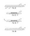
- FIGS. 3A-Cillustrate an embodiment of the movable support device in the resistive mode;
- FIG. 3Abeing a front elevation view;
- FIG. 3Ba side elevation view;
- FIG. 3Ca cross sectional view along line A-A;
- FIGS. 4A-Cillustrate an embodiment of the movable support device in the transportive mode; FIG. 4A being a front elevation view; FIG. 4B a side elevation view; and FIG. 4C a cross sectional view along line B-B; and
- FIG. 5Aillustrates a side view of the lever of one embodiment
- FIG. 5Billustrates a top view of the lever of FIG. 5A .
- FIG. 6Ais an exploded view of an embodiment having a displaceable second transportation mechanism
- FIG. 6Billustrates the device of FIG. 6A in the resistive mode where neither the first or second transportation mechanism are engaged
- FIG. 6Cillustrates a transportive mode where both the first and second transportation mechanisms are engaged
- FIG. 6Dillustrates a cross-section of FIG. 6B along A-A.
- FIG. 7A-Billustrate an embodiment having a drawer mechanism.
- FIG. 8illustrates an embodiment with a storage bin.
- a movable support device 100is described herein.
- the movable support device 100is a movable platform that may be used to support items such as small appliances and transport them back and forth, such as from under wall mounted cabinets so that the transported item can be accessed.
- the movable support device 100may be utilized to transport the coffee maker out from under a kitchen upper cabinet overhanging the countertop to access the filling door of the coffee maker.
- the movable support device 100includes a main body 110 .
- the main body 110includes a panel 111 and a sidewall 112 .
- the sidewall 112extends from the panel 111 and includes a void 115 adapted to receive at least a portion of a handle assembly 120 .
- the handle assembly 120includes a lever 121 and a first transportation mechanism 140 .
- the lever 121is hinged with respect to the main body 110 , allowing the lever 121 to rotate relative to the main body 110 .
- the lever 121is hingedly affixed to a bottom surface 116 of the panel 111 at a retention portion 122 of the lever 121 .
- the lever 121extends outward from the hinge 124 , such that an actuation portion 123 of the lever 121 extends through the void 115 of the sidewall 112 to be exterior to the main body 110 .
- the main body 110may include a stop 117 that interacts with the lever 121 to limit the range of motion of the lever 121 relative to the main body 110 .
- the lever 121 and the first transportation mechanism 140are connected, with the first transportation mechanism 140 positioned on the lever 121 to be engageable with a work surface (not shown) under the main body 110 .
- the first transportation mechanism 140may consist of one or more wheels, rollers, coasters, skids, or the like.
- the lever 121is freely hinged to the main body 110 with no bias other than that exerted by the mechanical relationship of the two components. It should be appreciated that due to the force exerted by the mass of the movable support device 100 , and any item placed thereon, the lever 121 will be rotated upwards towards the panel 111 and the resistive portion 160 of the main body 110 will be engaged with the work surface. Actuation of the handle assembly 120 , such as by pressing with a downward force sufficient to overcome the force exerted by the mass of the support device 100 and any item on it, causes the lever 121 to rotate downwards towards the work surface.
- the first transportation mechanism 140is associated with the lever 121 and moves with it such that the first transportation mechanism 140 engages the work surface.
- the lever 121has a shape that positions the first transportation mechanism 140 to contact the work surface upon actuation of the handle assembly 120 .
- the lever 121may have a generally “S”-shaped profile such that the first transportation mechanism 140 will be the closest portion of the handle assembly 120 to the work surface when in the resistive state. It should be appreciated that such a structure ensures that the first transportation mechanism 140 will engage the work surface due to actuation of the handle actuation portion 123 prior to the handle actuation portion 123 itself contacting the work surface and preventing further rotation of the lever 121 . In one embodiment, only a slight rotation of the lever 121 is necessary to engage the first transportation mechanism 140 with the work surface.
- a second transportation mechanism 150may also be provided to reduce the necessary force exerted in the transportation mode.
- the second transportation mechanism 150may be a low-friction portion of the sidewall 112 that is positioned to engage the work surface when in the transportative mode, i.e. when the main body 110 is slightly tilted.
- the second transportation mechanism 150may consists of one or more wheels, rollers, coasters, skids, or the like, which may connected with the main body 110 .
- FIG. 2Dillustrates an embodiment wherein the second transportation mechanism 150 comprises a plurality of rollers 151 , including roller covers 154 , that are positioned on axles 152 engageable with brackets 153 affixed to the bottom surface 116 of the panel 111 .
- the first transportation mechanism 140comprises at least one roller 141 consisting of a first roller cover 143 and a first roller 141 .
- the at least one roller 141may comprise two rollers 141 as illustrated in FIG. 1 , connected by an axle 144 .
- roller 141is attached to the lever 121 .
- the roller 141is lowered as the lever 121 is depressed, rotating away from the panel 111 towards the work surface.
- the first transportation mechanism 140includes the axle 144 affixed to the lever 121 .
- a handle cover 129is provided which is engageable with the lever 121 .
- the handle cover 129may comprise material selected for its ability to assist a user in gripping the lever 121 or material selected for comfort to a user.
- FIGS. 3A-Cillustrate the movable support device 100 of FIG. 1 in the resistive position.
- the handle assembly 120In the resistive position the handle assembly 120 is rotated towards the panel 111 .
- the weight of the item and the movable support device 100are sufficient to cause a resistance portion 160 to engage a work surface, such as a countertop or other surface upon which the movable support device 100 rests.
- a work surfacesuch as a countertop or other surface upon which the movable support device 100 rests.
- friction between a grip ring 161 and the work surfaceserves to resist movement (forward/backward/right/left) of the movable support device 100 .
- the handle assembly 120when the item on the movable support device 100 is to be moved, the handle assembly 120 may be actuated. Actuation of the handle assembly 120 results in movement of the first transportation mechanism 140 away from the main body 110 .
- the first transportation mechanism 140engages the work surface.
- the force exerted on the handle assembly 120acts to push the first transportation mechanism 140 against the work surface, which results in the main body 110 being displaced away from the work surface.
- This movement of the main body 110 due to the engagement of the transportation mechanism 140 with the work surfaceis sufficient to reduce the resistance provided by the resistance portion 160 , such as by lifting the resistance portion 160 from the work surface. This reduction of resistance allows the movable support device 100 to be transported.
- the force exerted on the handle assembly 120is such that the force vectors both are sufficient to engage the first transportation mechanism 140 with the work surface and to move the movable support device 100 , such as where a user pushes or pulls the caddy into the desired location.
- the handle mechanism 120is released, the first transportation mechanism 140 disengages from the work surface and the main body 110 approaches the work surface such that the resistance portion engages the work surface.
- the movable support deviceprovides a resistive mode and a transportive mode.
- the resistive modethe engagement of the resistance portion 160 to the work surface provides resistance against movement of the movable support device 100 .
- the transportive modethe engagement of the first transportation mechanism 140 with the work surface reduces the resistance of the movable support device in at least one direction.
- the movable support device 100may be used with a variety of small appliances or other items that need to be stored under the upper cabinets and pulled out for access including coffee makers, toasters, blenders, bread boxes and the like.
- the movable support device 100stays securely in place when the handle assembly 120 is not depressed.
- the appliancewill not move if accidentally bumped or, in the case of a coffee maker, it will not substantially move when the carafe is removed from the coffee maker. Further, when the movable support device 100 is moved, the first and second transportation mechanisms 140 , 150 enable a smooth motion so that items will not spill or tip over in transit.
- the movable support deviceincludes features for retaining the item placed on the device 100 .
- the main body 110may include a top surface 114 which is recessed in relation to the sidewall 112 , so that the sidewall 112 essentially forms a lip 113 or ridge about the top surface 114 , which at least partially retains an item placed on the support device 100 .
- the top surface 114may be of a material that aids in retaining the item placed on the support device 100 .
- the top surface 114may include a pattern or features which engage the item or may comprise a material that exhibits a high degree of friction, e.g. a nonskid surface such as a thermoplastic elastomer.
- a nonskid panel 180may be provided for placement on the top surface 114 .
- FIG. 1illustrates such an embodiment.
- the nonskid panel 180is disposed on the top surface 114 within the recess device by the top surface 114 and the lip 113 of the sidewall 112 .
- the nonskid panel 180may be physically affixed to the top surface such as via sonic welding, rivets, adhesive, clips, or the like. It may be desirable to be able to easily clean the nonskid panel 180 . Therefore, in one embodiment illustrated in FIG. 1 , the nonskid panel 180 is removably retained on the main body 110 by a cover 190 .
- the cover 190includes a sidewall 191 defining an opening through which the nonskid panel 180 is accessible when the cover 190 is placed on the main body 110 .
- the cover 190may be substantially the same shape, including providing a void 192 corresponding to the main body void 115 , such that the cover 190 substantially covers the sidewall 112 of the main body 110 .
- the cover 190may be in a snap-fit arrangement with the sidewall 112 of the main body 110 .
- the support deviceincludes a displaceable second transportation mechanism 150 .
- a connecting portion 201is attached to the body 110 at one end 202 and to the second transportation mechanism 150 at the other end 203 .
- the second transportation mechanism 150is also attached to a connecting rod 210 that extends from the first transportation mechanism to the second transportation mechanism 150 .
- a first end 212 of the connecting rod 210is connected to the first transportation mechanism and a second end 213 of the connecting rod 210 is connected to the second transportation mechanism 150 .
- the connecting rod 203is a solid component linking the relative position of the first transportation mechanism 140 and the second transportation mechanism 150 .
- the second transportation mechanism 150includes the axle 152 and the second end 203 of the connecting portion 201 and the second end 213 of the connecting rod 210 are connected to a roller 151 of the second transportation mechanism 150 at the axle 152 .
- the first transportation mechanism 140 and the second transportation mechanism 150each comprise a plurality of rollers 141 , 151 (illustrated as a pair).
- a respective right side roller 141 a of the first transportation mechanism 140is linked to a respective right side roller 151 a of the second transportation mechanism 150 a right side connecting rod 210 a .
- a respective left side roller 141 b of the first transportation mechanism 140is linked to a respective left side roller 151 b of the second transportation mechanism 150 a left side connecting rod 210 b .
- the connecting rod 310may be connected to other components of the handle assembly 120 , for example the lever 121 , rather than directly to the first transportation mechanism.
- the connecting rod 210transfers motion of the first transportation mechanism 140 , imparted, for example, by actuation of the lever 121 , to the second transportation mechanism 150 .
- the connecting portion 201facilitates a movement of the second transportation portion 150 away from the main body 120 .
- actuation of the lever 121 to lower the first transportation mechanism 140 to engage the surfacealso lowers the second transportation mechanism and engages the surface.
- FIG. 6Billustrates the device of FIG. 6A in the resistive mode where neither the first or second transportation mechanism are engaged.
- the main body 110rests on the surface.
- the main bodyis not supported by either the first transportation mechanism or the second transportation mechanism.
- the resistive portionengages the surface to resist movement of the support device.
- FIG. 6Cillustrates a transportive mode where both the first and second transportation mechanisms are engaged.
- the rollers 141 , 151 of the first and second transportation mechanismscan be seen supporting the main body 110 . This transportive mode allows the device to be moved via the rollers 141 , 151 .
- FIG. 6Dillustrates a cross-section of FIG. 6B along A-A.
- FIG. 6Aalso illustrates a mechanism for securing the rollers 141 , 151 to the axles 144 , 152 .
- a pin 171 in combination with snap rings 172 and 173may be used.
- FIG. 7A-Billustrate an embodiment having a drawer mechanism 300 .
- the drawer mechanism 300is provided as part of the main body 110 .
- the main body 110includes a main body top 310 that may have the top surface 114 thereon.
- the main body top 310is engageable with a main body bottom 320 .
- the main body bottom 320incldues the bottom surface 117 and the resistive portion 160 .
- the a void 115 in the main body bottom 320is provided for the handle assembly 120 to extend for actuation of the lever 121 .
- the first and second transportation mechanisms 140 , 150are engaged with the main body bottom 320 .
- the main body top 310 and main body bottom 320form chamber 302 therebetween, such as by side portions 311 of the main body top 310 spacing the top surface 114 from the main body bottom portion 320 .
- the side portions 311may be a part of the main body top 310 or the main body bottom 320 or separate components engageable with both the top 310 and the bottom 320 .
- One or more inserts or drawers 330are removably engageable with the chamber 302 .
- Draw guide mechanismssuch as known in the art may be utilized.
- FIG. 8illustrates an embodiment with a storage bin 401 .
- the main body 110may be configured to receive a bin 401 .
- the main bodymay be configured to receive various machines.
- the illustrated embodiment of FIG. 6Aincludes a retention post 270 .
- the retention postis configured to engage a corresponding feature of a stand-mixer type machine to secure the machine to the device 100 .
Landscapes
- Engineering & Computer Science (AREA)
- General Engineering & Computer Science (AREA)
- Food Science & Technology (AREA)
- Mechanical Engineering (AREA)
- Handcart (AREA)
Abstract
Description
Claims (20)
Priority Applications (1)
| Application Number | Priority Date | Filing Date | Title |
|---|---|---|---|
| US14/155,119US9192266B2 (en) | 2011-03-04 | 2014-01-14 | Movable support device |
Applications Claiming Priority (2)
| Application Number | Priority Date | Filing Date | Title |
|---|---|---|---|
| US13/041,271US8641060B2 (en) | 2011-03-04 | 2011-03-04 | Coffee caddy |
| US14/155,119US9192266B2 (en) | 2011-03-04 | 2014-01-14 | Movable support device |
Related Parent Applications (1)
| Application Number | Title | Priority Date | Filing Date |
|---|---|---|---|
| US13/041,271Continuation-In-PartUS8641060B2 (en) | 2011-03-04 | 2011-03-04 | Coffee caddy |
Publications (2)
| Publication Number | Publication Date |
|---|---|
| US20140183322A1 US20140183322A1 (en) | 2014-07-03 |
| US9192266B2true US9192266B2 (en) | 2015-11-24 |
Family
ID=51016031
Family Applications (1)
| Application Number | Title | Priority Date | Filing Date |
|---|---|---|---|
| US14/155,119ActiveUS9192266B2 (en) | 2011-03-04 | 2014-01-14 | Movable support device |
Country Status (1)
| Country | Link |
|---|---|
| US (1) | US9192266B2 (en) |
Cited By (21)
| Publication number | Priority date | Publication date | Assignee | Title |
|---|---|---|---|---|
| US9592845B2 (en)* | 2015-01-23 | 2017-03-14 | Dreamwell, Ltd. | Staging cart for transporting mattresses |
| US20170114563A1 (en)* | 2015-10-22 | 2017-04-27 | Yong He | Mobile base having telescopic foot pedal |
| US9839301B2 (en) | 2015-01-23 | 2017-12-12 | Dreamwell, Ltd. | Mattress manufacturing process and apparatus |
| US9862553B2 (en) | 2015-01-23 | 2018-01-09 | Dreamwell, Ltd. | Mattress manufacturing process and apparatus |
| USD822935S1 (en)* | 2016-12-01 | 2018-07-10 | Suncast Technologies, Llc | Container dolly |
| US10100969B1 (en)* | 2017-09-05 | 2018-10-16 | Linhai Baocheng Crafts Co., Ltd | Movable sunshade base |
| US10172474B2 (en) | 2015-01-23 | 2019-01-08 | Dreamwell, Ltd. | Mattress manufacturing process and apparatus |
| US10272611B2 (en) | 2015-01-23 | 2019-04-30 | Dreamwell, Ltd. | Mattress manufacturing process and apparatus |
| US10365638B2 (en) | 2015-01-23 | 2019-07-30 | Dreamwell, Ltd. | Scheduling process for automated mattress manufacturing |
| US10455950B2 (en) | 2015-01-23 | 2019-10-29 | Dreamwell, Ltd. | Mattress manufacturing process and apparatus |
| US10525557B2 (en) | 2015-01-23 | 2020-01-07 | Dreamwell, Ltd. | Automated mattress manufacturing process and apparatus |
| US10696540B2 (en) | 2015-04-15 | 2020-06-30 | Dreamwell, Ltd. | Coil string staging area apparatus and method |
| US10711481B2 (en)* | 2018-06-12 | 2020-07-14 | Zhejiang Yotrio Group Co., Ltd. | Removable sunshade base and sunshade |
| US11083339B1 (en)* | 2020-03-12 | 2021-08-10 | Nifty Home Products Inc. | Countertop appliance rolling tray |
| US11246452B2 (en) | 2020-04-17 | 2022-02-15 | Dc Drummond Products Inc. | Appliance base |
| US11246413B2 (en)* | 2017-06-09 | 2022-02-15 | Nikolai Hiorth | Furniture base and a piece of furniture comprising such a furniture base |
| US11457767B1 (en) | 2020-03-12 | 2022-10-04 | Nifty Home Products Inc. | Multi-directional movement countertop appliance rolling tray |
| US12114742B2 (en) | 2022-10-03 | 2024-10-15 | Mitchell J. Francis | Umbrella dolly |
| US12117178B2 (en) | 2022-10-03 | 2024-10-15 | Mitchell J. Francis | Heater dolly |
| US12150596B1 (en)* | 2023-11-09 | 2024-11-26 | Wendy Jestings | Appliance kitchen caddy with 360-degree wheels |
| US20250153755A1 (en)* | 2023-11-09 | 2025-05-15 | Wendy Jestings | Appliance kitchen caddy with 360-degree wheels |
Families Citing this family (6)
| Publication number | Priority date | Publication date | Assignee | Title |
|---|---|---|---|---|
| ES2529703B1 (en)* | 2014-12-16 | 2015-09-25 | Carlos MARTÍNEZ GIMENO | Anti-slip and anti-rolling object support |
| US10172457B2 (en)* | 2016-01-06 | 2019-01-08 | Lipper International, Inc. | Rollable drawer system and rollable appliance support system |
| US10051957B2 (en)* | 2016-01-06 | 2018-08-21 | Lipper International, Inc. | Rollable drawer system |
| US9961994B2 (en)* | 2016-03-04 | 2018-05-08 | Adrian Rivera | Coffee maker stand with drawer |
| USD823619S1 (en) | 2017-06-29 | 2018-07-24 | Lipper International, Inc. | Rollable appliance support system |
| US10427701B1 (en) | 2018-04-05 | 2019-10-01 | Duane S. Brede | Appliance stand and dolly |
Citations (64)
| Publication number | Priority date | Publication date | Assignee | Title |
|---|---|---|---|---|
| US1063620A (en)* | 1912-04-26 | 1913-06-03 | Narragansett Machine Company | Gymnasium apparatus. |
| US1200364A (en)* | 1916-04-22 | 1916-10-03 | James J Kane | Trunk-rack. |
| US1355173A (en)* | 1920-03-19 | 1920-10-12 | Henry A Shadel | Collapsible shipping-crate for live stock |
| US1956245A (en)* | 1930-05-08 | 1934-04-24 | Wepsco Steel Products Co | Truck |
| US2374982A (en)* | 1942-04-28 | 1945-05-01 | Davies Percy Hamilton | Hand truck |
| US2744710A (en)* | 1953-09-18 | 1956-05-08 | Gerosa Anthony | Movable support for containers |
| US2823924A (en)* | 1955-12-15 | 1958-02-18 | Southern States Equipment Corp | Retractable low friction means for movable bodies |
| US3178197A (en) | 1963-03-25 | 1965-04-13 | Boatner Carolyn | Roll along luggage |
| US3179438A (en)* | 1963-04-26 | 1965-04-20 | Charles Beseler Company | Toggle actuated caster arrangement |
| US3352568A (en)* | 1966-08-31 | 1967-11-14 | John C Ahlf | Extensible and retractable wheel assembly for luggage |
| US3404884A (en) | 1965-09-27 | 1968-10-08 | New American Co Inc | Balance beam adapter for gymnastic apparatus transporters |
| USD263820S (en) | 1980-02-20 | 1982-04-13 | Jefsteel Business Equipment Corp. | Business forms dolly |
| US4378191A (en)* | 1979-05-01 | 1983-03-29 | Masataro Sato | Cargo handling loader for pallets |
| US4417738A (en)* | 1980-12-22 | 1983-11-29 | Dynalectron Corporation | Retractable caster assembly having a lever in rolling engagement with a pressure plate |
| US4874182A (en)* | 1987-12-28 | 1989-10-17 | Wade Parker | Stroller apparatus for juvenile car seat |
| US4889352A (en) | 1988-09-06 | 1989-12-26 | Chamberlin Jr Louis D | Folding mechanic's creeper |
| US4902026A (en)* | 1989-02-16 | 1990-02-20 | Maldonado Robert L | Convertible car seat apparatus |
| USD327351S (en) | 1990-10-09 | 1992-06-23 | Dallas Tech Tools, Inc. | Wheeled tray with handles |
| US5127720A (en) | 1990-10-24 | 1992-07-07 | Florance Shultz | Lottery ticket tray |
| USD333899S (en) | 1990-10-19 | 1993-03-09 | Roberto Caceres | Recreational cart |
| US5299826A (en)* | 1992-03-20 | 1994-04-05 | Flowers Henry C | Multi-function cart |
| US5542346A (en)* | 1994-11-30 | 1996-08-06 | Shenk; Steve | Crumb collection tray |
| USD375658S (en) | 1994-12-29 | 1996-11-19 | Reichert Robert M | Float basket for edible goods |
| USD379701S (en) | 1992-06-25 | 1997-06-03 | Lorenzo Copeland, Sr. | Mobile paint tray |
| USD393386S (en) | 1996-12-06 | 1998-04-14 | Ian Pasalich | Shelving device |
| US5769436A (en)* | 1994-03-31 | 1998-06-23 | Androll | Movable device of the movable parasol stand type with concealed wheels |
| US5893571A (en) | 1998-08-04 | 1999-04-13 | Joseph Fanucchi | Wheeled automobile jack |
| USD435989S1 (en) | 1998-11-04 | 2001-01-09 | Hunt Thomas A | Desk mountable pull out shelf for storing paper sheets or the like |
| US6216994B1 (en)* | 1999-09-08 | 2001-04-17 | Jurapolly Industry Inc. | Slidable seat with brake device |
| US6240830B1 (en) | 1999-06-30 | 2001-06-05 | Joseph P. Goldston | Method and apparatus for relocating counter-top appliances |
| US20010035485A1 (en)* | 1999-03-24 | 2001-11-01 | Davis Mark E. | Rollable sports base |
| US6367748B1 (en)* | 2000-02-12 | 2002-04-09 | Solvisions Technologies Int'l | Apparatus for providing desktop mobility for desktop electronic devices |
| US6386560B2 (en)* | 2000-04-25 | 2002-05-14 | Joseph P. Calender | Dolly for large appliances |
| USD457364S1 (en) | 2001-04-27 | 2002-05-21 | Thomas M. Shea | Adjustable merchandise shelf extender |
| US6470793B1 (en)* | 2001-05-25 | 2002-10-29 | Sidney R. Vogt | Wheeled coffee maker device |
| USD467098S1 (en) | 2001-09-13 | 2002-12-17 | Merchandising Display Corp. | Display fixture component |
| US6607199B2 (en) | 2001-04-20 | 2003-08-19 | Rehrig Pacific Company | Tray and dolly assembly |
| US6656065B2 (en)* | 2002-01-16 | 2003-12-02 | Lifetime Products, Inc. | Wheel mounted adjustable roller support assembly for a basketball goal system |
| USD485700S1 (en) | 2002-05-30 | 2004-01-27 | Westmount Investments, Ltd. | Side table |
| US20040055913A1 (en) | 2002-09-24 | 2004-03-25 | Adrian Berry | Casing for an electric appliance and an electric appliance with such a casing |
| USD506588S1 (en) | 2003-07-28 | 2005-06-21 | Sylmark Holdings Limited | Tray for a dolly |
| US20050150395A1 (en) | 2004-01-12 | 2005-07-14 | Olekaibe Benson A. | Mobile chafing dish apparatus |
| US20060065126A1 (en) | 2004-09-24 | 2006-03-30 | Fianara International B.V. | Coffee maker having a height adjustable collecting tray |
| US7051853B2 (en)* | 2001-04-20 | 2006-05-30 | Deborah Brown | Convertible luggage device |
| US20060237026A1 (en) | 2005-04-20 | 2006-10-26 | Kerry Simester | Rolling tray for herbs for smoking |
| USD538988S1 (en) | 2004-05-06 | 2007-03-20 | Jordan Jr Thomas | Wheeled paint tray |
| US20080074020A1 (en) | 2006-09-21 | 2008-03-27 | Doubts James L | Slidable support system for portable storage containers |
| US20080251472A1 (en)* | 2007-04-16 | 2008-10-16 | Kasden Kenneth L | Cooking caddy |
| US20090020017A1 (en) | 2007-06-28 | 2009-01-22 | Tsann Kuen (China) Enterprise Co., Ltd. | Coffee Maker |
| US20090064450A1 (en) | 2007-09-08 | 2009-03-12 | Dyson Technology Limited | Surface treating appliance |
| USD589287S1 (en) | 2008-03-20 | 2009-03-31 | Metro Industries Inc. | Merchandising shelf with a raised mat |
| USD592897S1 (en) | 2008-03-20 | 2009-05-26 | Metro Industries Inc. | Mechandising shelf with a dropped mat |
| USD593347S1 (en) | 2008-04-04 | 2009-06-02 | Kilpatrick Jennifer A | Expandable shelf |
| USD594622S1 (en) | 2008-08-07 | 2009-06-16 | Devanand Kissun | Dolly |
| US7568667B1 (en)* | 2006-04-17 | 2009-08-04 | American Innovations Corporation | Mobile paint container support |
| US20090230647A1 (en)* | 2008-03-12 | 2009-09-17 | Kyocera Mita Corporation | Wheel supporting mechanism, post-processing apparatus, and image forming apparatus |
| US7770903B2 (en)* | 2007-02-26 | 2010-08-10 | Konstant Products, Inc. | Drawer type storage cart |
| US20110095497A1 (en)* | 2009-10-23 | 2011-04-28 | Hon Hai Precision Industry Co., Ltd. | Supporting device with wheels |
| US20120024329A1 (en)* | 2010-07-02 | 2012-02-02 | Oliver Joen-An Ma | Movable base with wheels deployable by cyclic driving assembly |
| US20120025050A1 (en)* | 2010-07-02 | 2012-02-02 | Oliver Joen-An Ma | Movable base with control surface |
| US8109525B2 (en)* | 2006-11-09 | 2012-02-07 | Linet Spol. S R.O. | Guiding wheel assembly, especially for a hospital bed |
| US20120186950A1 (en)* | 2009-07-31 | 2012-07-26 | Ishino Seisakusyo Co., Ltd. | Food and Drink Conveying Device |
| US20120223040A1 (en)* | 2011-03-04 | 2012-09-06 | Wilton Industries, Inc. | Coffee caddy |
| US8632045B2 (en)* | 2010-07-02 | 2014-01-21 | Oliver Joen-An Ma | Movable base with wheels deployable by reversible driving assembly |
- 2014
- 2014-01-14USUS14/155,119patent/US9192266B2/enactiveActive
Patent Citations (80)
| Publication number | Priority date | Publication date | Assignee | Title |
|---|---|---|---|---|
| US1063620A (en)* | 1912-04-26 | 1913-06-03 | Narragansett Machine Company | Gymnasium apparatus. |
| US1200364A (en)* | 1916-04-22 | 1916-10-03 | James J Kane | Trunk-rack. |
| US1355173A (en)* | 1920-03-19 | 1920-10-12 | Henry A Shadel | Collapsible shipping-crate for live stock |
| US1956245A (en)* | 1930-05-08 | 1934-04-24 | Wepsco Steel Products Co | Truck |
| US2374982A (en)* | 1942-04-28 | 1945-05-01 | Davies Percy Hamilton | Hand truck |
| US2744710A (en)* | 1953-09-18 | 1956-05-08 | Gerosa Anthony | Movable support for containers |
| US2823924A (en)* | 1955-12-15 | 1958-02-18 | Southern States Equipment Corp | Retractable low friction means for movable bodies |
| US3178197A (en) | 1963-03-25 | 1965-04-13 | Boatner Carolyn | Roll along luggage |
| US3179438A (en)* | 1963-04-26 | 1965-04-20 | Charles Beseler Company | Toggle actuated caster arrangement |
| US3404884A (en) | 1965-09-27 | 1968-10-08 | New American Co Inc | Balance beam adapter for gymnastic apparatus transporters |
| US3352568A (en)* | 1966-08-31 | 1967-11-14 | John C Ahlf | Extensible and retractable wheel assembly for luggage |
| US4378191A (en)* | 1979-05-01 | 1983-03-29 | Masataro Sato | Cargo handling loader for pallets |
| USD263820S (en) | 1980-02-20 | 1982-04-13 | Jefsteel Business Equipment Corp. | Business forms dolly |
| US4417738A (en)* | 1980-12-22 | 1983-11-29 | Dynalectron Corporation | Retractable caster assembly having a lever in rolling engagement with a pressure plate |
| US4874182A (en)* | 1987-12-28 | 1989-10-17 | Wade Parker | Stroller apparatus for juvenile car seat |
| US4889352A (en) | 1988-09-06 | 1989-12-26 | Chamberlin Jr Louis D | Folding mechanic's creeper |
| US4902026A (en)* | 1989-02-16 | 1990-02-20 | Maldonado Robert L | Convertible car seat apparatus |
| USD327351S (en) | 1990-10-09 | 1992-06-23 | Dallas Tech Tools, Inc. | Wheeled tray with handles |
| USD333899S (en) | 1990-10-19 | 1993-03-09 | Roberto Caceres | Recreational cart |
| US5127720A (en) | 1990-10-24 | 1992-07-07 | Florance Shultz | Lottery ticket tray |
| US5299826A (en)* | 1992-03-20 | 1994-04-05 | Flowers Henry C | Multi-function cart |
| USD379701S (en) | 1992-06-25 | 1997-06-03 | Lorenzo Copeland, Sr. | Mobile paint tray |
| US5769436A (en)* | 1994-03-31 | 1998-06-23 | Androll | Movable device of the movable parasol stand type with concealed wheels |
| US5542346A (en)* | 1994-11-30 | 1996-08-06 | Shenk; Steve | Crumb collection tray |
| USD375658S (en) | 1994-12-29 | 1996-11-19 | Reichert Robert M | Float basket for edible goods |
| USD393386S (en) | 1996-12-06 | 1998-04-14 | Ian Pasalich | Shelving device |
| US5893571A (en) | 1998-08-04 | 1999-04-13 | Joseph Fanucchi | Wheeled automobile jack |
| USD435989S1 (en) | 1998-11-04 | 2001-01-09 | Hunt Thomas A | Desk mountable pull out shelf for storing paper sheets or the like |
| US6412746B2 (en)* | 1999-03-24 | 2002-07-02 | Huffy Corporation | Rollable sports base |
| US6427963B1 (en)* | 1999-03-24 | 2002-08-06 | Huffy Corporation | Rollable sports base |
| US20010035485A1 (en)* | 1999-03-24 | 2001-11-01 | Davis Mark E. | Rollable sports base |
| US20010035480A1 (en)* | 1999-03-24 | 2001-11-01 | Davis Mark E. | Rollable sports base |
| US20010035481A1 (en)* | 1999-03-24 | 2001-11-01 | Davis Mark E. | Rollable sports base |
| US6554243B2 (en)* | 1999-03-24 | 2003-04-29 | Huffy Corporation | Rollable sports base |
| US6412747B2 (en)* | 1999-03-24 | 2002-07-02 | Huffy Corporation | Rollable sports base |
| US6405990B2 (en)* | 1999-03-24 | 2002-06-18 | Huffy Corporation | Rollable sports base |
| US6405989B2 (en)* | 1999-03-24 | 2002-06-18 | Huffy Corporation | Rollable sports base |
| US6410068B2 (en) | 1999-06-30 | 2002-06-25 | Joseph P. Goldston | Method for brewing coffee using a relocatable coffee maker |
| US6240830B1 (en) | 1999-06-30 | 2001-06-05 | Joseph P. Goldston | Method and apparatus for relocating counter-top appliances |
| US6216994B1 (en)* | 1999-09-08 | 2001-04-17 | Jurapolly Industry Inc. | Slidable seat with brake device |
| US6691961B2 (en)* | 2000-02-12 | 2004-02-17 | Solvisions Technologies Int'l | Apparatus for providing desktop mobility for desktop electronic devices |
| US7137603B2 (en)* | 2000-02-12 | 2006-11-21 | Solvisions Technologies International | Apparatus for providing desktop mobility for desktop electronic devices |
| US6367748B1 (en)* | 2000-02-12 | 2002-04-09 | Solvisions Technologies Int'l | Apparatus for providing desktop mobility for desktop electronic devices |
| US6386560B2 (en)* | 2000-04-25 | 2002-05-14 | Joseph P. Calender | Dolly for large appliances |
| US7104553B2 (en) | 2001-04-20 | 2006-09-12 | Rehrig Pacific Company | Tray and dolly assembly |
| US7051853B2 (en)* | 2001-04-20 | 2006-05-30 | Deborah Brown | Convertible luggage device |
| US6607199B2 (en) | 2001-04-20 | 2003-08-19 | Rehrig Pacific Company | Tray and dolly assembly |
| US6857642B2 (en) | 2001-04-20 | 2005-02-22 | Rehrig Pacific Company | Tray and dolly assembly |
| USD457364S1 (en) | 2001-04-27 | 2002-05-21 | Thomas M. Shea | Adjustable merchandise shelf extender |
| US6470793B1 (en)* | 2001-05-25 | 2002-10-29 | Sidney R. Vogt | Wheeled coffee maker device |
| USD467098S1 (en) | 2001-09-13 | 2002-12-17 | Merchandising Display Corp. | Display fixture component |
| US6656065B2 (en)* | 2002-01-16 | 2003-12-02 | Lifetime Products, Inc. | Wheel mounted adjustable roller support assembly for a basketball goal system |
| USD485700S1 (en) | 2002-05-30 | 2004-01-27 | Westmount Investments, Ltd. | Side table |
| US20040055913A1 (en) | 2002-09-24 | 2004-03-25 | Adrian Berry | Casing for an electric appliance and an electric appliance with such a casing |
| USD506588S1 (en) | 2003-07-28 | 2005-06-21 | Sylmark Holdings Limited | Tray for a dolly |
| US20050150395A1 (en) | 2004-01-12 | 2005-07-14 | Olekaibe Benson A. | Mobile chafing dish apparatus |
| USD538988S1 (en) | 2004-05-06 | 2007-03-20 | Jordan Jr Thomas | Wheeled paint tray |
| US20060065126A1 (en) | 2004-09-24 | 2006-03-30 | Fianara International B.V. | Coffee maker having a height adjustable collecting tray |
| US20060237026A1 (en) | 2005-04-20 | 2006-10-26 | Kerry Simester | Rolling tray for herbs for smoking |
| US7568667B1 (en)* | 2006-04-17 | 2009-08-04 | American Innovations Corporation | Mobile paint container support |
| US20080074020A1 (en) | 2006-09-21 | 2008-03-27 | Doubts James L | Slidable support system for portable storage containers |
| US8109525B2 (en)* | 2006-11-09 | 2012-02-07 | Linet Spol. S R.O. | Guiding wheel assembly, especially for a hospital bed |
| US7770903B2 (en)* | 2007-02-26 | 2010-08-10 | Konstant Products, Inc. | Drawer type storage cart |
| US20080251472A1 (en)* | 2007-04-16 | 2008-10-16 | Kasden Kenneth L | Cooking caddy |
| US20090020017A1 (en) | 2007-06-28 | 2009-01-22 | Tsann Kuen (China) Enterprise Co., Ltd. | Coffee Maker |
| US20090064450A1 (en) | 2007-09-08 | 2009-03-12 | Dyson Technology Limited | Surface treating appliance |
| US20090230647A1 (en)* | 2008-03-12 | 2009-09-17 | Kyocera Mita Corporation | Wheel supporting mechanism, post-processing apparatus, and image forming apparatus |
| USD589287S1 (en) | 2008-03-20 | 2009-03-31 | Metro Industries Inc. | Merchandising shelf with a raised mat |
| USD592897S1 (en) | 2008-03-20 | 2009-05-26 | Metro Industries Inc. | Mechandising shelf with a dropped mat |
| USD593347S1 (en) | 2008-04-04 | 2009-06-02 | Kilpatrick Jennifer A | Expandable shelf |
| USD594622S1 (en) | 2008-08-07 | 2009-06-16 | Devanand Kissun | Dolly |
| US20120186950A1 (en)* | 2009-07-31 | 2012-07-26 | Ishino Seisakusyo Co., Ltd. | Food and Drink Conveying Device |
| US20110095497A1 (en)* | 2009-10-23 | 2011-04-28 | Hon Hai Precision Industry Co., Ltd. | Supporting device with wheels |
| US8292309B2 (en)* | 2009-10-23 | 2012-10-23 | Hon Hai Precision Industry Co., Ltd. | Supporting device with wheels |
| US20120025050A1 (en)* | 2010-07-02 | 2012-02-02 | Oliver Joen-An Ma | Movable base with control surface |
| US20120024329A1 (en)* | 2010-07-02 | 2012-02-02 | Oliver Joen-An Ma | Movable base with wheels deployable by cyclic driving assembly |
| US8632045B2 (en)* | 2010-07-02 | 2014-01-21 | Oliver Joen-An Ma | Movable base with wheels deployable by reversible driving assembly |
| US8657246B2 (en)* | 2010-07-02 | 2014-02-25 | Oliver Joen-An Ma | Movable base with control surface |
| US20120223040A1 (en)* | 2011-03-04 | 2012-09-06 | Wilton Industries, Inc. | Coffee caddy |
| US8641060B2 (en)* | 2011-03-04 | 2014-02-04 | Wilton Industries, Inc. | Coffee caddy |
Non-Patent Citations (3)
| Title |
|---|
| Notice of Allowance for U.S. Appl. No. 13/041,271 dated Sep. 27, 2013, 15 pages. |
| Office Action for U.S. Appl. No. 13/041,271 dated Jun. 20, 2013, 10 pages. |
| Pull Out Coffee Maker Caddy (Item #32920) , "Handy Caddy", 2 pages. |
Cited By (23)
| Publication number | Priority date | Publication date | Assignee | Title |
|---|---|---|---|---|
| US10365638B2 (en) | 2015-01-23 | 2019-07-30 | Dreamwell, Ltd. | Scheduling process for automated mattress manufacturing |
| US9839301B2 (en) | 2015-01-23 | 2017-12-12 | Dreamwell, Ltd. | Mattress manufacturing process and apparatus |
| US9862553B2 (en) | 2015-01-23 | 2018-01-09 | Dreamwell, Ltd. | Mattress manufacturing process and apparatus |
| US10525557B2 (en) | 2015-01-23 | 2020-01-07 | Dreamwell, Ltd. | Automated mattress manufacturing process and apparatus |
| US9592845B2 (en)* | 2015-01-23 | 2017-03-14 | Dreamwell, Ltd. | Staging cart for transporting mattresses |
| US10455950B2 (en) | 2015-01-23 | 2019-10-29 | Dreamwell, Ltd. | Mattress manufacturing process and apparatus |
| US10172474B2 (en) | 2015-01-23 | 2019-01-08 | Dreamwell, Ltd. | Mattress manufacturing process and apparatus |
| US10272611B2 (en) | 2015-01-23 | 2019-04-30 | Dreamwell, Ltd. | Mattress manufacturing process and apparatus |
| US10696540B2 (en) | 2015-04-15 | 2020-06-30 | Dreamwell, Ltd. | Coil string staging area apparatus and method |
| US10017955B2 (en)* | 2015-10-22 | 2018-07-10 | Yong He | Mobile base having telescopic foot pedal |
| US20170114563A1 (en)* | 2015-10-22 | 2017-04-27 | Yong He | Mobile base having telescopic foot pedal |
| USD822935S1 (en)* | 2016-12-01 | 2018-07-10 | Suncast Technologies, Llc | Container dolly |
| US11246413B2 (en)* | 2017-06-09 | 2022-02-15 | Nikolai Hiorth | Furniture base and a piece of furniture comprising such a furniture base |
| US10100969B1 (en)* | 2017-09-05 | 2018-10-16 | Linhai Baocheng Crafts Co., Ltd | Movable sunshade base |
| US10711481B2 (en)* | 2018-06-12 | 2020-07-14 | Zhejiang Yotrio Group Co., Ltd. | Removable sunshade base and sunshade |
| US11083339B1 (en)* | 2020-03-12 | 2021-08-10 | Nifty Home Products Inc. | Countertop appliance rolling tray |
| US11457767B1 (en) | 2020-03-12 | 2022-10-04 | Nifty Home Products Inc. | Multi-directional movement countertop appliance rolling tray |
| US11246452B2 (en) | 2020-04-17 | 2022-02-15 | Dc Drummond Products Inc. | Appliance base |
| US12114742B2 (en) | 2022-10-03 | 2024-10-15 | Mitchell J. Francis | Umbrella dolly |
| US12117178B2 (en) | 2022-10-03 | 2024-10-15 | Mitchell J. Francis | Heater dolly |
| US12222109B1 (en) | 2022-10-03 | 2025-02-11 | Mitchell J. Francis | Heater dolly |
| US12150596B1 (en)* | 2023-11-09 | 2024-11-26 | Wendy Jestings | Appliance kitchen caddy with 360-degree wheels |
| US20250153755A1 (en)* | 2023-11-09 | 2025-05-15 | Wendy Jestings | Appliance kitchen caddy with 360-degree wheels |
Also Published As
| Publication number | Publication date |
|---|---|
| US20140183322A1 (en) | 2014-07-03 |
Similar Documents
| Publication | Publication Date | Title |
|---|---|---|
| US9192266B2 (en) | Movable support device | |
| US8641060B2 (en) | Coffee caddy | |
| US9055813B2 (en) | Pull-down shelf for furniture | |
| EP3189756B1 (en) | Rollable drawer system | |
| US8926031B2 (en) | Under cabinet drawer assembly | |
| US7014058B2 (en) | Selectively adjustable and couplable container | |
| JP5199144B2 (en) | Storage | |
| EP2235452B1 (en) | A cooling device | |
| KR20100091907A (en) | Storage | |
| US20080067139A1 (en) | Over the Door Storage Assembly | |
| JP7126127B2 (en) | counter unit | |
| JP2010148788A (en) | Frying pan rack | |
| JP4635995B2 (en) | Wagon stool | |
| US11412895B2 (en) | Quick access storage container system | |
| JP2008178534A (en) | Lid dispenser | |
| KR200210917Y1 (en) | The moving cart for supplying foods | |
| KR200458821Y1 (en) | Multypurpose spice chest | |
| KR20160122965A (en) | A free sink change in the position of the cupboard | |
| JP2024162620A (en) | furniture | |
| JP6234062B2 (en) | Kitchen sink | |
| JP4544137B2 (en) | Wagon on casters | |
| KR20180064176A (en) | Kitchen utensils | |
| KR102062083B1 (en) | Trays with cup holders | |
| JP6720445B2 (en) | Open storage container | |
| KR200282729Y1 (en) | Electric rice cooker with drawer for receiving dishs and the like |
Legal Events
| Date | Code | Title | Description |
|---|---|---|---|
| AS | Assignment | Owner name:WILTON INDUSTRIES, INC., ILLINOIS Free format text:ASSIGNMENT OF ASSIGNORS INTEREST;ASSIGNORS:STARR, DAVID;MCFADDEN, KEVIN;CHIU, JEFFREY;AND OTHERS;SIGNING DATES FROM 20140331 TO 20140401;REEL/FRAME:032888/0462 | |
| AS | Assignment | Owner name:DEUTSCHE BANK TRUST COMPANY AMERICAS, AS COLLATERA Free format text:SECURITY INTEREST;ASSIGNOR:WILTON INDUSTRIES, INC.;REEL/FRAME:036923/0757 Effective date:20140808 Owner name:DEUTSCHE BANK TRUST COMPANY AMERICAS, AS COLLATERA Free format text:SECURITY INTEREST;ASSIGNOR:WILTON INDUSTRIES, INC.;REEL/FRAME:036923/0692 Effective date:20140808 | |
| STCF | Information on status: patent grant | Free format text:PATENTED CASE | |
| AS | Assignment | Owner name:WELLS FARGO BANK, NATIONAL ASSOCIATION, ILLINOIS Free format text:SECURITY AGREEMENT;ASSIGNOR:WILTON INDUSTRIES, INC.;REEL/FRAME:041187/0195 Effective date:20161222 | |
| AS | Assignment | Owner name:WILTON INDUSTRIES, INC., ILLINOIS Free format text:RELEASE BY SECURED PARTY;ASSIGNOR:DEUTSCHE BANK TRUST COMPANY AMERICAS, AS COLLATERAL AGENT;REEL/FRAME:041210/0331 Effective date:20161222 | |
| AS | Assignment | Owner name:WILTON INDUSTRIES, INC., ILLINOIS Free format text:ABL PARTIAL TERMINATION AND RELEASE OF SECURITY INTEREST;ASSIGNOR:DEUTSCHE BANK TRUST COMPANY AMERICAS;REEL/FRAME:041390/0978 Effective date:20161207 Owner name:WILTON INDUSTRIES, INC., ILLINOIS Free format text:TERM LOAN PARTIAL TERMINATION AND RELEASE OF SECURITY INTEREST;ASSIGNOR:DEUTSCHE BANK TRUST COMPANY AMERICAS;REEL/FRAME:041390/0890 Effective date:20161207 | |
| AS | Assignment | Owner name:LIFETIME BRANDS, INC., NEW YORK Free format text:ASSIGNMENT OF ASSIGNORS INTEREST;ASSIGNOR:WILTON INDUSTRIES INC.;REEL/FRAME:041565/0346 Effective date:20161005 | |
| AS | Assignment | Owner name:WILTON INDUSTRIES, INC., ILLINOIS Free format text:RELEASE BY SECURED PARTY;ASSIGNOR:DEUTSCHE BANK TRUST COMPANY AMERICAS, AS COLLATERAL AGENT;REEL/FRAME:042465/0894 Effective date:20170512 | |
| AS | Assignment | Owner name:HPS INVESTMENT PARTNERS, LLC, NEW YORK Free format text:SECURITY INTEREST;ASSIGNOR:WILTON INDUSTRIES, INC.;REEL/FRAME:042478/0316 Effective date:20170515 | |
| AS | Assignment | Owner name:U.S. BANK NATIONAL ASSOCIATION, NORTH CAROLINA Free format text:SECURITY INTEREST;ASSIGNOR:WILTON INDUSTRIES, INC.;REEL/FRAME:042662/0830 Effective date:20170515 | |
| AS | Assignment | Owner name:JPMORGAN CHASE BANK, N.A., AS ADMINISTRATIVE AGENT, ILLINOIS Free format text:SECURITY INTEREST;ASSIGNOR:LIFETIME BRANDS, INC.;REEL/FRAME:045498/0033 Effective date:20180302 Owner name:JPMORGAN CHASE BANK, N.A., AS ADMINISTRATIVE AGENT, NEW YORK Free format text:SECURITY INTEREST;ASSIGNOR:LIFETIME BRANDS, INC.;REEL/FRAME:045498/0001 Effective date:20180302 Owner name:JPMORGAN CHASE BANK, N.A., AS ADMINISTRATIVE AGENT Free format text:SECURITY INTEREST;ASSIGNOR:LIFETIME BRANDS, INC.;REEL/FRAME:045498/0001 Effective date:20180302 Owner name:JPMORGAN CHASE BANK, N.A., AS ADMINISTRATIVE AGENT Free format text:SECURITY INTEREST;ASSIGNOR:LIFETIME BRANDS, INC.;REEL/FRAME:045498/0033 Effective date:20180302 | |
| MAFP | Maintenance fee payment | Free format text:PAYMENT OF MAINTENANCE FEE, 4TH YEAR, LARGE ENTITY (ORIGINAL EVENT CODE: M1551); ENTITY STATUS OF PATENT OWNER: LARGE ENTITY Year of fee payment:4 | |
| MAFP | Maintenance fee payment | Free format text:PAYMENT OF MAINTENANCE FEE, 8TH YEAR, LARGE ENTITY (ORIGINAL EVENT CODE: M1552); ENTITY STATUS OF PATENT OWNER: LARGE ENTITY Year of fee payment:8 |