US9189022B2 - Wearable glove electronic device - Google Patents
Wearable glove electronic deviceDownload PDFInfo
- Publication number
- US9189022B2 US9189022B2US14/079,074US201314079074AUS9189022B2US 9189022 B2US9189022 B2US 9189022B2US 201314079074 AUS201314079074 AUS 201314079074AUS 9189022 B2US9189022 B2US 9189022B2
- Authority
- US
- United States
- Prior art keywords
- electronic device
- peripherals
- glove
- glove electronic
- information
- Prior art date
- Legal status (The legal status is an assumption and is not a legal conclusion. Google has not performed a legal analysis and makes no representation as to the accuracy of the status listed.)
- Active, expires
Links
Images


Classifications
- G—PHYSICS
- G06—COMPUTING OR CALCULATING; COUNTING
- G06F—ELECTRIC DIGITAL DATA PROCESSING
- G06F1/00—Details not covered by groups G06F3/00 - G06F13/00 and G06F21/00
- G06F1/16—Constructional details or arrangements
- G06F1/1613—Constructional details or arrangements for portable computers
- G06F1/163—Wearable computers, e.g. on a belt
- A—HUMAN NECESSITIES
- A41—WEARING APPAREL
- A41D—OUTERWEAR; PROTECTIVE GARMENTS; ACCESSORIES
- A41D19/00—Gloves
- A41D19/0024—Gloves with accessories
- G—PHYSICS
- G06—COMPUTING OR CALCULATING; COUNTING
- G06F—ELECTRIC DIGITAL DATA PROCESSING
- G06F3/00—Input arrangements for transferring data to be processed into a form capable of being handled by the computer; Output arrangements for transferring data from processing unit to output unit, e.g. interface arrangements
- G06F3/01—Input arrangements or combined input and output arrangements for interaction between user and computer
- G06F3/011—Arrangements for interaction with the human body, e.g. for user immersion in virtual reality
- G06F3/014—Hand-worn input/output arrangements, e.g. data gloves
Definitions
- Wearable computersare typically miniature electronic devices worn by a user. These devices enable interactions with users and capture data based on user interactions and movements. However, the information processed by wearable computers or other types of computers is typically unrelated to the ordinary movements of a hand performing a task.
- a computer/scannermay be used to scan the address separate from hand movements, such as lifting of the package. Accordingly, the delivery person must perform separate actions to, for example, move the package and scan the package.
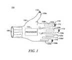
- FIG. 1is a block diagram of a glove electronic device used in accordance with some embodiments.
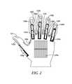
- FIG. 2further illustrates the sensors used on the glove electronic device in accordance with some embodiments.
- FIG. 3is a flow diagram of operations used in accordance with some embodiments.
- Some embodimentsare directed to apparatuses and methods for processing information based on movements of a glove electronic device.
- the glove electronic deviceincludes a plurality of peripherals, each of which is affixed to an adhesive cover and attachable to a location in at least one of finger portions, a wrist portion and a hand portion of the glove electronic device. Configuration of the plurality of peripherals on the glove electronic device is adaptable during use of the glove electronic device.
- the devicealso includes a transceiver for sending information captured by one or more of the plurality of peripherals and for transmitting information to one or more of the plurality of peripherals.
- the devicefurther includes a processor configured to operate one or more of the plurality of peripherals responsive to a movement associated with the glove electronic device.
- FIG. 1is a block diagram of a glove device used in accordance with some embodiments.
- Glove device 100(also referred to as a glove electronic device) may include a hand portion 104 , a wrist portion 106 and finger portions 108 (i.e., 108 a - 108 e ), such that glove device 100 may be configured in the shape of a hand.
- Glove device 100may be made out of materials, for example, plastic, capable of housing one or more electronic components.
- the electronic components of glove device 100may include a communications unit (not shown) coupled to a processing unit (also referred to simply as a processor) 114 .
- Glove device 100may also include one or more peripherals, each of which is configured to detect, receive, and/or transmit data based on movements of glove device 100 .
- the configuration of one or more of the peripherals in glove device 100may be adaptable based on use of glove device 100 .
- one or more of the peripheralsmay be added to or removed from glove device 100 using, for example, removable skin.
- each peripheralmay be affixed to an adhesive cover (also referred to as a removable skin) that can be attached to a section of glove device 100 .
- the removable skin to which each peripheral is affixedmay be attached and reattached to the same or different section of glove device 100 during use of glove device 100 . Therefore, the configuration of the peripherals on the glove electronic device is adaptable during use of the glove electronic device 100 .
- Non-limiting examples of peripherals that may be included in glove device 100may be a sensing computer 110 configured to detect environmental conditions, a radio frequency identifier (RFID) reader 112 configured to scan RFID tags, a recording device (not shown) such as a camera, one or more sensors 120 (i.e., 120 a - 102 d ), one or more active emitters 116 and/or a lighting source 118 , each coupled to be in communication with processing unit 114 and capable of being activated by processing unit 114 or another source.
- RFIDradio frequency identifier
- Glove device 100may also include an input unit (e.g., keypad, pointing device, etc.), an output transducer unit (e.g., speaker), an input transducer unit (e.g., a microphone) (MIC), and a display screen, each coupled to be in communication with the processing unit 114 and capable of being activated by processing unit 114 or another source.
- the speaker/microphone configurationmay be configured with Push-To-Talk capability, Voice over IP (VoIP) capability or may be configured to perform other telephony related tasks. It should be noted that the placements of the components on glove device 100 as shown in the figures are only illustrative.
- the communications unitmay include a radio frequency (RF) interface configurable to communicate with network components, and other user equipment within its communication range.
- the communications unitmay include one or more broadband and/or narrowband transceivers, such as an Long Term Evolution (LTE) transceiver, a Third Generation (3G) (3GGP or 3GGP2) transceiver, an Association of Public Safety Communication Officials (APCO) Project 25 (P25) transceiver, a Digital Mobile Radio (DMR) transceiver, a Terrestrial Trunked Radio (TETRA) transceiver, a Worldwide Interoperability for Microwave Access (WiMAX) transceiver perhaps operating in accordance with an IEEE 802.16 standard, and/or other similar type of wireless transceiver configurable to communicate via a wireless network for infrastructure communications.
- LTELong Term Evolution
- 3GGP or 3GGP2Third Generation
- APNAssociation of Public Safety Communication Officials
- DMRDigital Mobile Radio
- TETRATerrestrial Trunked Radio
- the communications unitmay also include one or more local area network or personal area network transceivers such as wireless local area network transceiver perhaps operating in accordance with an IEEE 802.11 standard (e.g., 802.11a, 802.11b, 802.11g), or a Bluetooth transceiver.
- IEEE 802.11 standarde.g., 802.11a, 802.11b, 802.11g
- Bluetooth transceivere.g., Bluetooth transceiver.
- Processing unit 114may include an encoder/decoder for encoding and decoding voice, data, control, or other signals that may be transmitted or received by glove device 100 .
- Processing unit 114may further include a digital signal processor (DSP) coupled to the speaker and the microphone for operating on audio signals received by glove device 100 .
- DSPdigital signal processor
- Processing unit 114may also include a character read-only memory (ROM) for storing code for decoding or encoding data such as control, request, or instruction messages, channel change messages, and/or data or voice messages that may be transmitted or received by glove device 100 .
- Processing unit 114may also be communicatively coupled to a static memory 124 configured store operating code associated with processor 114 .
- Processing unit 114may further include or be communicatively coupled to a tracking module for tracking glove device 100 .
- processing unit 114may further include or be communicatively coupled to a satellite-based tracking sensor such as global positioning system (GPS) sensor, dead-reckoning sensor, indoor sensor nodes, wireless triangulation sensor, accelerometer-based positioning sensor and/or a radar detector .
- GPSglobal positioning system
- Processing unit 114may also be connected to a power system including, for example, a battery, solar panel(s) and/or inductive charging components installed on knuckle plates on one or more of the finger portions 108 , on the wrist portion of glove device 106 , or back of the hand portion 104 of glove device 100 .
- FIG. 2further illustrates the sensors used on the glove device in accordance with some embodiments.
- FIG. 2shows that the finger portions of glove device 100 may include other sensors in addition to sensors 120 a - 120 d shown in FIG. 1 .
- the positions of sensors 120 a - 102 d on glove device 100is different in FIG. 1 and FIG. 2 to illustrate that the position each of the sensors may be changed, depending on use of the glove electronic device 100 .
- the thumb portion of glove device 100includes a reading sensor 121 (also referred to as an identity reader) for reading identifying information such as a fingerprint or other identifying information associated with a user.
- Sensor 121may be used, for example, in security applications to verify a user identity.
- Each finger portion of glove device 100also includes two sensors (i.e., 120 a - 120 n ), although any number of sensors may be included in one or more of the finger portions of glove device 100 .
- One or more sensorsmay also be affixed to other sections of glove device 100 as shown, for example, with sensor 120 o which is affixed to processor 114 .
- Sensors 120 and 121may be flexible sensors that can be manipulated to conform to various shapes and so that sensors 120 and 121 can be incorporated into one or more sections of glove device 100 .
- one or more of sensors 120 and 121may be added to or removed from glove device 100 during use of glove device 100 .
- the configuration of one or more of sensors 120 and 121 in glove devicemay be adaptable based on use of glove device 100 .
- each of sensors 120 and 121may be affixed to a removable skin that can be attached and reattached to the same or different section of glove device 100 during use of glove device 100 .
- Each of sensors 120 and 121may be activated by processing unit 114 in order for the activated sensor to detect, receive, and/or transmit data based on movements of glove device 100 .
- a sensing computerWhen activated, a sensing computer is configured to detect environmental information, for example, the ambient temperature, air quality, the smell of alcohol, or gases based on information provided by one or more sensor 120 .
- Sensors 120may include a precision gas sensor that may be used, for example, in detecting air quality, breath analysis, carbon monoxide monitoring, or alcohol testing; a reducing gas sensor that may be used, for example, in methane, propane, or natural gas detection; an oxidizing gas sensor that may be used, for example, in ozone and in chlorine leaks detection; a non-contact thermometer that may be used, for example, in non-contact thermometry, thermal leak detection, energy audits and/or energy diagnostics; a humidity sensor that may be used, for example, in weather or heat index detection or used in incubators, storage or refrigerator crispers; a temperature sensor that may be used in a variety of ambient temperature monitoring applications; a light sensor that may be used in solar monitoring, indoor lighting, light intensity; a color sensor that may be used in automation projects
- glove device 100may include the sensing computer 110 and RFID reader 112 configured to read RFID tags and/or 1-dimensional or 2-dimensional barcodes.
- Glove device 100may also include lighting source 118 that may be used to create characters or signs depending on movements associated with glove device 110 .
- the lighting source 118may be, for example, LED lights that may be used to create predefined signs or symbols when certain gestures are made using glove device 100 .
- lighting source 118may create a stop sign in the palm section of glove device when glove device is raised as shown in FIG. 2 .
- Lighting source 114may also be used to outline information being inputted to glove device 100 .
- lighting source 118may be operatively coupled with the speaker/microphone configuration such that a call may be made when a button (not shown) on glove device 100 is activated.
- a buttonnot shown
- gestures in the form of numbersmay be made with movements of one or more of the finger portions 108 of glove device 100 and lighting source 118 may display or outline information associated with the movements of glove device 100 .
- lighting sourcemay display information on a surface such as the ground, a table or in the air. In addition to displaying the information, lighting source 118 may transmit the information to processing unit 114 .
- lighting source 118may outline the numbers to be dialed, for example, the numbers “911” created with gestures from a finger portion 108 of the glove device 100 .
- lighting source 118may transmit the information to one or more components of glove device 100 for further processing. For instance, lighting source 118 may submit the outlined numbers to processing unit 114 or to a communicatively coupled communication device in order for the device to dial “911”.
- One or more emitters 116may be configured to share data collected by one or more sensors 120 and 121 or other components of glove device 100 via, for example, wireless pairing contact.
- emitters 116may transmit data from glove device 100 when the glove device 100 is paired with another device using, for example, Bluetooth protocol.
- Emitters 116may also transmit data from glove device 100 when the glove device 100 is paired with a smart tag, Near Field Communication (NFC) tag or any wireless sticker with intelligence.
- data from glove device 100may be transmitted via a wired connection, such as a USB connection between glove device 100 and another device.
- Glove device 100may be paired with another electronic device being worn by the user of glove device 100 .
- glove device 100may be paired with a headset being worn by the user of glove device by, for example, Bluetooth pairing between glove device 100 and the headset.
- a display screen(not shown) may be embedded in a region of the hand portion, for example, to show result from one or more of the peripherals.
- processing unit 114determines which sensors 120 and 121 and/or other peripherals are to be enabled and which sensors 120 and 121 and/or other peripherals are to be deactivated. Therefore, depending on the operating environment, processing unit may selectively activate or deactivate one or more peripherals. Subsequent to being powered on, glove device 100 may obtain data via the one or more activated peripherals based on movements of glove device 100 . For example, an activated card reader sensor 120 f may read credit card information when the credit card is passed between the index finger and the middle finger portions of glove device 100 . In other examples, using one or more peripherals, glove device 100 may make phone calls, scan information, operate a flashlight, record audio, and/or generate symbols based on the movements associated one or more portions of glove device 100 .
- a policeis wearing glove device 100 that includes an activated speed detecting sensor, a card reader, and one or more other sensors in the finger portions.
- the policemay determine a driver's speed simply by placing his hand wearing glove device 100 in the direction of incoming traffic.
- the policemay also read a driver's license simply by moving a reading sensor in glove device 100 over the license or by picking up the license with glove device 100 . In potential harmful situations, this may enable the police to keep one hand on his weapon while retrieving vital information with glove device 100 .
- one or more activated sensors in glove device 100may capture other environmental information, for example, the speed with which a weapon is fired, the ambient temperature, or the presence of a substance such as alcohol.
- Each of the activated sensorsmay send the captured speed to the processor 114 and/or display the speed on a display device. Therefore, the police may obtain necessary information with ordinary hand movements and without using additional processor such as radar guns.
- glove device 100may be used as a surgical tool that is capable of capturing key health metrics and that may be used in diagnosing certain diseases.
- Metrics for healthcould include, for example, blood pressure readings, respiratory rate, temperature, and precision of incisions.
- One or more of the sensors in glove device 100may be used, for example, to sample blood and other human fluids and in drug testing.
- glove device 100may be used by health care providers wherein a provider can perform a blood test by touching a blood sample collected in a vial and/or a sample on the body. This saves the time required to send a sample to the lab for testing.
- Glove device 100may also be used to collect data from ongoing measurement of health states through a combination of wireless sensors, imaging technologies, and/or portable, non-invasive laboratory replacements.
- glove device 100may be used in logistic and supply sectors such that sensors in glove device may, for example, obtain the weight of a package, the delivery and return addresses and tracking information by picking up the package with glove device 100 including one or more activated sensors.
- FIG. 3is a flow diagram of the steps implemented in accordance with some embodiments.
- each of a plurality of peripheralsis affixed to an adhesive cover and is attachable to a location in at least one of finger portions, a wrist portion and a hand portion of the glove electronic device.
- the configuration of the plurality of peripherals on the glove electronic deviceis adaptable during use of the glove electronic device.
- a processing unitactivates one or more peripherals and the activated peripherals captures information responsive to a movement of the glove device or body signals being sensed from sensors attached to or worn on the body.
- the glove devicesends, stores and/or displays information captured by the peripherals.
- aincludes . . . a”, “contains . . . a” does not, without more constraints, preclude the existence of additional identical elements in the process, method, article, or apparatus that comprises, has, includes, contains the element.
- the terms “a” and “an”are defined as one or more unless explicitly stated otherwise herein.
- the terms “substantially”, “essentially”, “approximately”, “about” or any other version thereof,are defined as being close to as understood by one of ordinary skill in the art, and in one non-limiting embodiment the term is defined to be within 10%, in another embodiment within 5%, in another embodiment within 1% and in another embodiment within 0.5%.
- the term “coupled” as used hereinis defined as connected, although not necessarily directly and not necessarily mechanically.
- a device or structure that is “configured” in a certain wayis configured in at least that way, but may also be configured in ways that are not listed.
- processorssuch as microprocessors, digital signal processors, customized processors and field programmable gate arrays (FPGAs) and unique stored program instructions (including both software and firmware) that control the one or more processors to implement, in conjunction with certain non-processor circuits, some, most, or all of the functions of the method and/or apparatus described herein.
- processorsor “processing devices” such as microprocessors, digital signal processors, customized processors and field programmable gate arrays (FPGAs) and unique stored program instructions (including both software and firmware) that control the one or more processors to implement, in conjunction with certain non-processor circuits, some, most, or all of the functions of the method and/or apparatus described herein.
- FPGAsfield programmable gate arrays
- unique stored program instructionsincluding both software and firmware
- an embodimentcan be implemented as a computer-readable storage medium having computer readable code stored thereon for programming a computer (e.g., comprising a processor) to perform a method as described and claimed herein.
- Examples of such computer-readable storage mediumsinclude, but are not limited to, a hard disk, a CD-ROM, an optical storage device, a magnetic storage device, a ROM (Read Only Memory), a PROM (Programmable Read Only Memory), an EPROM (Erasable Programmable Read Only Memory), an EEPROM (Electrically Erasable Programmable Read Only Memory) and a Flash memory.
Landscapes
- Engineering & Computer Science (AREA)
- Theoretical Computer Science (AREA)
- General Engineering & Computer Science (AREA)
- Human Computer Interaction (AREA)
- Physics & Mathematics (AREA)
- General Physics & Mathematics (AREA)
- Computer Hardware Design (AREA)
- Textile Engineering (AREA)
- User Interface Of Digital Computer (AREA)
Abstract
Description
Claims (17)
Priority Applications (1)
| Application Number | Priority Date | Filing Date | Title |
|---|---|---|---|
| US14/079,074US9189022B2 (en) | 2013-11-13 | 2013-11-13 | Wearable glove electronic device |
Applications Claiming Priority (1)
| Application Number | Priority Date | Filing Date | Title |
|---|---|---|---|
| US14/079,074US9189022B2 (en) | 2013-11-13 | 2013-11-13 | Wearable glove electronic device |
Publications (2)
| Publication Number | Publication Date |
|---|---|
| US20150130698A1 US20150130698A1 (en) | 2015-05-14 |
| US9189022B2true US9189022B2 (en) | 2015-11-17 |
Family
ID=53043366
Family Applications (1)
| Application Number | Title | Priority Date | Filing Date |
|---|---|---|---|
| US14/079,074Active2034-01-23US9189022B2 (en) | 2013-11-13 | 2013-11-13 | Wearable glove electronic device |
Country Status (1)
| Country | Link |
|---|---|
| US (1) | US9189022B2 (en) |
Cited By (13)
| Publication number | Priority date | Publication date | Assignee | Title |
|---|---|---|---|---|
| US20150241998A1 (en)* | 2014-02-26 | 2015-08-27 | Lenovo (Singapore) Pte, Ltd. | Wearable device authentication and operation |
| US20150241913A1 (en)* | 2014-02-21 | 2015-08-27 | Farshad Farjami | Wristband Accessories With An Earpiece for A Wearable Computer |
| US20160246369A1 (en)* | 2015-02-20 | 2016-08-25 | Sony Computer Entertainment Inc. | Magnetic tracking of glove fingertips |
| USD774723S1 (en)* | 2015-04-22 | 2016-12-27 | Isaac S. Daniel | Smart sports glove |
| CN106376987A (en)* | 2016-08-25 | 2017-02-08 | 国网山东省电力公司博兴县供电公司 | Power system electrician work arm portion safety protector |
| US9607506B1 (en)* | 2007-04-20 | 2017-03-28 | Lloyd Douglas Manning | Wearable wireless controller |
| US10132490B1 (en) | 2017-10-17 | 2018-11-20 | Fung Academy Limited | Interactive apparel ecosystems |
| USD852426S1 (en) | 2016-07-22 | 2019-06-25 | Zero Friction, LLC | Recess for golf ball marker |
| US10502836B2 (en) | 2016-07-22 | 2019-12-10 | Zero Friction, LLC | Information display system |
| US10895446B2 (en)* | 2018-09-06 | 2021-01-19 | Microsoft Technology Licensing, Llc | Sensor-integrated disposable cover |
| US11625096B2 (en) | 2020-05-27 | 2023-04-11 | Massachusetts Institute Of Technology | Wearable glove with hybrid resistive-pressure sensors |
| US20250134195A1 (en)* | 2023-10-26 | 2025-05-01 | Krista McKinney | Self-defense glove |
| US12374826B1 (en) | 2022-05-05 | 2025-07-29 | Ommo Technologies, Inc. | Selectively attaching and detaching a sensor to a glove |
Families Citing this family (43)
| Publication number | Priority date | Publication date | Assignee | Title |
|---|---|---|---|---|
| JP5621090B2 (en) | 2009-10-16 | 2014-11-05 | ビーボップ センサーズ、インコーポレイテッド | Foot-operated controller and computer-implemented method |
| US9076419B2 (en) | 2012-03-14 | 2015-07-07 | Bebop Sensors, Inc. | Multi-touch pad controller |
| US20150140934A1 (en)* | 2013-09-10 | 2015-05-21 | Playtabase, LLC | Wireless motion activated user device with bi-modality communication |
| US9226330B2 (en)* | 2013-09-10 | 2015-12-29 | Playtabase, LLC | Wireless motion activated user device with bi-modality communication |
| US9753568B2 (en) | 2014-05-15 | 2017-09-05 | Bebop Sensors, Inc. | Flexible sensors and applications |
| US9442614B2 (en) | 2014-05-15 | 2016-09-13 | Bebop Sensors, Inc. | Two-dimensional sensor arrays |
| US9965076B2 (en) | 2014-05-15 | 2018-05-08 | Bebop Sensors, Inc. | Piezoresistive sensors and applications |
| US10362989B2 (en)* | 2014-06-09 | 2019-07-30 | Bebop Sensors, Inc. | Sensor system integrated with a glove |
| US9710060B2 (en)* | 2014-06-09 | 2017-07-18 | BeBop Senors, Inc. | Sensor system integrated with a glove |
| US20160048205A1 (en)* | 2014-08-13 | 2016-02-18 | Iron Will Innovations Canada Inc. | Sensor Proximity Glove for Control of Electronic Devices |
| DE102015017430B3 (en)* | 2014-10-11 | 2023-08-10 | Workaround Gmbh | Workwear unit, glove, sensor module and structural unit |
| US10380914B2 (en)* | 2014-12-11 | 2019-08-13 | Toyota Motor Engineering & Manufacturnig North America, Inc. | Imaging gloves including wrist cameras and finger cameras |
| US9529433B2 (en)* | 2014-12-30 | 2016-12-27 | Stmicroelectronics Pte Ltd | Flexible smart glove |
| US9863823B2 (en) | 2015-02-27 | 2018-01-09 | Bebop Sensors, Inc. | Sensor systems integrated with footwear |
| US10082381B2 (en) | 2015-04-30 | 2018-09-25 | Bebop Sensors, Inc. | Sensor systems integrated with vehicle tires |
| DE102015107792A1 (en)* | 2015-05-19 | 2016-11-24 | Friedrich Seiz Gmbh | Glove |
| US9514342B1 (en)* | 2015-06-18 | 2016-12-06 | Tyco Fire & Security Gmbh | Wearable radio frequency identification enabled devices |
| US9827996B2 (en) | 2015-06-25 | 2017-11-28 | Bebop Sensors, Inc. | Sensor systems integrated with steering wheels |
| GB2542755A (en)* | 2015-08-01 | 2017-04-05 | Pouyioukka Constantinos | Glove wearable smartphone |
| CN105045131A (en)* | 2015-09-02 | 2015-11-11 | 肖继林 | Electrical equipment operation mode switching device |
| CN105159118A (en)* | 2015-09-02 | 2015-12-16 | 肖继林 | Simulated lever type height self-adaptation system |
| US9438743B1 (en)* | 2015-09-11 | 2016-09-06 | Gregory Lee | Personal safety glove |
| CN105374190A (en)* | 2015-11-15 | 2016-03-02 | 陈蓉 | Wireless control device for power switch |
| CN105259776A (en)* | 2015-11-15 | 2016-01-20 | 陈蓉 | Power supply cut-off control device during occurrence of dangerous accident |
| US10182325B2 (en)* | 2015-11-23 | 2019-01-15 | Anthony Peter Dobaj | Movement control system |
| DE102015122281B4 (en)* | 2015-12-18 | 2017-07-13 | Christina Schannath | Glove-like device with ergonomically advantageous triggerable integrated camera |
| US20170172232A1 (en)* | 2015-12-21 | 2017-06-22 | Bosch Automotive Service Solutions Inc. | Multimeter integrated with a glove |
| US9721129B1 (en)* | 2016-01-28 | 2017-08-01 | Symbol Technologies, Llc | Methods and systems for smart handling of warehouse items |
| DE102016205023A1 (en)* | 2016-03-24 | 2017-09-28 | Homag Gmbh | Device for receiving data |
| US10372213B2 (en)* | 2016-09-20 | 2019-08-06 | Facebook Technologies, Llc | Composite ribbon in a virtual reality device |
| US9842288B1 (en)* | 2017-01-10 | 2017-12-12 | Motorola Mobility Llc | RFID-based hand sensory apparatus for monitoring handled inventory |
| US10437345B2 (en)* | 2017-06-30 | 2019-10-08 | The Boeing Company | Modular fingertip sensors |
| US10699097B2 (en)* | 2017-09-15 | 2020-06-30 | Cross Match Technologies, Inc. | System, method, and apparatus for acquiring rolled-equivalent fingerprint images |
| DE102017121991A1 (en)* | 2017-09-22 | 2019-03-28 | Deutsches Zentrum für Luft- und Raumfahrt e.V. | Sensor arrangement for detecting movements of the thumb and input device and method for detecting hand and / or finger movements |
| AU2019215794B9 (en)* | 2018-02-01 | 2024-08-15 | Bluechiip Limited | Wearable tag reader for temperature-controlled environments |
| US20220083138A1 (en)* | 2018-02-23 | 2022-03-17 | Wai Pong MOK | Virtual Reality Input and Haptic Feedback System |
| DE102018112945B4 (en) | 2018-05-30 | 2022-03-03 | Workaround Gmbh | Glove |
| US10884496B2 (en) | 2018-07-05 | 2021-01-05 | Bebop Sensors, Inc. | One-size-fits-all data glove |
| US11480481B2 (en) | 2019-03-13 | 2022-10-25 | Bebop Sensors, Inc. | Alignment mechanisms sensor systems employing piezoresistive materials |
| CN110250621A (en)* | 2019-03-27 | 2019-09-20 | 广东技术师范学院天河学院 | A multifunctional application glove |
| JP6949407B1 (en)* | 2021-06-18 | 2021-10-13 | 峻之 石田 | Golf gloves for proper grip |
| DE102021126552B4 (en) | 2021-10-13 | 2025-09-04 | Workaround Gmbh | Glove and wearable sensor device comprising a glove and an electronic module |
| JP2025504140A (en)* | 2022-07-22 | 2025-02-06 | シェンチェン ショックス カンパニー リミテッド | Wearable Devices |
Citations (48)
| Publication number | Priority date | Publication date | Assignee | Title |
|---|---|---|---|---|
| US5148002A (en)* | 1991-03-14 | 1992-09-15 | Kuo David D | Multi-functional garment system |
| US5514861A (en) | 1988-05-11 | 1996-05-07 | Symbol Technologies, Inc. | Computer and/or scanner system mounted on a glove |
| US5796354A (en) | 1997-02-07 | 1998-08-18 | Reality Quest Corp. | Hand-attachable controller with direction sensing |
| US5881384A (en) | 1995-03-17 | 1999-03-16 | Williams; Douglas Anthony | Communication and display device for the hand |
| US6049327A (en)* | 1997-04-23 | 2000-04-11 | Modern Cartoons, Ltd | System for data management based onhand gestures |
| US6088017A (en)* | 1995-11-30 | 2000-07-11 | Virtual Technologies, Inc. | Tactile feedback man-machine interface device |
| US6234393B1 (en) | 1999-01-29 | 2001-05-22 | Intermec Ip Corp. | Finger point bar code input device |
| US20020009972A1 (en)* | 2000-07-06 | 2002-01-24 | Brian Amento | Bioacoustic control system, method and apparatus |
| US6380923B1 (en) | 1993-08-31 | 2002-04-30 | Nippon Telegraph And Telephone Corporation | Full-time wearable information managing device and method for the same |
| US20020194668A1 (en)* | 2001-05-24 | 2002-12-26 | Seung-Woo Kwon | Functional golf gloves |
| US6619835B2 (en)* | 2000-05-17 | 2003-09-16 | Casio Computer Co., Ltd. | Body wearable information processing terminal device |
| US20050009584A1 (en)* | 2003-06-27 | 2005-01-13 | Samsung Electronics Co., Ltd. | Wearable phone and method of using the same |
| US20050231471A1 (en) | 2004-04-19 | 2005-10-20 | 4Sight, Inc. | Hand covering features for the manipulation of small devices |
| US20050264523A1 (en)* | 2004-05-31 | 2005-12-01 | Toshiba Matsushita Display Technology Co., Ltd. | Display device which enables information to be inputted by use of beams of light |
| US7042438B2 (en) | 2003-09-06 | 2006-05-09 | Mcrae Michael William | Hand manipulated data apparatus for computers and video games |
| US7084884B1 (en)* | 1998-11-03 | 2006-08-01 | Immersion Corporation | Graphical object interactions |
| GB2422527A (en) | 2005-02-01 | 2006-08-02 | Gordon Holmes | An indicator glove |
| AU2004227423B2 (en) | 2003-04-07 | 2007-09-27 | Silverbrook Research Pty Ltd | Laser scanning device for printed product identification codes |
| US20080093459A1 (en) | 2003-04-07 | 2008-04-24 | Silverbrook Research Pty Ltd | Reading Device Having A Harness |
| US20080189827A1 (en)* | 2005-04-20 | 2008-08-14 | David Bauer | Golf Training Glove |
| US20090121026A1 (en) | 2006-08-20 | 2009-05-14 | Scantask Ltd. | Palm-back support and a tool supported by |
| US20090212979A1 (en)* | 2008-02-22 | 2009-08-27 | William Catchings | Glove-based input device |
| US20090222973A1 (en)* | 2008-03-04 | 2009-09-10 | Denise Lynn Merkle | Temperature sensing glove for automotive applications |
| US7618260B2 (en)* | 2004-02-27 | 2009-11-17 | Daniel Simon R | Wearable modular interface strap |
| US20100090949A1 (en) | 2008-07-22 | 2010-04-15 | Shanda Computer (Shanghai) Co., Ltd. | Method and Apparatus for Input Device |
| US20100097195A1 (en)* | 2008-10-16 | 2010-04-22 | Majoros Anthony E | Data Interface Process With RFID Data Reader Glove |
| AU2007209825B2 (en) | 2003-04-10 | 2010-05-27 | Gopro, Inc. | Harness system for attaching camera to user |
| US7753845B2 (en) | 1998-05-26 | 2010-07-13 | Ineedmd.Com, Inc. | Tele-diagnostic device |
| US20100234695A1 (en) | 2009-03-12 | 2010-09-16 | Raytheon Company | Networked symbiotic edge user infrastructure |
| US20100231505A1 (en) | 2006-05-05 | 2010-09-16 | Haruyuki Iwata | Input device using sensors mounted on finger tips |
| US7862522B1 (en)* | 2005-08-08 | 2011-01-04 | David Barclay | Sensor glove |
| WO2011108185A1 (en)* | 2010-03-05 | 2011-09-09 | 日本電気株式会社 | Control policy adjustment device, control policy adjustment method, and program |
| US20110258752A1 (en)* | 2008-06-26 | 2011-10-27 | Matheney Ii Timothy L | Pressure activated lighted glove |
| US20120069552A1 (en)* | 2010-09-22 | 2012-03-22 | Lars Richter | Smart safety glove, wristband and method |
| US20120089054A1 (en) | 2007-01-16 | 2012-04-12 | Atreo Medical, Inc. | Wearable cpr assist training and testing device |
| US8199104B2 (en) | 2007-05-21 | 2012-06-12 | Korea Advanced Institute Of Science And Technology | Character input device using bio radar unit and tilt sensor |
| US20120187192A1 (en) | 2011-01-26 | 2012-07-26 | Hanjin Lee | Handheld Barcode Code Input Device With No-Power Supplied Switch Trigger |
| US20120209560A1 (en) | 2009-10-22 | 2012-08-16 | Joshua Michael Young | Human machine interface device |
| US8279091B1 (en) | 2009-11-03 | 2012-10-02 | The United States Of America As Represented By The Secretary Of The Navy | RFID system for gesture recognition, information coding, and processing |
| US20120295739A1 (en) | 2007-12-03 | 2012-11-22 | Julius Young | Machine and Method for Comprehensive GolfTrainingand Instruction |
| US20120318985A1 (en)* | 2010-03-02 | 2012-12-20 | Glenn Bushee | Compact Lighting System |
| WO2013011336A2 (en) | 2011-07-15 | 2013-01-24 | Budapesti Műszaki és Gazdaságtudományi Egyetem | Data input device |
| US8471868B1 (en) | 2007-11-28 | 2013-06-25 | Sprint Communications Company L.P. | Projector and ultrasonic gesture-controlled communicator |
| US20130169420A1 (en)* | 2010-10-18 | 2013-07-04 | Blue Infusion Technologies, Llc | Electronic Control Glove |
| US20130200819A1 (en) | 2012-02-08 | 2013-08-08 | Richard J. Valenti | Independently programmable lights for use in gloves |
| US8508472B1 (en) | 2006-11-28 | 2013-08-13 | James W. Wieder | Wearable remote control with a single control button |
| US20130314902A1 (en)* | 2010-03-02 | 2013-11-28 | Glenn Bushee | Long Life Compact Lighting System |
| US8947382B2 (en)* | 2012-02-28 | 2015-02-03 | Motorola Mobility Llc | Wearable display device, corresponding systems, and method for presenting output on the same |
- 2013
- 2013-11-13USUS14/079,074patent/US9189022B2/enactiveActive
Patent Citations (50)
| Publication number | Priority date | Publication date | Assignee | Title |
|---|---|---|---|---|
| US5514861A (en) | 1988-05-11 | 1996-05-07 | Symbol Technologies, Inc. | Computer and/or scanner system mounted on a glove |
| US5148002A (en)* | 1991-03-14 | 1992-09-15 | Kuo David D | Multi-functional garment system |
| US6380923B1 (en) | 1993-08-31 | 2002-04-30 | Nippon Telegraph And Telephone Corporation | Full-time wearable information managing device and method for the same |
| US5881384A (en) | 1995-03-17 | 1999-03-16 | Williams; Douglas Anthony | Communication and display device for the hand |
| US6088017A (en)* | 1995-11-30 | 2000-07-11 | Virtual Technologies, Inc. | Tactile feedback man-machine interface device |
| US5796354A (en) | 1997-02-07 | 1998-08-18 | Reality Quest Corp. | Hand-attachable controller with direction sensing |
| US6049327A (en)* | 1997-04-23 | 2000-04-11 | Modern Cartoons, Ltd | System for data management based onhand gestures |
| US7753845B2 (en) | 1998-05-26 | 2010-07-13 | Ineedmd.Com, Inc. | Tele-diagnostic device |
| US7084884B1 (en)* | 1998-11-03 | 2006-08-01 | Immersion Corporation | Graphical object interactions |
| US6234393B1 (en) | 1999-01-29 | 2001-05-22 | Intermec Ip Corp. | Finger point bar code input device |
| US6619835B2 (en)* | 2000-05-17 | 2003-09-16 | Casio Computer Co., Ltd. | Body wearable information processing terminal device |
| US20020009972A1 (en)* | 2000-07-06 | 2002-01-24 | Brian Amento | Bioacoustic control system, method and apparatus |
| US7148879B2 (en)* | 2000-07-06 | 2006-12-12 | At&T Corp. | Bioacoustic control system, method and apparatus |
| US20020194668A1 (en)* | 2001-05-24 | 2002-12-26 | Seung-Woo Kwon | Functional golf gloves |
| AU2004227423B2 (en) | 2003-04-07 | 2007-09-27 | Silverbrook Research Pty Ltd | Laser scanning device for printed product identification codes |
| US20080093459A1 (en) | 2003-04-07 | 2008-04-24 | Silverbrook Research Pty Ltd | Reading Device Having A Harness |
| AU2007209825B2 (en) | 2003-04-10 | 2010-05-27 | Gopro, Inc. | Harness system for attaching camera to user |
| US20050009584A1 (en)* | 2003-06-27 | 2005-01-13 | Samsung Electronics Co., Ltd. | Wearable phone and method of using the same |
| US7042438B2 (en) | 2003-09-06 | 2006-05-09 | Mcrae Michael William | Hand manipulated data apparatus for computers and video games |
| AU2004303361B2 (en) | 2003-09-06 | 2009-04-23 | Adrian G. Albright | Hand manipulated data apparatus for computers and video games |
| US7618260B2 (en)* | 2004-02-27 | 2009-11-17 | Daniel Simon R | Wearable modular interface strap |
| US20050231471A1 (en) | 2004-04-19 | 2005-10-20 | 4Sight, Inc. | Hand covering features for the manipulation of small devices |
| US20050264523A1 (en)* | 2004-05-31 | 2005-12-01 | Toshiba Matsushita Display Technology Co., Ltd. | Display device which enables information to be inputted by use of beams of light |
| GB2422527A (en) | 2005-02-01 | 2006-08-02 | Gordon Holmes | An indicator glove |
| US20080189827A1 (en)* | 2005-04-20 | 2008-08-14 | David Bauer | Golf Training Glove |
| US7862522B1 (en)* | 2005-08-08 | 2011-01-04 | David Barclay | Sensor glove |
| US20100231505A1 (en) | 2006-05-05 | 2010-09-16 | Haruyuki Iwata | Input device using sensors mounted on finger tips |
| US20090121026A1 (en) | 2006-08-20 | 2009-05-14 | Scantask Ltd. | Palm-back support and a tool supported by |
| US8508472B1 (en) | 2006-11-28 | 2013-08-13 | James W. Wieder | Wearable remote control with a single control button |
| US20120089054A1 (en) | 2007-01-16 | 2012-04-12 | Atreo Medical, Inc. | Wearable cpr assist training and testing device |
| US8199104B2 (en) | 2007-05-21 | 2012-06-12 | Korea Advanced Institute Of Science And Technology | Character input device using bio radar unit and tilt sensor |
| US8471868B1 (en) | 2007-11-28 | 2013-06-25 | Sprint Communications Company L.P. | Projector and ultrasonic gesture-controlled communicator |
| US20120295739A1 (en) | 2007-12-03 | 2012-11-22 | Julius Young | Machine and Method for Comprehensive GolfTrainingand Instruction |
| US20090212979A1 (en)* | 2008-02-22 | 2009-08-27 | William Catchings | Glove-based input device |
| US20090222973A1 (en)* | 2008-03-04 | 2009-09-10 | Denise Lynn Merkle | Temperature sensing glove for automotive applications |
| US20110258752A1 (en)* | 2008-06-26 | 2011-10-27 | Matheney Ii Timothy L | Pressure activated lighted glove |
| US20100090949A1 (en) | 2008-07-22 | 2010-04-15 | Shanda Computer (Shanghai) Co., Ltd. | Method and Apparatus for Input Device |
| US20100097195A1 (en)* | 2008-10-16 | 2010-04-22 | Majoros Anthony E | Data Interface Process With RFID Data Reader Glove |
| US20100234695A1 (en) | 2009-03-12 | 2010-09-16 | Raytheon Company | Networked symbiotic edge user infrastructure |
| US20120209560A1 (en) | 2009-10-22 | 2012-08-16 | Joshua Michael Young | Human machine interface device |
| US8279091B1 (en) | 2009-11-03 | 2012-10-02 | The United States Of America As Represented By The Secretary Of The Navy | RFID system for gesture recognition, information coding, and processing |
| US20130314902A1 (en)* | 2010-03-02 | 2013-11-28 | Glenn Bushee | Long Life Compact Lighting System |
| US20120318985A1 (en)* | 2010-03-02 | 2012-12-20 | Glenn Bushee | Compact Lighting System |
| WO2011108185A1 (en)* | 2010-03-05 | 2011-09-09 | 日本電気株式会社 | Control policy adjustment device, control policy adjustment method, and program |
| US20120069552A1 (en)* | 2010-09-22 | 2012-03-22 | Lars Richter | Smart safety glove, wristband and method |
| US20130169420A1 (en)* | 2010-10-18 | 2013-07-04 | Blue Infusion Technologies, Llc | Electronic Control Glove |
| US20120187192A1 (en) | 2011-01-26 | 2012-07-26 | Hanjin Lee | Handheld Barcode Code Input Device With No-Power Supplied Switch Trigger |
| WO2013011336A2 (en) | 2011-07-15 | 2013-01-24 | Budapesti Műszaki és Gazdaságtudományi Egyetem | Data input device |
| US20130200819A1 (en) | 2012-02-08 | 2013-08-08 | Richard J. Valenti | Independently programmable lights for use in gloves |
| US8947382B2 (en)* | 2012-02-28 | 2015-02-03 | Motorola Mobility Llc | Wearable display device, corresponding systems, and method for presenting output on the same |
Cited By (17)
| Publication number | Priority date | Publication date | Assignee | Title |
|---|---|---|---|---|
| US9607506B1 (en)* | 2007-04-20 | 2017-03-28 | Lloyd Douglas Manning | Wearable wireless controller |
| US20150241913A1 (en)* | 2014-02-21 | 2015-08-27 | Farshad Farjami | Wristband Accessories With An Earpiece for A Wearable Computer |
| US9766655B2 (en)* | 2014-02-21 | 2017-09-19 | Farshad Farjami | Wristband accessories with an earpiece for a wearable computer |
| US20150241998A1 (en)* | 2014-02-26 | 2015-08-27 | Lenovo (Singapore) Pte, Ltd. | Wearable device authentication and operation |
| US9594443B2 (en)* | 2014-02-26 | 2017-03-14 | Lenovo (Singapore) Pte. Ltd. | Wearable device authentication and operation |
| US10254833B2 (en) | 2015-02-20 | 2019-04-09 | Sony Interactive Entertainment Inc. | Magnetic tracking of glove interface object |
| US20160246369A1 (en)* | 2015-02-20 | 2016-08-25 | Sony Computer Entertainment Inc. | Magnetic tracking of glove fingertips |
| US9652038B2 (en)* | 2015-02-20 | 2017-05-16 | Sony Interactive Entertainment Inc. | Magnetic tracking of glove fingertips |
| USD774723S1 (en)* | 2015-04-22 | 2016-12-27 | Isaac S. Daniel | Smart sports glove |
| US10502836B2 (en) | 2016-07-22 | 2019-12-10 | Zero Friction, LLC | Information display system |
| USD852426S1 (en) | 2016-07-22 | 2019-06-25 | Zero Friction, LLC | Recess for golf ball marker |
| CN106376987A (en)* | 2016-08-25 | 2017-02-08 | 国网山东省电力公司博兴县供电公司 | Power system electrician work arm portion safety protector |
| US10132490B1 (en) | 2017-10-17 | 2018-11-20 | Fung Academy Limited | Interactive apparel ecosystems |
| US10895446B2 (en)* | 2018-09-06 | 2021-01-19 | Microsoft Technology Licensing, Llc | Sensor-integrated disposable cover |
| US11625096B2 (en) | 2020-05-27 | 2023-04-11 | Massachusetts Institute Of Technology | Wearable glove with hybrid resistive-pressure sensors |
| US12374826B1 (en) | 2022-05-05 | 2025-07-29 | Ommo Technologies, Inc. | Selectively attaching and detaching a sensor to a glove |
| US20250134195A1 (en)* | 2023-10-26 | 2025-05-01 | Krista McKinney | Self-defense glove |
Also Published As
| Publication number | Publication date |
|---|---|
| US20150130698A1 (en) | 2015-05-14 |
Similar Documents
| Publication | Publication Date | Title |
|---|---|---|
| US9189022B2 (en) | Wearable glove electronic device | |
| US9495575B2 (en) | Ring-type mobile terminal | |
| KR102786948B1 (en) | Proximity sensing apparatus in electronic device and method thereof | |
| US20210383906A1 (en) | Multi-modal encrypted messaging system | |
| KR102205644B1 (en) | Wearable Device | |
| US10159430B1 (en) | Personal cloud with a plurality of modular capabilities | |
| CN105976813B (en) | Speech recognition system and speech recognition method thereof | |
| US9129174B2 (en) | Mobile computing unit for reducing usage fatigue | |
| US10386943B2 (en) | Electronic device comprising rotating body and control method therefor | |
| KR101603266B1 (en) | Watch-type terminal and operating method thereof | |
| KR20180016866A (en) | Watch type terminal | |
| KR20170019127A (en) | Method for controlling according to state and electronic device thereof | |
| KR20160123892A (en) | Electronic apparatus and method for identifying at least one external electronic apparatus | |
| KR102469569B1 (en) | Electronic Device and Operating Method Thereof | |
| KR102350491B1 (en) | Electronic apparatus and operating method thereof | |
| WO2019113598A1 (en) | System and method for sharing contextually relevant information | |
| US20140009473A1 (en) | Method, device and system for transmitting measurement result of measuring device to information system | |
| KR102373457B1 (en) | Electronic device and method for controlling sensitivity of a sensor based on properties of window in electronic device | |
| EP3425935B1 (en) | Electronic apparatus and method for providing identification information | |
| US9113235B2 (en) | Device and method for functionality sequencing | |
| US20200341543A1 (en) | Wearable device | |
| KR20170097290A (en) | Mobile terminal and operating method thereof | |
| KR20230101781A (en) | Apparatus and system for providing logistics management services based on QR code | |
| KR20160140062A (en) | Wearable device and method for controlling the same | |
| KR102294598B1 (en) | Mobile terminal and method for controlling the same |
Legal Events
| Date | Code | Title | Description |
|---|---|---|---|
| AS | Assignment | Owner name:SYMBOL TECHNOLOGIES, INC., NEW YORK Free format text:ASSIGNMENT OF ASSIGNORS INTEREST;ASSIGNOR:BURGESS, WILLIAM T.;REEL/FRAME:031594/0138 Effective date:20131113 | |
| AS | Assignment | Owner name:MORGAN STANLEY SENIOR FUNDING, INC. AS THE COLLATERAL AGENT, MARYLAND Free format text:SECURITY AGREEMENT;ASSIGNORS:ZIH CORP.;LASER BAND, LLC;ZEBRA ENTERPRISE SOLUTIONS CORP.;AND OTHERS;REEL/FRAME:034114/0270 Effective date:20141027 Owner name:MORGAN STANLEY SENIOR FUNDING, INC. AS THE COLLATE Free format text:SECURITY AGREEMENT;ASSIGNORS:ZIH CORP.;LASER BAND, LLC;ZEBRA ENTERPRISE SOLUTIONS CORP.;AND OTHERS;REEL/FRAME:034114/0270 Effective date:20141027 | |
| AS | Assignment | Owner name:SYMBOL TECHNOLOGIES, LLC, NEW YORK Free format text:CERTIFICATE OF CONVERSION;ASSIGNOR:SYMBOL TECHNOLOGIES, INC.;REEL/FRAME:036274/0034 Effective date:20150410 | |
| AS | Assignment | Owner name:SYMBOL TECHNOLOGIES, INC., NEW YORK Free format text:RELEASE BY SECURED PARTY;ASSIGNOR:MORGAN STANLEY SENIOR FUNDING, INC.;REEL/FRAME:036371/0738 Effective date:20150721 | |
| STCF | Information on status: patent grant | Free format text:PATENTED CASE | |
| MAFP | Maintenance fee payment | Free format text:PAYMENT OF MAINTENANCE FEE, 4TH YEAR, LARGE ENTITY (ORIGINAL EVENT CODE: M1551); ENTITY STATUS OF PATENT OWNER: LARGE ENTITY Year of fee payment:4 | |
| MAFP | Maintenance fee payment | Free format text:PAYMENT OF MAINTENANCE FEE, 8TH YEAR, LARGE ENTITY (ORIGINAL EVENT CODE: M1552); ENTITY STATUS OF PATENT OWNER: LARGE ENTITY Year of fee payment:8 |