US9188307B2 - High intensity LED illumination device with automated sensor-based control - Google Patents
High intensity LED illumination device with automated sensor-based controlDownload PDFInfo
- Publication number
- US9188307B2 US9188307B2US14/573,619US201414573619AUS9188307B2US 9188307 B2US9188307 B2US 9188307B2US 201414573619 AUS201414573619 AUS 201414573619AUS 9188307 B2US9188307 B2US 9188307B2
- Authority
- US
- United States
- Prior art keywords
- leds
- group
- light
- sensor
- control circuitry
- Prior art date
- Legal status (The legal status is an assumption and is not a legal conclusion. Google has not performed a legal analysis and makes no representation as to the accuracy of the status listed.)
- Active
Links
- 238000005286illuminationMethods0.000titledescription19
- 230000004044responseEffects0.000claimsabstractdescription28
- 230000008859changeEffects0.000claimsdescription57
- 230000003247decreasing effectEffects0.000claimsdescription33
- 239000012080ambient airSubstances0.000claimsdescription24
- 239000003570airSubstances0.000claimsdescription4
- 239000000758substrateSubstances0.000description13
- 238000000034methodMethods0.000description8
- 230000000694effectsEffects0.000description5
- 239000000463materialSubstances0.000description5
- 229910052782aluminiumInorganic materials0.000description3
- XAGFODPZIPBFFR-UHFFFAOYSA-NaluminiumChemical compound[Al]XAGFODPZIPBFFR-UHFFFAOYSA-N0.000description3
- 239000004020conductorSubstances0.000description3
- 239000000428dustSubstances0.000description3
- 230000008569processEffects0.000description3
- 239000003086colorantSubstances0.000description2
- 238000004891communicationMethods0.000description2
- 238000001816coolingMethods0.000description2
- 239000011152fibreglassSubstances0.000description2
- 230000006870functionEffects0.000description2
- 238000009434installationMethods0.000description2
- 238000012423maintenanceMethods0.000description2
- 238000001556precipitationMethods0.000description2
- 229910000838Al alloyInorganic materials0.000description1
- 230000004888barrier functionEffects0.000description1
- 229910010293ceramic materialInorganic materials0.000description1
- 239000002826coolantSubstances0.000description1
- 238000013461designMethods0.000description1
- 210000003608feceAnatomy0.000description1
- 230000004313glareEffects0.000description1
- 230000017525heat dissipationEffects0.000description1
- 239000011810insulating materialSubstances0.000description1
- 239000003562lightweight materialSubstances0.000description1
- 238000005259measurementMethods0.000description1
- 229910052751metalInorganic materials0.000description1
- 239000002184metalSubstances0.000description1
- 238000012986modificationMethods0.000description1
- 230000004048modificationEffects0.000description1
- 239000004033plasticSubstances0.000description1
- 229920001296polysiloxanePolymers0.000description1
- 238000009877renderingMethods0.000description1
- 239000007787solidSubstances0.000description1
- 230000002459sustained effectEffects0.000description1
- XLYOFNOQVPJJNP-UHFFFAOYSA-NwaterSubstancesOXLYOFNOQVPJJNP-UHFFFAOYSA-N0.000description1
Images


Classifications
- F—MECHANICAL ENGINEERING; LIGHTING; HEATING; WEAPONS; BLASTING
- F21—LIGHTING
- F21V—FUNCTIONAL FEATURES OR DETAILS OF LIGHTING DEVICES OR SYSTEMS THEREOF; STRUCTURAL COMBINATIONS OF LIGHTING DEVICES WITH OTHER ARTICLES, NOT OTHERWISE PROVIDED FOR
- F21V5/00—Refractors for light sources
- F21V5/007—Array of lenses or refractors for a cluster of light sources, e.g. for arrangement of multiple light sources in one plane
- F21V15/011—
- F—MECHANICAL ENGINEERING; LIGHTING; HEATING; WEAPONS; BLASTING
- F21—LIGHTING
- F21V—FUNCTIONAL FEATURES OR DETAILS OF LIGHTING DEVICES OR SYSTEMS THEREOF; STRUCTURAL COMBINATIONS OF LIGHTING DEVICES WITH OTHER ARTICLES, NOT OTHERWISE PROVIDED FOR
- F21V15/00—Protecting lighting devices from damage
- F21V15/01—Housings, e.g. material or assembling of housing parts
- F21V15/012—Housings with variable shape or dimensions, e.g. by means of elastically deformable materials or by movement of parts forming telescopic extensions of the housing body
- F—MECHANICAL ENGINEERING; LIGHTING; HEATING; WEAPONS; BLASTING
- F21—LIGHTING
- F21V—FUNCTIONAL FEATURES OR DETAILS OF LIGHTING DEVICES OR SYSTEMS THEREOF; STRUCTURAL COMBINATIONS OF LIGHTING DEVICES WITH OTHER ARTICLES, NOT OTHERWISE PROVIDED FOR
- F21V23/00—Arrangement of electric circuit elements in or on lighting devices
- F21V23/02—Arrangement of electric circuit elements in or on lighting devices the elements being transformers, impedances or power supply units, e.g. a transformer with a rectifier
- F21V29/2206—
- F—MECHANICAL ENGINEERING; LIGHTING; HEATING; WEAPONS; BLASTING
- F21—LIGHTING
- F21V—FUNCTIONAL FEATURES OR DETAILS OF LIGHTING DEVICES OR SYSTEMS THEREOF; STRUCTURAL COMBINATIONS OF LIGHTING DEVICES WITH OTHER ARTICLES, NOT OTHERWISE PROVIDED FOR
- F21V29/00—Protecting lighting devices from thermal damage; Cooling or heating arrangements specially adapted for lighting devices or systems
- F21V29/50—Cooling arrangements
- F21V29/502—Cooling arrangements characterised by the adaptation for cooling of specific components
- F21V29/507—Cooling arrangements characterised by the adaptation for cooling of specific components of means for protecting lighting devices from damage, e.g. housings
- F—MECHANICAL ENGINEERING; LIGHTING; HEATING; WEAPONS; BLASTING
- F21—LIGHTING
- F21V—FUNCTIONAL FEATURES OR DETAILS OF LIGHTING DEVICES OR SYSTEMS THEREOF; STRUCTURAL COMBINATIONS OF LIGHTING DEVICES WITH OTHER ARTICLES, NOT OTHERWISE PROVIDED FOR
- F21V5/00—Refractors for light sources
- F21V5/04—Refractors for light sources of lens shape
- H05B33/0845—
- H05B33/0857—
- H05B37/0218—
- H—ELECTRICITY
- H05—ELECTRIC TECHNIQUES NOT OTHERWISE PROVIDED FOR
- H05B—ELECTRIC HEATING; ELECTRIC LIGHT SOURCES NOT OTHERWISE PROVIDED FOR; CIRCUIT ARRANGEMENTS FOR ELECTRIC LIGHT SOURCES, IN GENERAL
- H05B45/00—Circuit arrangements for operating light-emitting diodes [LED]
- H05B45/10—Controlling the intensity of the light
- H05B45/14—Controlling the intensity of the light using electrical feedback from LEDs or from LED modules
- H—ELECTRICITY
- H05—ELECTRIC TECHNIQUES NOT OTHERWISE PROVIDED FOR
- H05B—ELECTRIC HEATING; ELECTRIC LIGHT SOURCES NOT OTHERWISE PROVIDED FOR; CIRCUIT ARRANGEMENTS FOR ELECTRIC LIGHT SOURCES, IN GENERAL
- H05B45/00—Circuit arrangements for operating light-emitting diodes [LED]
- H05B45/20—Controlling the colour of the light
- H05B45/22—Controlling the colour of the light using optical feedback
- H—ELECTRICITY
- H05—ELECTRIC TECHNIQUES NOT OTHERWISE PROVIDED FOR
- H05B—ELECTRIC HEATING; ELECTRIC LIGHT SOURCES NOT OTHERWISE PROVIDED FOR; CIRCUIT ARRANGEMENTS FOR ELECTRIC LIGHT SOURCES, IN GENERAL
- H05B45/00—Circuit arrangements for operating light-emitting diodes [LED]
- H05B45/50—Circuit arrangements for operating light-emitting diodes [LED] responsive to malfunctions or undesirable behaviour of LEDs; responsive to LED life; Protective circuits
- H05B45/54—Circuit arrangements for operating light-emitting diodes [LED] responsive to malfunctions or undesirable behaviour of LEDs; responsive to LED life; Protective circuits in a series array of LEDs
- H—ELECTRICITY
- H05—ELECTRIC TECHNIQUES NOT OTHERWISE PROVIDED FOR
- H05B—ELECTRIC HEATING; ELECTRIC LIGHT SOURCES NOT OTHERWISE PROVIDED FOR; CIRCUIT ARRANGEMENTS FOR ELECTRIC LIGHT SOURCES, IN GENERAL
- H05B47/00—Circuit arrangements for operating light sources in general, i.e. where the type of light source is not relevant
- H05B47/10—Controlling the light source
- H05B47/105—Controlling the light source in response to determined parameters
- H05B47/11—Controlling the light source in response to determined parameters by determining the brightness or colour temperature of ambient light
- F—MECHANICAL ENGINEERING; LIGHTING; HEATING; WEAPONS; BLASTING
- F21—LIGHTING
- F21V—FUNCTIONAL FEATURES OR DETAILS OF LIGHTING DEVICES OR SYSTEMS THEREOF; STRUCTURAL COMBINATIONS OF LIGHTING DEVICES WITH OTHER ARTICLES, NOT OTHERWISE PROVIDED FOR
- F21V21/00—Supporting, suspending, or attaching arrangements for lighting devices; Hand grips
- F21V21/14—Adjustable mountings
- F21V21/30—Pivoted housings or frames
- F—MECHANICAL ENGINEERING; LIGHTING; HEATING; WEAPONS; BLASTING
- F21—LIGHTING
- F21V—FUNCTIONAL FEATURES OR DETAILS OF LIGHTING DEVICES OR SYSTEMS THEREOF; STRUCTURAL COMBINATIONS OF LIGHTING DEVICES WITH OTHER ARTICLES, NOT OTHERWISE PROVIDED FOR
- F21V23/00—Arrangement of electric circuit elements in or on lighting devices
- F21V23/003—Arrangement of electric circuit elements in or on lighting devices the elements being electronics drivers or controllers for operating the light source, e.g. for a LED array
- F21V23/004—Arrangement of electric circuit elements in or on lighting devices the elements being electronics drivers or controllers for operating the light source, e.g. for a LED array arranged on a substrate, e.g. a printed circuit board
- F21V23/006—Arrangement of electric circuit elements in or on lighting devices the elements being electronics drivers or controllers for operating the light source, e.g. for a LED array arranged on a substrate, e.g. a printed circuit board the substrate being distinct from the light source holder
- F—MECHANICAL ENGINEERING; LIGHTING; HEATING; WEAPONS; BLASTING
- F21—LIGHTING
- F21V—FUNCTIONAL FEATURES OR DETAILS OF LIGHTING DEVICES OR SYSTEMS THEREOF; STRUCTURAL COMBINATIONS OF LIGHTING DEVICES WITH OTHER ARTICLES, NOT OTHERWISE PROVIDED FOR
- F21V3/00—Globes; Bowls; Cover glasses
- F21W2101/02—
- F—MECHANICAL ENGINEERING; LIGHTING; HEATING; WEAPONS; BLASTING
- F21—LIGHTING
- F21W—INDEXING SCHEME ASSOCIATED WITH SUBCLASSES F21K, F21L, F21S and F21V, RELATING TO USES OR APPLICATIONS OF LIGHTING DEVICES OR SYSTEMS
- F21W2102/00—Exterior vehicle lighting devices for illuminating purposes
- F—MECHANICAL ENGINEERING; LIGHTING; HEATING; WEAPONS; BLASTING
- F21—LIGHTING
- F21W—INDEXING SCHEME ASSOCIATED WITH SUBCLASSES F21K, F21L, F21S and F21V, RELATING TO USES OR APPLICATIONS OF LIGHTING DEVICES OR SYSTEMS
- F21W2107/00—Use or application of lighting devices on or in particular types of vehicles
- F21W2107/10—Use or application of lighting devices on or in particular types of vehicles for land vehicles
- F—MECHANICAL ENGINEERING; LIGHTING; HEATING; WEAPONS; BLASTING
- F21—LIGHTING
- F21W—INDEXING SCHEME ASSOCIATED WITH SUBCLASSES F21K, F21L, F21S and F21V, RELATING TO USES OR APPLICATIONS OF LIGHTING DEVICES OR SYSTEMS
- F21W2131/00—Use or application of lighting devices or systems not provided for in codes F21W2102/00-F21W2121/00
- F21W2131/10—Outdoor lighting
- F21W2131/105—Outdoor lighting of arenas or the like
- F—MECHANICAL ENGINEERING; LIGHTING; HEATING; WEAPONS; BLASTING
- F21—LIGHTING
- F21W—INDEXING SCHEME ASSOCIATED WITH SUBCLASSES F21K, F21L, F21S and F21V, RELATING TO USES OR APPLICATIONS OF LIGHTING DEVICES OR SYSTEMS
- F21W2131/00—Use or application of lighting devices or systems not provided for in codes F21W2102/00-F21W2121/00
- F21W2131/40—Lighting for industrial, commercial, recreational or military use
- F21W2131/406—Lighting for industrial, commercial, recreational or military use for theatres, stages or film studios
- F21Y2105/001—
- F—MECHANICAL ENGINEERING; LIGHTING; HEATING; WEAPONS; BLASTING
- F21—LIGHTING
- F21Y—INDEXING SCHEME ASSOCIATED WITH SUBCLASSES F21K, F21L, F21S and F21V, RELATING TO THE FORM OR THE KIND OF THE LIGHT SOURCES OR OF THE COLOUR OF THE LIGHT EMITTED
- F21Y2105/00—Planar light sources
- F21Y2105/10—Planar light sources comprising a two-dimensional array of point-like light-generating elements
- F—MECHANICAL ENGINEERING; LIGHTING; HEATING; WEAPONS; BLASTING
- F21—LIGHTING
- F21Y—INDEXING SCHEME ASSOCIATED WITH SUBCLASSES F21K, F21L, F21S and F21V, RELATING TO THE FORM OR THE KIND OF THE LIGHT SOURCES OR OF THE COLOUR OF THE LIGHT EMITTED
- F21Y2115/00—Light-generating elements of semiconductor light sources
- F21Y2115/10—Light-emitting diodes [LED]
- G—PHYSICS
- G02—OPTICS
- G02B—OPTICAL ELEMENTS, SYSTEMS OR APPARATUS
- G02B27/00—Optical systems or apparatus not provided for by any of the groups G02B1/00 - G02B26/00, G02B30/00
- G02B27/30—Collimators
- Y—GENERAL TAGGING OF NEW TECHNOLOGICAL DEVELOPMENTS; GENERAL TAGGING OF CROSS-SECTIONAL TECHNOLOGIES SPANNING OVER SEVERAL SECTIONS OF THE IPC; TECHNICAL SUBJECTS COVERED BY FORMER USPC CROSS-REFERENCE ART COLLECTIONS [XRACs] AND DIGESTS
- Y02—TECHNOLOGIES OR APPLICATIONS FOR MITIGATION OR ADAPTATION AGAINST CLIMATE CHANGE
- Y02B—CLIMATE CHANGE MITIGATION TECHNOLOGIES RELATED TO BUILDINGS, e.g. HOUSING, HOUSE APPLIANCES OR RELATED END-USER APPLICATIONS
- Y02B20/00—Energy efficient lighting technologies, e.g. halogen lamps or gas discharge lamps
- Y02B20/40—Control techniques providing energy savings, e.g. smart controller or presence detection
Definitions
- This documentdescribes new illumination devices that are directed to solving the issues described above, and/or other problems.
- a light fixtureincludes a light emitting diode (LED) structure, a housing with one or more sensors, and control circuitry that is configured to receive data from the sensor and automatically alter characteristics of light emitted by the LEDs in the fixture in response to the received data.
- the light fixturemay include an opening that receives and secures the LED structure, a body portion that provides a heat sink for the LED structure, and/or a power supply that is secured to an area of the body portion that is distal from the LED structure.
- the sensor(which may be a single sensor or multiple sensors) will be configured to sense a characteristic of light in a vicinity of the LED structure.
- the senormay be housed in a sensor compartment, and the light fixture may include a reflecting structure that is positioned to reflect light emitted by the LEDs toward the sensor.
- the control cardmay contain control circuitry that is configured to receive data from the sensor and automatically alter a characteristic of light emitted by one or more of the LEDs in response to the received data.
- the control circuitrymay be programmed so that when the control circuitry receives data from the light intensity sensor indicating that light intensity is above a threshold, the control circuitry will automatically reduce the brightness of a group of the LEDs by decreasing a width of voltage pulses applied to the group of LEDs or increasing spacing between voltage pulses applied to the group of LEDs to maintain the ambient light level within the desired range.
- the control circuitrymay automatically increase the brightness of a group of the LEDs by increasing a width of voltage pulses applied to the group of LEDs or decreasing spacing between voltage pulses applied to the group of LEDs to maintain the ambient light level within the desired range.
- the control circuitrymay be programmed so that when the control circuitry receives data from the sensor indicating that detected color temperature has moved above or below a threshold, the control circuitry will generate commands to control drive currents delivered to the first group of LEDs and the second group of LEDs so that the light emitted by the light fixture will exhibit a color temperature that is within the threshold.
- the commandsalso may include commands to control the first group of LEDs and the second group of LEDs so that the illuminance level of the light detected by the sensor will not substantially change when the drive currents change in response to the commands.
- the commands to control the first group of LEDs and the second group of LEDs so that the illuminance level of the light detected by the sensor will not substantially change when the drive currents changemay include commands to: (i) automatically reduce the brightness of one of the group of LEDs by decreasing a width of voltage pulses applied to that group of LEDs or increasing spacing between voltage pulses applied to that group of LEDs; and (ii) automatically increase the brightness of the other group of LEDs by increasing a width of voltage pulses applied to that group of LEDs or decreasing spacing between voltage pulses applied to that group of LEDs.
- the control circuitrymay be programmed so that when the control circuitry receives data from the sensor indicating that detected D uv has moved above or below a threshold, the control circuitry will generate commands to control drive currents delivered to the first group of LEDs and the second group of LEDs so that the light emitted by the light fixture will exhibit a D uv that is within the threshold.
- the commandsalso may include commands to control the first group of LEDs and the second group of LEDs so that the illuminance level of the light detected by the sensor will not substantially change when the drive currents change in response to the commands.
- the commands to control the first group of LEDs and the second group of LEDs so that the illuminance level of the light detected by the sensor will not substantially change when the drive currents changemay include commands to: (i) automatically reduce the brightness of one of the group of LEDs by decreasing a width of voltage pulses applied to that group of LEDs or increasing spacing between voltage pulses applied to that group of LEDs; and (2) automatically increase the brightness of the other group of LEDs by increasing a width of voltage pulses applied to that group of LEDs or decreasing spacing between voltage pulses applied to that group of LEDs.
- the light fixturealso may include an ambient air temperature sensor. If so, then the control circuitry may be programmed so that when the control circuitry receives data from the ambient air temperature sensor indicating that ambient air temperature is above a threshold, the control circuitry will automatically alter a characteristic of light emitted by one or more of the LEDs in response to the received ambient air temperature.
- the opening of the light fixturemay be circular.
- the LED structuremay be positioned and shaped to form a ring structure in the opening around a central area, and the sensor may be contained in a sensor compartment positioned in a central area of the opening.
- the light fixturealso may include a power sensor that is configured to measure voltage across a group of the LEDs; and the control circuitry may be programmed so that, when it receives data from the power sensor indicating that the voltage across the group of LEDs has changed by at least a threshold amount, it causes current delivered to the group of LEDs to change to maintain light emitted by the remaining LEDs in the group at a desired illuminance level.
- FIG. 1illustrates a front view of an example of one embodiment of the illumination devices disclosed in this document.
- FIG. 2illustrates a perspective view from a first side of the device of FIG. 1 .
- FIG. 3illustrates a perspective view from a second side of the device of FIG. 1 .
- FIG. 4illustrates a perspective view of the device of FIG. 1 with the power supply detached from the unit.
- FIG. 5illustrates a top view of the device of FIG. 1 , and shows an embodiment of the housing's fins that provide a heat sink effect.
- FIGS. 6A and 6Billustrate an example of a heat sink body portion.
- FIG. 7illustrates an embodiment of a clamshell-type housing for a body portion of the device of FIG. 1 .
- FIG. 8illustrates how a body portion of the device of FIG. 1 may receive a portion of a light emitting diode (LED) array structure.
- LEDlight emitting diode
- FIG. 9illustrates an embodiment of the device with an expanded view of an LED module.
- FIGS. 10A and 10Billustrate a lens cover for an LED module.
- FIG. 11illustrates an example of an LED array on a substrate, with a control card.
- FIG. 12illustrates an example of a lighting system and control devices for such a system.
- first componentmay be an “upper” component and a second component may be a “lower” component when a light fixture is oriented in a first direction.
- the relative orientations of the componentsmay be reversed, or the components may be on the same plane, if the orientation of a light fixture that contains the components is changed.
- the claimsare intended to include all orientations of a device containing such components.
- FIG. 1illustrates a front view of an example of one embodiment of the illumination devices disclosed in this document.
- FIG. 2illustrates a perspective view from one side of the device of FIG. 1
- FIG. 3illustrates a perspective view from the opposite side of the device of FIG. 1 .
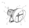
- the illumination device 10includes a housing 25 that encases various components of a light fixture.
- the housing 25includes an opening in which a set of light emitting diode (LED) modules 11 - 14 are secured to form a multi-module LED structure 18 .
- the LED modules 11 - 14are positioned to emit light away from the fixture.
- Each LED moduleincludes a frame that holds a set of LEDs arranged in an array or other configuration, and in various embodiments the set of LEDs may be of a number that is sufficient to provide a high intensity LED device.
- the openingalso provides a sensor compartment 15 in which one or more sensors may be installed to detect information about the environment exterior to the device.
- the sensors included in the sensor compartmentmay include sensors that are configured to ambient temperature, or properties of light such as color rendering index (CRI), D uv , color temperature (CCT), intensity or other properties of light in the ambient area in front of the LED modules 11 - 14 .
- the sensor compartment 15may be fully enclosed in a housing to protect the sensors from rain and dust, or at least some of the compartment may include an opening to ambient air.
- some or all of the sensorsmay be positioned in the LED modules instead of or in addition to the sensor compartment.
- the fixturemay include one or more reflectors 19 , such as mirrors or other reflective substrates, positioned and angled to reflect some of the light emitted by the LED modules toward the sensor compartment 15 .
- the reflectors 19are reflective structures that may be attached to the housing 25 , the shroud 29 (described below), any of the LED modules 11 - 14 , or any other suitable component of the fixtures. In this way, the sensor(s) may be positioned at or near the same plane as the LEDs, rather than substantially above the plane.
- the opening of the housing 25may be circular as shown, with the sensor housing 15 positioned at the center of the circle and the LED modules 11 - 14 positioned around the central open section to form a ring-shaped overall LED structure, although other shapes and configurations are possible.
- the LED modules 11 - 14may include four modules, each of which is positioned in a quadrant of the circle as shown. Alternatively, any other number of LED modules, such as one, two, three, five or more LED modules, may be positioned within the opening in any configuration.
- the device's housing 25includes a body portion 27 and an optional shroud portion 29 .
- the body portion 27serves as a heat sink that dissipates heat that is generated by the LED modules.
- the body/heat sink 27may be formed of aluminum and/or other metal, plastic or other material, and it may include any number of fins 22 a . . . 22 n on the exterior to increase its surface area that will contact a surrounding cooling medium (typically, air).
- the body portion 27may have a bowl shape (i.e., semi-hemispherical) as shown, the LED structure 18 may fit within the opening of the bowl, and heat from the LED modules 11 - 14 may be drawn away from the LED structure and dissipated via the fins 22 a . . . 22 n on the exterior of the bowl.
- the body 27may be formed as a single piece, or it may be formed of two pieces that fit together as in a clamshell-type structure as shown.
- a portion of the interior wall of the clamshell near its openingmay include a groove, ridge, or other supporting structure that is configured to receive and secure the LED structure in the opening when the clamshell is closed.
- the fins 22 a . . . 22 nmay be curved or arced as shown, with the base of each fin's curve/arc positioned proximate the opening/LED modules, and the apex of each fin's curve/arc positioned distal from the opening/LED modules to further help draw heat away from the LED modules.
- any openings of the housing 25will be sealed with a weatherproofing material such as rubber or silicone.
- the housingmay include a shroud 29 that extends from the body 27 and beyond the LED modules.
- the shroudmay be semi-circular in shape when the multi-module LED structure is circular, and it may be angled or shaped to shield an upper portion of the light assembly from rain while directing, focusing and/or reflecting light so that the light is concentrated in a desired direction (e.g., downward).
- the housing 25may provide a dust-resistant and water-resistant housing that protects electronic components of the illumination device. This may be sufficient to meet the standards required to provide a National Electrical Manufacturers Association (NEMA) type 1 or type 2 enclosure.
- NEMANational Electrical Manufacturers Association
- the housingmay sealed to provide a NEMA type 3 enclosure.
- the power supply 30may include a battery, solar panel, or circuitry to receive power from an external and/or other internal source.
- the external housing of the power supply 30also may include fins to help dissipate heat from the power supply.
- the fins of the power supplymay have a longest dimension that extends away from the LED structure (i.e., perpendicular to the widest dimension of the LED structure) to help with heat dissipation.
- Power wiringmay be positioned within the body 27 to convey energy from the power supply 30 to the LED array modules 11 - 14 .
- the power supply 30may extend from the rear of the housing as shown, or it may be placed into the housing so that it is flush or substantially flush with the rear of the housing 25 , or it may be configured to extend to some point between being flush with the housing 25 and the extended position of the configuration shown in FIG. 2 .
- the housingmay be attached to a support structure 40 , such as a base or mounting yoke, optionally by one or more connectors 41 .
- the connectors 41may include axles about which the housing and/or support structure may be rotated to enable the light assembly to be positioned to direct light at a desired angle.
- FIG. 3helps to illustrate components of the lighting device that can, in some embodiments, have self-cooling effects through its use of a sensor opening 15 in the front of the bowl (which is otherwise covered by the LED structure).
- a sensor opening 15in the front of the bowl (which is otherwise covered by the LED structure).
- heat generated by the LEDswill rise and dissipate through the heat sink, creating a negative pressure that may draw cool ambient air into the housing via an opening that is positioned proximate to (i.e., at, near or around) the sensor compartment 15 .
- This chimney effecthelps keep the LED modules and other components cool during operation.
- FIG. 3also illustrates that the shroud 29 may have a variable width so that an upper portion positioned at the top of the LED structure 18 is wider than a lower portion positioned at the bottom and/or along the sides of the LED structure. This helps to reduce the amount of light wasted to the atmosphere by reflecting and redirecting stray light downward to the intended illumination surface.
- the power supply 30may be detachable from the lighting device's housing 25 so that it can be replaced and/or removed for maintenance without the need to remove the entire device from an installed location, or so that it can be remotely mounted to reduce weight.
- the power supplymay include a power supply housing made of a set of fins 32 a . . . 32 n that are positioned lengthwise along an axis that extends away from the LED array when the power supply is installed in the device. The fins of the power supply housing thus provide an additional heat sink that draws heat away from the power supply during operation.
- the power supply housing and/or a portion of the lighting unit housing 25may include one or more antennae, transceivers or other communication devices 34 that can receive control signals from an external source.
- the illumination devicemay include a wireless receiver and an antenna that is configured to receive control signals via a wireless communication protocol.
- a portion of the lighting unit housing 25 or shroud 29may be equipped with an attached laser pointer that can be used to identify a distal point in an environment to which the lighting device directs its light. The laser pointer can thus help with installation and alignment of the device to a desired focal point.
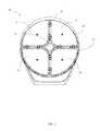
- FIG. 5illustrates a top view of the device 10 and shows one embodiment of how the heat sink may help to keep the LED structure cool.
- the housingmay be substantially or fully enclosed to provide a dome that receives the LED structure.
- the body portion 27 of the housingmay be open so that the fins 22 a . . . 22 n are positioned to extend away from the shroud 29 at an angle that is substantially perpendicular to the axis of the widest dimension (i.e., supporting panels) of the LED structure and shroud's opening.
- the fins 22 a . . . 22 nmay be positioned substantially vertically (i.e., lengthwise from a top portion of the LED array structure and shroud 29 to a bottom portion of the same).
- one or more lateral supports 23 a . . . 23 nmay be interconnected with the fins to provide support to the housing.
- the lateral supports 23 a . . . 23 nmay be positioned substantially parallel to the axis of the widest dimension of the LED structure as shown, or they may be curved to extend away from the LED structure, or they may be formed of any suitable shape and placed in any position.
- Each supportmay connect two or more of the fins. In this embodiment shown in FIG. 5 , the fins and optional supports 23 a .
- . . 23 nform the body portion 27 as a grate, and hot air may rise through the spaces that exist between the fins and supports of the grate.
- precipitationmay freely fall through the openings of the grate.
- any small debrissuch dust or bird droppings
- any small debristhat is caught in the grate may be washed away when precipitation next occurs.
- FIG. 4shows that a thermal insulating structure 37 may be positioned in the body and may receive the power supply so that the power supply is secured to the body but thermally separated from the body.
- the thermal insulating structure 37may be a structure that provides a barrier or wall, a plate, a ring that separates the fins of the body from those of the power supply, or any other suitable configuration.
- the thermal insulating structuremay be made of any suitable insulating material, such as a ceramic material.
- FIG. 5also shows that the insulating structure may have a central opening so that the power supply 30 may be received into the body 27 via a receptacle 35 .
- the receptacle 35may have inner dimensions that are at least as large as those of the power supply's housing.
- the receptacle and/or any portions of the body 27may removably secure the power supply 30 in place by friction and/or by or more connectors such as clips, hooks, bolts or other connecting structures.
- the body 27may have a number of anchors 52 a . . . 52 n that receive and secure one or more connectors of the power supply.
- the power supply 30may include one or more plugs, wires or other connectors so that the supply can deliver power to the LED structure. Note that the power supply 30 is optional and need not be part of the lighting device.
- the lighting devicecan be connected to an external power source by one or more wires, plugs, busses or other conductors.
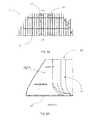
- FIG. 6Aalso illustrates a cross section A-A.
- FIG. 6Bshows a side view of this cross section in a top half 27 a of the body, with the uppermost portion of the body portion illustrated to the right in FIG. 6B , and the lower section of the body portion illustrated to the left in FIG. 6B .
- the fins of the cross-sectionsweep away from the LED structure 18 , and form a cavity 29 within the body to provide a heat sink.
- the rightmost portion 27 amay be connected to a lower body portion as illustrated in FIG. 7 .
- the fins and connecting structures of the body portion 27are made of a durable yet lightweight material, such as aluminum, an aluminum alloy such as A380 or ADC12, or other materials.
- FIG. 7illustrates that the housing 27 may be formed of two or more molded sections 27 a , 27 b that fit together as a clamshell-type structure.
- Each section 27 a , 27 bmay include one or more pins, receptacles, clips, or other receiving structures that help align and/or secure the sections together when positioned in place and connected to the shroud and/or power supply receptacle (shown in other Figures).
- the two sections 27 a , 27 bform a cavity 29 within the body when connected.
- FIG. 8illustrates that each housing section 27 a may form part of the opening in which the LED structure resides.
- Each LED module of the LED structuremay include one or more conducting substrates 38 that serve to hold the LEDs in place and provide the primary cooling path to the LEDs.
- the substratesmay be made of any support material (such as fiberglass or aluminum) with conductive elements (such as traces, bars or wires) placed thereon or therein to direct power to the LEDs.
- FIG. 8also illustrates an embodiment in which two LED modules form the LED structure, and each LED module is configured in a half-circle configuration. Thus, with a circular opening, the LED modules may be semi-circular in shape so that two, three, four or more of them together form a circle that fits within the opening.
- FIG. 9illustrates an embodiment of the device, with an expanded view of one of the LED array modules 12 of the LED structure 18 .
- the module 12includes a conductive substrate 38 on which a number of LEDs 39 are positioned.
- the LEDs 39may be arranged in one or more rows, matrices, or other arrangements with corresponding components supported in place and/or spaced apart by supports.
- the LEDsmay form matrices of n ⁇ n LEDs, such as 4 ⁇ 4 or 8 ⁇ 8 matrices.
- the LEDs in each module 12may be positioned in curved rows so that when all modules are positioned within the opening, the LED structure 18 comprises concentric rings of LEDs.
- the grouping of LEDs for the purpose of power supply and controlmay or may not conform to the arrangement of the LEDs in rings, clusters, matrices or other groupings.
- the substrate 38may include a portion that is a printed circuit board.
- Driver circuitry on the circuit boardmay deliver current to the LEDs, and the LED array modules may include multi-wire connectors with prongs and/or receptacles for connecting to external conductors and/or signal wires, or other LED array modules.
- a lens cover 41may be positioned over the substrate 38 to protect the substrate 38 and LEDs 39 from the ambient elements, as well as to focus and/or direct light emitted by the LEDs 39 .
- FIGS. 10A and 10Billustrate an underside of an embodiment of a lens cover 41 .
- the lens cover 41includes a set of lenses 45 a . . . 45 n , each of which is positioned to fit over an LED that has been placed on the substrate.
- the LEDs, and thus the lenses,may form an array.
- more than one LEDmay share a lens.
- the spacing of LEDs (and thus the lenses) with respect to each othermay vary based on the size of the LEDs.
- each dome 45 nmay be dome-shaped, with the apex of each dome being flat or concave to receive light from the corresponding LED, and the larger part of each dome being positioned on the outer side the cover to direct the light.
- the standoff and slope of each domemay vary depending on the desired beam angle that is to be achieved by the lighting device.
- a lighting systemmay be provided with domes of at least six different shapes to correspond to various beam limiting (collimating) standards.
- the LEDsmay be domeless and/or equipped with other lens structures.
- FIGS. 10A and 10Billustrate an optional area of the lens cover 41 on which no lenses appear. This may be the case of a portion of the lens cover 41 covers an area of the substrate that contains no LEDs, or in areas where no lenses are desired to be positioned over the LEDs.
- the substratemay include a printed circuit board that provides control functions. If so, then the lens cover 41 will not need to include lenses in that area, and it may instead simply be a solid cover over those portions of the substrate.
- one or more LEDsmay be equipped with no domes over the LEDs so that the beam is not limited, or one or more LEDs may be equipped with a channel 47 that serves as a collimator to focus the beam of light from its associated LED.
- LEDsare normally manufactured with a primary lens.
- the dome lenses 45 a . . . 45 nmay be added as secondary lens structures over the LEDs' primary lenses.
- LEDs with no primary lensmay be used, in which case the dome lenses 45 a . . . 45 n may serve as the only lens for one or more of the LEDs.
- dome lenses 45 a . . . 45 nmay be spaced apart from each other, adjacent to each other as shown in FIGS. 10A and 10B , configured so that their bases slightly overlap, or in any combination of such positioning options. In situations where the bases overlap, a small amount of overlap may be selected to help reduce glare from the LED assembly during operation.
- the amount of overlapmay be any suitable amount, such as approximately 2% of the base area of each dome, approximately 3% of the base area of each dome, approximately 5% of the base area of each dome, approximate 7% of the base area of each dome, approximately 10% of the base area of each dome, any range between the percentages listed above, or other percentages.
- FIG. 11illustrates an example of a portion of an LED module 134 .
- the LED moduleincludes any number of LEDs 164 .
- the LEDsmay be arranged in rows, matrices, or other arrangements with corresponding components supported in place and/or spaced apart to form modules of any number of LEDs.
- the LEDsmay be arranged and mounted on a circuit board 160 .
- Driver circuitry on the circuit board 160may deliver current to the LEDs, and the LED array modules may include multi-wire connectors with prongs and/or receptacles for connecting to external conductors and/or signal wires, or other LED modules.
- One or more circuit control cards 55may be positioned under, adjacent to or otherwise near the LED modules to provide power to the LEDs.
- the LEDs to which power is suppliedmay be selectively controlled by control circuitry such as that described below in this document.
- the control cardmay include a supporting substrate made of a material such as fiberglass, and a non-transitory computable-readable memory for storing programming instructions and/or monitored data and/or operational history data, one or more processors, a field programmable gate array (FPGA), application specific integrated circuit (ASIC) or other integrated circuit structures, and a received for receiving control signals from an external transmitter.
- the LED module 134 and control card 55may be placed within an opening of one end of the housing body.
- the circuitry of the control card 55 and or the LED module 134may operate to maintain a constant current draw across the LEDs and automatically adjust the intensity of the emitted light in response to feedback collected by the sensors.
- each LED module 134may be arranged so that groups of LEDs are electrically connected in series. Each group may be served by a programmable system on a chip (SoC) 174 which serves to receive a command from telemetry and send duty cycle information to multiple strings of LEDs.
- SoCsystem on a chip
- the systemmay include one or more power supplies, each of which applies a default direct current (DC) voltage (e.g., 36 volts or 48 volts) to an LED group, and each LED in any given group may have a constant voltage drop across it.
- Each string of LEDsmay comprise a set of LEDs connected in series, so that the string maintains the circuit if one bulb should fail.
- the systemmay include sensors that monitor current and/or voltage drop across each series, or across individual LEDs in a series. If the values monitored by these sensors change, it may indicate that one or more LEDs in a string has failed. For example, if string includes five bulbs connected in parallel, each of which is rated at 2 amps (A) each, an applied current of 10 A will be divided equally across each bulb. If one bulb fails, the hardware may maintain the circuit, and the voltage drop across the string may occur, thus changing the intensity of light output by the device.
- A2 amps
- the control cardmay generate a command to adjust the drive current across that string to compensate for the lost bulb.
- the control cardmay do this by any suitable means, such as by adjusting a variable resistor that is connected in the power delivery circuit, or by causing a variable transformer to reduce the voltage, or by implementing a command on a programmable system on a chip.
- the systemmay also selectively control the remaining LEDs using pulse width modulation, as will be described in more detail below.
- the sensorsmay include light intensity sensors, CRI sensors, CCT sensors, D uv sensors, and/or ambient air temperature sensors.
- the control cardmay be programmed to receive data from the sensors and selectably control the LEDs to maintain a desired light output when it determines that measured light intensity, CRI, CCT, D uv , or ambient air temperature exceeds or falls below a threshold.
- the thresholdmay be a value, or it may be a range of values with an upper and lower value.
- the thresholdmay be a time-sensitive threshold, such as a threshold amount of change within a certain period of time or a sustained measurement above or below a threshold over a certain period of time.
- the control cardcontrols the LEDs by pulse width modulation (PWM)
- PWMpulse width modulation
- an oscillating output from the processorrepeatedly turns the LEDs on and off by applying a pulsed voltage.
- Each pulseis of a constant voltage level, and the control circuitry varies the width of each pulse and/or the space between each pulse.
- the LEDsWhen a pulse is active, the LEDs may be turned on, and when the pulses are inactive the LEDs may be turned off. If the duty cycle of the “on” state is 50%, then the LEDs may be on during 50% of the overall cycle of the control pulses.
- the pulsesare delivered rapidly so that the human eye does not detect a strobing effect—at least 24 pulses per second.
- the control cardmay dim the lights by reducing the duty cycle—and effectively extending the time period between each “on” pulse-so that the LEDs are off more than they are on. Alternatively, the control card may increase the brightness of the LEDs by increasing the duty cycle.
- the control cardmay receive data from the sensors and apply that data to a rule set to determine whether to increase, decrease, or maintain the intensity of the LEDs. For example, if an ambient air temperature sensor detects that the temperature in the vicinity of the LED array module exceeds a threshold, the control card may cause the LEDs to dim by reducing the voltage output of each transformer and/or reducing the duty cycle of the LEDs in the module. If a light sensor detects that an ambient light level is above a desired range, the control circuitry may automatically reduce the brightness of a group of the LEDs by decreasing a width of voltage pulses applied to the group of LEDs or increasing spacing between voltage pulses applied to the group of LEDs to maintain the ambient light level within the desired range.
- control circuitrymay automatically reduce (or increase) increase the brightness a group of the LEDs by reducing (or increasing) a width of voltage pulses applied to the group of LEDs, or by increasing (or decreasing) spacing between voltage pulses applied to the group of LEDs to maintain the ambient light level within a desired range.
- any LED modulemay include several LED strings or groups of different colors.
- a modulemay include a red (R) LED series, a green (G) LED series, a blue (B) LED series, and a white (W) LED series. If so, the color of light emitted by the unit may be selectably controlled by the control card in response to external commands as described below.
- any LED modulemay include white LEDs of different color temperatures so that they can be selectively driven at different levels to produce variable temperature white light from the same fixture.
- any LED modulemay include various strings or groups, all of which emit white light, but which collectively exhibit a variety of color temperatures.
- various LED lampsmay have strings or other sets of LEDs that exhibit color temperatures ranging from about 2700K to about 6500K, from about 4000K to about 6500K, in a range around 5000K, or other CCT ranges and combinations.
- the control cardmay automatically alter the drive currents delivered to particular sets of LEDs in order to maintain a desired CCT output by the device.
- an illumination devicemay have a first set of LEDs having a CCT of 4000K and second set of LEDs having a CCT of 6500K.
- the light fixture control cardmay include programming to maintain the light emitted by the device at a threshold level or threshold range.
- the control cardmay implement a process that applies an algorithm, reference a lookup table, or use other suitable methods to determine what drive currents to apply to each of the groups of LEDs to achieve the desired CCT. For example, if the desired output is a CCT of 5000K, the system may drive the 4000K LEDs at a current of 1250 ma and the 6500K LEDs at a drive current of about 900 ma.
- the same process or a similar processmay be applied when the sensor measures D uv .
- the algorithms and lookup table amountsmay be set so that the system does not substantially change the illuminance level measured by light intensity sensors in the sensor compartment when the drive current changes are implemented.
- the programming on the control cardmay be programmed in any suitable format, such as in a field programmable gate array (FPGA), or as computer-readable instructions stored in a computer-readable memory device and configured to be read and implemented by a processor of the control card.
- FPGAfield programmable gate array
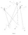
- FIG. 12illustrates that any number of lighting devices 10 a , 10 b , 10 c such as those disclosed in this document may be positioned in an environment, such as a wall, ceiling, mast, tower or other supporting structure in a stadium, arena, concert hall, outdoor amphitheater or other location.
- Each illumination devicemay include or be connected to a device controller 210 ( a ), 210 ( b ), 210 ( c ) that includes wiring and circuitry to supply power and/or control signals to one or more lights.
- a device controllermay be an external device, or an integral device that includes various components of an illumination device's control card.
- Each device controller 210 ( a ), 210 ( b ), 210 ( c )may include a receiver that receives wireless signals from one or more transmitters. The transmitters may be included in, for example, one or more user interface devices 202 .
- Each interface device 202may include selectable user inputs, programming, a processor or circuitry, and a transmitter for transmitting command signals to the various illumination devices.
- the user inputsmay include inputs to turn certain lights in a certain zone of an environment on or off, in which case the interface device will generate and send signals with encoded data that instruct the zone's lights to turn on and off.
- the user inputsalso may include brightness level adjustments for one or more zones and/or lights, or scenes that are designed to set various lighting devices at various brightness levels.
- Each user input commandwill cause the user interface device to send a signal that includes data indicating which illumination devices should be operated by the signal.
- a control devicedetects a signal that is intended for its illumination device, it will cause its illumination device to execute the command that corresponds to the control signal. The system may do this by adjusting the light intensity using PWM, as described elsewhere in this document.
- any number of external light sensors 205 a - 205 nmay be positioned at a location or multiple locations in an environment, such as a stadium playing field, a stage in a concert hall, or a court/floor/ice rink in an area, to detect the intensity of light.
- the external light sensorsmay include transmitters that send status information and/or commands to any or all of the illumination device controllers and/or the interface device.
- a particular illumination device controller 210 cmay be programmed to detect signals from a particular sensor 205 a that is positioned in an area at which the controller's corresponding light fixture 10 c directs light. The sensor may sense light intensity in its vicinity and transmit intensity data to the device controller 210 c .
- the device controller 210 cmay be programmed to increase the LED device's 10 c brightness if the local intensity data is less than a threshold, or it may decrease the LED device's 10 c brightness if the local intensity data is greater than a threshold. As described above, the controller may do this by increasing or decreasing the frequency of “on” signals that cycle the LEDs on and off by PWM.
- the sensor 205 aitself may include programming and electronics that cause it to send a command to the controller 210 c , such as an increase brightness command if local intensity is less than a threshold level or a decrease brightness command if local intensity is greater than a threshold level.
- LED modules and control systems and methodsare not limited to the embodiment of the illumination devices disclosed in this document.
- the LED modules, control systems and control methodsmay be applied to other LED illumination structures, such as those disclosed in International Patent Application No. PCT/US2012/069442, filed Sep. 13, 2012 by Nolan et al., the disclosure of which is incorporated herein by reference in its entirety.
Landscapes
- Engineering & Computer Science (AREA)
- General Engineering & Computer Science (AREA)
- Power Engineering (AREA)
- Arrangement Of Elements, Cooling, Sealing, Or The Like Of Lighting Devices (AREA)
- Circuit Arrangement For Electric Light Sources In General (AREA)
- Non-Portable Lighting Devices Or Systems Thereof (AREA)
- Microelectronics & Electronic Packaging (AREA)
Abstract
Description
Claims (47)
Priority Applications (3)
| Application Number | Priority Date | Filing Date | Title |
|---|---|---|---|
| US14/573,619US9188307B2 (en) | 2013-12-17 | 2014-12-17 | High intensity LED illumination device with automated sensor-based control |
| US14/942,501US9408271B2 (en) | 2013-12-17 | 2015-11-16 | High intensity LED illumination device with automated sensor-based control |
| US15/221,159US10136501B2 (en) | 2013-12-17 | 2016-07-27 | High intensity LED illumination device with automated sensor-based control |
Applications Claiming Priority (2)
| Application Number | Priority Date | Filing Date | Title |
|---|---|---|---|
| US201361917030P | 2013-12-17 | 2013-12-17 | |
| US14/573,619US9188307B2 (en) | 2013-12-17 | 2014-12-17 | High intensity LED illumination device with automated sensor-based control |
Related Child Applications (1)
| Application Number | Title | Priority Date | Filing Date |
|---|---|---|---|
| US14/942,501ContinuationUS9408271B2 (en) | 2013-12-17 | 2015-11-16 | High intensity LED illumination device with automated sensor-based control |
Publications (2)
| Publication Number | Publication Date |
|---|---|
| US20150173148A1 US20150173148A1 (en) | 2015-06-18 |
| US9188307B2true US9188307B2 (en) | 2015-11-17 |
Family
ID=53367923
Family Applications (5)
| Application Number | Title | Priority Date | Filing Date |
|---|---|---|---|
| US14/573,619ActiveUS9188307B2 (en) | 2013-12-17 | 2014-12-17 | High intensity LED illumination device with automated sensor-based control |
| US14/573,668Active2035-10-21US10182485B2 (en) | 2013-12-17 | 2014-12-17 | Lens structure for high intensity LED fixture |
| US14/573,584ActiveUS9888545B2 (en) | 2013-12-17 | 2014-12-17 | High intensity LED illumination device |
| US14/942,501ActiveUS9408271B2 (en) | 2013-12-17 | 2015-11-16 | High intensity LED illumination device with automated sensor-based control |
| US15/221,159Active2035-01-15US10136501B2 (en) | 2013-12-17 | 2016-07-27 | High intensity LED illumination device with automated sensor-based control |
Family Applications After (4)
| Application Number | Title | Priority Date | Filing Date |
|---|---|---|---|
| US14/573,668Active2035-10-21US10182485B2 (en) | 2013-12-17 | 2014-12-17 | Lens structure for high intensity LED fixture |
| US14/573,584ActiveUS9888545B2 (en) | 2013-12-17 | 2014-12-17 | High intensity LED illumination device |
| US14/942,501ActiveUS9408271B2 (en) | 2013-12-17 | 2015-11-16 | High intensity LED illumination device with automated sensor-based control |
| US15/221,159Active2035-01-15US10136501B2 (en) | 2013-12-17 | 2016-07-27 | High intensity LED illumination device with automated sensor-based control |
Country Status (2)
| Country | Link |
|---|---|
| US (5) | US9188307B2 (en) |
| CA (3) | CA2875019C (en) |
Cited By (10)
| Publication number | Priority date | Publication date | Assignee | Title |
|---|---|---|---|---|
| US9800431B2 (en) | 2016-03-08 | 2017-10-24 | Ephesus Lighting, Inc. | Controllers for interconnected lighting devices |
| US9900951B1 (en)* | 2017-07-13 | 2018-02-20 | Elements Performance Materials Limited | Lamp having the thermal sensing elements disposed at optimal positions and thermal controlling method thereof |
| US10085317B2 (en) | 2016-03-08 | 2018-09-25 | Cooper Lighting, Llc | Control system for lighting devices |
| US10098201B1 (en) | 2017-10-17 | 2018-10-09 | Cooper Lighting, Llc | Method and system for controlling functionality of lighting devices from a portable electronic device |
| US10143053B1 (en) | 2017-10-17 | 2018-11-27 | Cooper Lighting, Llc | Method and system for controlling functionality of lighting devices |
| US10334676B2 (en) | 2017-05-17 | 2019-06-25 | Eaton Intelligent Power Limited | LED luminaire with constant current per-module control |
| WO2020234183A1 (en) | 2019-05-17 | 2020-11-26 | Signify Holding B.V. | Shared power topology for led luminaires |
| WO2021063884A1 (en) | 2019-10-01 | 2021-04-08 | Signify Holding B.V. | Led luminaire multiplexing with constant current driver |
| US10982834B2 (en)* | 2017-11-17 | 2021-04-20 | Smart Light Source Co., LLC | Thermal control of locomotive headlight |
| US20220170617A1 (en)* | 2020-11-30 | 2022-06-02 | Hgci, Inc. | Onboard conroller for light fixture for indoor grow application |
Families Citing this family (39)
| Publication number | Priority date | Publication date | Assignee | Title |
|---|---|---|---|---|
| US9189996B2 (en)* | 2013-12-17 | 2015-11-17 | Ephesus Lighting, Inc. | Selectable, zone-based control for high intensity LED illumination system |
| CA2875019C (en) | 2013-12-17 | 2021-04-06 | Ephesus Lighting, Inc. | High intensity led illumination device |
| CN107636390A (en)* | 2015-03-20 | 2018-01-26 | 沙特基础工业全球技术公司 | Plastic heat sinks for lighting equipment |
| FR3036687B1 (en)* | 2015-05-28 | 2019-01-25 | Zodiac Aero Electric | LIGHTING DEVICE FOR AN AIRCRAFT FOR THE INTEGRATION OF ADDITIONAL FUNCTIONS IN ITS CENTER |
| US10161577B2 (en)* | 2015-12-28 | 2018-12-25 | Eaton Intelligent Power Limited | Electrical connection of control circuit card to power supply in LED luminaire assembly |
| WO2017117237A1 (en) | 2015-12-28 | 2017-07-06 | Ephesus Lighting, Inc. | Method and system for alignment of illumination device |
| US10371345B2 (en) | 2015-12-28 | 2019-08-06 | Eaton Intelligent Power Limited | Light emitting diode (LED) module for LED luminaire |
| US9730302B2 (en) | 2015-12-28 | 2017-08-08 | Ephesus Lighting, Inc. | System and method for control of an illumination device |
| USD800376S1 (en) | 2015-12-28 | 2017-10-17 | Ephesus Lighting, Inc. | Light emitting diode (LED) module for a lighting device |
| WO2017152739A1 (en)* | 2016-03-07 | 2017-09-14 | 欧普照明股份有限公司 | Optical element, light source module and illumination device |
| USD802197S1 (en)* | 2016-04-22 | 2017-11-07 | Lighting Solutions Group Llc | Lamp |
| CN107588349B (en)* | 2016-07-08 | 2021-06-15 | 卡任特照明解决方案有限公司 | Lamp set |
| USD831261S1 (en) | 2016-07-26 | 2018-10-16 | Lighting Solutions Group Llc | Lamp |
| CN206145452U (en)* | 2016-09-20 | 2017-05-03 | 欧普照明股份有限公司 | Outdoor lamp |
| FR3062460B1 (en)* | 2017-02-01 | 2020-11-13 | Valeo Vision | LIGHT MODULE FOR VEHICLE HEADLIGHT |
| USD820509S1 (en) | 2017-02-13 | 2018-06-12 | Lighting Solutions Group Llc | Light fixture |
| US20180249758A1 (en)* | 2017-03-05 | 2018-09-06 | SMB Labs, LLC | Dynamically Responsive Smoking Apparatus and Method of Affixing Electronics Thereon |
| CN108107055B (en)* | 2017-11-20 | 2019-11-15 | 珠海格力电器股份有限公司 | Control method and device of intelligent power module, storage medium and processor |
| US10837630B2 (en) | 2018-03-02 | 2020-11-17 | Signify Holding B.V. | Lighting device alignment calibration system |
| USD955027S1 (en) | 2018-09-12 | 2022-06-14 | Lighting Solutions Group Llc | Light |
| USD921256S1 (en)* | 2018-11-28 | 2021-06-01 | Shenzhen Huadian Lighting Co., Ltd. | LED stadium light |
| US11076460B2 (en)* | 2019-01-18 | 2021-07-27 | Alliance Sports Group, L.P. | Lighting system |
| US10697626B1 (en) | 2019-01-18 | 2020-06-30 | Signify Holding B.V. | LED luminaire heatsink assembly |
| US11543110B2 (en)* | 2019-01-18 | 2023-01-03 | Alliance Sports Group, L.P. | Lighting system |
| USD912872S1 (en) | 2019-01-21 | 2021-03-09 | Lighting Solutions Group Llc | Light |
| JP2020194672A (en)* | 2019-05-27 | 2020-12-03 | 三菱電機株式会社 | Luminaire |
| CN110366301A (en)* | 2019-06-12 | 2019-10-22 | 张会 | A semiconductor laser lighting device with heat dissipation function |
| USD1060803S1 (en)* | 2019-07-31 | 2025-02-04 | Sportsbeams Lighting, Inc. | Sports venue light |
| CN210637839U (en)* | 2019-08-26 | 2020-05-29 | 厦门赢科光电有限公司 | a bulb light |
| US11013079B2 (en)* | 2019-09-06 | 2021-05-18 | Robe Lighting S.R.O. | Removable LED module |
| US10801708B1 (en)* | 2019-11-25 | 2020-10-13 | Signify Holding B.V. | Quick mounting yoke for an LED lighting device |
| US11015796B1 (en)* | 2019-11-26 | 2021-05-25 | M3 Innovation, LLC | Thermally dissipative unibody lighting structure |
| USD956302S1 (en)* | 2020-06-19 | 2022-06-28 | Shenzhen Snc Opto Electronic Co., Ltd. | LED lamp |
| USD1005554S1 (en) | 2021-08-16 | 2023-11-21 | Lighting Solutions Group Llc | Grow light |
| CN114992552A (en)* | 2022-06-16 | 2022-09-02 | 惠州瀚星光电科技有限公司 | Light source module and lighting lamp |
| KR102673449B1 (en)* | 2022-07-29 | 2024-06-10 | 주식회사 케이비글로벌 | Dual-adjustable automatic dimming lighting |
| USD1044077S1 (en)* | 2022-11-10 | 2024-09-24 | Shenzhen Snc Opto Electronic Co., Ltd | LED lamp |
| WO2024179961A1 (en)* | 2023-03-02 | 2024-09-06 | Signify Holding B.V. | Led lighting arrangement |
| USD1054082S1 (en)* | 2023-06-08 | 2024-12-10 | Dong Guan Pan American Electronics C0., Ltd | Court lamp |
Citations (18)
| Publication number | Priority date | Publication date | Assignee | Title |
|---|---|---|---|---|
| US6962423B2 (en) | 2001-11-06 | 2005-11-08 | Honeywell International Inc. | Multi-mode searchlight |
| US20090040470A1 (en) | 2007-08-08 | 2009-02-12 | Masayuki Fukui | Projecting apparatus |
| US20090067172A1 (en) | 2007-09-05 | 2009-03-12 | Masaru Inoue | Lighting apparatus |
| US20100225241A1 (en)* | 2009-01-28 | 2010-09-09 | Minoru Maehara | Illumination device and method for controlling a color temperature of irradiated light |
| US20100277076A1 (en)* | 2006-11-15 | 2010-11-04 | Ecolivegreen Corp. | System for adjusting a light source by sensing ambient illumination |
| US20110062872A1 (en)* | 2009-09-11 | 2011-03-17 | Xuecheng Jin | Adaptive Switch Mode LED Driver |
| US20110095690A1 (en) | 2009-10-22 | 2011-04-28 | Thermal Solution Resources, Llc | Overmolded LED Light Assembly and Method of Manufacture |
| US20120033419A1 (en) | 2010-08-06 | 2012-02-09 | Posco Led Company Ltd. | Optical semiconductor lighting apparatus |
| US20120153837A1 (en)* | 2010-12-16 | 2012-06-21 | Electronics And Telecommunications Research Institute | Method and apparatus for correcting light |
| US8227960B2 (en) | 2010-03-11 | 2012-07-24 | Tsung-Hsien Huang | LED projector lamp with improved structure of radiation fins |
| US20120235579A1 (en)* | 2008-04-14 | 2012-09-20 | Digital Lumens, Incorporated | Methods, apparatus and systems for providing occupancy-based variable lighting |
| US20120261105A1 (en) | 2011-04-12 | 2012-10-18 | Asia Vital Components Co., Ltd. | Led heat sink and manufacturing method thereof |
| US8371717B2 (en) | 2010-07-20 | 2013-02-12 | Foxsemicon Integrated Technology, Inc. | LED light emitting device having temperature sensor for controlling current supplied to LEDs therof |
| WO2013090536A1 (en) | 2011-12-13 | 2013-06-20 | Ephesus Technologies, Llc | High intensity light-emitting diode luminaire assembly |
| US20130200796A1 (en)* | 2012-02-02 | 2013-08-08 | Posco Led Company Ltd. | Heat sink and led illuminating apparatus comprising the same |
| US8573801B2 (en) | 2010-08-30 | 2013-11-05 | Alcon Research, Ltd. | LED illuminator |
| US20140159583A1 (en) | 2008-11-18 | 2014-06-12 | Ringdale, Inc. | Method and led apparatus for lighting with led lighting controller |
| US8841859B2 (en) | 2008-04-14 | 2014-09-23 | Digital Lumens Incorporated | LED lighting methods, apparatus, and systems including rules-based sensor data logging |
Family Cites Families (35)
| Publication number | Priority date | Publication date | Assignee | Title |
|---|---|---|---|---|
| US2254962A (en)* | 1937-09-22 | 1941-09-02 | George M Cressaty | Unitary lens system |
| JP3195294B2 (en)* | 1998-08-27 | 2001-08-06 | スタンレー電気株式会社 | Vehicle lighting |
| EP1048085B1 (en) | 1998-10-21 | 2007-11-14 | Koninklijke Philips Electronics N.V. | Led module and luminaire |
| US7202613B2 (en) | 2001-05-30 | 2007-04-10 | Color Kinetics Incorporated | Controlled lighting methods and apparatus |
| US6547423B2 (en) | 2000-12-22 | 2003-04-15 | Koninklijke Phillips Electronics N.V. | LED collimation optics with improved performance and reduced size |
| US6724543B1 (en)* | 2002-10-23 | 2004-04-20 | Visteon Global Technologies, Inc. | Light collection assembly having mixed conic shapes for use with various light emitting sources |
| USD495821S1 (en) | 2003-04-28 | 2004-09-07 | Grand General Accessories Manufacturing Inc. | Elliptical reflector for multi-LED vehicle lights |
| WO2005043637A1 (en)* | 2003-10-31 | 2005-05-12 | Toyoda Gosei Co., Ltd. | Light emitting device |
| US20050179041A1 (en) | 2004-02-18 | 2005-08-18 | Lumileds Lighting U.S., Llc | Illumination system with LEDs |
| JP2009545894A (en) | 2006-07-31 | 2009-12-24 | スリーエム イノベイティブ プロパティズ カンパニー | LED source with hollow condenser lens |
| JP4557037B2 (en)* | 2008-04-08 | 2010-10-06 | ウシオ電機株式会社 | LED light emitting device |
| USD636926S1 (en) | 2010-03-25 | 2011-04-26 | Dongmyung Lighting Co., Ltd. | Reflector for illuminator |
| USD648886S1 (en) | 2010-04-10 | 2011-11-15 | Lg Innotek Co., Ltd. | Head of a street lamp |
| JP5441801B2 (en)* | 2010-04-12 | 2014-03-12 | 株式会社小糸製作所 | Vehicle lighting |
| JP4865051B2 (en) | 2010-04-20 | 2012-02-01 | シャープ株式会社 | PAR type lighting device |
| JP4842387B1 (en)* | 2010-06-11 | 2011-12-21 | シャープ株式会社 | Lighting device |
| US9523491B2 (en) | 2010-10-07 | 2016-12-20 | Hubbell Incorporated | LED luminaire having lateral cooling fins and adaptive LED assembly |
| WO2012055046A1 (en)* | 2010-10-27 | 2012-05-03 | Dbm Reflex Enterprises Inc. | Lens array assembly for solid state light sources and method |
| US8272759B2 (en)* | 2011-01-18 | 2012-09-25 | Dbm Reflex Of Taiwan Co., Ltd. | Light-emitting diode lampshade |
| GB2513221B (en) | 2011-03-31 | 2015-07-29 | Litonics Ltd | Lighting device |
| US20140028200A1 (en) | 2011-05-12 | 2014-01-30 | LSI Saco Technologies, Inc. | Lighting and integrated fixture control |
| JP6022197B2 (en) | 2011-06-29 | 2016-11-09 | ローム株式会社 | LED lighting fixtures |
| USD679446S1 (en) | 2011-11-17 | 2013-04-02 | Myotek Pacific Corp. | LED spot lamp |
| US9392651B2 (en) | 2012-04-11 | 2016-07-12 | Koninklijke Philips N.V. | Lighting methods and apparatus with selectively applied face lighting component |
| JP6081795B2 (en) | 2012-12-27 | 2017-02-15 | 東芝ライテック株式会社 | Lighting control system and lighting |
| TW201430275A (en)* | 2013-01-24 | 2014-08-01 | Ming-Yuan Wu | Modular LED lamp structure |
| US9210760B2 (en) | 2013-08-26 | 2015-12-08 | Abl Ip Holding Llc | Enhancements for LED lamps for use in luminaires |
| EP3045019B1 (en) | 2013-09-13 | 2019-04-10 | Cooper Technologies Company | System and method for auto-commissioning based on smart sensors |
| USD714991S1 (en) | 2013-11-06 | 2014-10-07 | Grote Industries, Inc. | Lamp |
| CA2875019C (en) | 2013-12-17 | 2021-04-06 | Ephesus Lighting, Inc. | High intensity led illumination device |
| US9189996B2 (en) | 2013-12-17 | 2015-11-17 | Ephesus Lighting, Inc. | Selectable, zone-based control for high intensity LED illumination system |
| USD757992S1 (en) | 2014-08-28 | 2016-05-31 | Chen-Wei Hsu | Illumination lense |
| US9307621B1 (en) | 2014-12-08 | 2016-04-05 | Cisco Technology, Inc. | Networked lighting management |
| USD775407S1 (en) | 2015-02-27 | 2016-12-27 | Star Headlight & Lantern Co., Inc. | Optical lens for projecting light from LED light emitters |
| USD774688S1 (en) | 2015-07-17 | 2016-12-20 | Lightforce Australia Pty Ltd. | LED reflector array |
- 2014
- 2014-12-17CACA2875019Apatent/CA2875019C/enactiveActive
- 2014-12-17USUS14/573,619patent/US9188307B2/enactiveActive
- 2014-12-17USUS14/573,668patent/US10182485B2/enactiveActive
- 2014-12-17CACA2875014Apatent/CA2875014A1/ennot_activeAbandoned
- 2014-12-17CACA3078222Apatent/CA3078222C/enactiveActive
- 2014-12-17USUS14/573,584patent/US9888545B2/enactiveActive
- 2015
- 2015-11-16USUS14/942,501patent/US9408271B2/enactiveActive
- 2016
- 2016-07-27USUS15/221,159patent/US10136501B2/enactiveActive
Patent Citations (19)
| Publication number | Priority date | Publication date | Assignee | Title |
|---|---|---|---|---|
| US6962423B2 (en) | 2001-11-06 | 2005-11-08 | Honeywell International Inc. | Multi-mode searchlight |
| US20100277076A1 (en)* | 2006-11-15 | 2010-11-04 | Ecolivegreen Corp. | System for adjusting a light source by sensing ambient illumination |
| US20090040470A1 (en) | 2007-08-08 | 2009-02-12 | Masayuki Fukui | Projecting apparatus |
| US20090067172A1 (en) | 2007-09-05 | 2009-03-12 | Masaru Inoue | Lighting apparatus |
| US8841859B2 (en) | 2008-04-14 | 2014-09-23 | Digital Lumens Incorporated | LED lighting methods, apparatus, and systems including rules-based sensor data logging |
| US20120235579A1 (en)* | 2008-04-14 | 2012-09-20 | Digital Lumens, Incorporated | Methods, apparatus and systems for providing occupancy-based variable lighting |
| US20140159583A1 (en) | 2008-11-18 | 2014-06-12 | Ringdale, Inc. | Method and led apparatus for lighting with led lighting controller |
| US20100225241A1 (en)* | 2009-01-28 | 2010-09-09 | Minoru Maehara | Illumination device and method for controlling a color temperature of irradiated light |
| US20110062872A1 (en)* | 2009-09-11 | 2011-03-17 | Xuecheng Jin | Adaptive Switch Mode LED Driver |
| US20110095690A1 (en) | 2009-10-22 | 2011-04-28 | Thermal Solution Resources, Llc | Overmolded LED Light Assembly and Method of Manufacture |
| US8227960B2 (en) | 2010-03-11 | 2012-07-24 | Tsung-Hsien Huang | LED projector lamp with improved structure of radiation fins |
| US8371717B2 (en) | 2010-07-20 | 2013-02-12 | Foxsemicon Integrated Technology, Inc. | LED light emitting device having temperature sensor for controlling current supplied to LEDs therof |
| US20120033419A1 (en) | 2010-08-06 | 2012-02-09 | Posco Led Company Ltd. | Optical semiconductor lighting apparatus |
| US8573801B2 (en) | 2010-08-30 | 2013-11-05 | Alcon Research, Ltd. | LED illuminator |
| US20120153837A1 (en)* | 2010-12-16 | 2012-06-21 | Electronics And Telecommunications Research Institute | Method and apparatus for correcting light |
| US20120261105A1 (en) | 2011-04-12 | 2012-10-18 | Asia Vital Components Co., Ltd. | Led heat sink and manufacturing method thereof |
| WO2013090536A1 (en) | 2011-12-13 | 2013-06-20 | Ephesus Technologies, Llc | High intensity light-emitting diode luminaire assembly |
| US20130200796A1 (en)* | 2012-02-02 | 2013-08-08 | Posco Led Company Ltd. | Heat sink and led illuminating apparatus comprising the same |
| US8760058B2 (en) | 2012-02-02 | 2014-06-24 | Posco Led Company Ltd. | Heat sink and LED illuminating apparatus comprising the same |
Non-Patent Citations (1)
| Title |
|---|
| International Search Report dated Apr. 29, 2013 for PCT/US2012/069442, international filed Dec. 13, 2012. |
Cited By (20)
| Publication number | Priority date | Publication date | Assignee | Title |
|---|---|---|---|---|
| US10085317B2 (en) | 2016-03-08 | 2018-09-25 | Cooper Lighting, Llc | Control system for lighting devices |
| US10779368B2 (en) | 2016-03-08 | 2020-09-15 | Signify Holding B.V. | Control system for lighting devices |
| US9800431B2 (en) | 2016-03-08 | 2017-10-24 | Ephesus Lighting, Inc. | Controllers for interconnected lighting devices |
| US10631377B2 (en) | 2016-03-08 | 2020-04-21 | Eaton Intelligent Power Limited | Control system for lighting devices |
| US10334676B2 (en) | 2017-05-17 | 2019-06-25 | Eaton Intelligent Power Limited | LED luminaire with constant current per-module control |
| US10701771B2 (en) | 2017-05-17 | 2020-06-30 | Signify Holding B.V. | LED luminaire with constant current per-module control |
| US9900951B1 (en)* | 2017-07-13 | 2018-02-20 | Elements Performance Materials Limited | Lamp having the thermal sensing elements disposed at optimal positions and thermal controlling method thereof |
| US10143053B1 (en) | 2017-10-17 | 2018-11-27 | Cooper Lighting, Llc | Method and system for controlling functionality of lighting devices |
| US10492266B2 (en) | 2017-10-17 | 2019-11-26 | Eaton Intellectual Power Limited | Method and system for controlling functionality of lighting devices from a portable electronic device |
| US10517153B2 (en) | 2017-10-17 | 2019-12-24 | Eaton Intelligent Power Limited | Method and system for controlling functionality of lighting devices |
| WO2019079049A1 (en) | 2017-10-17 | 2019-04-25 | Cooper Lighting, Llc | Method and system for controlling functionality of lighting devices from a portable electronic device |
| US10117303B1 (en) | 2017-10-17 | 2018-10-30 | Cooper Lighting, Llc | Method and system for controlling functionality of lighting devices from a portable electronic device |
| US10098201B1 (en) | 2017-10-17 | 2018-10-09 | Cooper Lighting, Llc | Method and system for controlling functionality of lighting devices from a portable electronic device |
| US10806007B2 (en) | 2017-10-17 | 2020-10-13 | Signify Holding B.V. | Method and system for controlling functionality of lighting devices from a portable electronic device |
| US10904966B2 (en) | 2017-10-17 | 2021-01-26 | Signify Holding B.V. | Method and system for controlling functionality of lighting devices |
| US10982834B2 (en)* | 2017-11-17 | 2021-04-20 | Smart Light Source Co., LLC | Thermal control of locomotive headlight |
| WO2020234183A1 (en) | 2019-05-17 | 2020-11-26 | Signify Holding B.V. | Shared power topology for led luminaires |
| WO2021063884A1 (en) | 2019-10-01 | 2021-04-08 | Signify Holding B.V. | Led luminaire multiplexing with constant current driver |
| US20220170617A1 (en)* | 2020-11-30 | 2022-06-02 | Hgci, Inc. | Onboard conroller for light fixture for indoor grow application |
| US11549672B2 (en)* | 2020-11-30 | 2023-01-10 | Hgci, Inc. | Onboard controller for light fixture for indoor grow application |
Also Published As
| Publication number | Publication date |
|---|---|
| US10136501B2 (en) | 2018-11-20 |
| US20150167937A1 (en) | 2015-06-18 |
| CA2875014A1 (en) | 2015-06-17 |
| CA3078222A1 (en) | 2015-06-17 |
| US20160338156A1 (en) | 2016-11-17 |
| US20150173148A1 (en) | 2015-06-18 |
| CA2875019A1 (en) | 2015-06-17 |
| US9408271B2 (en) | 2016-08-02 |
| US10182485B2 (en) | 2019-01-15 |
| US9888545B2 (en) | 2018-02-06 |
| CA2875019C (en) | 2021-04-06 |
| CA3078222C (en) | 2022-07-12 |
| US20160073464A1 (en) | 2016-03-10 |
| US20150167922A1 (en) | 2015-06-18 |
Similar Documents
| Publication | Publication Date | Title |
|---|---|---|
| US10136501B2 (en) | High intensity LED illumination device with automated sensor-based control | |
| US10051709B2 (en) | Selectable control for high intensity LED illumination system to maintain constant color temperature on a lit surface | |
| US8970131B2 (en) | Solid state lighting apparatuses and related methods | |
| US9414454B2 (en) | Solid state lighting apparatuses and related methods | |
| US8896235B1 (en) | High temperature LED system using an AC power source | |
| US20110019433A1 (en) | Led lighting device | |
| US20150257211A1 (en) | Solid state lighting apparatuses and related methods | |
| US20140228914A1 (en) | Solid state light emitting devices including adjustable melatonin suppression effects | |
| US20140293603A1 (en) | Led light bulb replacement with adjustable light distribution | |
| US20140022780A1 (en) | Led-based lighting unit with a high flux density led array | |
| US10948173B2 (en) | Luminaire, housing component for a luminaire and method for producing a luminaire | |
| US20120127722A1 (en) | Lamp And Use Of A Lamp | |
| US9593839B2 (en) | LED lamp for public lighting | |
| EP3119168B1 (en) | Aircraft led light unit | |
| JP3162698U (en) | Ornamental lighting fixture and aquarium fish tank using the same | |
| US10887963B2 (en) | Multi-mode power supply for an LED illumination device | |
| CA2875013C (en) | Selectable control for high intensity led illumination system to maintain constant color temperature | |
| KR101241348B1 (en) | Flourescent lamp led lighting apparatus and lighting system having the same | |
| KR20140002728U (en) | Led lighting fixtures for broadcasting or performance |
Legal Events
| Date | Code | Title | Description |
|---|---|---|---|
| AS | Assignment | Owner name:EPHESUS LIGHTING, INC., NEW YORK Free format text:ASSIGNMENT OF ASSIGNORS INTEREST;ASSIGNORS:CASPER, JOSEPH R.;NOLAN, CHRISTOPHER D.;WITKOWSKI, JOSEPH J.;AND OTHERS;REEL/FRAME:034531/0144 Effective date:20141216 | |
| STCF | Information on status: patent grant | Free format text:PATENTED CASE | |
| FEPP | Fee payment procedure | Free format text:PAT HOLDER NO LONGER CLAIMS SMALL ENTITY STATUS, ENTITY STATUS SET TO UNDISCOUNTED (ORIGINAL EVENT CODE: STOL); ENTITY STATUS OF PATENT OWNER: LARGE ENTITY | |
| AS | Assignment | Owner name:COOPER LIGHTING, LLC, OHIO Free format text:CERTIFICATE OF MERGER OF DOMESTIC CORPORATION INTO DOMESTIC LIMITED LIABILITY COMPANY;ASSIGNOR:EPHESUS LIGHTING, INC.;REEL/FRAME:046264/0351 Effective date:20161220 | |
| AS | Assignment | Owner name:EATON INTELLIGENT POWER LIMITED, IRELAND Free format text:ASSIGNMENT OF ASSIGNORS INTEREST;ASSIGNOR:COOPER LIGHTING, LLC;REEL/FRAME:046847/0462 Effective date:20171231 | |
| AS | Assignment | Owner name:COOPER LIGHTING, LLC, OHIO Free format text:MERGER;ASSIGNOR:EPHESUS LIGHTING, INC.;REEL/FRAME:047576/0649 Effective date:20161220 Owner name:EATON INTELLIGENT POWER LIMITED, IRELAND Free format text:ASSIGNMENT OF ASSIGNORS INTEREST;ASSIGNOR:COOPER LIGHTING, LLC;REEL/FRAME:047576/0654 Effective date:20171231 | |
| MAFP | Maintenance fee payment | Free format text:PAYMENT OF MAINTENANCE FEE, 4TH YEAR, LARGE ENTITY (ORIGINAL EVENT CODE: M1551); ENTITY STATUS OF PATENT OWNER: LARGE ENTITY Year of fee payment:4 | |
| AS | Assignment | Owner name:SIGNIFY HOLDING B.V., NETHERLANDS Free format text:ASSIGNMENT OF ASSIGNORS INTEREST;ASSIGNOR:EATON INTELLIGENT POWER LIMITED;REEL/FRAME:052681/0475 Effective date:20200302 | |
| AS | Assignment | Owner name:SIGNIFY HOLDING B.V., NETHERLANDS Free format text:CORRECTIVE ASSIGNMENT TO CORRECT THE APPLICATION NUMBERS 12183490, 12183499, 12494944, 12961315, 13528561, 13600790, 13826197, 14605880, 15186648, RECORDED IN ERROR PREVIOUSLY RECORDED ON REEL 052681 FRAME 0475. ASSIGNOR(S) HEREBY CONFIRMS THE ASSIGNMENT;ASSIGNOR:EATON INTELLIGENT POWER LIMITED;REEL/FRAME:055965/0721 Effective date:20200302 | |
| MAFP | Maintenance fee payment | Free format text:PAYMENT OF MAINTENANCE FEE, 8TH YEAR, LARGE ENTITY (ORIGINAL EVENT CODE: M1552); ENTITY STATUS OF PATENT OWNER: LARGE ENTITY Year of fee payment:8 |