US9188290B2 - Indirect linear fixture - Google Patents
Indirect linear fixtureDownload PDFInfo
- Publication number
- US9188290B2 US9188290B2US13/834,605US201313834605AUS9188290B2US 9188290 B2US9188290 B2US 9188290B2US 201313834605 AUS201313834605 AUS 201313834605AUS 9188290 B2US9188290 B2US 9188290B2
- Authority
- US
- United States
- Prior art keywords
- light
- light fixture
- chamber portion
- heat sink
- fixture
- Prior art date
- Legal status (The legal status is an assumption and is not a legal conclusion. Google has not performed a legal analysis and makes no representation as to the accuracy of the status listed.)
- Active, expires
Links
- 238000002156mixingMethods0.000claimsabstractdescription19
- 230000004888barrier functionEffects0.000claimsdescription11
- 239000000725suspensionSubstances0.000claimsdescription5
- 239000003000extruded plasticSubstances0.000claims1
- 239000000463materialSubstances0.000description26
- OAICVXFJPJFONN-UHFFFAOYSA-NPhosphorusChemical compound[P]OAICVXFJPJFONN-UHFFFAOYSA-N0.000description13
- 230000003287optical effectEffects0.000description12
- 238000000034methodMethods0.000description11
- 239000003086colorantSubstances0.000description9
- 239000010408filmSubstances0.000description8
- 239000007787solidSubstances0.000description8
- 239000000758substrateSubstances0.000description8
- 238000006243chemical reactionMethods0.000description6
- 238000004519manufacturing processMethods0.000description6
- 229910052751metalInorganic materials0.000description6
- 239000002184metalSubstances0.000description6
- 238000007788rougheningMethods0.000description6
- 238000009434installationMethods0.000description5
- 238000001125extrusionMethods0.000description4
- 230000007246mechanismEffects0.000description4
- 229920003023plasticPolymers0.000description4
- 239000004417polycarbonateSubstances0.000description4
- 239000004065semiconductorSubstances0.000description4
- 238000001228spectrumMethods0.000description4
- 230000000875corresponding effectEffects0.000description3
- 239000008393encapsulating agentSubstances0.000description3
- 239000004033plasticSubstances0.000description3
- 229920003229poly(methyl methacrylate)Polymers0.000description3
- 238000009825accumulationMethods0.000description2
- NIXOWILDQLNWCW-UHFFFAOYSA-Nacrylic acid groupChemical groupC(C=C)(=O)ONIXOWILDQLNWCW-UHFFFAOYSA-N0.000description2
- 229920006397acrylic thermoplasticPolymers0.000description2
- 239000000853adhesiveSubstances0.000description2
- 230000001070adhesive effectEffects0.000description2
- 229910052782aluminiumInorganic materials0.000description2
- XAGFODPZIPBFFR-UHFFFAOYSA-NaluminiumChemical compound[Al]XAGFODPZIPBFFR-UHFFFAOYSA-N0.000description2
- 230000008901benefitEffects0.000description2
- -1but not limited toSubstances0.000description2
- 229910019990cerium-doped yttrium aluminum garnetInorganic materials0.000description2
- 230000007423decreaseEffects0.000description2
- 239000000428dustSubstances0.000description2
- 239000000975dyeSubstances0.000description2
- 239000011521glassSubstances0.000description2
- 238000003384imaging methodMethods0.000description2
- 239000002245particleSubstances0.000description2
- 229920000515polycarbonatePolymers0.000description2
- 230000008569processEffects0.000description2
- 230000035939shockEffects0.000description2
- 230000003595spectral effectEffects0.000description2
- 230000007480spreadingEffects0.000description2
- 238000003892spreadingMethods0.000description2
- ISXSCDLOGDJUNJ-UHFFFAOYSA-Ntert-butyl prop-2-enoateChemical compoundCC(C)(C)OC(=O)C=CISXSCDLOGDJUNJ-UHFFFAOYSA-N0.000description2
- 229910002601GaNInorganic materials0.000description1
- 229910005540GaPInorganic materials0.000description1
- 239000000654additiveSubstances0.000description1
- 238000004378air conditioningMethods0.000description1
- 230000005540biological transmissionEffects0.000description1
- 238000000576coating methodMethods0.000description1
- 239000004020conductorSubstances0.000description1
- 238000001816coolingMethods0.000description1
- 230000002596correlated effectEffects0.000description1
- 238000009792diffusion processMethods0.000description1
- 230000000694effectsEffects0.000description1
- 230000005611electricityEffects0.000description1
- 238000005516engineering processMethods0.000description1
- 230000003203everyday effectEffects0.000description1
- 239000007888film coatingSubstances0.000description1
- 238000009501film coatingMethods0.000description1
- 230000004907fluxEffects0.000description1
- 230000017525heat dissipationEffects0.000description1
- 238000009413insulationMethods0.000description1
- 150000002739metalsChemical class0.000description1
- 238000000465mouldingMethods0.000description1
- 239000002985plastic filmSubstances0.000description1
- 229920000139polyethylene terephthalatePolymers0.000description1
- 239000005020polyethylene terephthalateSubstances0.000description1
- 229920000642polymerPolymers0.000description1
- 238000002310reflectometryMethods0.000description1
- 238000005488sandblastingMethods0.000description1
- 229910052594sapphireInorganic materials0.000description1
- 239000010980sapphireSubstances0.000description1
- 229920006395saturated elastomerPolymers0.000description1
- 238000000926separation methodMethods0.000description1
- 238000007493shaping processMethods0.000description1
- HBMJWWWQQXIZIP-UHFFFAOYSA-Nsilicon carbideChemical compound[Si+]#[C-]HBMJWWWQQXIZIP-UHFFFAOYSA-N0.000description1
- 229910010271silicon carbideInorganic materials0.000description1
- 239000010409thin filmSubstances0.000description1
Images


Classifications
- F21K9/17—
- F—MECHANICAL ENGINEERING; LIGHTING; HEATING; WEAPONS; BLASTING
- F21—LIGHTING
- F21S—NON-PORTABLE LIGHTING DEVICES; SYSTEMS THEREOF; VEHICLE LIGHTING DEVICES SPECIALLY ADAPTED FOR VEHICLE EXTERIORS
- F21S8/00—Lighting devices intended for fixed installation
- F21S8/02—Lighting devices intended for fixed installation of recess-mounted type, e.g. downlighters
- F21S8/026—Lighting devices intended for fixed installation of recess-mounted type, e.g. downlighters intended to be recessed in a ceiling or like overhead structure, e.g. suspended ceiling
- F—MECHANICAL ENGINEERING; LIGHTING; HEATING; WEAPONS; BLASTING
- F21—LIGHTING
- F21S—NON-PORTABLE LIGHTING DEVICES; SYSTEMS THEREOF; VEHICLE LIGHTING DEVICES SPECIALLY ADAPTED FOR VEHICLE EXTERIORS
- F21S8/00—Lighting devices intended for fixed installation
- F21S8/04—Lighting devices intended for fixed installation intended only for mounting on a ceiling or the like overhead structures
- F21S8/06—Lighting devices intended for fixed installation intended only for mounting on a ceiling or the like overhead structures by suspension
- F—MECHANICAL ENGINEERING; LIGHTING; HEATING; WEAPONS; BLASTING
- F21—LIGHTING
- F21V—FUNCTIONAL FEATURES OR DETAILS OF LIGHTING DEVICES OR SYSTEMS THEREOF; STRUCTURAL COMBINATIONS OF LIGHTING DEVICES WITH OTHER ARTICLES, NOT OTHERWISE PROVIDED FOR
- F21V23/00—Arrangement of electric circuit elements in or on lighting devices
- F21V23/003—Arrangement of electric circuit elements in or on lighting devices the elements being electronics drivers or controllers for operating the light source, e.g. for a LED array
- F21V23/007—Arrangement of electric circuit elements in or on lighting devices the elements being electronics drivers or controllers for operating the light source, e.g. for a LED array enclosed in a casing
- F21V23/009—Arrangement of electric circuit elements in or on lighting devices the elements being electronics drivers or controllers for operating the light source, e.g. for a LED array enclosed in a casing the casing being inside the housing of the lighting device
- F—MECHANICAL ENGINEERING; LIGHTING; HEATING; WEAPONS; BLASTING
- F21—LIGHTING
- F21V—FUNCTIONAL FEATURES OR DETAILS OF LIGHTING DEVICES OR SYSTEMS THEREOF; STRUCTURAL COMBINATIONS OF LIGHTING DEVICES WITH OTHER ARTICLES, NOT OTHERWISE PROVIDED FOR
- F21V29/00—Protecting lighting devices from thermal damage; Cooling or heating arrangements specially adapted for lighting devices or systems
- F21V29/50—Cooling arrangements
- F21V29/70—Cooling arrangements characterised by passive heat-dissipating elements, e.g. heat-sinks
- F—MECHANICAL ENGINEERING; LIGHTING; HEATING; WEAPONS; BLASTING
- F21—LIGHTING
- F21V—FUNCTIONAL FEATURES OR DETAILS OF LIGHTING DEVICES OR SYSTEMS THEREOF; STRUCTURAL COMBINATIONS OF LIGHTING DEVICES WITH OTHER ARTICLES, NOT OTHERWISE PROVIDED FOR
- F21V7/00—Reflectors for light sources
- F21V7/0008—Reflectors for light sources providing for indirect lighting
- F—MECHANICAL ENGINEERING; LIGHTING; HEATING; WEAPONS; BLASTING
- F21—LIGHTING
- F21V—FUNCTIONAL FEATURES OR DETAILS OF LIGHTING DEVICES OR SYSTEMS THEREOF; STRUCTURAL COMBINATIONS OF LIGHTING DEVICES WITH OTHER ARTICLES, NOT OTHERWISE PROVIDED FOR
- F21V21/00—Supporting, suspending, or attaching arrangements for lighting devices; Hand grips
- F21V21/02—Wall, ceiling, or floor bases; Fixing pendants or arms to the bases
- F—MECHANICAL ENGINEERING; LIGHTING; HEATING; WEAPONS; BLASTING
- F21—LIGHTING
- F21V—FUNCTIONAL FEATURES OR DETAILS OF LIGHTING DEVICES OR SYSTEMS THEREOF; STRUCTURAL COMBINATIONS OF LIGHTING DEVICES WITH OTHER ARTICLES, NOT OTHERWISE PROVIDED FOR
- F21V25/00—Safety devices structurally associated with lighting devices
- F21V25/12—Flameproof or explosion-proof arrangements
- F21Y2101/02—
- F21Y2103/003—
- F—MECHANICAL ENGINEERING; LIGHTING; HEATING; WEAPONS; BLASTING
- F21—LIGHTING
- F21Y—INDEXING SCHEME ASSOCIATED WITH SUBCLASSES F21K, F21L, F21S and F21V, RELATING TO THE FORM OR THE KIND OF THE LIGHT SOURCES OR OF THE COLOUR OF THE LIGHT EMITTED
- F21Y2103/00—Elongate light sources, e.g. fluorescent tubes
- F21Y2103/10—Elongate light sources, e.g. fluorescent tubes comprising a linear array of point-like light-generating elements
- F—MECHANICAL ENGINEERING; LIGHTING; HEATING; WEAPONS; BLASTING
- F21—LIGHTING
- F21Y—INDEXING SCHEME ASSOCIATED WITH SUBCLASSES F21K, F21L, F21S and F21V, RELATING TO THE FORM OR THE KIND OF THE LIGHT SOURCES OR OF THE COLOUR OF THE LIGHT EMITTED
- F21Y2115/00—Light-generating elements of semiconductor light sources
- F21Y2115/10—Light-emitting diodes [LED]
Definitions
- the inventionrelates to lighting troffers and, more particularly, to indirect lighting troffers that are well-suited for use with solid state lighting sources, such as light emitting diodes (LEDs).
- solid state lighting sourcessuch as light emitting diodes (LEDs).
- Troffer-style fixturesare ubiquitous in commercial office and industrial spaces throughout the world. In many instances these troffers house elongated fluorescent light bulbs that span the length of the troffer. Troffers may be mounted to or suspended from ceilings. Often the troffer may be recessed into the ceiling, with the back side of the troffer protruding into the plenum area above the ceiling. Typically, elements of the troffer on the back side dissipate heat generated by the light source into the plenum where air can be circulated to facilitate the cooling mechanism.
- U.S. Pat. No. 5,823,663 to Bell, et al. and U.S. Pat. No. 6,210,025 to Schmidt, et al.are examples of typical troffer-style fixtures.
- LEDsare solid state devices that convert electric energy to light and generally comprise one or more active regions of semiconductor material interposed between oppositely doped semiconductor layers. When a bias is applied across the doped layers, holes and electrons are injected into the active region where they recombine to generate light. Light is produced in the active region and emitted from surfaces of the LED.
- LEDshave certain characteristics that make them desirable for many lighting applications that were previously the realm of incandescent or fluorescent lights.
- Incandescent lightsare very energy-inefficient light sources with approximately ninety percent of the electricity they consume being released as heat rather than light. Fluorescent light bulbs are more energy efficient than incandescent light bulbs by a factor of about 10, but are still relatively inefficient. LEDs by contrast, can emit the same luminous flux as incandescent and fluorescent lights using a fraction of the energy.
- LEDscan have a significantly longer operational lifetime.
- Incandescent light bulbshave relatively short lifetimes, with some having a lifetime in the range of about 750-1000 hours. Fluorescent bulbs can also have lifetimes longer than incandescent bulbs such as in the range of approximately 10,000-20,000 hours, but provide less desirable color reproduction. In comparison, LEDs can have lifetimes between 50,000 and 70,000 hours. The increased efficiency and extended lifetime of LEDs is attractive to many lighting suppliers and has resulted in their LED lights being used in place of conventional lighting in many different applications. It is predicted that further improvements will result in their general acceptance in more and more lighting applications. An increase in the adoption of LEDs in place of incandescent or fluorescent lighting would result in increased lighting efficiency and significant energy saving.
- LED components or lampshave been developed that comprise an array of multiple LED packages mounted to a printed circuit board (PCB), substrate or submount.
- the array of LED packagescan comprise groups of LED packages emitting different colors, and specular or other reflector systems to reflect light emitted by the LED chips. Some of these LED components are arranged to produce a white light combination of the light emitted by the different LED chips.
- LEDsIn order to generate a desired output color, it is sometimes necessary to mix colors of light which are more easily produced using common semiconductor systems. Of particular interest is the generation of white light for use in everyday lighting applications.
- Conventional LEDscannot generate white light from their active layers; it must be produced from a combination of other colors.
- blue emitting LEDshave been used to generate white light by surrounding the blue LED with a yellow phosphor, polymer or dye, with a typical phosphor being cerium-doped yttrium aluminum garnet (Ce:YAG).
- Ce:YAGcerium-doped yttrium aluminum garnet
- the surrounding phosphor material“downconverts” some of the blue light, changing it to yellow light.
- Some of the blue lightpasses through the phosphor without being changed while a substantial portion of the light is downconverted to yellow.
- the LEDemits both blue and yellow light, which combine to yield white light.
- light from a violet or ultraviolet emitting LEDhas been converted to white light by surrounding the LED with multicolor phosphors or dyes. Indeed, many other color combinations have been used to generate white light.
- multicolor sourcesBecause of the physical arrangement of the various source elements, multicolor sources often cast shadows with color separation and provide an output with poor color uniformity. For example, a source featuring blue and yellow sources may appear to have a blue tint when viewed head on and a yellow tint when viewed from the side. Thus, one challenge associated with multicolor light sources is good spatial color mixing over the entire range of viewing angles.
- One known approach to the problem of color mixingis to use a diffuser to scatter light from the various sources.
- Another known method to improve color mixingis to reflect or bounce the light off of several surfaces before it is emitted from the lamp. This has the effect of disassociating the emitted light from its initial emission angle. Uniformity typically improves with an increasing number of bounces, but each bounce has an associated optical loss.
- Some applicationsuse intermediate diffusion mechanisms (e.g., formed diffusers and textured lenses) to mix the various colors of light. Many of these devices are lossy and, thus, improve the color uniformity at the expense of the optical efficiency of the device.
- One embodiment of a fixturecomprises a housing shaped to define an interior surface and a back reflector on the interior surface.
- the fixturehas a heat sink proximate to the back reflector and spanning the length of the housing, and a chamber portion define an internal space shaped to house electrical components. The chamber portion cooperates with the heat sink.
- a fixturehas a housing shaped to define two or more interior surfaces, with a back reflector on each of the interior surfaces.
- the fixturehas a heat sink proximate to the back reflectors and spanning the length of the housing.
- a chamber portiondefine an internal space shaped to house electrical components. The chamber portion cooperates with the heat sink.
- Yet another embodiment of a fixturehas a housing with a length and defining an interior space, with a back reflector in the interior space.
- a plurality of light sourcesare on the heat sink and face the back reflector.
- the fixturehas a chamber portion between the first and second ends of the housing.
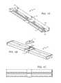
- FIGS. 1A-1Eare bottom perspective, top exploded perspective, top, side, and end views of a light fixture according to an embodiment of the present invention.
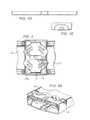
- FIG. 2is a top view of a mount bracket according to an embodiment of the present invention.
- FIGS. 3A and 3Bare end cut-away view of a light fixture according to an embodiment of the present invention and a magnified perspective cut-away view of a section of a light fixture according to an embodiment of the present invention.
- FIGS. 4A and 4Bare magnified perspective cut-away views of sections of light fixtures according to an embodiment of the present invention.
- FIG. 5is a perspective view of a light fixture according to an embodiment of the present invention mounted to a ceiling.
- FIG. 6is a perspective view of a light fixture according to an embodiment of the present invention suspended from a ceiling.
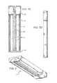
- FIGS. 7A-Eare bottom perspective, top exploded perspective, top, side, and end views of a light fixture according to an embodiment of the present invention.
- FIG. 8is a perspective view of a light fixture according to an embodiment of the present invention mounted to a ceiling.
- FIGS. 9A-Gare bottom perspective, top perspective, bottom, top, side, end, and top perspective exploded views of a light fixture according to an embodiment of the present invention.
- FIG. 10is a bottom perspective view of a light fixture according to an embodiment of the present invention.
- FIG. 11is a perspective transverse cut-away view and a perspective longitudinal cut-away view of a light fixture according to an embodiment of the present invention.
- FIG. 12is a perspective longitudinal cut-away view of a light fixture according to an embodiment of the present invention.
- FIG. 13is a perspective view of a light fixture according to an embodiment of the present invention mounted to a ceiling.
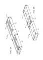
- FIGS. 14A and 14Bare perspective views of a light fixture according to an embodiment of the present invention.
- Embodiments of the present inventionprovide a troffer-style fixture that is particularly well-suited for use with solid state light sources, such as LEDs.
- the troffercomprises a light engine unit that is surrounded on its perimeter by a reflective pan.
- a back reflectordefines a reflective surface of the light engine.
- a heat sinkis disposed proximate to the back reflector.
- one or more lens platesextend from the heat sink out to the back reflector.
- a portion of the heat sinkis exposed to the ambient environment outside of the cavity.
- the portion of the heat sink inside the facing the back reflectorfunctions as a mount surface for the light sources, creating an efficient thermal path from the sources to the ambient.
- One or more light sources disposed along the heat sink mount surfaceemit light into the interior where it can be mixed and/or shaped before it is emitted from the troffer as useful light.
- Troffers emitting in this wayare known as indirect troffers or fixtures (used interchangeably herein).
- Some indirect fixturesare described in U.S. patent application Ser. No. 12/873,303 to Edmond et al. and entitled “Troffer-Style Fixture,” which is commonly assigned with the present application and fully incorporated by reference herein in its entirety.
- LED sourcesare relatively intense when compared to other light sources, they can create an uncomfortable working environment if not properly diffused.
- Fluorescent lamps using T8 bulbstypically have a surface luminance of around 21 lm/in 2 .
- Many high output LED fixturescurrently have a surface luminance of around 32 lm/in 2 .
- Some embodiments of the present inventionare designed to provide a surface luminance of not more than approximately 32 lm/in 2 .
- Other embodimentsare designed to provide a surface luminance of not more than approximately 21 lm/in 2 .
- Still other embodimentsare designed to provide a surface luminance of not more than approximately 12 lm/in 2 .
- Embodiments of the present inventionare designed to efficiently produce a visually pleasing output. Some embodiments are designed to emit with an efficacy of no less than approximately 65 lm/W. Other embodiments are designed to have a luminous efficacy of no less than approximately 76 lm/W. Still other embodiments are designed to have a luminous efficacy of no less than approximately 90 lm/W.
- One embodiment of a fixtureis designed to achieve at least 88% total optical efficiency with a maximum surface luminance of not more than 32 lm/in 2 with a maximum luminance gradient of not more than 5:1. Total optical efficiency is defined as the percentage of light emitted from the light source(s) that is actually emitted from the fixture.
- Other similar embodimentsare designed to achieve a maximum surface luminance of not more than 24 lm/in 2 .
- Still other similar embodimentsare designed to achieve a maximum luminance gradient of not more than 3:1.
- One embodiment of a fixtureincludes a chamber portion which can house, for example, circuitry and wire connections.
- This chamber portioncan be placed in the middle of the fixture and cooperate with the heat sink. By placing the chamber portion in the middle of the fixture, smaller lenses can be used to reduce costs.
- a fixtureincludes an elongated housing and heat sink.
- the chamber portioncan be placed either in the center of the fixture or on one end.
- One or more light sourcesare placed on a mount surface of the heat sink such that the light sources are facing the back reflector.
- the fixturecan include one or more lenses, either on the heat sink over the light sources of extending from the heat sink to the back reflector (such that light passes through the lenses after reflecting off of the back reflector).
- the fixturecan also include a flame barrier over the light sources and on the heat sink.
- the light sourcescan have a portion that protrudes through the flame barrier to increase efficiency.
- a fixturecan be mounted to a ceiling using a universal mount bracket.
- the mount bracketcan cooperate with the fixture housing, for example, a hook-and-flange system.
- the fixturecan be suspended from a ceiling.
- One embodiment of a fixture according to theincludes a chamber portion running longitudinally such that the fixture has two mount surfaces, each with its own internal cavity and back reflector section.
- Embodiments of the present inventionare described herein with reference to conversion materials, wavelength conversion materials, phosphors, phosphor layers and related terms. The use of these terms should not be construed as limiting. It is understood that the use of the term phosphor, or phosphor layers is meant to encompass and be equally applicable to all wavelength conversion materials.
- the term “source”can be used to indicate a single light emitter or more than one light emitter functioning as a single source.
- the termmay be used to describe a single blue LED, or it may be used to describe a red LED and a green LED in proximity emitting as a single source.
- the term “source”should not be construed as a limitation indicating either a single-element or a multi-element configuration unless clearly stated otherwise.
- coloras used herein with reference to light is meant to describe light having a characteristic average wavelength; it is not meant to limit the light to a single wavelength.
- light of a particular colore.g., green, red, blue, yellow, etc.
- Embodiments of the inventionare described herein with reference to cross-sectional view illustrations that are schematic illustrations. As such, the actual thickness of elements can be different, and variations from the shapes of the illustrations as a result, for example, of manufacturing techniques and/or tolerances are expected. Thus, the elements illustrated in the figures are schematic in nature and their shapes are not intended to illustrate the precise shape of a region of a device and are not intended to limit the scope of the invention.
- FIGS. 1A-1Eare a bottom perspective, exploded top perspective, bottom, side, and end views of a troffer or fixture (used interchangeably herein) according to the present invention.
- the troffer 100may be fit-mounted within a ceiling, mounted to a ceiling, or suspended.
- the FIG. 1A view of the troffer 100is from an area underneath the troffer, i.e., the area that would be lit by light sources housed within the troffer.
- the troffer 100can have various specifications. For example, a 20′′ long troffer can have a width of 5.75′′ and height of 2.0′′ and weigh less than 2 pounds, and can emit light with a color temperature of 2700K and CRI of 80 when operating at 120-277V/60 Hz and 40 W.
- a 40′′ troffercan have these same specifications but with a weight of about 3 pounds. Troffers with other dimensions, such as two foot long and four foot long troffers, are also possible. Troffers with these and similar dimensions are elongated and have elongated housings. These specifications are purely exemplary, as many different variations of fixtures according to the present invention are possible.
- the troffer 100can comprise an elongated housing 102 .
- the elongated housing 102can be extruded from a plastic material such as polycarbonate, or it can be made of many other suitable materials including, but not limited to, metals.
- the housing 102has an interior surface that can serve as a back reflector 104 , which can be a highly reflective material and/or be textured (e.g., using micro-mixing optics) to improve color mixing and reduce imaging from the light sources.
- An elongated heat sink 106runs longitudinally down the center of the troffer. In some embodiments, the heat sink 106 can provide mechanical support for the fixture.
- the heat sinkshould be fabricated from a highly thermally conductive material such as, for example, aluminum.
- a chamber portion 108is designed to cooperate with the heat sink 106 .
- the heat sink 106is continuous through the chamber portion 108 such that the heat sink 106 spans the length of the housing 102 . This provides for increased heat dissipation from the chamber portion 108 , as well ease of manufacture and lower cost. In other embodiments the heat sink is not continuous through the chamber portion.
- the chamber portion 108is located in the center of the fixture 100 , although in other embodiments it may not be in the center and can be anywhere along the fixture 100 .
- placing the chamber portion 108 in the center of the fixture 100 as opposed to on one end of the fixture 100allows for the use of two smaller lenses covering half of the fixture as opposed to one large lens running the entire length of the fixture, which can decrease manufacturing and tooling costs.
- the chamber portion 108provides an internal space for disposing power and driver circuitry and/or wiring connection.
- the chamber portion 108protects these elements from outside elements and also helps to prevent shock by users during installation.
- End caps 110can be disposed on the ends of the housing 102 .
- the end caps 110are separate pieces, although other embodiments comprise integral end caps or no end caps.
- the housing 102is shaped to define an interior surface comprising a back reflector 104 , although in other embodiments the back reflector 104 is separate from the interior surface of the housing 102 .
- the heat sink 106is mounted proximate to the back reflector 104 .
- the heat sink 106comprises a mount surface that faces toward the back reflector 104 .
- the mount surfaceprovides an area where the light sources (not shown) can be mounted to face the back reflector 104 .
- the mount surfaceis flat and the light sources face the center region of the back reflector, although angled mount surfaces are possible and light sources facing other portions of the back reflector are possible.
- the light sourcesmay be mounted to a mount such as a metal core board, FR4 board, PCB, or a metal strip (e.g., aluminum) which can then be mounted to a separate heat sink using, for example, thermal paste, adhesive, and/or screws.
- a separate light strip or mountis not used.
- Some embodimentscomprise separate or integral heat sinks with fins, while some do not have fins.
- the back reflector 104can be designed to have several different shapes to perform particular optical functions, including but not limited to color mixing and beam shaping.
- the back reflector 104should be highly reflective in the wavelength ranges of the light sources.
- the back reflector 104can be 93% reflective or higher.
- the back reflector 104can be at least 95% reflective, at least 97% reflective, or at least 99% reflective.
- Reflectors according to the present inventioncan comprise many different materials.
- the back reflector 104comprises a diffuse reflective surface.
- a reflectorcan comprise a polymeric or film material designed to reflect light emitted from an emitter on a light bar.
- the reflector surfacecan be white.
- the reflectorcomprises a white plastic, such as white plastic sheet(s) or one or more layers of microcellular polyethylene terephthalate (“MCPET”), and in some embodiments the reflector comprises white paper.
- reflectorcan comprise a white film, such as White97TM Film available from WhiteOptics, LLC, of New Castle, Del.
- the reflectorcan comprise metal, including but not limited to WhiteOpticsTM Metal, available from WhiteOptics, LLC, or similar.
- the reflectorcan be a plastic or metal device that is coated or painted with a reflective material, or another base material coated with a reflective material. Materials can also include specular reflectors which can help directly control the angle of redirected light rays, Lambertian reflectors, and combinations of diffuse, specular, and Lambertian reflectors.
- Diffuse reflectorshave the inherent capability to mix light from solid state light sources having different spectra (i.e., different colors). These diffuse reflectors are particularly well-suited for multi-source designs where two or more different spectra are to be mixed to produce a desired output color point. For example, LEDs emitting blue light may be used in combinations with LEDs emitting yellow (or blue-shifted yellow) light to yield a white light output, or LEDs emitting both blue and blue-shifted light can be used and yield a white light output.
- a diffuse reflectorcan eliminate the need for additional spatial color-mixing schemes that can introduce lossy elements into the system, although in some embodiments it may be desirable to use a diffuse reflector in combination with other diffusive elements.
- the back reflector 104is coated with a diffusive material. In some embodiments, the back reflector 104 can be coated with a phosphor material that converts the wavelength of at least some of the light from the light sources to achieve a light output of the desired color point.
- the back reflector 104comprises a diffuse white reflective material.
- a diffuse white reflective materialBy using this or a similar material and positioning light sources to emit first toward the back reflector 104 , several design goals are achieved. For example, the back reflector 104 performs a color-mixing function, effectively doubling the mixing distance and greatly increasing the surface area of the source. Additionally, the surface luminance is modified from bright, uncomfortable point sources to a much larger, softer diffuse reflection.
- a diffuse white materialalso provides a uniform luminous appearance in the output.
- Harsh surface luminance gradients(max/min ratios of 10:1 or greater) that would typically require significant effort and heavy diffusers to ameliorate in a traditional direct view optic can be managed with much less aggressive (and lower light loss diffusers) to achieve max/min ratios of 5:1, 3:1, or even 2:1.
- the back reflector 104can also be textured to, among other functions, improve color mixing and reduce imaging from the light sources.
- the back reflector 104comprises micro-mixing optics.
- the texturingcan be imparted to the reflector 104 by roughening the interior or exterior surface of the reflector 104 .
- polycarbonatecan be used.
- the intensity of the rougheningcan vary spatially relative to the center of the reflector and/or the positioning of the light source.
- the rougheningcan be accomplished in a number of different ways, regardless of whether the reflector is initially made by extrusion or by some other method. Textured reflectors are described in U.S. patent application Ser. No.
- the reflector 104 when texturedcan provide color mixing and reduce color hot spots and reflections in a light fixture that uses multiple color emitters.
- some fixturesinclude blue-shifted yellow plus red (BSY+R) LED systems, wherein the LED light source includes at least two groups of LEDs, wherein one group emits light having a dominant wavelength from 435 to 490 nm, and another group emits light having a dominant wavelength from 600 to 640 nm.
- one groupcan be packaged with a phosphor, which, when excited, emits light having a dominant wavelength from 540 to 585 nm.
- the first groupemits light having a dominant wavelength from 440 to 480 nm
- the second groupemits light having a dominant wavelength from 605 to 630 nm
- the trofferemits light having a dominant wavelength from 560 to 580 nm.
- thin extruded high reflectivity PC platescan have a pattern imprinted as part of the extrusion process, and the plates can be pressed onto an un-textured extruded PC back reflector substrate.
- an imprinted patternis a prismatic pattern, which can include repeated prismatic elements extending in all directions. Such a pattern can also be used in a lens material.
- Another example of an imprinted patternis a cut keystone pattern.
- the entire reflectorcan be extruded with an imprinted pattern on the inside or bottom surface of the reflector. Either type of imprinting can be accomplished with a textured drum as part of the extrusion process.
- a roughening patterncan also be applied by roughening a reflector or a plate to be pressed on to a reflector substrate with sand blasting, sanding, or another roughening technology. Textured reflectors are described in detail in U.S. patent application Ser. No. 13/345,215 to Lu et al.
- the back reflector 104has a cross-section that is substantially parabolic on its sides with a flat portion connecting these two portions; however, many other shapes are possible. Also as shown in FIGS. 1B and 1E , the troffer 100 can be designed to have a reduced height profile, such as having a total height of about 2′′ or less. The shape of the back reflector 104 should be chosen to produce the appropriate reflective profile for an intended output.
- a typical solid state lighting fixturewill incorporate a heat sink that sits above the ceiling plane to dissipate conducted LED heat into the environment. Temperatures above office and industrial ceilings in a non-plenum ceiling regularly reach 35° C. As discussed herein, the bottom portion of the heat sink 106 , including the fin structures if present, can be exposed to the air in the room beneath the troffer 100 .
- An exposed heat sink 106can be advantageous for several reasons. For example, air temperature in a typical office room is much cooler than the air above the ceiling, obviously because the room environment must be comfortable for occupants; whereas in the space above the ceiling, cooler air temperatures are much less important. Additionally, room air is normally circulated, either by occupants moving through the room or by air conditioning. The movement of air throughout the room helps to break the boundary layer, facilitating thermal dissipation from the heat sink. Also, a room-side heat sink configuration prevents improper installation of insulation on top of the heat sink as is possible with typical solid state lighting applications in which the heat sink is disposed on the ceiling-side. This guard against improper installation can eliminate a potential fire hazard.
- the troffer 100is designed to be mounted to or within a ceiling.
- the chamber portion 108can be designed to cooperate with a mount bracket 112 .
- the mount bracket 112can include hook features that snap into place on the underside of a housing flange for easy installation.
- the mount bracket 112may be mounted directly to a J-box on a ceiling. After the mount bracket 112 is mounted to the ceiling, the chamber portion 108 can be snapped into place using the hook-and-flange structure. In some embodiments, the housing 102 can then be slid from side to side for fine adjustment of position.
- a hook-and-flange attachment systemis described herein, many other attachment systems are possible.
- the chamber portion 108can include a hole 114 through which connection wires can pass.
- the mount bracket 112can also have a corresponding hole.
- FIG. 2is a close-up top view of a mount bracket 212 attached to a fixture 200 .
- the fixture 200includes a housing 202 and a chamber portion 208 , and the chamber portion 208 has a center hole 214 which can be used to either feed wiring or connect to the mount bracket 212 .
- the mount bracket 212includes hook portions 216 which can lock into flanges on the underside of the chamber portion 208 or, alternatively, another section of the housing 202 .
- Various holes and slots 212 a in the mount bracket 212can be used to feed wiring into the chamber portion 208 to power the internal drive circuitry, emitters, and other electronic components.
- the mount bracket 212is a universal mount bracket and can fit junction boxes (“J-boxes”) of many different shapes sizes, including but not limited to circular and octagonal and 2′′ and 4′′.
- FIG. 3Ais a cut-away perspective view of a fixture 300 according to the present invention, with the cut plane within a chamber portion 308 .
- FIG. 3Bis a cut-away end view of the fixture 300 along the same cut plane. The cut-away view exposes the interior space 320 created by the chamber portion 308 of a housing 302 .
- a heat sink 306runs through the space, with light emitters such as LEDs 324 mounted on a lighting strip 322 , which is itself mounted on a mount surface of the heat sink 306 . In other embodiments, the light emitters 324 are mounted directly on the heat sink 306 .
- Electrical componentsmay also be disposed within the interior space 320 , such as connected to a circuit mount board 330 which is mounted within the space 320 .
- Some examples of electrical components that can be included in embodiments of the present inventioninclude power circuitry and drive circuitry including, for example, AC/DC driver circuitry and DC/DC driver circuitry, to name a few.
- a driver circuitmay comprise an AC to DC converter, a DC to DC converter, or both.
- the driver circuitcomprises an AC to DC converter and a DC to DC converter both of which are located inside the interior space 320 .
- the AC to DC conversionis done remotely (i.e., outside the optical chamber), and the DC to DC conversion is done at the control circuit inside the optical chamber.
- only AC to DC conversionis done at a control circuit within the interior space 320 .
- a mount bracket 312is connected to a chamber portion 308 using a hook-and-flange structure.
- the bracket 312comprises bracket hooks 326 while the chamber portion 308 comprises flanges 332 .
- the heat sink 306is connected to the chamber portion 308 using a flange-and-slot structure with flanges 332 and slots 334 .
- the flanges 332 and slots 334run the entire length of the chamber portion 308 .
- connection systems between the bracket 312 and chamber portion 308 and between the heat sink 306 and the chamber portion 308 and/or housing 302are possible, such as screws and/or adhesive, for example. Some of these alternate connection systems may be more permanent than hook-and-flange structures.
- the troffermay comprise one or more emitters producing the same color of light or different colors of light.
- a multicolor sourceis used to produce white light.
- white lightFor example, it is known in the art to combine light from a blue LED with wavelength-converted yellow (blue-shifted-yellow or “BSY”) light to yield white light with correlated color temperature (CCT) in the range between 5000K to 7000K (often designated as “cool white”).
- BSYwavelength-converted yellow
- CCTcorrelated color temperature
- Both blue and BSY lightcan be generated with a blue emitter by surrounding the emitter with phosphors that are optically responsive to the blue light. When excited, the phosphors emit yellow light which then combines with the blue light to make white.
- saturated lightbecause the blue light is emitted in a narrow spectral range it is called saturated light.
- the BSY lightis emitted in a much broader spectral range and, thus, is called unsaturated light.
- RGB schemesmay also be used to generate various colors of light.
- an amber emitteris added for an RGBA combination.
- the previous combinationsare exemplary; it is understood that many different color combinations may be used in embodiments of the present invention. Several of these possible color combinations are discussed in detail in U.S. Pat. No. 7,213,940 to Van de Ven et al., which is commonly assigned with the present application and fully incorporated by reference herein in its entirety.
- the emittersare solid state emitters such as LEDs or LED packages. Many different LEDs can be used such as those commercially available from Cree Inc., under its DA, EZ, GaN, MB, RT, TR, UT and XT families of LED chips. Further, many different types of LED packages can be used in embodiments of the present invention. Some types of chips and packages are generally described in U.S. patent application Ser. No. 12/463,709 to Donofrio et al., entitled “Semiconductor Light Emitting Diodes Having Reflective Structures and Methods of Fabricating Same,” U.S. patent application Ser. No.
- the emitterscan emit many different colors of light, with preferred emitters emitting white light (or chips emitting blue light, part of which is converted to yellow light to form a white light combination).
- a package that can be used in a fixture according to the present inventioncomprises a substantially box shaped encapsulant, which results in a package emission that is broader than Lambertian. Many of these packages are shown and described in U.S. patent application Ser. No. 13/649,067 to Lowes et al., which is commonly assigned with the present application and fully incorporated by reference herein in its entirety. It is understood that in some embodiments the LED can be provided following removal of its growth substrate. In other embodiment, the LED's growth substrate can remain on the LED, with some of these embodiments having a shaped or textured growth substrate. In some embodiments when the LED's growth substrate remains on the LED, the LED is flip-chip mounted onto a light strip or mount surface.
- the LEDscan comprise a transparent growth substrate such as silicon carbide, sapphire, GaN, GaP, etc.
- the LED chipscan also comprise a three dimensional structure and in some embodiments, the LEDs can have structure comprising entirely or partially oblique facets on one or more surfaces of the chip.
- the light emitters 324are LED chips and/or packages which can, in some embodiments, have an emission pattern that is broader than Lambertian, such as, for example, those described in U.S. patent application Ser. Nos. 13/649,052 and 13/649,067. In another preferred embodiment, these LED chips and/or packages are used in combination with standard Lambertian emitters. In another embodiment, the light emitters 324 are phosphor-coated LEDs such as, for example, those described in U.S. patent application Ser. Nos. 11/656,759 and 11/899,790, both to Chitnis et al.
- the light emitters 324are phosphor-coated LED chips and/or packages with emission patterns that are broader than Lambertian. In another preferred embodiment, these LEDs emit in the blue spectrum and are covered in a yellow phosphor, resulting in a white emission. In another embodiment the light emitters 324 have a Lambertian emission profile.
- FIG. 4Ais a perspective cut-away view of the fixture 400 from a bottom side angle, with the cut-plane along a portion of a housing 402 outside of a chamber portion 408 .
- the fixture 400also includes chamber portion walls 409 , which enclose an interior space (not shown) similar to that shown in FIGS. 3A and 3B .
- the heat sink 406is connected to the chamber portion 408 using a flange-and-slot system similar to that shown in FIGS. 3A and 3B .
- the fixture 400also includes a lens 440 .
- the lens 440can comprise a diffusive material to help with color mixing.
- the lenscan also function to protect the consumer from coming into contact with high voltage elements such as LEDs.
- the lens 440has a semi-circular cross-section and is mounted to the heat sink 406 over the emitters (not shown). While the lens 440 is shown mounted on the heat sink 406 , many other arrangements are possible.
- a lens platewhich will be discussed in further detail with regard to FIG. 6 , could be mounted between a housing 402 and the heat sink 406 using, for example, slots 434 , such that the slots 434 connect to the chamber portion 408 and connect to a lens in areas outside of the chamber portion 408 .
- lensescan be textured and/or include microlens structures, for example. Textured lenses and lenses with microlens structures are discussed in detail in U.S. patent application Ser. No. 13/442,311 to Lu et al.
- FIG. 4Bis a perspective cut-away view of the fixture 401 from a bottom side angle.
- the fixture 401comprises many of the same components as the fixture 400 , and corresponding reference numerals are used to indicate corresponding elements.
- the fixture 401comprises a flame barrier 441 which is required to cover high voltage emitters on a light strip 422 .
- the flame barrier 441can be made of, for example, glass or a UL94 5 VA rated transparent plastic.
- the flame barrier 441comprises cutouts through which part of the emitter (not shown, but situated similarly to light emitters 324 of FIG. 3 ), such as an LED dome, can protrude, while the flame barrier 441 still covers the high voltage portions of the LED to meet engineering requirements.
- Such embodimentscan help to minimize or even eliminate the optical losses associated with the flame barrier 441 .
- Some embodimentscan comprise both a lens 440 and a flame barrier 441 , and in some embodiments a single element can combine the characteristics of both and/or perform both functions.
- fixtures according to the present inventioncan be mounted to a ceiling. Such an embodiment is shown in FIG. 5 .
- the fixture 500can be mounted to the ceiling using a mount bracket (not shown).
- Fixtures according to the present inventioncan also be mounted within a cavity in the ceiling by various methods, including by using a mount bracket.
- Fixtures according to the present inventioncan also be suspended from a ceiling, such as the fixture 600 , seen in FIG. 6 .
- the fixture 600includes two suspension devices 642 , although any number of suspension devices is possible. In embodiments where wiring is not directly connected to the chamber portion 608 (i.e., an embodiment unlike that of the troffer 100 , where wiring enters the chamber portion 108 through a hole 114 ), wiring can be connected to the chamber portion in a less direct manner.
- wiringcan be connected to the troffer 600 and the chamber portion 608 by running wiring through one or more of the suspension devices 642 , through the housing 602 , and to the chamber portion 608 .
- a suspension devicecan connect directly to the chamber portion 608 , whether the chamber portion 608 is in the center of the fixture 600 or on one end.
- a fixturecan be suspended using simple chains or cords, for example.
- the fixture 600also includes a textured back reflector 640 .
- the back reflector 640can be made of many different materials.
- the texturing on the back reflector 640can comprise materials and manufactured using methods described in U.S. patent application Ser. No. 13/345,215 to Lu et al. and/or U.S. patent application Ser. No. 13/442,311.
- the fixture 600optionally can include lens plates (not shown).
- the lens platescan be mounted between the housing 602 , the heat sink 606 , and/or the chamber portion 608 .
- the lens platescan cooperate with one or more of the housing 602 , the heat sink 606 , or the chamber portion 608 .
- the lens platecan be mounted to the heat sink 606 using, for example, heat sink slots (not shown) similar to the slots 434 shown in FIG. 4 .
- the lens platesare also mounted to the chamber portion 608 and/or one of the end caps 610 , although this is not always necessary.
- Troffers according to the present inventioncan comprise many different types of lens plates.
- Lens platescan serve to provide physical protection to components within the troffer, such as LEDs. Lens plates can achieve this by, for example, preventing physical damage or dust accumulation, which can negatively affect the troffer's emission efficiency, intensity, and/or profile. Lens plates also serve to improve the uniformity of the troffer emission. Depending upon the type of emitters and the reflector used in a troffer, bright “hotspots” of light can sometimes be seen on the reflector above the emitter sources. These hotspots are sometimes undesirable and can negatively affect emission uniformity. Lens plates can help to reduce the appearance of these hotspots to a viewer by spreading the light reflected from these hotspots across a wider viewing area.
- lens platescan help to diffuse light, broaden the troffer's emission profile, focus the troffer's emission profile, and/or create a more uniform appearance.
- Lens platescan be textured in order to achieve one or more of the above goals.
- a lens platecan include facets, or can comprise one or more thin films which have linear or discrete facets or other texturing.
- Other examples of lens plateshave deglaring prisms.
- One embodiment of a lens plate used in a troffer according to the present inventioncomprises extruded acrylic with either a diffuser built into the acrylic or a diffuser film coating.
- Other embodiments of lens plates that can be used in the present inventioninclude diffuse lenses, which scatter all incident light.
- Further embodimentscan comprise acrylics, PMMAs, and/or diffusing additives. Some embodiments can comprise clear acrylics.
- FIGS. 7A-7Eare bottom perspective, top perspective, bottom, side, and end views of another fixture 700 according to the present invention.
- the fixture 700comprises a housing 702 , a back reflector 704 , a heat sink 706 , and two end caps 710 .
- the fixture 700also comprises a chamber portion 708 .
- the heat sink 706is continuous through the chamber portion 708 .
- the chamber portion 708is not in the center of the fixture 700 , but instead at one longitudinal end of the fixture 700 .
- the chamber portion 708is against an end cap 710 a , although some embodiments do not comprise end caps 710 a , 710 b .
- Various holes and slots on the back side of the chamber portion 708are used to feed wiring into the chamber portion 708 to power the internal drive circuitry, emitters, and other electronic components.
- the center hole 714can be used to feed wiring, or can be used to connect the fixture 700 to a mount bracket similar to the mount bracket 212 shown in FIG. 2 .
- the chamber portion 708is on the end of the fixture 700 , in other embodiments it can be anywhere along the fixture 700 .
- the fixture 700comprises a single chamber portion 708
- other embodimentsmay comprise two or more chamber portions, such as one chamber portion at each longitudinal end of a fixture.
- Embodiments similar to the fixture 700can also comprise one or more lenses.
- lensescould occupy the two areas 707 defined by the housing 702 , the heat sink 706 , and the chamber portion 708 , as shown in FIG. 7C .
- a lensis on the heat sink and over any emitters mounted thereon.
- only one lensis needed. The lens can pass below the heat sink 706 so as to traverse the fixture 700 while also occupying the two areas 707 .
- the heat sink 706is on the lens.
- the chamber portion 708provides an internal space for disposing power and driver circuitry and wiring connections.
- the spaceprotects the connections from outside elements and also helps to prevent shock by users during installation.
- the chamber portion 708can be designed to cooperate with a mount bracket such as the mount bracket 112 shown in FIG. 1 .
- the mount bracketcan be mounted directly to a J-box or a ceiling. After the bracket is mounted to a ceiling, the chamber portion 708 can be snapped into place using the hook-and-flange structure.
- the end cap opposite the chamber portion 710 bcan be attached to the ceiling using screws, hooks, wire, cord, or many other attachment mechanisms.
- a troffer 800 similar to the troffer 700is shown mounted to a ceiling in FIG. 8 . In other embodiments, the entire fixture 700 can be suspended from a ceiling, such as with a wire or cord.
- FIGS. 9A-9Gare bottom perspective, top perspective, bottom, top, side, end, and exploded view of another fixture 900 according to the present invention.
- the fixture 900comprises a housing 902 , a back reflector 904 , a heat sink 906 , and two end caps 910 .
- the fixture 900also comprises a chamber portion 908 and a mount bracket 912 .
- the heat sink 906is continuous through the chamber portion 908 .
- the chamber portion 908is in the center of the fixture 900 .
- An embodiment similar to that of the fixture 900can also comprise lenses.
- four lensescan occupy the four areas 907 defined by the housing 902 , the heat sink 906 , and the chamber portion 908 , as shown in FIG. 9C .
- Smaller lensescan be more cost efficient to manufacture than larger lenses.
- utilizing smaller lenses occupying the four areas 907may be more cost effective than utilizing larger lenses occupying the two areas 707 in FIG. 7C .
- FIG. 9Gis an exploded top perspective view of the fixture 900 .
- the chamber portion 908comprises the main housing 952 , the back housing 954 , and electronics 956 housed within the chamber portion 908 .
- the electronicscan include, for example, circuits on a PCB.
- Components of the fixture 900can be attached to one another using various attachment means. As shown in FIG. 9G , one embodiment uses screws 958 as an attachment means. End caps 910 , if present, can also be attached to the main housing 902 using an attachment means such as screws 958 .
- the heat sink 906has a light strip 922 over a portion 906 A of the heat sink 906 .
- the light strip 922includes light emitters or sources 924 .
- FIG. 10is a bottom perspective view of a fixture according to the present invention.
- a fixture 1000can have a length of about 10′′, width of about 17′′, and a height of about 2.5′′ or less or about 2.0′′ or less, although these dimensions are purely exemplary.
- the fixture 1000comprises a housing 1002 , one or more back reflectors 1004 , one or more heat sinks 1006 , and one or more end caps 1010 .
- the chamber portion 1008can run longitudinally from end cap to end cap and parallel with the heat sink 1006 .
- the chamber portion 1008can cooperate with or be on the heat sink 1006 , and in some embodiments the heat sink 1006 dissipates heat generated from components within the chamber portion 1008 .
- FIG. 11is a cut-away perspective view of the fixture 1100 with the cut-plane transverse to the chamber portion 1108 .
- the chamber portion 1108houses electronic components 1108 a .
- the fixture 1100has two internal surfaces, in this case back reflectors 1104 .
- the fixture 1100comprises a heat sink 1106 with two mount surfaces 1106 a and 1106 b .
- the heat sink and one or more mount surfacesare all integral with one another.
- Some other embodimentsmay comprise two or more separate heat sinks, each with its own integral one or more mount surfaces.
- the fixture 1100also comprises a housing 1102 and a chamber portion 1108 .
- This chamber portionis along the top length of the heat sink 1106 .
- the heat sink 1106can provide a path for thermal dissipation from emitters on the mount surfaces 1106 a and 1106 b as well as the chamber portion 1108 .
- Light emitters 1124are mounted on the mount surfaces 1106 a and 1106 b . These light emitters 1124 emit light toward the two back reflectors 1104 .
- the back reflectors 1104are shaped so as to produce the desired fixture light profile. In the embodiment shown the emitters 1124 have a primary emission surface facing straight up. Thus, the back reflectors 1124 are shaped to divert light away from the chamber portion 1108 and toward lens plates 1140 , through which the light will pass.
- the mount surfaces 1106 a and 1106 bcan be angled, such as being angled away from the chamber portion 1108 , and the shape of the back reflectors 1104 can be adjusted accordingly. While the embodiment shown comprises two back reflectors 1104 , other embodiments may comprise a single back reflector with two internal surfaces. For example, the back reflector could pass over the chamber portion 1108 and thus form an internal surface on either side of the chamber portion 1108 .
- the fixture 1100also comprises one or more lens plates 1140 .
- Lens platescan serve to provide physical protection to components within the troffer, such as LEDs. Lens plates can achieve this by, for example, preventing physical damage or dust accumulation, which can negatively affect the troffer's emission efficiency, intensity, and/or profile. Lens plates also serve to improve the uniformity of the troffer emission. Depending upon the type of emitters and the reflector used in a troffer, bright “hotspots” of light can sometimes be seen on the reflector above the emitter sources. These hotspots are sometimes undesirable and can negatively affect emission uniformity. Lens plates can help to reduce the appearance of these hotspots to a viewer by spreading the light reflected from these hotspots across a wider viewing area.
- the light reflected from these hotspotscan be spread across the entire luminaire.
- lens platescan help to diffuse light, broaden the troffer's emission profile, and/or create a more uniform appearance.
- the lens plate 1140comprises a diffusive element.
- a diffusive exit lensfunctions in several ways. For example, it can prevent direct visibility of the sources and provide additional mixing of the outgoing light to achieve a visually pleasing uniform source.
- a diffusive lens platecan introduce additional optical loss into the system.
- a transparent glass lens platecan be used, or the lens plate can be removed entirely.
- scattering particlesmay be included in the lens plate 1140 .
- Some embodimentsmay include a specular or partially specular back reflector. In such embodiments, it may be desirable to use a diffuse lens plate.
- Diffusive elements in the lens plate 1140can be achieved with several different structures.
- a diffusive film inlaycan be applied to the top- or bottom-side surface of the lens plate 1140 . It is also possible to manufacture the lens plate 1140 to include an integral diffusive layer, such as by coextruding the two materials or by insert molding the diffuser onto the exterior or interior surface.
- a clear lensmay include a diffractive or repeated geometric pattern rolled into an extrusion or molded into the surface at the time of manufacture.
- the lens plate materialitself may comprise a volumetric diffuser, such as an added colorant or particles having a different index of refraction, for example.
- Faceted lensescan use bumps or pips to scatter light in a predictable manner.
- Faceted lensescan comprise prisms, such as deglaring and/or linear prisms.
- a lens platecan also comprise films with linear or discrete facets. The properties of such films can be enhanced if a plurality of films is stacked. Such films can be on the troffer side of the lens plate, emission side of the lens plate, or both.
- a lenscan be used to optically shape the outgoing beam with the use of microlens structures, for example. Microlens structures are discussed in detail in U.S. patent application Ser. No. 13/442,311.
- FIG. 12is a cut-away perspective view of the fixture 1200 with the cut-plane longitudinal along the chamber portion 1208 .
- the chamber portion 1208does not run the entire length of the troffer 1200 .
- the chamber portionruns the entire length of the troffer.
- the housing 1202comprises a portion 1202 a that is over the reflector 1204 .
- the reflector 1204can serve as the back surface of the troffer 1200 .
- FIG. 13is a perspective view of a troffer 1300 similar to the troffers 1100 and 1200 shown mounted to a ceiling.
- the entire fixture 1300can be suspended from a ceiling, such as with a wire or cord.
- multiple fixturese.g., one or more of the fixture 100 , fixture 700 , and/or fixture 900
- the end caps of the fixture ends being joined (if present)are removed and an attachment means is used to connect two fixtures.
- attachment meansinclude, but are not limited to, a joiner plate, end caps with incorporated attachment mechanisms, and double-sided end caps.
- fixturescan have integral attachment means.
- a fixturecan have male attachment means on one end and female attachment means on the other end.
- FIG. 14shows an embodiment of two fixtures 1400 , 1410 similar in many respects to the fixture 900 from FIG. 9 , and a joiner structure comprising a sleeve 1420 and a mount plate 1430 .
- Each of the fixtures 1400 , 1410has had one end cap removed.
- the mount plate 1430is attached using screws, for example, to the fixtures 1400 , 1410 , and the sleeve 1420 wraps around to cover the interface.
- Sleeves contoured to match the backsides of fixturesare also possible, as are joiner structures without sleeves.
- An extended fixture 1450comprising the two smaller fixtures 1400 , 1410 and the joiner structure comprising the sleeve 1420 and mount plate 1430 , is shown in FIG. 14B . Additional fixtures may be added to the ends of the extended fixture 1450 in either direction to create an extended fixture having a particular desired length. Extended fixtures are possible for fixtures using any type of mount system, including but not limited to ceiling mounted, surface mounted, wall mounted, pendant mounted
Landscapes
- Engineering & Computer Science (AREA)
- General Engineering & Computer Science (AREA)
- Microelectronics & Electronic Packaging (AREA)
- Non-Portable Lighting Devices Or Systems Thereof (AREA)
- Arrangement Of Elements, Cooling, Sealing, Or The Like Of Lighting Devices (AREA)
Abstract
Description
Claims (26)
Priority Applications (2)
| Application Number | Priority Date | Filing Date | Title |
|---|---|---|---|
| US13/834,605US9188290B2 (en) | 2012-04-10 | 2013-03-15 | Indirect linear fixture |
| CN201310123657.2ACN103423666B (en) | 2012-04-10 | 2013-04-10 | Lamps and lanterns |
Applications Claiming Priority (3)
| Application Number | Priority Date | Filing Date | Title |
|---|---|---|---|
| US201261622482P | 2012-04-10 | 2012-04-10 | |
| US201261705585P | 2012-09-25 | 2012-09-25 | |
| US13/834,605US9188290B2 (en) | 2012-04-10 | 2013-03-15 | Indirect linear fixture |
Publications (2)
| Publication Number | Publication Date |
|---|---|
| US20130286637A1 US20130286637A1 (en) | 2013-10-31 |
| US9188290B2true US9188290B2 (en) | 2015-11-17 |
Family
ID=49477110
Family Applications (1)
| Application Number | Title | Priority Date | Filing Date |
|---|---|---|---|
| US13/834,605Active2034-01-18US9188290B2 (en) | 2012-04-10 | 2013-03-15 | Indirect linear fixture |
Country Status (2)
| Country | Link |
|---|---|
| US (1) | US9188290B2 (en) |
| CN (1) | CN103423666B (en) |
Cited By (17)
| Publication number | Priority date | Publication date | Assignee | Title |
|---|---|---|---|---|
| US20150285469A1 (en)* | 2014-04-04 | 2015-10-08 | Valerica Grigore | Linear lighting system, manufacturing and methods to configure the same |
| US9927103B2 (en)* | 2014-05-22 | 2018-03-27 | Feit Electric Company, Inc. | Flush mount lighting fixture |
| US9995444B2 (en) | 2011-10-17 | 2018-06-12 | Ecosense Lighting Inc. | Linear LED light housing |
| US10047937B2 (en) | 2016-06-29 | 2018-08-14 | Feit Electric Company, Inc. | Lighting fixture mounting systems |
| US10113718B2 (en) | 2014-04-23 | 2018-10-30 | General Led Opco, Llc | Retrofit system and method for replacing linear fluorescent lamp with LED modules |
| US10465871B2 (en) | 2014-05-22 | 2019-11-05 | Feit Electric Company, Inc. | Multi-configurable light emitting diode (LED) flat panel lighting fixture |
| US10634320B2 (en) | 2016-06-29 | 2020-04-28 | Feit Electric Company, Inc. | Lighting fixture mounting systems |
| US10989372B2 (en) | 2017-03-09 | 2021-04-27 | Ecosense Lighting Inc. | Fixtures and lighting accessories for lighting devices |
| US11022279B2 (en) | 2016-03-08 | 2021-06-01 | Ecosense Lighting Inc. | Lighting system with lens assembly |
| US11028980B2 (en) | 2013-10-30 | 2021-06-08 | Ecosense Lighting Inc. | Flexible strip lighting apparatus and methods |
| US11041609B2 (en) | 2018-05-01 | 2021-06-22 | Ecosense Lighting Inc. | Lighting systems and devices with central silicone module |
| US11047553B2 (en)* | 2017-10-25 | 2021-06-29 | Nicor, Inc. | Low profile large area luminaire |
| US20210285626A1 (en)* | 2020-03-12 | 2021-09-16 | Abl Ip Holding Llc | Mounting systems for luminaires |
| US11296057B2 (en) | 2017-01-27 | 2022-04-05 | EcoSense Lighting, Inc. | Lighting systems with high color rendering index and uniform planar illumination |
| US11353200B2 (en) | 2018-12-17 | 2022-06-07 | Korrus, Inc. | Strip lighting system for direct input of high voltage driving power |
| US20230358390A1 (en)* | 2020-05-15 | 2023-11-09 | HLI Solutions, Inc. | Light fixture connection system and optic holder |
| US12388056B1 (en) | 2017-01-27 | 2025-08-12 | Korrus, Inc. | Linear lighting systems and processes |
Families Citing this family (31)
| Publication number | Priority date | Publication date | Assignee | Title |
|---|---|---|---|---|
| US8322881B1 (en)* | 2007-12-21 | 2012-12-04 | Appalachian Lighting Systems, Inc. | Lighting fixture |
| USD696449S1 (en) | 2013-03-14 | 2013-12-24 | Lsi Industries, Inc. | Lighting |
| US9127826B2 (en) | 2013-03-14 | 2015-09-08 | Lsi Industries, Inc. | Indirect lighting luminaire |
| USD733952S1 (en)* | 2013-03-15 | 2015-07-07 | Cree, Inc. | Indirect linear fixture |
| US10788177B2 (en) | 2013-03-15 | 2020-09-29 | Ideal Industries Lighting Llc | Lighting fixture with reflector and template PCB |
| USD747541S1 (en)* | 2013-03-20 | 2016-01-12 | Phoenix Contact Gmbh & Co. Kg | LED lamp |
| US20140292198A1 (en)* | 2013-03-28 | 2014-10-02 | American Machine Vision Llc | Multiple application led illumination system |
| US9133981B2 (en)* | 2013-04-15 | 2015-09-15 | Pendant Systems Manufacturing Co. | Hanger system for suspendible illuminated fixtures |
| CA158835S (en)* | 2013-07-15 | 2014-11-17 | Cooper Crouse Hinds Gmbh | Led-module |
| USD732225S1 (en) | 2013-12-09 | 2015-06-16 | Kenall Manufacturing Company | Lighting fixture |
| TWI521172B (en)* | 2014-01-17 | 2016-02-11 | 雷笛揚照明股份有限公司 | Lamp |
| USD749257S1 (en)* | 2014-03-03 | 2016-02-09 | Oldenburg Group Incorporated | Lighting unit |
| TWD163988S (en)* | 2014-04-01 | 2014-11-01 | 東貝光電科技股份有限公司 | LED lamps |
| USD759874S1 (en)* | 2014-05-06 | 2016-06-21 | Lsi Industries, Inc. | Lighting |
| US12372219B2 (en)* | 2014-05-30 | 2025-07-29 | Cree Lighting Usa Llc | LED luminaire with a cavity, finned interior, and a curved outer wall extending from a surface on which the light source is mounted |
| USD780973S1 (en)* | 2014-07-30 | 2017-03-07 | Orion Energy Systems, Inc. | Light fixture |
| USD780974S1 (en)* | 2014-10-08 | 2017-03-07 | Orion Energy Systems, Inc. | Light fixture |
| US10690305B2 (en)* | 2014-10-28 | 2020-06-23 | Ideal Industries Lighting Llc | Edge lit fixture |
| EP3224539A4 (en)* | 2014-11-25 | 2018-08-15 | Wayne Bliesner | Optimization of led lighting system operating at low current levels |
| USD792000S1 (en)* | 2015-04-29 | 2017-07-11 | Chad Burroughs | Lighting apparatus |
| WO2017029147A1 (en)* | 2015-08-20 | 2017-02-23 | Philips Lighting Holding B.V. | Luminaire and luminaire manufacturing method |
| USD780364S1 (en)* | 2015-09-28 | 2017-02-28 | Focal Point, Llc | Light fixture |
| USD773098S1 (en)* | 2015-09-28 | 2016-11-29 | Focal Point, Llc | Light fixture |
| USD780976S1 (en)* | 2015-09-28 | 2017-03-07 | Focal Point, Llc | Light fixture |
| US20180360234A1 (en)* | 2015-11-30 | 2018-12-20 | Andrew Helmut Eichler | Modular Display System For Displaying Models |
| USD818626S1 (en)* | 2016-11-17 | 2018-05-22 | Samjin Lnd Co., Ltd | Flood light |
| CN107965713A (en)* | 2017-12-06 | 2018-04-27 | 南京京泽照明科技有限公司 | A kind of linear explosion suppression type explosion-preventing lamp |
| US11029001B2 (en)* | 2019-08-21 | 2021-06-08 | RAB Lighting Inc. | Apparatuses and methods for changing lighting fixture dimensions |
| US11897390B2 (en)* | 2019-11-27 | 2024-02-13 | Harman International Industries, Incorporated | Techniques for constructing and controlling a vehicle light assembly |
| US20230161127A1 (en)* | 2020-04-15 | 2023-05-25 | CommScope Connectivity Belgium BV | Device and method for sealing cables in telecommunications enclosures |
| US11255521B1 (en)* | 2020-12-02 | 2022-02-22 | Abl Ip Holding Llc | Linear light fixture |
Citations (75)
| Publication number | Priority date | Publication date | Assignee | Title |
|---|---|---|---|---|
| US4946547A (en) | 1989-10-13 | 1990-08-07 | Cree Research, Inc. | Method of preparing silicon carbide surfaces for crystal growth |
| US5200022A (en) | 1990-10-03 | 1993-04-06 | Cree Research, Inc. | Method of improving mechanically prepared substrate surfaces of alpha silicon carbide for deposition of beta silicon carbide thereon and resulting product |
| USRE34861E (en) | 1987-10-26 | 1995-02-14 | North Carolina State University | Sublimation of silicon carbide to produce large, device quality single crystals of silicon carbide |
| US5690415A (en) | 1995-11-29 | 1997-11-25 | Stylmark, Inc. | Display light |
| US5823663A (en) | 1996-10-21 | 1998-10-20 | National Service Industries, Inc. | Fluorescent troffer lighting fixture |
| US5951150A (en) | 1997-09-11 | 1999-09-14 | Eaton Corporation | Display system |
| US6210025B1 (en) | 1999-07-21 | 2001-04-03 | Nsi Enterprises, Inc. | Lensed troffer lighting fixture |
| US6536924B2 (en) | 2001-02-28 | 2003-03-25 | Jji Lighting Group, Inc. | Modular lighting unit |
| US6667451B1 (en) | 2003-03-20 | 2003-12-23 | Eaton Corporation | Push button assembly |
| US6739734B1 (en) | 2003-03-17 | 2004-05-25 | Ultimate Presentation Sytems, Inc. | LED retrofit method and kit for converting fluorescent luminaries |
| US20040240214A1 (en) | 2003-05-28 | 2004-12-02 | Hubbell Incorporated. | Light fixture having air ducts |
| US6914194B2 (en) | 2003-10-29 | 2005-07-05 | Ben Fan | Flexible LED cable light |
| US20050146867A1 (en) | 2003-12-31 | 2005-07-07 | Kassay Charles E. | Fluorescent lighting fixtures with controlled uplight capability |
| US20060050505A1 (en) | 2002-05-28 | 2006-03-09 | Kenall Manufacturing Company | Selectively-extendable modular lighting fixture and method |
| US7213940B1 (en) | 2005-12-21 | 2007-05-08 | Led Lighting Fixtures, Inc. | Lighting device and lighting method |
| US7217023B2 (en) | 2002-08-01 | 2007-05-15 | Toyoda Gosei Co., Ltd. | Linear luminous body and linear luminous structure |
| US20070158668A1 (en) | 2005-08-25 | 2007-07-12 | Cree, Inc. | Close loop electrophoretic deposition of semiconductor devices |
| US20080128723A1 (en) | 2006-12-04 | 2008-06-05 | Siew It Pang | Low Thermal Resistance High Power LED |
| US7387410B2 (en) | 2004-09-07 | 2008-06-17 | C.E.I.T. Corp. | Luminaire assembly and method |
| US20080173884A1 (en) | 2007-01-22 | 2008-07-24 | Cree, Inc. | Wafer level phosphor coating method and devices fabricated utilizing method |
| US20080179611A1 (en) | 2007-01-22 | 2008-07-31 | Cree, Inc. | Wafer level phosphor coating method and devices fabricated utilizing method |
| US20080258130A1 (en) | 2007-04-23 | 2008-10-23 | Bergmann Michael J | Beveled LED Chip with Transparent Substrate |
| US20080314944A1 (en) | 2007-06-21 | 2008-12-25 | Cheng-Yu Tsai | Assembly for fixing and connecting light bar lamp |
| US20090040782A1 (en) | 2007-08-08 | 2009-02-12 | Ledtech Electronics Corp. | Led lighting device |
| US20090046457A1 (en)* | 2007-08-13 | 2009-02-19 | Everhart Robert L | Solid-state lighting fixtures |
| US7540627B2 (en) | 2006-05-08 | 2009-06-02 | Innovative Lighting, Inc. | Channel light system with pivotable connector |
| US20090161356A1 (en) | 2007-05-30 | 2009-06-25 | Cree Led Lighting Solutions, Inc. | Lighting device and method of lighting |
| US20090184333A1 (en) | 2008-01-17 | 2009-07-23 | Foxsemicon Integrated Technology, Inc. | Light emitting diode device |
| US20090207602A1 (en) | 2005-09-06 | 2009-08-20 | Reed Mark C | Linear lighting system |
| US20090212304A1 (en) | 2008-02-22 | 2009-08-27 | Bily Wang | Led chip package structure with multifunctional integrated chips and a method for making the same |
| US20090224265A1 (en) | 2008-03-05 | 2009-09-10 | Bily Wang | LED chip package structure with a high-efficiency heat-dissipating substrate and method for making the same |
| US20090290345A1 (en) | 2008-05-20 | 2009-11-26 | Apl Ip Holding Llc | Enclosures for led circuit boards |
| US20090290348A1 (en) | 2006-04-16 | 2009-11-26 | Peter Van Laanen | Thermal Management Of LED-Based Lighting Systems |
| US20090296381A1 (en) | 2008-06-01 | 2009-12-03 | Jack Dubord | Adjustable modular lighting system and method of using same |
| US7628506B2 (en) | 2005-10-03 | 2009-12-08 | Orion Energy Systems, Inc. | Modular light fixture with power pack and radiative, conductive, and convective cooling |
| US7654703B2 (en)* | 2004-01-28 | 2010-02-02 | Koninklijke Philips Electronics, N.V. | Directly viewable luminaire |
| US7722220B2 (en) | 2006-05-05 | 2010-05-25 | Cree Led Lighting Solutions, Inc. | Lighting device |
| US20100142205A1 (en) | 2008-12-08 | 2010-06-10 | Avx Corporation | Two part surface mount led strip connector and led assembly |
| US20100155763A1 (en) | 2008-01-15 | 2010-06-24 | Cree, Inc. | Systems and methods for application of optical materials to optical elements |
| US20100171404A1 (en)* | 2009-01-07 | 2010-07-08 | Fu Zhun Precision Industry (Shen Zhen) Co., Ltd. | Led lamp |
| US7758207B1 (en)* | 2009-03-17 | 2010-07-20 | Fu Zhun Precision Industry (Shen Zhen) Co., Ltd. | Lightweight LED lamp |
| US20100214770A1 (en) | 2009-02-25 | 2010-08-26 | Anderson Kenneth E | Combination LED fixture and raceway |
| US20100214785A1 (en)* | 2009-02-23 | 2010-08-26 | Chen Hui Yu | Waterproof lighting fixture |
| US20100220469A1 (en) | 2008-05-23 | 2010-09-02 | Altair Engineering, Inc. | D-shaped cross section l.e.d. based light |
| US7791061B2 (en) | 2004-05-18 | 2010-09-07 | Cree, Inc. | External extraction light emitting diode based upon crystallographic faceted surfaces |
| US20100328945A1 (en)* | 2009-06-30 | 2010-12-30 | Fu Zhun Precision Industry (Shen Zhen) Co., Ltd. | Led lamp |
| US20110007514A1 (en) | 2008-05-09 | 2011-01-13 | Sloanled, Inc. | Low profile extrusion |
| US20110013400A1 (en) | 2009-07-16 | 2011-01-20 | Japan Aviation Electronics Industry, Limited | Socket, circuit board assembly, and apparatus having the same |
| US20110028006A1 (en) | 2008-03-20 | 2011-02-03 | Ashok Deepak Shah | Conductive Magnetic Coupling System |
| US20110163683A1 (en) | 2011-02-22 | 2011-07-07 | Quarkstar, Llc | Solid State Lamp Using Light Emitting Strips |
| US20110211330A1 (en) | 2010-03-01 | 2011-09-01 | Wen Wen Wang | Lighting apparatus |
| US8058088B2 (en) | 2008-01-15 | 2011-11-15 | Cree, Inc. | Phosphor coating systems and methods for light emitting structures and packaged light emitting diodes including phosphor coating |
| US20110286207A1 (en) | 2010-04-28 | 2011-11-24 | Cooper Technologies Company | Linear LED Light Module |
| US20110285314A1 (en) | 2010-04-27 | 2011-11-24 | Cooper Technologies Company | Linkable Linear Light Emitting Diode System |
| US20110310604A1 (en) | 2010-06-17 | 2011-12-22 | Rohm Co., Ltd. | Led lamp, lamp case, led module and led lighting apparatus |
| US20120002408A1 (en) | 2010-07-01 | 2012-01-05 | Jan Flemming Samuel Lichten | Lighting fixture for a poultry house |
| US20120051041A1 (en) | 2010-08-31 | 2012-03-01 | Cree, Inc. | Troffer-Style Fixture |
| US20120075857A1 (en) | 2009-02-24 | 2012-03-29 | Koninklijke Philips Electronics N.V. | Directable magnetic mount for light emitter, a light source, a base and an illumination system |
| US20120081883A1 (en) | 2010-10-04 | 2012-04-05 | Yu-Chin Wang | Led lamp for aquarium |
| US20120120666A1 (en) | 2009-05-13 | 2012-05-17 | Hella Kgaa Hueck & Co. | Street lighting device |
| US8206004B2 (en) | 2009-07-07 | 2012-06-26 | American Fluorescent Corporation | Distributed lighting apparatus |
| US20120169234A1 (en) | 2009-12-31 | 2012-07-05 | Shew Larry N | Light assembly |
| US20120218757A1 (en)* | 2009-11-05 | 2012-08-30 | Amoluxe Co., Ltd. | Lighting apparatus using light emitting diodes |
| US20120235199A1 (en) | 2002-09-04 | 2012-09-20 | Peter Scott Andrews | Power surface mount light emitting die package |
| US8313212B1 (en) | 2009-05-29 | 2012-11-20 | Usai, Llc | Modular lighting system and method |
| US8317369B2 (en) | 2009-04-02 | 2012-11-27 | Abl Ip Holding Llc | Light fixture having selectively positionable housing |
| US8376578B2 (en) | 2009-06-12 | 2013-02-19 | Lg Innotek Co., Ltd. | Lighting device |
| US20130050998A1 (en) | 2011-08-25 | 2013-02-28 | Gt Biomescilt Light Limited | Light emitting diode lamp with light diffusing structure |
| US20130094225A1 (en) | 2011-10-17 | 2013-04-18 | Ecosense Lighting Inc. | Linear led light housing |
| US8459824B1 (en) | 2009-12-01 | 2013-06-11 | Ashkan Esmailzadeh | Lighting fixture |
| US8523383B1 (en) | 2010-02-19 | 2013-09-03 | Cooper Technologies Company | Retrofitting recessed lighting fixtures |
| US20130271979A1 (en) | 2012-04-17 | 2013-10-17 | Dennis Pearson | Scalable LED Sconce Light |
| US20130279180A1 (en) | 2012-04-23 | 2013-10-24 | Dennis Pearson | Commercial Lighting Integrated Platform |
| US20130329425A1 (en) | 2012-06-11 | 2013-12-12 | Cree, Inc. | Led package with encapsulant having planar surfaces |
| US20140265809A1 (en) | 2013-03-15 | 2014-09-18 | Cree, Inc. | Connector devices, systems, and related methods for light emitter components |
Family Cites Families (9)
| Publication number | Priority date | Publication date | Assignee | Title |
|---|---|---|---|---|
| JP2592163B2 (en)* | 1990-03-17 | 1997-03-19 | 株式会社テック | lighting equipment |
| DE4039291A1 (en)* | 1990-12-08 | 1992-06-11 | Minnesota Mining & Mfg | LIGHTBOX |
| US6257737B1 (en)* | 1999-05-20 | 2001-07-10 | Philips Electronics Na | Low-profile luminaire having a reflector for mixing light from a multi-color linear array of LEDs |
| US7229192B2 (en)* | 2004-06-18 | 2007-06-12 | Acuity Brands, Inc. | Light fixture and lens assembly for same |
| CN2872082Y (en)* | 2006-01-18 | 2007-02-21 | 深圳市海洋王投资发展有限公司 | Efficient ceiling light of gymnasium |
| CN101539250A (en)* | 2009-04-21 | 2009-09-23 | 薛信培 | LED lamp with high power |
| CN101655189A (en)* | 2009-07-16 | 2010-02-24 | 艾迪光电(杭州)有限公司 | Hollow liquid cooling LED bar-shaped lamp |
| JP5669479B2 (en)* | 2009-08-19 | 2015-02-12 | エルジー イノテック カンパニー リミテッド | Lighting device |
| CN101984284A (en)* | 2010-12-02 | 2011-03-09 | 安徽莱德光电技术有限公司 | Reflective LED grille lamp |
- 2013
- 2013-03-15USUS13/834,605patent/US9188290B2/enactiveActive
- 2013-04-10CNCN201310123657.2Apatent/CN103423666B/ennot_activeExpired - Fee Related
Patent Citations (76)
| Publication number | Priority date | Publication date | Assignee | Title |
|---|---|---|---|---|
| USRE34861E (en) | 1987-10-26 | 1995-02-14 | North Carolina State University | Sublimation of silicon carbide to produce large, device quality single crystals of silicon carbide |
| US4946547A (en) | 1989-10-13 | 1990-08-07 | Cree Research, Inc. | Method of preparing silicon carbide surfaces for crystal growth |
| US5200022A (en) | 1990-10-03 | 1993-04-06 | Cree Research, Inc. | Method of improving mechanically prepared substrate surfaces of alpha silicon carbide for deposition of beta silicon carbide thereon and resulting product |
| US5690415A (en) | 1995-11-29 | 1997-11-25 | Stylmark, Inc. | Display light |
| US5823663A (en) | 1996-10-21 | 1998-10-20 | National Service Industries, Inc. | Fluorescent troffer lighting fixture |
| US5951150A (en) | 1997-09-11 | 1999-09-14 | Eaton Corporation | Display system |
| US6210025B1 (en) | 1999-07-21 | 2001-04-03 | Nsi Enterprises, Inc. | Lensed troffer lighting fixture |
| US6536924B2 (en) | 2001-02-28 | 2003-03-25 | Jji Lighting Group, Inc. | Modular lighting unit |
| US20060050505A1 (en) | 2002-05-28 | 2006-03-09 | Kenall Manufacturing Company | Selectively-extendable modular lighting fixture and method |
| US7217023B2 (en) | 2002-08-01 | 2007-05-15 | Toyoda Gosei Co., Ltd. | Linear luminous body and linear luminous structure |
| US20120235199A1 (en) | 2002-09-04 | 2012-09-20 | Peter Scott Andrews | Power surface mount light emitting die package |
| US6739734B1 (en) | 2003-03-17 | 2004-05-25 | Ultimate Presentation Sytems, Inc. | LED retrofit method and kit for converting fluorescent luminaries |
| US6667451B1 (en) | 2003-03-20 | 2003-12-23 | Eaton Corporation | Push button assembly |
| US20040240214A1 (en) | 2003-05-28 | 2004-12-02 | Hubbell Incorporated. | Light fixture having air ducts |
| US6914194B2 (en) | 2003-10-29 | 2005-07-05 | Ben Fan | Flexible LED cable light |
| US20050146867A1 (en) | 2003-12-31 | 2005-07-07 | Kassay Charles E. | Fluorescent lighting fixtures with controlled uplight capability |
| US7654703B2 (en)* | 2004-01-28 | 2010-02-02 | Koninklijke Philips Electronics, N.V. | Directly viewable luminaire |
| US7791061B2 (en) | 2004-05-18 | 2010-09-07 | Cree, Inc. | External extraction light emitting diode based upon crystallographic faceted surfaces |
| US7387410B2 (en) | 2004-09-07 | 2008-06-17 | C.E.I.T. Corp. | Luminaire assembly and method |
| US20070158668A1 (en) | 2005-08-25 | 2007-07-12 | Cree, Inc. | Close loop electrophoretic deposition of semiconductor devices |
| US20090207602A1 (en) | 2005-09-06 | 2009-08-20 | Reed Mark C | Linear lighting system |
| US7628506B2 (en) | 2005-10-03 | 2009-12-08 | Orion Energy Systems, Inc. | Modular light fixture with power pack and radiative, conductive, and convective cooling |
| US7213940B1 (en) | 2005-12-21 | 2007-05-08 | Led Lighting Fixtures, Inc. | Lighting device and lighting method |
| US20090290348A1 (en) | 2006-04-16 | 2009-11-26 | Peter Van Laanen | Thermal Management Of LED-Based Lighting Systems |
| US7722220B2 (en) | 2006-05-05 | 2010-05-25 | Cree Led Lighting Solutions, Inc. | Lighting device |
| US7540627B2 (en) | 2006-05-08 | 2009-06-02 | Innovative Lighting, Inc. | Channel light system with pivotable connector |
| US20080128723A1 (en) | 2006-12-04 | 2008-06-05 | Siew It Pang | Low Thermal Resistance High Power LED |
| US20080179611A1 (en) | 2007-01-22 | 2008-07-31 | Cree, Inc. | Wafer level phosphor coating method and devices fabricated utilizing method |
| US20080173884A1 (en) | 2007-01-22 | 2008-07-24 | Cree, Inc. | Wafer level phosphor coating method and devices fabricated utilizing method |
| US20080258130A1 (en) | 2007-04-23 | 2008-10-23 | Bergmann Michael J | Beveled LED Chip with Transparent Substrate |
| US20090161356A1 (en) | 2007-05-30 | 2009-06-25 | Cree Led Lighting Solutions, Inc. | Lighting device and method of lighting |
| US20080314944A1 (en) | 2007-06-21 | 2008-12-25 | Cheng-Yu Tsai | Assembly for fixing and connecting light bar lamp |
| US20090040782A1 (en) | 2007-08-08 | 2009-02-12 | Ledtech Electronics Corp. | Led lighting device |
| US20090046457A1 (en)* | 2007-08-13 | 2009-02-19 | Everhart Robert L | Solid-state lighting fixtures |
| US20100155763A1 (en) | 2008-01-15 | 2010-06-24 | Cree, Inc. | Systems and methods for application of optical materials to optical elements |
| US8058088B2 (en) | 2008-01-15 | 2011-11-15 | Cree, Inc. | Phosphor coating systems and methods for light emitting structures and packaged light emitting diodes including phosphor coating |
| US20090184333A1 (en) | 2008-01-17 | 2009-07-23 | Foxsemicon Integrated Technology, Inc. | Light emitting diode device |
| US20090212304A1 (en) | 2008-02-22 | 2009-08-27 | Bily Wang | Led chip package structure with multifunctional integrated chips and a method for making the same |
| US20090224265A1 (en) | 2008-03-05 | 2009-09-10 | Bily Wang | LED chip package structure with a high-efficiency heat-dissipating substrate and method for making the same |
| US20110028006A1 (en) | 2008-03-20 | 2011-02-03 | Ashok Deepak Shah | Conductive Magnetic Coupling System |
| US20110007514A1 (en) | 2008-05-09 | 2011-01-13 | Sloanled, Inc. | Low profile extrusion |
| US20090290345A1 (en) | 2008-05-20 | 2009-11-26 | Apl Ip Holding Llc | Enclosures for led circuit boards |
| US20100220469A1 (en) | 2008-05-23 | 2010-09-02 | Altair Engineering, Inc. | D-shaped cross section l.e.d. based light |
| US20090296381A1 (en) | 2008-06-01 | 2009-12-03 | Jack Dubord | Adjustable modular lighting system and method of using same |
| US20100142205A1 (en) | 2008-12-08 | 2010-06-10 | Avx Corporation | Two part surface mount led strip connector and led assembly |
| US20100171404A1 (en)* | 2009-01-07 | 2010-07-08 | Fu Zhun Precision Industry (Shen Zhen) Co., Ltd. | Led lamp |
| US20100214785A1 (en)* | 2009-02-23 | 2010-08-26 | Chen Hui Yu | Waterproof lighting fixture |
| US20120075857A1 (en) | 2009-02-24 | 2012-03-29 | Koninklijke Philips Electronics N.V. | Directable magnetic mount for light emitter, a light source, a base and an illumination system |
| US20100214770A1 (en) | 2009-02-25 | 2010-08-26 | Anderson Kenneth E | Combination LED fixture and raceway |
| US7758207B1 (en)* | 2009-03-17 | 2010-07-20 | Fu Zhun Precision Industry (Shen Zhen) Co., Ltd. | Lightweight LED lamp |
| US8317369B2 (en) | 2009-04-02 | 2012-11-27 | Abl Ip Holding Llc | Light fixture having selectively positionable housing |
| US20120120666A1 (en) | 2009-05-13 | 2012-05-17 | Hella Kgaa Hueck & Co. | Street lighting device |
| US8313212B1 (en) | 2009-05-29 | 2012-11-20 | Usai, Llc | Modular lighting system and method |
| US8376578B2 (en) | 2009-06-12 | 2013-02-19 | Lg Innotek Co., Ltd. | Lighting device |
| US20100328945A1 (en)* | 2009-06-30 | 2010-12-30 | Fu Zhun Precision Industry (Shen Zhen) Co., Ltd. | Led lamp |
| US8206004B2 (en) | 2009-07-07 | 2012-06-26 | American Fluorescent Corporation | Distributed lighting apparatus |
| US20110013400A1 (en) | 2009-07-16 | 2011-01-20 | Japan Aviation Electronics Industry, Limited | Socket, circuit board assembly, and apparatus having the same |
| US20120218757A1 (en)* | 2009-11-05 | 2012-08-30 | Amoluxe Co., Ltd. | Lighting apparatus using light emitting diodes |
| US8459824B1 (en) | 2009-12-01 | 2013-06-11 | Ashkan Esmailzadeh | Lighting fixture |
| US20120169234A1 (en) | 2009-12-31 | 2012-07-05 | Shew Larry N | Light assembly |
| US8523383B1 (en) | 2010-02-19 | 2013-09-03 | Cooper Technologies Company | Retrofitting recessed lighting fixtures |
| US20110211330A1 (en) | 2010-03-01 | 2011-09-01 | Wen Wen Wang | Lighting apparatus |
| US20110285314A1 (en) | 2010-04-27 | 2011-11-24 | Cooper Technologies Company | Linkable Linear Light Emitting Diode System |
| US20110286207A1 (en) | 2010-04-28 | 2011-11-24 | Cooper Technologies Company | Linear LED Light Module |
| US8764220B2 (en) | 2010-04-28 | 2014-07-01 | Cooper Technologies Company | Linear LED light module |
| US20110310604A1 (en) | 2010-06-17 | 2011-12-22 | Rohm Co., Ltd. | Led lamp, lamp case, led module and led lighting apparatus |
| US20120002408A1 (en) | 2010-07-01 | 2012-01-05 | Jan Flemming Samuel Lichten | Lighting fixture for a poultry house |
| US20120051041A1 (en) | 2010-08-31 | 2012-03-01 | Cree, Inc. | Troffer-Style Fixture |
| US20120081883A1 (en) | 2010-10-04 | 2012-04-05 | Yu-Chin Wang | Led lamp for aquarium |
| US20110163683A1 (en) | 2011-02-22 | 2011-07-07 | Quarkstar, Llc | Solid State Lamp Using Light Emitting Strips |
| US20130050998A1 (en) | 2011-08-25 | 2013-02-28 | Gt Biomescilt Light Limited | Light emitting diode lamp with light diffusing structure |
| US20130094225A1 (en) | 2011-10-17 | 2013-04-18 | Ecosense Lighting Inc. | Linear led light housing |
| US20130271979A1 (en) | 2012-04-17 | 2013-10-17 | Dennis Pearson | Scalable LED Sconce Light |
| US20130279180A1 (en) | 2012-04-23 | 2013-10-24 | Dennis Pearson | Commercial Lighting Integrated Platform |
| US20130329425A1 (en) | 2012-06-11 | 2013-12-12 | Cree, Inc. | Led package with encapsulant having planar surfaces |
| US20140265809A1 (en) | 2013-03-15 | 2014-09-18 | Cree, Inc. | Connector devices, systems, and related methods for light emitter components |
Non-Patent Citations (36)
| Title |
|---|
| CircalokTM conductive adhesive, 6972 and 6968, by Lord Corporation, 2 pages. |
| Leviton LED Magnetic Tube Retrofit Series datasheet, 1 page, from www.leviton.com. |
| Office Action from U.S. Appl. No. 13/672,592, dated Aug. 6, 2015. |
| Office Action from U.S. Appl. No. 13/672,592, dated Jan. 7, 2015. |
| Office Action from U.S. Appl. No. 13/763,270, dated May 19, 2015. |
| Office Action from U.S. Appl. No. 13/763,270, dated Oct. 3, 2014. |
| Office Action from U.S. Appl. No. 13/829,558, dated Mar. 9, 2015. |
| Office Action from U.S. Appl. No. 13/829,558, dated Sep. 11, 2015. |
| Office Action from U.S. Appl. No. 13/829,558, dated Sep. 30, 2014. |
| Office Action from U.S. Appl. No. 13/839,130, dated Sep. 25, 2014. |
| Office Action from U.S. Appl. No. 13/840,812, dated May 12, 2015. |
| Office Action from U.S. Appl. No. 13/840,812, dated Nov. 28, 2014. |
| Office Action from U.S. Appl. No. 13/842,150, dated Aug. 10, 2015. |
| Office Action from U.S. Appl. No. 13/842,150, dated Jan. 22, 2015. |
| Office Action from U.S. Appl. No. 13/842,150, dated Jun. 18, 2014. |
| Office Action from U.S. Appl. No. 13/899,314, dated Jan. 15, 2015. |
| Office Action from U.S. Appl. No. 13/899,314, dated Jul. 29, 2015. |
| Office Action from U.S. Appl. No. 13/910,486, dated May 7, 2015. |
| Office Action from U.S. Appl. No. 13/958,462, dated Mar. 10, 2015. |
| Office Action from U.S. Appl. No. 29/449,316, dated Jun. 5, 2014. |
| Office Action from U.S. Appl. No. 29/449,316, dated Nov. 26, 2014. |
| Office Action from U.S. Appl. No. 29/450,283, dated Nov. 5, 2014. |
| Response to OA from U.S. Appl. No, 13/899,314, filed Sep. 15, 2015. |
| Response to OA from U.S. Appl. No. 13/672,592, filed Sep. 21, 2015. |
| Restriction Requirement from U.S. Appl. No. 13/839,130, dated Jul. 28, 2014. |
| U.S. Appl. No. 11/656,759, filed Jan. 22, 2007, Chitnis, et al. |
| U.S. Appl. No. 11/899,790, filed Sep. 7, 2007, Chitnis, et al. |
| U.S. Appl. No. 12/463,709, filed May 11, 2009, Donofrio, et al. |
| U.S. Appl. No. 13/345,215, filed Jan. 6, 2012, Lu, et al. |
| U.S. Appl. No. 13/442,311, filed Apr. 9, 2012, Lu, et al. |
| U.S. Appl. No. 13/649,052, filed Oct. 10, 2012, Lowes, et al. |
| U.S. Appl. No. 13/649,067, filed Oct. 10, 2012, Lowes, et al. |
| U.S. Appl. No. 13/770,389, filed Feb. 19, 2013, Lowes, et al. |
| U.S. Appl. No. 13/782,820, filed Mar. 1, 2013, Dixon, et al. |
| U.S. Appl. No. 13/873,303, filed Aug. 31, 2010, Edmond, et al. |
| WhiteOpticstm White97 Film, Reflector Film Technical Data Sheet, WhiteOptics, LLC, New Castle, DE. |
Cited By (50)
| Publication number | Priority date | Publication date | Assignee | Title |
|---|---|---|---|---|
| US9995444B2 (en) | 2011-10-17 | 2018-06-12 | Ecosense Lighting Inc. | Linear LED light housing |
| US11028980B2 (en) | 2013-10-30 | 2021-06-08 | Ecosense Lighting Inc. | Flexible strip lighting apparatus and methods |
| US20150285469A1 (en)* | 2014-04-04 | 2015-10-08 | Valerica Grigore | Linear lighting system, manufacturing and methods to configure the same |
| US10641467B2 (en) | 2014-04-23 | 2020-05-05 | General Led Opco, Llc | Retrofit system and method for replacing linear fluorescent lamp with LED modules |
| US10113718B2 (en) | 2014-04-23 | 2018-10-30 | General Led Opco, Llc | Retrofit system and method for replacing linear fluorescent lamp with LED modules |
| US10222035B1 (en) | 2014-04-23 | 2019-03-05 | General Led Opco, Llc | Retrofit system and method for replacing linear fluorescent lamp with LED modules |
| US11852324B2 (en)* | 2014-05-22 | 2023-12-26 | Feit Electric Company, Inc. | Mounting bracket for flush mount lighting fixture |
| US11781718B2 (en) | 2014-05-22 | 2023-10-10 | Feit Electric Company, Inc. | Multi-configurable light emitting diode (LED) flat panel lighting fixture |
| US10465871B2 (en) | 2014-05-22 | 2019-11-05 | Feit Electric Company, Inc. | Multi-configurable light emitting diode (LED) flat panel lighting fixture |
| US10473306B2 (en) | 2014-05-22 | 2019-11-12 | Feit Electric Company, Inc. | Flush mount lighting fixture |
| US11248776B2 (en) | 2014-05-22 | 2022-02-15 | Feit Electric Company, Inc. | Mounting bracket for flush mount lighting fixture |
| US12209732B2 (en) | 2014-05-22 | 2025-01-28 | Feit Electric Company, Inc. | Multi-configurable light emitting diode (LED) flat panel lighting fixture |
| US12320500B2 (en) | 2014-05-22 | 2025-06-03 | Feit Electric Company, Inc. | Mounting bracket for flush mount lighting fixture |
| US10895368B2 (en) | 2014-05-22 | 2021-01-19 | Feit Electric Company, Inc. | Flush mount lighting fixture |
| US10969070B2 (en) | 2014-05-22 | 2021-04-06 | Feit Electric Company, Inc. | Multi-configurable light emitting diode (LED) flat panel lighting fixture |
| US20220136684A1 (en)* | 2014-05-22 | 2022-05-05 | Feit Electric Company, Inc. | Mounting bracket for flush mount lighting fixture |
| US11339935B2 (en) | 2014-05-22 | 2022-05-24 | Feit Electric Company, Inc. | Multi-configurable light emitting diode (LED) flat panel lighting fixture |
| US9927103B2 (en)* | 2014-05-22 | 2018-03-27 | Feit Electric Company, Inc. | Flush mount lighting fixture |
| US11512838B2 (en) | 2016-03-08 | 2022-11-29 | Korrus, Inc. | Lighting system with lens assembly |
| US11359796B2 (en) | 2016-03-08 | 2022-06-14 | Korrus, Inc. | Lighting system with lens assembly |
| US11060702B2 (en) | 2016-03-08 | 2021-07-13 | Ecosense Lighting Inc. | Lighting system with lens assembly |
| US11022279B2 (en) | 2016-03-08 | 2021-06-01 | Ecosense Lighting Inc. | Lighting system with lens assembly |
| US12129990B2 (en) | 2016-03-08 | 2024-10-29 | Korrus, Inc. | Lighting system with lens assembly |
| US11867382B2 (en) | 2016-03-08 | 2024-01-09 | Korrus, Inc. | Lighting system with lens assembly |
| US11255522B2 (en) | 2016-06-29 | 2022-02-22 | Feit Electric Company, Inc. | Lighting fixture mounting systems |
| US10047937B2 (en) | 2016-06-29 | 2018-08-14 | Feit Electric Company, Inc. | Lighting fixture mounting systems |
| US12072082B2 (en) | 2016-06-29 | 2024-08-27 | Feit Electric Company, Inc. | Lighting fixture mounting systems |
| US11085614B2 (en) | 2016-06-29 | 2021-08-10 | Feit Electric Company, Inc. | Lighting fixture mounting systems |
| US10634320B2 (en) | 2016-06-29 | 2020-04-28 | Feit Electric Company, Inc. | Lighting fixture mounting systems |
| US12345395B2 (en) | 2016-06-29 | 2025-07-01 | Feit Electric Company, Inc. | Lighting fixture mounting systems |
| US10859244B2 (en) | 2016-06-29 | 2020-12-08 | Feit Electric Company, Inc. | Lighting fixture mounting systems |
| US12181135B2 (en) | 2016-06-29 | 2024-12-31 | Feit Electric Company, Inc. | Lighting fixture mounting systems |
| US11555599B2 (en) | 2016-06-29 | 2023-01-17 | Feit Electric Company, Inc. | Lighting fixture mounting systems |
| US10429044B2 (en) | 2016-06-29 | 2019-10-01 | Feit Electric Company, Inc. | Lighting fixture mounting systems |
| US11808435B2 (en) | 2016-06-29 | 2023-11-07 | Feit Electric Company, Inc. | Lighting fixture mounting systems |
| US10234115B2 (en) | 2016-06-29 | 2019-03-19 | Feit Electric Company, Inc. | Lighting fixture mounting systems |
| US11658163B2 (en) | 2017-01-27 | 2023-05-23 | Korrus, Inc. | Lighting systems with high color rendering index and uniform planar illumination |
| US11296057B2 (en) | 2017-01-27 | 2022-04-05 | EcoSense Lighting, Inc. | Lighting systems with high color rendering index and uniform planar illumination |
| US12062645B2 (en) | 2017-01-27 | 2024-08-13 | Korrus, Inc. | Lighting systems with high color rendering index and uniform planar illumination |
| US12388056B1 (en) | 2017-01-27 | 2025-08-12 | Korrus, Inc. | Linear lighting systems and processes |
| US10989372B2 (en) | 2017-03-09 | 2021-04-27 | Ecosense Lighting Inc. | Fixtures and lighting accessories for lighting devices |
| US11339932B2 (en) | 2017-03-09 | 2022-05-24 | Korrus, Inc. | Fixtures and lighting accessories for lighting devices |
| US11047553B2 (en)* | 2017-10-25 | 2021-06-29 | Nicor, Inc. | Low profile large area luminaire |
| US11041609B2 (en) | 2018-05-01 | 2021-06-22 | Ecosense Lighting Inc. | Lighting systems and devices with central silicone module |
| US11578857B2 (en) | 2018-05-01 | 2023-02-14 | Korrus, Inc. | Lighting systems and devices with central silicone module |
| US11708966B2 (en) | 2018-12-17 | 2023-07-25 | Korrus, Inc. | Strip lighting system for direct input of high voltage driving power |
| US11353200B2 (en) | 2018-12-17 | 2022-06-07 | Korrus, Inc. | Strip lighting system for direct input of high voltage driving power |
| US20210285626A1 (en)* | 2020-03-12 | 2021-09-16 | Abl Ip Holding Llc | Mounting systems for luminaires |
| US12092295B2 (en)* | 2020-05-15 | 2024-09-17 | HLI Solutions, Inc. | Light fixture connection system and optic holder |
| US20230358390A1 (en)* | 2020-05-15 | 2023-11-09 | HLI Solutions, Inc. | Light fixture connection system and optic holder |
Also Published As
| Publication number | Publication date |
|---|---|
| CN103423666A (en) | 2013-12-04 |
| US20130286637A1 (en) | 2013-10-31 |
| CN103423666B (en) | 2018-10-30 |
Similar Documents
| Publication | Publication Date | Title |
|---|---|---|
| US9188290B2 (en) | Indirect linear fixture | |
| US11306895B2 (en) | Troffer-style fixture | |
| US9494294B2 (en) | Modular indirect troffer | |
| US9494293B2 (en) | Troffer-style optical assembly | |
| US8905575B2 (en) | Troffer-style lighting fixture with specular reflector | |
| US10648643B2 (en) | Door frame troffer | |
| US9874322B2 (en) | Lensed troffer-style light fixture | |
| US9366410B2 (en) | Reverse total internal reflection features in linear profile for lighting applications | |
| US10823347B2 (en) | Modular indirect suspended/ceiling mount fixture | |
| US9581312B2 (en) | LED light fixtures having elongated prismatic lenses | |
| US9423104B2 (en) | Linear solid state lighting fixture with asymmetric light distribution | |
| US9822951B2 (en) | LED retrofit lens for fluorescent tube | |
| US9488330B2 (en) | Direct aisle lighter | |
| US9285099B2 (en) | Parabolic troffer-style light fixture | |
| WO2014139183A1 (en) | Modular lensed troffer fixture |
Legal Events
| Date | Code | Title | Description |
|---|---|---|---|
| AS | Assignment | Owner name:CREE, INC., NORTH CAROLINA Free format text:ASSIGNMENT OF ASSIGNORS INTEREST;ASSIGNORS:LAY, MICHAEL;SNELL, NATHAN;REEL/FRAME:030128/0423 Effective date:20130325 | |
| STCF | Information on status: patent grant | Free format text:PATENTED CASE | |
| MAFP | Maintenance fee payment | Free format text:PAYMENT OF MAINTENANCE FEE, 4TH YEAR, LARGE ENTITY (ORIGINAL EVENT CODE: M1551); ENTITY STATUS OF PATENT OWNER: LARGE ENTITY Year of fee payment:4 | |
| AS | Assignment | Owner name:IDEAL INDUSTRIES, LLC, ILLINOIS Free format text:ASSIGNMENT OF ASSIGNORS INTEREST;ASSIGNOR:CREE, INC.;REEL/FRAME:049285/0753 Effective date:20190513 | |
| AS | Assignment | Owner name:IDEAL INDUSTRIES LIGHTING LLC, ILLINOIS Free format text:CORRECTIVE ASSIGNMENT TO CORRECT THE TYPOGRAPHICAL ERROR IN RECEIVING PARTY DATA FROM IDEAL INDUSTRIES, LLC TO IDEAL INDUSTRIES LIGHTING LLC PREVIOUSLY RECORDED ON REEL 049285 FRAME 0753. ASSIGNOR(S) HEREBY CONFIRMS THE ASSIGNMENT;ASSIGNOR:CREE, INC.;REEL/FRAME:051209/0001 Effective date:20190513 | |
| MAFP | Maintenance fee payment | Free format text:PAYMENT OF MAINTENANCE FEE, 8TH YEAR, LARGE ENTITY (ORIGINAL EVENT CODE: M1552); ENTITY STATUS OF PATENT OWNER: LARGE ENTITY Year of fee payment:8 | |
| AS | Assignment | Owner name:FGI WORLDWIDE LLC, NEW YORK Free format text:SECURITY INTEREST;ASSIGNOR:IDEAL INDUSTRIES LIGHTING LLC;REEL/FRAME:064897/0413 Effective date:20230908 |