US9188071B2 - System and method for controlling an engine based on ammonia storage in multiple selective catalytic reduction catalysts - Google Patents
System and method for controlling an engine based on ammonia storage in multiple selective catalytic reduction catalystsDownload PDFInfo
- Publication number
- US9188071B2 US9188071B2US13/471,861US201213471861AUS9188071B2US 9188071 B2US9188071 B2US 9188071B2US 201213471861 AUS201213471861 AUS 201213471861AUS 9188071 B2US9188071 B2US 9188071B2
- Authority
- US
- United States
- Prior art keywords
- air
- fuel ratio
- temperature
- scr catalyst
- amount
- Prior art date
- Legal status (The legal status is an assumption and is not a legal conclusion. Google has not performed a legal analysis and makes no representation as to the accuracy of the status listed.)
- Active, expires
Links
Images


Classifications
- F—MECHANICAL ENGINEERING; LIGHTING; HEATING; WEAPONS; BLASTING
- F02—COMBUSTION ENGINES; HOT-GAS OR COMBUSTION-PRODUCT ENGINE PLANTS
- F02D—CONTROLLING COMBUSTION ENGINES
- F02D41/00—Electrical control of supply of combustible mixture or its constituents
- F02D41/02—Circuit arrangements for generating control signals
- F02D41/021—Introducing corrections for particular conditions exterior to the engine
- F02D41/0235—Introducing corrections for particular conditions exterior to the engine in relation with the state of the exhaust gas treating apparatus
- F—MECHANICAL ENGINEERING; LIGHTING; HEATING; WEAPONS; BLASTING
- F01—MACHINES OR ENGINES IN GENERAL; ENGINE PLANTS IN GENERAL; STEAM ENGINES
- F01N—GAS-FLOW SILENCERS OR EXHAUST APPARATUS FOR MACHINES OR ENGINES IN GENERAL; GAS-FLOW SILENCERS OR EXHAUST APPARATUS FOR INTERNAL-COMBUSTION ENGINES
- F01N3/00—Exhaust or silencing apparatus having means for purifying, rendering innocuous, or otherwise treating exhaust
- F01N3/08—Exhaust or silencing apparatus having means for purifying, rendering innocuous, or otherwise treating exhaust for rendering innocuous
- F01N3/10—Exhaust or silencing apparatus having means for purifying, rendering innocuous, or otherwise treating exhaust for rendering innocuous by thermal or catalytic conversion of noxious components of exhaust
- F01N3/18—Exhaust or silencing apparatus having means for purifying, rendering innocuous, or otherwise treating exhaust for rendering innocuous by thermal or catalytic conversion of noxious components of exhaust characterised by methods of operation; Control
- F01N3/20—Exhaust or silencing apparatus having means for purifying, rendering innocuous, or otherwise treating exhaust for rendering innocuous by thermal or catalytic conversion of noxious components of exhaust characterised by methods of operation; Control specially adapted for catalytic conversion
- F01N3/206—Adding periodically or continuously substances to exhaust gases for promoting purification, e.g. catalytic material in liquid form, NOx reducing agents
- F01N3/2066—Selective catalytic reduction [SCR]
- F—MECHANICAL ENGINEERING; LIGHTING; HEATING; WEAPONS; BLASTING
- F01—MACHINES OR ENGINES IN GENERAL; ENGINE PLANTS IN GENERAL; STEAM ENGINES
- F01N—GAS-FLOW SILENCERS OR EXHAUST APPARATUS FOR MACHINES OR ENGINES IN GENERAL; GAS-FLOW SILENCERS OR EXHAUST APPARATUS FOR INTERNAL-COMBUSTION ENGINES
- F01N9/00—Electrical control of exhaust gas treating apparatus
- F—MECHANICAL ENGINEERING; LIGHTING; HEATING; WEAPONS; BLASTING
- F02—COMBUSTION ENGINES; HOT-GAS OR COMBUSTION-PRODUCT ENGINE PLANTS
- F02D—CONTROLLING COMBUSTION ENGINES
- F02D41/00—Electrical control of supply of combustible mixture or its constituents
- F02D41/02—Circuit arrangements for generating control signals
- F02D41/14—Introducing closed-loop corrections
- F02D41/1438—Introducing closed-loop corrections using means for determining characteristics of the combustion gases; Sensors therefor
- F02D41/1473—Introducing closed-loop corrections using means for determining characteristics of the combustion gases; Sensors therefor characterised by the regulation method
- F02D41/1475—Regulating the air fuel ratio at a value other than stoichiometry
- F—MECHANICAL ENGINEERING; LIGHTING; HEATING; WEAPONS; BLASTING
- F01—MACHINES OR ENGINES IN GENERAL; ENGINE PLANTS IN GENERAL; STEAM ENGINES
- F01N—GAS-FLOW SILENCERS OR EXHAUST APPARATUS FOR MACHINES OR ENGINES IN GENERAL; GAS-FLOW SILENCERS OR EXHAUST APPARATUS FOR INTERNAL-COMBUSTION ENGINES
- F01N2560/00—Exhaust systems with means for detecting or measuring exhaust gas components or characteristics
- F01N2560/02—Exhaust systems with means for detecting or measuring exhaust gas components or characteristics the means being an exhaust gas sensor
- F01N2560/026—Exhaust systems with means for detecting or measuring exhaust gas components or characteristics the means being an exhaust gas sensor for measuring or detecting NOx
- F—MECHANICAL ENGINEERING; LIGHTING; HEATING; WEAPONS; BLASTING
- F01—MACHINES OR ENGINES IN GENERAL; ENGINE PLANTS IN GENERAL; STEAM ENGINES
- F01N—GAS-FLOW SILENCERS OR EXHAUST APPARATUS FOR MACHINES OR ENGINES IN GENERAL; GAS-FLOW SILENCERS OR EXHAUST APPARATUS FOR INTERNAL-COMBUSTION ENGINES
- F01N2560/00—Exhaust systems with means for detecting or measuring exhaust gas components or characteristics
- F01N2560/06—Exhaust systems with means for detecting or measuring exhaust gas components or characteristics the means being a temperature sensor
- F—MECHANICAL ENGINEERING; LIGHTING; HEATING; WEAPONS; BLASTING
- F01—MACHINES OR ENGINES IN GENERAL; ENGINE PLANTS IN GENERAL; STEAM ENGINES
- F01N—GAS-FLOW SILENCERS OR EXHAUST APPARATUS FOR MACHINES OR ENGINES IN GENERAL; GAS-FLOW SILENCERS OR EXHAUST APPARATUS FOR INTERNAL-COMBUSTION ENGINES
- F01N2560/00—Exhaust systems with means for detecting or measuring exhaust gas components or characteristics
- F01N2560/07—Exhaust systems with means for detecting or measuring exhaust gas components or characteristics the means being an exhaust gas flow rate or velocity meter or sensor, intake flow meters only when exclusively used to determine exhaust gas parameters
- F—MECHANICAL ENGINEERING; LIGHTING; HEATING; WEAPONS; BLASTING
- F02—COMBUSTION ENGINES; HOT-GAS OR COMBUSTION-PRODUCT ENGINE PLANTS
- F02D—CONTROLLING COMBUSTION ENGINES
- F02D2200/00—Input parameters for engine control
- F02D2200/02—Input parameters for engine control the parameters being related to the engine
- F02D2200/08—Exhaust gas treatment apparatus parameters
- F02D2200/0802—Temperature of the exhaust gas treatment apparatus
- F—MECHANICAL ENGINEERING; LIGHTING; HEATING; WEAPONS; BLASTING
- F02—COMBUSTION ENGINES; HOT-GAS OR COMBUSTION-PRODUCT ENGINE PLANTS
- F02D—CONTROLLING COMBUSTION ENGINES
- F02D41/00—Electrical control of supply of combustible mixture or its constituents
- F02D41/02—Circuit arrangements for generating control signals
- F02D41/14—Introducing closed-loop corrections
- F02D41/1438—Introducing closed-loop corrections using means for determining characteristics of the combustion gases; Sensors therefor
- F02D41/1444—Introducing closed-loop corrections using means for determining characteristics of the combustion gases; Sensors therefor characterised by the characteristics of the combustion gases
- F02D41/1445—Introducing closed-loop corrections using means for determining characteristics of the combustion gases; Sensors therefor characterised by the characteristics of the combustion gases the characteristics being related to the exhaust flow
- Y—GENERAL TAGGING OF NEW TECHNOLOGICAL DEVELOPMENTS; GENERAL TAGGING OF CROSS-SECTIONAL TECHNOLOGIES SPANNING OVER SEVERAL SECTIONS OF THE IPC; TECHNICAL SUBJECTS COVERED BY FORMER USPC CROSS-REFERENCE ART COLLECTIONS [XRACs] AND DIGESTS
- Y02—TECHNOLOGIES OR APPLICATIONS FOR MITIGATION OR ADAPTATION AGAINST CLIMATE CHANGE
- Y02T—CLIMATE CHANGE MITIGATION TECHNOLOGIES RELATED TO TRANSPORTATION
- Y02T10/00—Road transport of goods or passengers
- Y02T10/10—Internal combustion engine [ICE] based vehicles
- Y02T10/12—Improving ICE efficiencies
- Y02T10/24—
- Y—GENERAL TAGGING OF NEW TECHNOLOGICAL DEVELOPMENTS; GENERAL TAGGING OF CROSS-SECTIONAL TECHNOLOGIES SPANNING OVER SEVERAL SECTIONS OF THE IPC; TECHNICAL SUBJECTS COVERED BY FORMER USPC CROSS-REFERENCE ART COLLECTIONS [XRACs] AND DIGESTS
- Y02—TECHNOLOGIES OR APPLICATIONS FOR MITIGATION OR ADAPTATION AGAINST CLIMATE CHANGE
- Y02T—CLIMATE CHANGE MITIGATION TECHNOLOGIES RELATED TO TRANSPORTATION
- Y02T10/00—Road transport of goods or passengers
- Y02T10/10—Internal combustion engine [ICE] based vehicles
- Y02T10/40—Engine management systems
- Y02T10/47—
Definitions
- the present disclosurerelates to systems and methods for controlling an engine based on ammonia storage in multiple selective catalytic reduction catalysts.
- Three-way and selective catalytic reduction (SCR) catalystsreduce emissions in exhaust from an engine.
- SCRselective catalytic reduction
- the three-way catalystreduces hydrocarbon, carbon monoxide, and nitrogen oxide and produces ammonia, and the SCR catalyst stores the ammonia.
- the air/fuel ratiois lean
- the three-way catalystreduces hydrocarbon and carbon monoxide, and the ammonia stored in the SCR catalyst is used to reduce nitrogen oxide.
- the amount of ammonia stored in the SCR catalystdecreases when the air/fuel ratio is lean.
- the air/fuel ratiois adjusted to lean to improve fuel economy.
- Passive SCR systemsmay switch the air/fuel ratio from lean to rich to increase ammonia storage levels in the SCR catalyst.
- Active SCR systemsinject a dosing agent, such as urea, into exhaust to increase ammonia storage levels in the SCR catalyst. The dosing agent breaks down to form ammonia that is stored in the SCR catalyst.
- a systemincludes a storage estimation module and an air/fuel ratio control module.
- the storage estimation moduleestimates a first amount of ammonia stored in a first selective catalytic reduction (SCR) catalyst and estimates a second amount of ammonia stored in a second SCR catalyst.
- the air/fuel ratio control modulecontrols an air/fuel ratio of an engine based on the first amount, the second amount, and a temperature of a substrate disposed in the second SCR catalyst.
- FIG. 1is a functional block diagram of an example engine system according to the principles of the present disclosure
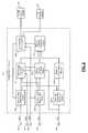
- FIG. 2is a functional block diagram of an example control system according to the principles of the present disclosure
- FIG. 3is a flowchart illustrating an example control method according to the principles of the present disclosure.
- FIGS. 4 and 5are graphs illustrating signals indicating operating conditions in a passive selective catalytic reduction (SCR) system according to the principles of the present disclosure.
- the temperature of a selective catalytic reduction (SCR) catalystaffects the efficiency of reactions within the SCR catalyst that reduce nitrogen oxide and affects the ability of the SCR catalyst to store ammonia.
- SCRselective catalytic reduction
- SCR systemstypically include a three-way catalyst disposed downstream from an engine and an SCR catalyst disposed downstream from the three-way catalyst.
- the temperature of the SCR catalystis affected by the distance between the engine and the SCR catalyst.
- the distance between the engine and an SCR catalyst that is disposed immediately downstream from a three-way catalystmay be relatively short. Therefore, the temperature of the SCR catalyst may be too low to effectively reduce nitrogen oxide only when the engine is initially started.
- Some SCR systemsmay include two or more SCR catalysts disposed downstream from a three-way catalyst.
- the distance between the engine and an SCR catalyst that is disposed downstream from another SCR catalystmay be relatively long. Therefore, the temperature of the SCR catalyst may be too low to effectively reduce nitrogen oxide well after the engine is started.
- the efficiency of reactions within the SCR catalyst that reduce nitrogen oxidemay not reach a peak efficiency until the engine is operating at a high load such as those experienced when a vehicle is driven on a highway.
- a system and methodestimates a first amount of ammonia stored in a first SCR catalyst and a second amount of ammonia stored in a second SCR catalyst.
- the second SCR catalystis disposed downstream from the first SCR catalyst.
- the first and second amountsmay be estimated based on the temperature of exhaust gas flowing through the SCR catalysts.
- a multiplieris determined based on the temperature of the second SCR catalyst.
- An effective amount of ammonia stored in the SCR catalystsis estimated based on a sum of the first amount and a product of the multiplier and the second amount.
- the effective amountrepresents the amount of ammonia that is effectively reduces nitrogen oxide.
- the air/fuel ratio of an engineis controlled based on the effective amount of ammonia stored in the SCR catalysts.
- the air/fuel ratio of the enginemay be adjusted to a rich air/fuel ratio when the effective amount is less than a first quantity.
- the air/fuel ratio of the enginemay be adjusted to a lean air/fuel ratio when the effective amount is greater than a second quantity.
- the first and second quantitiesmay be predetermined.
- the second quantitymay be greater than or equal to the first quantity.
- Estimating the amount of ammonia stored in the SCR catalysts based on the temperature of exhaust gas flowing through the SCR catalystsaccounts for declines in the ability of the SCR catalysts to store ammonia at high temperatures.
- Estimating the effective amount of ammonia stored in the SCR catalysts using the multiplieraccounts for reductions in the reaction efficiency of the second SCR catalyst at low temperatures. If more than one SCR catalyst is disposed downstream from another SCR catalyst, a multiplier may be applied to the estimated amount of ammonia stored in each SCR catalyst that is disposed downstream from another SCR catalyst.
- an example implementation of an engine system 100includes an engine 102 that combusts an air/fuel mixture to produce drive torque for a vehicle based on driver input from a driver input module 104 .
- Airis drawn into the engine 102 through an intake system 106 .
- the intake system 106may include an intake manifold 108 and a throttle valve 110 .
- the throttle valve 110may include a butterfly valve having a rotatable blade.
- An engine control module (ECM) 112controls a throttle actuator module 116 , which regulates opening of the throttle valve 110 to control the amount of air drawn into the intake manifold 108 .
- Air from the intake manifold 108is drawn into cylinders of the engine 102 .
- the engine 102may include multiple cylinders, for illustration purposes a single representative cylinder 114 is shown.
- the engine 102may include 2, 3, 4, 5, 6, 8, 10, and/or 12 cylinders.
- the ECM 112may deactivate some of the cylinders, which may improve fuel economy under certain engine operating conditions.
- the engine 102may operate using a four-stroke cycle.
- the four strokesdescribed below, are named the intake stroke, the compression stroke, the combustion stroke, and the exhaust stroke.
- the intake strokeis named the intake stroke, the compression stroke, the combustion stroke, and the exhaust stroke.
- two of the four strokesoccur within the cylinder 114 . Therefore, two crankshaft revolutions are necessary for the cylinder 114 to experience all four of the strokes.
- the ECM 112controls a fuel actuator module 120 , which regulates fuel injection to achieve a desired air/fuel ratio.
- Fuelmay be injected into the intake manifold 108 at a central location or at multiple locations, such as near the intake valve 118 of each of the cylinders. In various implementations (not shown), fuel may be injected directly into the cylinders or into mixing chambers associated with the cylinders.
- the fuel actuator module 120may halt injection of fuel to cylinders that are deactivated.
- the injected fuelmixes with air and creates an air/fuel mixture in the cylinder 114 .
- a piston(not shown) within the cylinder 114 compresses the air/fuel mixture.
- the engine 102may be a compression-ignition engine, in which case compression in the cylinder 114 ignites the air/fuel mixture.
- the engine 102may be a spark-ignition engine, in which case a spark actuator module 122 energizes a spark plug 124 in the cylinder 114 based on a signal from the ECM 112 , which ignites the air/fuel mixture.
- the timing of the sparkmay be specified relative to the time when the piston is at its topmost position, referred to as top dead center (TDC).
- the spark actuator module 122may be controlled by a timing signal specifying how far before or after TDC to generate the spark. Because piston position is directly related to crankshaft rotation, operation of the spark actuator module 122 may be synchronized with crankshaft angle. In various implementations, the spark actuator module 122 may halt provision of spark to deactivated cylinders.
- Generating the sparkmay be referred to as a firing event.
- the spark actuator module 122may have the ability to vary the timing of the spark for each firing event.
- the spark actuator module 122may even be capable of varying the spark timing for a next firing event when the spark timing signal is changed between a last firing event and the next firing event.
- the combustion strokeDuring the combustion stroke, the combustion of the air/fuel mixture drives the piston down, thereby driving the crankshaft.
- the combustion strokemay be defined as the time between the piston reaching TDC and the time at which the piston returns to bottom dead center (BDC).
- the pistonDuring the exhaust stroke, the piston begins moving up from BDC and expels the byproducts of combustion through an exhaust valve 126 .
- the byproducts of combustionare exhausted from the vehicle via an exhaust system 128 .
- the exhaust system 128includes a three-way catalyst (TWC) 130 and selective catalytic reduction (SCR) catalysts 132 , 134 .
- TWCthree-way catalyst
- SCRselective catalytic reduction
- the TWC 130reduces hydrocarbon, carbon monoxide, and nitrogen oxide and produces ammonia
- the SCR catalysts 132 , 134store the ammonia.
- the TWC 130reduces hydrocarbon and carbon monoxide, and the ammonia stored in the SCR catalysts 132 , 134 is used to reduce nitrogen oxide.
- the position of the crankshaftmay be measured using a crankshaft position (CKP) sensor 136 .
- the ECM 112may determine the speed of the crankshaft (i.e., the engine speed) based on the crankshaft position.
- the temperature of the engine coolantmay be measured using an engine coolant temperature (ECT) sensor 138 .
- the ECT sensor 138may be located within the engine 102 or at other locations where the coolant is circulated, such as a radiator (not shown).
- the pressure within the intake manifold 108may be measured using a manifold absolute pressure (MAP) sensor 140 .
- MAPmanifold absolute pressure
- engine vacuumwhich is the difference between ambient air pressure and the pressure within the intake manifold 108
- the mass flow rate of air flowing into the intake manifold 108may be measured using a mass air flow (MAF) sensor 142 .
- MAF sensor 142may be located in a housing that also includes the throttle valve 110 .
- the throttle actuator module 116may monitor the position of the throttle valve 110 using one or more throttle position sensors (TPS) 144 .
- TPSthrottle position sensors
- IATintake air temperature
- An air/fuel ratio of exhaust gas from the engine 102may be measured using an air/fuel ratio (AFR) sensor 148 .
- Nitrogen oxide and ammonia levels in exhaust gas from the engine 102may be measured using a nitrogen oxide (NOx) sensor 150 .
- the AFR sensor 148 and the NOx sensor 150may be positioned at or near the outlet of the TWC 130 .
- the temperature of exhaust gas from the engine 102may be measured using exhaust gas temperature (EGT) sensors 152 , 154 .
- the EGT sensor 152may be disposed at or near the inlet of the SCR catalyst 132 .
- the EGT sensor 154may be disposed at or near the inlet of the SCR catalyst 134 .
- the ECM 112may use signals from the sensors to make control decisions for the engine system 100 .
- the ECM 112estimates a first amount of ammonia stored in the SCR catalyst 132 and a second amount of ammonia stored in the SCR catalyst 134 .
- the ECM 112may estimate the first amount, the second amount, and a temperature of a substrate disposed in the SCR catalyst 134 based on input from the EGT sensors 152 , 154 .
- the ECM 112may determine a multiplier based on the substrate temperature and estimate an effective amount of ammonia stored in the SCR catalysts 132 , 134 based on a sum of the first amount and a product of the multiplier and the second amount.
- the ECM 112controls the air/fuel ratio of the engine 102 based on the effective amount of ammonia stored in the SCR catalysts 132 , 134 .
- the ECM 112may adjust the air/fuel ratio of the engine 102 to a rich air/fuel ratio when the effective amount is less than a first quantity.
- the ECM 112may adjust the air/fuel ratio of the engine 102 to a lean air/fuel ratio when the effective amount is greater than a second quantity.
- the first quantity and the second quantitymay be predetermined, and the second quantity may be greater than or equal to the first quantity.
- an example implementation of the ECM 112includes an exhaust flow determination module 202 , an emission level determination module 204 , and a substrate temperature estimation module 206 .
- the exhaust flow determination module 202determines a mass flow rate of exhaust gas from the engine 102 based on a mass flow rate of air entering the engine 102 and a fueling rate of the engine 102 .
- the exhaust flow determination module 202may receive the mass flow rate of air from the MAF sensor 142 .
- the exhaust flow determination module 202may receive the fueling rate from an air/fuel ratio control module 208 .
- the exhaust flow determination module 202outputs the mass flow rate of exhaust gas.
- the emission level determination module 204determines emission levels in exhaust gas at the outlet of the TWC 130 .
- the emission level determination module 204may set the ammonia level to zero and determine the nitrogen oxide level based on input from the NOx sensor 150 .
- the emission level determination module 204may set the nitrogen oxide level to zero and determine the ammonia level based on input from the NOx sensor 150 .
- the emission level determination module 204may determine the air/fuel ratio of the engine 102 based on input from the AFR sensor 148 .
- the emission level determination module 204outputs the emission levels.
- the substrate temperature estimation module 206estimates the temperature of the substrate disposed in the SCR catalyst 134 .
- the substrate temperature estimation module 206may estimate the substrate temperature based on the temperature of exhaust gas entering the SCR catalyst 134 and the mass flow rate of exhaust gas flowing through the SCR catalyst 134 .
- the substrate temperature estimation module 206may receive the exhaust gas temperature and mass flow rate from the EGT sensor 154 and the exhaust flow determination module 202 , respectively.
- the substrate temperature estimation module 206outputs the substrate temperature.
- a first storage estimation module 210estimates a first amount of ammonia stored in the SCR catalyst 132 .
- the first storage estimation module 210may estimate the first amount based on the temperature of exhaust gas entering the SCR catalyst 132 , the mass flow rate of exhaust gas flowing through the SCR catalyst 132 , and an air/fuel ratio of the engine 102 .
- the first storage estimation module 210may receive the exhaust gas temperature, the mass flow rate of exhaust gas, and the air/fuel ratio from the EGT sensor 152 , the exhaust flow determination module 202 , and the AFR sensor 148 , respectively.
- the first storage estimation module 210may also estimate the first amount based on nitrogen oxide and ammonia levels in exhaust gas at the outlet of the TWC 130 .
- the first storage estimation module 210may receive the nitrogen oxide and ammonia levels from the emission level determination module 204 .
- the first storage estimation module 210outputs the first amount.
- the first storage estimation module 210may estimate and output the nitrogen oxide and ammonia levels in exhaust gas exiting the SCR catalyst 132 .
- a second storage estimation module 212estimates a second amount of ammonia stored in the SCR catalyst 134 .
- the second storage estimation module 212may estimate the second amount based on the temperature of exhaust gas entering the SCR catalyst 134 , the mass flow rate of exhaust gas flowing through the SCR catalyst 134 , and an air/fuel ratio of the engine 102 .
- the second storage estimation module 212may receive the exhaust gas temperature, the mass flow rate of exhaust gas, and the air/fuel ratio from the EGT sensor 154 , the exhaust flow determination module 202 , and the AFR sensor 148 , respectively.
- the second storage estimation module 212may also estimate the second amount based on nitrogen oxide and ammonia levels in exhaust gas exiting the SCR catalyst 132 .
- the second storage estimation module 212may receive the nitrogen oxide and ammonia levels from the first storage estimation module 210 .
- the second storage estimation module 212outputs the second amount.
- a multiplier determination module 214determines a multiplier based on the substrate temperature.
- the multiplier determination module 214may set the multiplier equal to zero when the substrate temperature is less than a first temperature (e.g., 150° C.).
- the multiplier determination module 214may set the multiplier equal to one when the substrate temperature is greater than a second temperature (e.g., a temperature between 200° C. and 250° C., inclusive).
- the first temperature and the second temperaturemay be predetermined.
- the multiplier determination module 214may adjust the multiplier in a linear or nonlinear manner as the substrate temperature transitions between the first temperature and the second temperature.
- An effective storage estimation module 216estimates an effective amount of ammonia stored in the SCR catalysts 132 , 134 based on the first amount, the second amount, and the multiplier.
- the effective amountrepresents the amount of ammonia stored in the SCR catalysts 132 , 134 that effectively reduces nitrogen oxide.
- the effective storage estimation module 216may set the effective amount equal to a sum of the first amount and a product of the multiplier and the second amount.
- the effective storage estimation module 216outputs the effective amount
- the air/fuel ratio control module 208controls the air/fuel ratio based on the effective amount of ammonia stored in the SCR catalysts 132 , 134 .
- the air/fuel ratio control module 208may adjust the air/fuel ratio to a rich air/fuel ratio when the effective amount is less than a first quantity.
- the air/fuel ratio control module 208may adjust the air/fuel ratio to a lean air/fuel ratio when the effective amount is greater than a second quantity.
- the first quantity and the second quantitymay be predetermined, and the second quantity may be greater than or equal to the first quantity.
- the air/fuel ratio control module 208may control the air/fuel ratio based on other engine operating conditions such as engine speed, engine torque, air/fuel ratio, and SCR catalyst temperature.
- the air/fuel ratio control module 208may determine the engine speed based on input from the CKP sensor 136 .
- the air/fuel ratio control module 208may estimate the temperature of the SCR catalysts 132 , 134 based on input from the EGT sensors 152 , 154 , respectively, and the mass flow rate of exhaust gas.
- the air/fuel ratio control module 208controls the air/fuel ratio of the engine 102 by outputting signals to the throttle actuator module 116 and the fuel actuator module 120 indicating a desired throttle area and a desired fueling rate, respectively.
- a method for controlling an engine based on ammonia storage in multiple SCR catalystsbegins at 302 .
- the methoddetermines a mass flow rate of exhaust gas from the engine.
- the methodmay determine the mass flow rate of exhaust gas based on a sum of a mass flow rate of air entering the engine and a fueling rate of the engine.
- the methoddetermines nitrogen oxide and ammonia levels in exhaust gas.
- the methodmay set the ammonia level to zero and determine the nitrogen oxide level based on input from a NOx sensor.
- the methodmay set the nitrogen oxide level to zero and determine the ammonia level based on input from the NOx sensor. The air/fuel ratio of the engine may be measured.
- the methodestimates a first amount of ammonia stored in a first SCR catalyst.
- the first SCR catalystmay be disposed downstream from a three-way catalyst.
- the methodmay estimate the first amount based on the mass flow rate of exhaust gas, the air/fuel ratio of the engine, the nitrogen oxide and ammonia levels, and the temperature of exhaust gas entering the first SCR catalyst.
- the temperature of exhaust gas entering the first SCR catalystmay be measured or estimated.
- the methodestimates a second amount of ammonia stored in a second SCR catalyst that is disposed downstream from the first SCR catalyst.
- the methodmay estimate the second amount based on the mass flow rate of exhaust gas, the air/fuel ratio of the engine, the nitrogen oxide and ammonia levels, and the temperature of exhaust gas entering the second SCR catalyst.
- the temperature of exhaust gas entering the second SCR catalystmay be measured or estimated.
- the methodestimates the temperature of a substrate disposed in the second SCR catalyst.
- the methodmay estimate the substrate temperature based on the temperature of exhaust gas entering the second SCR catalyst and the mass flow rate of exhaust gas.
- the methodmay increase the rate at which the substrate temperature is adjusted in response to a change in the temperature of exhaust gas when the mass flow rate of exhaust gas increases.
- the methoddetermines a multiplier based on the substrate temperature.
- the methodmay set the multiplier equal to zero when the substrate temperature is less than a first temperature (e.g., 150° C.).
- the methodmay set the multiplier equal to one when the substrate temperature is greater than a second temperature (e.g., 200° C.).
- the first and second temperaturesmay be predetermined.
- the methodmay adjust the multiplier in a linear or nonlinear manner as the substrate temperature transitions between the first temperature and the second temperature.
- the methodestimates an effective amount of ammonia stored in the first catalyst and the second catalyst.
- the effective amountrepresents the amount of ammonia stored in the first and second SCR catalysts that effectively reduces nitrogen oxide.
- the methodmay determine a product of the multiplier and the second amount, and then set the effective amount equal to a sum of the first amount and the product.
- the methoddetermines whether the effective amount is greater than a predetermined amount. If the effective amount is greater than a predetermined amount, the method continues to 320 and sets the air/fuel ratio of the engine to a lean air/fuel ratio. Otherwise, the method continues at 322 and sets the air/fuel ratio of the engine to a rich air/fuel ratio.
- the AFR signal 402indicates an air/fuel ratio at the outlet of a three-way catalyst disposed in an exhaust system of an engine.
- the first NOx signal 404indicates a first NOx level at the outlet of a first SCR catalyst disposed downstream from the three-way catalyst.
- the second NOx signal 406indicates a second NOx level downstream from a second SCR catalyst in a tailpipe of the exhaust system.
- the second SCR catalystis disposed downstream from the first SCR catalyst.
- the first NOx signal 404 and the second NOx signal 406are plotted with respect to an x-axis 408 and a first y-axis 410 .
- the x-axis 408indicates time in seconds.
- the first y-axis 410represents emissions levels in parts per million (ppm).
- the AFR signal 402is plotted with respect to the x-axis 408 and a second y-axis 412 .
- the AFR signal 402continuously cycles between a lean air/fuel ratio and a rich air/fuel ratio.
- the AFR signal 402is stoichiometric when the AFR signal 402 is approximately equal to 14.7, the AFR signal 402 is rich when the AFR signal 402 is less than 14.7, and the AFR signal 402 is lean when the AFR signal 402 is greater than 14.7.
- the AFR signal 402is rich for approximately one-third of the illustrated period, and the AFR signal 402 is lean for approximately two-thirds of the illustrated period.
- the difference between the first NOx signal 404 and the second NOx signal 406indicates the amount of nitrogen oxide reduced in the second SCR catalyst. This difference is approximately zero when the AFR signal 402 is rich, as the amount of nitrogen oxide at the outlet of the three-way catalyst is approximately zero when the AFR signal 402 is rich.
- the first SCR catalyst and the second SCR catalystachieve a NOx reduction efficiency of approximately 80 percent when the AFR signal 402 is lean.
- the NOx sensor signal 502indicates nitrogen oxide and ammonia levels at the outlet of a three-way catalyst disposed in an exhaust system of an engine.
- the ammonia storage signal 504indicates an estimated amount of ammonia stored in a first SCR catalyst and a second SCR catalyst.
- the first SCR catalystis disposed downstream from the three-way catalyst.
- the second SCR catalystis disposed downstream from the first SCR catalyst.
- the NOx sensor signal 502is plotted with respect to an x-axis 506 and a first y-axis 508 .
- the x-axis 506indicates time in seconds.
- the first y-axis 508represents emissions levels in parts per million (ppm).
- the ammonia storage signal 504is plotted with respect to the x-axis 506 and a second y-axis 510 .
- the second y-axis 510represents ammonia storage in moles.
- the NOx sensor signal 502indicates nitrogen oxide levels when the air/fuel ratio of the engine is lean, and the NOx sensor signal indicates ammonia levels when the air/fuel ratio is rich or stoichiometric.
- the amount of ammonia produced in the three-way catalyst when the air/fuel ratio is rich or stoichiometricis greater than the amount of nitrogen oxide produced by the engine when the air/fuel ratio is lean.
- the NOx sensor signal 502increases when the air/fuel ratio is switched from lean to rich.
- the air/fuel ratio of the engineis switched between rich and lean to maintain the ammonia storage signal 504 within a desired range.
- the air/fuel ratio of the engineis adjusted to rich when the ammonia storage signal 504 is less than approximately 0.005 moles.
- the air/fuel ratio of the engineis adjusted to lean when the ammonia storage signal 504 is greater than approximately 0.007 moles.
- modulemay refer to, be part of, or include an Application Specific Integrated Circuit (ASIC); an electronic circuit; a combinational logic circuit; a field programmable gate array (FPGA); a processor (shared, dedicated, or group) that executes code; other suitable hardware components that provide the described functionality; or a combination of some or all of the above, such as in a system-on-chip.
- ASICApplication Specific Integrated Circuit
- FPGAfield programmable gate array
- the term modulemay include memory (shared, dedicated, or group) that stores code executed by the processor.
- codemay include software, firmware, and/or microcode, and may refer to programs, routines, functions, classes, and/or objects.
- sharedmeans that some or all code from multiple modules may be executed using a single (shared) processor. In addition, some or all code from multiple modules may be stored by a single (shared) memory.
- groupmeans that some or all code from a single module may be executed using a group of processors. In addition, some or all code from a single module may be stored using a group of memories.
- the apparatuses and methods described hereinmay be implemented by one or more computer programs executed by one or more processors.
- the computer programsinclude processor-executable instructions that are stored on a non-transitory tangible computer readable medium.
- the computer programsmay also include stored data.
- Non-limiting examples of the non-transitory tangible computer readable mediumare nonvolatile memory, magnetic storage, and optical storage.
Landscapes
- Engineering & Computer Science (AREA)
- Chemical & Material Sciences (AREA)
- Combustion & Propulsion (AREA)
- Mechanical Engineering (AREA)
- General Engineering & Computer Science (AREA)
- Chemical Kinetics & Catalysis (AREA)
- Health & Medical Sciences (AREA)
- Toxicology (AREA)
- Exhaust Gas After Treatment (AREA)
- Electrical Control Of Air Or Fuel Supplied To Internal-Combustion Engine (AREA)
- Exhaust Gas Treatment By Means Of Catalyst (AREA)
Abstract
Description
Claims (20)
Priority Applications (3)
| Application Number | Priority Date | Filing Date | Title |
|---|---|---|---|
| US13/471,861US9188071B2 (en) | 2012-05-15 | 2012-05-15 | System and method for controlling an engine based on ammonia storage in multiple selective catalytic reduction catalysts |
| DE102013208361.0ADE102013208361B4 (en) | 2012-05-15 | 2013-05-07 | Method for controlling an engine based on ammonia storage in several catalysts for selective catalytic reduction |
| CN201310179140.5ACN103422958B (en) | 2012-05-15 | 2013-05-15 | The system and method for electromotor is controlled based on the ammonia memory state in catalyst converter |
Applications Claiming Priority (1)
| Application Number | Priority Date | Filing Date | Title |
|---|---|---|---|
| US13/471,861US9188071B2 (en) | 2012-05-15 | 2012-05-15 | System and method for controlling an engine based on ammonia storage in multiple selective catalytic reduction catalysts |
Publications (2)
| Publication Number | Publication Date |
|---|---|
| US20130311065A1 US20130311065A1 (en) | 2013-11-21 |
| US9188071B2true US9188071B2 (en) | 2015-11-17 |
Family
ID=49511116
Family Applications (1)
| Application Number | Title | Priority Date | Filing Date |
|---|---|---|---|
| US13/471,861Active2034-07-29US9188071B2 (en) | 2012-05-15 | 2012-05-15 | System and method for controlling an engine based on ammonia storage in multiple selective catalytic reduction catalysts |
Country Status (3)
| Country | Link |
|---|---|
| US (1) | US9188071B2 (en) |
| CN (1) | CN103422958B (en) |
| DE (1) | DE102013208361B4 (en) |
Cited By (1)
| Publication number | Priority date | Publication date | Assignee | Title |
|---|---|---|---|---|
| US20190162096A1 (en)* | 2016-07-29 | 2019-05-30 | Cummins Inc. | Methods and systems for removing deposits in an aftertreatment system |
Families Citing this family (20)
| Publication number | Priority date | Publication date | Assignee | Title |
|---|---|---|---|---|
| US8919099B2 (en)* | 2011-06-10 | 2014-12-30 | GM Global Technology Operations LLC | System and method for determining an ammonia generation rate in a three-way catalyst |
| US9714625B2 (en) | 2011-07-28 | 2017-07-25 | GM Global Technology Operations LLC | System and method for controlling ammonia levels in a selective catalytic reduction catalyst using a nitrogen oxide sensor |
| US9188071B2 (en) | 2012-05-15 | 2015-11-17 | GM Global Technology Operations LLC | System and method for controlling an engine based on ammonia storage in multiple selective catalytic reduction catalysts |
| US9016244B2 (en)* | 2013-04-23 | 2015-04-28 | Ford Global Technologies, Llc | Engine control for catalyst regeneration |
| US9309797B2 (en)* | 2014-03-05 | 2016-04-12 | GM Global Technology Operations LLC | System and method for controlling dosing in selective catalytic reduction catalyst |
| US9605579B2 (en)* | 2014-12-12 | 2017-03-28 | General Electric Company | Systems and methods for model based control of catalytic converter systems |
| JP6102907B2 (en) | 2014-12-26 | 2017-03-29 | トヨタ自動車株式会社 | Exhaust purification device deterioration diagnosis device |
| DE102016201602A1 (en)* | 2016-02-03 | 2017-08-03 | Robert Bosch Gmbh | Method for determining an ammonia mass flow |
| US20180008932A1 (en)* | 2016-07-11 | 2018-01-11 | GM Global Technology Operations LLC | Def dosing for selective catalytic reduction catalysts |
| GB2584253B (en)* | 2018-02-15 | 2022-08-03 | Cummins Emission Solutions Inc | Systems and methods for determining exhaust flow rate |
| JP2020084930A (en)* | 2018-11-29 | 2020-06-04 | いすゞ自動車株式会社 | Exhaust emission control device and vehicle |
| US11976582B2 (en) | 2020-07-21 | 2024-05-07 | Paccar Inc | Methods for diagnostics and operation of an emissions aftertreatment system |
| US11352927B2 (en) | 2020-07-21 | 2022-06-07 | Paccar Inc | Control of selective catalytic reduction in heavy-duty motor vehicle engines |
| US11181026B1 (en) | 2020-07-21 | 2021-11-23 | Paccar Inc | Methods for operation of an emissions aftertreatment system for NOx control during regeneration of diesel particulate filter |
| US11499463B2 (en) | 2020-07-21 | 2022-11-15 | Paccar Inc | Methods for evaluating diesel exhaust fluid quality |
| US11879367B2 (en) | 2020-07-21 | 2024-01-23 | Paccar Inc | NOx sensor diagnostics in heavy-duty motor vehicle engines |
| US11725560B2 (en) | 2020-07-21 | 2023-08-15 | Paccar Inc | Heater control in heavy-duty motor vehicle engines |
| US11428136B2 (en) | 2020-07-21 | 2022-08-30 | Paccar Inc | Heater diagnostics in heavy-duty motor vehicle engines |
| US11326493B2 (en)* | 2020-07-21 | 2022-05-10 | Paccar Inc | Ammonia storage capacity of SCR catalyst unit |
| CN119616698A (en)* | 2024-11-20 | 2025-03-14 | 一汽解放汽车有限公司 | Post-treatment temperature control method and system and vehicle |
Citations (41)
| Publication number | Priority date | Publication date | Assignee | Title |
|---|---|---|---|---|
| US5021227A (en) | 1989-02-02 | 1991-06-04 | Nippon Shokubai Kagaku Kogyo Co., Ltd. | Method of removing nitrogen oxides in exhaust gases from a diesel engine |
| US5746052A (en) | 1994-09-13 | 1998-05-05 | Toyota Jidosha Kabushiki Kaisha | Exhaust gas purification device for an engine |
| US5778667A (en) | 1996-06-18 | 1998-07-14 | Toyota Jidosha Kabushiki, Kaisha | Method and a device for purifying combustion exhaust gas |
| US5782087A (en) | 1995-11-10 | 1998-07-21 | Toyota Jidosha Kabushiki Kaisha | Device for purifying exhaust gas of an engine |
| US6109024A (en) | 1997-05-12 | 2000-08-29 | Toyota Jidosha Kabushiki Kaisha | Exhaust gas purification device for an internal combustion engine |
| US6119452A (en) | 1995-11-17 | 2000-09-19 | Toyota Jidosha Kabushiki Kaisha | Device for purifying exhaust gas of internal combustion engine |
| EP1061244A2 (en) | 1999-06-14 | 2000-12-20 | Honda Giken Kogyo Kabushiki Kaisha | Exhaust gas purifying apparatus for internal combustion engine |
| DE10041891A1 (en) | 1999-10-11 | 2001-04-19 | Daimler Chrysler Ag | Purification device has devices for determining reductant amount intermediately stored in reductant storage and nitrogen oxide reducing catalyst |
| US6345496B1 (en) | 1995-11-09 | 2002-02-12 | Toyota Jidosha Kabushiki Kaisha | Method and device for purifying exhaust gas of an engine |
| US20020069640A1 (en) | 2000-12-08 | 2002-06-13 | Toyota Jidosha Kabushiki Kaisha | Emission control apparatus of internal combustion engine |
| US6662552B1 (en) | 1999-05-19 | 2003-12-16 | Daimlerchrysler Ag | Exhaust-gas cleaning system and method with internal ammonia generation, for the reduction of nitrogen oxides |
| US6775623B2 (en) | 2002-10-11 | 2004-08-10 | General Motors Corporation | Real-time nitrogen oxides (NOx) estimation process |
| US20070033928A1 (en) | 2004-07-14 | 2007-02-15 | Eaton Corporation | Hybrid catalyst system for exhaust emissions reduction |
| US7210288B2 (en) | 2003-01-02 | 2007-05-01 | Daimlerchrysler Ag | Exhaust gas aftertreatment installation and method |
| US20070137182A1 (en) | 2005-12-21 | 2007-06-21 | Driscoll James J | Selective catalytic reduction system |
| US20070271908A1 (en) | 2006-05-25 | 2007-11-29 | Hemingway Mark D | Engine exhaust emission control system providing on-board ammonia generation |
| US20090165442A1 (en) | 2005-12-08 | 2009-07-02 | Isuzu Motors Limited Of Tokyo | Method for Controlling Exhaust Gas Purification System |
| US20090199543A1 (en) | 2006-08-30 | 2009-08-13 | Toyota Jidosha Kabushiki Kaisha | Catalyst monitoring system and monitoring method |
| US7628009B2 (en) | 2005-10-07 | 2009-12-08 | Eaton Corporation | Exhaust aftertreatment system with transmission control |
| US20100043402A1 (en) | 2008-05-02 | 2010-02-25 | Gm Global Technology Operations, Inc. | PASSIVE AMMONIA-SELECTIVE CATALYTIC REDUCTION FOR NOx CONTROL IN INTERNAL COMBUSTION ENGINES |
| US20100057328A1 (en) | 2008-08-29 | 2010-03-04 | Gm Global Technology Operations, Inc. | Lean nitrogen oxide emission control system and method |
| US7673444B2 (en) | 2004-10-29 | 2010-03-09 | Nissan Diesel Motor Co., Ltd. | Exhaust gas purification apparatus |
| US20100071347A1 (en) | 2007-09-05 | 2010-03-25 | Toyota Jidosha Kabushiki Kaisha | Exhaust purification device of an internal combustion engine |
| US20100107605A1 (en) | 2008-05-02 | 2010-05-06 | Gm Global Technology Operations, Inc. | PASSIVE AMMONIA-SELECTIVE CATALYTIC REDUCTION FOR NOx CONTROL IN INTERNAL COMBUSTION ENGINES |
| US20100111794A1 (en)* | 2007-06-08 | 2010-05-06 | Toyota Jidosha Kabushiki Kaisha | Internal combustion engine exhaust gas purification apparatus and method for controlling same |
| US20100107606A1 (en)* | 2008-05-02 | 2010-05-06 | Gm Global Technology Operations, Inc. | PASSIVE AMMONIA-SELECTIVE CATALYTIC REDUCTION FOR NOx CONTROL IN INTERNAL COMBUSTION ENGINES |
| US20100192545A1 (en)* | 2009-01-30 | 2010-08-05 | Gm Global Technology Operations, Inc. | Exhaust aftertreatment system |
| US20100326052A1 (en) | 2009-06-29 | 2010-12-30 | Gm Global Technology Operations, Inc. | Method for monitoring ammonia storage in an exhaust aftertreatment system |
| US20110041480A1 (en)* | 2008-04-18 | 2011-02-24 | Honda Motor Co., Ltd. | Exhaust purification apparatus for internal combustion engine |
| US8005605B2 (en) | 2008-10-14 | 2011-08-23 | Honda Motor Co., Ltd. | Control system and method for internal combustion engine and engine control unit |
| US20120102927A1 (en)* | 2009-06-03 | 2012-05-03 | Toyota Jidosha Kabushiki Kaisha | Exhaust purification system of internal combustion engine |
| US20120117954A1 (en)* | 2010-01-25 | 2012-05-17 | Honda Motor Co., Ltd. | Exhaust purification system for internal combustion engine |
| US20120167553A1 (en) | 2010-12-29 | 2012-07-05 | GM Global Technology Operations LLC | Exhaust aftertreatment systems that include an ammonia-scr catalyst promoted with an oxygen storage material |
| US20120180558A1 (en) | 2011-01-19 | 2012-07-19 | GM Global Technology Operations LLC | Method for monitoring exhaust gas aftertreatment devices |
| US20120222406A1 (en) | 2009-11-18 | 2012-09-06 | Toyota Jidosha Kabushiki Kaisha | Exhaust purification system for internal combustion engine |
| US20120316754A1 (en) | 2011-06-09 | 2012-12-13 | GM Global Technology Operations LLC | Method for operating a spark-ignition, direct-injection internal combustion engine |
| US20120311998A1 (en) | 2011-06-10 | 2012-12-13 | GM Global Technology Operations LLC | System and method for determining an ammonia generation rate in a three-way catalyst |
| US20130025261A1 (en) | 2011-07-28 | 2013-01-31 | GM Global Technology Operations LLC | System and method for controlling ammonia levels in a selective catalytic reduction catalyst using a nitrogen oxide sensor |
| US20130095002A1 (en) | 2011-10-13 | 2013-04-18 | Kia Motors Corporation | Exhaust gas purifying filter, system of regenerating gasoline particulate filter, and method thereof |
| US20130311065A1 (en) | 2012-05-15 | 2013-11-21 | GM Global Technology Operations LLC | System and method for controlling an engine based on ammonia storage in multiple selective catalytic reduction catalysts |
| US20140013725A1 (en) | 2012-07-10 | 2014-01-16 | GM Global Technology Operations LLC | Kinetics-based scr control model improvement |
Family Cites Families (4)
| Publication number | Priority date | Publication date | Assignee | Title |
|---|---|---|---|---|
| DE3379C (en) | Graf VON PFEIL, Königl. Landrath, in Hausdorf (Kreis-Neurode) | Double clapboard for roofing | ||
| US7485272B2 (en)* | 2005-11-30 | 2009-02-03 | Caterpillar Inc. | Multi-stage system for selective catalytic reduction |
| US8516798B2 (en) | 2009-07-30 | 2013-08-27 | Ford Global Technologies, Llc | Methods and systems for control of an emission system with more than one SCR region |
| JP4989738B2 (en)* | 2010-02-09 | 2012-08-01 | 本田技研工業株式会社 | Exhaust gas purification device for internal combustion engine |
- 2012
- 2012-05-15USUS13/471,861patent/US9188071B2/enactiveActive
- 2013
- 2013-05-07DEDE102013208361.0Apatent/DE102013208361B4/enactiveActive
- 2013-05-15CNCN201310179140.5Apatent/CN103422958B/enactiveActive
Patent Citations (47)
| Publication number | Priority date | Publication date | Assignee | Title |
|---|---|---|---|---|
| US5021227A (en) | 1989-02-02 | 1991-06-04 | Nippon Shokubai Kagaku Kogyo Co., Ltd. | Method of removing nitrogen oxides in exhaust gases from a diesel engine |
| US5746052A (en) | 1994-09-13 | 1998-05-05 | Toyota Jidosha Kabushiki Kaisha | Exhaust gas purification device for an engine |
| US6345496B1 (en) | 1995-11-09 | 2002-02-12 | Toyota Jidosha Kabushiki Kaisha | Method and device for purifying exhaust gas of an engine |
| US5782087A (en) | 1995-11-10 | 1998-07-21 | Toyota Jidosha Kabushiki Kaisha | Device for purifying exhaust gas of an engine |
| US6119452A (en) | 1995-11-17 | 2000-09-19 | Toyota Jidosha Kabushiki Kaisha | Device for purifying exhaust gas of internal combustion engine |
| US5778667A (en) | 1996-06-18 | 1998-07-14 | Toyota Jidosha Kabushiki, Kaisha | Method and a device for purifying combustion exhaust gas |
| US6109024A (en) | 1997-05-12 | 2000-08-29 | Toyota Jidosha Kabushiki Kaisha | Exhaust gas purification device for an internal combustion engine |
| US6662552B1 (en) | 1999-05-19 | 2003-12-16 | Daimlerchrysler Ag | Exhaust-gas cleaning system and method with internal ammonia generation, for the reduction of nitrogen oxides |
| EP1061244A2 (en) | 1999-06-14 | 2000-12-20 | Honda Giken Kogyo Kabushiki Kaisha | Exhaust gas purifying apparatus for internal combustion engine |
| DE10041891A1 (en) | 1999-10-11 | 2001-04-19 | Daimler Chrysler Ag | Purification device has devices for determining reductant amount intermediately stored in reductant storage and nitrogen oxide reducing catalyst |
| US20020069640A1 (en) | 2000-12-08 | 2002-06-13 | Toyota Jidosha Kabushiki Kaisha | Emission control apparatus of internal combustion engine |
| US6775623B2 (en) | 2002-10-11 | 2004-08-10 | General Motors Corporation | Real-time nitrogen oxides (NOx) estimation process |
| US7210288B2 (en) | 2003-01-02 | 2007-05-01 | Daimlerchrysler Ag | Exhaust gas aftertreatment installation and method |
| US20070175208A1 (en) | 2003-01-02 | 2007-08-02 | Daimlerchrysler Ag | Exhaust Gas Aftertreatment Installation and Method |
| US20070033928A1 (en) | 2004-07-14 | 2007-02-15 | Eaton Corporation | Hybrid catalyst system for exhaust emissions reduction |
| US7673444B2 (en) | 2004-10-29 | 2010-03-09 | Nissan Diesel Motor Co., Ltd. | Exhaust gas purification apparatus |
| US7628009B2 (en) | 2005-10-07 | 2009-12-08 | Eaton Corporation | Exhaust aftertreatment system with transmission control |
| US20090165442A1 (en) | 2005-12-08 | 2009-07-02 | Isuzu Motors Limited Of Tokyo | Method for Controlling Exhaust Gas Purification System |
| US20070137182A1 (en) | 2005-12-21 | 2007-06-21 | Driscoll James J | Selective catalytic reduction system |
| US7472545B2 (en) | 2006-05-25 | 2009-01-06 | Delphi Technologies, Inc. | Engine exhaust emission control system providing on-board ammonia generation |
| US20070271908A1 (en) | 2006-05-25 | 2007-11-29 | Hemingway Mark D | Engine exhaust emission control system providing on-board ammonia generation |
| US20090199543A1 (en) | 2006-08-30 | 2009-08-13 | Toyota Jidosha Kabushiki Kaisha | Catalyst monitoring system and monitoring method |
| US20100111794A1 (en)* | 2007-06-08 | 2010-05-06 | Toyota Jidosha Kabushiki Kaisha | Internal combustion engine exhaust gas purification apparatus and method for controlling same |
| US20100071347A1 (en) | 2007-09-05 | 2010-03-25 | Toyota Jidosha Kabushiki Kaisha | Exhaust purification device of an internal combustion engine |
| US20110041480A1 (en)* | 2008-04-18 | 2011-02-24 | Honda Motor Co., Ltd. | Exhaust purification apparatus for internal combustion engine |
| US20100043402A1 (en) | 2008-05-02 | 2010-02-25 | Gm Global Technology Operations, Inc. | PASSIVE AMMONIA-SELECTIVE CATALYTIC REDUCTION FOR NOx CONTROL IN INTERNAL COMBUSTION ENGINES |
| US20100107605A1 (en) | 2008-05-02 | 2010-05-06 | Gm Global Technology Operations, Inc. | PASSIVE AMMONIA-SELECTIVE CATALYTIC REDUCTION FOR NOx CONTROL IN INTERNAL COMBUSTION ENGINES |
| US20100107606A1 (en)* | 2008-05-02 | 2010-05-06 | Gm Global Technology Operations, Inc. | PASSIVE AMMONIA-SELECTIVE CATALYTIC REDUCTION FOR NOx CONTROL IN INTERNAL COMBUSTION ENGINES |
| US8393140B2 (en)* | 2008-05-02 | 2013-03-12 | GM Global Technology Operations LLC | Passive ammonia-selective catalytic reduction for NOx control in internal combustion engines |
| US20100057328A1 (en) | 2008-08-29 | 2010-03-04 | Gm Global Technology Operations, Inc. | Lean nitrogen oxide emission control system and method |
| US8041498B2 (en) | 2008-08-29 | 2011-10-18 | GM Global Technology Operations LLC | Lean nitrogen oxide emission control system and method |
| US8005605B2 (en) | 2008-10-14 | 2011-08-23 | Honda Motor Co., Ltd. | Control system and method for internal combustion engine and engine control unit |
| DE102009054046A1 (en) | 2008-11-24 | 2010-09-09 | GM Global Technology Operations, Inc., Detroit | Internal combustion engine i.e. lean-burn spark-ignition engine, operating method for vehicle, involves storing ammonia on ammonia-selective catalytic reduction device fluidly serially connected downstream of catalytic device |
| CN101929374A (en) | 2008-11-24 | 2010-12-29 | 通用汽车环球科技运作公司 | Passive ammonia-selective catalytic reduction for nox control in internal combustion engines |
| US20100192545A1 (en)* | 2009-01-30 | 2010-08-05 | Gm Global Technology Operations, Inc. | Exhaust aftertreatment system |
| US20120102927A1 (en)* | 2009-06-03 | 2012-05-03 | Toyota Jidosha Kabushiki Kaisha | Exhaust purification system of internal combustion engine |
| US20100326052A1 (en) | 2009-06-29 | 2010-12-30 | Gm Global Technology Operations, Inc. | Method for monitoring ammonia storage in an exhaust aftertreatment system |
| US20120222406A1 (en) | 2009-11-18 | 2012-09-06 | Toyota Jidosha Kabushiki Kaisha | Exhaust purification system for internal combustion engine |
| US20120117954A1 (en)* | 2010-01-25 | 2012-05-17 | Honda Motor Co., Ltd. | Exhaust purification system for internal combustion engine |
| US20120167553A1 (en) | 2010-12-29 | 2012-07-05 | GM Global Technology Operations LLC | Exhaust aftertreatment systems that include an ammonia-scr catalyst promoted with an oxygen storage material |
| US20120180558A1 (en) | 2011-01-19 | 2012-07-19 | GM Global Technology Operations LLC | Method for monitoring exhaust gas aftertreatment devices |
| US20120316754A1 (en) | 2011-06-09 | 2012-12-13 | GM Global Technology Operations LLC | Method for operating a spark-ignition, direct-injection internal combustion engine |
| US20120311998A1 (en) | 2011-06-10 | 2012-12-13 | GM Global Technology Operations LLC | System and method for determining an ammonia generation rate in a three-way catalyst |
| US20130025261A1 (en) | 2011-07-28 | 2013-01-31 | GM Global Technology Operations LLC | System and method for controlling ammonia levels in a selective catalytic reduction catalyst using a nitrogen oxide sensor |
| US20130095002A1 (en) | 2011-10-13 | 2013-04-18 | Kia Motors Corporation | Exhaust gas purifying filter, system of regenerating gasoline particulate filter, and method thereof |
| US20130311065A1 (en) | 2012-05-15 | 2013-11-21 | GM Global Technology Operations LLC | System and method for controlling an engine based on ammonia storage in multiple selective catalytic reduction catalysts |
| US20140013725A1 (en) | 2012-07-10 | 2014-01-16 | GM Global Technology Operations LLC | Kinetics-based scr control model improvement |
Non-Patent Citations (4)
| Title |
|---|
| David Garrod, Ph.D., Esq.; "Glossary of Judicial Claim Constructions in the Electronics, Computer and Business Method Arts"; p. 257; © 2010 ; 2 pages. |
| Office Action dated Oct. 18, 2013 from the German Patent Office for German Patent Application No. 10 2012 209 469.5; 7 pages. |
| U.S. Appl. No. 13/157,669, filed Jun. 10, 2011, Sun et al. |
| U.S. Appl. No. 13/192,859, filed Jul. 28, 2011, Sun et al. |
Cited By (3)
| Publication number | Priority date | Publication date | Assignee | Title |
|---|---|---|---|---|
| US20190162096A1 (en)* | 2016-07-29 | 2019-05-30 | Cummins Inc. | Methods and systems for removing deposits in an aftertreatment system |
| US10961889B2 (en)* | 2016-07-29 | 2021-03-30 | Cummins Inc. | Methods and systems for removing deposits in an aftertreatment system |
| US11591944B2 (en) | 2016-07-29 | 2023-02-28 | Cummins Inc. | Methods and systems for removing deposits in an aftertreatment system |
Also Published As
| Publication number | Publication date |
|---|---|
| CN103422958A (en) | 2013-12-04 |
| DE102013208361A1 (en) | 2013-11-21 |
| US20130311065A1 (en) | 2013-11-21 |
| CN103422958B (en) | 2016-08-17 |
| DE102013208361B4 (en) | 2020-07-30 |
Similar Documents
| Publication | Publication Date | Title |
|---|---|---|
| US9188071B2 (en) | System and method for controlling an engine based on ammonia storage in multiple selective catalytic reduction catalysts | |
| US9714625B2 (en) | System and method for controlling ammonia levels in a selective catalytic reduction catalyst using a nitrogen oxide sensor | |
| CN102691551B (en) | Correct being stored in NH in selective catalytic reduction system operating 3the method of estimation | |
| US8919099B2 (en) | System and method for determining an ammonia generation rate in a three-way catalyst | |
| CN103670754A (en) | System and method for controlling fuel injection in an engine based on piston temperature | |
| US20130268176A1 (en) | Exhaust gas recirculation control systems and methods for low engine delta pressure conditions | |
| US9175627B2 (en) | Fuel injection control apparatus for an internal combustion engine | |
| US9932917B2 (en) | Exhaust gas recirculation control systems and methods | |
| US8839605B2 (en) | Exhaust methane control systems and methods | |
| US10683822B2 (en) | Fuel-cetane-number estimation method and apparatus | |
| US8631645B2 (en) | Thermal management systems for efficient lean operating engines | |
| US9328690B2 (en) | System and method for controlling fuel injection timing to decrease emissions during transient engine operation | |
| US9771888B2 (en) | System and method for controlling an engine based on an oxygen storage capability of a catalytic converter | |
| US10450987B2 (en) | Method of operating a fuel injector | |
| US11415068B2 (en) | System and method for controlling engine operating parameters during engine warm-up to reduce emissions | |
| CN106437955B (en) | Method for operating a vehicle system | |
| CN102606327A (en) | System and method for controlling fuel injection to decrease particulate emissions during transient engine operation | |
| US9845746B2 (en) | Internal combustion engine provided with a selective catalytic reduction system | |
| US9869287B2 (en) | System and method for controlling fuel injection timing based on spark ignition timing while heating a catalyst to the light-off temperature | |
| GB2560758A (en) | A method of thermal protecting a particulate filter of an internal combustion engine | |
| GB2523317A (en) | A control apparatus for operating a fuel injector of an internal combustion engine | |
| CN110067662B (en) | Control method for cylinder balancing of internal combustion engine | |
| JP4910941B2 (en) | Control method and control apparatus for internal combustion engine | |
| GB2486197A (en) | A method of feed-forward control for an internal combustion engine | |
| JP2016050547A (en) | Exhaust purification system |
Legal Events
| Date | Code | Title | Description |
|---|---|---|---|
| AS | Assignment | Owner name:GM GLOBAL TECHNOLOGY OPERATIONS LLC, MICHIGAN Free format text:ASSIGNMENT OF ASSIGNORS INTEREST;ASSIGNORS:SUN, MIN;PERRY, KEVIN L.;REEL/FRAME:028746/0009 Effective date:20120427 | |
| AS | Assignment | Owner name:ENERGY, UNITED STATES DEPARTMENT OF, DISTRICT OF C Free format text:CONFIRMATORY LICENSE;ASSIGNOR:GENERAL MOTORS GLOBAL TECHNOLOGY OPERATIONS;REEL/FRAME:030407/0241 Effective date:20120711 | |
| AS | Assignment | Owner name:ENERGY, UNITED STATES DEPARTMENT OF, DISTRICT OF C Free format text:CONFIRMATORY LICENSE;ASSIGNOR:GENERAL MOTORS GLOBAL TECHNOLOGY OPERATIONS;REEL/FRAME:030605/0778 Effective date:20120711 | |
| AS | Assignment | Owner name:WILMINGTON TRUST COMPANY, DELAWARE Free format text:SECURITY AGREEMENT;ASSIGNOR:GM GLOBAL TECHNOLOGY OPERATIONS LLC;REEL/FRAME:030694/0500 Effective date:20101027 | |
| AS | Assignment | Owner name:GM GLOBAL TECHNOLOGY OPERATIONS LLC, MICHIGAN Free format text:RELEASE BY SECURED PARTY;ASSIGNOR:WILMINGTON TRUST COMPANY;REEL/FRAME:034287/0415 Effective date:20141017 | |
| STCF | Information on status: patent grant | Free format text:PATENTED CASE | |
| MAFP | Maintenance fee payment | Free format text:PAYMENT OF MAINTENANCE FEE, 4TH YEAR, LARGE ENTITY (ORIGINAL EVENT CODE: M1551); ENTITY STATUS OF PATENT OWNER: LARGE ENTITY Year of fee payment:4 | |
| MAFP | Maintenance fee payment | Free format text:PAYMENT OF MAINTENANCE FEE, 8TH YEAR, LARGE ENTITY (ORIGINAL EVENT CODE: M1552); ENTITY STATUS OF PATENT OWNER: LARGE ENTITY Year of fee payment:8 |