US9187959B2 - Automated steerable hole enlargement drilling device and methods - Google Patents
Automated steerable hole enlargement drilling device and methodsDownload PDFInfo
- Publication number
- US9187959B2 US9187959B2US11/681,370US68137007AUS9187959B2US 9187959 B2US9187959 B2US 9187959B2US 68137007 AUS68137007 AUS 68137007AUS 9187959 B2US9187959 B2US 9187959B2
- Authority
- US
- United States
- Prior art keywords
- hole enlargement
- steering device
- drill bit
- drilling
- enlargement device
- Prior art date
- Legal status (The legal status is an assumption and is not a legal conclusion. Google has not performed a legal analysis and makes no representation as to the accuracy of the status listed.)
- Active
Links
- 238000005553drillingMethods0.000titleclaimsabstractdescription93
- 238000000034methodMethods0.000titledescription8
- 238000005520cutting processMethods0.000claimsabstractdescription36
- 230000015572biosynthetic processEffects0.000claimsdescription32
- 239000012530fluidSubstances0.000claimsdescription30
- 230000006854communicationEffects0.000claimsdescription13
- 238000004891communicationMethods0.000claimsdescription13
- 239000004020conductorSubstances0.000claimsdescription12
- 238000011156evaluationMethods0.000claimsdescription9
- 230000004044responseEffects0.000claimsdescription7
- 230000008961swellingEffects0.000claimsdescription7
- 230000003287optical effectEffects0.000claimsdescription2
- 230000000149penetrating effectEffects0.000claims4
- 230000009849deactivationEffects0.000claims1
- 238000005755formation reactionMethods0.000description19
- 230000005540biological transmissionEffects0.000description4
- 230000007175bidirectional communicationEffects0.000description3
- 230000002457bidirectional effectEffects0.000description3
- 235000019282butylated hydroxyanisoleNutrition0.000description3
- 239000004568cementSubstances0.000description3
- 230000015654memoryEffects0.000description3
- 230000008569processEffects0.000description3
- 239000003381stabilizerSubstances0.000description3
- XLYOFNOQVPJJNP-UHFFFAOYSA-NwaterSubstancesOXLYOFNOQVPJJNP-UHFFFAOYSA-N0.000description3
- 230000009471actionEffects0.000description2
- 230000000712assemblyEffects0.000description2
- 238000000429assemblyMethods0.000description2
- 239000000463materialSubstances0.000description2
- 238000012986modificationMethods0.000description2
- 230000004048modificationEffects0.000description2
- 230000035699permeabilityEffects0.000description2
- 238000012545processingMethods0.000description2
- 230000000087stabilizing effectEffects0.000description2
- 238000005452bendingMethods0.000description1
- 230000008901benefitEffects0.000description1
- 238000004590computer programMethods0.000description1
- 238000012937correctionMethods0.000description1
- 238000006073displacement reactionMethods0.000description1
- 230000009977dual effectEffects0.000description1
- 230000000694effectsEffects0.000description1
- 239000000835fiberSubstances0.000description1
- 230000005251gamma rayEffects0.000description1
- 229930195733hydrocarbonNatural products0.000description1
- 150000002430hydrocarbonsChemical class0.000description1
- 238000011065in-situ storageMethods0.000description1
- 238000005461lubricationMethods0.000description1
- -1oil and gasChemical class0.000description1
- 230000002093peripheral effectEffects0.000description1
- 238000010248power generationMethods0.000description1
- 238000000518rheometryMethods0.000description1
- 239000011435rockSubstances0.000description1
- 230000035939shockEffects0.000description1
- 239000000126substanceSubstances0.000description1
- 238000012546transferMethods0.000description1
Images


Classifications
- E—FIXED CONSTRUCTIONS
- E21—EARTH OR ROCK DRILLING; MINING
- E21B—EARTH OR ROCK DRILLING; OBTAINING OIL, GAS, WATER, SOLUBLE OR MELTABLE MATERIALS OR A SLURRY OF MINERALS FROM WELLS
- E21B10/00—Drill bits
- E21B10/26—Drill bits with leading portion, i.e. drill bits with a pilot cutter; Drill bits for enlarging the borehole, e.g. reamers
- E21B10/32—Drill bits with leading portion, i.e. drill bits with a pilot cutter; Drill bits for enlarging the borehole, e.g. reamers with expansible cutting tools
- E21B10/327—Drill bits with leading portion, i.e. drill bits with a pilot cutter; Drill bits for enlarging the borehole, e.g. reamers with expansible cutting tools the cutter being pivoted about a longitudinal axis
- E—FIXED CONSTRUCTIONS
- E21—EARTH OR ROCK DRILLING; MINING
- E21B—EARTH OR ROCK DRILLING; OBTAINING OIL, GAS, WATER, SOLUBLE OR MELTABLE MATERIALS OR A SLURRY OF MINERALS FROM WELLS
- E21B10/00—Drill bits
- E21B10/26—Drill bits with leading portion, i.e. drill bits with a pilot cutter; Drill bits for enlarging the borehole, e.g. reamers
- E21B10/32—Drill bits with leading portion, i.e. drill bits with a pilot cutter; Drill bits for enlarging the borehole, e.g. reamers with expansible cutting tools
- E21B10/322—Drill bits with leading portion, i.e. drill bits with a pilot cutter; Drill bits for enlarging the borehole, e.g. reamers with expansible cutting tools cutter shifted by fluid pressure
- E—FIXED CONSTRUCTIONS
- E21—EARTH OR ROCK DRILLING; MINING
- E21B—EARTH OR ROCK DRILLING; OBTAINING OIL, GAS, WATER, SOLUBLE OR MELTABLE MATERIALS OR A SLURRY OF MINERALS FROM WELLS
- E21B10/00—Drill bits
- E21B10/26—Drill bits with leading portion, i.e. drill bits with a pilot cutter; Drill bits for enlarging the borehole, e.g. reamers
- E21B10/32—Drill bits with leading portion, i.e. drill bits with a pilot cutter; Drill bits for enlarging the borehole, e.g. reamers with expansible cutting tools
- E—FIXED CONSTRUCTIONS
- E21—EARTH OR ROCK DRILLING; MINING
- E21B—EARTH OR ROCK DRILLING; OBTAINING OIL, GAS, WATER, SOLUBLE OR MELTABLE MATERIALS OR A SLURRY OF MINERALS FROM WELLS
- E21B47/00—Survey of boreholes or wells
- E21B47/12—Means for transmitting measuring-signals or control signals from the well to the surface, or from the surface to the well, e.g. for logging while drilling
- E—FIXED CONSTRUCTIONS
- E21—EARTH OR ROCK DRILLING; MINING
- E21B—EARTH OR ROCK DRILLING; OBTAINING OIL, GAS, WATER, SOLUBLE OR MELTABLE MATERIALS OR A SLURRY OF MINERALS FROM WELLS
- E21B7/00—Special methods or apparatus for drilling
- E21B7/04—Directional drilling
- E21B7/06—Deflecting the direction of boreholes
Definitions
- This disclosurerelates generally to oilfield downhole tools and, more particularly, to modular drilling assemblies utilized for drilling wellbores having one or more enlarged diameter sections.
- boreholes or wellboresare drilled by rotating a drill bit attached to the bottom of a drilling assembly (also referred to herein as a “Bottom Hole Assembly” or “BHA.”)
- BHABottom Hole Assembly
- the drilling assemblyis attached to the bottom of a tubing or tubular string, which is usually either a jointed rigid pipe (or “drill pipe”) or a relatively flexible spoolable tubing commonly referred to in the art as “coiled tubing.”
- the string comprising the tubing and the drilling assemblyis usually referred to as the “drill string.”
- jointed pipeis utilized as the tubing, the drill bit is rotated by rotating the jointed pipe from the surface and/or by a mud motor contained in the drilling assembly.
- the drill bitis rotated by the mud motor.
- a drilling fluidalso referred to as the “mud” is supplied under pressure into the tubing.
- the drilling fluidpasses through the drilling assembly and then discharges at the drill bit bottom.
- the drilling fluidprovides lubrication to the drill bit and carries to the surface rock pieces disintegrated by the drill bit in drilling the wellbore via an annulus between the drill string and the wellbore wall.
- the mud motoris rotated by the drilling fluid passing through the drilling assembly.
- a drive shaft connected to the motor and the drill bitrotates the drill bit.
- a wellbore having a diameter larger than that formed by the drill bitit may be desired to form a wellbore having a diameter larger than that formed by the drill bit.
- constraints on wellbore geometry during drillingmay result in a relatively small annular space in which cement may flow, reside and harden.
- the annular spacemay need to be increased to accept an amount of cement necessary to suitably fix a casing or liner in the wellbore.
- an unstable formationsuch as shale may swell to reduce the diameter of the drilled wellbore.
- the wellboremay have to be drilled to a larger diameter while drilling through the unstable formation.
- the present disclosureaddresses the need for systems, devices and methods for selectively increasing the diameter of a drilled wellbore.
- the present disclosurerelates to devices and methods for drilling wellbores with one or more pre-selected bore diameters.
- An exemplary BHA made in accordance with the present disclosuremay be deployed via a conveyance device such as a tubular string, which may be jointed drill pipe or coiled tubing, into a wellbore.
- the BHAmay include a hole enlargement device, devices for automatically steering the BHA, and tools for measuring selected parameters of interest.
- a downhole and/or surface controllercontrols a steering device adapted to steer a drill bit in a selected direction.
- Bidirectional data communication between the BHA and the surfacemay be provided by a data conductor, such as a wire, formed along a drilling tubular such as jointed pipe or coiled tubing.
- the conductormay be embedded in a wall of the drilling tubular or run inside or outside of the drilling tubular.
- the hole enlargement devicewhich is positioned adjacent the drill bit, includes one or more extendable cutting elements that selectively enlarges the diameter of the wellbore formed by the drill bit.
- the controlleris programmed with instructions for controlling the steering device in response to a measured parameter of interest.
- Illustrative parametersinclude directional parameters such as BHA coordinates, formation parameters (e.g., resistivity, dielectric constant, water saturation, porosity, density and permeability), and BHA and drill string parameters (stress, strain, pressure, etc.).
- the BHAincludes a drilling motor that rotates the drill bit.
- the hole enlargement deviceis integrated into a shaft of the drilling motor.
- the hole enlargement devicemay be integrated into the body of the drill bit or positioned in a separate section of the BHA.
- An exemplary hole enlargement deviceincludes an actuation unit that translates or moves the extendable cutting elements between a radially extended position and a radially retracted position.
- the actuation unitincludes a piston-cylinder type arrangement that is energized using pressurized hydraulic fluid. Valves and valve actuators control the flow of fluid between a fluid reservoir and the piston-cylinder assemblies.
- An electronics package positioned in the hole enlargement deviceoperate the valves and valve actuators in response to a signal that is transmitted from a downhole and/or a surface location.
- the actuation unitis energized using hydraulic fluid in a closed loop.
- pressurized drilling fluidmay be used.
- mechanical or electromechanical actuation unitsmay be employed.
- the hole enlargement devicemay also include one or more position sensors that transmit a position signal indicative of a radial position of the cutting elements.
- a suitable BHAmay also include a “bidirectional data communication and power” (“BCPM”) unit, sensor and formation evaluation subs, and stabilizers.
- BCPMbidirectional data communication and power
- Bidirectional communication between the hole enlargement device and the surface or other locationsmay be established using conductors positioned along a drilling tubular, such as drill pipe or coiled tubing.
- a drilling tubularsuch as drill pipe or coiled tubing.
- the drilling tubularmay include data and/or power conductors embedded in a wall or run inside or outside of the drilling tubular.
- the drill stringIn one operating mode, the drill string, together with the BHA described above, is conveyed into the wellbore. Drilling fluid pumped from the surface via the drill string energizes the drilling motor, which then rotates the drill bit to drill the wellbore.
- the drill stringitself may be maintained substantially rotationally stationary to prevent damage to the interior surfaces of the drilled wellbore and any casing or liners.
- the steering devicesteers the drill bit in a selected direction.
- the direction of drillingmay be controlled by one or more controllers such that drilling proceeds in an automated or closed-loop fashion. Based on measured parameters, the controller(s) issue(s) instructions to the steering device such that a selected wellbore trajectory is followed.
- the hole enlargement device positioned adjacent the drill bitis activated to enlarge the diameter of the wellbore formed by the drill bit.
- surface personnelmay transmit a signal to the electronics package for the hole enlargement device that causes the actuation unit to translate the cutting elements from a radially retracted position to a radially extended position.
- the position sensors upon detecting the extended positiontransmit a position signal indicative of an extended position to the surface.
- surface personnelhave a positive indication of the position of the cutting elements.
- surface personnelmay activate the hole enlargement device in real-time while drilling and/or during interruptions in drilling activity. For instance, prior to drilling into an unstable formation, the cutting elements may be extended to enlarge the drilled wellbore diameter. After traversing the unstable formation, surface personnel may retract the cutting elements. In other situations, the cutting elements may be extended to enlarge the annular space available for cementing a casing or liner in place.
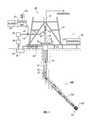
- FIG. 1illustrates a drilling system made in accordance with one embodiment of the present disclosure
- FIG. 2illustrates an exemplary bottom hole assembly made in accordance with one embodiment of the present disclosure
- FIG. 3illustrates an exemplary hole enlargement device made in accordance with one embodiment of the present disclosure.
- the present disclosurerelates to devices and methods for drilling wellbores with one or more pre-selected bore diameters.
- the teachings of the present disclosuremay be advantageously applied to “sliding” drilling operations that are performed by an automated drilling assembly. It will be understood, however, that the present disclosure may be applied to numerous other drilling strategies and systems.
- the present disclosureis susceptible to embodiments of different forms. There are shown in the drawings, and herein will be described in detail, specific embodiments of the present disclosure with the understanding that the present disclosure is to be considered an exemplification of the principles of the disclosure, and is not intended to limit the disclosure to that illustrated and described herein.
- FIG. 1there is shown an embodiment of a drilling system 10 utilizing a drilling assembly or bottom hole assembly (BHA) 100 made according to one embodiment of the present disclosure to drill wellbores. While a land-based rig is shown, these concepts and the methods are equally applicable to offshore drilling systems.
- the system 10 shown in FIG. 1has a drilling assembly 100 conveyed in a borehole 12 .
- a drill string 22includes a jointed tubular string 24 , which may be drill pipe or coiled tubing, extending downward from a rig 14 into the borehole 12 .
- a drill bit 102attached to the end of the drill string 22 , disintegrates the geological formations when it is rotated to drill the borehole 12 .
- the drill string 22which may be jointed tubulars or coiled tubing, may include power and/or data conductors such as wires for providing bidirectional communication and power transmission.
- the drill string 22is coupled to a drawworks 26 via a kelly joint 28 , swivel 30 and line 32 through a pulley (not shown).
- the operation of the drawworks 26is well known in the art and is thus not described in detail herein.
- a suitable drilling fluid 34 from a mud pit (source) 36is circulated under pressure through the drill string 22 by a mud pump 38 .
- the drilling fluid 34passes from the mud pump 38 into the drill string 22 via a desurger 40 , fluid line 42 and the kelly joint 28 .
- the drilling fluid 34is discharged at a borehole bottom 44 through an opening in the drill bit 102 .
- the drilling fluid 34circulates uphole through an annular space 46 between the drill string 22 and the borehole 12 and returns carrying drill cuttings to the mud pit 36 via a return line 48 .
- a sensor S 1preferably placed in the line 42 , provides information about the fluid flow rate.
- a surface torque sensor S 2 and a sensor S 3 associated with the drill string 22provide information about the torque and the rotational speed of the drill string 22 . Additionally, a sensor S 4 associated with line 32 is used to provide the hook load of the drill string 22 .
- a surface controller 50receives signals from the downhole sensors and devices via a sensor 52 placed in the fluid line 42 and signals from sensors S 1 , S 2 , S 3 , hook load sensor S 4 , and any other sensors used in the system, and processes such signals according to programmed instructions provided to the surface controller 50 .
- the surface controller 50displays desired drilling parameters and other information on a display/monitor 54 and is utilized by an operator to control the drilling operations.
- the surface controller 50contains a computer, memory for storing data, recorder for recording data and other peripherals.
- the surface controller 50processes data according to programmed instructions and responds to user commands entered through a suitable device, such as a keyboard or a touch screen.
- the controller 50is preferably adapted to activate alarms 56 when certain unsafe or undesirable operating conditions occur.
- the BHA 100may automatically drill a wellbore having one or more selected bore diameters.
- automatedit is meant that the BHA 100 using downhole and/or surface intelligence and based on received sensor data input may control drilling direction using pre-programmed instructions. Drilling direction may be controlled utilizing a selected wellbore trajectory, one or more parameters relating to the formation, and/or one or more parameters relating to operation of the BHA 100 .
- One suitable drilling assembly named VERTITRAK®is available from Baker Hughes Incorporated.
- Some suitable exemplary drilling systems and steering devicesare discussed in U.S. Pat. Nos. 6,513,606 and 6,427,783, which are commonly assigned and which are hereby incorporated by reference for all purposes. It should be understood that the present disclosure is not limited to any particular drilling system.
- the BHA 100includes a drill bit 102 , a hole enlargement device 110 , a steering device 115 , a drilling motor 120 , a sensor sub 130 , a bidirectional communication and power module (BCPM) 140 , a stabilizer 150 , and a formation evaluation (FE) sub 160 .
- the hole enlargement device 110is integrated into a motor flex shaft 122 using a suitable electrical and mechanical connection 124 .
- the hole enlargement device 110may be a separate module that is mated to the motor flex shaft 122 using an appropriate mechanical joint and data and/or power connectors.
- the hole enlargement device 110is structurally incorporated in the flex shaft 122 itself.
- the steering device 115 and the hole enlargement device 110may share a common power supply, e.g., hydraulic or electric, and a common communication system.
- the BHA 100includes a power and/or data transmission line (not shown).
- the power and/or data transmission line (not shown)may extend along the entire length of the BHA 100 up to and including the hole enlargement device 110 and the drill bit 102 .
- Exemplary uplinks, downlinks and data and/or power transmission arrangementsare described in commonly owned and U.S. patent application Ser. No. 11/282,995, filed Nov. 18, 2005, now U.S. Pat. No. 7,708,086, issued May 4, 2010, which is hereby incorporated by reference for all purposes.
- embodiments of the present disclosureinclude BHAs adapted for automated “sliding drilling” and that can selectively enlarge the diameter of the wellbore being drilled.
- the hole enlargement devicemay include expandable cutting elements or blades. Surface personnel may use the power and/or data link between the hole enlargement device and BCPM and the surface to determine the position of the hole enlargement device blades (i.e., expanded or retracted) and to issue instructions to cause the blades to move between an expanded and retracted position.
- the hole enlargement device bladescan be shifted to an expanded position as the BHA penetrates a swelling formation such as shale and later returned to a retracted position as the BHA penetrates into a more stable formation.
- One suitable hole enlargement deviceis referred to as an “underreamer” in the art.
- the hole enlargement device 200includes a plurality of circumferentially spaced-apart cutting elements 210 that may, in real-time, be extended and retracted by an actuation unit 220 . When extended, the cutting elements 210 scrape, break up and disintegrate the wellbore surface formed initially by the drill bit 102 .
- the actuation unit 220utilizes pressurized hydraulic fluid as the energizing medium.
- the actuation unit 220may include a piston 222 disposed in a cylinder 223 , an oil reservoir 224 , and valves 226 that regulate flow into and out of the cylinder 223 .
- a cutting element 210is fixed on each piston 222 .
- the actuation unit 220uses “clean” hydraulic fluid that flows within a closed loop.
- the hydraulic fluidmay be pressurized using pumps and/or by the pressurized drilling fluid flowing through a bore 228 .
- a common power source(not shown), such as a pump and associated fluid conduits, supplies pressurized fluid for both the hole enlargement device 110 and the steering unit 115 ( FIG. 2 ).
- the hole enlargement device 110 and the steering unit 115may be considered as hydraulically operatively connected.
- An electronics package 230controls valve components such as actuators (not shown) in response to surface and/or downhole commands and transmits signals indicative of the condition and operation of the hole enlargement device 200 .
- a position sensor 232 fixed adjacent to the cylinder 223provides an indication as to the radial position of the cutting elements 210 .
- the sensor 232may include electrical contacts that close when the cutting elements 210 are extended.
- the position sensor 232 and electronics package 230communicate with the BCPM 140 ( FIG. 2 ) via a line 234 .
- surface personnelmay transmit instructions from the surface that cause the electronics package 230 to operate the valve actuators for a particular action (e.g., extension or retraction of the cutting elements 210 ).
- a signal indicative of the position of the cutting elements 210is transmitted from the position sensor 232 via the line 234 to the BCPM 140 and, ultimately, to the surface where it may, for example, be displayed on display 54 ( FIG. 1 ).
- the cutting elements 210may be extended or retracted in situ during drilling or while drilling is interrupted.
- devicessuch as biasing elements such as springs 238 may be used to maintain the cutting elements 210 in a retracted position.
- the actuation unit 220may use devices such as an electric motor or employ shape-changing materials such as magnetostrictive or piezoelectric materials to translate the cutting elements 210 between the extended and retracted positions.
- the actuation unit 220may be an “open” system that utilizes the circulating drilling fluid to displace the piston 222 within the cylinder 223 .
- embodiments of the hole enlargement device 200may utilize mechanical, electromechanical, electrical, pneumatic and hydraulic systems to move the cutting elements 210 .
- the hole enlargement device 200is shown as integral with the motor flex shaft 122 , in other embodiments, the hole enlargement device 200 may be integral with the drill bit 102 .
- the hole enlargement device 200may be adapted to connect to the drill bit 102 .
- the drill bit 102 bodymay be modified to include radially expandable cutting elements (not shown).
- the hole enlargement device 200may be positioned in a sub, positioned between the steering device 130 and the drill bit 102 , or elsewhere along the drill string 22 ( FIG. 1 ).
- the hole enlargement device 200may be rotated by a separate motor (e.g., mud motor, electric motor, pneumatic motor) or by drill string rotation.
- a separate motore.g., mud motor, electric motor, pneumatic motor
- embodiments of the present disclosureare utilized during “automated” drilling.
- the drillingis automated using downhole intelligence that control drilling direction in response to directional data (e.g., azimuth, inclination, north) measured by onboard sensors.
- the intelligencemay be in the form of instructions programmed into a downhole controller that is operatively coupled to the steering device. Discussed in greater detail below are illustrative tools and components suitable for such applications.
- the data used to control the BHA 100is obtained by a variety of tools positioned along the BHA 100 , such as the sensor sub 130 and the formation evaluation sub 160 .
- the sensor sub 130may include sensors for measuring near-bit direction (e.g., BHA azimuth and inclination, BHA coordinates, etc.), dual rotary azimuthal gamma ray, bore and annular pressure (flow-on and flow-off), temperature, vibration/dynamics, multiple propagation resistivity, and sensors and tools for making rotary directional surveys.
- the formation evaluation sub 160may include sensors for determining parameters of interest relating to the formation, borehole, geophysical characteristics, borehole fluids and boundary conditions. These sensors include formation evaluation sensors (e.g., resistivity, dielectric constant, water saturation, porosity, density and permeability), sensors for measuring borehole parameters (e.g., borehole size, and borehole roughness), sensors for measuring geophysical parameters (e.g., acoustic velocity and acoustic travel time), sensors for measuring borehole fluid parameters (e.g., viscosity, density, clarity, rheology, pH level, and gas, oil and water contents), and boundary condition sensors, sensors for measuring physical and chemical properties of the borehole fluid.
- formation evaluation sensorse.g., resistivity, dielectric constant, water saturation, porosity, density and permeability
- sensors for measuring borehole parameterse.g., borehole size, and borehole roughness
- geophysical parameterse.g., acoustic velocity and acoustic travel time
- the subs 130 and 160may include one or memory modules and a battery pack module to store and provide backup electrical power that may be placed at any suitable location in the BHA 100 .
- Additional modules and sensorsmay be provided depending upon the specific drilling requirements.
- Such exemplary sensorsmay include an rpm sensor, a weight-on-bit sensor, sensors for measuring mud motor parameters (e.g., mud motor stator temperature, differential pressure across a mud motor, and fluid flow rate through a mud motor), and sensors for measuring vibration, whirl, radial displacement, stick-slip, torque, shock, vibration, strain, stress, bending moment, bit bounce, axial thrust, friction and radial thrust.
- the near bit inclination devicesmay include three (3) axis accelerometers, gyroscopic devices and signal processing circuitry as generally known in the art. These sensors may be positioned in the subs 130 and 160 , distributed along the drill pipe, in the drill bit 102 ( FIG. 1 ) and along the BHA 100 . Further, while subs 130 and 160 are described as separate modules, in certain embodiments, the sensors described above may be consolidated into a single sub or separated into three or more subs.
- the term “sub”refers merely to any supporting housing or structure and is not intended to mean a particular tool or configuration.
- a processor 132processes the data collected by the sensor sub 130 and formation evaluation sub 160 and transmit appropriate control signals to the steering device 115 .
- pads 117 of the steering device 115extend to apply selected amounts of force to the wellbore wall (not shown). The applied forces create a force vector that urges the drill bit 102 in a selected drilling direction.
- the processor 132may also be programmed to issue instructions to the hole enlargement device 110 and/or transmit data to the surface.
- the processor 132may be configured to decimate data, digitize data, and include suitable PLCs.
- the processor 132may include one or more microprocessors that uses a computer program implemented on a suitable machine-readable medium that enables the processor 132 to perform the control and processing.
- the machine-readable mediummay include ROMs, EPROMs, EAROMs, Flash memories and optical disks. Other equipment such as power and data buses, power supplies, and the like, will be apparent to one skilled in the art. While the processor 132 is shown in the sensor sub 130 , the processor 132 may be positioned elsewhere in the BHA 100 . Moreover, other electronics, such as electronics that drive or operate actuators for valves and other devices, may also be positioned along the BHA 100 .
- the bidirectional data communication and power module (“BCPM”) 140transmits control signals between the BHA 100 and the surface as well as supplies electrical power to the BHA 100 .
- the BCPM 140provides electrical power to devices such as the hole enlargement device 110 and steering device 115 and establishes two-way data communication between the processor 132 and surface devices such as the controller 50 ( FIG. 1 ).
- hole enlargement device 110 and the steering device 115may be considered electrically operatively connected.
- the BCPM 140generates power using a mud-driven alternator (not shown) and the data signals are generated by a mud pulser (not shown).
- the mud-driven power generation unitsare known in the art and thus not described in greater detail.
- Suitable two-way communication linksmay use hard wires (e.g., electrical conductors, fiber optics), acoustic signals, EM or RF.
- hard wirese.g., electrical conductors, fiber optics
- EM or RFe.g., RF-Fi Protected Access (WPA)
- EM or RFRF-Fi Protected Access
- the BHA 100also includes the stabilizer 150 , which has one or more stabilizing elements 152 , and is disposed along the BHA 100 to provide lateral stability to the BHA 100 .
- the stabilizing elements 152may be fixed or adjustable.
- the BHA 100is conveyed into the wellbore 12 from the rig 14 .
- the steering device 115steers the drill bit 102 in a selected direction.
- a mud motor 104rotates the drill bit 102 (sliding drilling) and the drill string 22 remains relatively rotationally stationary as the drill bit 102 disintegrates the formation to form the wellbore.
- the drilling directionmay follow a preset trajectory that is programmed into a surface and/or downhole controller (e.g., controller 50 and/or controller 132 ).
- the controller(s)use directional data received from downhole directional sensors to determine the orientation of the BHA 100 , compute course correction instructions if needed, and transmit those instructions to the steering device 115 .
- the radial position (e.g., extended or retracted) of the cutting elements 210is displayed on the display 54 .
- surface personnelmay desire to enlarge the diameter of the well being drilled. Such an action may be due to encountering a formation susceptible to swelling, due to a need for providing a suitable annular space for cement or for some other drilling consideration.
- Surface personnelmay transmit a signal using the communication downlink (e.g., mud pulse telemetry) that causes the downhole electronics 230 to energize the actuation unit 220 , which in turn extends the cutting elements 210 radially outward.
- the position sensor 232transmits a signal indicative of the extended position, which is displayed on display 54 .
- surface personnelare affirmatively notified that the hole enlargement device 110 is extended and operational.
- the drill bit 102which now acts as a type of pilot bit, drills the wellbore to a first diameter while the extended cutting elements 210 enlarge the wellbore to a second, larger diameter.
- the BHA 100under control of the processors 50 and/or 132 continues to automatically drill the formation by adjusting or controlling the steering device 115 as needed to maintain a desired wellbore path or trajectory. If at a later point personnel decide that an enlarged wellbore is not necessary, a signal transmitted from the surface to the downhole electronics 230 causes the cutting elements 210 to retract.
- the position sensor 232upon sensing the retraction, generates a corresponding signal, which is ultimately displayed on display 54 .
- the above drilling operationis merely illustrative.
- the surface and/or downhole processorsmay be programmed to automatically extend and retract the cutting elements as needed.
- teachings of the present applicationmay readily be applied to other drilling systems.
- Such other drillings systemsinclude BHAs coupled to a rotating drilling string and BHAs, wherein rotation of the drill string is superimposed on the mud motor rotation.
Landscapes
- Engineering & Computer Science (AREA)
- Geology (AREA)
- Life Sciences & Earth Sciences (AREA)
- Mining & Mineral Resources (AREA)
- Physics & Mathematics (AREA)
- Environmental & Geological Engineering (AREA)
- Fluid Mechanics (AREA)
- General Life Sciences & Earth Sciences (AREA)
- Geochemistry & Mineralogy (AREA)
- Mechanical Engineering (AREA)
- Remote Sensing (AREA)
- Geophysics (AREA)
- Earth Drilling (AREA)
- Processing Of Stones Or Stones Resemblance Materials (AREA)
Abstract
Description
Claims (21)
Priority Applications (3)
| Application Number | Priority Date | Filing Date | Title |
|---|---|---|---|
| US11/681,370US9187959B2 (en) | 2006-03-02 | 2007-03-02 | Automated steerable hole enlargement drilling device and methods |
| US12/689,452US8875810B2 (en) | 2006-03-02 | 2010-01-19 | Hole enlargement drilling device and methods for using same |
| US14/532,549US9482054B2 (en) | 2006-03-02 | 2014-11-04 | Hole enlargement drilling device and methods for using same |
Applications Claiming Priority (2)
| Application Number | Priority Date | Filing Date | Title |
|---|---|---|---|
| US77832906P | 2006-03-02 | 2006-03-02 | |
| US11/681,370US9187959B2 (en) | 2006-03-02 | 2007-03-02 | Automated steerable hole enlargement drilling device and methods |
Related Child Applications (1)
| Application Number | Title | Priority Date | Filing Date |
|---|---|---|---|
| US12/689,452Continuation-In-PartUS8875810B2 (en) | 2006-03-02 | 2010-01-19 | Hole enlargement drilling device and methods for using same |
Publications (2)
| Publication Number | Publication Date |
|---|---|
| US20070205022A1 US20070205022A1 (en) | 2007-09-06 |
| US9187959B2true US9187959B2 (en) | 2015-11-17 |
Family
ID=38337682
Family Applications (1)
| Application Number | Title | Priority Date | Filing Date |
|---|---|---|---|
| US11/681,370ActiveUS9187959B2 (en) | 2006-03-02 | 2007-03-02 | Automated steerable hole enlargement drilling device and methods |
Country Status (5)
| Country | Link |
|---|---|
| US (1) | US9187959B2 (en) |
| CA (1) | CA2644442C (en) |
| GB (1) | GB2449594B (en) |
| NO (1) | NO20083865L (en) |
| WO (1) | WO2007103245A2 (en) |
Cited By (16)
| Publication number | Priority date | Publication date | Assignee | Title |
|---|---|---|---|---|
| US10316619B2 (en) | 2017-03-16 | 2019-06-11 | Saudi Arabian Oil Company | Systems and methods for stage cementing |
| US10378298B2 (en) | 2017-08-02 | 2019-08-13 | Saudi Arabian Oil Company | Vibration-induced installation of wellbore casing |
| US10378339B2 (en) | 2017-11-08 | 2019-08-13 | Saudi Arabian Oil Company | Method and apparatus for controlling wellbore operations |
| US10487604B2 (en) | 2017-08-02 | 2019-11-26 | Saudi Arabian Oil Company | Vibration-induced installation of wellbore casing |
| US10544648B2 (en) | 2017-04-12 | 2020-01-28 | Saudi Arabian Oil Company | Systems and methods for sealing a wellbore |
| US10557330B2 (en) | 2017-04-24 | 2020-02-11 | Saudi Arabian Oil Company | Interchangeable wellbore cleaning modules |
| US10597962B2 (en) | 2017-09-28 | 2020-03-24 | Saudi Arabian Oil Company | Drilling with a whipstock system |
| US10612362B2 (en) | 2018-05-18 | 2020-04-07 | Saudi Arabian Oil Company | Coiled tubing multifunctional quad-axial visual monitoring and recording |
| US10689914B2 (en) | 2018-03-21 | 2020-06-23 | Saudi Arabian Oil Company | Opening a wellbore with a smart hole-opener |
| US10689913B2 (en) | 2018-03-21 | 2020-06-23 | Saudi Arabian Oil Company | Supporting a string within a wellbore with a smart stabilizer |
| US10794170B2 (en) | 2018-04-24 | 2020-10-06 | Saudi Arabian Oil Company | Smart system for selection of wellbore drilling fluid loss circulation material |
| US20210388679A1 (en)* | 2020-06-11 | 2021-12-16 | Schlumberger Technology Corporation | Downhole tools having radially extendable elements |
| US11299968B2 (en) | 2020-04-06 | 2022-04-12 | Saudi Arabian Oil Company | Reducing wellbore annular pressure with a release system |
| US11396789B2 (en) | 2020-07-28 | 2022-07-26 | Saudi Arabian Oil Company | Isolating a wellbore with a wellbore isolation system |
| US11414942B2 (en) | 2020-10-14 | 2022-08-16 | Saudi Arabian Oil Company | Packer installation systems and related methods |
| US11624265B1 (en) | 2021-11-12 | 2023-04-11 | Saudi Arabian Oil Company | Cutting pipes in wellbores using downhole autonomous jet cutting tools |
Families Citing this family (36)
| Publication number | Priority date | Publication date | Assignee | Title |
|---|---|---|---|---|
| US7036611B2 (en) | 2002-07-30 | 2006-05-02 | Baker Hughes Incorporated | Expandable reamer apparatus for enlarging boreholes while drilling and methods of use |
| US8875810B2 (en)* | 2006-03-02 | 2014-11-04 | Baker Hughes Incorporated | Hole enlargement drilling device and methods for using same |
| US9187959B2 (en) | 2006-03-02 | 2015-11-17 | Baker Hughes Incorporated | Automated steerable hole enlargement drilling device and methods |
| US8190369B2 (en) | 2006-09-28 | 2012-05-29 | Baker Hughes Incorporated | System and method for stress field based wellbore steering |
| US7962287B2 (en)* | 2007-07-23 | 2011-06-14 | Schlumberger Technology Corporation | Method and apparatus for optimizing magnetic signals and detecting casing and resistivity |
| US8720604B2 (en)* | 2007-08-15 | 2014-05-13 | Schlumberger Technology Corporation | Method and system for steering a directional drilling system |
| US8763726B2 (en)* | 2007-08-15 | 2014-07-01 | Schlumberger Technology Corporation | Drill bit gauge pad control |
| US8757294B2 (en)* | 2007-08-15 | 2014-06-24 | Schlumberger Technology Corporation | System and method for controlling a drilling system for drilling a borehole in an earth formation |
| US8534380B2 (en) | 2007-08-15 | 2013-09-17 | Schlumberger Technology Corporation | System and method for directional drilling a borehole with a rotary drilling system |
| US8727036B2 (en)* | 2007-08-15 | 2014-05-20 | Schlumberger Technology Corporation | System and method for drilling |
| US8066085B2 (en) | 2007-08-15 | 2011-11-29 | Schlumberger Technology Corporation | Stochastic bit noise control |
| US7836975B2 (en)* | 2007-10-24 | 2010-11-23 | Schlumberger Technology Corporation | Morphable bit |
| US8540035B2 (en) | 2008-05-05 | 2013-09-24 | Weatherford/Lamb, Inc. | Extendable cutting tools for use in a wellbore |
| GB2460096B (en) | 2008-06-27 | 2010-04-07 | Wajid Rasheed | Expansion and calliper tool |
| EP2483510A2 (en) | 2009-09-30 | 2012-08-08 | Baker Hughes Incorporated | Remotely controlled apparatus for downhole applications and methods of operation |
| WO2011162999A2 (en) | 2010-06-24 | 2011-12-29 | Baker Hughes Incorporated | Cutting elements for earth-boring tools, earth-boring tools including such cutting elements, and methods of forming cutting elements for earth-boring tools |
| CN103210169A (en) | 2010-10-04 | 2013-07-17 | 贝克休斯公司 | Status indicators for use in earth-boring tools having expandable members and methods of making and using such status indicators and earth-boring tools |
| US9464480B2 (en) | 2011-03-10 | 2016-10-11 | Halliburton Energy Services, Inc. | Magnetostrictive motor for a borehole assembly |
| US8844635B2 (en) | 2011-05-26 | 2014-09-30 | Baker Hughes Incorporated | Corrodible triggering elements for use with subterranean borehole tools having expandable members and related methods |
| US8960333B2 (en) | 2011-12-15 | 2015-02-24 | Baker Hughes Incorporated | Selectively actuating expandable reamers and related methods |
| US9267331B2 (en) | 2011-12-15 | 2016-02-23 | Baker Hughes Incorporated | Expandable reamers and methods of using expandable reamers |
| US9512706B2 (en) | 2012-03-02 | 2016-12-06 | Schlumberger Technology Corporation | Agent registration in dynamic phase machine automation system |
| US9493991B2 (en) | 2012-04-02 | 2016-11-15 | Baker Hughes Incorporated | Cutting structures, tools for use in subterranean boreholes including cutting structures and related methods |
| US9759014B2 (en) | 2013-05-13 | 2017-09-12 | Baker Hughes Incorporated | Earth-boring tools including movable formation-engaging structures and related methods |
| US9399892B2 (en) | 2013-05-13 | 2016-07-26 | Baker Hughes Incorporated | Earth-boring tools including movable cutting elements and related methods |
| WO2016011085A1 (en)* | 2014-07-14 | 2016-01-21 | Aarbakke Innovation A.S. | Wellbore intervention tool for penetrating obstructions in a wellbore |
| US10087739B2 (en)* | 2015-12-28 | 2018-10-02 | Baker Hughes, A Ge Company, Llc | Coiled tubing-based milling assembly |
| CN107882510A (en)* | 2016-09-30 | 2018-04-06 | 上海城地建设股份有限公司 | A kind of boring drill bit device of reducing and construction method |
| US11952842B2 (en) | 2017-05-24 | 2024-04-09 | Baker Hughes Incorporated | Sophisticated contour for downhole tools |
| US11174681B2 (en) | 2017-08-31 | 2021-11-16 | Halliburton Energy Services, Inc. | Push-the-bit bottom hole assembly with reamer |
| WO2019045716A1 (en) | 2017-08-31 | 2019-03-07 | Halliburton Energy Services, Inc. | DOWNHOLE ASSEMBLY WITH DIRECTIONAL TRAPPER WITH RIFLE |
| US10954772B2 (en)* | 2017-09-14 | 2021-03-23 | Baker Hughes, A Ge Company, Llc | Automated optimization of downhole tools during underreaming while drilling operations |
| WO2020005286A1 (en)* | 2018-06-29 | 2020-01-02 | Halliburton Energy Services, Inc. | Hybrid drill bit gauge configuration |
| WO2020145940A1 (en)* | 2019-01-07 | 2020-07-16 | Halliburton Energy Services, Inc. | System and method for communicating with a downhole tool |
| AU2021107346B4 (en)* | 2020-11-02 | 2022-05-19 | Timothy Mcclure | Method for Installing an Earthing System |
| US11840898B2 (en)* | 2021-12-21 | 2023-12-12 | Baker Hughes Oilfield Operations Llc | Intelligent section mill, method, and system |
Citations (122)
| Publication number | Priority date | Publication date | Assignee | Title |
|---|---|---|---|---|
| US1406348A (en)* | 1920-09-04 | 1922-02-14 | Clyde S Corrigan | Deep-well reamer |
| US1678075A (en) | 1928-07-24 | Expansible rotary ttnderreamer | ||
| US2069482A (en) | 1935-04-18 | 1937-02-02 | James I Seay | Well reamer |
| US2177721A (en) | 1938-02-23 | 1939-10-31 | Baash Ross Tool Co | Wall scraper |
| US2344598A (en) | 1942-01-06 | 1944-03-21 | Walter L Church | Wall scraper and well logging tool |
| US2754089A (en) | 1954-02-08 | 1956-07-10 | Rotary Oil Tool Company | Rotary expansible drill bits |
| US2758819A (en) | 1954-08-25 | 1956-08-14 | Rotary Oil Tool Company | Hydraulically expansible drill bits |
| US2834578A (en) | 1955-09-12 | 1958-05-13 | Charles J Carr | Reamer |
| US2882019A (en) | 1956-10-19 | 1959-04-14 | Charles J Carr | Self-cleaning collapsible reamer |
| US3105562A (en) | 1960-07-15 | 1963-10-01 | Gulf Oil Corp | Underreaming tool |
| US3123162A (en) | 1964-03-03 | Xsill string stabilizer | ||
| US3126065A (en) | 1964-03-24 | Chadderdon | ||
| US3211232A (en) | 1961-03-31 | 1965-10-12 | Otis Eng Co | Pressure operated sleeve valve and operator |
| US3224507A (en) | 1962-09-07 | 1965-12-21 | Servco Co | Expansible subsurface well bore apparatus |
| US3425500A (en) | 1966-11-25 | 1969-02-04 | Benjamin H Fuchs | Expandable underreamer |
| US3433313A (en) | 1966-05-10 | 1969-03-18 | Cicero C Brown | Under-reaming tool |
| US3556233A (en) | 1968-10-04 | 1971-01-19 | Lafayette E Gilreath | Well reamer with extensible and retractable reamer elements |
| US4403659A (en) | 1981-04-13 | 1983-09-13 | Schlumberger Technology Corporation | Pressure controlled reversing valve |
| US4403664A (en) | 1980-08-28 | 1983-09-13 | Richard Sullinger | Earth boring machine and method |
| US4413682A (en) | 1982-06-07 | 1983-11-08 | Baker Oil Tools, Inc. | Method and apparatus for installing a cementing float shoe on the bottom of a well casing |
| US4458761A (en) | 1982-09-09 | 1984-07-10 | Smith International, Inc. | Underreamer with adjustable arm extension |
| US4545441A (en) | 1981-02-25 | 1985-10-08 | Williamson Kirk E | Drill bits with polycrystalline diamond cutting elements mounted on serrated supports pressed in drill head |
| US4548282A (en)* | 1982-05-22 | 1985-10-22 | Wirth Maschinen-Und Bohrgerate-Fabrik Gmbh | Method for sinking boreholes |
| US4589504A (en) | 1984-07-27 | 1986-05-20 | Diamant Boart Societe Anonyme | Well bore enlarger |
| US4660657A (en) | 1985-10-21 | 1987-04-28 | Smith International, Inc. | Underreamer |
| US4690229A (en) | 1986-01-22 | 1987-09-01 | Raney Richard C | Radially stabilized drill bit |
| US4693328A (en) | 1986-06-09 | 1987-09-15 | Smith International, Inc. | Expandable well drilling tool |
| EP0246789A2 (en) | 1986-05-16 | 1987-11-25 | Nl Petroleum Products Limited | Cutter for a rotary drill bit, rotary drill bit with such a cutter, and method of manufacturing such a cutter |
| US4842083A (en) | 1986-01-22 | 1989-06-27 | Raney Richard C | Drill bit stabilizer |
| US4848490A (en) | 1986-07-03 | 1989-07-18 | Anderson Charles A | Downhole stabilizers |
| US4854403A (en) | 1987-04-08 | 1989-08-08 | Eastman Christensen Company | Stabilizer for deep well drilling tools |
| US4862974A (en)* | 1988-12-07 | 1989-09-05 | Amoco Corporation | Downhole drilling assembly, apparatus and method utilizing drilling motor and stabilizer |
| US4884477A (en) | 1988-03-31 | 1989-12-05 | Eastman Christensen Company | Rotary drill bit with abrasion and erosion resistant facing |
| US4889197A (en) | 1987-07-30 | 1989-12-26 | Norsk Hydro A.S. | Hydraulic operated underreamer |
| US5060736A (en)* | 1990-08-20 | 1991-10-29 | Smith International, Inc. | Steerable tool underreaming system |
| US5103919A (en)* | 1990-10-04 | 1992-04-14 | Amoco Corporation | Method of determining the rotational orientation of a downhole tool |
| US5139098A (en) | 1991-09-26 | 1992-08-18 | John Blake | Combined drill and underreamer tool |
| US5211241A (en) | 1991-04-01 | 1993-05-18 | Otis Engineering Corporation | Variable flow sliding sleeve valve and positioning shifting tool therefor |
| US5220963A (en) | 1989-12-22 | 1993-06-22 | Patton Consulting, Inc. | System for controlled drilling of boreholes along planned profile |
| US5224558A (en) | 1990-12-12 | 1993-07-06 | Paul Lee | Down hole drilling tool control mechanism |
| US5265684A (en) | 1991-11-27 | 1993-11-30 | Baroid Technology, Inc. | Downhole adjustable stabilizer and method |
| US5305833A (en) | 1993-02-16 | 1994-04-26 | Halliburton Company | Shifting tool for sliding sleeve valves |
| US5307886A (en) | 1991-05-02 | 1994-05-03 | Hopper Hans P | Method for casing a hole drilled in a formation |
| US5318137A (en) | 1992-10-23 | 1994-06-07 | Halliburton Company | Method and apparatus for adjusting the position of stabilizer blades |
| US5318131A (en) | 1992-04-03 | 1994-06-07 | Baker Samuel F | Hydraulically actuated liner hanger arrangement and method |
| US5318138A (en) | 1992-10-23 | 1994-06-07 | Halliburton Company | Adjustable stabilizer |
| US5332048A (en) | 1992-10-23 | 1994-07-26 | Halliburton Company | Method and apparatus for automatic closed loop drilling system |
| US5343963A (en) | 1990-07-09 | 1994-09-06 | Bouldin Brett W | Method and apparatus for providing controlled force transference to a wellbore tool |
| US5361859A (en) | 1993-02-12 | 1994-11-08 | Baker Hughes Incorporated | Expandable gage bit for drilling and method of drilling |
| US5368114A (en) | 1992-04-30 | 1994-11-29 | Tandberg; Geir | Under-reaming tool for boreholes |
| US5375662A (en) | 1991-08-12 | 1994-12-27 | Halliburton Company | Hydraulic setting sleeve |
| US5394951A (en) | 1993-12-13 | 1995-03-07 | Camco International Inc. | Bottom hole drilling assembly |
| US5425423A (en) | 1994-03-22 | 1995-06-20 | Bestline Liner Systems | Well completion tool and process |
| US5437308A (en) | 1988-12-30 | 1995-08-01 | Institut Francais Du Petrole | Device for remotely actuating equipment comprising a bean-needle system |
| US5553678A (en) | 1991-08-30 | 1996-09-10 | Camco International Inc. | Modulated bias units for steerable rotary drilling systems |
| US5560440A (en) | 1993-02-12 | 1996-10-01 | Baker Hughes Incorporated | Bit for subterranean drilling fabricated from separately-formed major components |
| US5603386A (en)* | 1992-03-05 | 1997-02-18 | Ledge 101 Limited | Downhole tool for controlling the drilling course of a borehole |
| US5740864A (en) | 1996-01-29 | 1998-04-21 | Baker Hughes Incorporated | One-trip packer setting and whipstock-orienting method and apparatus |
| US5787999A (en) | 1996-07-01 | 1998-08-04 | Holte; Ardis L. | Drill bit with set of underreamer arms |
| US5788000A (en) | 1995-10-31 | 1998-08-04 | Elf Aquitaine Production | Stabilizer-reamer for drilling an oil well |
| US5823254A (en) | 1996-05-02 | 1998-10-20 | Bestline Liner Systems, Inc. | Well completion tool |
| GB2328964A (en) | 1997-09-08 | 1999-03-10 | Baker Hughes Inc | Drag bit with gauge pads of varying aggressiveness |
| US5887655A (en) | 1993-09-10 | 1999-03-30 | Weatherford/Lamb, Inc | Wellbore milling and drilling |
| US5899268A (en) | 1986-01-06 | 1999-05-04 | Baker Hughes Incorporated | Downhole milling tool |
| US6000479A (en) | 1998-01-27 | 1999-12-14 | Western Atlas International, Inc. | Slimhole drill system |
| US6039131A (en) | 1997-08-25 | 2000-03-21 | Smith International, Inc. | Directional drift and drill PDC drill bit |
| US6059051A (en)* | 1996-11-04 | 2000-05-09 | Baker Hughes Incorporated | Integrated directional under-reamer and stabilizer |
| WO2000031371A1 (en) | 1998-11-19 | 2000-06-02 | Andergauge Limited | Downhole tool with extendable members |
| US6070677A (en) | 1997-12-02 | 2000-06-06 | I.D.A. Corporation | Method and apparatus for enhancing production from a wellbore hole |
| US6109354A (en) | 1996-04-18 | 2000-08-29 | Halliburton Energy Services, Inc. | Circulating valve responsive to fluid flow rate therethrough and associated methods of servicing a well |
| US6109372A (en)* | 1999-03-15 | 2000-08-29 | Schlumberger Technology Corporation | Rotary steerable well drilling system utilizing hydraulic servo-loop |
| US6116336A (en) | 1996-09-18 | 2000-09-12 | Weatherford/Lamb, Inc. | Wellbore mill system |
| EP1036913A1 (en) | 1999-03-18 | 2000-09-20 | Camco International (UK) Limited | A method of applying a wear--resistant layer to a surface of a downhole component |
| US6131675A (en) | 1998-09-08 | 2000-10-17 | Baker Hughes Incorporated | Combination mill and drill bit |
| EP1044314A1 (en) | 1997-12-04 | 2000-10-18 | Halliburton Energy Services, Inc. | Drilling system including eccentric adjustable diameter blade stabilizer |
| US6189631B1 (en) | 1998-11-12 | 2001-02-20 | Adel Sheshtawy | Drilling tool with extendable elements |
| US6196336B1 (en)* | 1995-10-09 | 2001-03-06 | Baker Hughes Incorporated | Method and apparatus for drilling boreholes in earth formations (drilling liner systems) |
| US6289999B1 (en) | 1998-10-30 | 2001-09-18 | Smith International, Inc. | Fluid flow control devices and methods for selective actuation of valves and hydraulic drilling tools |
| US20010042643A1 (en) | 2000-01-12 | 2001-11-22 | Volker Krueger | Steerable modular drilling assembly |
| US6325151B1 (en) | 2000-04-28 | 2001-12-04 | Baker Hughes Incorporated | Packer annulus differential pressure valve |
| US6378632B1 (en) | 1998-10-30 | 2002-04-30 | Smith International, Inc. | Remotely operable hydraulic underreamer |
| US20020070052A1 (en) | 2000-12-07 | 2002-06-13 | Armell Richard A. | Reaming tool with radially extending blades |
| US6419033B1 (en) | 1999-12-10 | 2002-07-16 | Baker Hughes Incorporated | Apparatus and method for simultaneous drilling and casing wellbores |
| US6513606B1 (en) | 1998-11-10 | 2003-02-04 | Baker Hughes Incorporated | Self-controlled directional drilling systems and methods |
| US20030029644A1 (en) | 2001-08-08 | 2003-02-13 | Hoffmaster Carl M. | Advanced expandable reaming tool |
| US20030051881A1 (en) | 2000-03-02 | 2003-03-20 | Vinegar Harold J. | Electro-hydraulically pressurized downhole valve actuator |
| US20030070842A1 (en)* | 2001-10-12 | 2003-04-17 | Bailey Thomas F. | Methods and apparatus to control downhole tools |
| US20030079913A1 (en)* | 2000-06-27 | 2003-05-01 | Halliburton Energy Services, Inc. | Apparatus and method for drilling and reaming a borehole |
| US6609579B2 (en)* | 1997-01-30 | 2003-08-26 | Baker Hughes Incorporated | Drilling assembly with a steering device for coiled-tubing operations |
| US6629570B1 (en) | 1998-05-15 | 2003-10-07 | Philip Head | Method of downhole drilling and apparatus therefor |
| US6668949B1 (en)* | 1999-10-21 | 2003-12-30 | Allen Kent Rives | Underreamer and method of use |
| US6668936B2 (en) | 2000-09-07 | 2003-12-30 | Halliburton Energy Services, Inc. | Hydraulic control system for downhole tools |
| US6679328B2 (en) | 1999-07-27 | 2004-01-20 | Baker Hughes Incorporated | Reverse section milling method and apparatus |
| US6705413B1 (en)* | 1999-02-23 | 2004-03-16 | Tesco Corporation | Drilling with casing |
| US6708785B1 (en) | 1999-03-05 | 2004-03-23 | Mark Alexander Russell | Fluid controlled adjustable down-hole tool |
| US6732817B2 (en) | 2002-02-19 | 2004-05-11 | Smith International, Inc. | Expandable underreamer/stabilizer |
| US20040134687A1 (en)* | 2002-07-30 | 2004-07-15 | Radford Steven R. | Expandable reamer apparatus for enlarging boreholes while drilling and methods of use |
| US20040149431A1 (en)* | 2001-11-14 | 2004-08-05 | Halliburton Energy Services, Inc. | Method and apparatus for a monodiameter wellbore, monodiameter casing and monobore |
| WO2004097163A1 (en)* | 2003-04-30 | 2004-11-11 | Andergauge Limited | Downhole tool having radially extendable members |
| US6848518B2 (en) | 2001-09-18 | 2005-02-01 | Halliburton Energy Services, Inc. | Steerable underreaming bottom hole assembly and method |
| US20050056463A1 (en)* | 2003-09-15 | 2005-03-17 | Baker Hughes Incorporated | Steerable bit assembly and methods |
| US20050126826A1 (en) | 2003-12-12 | 2005-06-16 | Moriarty Keith A. | Directional casing and liner drilling with mud motor |
| US20050139393A1 (en) | 2003-12-29 | 2005-06-30 | Noble Drilling Corporation | Turbine generator system and method |
| US20050197777A1 (en)* | 2004-03-04 | 2005-09-08 | Rodney Paul F. | Method and system to model, measure, recalibrate, and optimize control of the drilling of a borehole |
| US20050211470A1 (en) | 2004-03-27 | 2005-09-29 | Schlumberger Technology Corporation | Bottom hole assembly |
| US20060124354A1 (en)* | 2004-11-19 | 2006-06-15 | Baker Hughes Incorporated | Modular drilling apparatus with power and/or data transmission |
| US7096978B2 (en) | 1999-08-26 | 2006-08-29 | Baker Hughes Incorporated | Drill bits with reduced exposure of cutters |
| US20060237234A1 (en)* | 2005-04-25 | 2006-10-26 | Dennis Tool Company | Earth boring tool |
| WO2006112763A1 (en) | 2005-04-21 | 2006-10-26 | Loef Uno | Drilling tool and method for down-the-hole drilling |
| GB2401384B (en) | 2003-05-08 | 2007-01-17 | Smith International | Expandable downhole tool and drilling assembly |
| US20070205022A1 (en) | 2006-03-02 | 2007-09-06 | Baker Hughes Incorporated | Automated steerable hole enlargement drilling device and methods |
| US7303022B2 (en)* | 2002-10-11 | 2007-12-04 | Weatherford/Lamb, Inc. | Wired casing |
| US7306056B2 (en)* | 2003-11-05 | 2007-12-11 | Baker Hughes Incorporated | Directional cased hole side track method applying rotary closed loop system and casing mill |
| US7395882B2 (en) | 2004-02-19 | 2008-07-08 | Baker Hughes Incorporated | Casing and liner drilling bits |
| US7481280B2 (en)* | 2005-06-20 | 2009-01-27 | 1243939 Alberta Ltd. | Method and apparatus for conducting earth borehole operations using coiled casing |
| US7513318B2 (en) | 2002-02-19 | 2009-04-07 | Smith International, Inc. | Steerable underreamer/stabilizer assembly and method |
| US20090242275A1 (en) | 2008-03-28 | 2009-10-01 | Radford Steven R | Stabilizer and reamer system having extensible blades and bearing pads and method of using same |
| US20090294178A1 (en) | 2008-05-01 | 2009-12-03 | Radford Steven R | Stabilizer and reamer system having extensible blades and bearing pads and method of using same |
| US20100139981A1 (en) | 2006-03-02 | 2010-06-10 | Baker Hughes Incorporated | Hole Enlargement Drilling Device and Methods for Using Same |
| US7757784B2 (en)* | 2003-11-17 | 2010-07-20 | Baker Hughes Incorporated | Drilling methods utilizing independently deployable multiple tubular strings |
| US20100282511A1 (en) | 2007-06-05 | 2010-11-11 | Halliburton Energy Services, Inc. | Wired Smart Reamer |
| US20110284233A1 (en) | 2010-05-21 | 2011-11-24 | Smith International, Inc. | Hydraulic Actuation of a Downhole Tool Assembly |
- 2007
- 2007-03-02USUS11/681,370patent/US9187959B2/enactiveActive
- 2007-03-02WOPCT/US2007/005486patent/WO2007103245A2/enactiveApplication Filing
- 2007-03-02CACA2644442Apatent/CA2644442C/ennot_activeExpired - Fee Related
- 2007-03-02GBGB0816355Apatent/GB2449594B/ennot_activeExpired - Fee Related
- 2008
- 2008-09-09NONO20083865Apatent/NO20083865L/ennot_activeApplication Discontinuation
Patent Citations (139)
| Publication number | Priority date | Publication date | Assignee | Title |
|---|---|---|---|---|
| US3123162A (en) | 1964-03-03 | Xsill string stabilizer | ||
| US1678075A (en) | 1928-07-24 | Expansible rotary ttnderreamer | ||
| US3126065A (en) | 1964-03-24 | Chadderdon | ||
| US1406348A (en)* | 1920-09-04 | 1922-02-14 | Clyde S Corrigan | Deep-well reamer |
| US2069482A (en) | 1935-04-18 | 1937-02-02 | James I Seay | Well reamer |
| US2177721A (en) | 1938-02-23 | 1939-10-31 | Baash Ross Tool Co | Wall scraper |
| US2344598A (en) | 1942-01-06 | 1944-03-21 | Walter L Church | Wall scraper and well logging tool |
| US2754089A (en) | 1954-02-08 | 1956-07-10 | Rotary Oil Tool Company | Rotary expansible drill bits |
| US2758819A (en) | 1954-08-25 | 1956-08-14 | Rotary Oil Tool Company | Hydraulically expansible drill bits |
| US2834578A (en) | 1955-09-12 | 1958-05-13 | Charles J Carr | Reamer |
| US2882019A (en) | 1956-10-19 | 1959-04-14 | Charles J Carr | Self-cleaning collapsible reamer |
| US3105562A (en) | 1960-07-15 | 1963-10-01 | Gulf Oil Corp | Underreaming tool |
| US3211232A (en) | 1961-03-31 | 1965-10-12 | Otis Eng Co | Pressure operated sleeve valve and operator |
| US3224507A (en) | 1962-09-07 | 1965-12-21 | Servco Co | Expansible subsurface well bore apparatus |
| US3433313A (en) | 1966-05-10 | 1969-03-18 | Cicero C Brown | Under-reaming tool |
| US3425500A (en) | 1966-11-25 | 1969-02-04 | Benjamin H Fuchs | Expandable underreamer |
| US3556233A (en) | 1968-10-04 | 1971-01-19 | Lafayette E Gilreath | Well reamer with extensible and retractable reamer elements |
| US4403664A (en) | 1980-08-28 | 1983-09-13 | Richard Sullinger | Earth boring machine and method |
| US4545441A (en) | 1981-02-25 | 1985-10-08 | Williamson Kirk E | Drill bits with polycrystalline diamond cutting elements mounted on serrated supports pressed in drill head |
| US4403659A (en) | 1981-04-13 | 1983-09-13 | Schlumberger Technology Corporation | Pressure controlled reversing valve |
| US4548282A (en)* | 1982-05-22 | 1985-10-22 | Wirth Maschinen-Und Bohrgerate-Fabrik Gmbh | Method for sinking boreholes |
| US4413682A (en) | 1982-06-07 | 1983-11-08 | Baker Oil Tools, Inc. | Method and apparatus for installing a cementing float shoe on the bottom of a well casing |
| US4458761A (en) | 1982-09-09 | 1984-07-10 | Smith International, Inc. | Underreamer with adjustable arm extension |
| US4589504A (en) | 1984-07-27 | 1986-05-20 | Diamant Boart Societe Anonyme | Well bore enlarger |
| US4660657A (en) | 1985-10-21 | 1987-04-28 | Smith International, Inc. | Underreamer |
| US5899268A (en) | 1986-01-06 | 1999-05-04 | Baker Hughes Incorporated | Downhole milling tool |
| US4690229A (en) | 1986-01-22 | 1987-09-01 | Raney Richard C | Radially stabilized drill bit |
| US4842083A (en) | 1986-01-22 | 1989-06-27 | Raney Richard C | Drill bit stabilizer |
| EP0246789A2 (en) | 1986-05-16 | 1987-11-25 | Nl Petroleum Products Limited | Cutter for a rotary drill bit, rotary drill bit with such a cutter, and method of manufacturing such a cutter |
| US4693328A (en) | 1986-06-09 | 1987-09-15 | Smith International, Inc. | Expandable well drilling tool |
| US4848490A (en) | 1986-07-03 | 1989-07-18 | Anderson Charles A | Downhole stabilizers |
| US4854403A (en) | 1987-04-08 | 1989-08-08 | Eastman Christensen Company | Stabilizer for deep well drilling tools |
| US4889197A (en) | 1987-07-30 | 1989-12-26 | Norsk Hydro A.S. | Hydraulic operated underreamer |
| US4884477A (en) | 1988-03-31 | 1989-12-05 | Eastman Christensen Company | Rotary drill bit with abrasion and erosion resistant facing |
| US4862974A (en)* | 1988-12-07 | 1989-09-05 | Amoco Corporation | Downhole drilling assembly, apparatus and method utilizing drilling motor and stabilizer |
| US5437308A (en) | 1988-12-30 | 1995-08-01 | Institut Francais Du Petrole | Device for remotely actuating equipment comprising a bean-needle system |
| US5220963A (en) | 1989-12-22 | 1993-06-22 | Patton Consulting, Inc. | System for controlled drilling of boreholes along planned profile |
| US5343963A (en) | 1990-07-09 | 1994-09-06 | Bouldin Brett W | Method and apparatus for providing controlled force transference to a wellbore tool |
| US5060736A (en)* | 1990-08-20 | 1991-10-29 | Smith International, Inc. | Steerable tool underreaming system |
| US5103919A (en)* | 1990-10-04 | 1992-04-14 | Amoco Corporation | Method of determining the rotational orientation of a downhole tool |
| US5224558A (en) | 1990-12-12 | 1993-07-06 | Paul Lee | Down hole drilling tool control mechanism |
| US5211241A (en) | 1991-04-01 | 1993-05-18 | Otis Engineering Corporation | Variable flow sliding sleeve valve and positioning shifting tool therefor |
| US5307886A (en) | 1991-05-02 | 1994-05-03 | Hopper Hans P | Method for casing a hole drilled in a formation |
| US5375662A (en) | 1991-08-12 | 1994-12-27 | Halliburton Company | Hydraulic setting sleeve |
| US5553678A (en) | 1991-08-30 | 1996-09-10 | Camco International Inc. | Modulated bias units for steerable rotary drilling systems |
| US5139098A (en) | 1991-09-26 | 1992-08-18 | John Blake | Combined drill and underreamer tool |
| US5265684A (en) | 1991-11-27 | 1993-11-30 | Baroid Technology, Inc. | Downhole adjustable stabilizer and method |
| US5293945A (en) | 1991-11-27 | 1994-03-15 | Baroid Technology, Inc. | Downhole adjustable stabilizer |
| US5603386A (en)* | 1992-03-05 | 1997-02-18 | Ledge 101 Limited | Downhole tool for controlling the drilling course of a borehole |
| US5318131A (en) | 1992-04-03 | 1994-06-07 | Baker Samuel F | Hydraulically actuated liner hanger arrangement and method |
| US5368114A (en) | 1992-04-30 | 1994-11-29 | Tandberg; Geir | Under-reaming tool for boreholes |
| US5318137A (en) | 1992-10-23 | 1994-06-07 | Halliburton Company | Method and apparatus for adjusting the position of stabilizer blades |
| US5318138A (en) | 1992-10-23 | 1994-06-07 | Halliburton Company | Adjustable stabilizer |
| US5332048A (en) | 1992-10-23 | 1994-07-26 | Halliburton Company | Method and apparatus for automatic closed loop drilling system |
| US5560440A (en) | 1993-02-12 | 1996-10-01 | Baker Hughes Incorporated | Bit for subterranean drilling fabricated from separately-formed major components |
| US5361859A (en) | 1993-02-12 | 1994-11-08 | Baker Hughes Incorporated | Expandable gage bit for drilling and method of drilling |
| US5305833A (en) | 1993-02-16 | 1994-04-26 | Halliburton Company | Shifting tool for sliding sleeve valves |
| US5887655A (en) | 1993-09-10 | 1999-03-30 | Weatherford/Lamb, Inc | Wellbore milling and drilling |
| US5394951A (en) | 1993-12-13 | 1995-03-07 | Camco International Inc. | Bottom hole drilling assembly |
| US5425423A (en) | 1994-03-22 | 1995-06-20 | Bestline Liner Systems | Well completion tool and process |
| US6196336B1 (en)* | 1995-10-09 | 2001-03-06 | Baker Hughes Incorporated | Method and apparatus for drilling boreholes in earth formations (drilling liner systems) |
| US5788000A (en) | 1995-10-31 | 1998-08-04 | Elf Aquitaine Production | Stabilizer-reamer for drilling an oil well |
| US5740864A (en) | 1996-01-29 | 1998-04-21 | Baker Hughes Incorporated | One-trip packer setting and whipstock-orienting method and apparatus |
| US6109354A (en) | 1996-04-18 | 2000-08-29 | Halliburton Energy Services, Inc. | Circulating valve responsive to fluid flow rate therethrough and associated methods of servicing a well |
| US5823254A (en) | 1996-05-02 | 1998-10-20 | Bestline Liner Systems, Inc. | Well completion tool |
| US5787999A (en) | 1996-07-01 | 1998-08-04 | Holte; Ardis L. | Drill bit with set of underreamer arms |
| US6116336A (en) | 1996-09-18 | 2000-09-12 | Weatherford/Lamb, Inc. | Wellbore mill system |
| US6059051A (en)* | 1996-11-04 | 2000-05-09 | Baker Hughes Incorporated | Integrated directional under-reamer and stabilizer |
| GB2319046B (en) | 1996-11-04 | 2001-07-04 | Baker Hughes Inc | A drilling tool |
| US6609579B2 (en)* | 1997-01-30 | 2003-08-26 | Baker Hughes Incorporated | Drilling assembly with a steering device for coiled-tubing operations |
| US6039131A (en) | 1997-08-25 | 2000-03-21 | Smith International, Inc. | Directional drift and drill PDC drill bit |
| GB2328964A (en) | 1997-09-08 | 1999-03-10 | Baker Hughes Inc | Drag bit with gauge pads of varying aggressiveness |
| US6070677A (en) | 1997-12-02 | 2000-06-06 | I.D.A. Corporation | Method and apparatus for enhancing production from a wellbore hole |
| US6227312B1 (en) | 1997-12-04 | 2001-05-08 | Halliburton Energy Services, Inc. | Drilling system and method |
| US6488104B1 (en)* | 1997-12-04 | 2002-12-03 | Halliburton Energy Services, Inc. | Directional drilling assembly and method |
| EP1044314A1 (en) | 1997-12-04 | 2000-10-18 | Halliburton Energy Services, Inc. | Drilling system including eccentric adjustable diameter blade stabilizer |
| US6494272B1 (en) | 1997-12-04 | 2002-12-17 | Halliburton Energy Services, Inc. | Drilling system utilizing eccentric adjustable diameter blade stabilizer and winged reamer |
| US6213226B1 (en) | 1997-12-04 | 2001-04-10 | Halliburton Energy Services, Inc. | Directional drilling assembly and method |
| US6000479A (en) | 1998-01-27 | 1999-12-14 | Western Atlas International, Inc. | Slimhole drill system |
| US20040050589A1 (en) | 1998-05-15 | 2004-03-18 | Philip Head | Method of downhole drilling and apparatus therefor |
| US6629570B1 (en) | 1998-05-15 | 2003-10-07 | Philip Head | Method of downhole drilling and apparatus therefor |
| US6131675A (en) | 1998-09-08 | 2000-10-17 | Baker Hughes Incorporated | Combination mill and drill bit |
| US6289999B1 (en) | 1998-10-30 | 2001-09-18 | Smith International, Inc. | Fluid flow control devices and methods for selective actuation of valves and hydraulic drilling tools |
| US6378632B1 (en) | 1998-10-30 | 2002-04-30 | Smith International, Inc. | Remotely operable hydraulic underreamer |
| GB2344122B (en) | 1998-10-30 | 2003-04-09 | Smith International | Fluid flow control devices and methods for selective actuation of valves and hydraulic drilling tools |
| US6513606B1 (en) | 1998-11-10 | 2003-02-04 | Baker Hughes Incorporated | Self-controlled directional drilling systems and methods |
| US6189631B1 (en) | 1998-11-12 | 2001-02-20 | Adel Sheshtawy | Drilling tool with extendable elements |
| GB2344607B (en) | 1998-11-12 | 2003-02-19 | Adel Sheshtawy | Drilling tool with extendable elements |
| WO2000031371A1 (en) | 1998-11-19 | 2000-06-02 | Andergauge Limited | Downhole tool with extendable members |
| US6615933B1 (en) | 1998-11-19 | 2003-09-09 | Andergauge Limited | Downhole tool with extendable members |
| US6705413B1 (en)* | 1999-02-23 | 2004-03-16 | Tesco Corporation | Drilling with casing |
| US6708785B1 (en) | 1999-03-05 | 2004-03-23 | Mark Alexander Russell | Fluid controlled adjustable down-hole tool |
| US6109372A (en)* | 1999-03-15 | 2000-08-29 | Schlumberger Technology Corporation | Rotary steerable well drilling system utilizing hydraulic servo-loop |
| EP1036913A1 (en) | 1999-03-18 | 2000-09-20 | Camco International (UK) Limited | A method of applying a wear--resistant layer to a surface of a downhole component |
| US6679328B2 (en) | 1999-07-27 | 2004-01-20 | Baker Hughes Incorporated | Reverse section milling method and apparatus |
| US7096978B2 (en) | 1999-08-26 | 2006-08-29 | Baker Hughes Incorporated | Drill bits with reduced exposure of cutters |
| US6668949B1 (en)* | 1999-10-21 | 2003-12-30 | Allen Kent Rives | Underreamer and method of use |
| GB2357101B (en) | 1999-12-10 | 2002-07-17 | Baker Hughes Inc | Apparatus and method for simultaneous drilling and casing wellbores |
| US6419033B1 (en) | 1999-12-10 | 2002-07-16 | Baker Hughes Incorporated | Apparatus and method for simultaneous drilling and casing wellbores |
| US6427783B2 (en) | 2000-01-12 | 2002-08-06 | Baker Hughes Incorporated | Steerable modular drilling assembly |
| US20010042643A1 (en) | 2000-01-12 | 2001-11-22 | Volker Krueger | Steerable modular drilling assembly |
| US20030051881A1 (en) | 2000-03-02 | 2003-03-20 | Vinegar Harold J. | Electro-hydraulically pressurized downhole valve actuator |
| US6325151B1 (en) | 2000-04-28 | 2001-12-04 | Baker Hughes Incorporated | Packer annulus differential pressure valve |
| US6920944B2 (en)* | 2000-06-27 | 2005-07-26 | Halliburton Energy Services, Inc. | Apparatus and method for drilling and reaming a borehole |
| US20030079913A1 (en)* | 2000-06-27 | 2003-05-01 | Halliburton Energy Services, Inc. | Apparatus and method for drilling and reaming a borehole |
| US6668936B2 (en) | 2000-09-07 | 2003-12-30 | Halliburton Energy Services, Inc. | Hydraulic control system for downhole tools |
| US20020070052A1 (en) | 2000-12-07 | 2002-06-13 | Armell Richard A. | Reaming tool with radially extending blades |
| US20030029644A1 (en) | 2001-08-08 | 2003-02-13 | Hoffmaster Carl M. | Advanced expandable reaming tool |
| US6848518B2 (en) | 2001-09-18 | 2005-02-01 | Halliburton Energy Services, Inc. | Steerable underreaming bottom hole assembly and method |
| US20030070842A1 (en)* | 2001-10-12 | 2003-04-17 | Bailey Thomas F. | Methods and apparatus to control downhole tools |
| US20040149431A1 (en)* | 2001-11-14 | 2004-08-05 | Halliburton Energy Services, Inc. | Method and apparatus for a monodiameter wellbore, monodiameter casing and monobore |
| US7314099B2 (en) | 2002-02-19 | 2008-01-01 | Smith International, Inc. | Selectively actuatable expandable underreamer/stablizer |
| US7513318B2 (en) | 2002-02-19 | 2009-04-07 | Smith International, Inc. | Steerable underreamer/stabilizer assembly and method |
| US6732817B2 (en) | 2002-02-19 | 2004-05-11 | Smith International, Inc. | Expandable underreamer/stabilizer |
| US7048078B2 (en) | 2002-02-19 | 2006-05-23 | Smith International, Inc. | Expandable underreamer/stabilizer |
| US20040134687A1 (en)* | 2002-07-30 | 2004-07-15 | Radford Steven R. | Expandable reamer apparatus for enlarging boreholes while drilling and methods of use |
| US7303022B2 (en)* | 2002-10-11 | 2007-12-04 | Weatherford/Lamb, Inc. | Wired casing |
| WO2004097163A1 (en)* | 2003-04-30 | 2004-11-11 | Andergauge Limited | Downhole tool having radially extendable members |
| GB2401384B (en) | 2003-05-08 | 2007-01-17 | Smith International | Expandable downhole tool and drilling assembly |
| US20050056463A1 (en)* | 2003-09-15 | 2005-03-17 | Baker Hughes Incorporated | Steerable bit assembly and methods |
| US7287604B2 (en)* | 2003-09-15 | 2007-10-30 | Baker Hughes Incorporated | Steerable bit assembly and methods |
| US7306056B2 (en)* | 2003-11-05 | 2007-12-11 | Baker Hughes Incorporated | Directional cased hole side track method applying rotary closed loop system and casing mill |
| US7757784B2 (en)* | 2003-11-17 | 2010-07-20 | Baker Hughes Incorporated | Drilling methods utilizing independently deployable multiple tubular strings |
| US20050126826A1 (en) | 2003-12-12 | 2005-06-16 | Moriarty Keith A. | Directional casing and liner drilling with mud motor |
| US20050139393A1 (en) | 2003-12-29 | 2005-06-30 | Noble Drilling Corporation | Turbine generator system and method |
| US7395882B2 (en) | 2004-02-19 | 2008-07-08 | Baker Hughes Incorporated | Casing and liner drilling bits |
| US20050197777A1 (en)* | 2004-03-04 | 2005-09-08 | Rodney Paul F. | Method and system to model, measure, recalibrate, and optimize control of the drilling of a borehole |
| US20050211470A1 (en) | 2004-03-27 | 2005-09-29 | Schlumberger Technology Corporation | Bottom hole assembly |
| US20060124354A1 (en)* | 2004-11-19 | 2006-06-15 | Baker Hughes Incorporated | Modular drilling apparatus with power and/or data transmission |
| US7708086B2 (en) | 2004-11-19 | 2010-05-04 | Baker Hughes Incorporated | Modular drilling apparatus with power and/or data transmission |
| WO2006112763A1 (en) | 2005-04-21 | 2006-10-26 | Loef Uno | Drilling tool and method for down-the-hole drilling |
| US20060237234A1 (en)* | 2005-04-25 | 2006-10-26 | Dennis Tool Company | Earth boring tool |
| US7481280B2 (en)* | 2005-06-20 | 2009-01-27 | 1243939 Alberta Ltd. | Method and apparatus for conducting earth borehole operations using coiled casing |
| US20100139981A1 (en) | 2006-03-02 | 2010-06-10 | Baker Hughes Incorporated | Hole Enlargement Drilling Device and Methods for Using Same |
| US20070205022A1 (en) | 2006-03-02 | 2007-09-06 | Baker Hughes Incorporated | Automated steerable hole enlargement drilling device and methods |
| US20100282511A1 (en) | 2007-06-05 | 2010-11-11 | Halliburton Energy Services, Inc. | Wired Smart Reamer |
| US20090242275A1 (en) | 2008-03-28 | 2009-10-01 | Radford Steven R | Stabilizer and reamer system having extensible blades and bearing pads and method of using same |
| US20090294178A1 (en) | 2008-05-01 | 2009-12-03 | Radford Steven R | Stabilizer and reamer system having extensible blades and bearing pads and method of using same |
| US20110284233A1 (en) | 2010-05-21 | 2011-11-24 | Smith International, Inc. | Hydraulic Actuation of a Downhole Tool Assembly |
Non-Patent Citations (4)
| Title |
|---|
| International Preliminary Report on Patentability for International Application No. PCT/US2007/005486 dated Sep. 2, 2008, 6 pages. |
| International Search Report for International Application No. PCT/US2007/005486 dated Aug. 28, 2007, 5 pages. |
| International Written Opinion for International Application No. PCT/US2007/005486 dated Aug. 28, 2007, 5 pages. |
| Rasheed, Wajid et al., SPE 92623,"Reducing Risk and Cost in Diverse Well Construction Applications: Eccentric Deice Drills Concentric Hole and Offers a Viable Alternative to Underreamers", 2004. |
Cited By (20)
| Publication number | Priority date | Publication date | Assignee | Title |
|---|---|---|---|---|
| US10316619B2 (en) | 2017-03-16 | 2019-06-11 | Saudi Arabian Oil Company | Systems and methods for stage cementing |
| US10544648B2 (en) | 2017-04-12 | 2020-01-28 | Saudi Arabian Oil Company | Systems and methods for sealing a wellbore |
| US10557330B2 (en) | 2017-04-24 | 2020-02-11 | Saudi Arabian Oil Company | Interchangeable wellbore cleaning modules |
| US10378298B2 (en) | 2017-08-02 | 2019-08-13 | Saudi Arabian Oil Company | Vibration-induced installation of wellbore casing |
| US10487604B2 (en) | 2017-08-02 | 2019-11-26 | Saudi Arabian Oil Company | Vibration-induced installation of wellbore casing |
| US10920517B2 (en) | 2017-08-02 | 2021-02-16 | Saudi Arabian Oil Company | Vibration-induced installation of wellbore casing |
| US10597962B2 (en) | 2017-09-28 | 2020-03-24 | Saudi Arabian Oil Company | Drilling with a whipstock system |
| US10378339B2 (en) | 2017-11-08 | 2019-08-13 | Saudi Arabian Oil Company | Method and apparatus for controlling wellbore operations |
| US10689914B2 (en) | 2018-03-21 | 2020-06-23 | Saudi Arabian Oil Company | Opening a wellbore with a smart hole-opener |
| US10689913B2 (en) | 2018-03-21 | 2020-06-23 | Saudi Arabian Oil Company | Supporting a string within a wellbore with a smart stabilizer |
| US10794170B2 (en) | 2018-04-24 | 2020-10-06 | Saudi Arabian Oil Company | Smart system for selection of wellbore drilling fluid loss circulation material |
| US11268369B2 (en) | 2018-04-24 | 2022-03-08 | Saudi Arabian Oil Company | Smart system for selection of wellbore drilling fluid loss circulation material |
| US10612362B2 (en) | 2018-05-18 | 2020-04-07 | Saudi Arabian Oil Company | Coiled tubing multifunctional quad-axial visual monitoring and recording |
| US11299968B2 (en) | 2020-04-06 | 2022-04-12 | Saudi Arabian Oil Company | Reducing wellbore annular pressure with a release system |
| US20210388679A1 (en)* | 2020-06-11 | 2021-12-16 | Schlumberger Technology Corporation | Downhole tools having radially extendable elements |
| US11795763B2 (en)* | 2020-06-11 | 2023-10-24 | Schlumberger Technology Corporation | Downhole tools having radially extendable elements |
| US12435575B2 (en) | 2020-06-11 | 2025-10-07 | Schlumberger Technology Corporation | Downhole tools having radially extendable elements |
| US11396789B2 (en) | 2020-07-28 | 2022-07-26 | Saudi Arabian Oil Company | Isolating a wellbore with a wellbore isolation system |
| US11414942B2 (en) | 2020-10-14 | 2022-08-16 | Saudi Arabian Oil Company | Packer installation systems and related methods |
| US11624265B1 (en) | 2021-11-12 | 2023-04-11 | Saudi Arabian Oil Company | Cutting pipes in wellbores using downhole autonomous jet cutting tools |
Also Published As
| Publication number | Publication date |
|---|---|
| WO2007103245A2 (en) | 2007-09-13 |
| CA2644442A1 (en) | 2007-09-13 |
| GB0816355D0 (en) | 2008-10-15 |
| GB2449594A (en) | 2008-11-26 |
| CA2644442C (en) | 2013-04-23 |
| GB2449594B (en) | 2010-11-17 |
| WO2007103245A3 (en) | 2007-11-01 |
| NO20083865L (en) | 2008-10-01 |
| US20070205022A1 (en) | 2007-09-06 |
Similar Documents
| Publication | Publication Date | Title |
|---|---|---|
| US9187959B2 (en) | Automated steerable hole enlargement drilling device and methods | |
| US9482054B2 (en) | Hole enlargement drilling device and methods for using same | |
| US8360172B2 (en) | Steering device for downhole tools | |
| US6913095B2 (en) | Closed loop drilling assembly with electronics outside a non-rotating sleeve | |
| US7556105B2 (en) | Closed loop drilling assembly with electronics outside a non-rotating sleeve | |
| US7866415B2 (en) | Steering device for downhole tools | |
| US6419033B1 (en) | Apparatus and method for simultaneous drilling and casing wellbores | |
| CA2587884C (en) | Modular drilling apparatus with power and/or data transmission | |
| US10907465B2 (en) | Closed-loop drilling parameter control | |
| US9016401B2 (en) | Modular rotary steerable actuators, steering tools, and rotary steerable drilling systems with modular actuators | |
| US10954772B2 (en) | Automated optimization of downhole tools during underreaming while drilling operations | |
| EP2864574A2 (en) | Instrumented drilling system | |
| US8056649B2 (en) | Apparatus and methods for drilling wellbores that utilize a detachable reamer | |
| WO2008004999A1 (en) | Closed loop drilling assembly with electronics outside a non-rotating sleeve |
Legal Events
| Date | Code | Title | Description |
|---|---|---|---|
| AS | Assignment | Owner name:BAKER HUGHES INCORPORATED, TEXAS Free format text:ASSIGNMENT OF ASSIGNORS INTEREST;ASSIGNORS:TREVIRANUS, JOACHIM;FREYER, CARSTEN;OPPELAAR, HANS-ROBERT;SIGNING DATES FROM 20070306 TO 20070309;REEL/FRAME:019221/0342 Owner name:BAKER HUGHES INCORPORATED, TEXAS Free format text:ASSIGNMENT OF ASSIGNORS INTEREST;ASSIGNORS:TREVIRANUS, JOACHIM;FREYER, CARSTEN;OPPELAAR, HANS-ROBERT;REEL/FRAME:019221/0342;SIGNING DATES FROM 20070306 TO 20070309 | |
| FEPP | Fee payment procedure | Free format text:PAYOR NUMBER ASSIGNED (ORIGINAL EVENT CODE: ASPN); ENTITY STATUS OF PATENT OWNER: LARGE ENTITY | |
| STCF | Information on status: patent grant | Free format text:PATENTED CASE | |
| CC | Certificate of correction | ||
| MAFP | Maintenance fee payment | Free format text:PAYMENT OF MAINTENANCE FEE, 4TH YEAR, LARGE ENTITY (ORIGINAL EVENT CODE: M1551); ENTITY STATUS OF PATENT OWNER: LARGE ENTITY Year of fee payment:4 | |
| AS | Assignment | Owner name:BAKER HUGHES, A GE COMPANY, LLC., TEXAS Free format text:CHANGE OF NAME;ASSIGNOR:BAKER HUGHES INCORPORATED;REEL/FRAME:061493/0542 Effective date:20170703 | |
| AS | Assignment | Owner name:BAKER HUGHES HOLDINGS LLC, TEXAS Free format text:CHANGE OF NAME;ASSIGNOR:BAKER HUGHES, A GE COMPANY, LLC;REEL/FRAME:062020/0154 Effective date:20200413 | |
| MAFP | Maintenance fee payment | Free format text:PAYMENT OF MAINTENANCE FEE, 8TH YEAR, LARGE ENTITY (ORIGINAL EVENT CODE: M1552); ENTITY STATUS OF PATENT OWNER: LARGE ENTITY Year of fee payment:8 |