US9186806B2 - Handheld food slicer - Google Patents
Handheld food slicerDownload PDFInfo
- Publication number
- US9186806B2 US9186806B2US13/016,168US201113016168AUS9186806B2US 9186806 B2US9186806 B2US 9186806B2US 201113016168 AUS201113016168 AUS 201113016168AUS 9186806 B2US9186806 B2US 9186806B2
- Authority
- US
- United States
- Prior art keywords
- handle
- food
- fingers
- blade members
- distal end
- Prior art date
- Legal status (The legal status is an assumption and is not a legal conclusion. Google has not performed a legal analysis and makes no representation as to the accuracy of the status listed.)
- Active, expires
Links
Images


Classifications
- B—PERFORMING OPERATIONS; TRANSPORTING
- B26—HAND CUTTING TOOLS; CUTTING; SEVERING
- B26D—CUTTING; DETAILS COMMON TO MACHINES FOR PERFORATING, PUNCHING, CUTTING-OUT, STAMPING-OUT OR SEVERING
- B26D3/00—Cutting work characterised by the nature of the cut made; Apparatus therefor
- B26D3/16—Cutting rods or tubes transversely
- B26D3/161—Cutting rods or tubes transversely for obtaining more than one product at a time
- B—PERFORMING OPERATIONS; TRANSPORTING
- B26—HAND CUTTING TOOLS; CUTTING; SEVERING
- B26B—HAND-HELD CUTTING TOOLS NOT OTHERWISE PROVIDED FOR
- B26B13/00—Hand shears; Scissors
- B26B13/06—Hand shears; Scissors characterised by the shape of the blades
- B—PERFORMING OPERATIONS; TRANSPORTING
- B26—HAND CUTTING TOOLS; CUTTING; SEVERING
- B26B—HAND-HELD CUTTING TOOLS NOT OTHERWISE PROVIDED FOR
- B26B29/00—Guards or sheaths or guides for hand cutting tools; Arrangements for guiding hand cutting tools
- B26B29/06—Arrangements for guiding hand cutting tools
- B26B29/063—Food related applications
- B—PERFORMING OPERATIONS; TRANSPORTING
- B26—HAND CUTTING TOOLS; CUTTING; SEVERING
- B26B—HAND-HELD CUTTING TOOLS NOT OTHERWISE PROVIDED FOR
- B26B3/00—Hand knives with fixed blades
- B26B3/04—Hand knives with fixed blades for performing several incisions simultaneously; Multiple-blade knives
- B—PERFORMING OPERATIONS; TRANSPORTING
- B26—HAND CUTTING TOOLS; CUTTING; SEVERING
- B26D—CUTTING; DETAILS COMMON TO MACHINES FOR PERFORATING, PUNCHING, CUTTING-OUT, STAMPING-OUT OR SEVERING
- B26D1/00—Cutting through work characterised by the nature or movement of the cutting member or particular materials not otherwise provided for; Apparatus or machines therefor; Cutting members therefor
- B26D1/01—Cutting through work characterised by the nature or movement of the cutting member or particular materials not otherwise provided for; Apparatus or machines therefor; Cutting members therefor involving a cutting member which does not travel with the work
- B26D1/12—Cutting through work characterised by the nature or movement of the cutting member or particular materials not otherwise provided for; Apparatus or machines therefor; Cutting members therefor involving a cutting member which does not travel with the work having a cutting member moving about an axis
- B26D1/25—Cutting through work characterised by the nature or movement of the cutting member or particular materials not otherwise provided for; Apparatus or machines therefor; Cutting members therefor involving a cutting member which does not travel with the work having a cutting member moving about an axis with a non-circular cutting member
- B26D1/26—Cutting through work characterised by the nature or movement of the cutting member or particular materials not otherwise provided for; Apparatus or machines therefor; Cutting members therefor involving a cutting member which does not travel with the work having a cutting member moving about an axis with a non-circular cutting member moving about an axis substantially perpendicular to the line of cut
- B26D1/30—Cutting through work characterised by the nature or movement of the cutting member or particular materials not otherwise provided for; Apparatus or machines therefor; Cutting members therefor involving a cutting member which does not travel with the work having a cutting member moving about an axis with a non-circular cutting member moving about an axis substantially perpendicular to the line of cut with limited pivotal movement to effect cut
- B—PERFORMING OPERATIONS; TRANSPORTING
- B26—HAND CUTTING TOOLS; CUTTING; SEVERING
- B26D—CUTTING; DETAILS COMMON TO MACHINES FOR PERFORATING, PUNCHING, CUTTING-OUT, STAMPING-OUT OR SEVERING
- B26D3/00—Cutting work characterised by the nature of the cut made; Apparatus therefor
- B26D3/16—Cutting rods or tubes transversely
- B26D3/169—Hand held tube cutters
- B—PERFORMING OPERATIONS; TRANSPORTING
- B26—HAND CUTTING TOOLS; CUTTING; SEVERING
- B26D—CUTTING; DETAILS COMMON TO MACHINES FOR PERFORATING, PUNCHING, CUTTING-OUT, STAMPING-OUT OR SEVERING
- B26D5/00—Arrangements for operating and controlling machines or devices for cutting, cutting-out, stamping-out, punching, perforating, or severing by means other than cutting
- B26D5/08—Means for actuating the cutting member to effect the cut
- B26D5/10—Hand or foot actuated means
Definitions
- This disclosureis related to kitchen and/or food preparation tools, and more particularly, to a handheld device for slicing a food item, such as a banana.
- the handheld food slicers described hereinare particularly well suited for quickly and efficiently cutting food items into multiple slices and in a manner that allows for direct placement or depositing of the same at a location of interest, such as, for example, a prepared dish or a storage container.
- a handheld food slicermay be summarized as including a first handle having a plurality of elongated fingers, each finger separated from an adjacent finger by a blade receiving slot; a second handle movably coupled to the first handle; and a plurality of blade members coupled to the second handle in spaced alignment with the blade receiving slots to mate with the fingers to collectively define a food receiving passageway when the first and the second handles are in an expanded configuration in which a distal end of the first handle is at least partially spaced apart from a distal end of the second handle, the fingers of the first handle configured to pass through the food receiving passageway adjacent the blade members as the first and the second handles move from the expanded configuration towards a compressed configuration in which the distal end of each of the first and the second handles is relatively closer to the other.
- the handheld food slicermay further include a spring to bias the first and the second handles toward the expanded configuration.
- a pivot pinmay rotatably couple the second handle to the first handle.
- a curvilinear portion of each of the fingers of the first handlemay cooperate with the blade members to collectively define the food receiving passageway.
- the food receiving passagewaymay be substantially cylindrical.
- the distal end of the second handlemay be formed about a portion of each of the blade members to rigidly secure the blade members thereto.
- the blade membersmay be spaced equally along a central axis of the food receiving passageway or may be irregularly spaced along the central axis.
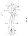
- FIG. 1is an isometric view of a handheld food slicer according to one embodiment, shown in an expanded configuration.
- FIG. 2is an exploded isometric view of the handheld food slicer of FIG. 1 .
- FIG. 3is a side elevational view of the handheld food slicer of FIG. 1 , shown in an expanded configuration.
- FIG. 4is a side elevational view of the handheld food slicer of FIG. 1 , shown in a compressed configuration.
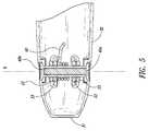
- FIG. 5is a partial cross-sectional view of taken along line 5 - 5 of FIG. 3 .
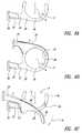
- FIG. 6Ais a partial side elevational view of a handheld food slicer according to another embodiment, shown with a handle removed.
- FIG. 6Bis a partial side elevational view of the handheld food slicer of FIG. 6A , shown in an expanded configuration.
- FIG. 6Cis a partial side elevational view of the handheld food slicer of FIG. 6A , shown in a compressed configuration.
- FIGS. 1-5illustrate a handheld food slicer 10 according to one embodiment which includes a first handle 20 , a second handle 30 and blade members 50 .
- the slicer 10further includes a pivot pin 40 for rotatably coupling the first handle 20 and the second handle 30 together about a central rotation axis R.
- a spring 60biases the handles 20 , 30 away from each other such that the slicer 10 is urged towards a generally expanded configuration E ( FIGS. 1 and 3 ) in which it is configured to insertably receive food items.
- a respective first end 21 , 31 of the first and the second handles 20 , 30interoperate to limit the range of movement of the slicer 10 to the expanded configuration E.
- the slicer 10is sized and its range of movement is limited such that it may fit comfortably in the grasp of an average sized hand throughout operation.
- a usermay effortlessly grasp the slicer 10 in one hand and apply a force or pressure to overcome the bias of the spring 60 and transition the slicer 10 from the expanded configuration E to a compressed configuration C ( FIG. 4 ).
- the spring 60urges the handles 20 , 30 back toward the expanded configuration E.
- the slicer 10is selectively and repeatably movable between the expanded configuration E and the compressed configuration C by the intermittent application of force or pressure (i.e., by squeezing and releasing the handles 20 , 30 ).
- Each of the handles 20 , 30is generally elongated and includes the respective first end 21 , 31 and a respective second end 22 , 32 (also referred to as a distal end).
- a connection structureis located proximate the first end 21 of the first handle 20 for coupling or mating the first handle 20 to the second handle 30 .
- the connection structuremay take the form of upstanding lugs 23 having pivot apertures 24 sized to receive the pivot pin 40 .
- the pivot pin 40may comprise, for example, a multi-part structure including complementary threaded pin members 40 a , 40 b .
- the lugs 23may be spaced apart at a distance sufficient to receive the spring 60 therebetween.
- the spring 60may be a helical torsion spring, a compression spring or the like.
- a connection structureis similarly located proximate the first end 31 of the second handle 30 .
- the connection structure of the second handle 30may likewise take the form of upstanding lugs 33 having pivot apertures 34 sized to receive the pivot pin 40 .
- the lugs 33 of the second handle 30may be positioned to fit between the lugs 23 of the first handle 20 , as illustrated in FIG. 5 , or in alternate embodiments, may be positioned to fall outside the lugs 23 of the first handle 20 .
- each of the handles 20 , 30is illustrated as including two separate lugs 23 , 33 , either handle 20 , 30 may include a single centrally located lug configured to be received between a pair of lugs of the opposing handle. In such an embodiment, two axially offset springs may be utilized instead of a single centrally located spring 60 .
- a plurality of elongated fingers 26are located at the second end 22 of the first handle 20 .
- the fingers 26are separated from each other by blade receiving slots 27 .
- the blade receiving slots 27have a width approximately equal to a corresponding blade member 50 coupled to the second end 32 of the second handle 30 .
- the illustrated embodimentincludes seven separate elongated fingers 26 , in other embodiments, the handheld food slicer 10 may include more or fewer fingers 26 .
- a width of the fingers 26may vary in accordance with a desired width of sliced food items. For example, thinner fingers 26 may be provided for applications in which thinly sliced food items are desired. Conversely, wider fingers 26 may be provided for applications in which thicker sliced food items are desired.
- the fingers 26may extend seamlessly from a base of the first handle 20 such that an outer surface of the first handle 20 appears uninterrupted.
- the second handle 30may also include a contoured outer surface that likewise appears uninterrupted and which may be complementarily shaped with respect to the first handle 20 .
- the outer surface of the handles 20 , 30may be complementarily shaped to reflect a food item for which the slicer 10 is particularly adapted to slice.
- a slicer 10 particularly adapted to receive and slice bananasmay include handles 20 , 30 having outer surfaces that reflect part of a banana, as illustrated in FIG. 3 .
- Other examplesinclude a carrot shaped slicer for slicing carrots, a celery shaped slicer for slicing celery and a cucumber shaped slicer for slicing cucumbers.
- blade members 50are coupled to the second end 32 of the second handle 30 .
- the blade members 50are spaced along a central axis A to align with the blade receiving slots 27 of the first handle 20 .
- the blade members 50 and hence blade receiving slots 27may be spaced in equal intervals, as illustrated, or in alternate embodiments may be irregularly spaced.
- Each of the blade members 50includes a blade edge profile 56 that generally corresponds to the shape of a food item to be sliced.
- each blade member 50may include an arcuate or a circular blade edge profile 56 corresponding to a shape of a food item having a generally circular cross-sectional profile, such as, for example, a banana.
- the blade members 50 and fingers 26are positioned to collectively define a food receiving passageway P that extends generally transverse to a length of the elongated handles 20 , 30 .
- the blade edge profiles 56may comprise closed profiles, such as complete circular or elliptical profiles. In other embodiments, the blade edge profiles 56 may comprise open profiles.
- the embodiment illustrated in FIGS. 6A-6Chas blade members 50 each including a u-shaped blade edge profile 56 which is bridged or capped by a portion 28 of a respective finger 26 of the first handle 20 to form the food receiving passageway P. In this manner, a portion 28 of the fingers 26 may cooperate with the blade members 50 to collectively define the food receiving passageway P.
- a curvilinear portion 28 of the fingers 26 of the first handle 20cooperates with the blade members 50 to collectively define a substantially cylindrical food receiving passageway P extending along central axis A.
- Each blade member 50further includes a structure for coupling to the second handle 30 .
- This structuremay comprise, for example, a protruding portion 52 adapted to be received by or otherwise coupled to the second handle 30 .
- the blade members 50may be attached to the second handle 30 by clips, snaps, detents or other fastening structures or may be formed integrally therewith.
- the second handle 30may be formed around the protruding portion 52 of each blade member 50 via a molding process.
- the blade members 50may further include one or more apertures 54 for receiving material of the second handle 30 during a molding process to facilitate secure attachment.
- the food slicer 10is configured to be held initially in an expanded configuration E.
- the second end 22 (or distal end) of the first handle 20 and the second end 32 (or distal end) of the second handle 30are spaced apart under the bias of spring 60 such that the fingers 26 of the first handle 20 are positioned to one side of the food receiving passageway P.
- the blade members 50align with and at least partially engage the blade receiving slots 27 between the fingers 26 .
- food itemsmay be inserted in the food receiving passageway P for subsequent slicing.
- a usermay grasp the slicer 10 with one hand and a food item with the other. The user may then insert the food item into the receiving passageway P and position the slicer 10 with the food item therein in various orientations prior to slicing. For example, a user may insert a banana into the food receiving passageway P and position the slicer 10 over a bowl of cereal for subsequent placement of sliced banana pieces in the bowl directly.
- the handheld food slicer 10is transitionable from the expanded configuration E to a compressed configuration C, as indicated by the arrow labeled 70 .
- the slicer 10may be moved to the compressed configuration C by grasping the slicer 10 in the palm of one's hand and squeezing the handles 20 , 30 to overcome the bias of the spring 60 and bring the second ends 22 , 32 (or distal ends) of the handles 20 , 30 relatively closer together.
- the spring 60may be sized and/or shaped such that the spring bias is easily overcome by a moderate squeezing action. In this manner, the slicer 10 is particularly well suited for one-handed operation.
- the fingers 26 of the first handle 20pass through the food receiving passageway P adjacent the blade members 50 .
- the fingers 26push the food item into engagement with the blade edge profile 56 of each blade member 50 .
- the blade members 50penetrate the food item and cut the same into sliced pieces.
- the slicer 10may be manipulated during the slicing process to various orientations. Accordingly, a user can selectively place sliced food products into storage containers or onto prepared dishes, for example, without additional handling.
- the slicer 10thus provides a particularly versatile food slicing mechanism.
Landscapes
- Engineering & Computer Science (AREA)
- Life Sciences & Earth Sciences (AREA)
- Forests & Forestry (AREA)
- Mechanical Engineering (AREA)
- Food Science & Technology (AREA)
- Food-Manufacturing Devices (AREA)
Abstract
Description
Claims (16)
Priority Applications (1)
| Application Number | Priority Date | Filing Date | Title |
|---|---|---|---|
| US13/016,168US9186806B2 (en) | 2010-02-11 | 2011-01-28 | Handheld food slicer |
Applications Claiming Priority (2)
| Application Number | Priority Date | Filing Date | Title |
|---|---|---|---|
| US30341910P | 2010-02-11 | 2010-02-11 | |
| US13/016,168US9186806B2 (en) | 2010-02-11 | 2011-01-28 | Handheld food slicer |
Publications (2)
| Publication Number | Publication Date |
|---|---|
| US20110192036A1 US20110192036A1 (en) | 2011-08-11 |
| US9186806B2true US9186806B2 (en) | 2015-11-17 |
Family
ID=43858046
Family Applications (1)
| Application Number | Title | Priority Date | Filing Date |
|---|---|---|---|
| US13/016,168Active2032-05-17US9186806B2 (en) | 2010-02-11 | 2011-01-28 | Handheld food slicer |
Country Status (7)
| Country | Link |
|---|---|
| US (1) | US9186806B2 (en) |
| EP (1) | EP2533954B1 (en) |
| AU (1) | AU2011216160B2 (en) |
| CA (1) | CA2788353C (en) |
| DK (1) | DK2533954T3 (en) |
| ES (1) | ES2496769T3 (en) |
| WO (1) | WO2011100126A1 (en) |
Cited By (3)
| Publication number | Priority date | Publication date | Assignee | Title |
|---|---|---|---|---|
| US20140208909A1 (en)* | 2013-01-25 | 2014-07-31 | Edlund Company, Llc | Food-Product Slicers Having Cammed Slicing-Cleaving Actions |
| US20170210022A1 (en)* | 2014-06-11 | 2017-07-27 | Imre Ivan Szilagyi | Apparatus for slicing rolled up crepes |
| USD863872S1 (en)* | 2018-10-25 | 2019-10-22 | Pian Chen | Melon cutter |
Families Citing this family (8)
| Publication number | Priority date | Publication date | Assignee | Title |
|---|---|---|---|---|
| US20120017731A1 (en)* | 2010-07-23 | 2012-01-26 | Mastroianni Michael R | Slicer for food items |
| US9242384B2 (en) | 2012-05-14 | 2016-01-26 | Culinary Expressions Inc. | Food slicer |
| CN103586917A (en)* | 2013-11-04 | 2014-02-19 | 杨杰 | Melon and fruit slicer |
| US9486098B2 (en)* | 2014-04-04 | 2016-11-08 | King's Flair Development Ltd. | Tool for preparing an avocado |
| CN105397857B (en)* | 2015-11-27 | 2018-03-23 | 南通江海港建设工程有限公司 | slicing device |
| CN106913186B (en)* | 2015-12-24 | 2019-08-13 | 科劲发展有限公司 | Food processing device |
| US10625434B1 (en)* | 2019-07-29 | 2020-04-21 | Dana Nadeau | Tomato dicing assembly and method of use |
| CN113664897B (en)* | 2021-08-06 | 2022-10-28 | 海南师范大学 | Morinda citrifolia slicing device |
Citations (29)
| Publication number | Priority date | Publication date | Assignee | Title |
|---|---|---|---|---|
| US255429A (en)* | 1882-03-28 | Feed-cutter | ||
| US550483A (en) | 1895-11-26 | Ob masticating implement | ||
| US1107950A (en)* | 1913-08-22 | 1914-08-18 | Joseph John Holsen | Watch-charm. |
| US1113105A (en)* | 1914-03-16 | 1914-10-06 | Deman Klous Mfg Company | Cutter for cigar-tips. |
| US1177098A (en)* | 1915-04-30 | 1916-03-28 | Bates And Bacon | Cigar-cutter. |
| US1504589A (en)* | 1923-11-08 | 1924-08-12 | William G Wagner | Cigar cutter |
| US2006023A (en)* | 1929-10-09 | 1935-06-25 | Winthrop Chem Co Inc | Medicinal preparation |
| US2288385A (en)* | 1941-10-29 | 1942-06-30 | Charles L Beard | Rivet cutter |
| US2516959A (en)* | 1945-04-30 | 1950-08-01 | Ward I Coull | Dehorner |
| US2527735A (en)* | 1946-01-28 | 1950-10-31 | Johnson Elvin | Rivet cutter |
| US2826355A (en)* | 1952-12-23 | 1958-03-11 | Laval Separator Co De | Centrifugal separator |
| US3164899A (en)* | 1961-07-11 | 1965-01-12 | Douglas D Raze | Compression type tool |
| US3883953A (en)* | 1973-03-08 | 1975-05-20 | James W Saullo | Decorative ribbon shredder |
| US4092774A (en)* | 1977-01-21 | 1978-06-06 | Homer Watts | Plastic tube cutter |
| US4158914A (en)* | 1978-05-04 | 1979-06-26 | Kurtz Thomas D | Hand shear for opening dispensing cartridges |
| US4393588A (en)* | 1981-03-09 | 1983-07-19 | Elpo Industries, Inc. | Food mincer |
| US4644650A (en)* | 1984-12-14 | 1987-02-24 | Friedrich-Gunther Laux | Manually operated cutting tool |
| US4742616A (en)* | 1986-12-16 | 1988-05-10 | Hilti Aktiengesellschaft | Cutting device |
| US4976029A (en)* | 1990-01-12 | 1990-12-11 | Kennedy Thomas W | Hot dog cutter apparatus and method |
| US5035056A (en) | 1989-12-12 | 1991-07-30 | William Sheffield | Banana slicer |
| US5499578A (en) | 1995-02-23 | 1996-03-19 | Payne; Patricia K. | Sausage cutter |
| US5937523A (en)* | 1998-04-30 | 1999-08-17 | Van Keppel; Kurt | Cigar cutter |
| US6123001A (en)* | 1998-02-11 | 2000-09-26 | Owen Oil Tools, Inc. | Detonating cord cutter |
| US20020020067A1 (en) | 2000-04-04 | 2002-02-21 | Silver Michael I. | Multi-blade cutting device |
| US20060230892A1 (en)* | 2005-04-14 | 2006-10-19 | Carlos Osuna | Banana chip maker |
| US20070089299A1 (en)* | 2003-10-24 | 2007-04-26 | Rapheal Belaubre | Cigar cutter device |
| US7266894B1 (en) | 2006-05-16 | 2007-09-11 | John Robert Hinckley | Apparatus for slicing fruit and other items |
| US7346986B2 (en)* | 2006-02-23 | 2008-03-25 | Rain Bird Corporation | Cutting tool for flexible conduit |
| US8181560B2 (en)* | 2009-10-27 | 2012-05-22 | Progressive International Corporation | Food processing tool |
- 2011
- 2011-01-28EPEP20110703328patent/EP2533954B1/ennot_activeNot-in-force
- 2011-01-28CACA2788353Apatent/CA2788353C/ennot_activeExpired - Fee Related
- 2011-01-28AUAU2011216160Apatent/AU2011216160B2/ennot_activeCeased
- 2011-01-28USUS13/016,168patent/US9186806B2/enactiveActive
- 2011-01-28ESES11703328.2Tpatent/ES2496769T3/enactiveActive
- 2011-01-28DKDK11703328Tpatent/DK2533954T3/enactive
- 2011-01-28WOPCT/US2011/022861patent/WO2011100126A1/enactiveApplication Filing
Patent Citations (29)
| Publication number | Priority date | Publication date | Assignee | Title |
|---|---|---|---|---|
| US255429A (en)* | 1882-03-28 | Feed-cutter | ||
| US550483A (en) | 1895-11-26 | Ob masticating implement | ||
| US1107950A (en)* | 1913-08-22 | 1914-08-18 | Joseph John Holsen | Watch-charm. |
| US1113105A (en)* | 1914-03-16 | 1914-10-06 | Deman Klous Mfg Company | Cutter for cigar-tips. |
| US1177098A (en)* | 1915-04-30 | 1916-03-28 | Bates And Bacon | Cigar-cutter. |
| US1504589A (en)* | 1923-11-08 | 1924-08-12 | William G Wagner | Cigar cutter |
| US2006023A (en)* | 1929-10-09 | 1935-06-25 | Winthrop Chem Co Inc | Medicinal preparation |
| US2288385A (en)* | 1941-10-29 | 1942-06-30 | Charles L Beard | Rivet cutter |
| US2516959A (en)* | 1945-04-30 | 1950-08-01 | Ward I Coull | Dehorner |
| US2527735A (en)* | 1946-01-28 | 1950-10-31 | Johnson Elvin | Rivet cutter |
| US2826355A (en)* | 1952-12-23 | 1958-03-11 | Laval Separator Co De | Centrifugal separator |
| US3164899A (en)* | 1961-07-11 | 1965-01-12 | Douglas D Raze | Compression type tool |
| US3883953A (en)* | 1973-03-08 | 1975-05-20 | James W Saullo | Decorative ribbon shredder |
| US4092774A (en)* | 1977-01-21 | 1978-06-06 | Homer Watts | Plastic tube cutter |
| US4158914A (en)* | 1978-05-04 | 1979-06-26 | Kurtz Thomas D | Hand shear for opening dispensing cartridges |
| US4393588A (en)* | 1981-03-09 | 1983-07-19 | Elpo Industries, Inc. | Food mincer |
| US4644650A (en)* | 1984-12-14 | 1987-02-24 | Friedrich-Gunther Laux | Manually operated cutting tool |
| US4742616A (en)* | 1986-12-16 | 1988-05-10 | Hilti Aktiengesellschaft | Cutting device |
| US5035056A (en) | 1989-12-12 | 1991-07-30 | William Sheffield | Banana slicer |
| US4976029A (en)* | 1990-01-12 | 1990-12-11 | Kennedy Thomas W | Hot dog cutter apparatus and method |
| US5499578A (en) | 1995-02-23 | 1996-03-19 | Payne; Patricia K. | Sausage cutter |
| US6123001A (en)* | 1998-02-11 | 2000-09-26 | Owen Oil Tools, Inc. | Detonating cord cutter |
| US5937523A (en)* | 1998-04-30 | 1999-08-17 | Van Keppel; Kurt | Cigar cutter |
| US20020020067A1 (en) | 2000-04-04 | 2002-02-21 | Silver Michael I. | Multi-blade cutting device |
| US20070089299A1 (en)* | 2003-10-24 | 2007-04-26 | Rapheal Belaubre | Cigar cutter device |
| US20060230892A1 (en)* | 2005-04-14 | 2006-10-19 | Carlos Osuna | Banana chip maker |
| US7346986B2 (en)* | 2006-02-23 | 2008-03-25 | Rain Bird Corporation | Cutting tool for flexible conduit |
| US7266894B1 (en) | 2006-05-16 | 2007-09-11 | John Robert Hinckley | Apparatus for slicing fruit and other items |
| US8181560B2 (en)* | 2009-10-27 | 2012-05-22 | Progressive International Corporation | Food processing tool |
Cited By (7)
| Publication number | Priority date | Publication date | Assignee | Title |
|---|---|---|---|---|
| US20140208909A1 (en)* | 2013-01-25 | 2014-07-31 | Edlund Company, Llc | Food-Product Slicers Having Cammed Slicing-Cleaving Actions |
| US20140208908A1 (en)* | 2013-01-25 | 2014-07-31 | Edlund Company, Llc | Food-Product Slicers Having Food-Product Cradles |
| US9694506B2 (en)* | 2013-01-25 | 2017-07-04 | Edlund Company, Llc | Food-product slicers having food-product cradles |
| US9840018B2 (en)* | 2013-01-25 | 2017-12-12 | Edlund Company, Llc | Food-product slicers having cammed slicing-cleaving actions |
| US20170210022A1 (en)* | 2014-06-11 | 2017-07-27 | Imre Ivan Szilagyi | Apparatus for slicing rolled up crepes |
| US9889576B2 (en)* | 2014-06-11 | 2018-02-13 | Imre Ivan Szilagyi | Apparatus for slicing rolled up crepes |
| USD863872S1 (en)* | 2018-10-25 | 2019-10-22 | Pian Chen | Melon cutter |
Also Published As
| Publication number | Publication date |
|---|---|
| CA2788353A1 (en) | 2011-08-18 |
| WO2011100126A1 (en) | 2011-08-18 |
| ES2496769T3 (en) | 2014-09-19 |
| DK2533954T3 (en) | 2014-09-15 |
| AU2011216160A1 (en) | 2012-08-30 |
| CA2788353C (en) | 2017-09-19 |
| US20110192036A1 (en) | 2011-08-11 |
| EP2533954B1 (en) | 2014-06-11 |
| EP2533954A1 (en) | 2012-12-19 |
| AU2011216160B2 (en) | 2016-10-13 |
Similar Documents
| Publication | Publication Date | Title |
|---|---|---|
| US9186806B2 (en) | Handheld food slicer | |
| CA2355225C (en) | Hand-held food processor | |
| US7690285B2 (en) | Manual safety vegetable cutter | |
| US10011032B2 (en) | Food comminution device | |
| US10674871B2 (en) | Food processing device | |
| US20070144326A1 (en) | Safety cutter for cutting vegetables into spirals | |
| US20140230253A1 (en) | Handheld kitchen utensil | |
| US20080190304A1 (en) | Food slicer and grater | |
| US20050252387A1 (en) | Multi-purpose culinary implement | |
| US20140190019A1 (en) | Food slicer | |
| US5680705A (en) | Multi-blade knife | |
| US20090139097A1 (en) | Double Handle Kitchen Knife | |
| US9604380B2 (en) | Mandolin slicer kit assembly | |
| US6805031B1 (en) | Finger shield for slicing vegetables | |
| US11059192B1 (en) | Cutting device with additional elements | |
| US20120017731A1 (en) | Slicer for food items | |
| US9119498B2 (en) | Culinary extruding and mincing tool | |
| US3376639A (en) | Pinching knife | |
| US11850762B1 (en) | Cutting device with additional elements | |
| US20130031790A1 (en) | Multi-Blade Hand Held Knife for Kitchen Use | |
| US20160106265A1 (en) | Spatula Knife Utensil | |
| US8887608B1 (en) | Cleaver and cutting board combination with self-locking hinge | |
| US20050005783A1 (en) | Device for cutting vegetables into ribbons or into strips including housing therefor | |
| US20110179956A1 (en) | Frozen Food Item Separation Tool | |
| HK40077995A (en) | Multifunctional garlic press |
Legal Events
| Date | Code | Title | Description |
|---|---|---|---|
| AS | Assignment | Owner name:CHEF'N CORPORATION, WASHINGTON Free format text:ASSIGNMENT OF ASSIGNORS INTEREST;ASSIGNORS:HOLCOMB, DAVID A.;KRUS, MATTHEW;REEL/FRAME:026114/0625 Effective date:20110411 | |
| AS | Assignment | Owner name:JPMORGAN CHASE BANK, N.A., WASHINGTON Free format text:SECURITY AGREEMENT;ASSIGNOR:THE CHEF'N CORPORATION;REEL/FRAME:027240/0270 Effective date:20111116 | |
| AS | Assignment | Owner name:CAPITALSOUTH PARTNERS SBIC FUND III, L.P., NORTH CAROLINA Free format text:SECURITY AGREEMENT;ASSIGNORS:THE CHEF'N CORPORATION;CHEF'N ACQUISITION, INC.;REEL/FRAME:027255/0258 Effective date:20111116 Owner name:CAPITALSOUTH PARTNERS FUND II LIMITED PARTNERSHIP, NORTH CAROLINA Free format text:SECURITY AGREEMENT;ASSIGNORS:THE CHEF'N CORPORATION;CHEF'N ACQUISITION, INC.;REEL/FRAME:027255/0258 Effective date:20111116 Owner name:CAPITALSOUTH PARTNERS FUND II LIMITED PARTNERSHIP, Free format text:SECURITY AGREEMENT;ASSIGNORS:THE CHEF'N CORPORATION;CHEF'N ACQUISITION, INC.;REEL/FRAME:027255/0258 Effective date:20111116 Owner name:CAPITALSOUTH PARTNERS SBIC FUND III, L.P., NORTH C Free format text:SECURITY AGREEMENT;ASSIGNORS:THE CHEF'N CORPORATION;CHEF'N ACQUISITION, INC.;REEL/FRAME:027255/0258 Effective date:20111116 | |
| AS | Assignment | Owner name:GENERAL ELECTRIC CAPITAL CORPORATION, AS AGENT, CO Free format text:SECURITY INTEREST;ASSIGNOR:THE CHEF'N CORPORATION;REEL/FRAME:034718/0627 Effective date:20141223 | |
| AS | Assignment | Owner name:THE CHEF'N CORPORATION, WASHINGTON Free format text:RELEASE BY SECURED PARTY;ASSIGNORS:CAPITALSOUTH PARTNERS FUND II LIMITED PARTNERSHIP;CAPITALSOUTH PARTNERS SBIC FUND III, L.P.;REEL/FRAME:034760/0293 Effective date:20141223 Owner name:THE CHEF'N CORPORATION, WASHINGTON Free format text:RELEASE BY SECURED PARTY;ASSIGNOR:JP MORGAN CHASE BANK, N.A.;REEL/FRAME:034762/0161 Effective date:20141223 Owner name:GENERAL ELECTRIC CAPITAL CORPORATION, AS ADMINISTR Free format text:SECURITY INTEREST;ASSIGNOR:THE CHEF'N CORPORATION;REEL/FRAME:034762/0014 Effective date:20141223 | |
| AS | Assignment | Owner name:ANTARES CAPITAL LP, AS SUCCESSOR AGENT, ILLINOIS Free format text:ASSIGNMENT OF INTELLECTUAL PROPERTY SECURITY AGREEMENT;ASSIGNOR:GENERAL ELECTRIC CAPITAL CORPORATION, AS RETIRING AGENT;REEL/FRAME:036715/0141 Effective date:20150821 | |
| STCF | Information on status: patent grant | Free format text:PATENTED CASE | |
| AS | Assignment | Owner name:JPMORGAN CHASE BANK, N.A., AS ADMINISTRATIVE AGENT, NEW YORK Free format text:SECURITY INTEREST;ASSIGNOR:THE CHEF'N CORPORATION;REEL/FRAME:045498/0258 Effective date:20180302 Owner name:JPMORGAN CHASE BANK, N.A., AS ADMINISTRATIVE AGENT, ILLINOIS Free format text:SECURITY INTEREST;ASSIGNOR:THE CHEF'N CORPORATION;REEL/FRAME:045498/0432 Effective date:20180302 Owner name:JPMORGAN CHASE BANK, N.A., AS ADMINISTRATIVE AGENT Free format text:SECURITY INTEREST;ASSIGNOR:THE CHEF'N CORPORATION;REEL/FRAME:045498/0258 Effective date:20180302 Owner name:JPMORGAN CHASE BANK, N.A., AS ADMINISTRATIVE AGENT Free format text:SECURITY INTEREST;ASSIGNOR:THE CHEF'N CORPORATION;REEL/FRAME:045498/0432 Effective date:20180302 | |
| AS | Assignment | Owner name:THE CHEF'N CORPORATION, WASHINGTON Free format text:RELEASE OF SECURITY INTEREST RECORDED AT REEL/FRAME 034718/0627 AND 034762/0014;ASSIGNOR:ANTARES CAPITAL LP, AS SUCCESSOR TO GENERAL ELECTRIC CAPITAL CORPORATION, AS AGENT;REEL/FRAME:045726/0895 Effective date:20180302 | |
| FEPP | Fee payment procedure | Free format text:ENTITY STATUS SET TO UNDISCOUNTED (ORIGINAL EVENT CODE: BIG.) | |
| MAFP | Maintenance fee payment | Free format text:PAYMENT OF MAINTENANCE FEE, 4TH YEAR, LARGE ENTITY (ORIGINAL EVENT CODE: M1551); ENTITY STATUS OF PATENT OWNER: LARGE ENTITY Year of fee payment:4 | |
| MAFP | Maintenance fee payment | Free format text:PAYMENT OF MAINTENANCE FEE, 8TH YEAR, LARGE ENTITY (ORIGINAL EVENT CODE: M1552); ENTITY STATUS OF PATENT OWNER: LARGE ENTITY Year of fee payment:8 |