US9186501B2 - Systems and methods for implanting electrode leads for use with implantable neuromuscular electrical stimulator - Google Patents
Systems and methods for implanting electrode leads for use with implantable neuromuscular electrical stimulatorDownload PDFInfo
- Publication number
- US9186501B2 US9186501B2US14/295,153US201414295153AUS9186501B2US 9186501 B2US9186501 B2US 9186501B2US 201414295153 AUS201414295153 AUS 201414295153AUS 9186501 B2US9186501 B2US 9186501B2
- Authority
- US
- United States
- Prior art keywords
- electrode
- lead
- fixation element
- electrodes
- impedance measurement
- Prior art date
- Legal status (The legal status is an assumption and is not a legal conclusion. Google has not performed a legal analysis and makes no representation as to the accuracy of the status listed.)
- Active
Links
- 238000000034methodMethods0.000titleclaimsdescription34
- 230000002232neuromuscularEffects0.000titledescription12
- 210000004705lumbosacral regionAnatomy0.000claimsabstractdescription27
- 230000004220muscle functionEffects0.000claimsabstractdescription13
- 230000000638stimulationEffects0.000claimsdescription78
- 210000001519tissueAnatomy0.000claimsdescription61
- 238000002847impedance measurementMethods0.000claimsdescription47
- 239000012190activatorSubstances0.000claimsdescription16
- 238000012546transferMethods0.000claimsdescription6
- 230000007704transitionEffects0.000claimsdescription5
- 230000001052transient effectEffects0.000claimsdescription2
- 210000003205muscleAnatomy0.000abstractdescription75
- 208000008035Back PainDiseases0.000abstractdescription16
- 230000006641stabilisationEffects0.000abstractdescription12
- 238000011105stabilizationMethods0.000abstractdescription12
- 238000002513implantationMethods0.000abstractdescription10
- 230000007246mechanismEffects0.000abstractdescription6
- 208000008930Low Back PainDiseases0.000abstractdescription5
- 238000004873anchoringMethods0.000abstractdescription4
- WABPQHHGFIMREM-NOHWODKXSA-Nlead-200Chemical compound[200Pb]WABPQHHGFIMREM-NOHWODKXSA-N0.000description57
- 230000033001locomotionEffects0.000description24
- 230000006854communicationEffects0.000description19
- 238000004891communicationMethods0.000description19
- 238000003780insertionMethods0.000description15
- 230000037431insertionEffects0.000description15
- 210000003041ligamentAnatomy0.000description13
- 239000003550markerSubstances0.000description12
- 230000008569processEffects0.000description12
- 238000011282treatmentMethods0.000description12
- 239000011159matrix materialSubstances0.000description11
- 230000004118muscle contractionEffects0.000description11
- 210000005036nerveAnatomy0.000description10
- 208000002193PainDiseases0.000description9
- 230000005540biological transmissionEffects0.000description8
- 230000001225therapeutic effectEffects0.000description7
- 210000000412mechanoreceptorAnatomy0.000description6
- 208000027418Wounds and injuryDiseases0.000description5
- 210000004027cellAnatomy0.000description5
- 230000008878couplingEffects0.000description5
- 238000010168coupling processMethods0.000description5
- 238000005859coupling reactionMethods0.000description5
- 230000006378damageEffects0.000description5
- 239000007943implantSubstances0.000description5
- 230000001939inductive effectEffects0.000description5
- 208000014674injuryDiseases0.000description5
- 108091008704mechanoreceptorsProteins0.000description5
- 230000009471actionEffects0.000description4
- 239000002775capsuleSubstances0.000description4
- 230000008859changeEffects0.000description4
- 230000007423decreaseEffects0.000description4
- 238000010586diagramMethods0.000description4
- 230000004064dysfunctionEffects0.000description4
- 238000002594fluoroscopyMethods0.000description4
- 210000000653nervous systemAnatomy0.000description4
- 239000012811non-conductive materialSubstances0.000description4
- 230000004044responseEffects0.000description4
- 230000004936stimulating effectEffects0.000description4
- 238000012795verificationMethods0.000description4
- 230000008602contractionEffects0.000description3
- 230000000694effectsEffects0.000description3
- 210000003414extremityAnatomy0.000description3
- 230000004927fusionEffects0.000description3
- 210000000281joint capsuleAnatomy0.000description3
- 230000001537neural effectEffects0.000description3
- 230000007935neutral effectEffects0.000description3
- 238000012552reviewMethods0.000description3
- 210000002027skeletal muscleAnatomy0.000description3
- 210000004304subcutaneous tissueAnatomy0.000description3
- 238000001356surgical procedureMethods0.000description3
- 210000002435tendonAnatomy0.000description3
- 238000012800visualizationMethods0.000description3
- 206010061218InflammationDiseases0.000description2
- 206010061246Intervertebral disc degenerationDiseases0.000description2
- 208000008238Muscle SpasticityDiseases0.000description2
- 208000020339Spinal injuryDiseases0.000description2
- 230000002159abnormal effectEffects0.000description2
- 230000004913activationEffects0.000description2
- 210000003484anatomyAnatomy0.000description2
- 230000002457bidirectional effectEffects0.000description2
- 230000001413cellular effectEffects0.000description2
- 238000013170computed tomography imagingMethods0.000description2
- 230000007850degenerationEffects0.000description2
- 238000004070electrodepositionMethods0.000description2
- 238000005516engineering processMethods0.000description2
- 239000000835fiberSubstances0.000description2
- 230000006870functionEffects0.000description2
- 230000004054inflammatory processEffects0.000description2
- 230000005012migrationEffects0.000description2
- 238000013508migrationMethods0.000description2
- 238000012986modificationMethods0.000description2
- 230000004048modificationEffects0.000description2
- 210000004126nerve fiberAnatomy0.000description2
- 230000003767neural controlEffects0.000description2
- 210000000578peripheral nerveAnatomy0.000description2
- 230000009023proprioceptive sensationEffects0.000description2
- 208000018198spasticityDiseases0.000description2
- 238000013519translationMethods0.000description2
- 210000002517zygapophyseal jointAnatomy0.000description2
- ZAKOWWREFLAJOT-CEFNRUSXSA-ND-alpha-tocopherylacetateChemical compoundCC(=O)OC1=C(C)C(C)=C2O[C@@](CCC[C@H](C)CCC[C@H](C)CCCC(C)C)(C)CCC2=C1CZAKOWWREFLAJOT-CEFNRUSXSA-N0.000description1
- 206010061223Ligament injuryDiseases0.000description1
- HBBGRARXTFLTSG-UHFFFAOYSA-NLithium ionChemical compound[Li+]HBBGRARXTFLTSG-UHFFFAOYSA-N0.000description1
- 206010049565Muscle fatigueDiseases0.000description1
- 208000023178Musculoskeletal diseaseDiseases0.000description1
- 208000005890NeuromaDiseases0.000description1
- 206010033799ParalysisDiseases0.000description1
- 208000026137Soft tissue injuryDiseases0.000description1
- 208000005392SpasmDiseases0.000description1
- 230000003187abdominal effectEffects0.000description1
- 238000011298ablation treatmentMethods0.000description1
- 230000001133accelerationEffects0.000description1
- 230000003213activating effectEffects0.000description1
- 230000001154acute effectEffects0.000description1
- 230000000202analgesic effectEffects0.000description1
- 206010003246arthritisDiseases0.000description1
- 238000005452bendingMethods0.000description1
- 230000008901benefitEffects0.000description1
- 230000007175bidirectional communicationEffects0.000description1
- 230000002146bilateral effectEffects0.000description1
- 230000015572biosynthetic processEffects0.000description1
- 210000000988bone and boneAnatomy0.000description1
- 239000003990capacitorSubstances0.000description1
- 210000000038chestAnatomy0.000description1
- 230000001684chronic effectEffects0.000description1
- 238000007906compressionMethods0.000description1
- 230000001010compromised effectEffects0.000description1
- 210000002808connective tissueAnatomy0.000description1
- 125000004122cyclic groupChemical group0.000description1
- 230000005786degenerative changesEffects0.000description1
- 208000018180degenerative disc diseaseDiseases0.000description1
- 230000006866deteriorationEffects0.000description1
- 238000009792diffusion processMethods0.000description1
- 210000003195fasciaAnatomy0.000description1
- 230000036541healthEffects0.000description1
- 229940088592immunologic factorDrugs0.000description1
- 239000000367immunologic factorSubstances0.000description1
- 230000006872improvementEffects0.000description1
- 238000000338in vitroMethods0.000description1
- 230000000977initiatory effectEffects0.000description1
- 208000021600intervertebral disc degenerative diseaseDiseases0.000description1
- 229910001416lithium ionInorganic materials0.000description1
- 230000000873masking effectEffects0.000description1
- 239000000463materialSubstances0.000description1
- 238000005259measurementMethods0.000description1
- 230000001095motoneuron effectEffects0.000description1
- 210000004699muscle spindleAnatomy0.000description1
- 108091008709muscle spindlesProteins0.000description1
- 230000003387muscularEffects0.000description1
- 235000016709nutritionNutrition0.000description1
- 230000001575pathological effectEffects0.000description1
- 230000007170pathologyEffects0.000description1
- 210000004197pelvisAnatomy0.000description1
- 230000002085persistent effectEffects0.000description1
- 230000035479physiological effects, processes and functionsEffects0.000description1
- 229920000642polymerPolymers0.000description1
- 230000001144postural effectEffects0.000description1
- 230000000272proprioceptive effectEffects0.000description1
- 230000000306recurrent effectEffects0.000description1
- 230000009467reductionEffects0.000description1
- 230000003252repetitive effectEffects0.000description1
- 230000029058respiratory gaseous exchangeEffects0.000description1
- 230000004043responsivenessEffects0.000description1
- 239000004065semiconductorSubstances0.000description1
- 230000001953sensory effectEffects0.000description1
- 230000019491signal transductionEffects0.000description1
- 125000006850spacer groupChemical group0.000description1
- 208000020431spinal cord injuryDiseases0.000description1
- 210000001032spinal nerveAnatomy0.000description1
- 239000003381stabilizerSubstances0.000description1
- 238000002560therapeutic procedureMethods0.000description1
- 230000000451tissue damageEffects0.000description1
- 231100000827tissue damageToxicity0.000description1
- 230000008733traumaEffects0.000description1
- 238000009423ventilationMethods0.000description1
- 230000000007visual effectEffects0.000description1
- 230000002747voluntary effectEffects0.000description1
Images


Classifications
- A—HUMAN NECESSITIES
- A61—MEDICAL OR VETERINARY SCIENCE; HYGIENE
- A61N—ELECTROTHERAPY; MAGNETOTHERAPY; RADIATION THERAPY; ULTRASOUND THERAPY
- A61N1/00—Electrotherapy; Circuits therefor
- A61N1/02—Details
- A61N1/04—Electrodes
- A61N1/05—Electrodes for implantation or insertion into the body, e.g. heart electrode
- A61N1/0551—Spinal or peripheral nerve electrodes
- A—HUMAN NECESSITIES
- A61—MEDICAL OR VETERINARY SCIENCE; HYGIENE
- A61B—DIAGNOSIS; SURGERY; IDENTIFICATION
- A61B17/00—Surgical instruments, devices or methods
- A61B17/34—Trocars; Puncturing needles
- A61B17/3468—Trocars; Puncturing needles for implanting or removing devices, e.g. prostheses, implants, seeds, wires
- A—HUMAN NECESSITIES
- A61—MEDICAL OR VETERINARY SCIENCE; HYGIENE
- A61B—DIAGNOSIS; SURGERY; IDENTIFICATION
- A61B90/00—Instruments, implements or accessories specially adapted for surgery or diagnosis and not covered by any of the groups A61B1/00 - A61B50/00, e.g. for luxation treatment or for protecting wound edges
- A61B90/39—Markers, e.g. radio-opaque or breast lesions markers
- A—HUMAN NECESSITIES
- A61—MEDICAL OR VETERINARY SCIENCE; HYGIENE
- A61N—ELECTROTHERAPY; MAGNETOTHERAPY; RADIATION THERAPY; ULTRASOUND THERAPY
- A61N1/00—Electrotherapy; Circuits therefor
- A61N1/02—Details
- A61N1/04—Electrodes
- A61N1/05—Electrodes for implantation or insertion into the body, e.g. heart electrode
- A61N1/0551—Spinal or peripheral nerve electrodes
- A61N1/0558—Anchoring or fixation means therefor
- A—HUMAN NECESSITIES
- A61—MEDICAL OR VETERINARY SCIENCE; HYGIENE
- A61N—ELECTROTHERAPY; MAGNETOTHERAPY; RADIATION THERAPY; ULTRASOUND THERAPY
- A61N1/00—Electrotherapy; Circuits therefor
- A61N1/18—Applying electric currents by contact electrodes
- A61N1/32—Applying electric currents by contact electrodes alternating or intermittent currents
- A61N1/36—Applying electric currents by contact electrodes alternating or intermittent currents for stimulation
- A61N1/36003—Applying electric currents by contact electrodes alternating or intermittent currents for stimulation of motor muscles, e.g. for walking assistance
- A—HUMAN NECESSITIES
- A61—MEDICAL OR VETERINARY SCIENCE; HYGIENE
- A61N—ELECTROTHERAPY; MAGNETOTHERAPY; RADIATION THERAPY; ULTRASOUND THERAPY
- A61N1/00—Electrotherapy; Circuits therefor
- A61N1/18—Applying electric currents by contact electrodes
- A61N1/32—Applying electric currents by contact electrodes alternating or intermittent currents
- A61N1/36—Applying electric currents by contact electrodes alternating or intermittent currents for stimulation
- A61N1/3605—Implantable neurostimulators for stimulating central or peripheral nerve system
- A61N1/3606—Implantable neurostimulators for stimulating central or peripheral nerve system adapted for a particular treatment
- A61N1/36067—Movement disorders, e.g. tremor or Parkinson disease
- A—HUMAN NECESSITIES
- A61—MEDICAL OR VETERINARY SCIENCE; HYGIENE
- A61N—ELECTROTHERAPY; MAGNETOTHERAPY; RADIATION THERAPY; ULTRASOUND THERAPY
- A61N1/00—Electrotherapy; Circuits therefor
- A61N1/18—Applying electric currents by contact electrodes
- A61N1/32—Applying electric currents by contact electrodes alternating or intermittent currents
- A61N1/36—Applying electric currents by contact electrodes alternating or intermittent currents for stimulation
- A61N1/3605—Implantable neurostimulators for stimulating central or peripheral nerve system
- A61N1/3606—Implantable neurostimulators for stimulating central or peripheral nerve system adapted for a particular treatment
- A61N1/36071—Pain
- A—HUMAN NECESSITIES
- A61—MEDICAL OR VETERINARY SCIENCE; HYGIENE
- A61N—ELECTROTHERAPY; MAGNETOTHERAPY; RADIATION THERAPY; ULTRASOUND THERAPY
- A61N1/00—Electrotherapy; Circuits therefor
- A61N1/18—Applying electric currents by contact electrodes
- A61N1/32—Applying electric currents by contact electrodes alternating or intermittent currents
- A61N1/36—Applying electric currents by contact electrodes alternating or intermittent currents for stimulation
- A61N1/3605—Implantable neurostimulators for stimulating central or peripheral nerve system
- A61N1/36128—Control systems
- A61N1/36146—Control systems specified by the stimulation parameters
- A61N1/36167—Timing, e.g. stimulation onset
- A—HUMAN NECESSITIES
- A61—MEDICAL OR VETERINARY SCIENCE; HYGIENE
- A61B—DIAGNOSIS; SURGERY; IDENTIFICATION
- A61B90/00—Instruments, implements or accessories specially adapted for surgery or diagnosis and not covered by any of the groups A61B1/00 - A61B50/00, e.g. for luxation treatment or for protecting wound edges
- A61B90/39—Markers, e.g. radio-opaque or breast lesions markers
- A61B2090/3966—Radiopaque markers visible in an X-ray image
- A—HUMAN NECESSITIES
- A61—MEDICAL OR VETERINARY SCIENCE; HYGIENE
- A61N—ELECTROTHERAPY; MAGNETOTHERAPY; RADIATION THERAPY; ULTRASOUND THERAPY
- A61N1/00—Electrotherapy; Circuits therefor
- A61N1/18—Applying electric currents by contact electrodes
- A61N1/32—Applying electric currents by contact electrodes alternating or intermittent currents
- A61N1/36—Applying electric currents by contact electrodes alternating or intermittent currents for stimulation
- A61N1/3605—Implantable neurostimulators for stimulating central or peripheral nerve system
- A61N1/36128—Control systems
- A61N1/36146—Control systems specified by the stimulation parameters
- A61N1/3615—Intensity
- A61N1/36157—Current
Definitions
- This applicationgenerally relates to systems and methods for implanting electrode leads for neuromuscular electrical stimulation, including stimulation of tissue associated with control of the lumbar spine for treatment of back pain.
- the human backis a complicated structure including bones, muscles, ligaments, tendons, nerves and other structures.
- the spinal columnhas interleaved vertebral bodies and intervertebral discs, and permits motion in several planes including flexion-extension, lateral bending, axial rotation, longitudinal axial distraction-compression, anterior-posterior sagittal translation, and left-right horizontal translation.
- the spineprovides connection points for a complex collection of muscles that are subject to both voluntary and involuntary control.
- Back pain in the lower or lumbar region of the backis common. In many cases, the cause of back pain is unknown. It is believed that some cases of back pain are caused by abnormal mechanics of the spinal column. Degenerative changes, injury of the ligaments, acute trauma, or repetitive microtrauma may lead to back pain via inflammation, biochemical and nutritional changes, immunological factors, changes in the structure or material of the endplates or discs, and pathology of neural structures.
- the spinal stabilization systemmay be conceptualized to include three subsystems: 1) the spinal column, which provides intrinsic mechanical stability; 2) the spinal muscles, which surround the spinal column and provide dynamic stability; and 3) the neuromotor control unit, which evaluates and determines requirements for stability via a coordinated muscle response.
- these three subsystemswork together to provide mechanical stability. It is applicant's realization that low back pain results from dysfunction of these subsystems.
- the spinal columnconsists of vertebrae and ligaments, e.g. spinal ligaments, disc annulus, and facet capsules.
- ligamentse.g. spinal ligaments, disc annulus, and facet capsules.
- the spinal columnalso has a transducer function, to generate signals describing spinal posture, motions, and loads via mechanoreceptors present in the ligaments, facet capsules, disc annulus, and other connective tissues. These mechanoreceptors provide information to the neuromuscular control unit, which generates muscle response patterns to activate and coordinate the spinal muscles to provide muscle mechanical stability. Ligament injury, fatigue, and viscoelastic creep may corrupt signal transduction. If spinal column structure is compromised, due to injury, degeneration, or viscoelastic creep, then muscular stability must be increased to compensate and maintain stability.
- Musclesprovide mechanical stability to the spinal column. This is apparent by viewing cross section images of the spine, as the total area of the cross sections of the muscles surrounding the spinal column is larger than the spinal column itself. Additionally, the muscles have much larger lever arms than those of the intervertebral disc and ligaments.
- the neuromuscular control unitproduces a muscle response pattern based upon several factors, including the need for spinal stability, postural control, balance, and stress reduction on various spinal components.
- the spinal stabilization systemis dysfunctional.
- mechanoreceptorsmay produce corrupted signals about vertebral position, motion, or loads, leading to an inappropriate muscle response.
- muscles themselvesmay be injured, fatigued, atrophied, or lose their strength, thus aggravating dysfunction of the spinal stabilization system.
- musclescan disrupt the spinal stabilization system by going into spasm, contracting when they should remain inactive, or contracting out of sequence with other muscles.
- muscle dysfunctionmay further compromise normal muscle activation patterns via the feedback loops.
- Trunk musclesmay be categorized into local and global muscles.
- the local muscle systemincludes deep muscles, and portions of some muscles that have their origin or insertion on the vertebrae. These local muscles control the stiffness and intervertebral relationship of the spinal segments. They provide an efficient mechanism to fine-tune the control of intervertebral motion.
- the lumbar multifiduswith its vertebra-to-vertebra attachments is an example of a muscle of the local system.
- Another exampleis the transverse abdominus, with its direct attachments to the lumbar vertebrae through the thoracolumbar fascia.
- the multifidusis the largest and most medial of the lumbar back muscles. It has a repeating series of fascicles which stem from the laminae and spinous processes of the vertebrae, and exhibit a constant pattern of attachments caudally. These fascicles are arranged in five overlapping groups such that each of the five lumbar vertebrae gives rise to one of these groups. At each segmental level, a fascicle arises from the base and caudolateral edge of the spinous process, and several fascicles arise, by way of a common tendon, from the caudal tip of the spinous process.
- the fascicles in each groupdiverge caudally to assume separate attachments to the mamillary processes, the iliac crest, and the sacrum.
- Some of the deep fibers of the fascicles that attach to the mamillary processesattach to the capsules of the facet joints next to the mamillary processes.
- the fasicles arriving from the spinous process of a given vertebraare innervated by the medial branch of the dorsal ramus that issues from below that vertebra.
- the global muscle systemencompasses the large, superficial muscles of the trunk that cross multiple motion segments, and do not have direct attachment to the vertebrae. These muscles are the torque generators for spinal motion, and control spinal orientation, balance the external loads applied to the trunk, and transfer load from the thorax to the pelvis.
- Global musclesinclude the oblique internus abdominus, the obliquus externus abdmonimus, the rectus abdominus, the lateral fibers of the quadratus lumborum, and portions of the erector spinae.
- load transmissionis painless.
- dysfunction of the spinal stabilization systemis believed to lead to instability, resulting in overloading of structures when the spine moves beyond its neutral zone.
- the neutral zoneis a range of intervertebral motion, measured from a neutral position, within which the spinal motion is produced with a minimal internal resistance.
- High loadscan lead to inflammation, disc degeneration, facet joint degeneration, and muscle fatigue. Since the endplates and annulus have a rich nerve supply, it is believed that abnormally high loads may be a cause of pain. Load transmission to the facets also may change with degenerative disc disease, leading to facet arthritis and facet pain.
- Functional electrical stimulationis the application of electrical stimulation to cause muscle contraction to re-animate limbs following damage to the nervous system such as with stroke or spine injury.
- FEShas been the subject of much prior art and scientific publications.
- the goalgenerally is to bypass the damaged nervous system and provide electrical stimulation to nerves or muscles directly which simulates the action of the nervous system.
- One lofty goal of FESis to enable paralyzed people to walk again, and that requires the coordinated action of several muscles activating several joints.
- the challenges of FESrelate to graduation of force generated by the stimulated muscles, and the control system for each muscle as well as the system as a whole to produce the desired action such as standing and walking.
- sensors in the muscle, ligaments, tendons and other anatomical structuresprovide information such as the force a muscle is exerting or the position of a joint, and that information may be used in the normal physiological control system for limb position and muscle force. This sense is referred to as proprioception.
- proprioceptionIn patients with spinal cord injury, the sensory nervous system is usually damaged as well as the motor system, and thus the afflicted person loses proprioception of what the muscle and limbs are doing.
- FES systemsoften seek to reproduce or simulate the damaged proprioceptive system with other sensors attached to a joint or muscle.
- NMESNeuromuscular Electrical Stimulation
- the goals and challenges of rehabilitation of anatomically intact (i.e., non-pathological) neuromuscular systemsare fundamentally different from the goals and challenges of FES for treating spinal injury patients or people suffering from spasticity.
- the primary goalis to restore normal functioning of the anatomically intact neuromuscular system, whereas in spinal injury and spasticity, the primary goal is to simulate normal activity of a pathologically damaged neuromuscular system.
- a predetermined anatomical sitesuch as the medial branch of the dorsal ramus of the spinal nerve to elicit contraction of the lumbar multifidus muscle.
- Seldinger techniqueit has been proposed to insert a needle in the patient's back, insert a guidewire through a lumen in the needle, remove the needle, insert a sheath over the guidewire, remove the guidewire, insert the electrode lead through a lumen of the sheath, and remove the sheath.
- Such a processrequires many instruments and can be quite time consuming.
- the present inventionovercomes the drawbacks of previously-known systems by providing systems and methods for implanting an electrode lead.
- the leadmay be configured to restore muscle function to the lumbar spine to treat, for example, low back pain.
- the systems and methodsare expected to provide efficient implantation of the lead, including the ability to verify deployment of anchoring mechanisms on the lead based on impedance measurements, such that the implanted lead may be secured within the patient and used to restore muscle function of local segmental muscles associated with the lumbar spine stabilization system.
- a system for restoring muscle function to the lumbar spinemay include first and second electrodes configured to be implanted in or adjacent to tissue associated with control of the lumbar spine, a lead having the first and second electrodes disposed thereon, a fixation element coupled to the lead and disposed in proximity to the first electrode, a pulse generator coupled to the first and second electrodes via the lead, and software stored on a non-transient computer readable media configured to run on an external computer operatively coupled to the pulse generator.
- the fixation elementmay be configured to transition from a delivery state, wherein the fixation element is positioned adjacent to the first electrode, to a deployed state, wherein the fixation element is spaced apart from the first electrode and is positioned to anchor the lead to an anchor site, e.g., muscle.
- the pulse generatormay be configured to cause the first or second electrode to emit energy such that the second or first electrode, respectively, receives a portion of the emitted energy.
- the pulse generatormay be further configured to transmit a signal indicative of an impedance measurement based on the energy emitted (e.g., from the first or second electrode) and the portion of the energy received (e.g., at the second or first electrode).
- the softwaremay be configured to cause the external computer to display the impedance measurement indicative of whether the fixation element is in the delivery state or the deployed state.
- the systemmay further include a second fixation element coupled to the lead distal to the fixation element, wherein the fixation element is angled distally relative to the lead and the second fixation element is angled proximally relative to the lead.
- the fixation element and the second fixation elementmay be configured to sandwich the anchor site therebetween.
- the systemalso may include an external programmer coupled to the external computer, where the external programmer is configured to receive the signal indicative of the impedance measurement from the pulse generator and to transmit the signal to the external computer.
- the external programmermay be configured to transfer programming data to the pulse generator.
- the softwaremay be configured to permit selection, adjustment, and display of the programming data.
- the programming datamay include at least one of: pulse amplitude, pulse width, stimulation rate, stimulation frequency, ramp timing, cycle timing, session timing, or electrode configuration.
- the softwaremay be configured to determine whether the fixation element is in the delivery state or the deployed state.
- the systemfurther may include a handheld activator configured to transfer a stimulation command to the pulse generator, wherein the stimulation command directs at least one of the first or second electrodes to stimulate the tissue in accordance with the programming data.
- the softwaremay be configured to cause the external computer to display a second impedance measurement based on a second signal.
- the impedance measurement and the second impedance measurementmay be compared, e.g., by a physician or by the software, to determine whether the fixation element is in the delivery state or the deployed state.
- the impedance measurementis indicative of the fixation element being in the delivery state in a range; e.g., between 1501-3500 ohms, 1200-2500 ohms, 1000-2000 ohms, or 750-1750 ohms; and the impedance measurement is indicative of the fixation element being in the deployed state in a different range; e.g., between 500-1500 ohms, 500-1200 ohms, 500-1000 ohms, or 500-750 ohms.
- the leadmay be configured to be delivered through a sheath.
- a method of verifying deployment of a fixation element in a system for restoring muscle function to the lumbar spinemay include implanting a lead such that an electrode disposed on the lead is positioned in or adjacent to tissue associated with control of the lumbar spine, the lead coupled to a fixation element disposed in proximity to the electrode, the fixation element configured to transition from a delivery state, wherein the fixation element is positioned adjacent to the electrode, to a deployed state, wherein the fixation element is spaced apart from the electrode and is positioned to anchor the lead to an anchor site; causing the electrode to stimulate tissue using a pulse generator; transmitting a signal indicative of an impedance measurement to an external display; displaying the impedance measurement on the external display; and determining whether the fixation element is in the delivery state or the deployed state based on the displayed impedance measurement.
- the signalmay be transmitted from the pulse generator to an external programmer coupled to an external computer having the external display.
- the methodmay further include adjusting the lead if the fixation element is determined to be in the delivery state.
- a kit for implanting an electrode lead in a system for restoring muscle function to the lumbar spinemay include a sheath configured for insertion in a lower back of a patient, a needle electrode, and a lead having an electrode at a distal end of the lead.
- the sheathhas a lumen extending therethrough.
- the needle electrodehas a distal end configured to be positioned in or adjacent to tissue associated with control of the lumbar spine through the lumen.
- the needle electrodemay be configured to stimulate the tissue to permit verification of needle electrode positioning.
- the leadmay be configured for implantation through the lumen to position the electrode in or adjacent to the tissue associated with control of the lumbar spine.
- the sheathmay include a window and the needle electrode may be configured to stimulate the tissue through the window.
- the kitmay further include an implantable pulse generator configured to be coupled to the electrode via the lead.
- a method of implanting an electrode leadmay include inserting a needle electrode disposed within a lumen of a sheath into a patient such that a distal end of the needle electrode is positioned in or adjacent to tissue associated with control of the lumbar spine; stimulating the tissue with the needle electrode; verifying placement of the distal end of the needle electrode at the tissue; removing the needle electrode from the sheath; inserting an electrode lead through the lumen of the sheath such that an electrode disposed on the lead is implanted in or adjacent to the tissue associated with control of the lumbar spine; and removing the sheath.
- a guidewireneed not be used for inserting the needle electrode or inserting the electrode lead.
- the methodmay further include stimulating the tissue with the electrode to rehabilitate function of a multifidus muscle and improve spinal stability.
- FIG. 1is a schematic view of an exemplary embodiment of a stimulator system constructed in accordance with the principles of the present invention.
- FIGS. 2A and 2Bshow an exemplary electrode lead of the stimulator system of FIG. 1 , wherein fixation elements of the lead are shown in a delivery state in FIG. 2A and in a deployed state in FIG. 2B .
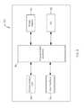
- FIG. 3shows a generalized block diagram of an exemplary implantable pulse generator (IPG) of the stimulator system of FIG. 1 .
- IPGimplantable pulse generator
- FIG. 4shows an exemplary kit for delivering the electrode lead of the stimulator system of FIG. 1 .
- FIG. 5shows a generalized block diagram of an exemplary circuitry housing that may be used together with the needle electrode of the kit of FIG. 4 .
- FIGS. 6A through 6Fshow an exemplary method for implanting the electrode lead of the stimulator system of FIG. 1 using the kit of FIG. 4 .
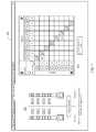
- FIG. 7is an exemplary screenshot illustrating various aspects of the graphical user interface of the software-based programming system of the present invention.
- the neuromuscular stimulation system of the present inventioncomprises implantable devices for facilitating electrical stimulation to tissue within a patient's back and external devices for wirelessly communicating programming data and stimulation commands to the implantable devices.
- the devices disclosed hereinmay be utilized to stimulate tissue associated with local segmental control of the lumbar spine in accordance with the programming data to rehabilitate the tissue over time.
- the stimulator systemmay be optimized for use in treating back pain in the region of the lumbar spine.
- the systems and methodsare expected to provide efficient implantation of the lead, including the ability to verify deployment of anchoring mechanisms on the lead, such that the implanted lead may be secured within the patient.
- Stimulator system 100may include electrode lead 200 , implantable pulse generator (IPG) 300 , activator 400 , optional magnet 450 , external programmer 500 , and software-based programming system 600 .
- IPGimplantable pulse generator
- Electrode lead 200includes lead body 202 having a plurality of electrodes, illustratively, electrodes 204 , 206 , 208 , and 210 . Electrode lead 200 is configured for implantation in or adjacent to tissue, e.g., nervous tissue, muscle, a ligament, and/or a joint capsule, including tissue associated with local segmental control of the lumbar spine. Electrode lead 200 is coupled to IPG 300 , for example, via connector block 302 . IPG 300 is configured to generate pulses such that electrodes 204 , 206 , 208 , and/or 210 deliver neuromuscular electrical stimulation (“NMES”) to target tissue.
- NMESneuromuscular electrical stimulation
- the electrodesare positioned to stimulate a peripheral nerve where the nerve enters skeletal muscle, which may be one or more of the multifidus, transverse abdominus, quadratus lumborum, psoas major, internus abdominus, obliquus externus abdominus, and erector spinae muscles.
- skeletal musclewhich may be one or more of the multifidus, transverse abdominus, quadratus lumborum, psoas major, internus abdominus, obliquus externus abdominus, and erector spinae muscles.
- Such stimulationmay induce contraction of the muscle to restore neural control and rehabilitate the muscle, thereby improving muscle function of local segmental muscles of the lumbar spine, improving lumbar spine stability, and reducing back pain.
- IPG 300may be controlled by, and optionally powered by, activator 400 , which includes control module 402 coupled to pad 404 , e.g., via cable 406 .
- Control module 402has user interface 408 that permits a user, e.g., patient, physician, caregiver, to adjust a limited number of operational parameters of IPG 300 including starting and stopping a treatment session.
- Control module 402communicates with IPG 300 via pad 404 , which may comprise an inductive coil or RF transceiver configured to communicate information in a bidirectional manner across a patient's skin to IPG 300 and, optionally, to transmit power to IPG 300 .
- a controller within control module 402may send a stimulation command(s) responsive to user input received at user interface 408 to a controller of IPG 300 via respective telemetry (or RF) systems in activator 400 and IPG 300 .
- the stimulation commandsmay include, for example, at least one of: a command to start a treatment session or stop the treatment session; a command to provide a status of IPG 300 ; or a request to conduct an impedance assessment.
- a limited number of stimulation parametersmay be adjusted at user interface 408 to minimize the chance of injury caused by adjustments made by non-physician users.
- the controller of activator 400also may send adjustments to stimulation parameters, e.g., pulse amplitude (voltage or current), pulse width, stimulation rate, stimulation frequency, ramp timing, cycle timing, session timing, and electrode configuration to IPG 300 responsive to user input received at user interface 408 .
- stimulation parameterse.g., pulse amplitude (voltage or current), pulse width, stimulation rate, stimulation frequency, ramp timing, cycle timing, session timing, and electrode configuration
- Stimulator system 100also may include optional magnet 450 configured to transmit a magnetic field across a patient's skin to IPG 300 such that a magnetic sensor of IPG 300 senses the magnetic field and IPG 300 starts or stops a treatment session responsive to the sensed magnetic field.
- optional magnet 450configured to transmit a magnetic field across a patient's skin to IPG 300 such that a magnetic sensor of IPG 300 senses the magnetic field and IPG 300 starts or stops a treatment session responsive to the sensed magnetic field.
- software-based programming system 600is installed and runs on a computer, e.g., conventional laptop, and is used by the patient's physician together with external programmer 500 to provide programming to IPG 300 .
- external programmer 500may be coupled, either wirelessly or using a cable such as cable 502 , to the physician's computer such that software-based programming system 600 may download for review data stored on IPG 300 via external programmer 500 .
- Software-based programming system 600also may transfer programming data to IPG 300 via external programmer 500 to reprogram stimulation parameters programmed into IPG 300 .
- programming system 600may be used to program and adjust parameters such as pulse amplitude (voltage or current), pulse width, stimulation rate, stimulation frequency, ramp timing, cycle timing, session timing, and electrode configuration.
- Programming system 600also may be configured to upload and store data retrieved from IPG 300 to a remote server for later access by the physician.
- Programming system 600may be configured to cause the computer to display an impedance measurement taken at electrode lead 200 and transmitted by IPG 300 . The impedance measurement may be used to determine whether the fixation element(s) on electrode lead 200 are in the delivered state or the deployed state, as described in detail below.
- Electrode lead 200contains a plurality of electrodes 204 , 206 , 208 , and 210 , disposed at distal end 211 of lead body 202 , that are configured to be implanted in or adjacent to tissue, such as nervous tissue, muscle, ligament, and/or joint capsule.
- Lead body 202is a suitable length for positioning the electrodes in or adjacent to target tissue while IPG is implanted in a suitable location, e.g., the lower back.
- lead body 202may be between about 30 and 80 cm in length, and preferably about 45 or about 65 cm in length.
- Electrodes 204 , 206 , 208 , and 210may be configured to stimulate the tissue at a stimulation frequency and at a level and duration sufficient to cause muscle to contract and may be ring electrodes, partial electrodes, segmented electrodes, nerve cuff electrodes placed around the nerve innervating the target muscle, or the like. Electrodes 204 , 206 , 208 , 210 are a suitable length(s) and spaced apart a suitable distance along lead body 202 .
- electrodes 204 , 206 , 208 , 210may be about 2-5 mm in length, and preferably about 3 mm, and may be spaced apart about 2-6 mm, and preferably about 4 mm.
- an electrode leadmay contain more or fewer than four electrodes.
- fixation elements 212 and 213may be coupled to lead body 202 via fixation ring 216 and fixation elements 214 and 215 may be coupled to lead body 202 via fixation ring 218 .
- Fixation elements 212 , 213 , 214 , 215are shown in a delivery state in FIG. 2A , wherein fixation elements 212 , 213 , 214 , 215 are positioned adjacent to electrode 210 , and are shown in a deployed state in FIG. 2B , wherein fixation elements 212 , 213 , 214 , 215 are spaced apart from electrode 210 and positioned to anchor lead 200 to an anchor site, e.g., muscle.
- Fixation elements 212 , 213 , 214 , 215are configured to collapse inward toward lead body 202 in the delivery state, shown in FIG. 2A , and may contact electrode 210 in the delivery state.
- the longitudinal axis of each fixation element 212 , 213 , 214 , 215when collapsed, is approximately parallel to the longitudinal axis of lead 200 at distal end 211 .
- fixation elements 212 , 213 , 214 , 215may be sized such that the outer surface of each fixation element 212 , 213 , 214 , 215 aligns with the outer surface of fixation rings 216 and 218 to minimize catching of fixation elements 212 , 213 , 214 , 215 when delivered through a sheath.
- fixation elements 212 , 213 , 214 , 215may at least partially cover portions of, or substantially all of, electrode 210 .
- the close proximity of fixation elements 212 , 213 , 214 , 215 to electrode 210 in the delivery statemay be utilized to determine whether fixation elements 212 , 213 , 214 , 215 have deployed during delivery because the impedance at electrode 210 is different when fixation elements 212 , 213 , 214 , 215 are deployed as compared to when fixation elements 212 , 213 , 214 , 215 are collapsed adjacent to electrode 210 .
- fixation elements 212 , 213 , 214 , 215are configured to self-expand, e.g., due to retraction of a sheath, in the deployed state.
- fixation elements 212 , 213 , 214 , 215are spaced apart from electrode 210 at an angle suitable for anchoring lead 200 to the anchor site.
- the angle between each fixation element 212 , 213 , 214 , 215 and the longitudinal axis of lead 200 at distal end 211is between about 10-90 degrees, 20-80 degrees, 25-70 degrees, 30-60 degrees, or 35-55 degrees, and preferably about 45 degrees.
- each fixation element 212 , 213 , 214 , 215 and the longitudinal axis of lead 200 at distal end 211need not be the same, and most likely will be different as each fixation element 212 , 213 , 214 , 215 expands individually through tissue.
- Fixation elements 212 and 214are configured to sandwich an anchor site, e.g., muscle, therebetween to secure electrode lead 200 at a target site without damaging the anchor site.
- fixation elements 213 and 215are configured to sandwich the same or a different anchor site therebetween to secure electrode lead 200 at the target site without damaging that anchor site.
- Fixation elements 212 and 213may be angled distally relative to lead body 202 , and resist motion in a first direction and prevent, in the case illustrated, insertion of the lead too far, as well as migration distally.
- Fixation element 212may be disposed opposite from fixation element 213 , as illustrated.
- Fixation elements 214 and 215are angled proximally relative to lead body 202 and penetrate through a tissue plane and deploy on the distal side of the tissue immediately adjacent to a target of stimulation. Fixation element 214 may be disposed opposite from fixation element 215 , as illustrated. As will be understood by one of skill in the art, an electrode lead may contain more or fewer than four fixation elements.
- Fixation elements 212 and 213are configured to resist motion in the opposite direction relative to fixation elements 214 and 215 . This combination prevents migration both proximally and distally, and also in rotation.
- fixation elements 212 and 213are coupled to lead body 202 between electrode 208 and distal most electrode 210 and fixation elements 214 and 215 are coupled to lead body 202 between distal most electrode 210 and end cap 220 .
- Fixation elements 212 , 213 , 214 , 215are preferably made from a nonconductive material, e.g., a nonconductive polymer, and have a generally rectangular cuboid shape, although the disclosure is not limited thereto and other shapes may be utilized such as curved shapes and hooks.
- the nonconductive materialmay be used to ensure that impedance at electrode lead 200 will be different between the delivery and the deployed states because the nonconductive material, when contacting or immediately adjacent to electrode 210 in the delivery state, will alter diffusion of energy to/from electrode 210 as compared to when the nonconductive material is spaced apart from electrode 210 in the deployed state.
- a measurement of the impedancemay be used to determine how many fixation elements 212 , 213 , 214 , 215 have deployed, as fixation elements 212 , 213 , 214 , 215 are independently deployable.
- an impedance measurement within a first rangee.g., between 1501-3500 ohms
- an impedance measurement within a second rangee.g., between 500-1500 ohms, different from the first range, may be indicative of fixation elements 212 , 213 , 214 , 215 being in the deployed state.
- an impedance measurement within a third rangemay be indicative of one of fixation elements 212 , 213 , 214 , 215 being in the deployed state while the remaining fixation elements are in the delivery state.
- an impedance measurement within a fourth rangee.g., 1000-2000 ohms, different from the first, second, and third ranges, may be indicative of two of fixation elements 212 , 213 , 214 , 215 being in the deployed state while the remaining fixation elements are in the delivery state.
- an impedance measurement within a fifth rangee.g., 750-1750 ohms, different from the first, second, third, and fourth ranges, may be indicative of three of fixation elements 212 , 213 , 214 , 215 being in the deployed state while the remaining fixation elements are in the delivery state.
- the length of and spacing between the fixation elementsis defined by the structure around which they are to be placed. In one embodiment, the length of each fixation element is between about 1.5-4 mm and preferably about 2.5 mm and the spacing is between about 2 mm and 10 mm and preferably about 6 mm.
- FIGS. 2A and 2Billustrate fixation elements 212 , 213 , 214 , 215 on lead body 202
- fixation elementsmay be used to anchor electrode lead 200 at a suitable location including the fixation elements described in U.S. Patent Application Pub. Nos. 2013/0131766 to Crosby and 2013/0338730 to Shiroff, both assigned to the assignee of the present invention, the entire contents of each of which is incorporated herein by reference.
- Lead body 202further may include stylet lumen 222 extending therethrough.
- Stylet lumen 222is shaped and sized to permit a stylet to be inserted therein, for example, during delivery of electrode lead 200 .
- end cap 220is used to prevent the stylet from extending distally out of stylet lumen 222 beyond end cap 220 .
- end cap 220may include a suitable coupling mechanism, e.g., threads, for coupling to the stylet such that the stylet is temporarily locked to end cap 220 .
- electrode lead 200includes contacts 226 , 228 , 230 , and 232 separated along lead body 202 by spacers 234 , 236 , 238 , 240 , and 242 .
- Contacts 226 , 228 , 230 , and 232may comprise an isodiametric terminal and are electrically coupled to electrodes 204 , 206 , 208 , and 210 , respectively, via, for example, individually coated spiral wound wires.
- a portion of proximal end 224is configured to be inserted in IPG 300 and set-screw retainer 244 is configured to receive a screw from IPG 300 to secure the portion of electrode lead 200 within IPG 300 .
- the electrode(s)may be an array of a plurality of electrodes, or may be a simple single electrode where the electrical circuit is completed with an electrode placed elsewhere (not shown) such as a skin surface patch or by the can of an implanted pulse generator.
- electrode lead 200may comprise a wirelessly activated or leadless electrode, such as described in U.S. Pat. No. 8,321,021 to Kisker, such that no lead need be coupled to IPG 300 .
- IPG 300is configured to cause the electrodes to stimulate in accordance with programming data stored in the memory of IPG 300 .
- IPG 300may include programmable controller 318 , communication unit 320 , power supply 324 , electrode switching array 326 , system sensors 328 , and optional therapeutic circuitry module 330 .
- Controller 318is electrically coupled to, and configured to control, the internal functional components of IPG 300 .
- Controller 318may comprise a commercially available microcontroller unit including a programmable microprocessor, volatile memory, nonvolatile memory such as EEPROM for storing programming, and nonvolatile storage, e.g., Flash memory, for storing firmware and a log of system operational parameters and patient data.
- the memory of controller 318stores program instructions that, when executed by the processor of controller 318 , cause the processor and the functional components of IPG 300 to provide the functionality ascribed to them herein.
- Controller 318is configured to be programmable such that programming data is stored in the memory of controller 318 and may be adjusted using external programmer 500 as described in detail in U.S. Patent Pub. No.
- Programming datamay include pulse amplitude (voltage or current), pulse width, stimulation rate, stimulation frequency, ramp timing, cycle timing, session timing, and electrode configuration.
- programmable parameters, their ranges, and nominal valuesare:
- Controller 318may be programmable to allow electrical stimulation between any chosen combination of electrodes on the lead, thus providing a simple bipolar configuration.
- controller 318may be programmed to deliver stimulation pulses in a guarded bipolar configuration (more than 1 anode surrounding a central cathode) or the housing of IPG 300 may be programmed as the anode, enabling unipolar stimulation from any of the electrodes.
- IPG 300may have two separate channels to facilitate bilateral stimulation and the electrode configuration, e.g., combination of positive and negative electrodes, may be programmed independently for each channel.
- IPG 300is illustratively implantable
- a pulse generatormay be disposed external to a body of a patient on a temporary or permanent basis without departing from the scope of the present invention.
- an external stimulatormay be coupled to the electrodes wirelessly.
- Controller 318further may be programmed with a routine to calculate the impedance at electrode lead 200 .
- controller 318may direct power supply 324 to send an electrical signal to one or more electrodes which emit electrical power.
- One or more other electrodesreceive the emitted electrical power and send a received signal to controller 318 that runs the routine to calculate impedance based on the sent signal and the received signal.
- the impedance measurementmay be used to determine whether one or more of the fixation elements coupled to the electrode lead body are in a delivery state or a deployed state.
- controller 318directs electrode 210 to emit energy such that electrode 204 , 206 , or 208 receives a portion of the emitted energy and sends a received signal to controller 318 .
- controller 318may direct electrode 204 , 206 , or 208 to emit energy such that electrode 210 receives a portion of the emitted energy and sends a received signal to controller 318 .
- Controller 318runs the routine to calculate impedance based on the signal having data indicative of emitted energy and the signal having data indicative of received energy to determine an impedance measurement.
- the proximity of the fixation element(s) to the electrode(s)will change the impedance measured at the electrode(s) as the resistance of the electrical energy traveling between electrodes increases as the angle between the fixation element(s) and the electrode(s) decreases.
- the resistance of electrical energy traveling between electrode 210 and electrode 204 , 206 , or 208may be higher in the delivery state than in the deployed state.
- Controller 318causes communication unit 320 to transmit a signal indicative of the impedance measurement to the external computer running software 600 , e.g., via external programmer 500 .
- a physicianmay review the impedance measurement on software 600 to determine whether one or more fixation elements are in the deployed or the delivery state. If the physician determines that one or more of the fixation elements are in the delivery state after retraction of a sheath, the physician may adjust the lead in an attempt to cause the non-deployed fixation element(s) to deploy. Then, the physician may request a second impedance measurement using software 600 .
- the external computertransmits the command, e.g., via external programmer 500 , to IPG 300 and controller 318 repeats the steps to calculate impedance.
- Controller 318then directs communication unit 320 to transmit a second signal indicative of the second impedance measurement to the external computer running software 600 , e.g., via external programmer 500 .
- the physicianmay determine whether one or more fixation elements have deployed based on the second impedance measurement. The physician may continue to adjust the lead and request impedance measurements as necessary until the physician is satisfied that the fixation elements have deployed.
- Controller 318is coupled to communication unit 320 having circuitry configured to communicate with activator 400 and the external computer, e.g., via external programmer 500 .
- Communication unit 320permits transmission of stimulation commands, and optionally power, between IPG 300 and activator 400 such that IPG 300 may be powered, programmed, and/or controlled by activator 400 .
- controller 318may start or stop a treatment session or to conduct an impedance assessment responsive to stimulation commands received from a corresponding communication unit (e.g., an inductive unit having a telemetry system and coil and/or a RF unit having a transceiver and antenna) of activator 400 .
- a corresponding communication unite.g., an inductive unit having a telemetry system and coil and/or a RF unit having a transceiver and antenna
- Communication unit 320further permits transmission of programming data, and optionally power, between IPG 300 and external programmer 500 such that IPG 300 may be powered, programmed, and/or controlled by software-based programming system 600 via external programmer 500 .
- controller 318may direct changes to at least one of pulse amplitude (voltage or current), pulse width, stimulation rate, stimulation frequency, ramp timing, cycle timing, session timing, and electrode configuration and to conduct an impedance assessment responsive to programming data received from a corresponding communication unit (e.g., an inductive unit having a telemetry system and coil and/or a RF unit having a transceiver and antenna) of external programmer 500 .
- a corresponding communication unite.g., an inductive unit having a telemetry system and coil and/or a RF unit having a transceiver and antenna
- Communication unit 320may include a telemetry system electrically coupled to an inductive coil.
- the technology for telemetry systems and coilsis well known to one skilled in the art and may include a magnet, a short range telemetry system, a longer range telemetry system (such as using MICS RF Telemetry available from Zarlink Semiconductor of Ottawa, Canada), or technology similar to a pacemaker programmer.
- the coilmay be used to transmit power only, and separate radio frequency transmitters may be provided in IPG 300 activator 400 , and/or external programmer 500 for establishing bidirectional or unidirectional data communication.
- Communication unit 320also may include (with or without the telemetry system and coil) a communications circuit employing a transceiver coupled to an antenna 334 (which may be inside or external to the hermetic housing).
- the transceiverpreferably comprises a radio frequency (RF) transceiver and is configured for bi-directional communications via the antenna with a similar transceiver circuit disposed in activator 400 and/or external programmer 500 .
- the transceivermay receive stimulation commands from activator 400 and programming data from software-based programming system 600 via external programmer 500 .
- Controller 318may direct changes to at least one of pulse amplitude (voltage or current), pulse width, stimulation rate, stimulation frequency, ramp timing, cycle timing, session timing, and electrode configuration, including commands to start or stop a treatment session or to conduct impedance assessment, responsive to programming data and/or stimulation commands received from a corresponding transceiver and antenna of activator 400 and/or external programmer 500 via the antenna and the transceiver of communication unit 320 .
- the transceiveralso may include a low power mode of operation, such that it periodically awakens to listen for incoming messages and responds only to those messages including the unique device identifier assigned to that IPG.
- the transceivermay employ an encryption routine to ensure that messages sent from, or received by, IPG 300 cannot be intercepted or forged.
- Communication unit 320may include a wireless chipset, e.g., WiFi, Bluetooth, cellular, thereby enabling IPG 300 to communicate wirelessly with activator 400 , external programmer 500 , and/or the external computer running software 600 .
- Power supply 324powers the electrical components of IPG 300 , and may comprise a primary cell or battery, a secondary (rechargeable) cell or battery or a combination of both. Alternatively, power supply 324 may not include a cell or battery, but instead comprise a capacitor that stores energy transmitted through the skin via a Transcutaneous Energy Transmission System (TETs), e.g., by inductive coupling. In a preferred embodiment, power supply 324 comprises a lithium ion battery.
- TETsTranscutaneous Energy Transmission System
- Controller 318further may be coupled to electrode switching array 326 so that any subset of electrodes of the electrode leads may be selectably coupled to therapeutic circuitry module 330 , described in detail below. In this way, an appropriate electrode set may be chosen from the entire selection of electrodes implanted in the patient's body to achieve a desired therapeutic effect. Electrode switching array 326 preferably operates at high speed, thereby allowing successive stimulation pulses to be applied to different electrode combinations.
- System sensors 328may comprise one or more sensors that monitor operation of the systems of IPG 300 , and log data relating to system operation as well as system faults, which may be stored in a log for later readout using software-based programming system 600 .
- system sensors 328include a magnetic sensor configured to sense a magnetic field and to transmit a signal to controller 318 based on the sensed magnetic field such that the controller starts or stops a treatment session.
- system sensors 328include one or more sensors configured to sense muscle contraction and to generate a sensor signal based on the muscle contraction.
- Controller 318is configured to receive the sensor signal from system sensors 328 and to adjust the stimulation parameters based on the sensor signal.
- system sensors 328sense an increase or decrease in muscle movement and controller 318 increases or decreases the stimulation frequency to maintain smooth and continuous muscle contraction.
- sensors 328may include an accelerometer that senses acceleration of a muscle caused by muscle contraction.
- the accelerometermay be a 1-, 2- or 3-axis analog or digital accelerometer that determines whether the patient is active or asleep or senses overall activity of the patient, which may be a surrogate measure for clinical parameters (e.g., more activity implies less pain), and/or a heart rate or breathing rate (minute ventilation) monitor, e.g., which may be obtained using one or more of the electrodes disposed on the electrode leads.
- the accelerometermay be used to determine the orientation of IPG 300 , and by inference the orientation of the patient, at any time.
- software-based programming system 600may be used to take a reading from the implant, e.g., when the patient is lying prone, to calibrate the orientation of the accelerometer. If the patient is instructed to lie prone during therapy delivery, then the accelerometer may be programmed to record the orientation of the patient during stimulation, thus providing information on patient compliance.
- system sensors 328may include a pressure sensor, a movement sensor, and/or a strain gauge configured to sense muscle contraction and to generate a sensor signal based on the muscle contraction, and in a further embodiment, various combinations of at least one of an accelerometer, a pressure sensor, a movement sensor, and/or a strain gauge are included.
- Sensors 328may also include, for example, a humidity sensor to measure moisture within housing 304 , which may provide information relating to the state of the electronic components, or a temperature sensor, e.g., for measuring battery temperature during charging to ensure safe operation of the battery. Data from the system sensors may be logged by controller 318 and stored in nonvolatile memory for later transmission to software-based programming system 600 via external programmer 500 .
- system sensors 328may be placed in a variety of locations including within housing 302 , within or adjacent to the tissue that is stimulated, and/or in proximity to the muscle to be contracted and connected via a separate lead to IPG 300 .
- sensors 324may be integrated into one or more of the leads used for stimulation or may be an independent sensor(s) operatively coupled to IPG 300 using, for example, radio frequency (RF) signals for transmitting and receiving data.
- RFradio frequency
- Controller 318also may be coupled to optional therapeutic circuitry module 330 that provides any of a number of complimentary therapeutic stimulation, analgesic, feedback or ablation treatment modalities as described in detail below.
- IPG 300illustratively includes one therapeutic circuitry module 330 , although additional circuitry modules may be employed in a particular embodiment depending upon its intended application, as described in U.S. Patent Application Publication No. 2011/0224665 to Crosby, assigned to the assignee of the present invention, the entire contents of which is incorporated herein by reference.
- Therapeutic circuitry module 330may be configured to provide different types of stimulation, either to induce muscle contractions or to block pain signals in afferent nerve fibers; to monitor muscle contractions induced by stimulation and adjust the applied stimulation regime as needed to obtain a desired result; or to selectively and intermittently ablate nerve fibers to control pain and thereby facilitate muscle rehabilitation.
- kit 700 for delivering electrode lead 200is described, including suture sleeve 701 , needle electrode 702 , and sheath 704 .
- components of the kitare not depicted to scale on either a relative or absolute basis.
- Suture sleeve 701illustratively includes first end section 706 , middle section 708 separated from first end section by first groove 710 , second end section 712 separated from middle section 708 by second groove 714 , and sleeve lumen 716 .
- First and second end sections 706 and 712may have truncated conical portions as shown.
- First and second grooves 710 and 714are sized and shaped to accept sutures such that suture sleeve 701 may be secured to tissue, e.g., superficial fascia, using the sutures.
- Sleeve lumen 716is sized such that electrode lead 200 may be inserted therethrough.
- Needle electrode 702may include distal tip 718 , radiopaque marker 720 , electrodes 722 , 724 disposed near distal tip 718 , and connector 726 .
- Distal tip 718 , radiopaque marker 720 , and electrodes 722 , 724are located at distal end 725 of needle electrode 702 .
- Distal tip 718is shaped with a needle point to facilitate insertion of needle electrode 702 through tissue to the target site. Alternatively, distal tip 718 may have a blunt end to minimize tissue damage during insertion and to separate anatomical structures along naturally occurring tissue planes.
- Radiopaque marker 720is configured to permit visualization of needle electrode 702 under fluoroscopic, acoustic, anatomic, or CT guidance during insertion.
- Electrodes 722 , 724are configured to emit energy to stimulate tissue.
- a needle electrodemay contain more or fewer than two electrodes and more than one radiopaque marker.
- Needle electrode 702may be coupled to processor housing 750 , e.g., via connector 726 .
- needle electrode 702may be coupled directly to an external computer such as the computer running software 600 , e.g., via connector 726 .
- Processor housing 750houses circuitry configured to cause electrodes 722 , 724 emit energy responsive to user input at the housing itself or at the computer running software 600 .
- Processor housing 750may be coupled to a computer, such as the computer running software 600 , via cable 728 and connector 730 .
- Sheath 704may include sheath lumen 732 , distal tip 734 , radiopaque marker 736 , windows 738 , 740 near distal tip 734 , coupling portion 742 , and handle 744 .
- Distal tip 734 , radiopaque marker 736 , and windows 738 , 740are located at distal end 741 of sheath 704 .
- Sheath lumen 732extends through sheath 704 and is shaped and sized to permit needle electrode 702 to slide therethrough.
- Distal tip 734is beveled to ease introduction through tissue.
- Radiopaque marker 736is configured to permit visualization of sheath 704 under fluoroscopic, acoustic, anatomic, or CT guidance during insertion.
- Windowsare configured to permit energy emitted from electrodes disposed within sheath 704 to travel therethrough while the electrodes remain within the sheath. Accordingly, the electrodes, e.g., electrodes on electrode lead 200 or needle electrode 702 , need not extend out the distal end of sheath 704 to stimulate tissue. Advantageously, proper positioning of the electrodes may be verified while the electrodes remain within sheath 704 minimizing the likelihood of needing to adjust electrode position after deployment, including deployment of a fixation element(s).
- Coupling portion 742illustratively a male end with threads, is configured to be coupled to a portion of needle electrode 702 .
- Handle 744is sized and shaped to permit a physician to comfortably hold sheath 704 . As will be understood by one of skill in the art, a sheath may contain more or fewer than two windows and more than one radiopaque marker.
- Processor housing 750may include programmable controller 752 , communication unit 754 , user interface 756 , power supply 758 , and input and output circuitry (I/O) 760 .
- programmable controller 752may include programmable controller 752 , communication unit 754 , user interface 756 , power supply 758 , and input and output circuitry (I/O) 760 .
- Controller 752is electrically coupled to, and configured to control, the internal functional components of processor housing 750 .
- Controller 752may comprise a commercially available microcontroller unit including a programmable microprocessor, volatile memory, nonvolatile memory such as EEPROM for storing programming, and nonvolatile storage, e.g., Flash memory, for storing firmware and a log of system operational parameters and patient data.
- the memory of controller 752may store program instructions that, when executed by the processor of controller 752 , cause the processor and the functional components of processor housing 750 to provide the functionality ascribed to them herein.
- Controller 752is configured to be programmable.
- controller 752may store and adjust stimulation parameters, e.g., pulse amplitude (voltage or current), pulse width, stimulation rate, stimulation frequency, ramp timing, cycle timing, session timing, and electrode configuration responsive to user input received at user interface 756 or at an external computer such as the computer running software 600 .
- stimulation parameterse.g., pulse amplitude (voltage or current), pulse width, stimulation rate, stimulation frequency, ramp timing, cycle timing, session timing, and electrode configuration responsive to user input received at user interface 756 or at an external computer such as the computer running software 600 .
- Controller 752may be coupled to communication unit 754 , which is configured to communicate with an external computer, such as the computer running software 600 .
- Communication unit 754may include a wireless chipset, e.g., WiFi, Bluetooth, cellular, thereby enabling processor housing 750 to communicate wirelessly with external programmer 500 and/or the external computer running software 600 .
- User interface 756is configured to receive user input and to display information to the user.
- User interface 756may include buttons, LEDs, a display, a touch screen, a keypad, a microphone, a speaker, a trackball, or the like for receiving user input and/or displaying information to the user.
- user interface 756may display current stimulation parameters and permit a user to adjust the stimulation parameters.
- User interface 756also may permit a user to cause one or more electrodes 722 , 724 to emit energy.
- Power supply 758powers the electrical components of processor housing 750 , and may comprise a primary cell or battery, a secondary (rechargeable) cell or battery or a combination of both. Alternatively, power supply 758 may be a port to allow processor housing 750 to be plugged into a conventional wall socket for powering components. Controller 752 may direct power supply 758 to send an electrical signal to one or more electrodes 722 , 724 which emit electrical energy at the stimulation parameters programmed in controller 752 .
- I/O 760may include ports for data communication such as wired communication with a computer and/or ports for receiving removable memory, e.g., SD card, upon which program instructions or data related to processor housing 750 use may be stored.
- I/O 760includes a port for connection to needle electrode 702 via connector 726 and another port for accepting cable 728 which may be connected to an external computer.
- needle electrode 702 and sheath 704are inserted transcutaneously and transmuscularly to a target site, e.g., in or adjacent to tissue associated with control of the lumbar spine.
- a target sitee.g., in or adjacent to tissue associated with control of the lumbar spine.
- distal end 725 of needle electrode 702is positioned in or adjacent to the tissue, as shown in FIG. 6A .
- tissuemay include nervous tissue, muscle, ligament, and/or joint capsule.
- muscleincludes skeletal muscle such as the multifidus, transverse abdominus, quadratus lumborum, psoas major, internus abdominus, obliquus externus abdominus, and erector spinae muscles and nervous tissue includes a peripheral nerve that innervates skeletal muscle.
- nervous tissuecomprises the dorsal ramus nerve, or fascicles thereof, that innervate the multifidus muscle.
- needle electrode 702is disposed within sheath lumen 732 prior to insertion such that needle electrode 702 and sheath 704 are inserted together.
- a guidewireneed not be delivered (i) prior to insertion of needle electrode 702 or sheath 704 , (ii) through needle electrode 702 or sheath 704 during insertion, or (iii) through needle electrode 702 or sheath 704 after insertion.
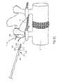
- FIGS. 6A-6Fdepict a lateral projection of a segment of a typical human lumbar spine shown having a vertebral body V, transverse process TP, inter-transverse ligament ITL, and a dorsal ramus DR.
- sheath 704 having needle electrode 702 disposed therethroughis positioned adjacent to the target site, illustratively, the medial branch of the dorsal ramus DR nerve that innervates the multifidus muscle.
- Distal tip 718 of needle electrode 702may extend out of the distal end of sheath 704 to facilitate insertion through tissue.
- electrodes of the electrode leadare positioned to stimulate the medial branch of the dorsal ramus that exits between the L2 and L3 lumbar segments and passes over the transverse process of the L3 vertebra, thereby eliciting contraction of fascicles of the lumbar multifidus at the L3, L4, L5 and 51 segments and in some patients also at the L2 segment.
- needle electrode 702stimulates the tissue.
- electrode 722 and/or electrode 724stimulates the tissue at the stimulation parameters defined at processor housing 750 .
- electrodes 722 , 724 of needle electrode 702emit energy through windows 738 , 740 while electrodes 722 , 724 remain within sheath 704 .
- windows 738 , 740are sized and spaced with the same or similar dimensions to the length and spacing of electrodes 722 , 724 of needle electrode 702 and/or electrodes 204 , 206 , 208 , 210 of electrode lead 200 . In this way, the electrodes are more likely to be aligned with the windows while disposed within the patient.
- radiopaque markers 720 , 736 of needle electrode 702 , sheath 704may be positioned such that electrodes 722 , 724 align within windows 738 , 740 , respectively, when radiopaque markers 720 , 736 are aligned.
- a radiopaque marker(s)may be disposed on electrode lead 200 to facilitate alignment of electrodes 204 , 206 , 208 , 210 within the windows of the sheath.
- one or more fixation elements 212 , 213 , 214 , 215has a radiopaque marker(s) to assist in visualization under fluoroscopic, acoustic, anatomic, or CT guidance to determine whether one or more of the fixation elements are in the delivery state or the deployed state.
- distal end 725 of needle electrode 702may be moved distally out of the distal end of sheath 704 while maintaining position of sheath 704 (or sheath 704 moved proximally, e.g., using handle 744 , while maintaining position of needle electrode 702 ), thereby exposing electrodes 722 , 724 , as shown in FIG. 6B .
- Such a stepmay be useful in embodiments where the sheath does not have windows.
- needle electrode 702stimulates the tissue.
- electrode 722 and/or electrode 724stimulates the tissue at the stimulation parameters defined at processor housing 750 .
- needle electrode 702 and sheath 704By stimulating the tissue, proper placement of needle electrode 702 and sheath 704 may be verified. For example, using fluoroscopy, acoustic, anatomic, or CT imaging, a physician may verify that the target muscle contracts responsive to the stimulation. If the target muscle does not contract, or does not contract in a suitable manner, the physician may adjust placement of needle electrode 702 and/or sheath 704 , e.g., by moving needle electrode 702 and/or sheath 704 proximally or distally. The physician may continue to make adjustments until suitable placement of needle electrode 702 and/or sheath 704 has been verified.
- needle electrode 702is removed from sheath 704 while maintaining position of sheath 704 at the target site.
- electrode lead 200is inserted through sheath lumen 732 of sheath 704 to position electrodes 204 , 206 , 208 , 210 at the target site, as shown in FIG. 6C .
- a radiopaque marker on electrode lead 200may be aligned with radiopaque marker 736 of sheath 704 to ensure that distal end 211 of electrode lead 200 is at distal end 741 of sheath 704 , and optionally, that the electrodes of electrode lead 200 are aligned within respective windows of sheath 704 .
- a guidewireneed not be delivered (i) prior to insertion of electrode lead 200 , (ii) through electrode lead 200 during insertion, or (iii) through electrode lead 200 after insertion.
- a styletmay be inserted within the stylet lumen of electrode lead 200 to provide additional stiffness to electrode lead 200 to ease passage of electrode lead 200 through sheath 704 .
- the styletmay be a commercially available stylet such as a locking stylet available from Cook Group Incorporated of Bloomington, Ind.
- electrode lead 200stimulates the tissue.
- electrode 204 , 206 , 208 and/or electrode 210stimulates the tissue at the stimulation parameters defined at a pulse generator, such as IPG 300 , coupled to the electrodes.
- a pulse generatorsuch as IPG 300
- electrodes 210 , 208 of electrode lead 200emit energy through windows 738 , 740 , respectively, while electrodes 210 , 208 remain within sheath 704 .
- a sheathmay contain more or fewer than two windows.
- sheath 704may have four windows sized and shaped to align with electrodes 204 , 206 , 208 , 210 of electrode lead.
- proper positioning of the electrodesmay be verified while the electrodes remain within sheath 704 minimizing the likelihood of needing to adjust electrode position after deployment, including deployment of a fixation element(s) on electrode lead 200 .
- distal end 211 of electrode lead 200may be moved distally out of the distal end of sheath 704 while maintaining position of sheath 704 (or sheath 704 moved proximally, e.g., using handle 744 , while maintaining position of electrode lead 200 ), thereby exposing one or more electrodes 204 , 206 , 208 , and/or 210 , as shown in FIGS. 6D and 6E .
- electrode lead 200stimulates the tissue.
- electrode 204 , 206 , 208 and/or electrode 210stimulates the tissue at the stimulation parameters defined at a pulse generator, such as IPG 300 , coupled to the electrodes.
- electrode lead 200By stimulating the tissue, proper placement of electrode lead 200 may be verified, and specifically placement of electrodes 204 , 206 , 208 , 210 at distal end 211 may be verified.
- a physicianmay verify that the target muscle contracts responsive to the stimulation. If the target muscle does not contract, or does not contract in a suitable manner, the physician may adjust placement of electrode lead 200 and/or sheath 704 , e.g., by moving electrode lead 200 and/or sheath 704 proximally or distally. The physician may continue to make adjustments until suitable placement of electrode lead 200 has been verified.
- fixation elements 212 , 213 , 214 , 215individually transition from a collapsed, delivery state within sheath 704 to an expanded, deployed state, shown in FIG. 6E , as the respective fixation element is exposed out of the distal end of sheath 704 .
- the fixation elementssandwich an anchor site, e.g., muscle, therebetween without damaging the anchor site in the expanded state to fix electrode lead 200 at the target site.
- one or more fixation elements 212 , 213 , 214 , 215may not expand to the deployed state, as shown in FIG. 6D .
- electrode lead 200stimulates the tissue.
- electrode 204 , 206 , 208 and/or electrode 210stimulates the tissue at the stimulation parameters responsive to a signal sent by a pulse generator, such as IPG 300 , coupled to the electrodes.
- a pulse generatorsuch as IPG 300
- One or more other electrodesreceive the emitted electrical power and send a received signal to the controller of the pulse generator that runs the routine to calculate impedance based on the sent signal and the received signal.
- the impedance measurementmay be used to determine whether one or more fixation elements 212 , 213 , 214 , 215 are in a delivery state or a deployed state.
- the pulse generatordirects electrode 210 to emit energy such that electrode 204 , 206 , or 208 receives a portion of the emitted energy and sends a received signal to the pulse generator. Also, the pulse generator may direct electrode 204 , 206 , or 208 to emit energy such that electrode 210 receives a portion of the emitted energy and sends a received signal to the pulse generator.
- the pulse generatorruns the routine to calculate impedance based on the signal having data indicative of emitted energy and the signal having data indicative of received energy to determine an impedance measurement.
- the proximity of the fixation element(s) to the electrode(s)will change the impedance measured at the electrode(s) as the resistance of the electrical energy traveling between electrodes increases as the angle between the fixation element(s) and the electrode(s) decreases.
- the resistance of electrical energy traveling between electrode 210 and electrode 204 , 206 , or 208may be higher in the delivery state than in the deployed state.
- the pulse generatortransmits a signal indicative of the impedance measurement to the external computer running software 600 , e.g., via external programmer 500 .
- a physicianmay review the impedance measurement on software 600 to determine whether one or more fixation elements 212 , 213 , 214 , 215 are in the deployed or the delivery state. If the physician determines that one or more fixation elements 212 , 213 , 214 , 215 are in the delivery state after retraction of a sheath (as is shown in FIG. 6D ), the physician may adjust electrode lead 200 in an attempt to cause the non-deployed fixation element(s) to deploy, e.g., move electrode lead 200 proximally and/or distally.
- the physicianmay request a second impedance measurement using software 600 .
- the external computertransmits the command, e.g., via external programmer 500 , to the pulse generator which repeats the steps to calculate impedance.
- the pulse generatorthen transmits a second signal indicative of the second impedance measurement to the external computer running software 600 , e.g., via external programmer 500 .
- the physicianmay determine whether one or more fixation elements 212 , 213 , 214 , 215 have deployed based on the second impedance measurement.
- the physicianmay continue to adjust electrode lead 200 and request impedance measurements as necessary until the physician is satisfied that fixation elements 212 , 213 , 214 , 215 have all deployed.
- software 600is configured to determine if the fixation element(s) is deployed and, preferably, how many fixation elements have deployed. For example, software 600 may process the impedance measurement to determine whether a fixation element(s) is deployed using a lookup table having stored impedance value ranges corresponding to the number of fixation elements deployed. Software 600 may cause the computer running software 600 to display a message reflecting the number of fixation elements deployed and/or reflecting suitable/unsuitable deployment of the fixation elements.
- sheath 704is moved proximally off the proximal end of electrode lead 200 and suture sleeve 701 is placed over the proximal end of electrode lead 200 and moved distally, as illustrated in FIG. 6F .
- suture sleeve 701is positioned adjacent to the superficial fascia SF beneath skin SK, sutures are sewn into the first and second grooves of suture sleeve 701 so as to secure suture sleeve 701 to the superficial fascia SF.
- the IPGis coupled to the proximal end of electrode lead 200 and implanted within the lower back of the patient.
- stimulation parametersare now described.
- such stimulation parametersare selected and programmed to induce contraction of muscle to restore neural control and rehabilitate muscle associated with control of the spine, thereby improving lumbar spine stability and reducing back pain.
- “to restore muscle function”means to restore an observable degree of muscle function as recognized by existing measures of patient assessment, such as the Oswestry Disability Index (“ODI”) as described in Lauridsen et al., Responsiveness and minimal clinically important difference for pain and disability instruments in low back pain patients , BMC Musculoskeletal Disorders, 7: 82-97 (2006), the European Quality of Life Assessment 5D (“EQ-5D”) as described in Brazier et al., A comparison of the EQ -5 D and SF -6 D across seven patient groups , Health Econ.
- OMIOswestry Disability Index
- EQ-5DEuropean Quality of Life Assessment 5D
- “to restore muscle function”means to observe at least a 15% improvement in one of the foregoing assessment scores within 30-60 days of initiation of treatment.
- the stimulation parametersmay be programmed into the IPG, may be adjusted in the IPG responsive to (i) stimulation commands transferred from the activator or (ii) programming data transferred from the external programmer.
- the stimulation parametersinclude, for example, pulse amplitude (voltage or current), pulse width, stimulation rate, stimulation frequency, ramp timing, cycle timing, session timing, and electrode configuration, including commands to start or stop a treatment session.
- pulse amplitudeis programmed to be adjustable between 0 and 7 mA.
- pulse amplitudeis programmed to be between about 2-5 mA, 2.5-4.5 mA, or 3-4 mA, and preferably about 3.5 mA.
- pulse widthis programmed to be adjustable between 25 and 500 ⁇ s.
- pulse widthis programmed to be between about 100-400 ⁇ s, 150-350 ⁇ s, or 200-300 ⁇ s, and preferably about 350 ⁇ s.
- stimulation rateis programmed to be adjustable between 1 and 40 Hz. In a preferred embodiment, stimulation rate is programmed to be between about 5-35 Hz, 10-30 Hz, or 15-20 Hz, and preferably about 20 Hz. In one embodiment, on ramp timing is programmed to be adjustable between 0 and 5 s. In a preferred embodiment, on ramp timing is programmed to be between about 0.5-4.5 s, 1-4 s, 1.5-3.5 s, or 2-3 s, and preferably about 2.5 s. In one embodiment, off ramp timing is programmed to be adjustable between 0 and 5 s.
- off ramp timingis programmed to be between about 0.5-4.5 s, 1-4 s, 1.5-3.5 s, or 2-3 s, and preferably about 2.5 s.
- cycle-on timingis programmed to be adjustable between 2 and 20 s.
- cycle-on timingis programmed to be between about 4-18 s, 6-16 s, 8-14 s, 9-13 s, or 10-12 s and preferably about 10 s.
- cycle-off timingis programmed to be adjustable between 20 and 120 s.
- cycle-off timingis programmed to be between about 30-110 s, 40-100 s, 50-90 s, 55-85 s, 60-80 s, or 65-75 s and preferably about 70 s.
- session timingis programmed to be adjustable between 1 and 60 min. In a preferred embodiment, session timing is programmed to be between about 5-55 min, 10-50 min, 15-45 min, 20-40 min, or 25-35 min, and preferably about 30 min.
- FIG. 7shows impedance screen 800 that is displayed to a physician running software-based programming system 600 .
- Impedance screen 800includes electrode configuration area 802 and impedance matrix area 804 .
- Electrode configuration area 802includes right electrode lead impedance display, left electrode lead impedance display, and Impedance area.
- Right electrode lead impedance displayshows an illustration of four electrodes (numbered 5-8) on the right electrode lead implanted within the subject while left electrode lead impedance display shows the four electrodes (numbered 1-4) on the left electrode lead implanted within the subject.
- a usermay select at which electrode(s) to measure impedance using the respective displays and may change the polarity of each electrode between positive and negative.
- negative electrode 6 on the right lead and negative electrode 2 on the left leadtransmit energy to target tissue to stimulate the tissue and positive electrodes 5 and 1, respectively, receive the energy after it has passed through the target tissue.
- Impedance areapermits a user to select the “Measure Impedance” button which causes the programming system, e.g., via the external programmer, to command the pulse generator to run the routine to measure impedances and then transmit the measured impedances back to the programming system, e.g., via the external programmer.
- the measured impedancesthen are displayed for each electrode. As described above, the displayed impedance may be used to determine whether one or more fixation elements on the electrode lead are deployed.
- Impedance matrix area 804includes an impedance matrix and a “Measure Impedance Matrix” button.
- the “Measure Impedance Matrix” buttonWhen pressed, the “Measure Impedance Matrix” button causes the impedance matrix to be populated with the measured impedances in accordance with selections made at electrode configuration area 802 .
- the impedance matrixis populated with the impedance measured between two select electrodes having opposite polarities during the impedance assessment, e.g., based on electrode activation and polarity selected at left electrode lead impedance display and right electrode lead impedance display.
- the displayed impedances in the impedance matrixmay be used to determine whether one or more fixation elements on the electrode lead are deployed.
- the impedance measurementsmay be time stamped. If an electrode shorts out, the IPG may be configured to exclude the nonfunctioning electrode and the time stamp may be used to determine when the electrode shorted out.
- impedance between electrode 2 (selected to be negative) and electrode 1 (selected to be positive) on the left leadis measured to be 490 Ohms and impedance between electrode 6 (selected to be negative) and electrode 5 (selected to be positive) on the right electrode lead is measured to be 1355 Ohms.
- the Measure Impedance Matrix buttonis pressed, the software causes 490 to be populated at the intersection of 2 negative and 1 positive and 1355 to be populated at the intersection of 6 negative and 5 positive in the impedance matrix.
- the impedance matrixalso may display when an electrode is excluded or out of range.
- a usermay enter data into the graphical user interface using suitable mechanisms known in the art, such as, entering numbers, letters, and/or symbols via a keyboard or touch screen, mouse, touchpad, selection from a drop-down menu, voice commands, or the like.
Landscapes
- Health & Medical Sciences (AREA)
- Life Sciences & Earth Sciences (AREA)
- General Health & Medical Sciences (AREA)
- Public Health (AREA)
- Animal Behavior & Ethology (AREA)
- Veterinary Medicine (AREA)
- Engineering & Computer Science (AREA)
- Biomedical Technology (AREA)
- Nuclear Medicine, Radiotherapy & Molecular Imaging (AREA)
- Radiology & Medical Imaging (AREA)
- Neurosurgery (AREA)
- Neurology (AREA)
- Heart & Thoracic Surgery (AREA)
- Cardiology (AREA)
- Orthopedic Medicine & Surgery (AREA)
- Surgery (AREA)
- Physical Education & Sports Medicine (AREA)
- Pain & Pain Management (AREA)
- Hospice & Palliative Care (AREA)
- Pathology (AREA)
- Medical Informatics (AREA)
- Molecular Biology (AREA)
- Oral & Maxillofacial Surgery (AREA)
- Electrotherapy Devices (AREA)
Abstract
Description
| Parameter | Min | Max | |||||
| Amplitude |
| 0 | mA | 7.0 | 1 | mA | |||
| Pulse Width | 25 | 500 | 200 | ||||
| Rate | |||||||
| 1 | Hz | 40 | Hz | 20 | Hz | ||
| On Ramp | 0 | s | 5 | s | 2 | s | |
| Off Ramp | |||||||
| Cycle-On | 2 | s | 20 | s | 10 | s | |
| Cycle-Off | 20 | s | 120 | s | 20 | s | |
| 1 | min | 60 | min | 30 | min | ||
Claims (14)
Priority Applications (7)
| Application Number | Priority Date | Filing Date | Title |
|---|---|---|---|
| US14/295,153US9186501B2 (en) | 2012-06-13 | 2014-06-03 | Systems and methods for implanting electrode leads for use with implantable neuromuscular electrical stimulator |
| CN201580029376.8ACN106456974B (en) | 2014-06-03 | 2015-05-27 | System for implanting electrode leads for use with implantable neuromuscular electrical stimulators |
| PCT/US2015/032732WO2015187426A1 (en) | 2014-06-03 | 2015-05-27 | Systems and methods for implanting electrode leads for use with implantable neuromuscular electrical stimulator |
| EP15727257.6AEP3151911B1 (en) | 2014-06-03 | 2015-05-27 | Systems for implanting electrode leads for use with implantable neuromuscular electrical stimulator |
| AU2015271098AAU2015271098B2 (en) | 2014-06-03 | 2015-05-27 | Systems and methods for implanting electrode leads for use with implantable neuromuscular electrical stimulator |
| CA2950905ACA2950905C (en) | 2014-06-03 | 2015-05-27 | Systems and methods for implanting electrode leads for use with implantable neuromuscular electrical stimulator |
| US14/939,955US9981122B2 (en) | 2012-06-13 | 2015-11-12 | Systems and methods for implanting electrode leads for use with implantable neuromuscular electrical stimulator |
Applications Claiming Priority (4)
| Application Number | Priority Date | Filing Date | Title |
|---|---|---|---|
| US201261659334P | 2012-06-13 | 2012-06-13 | |
| US13/797,100US9999763B2 (en) | 2012-06-13 | 2013-03-12 | Apparatus and methods for anchoring electrode leads adjacent to nervous tissue |
| US14/061,614US9072897B2 (en) | 2007-03-09 | 2013-10-23 | Systems and methods for restoring muscle function to the lumbar spine |
| US14/295,153US9186501B2 (en) | 2012-06-13 | 2014-06-03 | Systems and methods for implanting electrode leads for use with implantable neuromuscular electrical stimulator |
Related Parent Applications (1)
| Application Number | Title | Priority Date | Filing Date |
|---|---|---|---|
| US14/061,614Continuation-In-PartUS9072897B2 (en) | 2007-03-09 | 2013-10-23 | Systems and methods for restoring muscle function to the lumbar spine |
Related Child Applications (1)
| Application Number | Title | Priority Date | Filing Date |
|---|---|---|---|
| US14/939,955DivisionUS9981122B2 (en) | 2012-06-13 | 2015-11-12 | Systems and methods for implanting electrode leads for use with implantable neuromuscular electrical stimulator |
Publications (2)
| Publication Number | Publication Date |
|---|---|
| US20140288616A1 US20140288616A1 (en) | 2014-09-25 |
| US9186501B2true US9186501B2 (en) | 2015-11-17 |
Family
ID=51569686
Family Applications (2)
| Application Number | Title | Priority Date | Filing Date |
|---|---|---|---|
| US14/295,153ActiveUS9186501B2 (en) | 2012-06-13 | 2014-06-03 | Systems and methods for implanting electrode leads for use with implantable neuromuscular electrical stimulator |
| US14/939,955ActiveUS9981122B2 (en) | 2012-06-13 | 2015-11-12 | Systems and methods for implanting electrode leads for use with implantable neuromuscular electrical stimulator |
Family Applications After (1)
| Application Number | Title | Priority Date | Filing Date |
|---|---|---|---|
| US14/939,955ActiveUS9981122B2 (en) | 2012-06-13 | 2015-11-12 | Systems and methods for implanting electrode leads for use with implantable neuromuscular electrical stimulator |
Country Status (1)
| Country | Link |
|---|---|
| US (2) | US9186501B2 (en) |
Cited By (12)
| Publication number | Priority date | Publication date | Assignee | Title |
|---|---|---|---|---|
| US9474906B2 (en) | 2007-03-09 | 2016-10-25 | Mainstay Medical Limited | Systems and methods for restoring muscle function to the lumbar spine |
| WO2018007914A1 (en) | 2016-07-05 | 2018-01-11 | Mainstay Medical Limited | Systems and methods for enhanced implantation of electrode leads between tissue layers |
| WO2020069293A1 (en)* | 2018-09-28 | 2020-04-02 | Medtronic, Inc. | Impedance-based verification for delivery of implantable medical devices |
| US11331488B2 (en) | 2007-03-09 | 2022-05-17 | Mainstay Medical Limited | Systems and methods for enhancing function of spine stabilization muscles associated with a spine surgery intervention |
| US11331475B2 (en) | 2019-05-07 | 2022-05-17 | Medtronic, Inc. | Tether assemblies for medical device delivery systems |
| US11471670B2 (en) | 2010-03-11 | 2022-10-18 | Mainstay Medical Limited | Electrical stimulator for treatment of back pain and methods of use |
| US11679262B2 (en) | 2007-03-09 | 2023-06-20 | Mainstay Medical Limited | Systems and methods for restoring muscle function to the lumbar spine |
| US11679261B2 (en) | 2007-03-09 | 2023-06-20 | Mainstay Medical Limited | Systems and methods for enhancing function of spine stabilization muscles associated with a spine surgery intervention |
| US11684774B2 (en) | 2010-03-11 | 2023-06-27 | Mainstay Medical Limited | Electrical stimulator for treatment of back pain and methods of use |
| US11786725B2 (en) | 2012-06-13 | 2023-10-17 | Mainstay Medical Limited | Systems and methods for restoring muscle function to the lumbar spine and kits for implanting the same |
| US12097365B2 (en) | 2010-03-11 | 2024-09-24 | Mainstay Medical Limited | Electrical stimulator for the treatment of back pain and methods of use |
| US12151100B2 (en) | 2019-05-07 | 2024-11-26 | Medtronic, Inc. | Tether assemblies for medical device delivery systems |
Families Citing this family (31)
| Publication number | Priority date | Publication date | Assignee | Title |
|---|---|---|---|---|
| US10499937B2 (en) | 2006-05-19 | 2019-12-10 | Recor Medical, Inc. | Ablation device with optimized input power profile and method of using the same |
| US10925637B2 (en) | 2010-03-11 | 2021-02-23 | Mainstay Medical Limited | Methods of implanting electrode leads for use with implantable neuromuscular electrical stimulator |
| WO2008112178A1 (en) | 2007-03-09 | 2008-09-18 | Dan Sachs | Muscle stimulator |
| US11998266B2 (en) | 2009-10-12 | 2024-06-04 | Otsuka Medical Devices Co., Ltd | Intravascular energy delivery |
| KR101673574B1 (en) | 2009-10-30 | 2016-11-07 | 레코 메디컬, 인코포레이티드 | Method and apparatus for treatment of hypertension through percutaneous ultrasound renal denervation |
| US9999763B2 (en) | 2012-06-13 | 2018-06-19 | Mainstay Medical Limited | Apparatus and methods for anchoring electrode leads adjacent to nervous tissue |
| US9950159B2 (en) | 2013-10-23 | 2018-04-24 | Mainstay Medical Limited | Systems and methods for restoring muscle function to the lumbar spine and kits for implanting the same |
| US8788048B2 (en) | 2010-11-11 | 2014-07-22 | Spr Therapeutics, Llc | Systems and methods for the treatment of pain through neural fiber stimulation |
| US8788046B2 (en) | 2010-11-11 | 2014-07-22 | Spr Therapeutics, Llc | Systems and methods for the treatment of pain through neural fiber stimulation |
| US8788047B2 (en) | 2010-11-11 | 2014-07-22 | Spr Therapeutics, Llc | Systems and methods for the treatment of pain through neural fiber stimulation |
| US9186501B2 (en) | 2012-06-13 | 2015-11-17 | Mainstay Medical Limited | Systems and methods for implanting electrode leads for use with implantable neuromuscular electrical stimulator |
| US10195419B2 (en) | 2012-06-13 | 2019-02-05 | Mainstay Medical Limited | Electrode leads for use with implantable neuromuscular electrical stimulator |
| WO2014159276A1 (en) | 2013-03-14 | 2014-10-02 | Recor Medical, Inc. | Ultrasound-based neuromodulation system |
| US9999463B2 (en) | 2014-04-14 | 2018-06-19 | NeuroMedic, Inc. | Monitoring nerve activity |
| US12350050B2 (en) | 2014-04-14 | 2025-07-08 | Recor Medical, Inc. | Intraluminal microneurography probes and related systems and methods |
| US20170027460A1 (en) | 2015-07-29 | 2017-02-02 | NeuroMedic, Inc. | Intraluminal microneurography probe |
| EP3928829B1 (en) | 2014-10-13 | 2022-05-11 | Ecole Polytechnique Fédérale de Lausanne (EPFL) | Systems for treating sexual disorders using electro-stimulation |
| US10471268B2 (en) | 2014-10-16 | 2019-11-12 | Mainstay Medical Limited | Systems and methods for monitoring muscle rehabilitation |
| US10925579B2 (en) | 2014-11-05 | 2021-02-23 | Otsuka Medical Devices Co., Ltd. | Systems and methods for real-time tracking of a target tissue using imaging before and during therapy delivery |
| US11413450B2 (en) | 2015-10-15 | 2022-08-16 | Spr Therapeutics, Inc. | Apparatus and method for positioning, implanting and using a stimulation lead |
| AU2016340161B2 (en) | 2015-10-15 | 2021-07-15 | Spr Therapeutics, Inc. | Apparatus and method for positioning, implanting and using a stimulation lead |
| US11135437B2 (en) | 2015-10-15 | 2021-10-05 | Spr Therapeutics, Inc. | Apparatus and method for positioning, implanting and using a stimulation lead |
| EP4483943A3 (en)* | 2016-02-19 | 2025-03-12 | Nalu Medical, Inc. | Apparatus with enhanced stimulation waveforms |
| US9955882B2 (en) | 2016-08-31 | 2018-05-01 | Medtronic Xomed, Inc. | System to monitor neural integrity |
| US11540973B2 (en) | 2016-10-21 | 2023-01-03 | Spr Therapeutics, Llc | Method and system of mechanical nerve stimulation for pain relief |
| US10551282B2 (en)* | 2017-02-13 | 2020-02-04 | City University Of Hong Kong | Apparatus and method for testing performance of an electrosurgical tool |
| WO2018156953A1 (en) | 2017-02-24 | 2018-08-30 | Nalu Medical, Inc. | Apparatus with sequentially implanted stimulators |
| AU2018265016B2 (en) | 2017-05-09 | 2023-01-05 | Nalu Medical, Inc. | Stimulation apparatus |
| US20220111200A1 (en)* | 2020-10-12 | 2022-04-14 | Synerfuse, Inc. | Lead template and method of use at a spinal treatment site |
| US12419662B2 (en) | 2021-02-19 | 2025-09-23 | Otsuka Medical Devices Co., Ltd. | Selectively insulated ultrasound transducers |
| US12290680B2 (en)* | 2021-03-08 | 2025-05-06 | Spiro Medical, Inc. | Reversible anchor for spinal cord stimulator lead |
Citations (100)
| Publication number | Priority date | Publication date | Assignee | Title |
|---|---|---|---|---|
| US3077884A (en) | 1957-06-13 | 1963-02-19 | Batrow Lab Inc | Electro-physiotherapy apparatus |
| US3893463A (en) | 1973-12-07 | 1975-07-08 | Medtronic Inc | Dual channel stimulator |
| US4026301A (en) | 1975-04-21 | 1977-05-31 | Medtronic, Inc. | Apparatus and method for optimum electrode placement in the treatment of disease syndromes such as spinal curvature |
| US4342317A (en) | 1980-04-01 | 1982-08-03 | The Professional Staff Association Of The Rancho Los Amigos Hospital, Inc. | Method of electrical muscle stimulation for treatment of scoliosis and other spinal deformities |
| US4408609A (en) | 1980-04-01 | 1983-10-11 | Professional Staff Association Of The Rancho Los Amigos Hospital, Inc. | Electrical muscle stimulation for treatment of scoliosis and other spinal deformities |
| US4549556A (en) | 1982-12-08 | 1985-10-29 | Cordis Corporation | Implantable lead |
| US4658835A (en) | 1985-07-25 | 1987-04-21 | Cordis Corporation | Neural stimulating lead with fixation canopy formation |
| US4917093A (en) | 1987-06-12 | 1990-04-17 | Minnesota Mining And Manufacturing Company | Biological tissue stimulator with adjustable high voltage power supply dependent upon load impedance |
| US5215088A (en) | 1989-11-07 | 1993-06-01 | The University Of Utah | Three-dimensional electrode device |
| US5496345A (en) | 1992-06-02 | 1996-03-05 | General Surgical Innovations, Inc. | Expansible tunneling apparatus for creating an anatomic working space |
| US5501452A (en) | 1994-06-24 | 1996-03-26 | Halvorson; Glen A. | Putting training device using muscle memory |
| US5522854A (en) | 1994-05-19 | 1996-06-04 | Duke University | Method and apparatus for the prevention of arrhythmia by nerve stimulation |
| US5733307A (en) | 1996-09-17 | 1998-03-31 | Amei Technologies, Inc. | Bone anchor having a suture trough |
| US5741321A (en) | 1996-01-11 | 1998-04-21 | Medtronic, Inc. | Active fixation medical electrical lead having improved turning tool |
| US5916172A (en) | 1995-03-29 | 1999-06-29 | The University Of Queensland | Diagnosis of neuromuscular dysfunction |
| US5957968A (en) | 1997-09-26 | 1999-09-28 | Medtronic, Inc. | Suture sleeve with lead locking device |
| US6104957A (en) | 1998-08-21 | 2000-08-15 | Alo; Kenneth M. | Epidural nerve root stimulation with lead placement method |
| US6314325B1 (en) | 1998-04-07 | 2001-11-06 | William R. Fitz | Nerve hyperpolarization method and apparatus for pain relief |
| US6319241B1 (en) | 1998-04-30 | 2001-11-20 | Medtronic, Inc. | Techniques for positioning therapy delivery elements within a spinal cord or a brain |
| US6366819B1 (en) | 2000-10-03 | 2002-04-02 | Medtronic, Inc. | Biostable small French lead |
| US6406421B1 (en) | 1998-09-08 | 2002-06-18 | Medtronic, Inc. | System and method of determining skeletal muscle contraction by serial lead impedance measurements |
| US20020156513A1 (en) | 2000-08-17 | 2002-10-24 | Borkan William N. | Spinal cord stimulation leads |
| US6473654B1 (en) | 2000-03-08 | 2002-10-29 | Advanced Bionics Corporation | Lead anchor |
| US6516227B1 (en) | 1999-07-27 | 2003-02-04 | Advanced Bionics Corporation | Rechargeable spinal cord stimulator system |
| US6527787B1 (en) | 1995-05-19 | 2003-03-04 | General Surgical Innovations, Inc. | Methods and devices for blood vessel harvesting |
| US20030120328A1 (en)* | 2001-12-21 | 2003-06-26 | Transneuronix, Inc. | Medical implant device for electrostimulation using discrete micro-electrodes |
| US6600956B2 (en) | 2001-08-21 | 2003-07-29 | Cyberonics, Inc. | Circumneural electrode assembly |
| US20030199938A1 (en)* | 2002-04-22 | 2003-10-23 | Karel Smits | Precise cardiac lead placement based on impedance measurements |
| US6671557B1 (en) | 2000-10-10 | 2003-12-30 | Meagan Medical, Inc. | System and method for providing percutaneous electrical therapy |
| US6735474B1 (en) | 1998-07-06 | 2004-05-11 | Advanced Bionics Corporation | Implantable stimulator system and method for treatment of incontinence and pain |
| US20040111118A1 (en) | 2000-09-26 | 2004-06-10 | Hill Michael R.S. | Method and system for spinal cord stimulation prior to and during a medical procedure |
| US20040122482A1 (en) | 2002-12-20 | 2004-06-24 | James Tung | Nerve proximity method and device |
| US20040236383A1 (en) | 2003-05-23 | 2004-11-25 | Yelizarov Nikolay I. | MONES for muscle strain, repetitive strain injuries and related health conditions |
| US6839594B2 (en) | 2001-04-26 | 2005-01-04 | Biocontrol Medical Ltd | Actuation and control of limbs through motor nerve stimulation |
| US20050080472A1 (en) | 2003-10-10 | 2005-04-14 | Atkinson Robert Emmett | Lead stabilization devices and methods |
| US20050154389A1 (en) | 2003-12-16 | 2005-07-14 | Depuy Spine, Inc. | Methods and devices for minimally invasive spinal fixation element placement |
| US20060009827A1 (en) | 2002-11-15 | 2006-01-12 | Kurth Paul A | Method and apparatus for anchoring of pacing leads |
| US20060106416A1 (en) | 2004-10-29 | 2006-05-18 | Douglas Raymond | Expandable ports and methods for minimally invasive surgery |
| US20060111746A1 (en) | 2001-04-20 | 2006-05-25 | Foreman Robert D | Cardiac neuromodulation and methods of using same |
| US20060111754A1 (en) | 2000-01-20 | 2006-05-25 | Ali Rezai | Methods of treating medical conditions by neuromodulation of the sympathetic nervous system |
| US20060184222A1 (en) | 2000-01-20 | 2006-08-17 | Medtronic, Inc. | Medical electrical lead with interchangeable fixation member |
| US7096070B1 (en) | 2000-02-09 | 2006-08-22 | Transneuronix, Inc. | Medical implant device for electrostimulation using discrete micro-electrodes |
| US20060235484A1 (en) | 2005-03-14 | 2006-10-19 | Jaax Kristen N | Stimulation of a stimulation site within the neck or head |
| US20060241716A1 (en) | 2002-12-13 | 2006-10-26 | Finch Philip M | System and method for electrical stimulation of the intervertebral disc |
| WO2006133445A2 (en) | 2005-06-09 | 2006-12-14 | Medtronic, Inc. | Implantable medical lead |
| WO2006135791A2 (en) | 2005-06-09 | 2006-12-21 | Medtronic, Inc. | Peripheral nerve field stimulation and spinal cord stimulation |
| US20070027501A1 (en) | 2005-07-29 | 2007-02-01 | Medtronic, Inc. | Multi-application trial stimulator |
| US7206641B2 (en) | 2003-07-23 | 2007-04-17 | University Hospitals Of Cleveland | Mapping probe system for neuromuscular electrical stimulation apparatus |
| US20070100411A1 (en) | 2005-10-27 | 2007-05-03 | Medtronic, Inc. | Implantable medical electrical stimulation lead fixation method and apparatus |
| US20070100408A1 (en) | 2005-10-28 | 2007-05-03 | Medtronic, Inc. | Electrical stimulation lead with proximal common electrode |
| US20070100377A1 (en) | 2005-10-28 | 2007-05-03 | Cyberonics, Inc. | Providing multiple signal modes for a medical device |
| US20070100391A1 (en) | 2005-10-27 | 2007-05-03 | Cyberonics, Inc. | Sequenced therapy protocols for an implantable medical device |
| US20070135768A1 (en) | 2005-12-14 | 2007-06-14 | Carlsen Wayne D | Spinal and epidural regional anesthesia catheter |
| US7239918B2 (en) | 2004-06-10 | 2007-07-03 | Ndi Medical Inc. | Implantable pulse generator for providing functional and/or therapeutic stimulation of muscles and/or nerves and/or central nervous system tissue |
| US7286879B2 (en) | 2004-07-16 | 2007-10-23 | Boston Scientific Scimed, Inc. | Method of stimulating fastigium nucleus to treat neurological disorders |
| EP1255583B1 (en) | 2000-02-09 | 2007-12-19 | Medtronic Transneuronix, Inc. | Medical implant device for electrostimulation using discrete micro-electrodes |
| US7317948B1 (en) | 2002-02-12 | 2008-01-08 | Boston Scientific Scimed, Inc. | Neural stimulation system providing auto adjustment of stimulus output as a function of sensed impedance |
| US7324853B2 (en) | 2001-04-26 | 2008-01-29 | Biocontrol Medical Ltd. | Nerve stimulation for treating spasticity, tremor, muscle weakness, and other motor disorders |
| US7324852B2 (en) | 2004-02-25 | 2008-01-29 | Giancarlo Barolat | System and method for neurological stimulation of peripheral nerves to treat low back pain |
| US7337005B2 (en) | 2004-09-08 | 2008-02-26 | Spinal Modulations, Inc. | Methods for stimulating a nerve root ganglion |
| WO2008048471A2 (en) | 2006-10-13 | 2008-04-24 | Apnex Medical, Inc. | Obstructive sleep apnea treatment devices, systems and methods |
| US20080103573A1 (en) | 2006-10-31 | 2008-05-01 | Medtronic, Inc. | Implantable medical elongated member including wire-like fixation elements |
| US20080103579A1 (en) | 2006-10-31 | 2008-05-01 | Medtronic, Inc. | Implantable medical elongated member with adhesive elements |
| US20080132961A1 (en) | 2006-11-30 | 2008-06-05 | Advanced Bionics Corporation | Implant tool for use with a microstimulator |
| US20080183257A1 (en) | 2007-01-29 | 2008-07-31 | Spinal Modulation, Inc. | Sutureless lead retention features |
| US20080183221A1 (en) | 2006-12-06 | 2008-07-31 | Spinal Modulation, Inc. | Hard tissue anchors and delivery devices |
| US20080228241A1 (en) | 2007-03-09 | 2008-09-18 | Dan Sachs | Muscle stimulator |
| US7444181B2 (en) | 2005-12-14 | 2008-10-28 | Boston Scientific Neuromodulation Corporation | Techniques for sensing and adjusting a compliance voltage in an implantable stimulator device |
| US7489561B2 (en) | 2005-10-24 | 2009-02-10 | Cyberonics, Inc. | Implantable medical device with reconfigurable non-volatile program |
| US7493175B2 (en) | 2003-04-11 | 2009-02-17 | Cardiac Pacemakers, Inc. | Subcutaneous lead with tined fixation |
| US20090112263A1 (en) | 2007-10-30 | 2009-04-30 | Scott Pool | Skeletal manipulation system |
| US20090259280A1 (en) | 2007-10-15 | 2009-10-15 | Kevin Wilkin | Electrical stimulation lead with bioerodible anchors and anchor straps |
| WO2009134475A1 (en) | 2008-04-29 | 2009-11-05 | Medtronic, Inc. | Therapy program modification based on a therapy field model |
| US20100030227A1 (en) | 2008-07-31 | 2010-02-04 | Medtronic, Inc. | Medical lead implantation |
| US20100036454A1 (en) | 1998-06-03 | 2010-02-11 | Ndi Medical, Llc. | Systems and methods to place one or more leads in muscle for providing electrical stimulation to treat pain |
| US7668598B2 (en) | 2006-05-18 | 2010-02-23 | Uroplasty, Inc. | Method and apparatus for stimulating a nerve of a patient |
| US7684866B2 (en) | 2003-08-01 | 2010-03-23 | Advanced Neuromodulation Systems, Inc. | Apparatus and methods for applying neural stimulation to a patient |
| US20100082086A1 (en) | 2008-09-28 | 2010-04-01 | Jie Zhu | Expandable neuromodular stimulation lead |
| US20100174240A1 (en) | 2009-01-06 | 2010-07-08 | Medtronic, Inc. | Anchor having fill port for use with an implantable therapy delivery element |
| US7908015B2 (en) | 2008-07-31 | 2011-03-15 | Medtronic, Inc. | Subcutaneously implantable lead including distal fixation mechanism |
| US7917230B2 (en) | 2007-01-30 | 2011-03-29 | Cardiac Pacemakers, Inc. | Neurostimulating lead having a stent-like anchor |
| US7930039B2 (en) | 2005-01-07 | 2011-04-19 | Medtronic, Inc. | Implantable retention system and method |
| US20110224682A1 (en) | 2010-03-11 | 2011-09-15 | Westlund Randy W | Methods of implanting electrode leads for use with implantable neuromuscular electrical stimulator |
| US20110224665A1 (en) | 2010-03-11 | 2011-09-15 | Peter Andrew Crosby | Modular stimulator for treatment of back pain, implantable rf ablation system and methods of use |
| US20110251662A1 (en)* | 2010-04-13 | 2011-10-13 | Medtronic Vascular, Inc. | Slidable Fixation Device for Securing a Medical Implant |
| US20110270340A1 (en)* | 2010-04-30 | 2011-11-03 | Medtronic Vascular,Inc. | Two-Stage Delivery Systems and Methods for Fixing a Leadless Implant to Tissue |
| US20120035953A1 (en) | 2007-01-22 | 2012-02-09 | Cyberonics, Inc. | Method and Apparatus for Integrating Implantable Medical Device Data |
| US8170690B2 (en) | 2009-02-13 | 2012-05-01 | Pacesetter, Inc. | Implantable medical lead having an anchor providing enhanced fixation |
| WO2012057916A1 (en) | 2010-10-29 | 2012-05-03 | Medtronic Ablation Frontiers Llc | Catheter with coronary sinus ostium anchor |
| US20120116477A1 (en) | 2009-07-10 | 2012-05-10 | Bio-Medical Research Ltd. | Method and apparatus for stimulating the lower back and abdominal muscles |
| WO2012091747A1 (en) | 2010-12-29 | 2012-07-05 | Medtronic, Inc. | Implantable medical device fixation testing |
| US8229656B2 (en) | 2008-07-23 | 2012-07-24 | Omron Corporation | Engine starting device |
| US8249701B2 (en) | 2008-10-15 | 2012-08-21 | Spinal Modulation, Inc. | Methods, devices and systems for programming neurostimulation |
| US20120283800A1 (en) | 2011-01-28 | 2012-11-08 | Stimwave Technologies Incorporated | Neural Stimulator System |
| US20120323253A1 (en)* | 2010-09-28 | 2012-12-20 | Ellis Garai | Device and method for positioning an electrode in tissue |
| US20130023974A1 (en) | 2011-07-22 | 2013-01-24 | Jacob Amrani | Implantable lead with tethers |
| US8380318B2 (en) | 2009-03-24 | 2013-02-19 | Spinal Modulation, Inc. | Pain management with stimulation subthreshold to paresthesia |
| US20130131766A1 (en) | 2011-08-02 | 2013-05-23 | Peter Andrew Crosby | Apparatus and methods for anchoring electrode leads for use with implantable neuromuscular electrical stimulator |
| US20140046398A1 (en) | 2007-03-09 | 2014-02-13 | Mainstay Medical Limited | Systems and methods for restoring muscle function to the lumbar spine |
| US20140058476A1 (en) | 2011-12-19 | 2014-02-27 | Mainstay Medical Limited | Apparatus and methods for rehabilitating a muscle and assessing progress of rehabilitation |
Family Cites Families (139)
| Publication number | Priority date | Publication date | Assignee | Title |
|---|---|---|---|---|
| US3710777A (en) | 1970-12-23 | 1973-01-16 | C Sparks | Method and apparatus for growing graft tubes in place |
| US3875947A (en) | 1974-02-19 | 1975-04-08 | James L Jula | Device for screwing body tissue electrode into body tissue |
| US4010757A (en) | 1974-02-19 | 1977-03-08 | Jula James L | Auxiliary tool for removing electrode from holder |
| US3999551A (en) | 1975-01-07 | 1976-12-28 | Bio-Medical Research, Ltd. | Subcutaneous guide assembly |
| US4418693A (en) | 1980-12-10 | 1983-12-06 | Leveen Eric G | Vein and tubing passer surgical instrument |
| US4574806A (en) | 1984-10-01 | 1986-03-11 | Cordis Corporation | Tunnelling device for peripheral vascular reconstruction |
| US4832687A (en) | 1987-12-31 | 1989-05-23 | Smith Iii Ray C | Subcutaneous tunneling instrument and method |
| US5069680A (en) | 1989-12-06 | 1991-12-03 | Medtronic, Inc. | Muscle stimulator with variable duty cycle |
| US5199430A (en) | 1991-03-11 | 1993-04-06 | Case Western Reserve University | Micturitional assist device |
| US5330515A (en) | 1992-06-17 | 1994-07-19 | Cyberonics, Inc. | Treatment of pain by vagal afferent stimulation |
| US5324323A (en) | 1992-09-09 | 1994-06-28 | Telectronics Pacing Systems, Inc. | Multiple channel cardiosynchronous myoplasty apparatus |
| US5273053A (en) | 1992-11-02 | 1993-12-28 | Medtronic, Inc. | Suture sleeve with lead locking device |
| US5300108A (en) | 1993-01-05 | 1994-04-05 | Telectronics Pacing Systems, Inc. | Active fixation lead with a dual-pitch, free spinning compound screw |
| US5782841A (en) | 1993-08-10 | 1998-07-21 | Medtronic, Inc. | Tunneling tool for subcutaneous lead placement |
| JP2596372B2 (en) | 1994-04-21 | 1997-04-02 | 日本電気株式会社 | Evoked potential measurement device |
| US5569183A (en) | 1994-06-01 | 1996-10-29 | Archimedes Surgical, Inc. | Method for performing surgery around a viewing space in the interior of the body |
| US5507788A (en) | 1994-08-11 | 1996-04-16 | The Regents Of The University Of California | Method and apparatus for controlling skeletal muscle fatigue during electrical stimulation |
| US5653739A (en) | 1995-09-13 | 1997-08-05 | Empi, Inc. | Electronic pain feedback system and method |
| US6119516A (en) | 1997-05-23 | 2000-09-19 | Advantedge Systems, Inc. | Biofeedback system for monitoring the motion of body joint |
| US5807234A (en) | 1997-06-27 | 1998-09-15 | Pacesetter, Inc. | Myostimulator control using metabolic demand and muscle performance |
| US6565594B1 (en) | 1997-09-24 | 2003-05-20 | Atrium Medical Corporation | Tunneling device |
| US6113609A (en) | 1998-05-26 | 2000-09-05 | Scimed Life Systems, Inc. | Implantable tissue fastener and system for treating gastroesophageal reflux disease |
| US6845271B2 (en) | 1998-06-03 | 2005-01-18 | Neurocontrol Corporation | Treatment of shoulder dysfunction using a percutaneous intramuscular stimulation system |
| NZ501422A (en) | 1998-06-03 | 2003-01-31 | Neurocontrol Corp | Intramuscular stimulation system comprising a plurality of implantable electrodes in combination with a portable device equipped with a memorised set of movements for eliciting a series of muscle responses to prevent muscle atrophy |
| US6324414B1 (en) | 1999-05-18 | 2001-11-27 | Depuy Orthopaedics, Inc. | Tunneling lead terminal having a disposal sheath |
| US6505075B1 (en) | 1999-05-29 | 2003-01-07 | Richard L. Weiner | Peripheral nerve stimulation method |
| US8409233B1 (en) | 1999-11-19 | 2013-04-02 | Boston Scientific Neuromodulation | Combined subcutaneous tunneler and carrier |
| US6605094B1 (en) | 1999-11-19 | 2003-08-12 | Advanced Bionics Corporation | Integrated subcutaneous tunneling and carrying tool |
| US7483743B2 (en) | 2000-01-11 | 2009-01-27 | Cedars-Sinai Medical Center | System for detecting, diagnosing, and treating cardiovascular disease |
| US7024247B2 (en) | 2001-10-15 | 2006-04-04 | Northstar Neuroscience, Inc. | Systems and methods for reducing the likelihood of inducing collateral neural activity during neural stimulation threshold test procedures |
| US6871099B1 (en) | 2000-08-18 | 2005-03-22 | Advanced Bionics Corporation | Fully implantable microstimulator for spinal cord stimulation as a therapy for chronic pain |
| US6862479B1 (en) | 2000-08-30 | 2005-03-01 | Advanced Bionics Corporation | Spinal cord stimulation as a therapy for sexual dysfunction |
| US6432037B1 (en) | 2000-08-31 | 2002-08-13 | Flexiprobe Ltd. | Intravaginal device for electrically stimulating and/or for sensing electrical activity of muscles and/or nerves defining and surrounding the intravaginal cavity |
| US6847849B2 (en)* | 2000-11-15 | 2005-01-25 | Medtronic, Inc. | Minimally invasive apparatus for implanting a sacral stimulation lead |
| US6611710B2 (en) | 2000-11-29 | 2003-08-26 | Pacesetter, Inc. | Double threaded stylet for extraction of leads with a threaded electrode |
| US7065408B2 (en) | 2001-01-11 | 2006-06-20 | Herman Richard M | Method for restoring gait in individuals with chronic spinal cord injury |
| US6600954B2 (en) | 2001-01-25 | 2003-07-29 | Biocontrol Medical Bcm Ltd. | Method and apparatus for selective control of nerve fibers |
| US8882755B2 (en) | 2002-03-05 | 2014-11-11 | Kimberly-Clark Inc. | Electrosurgical device for treatment of tissue |
| US7018384B2 (en) | 2002-08-29 | 2006-03-28 | Medtronic, Inc. | Medical passing device and method |
| US7369894B2 (en) | 2002-09-06 | 2008-05-06 | Medtronic, Inc. | Method, system and device for treating disorders of the pelvic floor by electrical stimulation of the sacral and/or pudendal nerves |
| US8613744B2 (en) | 2002-09-30 | 2013-12-24 | Relievant Medsystems, Inc. | Systems and methods for navigating an instrument through bone |
| WO2004060146A2 (en) | 2002-12-30 | 2004-07-22 | Purdue Research Foundation | Method of treatment for central nervous system injury |
| US7349742B2 (en) | 2003-04-11 | 2008-03-25 | Cardiac Pacemakers, Inc. | Expandable fixation elements for subcutaneous electrodes |
| US7218970B2 (en) | 2003-06-20 | 2007-05-15 | Cardiac Pacemakers, Inc. | System for medical lead tunneling |
| US7359755B2 (en)* | 2003-08-08 | 2008-04-15 | Advanced Neuromodulation Systems, Inc. | Method and apparatus for implanting an electrical stimulation lead using a flexible introducer |
| US7343202B2 (en)* | 2004-02-12 | 2008-03-11 | Ndi Medical, Llc. | Method for affecting urinary function with electrode implantation in adipose tissue |
| US7418292B2 (en) | 2003-10-01 | 2008-08-26 | Medtronic, Inc. | Device and method for attenuating an immune response |
| US8112159B2 (en)* | 2003-10-03 | 2012-02-07 | Medtronic, Inc. | Kit for implantation of therapy elements |
| EP1711222A4 (en) | 2003-12-19 | 2011-02-09 | Savacor Inc | Digital electrode for cardiac rhythm management |
| US7295881B2 (en) | 2003-12-29 | 2007-11-13 | Biocontrol Medical Ltd. | Nerve-branch-specific action-potential activation, inhibition, and monitoring |
| US7499746B2 (en) | 2004-01-30 | 2009-03-03 | Encore Medical Asset Corporation | Automated adaptive muscle stimulation method and apparatus |
| US8467875B2 (en)* | 2004-02-12 | 2013-06-18 | Medtronic, Inc. | Stimulation of dorsal genital nerves to treat urologic dysfunctions |
| US20080132969A1 (en)* | 2004-02-12 | 2008-06-05 | Ndi Medical, Inc. | Systems and methods for bilateral stimulation of left and right branches of the dorsal genital nerves to treat urologic dysfunctions |
| US8182792B2 (en) | 2004-03-23 | 2012-05-22 | Novartis Ag | Pharmaceutical compositions |
| GB0409769D0 (en) | 2004-04-30 | 2004-06-09 | Algotec Ltd | Electrical nerve stimulation device |
| CA2566614A1 (en) | 2004-06-10 | 2005-12-29 | Ndi Medical, Llc | Systems and methods for bilateral stimulation of left and right branches of the dorsal genital nerves to treat dysfunctions, such as urinary incontinence |
| WO2006012050A2 (en) | 2004-06-30 | 2006-02-02 | Cvrx, Inc. | Connection structures for extra-vascular electrode lead body |
| US7238883B2 (en) | 2004-08-11 | 2007-07-03 | Cardiac Pacemakers, Inc. | Lead assembly with flexible portions and method therefor |
| US8219189B2 (en) | 2004-12-01 | 2012-07-10 | Penny Knoblich | Method and apparatus for improving renal function |
| US8066702B2 (en)* | 2005-01-11 | 2011-11-29 | Rittman Iii William J | Combination electrical stimulating and infusion medical device and method |
| US8260426B2 (en) | 2008-01-25 | 2012-09-04 | Cyberonics, Inc. | Method, apparatus and system for bipolar charge utilization during stimulation by an implantable medical device |
| US20060259074A1 (en) | 2005-02-22 | 2006-11-16 | Brian Kelleher | Methods and devices for anchoring to soft tissue |
| US8774912B2 (en) | 2005-02-23 | 2014-07-08 | Medtronic, Inc. | Implantable neurostimulator supporting trial and chronic modes |
| WO2006135753A1 (en) | 2005-06-09 | 2006-12-21 | Medtronic, Inc. | Introducer for therapy delivery elements |
| US7890166B2 (en) | 2005-06-09 | 2011-02-15 | Medtronic, Inc. | Regional therapies for treatment of pain |
| US20070049980A1 (en) | 2005-08-30 | 2007-03-01 | Zielinski Todd M | Trans-septal pressure sensor |
| US8016846B2 (en) | 2005-10-27 | 2011-09-13 | Medtronic Xomed, Inc. | Micro-resecting and evoked potential monitoring system and method |
| US7596414B2 (en) | 2005-12-05 | 2009-09-29 | Boston Scientific Neuromodulation Corporation | Cuff electrode arrangement for nerve stimulation and methods of treating disorders |
| US7801601B2 (en) | 2006-01-27 | 2010-09-21 | Cyberonics, Inc. | Controlling neuromodulation using stimulus modalities |
| US20070208392A1 (en) | 2006-02-17 | 2007-09-06 | Alfred E. Mann Foundation For Scientific Research | System for functional electrical stimulation |
| US7715920B2 (en) | 2006-04-28 | 2010-05-11 | Medtronic, Inc. | Tree-based electrical stimulator programming |
| US7761166B2 (en) | 2006-04-28 | 2010-07-20 | Medtronic, Inc. | Electrical stimulation of iliohypogastric nerve to alleviate chronic pelvic pain |
| WO2007138598A2 (en) | 2006-06-01 | 2007-12-06 | Tylerton International Inc. | Brain stimulation and rehabilitation |
| US8204575B2 (en) | 2006-08-11 | 2012-06-19 | Medtronic, Inc. | Locating guide |
| JP2010502333A (en) | 2006-09-08 | 2010-01-28 | ウル・メーター・アクティーゼルスカブ | Using pain threshold measurements |
| US7981144B2 (en) | 2006-09-21 | 2011-07-19 | Integrity Intellect, Inc. | Implant equipped for nerve location and method of use |
| US9913982B2 (en) | 2011-01-28 | 2018-03-13 | Cyberonics, Inc. | Obstructive sleep apnea treatment devices, systems and methods |
| JP5414531B2 (en) | 2006-12-06 | 2014-02-12 | スパイナル・モデュレーション・インコーポレイテッド | Delivery device and systems and methods for stimulating neural tissue at multiple spinal levels |
| US20080234791A1 (en) | 2007-01-17 | 2008-09-25 | Jeffrey Edward Arle | Spinal cord implant systems and methods |
| US8954162B2 (en)* | 2007-04-25 | 2015-02-10 | Medtronic, Inc. | Medical device implantation |
| US7769464B2 (en) | 2007-04-30 | 2010-08-03 | Medtronic, Inc. | Therapy adjustment |
| WO2008157182A1 (en) | 2007-06-20 | 2008-12-24 | Advanced Neuromodulation Systems, Inc. | Method for selecting electrodes for deep brian or cortical stimulation and pulse generator for deep brian or cortical stimulation |
| US8034063B2 (en) | 2007-07-13 | 2011-10-11 | Xlumena, Inc. | Methods and systems for treating hiatal hernias |
| US7732859B2 (en) | 2007-07-16 | 2010-06-08 | International Business Machines Corporation | Graphene-based transistor |
| US20090204173A1 (en) | 2007-11-05 | 2009-08-13 | Zi-Ping Fang | Multi-Frequency Neural Treatments and Associated Systems and Methods |
| GB0800797D0 (en) | 2008-01-16 | 2008-02-27 | Cambridge Entpr Ltd | Neural interface |
| WO2009117534A2 (en) | 2008-03-18 | 2009-09-24 | Lake Region Manufacturing, Inc. | Subcutaneous tunneling device |
| US8019443B2 (en) | 2008-04-01 | 2011-09-13 | Boston Scientific Neuromodulation Corporation | Anchoring units for leads of implantable electric stimulation systems and methods of making and using |
| US9037240B2 (en) | 2008-06-02 | 2015-05-19 | Medtronic, Inc. | Electrode lead integrity reports |
| US8954153B2 (en) | 2008-12-05 | 2015-02-10 | Ndi Medical, Llc | Systems and methods to place one or more leads in tissue to electrically stimulate nerves of passage to treat pain |
| US8700177B2 (en) | 2008-08-01 | 2014-04-15 | Ndi Medical, Llc | Systems and methods for providing percutaneous electrical stimulation |
| WO2010014259A1 (en) | 2008-08-01 | 2010-02-04 | Ndi Medical, Llc | Portable assemblies, systems, and methods for providing functional or therapeutic neurostimulation |
| US9474301B2 (en) | 2008-10-27 | 2016-10-25 | Cavitation Technologies, Inc. | Flow-through cavitation-assisted rapid modification of beverage fluids |
| EP2373378B1 (en) | 2008-10-27 | 2017-04-26 | Spinal Modulation Inc. | Selective stimulation systems and signal parameters for medical conditions |
| US20100114206A1 (en) | 2008-10-31 | 2010-05-06 | Kaemmerer William F | Patient Interface Device and Therapy Delivery System |
| US9327121B2 (en) | 2011-09-08 | 2016-05-03 | Nevro Corporation | Selective high frequency spinal cord modulation for inhibiting pain, including cephalic and/or total body pain with reduced side effects, and associated systems and methods |
| US10668285B2 (en) | 2008-12-05 | 2020-06-02 | Spr Therapeutics, Inc. | Systems and methods to place one or more leads in tissue to electrically stimulate nerves to treat pain |
| US9895530B2 (en) | 2008-12-05 | 2018-02-20 | Spr Therapeutics, Inc. | Systems and methods to place one or more leads in tissue to electrically stimulate nerves of passage to treat pain |
| US20150105840A1 (en) | 2008-12-05 | 2015-04-16 | Spr Therapeutics, Llc | Systems and methods to place one or more leads in tissue for providing functional and/or therapeutic stimulation |
| AU2010204703B8 (en) | 2009-01-14 | 2015-10-08 | Spinal Modulation, Inc. | Stimulation leads, delivery systems and methods of use |
| US8391966B2 (en) | 2009-03-16 | 2013-03-05 | Neurosky, Inc. | Sensory-evoked potential (SEP) classification/detection in the time domain |
| JP2012521864A (en) | 2009-03-31 | 2012-09-20 | インスパイア・メディカル・システムズ・インコーポレイテッド | Percutaneous access method in a system for treating sleep-related abnormal breathing |
| WO2010132816A2 (en) | 2009-05-15 | 2010-11-18 | Spinal Modulation, Inc. | Methods, systems and devices for neuromodulating spinal anatomy |
| US8452417B2 (en) | 2009-07-23 | 2013-05-28 | Rosa M. Navarro | System and method for treating pain with peripheral and spinal neuromodulation |
| US8428744B2 (en) | 2009-07-23 | 2013-04-23 | Medtronic, Inc. | Implantable medical device with inductive antenna filter |
| US8670831B2 (en) | 2009-08-12 | 2014-03-11 | Medtronic, Inc. | Dorsal column stimulation therapy |
| CN102753090B (en) | 2009-10-30 | 2014-12-17 | 香港大学 | Classifier for somatosensory evoked potential waveforms |
| US20110106207A1 (en) | 2009-11-02 | 2011-05-05 | Lawrence J Cauller | Parasthesia using short-pulse neural stimulation systems, devices and methods |
| US8798005B1 (en) | 2009-12-21 | 2014-08-05 | Sprint Spectrum L.P. | Comparative-throughput triggered handoff |
| CN102821813B (en) | 2009-12-30 | 2016-02-24 | Tecnalia研究与创新基金 | For the equipment by stimulating the body part of peripheral nervous to paralysis to carry out external activation |
| US9326757B2 (en) | 2009-12-31 | 2016-05-03 | Teleflex Medical Incorporated | Surgical instruments for laparoscopic aspiration and retraction |
| US9724126B2 (en)* | 2010-01-29 | 2017-08-08 | Medtronic, Inc. | Introduction of medical lead into patient |
| US9999763B2 (en) | 2012-06-13 | 2018-06-19 | Mainstay Medical Limited | Apparatus and methods for anchoring electrode leads adjacent to nervous tissue |
| CN102946939A (en) | 2010-04-27 | 2013-02-27 | Ndi医药有限公司 | Systems and methods for percutaneous electrical stimulation |
| WO2012075497A1 (en) | 2010-12-03 | 2012-06-07 | Spr Therapeutics, Llc | Systems and methods for treating shoulder pain related to subacromial impingement syndrome |
| US8788047B2 (en) | 2010-11-11 | 2014-07-22 | Spr Therapeutics, Llc | Systems and methods for the treatment of pain through neural fiber stimulation |
| US8788048B2 (en) | 2010-11-11 | 2014-07-22 | Spr Therapeutics, Llc | Systems and methods for the treatment of pain through neural fiber stimulation |
| US8788046B2 (en) | 2010-11-11 | 2014-07-22 | Spr Therapeutics, Llc | Systems and methods for the treatment of pain through neural fiber stimulation |
| US20120310140A1 (en) | 2010-12-01 | 2012-12-06 | Spinal Modulation, Inc. | Directed delivery of agents to neural anatomy |
| US8880189B2 (en) | 2011-02-23 | 2014-11-04 | John D. LIPANI | System and method for electrical stimulation of the lumbar vertebral column |
| US20130197607A1 (en) | 2011-06-28 | 2013-08-01 | Greatbatch Ltd. | Dual patient controllers |
| WO2013036630A1 (en) | 2011-09-06 | 2013-03-14 | Spr Therapeutics, Llc | Systems and methods to place one or more leads in tissue to electrically stimulate nerves of passage to treat pain |
| KR20130069039A (en) | 2011-12-16 | 2013-06-26 | 삼성전자주식회사 | Display apparatus and method and computer-readable storage medium |
| EP2822641B1 (en) | 2012-03-08 | 2019-06-19 | SPR Therapeutics, Inc. | System for treatment of pain related to limb joint replacement surgery |
| US10625075B2 (en) | 2012-03-15 | 2020-04-21 | Spr Therapeutics, Inc. | Systems and methods related to the treatment of back pain |
| US10632309B2 (en) | 2012-03-15 | 2020-04-28 | Spr Therapeutics, Inc. | Systems and methods related to the treatment of back pain |
| JP5997829B2 (en) | 2012-03-16 | 2016-09-28 | ボストン サイエンティフィック ニューロモデュレイション コーポレイション | Field-enhanced current steering using a voltage source |
| US20140114385A1 (en) | 2012-04-09 | 2014-04-24 | Spinal Modulation, Inc. | Devices, systems and methods for modulation of the nervous system |
| US9561364B2 (en) | 2012-04-19 | 2017-02-07 | Medtronic, Inc. | Strain relief loop holders for medical leads and systems |
| US8903502B2 (en) | 2012-05-21 | 2014-12-02 | Micron Devices Llc | Methods and devices for modulating excitable tissue of the exiting spinal nerves |
| US9186501B2 (en) | 2012-06-13 | 2015-11-17 | Mainstay Medical Limited | Systems and methods for implanting electrode leads for use with implantable neuromuscular electrical stimulator |
| US10195419B2 (en) | 2012-06-13 | 2019-02-05 | Mainstay Medical Limited | Electrode leads for use with implantable neuromuscular electrical stimulator |
| US9731115B2 (en) | 2012-08-04 | 2017-08-15 | Boston Scientific Neuromodulation Corporation | System and method for muscle reconditioning and neural rehabilitation |
| WO2014099423A1 (en) | 2012-12-06 | 2014-06-26 | Spr Therapeutics, Llc | Systems and methods to place one or more leads in tissue to electrically stimulate nerves of passage to treat pain |
| CN105705195B (en) | 2013-10-23 | 2019-08-20 | 梅恩斯塔伊医疗公司 | System and method for restoring the muscle function of lumbar vertebrae |
| CN106456974B (en) | 2014-06-03 | 2019-03-12 | 梅恩斯塔伊医疗公司 | System for implanting electrode leads for use with implantable neuromuscular electrical stimulators |
| AU2015301401B2 (en) | 2014-08-15 | 2020-01-16 | Axonics Modulation Technologies, Inc. | Electromyographic lead positioning and stimulation titration in a nerve stimulation system for treatment of overactive bladder |
| CA2958210C (en) | 2014-08-15 | 2023-09-26 | Axonics Modulation Technologies, Inc. | Integrated electromyographic clinician programmer for use with an implantable neurostimulator |
| US10471268B2 (en) | 2014-10-16 | 2019-11-12 | Mainstay Medical Limited | Systems and methods for monitoring muscle rehabilitation |
- 2014
- 2014-06-03USUS14/295,153patent/US9186501B2/enactiveActive
- 2015
- 2015-11-12USUS14/939,955patent/US9981122B2/enactiveActive
Patent Citations (115)
| Publication number | Priority date | Publication date | Assignee | Title |
|---|---|---|---|---|
| US3077884A (en) | 1957-06-13 | 1963-02-19 | Batrow Lab Inc | Electro-physiotherapy apparatus |
| US3893463A (en) | 1973-12-07 | 1975-07-08 | Medtronic Inc | Dual channel stimulator |
| US4026301A (en) | 1975-04-21 | 1977-05-31 | Medtronic, Inc. | Apparatus and method for optimum electrode placement in the treatment of disease syndromes such as spinal curvature |
| US4342317A (en) | 1980-04-01 | 1982-08-03 | The Professional Staff Association Of The Rancho Los Amigos Hospital, Inc. | Method of electrical muscle stimulation for treatment of scoliosis and other spinal deformities |
| US4408609A (en) | 1980-04-01 | 1983-10-11 | Professional Staff Association Of The Rancho Los Amigos Hospital, Inc. | Electrical muscle stimulation for treatment of scoliosis and other spinal deformities |
| US4549556A (en) | 1982-12-08 | 1985-10-29 | Cordis Corporation | Implantable lead |
| US4658835A (en) | 1985-07-25 | 1987-04-21 | Cordis Corporation | Neural stimulating lead with fixation canopy formation |
| US4917093A (en) | 1987-06-12 | 1990-04-17 | Minnesota Mining And Manufacturing Company | Biological tissue stimulator with adjustable high voltage power supply dependent upon load impedance |
| US5215088A (en) | 1989-11-07 | 1993-06-01 | The University Of Utah | Three-dimensional electrode device |
| US5496345A (en) | 1992-06-02 | 1996-03-05 | General Surgical Innovations, Inc. | Expansible tunneling apparatus for creating an anatomic working space |
| US5522854A (en) | 1994-05-19 | 1996-06-04 | Duke University | Method and apparatus for the prevention of arrhythmia by nerve stimulation |
| US5501452A (en) | 1994-06-24 | 1996-03-26 | Halvorson; Glen A. | Putting training device using muscle memory |
| US5916172A (en) | 1995-03-29 | 1999-06-29 | The University Of Queensland | Diagnosis of neuromuscular dysfunction |
| US6527787B1 (en) | 1995-05-19 | 2003-03-04 | General Surgical Innovations, Inc. | Methods and devices for blood vessel harvesting |
| US5741321A (en) | 1996-01-11 | 1998-04-21 | Medtronic, Inc. | Active fixation medical electrical lead having improved turning tool |
| US5733307A (en) | 1996-09-17 | 1998-03-31 | Amei Technologies, Inc. | Bone anchor having a suture trough |
| US5957968A (en) | 1997-09-26 | 1999-09-28 | Medtronic, Inc. | Suture sleeve with lead locking device |
| US6314325B1 (en) | 1998-04-07 | 2001-11-06 | William R. Fitz | Nerve hyperpolarization method and apparatus for pain relief |
| US6319241B1 (en) | 1998-04-30 | 2001-11-20 | Medtronic, Inc. | Techniques for positioning therapy delivery elements within a spinal cord or a brain |
| US20010053885A1 (en) | 1998-04-30 | 2001-12-20 | Frans Gielen | Techniques for positioning therapy delivery elements within a spinal cord or a brain |
| US20100036454A1 (en) | 1998-06-03 | 2010-02-11 | Ndi Medical, Llc. | Systems and methods to place one or more leads in muscle for providing electrical stimulation to treat pain |
| US6735474B1 (en) | 1998-07-06 | 2004-05-11 | Advanced Bionics Corporation | Implantable stimulator system and method for treatment of incontinence and pain |
| US6104957A (en) | 1998-08-21 | 2000-08-15 | Alo; Kenneth M. | Epidural nerve root stimulation with lead placement method |
| US6406421B1 (en) | 1998-09-08 | 2002-06-18 | Medtronic, Inc. | System and method of determining skeletal muscle contraction by serial lead impedance measurements |
| US6516227B1 (en) | 1999-07-27 | 2003-02-04 | Advanced Bionics Corporation | Rechargeable spinal cord stimulator system |
| US20060111754A1 (en) | 2000-01-20 | 2006-05-25 | Ali Rezai | Methods of treating medical conditions by neuromodulation of the sympathetic nervous system |
| US20060184222A1 (en) | 2000-01-20 | 2006-08-17 | Medtronic, Inc. | Medical electrical lead with interchangeable fixation member |
| EP1255583B1 (en) | 2000-02-09 | 2007-12-19 | Medtronic Transneuronix, Inc. | Medical implant device for electrostimulation using discrete micro-electrodes |
| US7096070B1 (en) | 2000-02-09 | 2006-08-22 | Transneuronix, Inc. | Medical implant device for electrostimulation using discrete micro-electrodes |
| US6473654B1 (en) | 2000-03-08 | 2002-10-29 | Advanced Bionics Corporation | Lead anchor |
| US20020156513A1 (en) | 2000-08-17 | 2002-10-24 | Borkan William N. | Spinal cord stimulation leads |
| US20040111118A1 (en) | 2000-09-26 | 2004-06-10 | Hill Michael R.S. | Method and system for spinal cord stimulation prior to and during a medical procedure |
| US6366819B1 (en) | 2000-10-03 | 2002-04-02 | Medtronic, Inc. | Biostable small French lead |
| US6671557B1 (en) | 2000-10-10 | 2003-12-30 | Meagan Medical, Inc. | System and method for providing percutaneous electrical therapy |
| US20060111746A1 (en) | 2001-04-20 | 2006-05-25 | Foreman Robert D | Cardiac neuromodulation and methods of using same |
| US6839594B2 (en) | 2001-04-26 | 2005-01-04 | Biocontrol Medical Ltd | Actuation and control of limbs through motor nerve stimulation |
| US7324853B2 (en) | 2001-04-26 | 2008-01-29 | Biocontrol Medical Ltd. | Nerve stimulation for treating spasticity, tremor, muscle weakness, and other motor disorders |
| US6600956B2 (en) | 2001-08-21 | 2003-07-29 | Cyberonics, Inc. | Circumneural electrode assembly |
| US20030120328A1 (en)* | 2001-12-21 | 2003-06-26 | Transneuronix, Inc. | Medical implant device for electrostimulation using discrete micro-electrodes |
| US7317948B1 (en) | 2002-02-12 | 2008-01-08 | Boston Scientific Scimed, Inc. | Neural stimulation system providing auto adjustment of stimulus output as a function of sensed impedance |
| US20030199938A1 (en)* | 2002-04-22 | 2003-10-23 | Karel Smits | Precise cardiac lead placement based on impedance measurements |
| US20060009827A1 (en) | 2002-11-15 | 2006-01-12 | Kurth Paul A | Method and apparatus for anchoring of pacing leads |
| US20060241716A1 (en) | 2002-12-13 | 2006-10-26 | Finch Philip M | System and method for electrical stimulation of the intervertebral disc |
| US20040122482A1 (en) | 2002-12-20 | 2004-06-24 | James Tung | Nerve proximity method and device |
| US7493175B2 (en) | 2003-04-11 | 2009-02-17 | Cardiac Pacemakers, Inc. | Subcutaneous lead with tined fixation |
| US20040236383A1 (en) | 2003-05-23 | 2004-11-25 | Yelizarov Nikolay I. | MONES for muscle strain, repetitive strain injuries and related health conditions |
| US7206641B2 (en) | 2003-07-23 | 2007-04-17 | University Hospitals Of Cleveland | Mapping probe system for neuromuscular electrical stimulation apparatus |
| US7684866B2 (en) | 2003-08-01 | 2010-03-23 | Advanced Neuromodulation Systems, Inc. | Apparatus and methods for applying neural stimulation to a patient |
| US20050080472A1 (en) | 2003-10-10 | 2005-04-14 | Atkinson Robert Emmett | Lead stabilization devices and methods |
| US7797053B2 (en) | 2003-10-10 | 2010-09-14 | Aetherworks, Inc. | Lead stabilization devices and methods |
| US7708763B2 (en) | 2003-12-16 | 2010-05-04 | Depuy Spine, Inc. | Methods and devices for minimally invasive spinal fixation element placement |
| US20050154389A1 (en) | 2003-12-16 | 2005-07-14 | Depuy Spine, Inc. | Methods and devices for minimally invasive spinal fixation element placement |
| US7324852B2 (en) | 2004-02-25 | 2008-01-29 | Giancarlo Barolat | System and method for neurological stimulation of peripheral nerves to treat low back pain |
| US7239918B2 (en) | 2004-06-10 | 2007-07-03 | Ndi Medical Inc. | Implantable pulse generator for providing functional and/or therapeutic stimulation of muscles and/or nerves and/or central nervous system tissue |
| US7286879B2 (en) | 2004-07-16 | 2007-10-23 | Boston Scientific Scimed, Inc. | Method of stimulating fastigium nucleus to treat neurological disorders |
| US8229565B2 (en) | 2004-09-08 | 2012-07-24 | Spinal Modulation, Inc. | Methods for stimulating a dorsal root ganglion |
| US20080167698A1 (en) | 2004-09-08 | 2008-07-10 | Spinal Modulation, Inc. | Neurostimulation system |
| US8082039B2 (en) | 2004-09-08 | 2011-12-20 | Spinal Modulation, Inc. | Stimulation systems |
| US7580753B2 (en) | 2004-09-08 | 2009-08-25 | Spinal Modulation, Inc. | Method and system for stimulating a dorsal root ganglion |
| US20090210041A1 (en) | 2004-09-08 | 2009-08-20 | Kim Daniel H | Methods for stimulating a dorsal root ganglion |
| US7337005B2 (en) | 2004-09-08 | 2008-02-26 | Spinal Modulations, Inc. | Methods for stimulating a nerve root ganglion |
| US7502651B2 (en) | 2004-09-08 | 2009-03-10 | Spinal Modulation, Inc. | Methods for stimulating a dorsal root ganglion |
| US7450993B2 (en) | 2004-09-08 | 2008-11-11 | Spinal Modulation, Inc. | Methods for selective stimulation of a ganglion |
| US7447546B2 (en) | 2004-09-08 | 2008-11-04 | Spinal Modulation, Inc. | Methods of neurostimulating targeted neural tissue |
| US7337006B2 (en) | 2004-09-08 | 2008-02-26 | Spinal Modulation, Inc. | Methods and systems for modulating neural tissue |
| US20060106416A1 (en) | 2004-10-29 | 2006-05-18 | Douglas Raymond | Expandable ports and methods for minimally invasive surgery |
| US7930039B2 (en) | 2005-01-07 | 2011-04-19 | Medtronic, Inc. | Implantable retention system and method |
| US20060235484A1 (en) | 2005-03-14 | 2006-10-19 | Jaax Kristen N | Stimulation of a stimulation site within the neck or head |
| WO2006133445A2 (en) | 2005-06-09 | 2006-12-14 | Medtronic, Inc. | Implantable medical lead |
| WO2006135791A2 (en) | 2005-06-09 | 2006-12-21 | Medtronic, Inc. | Peripheral nerve field stimulation and spinal cord stimulation |
| US20070073357A1 (en) | 2005-06-09 | 2007-03-29 | Medtronic, Inc. | Peripheral nerve field stimulation and spinal cord stimulation |
| US20070027501A1 (en) | 2005-07-29 | 2007-02-01 | Medtronic, Inc. | Multi-application trial stimulator |
| US7489561B2 (en) | 2005-10-24 | 2009-02-10 | Cyberonics, Inc. | Implantable medical device with reconfigurable non-volatile program |
| US20070100411A1 (en) | 2005-10-27 | 2007-05-03 | Medtronic, Inc. | Implantable medical electrical stimulation lead fixation method and apparatus |
| WO2007051146A1 (en) | 2005-10-27 | 2007-05-03 | Medtronic, Inc. | Implantable medical electrical stimulation lead fixation method and apparatus |
| US20070100391A1 (en) | 2005-10-27 | 2007-05-03 | Cyberonics, Inc. | Sequenced therapy protocols for an implantable medical device |
| US20070100377A1 (en) | 2005-10-28 | 2007-05-03 | Cyberonics, Inc. | Providing multiple signal modes for a medical device |
| US20070100408A1 (en) | 2005-10-28 | 2007-05-03 | Medtronic, Inc. | Electrical stimulation lead with proximal common electrode |
| US20070135768A1 (en) | 2005-12-14 | 2007-06-14 | Carlsen Wayne D | Spinal and epidural regional anesthesia catheter |
| US7444181B2 (en) | 2005-12-14 | 2008-10-28 | Boston Scientific Neuromodulation Corporation | Techniques for sensing and adjusting a compliance voltage in an implantable stimulator device |
| US7668598B2 (en) | 2006-05-18 | 2010-02-23 | Uroplasty, Inc. | Method and apparatus for stimulating a nerve of a patient |
| WO2008048471A2 (en) | 2006-10-13 | 2008-04-24 | Apnex Medical, Inc. | Obstructive sleep apnea treatment devices, systems and methods |
| US20080103579A1 (en) | 2006-10-31 | 2008-05-01 | Medtronic, Inc. | Implantable medical elongated member with adhesive elements |
| US20080103573A1 (en) | 2006-10-31 | 2008-05-01 | Medtronic, Inc. | Implantable medical elongated member including wire-like fixation elements |
| US20080132961A1 (en) | 2006-11-30 | 2008-06-05 | Advanced Bionics Corporation | Implant tool for use with a microstimulator |
| US20080183221A1 (en) | 2006-12-06 | 2008-07-31 | Spinal Modulation, Inc. | Hard tissue anchors and delivery devices |
| US20120035953A1 (en) | 2007-01-22 | 2012-02-09 | Cyberonics, Inc. | Method and Apparatus for Integrating Implantable Medical Device Data |
| US20080183257A1 (en) | 2007-01-29 | 2008-07-31 | Spinal Modulation, Inc. | Sutureless lead retention features |
| US7917230B2 (en) | 2007-01-30 | 2011-03-29 | Cardiac Pacemakers, Inc. | Neurostimulating lead having a stent-like anchor |
| US8606358B2 (en) | 2007-03-09 | 2013-12-10 | Mainstay Medical Limited | Muscle stimulator |
| US20080228241A1 (en) | 2007-03-09 | 2008-09-18 | Dan Sachs | Muscle stimulator |
| US20140046398A1 (en) | 2007-03-09 | 2014-02-13 | Mainstay Medical Limited | Systems and methods for restoring muscle function to the lumbar spine |
| US20090259280A1 (en) | 2007-10-15 | 2009-10-15 | Kevin Wilkin | Electrical stimulation lead with bioerodible anchors and anchor straps |
| US20090112263A1 (en) | 2007-10-30 | 2009-04-30 | Scott Pool | Skeletal manipulation system |
| WO2009134475A1 (en) | 2008-04-29 | 2009-11-05 | Medtronic, Inc. | Therapy program modification based on a therapy field model |
| US8229656B2 (en) | 2008-07-23 | 2012-07-24 | Omron Corporation | Engine starting device |
| US7908015B2 (en) | 2008-07-31 | 2011-03-15 | Medtronic, Inc. | Subcutaneously implantable lead including distal fixation mechanism |
| US20100030227A1 (en) | 2008-07-31 | 2010-02-04 | Medtronic, Inc. | Medical lead implantation |
| US20100082086A1 (en) | 2008-09-28 | 2010-04-01 | Jie Zhu | Expandable neuromodular stimulation lead |
| US8249701B2 (en) | 2008-10-15 | 2012-08-21 | Spinal Modulation, Inc. | Methods, devices and systems for programming neurostimulation |
| US20100174240A1 (en) | 2009-01-06 | 2010-07-08 | Medtronic, Inc. | Anchor having fill port for use with an implantable therapy delivery element |
| US8170690B2 (en) | 2009-02-13 | 2012-05-01 | Pacesetter, Inc. | Implantable medical lead having an anchor providing enhanced fixation |
| US8380318B2 (en) | 2009-03-24 | 2013-02-19 | Spinal Modulation, Inc. | Pain management with stimulation subthreshold to paresthesia |
| US20120116477A1 (en) | 2009-07-10 | 2012-05-10 | Bio-Medical Research Ltd. | Method and apparatus for stimulating the lower back and abdominal muscles |
| US20110224682A1 (en) | 2010-03-11 | 2011-09-15 | Westlund Randy W | Methods of implanting electrode leads for use with implantable neuromuscular electrical stimulator |
| US20110224665A1 (en) | 2010-03-11 | 2011-09-15 | Peter Andrew Crosby | Modular stimulator for treatment of back pain, implantable rf ablation system and methods of use |
| US20110251662A1 (en)* | 2010-04-13 | 2011-10-13 | Medtronic Vascular, Inc. | Slidable Fixation Device for Securing a Medical Implant |
| US20110270340A1 (en)* | 2010-04-30 | 2011-11-03 | Medtronic Vascular,Inc. | Two-Stage Delivery Systems and Methods for Fixing a Leadless Implant to Tissue |
| US20120323253A1 (en)* | 2010-09-28 | 2012-12-20 | Ellis Garai | Device and method for positioning an electrode in tissue |
| WO2012057916A1 (en) | 2010-10-29 | 2012-05-03 | Medtronic Ablation Frontiers Llc | Catheter with coronary sinus ostium anchor |
| WO2012091747A1 (en) | 2010-12-29 | 2012-07-05 | Medtronic, Inc. | Implantable medical device fixation testing |
| US20120283800A1 (en) | 2011-01-28 | 2012-11-08 | Stimwave Technologies Incorporated | Neural Stimulator System |
| US20130023974A1 (en) | 2011-07-22 | 2013-01-24 | Jacob Amrani | Implantable lead with tethers |
| US20130131766A1 (en) | 2011-08-02 | 2013-05-23 | Peter Andrew Crosby | Apparatus and methods for anchoring electrode leads for use with implantable neuromuscular electrical stimulator |
| US20140058476A1 (en) | 2011-12-19 | 2014-02-27 | Mainstay Medical Limited | Apparatus and methods for rehabilitating a muscle and assessing progress of rehabilitation |
Non-Patent Citations (61)
| Title |
|---|
| Airaksinen et al., "Chapter 4. European guidelines for the management of chronic nonspecific low back pain," European spine journal [I: official publication of the European Spine Society, the European Spinal Deformity Society, and the European Section of the Cervical Spine Research Society 15 Suppl 2 (2006):S192-300. http://www.ncbi.nlm.nih.gov/pubmed/16550448. |
| Baker et al., "Clinical Uses of Neuromuscular Electrical Stimulation," NeuroMuscular Electrical Stimulation -A Practical Guide, 4th ed. Rancho Los Amigos Research and Education Institute Inc., pp. 47-66 (2000). |
| Bhadra et al., "Peripheral nerve stimulation for restoration of motor function," Journal of Clinical Neurophysiology: Official Publication of the American Electroencephalographic Society, 14(5):378-33 (Sep. 1997). |
| Bogie et al., "Effects of regular use of neuromuscular electrical stimulation on tissue health," Journal of Rehabilitation Research and Development, 40(6):469-475 (2003) available at: http://www.ncbi.nlm.nih.gov/pubmed/15077659 (Accessed Jan. 18, 2011). |
| Bowman et al., "Effects of Waveform Parameters on Comfort during Transcutaneous Neuromuscular Electrical Stimulation," Annals of Biomedical Engineering, 13:59-74 (1985). |
| Bradford et al., "Surface Electrical Stimulation in the Treatment of Idiopathic Scoliosis: Preliminary Results in 30 Patients," Spine, 8(7):757-764 (1983). |
| Brazier et al., "A Comparison of the EQ-5D and SF-6D Across Seven Patient Groups," Health Economics, 13:873-884 (2004). |
| Coghlan et al., "Electrical muscle stimulation for deep stabilizing muscles in abdominal wall," Conference proceedings: . . . Annual International Conference of the IEEE Engineering in Medicine and Biology Society. IEEE Engineering in Medicine and Biology Society. Conference, pp. 2756-2759 (2008) available at: http://www.ncbi.nlm.nih.gov/pubmed/19163276. |
| Coghlan et al., "Neuromuscular electrical stimulation training results in enhanced activation of spinal stabilizing muscles during spinal loading and improvements in pain ratings," Conference proceedings: . . . Annual International Conference of the IEEE Engineering in Medicine and Biology Society. IEEE Engineering in Medicine and Biology Society. Conference, pp. 7622-7625 (2011) available at: http://www.ncbi.nlm.nih.gov/pubmed/22256103. |
| Crago et al., "The choice of pulse duration for chronic electrical stimulation via surface, nerve, and intramuscular electrodes," Annals of Biomedical Engineering, 2(3):252-264 (1974). |
| Criterion Inc., "NMES Treatment Protocols," 3 pages (accessed Jun. 7, 2012) available at http://www.criterionmed.com/PDF/NMES%20Treatment%20Protocols.pdf. |
| Durham et al., "Surface Electrical Stimulation Versus Brace in Treatment of Idiopathic Scoliosis," Spine, 15(9):888-891 (1990). |
| EMPI, "Low Back Syndrome/Chronic Low Back Pain," NMES Guidelines for Treatment, 2 pages (2003). |
| Extended European Search Report dated Jan. 7, 2013 in related European Patent Application No. 12176863. |
| Ferreira et al., "Comparison of general exercise, motor control exercise and spinal manipulative therapy for chronic low back pain: A randomized trial," Pain, 131(1-2):31-37 (2007) available at: http://www.ncbi.nlm.nih.gov/pubmed/17250965. |
| Freeman, et al., The Role of the Lumbar Multifidus in Chronic Low Back Pain: A Review, American Academy of Physical Medicine and Rehabilitation, 2:142-146 (2010). |
| Friedman et al., "Electrical stimulation for scoliosis," American Family Physician, 25(4):155-160 (1982) available at: http://www.ncbi.n1m.nih.gov/pubmed/6978055 (Accessed Oct. 19, 2011). |
| Garmirian, et al., Discriminating Neurogenic from Myopathic Disease via Measurement of Muscle Anisotrophy, Muscle Nerve, 39(1):16-24 (2009) (Abstract only). |
| Glaser et al., "Electrical Muscle Stimulation as an Adjunct to Exercise Therapy in the Treatment of Nonacute Low Back Pain: A Randomized Trial," The Journal of Pain, 2(5):295-300 (2001). |
| Gorman et al., "The effect of stimulus parameters on the recruitment characteristics of direct nerve stimulation," IEEE Transactions on Bio-medical Engineering, 30(7):407-414 (1983). |
| Hagg et al., "The Clinical Importance of Changes in Outcome Scores After Treatment for Chronic Low Back Pain," Eur. Spine. J., 12:12-20 (2003). |
| Herbert et al., "Scoliosis Treatment in Children Using a Programmable, Totally Implantable Muscle Stimulator (ESI)," IEEE Transactions on Biomedical Engineering, 36(7):801 (Jul. 1989). |
| Hodges et al., "Response of the deep paraspinal muscles to cortical but not transmastoid stimulation is increased at a single lumbar level following intervertebral disc lesion," Progress in Motor Control Vi-Brazil. 36:2-3 (2007). |
| Hodges, et al., Intervertebral Stiffness of the Spine is Increased by Evoked Contraction of Transversus Abdominis and the Diaphragm: In Vivo Porcine Studies, Spine 28(23):2594-2601 (2003) (Abstract only). |
| Hodges, Is There a Role for Transversus Abdominis in Lumbo-Pelvis Stability? Manual Therapy, 4(2):74-86 (1999). |
| Holm, et al., Sensorimotor Control of the Spine, J. Electromyogr. Kinesiol. 12(3):219-34 (2002) (Abstract only). |
| Hortobagyi et al., "Neural adaptations to electrical stimulation strength training," European Journal of Applied Physiology, 2439-2449 (2011) available at: http://www.ncbi.nlm.nih.gov/pubmed/21643920 (Accessed Jul. 19, 2011). |
| Keller, et al., Muscular Contributions to Dynamic Dorsoventral Lumber Spine Stiffness, Eur. Spine J., 16(2):245-54 (2007). |
| Kiesel et al., "Measurement of lumbar multifidus muscle contraction with rehabilitative ultrasound imaging," Manual Therapy, 12(2):161-166 (2007) available at: http://www.ncbi.nlm.nih.gov/pubmed/16973400. |
| Lauridsen et al., "Responsiveness and Minimal Clinically Important Difference for Pain and Disability Instruments in Low Back Pain Patients," BMC Musculoskeletal Disorders, 7(82):16 pages (2006). |
| Miyatani, et al., Validity of Estimating Limb Muscle Volume By Bioelectrical Impedance, J. Appl. Physiol., 91:386-394 (2001). |
| Mortimer et al., "Intramuscular electrical stimulation: tissue damage," Annals of Biomedical Engineering, 8(3):235-244 (1980). |
| Mortimer et al., "Peripheral Nerve and Muscle Stimulation. In: Horch KW, Dhillon G, eds," Neuroprosthetics: Theory and Practice (Series on Bioengineering & Biomedical Engineering-vol. (2), World Scientific Publishing Company, pp. 1-48 (2005). |
| Nachemson et al., "Effectiveness of Treatment with a Brace in Girls Who Have Adolescent Idiopathic Scoliosis," The Journal of Bone and Joint Surgery, 77-A(6):815-819 (Jun. 1995). |
| Oaao Bock, "ActiGait Implantable Drop Foot Stimulator," Surgeon Manual, 28 pages (2006). |
| O'Donnell et al., "Electrical Stimulation in the Treatment of Idiopathic Scoliosis," Clinical Orthopedics and Related Research, No. 229:107-112 (Apr. 1988). |
| Paicius et al., "Peripheral Nerve Field Stimulation for the Treatment of Chronic Low Back Pain: Preliminary Results of Long-Term Follow-up: A Case Series," Neuromodulation, 10(3):279-290 (2007) available at: http://www.blackwell-synergy.com/doi/abs/l0.llll/j.1525-1403.2007.00116.x. |
| Panjabi, Manohar, "A hypothesis of chronic back pain: ligament subfailure injuries lead to muscle control dysfunction," European spine journal: official publication of the European Spine Society, the European Spinal Deformity Society, and the European Section of the Cervical Spine Research Society 15, No. 5 (May 2006): 668-676. http://www.ncbi.nlm.nih.gov/pubmed/16047209. |
| Panjabi, Manohar, "The stabilizing system of the spine. Part 1. Function, dysfunction, adaptation, and enhancement," Journal of Spinal Disorders, 5(4)383-389 (Dec. 1992), Discussion 397. http://www.ncbi.nlm.nih.gov/pubmed/1490034. |
| Panjabi, Manohar, "The stabilizing system of the spine. Part II. Neutral zone and instability hypothesis," Journal of Spinal Disorders, 5(4):390-396 (Dec. 1992), Discussion 397. http://www.ncbi.nlm.nih.gov/pubmed/1490035. |
| Partial International Search Report dated Aug. 4, 2015 in Int'l PCT Patent Appl Serial No. PCT/US2015/032732. |
| PCT International Search Report and Written Opinion dated Sep. 3, 2013 in related PCT Application No. PCT/US2013/045223. |
| Peckham et al., "Functional electrical stimulation for neuromuscular applications," Annual review of Biomedical Engineering, 7:327-360 (2005) available at: http://www.ncbi.nlm.nih.gov/pubmed/16004574. |
| Peterson et al., "Long-term intramuscular electrical activation of the phrenic nerve: safety and reliability," IEEE Transactions on Bio-medical Engineering, 41(12):1115-1126 (1994). |
| Poitras et al., "Evidence-informed management of chronic low back pain with transcutaneous electrical nerve stimulation, interferential current, electrical muscle stimulation, ultrasound, and thermotherapy," The Spine Journal 8:226-233 (2008). |
| Reed B., :The Physiology of Neuromuscular Electrical Stimulation, Pediatric Physical Therapy, 9(3):96-102 (1997) available at: http://journals.lww.com/pedpt/pages/artic1eviewer.aspx?year=1997&issue=00930&article=00002&type=abstract. |
| RS Medical, "RS-4M Muscle Stimulator," available at http://www.rsmedical.com/documents/fact-sheet-RS4m.pdf (last visited Jul. 19, 2012). |
| Rutkove, "Electrical Impedance Myography: Background, Current State, and Future Directions," Muscle Nerve, 40(6):936-946 (2009). |
| Schwartz et al., "Therapeutic Electrical Stimulation of the Hypoglossal Nerve in Obstructive Sleep Apnea," Arch Otolaryngal Head Neck Surg., 127:1216-1223 (2001). |
| Sheffler et al., "Neuromuscular Electrical Stimulation in Neurorehabilitation," Muscle Nerve, 35: 562-590 (2007). |
| Solomonow et al., "The Ligamento-Muscular Stabilizing System of the Spine," Spine, (1998), 23(23):2552-2562. |
| Spinal Fusion Guidelines, MD Guidelines, 2009. www.mdguidelines.com/spinal-fusion. |
| Stokes, et al., "Surface EMG Electrodes Do Not Accurately Record from Lumbar Multifidus Muscles," Clin. Biomech, (2003), 18(1):9-13 (Abstract Only). |
| Van Dieen, et al., "Trunk Muscle Recruitment Patterns," Spine, (2003), 28(8):834-841 (Abstract Only). |
| Van et al., "The use of real-time ultrasound imaging for biofeedback of lumbar multifidus muscle contraction in healthy subjects," The Journal of Orthopaedic and Sports Physical Therapy, 36(12):920-925 (2006) available at: http://www.ncbi.n1m.nih.gov/pubmed/17193869. |
| Van Zundert et al., "Radiofrequency treatment for chronic pain syndromes," CPD Anaesthesia, 6(1):13-17 (2004). |
| Verrills et al., "Peripheral Nerve Stimulation: A Treatment for Chronic Low Back Pain and Failed Back Surgery Syndrome?," Neuromodulation: Technology at the Neural Interface, (2009), 12(1):68-75. |
| Vrbova et al., Application of Muscle/Nerve Stimulation in Health and Disease, Springer Verlag (2008) available at: http://books.google.com/books?hl=en&1r=&id=jb8fDGxkbqEC&oi=fnd&pg=PAI&dq=Application of Muscle/Nerve Stimulation in Health and Disease&ots=CMV5rXiDQD&sig=Wg8u1YOC4PgyVDzcjdwBub5U2To (Accessed Jun. 2, 2011). |
| Wallwork et al., "The effect of chronic low back pain on size and contraction of the lumbar multifidus muscle," Manual Therapy, 14(5):496-500 (2009) available at: http://www.ncbi.nlm.nih.gov/pubmed/19027343. |
| Ward et al., "Architectural analysis and intraoperative measurements demonstrate the unique design of the multifidus for lumbar spine stability," J. Bone Joint Surg. [Am.] 91:176-185, PMC2663324 (2009). |
| Wright et al., "Morphologic and histochemical characteristics of skeletal muscle after long-term intramuscular electrical stimulation," Spine, 17(7):767-770 (1992) available at: http://www.ncbi.nlm.nih.gov/pubmed/1502640 (Accessed Aug. 2, 2011). |
Cited By (20)
| Publication number | Priority date | Publication date | Assignee | Title |
|---|---|---|---|---|
| US11951310B2 (en) | 2007-03-09 | 2024-04-09 | Mainstay Medical Limited | Systems and methods for restoring muscle function to the lumbar spine |
| US12285612B1 (en) | 2007-03-09 | 2025-04-29 | Mainstay Medical Limited | Systems and methods for restoring muscle function to the lumbar spine |
| US12168130B2 (en) | 2007-03-09 | 2024-12-17 | Mainstay Medical Limited | Systems and methods for restoring muscle function to the lumbar spine |
| US12121728B2 (en) | 2007-03-09 | 2024-10-22 | Mainstay Medical Limited | Systems and methods for enhancing function of spine stabilization muscles associated with a spine surgery intervention |
| US11331488B2 (en) | 2007-03-09 | 2022-05-17 | Mainstay Medical Limited | Systems and methods for enhancing function of spine stabilization muscles associated with a spine surgery intervention |
| US11679262B2 (en) | 2007-03-09 | 2023-06-20 | Mainstay Medical Limited | Systems and methods for restoring muscle function to the lumbar spine |
| US11679261B2 (en) | 2007-03-09 | 2023-06-20 | Mainstay Medical Limited | Systems and methods for enhancing function of spine stabilization muscles associated with a spine surgery intervention |
| US9474906B2 (en) | 2007-03-09 | 2016-10-25 | Mainstay Medical Limited | Systems and methods for restoring muscle function to the lumbar spine |
| US12097365B2 (en) | 2010-03-11 | 2024-09-24 | Mainstay Medical Limited | Electrical stimulator for the treatment of back pain and methods of use |
| US11471670B2 (en) | 2010-03-11 | 2022-10-18 | Mainstay Medical Limited | Electrical stimulator for treatment of back pain and methods of use |
| US11684774B2 (en) | 2010-03-11 | 2023-06-27 | Mainstay Medical Limited | Electrical stimulator for treatment of back pain and methods of use |
| US12048844B2 (en) | 2010-03-11 | 2024-07-30 | Mainstay Medical Limited | Modular stimulator for treatment of back pain, implantable RF ablation system and methods of use |
| US11786725B2 (en) | 2012-06-13 | 2023-10-17 | Mainstay Medical Limited | Systems and methods for restoring muscle function to the lumbar spine and kits for implanting the same |
| US11937847B2 (en) | 2016-07-05 | 2024-03-26 | Mainstay Medical Limited | Systems and methods for enhanced implantation of electrode leads between tissue layers |
| WO2018007914A1 (en) | 2016-07-05 | 2018-01-11 | Mainstay Medical Limited | Systems and methods for enhanced implantation of electrode leads between tissue layers |
| US10874850B2 (en) | 2018-09-28 | 2020-12-29 | Medtronic, Inc. | Impedance-based verification for delivery of implantable medical devices |
| WO2020069293A1 (en)* | 2018-09-28 | 2020-04-02 | Medtronic, Inc. | Impedance-based verification for delivery of implantable medical devices |
| US11931567B2 (en) | 2019-05-07 | 2024-03-19 | Medtronic, Inc. | Tether assemblies for medical device delivery systems |
| US11331475B2 (en) | 2019-05-07 | 2022-05-17 | Medtronic, Inc. | Tether assemblies for medical device delivery systems |
| US12151100B2 (en) | 2019-05-07 | 2024-11-26 | Medtronic, Inc. | Tether assemblies for medical device delivery systems |
Also Published As
| Publication number | Publication date |
|---|---|
| US9981122B2 (en) | 2018-05-29 |
| US20160067476A1 (en) | 2016-03-10 |
| US20140288616A1 (en) | 2014-09-25 |
Similar Documents
| Publication | Publication Date | Title |
|---|---|---|
| US9981122B2 (en) | Systems and methods for implanting electrode leads for use with implantable neuromuscular electrical stimulator | |
| US11951310B2 (en) | Systems and methods for restoring muscle function to the lumbar spine | |
| US11103706B2 (en) | Systems and methods for enhancing function of spine stabilization muscles associated with a spine surgery intervention | |
| EP3151911B1 (en) | Systems for implanting electrode leads for use with implantable neuromuscular electrical stimulator | |
| US11376427B2 (en) | Systems and methods for restoring muscle function to the lumbar spine and kits for implanting the same | |
| EP2865412B1 (en) | System for restoring muscle function to the lumbar spine | |
| US12121728B2 (en) | Systems and methods for enhancing function of spine stabilization muscles associated with a spine surgery intervention | |
| US11331488B2 (en) | Systems and methods for enhancing function of spine stabilization muscles associated with a spine surgery intervention | |
| US12285612B1 (en) | Systems and methods for restoring muscle function to the lumbar spine | |
| US11786725B2 (en) | Systems and methods for restoring muscle function to the lumbar spine and kits for implanting the same |
Legal Events
| Date | Code | Title | Description |
|---|---|---|---|
| AS | Assignment | Owner name:MAINSTAY MEDICAL LIMITED, IRELAND Free format text:ASSIGNMENT OF ASSIGNORS INTEREST;ASSIGNORS:RAWAT, PRASHANT BRIJMOHANSINGH;DEMORETT, HENRY THOMAS;SHIROFF, JASON ALAN;SIGNING DATES FROM 20140813 TO 20140814;REEL/FRAME:033826/0737 | |
| STCF | Information on status: patent grant | Free format text:PATENTED CASE | |
| MAFP | Maintenance fee payment | Free format text:PAYMENT OF MAINTENANCE FEE, 4TH YR, SMALL ENTITY (ORIGINAL EVENT CODE: M2551); ENTITY STATUS OF PATENT OWNER: SMALL ENTITY Year of fee payment:4 | |
| AS | Assignment | Owner name:OXFORD FINANCE LLC, NEW JERSEY Free format text:SECURITY INTEREST;ASSIGNOR:MAINSTAY MEDICAL LIMITED;REEL/FRAME:055832/0744 Effective date:20210331 | |
| AS | Assignment | Owner name:MADRYN HEALTH PARTNERS II (CAYMAN MASTER), LP, NEW YORK Free format text:SECURITY INTEREST;ASSIGNOR:MAINSTAY MEDICAL LIMITED;REEL/FRAME:061404/0708 Effective date:20220909 | |
| AS | Assignment | Owner name:MAINSTAY MEDICAL LIMITED, IRELAND Free format text:RELEASE BY SECURED PARTY;ASSIGNOR:OXFORD FINANCE LLC;REEL/FRAME:061433/0238 Effective date:20220909 | |
| MAFP | Maintenance fee payment | Free format text:PAYMENT OF MAINTENANCE FEE, 8TH YR, SMALL ENTITY (ORIGINAL EVENT CODE: M2552); ENTITY STATUS OF PATENT OWNER: SMALL ENTITY Year of fee payment:8 | |
| AS | Assignment | Owner name:MADRYN FUND ADMINISTRATION, LLC, NEW YORK Free format text:SECURITY INTEREST;ASSIGNOR:MADRYN HEALTH PARTNERS II (CAYMAN MASTER), LP;REEL/FRAME:066367/0608 Effective date:20240124 | |
| AS | Assignment | Owner name:MAINSTAY MEDICAL LIMITED, IRELAND Free format text:RELEASE BY SECURED PARTY;ASSIGNOR:MADRYN FUND ADMINISTRATION, LLC;REEL/FRAME:070388/0062 Effective date:20250228 |