US9186173B2 - Optical obturator system - Google Patents
Optical obturator systemDownload PDFInfo
- Publication number
- US9186173B2 US9186173B2US13/872,856US201313872856AUS9186173B2US 9186173 B2US9186173 B2US 9186173B2US 201313872856 AUS201313872856 AUS 201313872856AUS 9186173 B2US9186173 B2US 9186173B2
- Authority
- US
- United States
- Prior art keywords
- distal portion
- wall surface
- transparent window
- bore
- tip
- Prior art date
- Legal status (The legal status is an assumption and is not a legal conclusion. Google has not performed a legal analysis and makes no representation as to the accuracy of the status listed.)
- Active, expires
Links
Images


Classifications
- A—HUMAN NECESSITIES
- A61—MEDICAL OR VETERINARY SCIENCE; HYGIENE
- A61B—DIAGNOSIS; SURGERY; IDENTIFICATION
- A61B17/00—Surgical instruments, devices or methods
- A61B17/34—Trocars; Puncturing needles
- A61B17/3417—Details of tips or shafts, e.g. grooves, expandable, bendable; Multiple coaxial sliding cannulas, e.g. for dilating
- A61B19/5212—
- A—HUMAN NECESSITIES
- A61—MEDICAL OR VETERINARY SCIENCE; HYGIENE
- A61B—DIAGNOSIS; SURGERY; IDENTIFICATION
- A61B17/00—Surgical instruments, devices or methods
- A61B2017/00831—Material properties
- A61B2017/00902—Material properties transparent or translucent
- A61B2017/00907—Material properties transparent or translucent for light
- A—HUMAN NECESSITIES
- A61—MEDICAL OR VETERINARY SCIENCE; HYGIENE
- A61B—DIAGNOSIS; SURGERY; IDENTIFICATION
- A61B17/00—Surgical instruments, devices or methods
- A61B17/22—Implements for squeezing-off ulcers or the like on inner organs of the body; Implements for scraping-out cavities of body organs, e.g. bones; for invasive removal or destruction of calculus using mechanical vibrations; for removing obstructions in blood vessels, not otherwise provided for
- A61B17/221—Gripping devices in the form of loops or baskets for gripping calculi or similar types of obstructions
- A61B2017/2217—Gripping devices in the form of loops or baskets for gripping calculi or similar types of obstructions single wire changing shape to a gripping configuration
- A—HUMAN NECESSITIES
- A61—MEDICAL OR VETERINARY SCIENCE; HYGIENE
- A61B—DIAGNOSIS; SURGERY; IDENTIFICATION
- A61B17/00—Surgical instruments, devices or methods
- A61B17/34—Trocars; Puncturing needles
- A61B17/3417—Details of tips or shafts, e.g. grooves, expandable, bendable; Multiple coaxial sliding cannulas, e.g. for dilating
- A61B2017/3454—Details of tips
- A61B2017/346—Details of tips with wings
- A—HUMAN NECESSITIES
- A61—MEDICAL OR VETERINARY SCIENCE; HYGIENE
- A61B—DIAGNOSIS; SURGERY; IDENTIFICATION
- A61B90/00—Instruments, implements or accessories specially adapted for surgery or diagnosis and not covered by any of the groups A61B1/00 - A61B50/00, e.g. for luxation treatment or for protecting wound edges
- A61B90/36—Image-producing devices or illumination devices not otherwise provided for
- A61B90/361—Image-producing devices, e.g. surgical cameras
Definitions
- the present inventionrelates generally to obturators and more specifically to reusable optical obturator systems with a transparent window member provided on a distal tip portion of the obturator shaft, and methods for making the same.
- Endoscopyand especially laparoscopic endoscopy, has been a rapidly growing surgical practice in the past decades.
- Accessing the patient's laparoscopic cavityis typically done via holes, usually punctured with a sharp element referred to as either a trocar or obturator.
- the obturatorIn order to penetrate the patient's laparoscopic cavity, the obturator is placed into a tubular element referred to as a cannula, such that the sharp end of the obturator is protruding from the cannula's distal end.
- the obturator endwhen sharp, may puncture the abdominal wall.
- an obturatoran initial incision to the patient's skin is typically required. Once the cavity has been penetrated by the obturator, it can be withdrawn and various surgical instruments may then be introduced through the cannula and into the typically insufflated cavity.
- optical obturatorprovides a means for permitting the surgeon to visualize the specific area of the patient's tissue that the tip or distal portion of the obturator is proximate to and/or actually engaging.
- this capabilityis provided by a transparent window portion being provided on, or very near, the distal portion of the obturator.
- a major disadvantage of conventional optical obturatorsis that they are most commonly suitable for only single patient use, that is, the entire optical obturator assembly and/or major portions thereof, are difficult, if not impossible, to adequately sterilize without a resulting degradation of either the structure and/or performance thereof.
- an optical obturator systemallows for penetration into the patient's laparoscopic cavity and also permits visualization, e.g., by the surgeon, of the patient's tissues via a transparent window member provided on a distal tip portion of the obturator shaft (e.g., via an imaging system positioned near the window member).
- a transparent window memberprovided on a distal tip portion of the obturator shaft (e.g., via an imaging system positioned near the window member).
- One or more major portions of the optical obturator systemmay be formed of a biocompatible material, such as but not limited to stainless steel. Accordingly, the optical obturator system, or at least major portions thereof, is reusable for a relatively large number of surgical procedures, assuming conventional sterilization techniques are employed after each surgical procedure.
- an optical obturator systemcomprising:
- a tip memberhaving a proximal portion and a distal portion
- proximal portionincludes a substantially cylindrically shaped body including an area defining an open end and an annular wall member defining a bore extending therefrom towards the distal portion, wherein a threaded portion is formed on a portion of a first wall surface of the bore;
- the distal portionincludes a pair of tapered arm members that define a cavity, wherein the cavity communicates with the bore, wherein the arm members are joined together at a distal portion to provide a substantially conical surface, wherein a rounded blunt surface is formed on a terminus of the distal portion, wherein one or more cutting surfaces are formed on an edge surface of the arm members, wherein one or more areas defining a curved aperture are formed in a body of the distal portion;
- a transparent window memberhaving a proximal portion and a distal portion
- proximal portionincludes a circular annular surface
- distal portionincludes a conical portion, wherein a surface thereof tapers towards a rounded terminus, wherein an area defining a cavity is formed in the proximal portion and extends into the conical portion proximate to the terminus;
- the transparent window memberis configured so as to be operable to be at least partially received within the cavity of the tip member and held in place by the arm members.
- an optical obturator systemcomprising:
- a tip memberhaving a proximal portion and a distal portion
- proximal portionincludes a substantially cylindrically shaped body including an area defining an open end and an annular wall member defining a bore extending therefrom towards the distal portion, wherein a threaded portion is formed on a portion of a first wall surface of the bore;
- the distal portionincludes a pair of tapered arm members that define a cavity, wherein the cavity communicates with the bore, wherein the arm members are joined together at a distal portion to provide a substantially conical surface, wherein a rounded blunt surface is formed on a terminus of the distal portion, wherein one or more cutting surfaces are formed on an edge surface of the arm members, wherein one or more areas defining a curved aperture are formed in a body of the distal portion;
- a transparent window memberhaving a proximal portion and a distal portion
- proximal portionincludes a circular annular surface
- distal portionincludes a conical portion, wherein a surface thereof tapers towards a rounded terminus, wherein an area defining a cavity is formed in the proximal portion and extends into the conical portion proximate to the terminus;
- the transparent window memberis configured so as to be operable to be at least partially received within the cavity of the tip member and held in place by the arm members;
- a retainer memberselectively operable to secure the transparent window member in the tip member so as to prevent any relative movement therebetween
- the retainer memberincludes a proximal portion and a distal portion
- distal portionincludes a body member with a threaded surface formed on a portion thereof;
- retainer member and the tip memberare selectively operable to be brought into engagement such that the distal portion of the retainer member is received in the bore of the tip member, such that the threaded surface of the tip member and the threaded surface of the retainer member are brought into threaded engagement with one another.
- an optical obturator systemcomprising:
- a tip memberhaving a proximal portion and a distal portion
- the proximal portionincludes a substantially cylindrically shaped body including an area defining an open end and an annular wall member defining a bore extending therefrom towards the distal portion, wherein a threaded portion is formed on a portion of a first wall surface of the bore, wherein a portion of the first wall surface includes an area defining an annular shoulder in proximity to the proximal portion of the threaded portion and further defines a second wall surface of increased diameter as compared to that of the first wall surface;
- the distal portionincludes a pair of tapered arm members that define a cavity, wherein the cavity communicates with the bore, wherein the arm members are joined together at a distal portion to provide a substantially conical surface, wherein a rounded blunt surface is formed on a terminus of the distal portion, wherein one or more cutting surfaces are formed on an edge surface of the arm members, wherein one or more areas defining a curved aperture are formed in a body of the distal portion, wherein the distal portion includes a third wall surface having a decreased diameter as compared to that of either the first wall surface or the second wall surface such that a shoulder is defined between the first wall surface and the third wall surface;
- a transparent window memberhaving a proximal portion and a distal portion
- proximal portionincludes a circular annular surface
- distal portionincludes a conical portion, wherein a surface thereof tapers towards a rounded terminus, wherein an area defining a cavity is formed in the proximal portion and extends into the conical portion proximate to the terminus;
- proximal portion of the transparent window memberhas a diameter that is configured so as to allow the transparent window member to pass through the bore of the tip member and past the first, second and third wall surfaces;
- the transparent window memberis configured so as to be operable to be at least partially received within the cavity of the tip member and held in place by the arm members;
- a retainer memberselectively operable to secure the transparent window member in the tip member so as to prevent any relative movement therebetween
- the retainer memberincludes a proximal portion and a distal portion
- proximal portionincludes an open end and a tapered annular wall surface defining a bore that extends completely through to the distal portion, wherein the annular wall surface includes an area defining an internal annular shoulder surface, wherein at an opposed end of the annular wall surface there is an area defining an external annular shoulder surface;
- the distal portionincludes a body member with a threaded surface formed on a portion thereof, wherein at an end of the body member there is formed an annular shoulder surface formed on an internal surface of the bore;
- retainer member and the tip memberare selectively operable to be brought into engagement such that the distal portion of the retainer member is received in the bore of the tip member, such that the threaded surface of the tip member and the threaded surface of the retainer member are brought into threaded engagement with one another.
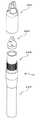
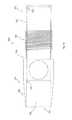
- FIG. 1illustrates an elevational view of an optical obturator system, in accordance with a first embodiment of the present invention
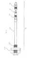
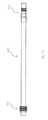
- FIG. 2illustrates a side view of an optical obturator system, in accordance with a second embodiment of the present invention
- FIG. 3illustrates an exploded view of an optical obturator system, in accordance with a third embodiment of the present invention
- FIG. 4illustrates a partial exploded view of a distal portion of an optical obturator system, in accordance with a fourth embodiment of the present invention
- FIG. 5illustrates an elevational view of a tip member of an optical obturator system, in accordance with a fifth embodiment of the present invention
- FIG. 6illustrates a side elevational view of a tip member of an optical obturator system, in accordance with a sixth embodiment of the present invention
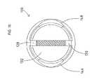
- FIG. 7illustrates a bottom plan view of a tip member of an optical obturator system, in accordance with a seventh embodiment of the present invention
- FIG. 8illustrates a sectional view of the tip member depicted in FIG. 5 , in accordance with an eighth embodiment of the present invention.
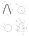
- FIG. 9illustrates a sectional view of the tip member depicted in FIG. 6 , in accordance with a ninth embodiment of the present invention.
- FIG. 10illustrates a partial sectional view of the tip member depicted in FIG. 7 , in accordance with a tenth embodiment of the present invention
- FIG. 11illustrates an elevational view of a transparent window member of an optical obturator system, in accordance with an eleventh embodiment of the present invention
- FIG. 12illustrates a sectional view of a transparent window member of an optical obturator system, in accordance with a twelfth embodiment of the present invention
- FIG. 13illustrates a top plan view of a transparent window member of an optical obturator system, in accordance with a thirteenth embodiment of the present invention
- FIG. 14illustrates a bottom plan view of a transparent window member of an optical obturator system, in accordance with a fourteenth embodiment of the present invention
- FIG. 15illustrates an elevational view of a retainer member of an optical obturator system, in accordance with a fifteenth embodiment of the present invention
- FIG. 16illustrates a top plan view of a retainer member of an optical obturator system, in accordance with a sixteenth embodiment of the present invention
- FIG. 17illustrates a sectional view of the retainer member depicted in FIG. 15 , in accordance with a seventeenth embodiment of the present invention
- FIG. 18illustrates a torn away view of a tip member/retainer member assembly, in accordance with an eighteenth embodiment of the present invention
- FIG. 19illustrates an elevational view of a shaft member of an optical obturator system, in accordance with a nineteenth embodiment of the present invention.
- FIG. 20illustrates a sectional view taken along line I-I of FIG. 19 , in accordance with a twentieth embodiment of the present invention
- FIG. 21illustrates an elevational view of a connector member of an optical obturator system, in accordance with a twenty-first embodiment of the present invention
- FIG. 22illustrates a top plan view of a connector member of an optical obturator system, in accordance with a twenty-second embodiment of the present invention
- FIG. 23illustrates an elevational view of a connector member/shaft member/retainer member assembly of an optical obturator system, in accordance with a twenty-third embodiment of the present invention
- FIG. 24illustrates an elevational view of a handle member of an optical obturator system, in accordance with a twenty-fourth embodiment of the present invention
- FIG. 25illustrates a top plan view of a handle member of an optical obturator system, in accordance with a twenty-fifth embodiment of the present invention
- FIG. 26illustrates a bottom plan view of a handle member of an optical obturator system, in accordance with a twenty-sixth embodiment of the present invention
- FIG. 27illustrates a sectional view taken along line II-II of FIG. 26 , in accordance with a twenty-seventh embodiment of the present invention
- FIG. 28illustrates an elevational view of an optical obturator/cannula assembly, in accordance with a twenty-eighth embodiment of the present invention
- FIG. 29illustrates a sectional view of an optical obturator/cannula assembly, in accordance with a twenty-ninth embodiment of the present invention.
- FIG. 30illustrates an elevational view of an optical obturator/cannula/imaging system assembly, in accordance with a thirtieth embodiment of the present invention.
- FIG. 31illustrates a perspective view of an optical obturator/cannula/imaging system assembly, in accordance with a thirty-first embodiment of the present invention.
- the optical obturator system 10primarily includes a tip member 100 , a transparent window member 200 , a retainer member 300 , a shaft member 400 , a connector member 500 , and a handle member 600 . It should be appreciated that the optical obturator system 10 of the present invention may be operable to interoperate with a cannula or similar device during a surgical procedure.
- the tip member 100may include a proximal portion 110 and a distal portion 112 .
- the proximal portion 110may include a substantially cylindrically shaped body 114 including an open end 116 and an annular wall member 117 defining a bore 118 extending therefrom towards the distal portion 112 .
- a threaded portion 120may be formed on a portion of a wall surface 122 of the bore 118 .
- a portion of the wall surface 122may include an area defining an annular shoulder 124 in proximity to the proximal portion of the threaded portion 120 , and may further define a wall surface 126 of increased diameter as compared to that of the wall surface 122 .
- the distal portion 112may include a pair of tapered arm members 128 , 130 , respectively, that may define a cavity 132 .
- the cavity 132may communicate with the bore 118 such that an object, e.g., the transparent window member 200 , may be introduced into the open end 116 of the bore 118 and be positioned in the cavity 132 .
- the arm member 128 , 130respectively, may be joined or otherwise formed together at a distal portion 134 to provide a substantially conical surface 135 .
- excess materialmay be removed (e.g., by grinding, etching, and/or the like) from the distal portion 112 to form and/or define the cavity 132 and/or the arm members, 128 , 130 , respectively, e.g., to include the desired taper profile.
- a rounded or semi-hemispherical blunt surface 136may be formed on the terminus of the distal portion 134 , e.g., to prevent unintended penetration of the patient's tissues.
- One or more cutting surfaces 138 , 140 , 142 , 144 , respectively,may be formed on the edge surfaces of the arm member 128 , 130 , respectively.
- one or more areas defining a curved, arcuate or scallop-shaped aperture 146 , 148 , respectively,may be formed in the body 150 of the distal portion 112 to permit enhanced viewing capability, e.g., at 90 degrees perpendicular to the respective cutting surfaces.
- the cutting surfacesmay be selectively operable to cut through various bodily tissues so as to penetrate a patient's bodily cavities. That is, the cutting surfaces may be formed with areas of sufficient sharpness so as to penetrate and cut through tissue without undue effort by the surgeon.
- the distal portion 112may also include a wall surface 152 having a decreased diameter as compared to that of either the wall surface 122 or wall surface 126 . In this manner, a shoulder 154 may be defined between wall surface 152 and wall surface 122 .
- the tip member 100may be comprised of a biocompatible material, such as but not limited to stainless steel.
- the chosen materialis preferably suitable to be sterilized by conventional methods numerous times without any appreciable degradation or loss of function.
- the transparent window member 200may include a proximal portion 210 and a distal portion 212 .
- the proximal portion 210may include a circular annular surface 214 .
- the distal portion 212may include a conical portion 216 , wherein the surfaces thereof may taper towards a rounded or blunt terminus 218 .
- An area defining a hollow core or cavity 219may be formed in the proximal portion 210 and may extend into the conical portion 216 , e.g., near or proximate to the terminus 218 .
- the cavity 219may reduce material requirements and/or to permit access of a camera system and/or illumination system closer to the distal portion 212 (e.g., the conical portion 216 ).
- the transparent window member 200may be configured to eliminate any angled surfaces (e.g., 90 degree angles) that might potentially interfere with the ability of the surgeon to clearly view the surgical environment (e.g., the patient's tissues).
- the transparent window member 200may be sized and configured so as to be operable to be at least partially, and more preferably, fully received within the cavity 132 of the tip member 100 and held in place by the arm members, 128 , 130 , respectively.
- the diameter of the proximal portion 210may be sized so as to allow the transparent window member 200 to pass relatively freely through bore 118 and past wall surfaces 122 , 126 , and/or 152 , respectively.
- the transparent window member 200may be comprised of a biocompatible material, such as but not limited to polycarbonate and/or other suitable plastic materials.
- the chosen materialis preferably suitable to be sterilized by conventional methods numerous times without any appreciable degradation or loss of function. It should be appreciated that although the transparent window member 200 may be reused several times, it may also be suitable for use as a single use component.
- an imaging systemsuch as but not limited to a camera system, illumination system, and/or display system, may be introduced through bore 118 and then into or proximate to the cavity 219 of the transparent window member 200 .
- the imaging systemmay then be used by the surgeon, or other healthcare personnel, to view the tissue of the patient that is being engaged and/or cut by the optical obturator system 10 .
- the surgeoncan more easily see the surgical environment (e.g., the patient's tissues) that the optical obturator system 10 is proximate to, and therefore, can ensure that only those tissues that are intended to be engaged are actually engaged.
- the arm members, 128 , 130may be sized so as to avoid any diminishment in visibility through the transparent window member 200 .
- the arm members, 128 , 130may be configured as a single piece core with a 0.030 inches wide cutting/dilating surface.
- the arm members, 128 , 130will not be visible through the transparent window member 200 , e.g., when the surgeon is viewing the same.
- the intended purpose of the retainer member 300is to secure the transparent window member 200 in the tip member 100 , specifically the cavity 132 , to prevent any unintended relative movement.
- the retainer member 300may include a proximal portion 310 and a distal portion 312 .
- the proximal portion 310may include an open end 314 and a tapered annular wall surface 316 defining a bore 318 that extends completely through to the distal portion 312 so as to allow instrumentation to pass there through.
- the annular wall surface 316may include an area defining an internal annular shoulder surface 319 .
- At an opposed end of the annular wall surface 316there may be an area defining an external annular shoulder surface 320 .
- the distal portion 312may include a body member 322 with a threaded surface 324 formed on a portion thereof. At the end of the body member 322 , there may be formed an annular shoulder surface 326 formed on an internal surface of the bore 318 .
- the retainer member 300may be comprised of a biocompatible material, such as but not limited to stainless steel.
- the chosen materialis preferably suitable to be sterilized by conventional methods numerous times without any appreciable degradation or loss of function.
- the retainer member 300is intended to engage the tip member 100 so as to retain the transparent window member 200 therein.
- the retainer member 300 and the tip member 100may be brought into engagement such that the distal portion 314 of the retainer member 300 may be received in the bore 118 of the tip member 100 .
- the threaded surface 120 of the tip member 100 and the threaded surface 324 of the retainer member 300may be brought into threaded engagement with one another.
- relative movement of the tip member 100 and the retainer member 300may cease when the shoulder surface 326 engages the shoulder 154 and/or the wall member 117 engages the shoulder surface 320 .
- the tip member 100 and/or transparent window member 200may be removed from the retainer member 300 (e.g., via the threaded surface 324 of the retainer member 300 ) and either sterilized for additional uses and/or replaced by another sterile tip member 100 and/or transparent window member 200 , without having to dispose of the other major components of the optical obturator system 10 .
- An adhesivee.g., temporary and/or permanent
- suitable materialmay be used to secure the attachment of the tip member 100 and the retainer member 300 . It should be appreciated that the tip member 100 may be removed from the retainer member 300 at a subsequent later time, e.g., for sterilization purposes.
- the shaft member 400is shown as being substantially cylindrical with an area defining a bore 402 extending completely there through so as to allow instrumentation to pass there through.
- the shaft member 400may be comprised of a biocompatible material, such as but not limited to stainless steel.
- the chosen materialis preferably suitable to be sterilized by conventional methods numerous times without any appreciable degradation or loss of function.
- the proximal portion 310 of the retainer member 300is intended to be joined to a distal end 404 of the shaft member 400 by any number of methods including, but not limited to brazing and/or the like. It should be appreciated that the retainer member 300 may be removed from the shaft member 400 at a subsequent later time, e.g., for sterilization purposes. Alternatively, the retainer member 300 and the shaft member 400 may be formed integrally together from a single piece of material.
- the connector member 500may include a body portion 502 having a threaded surface 504 formed on an external surface thereof. An area defining a bore 506 may be formed through the body portion 502 so as to allow instrumentation to pass there through.
- a proximal portion 406 of the shaft member 400is intended to be joined to the connector member 500 by placing the distal portion 406 through the bore 506 and securing thereto by any number of methods including, but not limited to brazing and/or the like.
- the shaft member 400may be removed from the connector member 500 at a subsequent later time, e.g., for sterilization purposes.
- the connector member 500 and the shaft member 400may be formed integrally together from a single piece of material.
- the connector member 500may be comprised of a biocompatible material, such as but not limited to stainless steel.
- the chosen materialis preferably suitable to be sterilized by conventional methods numerous times without any appreciable degradation or loss of function.
- the handle member 600may be comprised of a biocompatible material, such as but not limited to thermoplastics, such as but not limited to polyphenylsulfone, such as but not limited to RADEL® R-5500 (Solvay Advanced Polymers L.L.C., Alpharetta Ga.).
- the chosen materialis preferably suitable to be sterilized by conventional methods numerous times without any appreciable degradation or loss of function.
- the handle member 600may include a body portion 602 having a threaded surface 604 formed on an internal surface thereof. An area defining a bore 606 may be formed through the body portion 602 so as to allow instrumentation to pass there through.
- One or more seal memberse.g., comprised of silicone
- the connector member 500may be joined to the handle member 600 by threadingly engaging the threaded surface 604 of the handle member 600 to the threaded surface 504 of the connector member 500 . It should be appreciated that the connector member 500 may be removed from the handle member 600 at a subsequent later time, e.g., for sterilization purposes. Alternatively, the handle member 600 and the connector member 500 may be formed integrally together from a single piece of material.
- the optical obturator system 10 of the present inventionmay be comprised of materials that can be sterilized many times without any degradation of the materials, the optical obturator system 10 , including the major component parts thereof, may be reusable and can thus may be used for a relatively large number of surgical procedures, assuming conventional sterilization techniques are employed after each surgical procedure.
- FIGS. 28-31there is shown several views of the optical obturator system 10 operably associated with a cannula system 700 , including a cannula member 710 .
- An optional port system 800is shown providing an access system 900 for introducing instrumentation, such as an imaging system, there through so as to be positioned proximate to the transparent window member 200 .
Landscapes
- Health & Medical Sciences (AREA)
- Surgery (AREA)
- Life Sciences & Earth Sciences (AREA)
- Biomedical Technology (AREA)
- Nuclear Medicine, Radiotherapy & Molecular Imaging (AREA)
- Engineering & Computer Science (AREA)
- Pathology (AREA)
- Heart & Thoracic Surgery (AREA)
- Medical Informatics (AREA)
- Molecular Biology (AREA)
- Animal Behavior & Ethology (AREA)
- General Health & Medical Sciences (AREA)
- Public Health (AREA)
- Veterinary Medicine (AREA)
- Endoscopes (AREA)
Abstract
Description
Claims (14)
Priority Applications (1)
| Application Number | Priority Date | Filing Date | Title |
|---|---|---|---|
| US13/872,856US9186173B2 (en) | 2012-04-27 | 2013-04-29 | Optical obturator system |
Applications Claiming Priority (2)
| Application Number | Priority Date | Filing Date | Title |
|---|---|---|---|
| US201261639225P | 2012-04-27 | 2012-04-27 | |
| US13/872,856US9186173B2 (en) | 2012-04-27 | 2013-04-29 | Optical obturator system |
Publications (2)
| Publication Number | Publication Date |
|---|---|
| US20130289600A1 US20130289600A1 (en) | 2013-10-31 |
| US9186173B2true US9186173B2 (en) | 2015-11-17 |
Family
ID=49477940
Family Applications (1)
| Application Number | Title | Priority Date | Filing Date |
|---|---|---|---|
| US13/872,856Active2034-08-02US9186173B2 (en) | 2012-04-27 | 2013-04-29 | Optical obturator system |
Country Status (1)
| Country | Link |
|---|---|
| US (1) | US9186173B2 (en) |
Cited By (1)
| Publication number | Priority date | Publication date | Assignee | Title |
|---|---|---|---|---|
| US10543018B2 (en) | 2015-05-15 | 2020-01-28 | Covidien Lp | Surgical access device |
Families Citing this family (1)
| Publication number | Priority date | Publication date | Assignee | Title |
|---|---|---|---|---|
| BR112015022987A2 (en)* | 2013-03-15 | 2017-07-18 | Olive Medical Corp | integrated prism trocar visualization for use with angled endoscope |
Citations (92)
| Publication number | Priority date | Publication date | Assignee | Title |
|---|---|---|---|---|
| US5242412A (en) | 1992-01-21 | 1993-09-07 | Blake Joseph W Iii | Trocar tube subassembly having sealing ring and duckbill sealing tube having planar, truncate, diverging sealing bills |
| US5246425A (en)* | 1992-09-21 | 1993-09-21 | Daniel Hunsberger | Trocar and cannula assembly |
| US5256149A (en) | 1992-02-14 | 1993-10-26 | Ethicon, Inc. | Trocar having transparent cannula and method of using |
| US5271380A (en)* | 1990-11-06 | 1993-12-21 | Siegfried Riek | Penetration instrument |
| US5330501A (en)* | 1991-05-30 | 1994-07-19 | United States Surgical Corporation | Tissue gripping device for use with a cannula and a cannula incorporating the device |
| US5334150A (en) | 1992-11-17 | 1994-08-02 | Kaali Steven G | Visually directed trocar for laparoscopic surgical procedures and method of using same |
| US5364372A (en) | 1993-03-29 | 1994-11-15 | Endoscopic Concepts, Inc. | Trocar and cannula |
| US5366445A (en) | 1993-03-30 | 1994-11-22 | Habley Medical Technology Corp. | Trocar with rotating safety shield |
| US5385572A (en) | 1992-11-12 | 1995-01-31 | Beowulf Holdings | Trocar for endoscopic surgery |
| US5387197A (en) | 1993-02-25 | 1995-02-07 | Ethicon, Inc. | Trocar safety shield locking mechanism |
| US5387196A (en) | 1992-05-19 | 1995-02-07 | United States Surgical Corporation | Cannula assembly having conductive cannula |
| EP0665029A2 (en) | 1994-01-27 | 1995-08-02 | Sheridan Catheter Corp. | Esophageal-tracheal double lumen airway |
| US5441041A (en) | 1993-09-13 | 1995-08-15 | United States Surgical Corporation | Optical trocar |
| US5449370A (en) | 1993-05-12 | 1995-09-12 | Ethicon, Inc. | Blunt tipped ultrasonic trocar |
| US5467762A (en)* | 1993-09-13 | 1995-11-21 | United States Surgical Corporation | Optical trocar |
| US5545150A (en) | 1994-05-06 | 1996-08-13 | Endoscopic Concepts, Inc. | Trocar |
| US5569292A (en) | 1995-02-01 | 1996-10-29 | Ethicon Endo-Surgery, Inc. | Surgical penetration instrument with transparent blades and tip cover |
| US5569291A (en) | 1995-02-01 | 1996-10-29 | Ethicon Endo-Surgery, Inc. | Surgical penetration and dissection instrument |
| US5591192A (en) | 1995-02-01 | 1997-01-07 | Ethicon Endo-Surgery, Inc. | Surgical penetration instrument including an imaging element |
| US5603702A (en) | 1994-08-08 | 1997-02-18 | United States Surgical Corporation | Valve system for cannula assembly |
| US5620456A (en) | 1995-10-20 | 1997-04-15 | Lasersurge, Inc. | Trocar assembly |
| US5685820A (en)* | 1990-11-06 | 1997-11-11 | Partomed Medizintechnik Gmbh | Instrument for the penetration of body tissue |
| US5697913A (en) | 1996-08-09 | 1997-12-16 | Ethicon Endo-Surgery, Inc. | Trocar including cannula with stepped region |
| US5709671A (en) | 1995-10-16 | 1998-01-20 | Ethicon Endo-Surgery, Inc. | Trocar having an improved tip configuration |
| US5738628A (en)* | 1995-03-24 | 1998-04-14 | Ethicon Endo-Surgery, Inc. | Surgical dissector and method for its use |
| US5817061A (en)* | 1997-05-16 | 1998-10-06 | Ethicon Endo-Surgery, Inc. | Trocar assembly |
| US5860996A (en) | 1994-05-26 | 1999-01-19 | United States Surgical Corporation | Optical trocar |
| US5868714A (en) | 1996-09-16 | 1999-02-09 | Endoscopic Concepts, Inc. | Trocar reducer system |
| US5904699A (en) | 1997-09-19 | 1999-05-18 | Ethicon Endo-Surgery, Inc. | Trocar for penetration and skin incision |
| US5916232A (en) | 1997-10-10 | 1999-06-29 | Applied Medical Resources Corporation | Asymmetrical obturator |
| US5957947A (en) | 1997-07-18 | 1999-09-28 | Wattiez; Arnaud | Single use trocar assembly |
| US5957888A (en) | 1995-10-10 | 1999-09-28 | United States Surgical Corporation | Surgical cannula having a variable length |
| US5980493A (en) | 1995-10-20 | 1999-11-09 | United States Surgical Corporation | Modular trocar system and methods and assembly |
| US5984908A (en) | 1997-04-10 | 1999-11-16 | Chase Medical Inc | Venous return catheter having integral support member |
| US6017356A (en) | 1997-09-19 | 2000-01-25 | Ethicon Endo-Surgery Inc. | Method for using a trocar for penetration and skin incision |
| US6228061B1 (en) | 1998-02-03 | 2001-05-08 | Imagyn Medical Technologies California, Inc. | Trocar seal system having dual seals |
| US6319266B1 (en) | 2000-03-16 | 2001-11-20 | United States Surgical Corporation | Trocar system and method of use |
| US6371967B1 (en) | 1997-06-30 | 2002-04-16 | Ethicon Endo-Surgery, Inc. | Inductively coupled electrosurgical instrument |
| US20020072713A1 (en) | 2000-05-24 | 2002-06-13 | Surgical Innovations Ltd. | Surgical seal |
| US6471638B1 (en)* | 2000-04-28 | 2002-10-29 | Origin Medsystems, Inc. | Surgical apparatus |
| US20020183775A1 (en)* | 2001-06-01 | 2002-12-05 | Mark Tsonton | Trocar with reinforced obturator shaft |
| US6630947B1 (en)* | 1996-04-10 | 2003-10-07 | The United States Of America As Represented By The Secretary Of The Navy | Method for examining subsurface environments |
| US6666846B1 (en) | 1999-11-12 | 2003-12-23 | Edwards Lifesciences Corporation | Medical device introducer and obturator and methods of use |
| US6702787B2 (en) | 1997-05-02 | 2004-03-09 | Tyco Healthcare Group Lp | Trocar seal system |
| DE10333956A1 (en) | 2003-07-25 | 2005-02-17 | Richard Wolf Gmbh | Viewing obturator, comprising removable inner shaft with transparent penetration tip |
| US20050070947A1 (en) | 2003-09-30 | 2005-03-31 | Franer Paul T. | Rotational latching system for a trocar |
| US20050070850A1 (en) | 2003-09-30 | 2005-03-31 | Albrecht Thomas E. | Low-profile, recessed stop-cock valve for trocar assembly |
| US20050149096A1 (en) | 2003-12-23 | 2005-07-07 | Hilal Said S. | Catheter with conduit traversing tip |
| US6923783B2 (en) | 2000-02-25 | 2005-08-02 | United States Surgical Corporation | Valve assembly |
| US20050203559A1 (en) | 2004-03-11 | 2005-09-15 | O'heeron Peter T. | Obturator tip |
| US7025747B2 (en) | 2000-10-13 | 2006-04-11 | Tyco Healthcare Group Lp | Valve assembly including diameter reduction structure for trocar |
| US20060173479A1 (en)* | 2005-01-28 | 2006-08-03 | Smith Robert C | Optical penetrating adapter for surgical portal |
| EP1707132A2 (en) | 2005-03-31 | 2006-10-04 | Tyco Healthcare Group Lp | Optical obturator |
| US20060264992A1 (en) | 2003-09-30 | 2006-11-23 | Ethicon Endo-Surgery, Inc. | Button latching system for a trocar |
| US20070010842A1 (en) | 2003-06-22 | 2007-01-11 | Sergey Popov | Safety trocar obturator |
| US20070088277A1 (en) | 2005-10-14 | 2007-04-19 | Applied Medical Resources Corporation | Surgical access port |
| US20070093851A1 (en) | 2003-06-13 | 2007-04-26 | Koninklijke Philips Electronics N.V. | Surgical seal |
| USD542918S1 (en) | 2005-02-08 | 2007-05-15 | Ethicon Endo-Surgery, Inc. | Trocar |
| US20070129719A1 (en)* | 2005-05-26 | 2007-06-07 | Amar Kendale | Apparatus and methods for performing minimally-invasive surgical procedures |
| US20070185453A1 (en) | 2003-03-21 | 2007-08-09 | Michael Cropper S | Conical trocar seal |
| US20070260273A1 (en)* | 2006-05-08 | 2007-11-08 | Ethicon Endo-Surgery, Inc. | Endoscopic Translumenal Surgical Systems |
| US20070260275A1 (en) | 2006-05-03 | 2007-11-08 | Applied Medical Resources Corporation | Flat blade shielded obturator |
| US20080086074A1 (en) | 2006-10-06 | 2008-04-10 | Applied Medical Presources Corporation | Visual insufflation port |
| US20080103439A1 (en)* | 2006-10-04 | 2008-05-01 | Pathway Medical Technologies, Inc. | Interventional catheters incorporating an active aspiration system |
| US7384423B1 (en)* | 1995-07-13 | 2008-06-10 | Origin Medsystems, Inc. | Tissue dissection method |
| US20080215033A1 (en)* | 2004-04-16 | 2008-09-04 | Kyphon, Inc. | Spinal diagnostic methods and apparatus |
| US20080294184A1 (en)* | 2007-05-22 | 2008-11-27 | Tyco Healthcare Group Lp | Access sheath with blade |
| US20090069806A1 (en)* | 2005-05-11 | 2009-03-12 | Mayo Foundation For Medical And Research | Apparatus and methods for internal surgical procedures |
| US20090093833A1 (en) | 2007-10-05 | 2009-04-09 | Tyco Healthcare Group Lp | Bladeless obturator for use in a surgical trocar assembly |
| US20090177030A1 (en)* | 2007-11-28 | 2009-07-09 | Hiroaki Goto | Endoscopic incision system |
| US7585288B2 (en) | 2004-01-23 | 2009-09-08 | Genico, Inc. | Trocar and cannula assembly having conical valve and related methods |
| US7597701B2 (en) | 2003-09-30 | 2009-10-06 | Ethican Endo-Surgery, Inc. | Instrument lock assembly for trocar |
| US20090270817A1 (en) | 2008-04-28 | 2009-10-29 | Ethicon Endo-Surgery, Inc. | Fluid removal in a surgical access device |
| US20090281386A1 (en) | 2006-04-19 | 2009-11-12 | Acosta Pablo G | Devices, system and methods for minimally invasive abdominal surgical procedures |
| US20090281498A1 (en) | 2006-04-19 | 2009-11-12 | Acosta Pablo G | Devices, system and methods for minimally invasive abdominal surgical procedures |
| US20090281500A1 (en) | 2006-04-19 | 2009-11-12 | Acosta Pablo G | Devices, system and methods for minimally invasive abdominal surgical procedures |
| US20090281376A1 (en) | 2006-04-19 | 2009-11-12 | Acosta Pablo G | Devices, system and methods for minimally invasive abdominal surgical procedures |
| US20090306698A1 (en)* | 2006-12-14 | 2009-12-10 | Aesculap Ag | Surgical obturator |
| US7637896B2 (en) | 2005-03-30 | 2009-12-29 | Ethicon Endo-Surgery, Inc. | Obturator tip assembly for a trocar |
| US20100016664A1 (en) | 2006-12-20 | 2010-01-21 | Tyco Healthcare Group Lp | Surgical visual obturator |
| US20100022959A1 (en) | 2006-08-25 | 2010-01-28 | Stuart Moran | Cannula sealing apparatus |
| US20100053312A1 (en)* | 2006-11-28 | 2010-03-04 | Olympus Corporation | Endoscope apparatus |
| US7686823B2 (en) | 2001-09-24 | 2010-03-30 | Applied Medical Resources, Corporation | Bladeless obturator |
| US20100081988A1 (en)* | 2008-09-29 | 2010-04-01 | Applies Medical Resources Corporation | First-entry trocar system |
| US20100137895A1 (en) | 2007-04-17 | 2010-06-03 | Smith Robert C | Visual obturator with handle |
| US7758603B2 (en) | 2002-05-16 | 2010-07-20 | Applied Medical Resources Corporation | Blunt tip obturator |
| US7794644B2 (en) | 2005-10-05 | 2010-09-14 | Applied Medical Resources Corporation | Thin-walled optical obturator |
| US7824327B2 (en) | 2005-04-12 | 2010-11-02 | Tyco Healthcare Group Llp | Optical trocar with scope holding assembly |
| US7918826B2 (en) | 2007-09-14 | 2011-04-05 | Ethicon Endo-Surgery, Inc. | Trocar assembly |
| US7947058B2 (en) | 2001-09-24 | 2011-05-24 | Applied Medical Resources Corporation | Bladeless optical obturator |
| US7967791B2 (en) | 2007-07-23 | 2011-06-28 | Ethicon Endo-Surgery, Inc. | Surgical access device |
| US20110257646A1 (en)* | 1999-07-14 | 2011-10-20 | Mederi Therapeutics Inc. | Method for treating fecal incontinence |
- 2013
- 2013-04-29USUS13/872,856patent/US9186173B2/enactiveActive
Patent Citations (113)
| Publication number | Priority date | Publication date | Assignee | Title |
|---|---|---|---|---|
| US5271380A (en)* | 1990-11-06 | 1993-12-21 | Siegfried Riek | Penetration instrument |
| US5685820A (en)* | 1990-11-06 | 1997-11-11 | Partomed Medizintechnik Gmbh | Instrument for the penetration of body tissue |
| US5330501A (en)* | 1991-05-30 | 1994-07-19 | United States Surgical Corporation | Tissue gripping device for use with a cannula and a cannula incorporating the device |
| US5242412A (en) | 1992-01-21 | 1993-09-07 | Blake Joseph W Iii | Trocar tube subassembly having sealing ring and duckbill sealing tube having planar, truncate, diverging sealing bills |
| JPH07250810A (en) | 1992-02-14 | 1995-10-03 | Ethicon Inc | Trocar with transparent cannula and how to use |
| US5256149A (en) | 1992-02-14 | 1993-10-26 | Ethicon, Inc. | Trocar having transparent cannula and method of using |
| US5387196A (en) | 1992-05-19 | 1995-02-07 | United States Surgical Corporation | Cannula assembly having conductive cannula |
| US5246425A (en)* | 1992-09-21 | 1993-09-21 | Daniel Hunsberger | Trocar and cannula assembly |
| US5385572A (en) | 1992-11-12 | 1995-01-31 | Beowulf Holdings | Trocar for endoscopic surgery |
| US5376076A (en) | 1992-11-17 | 1994-12-27 | Kaali; Steven G. | Visually directed trocar for laparoscopic surgical procedures and method of using same |
| US5380291A (en) | 1992-11-17 | 1995-01-10 | Kaali; Steven G. | Visually directed trocar for laparoscopic surgical procedures and method of using same |
| US5334150A (en) | 1992-11-17 | 1994-08-02 | Kaali Steven G | Visually directed trocar for laparoscopic surgical procedures and method of using same |
| US5387197A (en) | 1993-02-25 | 1995-02-07 | Ethicon, Inc. | Trocar safety shield locking mechanism |
| US5364372A (en) | 1993-03-29 | 1994-11-15 | Endoscopic Concepts, Inc. | Trocar and cannula |
| US5366445A (en) | 1993-03-30 | 1994-11-22 | Habley Medical Technology Corp. | Trocar with rotating safety shield |
| US5449370A (en) | 1993-05-12 | 1995-09-12 | Ethicon, Inc. | Blunt tipped ultrasonic trocar |
| US5441041A (en) | 1993-09-13 | 1995-08-15 | United States Surgical Corporation | Optical trocar |
| US5658236A (en) | 1993-09-13 | 1997-08-19 | United States Surgical Corporation | Optical trocar |
| US7322933B2 (en) | 1993-09-13 | 2008-01-29 | United States Surgical Corporation | Optical trocar |
| US6685630B2 (en) | 1993-09-13 | 2004-02-03 | United States Surgical Corporation | Optical trocar |
| US5569160A (en) | 1993-09-13 | 1996-10-29 | United States Surgical Corporation | Optical trocar |
| US5467762A (en)* | 1993-09-13 | 1995-11-21 | United States Surgical Corporation | Optical trocar |
| US5499625A (en) | 1994-01-27 | 1996-03-19 | The Kendall Company | Esophageal-tracheal double lumen airway |
| EP0665029A2 (en) | 1994-01-27 | 1995-08-02 | Sheridan Catheter Corp. | Esophageal-tracheal double lumen airway |
| US5797943A (en) | 1994-05-06 | 1998-08-25 | Endoscopic Concepts, Inc. | Shielded trocar and trocar shield |
| US5607440A (en) | 1994-05-06 | 1997-03-04 | Endoscopic Concepts, Inc. | Trocar with lockable shield |
| US6063099A (en) | 1994-05-06 | 2000-05-16 | Endoscopic Concepts, Inc. | Dilating trocar shield with blade tip |
| US5545150A (en) | 1994-05-06 | 1996-08-13 | Endoscopic Concepts, Inc. | Trocar |
| US5860996A (en) | 1994-05-26 | 1999-01-19 | United States Surgical Corporation | Optical trocar |
| US5895377A (en) | 1994-08-08 | 1999-04-20 | United States Surgical Corporation | Valve system for cannula assembly |
| US5603702A (en) | 1994-08-08 | 1997-02-18 | United States Surgical Corporation | Valve system for cannula assembly |
| US5569292A (en) | 1995-02-01 | 1996-10-29 | Ethicon Endo-Surgery, Inc. | Surgical penetration instrument with transparent blades and tip cover |
| US5591192A (en) | 1995-02-01 | 1997-01-07 | Ethicon Endo-Surgery, Inc. | Surgical penetration instrument including an imaging element |
| US5569291A (en) | 1995-02-01 | 1996-10-29 | Ethicon Endo-Surgery, Inc. | Surgical penetration and dissection instrument |
| US5738628A (en)* | 1995-03-24 | 1998-04-14 | Ethicon Endo-Surgery, Inc. | Surgical dissector and method for its use |
| US7384423B1 (en)* | 1995-07-13 | 2008-06-10 | Origin Medsystems, Inc. | Tissue dissection method |
| US5957888A (en) | 1995-10-10 | 1999-09-28 | United States Surgical Corporation | Surgical cannula having a variable length |
| US5709671A (en) | 1995-10-16 | 1998-01-20 | Ethicon Endo-Surgery, Inc. | Trocar having an improved tip configuration |
| US5620456A (en) | 1995-10-20 | 1997-04-15 | Lasersurge, Inc. | Trocar assembly |
| US5980493A (en) | 1995-10-20 | 1999-11-09 | United States Surgical Corporation | Modular trocar system and methods and assembly |
| US6630947B1 (en)* | 1996-04-10 | 2003-10-07 | The United States Of America As Represented By The Secretary Of The Navy | Method for examining subsurface environments |
| US5697913A (en) | 1996-08-09 | 1997-12-16 | Ethicon Endo-Surgery, Inc. | Trocar including cannula with stepped region |
| US5868714A (en) | 1996-09-16 | 1999-02-09 | Endoscopic Concepts, Inc. | Trocar reducer system |
| US5984908A (en) | 1997-04-10 | 1999-11-16 | Chase Medical Inc | Venous return catheter having integral support member |
| US6702787B2 (en) | 1997-05-02 | 2004-03-09 | Tyco Healthcare Group Lp | Trocar seal system |
| US5817061A (en)* | 1997-05-16 | 1998-10-06 | Ethicon Endo-Surgery, Inc. | Trocar assembly |
| US6371967B1 (en) | 1997-06-30 | 2002-04-16 | Ethicon Endo-Surgery, Inc. | Inductively coupled electrosurgical instrument |
| US5957947A (en) | 1997-07-18 | 1999-09-28 | Wattiez; Arnaud | Single use trocar assembly |
| US6017356A (en) | 1997-09-19 | 2000-01-25 | Ethicon Endo-Surgery Inc. | Method for using a trocar for penetration and skin incision |
| US5904699A (en) | 1997-09-19 | 1999-05-18 | Ethicon Endo-Surgery, Inc. | Trocar for penetration and skin incision |
| US5916232A (en) | 1997-10-10 | 1999-06-29 | Applied Medical Resources Corporation | Asymmetrical obturator |
| US6228061B1 (en) | 1998-02-03 | 2001-05-08 | Imagyn Medical Technologies California, Inc. | Trocar seal system having dual seals |
| US20110257646A1 (en)* | 1999-07-14 | 2011-10-20 | Mederi Therapeutics Inc. | Method for treating fecal incontinence |
| US6666846B1 (en) | 1999-11-12 | 2003-12-23 | Edwards Lifesciences Corporation | Medical device introducer and obturator and methods of use |
| US7559918B2 (en) | 2000-02-25 | 2009-07-14 | Joseph Pasqualucci | Valve assembly |
| US6923783B2 (en) | 2000-02-25 | 2005-08-02 | United States Surgical Corporation | Valve assembly |
| US7367960B2 (en) | 2000-03-16 | 2008-05-06 | United States Surgical Corporation | Trocar system and method of use |
| US6319266B1 (en) | 2000-03-16 | 2001-11-20 | United States Surgical Corporation | Trocar system and method of use |
| US6471638B1 (en)* | 2000-04-28 | 2002-10-29 | Origin Medsystems, Inc. | Surgical apparatus |
| US7722570B2 (en) | 2000-05-24 | 2010-05-25 | Applied Medical Resources Corporation | Surgical seal |
| US20020072713A1 (en) | 2000-05-24 | 2002-06-13 | Surgical Innovations Ltd. | Surgical seal |
| US7025747B2 (en) | 2000-10-13 | 2006-04-11 | Tyco Healthcare Group Lp | Valve assembly including diameter reduction structure for trocar |
| US6656198B2 (en) | 2001-06-01 | 2003-12-02 | Ethicon-Endo Surgery, Inc. | Trocar with reinforced obturator shaft |
| US20020183775A1 (en)* | 2001-06-01 | 2002-12-05 | Mark Tsonton | Trocar with reinforced obturator shaft |
| US7947058B2 (en) | 2001-09-24 | 2011-05-24 | Applied Medical Resources Corporation | Bladeless optical obturator |
| US7686823B2 (en) | 2001-09-24 | 2010-03-30 | Applied Medical Resources, Corporation | Bladeless obturator |
| US7758603B2 (en) | 2002-05-16 | 2010-07-20 | Applied Medical Resources Corporation | Blunt tip obturator |
| US20070185453A1 (en) | 2003-03-21 | 2007-08-09 | Michael Cropper S | Conical trocar seal |
| US20070093851A1 (en) | 2003-06-13 | 2007-04-26 | Koninklijke Philips Electronics N.V. | Surgical seal |
| US20070010842A1 (en) | 2003-06-22 | 2007-01-11 | Sergey Popov | Safety trocar obturator |
| DE10333956A1 (en) | 2003-07-25 | 2005-02-17 | Richard Wolf Gmbh | Viewing obturator, comprising removable inner shaft with transparent penetration tip |
| US20060264992A1 (en) | 2003-09-30 | 2006-11-23 | Ethicon Endo-Surgery, Inc. | Button latching system for a trocar |
| US20050070947A1 (en) | 2003-09-30 | 2005-03-31 | Franer Paul T. | Rotational latching system for a trocar |
| US20050070850A1 (en) | 2003-09-30 | 2005-03-31 | Albrecht Thomas E. | Low-profile, recessed stop-cock valve for trocar assembly |
| US7597701B2 (en) | 2003-09-30 | 2009-10-06 | Ethican Endo-Surgery, Inc. | Instrument lock assembly for trocar |
| US20050149096A1 (en) | 2003-12-23 | 2005-07-07 | Hilal Said S. | Catheter with conduit traversing tip |
| US7585288B2 (en) | 2004-01-23 | 2009-09-08 | Genico, Inc. | Trocar and cannula assembly having conical valve and related methods |
| US7320694B2 (en) | 2004-03-11 | 2008-01-22 | Coopersurgical, Inc. | Obturator tip |
| US20050203559A1 (en) | 2004-03-11 | 2005-09-15 | O'heeron Peter T. | Obturator tip |
| US20080215033A1 (en)* | 2004-04-16 | 2008-09-04 | Kyphon, Inc. | Spinal diagnostic methods and apparatus |
| US20060173479A1 (en)* | 2005-01-28 | 2006-08-03 | Smith Robert C | Optical penetrating adapter for surgical portal |
| USD542918S1 (en) | 2005-02-08 | 2007-05-15 | Ethicon Endo-Surgery, Inc. | Trocar |
| US7637896B2 (en) | 2005-03-30 | 2009-12-29 | Ethicon Endo-Surgery, Inc. | Obturator tip assembly for a trocar |
| US20090076323A1 (en) | 2005-03-31 | 2009-03-19 | Tyco Healthcare Group Lp | Optical obturator |
| EP1707132A2 (en) | 2005-03-31 | 2006-10-04 | Tyco Healthcare Group Lp | Optical obturator |
| US7470230B2 (en)* | 2005-03-31 | 2008-12-30 | Tyco Healthcare Group Lp | Optical obturator |
| US7824327B2 (en) | 2005-04-12 | 2010-11-02 | Tyco Healthcare Group Llp | Optical trocar with scope holding assembly |
| US20090069806A1 (en)* | 2005-05-11 | 2009-03-12 | Mayo Foundation For Medical And Research | Apparatus and methods for internal surgical procedures |
| US20070129719A1 (en)* | 2005-05-26 | 2007-06-07 | Amar Kendale | Apparatus and methods for performing minimally-invasive surgical procedures |
| US7794644B2 (en) | 2005-10-05 | 2010-09-14 | Applied Medical Resources Corporation | Thin-walled optical obturator |
| US20070088277A1 (en) | 2005-10-14 | 2007-04-19 | Applied Medical Resources Corporation | Surgical access port |
| US20090281498A1 (en) | 2006-04-19 | 2009-11-12 | Acosta Pablo G | Devices, system and methods for minimally invasive abdominal surgical procedures |
| US20090281386A1 (en) | 2006-04-19 | 2009-11-12 | Acosta Pablo G | Devices, system and methods for minimally invasive abdominal surgical procedures |
| US20090281500A1 (en) | 2006-04-19 | 2009-11-12 | Acosta Pablo G | Devices, system and methods for minimally invasive abdominal surgical procedures |
| US20090281376A1 (en) | 2006-04-19 | 2009-11-12 | Acosta Pablo G | Devices, system and methods for minimally invasive abdominal surgical procedures |
| US20070260275A1 (en) | 2006-05-03 | 2007-11-08 | Applied Medical Resources Corporation | Flat blade shielded obturator |
| US20080051735A1 (en) | 2006-05-08 | 2008-02-28 | Ethicon Endo-Surgery, Inc. | Endoscopic translumenal surgical systems |
| US20070260273A1 (en)* | 2006-05-08 | 2007-11-08 | Ethicon Endo-Surgery, Inc. | Endoscopic Translumenal Surgical Systems |
| US20100022959A1 (en) | 2006-08-25 | 2010-01-28 | Stuart Moran | Cannula sealing apparatus |
| US20080103439A1 (en)* | 2006-10-04 | 2008-05-01 | Pathway Medical Technologies, Inc. | Interventional catheters incorporating an active aspiration system |
| US20080086074A1 (en) | 2006-10-06 | 2008-04-10 | Applied Medical Presources Corporation | Visual insufflation port |
| US20100053312A1 (en)* | 2006-11-28 | 2010-03-04 | Olympus Corporation | Endoscope apparatus |
| US20090306698A1 (en)* | 2006-12-14 | 2009-12-10 | Aesculap Ag | Surgical obturator |
| US20100016664A1 (en) | 2006-12-20 | 2010-01-21 | Tyco Healthcare Group Lp | Surgical visual obturator |
| US20100137895A1 (en) | 2007-04-17 | 2010-06-03 | Smith Robert C | Visual obturator with handle |
| US8202290B2 (en)* | 2007-04-17 | 2012-06-19 | Tyco Healthcare Group Lp | Visual obturator with handle |
| US20080294184A1 (en)* | 2007-05-22 | 2008-11-27 | Tyco Healthcare Group Lp | Access sheath with blade |
| US7967791B2 (en) | 2007-07-23 | 2011-06-28 | Ethicon Endo-Surgery, Inc. | Surgical access device |
| US7918826B2 (en) | 2007-09-14 | 2011-04-05 | Ethicon Endo-Surgery, Inc. | Trocar assembly |
| US20090093833A1 (en) | 2007-10-05 | 2009-04-09 | Tyco Healthcare Group Lp | Bladeless obturator for use in a surgical trocar assembly |
| US20090177030A1 (en)* | 2007-11-28 | 2009-07-09 | Hiroaki Goto | Endoscopic incision system |
| US20090270817A1 (en) | 2008-04-28 | 2009-10-29 | Ethicon Endo-Surgery, Inc. | Fluid removal in a surgical access device |
| US20100081988A1 (en)* | 2008-09-29 | 2010-04-01 | Applies Medical Resources Corporation | First-entry trocar system |
Non-Patent Citations (2)
| Title |
|---|
| English Abstract of DE 10333956. |
| English Abstract of JP 7250810. |
Cited By (2)
| Publication number | Priority date | Publication date | Assignee | Title |
|---|---|---|---|---|
| US10543018B2 (en) | 2015-05-15 | 2020-01-28 | Covidien Lp | Surgical access device |
| US11832849B2 (en) | 2015-05-15 | 2023-12-05 | Covidien Lp | Surgical access device |
Also Published As
| Publication number | Publication date |
|---|---|
| US20130289600A1 (en) | 2013-10-31 |
Similar Documents
| Publication | Publication Date | Title |
|---|---|---|
| US8821383B2 (en) | Slotted clear cannula | |
| US10555719B2 (en) | Ultrasound assisted needle puncture mechanism | |
| US10010337B2 (en) | Slotted clear cannula | |
| US8070767B2 (en) | Optical penetrating adapter for surgical portal | |
| JP6400682B2 (en) | Replaceable surgical access port assembly | |
| EP2104461B1 (en) | Access sheath with removable optical penetrating member | |
| EP2228016A1 (en) | Access port including multi-layer seal and suture parks | |
| US20130338694A1 (en) | Optical obturator assembly | |
| US11572906B2 (en) | Trocar packaging clip | |
| AU2009202289B2 (en) | Surgical portal apparatus with waffle seal | |
| US9402536B2 (en) | Obturator features for mating with cannula tube | |
| JP5334130B2 (en) | Obturator assembly | |
| US8821526B2 (en) | Trocar | |
| JP2011125701A (en) | Obturator tip | |
| US9186173B2 (en) | Optical obturator system | |
| EP2213250A1 (en) | Suture management system for surgical portal apparatus including internal tubes | |
| KR102268211B1 (en) | Exchanger surgical access port assembly and methods of use | |
| WO2008095270A1 (en) | Laparoscopic trocar with flexible endoscopic system | |
| EP2368505A1 (en) | Portal apparatus with a tubular seal device |
Legal Events
| Date | Code | Title | Description |
|---|---|---|---|
| AS | Assignment | Owner name:SPECIALTYCARE, INC., TENNESSEE Free format text:ASSIGNMENT OF ASSIGNORS INTEREST;ASSIGNORS:WINFREE, ALAN;ASHBURN, STAN;REEL/FRAME:030335/0811 Effective date:20130501 | |
| AS | Assignment | Owner name:REGIONS BANK, AS AGENT, TENNESSEE Free format text:SECURITY AGREEMENT;ASSIGNOR:SPECIALTYCARE, INC.;REEL/FRAME:031304/0644 Effective date:20130926 | |
| STCF | Information on status: patent grant | Free format text:PATENTED CASE | |
| FEPP | Fee payment procedure | Free format text:PAYOR NUMBER ASSIGNED (ORIGINAL EVENT CODE: ASPN); ENTITY STATUS OF PATENT OWNER: LARGE ENTITY | |
| CC | Certificate of correction | ||
| AS | Assignment | Owner name:ANTARES CAPITAL LP, AS AGENT, ILLINOIS Free format text:TRADEMARK SECURITY AGREEMENT (1L);ASSIGNOR:SPECIALTYCARE, INC.;REEL/FRAME:043747/0351 Effective date:20170901 Owner name:ANTARES CAPITAL LP, AS AGENT, ILLINOIS Free format text:PATENT SECURITY AGREEMENT (2L);ASSIGNOR:SPECIALTYCARE, INC.;REEL/FRAME:043747/0373 Effective date:20170901 | |
| MAFP | Maintenance fee payment | Free format text:PAYMENT OF MAINTENANCE FEE, 4TH YEAR, LARGE ENTITY (ORIGINAL EVENT CODE: M1551); ENTITY STATUS OF PATENT OWNER: LARGE ENTITY Year of fee payment:4 | |
| AS | Assignment | Owner name:ANTARES CAPITAL LP, AS COLLATERAL AGENT, ILLINOIS Free format text:SECURITY INTEREST;ASSIGNOR:SPECIALTYCARE, INC.;REEL/FRAME:056590/0403 Effective date:20210618 Owner name:SPECIALTYCARE, INC., TENNESSEE Free format text:RELEASE OF SECURITY INTEREST IN INTELLECTUAL PROPERTY (1L);ASSIGNOR:ANTARES CAPITAL LP, AS AGENT;REEL/FRAME:056627/0845 Effective date:20210618 | |
| AS | Assignment | Owner name:SPECIALTYCARE, INC., TENNESSEE Free format text:RELEASE OF SECURITY INTEREST IN INTELLECTUAL PROPERTY COLLATERAL (2L);ASSIGNOR:ANTARES CAPITAL LP, AS AGENT;REEL/FRAME:056628/0504 Effective date:20210618 | |
| MAFP | Maintenance fee payment | Free format text:PAYMENT OF MAINTENANCE FEE, 8TH YEAR, LARGE ENTITY (ORIGINAL EVENT CODE: M1552); ENTITY STATUS OF PATENT OWNER: LARGE ENTITY Year of fee payment:8 |