US9186170B2 - Bidirectional expandable head for rotational atherectomy device - Google Patents
Bidirectional expandable head for rotational atherectomy deviceDownload PDFInfo
- Publication number
- US9186170B2 US9186170B2US12/466,130US46613009AUS9186170B2US 9186170 B2US9186170 B2US 9186170B2US 46613009 AUS46613009 AUS 46613009AUS 9186170 B2US9186170 B2US 9186170B2
- Authority
- US
- United States
- Prior art keywords
- drive shaft
- cutting
- arm
- grinding
- rotational
- Prior art date
- Legal status (The legal status is an assumption and is not a legal conclusion. Google has not performed a legal analysis and makes no representation as to the accuracy of the status listed.)
- Expired - Fee Related, expires
Links
- 230000002457bidirectional effectEffects0.000titledescription2
- 239000003082abrasive agentSubstances0.000claimsabstractdescription23
- 230000001154acute effectEffects0.000claimsdescription9
- 239000000463materialSubstances0.000abstractdescription16
- 238000007790scrapingMethods0.000abstractdescription6
- 238000013461designMethods0.000description7
- 210000004351coronary vesselAnatomy0.000description6
- 238000003780insertionMethods0.000description5
- 230000037431insertionEffects0.000description5
- 210000001367arteryAnatomy0.000description4
- 230000000694effectsEffects0.000description4
- 238000012986modificationMethods0.000description4
- 230000004048modificationEffects0.000description4
- 239000002245particleSubstances0.000description4
- 238000001356surgical procedureMethods0.000description4
- 238000000605extractionMethods0.000description3
- 206010008479Chest PainDiseases0.000description2
- 238000002399angioplastyMethods0.000description2
- 239000012530fluidSubstances0.000description2
- 238000009428plumbingMethods0.000description2
- 208000037260Atherosclerotic PlaqueDiseases0.000description1
- FAPWRFPIFSIZLT-UHFFFAOYSA-MSodium chlorideChemical compound[Na+].[Cl-]FAPWRFPIFSIZLT-UHFFFAOYSA-M0.000description1
- 208000007536ThrombosisDiseases0.000description1
- QVGXLLKOCUKJST-UHFFFAOYSA-Natomic oxygenChemical compound[O]QVGXLLKOCUKJST-UHFFFAOYSA-N0.000description1
- 239000008280bloodSubstances0.000description1
- 210000004369bloodAnatomy0.000description1
- 230000036772blood pressureEffects0.000description1
- 210000004204blood vesselAnatomy0.000description1
- 230000000747cardiac effectEffects0.000description1
- 230000006835compressionEffects0.000description1
- 238000007906compressionMethods0.000description1
- 238000001816coolingMethods0.000description1
- 238000011161developmentMethods0.000description1
- 229940079593drugDrugs0.000description1
- 239000003814drugSubstances0.000description1
- 239000000835fiberSubstances0.000description1
- 210000004013groinAnatomy0.000description1
- 230000003902lesionEffects0.000description1
- 230000001050lubricating effectEffects0.000description1
- 238000013160medical therapyMethods0.000description1
- 238000002483medicationMethods0.000description1
- 238000000034methodMethods0.000description1
- 238000012544monitoring processMethods0.000description1
- 208000010125myocardial infarctionDiseases0.000description1
- 229910052760oxygenInorganic materials0.000description1
- 239000001301oxygenSubstances0.000description1
- 238000011160researchMethods0.000description1
- 239000004576sandSubstances0.000description1
- 239000011780sodium chlorideSubstances0.000description1
- 230000002966stenotic effectEffects0.000description1
- 239000000126substanceSubstances0.000description1
- 210000005166vasculatureAnatomy0.000description1
- 210000003462veinAnatomy0.000description1
Images


Classifications
- A—HUMAN NECESSITIES
- A61—MEDICAL OR VETERINARY SCIENCE; HYGIENE
- A61B—DIAGNOSIS; SURGERY; IDENTIFICATION
- A61B17/00—Surgical instruments, devices or methods
- A61B17/32—Surgical cutting instruments
- A61B17/3205—Excision instruments
- A61B17/3207—Atherectomy devices working by cutting or abrading; Similar devices specially adapted for non-vascular obstructions
- A61B17/320725—Atherectomy devices working by cutting or abrading; Similar devices specially adapted for non-vascular obstructions with radially expandable cutting or abrading elements
- A—HUMAN NECESSITIES
- A61—MEDICAL OR VETERINARY SCIENCE; HYGIENE
- A61B—DIAGNOSIS; SURGERY; IDENTIFICATION
- A61B17/00—Surgical instruments, devices or methods
- A61B17/32—Surgical cutting instruments
- A61B17/3205—Excision instruments
- A61B17/3207—Atherectomy devices working by cutting or abrading; Similar devices specially adapted for non-vascular obstructions
- A61B17/320758—Atherectomy devices working by cutting or abrading; Similar devices specially adapted for non-vascular obstructions with a rotating cutting instrument, e.g. motor driven
- A—HUMAN NECESSITIES
- A61—MEDICAL OR VETERINARY SCIENCE; HYGIENE
- A61B—DIAGNOSIS; SURGERY; IDENTIFICATION
- A61B17/00—Surgical instruments, devices or methods
- A61B17/32—Surgical cutting instruments
- A61B2017/320004—Surgical cutting instruments abrasive
Definitions
- the present inventionis directed to expandable abrasive/cutting heads for rotation atherectomy devices.
- Atherectomyis a non-surgical procedure to open blocked coronary arteries or vein grafts by using a device on the end of a catheter to cut or shave away atherosclerotic plaque (a deposit of fat and other substances that accumulate in the lining of the artery wall).
- atherosclerotic plaquea deposit of fat and other substances that accumulate in the lining of the artery wall.
- the term “abrading”is used to describe the grinding and/or scraping action of such an atherectomy head.
- Atherectomyis performed to restore the flow of oxygen-rich blood to the heart, to relieve chest pain, and to prevent heart attacks. It may be done on patients with chest pain who have not responded to other medical therapy and on certain of those who are candidates for balloon angioplasty (a surgical procedure in which a balloon catheter is used to flatten plaque against an artery wall) or coronary artery bypass graft surgery. It is sometimes performed to remove plaque that has built up after a coronary artery bypass graft surgery.
- balloon angioplastya surgical procedure in which a balloon catheter is used to flatten plaque against an artery wall
- coronary artery bypass graft surgeryIt is sometimes performed to remove plaque that has built up after a coronary artery bypass graft surgery.
- Atherectomyuses a rotating shaver or other device placed on the end of a catheter to slice away or destroy plaque.
- medications to control blood pressure, dilate the coronary arteries, and prevent blood clotsare administered.
- the patientis awake but sedated.
- the catheteris inserted into an artery in the groin, leg, or arm, and threaded through the blood vessels into the blocked coronary artery.
- the cutting headis positioned against the plaque and activated, and the plaque is ground up or suctioned out.
- Rotational atherectomyuses a high speed rotating shaver to grind up plaque.
- Directional atherectomywas the first type approved, but is no longer commonly used; it scrapes plaque into an opening in one side of the catheter.
- Transluminal extraction coronary atherectomyuses a device that cuts plaque off vessel walls and vacuums it into a bottle. It is used to clear bypass grafts.
- Atherectomyis also called removal of plaque from the coronary arteries. It can be used instead of, or along with, balloon angioplasty. Atherectomy is successful about 95% of the time. Plaque forms again in 20-30% of patients.
- U.S. Pat. No. 5,360,432issued on Nov. 1, 1994 to Leonid Shturman, and titled “Abrasive drive shaft device for directional rotational atherectomy” discloses an abrasive drive shaft atherectomy device for removing stenotic tissue from an artery, and is incorporated by reference herein in its entirety.
- the deviceincludes a rotational atherectomy apparatus having a flexible, elongated drive shaft having a central lumen and a segment, near its distal end, coated with an abrasive material to define an abrasive segment.
- the abrasive segmentexpands radially, and can sweep out an abrading diameter that is larger than its rest diameter. In this manner, the atherectomy device may remove a blockage that is larger than the catheter itself.
- Use of an expandable headis an improvement over atherectomy devices that use non-expandable heads; such non-expandable devices typically require removal of particular blockages in stages, with each stage using a differently-sized head.
- the abrasive headincludes an abrasive that has a single set of properties.
- an abrasive burrmay include abrasive particles of a particular size or a particular distribution of sizes.
- a particular headmay have a cutting effect on the blockage, rather than a grinding effect.
- a practitionerrequires two different abrading heads for a single blockage.
- a particular blockagemay have hard plaques, which may be effectively removed by sanding or scraping, as well as soft lesions, which may be effectively removed by slicing or cutting.
- the cutting headmay have different properties than the scraping head.
- a practitionerwants to use a first abrasive, then use a second abrasive having different properties than the first abrasive, the practitioner must remove the device with the first abrasive, then insert the device with the second abrasive. This removal of one catheter and insertion of another catheter is time-consuming, inconvenient, expensive, and requires additional parts that must be manufactured, shipped, inventoried, and maintained with the atherectomy device.
- An embodimentis a rotational atherectomy apparatus for abrading tissue, comprising: a flexible, elongated, rotatable drive shaft having a proximal end and a distal end opposite the proximal end, the drive shaft being rotatable in a cutting direction and in a grinding direction opposite the cutting direction; an expandable abrasive element disposed proximate the distal end of the drive shaft, the abrasive element further comprising: a cutting element expandably exposed to tissue when the drive shaft is rotated in the cutting direction at a high rotational speed; a grinding element expandably exposed to tissue when the drive shaft is rotated in the grinding direction at a high rotational speed; and a rotational diameter that is expandably greater than its rest diameter.
- FIG. 1Another embodiment is a rotational atherectomy apparatus, comprising: a flexible, elongated, rotatable drive shaft having a proximal end and a distal end opposite the proximal end, the drive shaft being rotatable in a cutting direction and in a grinding direction opposite the cutting direction; a first arm pivotally attached to the drive shaft at a first drive shaft anchor point near the distal end of the drive shaft, the first arm being pivotable in a first plane tangential to the drive shaft at the first drive shaft anchor point; the first arm having a first arm free end that leads the first drive shaft anchor point when the drive shaft is rotated in the cutting direction and trails the first drive shaft anchor point when the drive shaft is rotated in the grinding direction; the first arm free end having a first cutting feature on a leading edge of the first arm free end as the drive shaft is rotated in the cutting direction; and the first arm free end having a first grinding feature adjacent to the first cutting feature and leading the first cutting feature as the drive shaft is rotated in the grinding direction.
- a rotational atherectomy apparatuscomprising: a flexible, elongated, rotatable drive shaft having a proximal end and a distal end opposite the proximal end, the drive shaft being rotatable in a cutting direction and in a grinding direction opposite the cutting direction; a first arm hingedly attached to the drive shaft at a first drive shaft anchor point near the distal end of the drive shaft, the first arm being pivotable in a first plane that includes a rotational axis of the drive shaft; the first arm having a first arm free end that extends radially away from the drive shaft at high drive shaft rotational speeds; the first arm free end having a first cutting feature on a leading edge of the first arm free end as the drive shaft is rotated in the cutting direction; and the first arm free end having a first grinding feature adjacent to the first cutting feature and leading the first cutting feature as the drive shaft is rotated in the grinding direction.
- Still another embodimentis a rotational atherectomy apparatus, comprising: a flexible, elongated, rotatable drive shaft having a proximal end and a distal end opposite the proximal end, the drive shaft being rotatable in a cutting direction and in a grinding direction opposite the cutting direction; a first arm pivotally attached to the drive shaft at a first drive shaft anchor point near the distal end of the drive shaft, the first arm being pivotable in a first plane tangential to the drive shaft at the first drive shaft anchor point; the first arm having a first arm free end that leads the first drive shaft anchor point when the drive shaft is rotated in the cutting direction and trails the first drive shaft anchor point when the drive shaft is rotated in the grinding direction; a first abrasive element pivotally attached to the first arm, the first abrasive element being pivotable in a plane parallel to the first plane; the first abrasive element having a first cutting feature on a leading edge of the first abrasive element as the drive shaft is rotated
- FIG. 1is a schematic drawing of a typical rotational atherectomy device.
- FIGS. 2A , 2 B and 2 Care top, front and right-side plan drawings, respectively, of an atherectomy head, at rest or low rotational speeds.
- FIGS. 3A , 3 B and 3 Care top, front and right-side plan drawings, respectively, of the atherectomy head of FIGS. 2A , 2 B and 2 C, at high rotational speeds.
- FIGS. 4A , 4 B and 4 Care top, front and right-side plan drawings, respectively, of an atherectomy head, at rest or low rotational speeds.
- FIGS. 5A , 5 B and 5 Care top, front and right-side plan drawings, respectively, of the atherectomy head of FIGS. 4A , 4 B and 4 C, at high rotational speeds.
- FIG. 6is a plan drawing of an atherectomy head, with the drive shaft rotating in the cutting direction, viewed from the distal end of the drive shaft.
- FIG. 7is a plan drawing of the atherectomy head of FIG. 6 , with the drive shaft rotating in the grinding direction, viewed from the distal end of the drive shaft.
- FIGS. 8A , 8 B and 8 Care top, front and right-side plan drawings, respectively, of an atherectomy head, at high rotational speeds.
- a rotational atherectomy deviceincludes an expandable head that can clean a blockage from vessel larger than its rest diameter, in which the drive shaft may rotate in two opposite directions and may have different abrasive characteristics for each rotation direction.
- the headmay be configured for cutting and/or slicing, which may be well suited to removing particularly soft blockage material.
- the headmay be configured for grinding, scraping and/or sanding, which may be well suited to removing particularly hard blockage material.
- the headincludes one or more arms that are pivotally or hingedly attached to the drive shaft.
- One or more abrasive elementsare disposed on or are attached to the one or more arms.
- the abrasive elementshave a cutting feature, such as a sharpened edge that cuts like a razor blade when the drive shaft is rotated in the “cutting” direction.
- the abrasive elementsalso have a grinding feature, such as an abrasive material disposed on the abrasive element adjacent to the sharpened edge, which grinds away a blockage when the drive shaft is rotated in the “grinding” direction.
- FIG. 1is a schematic drawing of a typical rotational atherectomy device.
- the deviceincludes a handle portion 10 , an elongated, flexible drive shaft 20 having an abrasive section 28 comprising an eccentric enlarged diameter section 28 A, and an elongated catheter 13 extending distally from the handle portion 10 .
- the drive shaft 20 and its eccentric enlarged diameter section 28are constructed from helically coiled wire.
- the catheter 13has a lumen in which most of the length of the drive shaft 20 is disposed, except for the enlarged diameter section 28 A and a short section distal to the enlarged diameter section 28 .
- the drive shaft 20also contains an inner lumen, permitting the drive shaft 20 to be advanced and rotated over a guide wire 15 .
- a fluid supply line 17may be provided for introducing a cooling and lubricating solution (typically saline or another biocompatible fluid) into the catheter 13 .
- the handle 10desirably contains a turbine (or similar rotational drive mechanism) for rotating the drive shaft 20 at high speeds.
- the handle 10typically may be connected to a power source, such as compressed air delivered through a tube 16 .
- a pair of fiber optic cables 23may also be provided for monitoring the speed of rotation of the turbine and drive shaft 20 . Details regarding such handles and associated instrumentation are well known in the industry, and are described, e.g., in U.S. Pat. No. 5,314,407, issued to Auth.
- the handle 10also desirably includes a control knob 11 for advancing and retracting the turbine and drive shaft 20 with respect to the catheter 13 and the body of the handle.
- the present applicationis directed mainly to an abrasive head design, which may improve upon the eccentric enlarged diameter section 28 of FIG. 1 .
- many or all of the other elements of the known atherectomy device of FIG. 1may be used with the present disclosed head design, including the catheter 13 , the guide wire 15 , and the handle 10 along with its controls and its inputs and outputs.
- the helically coiled drive shaft 20may be used as well for the present disclosure, noting that the eccentric enlarged diameter section 28 of FIG. 1 may be replaced by the abrasive element or elements described in detail below.
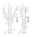
- FIGS. 2A , 2 B and 2 Care top, front and right-side plan drawings, respectively, of an atherectomy head 30 , at rest or low rotational speeds.
- the drive shaft 20may be made from a helically coiled wire, terminating at a distal end 21 .
- the distal end 21may be rounded, may be tapered, may be left square, or may include an optional cap that terminates the drive shaft and prevents damage to the vessel being cleaned.
- the distal end 21also includes a hole that can accommodate the guide wire of the atherectomy device.
- the distal end 21may include abrasive material that may be used to start a pilot hole in the blockage, from proximal to distal portions of the blockage.
- the drive shaftmay be made from more than one wire, such as two wires, three wires, five wires, ten wires, fifteen wires, or any other suitable number of wires.
- the wiresare all interwoven in the helical coil.
- the atherectomy head 30includes a pair of arms 31 and 41 that are pivotally attached to the drive shaft at drive shaft anchor points 32 and 42 , respectively, and have free ends 33 and 43 , respectively.
- the anchor points 32 and 42are near the distal end 21 of the drive shaft 20 .
- the arms 31 and 41are mounted so that they may pivot in planes tangential to the drive shaft at drive shaft anchor points 32 and 42 . In other words, if each arm 31 and 41 were to pivot around a line, each line would be perpendicular to the drive shaft rotation axis and would intersect the drive shaft rotation axis.
- the drive shaft anchor points 32 and 42are directly opposite each other on the drive shaft 20 . In other applications, the drive shaft anchor points 32 and 42 are both located on one side of the drive shaft. In some applications, there may be only one arm. In other applications, there may be more than two arms, optionally located equidistantly around the drive shaft. In some of these multi-arm applications, the anchor points are all located the same distance away from the distal end 21 of the drive shaft 20 . In other of these multi-arm applications, one or more of the anchor points is located a different distance away from the distal end 21 of the drive shaft 20 than one or more of the other anchor points.
- the arms 31 and 41have equal masses, so that the combined center of mass of the two arms lies on the rotational axis of the drive shaft. In other applications, the arms 31 and 41 have different masses, so that their combined center of mass is laterally displaced from the rotational axis of the drive shaft. In still other applications, the drive shaft itself may have one or more enlarged portions in the vicinity of the anchor points.
- the arms 31 and 41may be oriented generally parallel to the drive shaft. This generally parallel orientation may help reduce the cross-sectional size of the atherectomy head 30 , so that it may fit within a relatively small catheter 13 during insertion, positioning, and removal.
- the atherectomy head 30may fit with a size 6 or 7 French catheter (i.e., a 2 or 2.33 mm-diameter catheter), although other suitable sizes may be used as well.
- the armsmay include an optional feature to ensure that this rest position lies generally parallel to the drive shaft; such as a spring or other suitable orienting feature.
- using spring-loaded armsmay allow a nearly constant force to be exerted against the wall of the vessel, and may even allow for differential cutting and/or grinding.
- FIGS. 3A , 3 B and 3 Care top, front and right-side plan drawings, respectively, of the atherectomy head 30 of FIGS. 2A , 2 B and 2 C, at high rotational speeds. At these high rotational speeds, the arms 31 and 41 become extended away from the drive shaft 20 . The arm extension may occur due to centrifugal force, or due to any suitable actuating force.
- the free ends 33 and 43 of the arms 31 and 41may include one or more abrading features for cutting at a blockage in the vessel, and one or more abrading features for grinding at a blockage in the vessel.
- the distinction between cutting and grindingmay not be merely academic; the type of abrading may be matched to a particular hardness of blockage material, so that cutting may suit a particular hardness and grinding may suit a different hardness.
- cutting and/or slicingmay be well suited to particularly soft blockage material, while grinding, scraping and/or sanding may be well suited to particularly hard blockage material.
- the free ends 33 and 43 of the arms 31 and 41include cutting edges 34 and 44 , respectively.
- the cutting featuresmay be a blade or multiple blades along one or more edges of the free ends 33 and 43 of the arms 31 and 41 , respectively.
- each blademay include arm material formed with a right angle and/or an acute angle, so that when the drive shaft is rotated in the so-called “cutting direction” 24 , a blade is passed over the blockage and a small portion of the blockage is shaved off.
- cutting directionthe so-called “cutting direction” 24
- removal of the blockagemay require many passes of the blade over the blockage, which may be accomplished in a relatively short amount of time due to the relatively high drive shaft rotation speed.
- the orientation of the cutting edges 34 and 44 on the free ends 33 and 43 of the arms 31 and 41are seen a bit more clearly in several of the following figures, which show the arms 31 and 41 in outstretched or extended positions at relatively high rotation speeds.
- the free ends 33 and 43 of the arms 31 and 41also include grinding edges.
- the grinding edgesmay include abrasive grit or other abrasive material 35 and 45 disposed on an exterior face of the free ends 33 and 43 of the arms 31 and 41 .
- the abrasive materialmay be dragged across the vessel blockage just prior to the grinding edge passing over the blockage, when the drive shaft is rotated in a so-called “grinding direction” 25 , which is in the opposite direction as the “cutting direction” 24 .
- cutting edgesmay be the same physical surfaces as the so-called “grinding edges”, where the blade-like characteristic of the edge may cut when the drive shaft is rotated in the cutting direction, but may simply pass over the blockage material when the drive shaft is rotated in the grinding direction.
- This edgemay be analogous to the blade in a shaver, which provides a close shave when passed over skin in one orientation, but does little when passed over skin in the opposite orientation.
- the so-called “cutting feature”may be the cutting edge itself, and the so-called “grinding feature” may be the abrasive material located on the free end of the arm, adjacent to the cutting edge.
- the so-called “grinding edge”may be the same physical surface as the cutting edge, where, like a razor blade, the edge shaves material off the blockage when passed over the blockage in one orientation (the cutting direction) but has little effect when passed over the blockage in the other orientation (the grinding direction).
- the so-called “grinding”occurs from the abrasive material on the free end of the arm, which may located adjacent to the cutting/grinding edge itself.
- the grinding featuremay be considered to be “on” the grinding edge, even though the grinding feature may be an abrasive material disposed on the free end of the arm, adjacent to the grinding edge and trailing the grinding edge when the drive shaft is rotated in the grinding direction.
- the atherectomy head 30may include optional motion limiters on one or both arms 31 and 41 .
- an optional motion limitermay prevent one or both arms 31 and 41 from extending completely perpendicular to the drive shaft, and may allow movement only to a particular angle, such as 45 degrees, 60 degrees, or any other suitable angle less than 90 degrees.
- an optional motion limitermay allow movement of one or both arms 31 and 41 to only one side of the drive shaft, thereby ensuring that arm 31 moves “up” and arm 41 moves “down”, as in FIG. 3 .
- the optional motion limitersmay be included with the anchor points, the drive shaft, or the arms themselves.
- the arms 31 and 41each include a scoop-like shape to the free end, where the scoop includes abrasive material on its outer surface and has a sharpened edge that acts as a blade-like structure when the drive shaft is rotated in the cutting direction.
- the scoopsmay be a pair of hemispherical cups that nest together and pivot about an axle at a distance from their distal tips.
- the arms 31 and 41may include a pair or multitude of blades with central pivots the nest together in parallel, where a linkage connects them to a central pivot.
- the arms 31 and 41may include a pair of flat blades similar to scissor blades but with their outer edges sharpened, which pivot about an axle at a distance from their distal tips.
- FIGS. 4 and 5An alternative design for the atherectomy head uses arms that hinge to the drive shaft and can expand radially outward during high drive shaft rotational speeds, rather than arms that pivot as in FIGS. 2 and 3 . These hinged arms are shown in FIGS. 4 and 5 .
- FIGS. 4A , 4 B and 4 Care top, front and right-side plan drawings, respectively, of an atherectomy head 50 , at rest or low rotational speeds.
- FIGS. 5A , 5 B and 5 Care top, front and right-side plan drawings, respectively, of the atherectomy head 50 of FIGS. 4A , 4 B and 4 C, at high rotational speeds.
- the atherectomy head 50includes a pair of arms 51 and 61 that are hingedly attached to the drive shaft at hinges 52 and 62 , respectively, and have free ends 53 and 63 , respectively.
- the hinges 52 and 62are near the distal end 21 of the drive shaft 20 .
- the arms 51 and 61are mounted so that they may move in a plane that includes the rotational axis of the drive shaft.
- the hinges 52 and 62are directly opposite each other on the drive shaft 20 .
- the drive shaft anchor points 52 and 62are both located on one side of the drive shaft.
- the anchor pointsare all located the same distance away from the distal end 21 of the drive shaft 20 .
- one or more of the anchor pointsis located a different distance away from the distal end 21 of the drive shaft 20 than one or more of the other anchor points.
- the arms 51 and 61have equal masses, so that the combined center of mass of the two arms lies on the rotational axis of the drive shaft. In other applications, the arms 51 and 61 have different masses, so that their combined center of mass is laterally displaced from the rotational axis of the drive shaft. In still other applications, the drive shaft itself may have one or more enlarged portions in the vicinity of the anchor points.
- the arms 51 and 61may be oriented generally parallel to the drive shaft.
- the armsmay include an optional feature to ensure that this rest position lies generally parallel to the drive shaft; such as a spring or other suitable orienting feature.
- This generally parallel orientationmay help reduce the cross-sectional size of the atherectomy head 50 , so that it may fit within a relatively small catheter 13 during insertion, positioning, and removal.
- the atherectomy head 50may fit with a size 6 or 7 French catheter (i.e., a 2 or 2.33 mm-diameter catheter), although other suitable sizes may be used as well.
- the arms 51 and 61become extended away from the drive shaft 20 .
- the arm extensionmay occur due to centrifugal force, or due to any suitable actuating force.
- the free ends 53 and 63 of the arms 51 and 61may include one or more abrading features for cutting at a blockage in the vessel, and one or more abrading features for grinding at a blockage in the vessel.
- the free ends 53 and 63 of the arms 51 and 61include cutting edges 54 and 64 , respectively.
- the cutting featuresmay be a blade or multiple blades along one or more edges of the free ends 53 and 63 of the arms 51 and 61 , respectively.
- each blademay include arm material formed with a right angle and/or an acute angle, so that when the drive shaft is rotated in the so-called “cutting direction” 24 , a blade is passed over the blockage and a small portion of the blockage is shaved off.
- cutting directionthe so-called “cutting direction” 24
- removal of the blockagemay require many passes of the blade over the blockage, which may be accomplished in a relatively short amount of time due to the relatively high drive shaft rotation speed.
- the orientation of the cutting edges 54 and 64 on the free ends 53 and 63 of the arms 51 and 61are seen a bit more clearly in several of the following figures, which show the arms 51 and 61 in outstretched or extended positions at relatively high rotation speeds.
- the free ends 53 and 63 of the arms 51 and 61also include grinding edges.
- the grinding edgesmay include abrasive grit or other abrasive material 55 and 65 disposed on an exterior face of the free ends 53 and 63 of the arms 51 and 61 .
- the abrasive materialmay be dragged across the vessel blockage just prior to the grinding edge passing over the blockage, when the drive shaft is rotated in a so-called “grinding direction” 25 , which is in the opposite direction as the “cutting direction” 24 .
- cutting edgesmay be the same physical surfaces as the so-called “grinding edges”, where the blade-like characteristic of the edge may cut when the drive shaft is rotated in the cutting direction, but may simply pass over the blockage material when the drive shaft is rotated in the grinding direction.
- This edgemay be analogous to the blade in a shaver, which provides a close shave when passed over skin in one orientation, but does little when passed over skin in the opposite orientation.
- the so-called “cutting feature”may be the cutting edge itself, and the so-called “grinding feature” may be the abrasive material located on the free end of the arm, adjacent to the cutting edge.
- the so-called “grinding edge”may be the same physical surface as the cutting edge, where, like a razor blade, the edge shaves material off the blockage when passed over the blockage in one orientation (the cutting direction) but has little effect when passed over the blockage in the other orientation (the grinding direction).
- the so-called “grinding”occurs from the abrasive material on the free end of the arm, which may located adjacent to the cutting/grinding edge itself.
- the grinding featuremay be considered to be “on” the grinding edge, even though the grinding feature may be an abrasive material disposed on the free end of the arm, adjacent to the grinding edge and trailing the grinding edge when the drive shaft is rotated in the grinding direction.
- the atherectomy head 50may include optional motion limiters on one or both arms 51 and 61 .
- an optional motion limitermay prevent one or both arms 51 and 61 from extending completely perpendicular to the drive shaft, and may allow movement only to a particular angle, such as 45 degrees, 60 degrees, or any other suitable angle less than 90 degrees.
- the optional motion limitersmay be included with the hinges, the drive shaft, or the arms themselves.
- the atherectomy head 30implicitly assumes that the arms 31 and 41 extend in only one direction away from the drive shaft, so that the arms 31 and 41 “lead” the drive shaft anchor points 32 and 42 when the drive shaft is rotated in the cutting direction 24 , and “trail” the drive shaft anchor points 32 and 42 when the drive shaft is rotated in the grinding direction 25 .
- FIG. 6is a plan drawing of an atherectomy head 70 with the drive shaft rotating in the cutting direction 24 , viewed from the distal end 21 of the drive shaft
- FIG. 7is a plan drawing of the atherectomy head 70 of FIG. 6 , with the drive shaft rotating in the grinding direction 25 , viewed from the distal end 21 of the drive shaft.
- the head 70has arms 71 and 81 with free ends 73 and 83 having cutting features 74 and 84 and grinding features 75 and 85 ; all are analogous in function to the features of FIGS. 2 and 3 .
- FIGS. 8A , 8 B and 8 Care top, front and right-side plan drawings, respectively, of an atherectomy head 100 , at relatively high rotational speeds.
- the atherectomy head 100is typically moved through a patient's vasculature within a catheter 101 , so that the head and drive shaft 102 do not cause any damage to the vessels during insertion or extraction.
- the catheter 101is shown in the figures, and it will be understood that similar-functioning catheters may also be used with the head designs of FIGS. 2-5 .
- the drive shaft 102has a proximal end located at or near the operator, external to the patient's body, and a distal end 104 that extends to or near the end of the catheter 101 .
- the drive shaft 102includes one or more helically coiled wires, although any suitable torque-transmitting structure may be used.
- the distal end 104 of the drive shaftincludes a hole that can accommodate a guide wire (not shown).
- the drive shaft 102may include an optional taper 103 that reduces the diameter of the helical coils in the vicinity of the distal end 104 . The function of this optional taper 103 is described below.
- the distal end 104 of the drive shaft 102includes a pair of hinges 105 A and 105 B that pivotally connect two arms 106 A and 106 B to the drive shaft 102 .
- the arms 106 A and 106 Bare mounted so that they may pivot in planes tangential to the drive shaft at hinges 105 A and 105 B. In other words, if each arm 106 A and 106 B were to pivot around a line, each line would be perpendicular to the drive shaft rotation axis and would intersect the drive shaft rotation axis.
- two hinges 105 A and 105 Bare used at the distal end 104 of the drive shaft 102 , and these hinges 105 A and 105 B are disposed on the exterior of the drive shaft 102 , so that the interior of the drive shaft 102 may remain hollow and may accommodate a guide wire.
- a single hingemay be used, which extends through the center of the drive shaft.
- each arm 106 A and 106 Battaches at a hinge 107 A and 107 B to an abrasive element 108 A and 108 B.
- Each abrasive element 108 A and 108 Bincludes a cutting element 109 A and 109 B, which may cut, slice and/or scrape away a blockage when the drive shaft 102 is rotated in the “cutting” direction 24 .
- the cutting element 109 A and 109 Bmay be an edge of the abrasive element 108 A and 108 B, which may subtend an acute angle in cross-section.
- the cutting elementmay be an actual blade that is attached to the abrasive element.
- Each abrasive element 108 A and 108 Balso includes a grinding element 110 A and 110 B, which may grind or sand away a blockage when the drive shaft 102 is rotated in the “grinding” direction 25 .
- the grinding element 110 A and 110 Bmay be an abrasive material disposed on the abrasive element 108 A and 108 B adjacent to and leading the cutting element 109 A and 109 B when the drive shaft 102 is rotated in the “grinding” direction 25 .
- leadingmeans that when the drive shaft 102 is rotated in the “grinding” direction 25 , the grinding element 110 A or 110 B passes a particular point on the vessel just before the cutting element 109 A or 109 B.
- the grinding element 110 A or 110 Bpasses a particular point on the vessel just after the cutting element 109 A or 109 B, and the grinding element is said to be trailing the cutting element when the drive shaft is rotated in the “cutting” direction 24 .
- a single pass of the grinding or cutting elements over a blockageremoves very little material from the blockage. Many passes are typically required to remove the full blockage. Because the drive shaft may be rotated very rapidly, typically over 100,000 revolutions per minute, many passes may be made in a reasonable amount of time.
- the arms 106 A and 106 B and the abrasive elements 108 A and 108 Bare forced radially outward when the drive shaft 102 is rotated at high speeds, in either direction. Such a force may arise from centrifugal force, and/or may arise from an external force delivered through the arms 106 A and 106 B.
- each abrasive element 108 A and 108 Bhas a largely planar face that contacts the blockage or the vessel wall. This face may be truly planar, or may have a slight curvature. In some applications, the face may be cylindrical, with a cylindrical axis that is parallel to the rotational axis of the drive shaft 102 . In some applications, each cutting element 109 A and 109 B may be straight, or linear. In some applications, the face may be slightly convex along one dimension or along both dimensions.
- each abrasive element 108 A and 108 Bconnects to the respective arm 106 A and 106 B ensures that the largely planar face of the abrasive elements makes contact with the blockage or the vessel wall in at least two places. In some applications, such a geometry may reduce incidental damage to the vessel wall.
- the arms 106 A and 106 B and the abrasive elements 108 A and 108 Bare folded together to lie near the rotational axis of the drive shaft 102 .
- these elementsmay have a relatively compact cross-section, and may fit inside the catheter 101 .
- the optional taper 103 in the drive shaftmay be used to accommodate all or a portion of the abrasive elements 108 A and 108 B to ensure that the abrasive elements 108 A and 108 B do indeed fit within the catheter 101 .
- the cathetermay be used to position the abrasive elements at or near the blockage in the vessel. Once the device has been properly positioned, the drive shaft 102 is advanced past the distal end of the catheter 101 , and/or the catheter 101 is retracted past the distal end of the abrasive elements 108 A and 108 B. This exposes the abrasive elements 108 A and 108 B to the blockage and/or the inside of the vessel.
- an optional springmay force the arms 106 A and 106 B apart from each other and away from the rotational axis of the drive shaft 102 .
- a springmay be a compression spring that acts on one or both of the arms 106 A and 106 B, and/or may a torsional spring that acts through one or both hinges 105 A and 105 B to drive the arms 106 A and 106 B apart.
- the spring or springsmay be omitted, so that the arms 106 A and 106 B are not explicitly driven apart at low drive shaft rotational speeds or at rest.
- the abrasive elements 108 A and 108 Bmay be driven apart only by centrifugal force, which forces them against the vessel wall and/or the blockage.
- biasing springsthat force the arms 106 A and 106 B together, toward the rotational axis of the drive shaft, rather than force them apart. Such a biasing force may ensure that the arms 106 A and 106 B return to a folded position when the drive shaft rotation is completed, so that the abrasive elements 108 A and 108 B may be retracted into the catheter and may be easily removed from the vessel.
- more or fewer than two arms 106 , hinges 105 and abrasive elements 108may be used.
- the atherectomy device disclosed hereinhas two important characteristics: (1) the atherectomy head is radially expandable beyond its rest size, and (2) the atherectomy head may be used for blockages having different hardness properties.
- the expandabilityarises from one or more arms on the head, each of which may extend away from the rotational axis of the drive shaft under the influence of centrifugal force and/or an external force applied to the arms.
- the effectiveness for different hardness blockagesarises from having both a cutting element, which can remove soft blockage material, and a grinding element, which can remove hard blockage material.
- the drive shaftmay be rotated in a “cutting” direction, thereby engaging the cutting element, or may be rotated in the opposite direction, known as a “grinding” direction, thereby engaging the grinding element.
- the cutting elementmay be an edge on an abrasive element, which may subtend an acute angle in cross-section and may therefore act like a blade.
- the grinding elementmay be an abrasive material disposed on the abrasive element adjacent to the cutting element, which may “lead” the cutting element when the drive shaft is rotated in the “grinding” direction. At a sufficiently high rotational velocity, centrifugal force may drive the one or more arms radially outward.
- the exact value for “sufficiently high” rotational velocityvaries greatly from design to design, but the criterion for “sufficiently high” may be the rotational velocity at which centrifugal force is sufficient to force the one or more arms radially outward beyond the rest size of the atherectomy head.
- the atherectomy deviceuses a motor to rotate the drive shaft 20 , which can operate in both directions.
- the motorrotates the drive shaft with the same rotational velocity in both the cutting and grinding directions.
- the motorrotates the drive shaft with different rotational velocities in the cutting and grinding directions.
- the rotation of the drive shaftis carried out by the user, rather than a motor.
- the usermay use a handle to rotate the drive shaft, or may optionally use a crank or other adapter to increase torque and/or increase the RPM of the user-initiated drive shaft rotation.
- the atherectomy deviceincludes a valve that removes the debris that comes from the vessel wall.
- a valvemay use a “trap door” or other suitable mechanism to trap the debris particles, and the device may use suitable plumbing to direct the trapped debris particles through the catheter and out of the vessel.
- suitable plumbingmay be desirable, so that the debris particles do not cause vessel blockages downstream in smaller vessels.
Landscapes
- Health & Medical Sciences (AREA)
- Surgery (AREA)
- Life Sciences & Earth Sciences (AREA)
- Biomedical Technology (AREA)
- Nuclear Medicine, Radiotherapy & Molecular Imaging (AREA)
- Engineering & Computer Science (AREA)
- Vascular Medicine (AREA)
- Heart & Thoracic Surgery (AREA)
- Medical Informatics (AREA)
- Molecular Biology (AREA)
- Animal Behavior & Ethology (AREA)
- General Health & Medical Sciences (AREA)
- Public Health (AREA)
- Veterinary Medicine (AREA)
- Surgical Instruments (AREA)
Abstract
Description
Claims (27)
Priority Applications (8)
| Application Number | Priority Date | Filing Date | Title |
|---|---|---|---|
| US12/466,130US9186170B2 (en) | 2008-06-05 | 2009-05-14 | Bidirectional expandable head for rotational atherectomy device |
| CA2722317ACA2722317C (en) | 2008-06-05 | 2009-05-18 | Bidirectional expandable head for rotational atherectomy device |
| CN200980120662.XACN102056558B (en) | 2008-06-05 | 2009-05-18 | Bidirectional expandable head for rotational atherectomy device |
| AU2009255433AAU2009255433B2 (en) | 2008-06-05 | 2009-05-18 | Bidirectional expandable head for rotational atherectomy device |
| JP2011512517AJP5285768B2 (en) | 2008-06-05 | 2009-05-18 | Bidirectional expandable head for rotary atherectomy device |
| ES09758966.7TES2594707T3 (en) | 2008-06-05 | 2009-05-18 | Bi-directional expandable head for Rotational Atherectomy device |
| EP09758966.7AEP2280657B1 (en) | 2008-06-05 | 2009-05-18 | Bidirectional expandable head for rotational atherectomy device |
| PCT/US2009/044299WO2009148805A1 (en) | 2008-06-05 | 2009-05-18 | Bidirectional expandable head for rotational atherectomy device |
Applications Claiming Priority (2)
| Application Number | Priority Date | Filing Date | Title |
|---|---|---|---|
| US5896208P | 2008-06-05 | 2008-06-05 | |
| US12/466,130US9186170B2 (en) | 2008-06-05 | 2009-05-14 | Bidirectional expandable head for rotational atherectomy device |
Publications (2)
| Publication Number | Publication Date |
|---|---|
| US20090306689A1 US20090306689A1 (en) | 2009-12-10 |
| US9186170B2true US9186170B2 (en) | 2015-11-17 |
Family
ID=41398433
Family Applications (1)
| Application Number | Title | Priority Date | Filing Date |
|---|---|---|---|
| US12/466,130Expired - Fee RelatedUS9186170B2 (en) | 2008-06-05 | 2009-05-14 | Bidirectional expandable head for rotational atherectomy device |
Country Status (8)
| Country | Link |
|---|---|
| US (1) | US9186170B2 (en) |
| EP (1) | EP2280657B1 (en) |
| JP (1) | JP5285768B2 (en) |
| CN (1) | CN102056558B (en) |
| AU (1) | AU2009255433B2 (en) |
| CA (1) | CA2722317C (en) |
| ES (1) | ES2594707T3 (en) |
| WO (1) | WO2009148805A1 (en) |
Cited By (4)
| Publication number | Priority date | Publication date | Assignee | Title |
|---|---|---|---|---|
| US10869689B2 (en) | 2017-05-03 | 2020-12-22 | Medtronic Vascular, Inc. | Tissue-removing catheter |
| US11357534B2 (en) | 2018-11-16 | 2022-06-14 | Medtronic Vascular, Inc. | Catheter |
| US11690645B2 (en) | 2017-05-03 | 2023-07-04 | Medtronic Vascular, Inc. | Tissue-removing catheter |
| US11819236B2 (en) | 2019-05-17 | 2023-11-21 | Medtronic Vascular, Inc. | Tissue-removing catheter |
Families Citing this family (51)
| Publication number | Priority date | Publication date | Assignee | Title |
|---|---|---|---|---|
| US7708749B2 (en) | 2000-12-20 | 2010-05-04 | Fox Hollow Technologies, Inc. | Debulking catheters and methods |
| US7713279B2 (en) | 2000-12-20 | 2010-05-11 | Fox Hollow Technologies, Inc. | Method and devices for cutting tissue |
| US6299622B1 (en) | 1999-08-19 | 2001-10-09 | Fox Hollow Technologies, Inc. | Atherectomy catheter with aligned imager |
| US8328829B2 (en) | 1999-08-19 | 2012-12-11 | Covidien Lp | High capacity debulking catheter with razor edge cutting window |
| JP4080874B2 (en) | 2000-12-20 | 2008-04-23 | フォックス ハロウ テクノロジーズ,インコーポレイティド | Bulking catheter |
| EP2335660B1 (en) | 2001-01-18 | 2018-03-28 | The Regents of The University of California | Minimally invasive glaucoma surgical instrument |
| US8246640B2 (en) | 2003-04-22 | 2012-08-21 | Tyco Healthcare Group Lp | Methods and devices for cutting tissue at a vascular location |
| US20060241580A1 (en) | 2003-06-10 | 2006-10-26 | Neomedix Corporation | Device and methods useable for treatment of glaucoma and other surgical procedures |
| US20070276419A1 (en) | 2006-05-26 | 2007-11-29 | Fox Hollow Technologies, Inc. | Methods and devices for rotating an active element and an energy emitter on a catheter |
| US8784440B2 (en) | 2008-02-25 | 2014-07-22 | Covidien Lp | Methods and devices for cutting tissue |
| US8414604B2 (en) | 2008-10-13 | 2013-04-09 | Covidien Lp | Devices and methods for manipulating a catheter shaft |
| CN102625673B (en) | 2009-04-29 | 2014-12-24 | 泰科保健集团有限合伙公司 | Methods and devices for cutting and abrading tissue |
| WO2010132748A1 (en) | 2009-05-14 | 2010-11-18 | Fox Hollow Technologies, Inc. | Easily cleaned atherectomy catheters and methods of use |
| WO2011068932A1 (en) | 2009-12-02 | 2011-06-09 | Fox Hollow Technologies, Inc. | Methods and devices for cutting tissue |
| CN102695463B (en) | 2009-12-11 | 2015-01-14 | 泰科保健集团有限合伙公司 | Material removal device having improved material capture efficiency and methods of use |
| RU2538174C2 (en) | 2010-06-14 | 2015-01-10 | Ковидиен Лп | Device for material removal |
| CA2815186C (en) | 2010-10-28 | 2015-12-29 | Covidien Lp | Material removal device and method of use |
| KR20150020240A (en) | 2010-11-11 | 2015-02-25 | 코비디엔 엘피 | Flexible debulking catheters with imaging and methods of use and manufacture |
| EP2750862B1 (en) | 2011-09-01 | 2016-07-06 | Covidien LP | Catheter with helical drive shaft and methods of manufacture |
| US10327947B2 (en) | 2012-04-24 | 2019-06-25 | The Regents Of The University Of Colorado, A Body Corporate | Modified dual-blade cutting system |
| US10682254B2 (en) | 2012-04-24 | 2020-06-16 | The Regents Of The University Of Colorado, A Body Corporate | Intraocular device for dual incisions |
| US9872799B2 (en) | 2012-04-24 | 2018-01-23 | The Regents Of The University Of Colorado, A Body Corporate | Intraocular device for dual incisions |
| US9532844B2 (en) | 2012-09-13 | 2017-01-03 | Covidien Lp | Cleaning device for medical instrument and method of use |
| US9943329B2 (en) | 2012-11-08 | 2018-04-17 | Covidien Lp | Tissue-removing catheter with rotatable cutter |
| US9750525B2 (en)* | 2013-03-14 | 2017-09-05 | Cardiovascular Systems, Inc. | Devices, systems and methods for an oscillating crown drive for rotational atherectomy |
| US20150080795A1 (en) | 2013-07-26 | 2015-03-19 | Cardiovascular Systems, Inc. | Devices, systems and methods for performing atherectomy and subsequent balloon angioplasty without exchanging devices |
| US9155527B2 (en) | 2013-08-22 | 2015-10-13 | Transmed7, Llc | Soft tissue coring biopsy devices and methods |
| EP3043719B1 (en) | 2013-09-12 | 2022-04-13 | Transmed7, LLC | Tissue coring biopsy devices |
| EP3116417B1 (en) | 2014-03-12 | 2021-09-08 | Boston Scientific Limited | Infusion lubricated atherectomy catheter |
| WO2015200702A1 (en) | 2014-06-27 | 2015-12-30 | Covidien Lp | Cleaning device for catheter and catheter including the same |
| US10702300B2 (en) | 2014-07-18 | 2020-07-07 | Cardiovascular Systems, Inc. | Methods, devices and systems for slow rotation of drive shaft driven atherectomy systems |
| US10405878B2 (en) | 2014-07-25 | 2019-09-10 | Boston Scientific Scimed, Inc. | Rotatable medical device |
| US10231750B2 (en) | 2014-09-29 | 2019-03-19 | Transmed7, Llc | Excisional device distal working end actuation mechanism and method |
| EP3017775A1 (en)* | 2014-11-07 | 2016-05-11 | National University of Ireland, Galway | A thrombectomy device |
| US10405879B2 (en) | 2014-12-04 | 2019-09-10 | Boston Scientific Scimed, Inc. | Rotatable medical device |
| EP3240493B1 (en)* | 2014-12-30 | 2020-02-26 | Bard Peripheral Vascular | Abrasive elements for rotational atherectormy systems |
| WO2016115433A1 (en)* | 2015-01-17 | 2016-07-21 | Transmed7, Llc | Excisional device distal working end actuation mechanism and method |
| US10299820B2 (en) | 2015-02-20 | 2019-05-28 | Cardiovascular Systems, Inc. | Methods and systems for disrupting calcified walls of biological conduits and calcified lesions therein |
| US10314667B2 (en) | 2015-03-25 | 2019-06-11 | Covidien Lp | Cleaning device for cleaning medical instrument |
| US10292721B2 (en) | 2015-07-20 | 2019-05-21 | Covidien Lp | Tissue-removing catheter including movable distal tip |
| US10314664B2 (en) | 2015-10-07 | 2019-06-11 | Covidien Lp | Tissue-removing catheter and tissue-removing element with depth stop |
| US10213342B2 (en) | 2015-12-23 | 2019-02-26 | The Regents Of The University Of Colorado, A Body Corporate | Ophthalmic knife and methods of use |
| US10779991B2 (en) | 2015-12-23 | 2020-09-22 | The Regents of the University of Colorado, a body corporated | Ophthalmic knife and methods of use |
| EP3582728A4 (en) | 2017-02-16 | 2020-11-25 | Microsurgical Technology, Inc. | Devices, systems and methods for minimally invasive glaucoma surgery |
| EP3745970B1 (en)* | 2018-03-06 | 2023-08-23 | Viant AS&O Holdings, LLC | Expandable reamer cutting head |
| US10993737B2 (en) | 2018-05-23 | 2021-05-04 | Transmed7, Llc | Excisional devices and methods |
| EP3787522B1 (en)* | 2019-05-23 | 2024-01-10 | Transmed7, LLC | Excisional devices |
| CN111012448A (en)* | 2019-08-20 | 2020-04-17 | 上海微创医疗器械(集团)有限公司 | rotational atherectomy device |
| JP7042861B2 (en)* | 2020-03-23 | 2022-03-28 | バード・ペリフェラル・バスキュラー・インコーポレーテッド | Abrasive elements for rotary atherectomy system |
| US20240415534A1 (en) | 2021-11-03 | 2024-12-19 | Clearstream Technologies Limited | A rotational atherectomy device |
| WO2023177761A2 (en) | 2022-03-16 | 2023-09-21 | Sight Sciences, Inc. | Devices and methods for intraocular tissue manipulation |
Citations (34)
| Publication number | Priority date | Publication date | Assignee | Title |
|---|---|---|---|---|
| US4043323A (en)* | 1974-12-27 | 1977-08-23 | Olympus Optical Co., Ltd. | Medical instrument attached to an endoscope |
| US4895560A (en) | 1988-03-31 | 1990-01-23 | Papantonakos Apostolos C | Angioplasty apparatus |
| US5030201A (en) | 1989-11-24 | 1991-07-09 | Aubrey Palestrant | Expandable atherectomy catheter device |
| US5041124A (en) | 1989-07-14 | 1991-08-20 | Kensey Nash Corporation | Apparatus and method for sclerosing of body tissue |
| US5100425A (en) | 1989-09-14 | 1992-03-31 | Medintec R&D Limited Partnership | Expandable transluminal atherectomy catheter system and method for the treatment of arterial stenoses |
| US5158564A (en) | 1990-02-14 | 1992-10-27 | Angiomed Ag | Atherectomy apparatus |
| US5192291A (en) | 1992-01-13 | 1993-03-09 | Interventional Technologies, Inc. | Rotationally expandable atherectomy cutter assembly |
| US5224945A (en) | 1992-01-13 | 1993-07-06 | Interventional Technologies, Inc. | Compressible/expandable atherectomy cutter |
| US5242461A (en)* | 1991-07-22 | 1993-09-07 | Dow Corning Wright | Variable diameter rotating recanalization catheter and surgical method |
| US5308354A (en) | 1991-07-15 | 1994-05-03 | Zacca Nadim M | Atherectomy and angioplasty method and apparatus |
| US5318576A (en) | 1992-12-16 | 1994-06-07 | Plassche Jr Walter M | Endovascular surgery systems |
| US5376100A (en) | 1991-12-23 | 1994-12-27 | Lefebvre; Jean-Marie | Rotary atherectomy or thrombectomy device with centrifugal transversal expansion |
| US5728123A (en) | 1995-04-26 | 1998-03-17 | Lemelson; Jerome H. | Balloon actuated catheter |
| US5766192A (en) | 1995-10-20 | 1998-06-16 | Zacca; Nadim M. | Atherectomy, angioplasty and stent method and apparatus |
| US5817095A (en) | 1996-02-22 | 1998-10-06 | Smith & Nephew, Inc. | Undercutting surgical instrument |
| US5833650A (en) | 1995-06-05 | 1998-11-10 | Percusurge, Inc. | Catheter apparatus and method for treating occluded vessels |
| US6096054A (en) | 1998-03-05 | 2000-08-01 | Scimed Life Systems, Inc. | Expandable atherectomy burr and method of ablating an occlusion from a patient's blood vessel |
| US6132444A (en)* | 1997-08-14 | 2000-10-17 | Shturman Cardiology Systems, Inc. | Eccentric drive shaft for atherectomy device and method for manufacture |
| US20020026145A1 (en) | 1997-03-06 | 2002-02-28 | Bagaoisan Celso J. | Method and apparatus for emboli containment |
| US20020052638A1 (en) | 1996-05-20 | 2002-05-02 | Gholam-Reza Zadno-Azizi | Method and apparatus for emboli containment |
| US20020077638A1 (en) | 2000-12-19 | 2002-06-20 | Scimed Life Systems, Inc. | Expandable atherectomy burr |
| WO2002062226A1 (en) | 2001-02-05 | 2002-08-15 | Tyco Healthcare Group Lp | Biopsy apparatus and method |
| US6503261B1 (en)* | 2001-01-17 | 2003-01-07 | Scimed Life Systems, Inc. | Bi-directional atherectomy burr |
| US6565588B1 (en) | 2000-04-05 | 2003-05-20 | Pathway Medical Technologies, Inc. | Intralumenal material removal using an expandable cutting device |
| US6596005B1 (en) | 1998-03-05 | 2003-07-22 | Scimed Life Systems, Inc. | Steerable ablation burr |
| JP2003290239A (en) | 2002-03-29 | 2003-10-14 | Masayuki Nakao | Medical treatment appliance |
| US6726690B2 (en) | 2002-01-17 | 2004-04-27 | Concept Matrix, Llc | Diskectomy instrument and method |
| US6800085B2 (en) | 1997-02-28 | 2004-10-05 | Lumend, Inc. | Methods and apparatus for treating vascular occlusions |
| US6800083B2 (en)* | 2001-04-09 | 2004-10-05 | Scimed Life Systems, Inc. | Compressible atherectomy burr |
| US6818001B2 (en) | 2000-04-05 | 2004-11-16 | Pathway Medical Technologies, Inc. | Intralumenal material removal systems and methods |
| US20050277971A1 (en)* | 2004-06-15 | 2005-12-15 | Melkent Anthony J | Minimally invasive instruments and methods for preparing vertebral endplates |
| US20060200191A1 (en) | 1996-05-20 | 2006-09-07 | Gholam-Reza Zadno-Azizi | Method and apparatuses for treating an intravascular occlusion |
| US7303531B2 (en)* | 1998-09-03 | 2007-12-04 | Rubicor Medical, Inc. | Excisional biopsy devices and methods |
| US7344546B2 (en) | 2000-04-05 | 2008-03-18 | Pathway Medical Technologies | Intralumenal material removal using a cutting device for differential cutting |
Family Cites Families (5)
| Publication number | Priority date | Publication date | Assignee | Title |
|---|---|---|---|---|
| JPH04114641A (en)* | 1990-09-04 | 1992-04-15 | Disco Abrasive Syst Ltd | Thrombus remover |
| US5360432A (en) | 1992-10-16 | 1994-11-01 | Shturman Cardiology Systems, Inc. | Abrasive drive shaft device for directional rotational atherectomy |
| WO2000013738A2 (en)* | 1998-09-08 | 2000-03-16 | Lumend, Inc. | Methods and apparatus for treating vascular occlusions |
| US6502361B1 (en)* | 2001-07-30 | 2003-01-07 | Robert A. Hills, Sr. | Rod chairs |
| US7537600B2 (en)* | 2003-06-12 | 2009-05-26 | Boston Scientific Scimed, Inc. | Valved embolic protection filter |
- 2009
- 2009-05-14USUS12/466,130patent/US9186170B2/ennot_activeExpired - Fee Related
- 2009-05-18JPJP2011512517Apatent/JP5285768B2/ennot_activeExpired - Fee Related
- 2009-05-18EPEP09758966.7Apatent/EP2280657B1/ennot_activeNot-in-force
- 2009-05-18CNCN200980120662.XApatent/CN102056558B/ennot_activeExpired - Fee Related
- 2009-05-18WOPCT/US2009/044299patent/WO2009148805A1/enactiveApplication Filing
- 2009-05-18ESES09758966.7Tpatent/ES2594707T3/enactiveActive
- 2009-05-18AUAU2009255433Apatent/AU2009255433B2/ennot_activeCeased
- 2009-05-18CACA2722317Apatent/CA2722317C/ennot_activeExpired - Fee Related
Patent Citations (44)
| Publication number | Priority date | Publication date | Assignee | Title |
|---|---|---|---|---|
| US4043323A (en)* | 1974-12-27 | 1977-08-23 | Olympus Optical Co., Ltd. | Medical instrument attached to an endoscope |
| US4895560A (en) | 1988-03-31 | 1990-01-23 | Papantonakos Apostolos C | Angioplasty apparatus |
| US5041124A (en) | 1989-07-14 | 1991-08-20 | Kensey Nash Corporation | Apparatus and method for sclerosing of body tissue |
| US5100425A (en) | 1989-09-14 | 1992-03-31 | Medintec R&D Limited Partnership | Expandable transluminal atherectomy catheter system and method for the treatment of arterial stenoses |
| US5030201A (en) | 1989-11-24 | 1991-07-09 | Aubrey Palestrant | Expandable atherectomy catheter device |
| US5158564A (en) | 1990-02-14 | 1992-10-27 | Angiomed Ag | Atherectomy apparatus |
| US5308354A (en) | 1991-07-15 | 1994-05-03 | Zacca Nadim M | Atherectomy and angioplasty method and apparatus |
| US5242461A (en)* | 1991-07-22 | 1993-09-07 | Dow Corning Wright | Variable diameter rotating recanalization catheter and surgical method |
| US5376100A (en) | 1991-12-23 | 1994-12-27 | Lefebvre; Jean-Marie | Rotary atherectomy or thrombectomy device with centrifugal transversal expansion |
| US5192291A (en) | 1992-01-13 | 1993-03-09 | Interventional Technologies, Inc. | Rotationally expandable atherectomy cutter assembly |
| US5224945A (en) | 1992-01-13 | 1993-07-06 | Interventional Technologies, Inc. | Compressible/expandable atherectomy cutter |
| US5318576A (en) | 1992-12-16 | 1994-06-07 | Plassche Jr Walter M | Endovascular surgery systems |
| US5728123A (en) | 1995-04-26 | 1998-03-17 | Lemelson; Jerome H. | Balloon actuated catheter |
| US5833650A (en) | 1995-06-05 | 1998-11-10 | Percusurge, Inc. | Catheter apparatus and method for treating occluded vessels |
| US5766192A (en) | 1995-10-20 | 1998-06-16 | Zacca; Nadim M. | Atherectomy, angioplasty and stent method and apparatus |
| US5817095A (en) | 1996-02-22 | 1998-10-06 | Smith & Nephew, Inc. | Undercutting surgical instrument |
| US20060200191A1 (en) | 1996-05-20 | 2006-09-07 | Gholam-Reza Zadno-Azizi | Method and apparatuses for treating an intravascular occlusion |
| US20060200075A1 (en) | 1996-05-20 | 2006-09-07 | Gholam-Reza Zadno-Azizi | Method and apparatus for emboli containment |
| US20060200074A1 (en) | 1996-05-20 | 2006-09-07 | Gholam-Reza Zadno-Azizi | Method and apparatus for emboli containment |
| US20020052638A1 (en) | 1996-05-20 | 2002-05-02 | Gholam-Reza Zadno-Azizi | Method and apparatus for emboli containment |
| US20030208222A1 (en) | 1996-05-20 | 2003-11-06 | Gholam-Reza Zadno-Azizi | Method and apparatus for emboli containment |
| US20040015150A1 (en) | 1996-05-20 | 2004-01-22 | Gholam-Reza Zadno-Azizi | Method and apparatus for emboli containment |
| US6800085B2 (en) | 1997-02-28 | 2004-10-05 | Lumend, Inc. | Methods and apparatus for treating vascular occlusions |
| US20020026145A1 (en) | 1997-03-06 | 2002-02-28 | Bagaoisan Celso J. | Method and apparatus for emboli containment |
| US6132444A (en)* | 1997-08-14 | 2000-10-17 | Shturman Cardiology Systems, Inc. | Eccentric drive shaft for atherectomy device and method for manufacture |
| US20030199889A1 (en) | 1998-03-05 | 2003-10-23 | Scimed Life Systems, Inc. | Ablation burr |
| US20050149084A1 (en)* | 1998-03-05 | 2005-07-07 | Scimed Life Systems, Inc. | Ablation burr |
| US7252674B2 (en) | 1998-03-05 | 2007-08-07 | Boston Scientific Scimed, Inc. | Expandable ablation burr |
| US6096054A (en) | 1998-03-05 | 2000-08-01 | Scimed Life Systems, Inc. | Expandable atherectomy burr and method of ablating an occlusion from a patient's blood vessel |
| US6416526B1 (en) | 1998-03-05 | 2002-07-09 | Scimed Life Systems, Inc. | Expandable atherectomy burr |
| US6685718B1 (en) | 1998-03-05 | 2004-02-03 | Scimed Life Systems, Inc. | Expandable ablation burr |
| US6596005B1 (en) | 1998-03-05 | 2003-07-22 | Scimed Life Systems, Inc. | Steerable ablation burr |
| US7303531B2 (en)* | 1998-09-03 | 2007-12-04 | Rubicor Medical, Inc. | Excisional biopsy devices and methods |
| US6565588B1 (en) | 2000-04-05 | 2003-05-20 | Pathway Medical Technologies, Inc. | Intralumenal material removal using an expandable cutting device |
| US6818001B2 (en) | 2000-04-05 | 2004-11-16 | Pathway Medical Technologies, Inc. | Intralumenal material removal systems and methods |
| US7344546B2 (en) | 2000-04-05 | 2008-03-18 | Pathway Medical Technologies | Intralumenal material removal using a cutting device for differential cutting |
| US20020077638A1 (en) | 2000-12-19 | 2002-06-20 | Scimed Life Systems, Inc. | Expandable atherectomy burr |
| US6436111B1 (en)* | 2000-12-19 | 2002-08-20 | Scimed Life Systems, Inc. | Expandable atherectomy burr |
| US6503261B1 (en)* | 2001-01-17 | 2003-01-07 | Scimed Life Systems, Inc. | Bi-directional atherectomy burr |
| WO2002062226A1 (en) | 2001-02-05 | 2002-08-15 | Tyco Healthcare Group Lp | Biopsy apparatus and method |
| US6800083B2 (en)* | 2001-04-09 | 2004-10-05 | Scimed Life Systems, Inc. | Compressible atherectomy burr |
| US6726690B2 (en) | 2002-01-17 | 2004-04-27 | Concept Matrix, Llc | Diskectomy instrument and method |
| JP2003290239A (en) | 2002-03-29 | 2003-10-14 | Masayuki Nakao | Medical treatment appliance |
| US20050277971A1 (en)* | 2004-06-15 | 2005-12-15 | Melkent Anthony J | Minimally invasive instruments and methods for preparing vertebral endplates |
Cited By (12)
| Publication number | Priority date | Publication date | Assignee | Title |
|---|---|---|---|---|
| US10869689B2 (en) | 2017-05-03 | 2020-12-22 | Medtronic Vascular, Inc. | Tissue-removing catheter |
| US10925632B2 (en) | 2017-05-03 | 2021-02-23 | Medtronic Vascular, Inc. | Tissue-removing catheter |
| US10987126B2 (en) | 2017-05-03 | 2021-04-27 | Medtronic Vascular, Inc. | Tissue-removing catheter with guidewire isolation liner |
| US11051842B2 (en) | 2017-05-03 | 2021-07-06 | Medtronic Vascular, Inc. | Tissue-removing catheter with guidewire isolation liner |
| US11690645B2 (en) | 2017-05-03 | 2023-07-04 | Medtronic Vascular, Inc. | Tissue-removing catheter |
| US11871958B2 (en) | 2017-05-03 | 2024-01-16 | Medtronic Vascular, Inc. | Tissue-removing catheter with guidewire isolation liner |
| US11896260B2 (en) | 2017-05-03 | 2024-02-13 | Medtronic Vascular, Inc. | Tissue-removing catheter |
| US11986207B2 (en) | 2017-05-03 | 2024-05-21 | Medtronic Vascular, Inc. | Tissue-removing catheter with guidewire isolation liner |
| US12114887B2 (en) | 2017-05-03 | 2024-10-15 | Medtronic Vascular, Inc. | Tissue-removing catheter with guidewire isolation liner |
| US11357534B2 (en) | 2018-11-16 | 2022-06-14 | Medtronic Vascular, Inc. | Catheter |
| US12161359B2 (en) | 2018-11-16 | 2024-12-10 | Medtronic Vascular, Inc. | Catheter |
| US11819236B2 (en) | 2019-05-17 | 2023-11-21 | Medtronic Vascular, Inc. | Tissue-removing catheter |
Also Published As
| Publication number | Publication date |
|---|---|
| ES2594707T3 (en) | 2016-12-22 |
| CN102056558B (en) | 2014-09-10 |
| JP5285768B2 (en) | 2013-09-11 |
| CN102056558A (en) | 2011-05-11 |
| JP2011522597A (en) | 2011-08-04 |
| EP2280657B1 (en) | 2016-07-06 |
| EP2280657A4 (en) | 2013-10-16 |
| CA2722317C (en) | 2016-07-05 |
| AU2009255433B2 (en) | 2014-06-19 |
| US20090306689A1 (en) | 2009-12-10 |
| CA2722317A1 (en) | 2009-12-10 |
| EP2280657A1 (en) | 2011-02-09 |
| AU2009255433A1 (en) | 2009-12-10 |
| WO2009148805A1 (en) | 2009-12-10 |
Similar Documents
| Publication | Publication Date | Title |
|---|---|---|
| US9186170B2 (en) | Bidirectional expandable head for rotational atherectomy device | |
| JP5420645B2 (en) | Polishing nose cone with expandable cutting and polishing area for rotary atherectomy device | |
| CA2518497C (en) | Interventional catheters having differential cutting surfaces | |
| CN104955406B (en) | Rotary atherectomy device with eccentric grinding head | |
| EP2967640B1 (en) | Devices for a piloting tip bushing for rotational atherectomy | |
| US10357275B2 (en) | Dual-basket self-centering rotational device for treatment of arterial occlusive disease with infinitely adjustable cutting size | |
| US20090312777A1 (en) | Atherectomy device supported by fluid bearings | |
| CN112969421A (en) | System, apparatus and method with intermittent dual action (grinding and cutting) forces of continuous immersion and suction | |
| CN106535790A (en) | Method, apparatus and system for slowly rotating drive shaft driven rotary cutting system | |
| US20180256198A1 (en) | Devices, systems and methods for a piloting tip bushing for rotational atherectomy | |
| US9750525B2 (en) | Devices, systems and methods for an oscillating crown drive for rotational atherectomy | |
| CA2961926A1 (en) | Devices, systems and methods for a piloting tip bushing for rotational atherectomy |
Legal Events
| Date | Code | Title | Description |
|---|---|---|---|
| AS | Assignment | Owner name:CARDIOVASCULAR SYSTEMS, INC., MINNESOTA Free format text:ASSIGNMENT OF ASSIGNORS INTEREST;ASSIGNORS:WELTY, RYAN;PLOWE, CHARLES A.;PIIPPO, CASSANDRA A.;AND OTHERS;SIGNING DATES FROM 20090722 TO 20090723;REEL/FRAME:023018/0133 Owner name:CARDIOVASCULAR SYSTEMS, INC., MINNESOTA Free format text:ASSIGNMENT OF ASSIGNORS INTEREST;ASSIGNORS:WELTY, RYAN;PLOWE, CHARLES A.;PIIPPO, CASSANDRA A.;AND OTHERS;REEL/FRAME:023018/0133;SIGNING DATES FROM 20090722 TO 20090723 | |
| AS | Assignment | Owner name:PARTNERS FOR GROWTH III, L.P.,CALIFORNIA Free format text:SECURITY AGREEMENT;ASSIGNOR:CARDIOVASCULAR SYSTEMS, INC.;REEL/FRAME:024233/0346 Effective date:20100412 Owner name:PARTNERS FOR GROWTH III, L.P., CALIFORNIA Free format text:SECURITY AGREEMENT;ASSIGNOR:CARDIOVASCULAR SYSTEMS, INC.;REEL/FRAME:024233/0346 Effective date:20100412 | |
| AS | Assignment | Owner name:CARDIOVASCULAR SYSTEMS, INC., MINNESOTA Free format text:RELEASE BY SECURED PARTY;ASSIGNOR:PARTNERS FOR GROWTH III, L.P.;REEL/FRAME:035678/0128 Effective date:20150427 | |
| STCF | Information on status: patent grant | Free format text:PATENTED CASE | |
| FEPP | Fee payment procedure | Free format text:MAINTENANCE FEE REMINDER MAILED (ORIGINAL EVENT CODE: REM.); ENTITY STATUS OF PATENT OWNER: SMALL ENTITY | |
| LAPS | Lapse for failure to pay maintenance fees | Free format text:PATENT EXPIRED FOR FAILURE TO PAY MAINTENANCE FEES (ORIGINAL EVENT CODE: EXP.); ENTITY STATUS OF PATENT OWNER: SMALL ENTITY | |
| STCH | Information on status: patent discontinuation | Free format text:PATENT EXPIRED DUE TO NONPAYMENT OF MAINTENANCE FEES UNDER 37 CFR 1.362 | |
| FP | Expired due to failure to pay maintenance fee | Effective date:20191117 |