US9183105B2 - Systems and methods for dynamic scan scheduling - Google Patents
Systems and methods for dynamic scan schedulingDownload PDFInfo
- Publication number
- US9183105B2 US9183105B2US13/758,306US201313758306AUS9183105B2US 9183105 B2US9183105 B2US 9183105B2US 201313758306 AUS201313758306 AUS 201313758306AUS 9183105 B2US9183105 B2US 9183105B2
- Authority
- US
- United States
- Prior art keywords
- circuit model
- scheduler
- under test
- attribute
- system under
- Prior art date
- Legal status (The legal status is an assumption and is not a legal conclusion. Google has not performed a legal analysis and makes no representation as to the accuracy of the status listed.)
- Expired - Fee Related, expires
Links
Images


Classifications
- G—PHYSICS
- G06—COMPUTING OR CALCULATING; COUNTING
- G06F—ELECTRIC DIGITAL DATA PROCESSING
- G06F11/00—Error detection; Error correction; Monitoring
- G06F11/22—Detection or location of defective computer hardware by testing during standby operation or during idle time, e.g. start-up testing
- G06F11/26—Functional testing
- G06F11/263—Generation of test inputs, e.g. test vectors, patterns or sequences ; with adaptation of the tested hardware for testability with external testers
- G—PHYSICS
- G01—MEASURING; TESTING
- G01R—MEASURING ELECTRIC VARIABLES; MEASURING MAGNETIC VARIABLES
- G01R31/00—Arrangements for testing electric properties; Arrangements for locating electric faults; Arrangements for electrical testing characterised by what is being tested not provided for elsewhere
- G01R31/28—Testing of electronic circuits, e.g. by signal tracer
- G01R31/317—Testing of digital circuits
- G01R31/3181—Functional testing
- G01R31/3185—Reconfiguring for testing, e.g. LSSD, partitioning
- G01R31/318533—Reconfiguring for testing, e.g. LSSD, partitioning using scanning techniques, e.g. LSSD, Boundary Scan, JTAG
- G01R31/318544—Scanning methods, algorithms and patterns
- G—PHYSICS
- G01—MEASURING; TESTING
- G01R—MEASURING ELECTRIC VARIABLES; MEASURING MAGNETIC VARIABLES
- G01R31/00—Arrangements for testing electric properties; Arrangements for locating electric faults; Arrangements for electrical testing characterised by what is being tested not provided for elsewhere
- G01R31/28—Testing of electronic circuits, e.g. by signal tracer
- G01R31/317—Testing of digital circuits
- G01R31/3181—Functional testing
- G01R31/3185—Reconfiguring for testing, e.g. LSSD, partitioning
- G01R31/318533—Reconfiguring for testing, e.g. LSSD, partitioning using scanning techniques, e.g. LSSD, Boundary Scan, JTAG
- G01R31/318558—Addressing or selecting of subparts of the device under test
- G—PHYSICS
- G06—COMPUTING OR CALCULATING; COUNTING
- G06F—ELECTRIC DIGITAL DATA PROCESSING
- G06F30/00—Computer-aided design [CAD]
- G06F30/30—Circuit design
- G06F30/32—Circuit design at the digital level
- G06F30/333—Design for testability [DFT], e.g. scan chain or built-in self-test [BIST]
- G—PHYSICS
- G01—MEASURING; TESTING
- G01R—MEASURING ELECTRIC VARIABLES; MEASURING MAGNETIC VARIABLES
- G01R31/00—Arrangements for testing electric properties; Arrangements for locating electric faults; Arrangements for electrical testing characterised by what is being tested not provided for elsewhere
- G01R31/28—Testing of electronic circuits, e.g. by signal tracer
- G01R31/317—Testing of digital circuits
- G01R31/3181—Functional testing
- G01R31/3183—Generation of test inputs, e.g. test vectors, patterns or sequences
- G01R31/318307—Generation of test inputs, e.g. test vectors, patterns or sequences computer-aided, e.g. automatic test program generator [ATPG], program translations, test program debugging
- G—PHYSICS
- G01—MEASURING; TESTING
- G01R—MEASURING ELECTRIC VARIABLES; MEASURING MAGNETIC VARIABLES
- G01R31/00—Arrangements for testing electric properties; Arrangements for locating electric faults; Arrangements for electrical testing characterised by what is being tested not provided for elsewhere
- G01R31/28—Testing of electronic circuits, e.g. by signal tracer
- G01R31/317—Testing of digital circuits
- G01R31/3181—Functional testing
- G01R31/3183—Generation of test inputs, e.g. test vectors, patterns or sequences
- G01R31/318342—Generation of test inputs, e.g. test vectors, patterns or sequences by preliminary fault modelling, e.g. analysis, simulation
- G01R31/318357—Simulation
- G06F11/3664—
- G—PHYSICS
- G06—COMPUTING OR CALCULATING; COUNTING
- G06F—ELECTRIC DIGITAL DATA PROCESSING
- G06F11/00—Error detection; Error correction; Monitoring
- G06F11/36—Prevention of errors by analysis, debugging or testing of software
- G06F11/3668—Testing of software
- G06F11/3672—Test management
- G06F11/3688—Test management for test execution, e.g. scheduling of test suites
- G—PHYSICS
- G06—COMPUTING OR CALCULATING; COUNTING
- G06F—ELECTRIC DIGITAL DATA PROCESSING
- G06F11/00—Error detection; Error correction; Monitoring
- G06F11/36—Prevention of errors by analysis, debugging or testing of software
- G06F11/3698—Environments for analysis, debugging or testing of software
- G06F17/5022—
- G06F17/5036—
- G06F17/5045—
- G—PHYSICS
- G06—COMPUTING OR CALCULATING; COUNTING
- G06F—ELECTRIC DIGITAL DATA PROCESSING
- G06F2119/00—Details relating to the type or aim of the analysis or the optimisation
- G06F2119/06—Power analysis or power optimisation
- G—PHYSICS
- G06—COMPUTING OR CALCULATING; COUNTING
- G06F—ELECTRIC DIGITAL DATA PROCESSING
- G06F2119/00—Details relating to the type or aim of the analysis or the optimisation
- G06F2119/08—Thermal analysis or thermal optimisation
- G06F2217/14—
- G06F2217/78—
- G06F2217/80—
- G—PHYSICS
- G06—COMPUTING OR CALCULATING; COUNTING
- G06F—ELECTRIC DIGITAL DATA PROCESSING
- G06F30/00—Computer-aided design [CAD]
- G06F30/30—Circuit design
- G—PHYSICS
- G06—COMPUTING OR CALCULATING; COUNTING
- G06F—ELECTRIC DIGITAL DATA PROCESSING
- G06F30/00—Computer-aided design [CAD]
- G06F30/30—Circuit design
- G06F30/32—Circuit design at the digital level
- G06F30/33—Design verification, e.g. functional simulation or model checking
- G—PHYSICS
- G06—COMPUTING OR CALCULATING; COUNTING
- G06F—ELECTRIC DIGITAL DATA PROCESSING
- G06F30/00—Computer-aided design [CAD]
- G06F30/30—Circuit design
- G06F30/36—Circuit design at the analogue level
- G06F30/367—Design verification, e.g. using simulation, simulation program with integrated circuit emphasis [SPICE], direct methods or relaxation methods
Definitions
- the present inventionrelates to scan scheduling.
- scan patterns to a system under testmay increase stress on the system under test by forcing the system to execute tasks and behave in ways different from the mission mode of the system. This increased stress may cause important power consumption peaks and hot spots due to increased local activity within the system under test that require scan pattern adaptation and retargeting. Scan pattern adaptation and retargeting may also be required due various types of defects, such a process variance, and/or aging of the system that may alter the characteristics of the system under test.
- a computerized systemcomprises a processing module and a scheduler.
- the processing moduleis configured to receive a plurality of scan operations associated with a plurality of segments of a system under test and to generate input test data for the plurality of scan operations to be applied to the system under test.
- the schedulerincludes a circuit model of the system under test defining the plurality of segments.
- the circuit modelmay include at least one attribute providing enhancing information for at least one segment of the plurality of segments.
- the scheduleris adapted to provide the processing module with scheduling for the plurality of scan operations based on the circuit model and to process the at least one attribute to dynamically modify the scheduling.
- the computerized systemmay additionally include an assisting module in communication with the scheduler.
- the scheduleris adapted to provide the at least one attribute to the assisting module for processing.
- the assisting modulemay be adapted to modify the scheduling based at least on the at least one attribute.
- the assisting modulemay be adapted to modify the at least one attribute stored in the circuit module.
- the computerized systemmay have at least one sensor monitoring the system under test and providing status information to the assisting module.
- the at least one sensormay be a power consumption sensor or a thermal sensor.
- the at least one attributemay include floorplan information on a location of the at least one sensor.
- the circuit modelmay include a plurality of attributes for a plurality of nodes of the circuit model and each attribute may denote a power domain to which the node belongs.
- the at least one attributemay include an authorization key.
- a computerized methodcomprises the steps of receiving, at a scheduler, a plurality of access requests for access to a system under test and using a circuit model of the system under test to schedule a plurality of scan operations in response to the plurality of access requests.
- the computerized methodalso includes modifying at least a portion of the scheduled plurality of scan operations based on at least one attribute disposed in the circuit model and detected by the scheduler.
- the computerized methodmay further include generating input test data for testing the system under test based on the modified plurality of scan operations and applying the input test data to the system under test.
- the computerized methodmay also comprise the step of monitoring, through at least one sensor, the system under test and modifying at least the portion of the scheduled plurality of scan operations based on information from the at least one sensor.
- the at least one sensormay be a power consumption sensor or a thermal sensor.
- the at least one attributemay include floorplan information on a location of the at least one sensor.
- the computerized methodmay also comprise modifying the at least one attribute stored in the circuit module.
- the circuit modelmay include a plurality of attributes for a plurality of nodes of the circuit model and each attribute may denote a power domain to which the node belongs.
- a non-transitory, tangible computer-readable medium storing instructions adapted to be executed by a computer processor to perform a methodmay comprise the steps of receiving, at a scheduler, a plurality of access requests for access to a system under test and using a circuit model of the system under test to schedule a plurality of scan operations in response to the plurality of access requests.
- the computerized methodalso includes modifying at least a portion of the scheduled plurality of scan operations based on at least one attribute disposed in the circuit model and detected by the scheduler.
- the computerized methodmay further include generating input test data for testing the system under test based on the modified plurality of scan operations and applying the input test data to the system under test.
- the methodmay further comprise the step of monitoring, through at least one sensor, the system under test and modifying at least the portion of the scheduled plurality of scan operations based on information from the at least one sensor.
- the at least one sensormay be a power consumption sensor or a thermal sensor.
- the methodmay further comprise the step of modifying the at least one attribute stored in the circuit module.
- the circuit modelmay include a plurality of attributes for a plurality of nodes of the circuit model and each attribute may denote a power domain to which the node belongs.
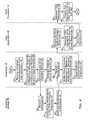
- FIG. 1is a block diagram of a testing environment according to an embodiment
- FIG. 2is a schematic diagram of an embodiment for position-based scheduling in the testing environment of FIG. 1 ;
- FIG. 3is an embodiment of an exemplary circuit model of an exemplary scan chain of the system of FIG. 2 ;
- FIG. 4is an embodiment for position-based scheduling in the testing environment of FIG. 1 ;
- FIG. 5is an embodiment for position-based scheduling in the testing environment of FIG. 1 .
- a testing environment 10 for testing a Joint Test Action Group (JTAG) system 12includes a test instruction set architecture (TISA) processor 14 in communication with the JTAG system 12 via a JTAG test access port (TAP) 16 and a scheduler 18 in communication with the TISA processor 14 .
- the JTAG TAP 16may be, for example, an IEEE 1149.1 TAP or the like.
- TISAtest instruction set architecture
- the software-based algorithmsmay utilize any suitable software programming language (e.g., C; C++, Java, TCL, Python or the like, as well as various combinations thereof) and may be implemented using any suitable processor.
- TISAUse of TISA in a JTAG architecture enables scan operations to be performed at the Scan Segments Level, which allows the definition of independently controllable “scan segments” inside an overall scan path of the JTAG system.
- the TISAis able to perform scan operations on these independently controllable “scan segments” through position-based scheduling resolved at execution time.
- the JTAG system 12may include one or more devices 20 arranged serially within the JTAG system 12 to define a scan chain 22 that is accessible to the TISA processor 14 via the TAP 16 , shown in FIG. 1 .
- the scan chain 22traverses the devices 20 of the JTAG system 12 , which are denoted, in the direction from a Test Data In (TDI) pin of the TAP 16 , shown in FIG. 1 , to a Test Data Out (TDO) pin of the TAP 16 , shown in FIG. 1 , as Device 4, Device 3, Device 2 and Device 1.
- TDITest Data In
- TDOTest Data Out
- Each device 20includes a plurality of registers 24 having elements 26 defining a plurality of instruments 28 . As seen in FIG.
- the JTAG system 12includes eight instruments 28 disposed on the four devices 20 and accessible via the scan chain 22 .
- the eight instruments 28are denoted, in the direction from TDI to TDO, as Instruments 4.2 and 4.1 (which are disposed, in series, on Device 4), Instruments 3.2 and 3.1 (which are disposed, in series, on Device 3), Instrument 2 (which is disposed on Device 2), and Instruments 1.3, 1.2 and 1.1 (which are disposed, in series, on Device 1).
- the eight instruments 28are considered to be separate segments 30 of the JTAG scan chain 22 .
- the segments 30may be controlled individually and, thus, result in scan segment composition 32 (i.e. the scan chain 22 may be considered to be composed of a sequence of eight scan segments 30 which correspond to the eight instruments 28 , rather than being composed of each of the registers 24 of each of the devices 20 of the scan chain 22 ).
- the scan chain 22is composed of a plurality of elements 26 , and each segment 30 includes at least one of the elements 26 of the scan chain 22 .
- the segments 30may be defined at many levels of the JTAG system 12 under test (e.g. segments 30 may be devices 20 , instruments 28 , registers 24 , segments of a register, and the like, as well as various combinations thereof).
- the segments 30 into which the scan chain 22 is decomposedmay be defined at many levels of the JTAG system 12 under test. In this manner, the segment 30 may represent the smallest control unit of the scan chain 22 .
- the TISA processor 14is adapted to execute boundary-scan testing of the JTAG system 12 by combining software-based algorithms with JTAG primitives. More specifically, the TISA processor 14 may perform scan operations at the segment level of JTAG scan chain 22 , which results in the following advantages: (1) the operations on individual segments 30 are local (i.e. they are independent from the topology of which the segment is a part) and (2) an overall scan operation is composed by an ordered series of scan operations on the segments 30 of which the scan chain is composed.
- the scheduler 18is adapted to dynamically schedule the boundary-scan access at the time of execution such that the notion of a “vector” is not necessary. Instead, the scheduler 18 may support position-based scheduling, which requires only the position of each segment 30 inside the scan chain 22 .
- the scheduler 18includes one or more scheduler core processes 34 and a circuit model 36 modeling the JTAG system 12 .
- the scheduler core processes 34are processes configured to perform position-based scheduling using the circuit model 36 , as will be discussed in greater detail below.
- the scheduler 18is configured to receive access requests 38 from one or more user applications 40 , perform position-based scheduling of the access requests 38 using the circuit model 36 , and respond to the user application 40 or to the TISA processor 14 with access responses 42 indicative as to when TISA operations 44 (associated with the access requests 38 and access responses 42 ) may be performed on portions of the scan chain 22 of the JTAG system 12 . Accordingly, a user application 40 needing access to one or more portions of the scan chain 22 , e.g. to one or more particular segments 30 , is configured to provide an access request 38 to the scheduler 18 for the desired segments 30 .
- the scheduler 18is configured to determine a schedule according to which the user application 40 may access the requested portions of the scan chain 22 , thereby obviating the need for the user application 40 to compute the complete vector for the entire scan chain 22 .
- the circuit model 36is a simplified model of the JTAG system 12 that is specified in terms of the scan segments 30 (e.g. Instruments 1.1, 1.2, 1.3, 2, 3.1, 3.2, 4.1 and 4.2) of which the scan chain 22 , shown in FIG. 2 , of JTAG system 12 is composed.
- the circuit model 36may be implemented using a tree structure.
- each segment 30 of the JTAG scan chain 22is represented as a leaf node 46 in the tree structure, and the remainder of the tree includes super-segments (disposed over one or more hierarchical levels) which represent the hierarchical nature of the JTAG scan chain 22 .
- a root node 48 of the tree structurerepresents the JTAG system 12 under test.
- the next level of the circuit model 36include four nodes (denoted as Device 1, Instrument 2, Device 3, and Device 4, where the nodes for Devices 1, 3, and 4 each have additional nodes subtending therefrom and the node for Instrument 2 is a leaf node 46 .
- the bottom level of the circuit model 36includes seven leaf nodes 46 corresponding to the seven segments 30 of which some of the instruments 28 , shown in FIG.
- the Device 1 nodeis a parent to three leaf nodes 46 which represent Instruments 1.1, 1.2, and 1.3 of which Device 1 is composed; the Device 3 node is a parent to two leaf nodes 46 which represent Instruments 3.1 and 3.2 of which Device 3 is composed; and the Device 4 node is a parent to two leaf nodes 46 which represent Instruments 4.1 and 4.2 of which Device 4 is composed).
- the scan segments 30i.e. leaf nodes 46
- the remaining nodesare depicted as oval-shaped nodes.
- the tree structure of the circuit model 36allows each scan segment 30 , i.e. leaf node 46 of the tree structure, to be uniquely identified according to its path in the tree structure.
- the segment 30 that represents Instrument 1.3is uniquely identified by the path SUT.Device1.Instrument1.3.
- the segment 30 that represents Instrument 2is uniquely identified by the path SUT.Instrument2
- the segment 30 that represents Instrument 4.2is uniquely identified by the path SUT.Device4.Instrument4.2, and so forth.
- a simple depth-first (also known as post-order) traversal of the tree structureprovides the correct order of scan segments 30 of the scan chain 22 , shown in FIG. 2 , of JTAG system 12 .
- the circuit model 36is configured to specify the order of the scan segments 30 of the JTAG system 12 (e.g. as depicted in scan segment composition 32 , shown in FIG. 2 ) through the depth-first transversal of the circuit model 36 .
- the circuit model 36may also include one or more attributes 50 attached to one or more nodes of the circuit model 36 that provide enhancing information to the scheduler 18 , shown in FIG. 2 , which the scheduler 18 , shown in FIG. 2 , may use to dynamically adapt the scan operations performed by the TISA processor 14 on the JTAG system 12 , shown in FIG. 2 , to the real scenario being experienced by the JTAG system 12 , shown in FIG. 2 , during testing.
- the attributes 50 of the circuit model 36may include any information suitable for use by scheduler 18 , shown in FIG. 2 , in determining scheduling of access requests 38 , shown in FIG. 2 , and/or access responses 42 , shown in FIG.
- the enhancing information provided by the one or more attributes 50may be related to power consumption peaks and hot spots within the JTAG system 12 , shown in FIG. 2 , due to increased local activity within the JTAG system 12 , shown in FIG. 2 , various other types of defects, such a process variance, and/or aging of the system that may alter the characteristics of the JTAG system 12 when under test or any other similar information.
- This enhancing information provided by the one or more attributes 50may be developed, for example, from a-priori knowledge (e.g.
- attributes 50may instead be provided as additional fields in each node of the circuit model 36 .
- the scheduler 18reads the one or more attributes 50 , shown in FIG. 3 , during transversal of the circuit model 36 and feeds the one or more attributes 50 , shown in FIG. 3 to an assisting module 52 .
- the assisting module 52may be a program running on, or accessible to, the scheduler 18 , while in some embodiments, the assisting module 52 may have some internal state, memory and/or the like.
- the assisting module 52may perform one or more computations using the attributes 50 , shown in FIG. 3 , and may influence the outcome of the transversal, following the Visitor Design Pattern or another similar design pattern.
- the assisting module 52may force a neutral operation rather than the desired operation to reduce activity or can add and/or subtract one or more segments 30 from the scan chain 22 , for example, by modifying value of hierarchy-enabling elements like the Segment Insertion Bit (SIB) from the P1687 standard.
- SIBSegment Insertion Bit
- a traditional scheduleri.e. a scheduler without the assisting module 52
- the assisting module 52may modify one or more of the attributes 50 of the circuit model 36 .
- the circuit model 36may include different types of attributes 50 disposed therein.
- the circuit model 36may include a first type of attributes 50 directed to process variance and a second type of attributes 50 directed to power consumption.
- the systemmay include multiple assisting modules 52 such that each assisting module 52 processes a different type of attribute 50 .
- an embodiment of a method for supporting position-based scheduling for testing JTAG system 12begins at step 54 when the scheduler 18 receives unordered access requests 38 from one or more user applications 40 requesting access to one or more instruments 28 (i.e. segments 30 ), shown in FIG. 2 , of the scan chain 22 , shown in FIG. 2 , of the JTAG system 12 under test.
- the user application 40may issue access requests 38 for any of the instruments 28 , shown in FIG. 2 .
- the user application 40does not have knowledge of the scan segment composition 32 , shown in FIG. 2 , of JTAG system 12 and, therefore, the user application 40 merely sends the scheduler 18 access requests 38 without accounting for the order in which the TISA operations 44 associated with the access requests 38 may be or should be applied to the JTAG system 12 .
- the scheduler 18performs the transversal of the circuit model 36 to determine scheduling of the unordered access requests 38 and to read the one or more attributes 50 .
- the scheduler 18determines scheduling of the unordered access requests 38 based on the scan segment composition 32 , shown in FIG. 2 , as defined in the circuit model 36 of JTAG system 12 under test, which is available to scheduler 18 , as discussed above.
- the scheduler 18sends the one or more attributes to the assisting module 52 for further analysis.
- the scheduler 18then generates ordered access responses 42 based on the transversal of the circuit model 36 at step 60 .
- the assisting module 52receives the one or more attributes 50 from the scheduler 18 at step 62 .
- the assisting module 52computes any modifications that should be made to the ordered access responses 42 using the one or more attributes 50 .
- the assisting module 52sends any modifications to the scheduler 18 .
- the scheduler 18receives the modifications from the assisting module 52 and, at step 70 , modifies the ordered access responses 42 based on any modifications received from the assisting module 52 .
- the scheduler 18sends the modified ordered access responses 42 to the user application 40 .
- the scheduler 18provides modified access responses 42 to user application 40 , where the modified access responses 42 are indicative as to when the user application 40 may provide associated TISA operations 44 (associated with the access requests 38 and access responses 42 ) to TISA processor 14 for execution.
- the user application 40receives the modified ordered access responses 42 from the scheduler 18 and, at step 76 , the user application 40 generates TISA operations 44 associated with the modified ordered access responses 42 to be performed on the scan chain 22 , shown in FIG. 2 , of the JTAG system 12 based on the set of modified ordered access responses 42 .
- the user application 40sends the TISA operations 44 to the TISA processor 14 .
- the TISA processor 14receives the TISA operations 44 .
- the TISA processor 14processes the TISA operations 44 to generate associated input test data and applies the input test data to the JTAG system 12 under test.
- the TISA processor 14may also receive output test data generated by JTAG system 12 .
- the scheduler 18processes a set of the unordered access requests 38 received from user application 40 , generates a set of ordered access responses 42 (e.g. ordered in accordance with scan segment composition 32 , shown in FIG. 2 , as determined by scheduler 18 from circuit model 36 ) and then modifies, through the assisting module 52 , the set of ordered access responses 42 based on enhancing information provided by the attributes 50 .
- a set of ordered access responses 42e.g. ordered in accordance with scan segment composition 32 , shown in FIG. 2 , as determined by scheduler 18 from circuit model 36
- the scheduler 18 and assisting module 52are able to advantageously adapt the set of ordered access responses 42 to more accurately model the JTAG system 12 when testing by modifying the set of ordered access responses 42 to account for various characteristics of the JTAG system 12 such as power consumption characteristics, heat generation characteristics and/or thermal dissipation due to increased local activity within the JTAG system 12 , process variance, aging of the system and/or any other similar characteristics and/or system information.
- this enhancing information provided by the one or more attributes 50may be developed, for example, from a-priori knowledge (e.g. past testing of the JTAG system 12 ), from measurements of the JTAG system 12 when under test or a combination thereof.
- the TISA processor 14may then uses the modified set of ordered access responses 42 for processing of the JTAG system 12 .
- the scheduler 18may be responsible for providing TISA operations 44 to the TISA processor 14 (i.e. the scheduler 18 may perform steps 74 - 78 of FIG. 4 ).
- the assisting module 52may also be incorporated into the scheduler 18 such that the scheduler 18 may be responsible for performing steps 62 - 66 of FIG. 4 .
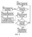
- steps 56 to 70 of FIG. 4may be implemented at the tree transversal level to allow the most direct and efficient application of the Visitor Design Pattern.
- the scheduler 18begins traversal of the circuit model 36 .
- the scheduler 18may begin traversal upon receipt of unordered access requests at step 54 of FIG. 4 .
- the scheduler 18shown in FIG. 4 , evaluates whether an attribute 50 is encountered at a given node of the circuit model 36 during transversal. If an attribute is encountered, the scheduler 18 , shown in FIG.
- the scheduler 18may send the attribute 50 as soon as the scheduler 18 , shown in FIG. 4 , encounters the attribute 50 during the post-order transversal operation.
- the assisting module 52receives the attribute 50 from the scheduler 18 , shown in FIG. 4 .
- the assisting module 52processes the attribute 50 to determine if modifications should be made to the access response 42 for the given node.
- the scheduler 18shown in FIG. 4 , generates the access response 42 for the given node, taking into account any modifications from the assisting module 52 .
- the processing and response given by the assisting module 52 at step 92is advantageously used to directly decide the tree transversal and the generation of access responses 42 by the scheduler 18 , shown in FIG. 4 .
- the scheduler 18shown in FIG. 4 evaluates whether transversal of the circuit model 36 is complete. If transversal is not complete, the scheduler 18 , shown in FIG. 4 , continues transversal, repeating the above steps for generating access responses 42 . If the scheduler 18 , shown in FIG. 4 , determines that transversal of the circuit model is complete, the scheduler 18 , shown in FIG. 4 , sends the modified ordered access response 42 at step 98 to either the user application 40 or the TISA processor 14 , shown in FIG.
- the user application 40shown in FIG. 4
- the TISA processor 14shown in FIG. 4
- the attributes 50may advantageously account for various characteristics of the JTAG system 12 such as power consumption characteristics, heat generation characteristics and/or thermal dissipation due to increased local activity within the JTAG system 12 , process variance, aging of the system and/or any other similar characteristics and/or system information.
- the attributes 50may be implemented to account for power domain characteristics of a chip (i.e. the JTAG system 12 ) being tested. For example, modern chips are often composed by multiple, inter-dependent power domains, rather than one unique power source as in older chips, due to complex performance/power dissipation trade-offs and the like.
- each nodee.g. leaf nodes 46 , etc.
- each nodemay receive an attribute 50 denoting the power domain to which the node belongs.
- the assisting module 52may read and modify the actual power state of the JTAG system 12 (e.g. through a dedicated interface, a scan-accessible instrument or the like), and may adapt the scan scheduling, as discussed above, based on the attributes 50 denoting power domains in conjunction with the actual power state of the JTAG system 12 .
- the assisting module 52will take portions of the JTAG system 12 that are powered off out of the scan chain 22 to allow for correct operation.
- the assisting module 52may trigger a sequence to power-in said sections of the JTAG system 12 . This may be accomplished, for example, by accessing a Power Controller for the JTAG system 12 as a P1687 instrument.
- the enhanced TISA scheduling provided by the scheduler 18 having circuit model 26 with attributes 50 in conjunction with the assisting module 52may also dynamically monitor the power consumption within the JTAG system 12 and dynamically adapt to the actual conditions of the JTAG system 12 .
- the assisting module 52may obtain power consumption information from external instrumentation monitoring the JTAG system 12 (e.g. a monitor connected to a main chip power supply), through embedded P1687 instruments, which may provide a fine-grain resolution, or from other similar monitoring tools.
- the scheduler 18may call up the assisting module 52 to allow the assisting module 52 to collect and arrange the power consumption information by correlating the power consumption information with the scan activity.
- the power consumption informationmay be saved in an internal state (e.g.
- the assisting module 52may, therefore, be used as an inspection tool, obtaining a fine-grain correlation between scan/instrument activity and power consumption or be used to enforce constraints on the scan operations 44 to, for instance, reduce power glitches or the like.
- the enhanced TISA scheduling provided by the scheduler 18 having circuit model 26 with attributes 50 in conjunction with the assisting module 52may also provide for monitoring and compensation of a thermal behavior of the JTAG system 12 . Compensation for thermal behavior is similar to the power consumption compensation discussed above, except that thermal sensors are used instead of the power monitors. Monitoring and compensating for thermal characteristics of the JTAG system 12 may be particularly critical because the activity and, therefore, the thermal profile of a JTAG system 12 may be extremely different during testing than the thermal profile of the same JTAG system under nominal working conditions. For example, during testing, extremely localized test routines may cause specific portions of the JTAG system 12 to overheat, with risks of permanently damaging the system.
- the assisting module 52may obtain information on the thermal behavior of the JTAG system 12 through thermal sensors, as discussed above, and may dynamically modify the test execution flow, e.g. the scan scheduling, based on the actual thermal state of the JTAG system 12 .
- the circuit model 36may include attributes 50 providing floorplan information, i.e. positions of the different thermal sensors and scan chains 22 inside the JTAG system 12 .
- the assisting module 52may use this floorplan information to direct the scan operations 44 accordingly. For example, the assisting module 52 may suspend scan operations 44 around a detected hot spot to allow the hot spot to cool down or, if the JTAG system 12 includes scan-accessible cooling fans, the assisting module 52 may tune them accordingly.
- the enhanced TISA scheduling provided by the scheduler 18 having circuit model 26 with attributes 50 in conjunction with the assisting module 52may provide an authentication scheme for secure scan access.
- the attributes 50may advantageously provide an authentication scheme for secure scan access by storing authentication information, such as the pubic key of an asymmetric scheme or the like.
- the assisting module 52would then need to receive a secret key provided by the chip provider to compare to the stored authentication information to authenticate and provide access to a particular instrument 28 . In situations where access is not authorized by the assisting module 52 , the assisting module 52 may generate an error or may forcefully bypass the particular instrument 28 .
- the authentication scheme discussed abovemay also advantageously be implemented for other security reasons, such as to allow access only to licensed users or the like.
- the scheduler 18 , assisting module 52 , user application 40 and TISA processor 14may be incorporated into a single device or software module running on one or more processors or the like. Additionally, it should be understood by those skilled in the art that communication between the various elements of testing environment 10 , shown in FIG. 1 and FIG. 2 , may be implemented in any suitable manner (e.g., depending on the number of devices used, the locations of the device, and the like).
- the scheduler 18 and the assisting module 52may be combined in a single device that is separate from both the TISA processor 14 and the user application 40 .
- the separate devicesmay communicate with each other via one or more communication networks (e.g. via an Ethernet network, the Word Wide Web, a Bluetooth connection, wirelessly and the like, as well as various combinations thereof).
- testing environment 10may be implemented using hardware, software and/or combinations thereof.
- scheduler 18 , user application 40 and/or assisting module 52may each be implemented in hardware or as a software-based module stored in one or more memories and configured for execution by one or more processors (e.g., TISA processor 14 and/or any other suitable processor(s), which may depend on the locations of TISA processor 14 , scheduler 18 , assisting module 52 and/or user application 40 ).
- processorse.g., TISA processor 14 and/or any other suitable processor(s)
- the Scan-Segment Level features of TISA processor 14might be emulated in software using techniques such as “bit bang”.
- the testing environment 10shown in FIG.
- Suitable computer program codemay be provided for executing numerous functions, including those discussed above for providing dynamic scan scheduling.
- the computer program codemay also include program elements such as an operating system, a database management system and “device drivers” that allow one or more processors (such as the TISA processor 14 ) to interface with computer peripheral devices (e.g., a video display, a keyboard, a computer mouse, etc.).
- the various processors and processes discussed herein, including the TISA processor 14may include one or more conventional microprocessors and one or more supplementary co-processors such as math co-processors or the like.
- the data storage structures and memory discussed hereinmay comprise an appropriate combination of magnetic, optical and/or semiconductor memory, and may include, for example, RAM, ROM, flash drive and/or a hard disk or drive.
- the data storage structures and memorymay store, for example, one or more operating systems and/or one or more programs (e.g., computer program code and/or a computer program product) adapted to direct the one or more processors according to the various embodiments discussed herein.
- the operating system and/or programsmay be stored, for example, in a compressed, an uncompiled and/or an encrypted format, and may include computer program code. While execution of sequences of instructions in the program causes the processor to perform the process steps described herein, hard-wired circuitry may be used in place of, or in combination with, software instructions for implementation of the processes of the present invention. Thus, embodiments of the present invention are not limited to any specific combination of hardware and software.
- the programmay also be implemented in programmable hardware devices such as field programmable gate arrays, programmable array logic, programmable logic devices or the like. Programs may also be implemented in software for execution by various types of computer processors.
- a program of executable codemay, for instance, comprise one or more physical or logical blocks of computer instructions, which may, for instance, be organized as an object, procedure, process or function. Nevertheless, the executables of an identified program need not be physically located together, but may comprise separate instructions stored in different locations which, when joined logically together, comprise the program and achieve the stated purpose for the programs described above.
- Non-volatile mediainclude, for example, optical, magnetic, or opto-magnetic disks, such as memory.
- Volatile mediainclude dynamic random access memory (DRAM), which typically constitutes the main memory.
- Computer-readable mediainclude, for example, a floppy disk, a flexible disk, hard disk, magnetic tape, any other magnetic medium, a CD-ROM, DVD, any other optical medium, a RAM, a PROM, an EPROM or EEPROM (electronically erasable programmable read-only memory), a FLASH-EEPROM, any other memory chip or cartridge, or any other medium from which a computer can read.
- Various forms of computer readable mediamay be involved in carrying one or more sequences of one or more instructions to one or more processors described herein for execution.
- the instructionsmay initially be borne on a magnetic disk of a remote computer (not shown).
- the remote computercan load the instructions into its dynamic memory and send the instructions over an Ethernet connection, cable line, or even telephone line using a modem.
- a communications device local to a computing devicee.g., a server
- the system busmay carry the data to main memory, from which the one or more processors may retrieve and execute the instructions.
- the instructions received by main memorymay optionally be stored in memory either before or after execution by the one or more processors.
- instructionsmay be received via a communication port as electrical, electromagnetic or optical signals, which are exemplary forms of wireless communications or data streams that carry various types of information.
- the systems and methods for dynamic scan scheduling described hereinprovide for simplistic modeling of the JTAG system 12 under test through the circuit model 36 having attributes 50 disposed therein.
- the systems and methods described hereinadvantageously provide for scan pattern adaptation and retargeting by the scheduler 18 and assisting module 52 using attributes 50 to account for system characteristics, process variability and the like without requiring an extensive model of the JTAG system 12 under test.
- the systems and methods described hereinmay adapt the testing of the JTAG system 12 to model real scenarios in accordance with mission modes of the JTAG system 12 .
- the attributes 50may be altered and rewritten to the circuit model 36 by the scheduler 18 and/or assisting module 52 so that the model may account for changes to the JTAG system 12 during testing.
Landscapes
- Engineering & Computer Science (AREA)
- General Engineering & Computer Science (AREA)
- Physics & Mathematics (AREA)
- General Physics & Mathematics (AREA)
- Theoretical Computer Science (AREA)
- Computer Hardware Design (AREA)
- Quality & Reliability (AREA)
- Evolutionary Computation (AREA)
- Geometry (AREA)
- Tests Of Electronic Circuits (AREA)
- Test And Diagnosis Of Digital Computers (AREA)
Abstract
Description
Claims (20)
Priority Applications (7)
| Application Number | Priority Date | Filing Date | Title |
|---|---|---|---|
| US13/758,306US9183105B2 (en) | 2013-02-04 | 2013-02-04 | Systems and methods for dynamic scan scheduling |
| KR1020157020993AKR101902166B1 (en) | 2013-02-04 | 2014-01-20 | Systems and methods for dynamic scan scheduling |
| EP14704005.9AEP2951599B1 (en) | 2013-02-04 | 2014-01-20 | Systems and methods for dynamic scan scheduling |
| PCT/US2014/012158WO2014120489A1 (en) | 2013-02-04 | 2014-01-20 | Systems and methods for dynamic scan scheduling |
| JP2015556053AJP6159420B2 (en) | 2013-02-04 | 2014-01-20 | System and method for dynamic scan scheduling |
| CN201480007271.8ACN104969083B (en) | 2013-02-04 | 2014-01-20 | System for Dynamic Scan Scheduling |
| TW103103564ATWI548887B (en) | 2013-02-04 | 2014-01-29 | Dynamic scanning schedule system and method |
Applications Claiming Priority (1)
| Application Number | Priority Date | Filing Date | Title |
|---|---|---|---|
| US13/758,306US9183105B2 (en) | 2013-02-04 | 2013-02-04 | Systems and methods for dynamic scan scheduling |
Publications (2)
| Publication Number | Publication Date |
|---|---|
| US20140223237A1 US20140223237A1 (en) | 2014-08-07 |
| US9183105B2true US9183105B2 (en) | 2015-11-10 |
Family
ID=50073483
Family Applications (1)
| Application Number | Title | Priority Date | Filing Date |
|---|---|---|---|
| US13/758,306Expired - Fee RelatedUS9183105B2 (en) | 2013-02-04 | 2013-02-04 | Systems and methods for dynamic scan scheduling |
Country Status (7)
| Country | Link |
|---|---|
| US (1) | US9183105B2 (en) |
| EP (1) | EP2951599B1 (en) |
| JP (1) | JP6159420B2 (en) |
| KR (1) | KR101902166B1 (en) |
| CN (1) | CN104969083B (en) |
| TW (1) | TWI548887B (en) |
| WO (1) | WO2014120489A1 (en) |
Cited By (1)
| Publication number | Priority date | Publication date | Assignee | Title |
|---|---|---|---|---|
| US9640280B1 (en)* | 2015-11-02 | 2017-05-02 | Cadence Design Systems, Inc. | Power domain aware insertion methods and designs for testing and repairing memory |
Families Citing this family (5)
| Publication number | Priority date | Publication date | Assignee | Title |
|---|---|---|---|---|
| US9183105B2 (en)* | 2013-02-04 | 2015-11-10 | Alcatel Lucent | Systems and methods for dynamic scan scheduling |
| US11334284B2 (en)* | 2018-09-24 | 2022-05-17 | Samsung Electronics Co., Ltd. | Database offloading engine |
| CN109857632B (en)* | 2018-12-06 | 2022-04-15 | 东软集团股份有限公司 | Test method, test device, terminal equipment and readable storage medium |
| KR102263947B1 (en)* | 2021-02-18 | 2021-06-10 | 아주대학교산학협력단 | Apparatus and method for optimizing reliability of satellite system considering both hard error and soft error |
| CN117741411A (en)* | 2024-02-19 | 2024-03-22 | 西安简矽技术有限公司 | Chip adjusting system and method |
Citations (47)
| Publication number | Priority date | Publication date | Assignee | Title |
|---|---|---|---|---|
| US5694399A (en) | 1996-04-10 | 1997-12-02 | Xilinix, Inc. | Processing unit for generating signals for communication with a test access port |
| US5828579A (en) | 1996-08-28 | 1998-10-27 | Synopsys, Inc. | Scan segment processing within hierarchical scan architecture for design for test applications |
| US5949692A (en) | 1996-08-28 | 1999-09-07 | Synopsys, Inc. | Hierarchical scan architecture for design for test applications |
| US6061709A (en) | 1998-07-31 | 2000-05-09 | Integrated Systems Design Center, Inc. | Integrated hardware and software task control executive |
| US6195774B1 (en) | 1998-08-13 | 2001-02-27 | Xilinx, Inc. | Boundary-scan method using object-oriented programming language |
| US20020010886A1 (en) | 2000-01-18 | 2002-01-24 | Daihen Corporation | Recording medium storing a program for constructing scan paths, scan path constructing method, and arithmetic processing system in which said scan paths are integrated |
| US6370663B1 (en) | 1998-01-05 | 2002-04-09 | Nec Corporation | Semiconductor integrated circuit |
| US20020124216A1 (en) | 2000-12-22 | 2002-09-05 | Conrado Blasco Allue | Integrated circuit and method of operation of such a circuit |
| US6453456B1 (en) | 2000-03-22 | 2002-09-17 | Xilinx, Inc. | System and method for interactive implementation and testing of logic cores on a programmable logic device |
| US20030163773A1 (en) | 2002-02-26 | 2003-08-28 | O'brien James J. | Multi-core controller |
| US6640322B1 (en) | 2000-03-22 | 2003-10-28 | Sun Microsystems, Inc. | Integrated circuit having distributed control and status registers and associated signal routing means |
| US20030229834A1 (en) | 2002-06-11 | 2003-12-11 | On-Chip Technologies, Inc. | Variable clocked scan test circuitry and method |
| US20040025917A1 (en) | 2002-08-06 | 2004-02-12 | Jeremy Gin | Mobility-aid apparatus and method using tabs on non-boundary region |
| US20040059437A1 (en)* | 2002-05-08 | 2004-03-25 | Conduct Prosecution | Tester system having multiple instruction memories |
| US20040078179A1 (en) | 2002-10-17 | 2004-04-22 | Renesas Technology Corp. | Logic verification system |
| US20040199927A1 (en) | 2003-04-02 | 2004-10-07 | Weiwen Liu | Enhanced runtime hosting |
| US20040222305A1 (en) | 2003-05-09 | 2004-11-11 | Stmicroelectronics, Inc. | Smart card including a JTAG test controller and related methods |
| US6832539B2 (en) | 2002-07-15 | 2004-12-21 | Delaware Capital Formation, Inc. | Cylinder lock |
| US20050166092A1 (en) | 1999-02-19 | 2005-07-28 | Swoboda Gary L. | Emulation system with peripherals recording emulation frame when stop generated |
| US20050210345A1 (en) | 2004-03-19 | 2005-09-22 | International Business Machines Corporation | System and method for increasing the speed of serially inputting data into a JTAG-compliant device |
| US6950963B1 (en)* | 2000-05-30 | 2005-09-27 | Agere Systems Inc. | Control method and apparatus for testing of multiple processor integrated circuits and other digital systems |
| US6957371B2 (en) | 2001-12-04 | 2005-10-18 | Intellitech Corporation | Method and apparatus for embedded built-in self-test (BIST) of electronic circuits and systems |
| US20060095818A1 (en) | 2004-11-04 | 2006-05-04 | Bratt John T | System and method for automatic masking of compressed scan chains with unbalanced lengths |
| US7073110B1 (en) | 2002-04-26 | 2006-07-04 | Xilinx, Inc. | Method and system for programmable boundary-scan instruction register |
| US7089404B1 (en)* | 1999-06-14 | 2006-08-08 | Transmeta Corporation | Method and apparatus for enhancing scheduling in an advanced microprocessor |
| US20060236176A1 (en) | 2005-03-31 | 2006-10-19 | Alyamani Ahmad A | Segmented addressable scan architecture and method for implementing scan-based testing of integrated circuits |
| US20060259828A1 (en)* | 2005-05-16 | 2006-11-16 | Texas Instruments Incorporated | Systems and methods for controlling access to secure debugging and profiling features of a computer system |
| US7139950B2 (en) | 2004-01-28 | 2006-11-21 | International Business Machines Corporation | Segmented scan chains with dynamic reconfigurations |
| US7149943B2 (en) | 2004-01-12 | 2006-12-12 | Lucent Technologies Inc. | System for flexible embedded Boundary Scan testing |
| US7383478B1 (en) | 2005-07-20 | 2008-06-03 | Xilinx, Inc. | Wireless dynamic boundary-scan topologies for field |
| US20080201497A1 (en) | 2005-11-25 | 2008-08-21 | Sony Corporation | Wireless-interface module and electronic apparatus |
| US20080281547A1 (en) | 2007-05-11 | 2008-11-13 | Nec Electronics Corporation | Test circuit |
| US7539915B1 (en) | 2003-01-07 | 2009-05-26 | Marvell Israel (Misl) Ltd. | Integrated circuit testing using segmented scan chains |
| US20090144592A1 (en) | 2007-12-04 | 2009-06-04 | Chakraborty Tapan J | Method and Apparatus for Describing Components Adapted for Dynamically Modifying a Scan Path for System-on-Chip Testing |
| US20100026378A1 (en)* | 2008-05-07 | 2010-02-04 | Agere Systems, Inc. | Methods for designing integrated circuits employing voltage scaling and integrated circuits designed thereby |
| US20100229036A1 (en)* | 2009-03-04 | 2010-09-09 | Suresh Goyal | Method and apparatus for system testing using multiple instruction types |
| US20100293423A1 (en)* | 2009-03-04 | 2010-11-18 | Suresh Goyal | Method and apparatus for virtual in-circuit emulation |
| US8001433B1 (en)* | 2008-12-30 | 2011-08-16 | Cadence Design Systems, Inc. | Scan testing architectures for power-shutoff aware systems |
| US20110214102A1 (en)* | 2008-03-18 | 2011-09-01 | International Business Machines Corporation | Method for testing integrated circuits |
| US20120117436A1 (en)* | 2009-03-04 | 2012-05-10 | Michele Portolan | Method and apparatus for deferred scheduling for jtag systems |
| US20120137186A1 (en)* | 2009-03-04 | 2012-05-31 | Michele Portolan | Method and apparatus for position-based scheduling for jtag systems |
| US8429593B1 (en)* | 2008-03-28 | 2013-04-23 | Cadence Design Systems, Inc. | Method and apparatus to use physical design information to detect IR drop prone test patterns |
| US8443326B1 (en)* | 2012-04-10 | 2013-05-14 | Freescale Semiconductor, Inc. | Scan chain re-ordering in electronic circuit design based on region congestion in layout plan |
| US20140082446A1 (en)* | 2001-02-15 | 2014-03-20 | Syntest Technologies, Inc. | Multiple-Capture DFT System for Detecting or Locating Crossing Clock-Domain Faults During Self-Test or Scan-Test |
| US20140101627A1 (en)* | 2012-10-05 | 2014-04-10 | Fujitsu Limited | Design assist apparatus, method for assisting design, and computer-readable recording medium having stored therein program for assisting design |
| US20140223237A1 (en)* | 2013-02-04 | 2014-08-07 | Alcatel-Lucent | Systems and methods for dynamic scan scheduling |
| US20150040087A1 (en)* | 2008-05-07 | 2015-02-05 | Mentor Graphics Corporation | Identification of power sensitive scan cells |
Family Cites Families (8)
| Publication number | Priority date | Publication date | Assignee | Title |
|---|---|---|---|---|
| JP2001184380A (en)* | 1999-12-24 | 2001-07-06 | Sharp Corp | Design support system for semiconductor integrated circuits |
| JP4606881B2 (en)* | 2003-01-28 | 2011-01-05 | エヌエックスピー ビー ヴィ | Boundary scan circuit with integrated sensor for sensing physical operating parameters |
| US20060059372A1 (en)* | 2004-09-10 | 2006-03-16 | International Business Machines Corporation | Integrated circuit chip for encryption and decryption having a secure mechanism for programming on-chip hardware |
| US7254760B2 (en)* | 2004-10-05 | 2007-08-07 | Verigy (Singapore) Pte. Ltd. | Methods and apparatus for providing scan patterns to an electronic device |
| US7240264B2 (en)* | 2005-04-28 | 2007-07-03 | Lsi Corporation | Scan test expansion module |
| US20070162759A1 (en) | 2005-12-28 | 2007-07-12 | Motorola, Inc. | Protected port for electronic access to an embedded device |
| TWI298394B (en)* | 2006-03-15 | 2008-07-01 | Silicon Integrated Sys Corp | Method for detecting defects of a chip |
| WO2011044156A1 (en)* | 2009-10-05 | 2011-04-14 | Asset Intertech, Inc. | Protection of proprietary embedded instruments |
- 2013
- 2013-02-04USUS13/758,306patent/US9183105B2/ennot_activeExpired - Fee Related
- 2014
- 2014-01-20KRKR1020157020993Apatent/KR101902166B1/ennot_activeExpired - Fee Related
- 2014-01-20JPJP2015556053Apatent/JP6159420B2/ennot_activeExpired - Fee Related
- 2014-01-20WOPCT/US2014/012158patent/WO2014120489A1/enactiveApplication Filing
- 2014-01-20CNCN201480007271.8Apatent/CN104969083B/ennot_activeExpired - Fee Related
- 2014-01-20EPEP14704005.9Apatent/EP2951599B1/ennot_activeNot-in-force
- 2014-01-29TWTW103103564Apatent/TWI548887B/ennot_activeIP Right Cessation
Patent Citations (57)
| Publication number | Priority date | Publication date | Assignee | Title |
|---|---|---|---|---|
| US5694399A (en) | 1996-04-10 | 1997-12-02 | Xilinix, Inc. | Processing unit for generating signals for communication with a test access port |
| US5828579A (en) | 1996-08-28 | 1998-10-27 | Synopsys, Inc. | Scan segment processing within hierarchical scan architecture for design for test applications |
| US5949692A (en) | 1996-08-28 | 1999-09-07 | Synopsys, Inc. | Hierarchical scan architecture for design for test applications |
| US6106568A (en) | 1996-08-28 | 2000-08-22 | Synopsys, Inc. | Hierarchical scan architecture for design for test applications |
| US6370663B1 (en) | 1998-01-05 | 2002-04-09 | Nec Corporation | Semiconductor integrated circuit |
| US6061709A (en) | 1998-07-31 | 2000-05-09 | Integrated Systems Design Center, Inc. | Integrated hardware and software task control executive |
| US6195774B1 (en) | 1998-08-13 | 2001-02-27 | Xilinx, Inc. | Boundary-scan method using object-oriented programming language |
| US20050166092A1 (en) | 1999-02-19 | 2005-07-28 | Swoboda Gary L. | Emulation system with peripherals recording emulation frame when stop generated |
| US7089404B1 (en)* | 1999-06-14 | 2006-08-08 | Transmeta Corporation | Method and apparatus for enhancing scheduling in an advanced microprocessor |
| US20020010886A1 (en) | 2000-01-18 | 2002-01-24 | Daihen Corporation | Recording medium storing a program for constructing scan paths, scan path constructing method, and arithmetic processing system in which said scan paths are integrated |
| US6453456B1 (en) | 2000-03-22 | 2002-09-17 | Xilinx, Inc. | System and method for interactive implementation and testing of logic cores on a programmable logic device |
| US6640322B1 (en) | 2000-03-22 | 2003-10-28 | Sun Microsystems, Inc. | Integrated circuit having distributed control and status registers and associated signal routing means |
| US6950963B1 (en)* | 2000-05-30 | 2005-09-27 | Agere Systems Inc. | Control method and apparatus for testing of multiple processor integrated circuits and other digital systems |
| US20020124216A1 (en) | 2000-12-22 | 2002-09-05 | Conrado Blasco Allue | Integrated circuit and method of operation of such a circuit |
| US20140082446A1 (en)* | 2001-02-15 | 2014-03-20 | Syntest Technologies, Inc. | Multiple-Capture DFT System for Detecting or Locating Crossing Clock-Domain Faults During Self-Test or Scan-Test |
| US7467342B2 (en) | 2001-12-04 | 2008-12-16 | Intellitech Corporation | Method and apparatus for embedded built-in self-test (BIST) of electronic circuits and systems |
| US6957371B2 (en) | 2001-12-04 | 2005-10-18 | Intellitech Corporation | Method and apparatus for embedded built-in self-test (BIST) of electronic circuits and systems |
| US20030163773A1 (en) | 2002-02-26 | 2003-08-28 | O'brien James J. | Multi-core controller |
| US7073110B1 (en) | 2002-04-26 | 2006-07-04 | Xilinx, Inc. | Method and system for programmable boundary-scan instruction register |
| US20040059437A1 (en)* | 2002-05-08 | 2004-03-25 | Conduct Prosecution | Tester system having multiple instruction memories |
| US20030229834A1 (en) | 2002-06-11 | 2003-12-11 | On-Chip Technologies, Inc. | Variable clocked scan test circuitry and method |
| US6832539B2 (en) | 2002-07-15 | 2004-12-21 | Delaware Capital Formation, Inc. | Cylinder lock |
| US20040025917A1 (en) | 2002-08-06 | 2004-02-12 | Jeremy Gin | Mobility-aid apparatus and method using tabs on non-boundary region |
| US20040078179A1 (en) | 2002-10-17 | 2004-04-22 | Renesas Technology Corp. | Logic verification system |
| US7539915B1 (en) | 2003-01-07 | 2009-05-26 | Marvell Israel (Misl) Ltd. | Integrated circuit testing using segmented scan chains |
| US20040199927A1 (en) | 2003-04-02 | 2004-10-07 | Weiwen Liu | Enhanced runtime hosting |
| US20040222305A1 (en) | 2003-05-09 | 2004-11-11 | Stmicroelectronics, Inc. | Smart card including a JTAG test controller and related methods |
| US7149943B2 (en) | 2004-01-12 | 2006-12-12 | Lucent Technologies Inc. | System for flexible embedded Boundary Scan testing |
| US7139950B2 (en) | 2004-01-28 | 2006-11-21 | International Business Machines Corporation | Segmented scan chains with dynamic reconfigurations |
| US20050210345A1 (en) | 2004-03-19 | 2005-09-22 | International Business Machines Corporation | System and method for increasing the speed of serially inputting data into a JTAG-compliant device |
| US20060095818A1 (en) | 2004-11-04 | 2006-05-04 | Bratt John T | System and method for automatic masking of compressed scan chains with unbalanced lengths |
| US20060236176A1 (en) | 2005-03-31 | 2006-10-19 | Alyamani Ahmad A | Segmented addressable scan architecture and method for implementing scan-based testing of integrated circuits |
| US20060259828A1 (en)* | 2005-05-16 | 2006-11-16 | Texas Instruments Incorporated | Systems and methods for controlling access to secure debugging and profiling features of a computer system |
| US7383478B1 (en) | 2005-07-20 | 2008-06-03 | Xilinx, Inc. | Wireless dynamic boundary-scan topologies for field |
| US20080201497A1 (en) | 2005-11-25 | 2008-08-21 | Sony Corporation | Wireless-interface module and electronic apparatus |
| US20080281547A1 (en) | 2007-05-11 | 2008-11-13 | Nec Electronics Corporation | Test circuit |
| US20090144592A1 (en) | 2007-12-04 | 2009-06-04 | Chakraborty Tapan J | Method and Apparatus for Describing Components Adapted for Dynamically Modifying a Scan Path for System-on-Chip Testing |
| US20110214102A1 (en)* | 2008-03-18 | 2011-09-01 | International Business Machines Corporation | Method for testing integrated circuits |
| US8595681B1 (en)* | 2008-03-28 | 2013-11-26 | Cadence Design Systems, Inc. | Method and apparatus to use physical design information to detect IR drop prone test patterns |
| US8429593B1 (en)* | 2008-03-28 | 2013-04-23 | Cadence Design Systems, Inc. | Method and apparatus to use physical design information to detect IR drop prone test patterns |
| US20100026378A1 (en)* | 2008-05-07 | 2010-02-04 | Agere Systems, Inc. | Methods for designing integrated circuits employing voltage scaling and integrated circuits designed thereby |
| US20150040087A1 (en)* | 2008-05-07 | 2015-02-05 | Mentor Graphics Corporation | Identification of power sensitive scan cells |
| US8001433B1 (en)* | 2008-12-30 | 2011-08-16 | Cadence Design Systems, Inc. | Scan testing architectures for power-shutoff aware systems |
| US20120117436A1 (en)* | 2009-03-04 | 2012-05-10 | Michele Portolan | Method and apparatus for deferred scheduling for jtag systems |
| US8677198B2 (en)* | 2009-03-04 | 2014-03-18 | Alcatel Lucent | Method and apparatus for system testing using multiple processors |
| US20100293423A1 (en)* | 2009-03-04 | 2010-11-18 | Suresh Goyal | Method and apparatus for virtual in-circuit emulation |
| US20100229036A1 (en)* | 2009-03-04 | 2010-09-09 | Suresh Goyal | Method and apparatus for system testing using multiple instruction types |
| US8533545B2 (en)* | 2009-03-04 | 2013-09-10 | Alcatel Lucent | Method and apparatus for system testing using multiple instruction types |
| US20100229058A1 (en) | 2009-03-04 | 2010-09-09 | Suresh Goyal | Method and apparatus for system testing using scan chain decomposition |
| US8621301B2 (en)* | 2009-03-04 | 2013-12-31 | Alcatel Lucent | Method and apparatus for virtual in-circuit emulation |
| US20120137186A1 (en)* | 2009-03-04 | 2012-05-31 | Michele Portolan | Method and apparatus for position-based scheduling for jtag systems |
| US20100229042A1 (en)* | 2009-03-04 | 2010-09-09 | Suresh Goyal | Method and apparatus for system testing using multiple processors |
| US8775884B2 (en)* | 2009-03-04 | 2014-07-08 | Alcatel Lucent | Method and apparatus for position-based scheduling for JTAG systems |
| US8719649B2 (en)* | 2009-03-04 | 2014-05-06 | Alcatel Lucent | Method and apparatus for deferred scheduling for JTAG systems |
| US8443326B1 (en)* | 2012-04-10 | 2013-05-14 | Freescale Semiconductor, Inc. | Scan chain re-ordering in electronic circuit design based on region congestion in layout plan |
| US20140101627A1 (en)* | 2012-10-05 | 2014-04-10 | Fujitsu Limited | Design assist apparatus, method for assisting design, and computer-readable recording medium having stored therein program for assisting design |
| US20140223237A1 (en)* | 2013-02-04 | 2014-08-07 | Alcatel-Lucent | Systems and methods for dynamic scan scheduling |
Non-Patent Citations (43)
| Title |
|---|
| "ARM1136JF-S and ARM1136J-S, Revision:r1p5, Technical Reference Manual," Chapter 11, ARM DD1 0211K, Feb. 20, 2009. |
| "IEEE Standard for Module Test and Maintenance Bus (MTM-BUS) Protocol," IEEE STD 1149.5-1995. |
| "IEEE Standard Test Access Port and Boundary-Scan Architecture," IEEE Std. 1149.1-2001, IEEE, USA, 2001, IBSN: 0-7381-2944-5. |
| "JBits 3.0 SDK for Virtex-II," http://www.xilinx.com/labs/projects/jbits/,printed Feb. 9, 2010. |
| "Serial Vector Format Specification," Asset InterTech, Inc. Revision E, Mar. 8, 1999. |
| "The SPARC Architecture Manual, Version 8," SPARC International Inc., http://www.sparc.org/standards0/8.pdf,1992. |
| "VFP11 Vector Floating-point Coprocessor for ARM1136JF-S Processor r1p5, Technical Reference Manual," ARM DD1 0274H, Jul. 6, 2007. |
| A.W. Ley, "Doing More With Less-An IEEE 1149.7 Embedded Tutorial: Standard for Reduced-pin and Enhanced Functionality Test Access Port and Boundary-Scan Architecture," Proceedings of the 2009 International test Conference (ITC 09), Austin, TX, 2009. |
| Aeroflex Gaisler homepage, http://.gaisler.com, printed on Jan. 31, 2012. |
| Apr. 19, 2013 International Search Report and the Written Opinion of the International Searching Authority, or the Declaration, in PCT/US2012/061824, Alcatel Lucent, Applicant, 11 pages. |
| C.J. Clark and M. Ricchetti, "Infrastructure IP for Configuration and Test of Boards and Systems," IEEE Design & Test of Computers, vol. 20, No. 3, May-Jun. 2003. |
| Crouch, AI., Asset Intertech, Whitepaper: IEEE P1687 Internal JTAG (IJTAG) taps into embedded instrumentation, 2011, Asset Intertech. pp. 1-7.* |
| Decision of Rejection for Japanese patent Application No. 2011-553072, Dispatch Date Jul. 30, 2013, 2 pages. |
| E. Keller and S. McMillan , An FPGA Wire Database for Run-Time Routers, Military and Aerospace Programmable Logic Devices (MAPLD) International Conference, 2002. |
| EIA/JEDEC Standard, Standard Test and Programming Language (STAPL), JEDS71, Aug. 1999. |
| GDB: The GNU Project Debugger, http://www.gnu.org/softward/gdt/, printed Nov. 5, 2009. |
| Hopkins A B T et al: "Debug support for complex systems on-chip: a review" IEE Proceedings: Computers and Digital Techniques, IEE, GB, vol. 153, No. 4, Jul. 3, 2006, pp. 197-207, XP006026744, ISSN: 1350-2387. |
| IEEE Std. 1500, "IEEE Standard Testability Method for Embedded Core-based Integrated Circuits," IEEE Computer Society, Aug. 29, 2005, http://grouper.ieee.org/groups/1500/. |
| Japanese Office Action, Patent Application No. 2011-553067, Applicant (Alcatel-Lucent), Mar. 5, 2013, 3 pages. |
| Japanese office Action, Patent Application No. 2011-553072, Applicant (Alcatel-Lucent), Mar. 12, 2013, 6 pages. |
| Japanese Office Action, Patent Application No. 2011-553080, Applicant (Alcatel-Lucent), Mar. 7, 2013, 3 pages. |
| Korean Notice of Preliminary Rejection, Patent Application No. 2011-7023268, Applicant (Alcatel-Lucent), Feb. 26, 2013, 3 pages. |
| Kucuk G et al: "Distributed reorder buffer schemes for low power", Proceedings 2003 IEEE International Conference on Computer Design: VLSI in Computers and Processors. ICCD 2003. San Jose, CA, Oct. 13-15, 2003; (International Conference on Computer Design), Los Alamitos, CA, IEEE Comp. Soc, US, Oct. 13, 2003, pp. 364-370, XP010664113, DOI: 10.1109/ICCD.2003.1240920 ISBN: 978-0-7695-2025-4. |
| Kuen-Jong Lee et al: "A unified test and dubug platform for SOC design", ASIC, 2009, ASICON '09. IEEE 8th International Conference On, IEEE, Piscataway, NJ, USA, Oct. 20, 2009, pp. 577-580, XP031578951, ISBN: 978-1-4244-3868-63 or 3870-9. |
| M. Portolan et al., "A New Language Approach for IJTAG," Proceedings of the 2008 International Test Conference (ITC 09), Santa Clara, California, Oct. 28-30, 2008. |
| M. Portolan et al., "Scalable and Efficient Integrated Test Architecture," 2009 International Test Conference, 2002. Austin, Texas, Nov. 1-7, 2009 IEEE. |
| M. Portolan et al., "Test & Reliability: Preparing to the Next Step," Bell Labs Innovation Day, Dublin, Ireland, May 19-20, 2009. |
| Marinissen, E.; et al.; "On IEEE P1500's Standard for Embedded Core Test," Journal of Electronic Testing: Theory and Applications (JETTA), vol. 18, No. 4/5, pp. 365-383, Aug. 2002. |
| Miranda, Jose M., Van Treuren, Bradford G., "Embedded Boundary-Scan Testing," Proceedings of the Board Test Workshop, 2002. |
| Multi-Ice Version 2.2, User Guide, ARM DUI 0048F, 1998-2002, 12 pages. |
| P. Sundararajan et. al., "Testing FPGA Devices Using JBits," Military and Aerospace Programmable Logic Devices (MAPLD) International Conference, Laurel, Maryland, Sep. 2001. |
| P1687 homepage, http://grouper.ieee.org/groups/1687/, printed on Jan. 31, 2012. |
| PCT International Search Report dated May 8, 2014. |
| R.N. Joshi et al., "Evolution of IEEE 1149, 1Addressable Shadow Protocol Devices," Proceedings of the 2003 International Test Conference (ITC03), vol. 1, pp. 981-987, Sep. 30-Oct. 2, 2003. |
| S. Anderson, "The Design of a Master Test Controller for a System-Level Embedded Boundary-Scan Test Architecture," 4th International Workshop on Board Testing (BTWO5), Nov. 2-4, 2005, Power Point slides 1-21. |
| S. Anderson, "The Design of a Master Test Controller for a System-Level Embedded Boundary-Scan Test Architecture," 4th International Workshop on Board Testing (BTWO5), Nov. 2-4, 2005, pp. 1-24. |
| Sep. 11, 2012 Office Action in EP 10 708 456.8, Alcatel Lucent, Applicant, 6 pages. |
| SN54LVT8980A, SN74LVT8980A, Embedded Test-Bus Controllers, IEEE STD 1149.1 (JTAG) Tap Masters with 8-bit Generic Host Interfaces, SCBS755B, Apr. 2002, Revised Mar. 2004, Texas Instruments. |
| The International Search Report and the Written Opinion of the International Searching Authority, or the Declaration in PCT/US2010/026072; Alcatel-Lucent USA Inc., Applicant; mailed Aug. 13, 2010; 17 pages. |
| The International Search Report and the Written Opinion of the International Searching Authority, or the Declaration in PCT/US2010/02622, Alcatel-Lucent USA Inc., Applicant, mailed Jun. 18, 2010, 16 pages. |
| The International Search Report and the Written Opinion of the International Searching Authority, or the Declaration, in PCT/US2011/040420, Alcatel-Lcent USA Inc., Applicant, mailed Nov. 2, 2011, 12 pages. |
| Xilinx Press Release #0396, "Xilinx Enables Reconfiguration Computing with Free JBits Software for use with Virtex-II FPGAS," http://www.xilinx.com/prs-ris/end-markets/03108jbits.htm,printed Feb. 9, 2010. |
| Zadegan, Farrokh, et al., "Reusing and retargeting on-chip instrument access procedures in IEEE P1687", 2012. IEEE, pp. 79-88.* |
Cited By (1)
| Publication number | Priority date | Publication date | Assignee | Title |
|---|---|---|---|---|
| US9640280B1 (en)* | 2015-11-02 | 2017-05-02 | Cadence Design Systems, Inc. | Power domain aware insertion methods and designs for testing and repairing memory |
Also Published As
| Publication number | Publication date |
|---|---|
| CN104969083A (en) | 2015-10-07 |
| TW201502548A (en) | 2015-01-16 |
| JP2016512630A (en) | 2016-04-28 |
| KR101902166B1 (en) | 2018-10-01 |
| JP6159420B2 (en) | 2017-07-05 |
| KR20150104144A (en) | 2015-09-14 |
| WO2014120489A1 (en) | 2014-08-07 |
| US20140223237A1 (en) | 2014-08-07 |
| EP2951599B1 (en) | 2018-10-17 |
| CN104969083B (en) | 2017-08-25 |
| TWI548887B (en) | 2016-09-11 |
| EP2951599A1 (en) | 2015-12-09 |
Similar Documents
| Publication | Publication Date | Title |
|---|---|---|
| Olgun et al. | DRAM bender: An extensible and versatile FPGA-based infrastructure to easily test state-of-the-art DRAM chips | |
| EP2951599B1 (en) | Systems and methods for dynamic scan scheduling | |
| JP6307140B2 (en) | System and method for safety critical software automatic requirement based test case generation | |
| Wang et al. | Storage device performance prediction with CART models | |
| US7945888B2 (en) | Model-based hardware exerciser, device, system and method thereof | |
| Adir et al. | Genesys-pro: Innovations in test program generation for functional processor verification | |
| CN105045568B (en) | System and method for optimizing operation of real-time embedded solutions in industrial automation | |
| BR102016018127A2 (en) | design method based on critical security software model | |
| US11514219B1 (en) | System and method for assertion-based formal verification using cached metadata | |
| Xu et al. | Llm-aided efficient hardware design automation | |
| US9009018B2 (en) | Enabling reuse of unit-specific simulation irritation in multiple environments | |
| US20080133205A1 (en) | Testing the compliance of a design with the synchronization requirements of a memory model | |
| Cuckov et al. | Framework for model-based design and verification of human-in-the-loop cyber-physical systems | |
| CN118820066A (en) | A method for generating at least one new test case for fuzzy software testing | |
| Kempa et al. | Improving usability and trust in real-time verification of a large-scale complex safety-critical system | |
| CN116594883A (en) | Code testing method, device, computer equipment and storage medium | |
| US20110225400A1 (en) | Device for Testing a Multitasking Computation Architecture and Corresponding Test Method | |
| EP3734491A1 (en) | Method, apparatus, device, and medium for implementing simulator | |
| Jadhav et al. | Efficient test case generation using model-based testing, and model paradigm approach | |
| US11520964B1 (en) | Method and system for assertion-based formal verification using unique signature values | |
| Zhang et al. | Tell you a definite answer: Whether your data is tainted during thread scheduling | |
| EP4137943A1 (en) | Control unit for improving a software build process, method and computer program | |
| Hekmatpour et al. | Coverage-directed management and optimization of random functional verification | |
| Li et al. | Constraint Based Compiler Optimization for Energy Harvesting Applications | |
| Bukhari et al. | Toward model checking-driven fair comparison of dynamic thermal management techniques under multithreaded workloads |
Legal Events
| Date | Code | Title | Description |
|---|---|---|---|
| AS | Assignment | Owner name:ALCATEL-LUCENT, FRANCE Free format text:ASSIGNMENT OF ASSIGNORS INTEREST;ASSIGNORS:VAN TREUREN, BRADFORD G.;GOYAL, SURESH;PORTOLAN, MICHELE;SIGNING DATES FROM 20130314 TO 20130328;REEL/FRAME:030696/0696 Owner name:ALCATEL-LUCENT USA INC., NEW JERSEY Free format text:ASSIGNMENT OF ASSIGNORS INTEREST;ASSIGNORS:VAN TREUREN, BRADFORD G.;GOYAL, SURESH;PORTOLAN, MICHELE;SIGNING DATES FROM 20130314 TO 20130328;REEL/FRAME:030696/0696 | |
| AS | Assignment | Owner name:ALCATEL LUCENT, FRANCE Free format text:ASSIGNMENT OF ASSIGNORS INTEREST;ASSIGNOR:ALCATEL-LUCENT USA INC.;REEL/FRAME:033569/0293 Effective date:20140818 | |
| FEPP | Fee payment procedure | Free format text:PAYOR NUMBER ASSIGNED (ORIGINAL EVENT CODE: ASPN); ENTITY STATUS OF PATENT OWNER: LARGE ENTITY | |
| STCF | Information on status: patent grant | Free format text:PATENTED CASE | |
| MAFP | Maintenance fee payment | Free format text:PAYMENT OF MAINTENANCE FEE, 4TH YEAR, LARGE ENTITY (ORIGINAL EVENT CODE: M1551); ENTITY STATUS OF PATENT OWNER: LARGE ENTITY Year of fee payment:4 | |
| AS | Assignment | Owner name:PIECE FUTURE PTE LTD, SINGAPORE Free format text:ASSIGNMENT OF ASSIGNORS INTEREST;ASSIGNOR:ALCATEL LUCENT SAS;REEL/FRAME:058673/0931 Effective date:20211124 | |
| FEPP | Fee payment procedure | Free format text:MAINTENANCE FEE REMINDER MAILED (ORIGINAL EVENT CODE: REM.); ENTITY STATUS OF PATENT OWNER: LARGE ENTITY | |
| LAPS | Lapse for failure to pay maintenance fees | Free format text:PATENT EXPIRED FOR FAILURE TO PAY MAINTENANCE FEES (ORIGINAL EVENT CODE: EXP.); ENTITY STATUS OF PATENT OWNER: LARGE ENTITY | |
| STCH | Information on status: patent discontinuation | Free format text:PATENT EXPIRED DUE TO NONPAYMENT OF MAINTENANCE FEES UNDER 37 CFR 1.362 | |
| FP | Lapsed due to failure to pay maintenance fee | Effective date:20231110 |