US9182577B2 - Variable direction of view instrument with distal image sensor - Google Patents
Variable direction of view instrument with distal image sensorDownload PDFInfo
- Publication number
- US9182577B2 US9182577B2US11/336,212US33621206AUS9182577B2US 9182577 B2US9182577 B2US 9182577B2US 33621206 AUS33621206 AUS 33621206AUS 9182577 B2US9182577 B2US 9182577B2
- Authority
- US
- United States
- Prior art keywords
- shaft
- reflecting element
- viewing instrument
- sensor
- longitudinal axis
- Prior art date
- Legal status (The legal status is an assumption and is not a legal conclusion. Google has not performed a legal analysis and makes no representation as to the accuracy of the status listed.)
- Expired - Fee Related, expires
Links
- 230000003287optical effectEffects0.000claimsdescription34
- 238000013461designMethods0.000description8
- 230000005540biological transmissionEffects0.000description5
- 239000011521glassSubstances0.000description3
- 230000007246mechanismEffects0.000description3
- 230000000712assemblyEffects0.000description2
- 238000000429assemblyMethods0.000description2
- 230000008901benefitEffects0.000description2
- 230000015556catabolic processEffects0.000description2
- 230000007423decreaseEffects0.000description2
- 238000006731degradation reactionMethods0.000description2
- 238000003384imaging methodMethods0.000description2
- 238000003780insertionMethods0.000description2
- 230000037431insertionEffects0.000description2
- 238000012937correctionMethods0.000description1
- 230000007812deficiencyEffects0.000description1
- 230000009977dual effectEffects0.000description1
- 239000000835fiberSubstances0.000description1
- 238000012986modificationMethods0.000description1
- 230000004048modificationEffects0.000description1
- 239000007787solidSubstances0.000description1
- 230000003746surface roughnessEffects0.000description1
- 238000001356surgical procedureMethods0.000description1
Images


Classifications
- G—PHYSICS
- G02—OPTICS
- G02B—OPTICAL ELEMENTS, SYSTEMS OR APPARATUS
- G02B13/00—Optical objectives specially designed for the purposes specified below
- G02B13/22—Telecentric objectives or lens systems
- A—HUMAN NECESSITIES
- A61—MEDICAL OR VETERINARY SCIENCE; HYGIENE
- A61B—DIAGNOSIS; SURGERY; IDENTIFICATION
- A61B1/00—Instruments for performing medical examinations of the interior of cavities or tubes of the body by visual or photographical inspection, e.g. endoscopes; Illuminating arrangements therefor
- A61B1/00064—Constructional details of the endoscope body
- A61B1/00071—Insertion part of the endoscope body
- A61B1/0008—Insertion part of the endoscope body characterised by distal tip features
- A61B1/00096—Optical elements
- A—HUMAN NECESSITIES
- A61—MEDICAL OR VETERINARY SCIENCE; HYGIENE
- A61B—DIAGNOSIS; SURGERY; IDENTIFICATION
- A61B1/00—Instruments for performing medical examinations of the interior of cavities or tubes of the body by visual or photographical inspection, e.g. endoscopes; Illuminating arrangements therefor
- A61B1/00163—Optical arrangements
- A61B1/00174—Optical arrangements characterised by the viewing angles
- A61B1/00183—Optical arrangements characterised by the viewing angles for variable viewing angles
- A—HUMAN NECESSITIES
- A61—MEDICAL OR VETERINARY SCIENCE; HYGIENE
- A61B—DIAGNOSIS; SURGERY; IDENTIFICATION
- A61B1/00—Instruments for performing medical examinations of the interior of cavities or tubes of the body by visual or photographical inspection, e.g. endoscopes; Illuminating arrangements therefor
- A61B1/04—Instruments for performing medical examinations of the interior of cavities or tubes of the body by visual or photographical inspection, e.g. endoscopes; Illuminating arrangements therefor combined with photographic or television appliances
- A61B1/05—Instruments for performing medical examinations of the interior of cavities or tubes of the body by visual or photographical inspection, e.g. endoscopes; Illuminating arrangements therefor combined with photographic or television appliances characterised by the image sensor, e.g. camera, being in the distal end portion
- A61B1/051—Details of CCD assembly
- G—PHYSICS
- G02—OPTICS
- G02B—OPTICAL ELEMENTS, SYSTEMS OR APPARATUS
- G02B23/00—Telescopes, e.g. binoculars; Periscopes; Instruments for viewing the inside of hollow bodies; Viewfinders; Optical aiming or sighting devices
- G02B23/24—Instruments or systems for viewing the inside of hollow bodies, e.g. fibrescopes
- G02B23/2407—Optical details
- G02B23/2423—Optical details of the distal end
- G02B23/243—Objectives for endoscopes
- G—PHYSICS
- G02—OPTICS
- G02B—OPTICAL ELEMENTS, SYSTEMS OR APPARATUS
- G02B26/00—Optical devices or arrangements for the control of light using movable or deformable optical elements
- G02B26/08—Optical devices or arrangements for the control of light using movable or deformable optical elements for controlling the direction of light
- G02B26/0875—Optical devices or arrangements for the control of light using movable or deformable optical elements for controlling the direction of light by means of one or more refracting elements
- G02B26/0883—Optical devices or arrangements for the control of light using movable or deformable optical elements for controlling the direction of light by means of one or more refracting elements the refracting element being a prism
- A—HUMAN NECESSITIES
- A61—MEDICAL OR VETERINARY SCIENCE; HYGIENE
- A61B—DIAGNOSIS; SURGERY; IDENTIFICATION
- A61B1/00—Instruments for performing medical examinations of the interior of cavities or tubes of the body by visual or photographical inspection, e.g. endoscopes; Illuminating arrangements therefor
- A61B1/005—Flexible endoscopes
- A61B1/0051—Flexible endoscopes with controlled bending of insertion part
Definitions
- the present inventionrelates to an apparatus for obtaining wide angles of view in small areas, such as a surgical site in a patient's body. More specifically, the invention relates to a viewing instrument, such as an endoscope, with a variable direction of view and a sensor in its distal end.
- a viewing instrumentsuch as an endoscope
- an endoscopeis a medical device for insertion into a body passageway or cavity that enables an operator to view and/or perform certain surgical procedures at a site inside a patient's body.
- endoscopesmay be either rigid or flexible, and generally include a long tubular member equipped with, for example, some type of system for transmitting images to the user, and in some cases, a working channel for a surgical instrument.
- the endoscopehas a proximal end that remains external to the patient, from which the operator can view the site and/or manipulate a surgical instrument, and a distal end having an endoscope tip for insertion into the body cavity of the patient.
- relay opticssuch as rod lenses, fiber optic bundles, or relay lenses to transmit the images from inside the body cavity of the patient to the user's eye, located at the proximal end of the endoscope, or to a camera likewise connected to the scope for subsequent display on a monitor and/storage on an image capture device.
- variable direction of view scopesare disclosed in U.S. Pat. No. 3,856,000 to Chikama et al., U.S. Pat. No. 4,697,577 to Forkner, U.S. Pat. No. 6,371,909 to Hoeg, et al., U.S. Pat. No. 6,500,115 to Krattiger et al., and U.S. Pat. No. 6,560,013 to Ramsbottom.
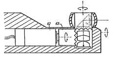
- the operating principles of such a scopeare illustrated schematically in FIG. 1 .
- a variable direction of view endoscopeincludes a shaft 10 having a proximal end 12 .
- Such an endoscopehas a view vector 14 with an attendant view field 16 having at least two degrees of freedom 18 , 20 .
- the first degree of freedom 18permits rotation of the view vector 14 about the longitudinal axis 22 of the shaft 10 , which allows the view vector 14 to scan in a latitudinal direction 24 .
- the second degree of freedom 20permits rotation of the view vector 14 about an axis 26 perpendicular to the longitudinal axis 22 , which allows the view vector 14 to scan in a longitudinal direction 28 .
- a third degree of freedom 30may also be available because it is usually possible to adjust the rotational orientation of the endoscopic image.
- a first prism 32refracts incoming light along a path 34 to a second prism 36 , which delivers the light to an optical relay system 38 housed by a hollow transmission shaft 40 .
- the first prism 32is pivotable about an axis 26 and can be actuated by the transmission shaft 40 through a gear 42 to scan in a plane normal to the page.
- This optical assemblyis covered by a glass dome 43 and supported by a mechanical structure 44 , which forms the distal portion of the endoscope.
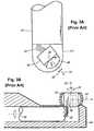
- FIG. 3AA variable direction of view endoscope with a pivotable distal imager is illustrated in FIG. 3A .
- An electronic image sensor 46is located at the tip of the scope shaft 10 and pivots about an axis 26 .
- This arrangementrequires too much room to be able to fit within standard diameters of a significant number of standard endoscopes because the sensor 46 requires integrated objective optics 48 and flexible cabling 50 .
- the solid state imaging devicerequires a set of lenses between the object being viewed and the image plane of the sensor, this assembly must sweep out a large radius when pivoted, which is simply too large for many endoscopic applications. Additionally, the cabling 50 limits the available scan range. Additionally, the mechanisms required to support and actuate such pivotable sensors require some complexity.
- An alternative, similar design, illustrated in FIG. 3Bexperiences these same disadvantages.
- a viewing instrument having a variable direction of viewthat minimizes image degradation.
- a viewing instrument having a variable direction of viewthat can be employed in a small diameter.
- a viewing instrument having a variable direction of viewthat maximizes the scan range of the instrument.
- the inventioncomprises a viewing instrument having a variable direction of view, including a shaft having a distal end and a longitudinal axis, a sensor mounted in the distal end of the shaft, the sensor having an image plane substantially parallel to the longitudinal axis of the shaft, and a reflecting element located at the distal end of the shaft that receives incoming light and redirects the light onto the image plane of the sensor, wherein the element rotates about a rotational axis substantially perpendicular to the longitudinal axis of the shaft.
- the instrumentfurther includes a negative lens located adjacent the reflecting element through which the incoming light is transmitted to the reflecting element, and a convex surface through which the redirected light is transmitted from the reflecting element onto the image plane of the sensor.
- the convex surfaceis a first convex surface
- the instrumentfurther includes a second lens located adjacent the image plane of the sensor, the second lens having a second convex surface through which the light transmitted through the first convex surface is transmitted to the image plane of the sensor.
- the instrumentfurther includes an optical component located between the first convex surface and the second lens, through which the light transmitted through the first convex surface is transmitted to the second lens.
- the inventioncomprises a viewing instrument having a variable direction of view, including a shaft having a distal end and a longitudinal axis, a sensor mounted in the distal end of the shaft, the sensor having an image plane substantially parallel to the longitudinal axis of the shaft, and a reflecting assembly located at the distal end of the shaft that receives incoming light and redirects the light onto the image plane of the sensor, wherein the assembly includes a reflecting element that rotates about a rotational axis substantially perpendicular to the longitudinal axis of the shaft.
- the inventioncomprises a viewing instrument having a variable direction of view, including a shaft having a distal end and a longitudinal axis, a sensor mounted in the distal end of the shaft, the sensor having an image plane substantially parallel to the longitudinal axis of the shaft, and a reflecting assembly located at the distal end of the shaft that receives incoming light and redirects the light onto the image plane of the sensor, wherein the assembly includes a reflecting element that rotates about a rotational axis substantially perpendicular to the longitudinal axis of the shaft.
- the scopehas a distal end, and further includes an optical component located at the distal end of the scope that receives incoming light and redirects the light onto the image plane of the sensor.
- the instrumentfurther includes an optical component that retrofocuses the incoming light.
- an optical component that transmits the redirected light onto the image plane of the sensortelecentrically.
- FIG. 1is a schematic view of the operating principle of an endoscope with a variable direction of view.
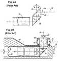
- FIG. 2Ais a schematic view of the optical path of a variable direction of view endoscope employing a relay lens system.
- FIG. 2Bis a side cross-sectional view of a variable direction of view endoscope employing a relay lens system.
- FIG. 3Ais a top plan view of a variable direction of view endoscope employing a pivotable distal imager.
- FIG. 3Bis a side cross-sectional view of a variable direction of view endoscope employing a pivotable distal imager.
- FIG. 4is a side cross-sectional view of a variable direction of view endoscope employing an image sensor in accordance with the invention.
- FIGS. 5A-Hare side views showing additional detail of the image sensor of the endoscope of FIG. 4 .
- FIG. 6is a schematic end view of the inside of the distal end of the endoscope of FIG. 4 .
- FIGS. 7A-Care side cross-sectional views showing additional detail of the actuators for rotating the reflecting element of FIG. 4 .
- FIG. 8is a schematic view of the endoscope of FIG. 4 employing a reflecting assembly for extending the optical path.
- FIG. 4The basic components of one embodiment of a viewing instrument having a variable direction of view in accordance with the invention are illustrated in FIG. 4 .
- the terms “top,” “bottom,” “above,” “below,” “over,” “under,” “above,” “beneath,” “on top,” “underneath,” “up,” “down ,” “upper,” “lower,” “front,” “rear,” “back,” “forward” and “backward”refer to the objects referenced when in the orientation illustrated in the drawings, which orientation is not necessary for achieving the objects of the invention.
- the instrumentincludes a shaft with a distal end 44 and a longitudinal axis 22 , about which the endoscope may be rotated by the user to scan along the first degree of freedom 18 .
- An optical assemblywhich includes a reflecting element 32 for folding the optical path 34 of the assembly, as well as other optical components as further described below, is located at the shaft's distal end 44 .
- the reflecting element 32is rotatable about a rotational axis 26 substantially perpendicular to the longitudinal axis 22 in order to scan along the second degree of freedom 20 .
- the movement of the element 32is powered by an actuator, which may, for example, include a transmission shaft 40 that drives a gear 42 in order to cause the element 32 to rotate and thereby scan in a plane normal to the rotational axis 26 .
- the optical assemblyis covered by a glass dome 43 and is supported by the distal portion 44 of the endoscope shaft 10 .
- An image sensor 46is mounted in the distal portion 44 such that the image plane 45 of the sensor 46 is substantially parallel to the longitudinal axis 22 of the shaft 10 (i.e., side-mounted).
- the reflecting element 32may comprise any component for changing the optical axis of the optical train, further described below, in order to redirect the incoming light onto the image plane 45 of the sensor 46 , such as, for example, a right-angled prism, as is illustrated in FIG. 5A .
- a right-angled prismas is illustrated in FIG. 5A .
- the optical assemblymay include various optical components.
- a negative lens 52such as a plano-concave lens, is mounted adjacent the reflecting element 32 .
- the lens 52has an optical axis substantially perpendicular to the rotational axis of the reflecting element 32 , and receives the incoming light and transmits it to the element 32 , thereby retrofocusing the incoming light.
- the lightis redirected through a convex surface 56 , which may be an integral part of the element 32 or may, for example, be part of a separate plano-convex lens.
- An aperture stop 54 for limiting the diameter of the lightis also provided, which may be placed towards the front or back of the lens train, depending on the types of glass and the particular lens curvatures used.
- a second, positive lens 58is located adjacent the sensor 46 and has an optical axis substantially perpendicular to the optical axis of the negative lens 52 .
- the positive lens 58receives the redirected light from the convex surface of the element 32 and transmits it to the image plane 45 .
- the positive lens 58may comprise, for example, a plano-convex lens, providing a second convex surface through which the light travels prior to reaching the sensor 46 , transmitting the redirected light onto the image plane 45 telecentrically.
- Other positive lensesmay be used, such as, for example, a double-convex lens as illustrated in FIG. 5D .
- the optical assemblyprovides a wide field of view 16 as well as telecentricity of the delimited chief rays 60 at the image plane 45 .
- an additional optical component 61is located between the convex surface 56 and the second lens 58 .
- an achromatic doubletmay be provided for color correction.
- FIG. 5FAnother example of the lens curvatures that may be employed is illustrated in FIG. 5F .
- FIG. 5G-HAnother example of the lens curvatures that may be employed.
- the incident and exiting light conesare more similar than in the optical assemblies described above.
- the chief rays 60are not telecentric when arriving at the sensor plane 46 , which is acceptable for certain types of sensors, and such arrangements may be particularly useful for certain applications because they are very compact.
- FIGS. 7A-Cother actuators for driving the rotation of the reflecting element 32 may also be employed.
- a distal motor 62 with a drive gear 63is implemented.
- a hollow-shaft direct drive motor 64may be provided, which rotates the reflecting element 32 directly.
- a reflecting assemblyis provided that folds the optical path several times.
- a significant challenge for employing distal imagersis the reduced path length.
- the sensor 46must be close to the very tip of the shaft 10 in order to not obstruct the actuator that rotates the element 32 , the light's path from the point of entry into the scope to the sensor 46 is short.
- the angle of incidence onto an image sensorshould be less than 15 degrees.
- the optical pathis extended by providing a reflecting assembly that folds the optical path more than once.
- two additional prisms 66are employed to fold the optical path two additional times, thereby providing approximately 30% more path length while simultaneously keeping these optics and the sensor 46 out of the way of the transmission shaft 40 .
- This type of arrangementallows the chief rays to be bent more gradually over a greater distance.
Landscapes
- Physics & Mathematics (AREA)
- Health & Medical Sciences (AREA)
- Life Sciences & Earth Sciences (AREA)
- Surgery (AREA)
- Optics & Photonics (AREA)
- Engineering & Computer Science (AREA)
- Molecular Biology (AREA)
- Pathology (AREA)
- Radiology & Medical Imaging (AREA)
- Biophysics (AREA)
- General Physics & Mathematics (AREA)
- Biomedical Technology (AREA)
- Heart & Thoracic Surgery (AREA)
- Medical Informatics (AREA)
- Nuclear Medicine, Radiotherapy & Molecular Imaging (AREA)
- Animal Behavior & Ethology (AREA)
- General Health & Medical Sciences (AREA)
- Public Health (AREA)
- Veterinary Medicine (AREA)
- Astronomy & Astrophysics (AREA)
- Instruments For Viewing The Inside Of Hollow Bodies (AREA)
- Endoscopes (AREA)
Abstract
Description
Claims (14)
Priority Applications (3)
| Application Number | Priority Date | Filing Date | Title |
|---|---|---|---|
| CA002533549ACA2533549C (en) | 2005-01-21 | 2006-01-20 | Variable direction of view instrument with distal image sensor |
| US11/336,212US9182577B2 (en) | 2005-01-21 | 2006-01-20 | Variable direction of view instrument with distal image sensor |
| EP06001311.7AEP1683472B2 (en) | 2005-01-21 | 2006-01-23 | Variable direction of view instrument with distal image sensor |
Applications Claiming Priority (2)
| Application Number | Priority Date | Filing Date | Title |
|---|---|---|---|
| US64620305P | 2005-01-21 | 2005-01-21 | |
| US11/336,212US9182577B2 (en) | 2005-01-21 | 2006-01-20 | Variable direction of view instrument with distal image sensor |
Publications (2)
| Publication Number | Publication Date |
|---|---|
| US20060252995A1 US20060252995A1 (en) | 2006-11-09 |
| US9182577B2true US9182577B2 (en) | 2015-11-10 |
Family
ID=36129301
Family Applications (1)
| Application Number | Title | Priority Date | Filing Date |
|---|---|---|---|
| US11/336,212Expired - Fee RelatedUS9182577B2 (en) | 2005-01-21 | 2006-01-20 | Variable direction of view instrument with distal image sensor |
Country Status (3)
| Country | Link |
|---|---|
| US (1) | US9182577B2 (en) |
| EP (1) | EP1683472B2 (en) |
| CA (1) | CA2533549C (en) |
Cited By (5)
| Publication number | Priority date | Publication date | Assignee | Title |
|---|---|---|---|---|
| US20150358519A1 (en)* | 2014-06-06 | 2015-12-10 | Kabushiki Kaisha Toshiba | Camera head, connecting method of camera head and endoscope apparatus |
| US9808144B2 (en) | 2008-07-30 | 2017-11-07 | Acclarent, Inc. | Swing prism endoscope |
| US11032481B2 (en) | 2018-07-06 | 2021-06-08 | Medos International Sarl | Camera scope electronic variable prism |
| US11202014B2 (en) | 2018-07-06 | 2021-12-14 | Medos International Sari | Camera scope electronic variable angle of view |
| US12396621B2 (en) | 2021-12-14 | 2025-08-26 | Karl Storz Imaging, Inc. | Frame processing of imaging scope data for user interface presentation |
Families Citing this family (19)
| Publication number | Priority date | Publication date | Assignee | Title |
|---|---|---|---|---|
| WO2009057085A2 (en)* | 2007-10-30 | 2009-05-07 | Stryker Gi Ltd. | Objective lens for an endoscope of the retrofocus type having an achromat |
| US10092169B2 (en) | 2008-07-08 | 2018-10-09 | Karl Storz Imaging, Inc. | Solid state variable direction of view endoscope |
| US8771177B2 (en) | 2008-07-08 | 2014-07-08 | Karl Storz Imaging, Inc. | Wide angle flexible endoscope |
| US8758234B2 (en) | 2008-07-08 | 2014-06-24 | Karl Storz Imaging, Inc. | Solid state variable direction of view endoscope |
| WO2011013518A1 (en)* | 2009-07-30 | 2011-02-03 | オリンパスメディカルシステムズ株式会社 | Optical system for endoscope, and endoscope |
| WO2011027594A1 (en)* | 2009-09-03 | 2011-03-10 | オリンパスメディカルシステムズ株式会社 | Image pickup unit |
| EP2624039A4 (en) | 2010-12-15 | 2017-07-12 | Olympus Corporation | Endoscope optical system |
| DE102010063230A1 (en)* | 2010-12-16 | 2012-06-21 | Karl Storz Gmbh & Co. Kg | Endoscope with adjustable viewing direction |
| WO2012146664A1 (en)* | 2011-04-26 | 2012-11-01 | Otto-Von-Guericke-Universität Magdeburg Medizinische Fakultät | Endoscope |
| CN103930816A (en) | 2011-11-14 | 2014-07-16 | 皇家飞利浦有限公司 | Light Microscopy Probe for Scanning Microscopy of Associated Objects |
| DE102011089157A1 (en)* | 2011-12-20 | 2013-06-20 | Olympus Winter & Ibe Gmbh | Video endoscope with lateral viewing direction and method for mounting a video endoscope |
| GB201215989D0 (en) | 2012-09-07 | 2012-10-24 | Rolls Royce Plc | A boroscope and a method of processing a component within an assembled apparatus using a boroscope |
| US9408527B2 (en)* | 2012-11-01 | 2016-08-09 | Karl Storz Imaging, Inc. | Solid state variable direction of view endoscope with rotatable wide-angle field for maximal image performance |
| WO2016163447A1 (en) | 2015-04-09 | 2016-10-13 | オリンパス株式会社 | Endoscope objective optical system |
| JP6116780B1 (en) | 2015-07-14 | 2017-04-19 | オリンパス株式会社 | Endoscope |
| JP6886968B2 (en) | 2015-10-09 | 2021-06-16 | コヴィディエン リミテッド パートナーシップ | How to use an angled endoscope to visualize body cavities using a robotic surgical system |
| US20230371789A1 (en)* | 2017-03-09 | 2023-11-23 | Nitesh Ratnakar | Endoscope with self-encased self-illuminating wide-angle panoramic imaging module |
| CN112673295A (en)* | 2018-09-13 | 2021-04-16 | 华为技术有限公司 | Ray path folding structure for imaging system and electronic device including the same |
| GB2591321B (en)* | 2020-10-15 | 2022-06-22 | James Ian Hamilton Nicholas | Throat examination apparatus |
Citations (22)
| Publication number | Priority date | Publication date | Assignee | Title |
|---|---|---|---|---|
| US2764149A (en) | 1951-05-23 | 1956-09-25 | Sheldon Edward Emanuel | Electrical device for the examination of the interior of the human body |
| US3856000A (en) | 1972-06-19 | 1974-12-24 | Machido Seisakusho Kk | Endoscope |
| US4074306A (en) | 1975-07-28 | 1978-02-14 | Olympus Optical Co., Ltd. | Endoscope utilizing color television and fiber optics techniques |
| US4253447A (en) | 1978-10-16 | 1981-03-03 | Welch Allyn, Inc. | Color endoscope with charge coupled device and television viewing |
| US4598980A (en)* | 1983-07-23 | 1986-07-08 | Fuji Photo Optical Co., Ltd. | Objective optical system for endoscope |
| US4697577A (en) | 1986-05-22 | 1987-10-06 | Baxter Travenol Laboratories, Inc. | Scanning microtelescope for surgical applications |
| US4720178A (en)* | 1984-08-15 | 1988-01-19 | Olympus Optical Co., Ltd. | Optical system for endoscope |
| US4868644A (en)* | 1987-04-01 | 1989-09-19 | Olympus Optical Co. | Electronic endoscope with solid state imaging device |
| US4890159A (en) | 1988-02-04 | 1989-12-26 | Olympus Optical Co., Ltd. | Endoscope system and method of unifying picture images in an endoscope system |
| US4916534A (en)* | 1987-04-28 | 1990-04-10 | Olympus Optical Co., Ltd. | Endoscope |
| US4988172A (en)* | 1988-01-30 | 1991-01-29 | Olympus Optical Co., Ltd. | Optical system for endoscopes |
| US5166787A (en) | 1989-06-28 | 1992-11-24 | Karl Storz Gmbh & Co. | Endoscope having provision for repositioning a video sensor to a location which does not provide the same cross-sectionally viewed relationship with the distal end |
| US5762603A (en) | 1995-09-15 | 1998-06-09 | Pinotage, Llc | Endoscope having elevation and azimuth control of camera assembly |
| US6256155B1 (en)* | 1998-09-11 | 2001-07-03 | Olympus Optical Co., Ltd. | Objective optical system |
| US20010031912A1 (en) | 2000-04-10 | 2001-10-18 | Cbeyond Inc. | Image sensor and an endoscope using the same |
| US6371909B1 (en) | 1998-02-19 | 2002-04-16 | California Institute Of Technology | Apparatus and method for providing spherical viewing during endoscopic procedures |
| US20020068853A1 (en)* | 2000-04-10 | 2002-06-06 | Doron Adler | Intra vascular imaging method and apparatus |
| US6500115B2 (en) | 1998-08-28 | 2002-12-31 | Storz Endoskop Gmbh | Endoscope |
| US6560013B1 (en) | 1999-09-28 | 2003-05-06 | Keymed (Medical & Industrial Equipment) Ltd. | Endoscope with variable direction of view |
| US6648817B2 (en)* | 2001-11-15 | 2003-11-18 | Endactive, Inc. | Apparatus and method for stereo viewing in variable direction-of-view endoscopy |
| US6731845B1 (en) | 1990-06-19 | 2004-05-04 | Sperry Marine Inc. | Panoramic visual system for non-rotating structures |
| US6788861B1 (en)* | 1999-08-10 | 2004-09-07 | Pentax Corporation | Endoscope system, scanning optical system and polygon mirror |
Family Cites Families (4)
| Publication number | Priority date | Publication date | Assignee | Title |
|---|---|---|---|---|
| US4759347A (en)* | 1981-09-12 | 1988-07-26 | Fuji Photo Optical Company, Ltd. | Endoscope apparatus using solid state image pickup device |
| JPS60104915A (en)† | 1983-11-11 | 1985-06-10 | Fuji Photo Optical Co Ltd | Endoscope |
| DE4241938B4 (en)* | 1992-12-11 | 2004-11-04 | Karl Storz Gmbh & Co. Kg | Endoscope especially with stereo side-view optics |
| DE10327747A1 (en)* | 2003-06-18 | 2005-01-13 | Viktor Josef Wimmer | Optic unit for sidelight duodenoscopes |
- 2006
- 2006-01-20CACA002533549Apatent/CA2533549C/ennot_activeExpired - Fee Related
- 2006-01-20USUS11/336,212patent/US9182577B2/ennot_activeExpired - Fee Related
- 2006-01-23EPEP06001311.7Apatent/EP1683472B2/ennot_activeNot-in-force
Patent Citations (22)
| Publication number | Priority date | Publication date | Assignee | Title |
|---|---|---|---|---|
| US2764149A (en) | 1951-05-23 | 1956-09-25 | Sheldon Edward Emanuel | Electrical device for the examination of the interior of the human body |
| US3856000A (en) | 1972-06-19 | 1974-12-24 | Machido Seisakusho Kk | Endoscope |
| US4074306A (en) | 1975-07-28 | 1978-02-14 | Olympus Optical Co., Ltd. | Endoscope utilizing color television and fiber optics techniques |
| US4253447A (en) | 1978-10-16 | 1981-03-03 | Welch Allyn, Inc. | Color endoscope with charge coupled device and television viewing |
| US4598980A (en)* | 1983-07-23 | 1986-07-08 | Fuji Photo Optical Co., Ltd. | Objective optical system for endoscope |
| US4720178A (en)* | 1984-08-15 | 1988-01-19 | Olympus Optical Co., Ltd. | Optical system for endoscope |
| US4697577A (en) | 1986-05-22 | 1987-10-06 | Baxter Travenol Laboratories, Inc. | Scanning microtelescope for surgical applications |
| US4868644A (en)* | 1987-04-01 | 1989-09-19 | Olympus Optical Co. | Electronic endoscope with solid state imaging device |
| US4916534A (en)* | 1987-04-28 | 1990-04-10 | Olympus Optical Co., Ltd. | Endoscope |
| US4988172A (en)* | 1988-01-30 | 1991-01-29 | Olympus Optical Co., Ltd. | Optical system for endoscopes |
| US4890159A (en) | 1988-02-04 | 1989-12-26 | Olympus Optical Co., Ltd. | Endoscope system and method of unifying picture images in an endoscope system |
| US5166787A (en) | 1989-06-28 | 1992-11-24 | Karl Storz Gmbh & Co. | Endoscope having provision for repositioning a video sensor to a location which does not provide the same cross-sectionally viewed relationship with the distal end |
| US6731845B1 (en) | 1990-06-19 | 2004-05-04 | Sperry Marine Inc. | Panoramic visual system for non-rotating structures |
| US5762603A (en) | 1995-09-15 | 1998-06-09 | Pinotage, Llc | Endoscope having elevation and azimuth control of camera assembly |
| US6371909B1 (en) | 1998-02-19 | 2002-04-16 | California Institute Of Technology | Apparatus and method for providing spherical viewing during endoscopic procedures |
| US6500115B2 (en) | 1998-08-28 | 2002-12-31 | Storz Endoskop Gmbh | Endoscope |
| US6256155B1 (en)* | 1998-09-11 | 2001-07-03 | Olympus Optical Co., Ltd. | Objective optical system |
| US6788861B1 (en)* | 1999-08-10 | 2004-09-07 | Pentax Corporation | Endoscope system, scanning optical system and polygon mirror |
| US6560013B1 (en) | 1999-09-28 | 2003-05-06 | Keymed (Medical & Industrial Equipment) Ltd. | Endoscope with variable direction of view |
| US20010031912A1 (en) | 2000-04-10 | 2001-10-18 | Cbeyond Inc. | Image sensor and an endoscope using the same |
| US20020068853A1 (en)* | 2000-04-10 | 2002-06-06 | Doron Adler | Intra vascular imaging method and apparatus |
| US6648817B2 (en)* | 2001-11-15 | 2003-11-18 | Endactive, Inc. | Apparatus and method for stereo viewing in variable direction-of-view endoscopy |
Cited By (8)
| Publication number | Priority date | Publication date | Assignee | Title |
|---|---|---|---|---|
| US9808144B2 (en) | 2008-07-30 | 2017-11-07 | Acclarent, Inc. | Swing prism endoscope |
| US20150358519A1 (en)* | 2014-06-06 | 2015-12-10 | Kabushiki Kaisha Toshiba | Camera head, connecting method of camera head and endoscope apparatus |
| US11032481B2 (en) | 2018-07-06 | 2021-06-08 | Medos International Sarl | Camera scope electronic variable prism |
| US11202014B2 (en) | 2018-07-06 | 2021-12-14 | Medos International Sari | Camera scope electronic variable angle of view |
| US11317029B2 (en) | 2018-07-06 | 2022-04-26 | Medos International Sarl | Camera scope electronic variable prism |
| US12082772B2 (en) | 2018-07-06 | 2024-09-10 | Medos International Sarl | Camera scope electronic variable prism |
| US12200364B2 (en) | 2018-07-06 | 2025-01-14 | Medos International Sarl | Camera scope electronic variable prism |
| US12396621B2 (en) | 2021-12-14 | 2025-08-26 | Karl Storz Imaging, Inc. | Frame processing of imaging scope data for user interface presentation |
Also Published As
| Publication number | Publication date |
|---|---|
| CA2533549A1 (en) | 2006-07-21 |
| EP1683472A1 (en) | 2006-07-26 |
| EP1683472B1 (en) | 2011-08-17 |
| EP1683472B2 (en) | 2019-09-25 |
| CA2533549C (en) | 2009-12-15 |
| US20060252995A1 (en) | 2006-11-09 |
Similar Documents
| Publication | Publication Date | Title |
|---|---|---|
| US9182577B2 (en) | Variable direction of view instrument with distal image sensor | |
| US7221522B2 (en) | Optical system for variable direction of view instrument | |
| JP4458221B2 (en) | Endoscope with variable viewing direction | |
| US7896803B2 (en) | Variable direction of view instrument with on-board actuators | |
| US6638216B1 (en) | Variable view arthroscope | |
| US2987960A (en) | Optical system for endoscopes and the like | |
| US8031416B2 (en) | Endoscope | |
| EP1019756B1 (en) | Sapphire objective system | |
| JP2007509710A (en) | Variable-field arthroscope using CCD | |
| JP2007075604A (en) | Visual direction adjustable type endoscope | |
| US20220187588A1 (en) | Observation Instrument and Video Imager Arrangement Therefor | |
| ES2604138T3 (en) | A scanner for an endoscope | |
| JP2006201796A (en) | Variable directivity of viewing apparatus equipped with image sensor at tip | |
| US9405114B2 (en) | Camera module for endoscope | |
| Babayan et al. | Optics of Flexible and Rigid Endoscopes: Physical Principals... I | |
| JP2001208951A (en) | Endoscope with objective lens moving mechanism | |
| HK1057982B (en) | Variable view arthroscope |
Legal Events
| Date | Code | Title | Description |
|---|---|---|---|
| AS | Assignment | Owner name:KARL STORZ DEVELOPMENT CORP., CALIFORNIA Free format text:ASSIGNMENT OF ASSIGNORS INTEREST;ASSIGNORS:HOEG, HANS DAVID;SCHARA, NATHAN JON;HALE, ERIC L.;AND OTHERS;REEL/FRAME:017918/0446;SIGNING DATES FROM 20060406 TO 20060630 Owner name:KARL STORZ DEVELOPMENT CORP., CALIFORNIA Free format text:ASSIGNMENT OF ASSIGNORS INTEREST;ASSIGNORS:HOEG, HANS DAVID;SCHARA, NATHAN JON;HALE, ERIC L.;AND OTHERS;SIGNING DATES FROM 20060406 TO 20060630;REEL/FRAME:017918/0446 | |
| AS | Assignment | Owner name:KARL STORZ IMAGING, INC., CALIFORNIA Free format text:NUNC PRO TUNC ASSIGNMENT;ASSIGNOR:KARL STORZ DEVELOPMENT CORP.;REEL/FRAME:025114/0991 Effective date:20101004 | |
| ZAAA | Notice of allowance and fees due | Free format text:ORIGINAL CODE: NOA | |
| ZAAB | Notice of allowance mailed | Free format text:ORIGINAL CODE: MN/=. | |
| STCF | Information on status: patent grant | Free format text:PATENTED CASE | |
| MAFP | Maintenance fee payment | Free format text:PAYMENT OF MAINTENANCE FEE, 4TH YEAR, LARGE ENTITY (ORIGINAL EVENT CODE: M1551); ENTITY STATUS OF PATENT OWNER: LARGE ENTITY Year of fee payment:4 | |
| FEPP | Fee payment procedure | Free format text:MAINTENANCE FEE REMINDER MAILED (ORIGINAL EVENT CODE: REM.); ENTITY STATUS OF PATENT OWNER: LARGE ENTITY | |
| LAPS | Lapse for failure to pay maintenance fees | Free format text:PATENT EXPIRED FOR FAILURE TO PAY MAINTENANCE FEES (ORIGINAL EVENT CODE: EXP.); ENTITY STATUS OF PATENT OWNER: LARGE ENTITY | |
| STCH | Information on status: patent discontinuation | Free format text:PATENT EXPIRED DUE TO NONPAYMENT OF MAINTENANCE FEES UNDER 37 CFR 1.362 | |
| FP | Lapsed due to failure to pay maintenance fee | Effective date:20231110 |