US9182563B2 - Adapter plate for fiber optic module - Google Patents
Adapter plate for fiber optic moduleDownload PDFInfo
- Publication number
- US9182563B2 US9182563B2US13/432,762US201213432762AUS9182563B2US 9182563 B2US9182563 B2US 9182563B2US 201213432762 AUS201213432762 AUS 201213432762AUS 9182563 B2US9182563 B2US 9182563B2
- Authority
- US
- United States
- Prior art keywords
- adapter plate
- module
- telecommunications
- chassis
- telecommunications module
- Prior art date
- Legal status (The legal status is an assumption and is not a legal conclusion. Google has not performed a legal analysis and makes no representation as to the accuracy of the status listed.)
- Expired - Fee Related, expires
Links
Images


Classifications
- G—PHYSICS
- G02—OPTICS
- G02B—OPTICAL ELEMENTS, SYSTEMS OR APPARATUS
- G02B6/00—Light guides; Structural details of arrangements comprising light guides and other optical elements, e.g. couplings
- G02B6/44—Mechanical structures for providing tensile strength and external protection for fibres, e.g. optical transmission cables
- G02B6/4439—Auxiliary devices
- G02B6/444—Systems or boxes with surplus lengths
- G02B6/4452—Distribution frames
- G02B6/44526—Panels or rackmounts covering a whole width of the frame or rack
- G—PHYSICS
- G02—OPTICS
- G02B—OPTICAL ELEMENTS, SYSTEMS OR APPARATUS
- G02B6/00—Light guides; Structural details of arrangements comprising light guides and other optical elements, e.g. couplings
- G02B6/44—Mechanical structures for providing tensile strength and external protection for fibres, e.g. optical transmission cables
- G02B6/4439—Auxiliary devices
- G02B6/444—Systems or boxes with surplus lengths
- G02B6/4452—Distribution frames
- G—PHYSICS
- G02—OPTICS
- G02B—OPTICAL ELEMENTS, SYSTEMS OR APPARATUS
- G02B6/00—Light guides; Structural details of arrangements comprising light guides and other optical elements, e.g. couplings
- G02B6/44—Mechanical structures for providing tensile strength and external protection for fibres, e.g. optical transmission cables
- G02B6/4439—Auxiliary devices
- G02B6/444—Systems or boxes with surplus lengths
- G02B6/44528—Patch-cords; Connector arrangements in the system or in the box
- G—PHYSICS
- G02—OPTICS
- G02B—OPTICAL ELEMENTS, SYSTEMS OR APPARATUS
- G02B6/00—Light guides; Structural details of arrangements comprising light guides and other optical elements, e.g. couplings
- G02B6/44—Mechanical structures for providing tensile strength and external protection for fibres, e.g. optical transmission cables
- G02B6/4439—Auxiliary devices
- G02B6/444—Systems or boxes with surplus lengths
- G02B6/4453—Cassettes
- G02B6/4455—Cassettes characterised by the way of extraction or insertion of the cassette in the distribution frame, e.g. pivoting, sliding, rotating or gliding
- G—PHYSICS
- G02—OPTICS
- G02B—OPTICAL ELEMENTS, SYSTEMS OR APPARATUS
- G02B6/00—Light guides; Structural details of arrangements comprising light guides and other optical elements, e.g. couplings
- G02B6/44—Mechanical structures for providing tensile strength and external protection for fibres, e.g. optical transmission cables
- G02B6/4439—Auxiliary devices
- G02B6/4471—Terminating devices ; Cable clamps
- G02B6/44785—Cable clamps
- Y—GENERAL TAGGING OF NEW TECHNOLOGICAL DEVELOPMENTS; GENERAL TAGGING OF CROSS-SECTIONAL TECHNOLOGIES SPANNING OVER SEVERAL SECTIONS OF THE IPC; TECHNICAL SUBJECTS COVERED BY FORMER USPC CROSS-REFERENCE ART COLLECTIONS [XRACs] AND DIGESTS
- Y10—TECHNICAL SUBJECTS COVERED BY FORMER USPC
- Y10T—TECHNICAL SUBJECTS COVERED BY FORMER US CLASSIFICATION
- Y10T29/00—Metal working
- Y10T29/49—Method of mechanical manufacture
- Y10T29/49826—Assembling or joining
- Y10T29/49863—Assembling or joining with prestressing of part
- Y10T29/4987—Elastic joining of parts
Definitions
- the present disclosuregenerally relates to fiber optic telecommunications equipment. More specifically, the present disclosure relates to an adapter plate for use with a fiber optic module, wherein the fiber optic module is normally configured to be mounted to a first piece of telecommunications equipment without the adapter plate and wherein the adapter plate allows the fiber optic module to be mounted to a different second piece of telecommunications equipment.
- modules including splitters or fanoutsare used to provide the connection between transmission fibers and customer fibers.
- a module mounting chassiscapable of mounting multiple modules may be used in such an installation.
- chassis for mounting modulesmay vary depending upon the application, the capacity, and the location thereof.
- the modules that include the fiber optic equipmentare normally specifically designed for a given chassis. What is needed is a system that allows a module that is configured for a first type of chassis to be able to be installed in a second type of chassis without having to modify the external and internal features of the module.
- the present inventionrelates to an adapter plate for use with a fiber optic module, wherein the fiber optic module is normally configured to be mounted to a first piece of telecommunications equipment without the adapter plate and wherein the adapter plate allows the fiber optic module to be mounted to a second piece of telecommunications equipment having a different configuration than the first piece of telecommunications equipment.
- the adapter plateslidably and removably mounts on the exterior of the fiber optic module for converting the configuration of the module for installation in a type of telecommunications equipment that is different than the type of telecommunications equipment that the module was configured for without the adapter plate.
- an adapter plate for use with a telecommunications module that is configured to be slidably inserted into a first type of telecommunications chassiscomprises a body configured to be mounted to the telecommunications module.
- the body of the adapter plateincludes structure for mounting the telecommunications module to a second type of telecommunications chassis that is different than the first type of telecommunications chassis, wherein the telecommunications module is not configured to be mounted to the second type of telecommunications chassis without the adapter plate.
- the adapter plateis for use with a telecommunications module that includes a flexible latch for interlocking with a first type of telecommunications chassis.
- the adapter platecomprises a body configured to be mounted to the telecommunications module and interlocked with the telecommunications module using the flexible latch of the telecommunications module, wherein the body of the adapter plate includes a second latch for interlocking with a second type of telecommunications chassis that is different than the first type of telecommunications chassis, wherein the flexible latch of the telecommunications module is not configured for interlocking with the second type of telecommunications chassis.
- a method of mounting a telecommunications module to a second type of telecommunications chassiswherein the telecommunications module is normally configured for mounting to a first telecommunications chassis with a flexible latch and the second telecommunications chassis is different than the first telecommunications chassis such that the flexible latch is not configured for mounting to the second telecommunications chassis.
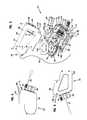
- FIG. 1is a front perspective view of a prior art fiber termination block that is configured to be mounted in a high-density fiber distribution frame, shown with a fiber optic module exploded off a module chassis of the fiber termination block;
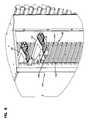
- FIG. 2illustrates a closer view of the module chassis of the fiber termination block of FIG. 1 , the module chassis shown with one fiber optic module mounted therein;
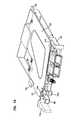
- FIG. 3illustrates an exploded view of one of the prior art fiber optic modules shown installed in the fiber termination block of FIG. 1 ;
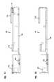
- FIG. 4is left side view of the fiber optic module of FIG. 3 ;
- FIG. 5is a right side view of the fiber optic module of FIG. 3 ;
- FIG. 6is right side view of the fiber optic module of FIG. 3 , shown without the cover thereof exposing the interior features of the fiber optic module;
- FIG. 7illustrates the fiber optic module of FIG. 3 in combination with a prior art fiber optic adapter module configured to hold a plurality of fiber optic adapters, the fiber optic adapter module also configured for installation in a piece of telecommunications equipment such as the fiber termination block as shown in FIG. 1 ;
- FIG. 8illustrates the fiber optic module of FIGS. 1-7 installed in a second type of a module chassis with the use of an adapter plate having features that are examples of inventive aspects in accordance with the present disclosure
- FIG. 9illustrates the fiber optic module of FIGS. 1-7 partially installed in the adapter plate shown in FIG. 8 ;
- FIG. 10illustrates the fiber optic module of FIG. 9 fully installed in the adapter plate of FIG. 9 ;
- FIG. 11is a right side view of the fiber optic module fully installed in the adapter plate of FIG. 10 ;
- FIG. 12is front view of the fiber optic module fully installed in the adapter plate of FIG. 10 ;
- FIG. 13is a front perspective view of the adapter plate of FIG. 10 shown in isolation, the adapter plate having features that are examples of inventive aspects in accordance with the present disclosure;
- FIG. 14is a right side view of the adapter plate of FIG. 13 ;
- FIG. 15is a front view of the adapter plate of FIG. 13 ;
- FIG. 16is a top view of the adapter plate of FIG. 13 ;
- FIG. 17is a bottom view of the adapter plate of FIG. 13 ;
- FIG. 18illustrates a cross-section taken along line 18 - 18 of FIG. 14 .
- FIG. 1illustrates a prior art fiber termination block 10 that is configured to be mounted in a high-density fiber distribution frame.
- the fiber termination block 10includes a front area 12 which defines a plurality of fiber optic terminations, such as adapters 14 which connect axially aligned fiber optic connectors.
- a rear area 16 of block 10defines a fiber optic module chassis area 18 and a slack storage area 20 .
- the fiber optic modules 22 to be used in the block 10can include various types of fiber optic equipment, such as for increasing capacity.
- the example embodiments of the fiber optic modules that will be described in the present applicationare splitter modules 22 that are configured to split an input signal into a plurality of the same output signals.
- the fiber termination block 10includes a plurality of covers to selectively protect internal components. Termination access panels 24 protect front area and the fiber optic terminations contained therein. A rear access cover (not shown) protects module chassis 18 and slack storage areas 20 . Latches 26 allow for selective pivoting of panels 24 or removal of cover.
- the fiber termination block 10 and the features thereofare described in further detail in U.S. Pat. No. 7,590,328, the entire disclosure of which is herein incorporated by reference.
- the fiber termination block 10is shown as including front radius limiters 28 and divider walls 30 .
- Divider walls 30receive slidable adapter modules 32 .
- Divider walls 30 and adapter modules 32are preferably constructed as described in U.S. Pat. No. 6,591,051, the entire disclosure of which is herein incorporated by reference. Additional sliding adapter arrangements are described in U.S. Pat. Nos. 5,497,444, 5,717,810, and 7,416,349, the entire disclosures of which are herein incorporated by reference.
- Divider walls 30define longitudinal guides 34 for receiving longitudinal guides 36 of the sliding adapter modules 32 . Guides 34 are shown in the form of channels 38 and guides 36 are shown in the form of rails 40 .
- Each adapter module 32includes a plurality of adapters 14 for receiving and connecting two fiber optic connectors. SC type connectors and mating adapters are shown.
- Divider walls 30define a left side and right side for left and right adapter modules 32 to slide in opposite directions. Spaces or slots 42 between divider walls 30 each receive one of the adapter modules 32 during use.
- the chassis 18 positioned in the rear area 16 of the fiber termination block 10is configured for holding one or more fiber optic modules 22 . Signals output from the modules 22 are directed to the adapter modules 32 positioned on the front area 12 of the fiber termination block 10 .
- the fiber optic modules 22 housed in the chassis 18may be configured to include different types of fiber optic equipment such as splitters, fan-outs, multiplexers/demultiplexers, combiners, filters, etc.
- the example shown and described in the present application and that is configured for the high-density fiber termination block 10 shown in FIG. 1is a fiber optic splitter module 22 .
- Each fiber optic splitter module 22includes at least one input 44 and a plurality of outputs 46 . The inputs 44 and the outputs 46 are provided by connectorized cables 45 , 51 , respectively as seen in FIGS. 3 , 6 , and 7 .
- FIGS. 3-7one of the modules 22 mounted within the chassis 18 of the fiber termination block 10 is shown in closer detail.
- the module 22 shown in the Figures of the present applicationcan be configured to have a front input location or a rear input location.
- the front input locationmay include one or more inputs 44 provided by one or more cables.
- the module 22is shown as a single input module in FIGS. 2 and 7 and is shown as a dual-input module in FIGS. 1 and 3 - 6 .
- the cover 48 of the module 22allows the module 22 to be converted between a single or a dual input module.
- the splitters 50 provided in the modules 22can be any configuration desired by the customer, including for example 1 ⁇ 32, 1 ⁇ 16, or dual 1 ⁇ 16 splitters. If splitter module 22 only has one input 44 , then only one input cable is provided. If dual inputs 44 are desired, then two input cables are used as shown in FIGS. 1 and 3 - 6 .
- splitter module 22 shown and described hereinis simply one example of a fiber optic module that is used to describe the inventive principles of the present disclosure and that the inventive aspects may be applicable to other types of modules.
- U.S. Pat. No. 7,885,505the entire disclosure of which is herein incorporated by reference, describes different versions of the module shown in the present application, some having front inputs, some having rear inputs, some including different fiber optic equipment therein such as an optical wavelength division multiplexer/demultiplexer.
- each splitter module 22includes flanges 52 , 54 formed by the cover 48 of the module which are received in mounting channels/slots 56 defined by mounting locations 15 in chassis 18 .
- the module chassis 18defines four mounting channels/slots 56 for receiving four splitter modules 22 from an open front end 13 .
- each splitter module 22is received within one of the mounting slots 56 within splitter module chassis 18 .
- the module chassis 18may be mounted at a slight angle relative to a rear area 16 of the block 10 , and a slight angle relative to a side 11 of the block 10 .
- the open end 13may be both tipped to the open side 11 and tipped down. Such a positioning may improve cable management by not excessively bending the cables to and from each splitter module 22 .
- the splitter modules 22include a latch 58 for selective latching to module chassis 18 . Details of how the module 22 latches to a mounting location 15 within the chassis 18 are described in further detail in U.S. Pat. No. 7,885,505, the entire disclosure of which has been incorporated herein by reference.
- the fiber optic splitter module 22includes a splitter module housing 60 .
- Splitter module housing 60includes a main housing portion 62 and the removable cover 48 .
- Main housing portion 62includes a first transverse sidewall 64 extending between a top wall 66 , a bottom wall 68 , a rear wall 70 , and a front wall 72 .
- Removable cover 48defines a second transverse wall 74 of splitter module housing 60 and closes off an open side 76 of module main housing 62 .
- Cover 48is mounted to main housing portion 62 by fasteners 78 through fastener mounts 80 defined on main housing portion 62 . As noted above, the cover 48 extends beyond first transverse sidewall 64 to form a top mounting flange 52 and a bottom mounting flange 54 of splitter module 22 .
- the bottom flange 54 of splitter module housing 60 and the corresponding mounting slot 56 on chassis 18may be smaller in size than top flange 52 and the corresponding top slot 56 on chassis 18 .
- Bottom slot 56may be sized so that, while bottom flange 54 may be received within slot 56 , the larger top flange 52 will not fit. This ensures that modules 22 are positioned within the chassis 18 in a particular desired orientation.
- the rear wall 70 of main housing portion 62includes a curved portion 82 configured to provide bend radius protection to cables within interior.
- Rear wall 70 of main housing 62also includes an inset portion 84 .
- a pair of fiber optic connectors 86may be positioned at inset portion 84 and protrude rearwardly from rear wall 70 for mating with fiber optic adapters for an input signal.
- the rear input locations 44are plugged with inserts 88 and only the front input locations 44 are used.
- the rear wall 70 of the module 22is shown populated with fiber optic connectors 86 even though the module 22 is being used as a front input module.
- each module 22includes two cable exits/outputs 46 extending from front wall 72 of module main housing 62 .
- the cable exits 46are slidably mounted to main housing 62 of module 22 and captured by cover 48 of module 22 when cover 48 is mounted to main housing 62 .
- Cable exits 46define a protruding rear lip 92 that is slidably inserted into slots 94 defined around front apertures 96 for accommodating cable exits 46 .
- Cover 48also includes slits 98 that receive rear lips 92 of the cable exits 46 to capture cable exits 46 .
- Cable exits 46permit telecommunications cables within module 22 to be directed outside of module 22 .
- Cable exits 46are normally sized thin enough to fit within the profile of the fiber optic splitter module 22 to preserve the density of the telecommunications assembly.
- the cables exiting the modules 22 that carry the split signalsmay include connectorized ends that are directed to adapter modules 32 , such as shown in FIG. 7 and such as shown in the termination block 10 of FIG. 1 .
- the terminated output endscan be lead to parking structures for storage for future connectivity, as described in further detail in U.S. Pat. No. 7,218,827, incorporated herein by reference in its entirety.
- the main housing 62includes an integrally formed flexible latch 58 (i.e., cantilever arm) that is adapted to engage a portion of chassis 18 to hold module 22 within front opening 13 of chassis 18 .
- Flexible latch 58also deflects to permit withdrawal of module 22 from chassis 18 .
- the latch 58 of module 22includes a finger grip tab 100 , a front latching tab 102 and a rear latching tab 104 .
- Front latching tab 102 and rear latching tab 104define a recess 106 thereinbetween.
- Rear latching tab 104includes a ramped face 108 that causes latch 58 to elastically deflect down when module 22 is being inserted into chassis 18 .
- Rear latching tab 104also includes a square face 110 that opposes a square face 112 of front latching tab 102 .
- a front lip 114 defined by the mounting location 15 of chassis 18is captured in recess 106 between the two latching tabs 102 , 104 to hold module 22 in place within chassis 18 .
- latch 58flexes back upwardly.
- Module 22includes a fixed grip tab 116 opposing and adjacent to flexible latch 58 to aid removal of module 22 from chassis 18 .
- Fixed grip tab 116is formed as a part of front wall 72 of module 22 .
- Fixed grip tab 116is positioned on module 22 opposite latch 58 so that a user may apply opposing force on latch 58 and fixed grip tab 116 to securely grasp module 22 and remove it from chassis 18 .
- Fixed grip tab 116is positioned on module 22 close enough to latch 58 so that a user may be able to apply the force with two adjacent fingers of the hand.
- FIG. 3shows an exploded view of fiber optic splitter module 22 illustrating the internal components of module 22 .
- the front wall 72 of the module housing 60defines two recesses 118 that are sized to accommodate the terminated cables 45 .
- the cover 48includes two tabs 120 that are normally used to cover the recesses 118 located on the front wall 72 of the module housing 60 .
- the tabs 120are cut to appropriate length to accommodate the cables 45 and capture the terminations within the recesses 118 .
- the front input cables 45are arranged in a side by side configuration along a direction extending from the top wall 66 of the module 22 toward the bottom wall 68 of the module 22 .
- modules 22may include front input locations 44 that are configured to receive input cables 45 in a stacked arrangement along a direction extending from the first sidewall 64 of the module toward the second sidewall 74 defined by the cover 48 of the module 22 , examples of which are shown in U.S. Pat. No. 7,885,505, the entire disclosure of which has been incorporated herein by reference.
- the optical component 50(e.g., the splitter) is held against the interior of bottom wall 68 by a clamp 122 (i.e., bracket).
- Clamp 122is mounted to a clamp mount defined on splitter module main housing 62 with fasteners (not shown).
- the clamp mountincludes two pairs of mounting holes 124 . Either the upper set of holes 124 a or the lower set of holes 124 b are utilized depending upon the size of the clamp 122 that will be used to hold optical component 50 against bottom wall 68 .
- different optical components 50may have different thicknesses and may require the use of different sized clamps 122 for holding the optical components 50 in place.
- two optical components 50 that are stacked on top of anothermay be used, in which case, a smaller clamp 122 would be used to hold the two optical components 50 in place.
- the splitter module main housing 62also includes integrally formed crimp holders 126 (e.g., slots) adjacent front wall 72 of housing 60 underneath radius limiter 128 .
- Crimp elements 130crimped to the ends of cables 47 that are split by splitter 50 are slidably received into crimp holders 126 as shown in FIG. 3 .
- Crimp elements 130define square flanges 132 between which is defined a recessed portion 134 .
- the crimp holders 126include complementary structure to the crimp elements 130 such that once the crimp elements 130 are slidably inserted into the crimp holders 126 , the crimp elements 130 are prevented from moving in a longitudinal direction due to the flanges 132 .
- crimp elements 130are held in place by cover 48 that is mounted to splitter module main housing 62 .
- Other complementary shapes between the crimp elements 130 and the crimp holding slots 126are also possible to provide a slidable fit and to prevent axial movement of the crimp elements 130 once inserted therein the crimp holders 126 .
- a first input cable 45extends from the front input location 44 around a radius limiter 128 toward the rear wall 70 of the module 22 .
- the first cable 45is looped around a radius limiter in the form of a spool 138 . From the spool 138 , the first cable 45 extends toward the front wall 72 of the module 22 and around the radius limiter 128 downwardly toward the optical component 50 , mounted within module housing 60 .
- Optical component 50 within the modulemay be a splitter or another type of optical component.
- optical component 50is a fiber optic splitter that splits the signal of a single strand 45 to a plurality of secondary signals 47 .
- First input cable 45is received into the optical component 50 and the signal is split into a plurality of signals carried by a plurality of cables 47 that are bundled into a second cable 49 .
- Second cable 49extends from optical component 50 toward the rear wall 70 of the module 22 and is looped again all the way around spool 138 before heading toward crimp holders 126 .
- a fiber retainer 140may be used, as shown in FIG. 3 , to keep the fiber optic cable 49 around the spool 138 .
- the bundled second cable 49is separated into individual cables 47 as it leaves the spool 138 .
- the individual cables 47are crimped to output cables 51 at the crimp holders 126 and the output cables 51 exit the module 22 through module exits 46 .
- routing of the fiber optic cables within module 22 as shown in FIGS. 3 and 6is only one example and other ways of routing the cables within the module 22 are possible.
- FIGS. 8-18illustrate an adapter plate 90 that is configured to allow the fiber optic module 22 to be mounted to a chassis 142 that is different than the chassis 18 shown in FIG. 1 .
- the adapter plate 90is configured to be slidably and removably mounted on the exterior of the fiber optic module 22 .
- the adapter plate 90converts the configuration of the module 22 for installation in a type of telecommunications equipment that is different than the type of telecommunications equipment that the module 22 was initially designed for without the adapter plate 90 (e.g., the chassis 18 of the fiber termination block 10 shown in FIG. 1 that includes opposing slots 56 at the mounting locations 15 and a front lip 114 configured to engage the latch 58 of the module 22 ).
- the second chassis 142 that includes opposing mounting slots 144is shown populated with a number of the splitter modules 22 discussed above.
- the chassis 142unlike the chassis 18 of the termination block 10 of FIGS. 1-2 , does not include front lips 114 that are configured to interlock with the integral latches 58 of the fiber optic modules 22 and the spacing between the mounting slots 144 is different than that of the type of chassis 18 shown in FIGS. 1-2 .
- the spacing between the opposing slots 144 of a given mounting location 145are different and the spacing between adjacent slots 144 of adjacent mounting locations 145 are different.
- each mounting location 145 of the chassisdefines an opening 146 that is configured to accept a swell-latch type of an interlock structure.
- the modules 22which are not normally designed for the type of chassis 142 shown in FIG. 8 , can nevertheless be mounted within the chassis 142 shown in FIG. 8 .
- a chassis similar to the second chassis 142is shown and described in greater detail (see FIG. 66 ) in U.S. Pat. No. 6,760,531, the entire disclosure of which is incorporated herein by reference.
- the second chassis 142might be used in a fiber telecommunications frame that is shown and described in U.S. Pat. No. 6,760,531 that might be configured for splicing, terminating, and managing/storing fiber optic cables within the frame.
- the adapter plate 90that allows the modules 22 to be converted between a module that is designed to be mounted to a first type of chassis (e.g., the chassis 18 of FIGS. 1-2 ) and a module that can be mounted into a second different type of a chassis (e.g., the chassis 142 of FIG. 8 similar to the chassis shown in U.S. Pat. No. 6,760,531) is shown in detail in FIGS. 9-18 .
- the adapter plate 90is shown in combination with the splitter module 22 , wherein the installation of the module 22 into the adapter plate 90 is illustrated.
- the adapter plate 90is shown in isolation.
- the adapter plate 90includes a body 149 defining a top wall 150 , a bottom wall 152 , a rear wall 154 , and an open front end 156 for receiving the fiber optic module 22 .
- the adapter plate body 149defines a first transverse wall 158 .
- the adapter plate body 149defines a second transverse side 160 that is generally open except for a retainer 162 that extends from the rear wall 154 toward the front end 156 of the adapter plate body 149 .
- the adapter plate 90is configured to slidably receive a module such as the module 22 described above from the open front end 156 , wherein the retainer 162 at least partially helps retain the rear side of the module 22 against the adapter plate 90 (see FIGS. 10-11 ).
- the first transverse wall 158defines a plurality of bumps 164 for providing a snug fit for the module 22 between the first transverse wall 158 and the retainer 162 of the plate 90 .
- the first transverse wall 158 and the retainer 162give the module 22 a thicker profile as defined between the two sides 64 , 74 of the module 22 (see FIG. 12 ).
- the adapter plate body 149defines an upper front wall 166 and a lower front wall 168 .
- the upper front wall 166includes an opening 170 for insertion of a swell-latch type of an interlock mechanism 172 (see FIGS. 8-12 ).
- the swell-latch 172is configured to intermate with the openings 146 of the chassis 142 shown in FIG. 8 .
- the swell-latch 172is shown in FIGS. 8-12 .
- the basic structure and operation of these types of latchesare generally known to those of ordinary skill in the art and further details thereof will not be discussed herein.
- the adapter plate body 149defines an upper flange 174 and lower flanges 176 that are spaced and configured to slidably fit within the opposing slots 144 of a chassis such as the chassis 142 shown in FIG. 8 .
- the upper and lower flanges 174 , 176replace the upper and lower flanges 52 , 54 of the splitter module 22 as the main guides that are used to guide the module 22 into a piece of telecommunications equipment. As shown in FIGS.
- the upper flange 174 and the lower flanges 176 of the adapter plate 90are configured and spaced so as to accommodate the upper and lower flanges 52 , 54 of the module when mounting the module 22 to the plate 90 .
- the upper front wall 166 of the adapter plate 90defines a notch 178 for allowing the upper flange 52 of the module 22 to fit beneath the upper front wall 166 .
- the top wall 150 of the adapter plate body 149defines a slot 180 adjacent the upper front wall 166 .
- the slot 180is configured to intermate with the integral latch 58 of the module 22 for interlocking the module 22 with respect to the adapter plate 90 .
- the slot 180can be seen in detail in FIGS. 16 and 18 .
- the integral latch 58 of the splitter module 22deflects back up as the rear latching tab 104 falls into slot 180 to lock the module 22 to the adapter plate 90 .
- the integral latch 58is used to lock the module 22 to the adapter plate 90 , it is no longer used for locking the module 22 to other telecommunications equipment. In its place, the swell-latch 172 of the adapter plate 90 is used.
- the flexible latch 58also deflects to permit withdrawal of module 22 from adapter plate 90 when the module 22 is needed to be removed from the plate 90 .
- the removal of module 22 from adapter plate 90is performed by pressing latch 58 downwardly to clear the square face 110 of rear tab 104 from the slot 180 of the adapter plate 90 and sliding module 22 away from adapter plate 90 .
- the fixed grip tab 116 opposing and adjacent to flexible latch 58aids in removal of module 22 from adapter plate 90 .
- a usermay apply opposing force on latch 58 and fixed grip tab 116 to securely grasp module 22 and slidably remove it from adapter plate 90 .
- the fixed grip tab 116is positioned on module 22 close enough to latch 58 so that a user may be able to apply the force with two adjacent fingers of the hand.
- the adapter plate 90includes room adjacent the rear end 154 of the plate body 149 for accommodating the rear connectors 86 of the module 22 .
- the open front end 156 of the adapter plate body 149allows all of the front inputs 44 and the outputs 46 to remain unchanged.
- the terminated output cablescan be routed through frames featuring the chassis 142 and coupled to equipment such as sliding adapter modules for connectivity.
- the terminated output endscan be lead to parking structures for storage for future connectivity, as described in further detail in U.S. Pat. No. 7,218,827, incorporated herein by reference in its entirety.
- the illustrated example of the module 22 that is mounted to the adapter plate 90is a front-input module
- the adapter plate 90provides room adjacent the rear end 154 of the plate body 149
- a module that is configured as a rear-input module with rear cable terminationscan be used with the adapter plate 90 in a chassis such as the chassis 142 shown in FIG. 8 .
- a telecommunications modulesuch as the module 22 of FIGS. 3-7 , which is configured for installation in a first type of chassis 18 , is able to be installed in a second type of chassis 142 without having to modify the external and internal features of the module 22 .
Landscapes
- Physics & Mathematics (AREA)
- General Physics & Mathematics (AREA)
- Optics & Photonics (AREA)
- Light Guides In General And Applications Therefor (AREA)
- Mechanical Coupling Of Light Guides (AREA)
Abstract
Description
Claims (23)
Priority Applications (4)
| Application Number | Priority Date | Filing Date | Title |
|---|---|---|---|
| US13/432,762US9182563B2 (en) | 2011-03-31 | 2012-03-28 | Adapter plate for fiber optic module |
| US14/935,766US9753238B2 (en) | 2011-03-31 | 2015-11-09 | Adapter plate for fiber optic module |
| US15/692,770US10175442B2 (en) | 2011-03-31 | 2017-08-31 | Adapter plate for fiber optic module |
| US16/241,115US20190384029A1 (en) | 2011-03-31 | 2019-01-07 | Adapter plate for fiber optic module |
Applications Claiming Priority (2)
| Application Number | Priority Date | Filing Date | Title |
|---|---|---|---|
| US201161470222P | 2011-03-31 | 2011-03-31 | |
| US13/432,762US9182563B2 (en) | 2011-03-31 | 2012-03-28 | Adapter plate for fiber optic module |
Related Child Applications (1)
| Application Number | Title | Priority Date | Filing Date |
|---|---|---|---|
| US14/935,766ContinuationUS9753238B2 (en) | 2011-03-31 | 2015-11-09 | Adapter plate for fiber optic module |
Publications (2)
| Publication Number | Publication Date |
|---|---|
| US20120301096A1 US20120301096A1 (en) | 2012-11-29 |
| US9182563B2true US9182563B2 (en) | 2015-11-10 |
Family
ID=47219276
Family Applications (4)
| Application Number | Title | Priority Date | Filing Date |
|---|---|---|---|
| US13/432,762Expired - Fee RelatedUS9182563B2 (en) | 2011-03-31 | 2012-03-28 | Adapter plate for fiber optic module |
| US14/935,766ActiveUS9753238B2 (en) | 2011-03-31 | 2015-11-09 | Adapter plate for fiber optic module |
| US15/692,770Expired - Fee RelatedUS10175442B2 (en) | 2011-03-31 | 2017-08-31 | Adapter plate for fiber optic module |
| US16/241,115AbandonedUS20190384029A1 (en) | 2011-03-31 | 2019-01-07 | Adapter plate for fiber optic module |
Family Applications After (3)
| Application Number | Title | Priority Date | Filing Date |
|---|---|---|---|
| US14/935,766ActiveUS9753238B2 (en) | 2011-03-31 | 2015-11-09 | Adapter plate for fiber optic module |
| US15/692,770Expired - Fee RelatedUS10175442B2 (en) | 2011-03-31 | 2017-08-31 | Adapter plate for fiber optic module |
| US16/241,115AbandonedUS20190384029A1 (en) | 2011-03-31 | 2019-01-07 | Adapter plate for fiber optic module |
Country Status (1)
| Country | Link |
|---|---|
| US (4) | US9182563B2 (en) |
Cited By (6)
| Publication number | Priority date | Publication date | Assignee | Title |
|---|---|---|---|---|
| US20160187606A1 (en)* | 2011-03-31 | 2016-06-30 | Commscope Technologies Llc | Adapter plate for fiber optic module |
| US10416406B1 (en) | 2018-03-01 | 2019-09-17 | Afl Telecommunications Llc | Communications module housing |
| US10451828B1 (en) | 2018-11-09 | 2019-10-22 | Afl Telecommunications Llc | Communications module housing |
| US10670822B2 (en) | 2017-06-28 | 2020-06-02 | Afl Telecommunications Llc | High density patch panel with modular cassettes |
| US11237348B2 (en) | 2019-04-17 | 2022-02-01 | Afl Ig Llc | Patch panel with lifting cassette removal |
| US20220057591A1 (en)* | 2016-01-14 | 2022-02-24 | Ppc Broadband, Inc. | Stackable splitters |
Families Citing this family (18)
| Publication number | Priority date | Publication date | Assignee | Title |
|---|---|---|---|---|
| US7418181B2 (en) | 2006-02-13 | 2008-08-26 | Adc Telecommunications, Inc. | Fiber optic splitter module |
| US8798427B2 (en) | 2007-09-05 | 2014-08-05 | Corning Cable Systems Llc | Fiber optic terminal assembly |
| CN102209921B (en) | 2008-10-09 | 2015-11-25 | 康宁光缆系统有限公司 | There is the fibre-optic terminus supported from the adapter panel of the input and output optical fiber of optical splitters |
| US8879882B2 (en) | 2008-10-27 | 2014-11-04 | Corning Cable Systems Llc | Variably configurable and modular local convergence point |
| US9547144B2 (en) | 2010-03-16 | 2017-01-17 | Corning Optical Communications LLC | Fiber optic distribution network for multiple dwelling units |
| US8792767B2 (en) | 2010-04-16 | 2014-07-29 | Ccs Technology, Inc. | Distribution device |
| WO2012054454A2 (en)* | 2010-10-19 | 2012-04-26 | Corning Cable Systems Llc | Transition box for multiple dwelling unit fiber optic distribution network |
| WO2013033890A1 (en) | 2011-09-06 | 2013-03-14 | Adc Telecommunications, Inc. | Adapter for fiber optic module |
| US9219546B2 (en) | 2011-12-12 | 2015-12-22 | Corning Optical Communications LLC | Extremely high frequency (EHF) distributed antenna systems, and related components and methods |
| US10110307B2 (en) | 2012-03-02 | 2018-10-23 | Corning Optical Communications LLC | Optical network units (ONUs) for high bandwidth connectivity, and related components and methods |
| US9004778B2 (en) | 2012-06-29 | 2015-04-14 | Corning Cable Systems Llc | Indexable optical fiber connectors and optical fiber connector arrays |
| US9049500B2 (en) | 2012-08-31 | 2015-06-02 | Corning Cable Systems Llc | Fiber optic terminals, systems, and methods for network service management |
| US8909019B2 (en) | 2012-10-11 | 2014-12-09 | Ccs Technology, Inc. | System comprising a plurality of distribution devices and distribution device |
| US10012814B2 (en) | 2014-10-01 | 2018-07-03 | Clearfield, Inc. | Optical fiber management |
| CN110456472A (en)* | 2019-09-04 | 2019-11-15 | 合肥昌嵩精密制造有限公司 | A kind of sub- frame of fibre distribution frame unit |
| US11166392B2 (en)* | 2019-10-21 | 2021-11-02 | Ciena Corporation | Spring-type latch for securing a networking module within a slot of a chassis |
| US20230093250A1 (en)* | 2020-02-07 | 2023-03-23 | CommScope Connectivity Belgium BVBA | Telecommunications module arrangements |
| US11434089B2 (en) | 2020-06-04 | 2022-09-06 | Devin Nelson | Adapter plate assembly |
Citations (124)
| Publication number | Priority date | Publication date | Assignee | Title |
|---|---|---|---|---|
| US4435612A (en) | 1982-03-09 | 1984-03-06 | Communication Technology Corporation | Cable splice housing |
| US4650933A (en) | 1985-07-15 | 1987-03-17 | At&T Bell Laboratories | Jack and test plug |
| US4768961A (en) | 1987-10-09 | 1988-09-06 | Switchcraft, Inc. | Jackfield with front removable jack modules having lamp assemblies |
| US4770639A (en) | 1987-03-02 | 1988-09-13 | Switchcraft, Inc. | Channelized jackfield |
| US4797114A (en) | 1987-03-02 | 1989-01-10 | Switchcraft, Inc. | Jack circuit board assembly |
| US4820200A (en) | 1987-02-13 | 1989-04-11 | Switchcraft, Inc. | Slab-like jack module |
| US4824196A (en) | 1987-05-26 | 1989-04-25 | Minnesota Mining And Manufacturing Company | Optical fiber distribution panel |
| US4840568A (en) | 1987-03-31 | 1989-06-20 | Adc Telecommunications, Inc. | Jack assembly |
| US4850901A (en) | 1988-04-14 | 1989-07-25 | Brintec Corporation | Communications outlet |
| US5189410A (en) | 1989-12-28 | 1993-02-23 | Fujitsu Limited | Digital cross connect system |
| DE4130706A1 (en) | 1991-09-14 | 1993-03-18 | Standard Elektrik Lorenz Ag | Optical jack-plug incorporating optical coupler - has optical fibre inserted in capillary provided by jack-plug pin and divergent optical paths coupled to rear optical fibres |
| US5199878A (en) | 1990-11-15 | 1993-04-06 | Adc Telecommunications, Inc. | Plug-in jack card for normally closed contacts |
| US5214673A (en) | 1989-08-04 | 1993-05-25 | Adc Telecommunications, Inc. | Digital cross connect assembly |
| US5285515A (en) | 1992-02-21 | 1994-02-08 | Mars Actel | Adaptable cassette for coiling and splicing optical fibers |
| US5317663A (en) | 1993-05-20 | 1994-05-31 | Adc Telecommunications, Inc. | One-piece SC adapter |
| US5339379A (en) | 1993-06-18 | 1994-08-16 | Telect, Inc. | Telecommunication fiber optic cable distribution apparatus |
| US5363465A (en) | 1993-02-19 | 1994-11-08 | Adc Telecommunications, Inc. | Fiber optic connector module |
| US5393249A (en) | 1993-06-30 | 1995-02-28 | Adc Telecommunications, Inc. | Rear cross connect DSX system |
| US5432875A (en) | 1993-02-19 | 1995-07-11 | Adc Telecommunications, Inc. | Fiber optic monitor module |
| US5467062A (en) | 1992-04-02 | 1995-11-14 | Adc Telecommunications, Inc. | Miniature coax jack module |
| US5497444A (en) | 1994-01-21 | 1996-03-05 | Adc Telecommunications, Inc. | High-density fiber distribution frame |
| GB2300978A (en) | 1995-04-19 | 1996-11-20 | Smiths Industries Plc | Shutter for connector |
| WO1996036896A1 (en) | 1995-05-15 | 1996-11-21 | The Whitaker Corporation | High density fiber optic interconnection enclosure |
| US5582525A (en) | 1995-01-12 | 1996-12-10 | Adc Telecommunications, Inc. | Drop and insert card |
| EP0730177A3 (en) | 1995-02-28 | 1997-01-02 | At & T Corp | Switchboard and support flange for fiber optic couplers |
| US5627925A (en) | 1995-04-07 | 1997-05-06 | Lucent Technologies Inc. | Non-blocking optical cross-connect structure for telecommunications network |
| US5647045A (en) | 1996-02-23 | 1997-07-08 | Leviton Manufacturing Co., Inc. | Multi-media connection housing |
| US5685741A (en) | 1996-06-27 | 1997-11-11 | Adc Telecommunications, Inc. | On demand plug-in jack card and monitor frame |
| US5694511A (en) | 1996-09-09 | 1997-12-02 | Lucent Technologies Inc. | Optical switching apparatus and method for use in the construction mode testing of a modular fiber administration system |
| US5701380A (en) | 1996-06-24 | 1997-12-23 | Telect, Inc. | Fiber optic module for high density supply of patching and splicing |
| US5946440A (en) | 1997-11-17 | 1999-08-31 | Adc Telecommunications, Inc. | Optical fiber cable management device |
| US5975769A (en)* | 1997-07-08 | 1999-11-02 | Telect, Inc. | Universal fiber optic module system |
| US6116961A (en) | 1998-11-12 | 2000-09-12 | Adc Telecommunications, Inc. | Jack assembly |
| US6195493B1 (en) | 1999-05-21 | 2001-02-27 | Scientific-Atlanta, Inc. | Universal chassis for CATV headends or telecommunications company central office for optical electronic equipment |
| US6208796B1 (en) | 1998-07-21 | 2001-03-27 | Adc Telecommunications, Inc. | Fiber optic module |
| US6226111B1 (en) | 1996-12-06 | 2001-05-01 | Telcordia Technologies, Inc. | Inter-ring cross-connect for survivable multi-wavelength optical communication networks |
| US6226434B1 (en) | 1996-05-14 | 2001-05-01 | Japan Recom Ltd. | Closure for cable connection |
| WO2000075706A3 (en) | 1999-06-03 | 2001-07-05 | Adc Telecommunications Inc | Optical fiber distribution frame with connector modules |
| US6263136B1 (en) | 1999-10-29 | 2001-07-17 | Lucent Technologies | Intelligent optical transmitter module |
| US6328608B1 (en) | 1997-02-28 | 2001-12-11 | Adc Telecommunications, Inc. | DSX module with removable jack |
| US6363183B1 (en) | 2000-01-04 | 2002-03-26 | Seungug Koh | Reconfigurable and scalable intergrated optic waveguide add/drop multiplexing element using micro-opto-electro-mechanical systems and methods of fabricating thereof |
| US6370294B1 (en) | 1999-06-25 | 2002-04-09 | Adc Telecommunications, Inc. | Fiber optic circuit and module with switch |
| US6385381B1 (en) | 1999-09-21 | 2002-05-07 | Lucent Technologies Inc. | Fiber optic interconnection combination closure |
| DE20201170U1 (en) | 2002-01-15 | 2002-05-29 | Infineon Technologies AG, 81669 München | Device for protecting the plug receptacle of an opto-electronic component |
| US6418262B1 (en) | 2000-03-13 | 2002-07-09 | Adc Telecommunications, Inc. | Fiber distribution frame with fiber termination blocks |
| US6424781B1 (en) | 1999-03-01 | 2002-07-23 | Adc Telecommunications, Inc. | Optical fiber distribution frame with pivoting connector panels |
| US6424783B1 (en) | 1999-09-30 | 2002-07-23 | Mitsubishi Denki Kabushiki Kaisha | Optical fiber reel, optical fiber storing case and optical repeater |
| US6471414B2 (en) | 2000-10-10 | 2002-10-29 | Neptec Optical Solutions, Inc. | Spring clip assembly for fiber optic adapter |
| WO2002099528A1 (en) | 2001-06-01 | 2002-12-12 | Stratos Lightwave, Inc. | 'modular wavelength division multiplexing (wdm) connector' |
| US6511330B1 (en) | 2001-08-24 | 2003-01-28 | Adc Telecommunications, Inc. | Interconnect module |
| US6515227B1 (en)* | 2002-05-24 | 2003-02-04 | Alcoa Fujikura Limited | Fiber optic cable management enclosure with integral bend radius control |
| US6532332B2 (en) | 2001-02-15 | 2003-03-11 | Adc Telecommunications, Inc. | Cable guide for fiber termination block |
| WO2002103429A8 (en) | 2000-11-20 | 2003-03-13 | Adc Telecommunications Inc | Optical fiber distribution frame with outside plant enclosure |
| US6535682B1 (en) | 1999-03-01 | 2003-03-18 | Adc Telecommunications, Inc. | Optical fiber distribution frame with connector modules |
| US6554652B1 (en) | 2002-02-15 | 2003-04-29 | Adc Telecommunications, Inc. | Jack assembly including baluns interface; and methods |
| EP1092996A3 (en) | 1999-10-15 | 2003-05-07 | Tyco Electronics Corporation | Fiberoptical device having an integral array interface |
| US6579014B2 (en) | 2001-09-28 | 2003-06-17 | Corning Cable Systems Llc | Fiber optic receptacle |
| US6591051B2 (en) | 2001-11-16 | 2003-07-08 | Adc Telecommunications, Inc. | Fiber termination block with angled slide |
| US6599024B2 (en) | 2001-04-11 | 2003-07-29 | Adc Telecommunications, Inc. | Fiber optic adapter with attenuator and method |
| US6614953B2 (en) | 2001-03-16 | 2003-09-02 | Photuris, Inc. | Modular all-optical cross-connect |
| US6616459B2 (en) | 2001-08-24 | 2003-09-09 | Adc Telecommunications, Inc. | Card edge contact including compliant end |
| US6632106B2 (en) | 2001-07-24 | 2003-10-14 | Adc Telecommunications, Inc. | Jack; jack assembly; and methods |
| US6647197B1 (en) | 2000-06-02 | 2003-11-11 | Panduit Corp. | Modular latch and guide rail arrangement for use in fiber optic cable management systems |
| EP1179745A3 (en) | 2000-08-10 | 2003-11-12 | F.C.I. - Framatome Connectors International | Optical connector adapter |
| WO2003093889A1 (en) | 2002-05-03 | 2003-11-13 | Krone Gmbh | Coupling for glass fiber connectors with retrofittable security valve |
| US6668108B1 (en) | 2000-06-02 | 2003-12-23 | Calient Networks, Inc. | Optical cross-connect switch with integrated optical signal tap |
| US6688780B2 (en) | 2002-02-07 | 2004-02-10 | Amphenol Corporation | Cantilevered shutter for optical adapter |
| US6711339B2 (en) | 2002-05-31 | 2004-03-23 | Adc Telecommunications, Inc. | Fiber management module with cable storage |
| US6721484B1 (en) | 2002-09-27 | 2004-04-13 | Corning Cable Systems Llc | Fiber optic network interface device |
| US6719382B2 (en) | 2000-12-22 | 2004-04-13 | Aurora Networks, Inc. | Chassis with modular repositionable optical feedthrough plates |
| US6761594B2 (en) | 2001-04-13 | 2004-07-13 | Adc Telecommunications, Inc. | DSX jack including sliding rear connector |
| US6768860B2 (en) | 2002-12-05 | 2004-07-27 | Jds Uniphase Inc. | High density fiber optic module |
| US6810193B1 (en) | 1999-11-22 | 2004-10-26 | Ccs Technology, Inc. | Cassette for receiving optical waveguides with overlengths and fiber splices |
| US6822874B1 (en) | 2002-11-12 | 2004-11-23 | Wooshcom Corporation | Modular high availability electronic product architecture with flexible I/O |
| US6824312B2 (en) | 2001-06-04 | 2004-11-30 | Adc Telecommunications, Inc. | Telecommunications chassis and module |
| US6832035B1 (en) | 2003-05-30 | 2004-12-14 | Lucent Technologies Inc. | Optical fiber connection system |
| US6830465B2 (en) | 2001-08-24 | 2004-12-14 | Adc Telecommunications, Inc. | Interconnect chassis and module |
| US6850685B2 (en) | 2002-03-27 | 2005-02-01 | Adc Telecommunications, Inc. | Termination panel with pivoting bulkhead and cable management |
| US6863446B2 (en) | 2002-03-05 | 2005-03-08 | Fci Americas Technology, Inc. | Optical connector adapter with latch inserts |
| US6885798B2 (en) | 2003-09-08 | 2005-04-26 | Adc Telecommunications, Inc. | Fiber optic cable and furcation module |
| EP0828356B1 (en) | 1996-09-09 | 2005-08-24 | Lucent Technologies Inc. | Optical monitoring and test access interconnection module |
| US6937807B2 (en) | 2002-04-24 | 2005-08-30 | Adc Telecommunications, Inc. | Cable management panel with sliding drawer |
| US20050232565A1 (en) | 2004-04-16 | 2005-10-20 | Ross Heggestad | Normal through optical panel |
| US20050232551A1 (en) | 2004-04-16 | 2005-10-20 | Cheng-Pei Chang | Devices for preventing lens contamination in optoelectronic modules and connectors |
| US6983095B2 (en) | 2003-11-17 | 2006-01-03 | Fiber Optic Network Solutions Corporation | Systems and methods for managing optical fibers and components within an enclosure in an optical communications network |
| US7029322B2 (en) | 2003-02-27 | 2006-04-18 | Molex Incorporated | Connector panel mount system |
| US7058257B2 (en) | 2003-12-30 | 2006-06-06 | Lightwaves 2020, Inc. | Miniature WDM add/drop multiplexer and method of manufacture thereof |
| US7110527B2 (en) | 2001-12-04 | 2006-09-19 | Adc Telecommunications, Inc. | Housing for telecommunications equipment |
| US7118284B2 (en) | 2002-09-06 | 2006-10-10 | Seikoh Giken Co., Ltd. | Optical connector plug, optical connector adapter and optical connector |
| US7142764B2 (en) | 2003-03-20 | 2006-11-28 | Tyco Electronics Corporation | Optical fiber interconnect cabinets, termination modules and fiber connectivity management for the same |
| WO2006127397A1 (en) | 2005-05-25 | 2006-11-30 | Adc Telecommunications, Inc. | Fiber optic adapter module consisting of plurality of integrally formed adapters |
| US20070025675A1 (en) | 2005-07-27 | 2007-02-01 | Anne Kramer | Fiber optic adapter module |
| US20070036503A1 (en) | 2005-08-10 | 2007-02-15 | Solheid James J | Fiber optic adapter modules with identification system |
| US7190874B1 (en) | 2005-10-03 | 2007-03-13 | Adc Telecommunications, Inc. | Fiber demarcation box with cable management |
| US7194181B2 (en) | 2005-03-31 | 2007-03-20 | Adc Telecommunications, Inc. | Adapter block including connector storage |
| US7218827B2 (en) | 2004-06-18 | 2007-05-15 | Adc Telecommunications, Inc. | Multi-position fiber optic connector holder and method |
| US7233731B2 (en) | 2003-07-02 | 2007-06-19 | Adc Telecommunications, Inc. | Telecommunications connection cabinet |
| US7245809B1 (en) | 2005-12-28 | 2007-07-17 | Adc Telecommunications, Inc. | Splitter modules for fiber distribution hubs |
| US7303220B2 (en) | 2003-09-29 | 2007-12-04 | Richco Inc. | Connector coupling/decoupling tool |
| US7310474B2 (en) | 2002-11-29 | 2007-12-18 | Fujitsu Limited | Unit installed in electronic equipment and connection mechanism of transmission line of the electronic equipment |
| US7333606B1 (en) | 2000-04-13 | 2008-02-19 | Adc Telecommunications, Inc. | Splitter architecture for a telecommunications system |
| US7346254B2 (en) | 2005-08-29 | 2008-03-18 | Adc Telecommunications, Inc. | Fiber optic splitter module with connector access |
| EP1107031B1 (en) | 1999-12-07 | 2008-04-09 | Molex Incorporated | Alignment system for mating connectors |
| US7362941B2 (en) | 2005-01-21 | 2008-04-22 | Cooper Technologies, Inc. | Cable management system |
| US7367322B2 (en) | 2005-09-21 | 2008-05-06 | Mitsubishi Jidosha Kogyo Kabushiki Kaisha | Controller of an internal combustion engine |
| US7367323B2 (en) | 2004-04-27 | 2008-05-06 | Toyota Jidosha Kabushiki Kaisha | Eight-cylinder engine |
| US7376322B2 (en) | 2004-11-03 | 2008-05-20 | Adc Telecommunications, Inc. | Fiber optic module and system including rear connectors |
| EP1473578B1 (en) | 2003-05-02 | 2008-06-18 | Panduit Corporation | Fiber optic connector removal tool |
| US7400813B2 (en) | 2005-05-25 | 2008-07-15 | Adc Telecommunications, Inc. | Fiber optic splitter module |
| US7418181B2 (en) | 2006-02-13 | 2008-08-26 | Adc Telecommunications, Inc. | Fiber optic splitter module |
| US7453706B2 (en) | 2003-11-13 | 2008-11-18 | Adc Telecommunications, Inc. | Module with interchangeable card |
| US7495931B2 (en) | 2003-11-13 | 2009-02-24 | Adc Telecommunications, Inc. | Patch panel chassis |
| US7536075B2 (en) | 2007-10-22 | 2009-05-19 | Adc Telecommunications, Inc. | Wavelength division multiplexing module |
| US7542649B1 (en) | 2008-02-27 | 2009-06-02 | Ofs Fitel Llc | Optical fiber line card assembly |
| US7590328B2 (en) | 2007-08-02 | 2009-09-15 | Adc Telecommunications, Inc. | Fiber termination block with splitters |
| US7636507B2 (en) | 2005-06-17 | 2009-12-22 | Adc Telecommunications, Inc. | Compact blind mateable optical splitter |
| US20100129030A1 (en) | 2008-11-24 | 2010-05-27 | Giraud William J | Universal Optical Splitter Modules and Related Mounting Brackets, Assemblies and Methods |
| US20100158465A1 (en)* | 2008-12-09 | 2010-06-24 | Mark Smrha | Fiber optic adapter plate and cassette |
| US7764858B2 (en) | 2005-08-25 | 2010-07-27 | Adc Telecommunications, Inc. | Stackable splice chip device |
| US20110019964A1 (en) | 2009-01-15 | 2011-01-27 | Ponharith Nhep | Fiber optic module and chassis |
| US7885505B2 (en) | 2007-10-22 | 2011-02-08 | Adc Telecommunications, Inc. | Wavelength division multiplexing module |
| US7889961B2 (en) | 2008-03-27 | 2011-02-15 | Corning Cable Systems Llc | Compact, high-density adapter module, housing assembly and frame assembly for optical fiber telecommunications |
| US8009954B2 (en) | 2008-04-21 | 2011-08-30 | Adc Telecommunications, Inc. | Fiber optic splice tray |
| US8325494B2 (en) | 2009-01-05 | 2012-12-04 | Afl Telecommunications Llc | Universal mounting bracket |
Family Cites Families (1)
| Publication number | Priority date | Publication date | Assignee | Title |
|---|---|---|---|---|
| US9182563B2 (en)* | 2011-03-31 | 2015-11-10 | Adc Telecommunications, Inc. | Adapter plate for fiber optic module |
- 2012
- 2012-03-28USUS13/432,762patent/US9182563B2/ennot_activeExpired - Fee Related
- 2015
- 2015-11-09USUS14/935,766patent/US9753238B2/enactiveActive
- 2017
- 2017-08-31USUS15/692,770patent/US10175442B2/ennot_activeExpired - Fee Related
- 2019
- 2019-01-07USUS16/241,115patent/US20190384029A1/ennot_activeAbandoned
Patent Citations (148)
| Publication number | Priority date | Publication date | Assignee | Title |
|---|---|---|---|---|
| US4435612A (en) | 1982-03-09 | 1984-03-06 | Communication Technology Corporation | Cable splice housing |
| US4650933A (en) | 1985-07-15 | 1987-03-17 | At&T Bell Laboratories | Jack and test plug |
| US4820200A (en) | 1987-02-13 | 1989-04-11 | Switchcraft, Inc. | Slab-like jack module |
| US4770639A (en) | 1987-03-02 | 1988-09-13 | Switchcraft, Inc. | Channelized jackfield |
| US4797114A (en) | 1987-03-02 | 1989-01-10 | Switchcraft, Inc. | Jack circuit board assembly |
| US4840568A (en) | 1987-03-31 | 1989-06-20 | Adc Telecommunications, Inc. | Jack assembly |
| US4824196A (en) | 1987-05-26 | 1989-04-25 | Minnesota Mining And Manufacturing Company | Optical fiber distribution panel |
| US4768961A (en) | 1987-10-09 | 1988-09-06 | Switchcraft, Inc. | Jackfield with front removable jack modules having lamp assemblies |
| US4850901A (en) | 1988-04-14 | 1989-07-25 | Brintec Corporation | Communications outlet |
| US5214673A (en) | 1989-08-04 | 1993-05-25 | Adc Telecommunications, Inc. | Digital cross connect assembly |
| US5189410A (en) | 1989-12-28 | 1993-02-23 | Fujitsu Limited | Digital cross connect system |
| US5199878A (en) | 1990-11-15 | 1993-04-06 | Adc Telecommunications, Inc. | Plug-in jack card for normally closed contacts |
| DE4130706A1 (en) | 1991-09-14 | 1993-03-18 | Standard Elektrik Lorenz Ag | Optical jack-plug incorporating optical coupler - has optical fibre inserted in capillary provided by jack-plug pin and divergent optical paths coupled to rear optical fibres |
| US5285515A (en) | 1992-02-21 | 1994-02-08 | Mars Actel | Adaptable cassette for coiling and splicing optical fibers |
| US5467062A (en) | 1992-04-02 | 1995-11-14 | Adc Telecommunications, Inc. | Miniature coax jack module |
| US5363465A (en) | 1993-02-19 | 1994-11-08 | Adc Telecommunications, Inc. | Fiber optic connector module |
| US5432875A (en) | 1993-02-19 | 1995-07-11 | Adc Telecommunications, Inc. | Fiber optic monitor module |
| US5317663A (en) | 1993-05-20 | 1994-05-31 | Adc Telecommunications, Inc. | One-piece SC adapter |
| US5339379A (en) | 1993-06-18 | 1994-08-16 | Telect, Inc. | Telecommunication fiber optic cable distribution apparatus |
| US5393249A (en) | 1993-06-30 | 1995-02-28 | Adc Telecommunications, Inc. | Rear cross connect DSX system |
| US5497444A (en) | 1994-01-21 | 1996-03-05 | Adc Telecommunications, Inc. | High-density fiber distribution frame |
| USRE38311E1 (en) | 1994-01-21 | 2003-11-11 | Adc Telecommunications, Inc. | High-density cable distribution frame |
| US5717810A (en) | 1994-01-21 | 1998-02-10 | Adc Telecommunications, Inc. | High-density fiber distribution frame |
| US5582525A (en) | 1995-01-12 | 1996-12-10 | Adc Telecommunications, Inc. | Drop and insert card |
| EP0730177A3 (en) | 1995-02-28 | 1997-01-02 | At & T Corp | Switchboard and support flange for fiber optic couplers |
| US5627925A (en) | 1995-04-07 | 1997-05-06 | Lucent Technologies Inc. | Non-blocking optical cross-connect structure for telecommunications network |
| GB2300978A (en) | 1995-04-19 | 1996-11-20 | Smiths Industries Plc | Shutter for connector |
| US5613030A (en) | 1995-05-15 | 1997-03-18 | The Whitaker Corporation | High density fiber optic interconnection enclosure |
| WO1996036896A1 (en) | 1995-05-15 | 1996-11-21 | The Whitaker Corporation | High density fiber optic interconnection enclosure |
| US5647045A (en) | 1996-02-23 | 1997-07-08 | Leviton Manufacturing Co., Inc. | Multi-media connection housing |
| US6226434B1 (en) | 1996-05-14 | 2001-05-01 | Japan Recom Ltd. | Closure for cable connection |
| US5701380A (en) | 1996-06-24 | 1997-12-23 | Telect, Inc. | Fiber optic module for high density supply of patching and splicing |
| US5685741A (en) | 1996-06-27 | 1997-11-11 | Adc Telecommunications, Inc. | On demand plug-in jack card and monitor frame |
| US5694511A (en) | 1996-09-09 | 1997-12-02 | Lucent Technologies Inc. | Optical switching apparatus and method for use in the construction mode testing of a modular fiber administration system |
| EP0828356B1 (en) | 1996-09-09 | 2005-08-24 | Lucent Technologies Inc. | Optical monitoring and test access interconnection module |
| US6226111B1 (en) | 1996-12-06 | 2001-05-01 | Telcordia Technologies, Inc. | Inter-ring cross-connect for survivable multi-wavelength optical communication networks |
| US6328608B1 (en) | 1997-02-28 | 2001-12-11 | Adc Telecommunications, Inc. | DSX module with removable jack |
| US5975769A (en)* | 1997-07-08 | 1999-11-02 | Telect, Inc. | Universal fiber optic module system |
| US5946440A (en) | 1997-11-17 | 1999-08-31 | Adc Telecommunications, Inc. | Optical fiber cable management device |
| US6208796B1 (en) | 1998-07-21 | 2001-03-27 | Adc Telecommunications, Inc. | Fiber optic module |
| US6307998B2 (en) | 1998-07-21 | 2001-10-23 | Adc Telecommunications, Inc. | Fiber optic module including lens cap |
| US6116961A (en) | 1998-11-12 | 2000-09-12 | Adc Telecommunications, Inc. | Jack assembly |
| US6535682B1 (en) | 1999-03-01 | 2003-03-18 | Adc Telecommunications, Inc. | Optical fiber distribution frame with connector modules |
| US6760531B1 (en) | 1999-03-01 | 2004-07-06 | Adc Telecommunications, Inc. | Optical fiber distribution frame with outside plant enclosure |
| US7139461B2 (en) | 1999-03-01 | 2006-11-21 | Adc Telecommunications, Inc. | Optical fiber distribution frame with outside plant enclosure |
| US6424781B1 (en) | 1999-03-01 | 2002-07-23 | Adc Telecommunications, Inc. | Optical fiber distribution frame with pivoting connector panels |
| US6556763B1 (en) | 1999-03-01 | 2003-04-29 | Adc Telecommunications, Inc. | Optical fiber distribution frame with connector modules |
| US6195493B1 (en) | 1999-05-21 | 2001-02-27 | Scientific-Atlanta, Inc. | Universal chassis for CATV headends or telecommunications company central office for optical electronic equipment |
| WO2000075706A3 (en) | 1999-06-03 | 2001-07-05 | Adc Telecommunications Inc | Optical fiber distribution frame with connector modules |
| US6370294B1 (en) | 1999-06-25 | 2002-04-09 | Adc Telecommunications, Inc. | Fiber optic circuit and module with switch |
| US6556738B2 (en) | 1999-06-25 | 2003-04-29 | Alcon Technologies, Inc. | Fiber optic circuit and module with switch |
| US6385381B1 (en) | 1999-09-21 | 2002-05-07 | Lucent Technologies Inc. | Fiber optic interconnection combination closure |
| US6424783B1 (en) | 1999-09-30 | 2002-07-23 | Mitsubishi Denki Kabushiki Kaisha | Optical fiber reel, optical fiber storing case and optical repeater |
| EP1092996A3 (en) | 1999-10-15 | 2003-05-07 | Tyco Electronics Corporation | Fiberoptical device having an integral array interface |
| US6263136B1 (en) | 1999-10-29 | 2001-07-17 | Lucent Technologies | Intelligent optical transmitter module |
| US6810193B1 (en) | 1999-11-22 | 2004-10-26 | Ccs Technology, Inc. | Cassette for receiving optical waveguides with overlengths and fiber splices |
| EP1107031B1 (en) | 1999-12-07 | 2008-04-09 | Molex Incorporated | Alignment system for mating connectors |
| US6363183B1 (en) | 2000-01-04 | 2002-03-26 | Seungug Koh | Reconfigurable and scalable intergrated optic waveguide add/drop multiplexing element using micro-opto-electro-mechanical systems and methods of fabricating thereof |
| US6418262B1 (en) | 2000-03-13 | 2002-07-09 | Adc Telecommunications, Inc. | Fiber distribution frame with fiber termination blocks |
| US7333606B1 (en) | 2000-04-13 | 2008-02-19 | Adc Telecommunications, Inc. | Splitter architecture for a telecommunications system |
| US6668108B1 (en) | 2000-06-02 | 2003-12-23 | Calient Networks, Inc. | Optical cross-connect switch with integrated optical signal tap |
| US6647197B1 (en) | 2000-06-02 | 2003-11-11 | Panduit Corp. | Modular latch and guide rail arrangement for use in fiber optic cable management systems |
| EP1179745A3 (en) | 2000-08-10 | 2003-11-12 | F.C.I. - Framatome Connectors International | Optical connector adapter |
| US6471414B2 (en) | 2000-10-10 | 2002-10-29 | Neptec Optical Solutions, Inc. | Spring clip assembly for fiber optic adapter |
| WO2002103429A8 (en) | 2000-11-20 | 2003-03-13 | Adc Telecommunications Inc | Optical fiber distribution frame with outside plant enclosure |
| US6719382B2 (en) | 2000-12-22 | 2004-04-13 | Aurora Networks, Inc. | Chassis with modular repositionable optical feedthrough plates |
| US6532332B2 (en) | 2001-02-15 | 2003-03-11 | Adc Telecommunications, Inc. | Cable guide for fiber termination block |
| US6614953B2 (en) | 2001-03-16 | 2003-09-02 | Photuris, Inc. | Modular all-optical cross-connect |
| US6599024B2 (en) | 2001-04-11 | 2003-07-29 | Adc Telecommunications, Inc. | Fiber optic adapter with attenuator and method |
| US6761594B2 (en) | 2001-04-13 | 2004-07-13 | Adc Telecommunications, Inc. | DSX jack including sliding rear connector |
| WO2002099528A1 (en) | 2001-06-01 | 2002-12-12 | Stratos Lightwave, Inc. | 'modular wavelength division multiplexing (wdm) connector' |
| US6824312B2 (en) | 2001-06-04 | 2004-11-30 | Adc Telecommunications, Inc. | Telecommunications chassis and module |
| US6632106B2 (en) | 2001-07-24 | 2003-10-14 | Adc Telecommunications, Inc. | Jack; jack assembly; and methods |
| US6511330B1 (en) | 2001-08-24 | 2003-01-28 | Adc Telecommunications, Inc. | Interconnect module |
| US6848952B2 (en) | 2001-08-24 | 2005-02-01 | Adc Telecommunications, Inc. | Card edge contact including compliant end |
| US6830465B2 (en) | 2001-08-24 | 2004-12-14 | Adc Telecommunications, Inc. | Interconnect chassis and module |
| US6616459B2 (en) | 2001-08-24 | 2003-09-09 | Adc Telecommunications, Inc. | Card edge contact including compliant end |
| US6890187B2 (en) | 2001-08-24 | 2005-05-10 | Adc Telecommunications, Inc. | Interconnect module |
| US6579014B2 (en) | 2001-09-28 | 2003-06-17 | Corning Cable Systems Llc | Fiber optic receptacle |
| US6591051B2 (en) | 2001-11-16 | 2003-07-08 | Adc Telecommunications, Inc. | Fiber termination block with angled slide |
| US7110527B2 (en) | 2001-12-04 | 2006-09-19 | Adc Telecommunications, Inc. | Housing for telecommunications equipment |
| DE20201170U1 (en) | 2002-01-15 | 2002-05-29 | Infineon Technologies AG, 81669 München | Device for protecting the plug receptacle of an opto-electronic component |
| US6688780B2 (en) | 2002-02-07 | 2004-02-10 | Amphenol Corporation | Cantilevered shutter for optical adapter |
| US6554652B1 (en) | 2002-02-15 | 2003-04-29 | Adc Telecommunications, Inc. | Jack assembly including baluns interface; and methods |
| US6863446B2 (en) | 2002-03-05 | 2005-03-08 | Fci Americas Technology, Inc. | Optical connector adapter with latch inserts |
| US6850685B2 (en) | 2002-03-27 | 2005-02-01 | Adc Telecommunications, Inc. | Termination panel with pivoting bulkhead and cable management |
| US6937807B2 (en) | 2002-04-24 | 2005-08-30 | Adc Telecommunications, Inc. | Cable management panel with sliding drawer |
| US7470068B2 (en) | 2002-05-03 | 2008-12-30 | Adc Gmbh | Coupling for optical-fiber connectors |
| WO2003093889A1 (en) | 2002-05-03 | 2003-11-13 | Krone Gmbh | Coupling for glass fiber connectors with retrofittable security valve |
| US6515227B1 (en)* | 2002-05-24 | 2003-02-04 | Alcoa Fujikura Limited | Fiber optic cable management enclosure with integral bend radius control |
| US6711339B2 (en) | 2002-05-31 | 2004-03-23 | Adc Telecommunications, Inc. | Fiber management module with cable storage |
| CN1656405A (en) | 2002-05-31 | 2005-08-17 | Adc电信股份有限公司 | Fiber Management Module with Cable Storage |
| US7118284B2 (en) | 2002-09-06 | 2006-10-10 | Seikoh Giken Co., Ltd. | Optical connector plug, optical connector adapter and optical connector |
| US6721484B1 (en) | 2002-09-27 | 2004-04-13 | Corning Cable Systems Llc | Fiber optic network interface device |
| US6822874B1 (en) | 2002-11-12 | 2004-11-23 | Wooshcom Corporation | Modular high availability electronic product architecture with flexible I/O |
| US7310474B2 (en) | 2002-11-29 | 2007-12-18 | Fujitsu Limited | Unit installed in electronic equipment and connection mechanism of transmission line of the electronic equipment |
| US6768860B2 (en) | 2002-12-05 | 2004-07-27 | Jds Uniphase Inc. | High density fiber optic module |
| US7029322B2 (en) | 2003-02-27 | 2006-04-18 | Molex Incorporated | Connector panel mount system |
| US7142764B2 (en) | 2003-03-20 | 2006-11-28 | Tyco Electronics Corporation | Optical fiber interconnect cabinets, termination modules and fiber connectivity management for the same |
| EP1473578B1 (en) | 2003-05-02 | 2008-06-18 | Panduit Corporation | Fiber optic connector removal tool |
| US6832035B1 (en) | 2003-05-30 | 2004-12-14 | Lucent Technologies Inc. | Optical fiber connection system |
| CN101677412B (en) | 2003-07-02 | 2013-02-06 | Adc电信股份有限公司 | Telecommunications connection cabinet and method for connecting telecommunications cabinets |
| US7233731B2 (en) | 2003-07-02 | 2007-06-19 | Adc Telecommunications, Inc. | Telecommunications connection cabinet |
| US6885798B2 (en) | 2003-09-08 | 2005-04-26 | Adc Telecommunications, Inc. | Fiber optic cable and furcation module |
| US7303220B2 (en) | 2003-09-29 | 2007-12-04 | Richco Inc. | Connector coupling/decoupling tool |
| US7453706B2 (en) | 2003-11-13 | 2008-11-18 | Adc Telecommunications, Inc. | Module with interchangeable card |
| US7495931B2 (en) | 2003-11-13 | 2009-02-24 | Adc Telecommunications, Inc. | Patch panel chassis |
| US6983095B2 (en) | 2003-11-17 | 2006-01-03 | Fiber Optic Network Solutions Corporation | Systems and methods for managing optical fibers and components within an enclosure in an optical communications network |
| US7058257B2 (en) | 2003-12-30 | 2006-06-06 | Lightwaves 2020, Inc. | Miniature WDM add/drop multiplexer and method of manufacture thereof |
| US20050232551A1 (en) | 2004-04-16 | 2005-10-20 | Cheng-Pei Chang | Devices for preventing lens contamination in optoelectronic modules and connectors |
| US20050232565A1 (en) | 2004-04-16 | 2005-10-20 | Ross Heggestad | Normal through optical panel |
| US7367323B2 (en) | 2004-04-27 | 2008-05-06 | Toyota Jidosha Kabushiki Kaisha | Eight-cylinder engine |
| US7218827B2 (en) | 2004-06-18 | 2007-05-15 | Adc Telecommunications, Inc. | Multi-position fiber optic connector holder and method |
| US7376322B2 (en) | 2004-11-03 | 2008-05-20 | Adc Telecommunications, Inc. | Fiber optic module and system including rear connectors |
| US7362941B2 (en) | 2005-01-21 | 2008-04-22 | Cooper Technologies, Inc. | Cable management system |
| US7194181B2 (en) | 2005-03-31 | 2007-03-20 | Adc Telecommunications, Inc. | Adapter block including connector storage |
| US7376323B2 (en) | 2005-05-25 | 2008-05-20 | Adc Telecommunications, Inc. | Fiber optic adapter module |
| US7400813B2 (en) | 2005-05-25 | 2008-07-15 | Adc Telecommunications, Inc. | Fiber optic splitter module |
| WO2006127397A1 (en) | 2005-05-25 | 2006-11-30 | Adc Telecommunications, Inc. | Fiber optic adapter module consisting of plurality of integrally formed adapters |
| US7835611B2 (en) | 2005-05-25 | 2010-11-16 | Adc Telecommunications, Inc. | Fiber optic splitter module |
| US7636507B2 (en) | 2005-06-17 | 2009-12-22 | Adc Telecommunications, Inc. | Compact blind mateable optical splitter |
| US7416349B2 (en) | 2005-07-27 | 2008-08-26 | Adc Telecommunications, Inc. | Fiber optic adapter module |
| US20070025675A1 (en) | 2005-07-27 | 2007-02-01 | Anne Kramer | Fiber optic adapter module |
| US20070036503A1 (en) | 2005-08-10 | 2007-02-15 | Solheid James J | Fiber optic adapter modules with identification system |
| US7764858B2 (en) | 2005-08-25 | 2010-07-27 | Adc Telecommunications, Inc. | Stackable splice chip device |
| US7346254B2 (en) | 2005-08-29 | 2008-03-18 | Adc Telecommunications, Inc. | Fiber optic splitter module with connector access |
| US7367322B2 (en) | 2005-09-21 | 2008-05-06 | Mitsubishi Jidosha Kogyo Kabushiki Kaisha | Controller of an internal combustion engine |
| US7190874B1 (en) | 2005-10-03 | 2007-03-13 | Adc Telecommunications, Inc. | Fiber demarcation box with cable management |
| US7245809B1 (en) | 2005-12-28 | 2007-07-17 | Adc Telecommunications, Inc. | Splitter modules for fiber distribution hubs |
| US7606459B2 (en) | 2006-02-13 | 2009-10-20 | Adc Telecommunications, Inc. | Fiber optic splitter module |
| US8346045B2 (en) | 2006-02-13 | 2013-01-01 | Adc Telecommunications, Inc. | Fiber optic splitter module |
| US7853112B2 (en) | 2006-02-13 | 2010-12-14 | Adc Telecommunications, Inc. | Fiber optic splitter module |
| US7418181B2 (en) | 2006-02-13 | 2008-08-26 | Adc Telecommunications, Inc. | Fiber optic splitter module |
| CN101384938B (en) | 2006-02-13 | 2011-04-20 | Adc电信公司 | Fiber Splitter Module |
| US7590328B2 (en) | 2007-08-02 | 2009-09-15 | Adc Telecommunications, Inc. | Fiber termination block with splitters |
| CN101836147B (en) | 2007-10-22 | 2013-06-12 | Adc电信公司 | Wavelength division multiplexing module |
| US20130129299A1 (en) | 2007-10-22 | 2013-05-23 | Adc Telecommunications, Inc. | Wavelength division multiplexing module |
| US7536075B2 (en) | 2007-10-22 | 2009-05-19 | Adc Telecommunications, Inc. | Wavelength division multiplexing module |
| US7885505B2 (en) | 2007-10-22 | 2011-02-08 | Adc Telecommunications, Inc. | Wavelength division multiplexing module |
| US7912336B2 (en) | 2007-10-22 | 2011-03-22 | Adc Telecommunications, Inc. | Wavelength division multiplexing module |
| US7542649B1 (en) | 2008-02-27 | 2009-06-02 | Ofs Fitel Llc | Optical fiber line card assembly |
| US7889961B2 (en) | 2008-03-27 | 2011-02-15 | Corning Cable Systems Llc | Compact, high-density adapter module, housing assembly and frame assembly for optical fiber telecommunications |
| US8009954B2 (en) | 2008-04-21 | 2011-08-30 | Adc Telecommunications, Inc. | Fiber optic splice tray |
| US20100129030A1 (en) | 2008-11-24 | 2010-05-27 | Giraud William J | Universal Optical Splitter Modules and Related Mounting Brackets, Assemblies and Methods |
| US8428418B2 (en)* | 2008-12-09 | 2013-04-23 | Adc Telecommunications, Inc. | Fiber optic adapter plate and cassette |
| US20100158465A1 (en)* | 2008-12-09 | 2010-06-24 | Mark Smrha | Fiber optic adapter plate and cassette |
| US8325494B2 (en) | 2009-01-05 | 2012-12-04 | Afl Telecommunications Llc | Universal mounting bracket |
| US20110019964A1 (en) | 2009-01-15 | 2011-01-27 | Ponharith Nhep | Fiber optic module and chassis |
Non-Patent Citations (9)
| Title |
|---|
| ADC Telecommunications, Inc., DS3 Digital Signal Cross-Connect (DSX3) System Application Guide, Document No. ADCP-80-323, 1st Edition, Issue 2, Dec. 1996, p. 1-10; p. 1-11. |
| ADC Telecommunications, Inc., DSX-1 Digital Signal Cross Connect PIX-DSX-1-Fifth Edition, Document No. 257, Nov. 1994, 36 Pages. |
| ADC Telecommunications, Inc., DSX-3 Digital Signal Cross-Connect, Front and Rear Cross-Connect Products-Second Edition, Document No. 274, Oct. 2004, 65 pages. |
| ADC Telecommunications, Inc., OmniReach(TM) FTTP Solutions, Document No. 1276550, May 2004, 12 pp. |
| ADC Telecommunications, Inc., OmniReach™ FTTP Solutions, Document No. 1276550, May 2004, 12 pp. |
| ADC Telecommunications, Inc., PxPlus(TM) DS1 Digital Signal Cross-Connect, Document No. 267, Jan. 1997, 12 Pages. |
| ADC Telecommunications, Inc., PxPlus™ DS1 Digital Signal Cross-Connect, Document No. 267, Jan. 1997, 12 Pages. |
| OmniReach(TM) FONS Fiber Distribution Hub Plug and Play Splitter Retrofit Bracket Kit, Installation Instructions, ADCP-96-129, Issue 2, 2 pages (Nov. 2007). |
| OmniReach™ FONS Fiber Distribution Hub Plug and Play Splitter Retrofit Bracket Kit, Installation Instructions, ADCP-96-129, Issue 2, 2 pages (Nov. 2007). |
Cited By (17)
| Publication number | Priority date | Publication date | Assignee | Title |
|---|---|---|---|---|
| US20160187606A1 (en)* | 2011-03-31 | 2016-06-30 | Commscope Technologies Llc | Adapter plate for fiber optic module |
| US9753238B2 (en)* | 2011-03-31 | 2017-09-05 | Commscope Technologies Llc | Adapter plate for fiber optic module |
| US10175442B2 (en) | 2011-03-31 | 2019-01-08 | Commscope Technologies Llc | Adapter plate for fiber optic module |
| US11619793B2 (en)* | 2016-01-14 | 2023-04-04 | Ppc Broadband, Inc. | Stackable splitters |
| US20220057591A1 (en)* | 2016-01-14 | 2022-02-24 | Ppc Broadband, Inc. | Stackable splitters |
| US10823928B2 (en) | 2017-06-28 | 2020-11-03 | AFL Telecommuncations LLC | High density patch panel with modular cassettes |
| US10670822B2 (en) | 2017-06-28 | 2020-06-02 | Afl Telecommunications Llc | High density patch panel with modular cassettes |
| US11169347B2 (en) | 2017-06-28 | 2021-11-09 | Afl Telecommunications Llc | High density patch panel with modular cassettes |
| US11822140B2 (en) | 2017-06-28 | 2023-11-21 | Afl Telecommunications Llc | High density patch panel with modular cassettes |
| US12265275B2 (en) | 2017-06-28 | 2025-04-01 | Afl Telecommunications Llc | High density patch panel with modular cassettes |
| US10823927B2 (en) | 2018-03-01 | 2020-11-03 | Afl Telecommunications Llc | Communications module housing |
| US10416406B1 (en) | 2018-03-01 | 2019-09-17 | Afl Telecommunications Llc | Communications module housing |
| US10802235B2 (en) | 2018-11-09 | 2020-10-13 | Afl Telecommunications Llc | Communications module housing |
| US10451828B1 (en) | 2018-11-09 | 2019-10-22 | Afl Telecommunications Llc | Communications module housing |
| US11237348B2 (en) | 2019-04-17 | 2022-02-01 | Afl Ig Llc | Patch panel with lifting cassette removal |
| US11726288B2 (en) | 2019-04-17 | 2023-08-15 | Afl Telecommunications Llc | Patch panel with lifting cassette removal |
| US12169319B2 (en) | 2019-04-17 | 2024-12-17 | Afl Telecommunications Llc | Patch panel with lifting cassette removal |
Also Published As
| Publication number | Publication date |
|---|---|
| US10175442B2 (en) | 2019-01-08 |
| US20120301096A1 (en) | 2012-11-29 |
| US20160187606A1 (en) | 2016-06-30 |
| US9753238B2 (en) | 2017-09-05 |
| US20180129007A1 (en) | 2018-05-10 |
| US20190384029A1 (en) | 2019-12-19 |
Similar Documents
| Publication | Publication Date | Title |
|---|---|---|
| US10175442B2 (en) | Adapter plate for fiber optic module | |
| US11619792B2 (en) | Fiber optic module and chassis | |
| US10649151B2 (en) | Adapter for fiber optic module | |
| US9891398B2 (en) | Wavelength division multiplexing module | |
| US8494329B2 (en) | Fiber optic module and chassis | |
| US7912336B2 (en) | Wavelength division multiplexing module | |
| US10063947B2 (en) | Telecommunications module |
Legal Events
| Date | Code | Title | Description |
|---|---|---|---|
| AS | Assignment | Owner name:ADC TELECOMMUNICATIONS, INC., MINNESOTA Free format text:ASSIGNMENT OF ASSIGNORS INTEREST;ASSIGNORS:BADAR, TIMOTHY G.;PFARR, JOHN T.;BACHTELL, ROBERT;AND OTHERS;SIGNING DATES FROM 20120618 TO 20120625;REEL/FRAME:028879/0807 | |
| AS | Assignment | Owner name:TYCO ELECTRONICS SERVICES GMBH, SWITZERLAND Free format text:ASSIGNMENT OF ASSIGNORS INTEREST;ASSIGNORS:ADC TELECOMMUNICATIONS, INC.;TE CONNECTIVITY SOLUTIONS GMBH;REEL/FRAME:036908/0443 Effective date:20150825 | |
| STCF | Information on status: patent grant | Free format text:PATENTED CASE | |
| AS | Assignment | Owner name:COMMSCOPE EMEA LIMITED, IRELAND Free format text:ASSIGNMENT OF ASSIGNORS INTEREST;ASSIGNOR:TYCO ELECTRONICS SERVICES GMBH;REEL/FRAME:036956/0001 Effective date:20150828 | |
| AS | Assignment | Owner name:COMMSCOPE TECHNOLOGIES LLC, NORTH CAROLINA Free format text:ASSIGNMENT OF ASSIGNORS INTEREST;ASSIGNOR:COMMSCOPE EMEA LIMITED;REEL/FRAME:037012/0001 Effective date:20150828 | |
| AS | Assignment | Owner name:JPMORGAN CHASE BANK, N.A., AS COLLATERAL AGENT, ILLINOIS Free format text:PATENT SECURITY AGREEMENT (TERM);ASSIGNOR:COMMSCOPE TECHNOLOGIES LLC;REEL/FRAME:037513/0709 Effective date:20151220 Owner name:JPMORGAN CHASE BANK, N.A., AS COLLATERAL AGENT, ILLINOIS Free format text:PATENT SECURITY AGREEMENT (ABL);ASSIGNOR:COMMSCOPE TECHNOLOGIES LLC;REEL/FRAME:037514/0196 Effective date:20151220 Owner name:JPMORGAN CHASE BANK, N.A., AS COLLATERAL AGENT, IL Free format text:PATENT SECURITY AGREEMENT (TERM);ASSIGNOR:COMMSCOPE TECHNOLOGIES LLC;REEL/FRAME:037513/0709 Effective date:20151220 Owner name:JPMORGAN CHASE BANK, N.A., AS COLLATERAL AGENT, IL Free format text:PATENT SECURITY AGREEMENT (ABL);ASSIGNOR:COMMSCOPE TECHNOLOGIES LLC;REEL/FRAME:037514/0196 Effective date:20151220 | |
| AS | Assignment | Owner name:REDWOOD SYSTEMS, INC., NORTH CAROLINA Free format text:RELEASE BY SECURED PARTY;ASSIGNOR:JPMORGAN CHASE BANK, N.A.;REEL/FRAME:048840/0001 Effective date:20190404 Owner name:ALLEN TELECOM LLC, ILLINOIS Free format text:RELEASE BY SECURED PARTY;ASSIGNOR:JPMORGAN CHASE BANK, N.A.;REEL/FRAME:048840/0001 Effective date:20190404 Owner name:COMMSCOPE TECHNOLOGIES LLC, NORTH CAROLINA Free format text:RELEASE BY SECURED PARTY;ASSIGNOR:JPMORGAN CHASE BANK, N.A.;REEL/FRAME:048840/0001 Effective date:20190404 Owner name:COMMSCOPE, INC. OF NORTH CAROLINA, NORTH CAROLINA Free format text:RELEASE BY SECURED PARTY;ASSIGNOR:JPMORGAN CHASE BANK, N.A.;REEL/FRAME:048840/0001 Effective date:20190404 Owner name:ANDREW LLC, NORTH CAROLINA Free format text:RELEASE BY SECURED PARTY;ASSIGNOR:JPMORGAN CHASE BANK, N.A.;REEL/FRAME:048840/0001 Effective date:20190404 Owner name:ANDREW LLC, NORTH CAROLINA Free format text:RELEASE BY SECURED PARTY;ASSIGNOR:JPMORGAN CHASE BANK, N.A.;REEL/FRAME:049260/0001 Effective date:20190404 Owner name:COMMSCOPE TECHNOLOGIES LLC, NORTH CAROLINA Free format text:RELEASE BY SECURED PARTY;ASSIGNOR:JPMORGAN CHASE BANK, N.A.;REEL/FRAME:049260/0001 Effective date:20190404 Owner name:COMMSCOPE, INC. OF NORTH CAROLINA, NORTH CAROLINA Free format text:RELEASE BY SECURED PARTY;ASSIGNOR:JPMORGAN CHASE BANK, N.A.;REEL/FRAME:049260/0001 Effective date:20190404 Owner name:ALLEN TELECOM LLC, ILLINOIS Free format text:RELEASE BY SECURED PARTY;ASSIGNOR:JPMORGAN CHASE BANK, N.A.;REEL/FRAME:049260/0001 Effective date:20190404 Owner name:REDWOOD SYSTEMS, INC., NORTH CAROLINA Free format text:RELEASE BY SECURED PARTY;ASSIGNOR:JPMORGAN CHASE BANK, N.A.;REEL/FRAME:049260/0001 Effective date:20190404 | |
| MAFP | Maintenance fee payment | Free format text:PAYMENT OF MAINTENANCE FEE, 4TH YEAR, LARGE ENTITY (ORIGINAL EVENT CODE: M1551); ENTITY STATUS OF PATENT OWNER: LARGE ENTITY Year of fee payment:4 | |
| AS | Assignment | Owner name:WILMINGTON TRUST, NATIONAL ASSOCIATION, AS COLLATE Free format text:PATENT SECURITY AGREEMENT;ASSIGNOR:COMMSCOPE TECHNOLOGIES LLC;REEL/FRAME:049892/0051 Effective date:20190404 Owner name:JPMORGAN CHASE BANK, N.A., NEW YORK Free format text:ABL SECURITY AGREEMENT;ASSIGNORS:COMMSCOPE, INC. OF NORTH CAROLINA;COMMSCOPE TECHNOLOGIES LLC;ARRIS ENTERPRISES LLC;AND OTHERS;REEL/FRAME:049892/0396 Effective date:20190404 Owner name:JPMORGAN CHASE BANK, N.A., NEW YORK Free format text:TERM LOAN SECURITY AGREEMENT;ASSIGNORS:COMMSCOPE, INC. OF NORTH CAROLINA;COMMSCOPE TECHNOLOGIES LLC;ARRIS ENTERPRISES LLC;AND OTHERS;REEL/FRAME:049905/0504 Effective date:20190404 Owner name:WILMINGTON TRUST, NATIONAL ASSOCIATION, AS COLLATERAL AGENT, CONNECTICUT Free format text:PATENT SECURITY AGREEMENT;ASSIGNOR:COMMSCOPE TECHNOLOGIES LLC;REEL/FRAME:049892/0051 Effective date:20190404 | |
| AS | Assignment | Owner name:WILMINGTON TRUST, DELAWARE Free format text:SECURITY INTEREST;ASSIGNORS:ARRIS SOLUTIONS, INC.;ARRIS ENTERPRISES LLC;COMMSCOPE TECHNOLOGIES LLC;AND OTHERS;REEL/FRAME:060752/0001 Effective date:20211115 | |
| FEPP | Fee payment procedure | Free format text:MAINTENANCE FEE REMINDER MAILED (ORIGINAL EVENT CODE: REM.); ENTITY STATUS OF PATENT OWNER: LARGE ENTITY | |
| LAPS | Lapse for failure to pay maintenance fees | Free format text:PATENT EXPIRED FOR FAILURE TO PAY MAINTENANCE FEES (ORIGINAL EVENT CODE: EXP.); ENTITY STATUS OF PATENT OWNER: LARGE ENTITY | |
| STCH | Information on status: patent discontinuation | Free format text:PATENT EXPIRED DUE TO NONPAYMENT OF MAINTENANCE FEES UNDER 37 CFR 1.362 | |
| FP | Lapsed due to failure to pay maintenance fee | Effective date:20231110 | |
| AS | Assignment | Owner name:RUCKUS WIRELESS, LLC (F/K/A RUCKUS WIRELESS, INC.), NORTH CAROLINA Free format text:RELEASE OF SECURITY INTEREST AT REEL/FRAME 049905/0504;ASSIGNOR:JPMORGAN CHASE BANK, N.A., AS COLLATERAL AGENT;REEL/FRAME:071477/0255 Effective date:20241217 Owner name:COMMSCOPE TECHNOLOGIES LLC, NORTH CAROLINA Free format text:RELEASE OF SECURITY INTEREST AT REEL/FRAME 049905/0504;ASSIGNOR:JPMORGAN CHASE BANK, N.A., AS COLLATERAL AGENT;REEL/FRAME:071477/0255 Effective date:20241217 Owner name:COMMSCOPE, INC. OF NORTH CAROLINA, NORTH CAROLINA Free format text:RELEASE OF SECURITY INTEREST AT REEL/FRAME 049905/0504;ASSIGNOR:JPMORGAN CHASE BANK, N.A., AS COLLATERAL AGENT;REEL/FRAME:071477/0255 Effective date:20241217 Owner name:ARRIS SOLUTIONS, INC., NORTH CAROLINA Free format text:RELEASE OF SECURITY INTEREST AT REEL/FRAME 049905/0504;ASSIGNOR:JPMORGAN CHASE BANK, N.A., AS COLLATERAL AGENT;REEL/FRAME:071477/0255 Effective date:20241217 Owner name:ARRIS TECHNOLOGY, INC., NORTH CAROLINA Free format text:RELEASE OF SECURITY INTEREST AT REEL/FRAME 049905/0504;ASSIGNOR:JPMORGAN CHASE BANK, N.A., AS COLLATERAL AGENT;REEL/FRAME:071477/0255 Effective date:20241217 Owner name:ARRIS ENTERPRISES LLC (F/K/A ARRIS ENTERPRISES, INC.), NORTH CAROLINA Free format text:RELEASE OF SECURITY INTEREST AT REEL/FRAME 049905/0504;ASSIGNOR:JPMORGAN CHASE BANK, N.A., AS COLLATERAL AGENT;REEL/FRAME:071477/0255 Effective date:20241217 |