US9182456B2 - Magnetic field sensor for sensing rotation of an object - Google Patents
Magnetic field sensor for sensing rotation of an objectDownload PDFInfo
- Publication number
- US9182456B2 US9182456B2US13/413,037US201213413037AUS9182456B2US 9182456 B2US9182456 B2US 9182456B2US 201213413037 AUS201213413037 AUS 201213413037AUS 9182456 B2US9182456 B2US 9182456B2
- Authority
- US
- United States
- Prior art keywords
- signal
- magnetic field
- angle
- rotation
- format
- Prior art date
- Legal status (The legal status is an assumption and is not a legal conclusion. Google has not performed a legal analysis and makes no representation as to the accuracy of the status listed.)
- Active, expires
Links
- 230000005291magnetic effectEffects0.000titleclaimsabstractdescription145
- 238000000034methodMethods0.000claimsabstractdescription36
- 239000000758substrateSubstances0.000claimsdescription24
- 238000001514detection methodMethods0.000claimsdescription7
- 239000004065semiconductorSubstances0.000claimsdescription7
- 239000007943implantSubstances0.000claimsdescription4
- 230000007704transitionEffects0.000claimsdescription4
- 230000004044responseEffects0.000claimsdescription2
- 230000008569processEffects0.000description8
- 238000010586diagramMethods0.000description4
- 230000035945sensitivityEffects0.000description4
- 230000005355Hall effectEffects0.000description3
- 230000005294ferromagnetic effectEffects0.000description3
- 230000004907fluxEffects0.000description3
- 239000000446fuelSubstances0.000description3
- 238000002347injectionMethods0.000description2
- 239000007924injectionSubstances0.000description2
- 230000004048modificationEffects0.000description2
- 238000012986modificationMethods0.000description2
- 230000005540biological transmissionEffects0.000description1
- 229910003460diamondInorganic materials0.000description1
- 239000010432diamondSubstances0.000description1
- 238000010304firingMethods0.000description1
- 230000006870functionEffects0.000description1
- WPYVAWXEWQSOGY-UHFFFAOYSA-Nindium antimonideChemical compound[Sb]#[In]WPYVAWXEWQSOGY-UHFFFAOYSA-N0.000description1
- 238000012163sequencing techniqueMethods0.000description1
- 239000000243solutionSubstances0.000description1
- 230000005641tunnelingEffects0.000description1
Images


Classifications
- G—PHYSICS
- G01—MEASURING; TESTING
- G01R—MEASURING ELECTRIC VARIABLES; MEASURING MAGNETIC VARIABLES
- G01R33/00—Arrangements or instruments for measuring magnetic variables
- G01R33/02—Measuring direction or magnitude of magnetic fields or magnetic flux
- G01R33/06—Measuring direction or magnitude of magnetic fields or magnetic flux using galvano-magnetic devices
- G01R33/07—Hall effect devices
- G01R33/077—Vertical Hall-effect devices
- G—PHYSICS
- G01—MEASURING; TESTING
- G01D—MEASURING NOT SPECIALLY ADAPTED FOR A SPECIFIC VARIABLE; ARRANGEMENTS FOR MEASURING TWO OR MORE VARIABLES NOT COVERED IN A SINGLE OTHER SUBCLASS; TARIFF METERING APPARATUS; MEASURING OR TESTING NOT OTHERWISE PROVIDED FOR
- G01D5/00—Mechanical means for transferring the output of a sensing member; Means for converting the output of a sensing member to another variable where the form or nature of the sensing member does not constrain the means for converting; Transducers not specially adapted for a specific variable
- G01D5/12—Mechanical means for transferring the output of a sensing member; Means for converting the output of a sensing member to another variable where the form or nature of the sensing member does not constrain the means for converting; Transducers not specially adapted for a specific variable using electric or magnetic means
- G01D5/14—Mechanical means for transferring the output of a sensing member; Means for converting the output of a sensing member to another variable where the form or nature of the sensing member does not constrain the means for converting; Transducers not specially adapted for a specific variable using electric or magnetic means influencing the magnitude of a current or voltage
- G01D5/142—Mechanical means for transferring the output of a sensing member; Means for converting the output of a sensing member to another variable where the form or nature of the sensing member does not constrain the means for converting; Transducers not specially adapted for a specific variable using electric or magnetic means influencing the magnitude of a current or voltage using Hall-effect devices
- G01D5/145—Mechanical means for transferring the output of a sensing member; Means for converting the output of a sensing member to another variable where the form or nature of the sensing member does not constrain the means for converting; Transducers not specially adapted for a specific variable using electric or magnetic means influencing the magnitude of a current or voltage using Hall-effect devices influenced by the relative movement between the Hall device and magnetic fields
- G—PHYSICS
- G01—MEASURING; TESTING
- G01R—MEASURING ELECTRIC VARIABLES; MEASURING MAGNETIC VARIABLES
- G01R33/00—Arrangements or instruments for measuring magnetic variables
- G01R33/02—Measuring direction or magnitude of magnetic fields or magnetic flux
- G01R33/06—Measuring direction or magnitude of magnetic fields or magnetic flux using galvano-magnetic devices
- G01R33/07—Hall effect devices
- G01R33/072—Constructional adaptation of the sensor to specific applications
- G01R33/075—Hall devices configured for spinning current measurements
- G—PHYSICS
- G01—MEASURING; TESTING
- G01D—MEASURING NOT SPECIALLY ADAPTED FOR A SPECIFIC VARIABLE; ARRANGEMENTS FOR MEASURING TWO OR MORE VARIABLES NOT COVERED IN A SINGLE OTHER SUBCLASS; TARIFF METERING APPARATUS; MEASURING OR TESTING NOT OTHERWISE PROVIDED FOR
- G01D2205/00—Indexing scheme relating to details of means for transferring or converting the output of a sensing member
- G01D2205/70—Position sensors comprising a moving target with particular shapes, e.g. of soft magnetic targets
- G01D2205/77—Specific profiles
- G01D2205/774—Profiles with a discontinuity, e.g. edge or stepped profile
- G—PHYSICS
- G01—MEASURING; TESTING
- G01D—MEASURING NOT SPECIALLY ADAPTED FOR A SPECIFIC VARIABLE; ARRANGEMENTS FOR MEASURING TWO OR MORE VARIABLES NOT COVERED IN A SINGLE OTHER SUBCLASS; TARIFF METERING APPARATUS; MEASURING OR TESTING NOT OTHERWISE PROVIDED FOR
- G01D5/00—Mechanical means for transferring the output of a sensing member; Means for converting the output of a sensing member to another variable where the form or nature of the sensing member does not constrain the means for converting; Transducers not specially adapted for a specific variable
- G01D5/12—Mechanical means for transferring the output of a sensing member; Means for converting the output of a sensing member to another variable where the form or nature of the sensing member does not constrain the means for converting; Transducers not specially adapted for a specific variable using electric or magnetic means
- G01D5/244—Mechanical means for transferring the output of a sensing member; Means for converting the output of a sensing member to another variable where the form or nature of the sensing member does not constrain the means for converting; Transducers not specially adapted for a specific variable using electric or magnetic means influencing characteristics of pulses or pulse trains; generating pulses or pulse trains
- G01D5/24428—Error prevention
- G01D5/24433—Error prevention by mechanical means
- G01D5/24438—Special design of the sensing element or scale
Definitions
- This inventionrelates generally to magnetic field sensors for sensing a rotation of an object and, more particularly, to a magnitude field sensor that generates a multi-state signal that can be used to identify an absolute angle rotation of the object.
- Magnetic field sensorsgenerally include a magnetic field sensing element and other electronic components. Some magnetic field sensors also include a fixed permanent magnet.
- Magnetic field sensorsprovide an electrical signal representative of a sensed magnetic field, or, in some embodiments, fluctuations of the magnetic field associated with the magnet.
- the magnetic field signal sensed by the magnetic field sensorvaries in accordance with a shape or profile of the moving ferromagnetic object.
- Magnetic field sensorsare often used to detect movement of features of a ferromagnetic gear, such as gear teeth and/or gear slots.
- a magnetic field sensor in this applicationis commonly referred to as a “gear tooth” sensor.
- the gearis placed upon a target object, for example, a camshaft in an engine, thus it is the rotation of the target object (e.g., camshaft) that is sensed by detection of the moving features of the gear.
- Gear tooth sensorsare used, for example, in automotive applications to provide information to an engine control processor for ignition timing control, fuel management, and other operations.
- Information provided by the gear tooth sensor to the engine control processorcan include, but is not limited to, an absolute angle of rotation of a target object (e.g., a camshaft) as it rotates, and a direction of rotation.
- a target objecte.g., a camshaft
- the engine control processorcan adjust the timing of firing of the ignition system and the timing of fuel injection by the fuel injection system.
- a positive digital-to-analog converter (PDAC) and a negative digital-to-analog converter (NDAC)track positive and negative peaks of magnetic field signal, respectively, for use in generating a threshold signal. A varying magnetic field signal is compared to the threshold signal.
- PDACpositive digital-to-analog converter
- NDACnegative digital-to-analog converter
- the outputs of the PDAC and the NDACmay not be accurate indications of the positive and negative peaks of the magnetic field signal until several cycles of the signal (i.e., signal peaks) occur (i.e., until several gear teeth have passed).
- This type of magnetic field sensorin which the threshold signal is a function of the positive and negative peaks of the magnetic field signal, is referred to herein as a so-called “running mode detector.”
- a “true power on state” (TPOS) detectorcan provide an accurate output signal (e.g., indication of absolute angle of rotation) shortly after movement of a target object (e.g., camshaft) from zero rotating speed or also shortly before movement slowing to zero rotating speed. Furthermore, even when the target object is not moving, the TPOS detector can provide an indication of whether the TPOS detector is in front of a tooth or a valley. However, when the target object is stationary, the conventional TPOS detector is not able to identify an absolute or relative angle of rotation of the target object.
- the TPOS detectorcan be used in conjunction with a running mode detector, both providing information to the engine control processor.
- the conventional TPOS detectorprovides an accurate output signal with only a small initial rotation of the target object, and before the running mode detector can provide an accurate output signal.
- the TPOS detectorcan provide information to the engine control processor that can be more accurate than information provided by the running mode detector for time periods at the beginning and at the end of rotation of the target object (e.g., start and stop of the engine and camshaft), but which may be less accurate when the object is rotating at speed.
- the engine control processorcan primarily use rotation information provided by the running mode detector. In most conventional applications, once the magnetic field sensor switches to use the running mode detector, it does not return to use the TPOS detector until the target object stops rotating or nearly stops rotating.
- a conventional TPOS detectoris described in U.S. Pat. No. 7,362,094, issued Apr. 22, 2008.
- the conventional TPOS detectorincludes a comparator for comparing the magnetic field signal to a fixed, often trimmed, threshold signal.
- the conventional TPOS detectorcan be used in conjunction with and can detect rotational information about a TPOS cam (like a gear), which is disposed upon a target object, e.g., an engine camshaft, configured to rotate.
- An output signal from a conventional TPOS detectorhas at least two states, and typically a high and a low state.
- the state of the conventional TPOS output signalis high at some times and low at other times as the target object rotates, in accordance with features on the TPOS cam attached to the target object.
- An output signal from a conventional TPOS detectoris shown and described below in conjunction with FIG. 2 .
- the TPOS detectorprovides rotation information (e.g., angle of rotation) faster than the running mode detector once a target object begins to rotate, it does not necessarily provide the rotation information immediately at the start of the rotation.
- a magnetic field sensor and techniquethat can generate a signal representative of at least the absolute angle of rotation of a target object, either continuously, e.g., when the target object is not rotating, or, at least when the target object rotates through only a very small number of degrees, smaller than for a conventional TPOS detector. It would also be desirable to provide a magnetic field sensor and technique for which the output signal is the same as or similar to the output signal of a known TPOS detector. Having characteristics of a known TPOS detector, the magnetic field sensor could be used in an engine control system without modification to the conventional engine control processor or software code used by the engine control processor.
- the present inventionprovides a magnetic field sensor and technique that can generate an accurate signal representative of at least the absolute angle of rotation of a target object, either continuously, including when the target object is not rotating, or, when the target object rotates through only a very small number of degrees, smaller than for a conventional TPOS detector.
- the present inventionalso provides a magnetic field sensor and technique for which the output signal is the same as or similar to the output signal of a known TPOS detector (or another known type of rotation detector). Having characteristics of a known TPOS detector (or another known type of rotation detector), the magnetic field sensor could, in some embodiments, be used in an engine control system without modification to the conventional engine control processor or software code used by the engine control processor.
- a magnetic field sensor for sensing a position of an object configured to rotateincludes a plurality of magnetic field sensing elements.
- the plurality of magnetic field sensing elementsis configured to generate a respective plurality of magnetic field sensing element output signals responsive to a magnetic field having a direction component in an x-y plane parallel to the first major surface of the semiconductor substrate, the x-y plane having an x-direction and a y-direction orthogonal to the x-direction.
- the magnetic field sensoralso includes an angle detection circuit coupled to receive a signal representative of the plurality of magnetic field sensing element output signals, and configured to generate an x-y angle signal indicative of an angle of the direction component of the magnetic field in the x-y plane.
- the magnetic field sensoralso includes a thresholding processor coupled to receive the x-y angle signal, configured to compare a plurality of threshold values with the x-y angle signal to generate a thresholded signal having at least two states.
- the thresholded signalis in one of the at least two states at some times and in another one of the at least two states at other times as the direction component of the magnetic field rotates in the x-y plane.
- a method used in a magnetic field sensorincludes generating a plurality magnetic field sensing element output signals with a corresponding plurality of magnetic field sensing elements.
- the plurality of magnetic field sensing element output signalsis responsive to a magnetic field having a direction component in an x-y plane parallel to the first major surface of the semiconductor substrate, the x-y plane having an x-direction and a y-direction orthogonal to the x-direction.
- the methodalso includes generating an x-y angle signal indicative of an angle of the direction component in the x-y plane in response to a signal representative of the plurality of magnetic field sensing element output signals.
- the methodalso includes comparing a plurality of threshold values with the x-y angle signal to generate a thresholded signal having at least two states.
- the thresholded signalis in one of the at least two states at some times and in another one of the at least two states at other times as the direction component of the magnetic field rotates in the x-y plane.
- the plurality of magnetic field sensing elementscomprises a plurality of vertical Hall elements arranged as a CVH sensing element.
- FIG. 1is a pictorial showing a conventional “true power on state” (TPOS) detector proximate to a TPOS cam having cam features, the TPOS cam disposed upon a shaft configured to rotate, i.e., upon a target object;
- TPOStrue power on state
- FIG. 2is a block diagram showing a signal generated by a TPOS detector when in the presence of a rotating TPOS cam upon a target object configured to rotate;
- FIG. 3is a graph showing a linear output signal that may be generated by an angle sensor when in the presence of the target object configured to rotate in relation to the graph of FIG. 2 ;
- FIG. 4is a pictorial showing an angle sensing element in the form of a circular vertical Hall (CVH) sensing element, which is proximate to a magnet disposed upon a target object, wherein the angle sensing element, in combination with electronics, can be used to generate the linear output signal of FIG. 3 as the target object rotates;
- CVHcircular vertical Hall
- FIG. 4Ais a pictorial showing an angle sensing element in the form of a plurality of magnetic field sensing elements, for example, a plurality of vertical Hall sensing elements or a plurality of magnetoresistance elements, that can be used to generate the signal of FIG. 3 ;
- FIG. 5is a graph showing output signals as may be generated by the CVH sensing element of FIG. 4 or by the plurality of magnetic field sensing elements of FIG. 4A ;
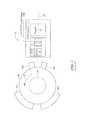
- FIG. 6is a pictorial showing a CVH sensing element proximate to circular magnet having two poles
- FIG. 6Ais a pictorial showing a CVH sensing element proximate to circular magnet having two poles but in a different arrangement than the arrangement of FIG. 6 ;
- FIG. 7is a pictorial showing another CVH sensing element proximate to circular magnet having two poles and showing the circular magnet in rotation;
- FIG. 8is a graph showing a magnetic flux as may be experienced by the CVH sensing element of FIG. 7 as the magnet rotates through one revolution;
- FIG. 9is a graph showing a linear output signal that may be generated from the CVH sensing element of FIG. 7 as the magnet rotates through one revolution, showing thresholds that may be applied to the linear output signal, and showing a TPOS output signal that can be generated in conjunction with the thresholds;
- FIG. 10is a block diagram showing a CVH sensing element, an angle detection circuit, a threshold processor, a memory to hold threshold value used by the threshold processor, a rotation direction processor, a rotation speed processor, and an output protocol processor; and
- FIG. 11is a flow chart showing a process that may be used by the threshold processor of FIG. 10 .
- magnetic field sensing elementis used to describe a variety of electronic elements that can sense a magnetic field.
- the magnetic field sensing elementscan be, but are not limited to, Hall effect elements, magnetoresistance elements, or magnetotransistors.
- Hall effect elementsfor example, a planar Hall element, a vertical Hall element, and a circular Hall element.
- magnetoresistance elementsfor example, a giant magnetoresistance (GMR) element, an anisotropic magnetoresistance element (AMR), a tunneling magnetoresistance (TMR) element, an Indium antimonide (InSb) sensor, and a magnetic tunnel junction (MTJ).
- GMRgiant magnetoresistance
- AMRanisotropic magnetoresistance element
- TMRtunneling magnetoresistance
- InSbIndium antimonide
- MTJmagnetic tunnel junction
- a so-called “circular vertical Hall” (CVH) sensing elementwhich includes a plurality of vertical magnetic field sensing elements, is known and described in PCT Patent Application No. PCT/EP2008056517, entitled “Magnetic Field Sensor for Measuring Direction of a Magnetic Field in a Plane,” filed May 28, 2008, and published in the English language as PCT Publication No. WO 2008/145662, which application and publication thereof are incorporated by reference herein in their entirety.
- the CVH sensing elementincludes a circular arrangement of vertical Hall elements arranged over a common circular implant region in a substrate.
- the CVH sensing elementcan be used to sense a direction (and optionally a strength) of a magnetic field in a plane of the substrate.
- some of the above-described magnetic field sensing elementstend to have an axis of maximum sensitivity parallel to a substrate that supports the magnetic field sensing element, and others of the above-described magnetic field sensing elements tend to have an axis of maximum sensitivity perpendicular to a substrate that supports the magnetic field sensing element.
- planar Hall elementstend to have axes of sensitivity perpendicular to a substrate
- magnetoresistance elements and vertical Hall elementsincluding circular vertical Hall (CVH) sensing elements
- a magnetic field sensoris described below that can replicate signals generated by a conventional “true power on state” (TPOS) detector as used in an automobile.
- TPOStrue power on state
- the same techniques and similar circuitscan be used to replicate any conventional signal representative of a rotation of an object, in an automobile or in other applications.
- TPOS camexamples below describe a particular TPOS cam as may be used upon an engine camshaft target object.
- similar circuits and techniquescan be used with other cams or gears disposed upon the engine camshaft, or upon other rotating parts of an engine (e.g., crank shaft, transmission gear, anti-lock braking system (ABS)), or upon rotating parts of a device that is not an engine.
- ABSanti-lock braking system
- an exemplary TPOS detector arrangement 10includes a TPOS detector 12 .
- the TPOS detector 12includes a magnetic field sensing circuit 14 having a magnetic field sensing element 16 coupled to an electronic circuit 18 .
- the TPOS detector 12can also include a magnet 20 .
- the magnet 20is configured to generate a magnetic field directed along an axis 22 .
- the electronic circuit 18is configured to generate a TPOS output signal 24 .
- the TPOS detector arrangement 10can also include a TPOS cam 26 having features 26 a , 26 b , 26 c , 26 d .
- the TPOS cam 26can be disposed, for example, upon a shaft 30 (i.e., a target object) configured to rotate in a direction 32 .
- the cam features 26 a , 26 b , 26 c , 26 dmodulate the magnetic field generated by the magnet 20 . Modulations of the magnetic field generated by the magnet 20 are sensed by the magnetic field sensing element 16 and result in state transitions in the TPOS output signal 24 .
- the TPOS detector 12being able to provide the TPOS output signal 24 having transitions after only a small number of degrees of rotation of the TPOS cam 26 , which can be interpreted by the engine control computer to generate an absolute angle of rotation of the TPOS cam 26 and of the shaft 30 upon which the TPOS cam 26 is disposed.
- a graph 60has a horizontal axis with a scale in units of target object rotation angle, for example, from 0 to 360 degrees.
- the graph 60also includes a vertical axis having a scale with units of volts in arbitrary units.
- a signal 62can be the same as or similar to the TPOS output signal 24 of FIG. 1 generated by the conventional TPOS detector 12 .
- the signal 62can include periods 64 a , 64 b , 64 c , 64 d in which the signal 62 is in a high state and periods 66 a , 66 b , 66 c , 66 d in which the signal 62 is in a low state.
- the high state periods 64 a , 64 b , 64 c , 64 d of the signal 62correspond to the features 26 a , 26 b , 26 c , 26 d of the TPOS cam 26 of FIG. 1 as they pass by the magnetic field sensing element 16 of FIG. 1 as the TPOS cam 26 rotates.
- an absolute angle of rotation of the cam 26 of FIG. 1corresponding to and beginning at any point (angle) along the horizontal axis of FIG. 2
- an absolute angle of rotation of the cam 26 of FIG. 1can be identified with only a small rotation of the cam 26 of FIG. 1 , i.e., as edges of the features 26 a - 26 d pass by the magnetic field sensing element 16 .
- the conventional TPOS detectore.g., 12 of FIG. 1
- the conventional TPOS detectoris only able to identify if it is over a cam tooth or valley, and is unable to identify an absolute or relative angle of rotation.
- a graph 50includes a horizontal axis having a scale in units of target object rotation angle, for example, from 0 to 360 degrees.
- the graph 50also includes a vertical scale having a scale with units of volts in arbitrary units.
- a signal 52is representative of an output signal that may be generated by an angle sensor that has a linear relationship with respect to angle of rotation from zero to three hundred sixty degrees.
- a plurality of thresholdsis shown along the vertical axis.
- the signal 52is represented as an analog signal and the thresholds are represented as analog values, it should be appreciated that the signal 52 could instead be comprised of successive digital values and the thresholds could be comprised of digital values.
- the linear signal 52can be compared against the thresholds as a target object rotates.
- the signal 62 of FIG. 2can be generated by comparison of the signal 52 with the thresholds shown along the vertical axis of FIG. 3 .
- the signal 52which ramps from zero volts up to a positive voltage as a target object rotates from zero to three hundred sixty degrees, repeats again in a region 52 a starting from three hundred sixty degrees and continuing to seven hundred twenty degrees.
- the signal 52repeats the saw tooth pattern as the target object rotates.
- linear signal 52is shown, in other embodiments, a signal that is nonlinear with respect to rotational angle can also be used and can be compared with other thresholds.
- a circular vertical Hall (CVH) sensing element 72includes a circular implant region 78 having a plurality of vertical Hall elements disposed thereon, of which a vertical Hall element 72 a is but one example.
- Each vertical Hall elementhas a plurality of Hall element contacts (e.g., four, five, or six contacts), of which a vertical Hall element contact 72 a a is but one example.
- a particular vertical Hall element (e.g., 72 a ) within the CVH sensing element 72which, for example, can have five adjacent contacts, can share some, for example, four, of the five contacts with a next vertical Hall element (e.g., 72 b ).
- the next vertical Hall elemente.g., 72 b
- the number of vertical Hall elementsis equal to the number of vertical Hall element contacts, e.g., 32.
- a different next vertical Hall elementcan be shifted by more than one contact from the prior vertical Hall element, in which case, there are fewer vertical Hall elements than there are vertical Hall element contacts in the CVH sensing element.
- a center of a vertical Hall element 0is positioned along an x-axis 80 and a center of vertical Hall element 8 is positioned along a y-axis 82 .
- a CVH sensing elementcan have more than or fewer than thirty-two vertical Hall elements and more than or fewer than thirty-two vertical Hall element contacts.
- a circular magnet 74 having a north side 74 a and a south side 74 bcan be disposed over the CVH 72 .
- the circular magnet 74tends to generate a magnetic field 76 having a direction from the south side 74 b to the north side 74 a , here shown to be pointed to a direction of about forty-five degrees relative to x-axis 80 .
- the circular magnet 74is mechanically coupled to a rotating target object, for example, to an automobile camshaft, and is subject to rotation relative to the CVH sensing element 72 .
- the CVH sensing element 72in combination with an electronic circuit described below can generate a signal related to the angle of rotation of the magnet 74 .
- the output signalhas a linear relationship with the angle. In some other embodiments, the output signal has a nonlinear relationship with the angle.
- a plurality of magnetic field sensing elements 90 a - 90 hcan be any type of magnetic field sensing elements, for example, vertical Hall sensing elements or magnetoresistance sensing elements. These elements can also be coupled to an electronic circuit. There can also be a magnet the same as or similar to the magnet 74 of FIG. 4 , disposed proximate to the sensing elements 80 a - 80 h.
- a graph 100has a horizontal axis with a scale in units of CVH vertical Hall element position, n, around a CVH sensing element, for example, the CVH sensing element 72 of FIG. 4 .
- the graph 100also has a vertical axis with a scale in units of millivolts.
- the vertical axisis representative of output signal levels from the plurality of vertical Hall elements of the CVH sensing element.
- the graph 100includes a signal 102 representative of output signal levels from the plurality of vertical Hall elements of the CVH sensing element taken with the magnetic field of FIG. 1 pointing in a direction of forty-five degrees.
- vertical Hall element 0is centered along the x-axis 80 and vertical Hall element 8 is centered along the y-axis 82 .
- the exemplary CVH sensing element 72there are thirty-two vertical Hall element contacts and a corresponding thirty-two vertical Hall elements, each vertical Hall element having a plurality of vertical Hall element contacts, for example, five contacts.
- a maximum positive signalis achieved from a vertical Hall element centered at position 4 , which is aligned with the magnetic field 76 of FIG. 4 .
- a maximum negative signalis achieved from a vertical Hall element centered at position 20 , which is also aligned with the magnetic field 76 of FIG. 1 .
- a sine wave 104is provided to more clearly show the ideal behavior of the signal 102 .
- the signal 102has variations due to vertical Hall element offsets, which tend to somewhat randomly cause element output signals to be too high or too low relative to the sine wave 104 , in accordance with offset errors for each element.
- the offset signal errorsare undesirable.
- groups of contacts of each vertical Hall elementcan be used in a multiplexed or chopped arrangement to generate chopped output signals from each vertical Hall element. Thereafter, a new group of adjacent vertical Hall element contacts can be selected (i.e., a new vertical Hall element), which can be offset by one element from the prior group. The selected new group can be used in the multiplexed or chopped arrangement to generate another chopped output signal from the selected next group, and so on.
- Each step of the signal 102can be representative of a chopped output signal from one respective group of vertical Hall element contacts, i.e., from one respective vertical Hall element. However, in other embodiments, no chopping is performed and each step of the signal 102 is representative of an unchopped output signal from one respective group of vertical Hall element contacts, i.e., from one respective vertical Hall element. Thus, the signal 102 is representative of a CVH output signal with or without the above-described grouping and chopping of vertical Hall elements.
- a phase of the signal 102can be used to identify the pointing direction of the magnetic field 76 of FIG. 4 relative to the CVH lsensiong element 72 . It will also be understood that, unlike a conventional TPOS detector, the absolute and/or relative angle of rotation of a target object can be determined even when the target object is stationary. As described above, with a conventional TPOS detector, when the target object is stationary, it is only possible to identify if the TPOS detector is over a tooth or over a valley of the TPOS cam.
- a magnetic arrangement 110can include a circuit substrate 112 upon which a CVH sensing element 114 is disposed.
- the circuit substrate 112which includes the CVH sensing element 114 and other circuitry, forms a TPOS detector.
- a circular magnet 116 having north and south polescan be disposed proximate to the circuit substrate 112 .
- a center of the CVH sensing element 114is disposed at a position along an axis of rotation of the circular magnet 116 .
- another TPOS arrangement 120can include a circuit substrate 122 upon which a CVH sensing element 124 is disposed.
- the circuit substrate 122which includes the CVH sensing element 124 and other circuitry, forms a TPOS detector.
- a circular magnet 126 having north and south polescan be disposed proximate to the circuit substrate 122 .
- the CVH sensing element 124is disposed in a plane parallel to a plane of a major surface of the circular magnet 126 .
- respective CVH sensing elements 114 , 124are responsive to a rotation angle of a respective one of the circular magnets 116 , 126 .
- yet another TPOS arrangement 130can include a circuit substrate 132 upon which a CVH sensing element 134 is disposed.
- the circuit substrate 132which includes the CVH sensing element 134 and other circuitry, forms a TPOS detector.
- a circular magnet 136 having north and south polescan be disposed proximate to the circuit substrate 132 .
- the magnet 136can be coupled to an end of a shaft (not shown), i.e., a target object, which is configured to rotate as indicated by an arrow 138 .
- a graph 140includes horizontal axis with a scale in units of rotational angle of the magnet 136 of FIG. 7 from zero to three hundred sixty degrees.
- the graph 140also includes a vertical axis with a scale corresponding to magnetic flux in arbitrary units.
- a signal 142is representative of magnetic flux experienced by the CVH sensing element 134 as the magnet 136 rotates.
- a graph 150includes horizontal axis with a scale in units of rotation angle of the magnet 136 of FIG. 7 from zero to three hundred sixty degrees.
- the graph 150also includes a vertical axis having a scale in units of volts in arbitrary units.
- a signal 152is representative of a processed output signal as may be generated by the TPOS detector 132 of FIG. 7 as the magnet 136 rotates.
- a plurality of threshold values 154 a , 154 b , 154 c , 154 d , 154 e , 154 f , 154 g , 154 hcan be compared with the signal 152 .
- a signal 156which can be the same as or similar to the signal 62 of FIG.
- the signal 156can be generated without a TPOS cam, such as the TPOS cam 26 of FIG. 1 coupled to the target object, but instead, with a magnetic, e.g., the magnet 136 of FIG. 7 , coupled to the target object.
- the signal 156can be generated using only the rotating magnet 136 of FIG. 7 in conjunction with an angle sensor such as the CVH sensing element 134 of FIG. 7 .
- a TPOS detector 170can include a CVH sensing element 172 having a plurality of vertical Hall elements, each vertical Hall element comprising a group of vertical Hall element contacts (e.g., five vertical Hall element contacts), of which a vertical Hall element contact 173 is but one example.
- the TPOS detector 170is responsive to a magnet (not shown), which can be the same as or similar to the magnet 74 of FIG. 4 .
- the magnetcan be coupled to a target object (not shown), for example, a camshaft on an engine.
- the CVH output signal 172 acan be the same as or similar to the signal 102 of FIG. 5 .
- the CVH output signal 172 ais comprised of sequential output signals taken one-at-a-time around the CVH sensing element 172 , wherein each output signal is generated on the same signal path.
- the number of vertical Hall elements (each comprising a group of vertical Hall element contacts) in the CVH sensing element 172is equal to the total number of sensing element positions, N.
- the CVH output signal 172 acan be comprised of sequential output signals, wherein each one of the CVH output signals 172 a is associated with a respective one of the vertical Hall elements in the CVH sensing element 172 , i.e., the circuit 100 steps around the vertical Hall elements of the CVH sensing element 172 by increments of one, and N equals the number of vertical Hall elements in the CVH sensing element 172 .
- the incrementscan be by greater than one vertical Hall element, in which case N is less than the number of vertical Hall elements in the CVH sensing element 172 .
- Nthirty-two vertical Hall elements
- the increments of vertical Hall element positions, ncan be greater than one vertical Hall element contact.
- another switching circuit 176can provide the above-described “chopping” of groups of the vertical Hall elements within the CVH sensing element 172 .
- choppingwill be understood to be an arrangement in which a group of vertical Hall element contacts, for example, five vertical Hall element contacts, are driven with current sources 184 , 186 in a plurality of connection configurations, and signals are received from the group of vertical Hall element contacts in corresponding configurations.
- nthere can be a plurality of output signals during the chopping, and then the group increments to a new group, for example, by an increment of one vertical Hall element contact.
- the circuit 170can include an oscillator 178 that generates clock signals 178 a , 178 b , which can have the same or different frequencies.
- a divider 180is coupled to receive the clock signal 178 a and configured to generate a divided clock signal 180 a .
- a switch control circuit 182is coupled to receive the divided clock signal 180 a and configured to generate switch control signals 182 a , which are received by the switching circuits 174 , 176 to control the sequencing around the CVH sensing element 172 , and, optionally, to control chopping of groups of vertical Hall elements within the CVH sensing element 172 in ways described above.
- the circuit 170can include a divider 202 coupled to receive the clock signal 178 c and configured to generate a divided clock signal 202 a.
- the TPOS detector 170can include an angle detection circuit 188 coupled to receive the signal 172 a representative of signals generated by the CVH sensing element 172 .
- An amplifier 190can be coupled to receive the output signal 172 a and configured to generate an amplified signal 190 a .
- a bandpass filter 192can be coupled to receive the amplified signal 190 a and configured to generate a filtered signal 192 a . It will be understood that the filtered signal 192 a is like the signal 102 of FIG. 5 , but filtered, thereby having steps smaller than the steps of the signal 102 .
- a comparator 194can be coupled to receive the filtered signal 192 a .
- the comparator 194can also be coupled to receive a threshold signal 200 .
- the comparator 194can be configured to generate a comparison signal 194 a by comparing the filtered signal 192 a with the threshold signal 200 .
- a countercan be coupled to receive the clock signal 178 b at a clock input, coupled to receive the comparison signal 194 a at an enable input, and coupled to receive the clock signal 202 a at a reset input.
- the counter 196is configured to generate a count signal 196 a , which is a digital signal.
- the count signal 196 ais representative of a phase between the comparison signal 194 a and the clock signal 178 b.
- a latch 198can be coupled to receive the count signal 196 a at a data input and coupled to receive the clock signal 202 a at a clock input.
- the latch 198can be configured to generate a latched signal 198 a , also referred to herein as an x-y angle signal.
- the latched signal 198 ais a digital signal representative of an angle of a direction of a magnetic field experienced by the CVH sensing element 172 , i.e. an angle of the target object to which the magnet is coupled.
- the latched signal 198 a(x-y angle signal) is a digital signal having values that are linearly related to an angle of rotation of a direction of the magnetic field experienced by the CVH sensing element 172 , i.e., and angle of rotation of the target object.
- the digital values of the latched signal 198 a acan be represented graphically like the signal 152 of FIG. 9 .
- the latched signal 198 ais a digital signal having values that are not linearly related to an angle of rotation of a direction of the magnetic field experienced by the CVH sensing element 172 .
- the TPOS detector 170can also include a thresholding processor 204 coupled to receive the latched signal 198 a .
- the thresholding processor 204can also be coupled to receive threshold values 216 a from a threshold memory device 216 .
- the threshold values 216 acan be like the threshold values 154 a , 154 b , 154 c , 154 d , 154 e , 154 f , 154 g , 154 h shown in FIG. 9 and like the threshold values shown on the vertical axis of FIG. 3 .
- the thresholding processor 204can be configured to compare the latched signal 198 a the threshold values 216 a .
- the comparingis described in further detail below in conjunction with FIG. 11 .
- the thresholding processor 204can be configured to generate a thresholded signal 204 a , which can be the same as or similar to the TPOS signal 156 of FIG. 9 and the same as or similar to the TPOS signal 62 of FIG. 2 .
- the TPOS detector 170can generate the thresholded signal 204 a the same as or similar to a conventional TPOS signal like the conventional TPOS signal 62 of FIG. 2 generated by the conventional TPOS detector 12 of FIG. 1 .
- the TPOS detector 170can also include a rotation direction processor 206 coupled to receive the latched signal 198 a (x-y angle signal).
- the rotation direction processor 206can identify a direction of rotation of the angle of the magnetic field experienced by the CVH sensing element 172 .
- the magnetic field sensor 170provides the x-y angle signal 198 a having values that are linearly related to an angle of rotation of a direction of the magnetic field experienced by the CVH sensing element 172 , i.e., an angle of rotation of the target object, identification of the direction of rotation is straightforward.
- the rotation direction processor 206is configured to generate a rotation direction output signal 206 a indicative of the direction of rotation of the target object.
- the TPOS detector 170can also include a rotation speed processor 208 coupled to receive the x-y angle signal 198 a .
- the rotation speed processor 208can identify a speed of rotation of the angle of the magnetic field experienced by the CVH sensing element 172 .
- the magnetic field sensor 170provides the x-y angle signal 198 a having values that are linearly related to an angle of rotation of a direction of the magnetic field experienced by the CVH sensing element 172 , i.e., an angle of rotation of the target object
- identification of the speed of rotationcan be obtained by comparing degrees of rotation to a frequency of a fixed clock signal (not shown). Knowing the number of clock cycles per degree of rotation can yield a simple mathematical solution for speed of rotation.
- the rotation speed processor 208is configured to generate a rotation speed output signal 208 a indicative of the speed of rotation of the target object.
- the TPOS detector 170can also include an output protocol processor 210 coupled to receive at least one of the latched signal 198 a (the x-y angle signal), which is representative of an angle of the magnetic field experienced by the CVH sensing element 172 (i.e., an angle of rotation of the target object), the thresholded signal 204 a , which is the same as or similar to the TPOS signal 156 of FIG. 9 , the rotation direction output signal 206 a , or the rotation speed signal 208 a .
- the latched signal 198 athe x-y angle signal
- the thresholded signal 204 awhich is the same as or similar to the TPOS signal 156 of FIG. 9
- the rotation direction output signal 206 athe rotation direction output signal 206 a
- the rotation speed signal 208 athe rotation speed signal
- the output protocol processor 210can be configured to reformat one or more of the above-mentioned signals to generate an output signal 212 in a format, for example, a SENT format, an I2C format, a pulse width modulated (PWM) format, and a VDA format.
- a formatfor example, a SENT format, an I2C format, a pulse width modulated (PWM) format, and a VDA format.
- PWMpulse width modulated
- the output protocol processor 210can also be configured to receive a command signal 212 , which can include threshold values 214 received by the threshold memory device 216 for storage. With this arrangement a user of the TPOS detector 170 can send threshold values to the TPOS detector 170 , resulting in selection of edge positions of the thresholded signal 204 a.
- the magnetic field sensor 170is shown to have a CVH sensing element 172 , which can be the same as or similar to the CVH sensing element 72 of FIG. 4 , in other embodiments, the CVH sensing element 172 can be replaced by a plurality of magnetic field sensing elements, for example, the plurality of magnetic field sensing elements 90 a - 90 h of FIG. 4 A.
- the plurality of magnetic field sensing elements 90 a - 90 h of FIG. 4 AOne of ordinary skill in the art will understand how to modify some of the front end sections of the magnetic field sensor 170 to use magnetoresistance elements, or other types of magnetic field sensing elements described in conjunction with FIG. 4A .
- FIG. 11shows a flowchart corresponding to the below contemplated technique which would be implemented in the thresholding processor 204 of FIG. 10 .
- Rectangular elements(typified by element 252 in FIG. 11 ), herein denoted “processing blocks,” represent computer software instructions or groups of instructions.
- Diamond shaped elements(typified by element 256 in FIG. 11 ), herein denoted “decision blocks,” represent computer software instructions, or groups of instructions, which affect the execution of the computer software instructions represented by the processing blocks.
- the processing and decision blocksrepresent steps performed by functionally equivalent circuits such as a digital signal processor circuit or an application specific integrated circuit (ASIC).
- ASICapplication specific integrated circuit
- the flow diagramsdo not depict the syntax of any particular programming language. Rather, the flow diagrams illustrate the functional information one of ordinary skill in the art requires to fabricate circuits or to generate computer software to perform the processing required of the particular apparatus. It should be noted that many routine program elements, such as initialization of loops and variables and the use of temporary variables are not shown. It will be appreciated by those of ordinary skill in the art that unless otherwise indicated herein, the particular sequence of blocks described is illustrative only and can be varied without departing from the spirit of the invention. Thus, unless otherwise stated the blocks described below are unordered meaning that, when possible, the steps can be performed in any convenient or desirable order.
- a process 250can be used by the thresholding processor 204 of FIG. 10 .
- the process 250begins at box 252 , where angle threshold values are received by the thresholding processor 204 of FIG. 10 , for example, angle threshold values 216 a of FIG. 10 .
- angle signal valuesare received by the thresholding processor 204 , for example, angle signal values within the latched signal 198 a of FIG. 10 .
- received angle signal valuesare compared with received angle threshold values. If, at box 256 , the angle signal value is not between first and second threshold values, the process proceeds to box 258 .
- the first and second threshold valuescan be, for example, the lowest two threshold values shown along the vertical axis of FIG. 3 .
- an output signal valueis set to be low.
- the thresholded signal 204 a of FIG. 10can be set to a low state.
- the threshold pair used at box 256is a last threshold pair. If the threshold pair is not the last threshold pair, then at box 262 , another threshold pair is selected. For example, third and fourth thresholds along the vertical axis of FIG. 3 can be selected at box 262 . The process then returns to box 256 .
- the processproceeds to box 264 .
- the output signal valueis set to be high.
- the thresholded signal 204 a of FIG. 10can be set to a high state.
- the processthen returns to box 254 where a next angle signal value is received.
- TPOS camWhile a TPOS cam is described above that has four teeth or features, a TPOS cam with more than or fewer than four features can also be used. In general, the number of teeth is represented by the same number of thresholds (see, e.g., FIGS. 2 and 3 .
- the sensed object upon the target objectcan instead be a gear with any number of regularly spaced teeth, and/or with any number of irregularly spaced teeth.
- the number of teethis represented by the same number of thresholds (see, e.g., FIGS. 2 and 3 ).
Landscapes
- Physics & Mathematics (AREA)
- General Physics & Mathematics (AREA)
- Condensed Matter Physics & Semiconductors (AREA)
- Transmission And Conversion Of Sensor Element Output (AREA)
- Measurement Of Length, Angles, Or The Like Using Electric Or Magnetic Means (AREA)
- Measuring Magnetic Variables (AREA)
Abstract
Description
Claims (28)
Priority Applications (6)
| Application Number | Priority Date | Filing Date | Title |
|---|---|---|---|
| US13/413,037US9182456B2 (en) | 2012-03-06 | 2012-03-06 | Magnetic field sensor for sensing rotation of an object |
| PCT/US2013/020965WO2013133908A1 (en) | 2012-03-06 | 2013-01-10 | Magnetic field sensor for sensing rotation of an object |
| JP2014560913AJP6180447B2 (en) | 2012-03-06 | 2013-01-10 | Magnetic field sensor for detecting the rotation of an object |
| EP13702526.8AEP2823259B1 (en) | 2012-03-06 | 2013-01-10 | Magnetic field sensor for sensing rotation of an object |
| KR1020147027901AKR102043035B1 (en) | 2012-03-06 | 2013-01-10 | Magnetic field sensor for sensing rotation of an object |
| TW102101988ATWI471580B (en) | 2012-03-06 | 2013-01-18 | Magnetic field sensor for sensing a position of an object and a method used in the magnetic field sensor |
Applications Claiming Priority (1)
| Application Number | Priority Date | Filing Date | Title |
|---|---|---|---|
| US13/413,037US9182456B2 (en) | 2012-03-06 | 2012-03-06 | Magnetic field sensor for sensing rotation of an object |
Publications (2)
| Publication Number | Publication Date |
|---|---|
| US20130238278A1 US20130238278A1 (en) | 2013-09-12 |
| US9182456B2true US9182456B2 (en) | 2015-11-10 |
Family
ID=47633558
Family Applications (1)
| Application Number | Title | Priority Date | Filing Date |
|---|---|---|---|
| US13/413,037Active2034-08-08US9182456B2 (en) | 2012-03-06 | 2012-03-06 | Magnetic field sensor for sensing rotation of an object |
Country Status (6)
| Country | Link |
|---|---|
| US (1) | US9182456B2 (en) |
| EP (1) | EP2823259B1 (en) |
| JP (1) | JP6180447B2 (en) |
| KR (1) | KR102043035B1 (en) |
| TW (1) | TWI471580B (en) |
| WO (1) | WO2013133908A1 (en) |
Cited By (10)
| Publication number | Priority date | Publication date | Assignee | Title |
|---|---|---|---|---|
| US20140225596A1 (en)* | 2013-02-12 | 2014-08-14 | Asahi Kasei Microdevices Corporation | Rotation angle measurement apparatus |
| US20150198677A1 (en)* | 2014-01-14 | 2015-07-16 | Allegro Microsystems, Llc | Circuit and Method for Reducing an Offset Component of a Plurality of Vertical Hall Elements Arranged in a Circle |
| US10151606B1 (en) | 2016-02-24 | 2018-12-11 | Ommo Technologies, Inc. | Tracking position and movement using a magnetic field |
| US10276289B1 (en) | 2018-06-01 | 2019-04-30 | Ommo Technologies, Inc. | Rotating a permanent magnet in a position detection system |
| US10578679B2 (en) | 2018-06-18 | 2020-03-03 | Allegro Microsystems, Llc | Magnetic field sensors having virtual signals |
| US10598739B2 (en) | 2018-06-18 | 2020-03-24 | Allegro Microsystems, Llc | Magnetic field sensors having virtual signals |
| US10866118B2 (en) | 2018-06-18 | 2020-12-15 | Allegro Microsystems, Llc | High resolution magnetic field sensors |
| US10908229B2 (en) | 2018-06-18 | 2021-02-02 | Allegro Microsystems, Llc | Regulation of coefficients used in magnetic field sensor virtual signal generation |
| US11762043B2 (en) | 2021-03-11 | 2023-09-19 | Allegro Microsystems, Llc | High resolution magnetic field sensors |
| US11802922B2 (en) | 2021-01-13 | 2023-10-31 | Allegro Microsystems, Llc | Circuit for reducing an offset component of a plurality of vertical hall elements arranged in one or more circles |
Families Citing this family (22)
| Publication number | Priority date | Publication date | Assignee | Title |
|---|---|---|---|---|
| US8729890B2 (en) | 2011-04-12 | 2014-05-20 | Allegro Microsystems, Llc | Magnetic angle and rotation speed sensor with continuous and discontinuous modes of operation based on rotation speed of a target object |
| US8793085B2 (en)* | 2011-08-19 | 2014-07-29 | Allegro Microsystems, Llc | Circuits and methods for automatically adjusting a magnetic field sensor in accordance with a speed of rotation sensed by the magnetic field sensor |
| US9488498B2 (en) | 2014-03-21 | 2016-11-08 | Infineon Technologies Ag | Cam shaft rotation sensor |
| US11125768B2 (en)* | 2014-06-17 | 2021-09-21 | Infineon Technologies Ag | Angle based speed sensor device |
| US10222234B2 (en)* | 2014-06-17 | 2019-03-05 | Infineon Technologies Ag | Rotation sensor |
| CN106489065B (en)* | 2014-06-30 | 2019-02-05 | 广濑电机株式会社 | motion detection device |
| US9739637B2 (en)* | 2014-10-31 | 2017-08-22 | Allegro Microsystems, Llc | Magnetic field motion sensor and related techniques |
| US9823092B2 (en)* | 2014-10-31 | 2017-11-21 | Allegro Microsystems, Llc | Magnetic field sensor providing a movement detector |
| WO2017090153A1 (en)* | 2015-11-26 | 2017-06-01 | 三菱電機株式会社 | Angle detection device and electric power steering device |
| KR101886362B1 (en)* | 2017-05-19 | 2018-08-09 | 주식회사 동운아나텍 | An actuator motion sensing element and a flexible circuit board |
| KR101886361B1 (en)* | 2017-05-26 | 2018-08-09 | 주식회사 동운아나텍 | Method for setting an id of a digital hall sensor |
| KR101973095B1 (en)* | 2017-05-31 | 2019-04-26 | 주식회사 동운아나텍 | Method for transmitting data in a camera module |
| CN109283355B (en)* | 2017-07-20 | 2022-07-01 | 英飞凌科技股份有限公司 | Angle-based speed sensor apparatus |
| CN108414785B (en)* | 2018-05-03 | 2024-07-12 | 苏州微测电子有限公司 | Sensor and detection device |
| DE102018215938B4 (en)* | 2018-09-19 | 2024-11-07 | Infineon Technologies Ag | high-resolution mode for a magnetic field sensor |
| US10823586B2 (en) | 2018-12-26 | 2020-11-03 | Allegro Microsystems, Llc | Magnetic field sensor having unequally spaced magnetic field sensing elements |
| JP7260321B2 (en)* | 2019-02-15 | 2023-04-18 | エイブリック株式会社 | magnetic sensor circuit |
| US11016150B2 (en)* | 2019-06-03 | 2021-05-25 | Honeywell International Inc. | Method, apparatus and system for detecting stray magnetic field |
| TWI716086B (en)* | 2019-08-23 | 2021-01-11 | 和旺昌噴霧股份有限公司 | Flowmeter |
| US11280637B2 (en) | 2019-11-14 | 2022-03-22 | Allegro Microsystems, Llc | High performance magnetic angle sensor |
| US11237020B2 (en) | 2019-11-14 | 2022-02-01 | Allegro Microsystems, Llc | Magnetic field sensor having two rows of magnetic field sensing elements for measuring an angle of rotation of a magnet |
| CN115541920B (en)* | 2022-10-25 | 2025-09-26 | 重庆睿歌微电子有限公司 | Wheel speed sensor chip and control method thereof |
Citations (61)
| Publication number | Priority date | Publication date | Assignee | Title |
|---|---|---|---|---|
| JPS5855688A (en) | 1981-09-28 | 1983-04-02 | Kawasaki Heavy Ind Ltd | Heat accumulating system utilizing hydrogenated metal |
| JPS58193403A (en) | 1982-04-24 | 1983-11-11 | Hitachi Constr Mach Co Ltd | Angle detecting device |
| US4668914A (en) | 1983-12-23 | 1987-05-26 | International Standard Electric Corporation | Circular, amorphous metal, Hall effect magnetic field sensor with circumferentially spaced electrodes |
| US4761569A (en) | 1987-02-24 | 1988-08-02 | Sprague Electric Company | Dual trigger Hall effect I.C. switch |
| US4829352A (en) | 1986-04-29 | 1989-05-09 | Lgz Landis & Gyr Zug Ag | Integrable Hall element |
| US5055781A (en) | 1989-05-13 | 1991-10-08 | Aisan Kogyo Kabushiki Kaisha | Rotational angle detecting sensor having a plurality of magnetoresistive elements located in a uniform magnetic field |
| US5541506A (en) | 1993-10-28 | 1996-07-30 | Nippondenso Co., Ltd. | Rotational position detector having initial setting function |
| US5572058A (en) | 1995-07-17 | 1996-11-05 | Honeywell Inc. | Hall effect device formed in an epitaxial layer of silicon for sensing magnetic fields parallel to the epitaxial layer |
| US5612618A (en) | 1994-10-06 | 1997-03-18 | Nippondenso Co., Ltd. | Rotational position detecting device having peak and bottom hold circuits |
| US5619137A (en) | 1996-02-12 | 1997-04-08 | Allegro Microsystems, Inc. | Chopped low power magnetic-field detector with hysteresis memory |
| US5621319A (en) | 1995-12-08 | 1997-04-15 | Allegro Microsystems, Inc. | Chopped hall sensor with synchronously chopped sample-and-hold circuit |
| US5657189A (en) | 1994-09-19 | 1997-08-12 | Fujitsu Limited | Hall-effect magnetic sensor and a thin-film magnetic head using such a hall-effect magnetic sensor |
| US5694038A (en) | 1996-01-17 | 1997-12-02 | Allegro Microsystems, Inc. | Detector of passing magnetic articles with automatic gain control |
| WO1998010302A2 (en) | 1996-09-09 | 1998-03-12 | Physical Electronics Laboratory | Method for reducing the offset voltage of a hall device |
| US5831513A (en) | 1997-02-04 | 1998-11-03 | United Microelectronics Corp. | Magnetic field sensing device |
| US5844411A (en) | 1995-05-31 | 1998-12-01 | Borg-Warner Automotive, Inc. | Diagnostic detection for hall effect digital gear tooth sensors and related method |
| WO1998054547A1 (en) | 1997-05-29 | 1998-12-03 | Laboratorium Für Physikalische Elektronik | Magnetic rotation sensor |
| US5942895A (en) | 1995-10-30 | 1999-08-24 | Sentron Ag | Magnetic field sensor and current and/or energy sensor |
| WO2000002266A1 (en) | 1998-07-02 | 2000-01-13 | Austria Mikro Systeme International (Ams) | Integrated hall device |
| US6064199A (en) | 1998-02-23 | 2000-05-16 | Analog Devices, Inc. | Magnetic field change detection circuitry having threshold establishing circuitry |
| US6064202A (en) | 1997-09-09 | 2000-05-16 | Physical Electronics Laboratory | Spinning current method of reducing the offset voltage of a hall device |
| US6091239A (en) | 1996-01-17 | 2000-07-18 | Allegro Microsystems, Inc. | Detection of passing magnetic articles with a peak referenced threshold detector |
| US6100680A (en) | 1996-01-17 | 2000-08-08 | Allegro Microsystems, Inc. | Detecting the passing of magnetic articles using a transducer-signal detector having a switchable dual-mode threshold |
| US6166535A (en) | 1997-09-05 | 2000-12-26 | Hella Kg Hueck & Co. | Inductive angle sensor that adapts an oscillator frequency and phase relationship to that of an interference frequency |
| US6232768B1 (en) | 1996-01-17 | 2001-05-15 | Allegro Microsystems Inc. | Centering a signal within the dynamic range of a peak detecting proximity detector |
| US6236199B1 (en) | 1997-09-05 | 2001-05-22 | Hella Kg Hueck & Co. | Inductive angle sensor |
| US6265864B1 (en) | 1999-02-24 | 2001-07-24 | Melexis, N.V. | High speed densor circuit for stabilized hall effect sensor |
| US6356741B1 (en) | 1998-09-18 | 2002-03-12 | Allegro Microsystems, Inc. | Magnetic pole insensitive switch circuit |
| EP0631416B1 (en) | 1993-06-28 | 2002-09-18 | Nec Corporation | Foldable portable telephone set |
| JP2003042709A (en) | 2001-07-30 | 2003-02-13 | Aisin Seiki Co Ltd | Angle sensor |
| US6525531B2 (en) | 1996-01-17 | 2003-02-25 | Allegro, Microsystems, Inc. | Detection of passing magnetic articles while adapting the detection threshold |
| US6542068B1 (en) | 1998-04-27 | 2003-04-01 | Myonic Ag | Vertical hall effect sensor and a brushless electric motor having a vertical hall effect sensor |
| US6545462B2 (en) | 2000-08-21 | 2003-04-08 | Sentron Ag | Sensor for the detection of the direction of a magnetic field having magnetic flux concentrators and hall elements |
| WO2003036732A2 (en) | 2001-10-16 | 2003-05-01 | Fraunhofer Gesellschaft Zur Förderung Der Angewandten Forschung E. V. | Compact vertical hall sensor |
| EP0875733B1 (en) | 1997-04-28 | 2004-03-03 | Allegro Microsystems Inc. | Detection of passing magnetic articles using a peak-on-peak percentage threshold detector |
| WO2004025742A1 (en) | 2002-09-10 | 2004-03-25 | Sentron Ag | Magnetic field sensor comprising a hall element |
| US6768301B1 (en) | 1999-09-09 | 2004-07-27 | Fraunhofer-Gesellschaft Zur Foerderung Der Angewandten Forschung E.V. | Hall sensor array for measuring a magnetic field with offset compensation |
| JP2005241269A (en) | 2004-02-24 | 2005-09-08 | Aisin Seiki Co Ltd | Angle sensor |
| US6969988B2 (en) | 2002-03-22 | 2005-11-29 | Asahi Kasei Emd Corporation | Angle determining apparatus and angle determining system |
| US7038448B2 (en) | 2001-05-25 | 2006-05-02 | Sentron Ag | Magnetic field sensor |
| WO2006056289A1 (en) | 2004-11-26 | 2006-06-01 | A. Raymond Et Cie | System for tightly covering a supporting element in the area of a recess |
| WO2006074989A2 (en) | 2005-01-11 | 2006-07-20 | Ecole Polytechnique Federale De Lausanne | Hall sensor and method of operating a hall sensor |
| US20060202291A1 (en)* | 2005-02-23 | 2006-09-14 | Stefan Kolb | Magnetoresistive sensor module and method for manufacturing the same |
| US7119538B2 (en) | 2003-03-26 | 2006-10-10 | Micronas Gmbh | Offset-reduced hall sensor |
| US7159556B2 (en) | 2004-09-09 | 2007-01-09 | Toyota Jidosha Kabushiki Kaisha | Control apparatus and method for internal combustion engine |
| US20070029998A1 (en) | 2003-08-22 | 2007-02-08 | Sentron Ag | Sensor for detecting the direction of a magnetic field in a plane |
| US20070149262A1 (en) | 2003-11-21 | 2007-06-28 | Nokia Corporation | Two step activation of phone |
| US7259556B2 (en) | 2002-08-01 | 2007-08-21 | Melexis Technologies Sa | Magnetic field sensor and method for operating the magnetic field sensor |
| DE102005014509B4 (en) | 2005-03-30 | 2007-09-13 | Austriamicrosystems Ag | Sensor arrangement and method for determining a rotation angle |
| DE102006037226A1 (en) | 2006-08-09 | 2008-02-14 | Fraunhofer-Gesellschaft zur Förderung der angewandten Forschung e.V. | Calibratable magnetic 3D-point sensor during measuring operation |
| US7362094B2 (en) | 2006-01-17 | 2008-04-22 | Allegro Microsystems, Inc. | Methods and apparatus for magnetic article detection |
| WO2008145662A1 (en) | 2007-05-29 | 2008-12-04 | Ecole Polytechnique Federale De Lausanne | Magnetic field sensor for measuring direction of a magnetic field in a plane |
| EP2000814A2 (en) | 2007-06-04 | 2008-12-10 | Melexis NV | Magnetic field orientation sensor |
| US20090174395A1 (en) | 2008-01-04 | 2009-07-09 | Thomas Monica J | Methods and apparatus for angular position sensing using multiple quadrature signals from frequency independent sinusoids |
| WO2009124969A1 (en) | 2008-04-08 | 2009-10-15 | Ecole Polytechnique Federale De Lausanne (Epfl) | Magnetic field sensor measuring a direction of a magnetic field in a plane and current sensor |
| JP2010014607A (en) | 2008-07-04 | 2010-01-21 | Aisin Seiki Co Ltd | Rotational angle detection apparatus |
| JP2010078366A (en) | 2008-09-24 | 2010-04-08 | Aisin Seiki Co Ltd | Angle detecting apparatus |
| US7714570B2 (en) | 2006-06-21 | 2010-05-11 | Allegro Microsystems, Inc. | Methods and apparatus for an analog rotational sensor having magnetic sensor elements |
| US20100156397A1 (en) | 2008-12-23 | 2010-06-24 | Hitoshi Yabusaki | Methods and apparatus for an angle sensor for a through shaft |
| US7746065B2 (en) | 2004-09-16 | 2010-06-29 | Liaisons Electroniques-Mecaniques Lem S.A. | Continuously calibrated magnetic field sensor |
| US8508218B2 (en)* | 2011-05-11 | 2013-08-13 | Sensima Technology Sa | Hall-effect-based angular orientation sensor and corresponding method |
Family Cites Families (8)
| Publication number | Priority date | Publication date | Assignee | Title |
|---|---|---|---|---|
| JP4591034B2 (en)* | 2004-10-18 | 2010-12-01 | 株式会社デンソー | Rotation angle detector |
| JP4737371B2 (en)* | 2004-11-18 | 2011-07-27 | Tdk株式会社 | Rotation angle detector |
| US6967477B1 (en)* | 2004-12-02 | 2005-11-22 | Honeywell International Inc. | Adaptive geartooth sensor with dual peak detectors and true power on capability |
| JP4655625B2 (en)* | 2004-12-24 | 2011-03-23 | 株式会社デンソー | Position detection device |
| JP4797581B2 (en)* | 2005-11-09 | 2011-10-19 | 株式会社デンソー | Rotation angle detector |
| KR100818143B1 (en)* | 2006-05-19 | 2008-03-31 | 노키아 코포레이션 | Two-speed mobile phone |
| JP2009002737A (en)* | 2007-06-20 | 2009-01-08 | Denso Corp | Rotation angle detector |
| JP5341714B2 (en)* | 2009-06-15 | 2013-11-13 | 愛三工業株式会社 | Phase difference type resolver |
- 2012
- 2012-03-06USUS13/413,037patent/US9182456B2/enactiveActive
- 2013
- 2013-01-10EPEP13702526.8Apatent/EP2823259B1/enactiveActive
- 2013-01-10JPJP2014560913Apatent/JP6180447B2/enactiveActive
- 2013-01-10WOPCT/US2013/020965patent/WO2013133908A1/enactiveApplication Filing
- 2013-01-10KRKR1020147027901Apatent/KR102043035B1/enactiveActive
- 2013-01-18TWTW102101988Apatent/TWI471580B/enactive
Patent Citations (78)
| Publication number | Priority date | Publication date | Assignee | Title |
|---|---|---|---|---|
| JPS5855688A (en) | 1981-09-28 | 1983-04-02 | Kawasaki Heavy Ind Ltd | Heat accumulating system utilizing hydrogenated metal |
| JPS58193403A (en) | 1982-04-24 | 1983-11-11 | Hitachi Constr Mach Co Ltd | Angle detecting device |
| US4668914A (en) | 1983-12-23 | 1987-05-26 | International Standard Electric Corporation | Circular, amorphous metal, Hall effect magnetic field sensor with circumferentially spaced electrodes |
| US4829352A (en) | 1986-04-29 | 1989-05-09 | Lgz Landis & Gyr Zug Ag | Integrable Hall element |
| US4761569A (en) | 1987-02-24 | 1988-08-02 | Sprague Electric Company | Dual trigger Hall effect I.C. switch |
| US5055781A (en) | 1989-05-13 | 1991-10-08 | Aisan Kogyo Kabushiki Kaisha | Rotational angle detecting sensor having a plurality of magnetoresistive elements located in a uniform magnetic field |
| EP0631416B1 (en) | 1993-06-28 | 2002-09-18 | Nec Corporation | Foldable portable telephone set |
| US5541506A (en) | 1993-10-28 | 1996-07-30 | Nippondenso Co., Ltd. | Rotational position detector having initial setting function |
| US5657189A (en) | 1994-09-19 | 1997-08-12 | Fujitsu Limited | Hall-effect magnetic sensor and a thin-film magnetic head using such a hall-effect magnetic sensor |
| US5612618A (en) | 1994-10-06 | 1997-03-18 | Nippondenso Co., Ltd. | Rotational position detecting device having peak and bottom hold circuits |
| US5844411A (en) | 1995-05-31 | 1998-12-01 | Borg-Warner Automotive, Inc. | Diagnostic detection for hall effect digital gear tooth sensors and related method |
| US5572058A (en) | 1995-07-17 | 1996-11-05 | Honeywell Inc. | Hall effect device formed in an epitaxial layer of silicon for sensing magnetic fields parallel to the epitaxial layer |
| US5942895A (en) | 1995-10-30 | 1999-08-24 | Sentron Ag | Magnetic field sensor and current and/or energy sensor |
| US5621319A (en) | 1995-12-08 | 1997-04-15 | Allegro Microsystems, Inc. | Chopped hall sensor with synchronously chopped sample-and-hold circuit |
| US6232768B1 (en) | 1996-01-17 | 2001-05-15 | Allegro Microsystems Inc. | Centering a signal within the dynamic range of a peak detecting proximity detector |
| US6525531B2 (en) | 1996-01-17 | 2003-02-25 | Allegro, Microsystems, Inc. | Detection of passing magnetic articles while adapting the detection threshold |
| US6091239A (en) | 1996-01-17 | 2000-07-18 | Allegro Microsystems, Inc. | Detection of passing magnetic articles with a peak referenced threshold detector |
| US6100680A (en) | 1996-01-17 | 2000-08-08 | Allegro Microsystems, Inc. | Detecting the passing of magnetic articles using a transducer-signal detector having a switchable dual-mode threshold |
| US5694038A (en) | 1996-01-17 | 1997-12-02 | Allegro Microsystems, Inc. | Detector of passing magnetic articles with automatic gain control |
| US6297627B1 (en) | 1996-01-17 | 2001-10-02 | Allegro Microsystems, Inc. | Detection of passing magnetic articles with a peak-to-peak percentage threshold detector having a forcing circuit and automatic gain control |
| US5619137A (en) | 1996-02-12 | 1997-04-08 | Allegro Microsystems, Inc. | Chopped low power magnetic-field detector with hysteresis memory |
| WO1998010302A2 (en) | 1996-09-09 | 1998-03-12 | Physical Electronics Laboratory | Method for reducing the offset voltage of a hall device |
| US5831513A (en) | 1997-02-04 | 1998-11-03 | United Microelectronics Corp. | Magnetic field sensing device |
| EP0875733B1 (en) | 1997-04-28 | 2004-03-03 | Allegro Microsystems Inc. | Detection of passing magnetic articles using a peak-on-peak percentage threshold detector |
| US6288533B1 (en) | 1997-05-29 | 2001-09-11 | Physical Electronics Laboratory | Method and apparatus for detecting rotor position by use of magnetic field sensor pairs |
| WO1998054547A1 (en) | 1997-05-29 | 1998-12-03 | Laboratorium Für Physikalische Elektronik | Magnetic rotation sensor |
| EP0916074B1 (en) | 1997-05-29 | 2003-07-30 | AMS International AG | Magnetic rotation sensor |
| US6166535A (en) | 1997-09-05 | 2000-12-26 | Hella Kg Hueck & Co. | Inductive angle sensor that adapts an oscillator frequency and phase relationship to that of an interference frequency |
| US6236199B1 (en) | 1997-09-05 | 2001-05-22 | Hella Kg Hueck & Co. | Inductive angle sensor |
| US6064202A (en) | 1997-09-09 | 2000-05-16 | Physical Electronics Laboratory | Spinning current method of reducing the offset voltage of a hall device |
| US6064199A (en) | 1998-02-23 | 2000-05-16 | Analog Devices, Inc. | Magnetic field change detection circuitry having threshold establishing circuitry |
| US6542068B1 (en) | 1998-04-27 | 2003-04-01 | Myonic Ag | Vertical hall effect sensor and a brushless electric motor having a vertical hall effect sensor |
| WO2000002266A1 (en) | 1998-07-02 | 2000-01-13 | Austria Mikro Systeme International (Ams) | Integrated hall device |
| US6622012B2 (en) | 1998-09-18 | 2003-09-16 | Allegro Microsystems, Inc. | Magnetic pole insensitive switch circuit |
| US6356741B1 (en) | 1998-09-18 | 2002-03-12 | Allegro Microsystems, Inc. | Magnetic pole insensitive switch circuit |
| US7085119B2 (en) | 1998-09-18 | 2006-08-01 | Allegro Microsystems, Inc. | Magnetic pole insensitive switch circuit |
| US7307824B2 (en) | 1998-09-18 | 2007-12-11 | Allegro Microsystems, Inc. | Magnetic pole insensitive switch circuit |
| US6265864B1 (en) | 1999-02-24 | 2001-07-24 | Melexis, N.V. | High speed densor circuit for stabilized hall effect sensor |
| US6768301B1 (en) | 1999-09-09 | 2004-07-27 | Fraunhofer-Gesellschaft Zur Foerderung Der Angewandten Forschung E.V. | Hall sensor array for measuring a magnetic field with offset compensation |
| US6545462B2 (en) | 2000-08-21 | 2003-04-08 | Sentron Ag | Sensor for the detection of the direction of a magnetic field having magnetic flux concentrators and hall elements |
| US7038448B2 (en) | 2001-05-25 | 2006-05-02 | Sentron Ag | Magnetic field sensor |
| US7030606B2 (en) | 2001-07-30 | 2006-04-18 | Aisin Seiki Kabushiki Kaisha | Angular sensor with a magneto-electric transducer and a magnetic deflection device |
| JP2003042709A (en) | 2001-07-30 | 2003-02-13 | Aisin Seiki Co Ltd | Angle sensor |
| WO2003036732A2 (en) | 2001-10-16 | 2003-05-01 | Fraunhofer Gesellschaft Zur Förderung Der Angewandten Forschung E. V. | Compact vertical hall sensor |
| US6969988B2 (en) | 2002-03-22 | 2005-11-29 | Asahi Kasei Emd Corporation | Angle determining apparatus and angle determining system |
| US7259556B2 (en) | 2002-08-01 | 2007-08-21 | Melexis Technologies Sa | Magnetic field sensor and method for operating the magnetic field sensor |
| WO2004025742A1 (en) | 2002-09-10 | 2004-03-25 | Sentron Ag | Magnetic field sensor comprising a hall element |
| US7872322B2 (en) | 2002-09-10 | 2011-01-18 | Melexis Tessenderlo Nv | Magnetic field sensor with a hall element |
| US20060011999A1 (en) | 2002-09-10 | 2006-01-19 | Sentron Ag | Magnetic field sensor comprising a hall element |
| US7119538B2 (en) | 2003-03-26 | 2006-10-10 | Micronas Gmbh | Offset-reduced hall sensor |
| US20070029998A1 (en) | 2003-08-22 | 2007-02-08 | Sentron Ag | Sensor for detecting the direction of a magnetic field in a plane |
| US7235968B2 (en) | 2003-08-22 | 2007-06-26 | Melexis Technologies Sa | Sensor for detecting the direction of a magnetic field in a plane |
| US20070149262A1 (en) | 2003-11-21 | 2007-06-28 | Nokia Corporation | Two step activation of phone |
| JP2005241269A (en) | 2004-02-24 | 2005-09-08 | Aisin Seiki Co Ltd | Angle sensor |
| US7159556B2 (en) | 2004-09-09 | 2007-01-09 | Toyota Jidosha Kabushiki Kaisha | Control apparatus and method for internal combustion engine |
| US7746065B2 (en) | 2004-09-16 | 2010-06-29 | Liaisons Electroniques-Mecaniques Lem S.A. | Continuously calibrated magnetic field sensor |
| WO2006056289A1 (en) | 2004-11-26 | 2006-06-01 | A. Raymond Et Cie | System for tightly covering a supporting element in the area of a recess |
| WO2006074989A2 (en) | 2005-01-11 | 2006-07-20 | Ecole Polytechnique Federale De Lausanne | Hall sensor and method of operating a hall sensor |
| US20060202291A1 (en)* | 2005-02-23 | 2006-09-14 | Stefan Kolb | Magnetoresistive sensor module and method for manufacturing the same |
| DE102005014509B4 (en) | 2005-03-30 | 2007-09-13 | Austriamicrosystems Ag | Sensor arrangement and method for determining a rotation angle |
| US7759929B2 (en) | 2005-03-30 | 2010-07-20 | Austriamicrosystems Ag | System and method for determining an angle of rotation with cascade sensors |
| US7362094B2 (en) | 2006-01-17 | 2008-04-22 | Allegro Microsystems, Inc. | Methods and apparatus for magnetic article detection |
| US7994774B2 (en) | 2006-06-21 | 2011-08-09 | Allegro Microsystems, Inc. | Methods and apparatus for an analog rotational sensor having magnetic sensor elements |
| US20110248708A1 (en) | 2006-06-21 | 2011-10-13 | Allegro Microsystems, Inc. | Methods for an analog rotational sensor having magnetic sensor elements |
| US7911203B2 (en) | 2006-06-21 | 2011-03-22 | Allegro Microsystems, Inc. | Sensor having an analog processing module to generate a linear position output |
| US7714570B2 (en) | 2006-06-21 | 2010-05-11 | Allegro Microsystems, Inc. | Methods and apparatus for an analog rotational sensor having magnetic sensor elements |
| DE102006037226A1 (en) | 2006-08-09 | 2008-02-14 | Fraunhofer-Gesellschaft zur Förderung der angewandten Forschung e.V. | Calibratable magnetic 3D-point sensor during measuring operation |
| WO2008145662A1 (en) | 2007-05-29 | 2008-12-04 | Ecole Polytechnique Federale De Lausanne | Magnetic field sensor for measuring direction of a magnetic field in a plane |
| US20100164491A1 (en) | 2007-05-29 | 2010-07-01 | Ecole Polytechnique Federale De Lausanne (Epfl) | Magnetic Field Sensor For Measuring A Direction Of A Magnetic Field In A Plane |
| US7965076B2 (en) | 2007-06-04 | 2011-06-21 | Melexis Nv, Microelectronic Integrated Systems | Magnetic field orientation sensor |
| US20090121707A1 (en) | 2007-06-04 | 2009-05-14 | Melexis Nv | Magnetic field orientation sensor |
| EP2000814A2 (en) | 2007-06-04 | 2008-12-10 | Melexis NV | Magnetic field orientation sensor |
| US20090174395A1 (en) | 2008-01-04 | 2009-07-09 | Thomas Monica J | Methods and apparatus for angular position sensing using multiple quadrature signals from frequency independent sinusoids |
| WO2009124969A1 (en) | 2008-04-08 | 2009-10-15 | Ecole Polytechnique Federale De Lausanne (Epfl) | Magnetic field sensor measuring a direction of a magnetic field in a plane and current sensor |
| JP2010014607A (en) | 2008-07-04 | 2010-01-21 | Aisin Seiki Co Ltd | Rotational angle detection apparatus |
| JP2010078366A (en) | 2008-09-24 | 2010-04-08 | Aisin Seiki Co Ltd | Angle detecting apparatus |
| US20100156397A1 (en) | 2008-12-23 | 2010-06-24 | Hitoshi Yabusaki | Methods and apparatus for an angle sensor for a through shaft |
| US8508218B2 (en)* | 2011-05-11 | 2013-08-13 | Sensima Technology Sa | Hall-effect-based angular orientation sensor and corresponding method |
Non-Patent Citations (69)
| Title |
|---|
| Allegro Microsystems, Inc.; "27701-AN Data Sheet: Hall-Effect IC Applications Guide;" Application Information, Rev. 2; http://www.allegromicro.com/en/products/design/hall-effect-sensor-ic-applications-guide/AN27701.pdf; downloaded Sep. 29, 2010; pp. 1-40. |
| Allegro Microsystems, Inc.; "3235 Data Sheet 27633A, Dual-Output Hall-Effect Switch;" http://www.datasheetcatalog.org/datasheets/90/205047-DS.pdf; downloaded Sep. 29, 2010; 6 sheets. |
| Allegro Microsystems, Inc.; "A1140/41/42/43 Data Sheet: Sensitive Two-Wire Chopper-Stabilized Unipolar Hall-Effect Switches;" published Sep. 9, 2004; pp. 1-11. |
| Allegro Microsystems, Inc.; "A1174 Data Sheet: Ultrasensitive Hall Effect Latch with Internally or Externally Controlled Sample and Sleep Periods for Track Ball and Scroll Wheel Applications;" published Jul. 25, 2008; pp. 1-13. |
| Allegro Microsystems, Inc.; "A1230 Data Sheet: Ultra-Sensitive Dual-Channel Quadrature Hall-Effect Bipolar Switch;" published Mar. 26, 2010; 16 sheets. |
| Allegro Microsystems, Inc.; "A1351 Data Sheet: High Precision Linear Hall Effect Sensor with a Push/Pull, Pulse Width Modulated Output," published Mar. 7, 2008; pp. 1-23. |
| Allegro Microsystems, Inc.; "A1360, A1361 and A1362 Data Sheet: Low-Noise Programmable Linear Hall Effect Sensors with Adjustable Bandwidth (50 kHz Maximum) and Analog Output;" published Mar. 18, 2008; pp. 1-25. |
| Allegro Microsystems, Inc.; "A3212 Data Sheet: Micropower, Ultra-Sensitive Hall-Effect Switch;" published Sep. 22, 2004; pp. 1-12. |
| Allegro Microsystems, Inc.; "A3425 Data Sheet: Dual, Chopper-Stabilized, Ultra-Sensitive Bipolar Hall-Effect Switch;" published Jun. 28, 2002; pp. 1-10. |
| Allegro Microsystems, Inc.; "ATS675LSE Data Sheet: Self-Calibrating TPOS Speed Sensor Optimized for Automotive Cam Sensing Applications;" published Jul. 11, 2008; pp. 1-13. |
| Allegro Microsystems, Inc.; "High Precision 2-Wire Linear Hall Effect Sensor IC with a Pulse Width Modulated Output;" A1354; pp. 1-22. |
| Allegro Microsystems, Inc.; "High Precision Linear Hall Effect Sensor IC with a Push/Pull, Pulse Width Modulated Output;" A1351; pp. 1-23. |
| Allegro Microsystems, Inc.; "High Precision Linear Hall-Effect Sensor with an Open Drain Pulse Width Modulated Output;" A1356; pp. 1-20. |
| Allegro Microsystems, Inc.; "Low-Noise Programmable Linear Hall Effect Sensor ICs with Adjustable Bandwidth (50 kHz Maximum) and Analog Output;" A1360, A1361 and A1362; pp. 1-25. |
| Atherton et al.; "Sensor Signal Conditioning-an IC Designer's Perspective;" IEEE Electro International; Apr. 26-28, 1991; pp. 129-134. |
| Austria Microsystems; "AS5040 datasheet; 10-Bit Programmable Magnetic Rotary Encoder;" Revision 1.1; Jan. 2004; pp. 1-20. |
| Banjevic et al; "2D CMOS Integrated Magnetometer Based on the Miniaturized Circular Vertical Hall Device;" International Solid-State Sensors, Actuators and Microsystems Conference; Transducers; Jun. 21-25, 2009; pp. 877-880. |
| Banjevic; "High Bandwidth CMOS Magnetic Sensors Based on the Miniaturized Circular Vertical Hall Device;" Sep. 2011; 153 pages. |
| Baschirotto et al.; "Development and Analysis of a PCB Vector 2-D Magnetic Field Sensor System for Electronic Compasses;" IEEE Sensors Journal, vol. 6, No. 2; Apr. 2006; pp. 365-371. |
| Blanchard et al.; "Cylindrical Hall Device;" International Electron Devices Meeting; Dec. 8-11, 1996; pp. 541-544. |
| Burger et al.; "New fully integrated 3-D silicon Hall sensor for precise angular-position measurements;" Sensors and Actuators, A 67; May 1998; pp. 72-76. |
| Dwyer; Allegro Microsystems, Inc.; "AN296061 Data Sheet: Ring Magnet Speed Sensing for Electronic Power Steering;" published Jul. 21, 2009; pp. 1-4. |
| Email from Taiwan International Patent & Law Office dated Oct. 27, 2014; for Taiwan Pat. App. No. 102101988; 2 pages. |
| European Response received May 1, 2015; for European Pat. App. No. 13702526,8; 10 pages. |
| Freitas et al.; "Giant magnetoresistive sensors for rotational speed control;" Jorunal of Applied Physics, vol. 85, No. 8; Apr. 15, 1999; pp. 5459-5461. |
| Gerhauser; "Intelligente 3D-Magnetfeld Snesorik;" Fraunhofer-Institut for Integrierte Schaltungen IIS; www.iis.fraunhofer.de/asic/analog; Oct. 2009; 2 pages. |
| Gilbert; "Technical Advances in Hall-Effect Sensing;" Allegro Microsystems, Inc. Product Description; May 10, 2008; 7 sheets. |
| Häberli et al.; "Contactless Angle Measurements by CMOS Magnetic Sensor with On Chip Read-Out Circuit;" The 8th International Conference on Solid-State Sensors and Actuators and Eurosensors IX; Jan. 25-29, 1995; pp. 134-137. |
| Häberli et al.; "Two-Dimensional Magnetic Microsensor with On-Chip Signal Processing for Contactless Angle Measurement;" IEEE Journal of Solid-State Circuits, vol. 31, No. 12; Dec. 1996; pp. 1902-1907. |
| Hiligsmann et al.; "Monolithic 360 Degrees Rotary Position Sensor IC;" 2004 IEEE Proceedings of Sensors, vol. 3; Oct. 24-27, 2004; pp. 1137-1142. |
| Kejik et al., 'Ultra Low-Power Angular Position Sensor for High-speed Portable Applications', 2009, IEEE Publication, pp. 173-176.* |
| Kejik et al.; "Circular Hall Transducer for Angular Position Sensing;" International Solid-State Sensors, Actuators and Microsystems Conference; Transducers; Jun. 2007; pp. 2593-2596. |
| Kejik, et al.; "Purley CMOS Angular Position Sensor Based on a New Hall Microchip;" 34th Annual Conference of IEEE Industrial Electronics; IECON; Nov. 10-13, 2008; pp. 1777-1781. |
| Kejik,.et al.; "Ultra Low-Power Angular Position Sensor for High-Speed Portable Applications;" 2009 IEEE Sensors Conference; Oct. 25-28, 2009; pp. 173-176. |
| Letter to Taiwan International Patent & Law Office dated Sep. 4, 2014; for Taiwan Pat. App. No. 102101986; 6 pages. |
| Lou Law; "Angle Position Sensing with 2-Axis Hall ICs;" Sensors Magazine, vol. 20, No. 3; Mar. 2003; 7 sheets. |
| Marked-Up Specification mailed Sep. 4, 2014; for Taiwan Pat. App. No. 102101988; 32 pages. |
| Masson et al.; "Multiturn and high precision through-shaft magnetic sensors;" Sensor + Text Conference; Proceedings II; May 2009; pp. 41-46. |
| Melexis Microelectronic Integrated Systems; MLX90333; "Triaxis 3D-Joystick Position Sensor;" Data Sheet; Mar. 2009; 43 pages. |
| Melexis MLX 90324; ""Under-the-Hood" Triaxis Rotary Position feat. SENT Protocol;" 3901090324 Data Sheet; Dec. 2008; 40 pages. |
| MEMSIC Corporation; AN-00MM-001; "Magnetometer Fundamentals;" Jun. 2008; 6 pages. |
| MEMSIC Corporation; AN-00MM-002; "Magnetometer Soldering Methodology;" Jun. 2008; 2 pages. |
| MEMSIC Corporation; AN-00MM-003; "Magnetic Sensor Calibration;" Mar. 2008; 5 pages. |
| MEMSIC Corporation; AN-00MM-004; "Electronic Tilt Compensation;" Mar. 2008; 5 pages. |
| MEMSIC Corporation; AN-00MM-005; "Magnetic Sensor Placement Guidelines;" Oct. 2008; 2 pages. |
| MEMSIC Corporation; MMC312xMQ; "Tri-axis Magnetic Sensor, with I2C Interface;" Aug. 14, 2008; 9 pages. |
| MEMSIC Corporation; MMC314xMS; "Ultra Small 3-axis Magnetic Sensor, with I2C Interface;" Mar. 31, 2010; 8 pages. |
| Metz et al.; "Contactless Angle Measurement Using Four Hall Devices on Single Chip;"; International Conference on Solid State Sensors and Actuators; Transducers; vol. 1; Jun. 16-19, 1997; pp. 385-388. |
| Micronas GmbH; "HAL® 3625 Programmable Direct Angle Sensor;" Product Information; Sep. 2009; 2 pages. |
| Munter; "A Low-offset Spinning-current Hall Plate;" Sensors and Actuators, vol. A21-A23; Jan. 1990; pp. 743-746. |
| novotechnik Siedle Group; "How New Angular Positioning Sensor Technology Opens a Broad Range of New Applications;" Vert-X Technology; Dec. 2001; pp. 1-5. |
| Paranjape et al.; "A CMOS-compatible 2-D vertical Hall magnetic-field sensor using active carrier confinement and post-process micromachining;" The 8th International Conference on Solid-State Sensors and Acutators, Physical vol. 53, Issues 1-3; May 1996; pp. 278-283. |
| PCT International Preliminary Report on Patentability and Written Opinion of the ISA dated Sep. 18, 2014; for PCT Pat. App. No. PCT/US2013/020965; 12 pages. |
| PCT Search Report and Written Opinion of the ISA for PCT Pat. App. No. PCT/US2013/020965; 15 pages. |
| Petoussis et al.; "A Novel Hall Effect Sensor Using Elaborate Offset Cancellation Method;" Sensors & Transducers Journal, vol. 100, Issue 1; Jan. 2009; pp. 85-91. |
| Petrie; "Circular Vertical Hall Magnetic Field Sensing Element and Method with a Plurality of Continuous Output Signals;" U.S. Appl. No. 13/035,243, filed Feb. 25, 2011; 56 pages. |
| Popovic; "Not-plate-like Hall magnetic sensors and their applications;" Sensors and Actuators A: Physical, vol. 85, Issues 1-3; Aug. 2000; pp. 9-17. |
| Reymond, et al.; "True 2D CMOS Integrated Hall Sensor;" 2007 IEEE Sensors Conference; Oct. 28-31, 2007; pp. 860-863. |
| Roumenin et al.; "Vertical Hall Effect Devices in the Basis of Smart Silicon Sensors;" IEEE Workshop on Intelligent Data Acquisition and Advanced Computing Systems: Technology and Applications; Sep. 5-7, 2005; pp. 55-58. |
| Roumenin; "Magnetic sensors continue to advance towards perfection;" Sensors and Actuators A: Physical, vol. 46-47, Issues 1-3; Jan.-Feb. 1995; pp. 273-279. |
| Schneider et al.; "Temperature Calibration of CMOS Magnetic Vector Probe for Contactless Angle Measurement System;" International Electron Devices Meeting; Dec. 8-11, 1996; pp. 533-536. |
| SENSIMA technology sa; "CVHD: a new concept of Angular Position Sensor;" Slide Presentation for Allegro Microsystems; Mar. 2009; 17 sheets. |
| Sentron; AN-101; "Angular position sensing with 2-Axis Hall IC 2SA-10;" Feb. 12, 2004; http://www.diegm.uniud.it/petrella/Azionamenti%20Elettrici%20II/Sensori%20e%20trasduttori/Data%20Sheet%20-%202SA-10.pdf; pp. 1-7. |
| Taiwan Notice of Allowance dated Oct. 22, 2014; for Taiwan Pat. App. No. 102101988; 2 pages. |
| Taiwan Office Action translation with Search Report dated Jun. 25, 2014; for Taiwan Pat. App. No. 102101988; 10 pages. |
| Taiwan Office Action with Search Report dated Jun. 25, 2014: for Taiwan Pat. App. No. 102101988; 10 pages. |
| van der Meer; et al; "CMOS quad spinning-current Hall-sensor system for compass application;" IEEE Proceedings of Sensors, vol. 3; Oct. 24-27, 2004; pp. 1434-1437. |
| Vogelgesang et al.; Robert Bosch GmbH; "GMR sensors in automotive application;" CS-SNS/ECS Slides Presentation; Mar. 2, 2005; 16 sheets. |
| Volder; "The CORDIC Trigonometric Computing Technique;" The Institute of Radio Engineers, Inc.; IRE Transactions on Electronic Computers, vol. EC, Issue 3; Sep. 1959; pp. 226-230. |
Cited By (14)
| Publication number | Priority date | Publication date | Assignee | Title |
|---|---|---|---|---|
| US20140225596A1 (en)* | 2013-02-12 | 2014-08-14 | Asahi Kasei Microdevices Corporation | Rotation angle measurement apparatus |
| US9523589B2 (en)* | 2013-02-12 | 2016-12-20 | Asahi Kasei Microdevices Corporation | Rotation angle measurement apparatus |
| US9625278B2 (en) | 2013-02-12 | 2017-04-18 | Asahi Kasei Microdevices Corporation | Rotation angle measurement apparatus |
| US20150198677A1 (en)* | 2014-01-14 | 2015-07-16 | Allegro Microsystems, Llc | Circuit and Method for Reducing an Offset Component of a Plurality of Vertical Hall Elements Arranged in a Circle |
| US9547048B2 (en)* | 2014-01-14 | 2017-01-17 | Allegro Micosystems, LLC | Circuit and method for reducing an offset component of a plurality of vertical hall elements arranged in a circle |
| US10704929B1 (en) | 2016-02-24 | 2020-07-07 | Ommo Technologies, Inc. | Tracking position and movement using a magnetic field |
| US10151606B1 (en) | 2016-02-24 | 2018-12-11 | Ommo Technologies, Inc. | Tracking position and movement using a magnetic field |
| US10276289B1 (en) | 2018-06-01 | 2019-04-30 | Ommo Technologies, Inc. | Rotating a permanent magnet in a position detection system |
| US10578679B2 (en) | 2018-06-18 | 2020-03-03 | Allegro Microsystems, Llc | Magnetic field sensors having virtual signals |
| US10598739B2 (en) | 2018-06-18 | 2020-03-24 | Allegro Microsystems, Llc | Magnetic field sensors having virtual signals |
| US10866118B2 (en) | 2018-06-18 | 2020-12-15 | Allegro Microsystems, Llc | High resolution magnetic field sensors |
| US10908229B2 (en) | 2018-06-18 | 2021-02-02 | Allegro Microsystems, Llc | Regulation of coefficients used in magnetic field sensor virtual signal generation |
| US11802922B2 (en) | 2021-01-13 | 2023-10-31 | Allegro Microsystems, Llc | Circuit for reducing an offset component of a plurality of vertical hall elements arranged in one or more circles |
| US11762043B2 (en) | 2021-03-11 | 2023-09-19 | Allegro Microsystems, Llc | High resolution magnetic field sensors |
Also Published As
| Publication number | Publication date |
|---|---|
| TW201339611A (en) | 2013-10-01 |
| US20130238278A1 (en) | 2013-09-12 |
| EP2823259B1 (en) | 2018-02-28 |
| JP2015513091A (en) | 2015-04-30 |
| KR102043035B1 (en) | 2019-11-11 |
| WO2013133908A1 (en) | 2013-09-12 |
| TWI471580B (en) | 2015-02-01 |
| KR20140140572A (en) | 2014-12-09 |
| EP2823259A1 (en) | 2015-01-14 |
| JP6180447B2 (en) | 2017-08-16 |
Similar Documents
| Publication | Publication Date | Title |
|---|---|---|
| US9182456B2 (en) | Magnetic field sensor for sensing rotation of an object | |
| US9664748B2 (en) | Systems and methods for providing signal encoding representative of a signature region in a target | |
| US10495485B2 (en) | Magnetic field sensors and output signal formats for a magnetic field sensor | |
| US10816366B2 (en) | Magnetic field sensor for detecting an absolute position of a target object | |
| US8729890B2 (en) | Magnetic angle and rotation speed sensor with continuous and discontinuous modes of operation based on rotation speed of a target object | |
| US10866122B2 (en) | Magnetic field sensor for detecting an absolute position of a target object | |
| US9541424B2 (en) | Circuits and methods for processing signals generated by a circular vertical hall (CVH) sensing element in the presence of a multi-pole magnet | |
| US8754640B2 (en) | Magnetic field sensors and related techniques that can provide self-test information in a formatted output signal | |
| KR102403826B1 (en) | Magnetic field sensor providing a movement detector | |
| JP6546657B2 (en) | Magnetic field sensor for detecting movement of ferromagnetic target object | |
| US20120249126A1 (en) | Circuits and methods for motion detection | |
| US8793085B2 (en) | Circuits and methods for automatically adjusting a magnetic field sensor in accordance with a speed of rotation sensed by the magnetic field sensor | |
| US8749005B1 (en) | Magnetic field sensor and method of fabricating a magnetic field sensor having a plurality of vertical hall elements arranged in at least a portion of a polygonal shape | |
| US9739637B2 (en) | Magnetic field motion sensor and related techniques | |
| US11686597B2 (en) | Magnetic field sensors and output signal formats for magnetic field sensors | |
| US11125837B2 (en) | Magnetic field sensor offset and gain adjustment |
Legal Events
| Date | Code | Title | Description |
|---|---|---|---|
| AS | Assignment | Owner name:ALLEGRO MICROSYSTEMS, INC., MASSACHUSETTS Free format text:ASSIGNMENT OF ASSIGNORS INTEREST;ASSIGNORS:SHOEMAKER, ERIC;DOOGUE, MICHAEL C.;FRIEDRICH, ANDREAS P.;AND OTHERS;SIGNING DATES FROM 20120207 TO 20120229;REEL/FRAME:027817/0204 | |
| AS | Assignment | Owner name:ALLEGRO MICROSYSTEMS, LLC, MASSACHUSETTS Free format text:CONVERSION AND NAME CHANGE;ASSIGNOR:ALLEGRO MICROSYSTEMS, INC.;REEL/FRAME:030426/0178 Effective date:20130321 | |
| AS | Assignment | Owner name:ALLEGRO MICROSYSTEMS, LLC, MASSACHUSETTS Free format text:ASSIGNMENT OF ASSIGNORS INTEREST;ASSIGNOR:ALLEGRO MICROSYSTEMS EUROPE LIMITED;REEL/FRAME:034171/0492 Effective date:20141107 | |
| STCF | Information on status: patent grant | Free format text:PATENTED CASE | |
| CC | Certificate of correction | ||
| MAFP | Maintenance fee payment | Free format text:PAYMENT OF MAINTENANCE FEE, 4TH YEAR, LARGE ENTITY (ORIGINAL EVENT CODE: M1551); ENTITY STATUS OF PATENT OWNER: LARGE ENTITY Year of fee payment:4 | |
| AS | Assignment | Owner name:MIZUHO BANK LTD., AS COLLATERAL AGENT, NEW YORK Free format text:PATENT SECURITY AGREEMENT;ASSIGNOR:ALLEGRO MICROSYSTEMS, LLC;REEL/FRAME:053957/0620 Effective date:20200930 Owner name:CREDIT SUISSE AG, CAYMAN ISLANDS BRANCH, AS COLLATERAL AGENT, NEW YORK Free format text:PATENT SECURITY AGREEMENT;ASSIGNOR:ALLEGRO MICROSYSTEMS, LLC;REEL/FRAME:053957/0874 Effective date:20200930 | |
| MAFP | Maintenance fee payment | Free format text:PAYMENT OF MAINTENANCE FEE, 8TH YEAR, LARGE ENTITY (ORIGINAL EVENT CODE: M1552); ENTITY STATUS OF PATENT OWNER: LARGE ENTITY Year of fee payment:8 | |
| AS | Assignment | Owner name:MORGAN STANLEY SENIOR FUNDING, INC., AS THE COLLATERAL AGENT, MARYLAND Free format text:PATENT SECURITY AGREEMENT;ASSIGNOR:ALLEGRO MICROSYSTEMS, LLC;REEL/FRAME:064068/0459 Effective date:20230621 Owner name:ALLEGRO MICROSYSTEMS, LLC, NEW HAMPSHIRE Free format text:RELEASE OF SECURITY INTEREST IN PATENTS (R/F 053957/0620);ASSIGNOR:MIZUHO BANK, LTD., AS COLLATERAL AGENT;REEL/FRAME:064068/0360 Effective date:20230621 | |
| AS | Assignment | Owner name:ALLEGRO MICROSYSTEMS, LLC, NEW HAMPSHIRE Free format text:RELEASE OF SECURITY INTEREST IN PATENTS AT REEL 053957/FRAME 0874;ASSIGNOR:CREDIT SUISSE AG, CAYMAN ISLANDS BRANCH, AS COLLATERAL AGENT;REEL/FRAME:065420/0572 Effective date:20231031 |