US9180998B2 - Insulated pallet shipper and methods of making and using the same - Google Patents
Insulated pallet shipper and methods of making and using the sameDownload PDFInfo
- Publication number
- US9180998B2 US9180998B2US12/733,634US73363408AUS9180998B2US 9180998 B2US9180998 B2US 9180998B2US 73363408 AUS73363408 AUS 73363408AUS 9180998 B2US9180998 B2US 9180998B2
- Authority
- US
- United States
- Prior art keywords
- coolant
- wall
- side wall
- insulated
- members
- Prior art date
- Legal status (The legal status is an assumption and is not a legal conclusion. Google has not performed a legal analysis and makes no representation as to the accuracy of the status listed.)
- Active, expires
Links
- 238000000034methodMethods0.000titleabstract2
- 239000002826coolantSubstances0.000claimsabstractdescription130
- 239000011449brickSubstances0.000claimsabstractdescription17
- 230000008014freezingEffects0.000claimsabstractdescription7
- 238000007710freezingMethods0.000claimsabstractdescription7
- 239000000463materialSubstances0.000claimsdescription15
- 239000002184metalSubstances0.000claimsdescription8
- 239000006260foamSubstances0.000claimsdescription5
- 239000003507refrigerantSubstances0.000claimsdescription5
- 239000011888foilSubstances0.000claimsdescription4
- 239000002861polymer materialSubstances0.000claimsdescription4
- 229920000642polymerPolymers0.000description9
- 238000010276constructionMethods0.000description3
- 230000013011matingEffects0.000description3
- 229920002635polyurethanePolymers0.000description3
- 239000004814polyurethaneSubstances0.000description3
- 239000004604Blowing AgentSubstances0.000description2
- CURLTUGMZLYLDI-UHFFFAOYSA-NCarbon dioxideChemical compoundO=C=OCURLTUGMZLYLDI-UHFFFAOYSA-N0.000description2
- 230000008901benefitEffects0.000description2
- 239000011096corrugated fiberboardSubstances0.000description2
- 239000011810insulating materialSubstances0.000description2
- 238000004519manufacturing processMethods0.000description2
- TZIHFWKZFHZASV-UHFFFAOYSA-Nmethyl formateChemical compoundCOC=OTZIHFWKZFHZASV-UHFFFAOYSA-N0.000description2
- 239000000203mixtureSubstances0.000description2
- 238000012986modificationMethods0.000description2
- 230000004048modificationEffects0.000description2
- LVGUZGTVOIAKKC-UHFFFAOYSA-N1,1,1,2-tetrafluoroethaneChemical compoundFCC(F)(F)FLVGUZGTVOIAKKC-UHFFFAOYSA-N0.000description1
- LIKMAJRDDDTEIG-UHFFFAOYSA-N1-hexeneChemical compoundCCCCC=CLIKMAJRDDDTEIG-UHFFFAOYSA-N0.000description1
- 239000004698PolyethyleneSubstances0.000description1
- 229910002092carbon dioxideInorganic materials0.000description1
- 239000001569carbon dioxideSubstances0.000description1
- 230000000295complement effectEffects0.000description1
- 150000001940cyclopentanesChemical class0.000description1
- 239000006261foam materialSubstances0.000description1
- 229920001903high density polyethylenePolymers0.000description1
- 239000004700high-density polyethyleneSubstances0.000description1
- 238000003780insertionMethods0.000description1
- 230000037431insertionEffects0.000description1
- 230000002093peripheral effectEffects0.000description1
- 239000000825pharmaceutical preparationSubstances0.000description1
- 229940127557pharmaceutical productDrugs0.000description1
- 239000004033plasticSubstances0.000description1
- 229920003023plasticPolymers0.000description1
- -1polyethylenePolymers0.000description1
- 229920000573polyethylenePolymers0.000description1
- 238000007789sealingMethods0.000description1
- 239000002023woodSubstances0.000description1
Images


Classifications
- B—PERFORMING OPERATIONS; TRANSPORTING
- B65—CONVEYING; PACKING; STORING; HANDLING THIN OR FILAMENTARY MATERIAL
- B65D—CONTAINERS FOR STORAGE OR TRANSPORT OF ARTICLES OR MATERIALS, e.g. BAGS, BARRELS, BOTTLES, BOXES, CANS, CARTONS, CRATES, DRUMS, JARS, TANKS, HOPPERS, FORWARDING CONTAINERS; ACCESSORIES, CLOSURES, OR FITTINGS THEREFOR; PACKAGING ELEMENTS; PACKAGES
- B65D19/00—Pallets or like platforms, with or without side walls, for supporting loads to be lifted or lowered
- B65D19/38—Details or accessories
- B65D19/44—Elements or devices for locating articles on platforms
- B—PERFORMING OPERATIONS; TRANSPORTING
- B65—CONVEYING; PACKING; STORING; HANDLING THIN OR FILAMENTARY MATERIAL
- B65D—CONTAINERS FOR STORAGE OR TRANSPORT OF ARTICLES OR MATERIALS, e.g. BAGS, BARRELS, BOTTLES, BOXES, CANS, CARTONS, CRATES, DRUMS, JARS, TANKS, HOPPERS, FORWARDING CONTAINERS; ACCESSORIES, CLOSURES, OR FITTINGS THEREFOR; PACKAGING ELEMENTS; PACKAGES
- B65D19/00—Pallets or like platforms, with or without side walls, for supporting loads to be lifted or lowered
- B65D19/02—Rigid pallets with side walls, e.g. box pallets
- B—PERFORMING OPERATIONS; TRANSPORTING
- B65—CONVEYING; PACKING; STORING; HANDLING THIN OR FILAMENTARY MATERIAL
- B65D—CONTAINERS FOR STORAGE OR TRANSPORT OF ARTICLES OR MATERIALS, e.g. BAGS, BARRELS, BOTTLES, BOXES, CANS, CARTONS, CRATES, DRUMS, JARS, TANKS, HOPPERS, FORWARDING CONTAINERS; ACCESSORIES, CLOSURES, OR FITTINGS THEREFOR; PACKAGING ELEMENTS; PACKAGES
- B65D81/00—Containers, packaging elements, or packages, for contents presenting particular transport or storage problems, or adapted to be used for non-packaging purposes after removal of contents
- B65D81/38—Containers, packaging elements, or packages, for contents presenting particular transport or storage problems, or adapted to be used for non-packaging purposes after removal of contents with thermal insulation
- B65D81/3813—Containers, packaging elements, or packages, for contents presenting particular transport or storage problems, or adapted to be used for non-packaging purposes after removal of contents with thermal insulation rigid container being in the form of a box, tray or like container
- B65D81/3823—Containers, packaging elements, or packages, for contents presenting particular transport or storage problems, or adapted to be used for non-packaging purposes after removal of contents with thermal insulation rigid container being in the form of a box, tray or like container formed of different materials, e.g. laminated or foam filling between walls
- F—MECHANICAL ENGINEERING; LIGHTING; HEATING; WEAPONS; BLASTING
- F25—REFRIGERATION OR COOLING; COMBINED HEATING AND REFRIGERATION SYSTEMS; HEAT PUMP SYSTEMS; MANUFACTURE OR STORAGE OF ICE; LIQUEFACTION SOLIDIFICATION OF GASES
- F25D—REFRIGERATORS; COLD ROOMS; ICE-BOXES; COOLING OR FREEZING APPARATUS NOT OTHERWISE PROVIDED FOR
- F25D3/00—Devices using other cold materials; Devices using cold-storage bodies
- F25D3/02—Devices using other cold materials; Devices using cold-storage bodies using ice, e.g. ice-boxes
- F25D3/06—Movable containers
- F25D3/08—Movable containers portable, i.e. adapted to be carried personally
- B—PERFORMING OPERATIONS; TRANSPORTING
- B65—CONVEYING; PACKING; STORING; HANDLING THIN OR FILAMENTARY MATERIAL
- B65D—CONTAINERS FOR STORAGE OR TRANSPORT OF ARTICLES OR MATERIALS, e.g. BAGS, BARRELS, BOTTLES, BOXES, CANS, CARTONS, CRATES, DRUMS, JARS, TANKS, HOPPERS, FORWARDING CONTAINERS; ACCESSORIES, CLOSURES, OR FITTINGS THEREFOR; PACKAGING ELEMENTS; PACKAGES
- B65D2519/00—Pallets or like platforms, with or without side walls, for supporting loads to be lifted or lowered
- B65D2519/00004—Details relating to pallets
- B65D2519/00009—Materials
- B65D2519/00014—Materials for the load supporting surface
- B65D2519/00044—Combination, e.g. different elements made of different materials, laminates
- B—PERFORMING OPERATIONS; TRANSPORTING
- B65—CONVEYING; PACKING; STORING; HANDLING THIN OR FILAMENTARY MATERIAL
- B65D—CONTAINERS FOR STORAGE OR TRANSPORT OF ARTICLES OR MATERIALS, e.g. BAGS, BARRELS, BOTTLES, BOXES, CANS, CARTONS, CRATES, DRUMS, JARS, TANKS, HOPPERS, FORWARDING CONTAINERS; ACCESSORIES, CLOSURES, OR FITTINGS THEREFOR; PACKAGING ELEMENTS; PACKAGES
- B65D2519/00—Pallets or like platforms, with or without side walls, for supporting loads to be lifted or lowered
- B65D2519/00004—Details relating to pallets
- B65D2519/00009—Materials
- B65D2519/00049—Materials for the base surface
- B65D2519/00079—Combination, e.g. different elements made of different materials, laminates
- B—PERFORMING OPERATIONS; TRANSPORTING
- B65—CONVEYING; PACKING; STORING; HANDLING THIN OR FILAMENTARY MATERIAL
- B65D—CONTAINERS FOR STORAGE OR TRANSPORT OF ARTICLES OR MATERIALS, e.g. BAGS, BARRELS, BOTTLES, BOXES, CANS, CARTONS, CRATES, DRUMS, JARS, TANKS, HOPPERS, FORWARDING CONTAINERS; ACCESSORIES, CLOSURES, OR FITTINGS THEREFOR; PACKAGING ELEMENTS; PACKAGES
- B65D2519/00—Pallets or like platforms, with or without side walls, for supporting loads to be lifted or lowered
- B65D2519/00004—Details relating to pallets
- B65D2519/00009—Materials
- B65D2519/00154—Materials for the side walls
- B65D2519/00184—Combination, e.g. different elements made of different materials, laminates
- B—PERFORMING OPERATIONS; TRANSPORTING
- B65—CONVEYING; PACKING; STORING; HANDLING THIN OR FILAMENTARY MATERIAL
- B65D—CONTAINERS FOR STORAGE OR TRANSPORT OF ARTICLES OR MATERIALS, e.g. BAGS, BARRELS, BOTTLES, BOXES, CANS, CARTONS, CRATES, DRUMS, JARS, TANKS, HOPPERS, FORWARDING CONTAINERS; ACCESSORIES, CLOSURES, OR FITTINGS THEREFOR; PACKAGING ELEMENTS; PACKAGES
- B65D2519/00—Pallets or like platforms, with or without side walls, for supporting loads to be lifted or lowered
- B65D2519/00004—Details relating to pallets
- B65D2519/00009—Materials
- B65D2519/00189—Materials for the lid or cover
- B65D2519/00218—Combination, e.g. different elements made of different materials, laminates
- B—PERFORMING OPERATIONS; TRANSPORTING
- B65—CONVEYING; PACKING; STORING; HANDLING THIN OR FILAMENTARY MATERIAL
- B65D—CONTAINERS FOR STORAGE OR TRANSPORT OF ARTICLES OR MATERIALS, e.g. BAGS, BARRELS, BOTTLES, BOXES, CANS, CARTONS, CRATES, DRUMS, JARS, TANKS, HOPPERS, FORWARDING CONTAINERS; ACCESSORIES, CLOSURES, OR FITTINGS THEREFOR; PACKAGING ELEMENTS; PACKAGES
- B65D2519/00—Pallets or like platforms, with or without side walls, for supporting loads to be lifted or lowered
- B65D2519/00004—Details relating to pallets
- B65D2519/00258—Overall construction
- B65D2519/00263—Overall construction of the pallet
- B65D2519/00273—Overall construction of the pallet made of more than one piece
- B—PERFORMING OPERATIONS; TRANSPORTING
- B65—CONVEYING; PACKING; STORING; HANDLING THIN OR FILAMENTARY MATERIAL
- B65D—CONTAINERS FOR STORAGE OR TRANSPORT OF ARTICLES OR MATERIALS, e.g. BAGS, BARRELS, BOTTLES, BOXES, CANS, CARTONS, CRATES, DRUMS, JARS, TANKS, HOPPERS, FORWARDING CONTAINERS; ACCESSORIES, CLOSURES, OR FITTINGS THEREFOR; PACKAGING ELEMENTS; PACKAGES
- B65D2519/00—Pallets or like platforms, with or without side walls, for supporting loads to be lifted or lowered
- B65D2519/00004—Details relating to pallets
- B65D2519/00258—Overall construction
- B65D2519/00283—Overall construction of the load supporting surface
- B65D2519/00293—Overall construction of the load supporting surface made of more than one piece
- B—PERFORMING OPERATIONS; TRANSPORTING
- B65—CONVEYING; PACKING; STORING; HANDLING THIN OR FILAMENTARY MATERIAL
- B65D—CONTAINERS FOR STORAGE OR TRANSPORT OF ARTICLES OR MATERIALS, e.g. BAGS, BARRELS, BOTTLES, BOXES, CANS, CARTONS, CRATES, DRUMS, JARS, TANKS, HOPPERS, FORWARDING CONTAINERS; ACCESSORIES, CLOSURES, OR FITTINGS THEREFOR; PACKAGING ELEMENTS; PACKAGES
- B65D2519/00—Pallets or like platforms, with or without side walls, for supporting loads to be lifted or lowered
- B65D2519/00004—Details relating to pallets
- B65D2519/00258—Overall construction
- B65D2519/00313—Overall construction of the base surface
- B65D2519/00323—Overall construction of the base surface made of more than one piece
- B—PERFORMING OPERATIONS; TRANSPORTING
- B65—CONVEYING; PACKING; STORING; HANDLING THIN OR FILAMENTARY MATERIAL
- B65D—CONTAINERS FOR STORAGE OR TRANSPORT OF ARTICLES OR MATERIALS, e.g. BAGS, BARRELS, BOTTLES, BOXES, CANS, CARTONS, CRATES, DRUMS, JARS, TANKS, HOPPERS, FORWARDING CONTAINERS; ACCESSORIES, CLOSURES, OR FITTINGS THEREFOR; PACKAGING ELEMENTS; PACKAGES
- B65D2519/00—Pallets or like platforms, with or without side walls, for supporting loads to be lifted or lowered
- B65D2519/00004—Details relating to pallets
- B65D2519/00258—Overall construction
- B65D2519/00313—Overall construction of the base surface
- B65D2519/00328—Overall construction of the base surface shape of the contact surface of the base
- B65D2519/00338—Overall construction of the base surface shape of the contact surface of the base contact surface having a discrete foot-like shape
- B—PERFORMING OPERATIONS; TRANSPORTING
- B65—CONVEYING; PACKING; STORING; HANDLING THIN OR FILAMENTARY MATERIAL
- B65D—CONTAINERS FOR STORAGE OR TRANSPORT OF ARTICLES OR MATERIALS, e.g. BAGS, BARRELS, BOTTLES, BOXES, CANS, CARTONS, CRATES, DRUMS, JARS, TANKS, HOPPERS, FORWARDING CONTAINERS; ACCESSORIES, CLOSURES, OR FITTINGS THEREFOR; PACKAGING ELEMENTS; PACKAGES
- B65D2519/00—Pallets or like platforms, with or without side walls, for supporting loads to be lifted or lowered
- B65D2519/00004—Details relating to pallets
- B65D2519/00258—Overall construction
- B65D2519/00492—Overall construction of the side walls
- B65D2519/00502—Overall construction of the side walls whereby at least one side wall is made of two or more pieces
- B—PERFORMING OPERATIONS; TRANSPORTING
- B65—CONVEYING; PACKING; STORING; HANDLING THIN OR FILAMENTARY MATERIAL
- B65D—CONTAINERS FOR STORAGE OR TRANSPORT OF ARTICLES OR MATERIALS, e.g. BAGS, BARRELS, BOTTLES, BOXES, CANS, CARTONS, CRATES, DRUMS, JARS, TANKS, HOPPERS, FORWARDING CONTAINERS; ACCESSORIES, CLOSURES, OR FITTINGS THEREFOR; PACKAGING ELEMENTS; PACKAGES
- B65D2519/00—Pallets or like platforms, with or without side walls, for supporting loads to be lifted or lowered
- B65D2519/00004—Details relating to pallets
- B65D2519/00258—Overall construction
- B65D2519/00492—Overall construction of the side walls
- B65D2519/00532—Frame structures
- B—PERFORMING OPERATIONS; TRANSPORTING
- B65—CONVEYING; PACKING; STORING; HANDLING THIN OR FILAMENTARY MATERIAL
- B65D—CONTAINERS FOR STORAGE OR TRANSPORT OF ARTICLES OR MATERIALS, e.g. BAGS, BARRELS, BOTTLES, BOXES, CANS, CARTONS, CRATES, DRUMS, JARS, TANKS, HOPPERS, FORWARDING CONTAINERS; ACCESSORIES, CLOSURES, OR FITTINGS THEREFOR; PACKAGING ELEMENTS; PACKAGES
- B65D2519/00—Pallets or like platforms, with or without side walls, for supporting loads to be lifted or lowered
- B65D2519/00004—Details relating to pallets
- B65D2519/00547—Connections
- B65D2519/00577—Connections structures connecting side walls, including corner posts, to each other
- B65D2519/00582—Connections structures connecting side walls, including corner posts, to each other structures intended to be disassembled, i.e. collapsible or dismountable
- B65D2519/00606—Connections structures connecting side walls, including corner posts, to each other structures intended to be disassembled, i.e. collapsible or dismountable side walls connected via corner posts
- B—PERFORMING OPERATIONS; TRANSPORTING
- B65—CONVEYING; PACKING; STORING; HANDLING THIN OR FILAMENTARY MATERIAL
- B65D—CONTAINERS FOR STORAGE OR TRANSPORT OF ARTICLES OR MATERIALS, e.g. BAGS, BARRELS, BOTTLES, BOXES, CANS, CARTONS, CRATES, DRUMS, JARS, TANKS, HOPPERS, FORWARDING CONTAINERS; ACCESSORIES, CLOSURES, OR FITTINGS THEREFOR; PACKAGING ELEMENTS; PACKAGES
- B65D2519/00—Pallets or like platforms, with or without side walls, for supporting loads to be lifted or lowered
- B65D2519/00004—Details relating to pallets
- B65D2519/00547—Connections
- B65D2519/00577—Connections structures connecting side walls, including corner posts, to each other
- B65D2519/00616—Connections structures connecting side walls, including corner posts, to each other structures not intended to be disassembled
- B—PERFORMING OPERATIONS; TRANSPORTING
- B65—CONVEYING; PACKING; STORING; HANDLING THIN OR FILAMENTARY MATERIAL
- B65D—CONTAINERS FOR STORAGE OR TRANSPORT OF ARTICLES OR MATERIALS, e.g. BAGS, BARRELS, BOTTLES, BOXES, CANS, CARTONS, CRATES, DRUMS, JARS, TANKS, HOPPERS, FORWARDING CONTAINERS; ACCESSORIES, CLOSURES, OR FITTINGS THEREFOR; PACKAGING ELEMENTS; PACKAGES
- B65D2519/00—Pallets or like platforms, with or without side walls, for supporting loads to be lifted or lowered
- B65D2519/00004—Details relating to pallets
- B65D2519/00547—Connections
- B65D2519/00636—Connections structures connecting side walls to the pallet
- B65D2519/00666—Structures not intended to be disassembled
- B—PERFORMING OPERATIONS; TRANSPORTING
- B65—CONVEYING; PACKING; STORING; HANDLING THIN OR FILAMENTARY MATERIAL
- B65D—CONTAINERS FOR STORAGE OR TRANSPORT OF ARTICLES OR MATERIALS, e.g. BAGS, BARRELS, BOTTLES, BOXES, CANS, CARTONS, CRATES, DRUMS, JARS, TANKS, HOPPERS, FORWARDING CONTAINERS; ACCESSORIES, CLOSURES, OR FITTINGS THEREFOR; PACKAGING ELEMENTS; PACKAGES
- B65D2519/00—Pallets or like platforms, with or without side walls, for supporting loads to be lifted or lowered
- B65D2519/00004—Details relating to pallets
- B65D2519/00547—Connections
- B65D2519/00706—Connections structures connecting the lid or cover to the side walls or corner posts
- B65D2519/00711—Connections structures connecting the lid or cover to the side walls or corner posts removable lid or covers
- B—PERFORMING OPERATIONS; TRANSPORTING
- B65—CONVEYING; PACKING; STORING; HANDLING THIN OR FILAMENTARY MATERIAL
- B65D—CONTAINERS FOR STORAGE OR TRANSPORT OF ARTICLES OR MATERIALS, e.g. BAGS, BARRELS, BOTTLES, BOXES, CANS, CARTONS, CRATES, DRUMS, JARS, TANKS, HOPPERS, FORWARDING CONTAINERS; ACCESSORIES, CLOSURES, OR FITTINGS THEREFOR; PACKAGING ELEMENTS; PACKAGES
- B65D2519/00—Pallets or like platforms, with or without side walls, for supporting loads to be lifted or lowered
- B65D2519/00004—Details relating to pallets
- B65D2519/00736—Details
- B65D2519/0086—Protection against environmental hazards, e.g. humidity, bacteria, fire
- F—MECHANICAL ENGINEERING; LIGHTING; HEATING; WEAPONS; BLASTING
- F25—REFRIGERATION OR COOLING; COMBINED HEATING AND REFRIGERATION SYSTEMS; HEAT PUMP SYSTEMS; MANUFACTURE OR STORAGE OF ICE; LIQUEFACTION SOLIDIFICATION OF GASES
- F25D—REFRIGERATORS; COLD ROOMS; ICE-BOXES; COOLING OR FREEZING APPARATUS NOT OTHERWISE PROVIDED FOR
- F25D2303/00—Details of devices using other cold materials; Details of devices using cold-storage bodies
- F25D2303/08—Devices using cold storage material, i.e. ice or other freezable liquid
- F25D2303/082—Devices using cold storage material, i.e. ice or other freezable liquid disposed in a cold storage element not forming part of a container for products to be cooled, e.g. ice pack or gel accumulator
- F25D2303/0822—Details of the element
- F25D2303/08221—Fasteners or fixing means for the element
- F—MECHANICAL ENGINEERING; LIGHTING; HEATING; WEAPONS; BLASTING
- F25—REFRIGERATION OR COOLING; COMBINED HEATING AND REFRIGERATION SYSTEMS; HEAT PUMP SYSTEMS; MANUFACTURE OR STORAGE OF ICE; LIQUEFACTION SOLIDIFICATION OF GASES
- F25D—REFRIGERATORS; COLD ROOMS; ICE-BOXES; COOLING OR FREEZING APPARATUS NOT OTHERWISE PROVIDED FOR
- F25D2303/00—Details of devices using other cold materials; Details of devices using cold-storage bodies
- F25D2303/08—Devices using cold storage material, i.e. ice or other freezable liquid
- F25D2303/084—Position of the cold storage material in relationship to a product to be cooled
- F25D2303/0843—Position of the cold storage material in relationship to a product to be cooled on the side of the product
- F—MECHANICAL ENGINEERING; LIGHTING; HEATING; WEAPONS; BLASTING
- F25—REFRIGERATION OR COOLING; COMBINED HEATING AND REFRIGERATION SYSTEMS; HEAT PUMP SYSTEMS; MANUFACTURE OR STORAGE OF ICE; LIQUEFACTION SOLIDIFICATION OF GASES
- F25D—REFRIGERATORS; COLD ROOMS; ICE-BOXES; COOLING OR FREEZING APPARATUS NOT OTHERWISE PROVIDED FOR
- F25D2303/00—Details of devices using other cold materials; Details of devices using cold-storage bodies
- F25D2303/08—Devices using cold storage material, i.e. ice or other freezable liquid
- F25D2303/084—Position of the cold storage material in relationship to a product to be cooled
- F25D2303/0844—Position of the cold storage material in relationship to a product to be cooled above the product
- F—MECHANICAL ENGINEERING; LIGHTING; HEATING; WEAPONS; BLASTING
- F25—REFRIGERATION OR COOLING; COMBINED HEATING AND REFRIGERATION SYSTEMS; HEAT PUMP SYSTEMS; MANUFACTURE OR STORAGE OF ICE; LIQUEFACTION SOLIDIFICATION OF GASES
- F25D—REFRIGERATORS; COLD ROOMS; ICE-BOXES; COOLING OR FREEZING APPARATUS NOT OTHERWISE PROVIDED FOR
- F25D2303/00—Details of devices using other cold materials; Details of devices using cold-storage bodies
- F25D2303/08—Devices using cold storage material, i.e. ice or other freezable liquid
- F25D2303/084—Position of the cold storage material in relationship to a product to be cooled
- F25D2303/0845—Position of the cold storage material in relationship to a product to be cooled below the product
Definitions
- Insulated shipping containers of the type used to transport temperature sensitive materials, such as biological and/or pharmaceutical productsare well-known.
- Examples of such containersinclude U.S. Pat. No. 5,897,017, inventor Lantz, which issued Apr. 27, 1999; U.S. Pat. No. 6,257,764, inventor Lantz, which issued Jul. 10, 2001; U.S. Pat. No. 5,924,302, inventor Derifield, which issued Jul. 20, 1999; and U.S. Pat. No. 6,868,982, inventor Gordon, which issued Mar. 22, 2005, all of which are incorporated herein by reference.
- the insulated shipping containercomprises an outer box, an insulated insert, an inner box and a closure member.
- the outer boxwhich is preferably made of corrugated fiberboard, comprises a rectangular prismatic cavity bounded by a plurality of rectangular side walls, a closed bottom end, and top closure flaps.
- the insulated insertis snugly, but removably, disposed within the outer box and is shaped to define a rectangular prismatic cavity bounded by a bottom wall and a plurality of rectangular side walls, the insulated insert having an open top end.
- the insulated insertis made of a foamed polyurethane body to which on all sides, except its bottom, a thin, flexible, unfoamed polymer bag is integrally bonded.
- the bagis a unitary structure having a generally uniform rectangular shape, the bag being formed by sealing shut one end of a tubular member with a transverse seam and forming longitudinal creases extending from opposite ends of the seam.
- the inner boxwhich is snugly, but removably, disposed within the insert, is preferably made of corrugated fiberboard and is shaped to include a rectangular prismatic cavity bounded by a plurality of rectangular side walls and a closed bottom end, the top end thereof being open.
- the closure memberis a thick piece of foam material snugly, but removably, disposed in the open end of the inner box.
- an insulated shipping containerthat is capable of accommodating a larger payload, such as a pallet-sized payload, and that is capable of maintaining the payload within a desired temperature range, e.g., between 2° C. and 8° C. while being subjected to summer-like and/or winter-like ambient temperatures, for an extended period of time, e.g., up to several days or longer.
- an insulated pallet shippercomprising (a) an insulated container shaped to include a bottom wall, a top wall, a left side wall, a right side wall, a rear wall and a front wall, the walls collectively defining a cavity; and (b) a plurality of coolant members positioned within the cavity, each of the coolant members including a plurality of coolant bricks encased within a cardboard container.
- an insulated pallet shipperfor transporting a payload
- the insulated pallet shippercomprising: (a) an insulated container shaped to include a bottom wall, a top wall, a left side wall, a right side wall, a rear wall, and a front wall, the walls collectively defining a cavity; (b) a coolant tray, the coolant tray being disposed within the cavity and spaced above the payload; and (c) a plurality of coolant members positioned within the cavity, each of the coolant members including a plurality of coolant bricks encased within a cardboard container, at least some of the coolant members lying on top of the bottom wall below the payload, at least some of the coolant members being positioned along the interior of the left side wall and the interior of the right side wall, and at least some of the coolant members lying on top of the coolant tray.
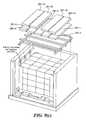
- FIG. 1is an exploded perspective view of one embodiment of an insulated pallet shipper constructed according to the teachings of the present invention, the insulated pallet shipper being shown with a payload;
- FIG. 2is a perspective view of the insulated pallet shipper of FIG. 1 in an assembled state, with the exterior corner braces not being shown;
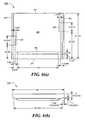
- FIGS. 3( a ) through 3 ( d )are top, section, enlarged section, and perspective views, respectively, of the bottom wall shown in FIG. 1 ;
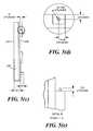
- FIGS. 5( a ) through 5 ( e )are side, top, front, enlarged top, and enlarged front views, respectively, of the left side wall shown in FIG. 1 ;
- FIGS. 6( a ) through 6 ( c )are front, top and side views, respectively, of the rear wall shown in FIG. 1 ;
- FIGS. 8( a ) and 8 ( b )are plan and enlarged views, respectively, of the sheet used in the refrigerant sleeve shown in FIG. 1 ;
- FIG. 8( c )is a plan view, broken away in part, of one of the coolant members shown in FIG. 1 ;
- FIGS. 9( a ) through 9 ( d )are various views illustrating the manner in which the insulated pallet shipper of FIG. 1 may be used.
- FIGS. 1 and 2there are shown exploded perspective and perspective views, respectively, of one embodiment of an insulated pallet shipper constructed according to the teachings of the present invention, said insulated pallet shipper being represented generally by reference numeral 200 .
- a payload 201is shown together with shipper 200 in FIG. 1 .
- Shipper 200may include a top wall 202 , a bottom wall 203 , a left side wall 204 , a right side wall 205 , a rear wall 206 and a front wall 207 .
- Top wall 202 and bottom wall 203may be identical to one another in size, shape and construction
- left side wall 204 and right side wall 205may be identical to one another in size, shape and construction
- rear wall 206 and front wall 207may be identical to one another in size, shape and construction.
- Bottom wall 203which is shown separately in FIGS. 3( a ) through 3 ( d ), may be a generally rectangularly-shaped structure shaped to include a flat bottom 208 , a top 209 , a flat front 211 , a flat rear 213 , a flat left side 215 and a flat right side 217 .
- Top 209may be shaped to include an upwardly-extending peripheral lip 219 and a plurality of upwardly-extending blocks 221 , 223 - 1 and 223 - 2 .
- Lip 219 and blocks 221 , 223 - 1 and 223 - 2 togethermay define a continuous interior groove 225 , groove 225 being adapted to snugly receive the bottom ends of left side wall 204 , right side wall 205 , rear wall 206 , and front wall 207 , respectively.
- Block 221may be effectively bisected along its top surface into a left portion 227 - 1 and a right portion 227 - 2 by a plurality of upwardly-extending projections 228 .
- left portion 227 - 1may be dimensioned so that two coolant members, each oriented parallel to block 223 - 1 , may be securely received between projections 228 and block 223 - 1
- right portion 227 - 2may be dimensioned so that an additional two coolant members, each oriented parallel to block 223 - 2 , may be securely received between projections 228 and block 223 - 2
- blocks 223 - 1 and 223 - 2 and projections 228may be sufficiently great in height so that a shipping pallet may be supported thereon while clearing the coolant members positioned in left portion 227 - 1 and right portion 227 - 2 .
- bottom wall 203may be made in a manner generally similar to that used to make insert 31 of U.S. Pat. No. 6,868,982 and, therefore, may comprise a body of insulating material and a thin, flexible, non-self-supporting, polymer bag.
- the insulating materialmay comprise a body of foamed polymer material, preferably a foamed polyurethane.
- Blowing agentsmay be used to form said foamed polyurethane, such blowing agents including, for example, hydrofluorocarbons (HFC), such as HFC-134a or HFC-245, as well as carbon dioxide, methyl formate, cyclopentanes, and hydrochlorofluorocarbons (HCFC).
- the unfoamed polymer bagmay be made, of hexene or a polyethylene, preferably a high density polyethylene, and may be integrally bonded and conformal to the foamed body, with the bag covering much of the outer surface of the foamed body, excluding the bottom surface of the body.
- bottom wall 203may be formed by replacing the aforementioned unfoamed polymer bag with a combination of one or more sheets of corrugated cardboard material and a plurality of pre-fabricated thermoformed pieces. More specifically, the corrugated cardboard material may be provided with a plurality of transverse openings or cut-outs (see FIG.
- thermoformed pieces4 for a cardboard sheet 229 having openings 230 - 1 , 230 - 2 and 230 - 3 ), with the pre-fabricated thermoformed pieces fixedly mounted in the cut-outs and shaped to define blocks 223 - 1 and 223 - 2 and projections 228 .
- the cardboard material and thermoformed piecesmay be introduced into the mold used to form the foamed body so that the foamed body fills the inwardly-facing cavities of the thermoformed pieces, as well as defining the remainder of the foamed body.
- An additional sheet of corrugated cardboard material or the likemay be used to cover the exposed bottom surface of the foamed body, the sheets of corrugated cardboard material being taped or otherwise fixedly secured to one another.
- Left side wall 204which is shown separately in FIGS. 5( a ) through 5 ( e ), may be a generally rectangularly-shaped member that may include a flat bottom 231 , a flat top 233 , a front 235 , a flat rear 237 , a left side 239 and a right side 241 .
- Bottom 231may be appropriately shaped to fit securely within a corresponding portion of groove 225 of bottom wall 203 .
- Front 235may be shaped to securely receive a plurality of coolant members.
- front 235may include a horizontally-extending projection 243 and two sets of vertically-extending projections 244 - 1 through 244 - 3 and 245 - 1 through 245 - 3 .
- Projection 243may be appropriately dimensioned so that a plurality of coolant members may rest thereupon, with projections 244 - 1 through 244 - 3 and 245 - 1 through 245 - 3 being arranged to separate adjacent coolant members.
- the spacing between adjacent projections 244 - 1 through 244 - 3 and between adjacent projections 245 - 1 through 245 - 3is such that the coolant members securely fit within such spaces, with any air spaces between adjacent projections 244 - 1 through 244 - 3 and between adjacent projections 245 - 1 through 245 - 3 being minimized.
- projections 244 - 1 through 244 - 3 and 245 - 1 through 245 - 1are preferably dimensioned so that their respective heights are less than that of the coolant members, i.e., the coolant members extend more deeply into the cavity of the container than do projections 244 - 1 through 244 - 3 and 245 - 1 through 245 - 3 .
- a pin 247 - 1is fixedly mounted in projection 244 - 1 and extends upwardly a short distance therefrom, and a pin 247 - 2 is fixedly mounted in projection 244 - 3 and extends upwardly a short distance therefrom. As will be seen below, pins 247 - 1 and 247 - 2 are used to mount a coolant tray.
- Left side wall 204may comprise a body of foamed polymer material covered with a corrugated cardboard material or the like. Also, in a fashion similar to that in bottom wall 203 , projections 243 , projections 244 - 1 through 244 - 3 , and projections 245 - 1 through 245 - 3 may be formed using pre-fabricated thermoformed pieces mounted within cut-outs provided in the corrugated cardboard material.
- Rear wall 206which is shown separately in FIGS. 6( a ) through 6 ( c ), may be a generally rectangularly-shaped member that may include a flat bottom 251 , a flat top 253 , a front 255 , a flat rear 257 , a left side 259 and a right side 261 .
- Bottom 251may be appropriately shaped to fit securely within a corresponding portion of groove 225 of bottom wall 203 .
- Front 255may be shaped to include a lower horizontal projection 263 , a left vertical projection 267 , and a right vertical projection 269 .
- Projection 263may be appropriately positioned and dimensioned to serve as a stop to delimit the insertion of a pallet into the interior of the container cavity.
- Left vertical projection 267may be positioned and dimensioned to act in conjunction with projections 244 - 3 and 245 - 3 of left side wall 204 to securely retain a coolant member therebetween.
- right vertical projection 269may be positioned and dimensioned to act in conjunction with projections 244 - 1 and 245 - 1 of right side wall 205 to securely retain a coolant member therebetween.
- Rear wall 206may comprise a body of foamed polymer material covered with a corrugated cardboard material or the like. Also, in a fashion similar to that in bottom wall 203 , projections 263 , 267 and 269 may be formed using pre-fabricated thermoformed pieces mounted within cut-outs provided in the corrugated cardboard material.
- each of left side wall 204 , right side wall 205 , rear wall 206 and front wall 207may be stepped so that the walls fit together in a complementary fashion when the walls are inserted into groove 225 .
- a strip of foam or like weatherstripping materialmay be applied to steps 250 - 1 and 250 - 2 of left side wall 204 (as well as to the corresponding steps of right side wall 205 ) to act as a seal between the mating wall pieces.
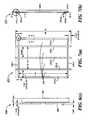
- Shipper 200may further comprise a coolant rack 271 , which is shown separately in FIGS. 7( a ) through 7 ( h ).
- Rack 271may comprise a pair of bars 272 - 1 and 272 - 2 spaced apart from and oriented parallel to one another.
- Bars 272 - 1 and 272 - 2may be made of a strong, rigid polymer or metal and may be hollow and generally rectangular in transverse cross-section.
- a first L-shaped bracket 273 - 1which may be made of a strong, rigid polymer or metal, may be attached at one end by a connecting strip 274 - 1 to the front end of bar 272 - 1 and may be attached at the opposite end by a connecting strip 274 - 2 to the front end of bar 272 - 2 .
- a second L-shaped bracket 273 - 2which may be made of a strong, rigid polymer or metal, may be attached at one end by a connecting strip 274 - 3 to the rear end of bar 272 - 1 and may be attached at the opposite end by a connecting strip 274 - 4 to the rear end of bar 272 - 2 . As can be seen best in FIG.
- brackets 273 - 1 and 273 - 2are oriented to face one another so that the ends of a coolant member may be seated on brackets 273 - 1 and 273 - 2 and extend therebetween.
- Rack 271may further comprise a plurality of crossbars 275 - 1 through 275 - 3 .
- Crossbars 275 - 1 through 275 - 3which may be made of a strong, rigid polymer or metal, may be hollow and generally rectangular in transverse cross-section.
- Crossbars 275 - 1 through 275 - 3may be spaced apart from and oriented parallel to one another, with each of crossbars 275 - 1 through 275 - 3 being seated on top of and oriented generally perpendicularly to bars 272 - 1 and 272 - 2 .
- Each of cross-bars 275 - 1 through 275 - 3may be fixed at a point spaced inwardly from one end to bar 272 - 1 and may be fixed at a point spaced inwardly from the opposite end to bar 272 - 2 .
- Cross-bar 275 - 1may be provided with openings 276 - 1 and 276 - 2 on its bottom surface adapted to receive pins 247 - 1 and 247 - 2 on left side wall 204 and right side wall 205 , respectively, and cross-bar 275 - 3 may be provided with openings 277 - 1 and 277 - 2 on its bottom surface adapted to receive pins 247 - 2 and 247 - 1 on left side wall 204 and right side wall 205 , respectively.
- rack 271may be seated upon projections 244 - 1 through 244 - 3 of left side wall 204 and right side wall 205 .
- a plurality of openings 278are provided between adjacent cross-bars 275 - 1 through 275 - 3 , between bracket 273 - 1 and cross-bar 275 - 1 , and between bracket 273 - 2 and cross-bar 275 - 3 , openings 278 permitting the passage of air cooled by coolant members seated upon rack 271 to the payload spaced below rack 271 .
- Shipper 200may also comprise a plurality of coolant members 281 - 1 through 281 - 21 .
- Coolant members 281 - 1 through 281 - 21may be identical to one another in size, shape and composition, with the only difference amongst coolant members 281 - 1 though 281 - 20 being that certain coolant members, such as coolant members 281 - 1 through 281 - 13 , are preconditioned, preferably for at least 24 hours, at a refrigerating temperature, such as 5° C. ⁇ 3° C., and other coolant members, such as coolant members 281 - 14 through 281 - 21 , are preconditioned, preferably for at least 24 hours, at a freezing temperature, such as ⁇ 20° C. ⁇ 3° C.
- Each coolant member 281may comprise a plurality of (e.g., nine) identical coolant bricks, which bricks may be stacked within a closed-ended sleeve.
- a sleeve 285 for a coolant member 281is shown.
- Sleeve 285may be made of a corrugated cardboard or similar material.
- FIG. 8( c )shows a representative coolant member 281 comprising a plurality of identical coolant bricks 286 - 1 through 286 - 9 stacked within sleeve 285 .
- the coolant bricksmay comprise a foam refrigerant block of hexahedron shape (e.g., 9′′ ⁇ 4′′ ⁇ 1.5′′) encased in a flexible metal foil.
- FIG. 8( d )shows a representative coolant brick 286 comprising a foam refrigerant block 287 encased within a flexible metal foil 288 .
- Shipper 200may further comprise an inner pallet 291 , upon which payload 201 may be seated.
- Pallet 291which may be 48′′ ⁇ 40′′ in size, is adapted to be removably inserted into the cavity of the container, for example, through the open front end of shipper 200 .
- Inner pallet 291may be supplied by the user of shipper 200 .
- Shipper 200may further comprise a plurality of payload corner support braces 301 - 1 through 301 - 4 and a plurality of exterior corner support braces 303 - 1 through 303 - 4 .
- Payload corner support braces 301 - 1 through 301 - 4which may be made of foamboard or the like, may be used to brace the payload, which may be shrink-wrapped together with inner pallet 291 .
- Exterior corner support braces 303 - 1 through 303 - 4may be used to provide support to the exterior corners of the container, which may be secured with straps or the like.
- Shipper 200may further comprise an outer pallet 311 .
- Pallet 311which may be made of a polymer, wood, or another suitable material, is appropriately dimensioned so that the container and its contents may be seated thereupon.
- shipper 200may be varied in size to suit particular applications, illustrative dimensions for a preferred embodiment are shown in several of the drawings.
- Shipper 200may be reversibly assembled and disassembled a number of times. For example, shipper 200 may be stored or transported in an unassembled state and thereafter assembled for use. Following use, shipper 200 may be disassembled and thereafter stored or transported.
- FIGS. 9( a ) through 9 ( d )there is shown one manner in which shipper 200 may be assembled and used.
- left side wall 204 and right side wall 205may be inserted into groove 225 of bottom wall 203
- rear wall 206may be inserted into groove 225 , with rear wall 206 mating with left side wall 204 and right side wall 205 .
- refrigerated coolant members 281 - 12 and 281 - 13may be placed on left portion 227 - 1 of bottom wall 203
- refrigerated coolant members 281 - 10 and 281 - 11may be placed on right portion 227 - 2 of bottom wall 203 .
- refrigerated coolant members 281 - 7 and 281 - 6 and frozen coolant member 281 - 18may be secured to left side wall 204
- refrigerated coolant members 281 - 9 and 281 - 8 and frozen coolant member 281 - 20may be secured to right side wall 205 (see FIG. 9( a )).
- inner pallet 291together with payload 201 seated thereon, may be inserted through the open front end of the container and placed on bottom wall 203 (see FIG. 9( b )).
- the payload seated on inner pallet 291should be centered on pallet 291 and that the payload should not have a footprint that exceeds that of pallet 291 (to avoid contact with rear wall 206 or front wall 207 ). Consequently, the maximum payload is 48′′ L ⁇ 40′′ W ⁇ 38.25′′ H.
- the payloadshould be braced with braces 301 - 1 through 301 - 4 . (Braces 301 - 1 through 301 - 4 should be at the height of the payload and should be cut if necessary).
- the palletshould then be shrink wrapped. Placement markings may be provided on bottom wall 206 to facilitate proper placement of pallet 291 therewithin.
- coolant rack 271may be mounted on pins 247 - 1 and 247 - 2 of left side 204 and of right side 205 .
- coolant members 281 - 1 through 281 - 5may be placed on coolant rack 111
- coolant members 281 - 14 through 281 - 17may be placed on coolant members 281 - 1 through 121 - 5 (see FIG. 9( c )).
- frozen coolant member 281 - 19may be placed against left side wall 204
- frozen coolant member 281 - 21may be placed against right side wall 205 .
- front wall 207may be inserted into sleeve 225 of bottom wall 203 , with front wall 207 mating with left side wall 204 and right side wall 205 , and top wall 202 may be coupled to left side wall 204 , right side wall 205 , rear wall 206 , and front wall 207 (see FIG. 9( d )).
- Braces 303 - 1 through 303 - 4may then be placed on the exterior corners of the container and plastic straps may be wrapped around the container and the outer pallet.
- Shipper 200has been tested under both simulated ambient summer conditions and ambient winter conditions and has been successful in maintaining a full payload and a half payload within a temperature range of +2° C. to +8° C. for a minimum of 120 hours.
Landscapes
- Engineering & Computer Science (AREA)
- Mechanical Engineering (AREA)
- Chemical & Material Sciences (AREA)
- Combustion & Propulsion (AREA)
- Physics & Mathematics (AREA)
- Thermal Sciences (AREA)
- General Engineering & Computer Science (AREA)
- Packages (AREA)
Abstract
Description
Claims (19)
Priority Applications (1)
| Application Number | Priority Date | Filing Date | Title |
|---|---|---|---|
| US12/733,634US9180998B2 (en) | 2007-09-11 | 2008-09-11 | Insulated pallet shipper and methods of making and using the same |
Applications Claiming Priority (4)
| Application Number | Priority Date | Filing Date | Title |
|---|---|---|---|
| US99341907P | 2007-09-11 | 2007-09-11 | |
| US18856508P | 2008-08-11 | 2008-08-11 | |
| PCT/US2008/010660WO2009035661A1 (en) | 2007-09-11 | 2008-09-11 | Insulated pallet shipper and methods of making and using the same |
| US12/733,634US9180998B2 (en) | 2007-09-11 | 2008-09-11 | Insulated pallet shipper and methods of making and using the same |
Publications (2)
| Publication Number | Publication Date |
|---|---|
| US20110049164A1 US20110049164A1 (en) | 2011-03-03 |
| US9180998B2true US9180998B2 (en) | 2015-11-10 |
Family
ID=40452350
Family Applications (1)
| Application Number | Title | Priority Date | Filing Date |
|---|---|---|---|
| US12/733,634Active2032-01-23US9180998B2 (en) | 2007-09-11 | 2008-09-11 | Insulated pallet shipper and methods of making and using the same |
Country Status (4)
| Country | Link |
|---|---|
| US (1) | US9180998B2 (en) |
| EP (1) | EP2200904B1 (en) |
| CA (1) | CA2699413C (en) |
| WO (1) | WO2009035661A1 (en) |
Cited By (25)
| Publication number | Priority date | Publication date | Assignee | Title |
|---|---|---|---|---|
| US20180099778A1 (en)* | 2016-10-06 | 2018-04-12 | Viking Cold Solutions, Inc. | Thermal energy storage pallet |
| US20180327165A1 (en)* | 2017-05-11 | 2018-11-15 | United States Postal Service | Systems and methods for maintaining temperature control of items in a distribution network |
| US20200002075A1 (en)* | 2018-06-15 | 2020-01-02 | Cold Chain Technologies, Inc. | Shipping system for storing and/or transporting temperature-sensitive materials |
| US10661969B2 (en) | 2015-10-06 | 2020-05-26 | Cold Chain Technologies, Llc | Thermally insulated shipping system for pallet-sized payload, methods of making and using the same, and kit for use therein |
| WO2021046491A1 (en) | 2019-09-05 | 2021-03-11 | Cold Chain Technologies, Llc | Shipping system for temperature-sensitive materials |
| US11137190B2 (en) | 2019-06-28 | 2021-10-05 | Cold Chain Technologies, Llc | Method and system for maintaining temperature-sensitive materials within a desired temperature range for a period of time |
| US20220081200A1 (en)* | 2020-09-11 | 2022-03-17 | Sonoco Development, Inc. | Passive Temperature Controlled Packaging System as a ULD |
| US11340005B2 (en) | 2016-07-25 | 2022-05-24 | Cold Chain Technologies, Llc | Hybrid method and system for transporting and/or storing temperature-sensitive materials |
| WO2022114141A1 (en) | 2020-11-27 | 2022-06-02 | 株式会社カネカ | Constant-temperature transport container and thermal-storage medium package linker |
| US11352191B2 (en)* | 2019-09-12 | 2022-06-07 | Buhl-Paperform Gmbh | Packaging for an article and method of packaging an article |
| WO2022178276A1 (en) | 2021-02-19 | 2022-08-25 | Cold Chain Technologies, Llc | Method and system for storing and/or transporting temperature-sensitive materials |
| US11472625B2 (en) | 2019-07-23 | 2022-10-18 | Cold Chain Technologies, Llc | Method and system for maintaining temperature-sensitive materials within a desired temperature range for a period of time |
| WO2022226223A1 (en) | 2021-04-21 | 2022-10-27 | Cold Chain Technologies, Llc | Method and system for storing and/or transporting temperature-sensitive materials |
| US11499770B2 (en) | 2017-05-09 | 2022-11-15 | Cold Chain Technologies, Llc | Shipping system for storing and/or transporting temperature-sensitive materials |
| US11511928B2 (en) | 2017-05-09 | 2022-11-29 | Cold Chain Technologies, Llc | Shipping system for storing and/or transporting temperature-sensitive materials |
| US11591133B2 (en) | 2015-10-06 | 2023-02-28 | Cold Chain Technologies, Llc | Pallet cover comprising one or more temperature-control members and kit for use in making the pallet cover |
| US11634266B2 (en) | 2019-01-17 | 2023-04-25 | Cold Chain Technologies, Llc | Thermally insulated shipping system for parcel-sized payload |
| US11634263B2 (en) | 2015-10-06 | 2023-04-25 | Cold Chain Technologies, Llc | Pallet cover comprising one or more temperature-control members and kit for use in making the pallet cover |
| US11634267B2 (en) | 2015-10-06 | 2023-04-25 | Cold Chain Technologies, Llc | Pallet cover comprising one or more temperature-control members and kit for use in making the pallet cover |
| US11964795B2 (en) | 2015-10-06 | 2024-04-23 | Cold Chain Technologies, Llc | Device comprising one or more temperature-control members and kit for use in making the device |
| US12091233B2 (en) | 2020-03-25 | 2024-09-17 | Cold Chain Technologies, Llc | Product box suitable for receiving temperature-sensitive materials and shipping system including the same |
| US12202665B2 (en) | 2021-07-15 | 2025-01-21 | Pelican Biothermal, Llc | Phase change material panel and passive thermally controlled shipping container employing the panels |
| US12366400B2 (en) | 2021-03-04 | 2025-07-22 | Cold Chain Technologies, Llc | Shipping system for storing and/or transporting temperature-sensitive materials |
| US12378057B2 (en) | 2020-07-02 | 2025-08-05 | Cold Chain Technologies, Llc | Shipping system for storing and/or transporting temperature-sensitive materials |
| US12441532B2 (en) | 2020-11-27 | 2025-10-14 | Kaneka Corporation | Constant-temperature transport container and thermal-storage medium package linker |
Families Citing this family (21)
| Publication number | Priority date | Publication date | Assignee | Title |
|---|---|---|---|---|
| US20110248038A1 (en)* | 2010-04-09 | 2011-10-13 | Minnesota Thermal Science, Llc | Passive thermally controlled bulk shipping container |
| FR2974353B1 (en)* | 2011-04-19 | 2014-06-13 | Emball Iso | ISOTHERMAL CONDITIONING DEVICE FOR THERMOSENSITIVE PRODUCTS |
| BR112013025203A2 (en) | 2011-04-22 | 2016-11-29 | Danisco Us Inc | "Variant strains of filamentous bottoms having genetic modification for increased seb1 protein production and altered growth and their production method." |
| EP2795210B1 (en)* | 2011-12-20 | 2021-03-31 | B Medical Systems S.à.r.l. | Cooling element and cooling device |
| FR2994423B1 (en)* | 2012-08-07 | 2015-12-11 | Sofrigam | THERMAL DEVICE FOR TRANSPORTING PRODUCTS, IN PARTICULAR PALETTIATED PRODUCTS. |
| DE102012022398B4 (en)* | 2012-11-16 | 2019-03-21 | delta T Gesellschaft für Medizintechnik mbH | Modular insulated container |
| GB2538892B (en)* | 2012-11-30 | 2017-05-31 | Laminar Medica Ltd | A thermally insulated shipping container |
| WO2014125878A1 (en)* | 2013-02-13 | 2014-08-21 | 株式会社カネカ | Constant temperature storage/transport container, and transport method |
| CA2850832A1 (en) | 2013-04-30 | 2014-10-30 | Kyle L. Baltz | Pallet and wrap therefor |
| US9272811B1 (en)* | 2014-09-12 | 2016-03-01 | Sonoco Development, Inc. | Temperature controlled pallet shipper |
| US9938066B2 (en) | 2014-09-12 | 2018-04-10 | Sonoco Development, Inc. | Temperature controlled pallet shipper |
| GB2530077A (en)* | 2014-09-12 | 2016-03-16 | Peli Biothermal Ltd | Thermally insulated containers |
| US10011418B2 (en) | 2014-09-26 | 2018-07-03 | Pelican Biothermal Llc | High efficiency bolt-on thermal insulating panel and thermally insulated shipping container employing such a thermal insulating panel |
| GB2535149B (en)* | 2015-02-05 | 2021-09-08 | Laminar Medica Ltd | A thermally insulated container |
| ES2552565B1 (en)* | 2015-07-03 | 2016-09-08 | Fundación Para El Fomento De La Innovación Industrial | Temperature maintenance device in a thermal insulation vessel |
| US9963287B2 (en) | 2015-09-08 | 2018-05-08 | Ekopak, Inc. | Insulated shipping system |
| CN107140283B (en)* | 2017-06-13 | 2019-03-05 | 苏州工业园区维特力彩印包装有限公司 | A kind of novel high-strength packing box |
| FR3090599B1 (en)* | 2018-12-20 | 2021-01-15 | Cold & Co | Improved refrigerant container |
| JP7376923B2 (en)* | 2020-04-28 | 2023-11-09 | トーホー工業株式会社 | medical transport container |
| US20210403224A1 (en)* | 2020-06-24 | 2021-12-30 | World Courier Management Limited | Packaging system for transporting temperature-sensitive products |
| JPWO2023053646A1 (en)* | 2021-09-28 | 2023-04-06 |
Citations (62)
| Publication number | Priority date | Publication date | Assignee | Title |
|---|---|---|---|---|
| US1865688A (en)* | 1931-03-30 | 1932-07-05 | Frederick C Hannaford | Package container |
| US2087966A (en) | 1935-11-27 | 1937-07-27 | Charles E Hadsell | Heat insulated container |
| US2317005A (en) | 1941-04-14 | 1943-04-20 | Wasserman Nathan | Shipping carton |
| US2325371A (en) | 1941-08-23 | 1943-07-27 | Leonard F Clerc | Refrigerated shipping container |
| US2467268A (en)* | 1943-12-08 | 1949-04-12 | Sherman Paper Products Corp | Shipping package using dry ice |
| US2631439A (en)* | 1950-01-28 | 1953-03-17 | Little America Frozen Foods In | Refrigerating shipping container for frozen foods |
| US2728200A (en)* | 1953-05-01 | 1955-12-27 | Lobl Frederick | Refrigerated shipping containers |
| US2915235A (en) | 1956-10-29 | 1959-12-01 | Swift & Co | Container for frozen foods |
| US2989856A (en)* | 1957-04-08 | 1961-06-27 | Telkes Maria | Temperature stabilized container and materials therefor |
| US3205033A (en) | 1961-11-21 | 1965-09-07 | United Service Equipment Co In | Tray support and thermal wall for a hot and cold food service cart |
| GB1061791A (en) | 1963-02-28 | 1967-03-15 | Willard Langdon Morrison | Insulated shipping container |
| US3651974A (en) | 1969-07-07 | 1972-03-28 | Daniel J Barry | Container |
| AU4085772A (en) | 1972-04-06 | 1973-10-11 | Gen Box Co | Insulated shipping container |
| US4090659A (en) | 1976-06-15 | 1978-05-23 | Etablissements Larousse | Insulated container for the storage and transportation of merchandise |
| US4294079A (en) | 1980-03-12 | 1981-10-13 | Better Agricultural Goals Corporation | Insulated container and process for shipping perishables |
| US4377075A (en) | 1981-03-09 | 1983-03-22 | New England Nuclear Corporation | Refrigerant and method for shipping perishable materials |
| US4741167A (en) | 1986-11-20 | 1988-05-03 | Wigley Freddie J | Method and apparatus for transporting perishable materials |
| US4887731A (en) | 1987-12-08 | 1989-12-19 | Bonar Plastics Ltd. | Shipping container |
| US4947658A (en) | 1989-08-22 | 1990-08-14 | Neorx Corporation | Shipping container |
| US5507405A (en) | 1993-12-16 | 1996-04-16 | Great Dane Trailers, Inc. | Thermally insulated cargo container |
| US5669233A (en) | 1996-03-11 | 1997-09-23 | Tcp Reliable Inc. | Collapsible and reusable shipping container |
| US5791150A (en) | 1994-02-18 | 1998-08-11 | Transphere Systems Limited | Pallet based refrigerated transportation system |
| FR2759676A1 (en) | 1997-02-14 | 1998-08-21 | Sofrigam | Isothermic container, e.g. for transporting organs or biological tissues |
| US5809906A (en)* | 1996-08-15 | 1998-09-22 | Chrysler Corporation | Stringerless pallet having adjustable deckboards |
| WO1998043028A1 (en) | 1997-03-27 | 1998-10-01 | Foremost In Packaging Systems, Inc. | Improved insulated shipping container |
| US5881908A (en) | 1997-03-17 | 1999-03-16 | Premier Industries, Inc. | Insulated shipping container for fish |
| US5897017A (en) | 1996-04-16 | 1999-04-27 | Lantz; Gary W. | Insulated shipping container |
| US5899088A (en)* | 1998-05-14 | 1999-05-04 | Throwleigh Technologies, L.L.C. | Phase change system for temperature control |
| US5950450A (en) | 1996-06-12 | 1999-09-14 | Vacupanel, Inc. | Containment system for transporting and storing temperature-sensitive materials |
| US5953928A (en) | 1997-05-13 | 1999-09-21 | Saia, Iii; Louis P. | Portable self-contained cooler/freezer apparatus for use on airplanes, common carrier type unrefrigerated truck lines, and vessels |
| US5983661A (en) | 1997-11-28 | 1999-11-16 | Wiesman; Jon P. | Container arrangement and method for transporting equine semen |
| US5987910A (en) | 1996-12-02 | 1999-11-23 | Waggonbau Elze Gmbh & Co. Besitz Kg | Large-volume insulated shipping container |
| US6016664A (en) | 1996-01-23 | 2000-01-25 | Frigotainer Insulated Air Cargo Containers Ab | Freezing container arrangement |
| US6266972B1 (en) | 1998-12-07 | 2001-07-31 | Vesture Corporation | Modular freezer pallet and method for storing perishable items |
| US6325281B1 (en) | 2000-03-30 | 2001-12-04 | Polyfoam Packers Corporation | Thermally insulating shipping system |
| US20030012701A1 (en) | 2001-07-13 | 2003-01-16 | Sangha Jangbir S. | Insulated specimen sampling and shipping kit |
| JP2003096442A (en)* | 2001-09-26 | 2003-04-03 | Takatsugu Oizumi | Cold insulating panel given by mixing polystyrene with sodium bicarbonate and water |
| US6558608B2 (en) | 1995-06-28 | 2003-05-06 | Tpi Technology, Inc. | Method for molding fiber reinforced composite container |
| US6584797B1 (en) | 2001-06-06 | 2003-07-01 | Nanopore, Inc. | Temperature-controlled shipping container and method for using same |
| US20030217948A1 (en) | 2002-05-22 | 2003-11-27 | Lantz Gary W. | Shock absorbing insulated shipping container especially for breakable glass bottles |
| US6666032B1 (en) | 1999-07-01 | 2003-12-23 | Kryotrans Limited | Thermally insulated container |
| US6832562B2 (en) | 2001-02-20 | 2004-12-21 | Packaging Specialties, Inc. | Shipping container |
| US6868982B2 (en) | 2001-12-05 | 2005-03-22 | Cold Chain Technologies, Inc. | Insulated shipping container and method of making the same |
| US7028504B2 (en) | 2003-07-07 | 2006-04-18 | Rodney Derifield | Insulated shipping containers |
| WO2006082433A1 (en) | 2005-02-03 | 2006-08-10 | Tattam Edwin F | Transport container |
| US20070051734A1 (en) | 2003-05-19 | 2007-03-08 | Va-Q-Tec Ag | Thermally insulated container |
| US7257963B2 (en) | 2003-05-19 | 2007-08-21 | Minnesota Thermal Science, Llc | Thermal insert for container having a passive controlled temperature interior |
| US7310967B2 (en) | 2004-02-20 | 2007-12-25 | Aragon Daniel M | Temperature controlled container |
| US7328583B2 (en) | 2004-01-12 | 2008-02-12 | Entropy Solutions, Inc. | Thermally stable containment device and methods |
| US20080276643A1 (en)* | 2005-09-12 | 2008-11-13 | Adam Heroux | Thermally Insulated Transport Container For Cell-Based Products and Related Methods |
| US7631799B2 (en) | 2004-04-13 | 2009-12-15 | S.C. Johnson Home Storage, Inc. | Container and blank for making the same |
| US7721566B1 (en) | 2006-08-14 | 2010-05-25 | Minnesota Thermal Science, Llc | Collapsible interconnected panels of phase change material |
| US20100301057A1 (en) | 2009-05-29 | 2010-12-02 | Softbox Systems Limited | Transport Container |
| US7913511B2 (en) | 2005-06-08 | 2011-03-29 | Doubleday Acquisitions, Llc | Cargo container for transporting temperature sensitive items |
| US20130015191A1 (en) | 2011-07-15 | 2013-01-17 | Airdex International, Inc. | Climate control cargo container for storing,transporting and preserving cargo |
| US20130255306A1 (en) | 2012-03-27 | 2013-10-03 | William T. Mayer | Passive thermally regulated shipping container employing phase change material panels containing dual immiscible phase change materials |
| FR2989359A1 (en) | 2012-04-12 | 2013-10-18 | Kalibox | Removable isothermal container for containing e.g. drugs, has assembling unit including sections comprising U-shaped part, each being associated with one of base, rear bottom and side panels, where U-shaped part receives edge of base panel |
| US8607581B2 (en) | 2007-05-04 | 2013-12-17 | Entropy Solutions, Inc. | Package having phase change materials and method of use in transport of temperature sensitive payload |
| US8672137B2 (en) | 2006-02-09 | 2014-03-18 | Airdex International, Inc. | Modular, knock down, light weight, thermally insulating, tamper proof cargo container |
| WO2014083320A1 (en) | 2012-11-30 | 2014-06-05 | Laminar Medica Limited | A thermally insulated shipping container |
| US20140174692A1 (en) | 2012-12-23 | 2014-06-26 | Illuminate Consulting, Llc. | Method and apparatus for thermally protecting and/or transporting temperature sensitive products |
| US8763886B2 (en) | 2011-11-09 | 2014-07-01 | Alpine Thermal Technologies, Inc. | Insulating shipping system |
- 2008
- 2008-09-11USUS12/733,634patent/US9180998B2/enactiveActive
- 2008-09-11WOPCT/US2008/010660patent/WO2009035661A1/enactiveApplication Filing
- 2008-09-11CACA2699413Apatent/CA2699413C/ennot_activeExpired - Fee Related
- 2008-09-11EPEP08830672.5Apatent/EP2200904B1/ennot_activeNot-in-force
Patent Citations (66)
| Publication number | Priority date | Publication date | Assignee | Title |
|---|---|---|---|---|
| US1865688A (en)* | 1931-03-30 | 1932-07-05 | Frederick C Hannaford | Package container |
| US2087966A (en) | 1935-11-27 | 1937-07-27 | Charles E Hadsell | Heat insulated container |
| US2317005A (en) | 1941-04-14 | 1943-04-20 | Wasserman Nathan | Shipping carton |
| US2325371A (en) | 1941-08-23 | 1943-07-27 | Leonard F Clerc | Refrigerated shipping container |
| US2467268A (en)* | 1943-12-08 | 1949-04-12 | Sherman Paper Products Corp | Shipping package using dry ice |
| US2631439A (en)* | 1950-01-28 | 1953-03-17 | Little America Frozen Foods In | Refrigerating shipping container for frozen foods |
| US2728200A (en)* | 1953-05-01 | 1955-12-27 | Lobl Frederick | Refrigerated shipping containers |
| US2915235A (en) | 1956-10-29 | 1959-12-01 | Swift & Co | Container for frozen foods |
| US2989856A (en)* | 1957-04-08 | 1961-06-27 | Telkes Maria | Temperature stabilized container and materials therefor |
| US3205033A (en) | 1961-11-21 | 1965-09-07 | United Service Equipment Co In | Tray support and thermal wall for a hot and cold food service cart |
| GB1061791A (en) | 1963-02-28 | 1967-03-15 | Willard Langdon Morrison | Insulated shipping container |
| US3651974A (en) | 1969-07-07 | 1972-03-28 | Daniel J Barry | Container |
| AU4085772A (en) | 1972-04-06 | 1973-10-11 | Gen Box Co | Insulated shipping container |
| US4090659A (en) | 1976-06-15 | 1978-05-23 | Etablissements Larousse | Insulated container for the storage and transportation of merchandise |
| US4294079A (en) | 1980-03-12 | 1981-10-13 | Better Agricultural Goals Corporation | Insulated container and process for shipping perishables |
| US4377075A (en) | 1981-03-09 | 1983-03-22 | New England Nuclear Corporation | Refrigerant and method for shipping perishable materials |
| US4741167A (en) | 1986-11-20 | 1988-05-03 | Wigley Freddie J | Method and apparatus for transporting perishable materials |
| US4887731A (en) | 1987-12-08 | 1989-12-19 | Bonar Plastics Ltd. | Shipping container |
| US4947658A (en) | 1989-08-22 | 1990-08-14 | Neorx Corporation | Shipping container |
| US5507405A (en) | 1993-12-16 | 1996-04-16 | Great Dane Trailers, Inc. | Thermally insulated cargo container |
| US5791150A (en) | 1994-02-18 | 1998-08-11 | Transphere Systems Limited | Pallet based refrigerated transportation system |
| US6558608B2 (en) | 1995-06-28 | 2003-05-06 | Tpi Technology, Inc. | Method for molding fiber reinforced composite container |
| US6016664A (en) | 1996-01-23 | 2000-01-25 | Frigotainer Insulated Air Cargo Containers Ab | Freezing container arrangement |
| US5669233A (en) | 1996-03-11 | 1997-09-23 | Tcp Reliable Inc. | Collapsible and reusable shipping container |
| US6257764B1 (en) | 1996-04-16 | 2001-07-10 | Gary W. Lantz | Insulated shipping container, method of making, and article and machine used in making |
| US5897017A (en) | 1996-04-16 | 1999-04-27 | Lantz; Gary W. | Insulated shipping container |
| US5950450A (en) | 1996-06-12 | 1999-09-14 | Vacupanel, Inc. | Containment system for transporting and storing temperature-sensitive materials |
| US5809906A (en)* | 1996-08-15 | 1998-09-22 | Chrysler Corporation | Stringerless pallet having adjustable deckboards |
| US5987910A (en) | 1996-12-02 | 1999-11-23 | Waggonbau Elze Gmbh & Co. Besitz Kg | Large-volume insulated shipping container |
| FR2759676A1 (en) | 1997-02-14 | 1998-08-21 | Sofrigam | Isothermic container, e.g. for transporting organs or biological tissues |
| US5881908A (en) | 1997-03-17 | 1999-03-16 | Premier Industries, Inc. | Insulated shipping container for fish |
| WO1998043028A1 (en) | 1997-03-27 | 1998-10-01 | Foremost In Packaging Systems, Inc. | Improved insulated shipping container |
| US5924302A (en) | 1997-03-27 | 1999-07-20 | Foremost In Packaging Systems, Inc. | Insulated shipping container |
| US5953928A (en) | 1997-05-13 | 1999-09-21 | Saia, Iii; Louis P. | Portable self-contained cooler/freezer apparatus for use on airplanes, common carrier type unrefrigerated truck lines, and vessels |
| US5983661A (en) | 1997-11-28 | 1999-11-16 | Wiesman; Jon P. | Container arrangement and method for transporting equine semen |
| US5899088A (en)* | 1998-05-14 | 1999-05-04 | Throwleigh Technologies, L.L.C. | Phase change system for temperature control |
| US6266972B1 (en) | 1998-12-07 | 2001-07-31 | Vesture Corporation | Modular freezer pallet and method for storing perishable items |
| US6666032B1 (en) | 1999-07-01 | 2003-12-23 | Kryotrans Limited | Thermally insulated container |
| US6325281B1 (en) | 2000-03-30 | 2001-12-04 | Polyfoam Packers Corporation | Thermally insulating shipping system |
| US6832562B2 (en) | 2001-02-20 | 2004-12-21 | Packaging Specialties, Inc. | Shipping container |
| US6584797B1 (en) | 2001-06-06 | 2003-07-01 | Nanopore, Inc. | Temperature-controlled shipping container and method for using same |
| US20030012701A1 (en) | 2001-07-13 | 2003-01-16 | Sangha Jangbir S. | Insulated specimen sampling and shipping kit |
| JP2003096442A (en)* | 2001-09-26 | 2003-04-03 | Takatsugu Oizumi | Cold insulating panel given by mixing polystyrene with sodium bicarbonate and water |
| US6868982B2 (en) | 2001-12-05 | 2005-03-22 | Cold Chain Technologies, Inc. | Insulated shipping container and method of making the same |
| US20030217948A1 (en) | 2002-05-22 | 2003-11-27 | Lantz Gary W. | Shock absorbing insulated shipping container especially for breakable glass bottles |
| US20070051734A1 (en) | 2003-05-19 | 2007-03-08 | Va-Q-Tec Ag | Thermally insulated container |
| US7257963B2 (en) | 2003-05-19 | 2007-08-21 | Minnesota Thermal Science, Llc | Thermal insert for container having a passive controlled temperature interior |
| US7028504B2 (en) | 2003-07-07 | 2006-04-18 | Rodney Derifield | Insulated shipping containers |
| US7225632B2 (en) | 2003-07-07 | 2007-06-05 | Rodney Derifield | Insulated shipping containers |
| US7328583B2 (en) | 2004-01-12 | 2008-02-12 | Entropy Solutions, Inc. | Thermally stable containment device and methods |
| US7310967B2 (en) | 2004-02-20 | 2007-12-25 | Aragon Daniel M | Temperature controlled container |
| US7631799B2 (en) | 2004-04-13 | 2009-12-15 | S.C. Johnson Home Storage, Inc. | Container and blank for making the same |
| WO2006082433A1 (en) | 2005-02-03 | 2006-08-10 | Tattam Edwin F | Transport container |
| US7913511B2 (en) | 2005-06-08 | 2011-03-29 | Doubleday Acquisitions, Llc | Cargo container for transporting temperature sensitive items |
| US20080276643A1 (en)* | 2005-09-12 | 2008-11-13 | Adam Heroux | Thermally Insulated Transport Container For Cell-Based Products and Related Methods |
| US8672137B2 (en) | 2006-02-09 | 2014-03-18 | Airdex International, Inc. | Modular, knock down, light weight, thermally insulating, tamper proof cargo container |
| US7721566B1 (en) | 2006-08-14 | 2010-05-25 | Minnesota Thermal Science, Llc | Collapsible interconnected panels of phase change material |
| US8607581B2 (en) | 2007-05-04 | 2013-12-17 | Entropy Solutions, Inc. | Package having phase change materials and method of use in transport of temperature sensitive payload |
| US20100301057A1 (en) | 2009-05-29 | 2010-12-02 | Softbox Systems Limited | Transport Container |
| US8763423B2 (en) | 2009-05-29 | 2014-07-01 | Softbox Systems Ltd. | Cargo container temperature control system |
| US20130015191A1 (en) | 2011-07-15 | 2013-01-17 | Airdex International, Inc. | Climate control cargo container for storing,transporting and preserving cargo |
| US8763886B2 (en) | 2011-11-09 | 2014-07-01 | Alpine Thermal Technologies, Inc. | Insulating shipping system |
| US20130255306A1 (en) | 2012-03-27 | 2013-10-03 | William T. Mayer | Passive thermally regulated shipping container employing phase change material panels containing dual immiscible phase change materials |
| FR2989359A1 (en) | 2012-04-12 | 2013-10-18 | Kalibox | Removable isothermal container for containing e.g. drugs, has assembling unit including sections comprising U-shaped part, each being associated with one of base, rear bottom and side panels, where U-shaped part receives edge of base panel |
| WO2014083320A1 (en) | 2012-11-30 | 2014-06-05 | Laminar Medica Limited | A thermally insulated shipping container |
| US20140174692A1 (en) | 2012-12-23 | 2014-06-26 | Illuminate Consulting, Llc. | Method and apparatus for thermally protecting and/or transporting temperature sensitive products |
Non-Patent Citations (2)
| Title |
|---|
| English Translation of JP 2003-096442 to Oizumi, Publication date: Apr. 2003, Translated Apr. 2014.* |
| http://www.merriam-webster.com/dictionary/receive, Merriam-Webster, Date accessed:Jan. 28, 2015.* |
Cited By (35)
| Publication number | Priority date | Publication date | Assignee | Title |
|---|---|---|---|---|
| US11572227B2 (en) | 2015-10-06 | 2023-02-07 | Cold Chain Technologies, Llc | Thermally insulated shipping system for pallet-sized payload, methods of making and using the same, and kit for use therein |
| US11964795B2 (en) | 2015-10-06 | 2024-04-23 | Cold Chain Technologies, Llc | Device comprising one or more temperature-control members and kit for use in making the device |
| US11634267B2 (en) | 2015-10-06 | 2023-04-25 | Cold Chain Technologies, Llc | Pallet cover comprising one or more temperature-control members and kit for use in making the pallet cover |
| US10661969B2 (en) | 2015-10-06 | 2020-05-26 | Cold Chain Technologies, Llc | Thermally insulated shipping system for pallet-sized payload, methods of making and using the same, and kit for use therein |
| US11634263B2 (en) | 2015-10-06 | 2023-04-25 | Cold Chain Technologies, Llc | Pallet cover comprising one or more temperature-control members and kit for use in making the pallet cover |
| US11591133B2 (en) | 2015-10-06 | 2023-02-28 | Cold Chain Technologies, Llc | Pallet cover comprising one or more temperature-control members and kit for use in making the pallet cover |
| US11340005B2 (en) | 2016-07-25 | 2022-05-24 | Cold Chain Technologies, Llc | Hybrid method and system for transporting and/or storing temperature-sensitive materials |
| US20180099778A1 (en)* | 2016-10-06 | 2018-04-12 | Viking Cold Solutions, Inc. | Thermal energy storage pallet |
| US11655069B2 (en) | 2016-10-06 | 2023-05-23 | Viking Cold Solutons Inc. | Pallet with thermal energy storage |
| US10919665B2 (en)* | 2016-10-06 | 2021-02-16 | Viking Cold Solutions, Inc. | Pallet with thermal energy storage |
| US12043470B2 (en) | 2017-05-09 | 2024-07-23 | Cold Chain Technologies, Llc | Shipping system for storing and/or transporting temperature-sensitive materials |
| US11511928B2 (en) | 2017-05-09 | 2022-11-29 | Cold Chain Technologies, Llc | Shipping system for storing and/or transporting temperature-sensitive materials |
| US11499770B2 (en) | 2017-05-09 | 2022-11-15 | Cold Chain Technologies, Llc | Shipping system for storing and/or transporting temperature-sensitive materials |
| US12330854B2 (en) | 2017-05-11 | 2025-06-17 | United States Postal Service | Systems and methods for maintaining temperature control of items in a distribution network |
| US11975907B2 (en)* | 2017-05-11 | 2024-05-07 | United States Postal Service | Systems and methods for maintaining temperature control of items in a distribution network |
| US20180327165A1 (en)* | 2017-05-11 | 2018-11-15 | United States Postal Service | Systems and methods for maintaining temperature control of items in a distribution network |
| US20220281671A1 (en)* | 2018-06-15 | 2022-09-08 | Cold Chain Technologies, Llc | Shipping system for storing and/or transporting temperature-sensitive materials |
| US11608221B2 (en)* | 2018-06-15 | 2023-03-21 | Cold Chain Technologies, Llc | Shipping system for storing and/or transporting temperature-sensitive materials |
| US20200002075A1 (en)* | 2018-06-15 | 2020-01-02 | Cold Chain Technologies, Inc. | Shipping system for storing and/or transporting temperature-sensitive materials |
| US12371242B2 (en)* | 2018-06-15 | 2025-07-29 | Cold Chain Technologies, Llc | Shipping system for storing and/or transporting temperature-sensitive materials |
| US11634266B2 (en) | 2019-01-17 | 2023-04-25 | Cold Chain Technologies, Llc | Thermally insulated shipping system for parcel-sized payload |
| US11137190B2 (en) | 2019-06-28 | 2021-10-05 | Cold Chain Technologies, Llc | Method and system for maintaining temperature-sensitive materials within a desired temperature range for a period of time |
| US11472625B2 (en) | 2019-07-23 | 2022-10-18 | Cold Chain Technologies, Llc | Method and system for maintaining temperature-sensitive materials within a desired temperature range for a period of time |
| WO2021046491A1 (en) | 2019-09-05 | 2021-03-11 | Cold Chain Technologies, Llc | Shipping system for temperature-sensitive materials |
| US11352191B2 (en)* | 2019-09-12 | 2022-06-07 | Buhl-Paperform Gmbh | Packaging for an article and method of packaging an article |
| US12091233B2 (en) | 2020-03-25 | 2024-09-17 | Cold Chain Technologies, Llc | Product box suitable for receiving temperature-sensitive materials and shipping system including the same |
| US12378057B2 (en) | 2020-07-02 | 2025-08-05 | Cold Chain Technologies, Llc | Shipping system for storing and/or transporting temperature-sensitive materials |
| US20220081200A1 (en)* | 2020-09-11 | 2022-03-17 | Sonoco Development, Inc. | Passive Temperature Controlled Packaging System as a ULD |
| WO2022114141A1 (en) | 2020-11-27 | 2022-06-02 | 株式会社カネカ | Constant-temperature transport container and thermal-storage medium package linker |
| US12441532B2 (en) | 2020-11-27 | 2025-10-14 | Kaneka Corporation | Constant-temperature transport container and thermal-storage medium package linker |
| US12077363B2 (en) | 2021-02-19 | 2024-09-03 | Cold Chain Technologies, Llc | Method and system for storing and/or transporting temperature-sensitive materials |
| WO2022178276A1 (en) | 2021-02-19 | 2022-08-25 | Cold Chain Technologies, Llc | Method and system for storing and/or transporting temperature-sensitive materials |
| US12366400B2 (en) | 2021-03-04 | 2025-07-22 | Cold Chain Technologies, Llc | Shipping system for storing and/or transporting temperature-sensitive materials |
| WO2022226223A1 (en) | 2021-04-21 | 2022-10-27 | Cold Chain Technologies, Llc | Method and system for storing and/or transporting temperature-sensitive materials |
| US12202665B2 (en) | 2021-07-15 | 2025-01-21 | Pelican Biothermal, Llc | Phase change material panel and passive thermally controlled shipping container employing the panels |
Also Published As
| Publication number | Publication date |
|---|---|
| CA2699413C (en) | 2013-09-10 |
| EP2200904A1 (en) | 2010-06-30 |
| WO2009035661A1 (en) | 2009-03-19 |
| EP2200904B1 (en) | 2013-06-26 |
| CA2699413A1 (en) | 2009-03-19 |
| EP2200904A4 (en) | 2012-06-27 |
| US20110049164A1 (en) | 2011-03-03 |
Similar Documents
| Publication | Publication Date | Title |
|---|---|---|
| US9180998B2 (en) | Insulated pallet shipper and methods of making and using the same | |
| US11572227B2 (en) | Thermally insulated shipping system for pallet-sized payload, methods of making and using the same, and kit for use therein | |
| US6266972B1 (en) | Modular freezer pallet and method for storing perishable items | |
| US9045278B2 (en) | Insulated shipping container and method of making the same | |
| US12091233B2 (en) | Product box suitable for receiving temperature-sensitive materials and shipping system including the same | |
| AU2004257250B2 (en) | Insulated shipping containers | |
| JP4981889B2 (en) | Container for transporting cooling articles | |
| EP2374443B1 (en) | Passive thermally controlled bulk shipping container | |
| US20070257040A1 (en) | Packaging for perishable goods | |
| US4576017A (en) | Insulated shipping container | |
| US12366400B2 (en) | Shipping system for storing and/or transporting temperature-sensitive materials | |
| US5425521A (en) | Thermal spacer device | |
| JPH039011B2 (en) | ||
| US20230227236A1 (en) | System suitable for storing and/or transporting temperature-sensitive materials | |
| JP2002139193A (en) | Heat insulating structure member and its component wall molding method | |
| WO2002074642A1 (en) | A collapsible insulated freight container | |
| JP2004196410A (en) | How to transport food | |
| KR101982638B1 (en) | Superchilling packaging system for fresh delivery | |
| JP2000327041A (en) | Insulated container | |
| CN208731463U (en) | A modular folding multi-purpose box | |
| WO1995010378A1 (en) | Method and apparatus for insulating pallet sized containers | |
| JPH0555394B2 (en) | ||
| JPH0710179A (en) | Refrigeration case | |
| CA2544284A1 (en) | Packaging for perishable goods | |
| JPH0560329B2 (en) |
Legal Events
| Date | Code | Title | Description |
|---|---|---|---|
| AS | Assignment | Owner name:COLD CHAIN TECHNOLOGIES, INC., MASSACHUSETTS Free format text:ASSIGNMENT OF ASSIGNORS INTEREST;ASSIGNORS:BANKS, MARK;MUSTAFA, NERITAN;GORDON, LAWRENCE A.;AND OTHERS;SIGNING DATES FROM 20100607 TO 20100707;REEL/FRAME:024824/0586 | |
| STCF | Information on status: patent grant | Free format text:PATENTED CASE | |
| AS | Assignment | Owner name:COLD CHAIN TECHNOLOGIES, INC., MASSACHUSETTS Free format text:CHANGE OF ADDRESS OF ASSIGNEE;ASSIGNOR:COLD CHAIN TECHNOLOGIES, INC.;REEL/FRAME:046779/0558 Effective date:20180813 | |
| MAFP | Maintenance fee payment | Free format text:PAYMENT OF MAINTENANCE FEE, 4TH YR, SMALL ENTITY (ORIGINAL EVENT CODE: M2551); ENTITY STATUS OF PATENT OWNER: SMALL ENTITY Year of fee payment:4 | |
| AS | Assignment | Owner name:ANTARES CAPITAL LP, AS AGENT, ILLINOIS Free format text:PATENT SECURITY AGREEMENT;ASSIGNOR:COLD CHAIN TECHNOLOGIES, LLC;REEL/FRAME:049945/0515 Effective date:20190802 | |
| AS | Assignment | Owner name:COLD CHAIN TECHNOLOGIES, LLC, MASSACHUSETTS Free format text:CHANGE OF NAME;ASSIGNOR:COLD CHAIN TECHNOLOGIES, INC.;REEL/FRAME:051642/0744 Effective date:20190730 | |
| FEPP | Fee payment procedure | Free format text:ENTITY STATUS SET TO UNDISCOUNTED (ORIGINAL EVENT CODE: BIG.); ENTITY STATUS OF PATENT OWNER: LARGE ENTITY | |
| MAFP | Maintenance fee payment | Free format text:PAYMENT OF MAINTENANCE FEE, 8TH YEAR, LARGE ENTITY (ORIGINAL EVENT CODE: M1552); ENTITY STATUS OF PATENT OWNER: LARGE ENTITY Year of fee payment:8 |