US9180768B2 - Method for operating a hybrid drive device - Google Patents
Method for operating a hybrid drive deviceDownload PDFInfo
- Publication number
- US9180768B2 US9180768B2US12/810,692US81069208AUS9180768B2US 9180768 B2US9180768 B2US 9180768B2US 81069208 AUS81069208 AUS 81069208AUS 9180768 B2US9180768 B2US 9180768B2
- Authority
- US
- United States
- Prior art keywords
- torque
- combustion engine
- determined
- slip torque
- separating clutch
- Prior art date
- Legal status (The legal status is an assumption and is not a legal conclusion. Google has not performed a legal analysis and makes no representation as to the accuracy of the status listed.)
- Expired - Fee Related, expires
Links
Images


Classifications
- B—PERFORMING OPERATIONS; TRANSPORTING
- B60—VEHICLES IN GENERAL
- B60W—CONJOINT CONTROL OF VEHICLE SUB-UNITS OF DIFFERENT TYPE OR DIFFERENT FUNCTION; CONTROL SYSTEMS SPECIALLY ADAPTED FOR HYBRID VEHICLES; ROAD VEHICLE DRIVE CONTROL SYSTEMS FOR PURPOSES NOT RELATED TO THE CONTROL OF A PARTICULAR SUB-UNIT
- B60W20/00—Control systems specially adapted for hybrid vehicles
- B60W20/40—Controlling the engagement or disengagement of prime movers, e.g. for transition between prime movers
- B—PERFORMING OPERATIONS; TRANSPORTING
- B60—VEHICLES IN GENERAL
- B60K—ARRANGEMENT OR MOUNTING OF PROPULSION UNITS OR OF TRANSMISSIONS IN VEHICLES; ARRANGEMENT OR MOUNTING OF PLURAL DIVERSE PRIME-MOVERS IN VEHICLES; AUXILIARY DRIVES FOR VEHICLES; INSTRUMENTATION OR DASHBOARDS FOR VEHICLES; ARRANGEMENTS IN CONNECTION WITH COOLING, AIR INTAKE, GAS EXHAUST OR FUEL SUPPLY OF PROPULSION UNITS IN VEHICLES
- B60K6/00—Arrangement or mounting of plural diverse prime-movers for mutual or common propulsion, e.g. hybrid propulsion systems comprising electric motors and internal combustion engines
- B60K6/20—Arrangement or mounting of plural diverse prime-movers for mutual or common propulsion, e.g. hybrid propulsion systems comprising electric motors and internal combustion engines the prime-movers consisting of electric motors and internal combustion engines, e.g. HEVs
- B60K6/42—Arrangement or mounting of plural diverse prime-movers for mutual or common propulsion, e.g. hybrid propulsion systems comprising electric motors and internal combustion engines the prime-movers consisting of electric motors and internal combustion engines, e.g. HEVs characterised by the architecture of the hybrid electric vehicle
- B60K6/48—Parallel type
- B—PERFORMING OPERATIONS; TRANSPORTING
- B60—VEHICLES IN GENERAL
- B60W—CONJOINT CONTROL OF VEHICLE SUB-UNITS OF DIFFERENT TYPE OR DIFFERENT FUNCTION; CONTROL SYSTEMS SPECIALLY ADAPTED FOR HYBRID VEHICLES; ROAD VEHICLE DRIVE CONTROL SYSTEMS FOR PURPOSES NOT RELATED TO THE CONTROL OF A PARTICULAR SUB-UNIT
- B60W10/00—Conjoint control of vehicle sub-units of different type or different function
- B60W10/02—Conjoint control of vehicle sub-units of different type or different function including control of driveline clutches
- B—PERFORMING OPERATIONS; TRANSPORTING
- B60—VEHICLES IN GENERAL
- B60W—CONJOINT CONTROL OF VEHICLE SUB-UNITS OF DIFFERENT TYPE OR DIFFERENT FUNCTION; CONTROL SYSTEMS SPECIALLY ADAPTED FOR HYBRID VEHICLES; ROAD VEHICLE DRIVE CONTROL SYSTEMS FOR PURPOSES NOT RELATED TO THE CONTROL OF A PARTICULAR SUB-UNIT
- B60W10/00—Conjoint control of vehicle sub-units of different type or different function
- B60W10/04—Conjoint control of vehicle sub-units of different type or different function including control of propulsion units
- B60W10/08—Conjoint control of vehicle sub-units of different type or different function including control of propulsion units including control of electric propulsion units, e.g. motors or generators
- B—PERFORMING OPERATIONS; TRANSPORTING
- B60—VEHICLES IN GENERAL
- B60W—CONJOINT CONTROL OF VEHICLE SUB-UNITS OF DIFFERENT TYPE OR DIFFERENT FUNCTION; CONTROL SYSTEMS SPECIALLY ADAPTED FOR HYBRID VEHICLES; ROAD VEHICLE DRIVE CONTROL SYSTEMS FOR PURPOSES NOT RELATED TO THE CONTROL OF A PARTICULAR SUB-UNIT
- B60W30/00—Purposes of road vehicle drive control systems not related to the control of a particular sub-unit, e.g. of systems using conjoint control of vehicle sub-units
- B60W30/18—Propelling the vehicle
- B60W30/192—Mitigating problems related to power-up or power-down of the driveline, e.g. start-up of a cold engine
- B—PERFORMING OPERATIONS; TRANSPORTING
- B60—VEHICLES IN GENERAL
- B60L—PROPULSION OF ELECTRICALLY-PROPELLED VEHICLES; SUPPLYING ELECTRIC POWER FOR AUXILIARY EQUIPMENT OF ELECTRICALLY-PROPELLED VEHICLES; ELECTRODYNAMIC BRAKE SYSTEMS FOR VEHICLES IN GENERAL; MAGNETIC SUSPENSION OR LEVITATION FOR VEHICLES; MONITORING OPERATING VARIABLES OF ELECTRICALLY-PROPELLED VEHICLES; ELECTRIC SAFETY DEVICES FOR ELECTRICALLY-PROPELLED VEHICLES
- B60L2240/00—Control parameters of input or output; Target parameters
- B60L2240/40—Drive Train control parameters
- B60L2240/42—Drive Train control parameters related to electric machines
- B60L2240/421—Speed
- B—PERFORMING OPERATIONS; TRANSPORTING
- B60—VEHICLES IN GENERAL
- B60L—PROPULSION OF ELECTRICALLY-PROPELLED VEHICLES; SUPPLYING ELECTRIC POWER FOR AUXILIARY EQUIPMENT OF ELECTRICALLY-PROPELLED VEHICLES; ELECTRODYNAMIC BRAKE SYSTEMS FOR VEHICLES IN GENERAL; MAGNETIC SUSPENSION OR LEVITATION FOR VEHICLES; MONITORING OPERATING VARIABLES OF ELECTRICALLY-PROPELLED VEHICLES; ELECTRIC SAFETY DEVICES FOR ELECTRICALLY-PROPELLED VEHICLES
- B60L2240/00—Control parameters of input or output; Target parameters
- B60L2240/40—Drive Train control parameters
- B60L2240/42—Drive Train control parameters related to electric machines
- B60L2240/423—Torque
- B—PERFORMING OPERATIONS; TRANSPORTING
- B60—VEHICLES IN GENERAL
- B60L—PROPULSION OF ELECTRICALLY-PROPELLED VEHICLES; SUPPLYING ELECTRIC POWER FOR AUXILIARY EQUIPMENT OF ELECTRICALLY-PROPELLED VEHICLES; ELECTRODYNAMIC BRAKE SYSTEMS FOR VEHICLES IN GENERAL; MAGNETIC SUSPENSION OR LEVITATION FOR VEHICLES; MONITORING OPERATING VARIABLES OF ELECTRICALLY-PROPELLED VEHICLES; ELECTRIC SAFETY DEVICES FOR ELECTRICALLY-PROPELLED VEHICLES
- B60L2240/00—Control parameters of input or output; Target parameters
- B60L2240/40—Drive Train control parameters
- B60L2240/44—Drive Train control parameters related to combustion engines
- B60L2240/441—Speed
- B—PERFORMING OPERATIONS; TRANSPORTING
- B60—VEHICLES IN GENERAL
- B60L—PROPULSION OF ELECTRICALLY-PROPELLED VEHICLES; SUPPLYING ELECTRIC POWER FOR AUXILIARY EQUIPMENT OF ELECTRICALLY-PROPELLED VEHICLES; ELECTRODYNAMIC BRAKE SYSTEMS FOR VEHICLES IN GENERAL; MAGNETIC SUSPENSION OR LEVITATION FOR VEHICLES; MONITORING OPERATING VARIABLES OF ELECTRICALLY-PROPELLED VEHICLES; ELECTRIC SAFETY DEVICES FOR ELECTRICALLY-PROPELLED VEHICLES
- B60L2240/00—Control parameters of input or output; Target parameters
- B60L2240/40—Drive Train control parameters
- B60L2240/44—Drive Train control parameters related to combustion engines
- B60L2240/445—Temperature
- B—PERFORMING OPERATIONS; TRANSPORTING
- B60—VEHICLES IN GENERAL
- B60L—PROPULSION OF ELECTRICALLY-PROPELLED VEHICLES; SUPPLYING ELECTRIC POWER FOR AUXILIARY EQUIPMENT OF ELECTRICALLY-PROPELLED VEHICLES; ELECTRODYNAMIC BRAKE SYSTEMS FOR VEHICLES IN GENERAL; MAGNETIC SUSPENSION OR LEVITATION FOR VEHICLES; MONITORING OPERATING VARIABLES OF ELECTRICALLY-PROPELLED VEHICLES; ELECTRIC SAFETY DEVICES FOR ELECTRICALLY-PROPELLED VEHICLES
- B60L2240/00—Control parameters of input or output; Target parameters
- B60L2240/40—Drive Train control parameters
- B60L2240/48—Drive Train control parameters related to transmissions
- B60L2240/486—Operating parameters
- B—PERFORMING OPERATIONS; TRANSPORTING
- B60—VEHICLES IN GENERAL
- B60W—CONJOINT CONTROL OF VEHICLE SUB-UNITS OF DIFFERENT TYPE OR DIFFERENT FUNCTION; CONTROL SYSTEMS SPECIALLY ADAPTED FOR HYBRID VEHICLES; ROAD VEHICLE DRIVE CONTROL SYSTEMS FOR PURPOSES NOT RELATED TO THE CONTROL OF A PARTICULAR SUB-UNIT
- B60W20/00—Control systems specially adapted for hybrid vehicles
- B—PERFORMING OPERATIONS; TRANSPORTING
- B60—VEHICLES IN GENERAL
- B60W—CONJOINT CONTROL OF VEHICLE SUB-UNITS OF DIFFERENT TYPE OR DIFFERENT FUNCTION; CONTROL SYSTEMS SPECIALLY ADAPTED FOR HYBRID VEHICLES; ROAD VEHICLE DRIVE CONTROL SYSTEMS FOR PURPOSES NOT RELATED TO THE CONTROL OF A PARTICULAR SUB-UNIT
- B60W2510/00—Input parameters relating to a particular sub-units
- B60W2510/06—Combustion engines, Gas turbines
- B60W2510/0638—Engine speed
- B60W2510/0652—Speed change rate
- B—PERFORMING OPERATIONS; TRANSPORTING
- B60—VEHICLES IN GENERAL
- B60W—CONJOINT CONTROL OF VEHICLE SUB-UNITS OF DIFFERENT TYPE OR DIFFERENT FUNCTION; CONTROL SYSTEMS SPECIALLY ADAPTED FOR HYBRID VEHICLES; ROAD VEHICLE DRIVE CONTROL SYSTEMS FOR PURPOSES NOT RELATED TO THE CONTROL OF A PARTICULAR SUB-UNIT
- B60W2510/00—Input parameters relating to a particular sub-units
- B60W2510/06—Combustion engines, Gas turbines
- B60W2510/0676—Engine temperature
- B—PERFORMING OPERATIONS; TRANSPORTING
- B60—VEHICLES IN GENERAL
- B60W—CONJOINT CONTROL OF VEHICLE SUB-UNITS OF DIFFERENT TYPE OR DIFFERENT FUNCTION; CONTROL SYSTEMS SPECIALLY ADAPTED FOR HYBRID VEHICLES; ROAD VEHICLE DRIVE CONTROL SYSTEMS FOR PURPOSES NOT RELATED TO THE CONTROL OF A PARTICULAR SUB-UNIT
- B60W2510/00—Input parameters relating to a particular sub-units
- B60W2510/06—Combustion engines, Gas turbines
- B60W2510/0695—Inertia
- B—PERFORMING OPERATIONS; TRANSPORTING
- B60—VEHICLES IN GENERAL
- B60W—CONJOINT CONTROL OF VEHICLE SUB-UNITS OF DIFFERENT TYPE OR DIFFERENT FUNCTION; CONTROL SYSTEMS SPECIALLY ADAPTED FOR HYBRID VEHICLES; ROAD VEHICLE DRIVE CONTROL SYSTEMS FOR PURPOSES NOT RELATED TO THE CONTROL OF A PARTICULAR SUB-UNIT
- B60W2510/00—Input parameters relating to a particular sub-units
- B60W2510/08—Electric propulsion units
- B60W2510/081—Speed
- B—PERFORMING OPERATIONS; TRANSPORTING
- B60—VEHICLES IN GENERAL
- B60W—CONJOINT CONTROL OF VEHICLE SUB-UNITS OF DIFFERENT TYPE OR DIFFERENT FUNCTION; CONTROL SYSTEMS SPECIALLY ADAPTED FOR HYBRID VEHICLES; ROAD VEHICLE DRIVE CONTROL SYSTEMS FOR PURPOSES NOT RELATED TO THE CONTROL OF A PARTICULAR SUB-UNIT
- B60W2710/00—Output or target parameters relating to a particular sub-units
- B60W2710/02—Clutches
- B60W2710/027—Clutch torque
- B—PERFORMING OPERATIONS; TRANSPORTING
- B60—VEHICLES IN GENERAL
- B60W—CONJOINT CONTROL OF VEHICLE SUB-UNITS OF DIFFERENT TYPE OR DIFFERENT FUNCTION; CONTROL SYSTEMS SPECIALLY ADAPTED FOR HYBRID VEHICLES; ROAD VEHICLE DRIVE CONTROL SYSTEMS FOR PURPOSES NOT RELATED TO THE CONTROL OF A PARTICULAR SUB-UNIT
- B60W2710/00—Output or target parameters relating to a particular sub-units
- B60W2710/08—Electric propulsion units
- B60W2710/083—Torque
- B—PERFORMING OPERATIONS; TRANSPORTING
- B60—VEHICLES IN GENERAL
- B60W—CONJOINT CONTROL OF VEHICLE SUB-UNITS OF DIFFERENT TYPE OR DIFFERENT FUNCTION; CONTROL SYSTEMS SPECIALLY ADAPTED FOR HYBRID VEHICLES; ROAD VEHICLE DRIVE CONTROL SYSTEMS FOR PURPOSES NOT RELATED TO THE CONTROL OF A PARTICULAR SUB-UNIT
- B60W2710/00—Output or target parameters relating to a particular sub-units
- B60W2710/10—Change speed gearings
- B60W2710/105—Output torque
- F—MECHANICAL ENGINEERING; LIGHTING; HEATING; WEAPONS; BLASTING
- F02—COMBUSTION ENGINES; HOT-GAS OR COMBUSTION-PRODUCT ENGINE PLANTS
- F02D—CONTROLLING COMBUSTION ENGINES
- F02D2200/00—Input parameters for engine control
- F02D2200/02—Input parameters for engine control the parameters being related to the engine
- F02D2200/023—Temperature of lubricating oil or working fluid
- F—MECHANICAL ENGINEERING; LIGHTING; HEATING; WEAPONS; BLASTING
- F02—COMBUSTION ENGINES; HOT-GAS OR COMBUSTION-PRODUCT ENGINE PLANTS
- F02D—CONTROLLING COMBUSTION ENGINES
- F02D2200/00—Input parameters for engine control
- F02D2200/02—Input parameters for engine control the parameters being related to the engine
- F02D2200/10—Parameters related to the engine output, e.g. engine torque or engine speed
- F02D2200/1012—Engine speed gradient
- F—MECHANICAL ENGINEERING; LIGHTING; HEATING; WEAPONS; BLASTING
- F02—COMBUSTION ENGINES; HOT-GAS OR COMBUSTION-PRODUCT ENGINE PLANTS
- F02D—CONTROLLING COMBUSTION ENGINES
- F02D2250/00—Engine control related to specific problems or objectives
- F02D2250/18—Control of the engine output torque
- F02D2250/21—Control of the engine output torque during a transition between engine operation modes or states
- F—MECHANICAL ENGINEERING; LIGHTING; HEATING; WEAPONS; BLASTING
- F02—COMBUSTION ENGINES; HOT-GAS OR COMBUSTION-PRODUCT ENGINE PLANTS
- F02N—STARTING OF COMBUSTION ENGINES; STARTING AIDS FOR SUCH ENGINES, NOT OTHERWISE PROVIDED FOR
- F02N11/00—Starting of engines by means of electric motors
- F02N11/08—Circuits specially adapted for starting of engines
- F02N11/0814—Circuits specially adapted for starting of engines comprising means for controlling automatic idle-start-stop
- F—MECHANICAL ENGINEERING; LIGHTING; HEATING; WEAPONS; BLASTING
- F02—COMBUSTION ENGINES; HOT-GAS OR COMBUSTION-PRODUCT ENGINE PLANTS
- F02N—STARTING OF COMBUSTION ENGINES; STARTING AIDS FOR SUCH ENGINES, NOT OTHERWISE PROVIDED FOR
- F02N11/00—Starting of engines by means of electric motors
- F02N11/08—Circuits specially adapted for starting of engines
- F02N11/0851—Circuits specially adapted for starting of engines characterised by means for controlling the engagement or disengagement between engine and starter, e.g. meshing of pinion and engine gear
- F—MECHANICAL ENGINEERING; LIGHTING; HEATING; WEAPONS; BLASTING
- F02—COMBUSTION ENGINES; HOT-GAS OR COMBUSTION-PRODUCT ENGINE PLANTS
- F02N—STARTING OF COMBUSTION ENGINES; STARTING AIDS FOR SUCH ENGINES, NOT OTHERWISE PROVIDED FOR
- F02N2300/00—Control related aspects of engine starting
- F02N2300/10—Control related aspects of engine starting characterised by the control output, i.e. means or parameters used as a control output or target
- F02N2300/104—Control of the starter motor torque
- F—MECHANICAL ENGINEERING; LIGHTING; HEATING; WEAPONS; BLASTING
- F16—ENGINEERING ELEMENTS AND UNITS; GENERAL MEASURES FOR PRODUCING AND MAINTAINING EFFECTIVE FUNCTIONING OF MACHINES OR INSTALLATIONS; THERMAL INSULATION IN GENERAL
- F16D—COUPLINGS FOR TRANSMITTING ROTATION; CLUTCHES; BRAKES
- F16D2500/00—External control of clutches by electric or electronic means
- F16D2500/10—System to be controlled
- F16D2500/106—Engine
- F16D2500/1066—Hybrid
- F—MECHANICAL ENGINEERING; LIGHTING; HEATING; WEAPONS; BLASTING
- F16—ENGINEERING ELEMENTS AND UNITS; GENERAL MEASURES FOR PRODUCING AND MAINTAINING EFFECTIVE FUNCTIONING OF MACHINES OR INSTALLATIONS; THERMAL INSULATION IN GENERAL
- F16D—COUPLINGS FOR TRANSMITTING ROTATION; CLUTCHES; BRAKES
- F16D2500/00—External control of clutches by electric or electronic means
- F16D2500/30—Signal inputs
- F16D2500/304—Signal inputs from the clutch
- F16D2500/3042—Signal inputs from the clutch from the output shaft
- F16D2500/30421—Torque of the output shaft
- F—MECHANICAL ENGINEERING; LIGHTING; HEATING; WEAPONS; BLASTING
- F16—ENGINEERING ELEMENTS AND UNITS; GENERAL MEASURES FOR PRODUCING AND MAINTAINING EFFECTIVE FUNCTIONING OF MACHINES OR INSTALLATIONS; THERMAL INSULATION IN GENERAL
- F16D—COUPLINGS FOR TRANSMITTING ROTATION; CLUTCHES; BRAKES
- F16D2500/00—External control of clutches by electric or electronic means
- F16D2500/30—Signal inputs
- F16D2500/306—Signal inputs from the engine
- F16D2500/3065—Torque of the engine
- F—MECHANICAL ENGINEERING; LIGHTING; HEATING; WEAPONS; BLASTING
- F16—ENGINEERING ELEMENTS AND UNITS; GENERAL MEASURES FOR PRODUCING AND MAINTAINING EFFECTIVE FUNCTIONING OF MACHINES OR INSTALLATIONS; THERMAL INSULATION IN GENERAL
- F16D—COUPLINGS FOR TRANSMITTING ROTATION; CLUTCHES; BRAKES
- F16D2500/00—External control of clutches by electric or electronic means
- F16D2500/50—Problem to be solved by the control system
- F16D2500/51—Relating safety
- F16D2500/5108—Failure diagnosis
- Y—GENERAL TAGGING OF NEW TECHNOLOGICAL DEVELOPMENTS; GENERAL TAGGING OF CROSS-SECTIONAL TECHNOLOGIES SPANNING OVER SEVERAL SECTIONS OF THE IPC; TECHNICAL SUBJECTS COVERED BY FORMER USPC CROSS-REFERENCE ART COLLECTIONS [XRACs] AND DIGESTS
- Y02—TECHNOLOGIES OR APPLICATIONS FOR MITIGATION OR ADAPTATION AGAINST CLIMATE CHANGE
- Y02T—CLIMATE CHANGE MITIGATION TECHNOLOGIES RELATED TO TRANSPORTATION
- Y02T10/00—Road transport of goods or passengers
- Y02T10/60—Other road transportation technologies with climate change mitigation effect
- Y02T10/62—Hybrid vehicles
- Y02T10/6221—
- Y—GENERAL TAGGING OF NEW TECHNOLOGICAL DEVELOPMENTS; GENERAL TAGGING OF CROSS-SECTIONAL TECHNOLOGIES SPANNING OVER SEVERAL SECTIONS OF THE IPC; TECHNICAL SUBJECTS COVERED BY FORMER USPC CROSS-REFERENCE ART COLLECTIONS [XRACs] AND DIGESTS
- Y02—TECHNOLOGIES OR APPLICATIONS FOR MITIGATION OR ADAPTATION AGAINST CLIMATE CHANGE
- Y02T—CLIMATE CHANGE MITIGATION TECHNOLOGIES RELATED TO TRANSPORTATION
- Y02T10/00—Road transport of goods or passengers
- Y02T10/60—Other road transportation technologies with climate change mitigation effect
- Y02T10/64—Electric machine technologies in electromobility
- Y02T10/642—
Definitions
- the present inventionrelates to a method for operating a hybrid drive device, in particular for a motor vehicle, which has at least one combustion engine and at least one electric machine, the combustion engine and the electric machine being mechanically and operatively connectible to each other by a separating clutch, and a slip torque transmitted by the separating clutch being ascertained.
- hybrid drive devicewhich has at least one combustion engine and at least one electric machine.
- the combustion engine and the electric machineare normally mechanically and operatively connectible to each other by a separating clutch.
- the drive shaft of the combustion engine and an input shaft of the electric machineare operatively connected to each other by the separating clutch.
- the vehicle control systemis able to influence the separating clutch.
- an appropriate actuation of the separating clutchalso allows for purely electric driving, the separating clutch being open in the latter case and the combustion engine normally being switched off or stopped.
- the actually transmitted slip torqueis important for operating the hybrid drive device.
- the combustion engineis tow-started via the separating clutch.
- the electric machinewhich acts on the drive wheels of the motor vehicle directly or via a transmission, is affected by the transmitted slip torque when closing the separating clutch. This may result in a drop in the speed of the electric machine.
- the combustion engine speedmay be overshot as a result of the first ignition, which results in a temporary increase of the speed of the electric machine. This affects the rest of the drive train and in particular the drive wheels, which impairs the driving comfort. Knowing the transmitted slip torque, however, would make it possible, among other things, to compensate for or prevent such influences.
- the method according to the present inventionprovides for the slip torque to be determined as a function of the speed characteristic of a drive shaft, in particular a crankshaft, of the combustion engine at least when starting and/or stopping the combustion engine and to be taken into account when operating the hybrid drive device.
- a drive shaftin particular a crankshaft
- the speed of the drive shaft of the combustion engineis decisively influenced by the slip torque.
- the speed characteristic of the drive shaft of the combustion enginethus allows for an inference to the transmitted slip torque.
- the slip torque thus ascertainedmay then be taken into account accordingly when operating the hybrid drive device.
- the method according to the present inventionmakes it possible to determine the slip torque in a particularly simple manner, it being possible to use already existing speed sensors for this purpose.
- the speed characteristic of the drive shaft of the combustion enginemay be ascertained for example directly on the drive shaft or on the camshaft, but may also be ascertained on the basis of the speed of an ancillary unit.
- an angular velocity and/or an angular accelerationare determined from the speed characteristic of the drive shaft of the combustion engine.
- the speeds (of the drive shaft) of the combustion engine and the electric machinemay be compared to each other. Once a specifiable speed difference limit value is reached, a slip is assumed to exist in the separating clutch.
- the slip torqueis determined as a function of an acceleration torque effected by the mass inertia of accelerated masses of the combustion engine.
- the mass inertia of the masses accelerated in the combustion enginesuch as the mass inertia of the drive shaft, of a flywheel and/or of pistons of the combustion engine for example, has an effect particularly when starting the combustion engine.
- the acceleration torque effected by the accelerated massesthus forms a part of the slip torque transmitted by the separating clutch to the combustion engine when starting, which affects the speed characteristic of the drive shaft of the combustion engine.
- the slip torqueis determined as a function of a compression torque of the combustion engine.
- compressionsoccur accordingly in the individual cylinders, which also influence the slip torque of the separating clutch or the speed characteristic.
- the first cylinders to compressare responsible for the compression torque of the combustion engine. Shortly after starting the drive shaft of the combustion engine, the compression torque drops substantially since the subsequent cylinders use the energy released in the decompressions of the previous cylinders for their compression.
- the slip torqueis determined as a function of a torque loss of the combustion engine.
- the torque loss of the combustion enginein particular when turning the drive shaft, that is, in an overrun condition, is produced by internal mechanical frictions and by charge exchange losses in the combustion engine. It depends on current operating parameters of the combustion engines such as the temperature of a lubricating oil of the combustion engine or an intake manifold pressure for example.
- the torque lossis advantageously stored via the angular velocity in a characteristics map (of a control unit of the hybrid drive device). For this purpose, the other operating parameters (e.g. oil temperature) may likewise be taken into account.
- the torque lossmust thus be ascertained prior to the initial operation of the hybrid drive device and then be stored in the characteristics map. An adaptation in operation is advantageous.
- the slip torqueis determined from the sum of the acceleration torque, the compression torque and the torque loss.
- the acceleration torque, the compression torque and the torque lossrespectively affect the speed characteristic and respectively form a part of the slip torque.
- the determined or ascertained slip torqueis taken into account in such a way that it is compensated by the electric machine. Because the slip torque is now determined accurately, it is possible to compensate for the slip torque acting on the drive train and transmitted by the separating clutch by controlling the electric machine accordingly.
- the electric machineexpediently has the slip torque added to it in addition to a torque desired by the driver. In a pure electric driving operation, the combustion engine may thus be started particularly comfortably since, because of the compensation by the electric machine, this does not affect the drive wheels of the motor vehicle for example.
- the determined slip torqueis advantageously taken into account in such a way that the separating clutch is controlled as a function of the determined slip torque. Since it is now possible to determine the slip torque accurately using the advantageous method, it is expedient if the separating clutch is controlled accordingly such that the specified slip torque to be transmitted is set or is able to be set with corresponding accuracy. Adaptation mechanisms for the control or for an actuation system of the separating clutch are thus supported particularly advantageously.
- the determined slip torqueis taken into account in such a way that the functioning of the separating clutch is checked on the basis of the determined slip torque.
- the slip torque determined with sufficient accuracynow makes it possible to detect faults in the actuation system or in the control of the separating clutch.
- the determined slip torqueis advantageously compared with a reference torque that is based on variables ascertained directly on the separating clutch.
- FIG. 1shows a hybrid drive device of a motor vehicle in a schematic representation.
- FIG. 2shows an exemplary embodiment of the advantageous method for operating the hybrid drive device of FIG. 1 .
- FIG. 3shows an exemplary speed characteristic of a combustion engine and an electric machine of the hybrid drive device.
- FIG. 4shows exemplary characteristic curves of some torques of the hybrid drive device set/ascertained by the advantageous method.
- FIG. 1shows an exemplary embodiment of a hybrid drive device 1 in the form of a parallel hybrid.
- Hybrid drive device 1has a combustion engine 2 and an electric machine 3 , which are mechanically and operatively connectible to each other by a separating clutch 4 .
- the drive shaft of combustion engine 2 in the form of a crankshaftis operatively connectible to a rotor shaft of electric machine 3 via separating clutch 4 .
- Electric machine 3is furthermore mechanically and operatively connected to a torque converter, which is a part of an automatic transmission not shown here, via which drive wheels 6 of the motor vehicle are driven.
- separating clutch 4is open, as shown in FIG.
- combustion engine 2is at a standstill in a pure electric driving operation.
- Electric machine 3produces a drive torque, which in pure electric driving is specified in such a way that the drive torque of the electric machine corresponds to a desired torque specified by the driver (or by a driver assistant system, ESP or transmission interventions in gear changes and the like).
- the entire component of the drive torque of the electric machineacts on the drive train in the direction of drive wheels 6 .
- An optional lockup clutch of torque converter 5should advantageously be open when combustion engine 2 is started. From the pure electric driving operation, combustion engine 2 is started by closing separating clutch 4 while driving, that is, while electric machine 3 is rotating and combustion engine 2 is initially at a standstill.
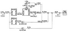
- FIG. 2schematically shows a computation procedure for ascertaining a slip torque M_TK currently transmitted by separating clutch 4 during a start of combustion engine 2 .
- combustion engine 2is started by closing separating clutch 4 during a pure electric driving operation.
- the measured speeds n_Eng of combustion engine 2 and n_ElM of electric machine 3 (in rpm)are used as input variables in the computation.
- a logical signal b_Startindicates an active start of combustion engine 2 .
- the signalis “true” as soon as combustion engine 2 has started (n_Eng>0) and as long as the absolute value of the speed difference between electric machine 3 and combustion engine 2 is greater than a specifiable threshold, which in this exemplary embodiment is 20 revolutions per minute (n_ElM ⁇ n_Eng>20 rpm).
- Speed n_Eng of combustion engine 2(in rpm) is first converted into an angular velocity om_Eng (in rad/s) using the constant multiplication factor Pi — 30_C.
- a “derivative” blockdifferentiates the angular velocity om_Eng and forms angular acceleration omp_Eng of combustion engine 2 .
- the differentiation of a measured variableusually increases signal noise. For this reason, it is followed by a “filter” block, which performs a first order filtering (PT 1 ) and ascertains a filtered angular acceleration omp_EngFlt of combustion engine 2 .
- filtered angular acceleration ompEngFltshould quickly approximate unfiltered angular acceleration omp_Eng.
- filtered angular acceleration omp_EngFltis advantageously initialized to a start value of omp_Eng averaged over multiple starting attempts and stored in the control system. The initialization occurs with the rising edge of signal b_Start.
- torque M_Theta required for accelerationis computed by multiplication with the reduced (converted for the crankshaft) mass inertia Theta_Eng_C of masses accelerated in combustion engine 2 such as the flywheel, crankshaft, pistons, ancillary units and the like). This torque forms a part of the slip torque M_TK transmitted by separating clutch 4 to combustion engine 2 when starting.
- the relative rotational angle phi_Engis ascertained by integration of angular velocity om_Eng and rises.
- the characteristic curve of compression torque M_Compr over relative rotational angle phi_Engis stored in a characteristics map M_Compr_CUR.
- a breakaway torquewhich is required to overcome the static friction or the mixed friction when the oil pressure is low, may be reproduced using the rotational angle-dependent compression torque M_Compr.
- the third component of torque M_TK transmitted by the separating clutch to the combustion engine when startingis formed by a speed-dependent or angular velocity-dependent torque loss M_Fric, which is produced by essentially internal mechanical friction and the charge exchange losses of combustion engine 2 .
- the characteristic curve of torque loss M_Fric over angular velocity om_Engis stored in a characteristics map M_Fric_CUR. For the sake of simplicity, a dependence on additional parameters, such as the oil temperature for example, is not taken into account in the exemplary embodiment shown in FIG. 2 .
- torque M_Theta required for acceleration, compression torque M_Compr, and torque loss M_Fricare added to form slip torque M_TK transmitted by separating clutch 4 .
- slip torque M_TKis compensated by electric machine 3 when starting, i.e., when starting, torque M_ElM of electric machine 3 is composed in sum of the torque desired by the driver M_Driver and slip torque M_TK.
- An adaptation of compression torque M_Compr and torque loss M_Fricis advantageous, e.g. by evaluating the characteristic curve of speed n_ElM in electric machine 3 in the starts.
- the characteristic curve of n_ElM while starting combustion engine 2may be analyzed for adapting the compression torque, while the characteristic curve after the start may be analyzed for adapting the torque loss.
- a decrease of n_ElM in active compensationmeans for example that the compression torque or torque loss stored in the control system is too small and must be increased by adaptation.
- the speed ratios on torque converter 5may be analyzed as well.
- an adaptation of the start value, stored in the control systemfor the initialization of filtered angular acceleration omp_EngFlt when starting.
- the adaptationsare possible because in the exemplary embodiment the slip torque M_TK, ascertained in accordance with the exemplary embodiments and/or exemplary methods of the present invention, is compensated by electric machine 3 and there is thus a feedback effect on speed n_ElM in electric machine 3 .
- the adaptationsresult in a comfortable driving behavior and additionally improve the accuracy in the determination of slip torque M_TK.
- compression torque M_Compr and the torque M_Theta required for accelerationare set to zero.
- the torque produced in the first ignitions of combustion engine 2 as a result of the combustionsis additionally included in the computation of slip torque M_TK transmitted by separating clutch 4 in order to achieve a correct compensation. A corresponding computation inclusion point is not shown in FIG. 2 .
- FIG. 4shows in an exemplary manner simulation results for highly idealized speed characteristics according to FIG. 3 .
- Speed n_ElMis a constant 1000 rpm, while speed n_Eng of combustion engine 2 when starting increases as a result of closing separating clutch 4 in ramp-shaped fashion from 0 rpm to 1000 rpm.
- filtered angular acceleration omp_EngFlt of combustion engine 2jumps to the start value stored in the control system and then approximates unfiltered angular acceleration omp_Eng.
- the slip torque M_Theta required for accelerationbehaves analogously.
- the control system of the present inventionmay also be used advantageously when stopping combustion engine 2 .
- slip torque M_TKis composed of slip torque M_Theta produced in the deceleration of the mass inertias of combustion engine 2 and torque loss M_Fric.
Landscapes
- Engineering & Computer Science (AREA)
- Transportation (AREA)
- Mechanical Engineering (AREA)
- Chemical & Material Sciences (AREA)
- Combustion & Propulsion (AREA)
- Automation & Control Theory (AREA)
- Hybrid Electric Vehicles (AREA)
- Hydraulic Clutches, Magnetic Clutches, Fluid Clutches, And Fluid Joints (AREA)
Abstract
Description
Claims (18)
Applications Claiming Priority (4)
| Application Number | Priority Date | Filing Date | Title |
|---|---|---|---|
| DE102007062796 | 2007-12-27 | ||
| DE102007062796ADE102007062796A1 (en) | 2007-12-27 | 2007-12-27 | Method for operating a hybrid drive device |
| DE102007062796.5 | 2007-12-27 | ||
| PCT/EP2008/065348WO2009083325A1 (en) | 2007-12-27 | 2008-11-12 | Method for operating a hybrid drive device |
Publications (2)
| Publication Number | Publication Date |
|---|---|
| US20110035085A1 US20110035085A1 (en) | 2011-02-10 |
| US9180768B2true US9180768B2 (en) | 2015-11-10 |
Family
ID=40361404
Family Applications (1)
| Application Number | Title | Priority Date | Filing Date |
|---|---|---|---|
| US12/810,692Expired - Fee RelatedUS9180768B2 (en) | 2007-12-27 | 2008-11-12 | Method for operating a hybrid drive device |
Country Status (4)
| Country | Link |
|---|---|
| US (1) | US9180768B2 (en) |
| EP (1) | EP2238339B1 (en) |
| DE (1) | DE102007062796A1 (en) |
| WO (1) | WO2009083325A1 (en) |
Families Citing this family (20)
| Publication number | Priority date | Publication date | Assignee | Title |
|---|---|---|---|---|
| DE102008041897A1 (en)* | 2008-09-09 | 2010-03-11 | Robert Bosch Gmbh | Method for operating a drive of a motor vehicle and drive device and electronic control unit |
| DE102008044016B4 (en)* | 2008-11-24 | 2025-07-31 | Robert Bosch Gmbh | Method for detecting an emerging torque for a hybrid drive |
| CN102245453B (en)* | 2010-03-01 | 2013-09-25 | 丰田自动车株式会社 | Power transmission control device |
| DE102010043591A1 (en)* | 2010-11-09 | 2012-05-10 | Zf Friedrichshafen Ag | Method for controlling a hybrid drive train of a motor vehicle |
| DE102010053950A1 (en) | 2010-12-09 | 2011-08-25 | Daimler AG, 70327 | Hybrid drive device has control or regulating unit, which is provided to control starting procedure of combustion engine and to provide switching signal for shifting process of transmission device |
| DE102011005469B4 (en)* | 2011-03-14 | 2020-03-19 | Zf Friedrichshafen Ag | Method for transferring a piston internal combustion engine of a vehicle drive train from a switched-off operating state to a switched-on operating state |
| DE102011015625A1 (en) | 2011-03-31 | 2011-11-10 | Daimler Ag | Hybrid drive device has controlling- and regulating unit, which is provided to control starting process of internal combustion engine, where controlling- and regulating unit has engine start function |
| DE102012007322A1 (en)* | 2012-04-12 | 2013-10-17 | Audi Ag | Method for operating a hybrid drive device |
| DE102012206157A1 (en)* | 2012-04-16 | 2013-10-17 | Zf Friedrichshafen Ag | Control device of a hybrid vehicle and method for operating the same |
| US9488267B2 (en)* | 2012-09-14 | 2016-11-08 | Ford Global Technologies, Llc | Line pressure control with input shaft torque measurement |
| US9278685B2 (en)* | 2012-12-10 | 2016-03-08 | Ford Global Technologies, Llc | Method and system for adapting operation of a hybrid vehicle transmission torque converter lockup clutch |
| DE102013226611A1 (en) | 2013-12-19 | 2015-06-25 | Robert Bosch Gmbh | Method for operating a hybrid drive device |
| DE112015005375A5 (en)* | 2014-11-28 | 2017-08-03 | Schaeffler Technologies AG & Co. KG | Method for starting an internal combustion engine of a hybrid vehicle |
| FR3037303B1 (en)* | 2015-06-10 | 2018-09-07 | Peugeot Citroen Automobiles Sa | DEVICE FOR MONITORING A TORQUE SETTING OF A HYBRID VEHICLE CLUTCH WHEN RE-STARTING THE THERMAL ENGINE |
| DE102015011583A1 (en) | 2015-09-04 | 2016-04-14 | Daimler Ag | Method for operating a clutch of a drive train for a motor vehicle |
| CN108700139B (en)* | 2016-02-19 | 2020-12-01 | 舍弗勒技术股份两合公司 | Method for calculating the slip power of a hybrid disconnect clutch |
| JP6390658B2 (en) | 2016-04-13 | 2018-09-19 | トヨタ自動車株式会社 | Vehicle control device |
| DE102016209939B4 (en)* | 2016-06-07 | 2018-04-05 | Schaeffler Technologies AG & Co. KG | Method for avoiding a critical driving situation in a vehicle with a hybrid drive |
| DE102017216392A1 (en)* | 2017-09-15 | 2019-03-21 | Zf Friedrichshafen Ag | Method and control device for operating a motor vehicle |
| JP2020040614A (en)* | 2018-09-13 | 2020-03-19 | マツダ株式会社 | Engine start control device for hybrid vehicle |
Citations (22)
| Publication number | Priority date | Publication date | Assignee | Title |
|---|---|---|---|---|
| DE4037092A1 (en) | 1990-11-22 | 1992-05-27 | Zahnradfabrik Friedrichshafen | METHOD FOR CONTROLLING THE TORQUE OF AN INTERNAL COMBUSTION ENGINE |
| DE4239711A1 (en) | 1992-11-26 | 1994-06-01 | Bosch Gmbh Robert | Vehicle control by exchange of data between subsystems via bus - requires control of driving unit by parameter evaluation w.r.t. quantity representing output power or capacity of engine |
| DE19504935A1 (en) | 1994-02-23 | 1995-08-24 | Luk Getriebe Systeme Gmbh | Clutch torque transfer system control method in e.g. motor vehicle |
| US5890992A (en)* | 1994-02-23 | 1999-04-06 | Luk Getriebe-Systeme Gmbh | Method of and apparatus for regulating the transmission of torque in power trains |
| US5941925A (en)* | 1992-11-26 | 1999-08-24 | Robert Bosch Gmbh | Method and arrangement for controlling a motor vehicle |
| US6018198A (en)* | 1997-08-29 | 2000-01-25 | Aisin Aw Co., Ltd. | Hybrid drive apparatus for vehicle |
| US6081042A (en)* | 1996-03-22 | 2000-06-27 | Toyota Jidosha Kabushiki Kaisha | Hybrid vehicle drive system including controllable device between engine and electric motor and vehicle drive wheels, and apparatus for controlling the device depending upon selected operation mode of the system |
| US6364807B1 (en)* | 2000-06-30 | 2002-04-02 | Ford Global Technologies, Inc. | Control strategy for a hybrid powertrain for an automotive vehicle |
| US20030088343A1 (en)* | 2001-11-05 | 2003-05-08 | Honda Giken Kogyo Kabushiki Kaisha | Vehicle drive apparatus, method and computer program |
| US20040157704A1 (en)* | 2001-07-12 | 2004-08-12 | Luk Lamellen Und Kupplungsbau Beteiligungs Kg | Method for adapting the adjustment of a clutch in an unconventional drive train of a vehicle |
| EP1505309A2 (en) | 2003-08-08 | 2005-02-09 | Renault s.a.s. | Control method for a drive unit including automated transmission and clutch |
| US20050256626A1 (en)* | 2004-05-14 | 2005-11-17 | Tung-Ming Hsieh | Method and apparatus to control hydraulic pressure in an electrically variable transmission |
| US20060243501A1 (en)* | 2005-04-28 | 2006-11-02 | Nissan Motor Co., Ltd. | Mode transition control system for hybrid vehicle |
| US20070056784A1 (en)* | 2005-09-08 | 2007-03-15 | Shinichiro Joe | Engine starting control device for a hybrid vehicle |
| US20070080005A1 (en)* | 2005-10-06 | 2007-04-12 | Nissan Motor Co., Ltd. | Hybrid vehicle drive control system |
| DE102006008640A1 (en) | 2006-02-24 | 2007-08-30 | Robert Bosch Gmbh | Hybrid drive method with direct starting supporting decoupler e.g. for internal combustion engines, involves having hybrid drive of vehicle with internal combustion engine and electric drive which has assigned traction battery |
| US20080183372A1 (en)* | 2007-01-31 | 2008-07-31 | Snyder Bryan R | Method and apparatus to determine pressure in an unfired cylinder |
| US20080275624A1 (en)* | 2007-05-03 | 2008-11-06 | Snyder Bryan R | Method and apparatus to control engine restart for a hybrid powertrain system |
| EP2008899A1 (en) | 2007-06-25 | 2008-12-31 | LuK Lamellen und Kupplungsbau Beteiligungs KG | Method and device for adapting friction coefficient to a friction clutch in a hybrid drive train |
| US20090017988A1 (en)* | 2007-07-05 | 2009-01-15 | Luk Lamellen Und Kupplungsbau Beteiligungs Kg | Method for controlling a starting clutch |
| US20090118914A1 (en)* | 2007-11-05 | 2009-05-07 | Gm Global Technology Operations, Inc. | Method for operating an internal combustion engine for a hybrid powertrain system |
| US20110040433A1 (en)* | 2007-12-20 | 2011-02-17 | Frank Steuernagel | Method and device for determining and predicting a starting torque or a starting torque characteristic curve required for starting an internal combustion engine |
- 2007
- 2007-12-27DEDE102007062796Apatent/DE102007062796A1/ennot_activeWithdrawn
- 2008
- 2008-11-12USUS12/810,692patent/US9180768B2/ennot_activeExpired - Fee Related
- 2008-11-12WOPCT/EP2008/065348patent/WO2009083325A1/enactiveApplication Filing
- 2008-11-12EPEP08868635.7Apatent/EP2238339B1/enactiveActive
Patent Citations (27)
| Publication number | Priority date | Publication date | Assignee | Title |
|---|---|---|---|---|
| DE4037092A1 (en) | 1990-11-22 | 1992-05-27 | Zahnradfabrik Friedrichshafen | METHOD FOR CONTROLLING THE TORQUE OF AN INTERNAL COMBUSTION ENGINE |
| US5383824A (en)* | 1990-11-22 | 1995-01-24 | Zahnradfabrik Friedrichshafen Ag | Process for controlling the torque of an internal combustion engine |
| DE4239711A1 (en) | 1992-11-26 | 1994-06-01 | Bosch Gmbh Robert | Vehicle control by exchange of data between subsystems via bus - requires control of driving unit by parameter evaluation w.r.t. quantity representing output power or capacity of engine |
| US5558178A (en)* | 1992-11-26 | 1996-09-24 | Robert Bosch Gmbh | Method and arrangement for controlling a motor vehicle |
| US5941925A (en)* | 1992-11-26 | 1999-08-24 | Robert Bosch Gmbh | Method and arrangement for controlling a motor vehicle |
| DE19504935A1 (en) | 1994-02-23 | 1995-08-24 | Luk Getriebe Systeme Gmbh | Clutch torque transfer system control method in e.g. motor vehicle |
| US5679091A (en)* | 1994-02-23 | 1997-10-21 | Luk Getriebe-Systeme Gmbh | Method of and apparatus for regulating the transmission of torque in power trains |
| US5890992A (en)* | 1994-02-23 | 1999-04-06 | Luk Getriebe-Systeme Gmbh | Method of and apparatus for regulating the transmission of torque in power trains |
| US6081042A (en)* | 1996-03-22 | 2000-06-27 | Toyota Jidosha Kabushiki Kaisha | Hybrid vehicle drive system including controllable device between engine and electric motor and vehicle drive wheels, and apparatus for controlling the device depending upon selected operation mode of the system |
| US6018198A (en)* | 1997-08-29 | 2000-01-25 | Aisin Aw Co., Ltd. | Hybrid drive apparatus for vehicle |
| US6364807B1 (en)* | 2000-06-30 | 2002-04-02 | Ford Global Technologies, Inc. | Control strategy for a hybrid powertrain for an automotive vehicle |
| US20040157704A1 (en)* | 2001-07-12 | 2004-08-12 | Luk Lamellen Und Kupplungsbau Beteiligungs Kg | Method for adapting the adjustment of a clutch in an unconventional drive train of a vehicle |
| US20030088343A1 (en)* | 2001-11-05 | 2003-05-08 | Honda Giken Kogyo Kabushiki Kaisha | Vehicle drive apparatus, method and computer program |
| EP1505309A2 (en) | 2003-08-08 | 2005-02-09 | Renault s.a.s. | Control method for a drive unit including automated transmission and clutch |
| US20050256626A1 (en)* | 2004-05-14 | 2005-11-17 | Tung-Ming Hsieh | Method and apparatus to control hydraulic pressure in an electrically variable transmission |
| US20060243501A1 (en)* | 2005-04-28 | 2006-11-02 | Nissan Motor Co., Ltd. | Mode transition control system for hybrid vehicle |
| US20070056784A1 (en)* | 2005-09-08 | 2007-03-15 | Shinichiro Joe | Engine starting control device for a hybrid vehicle |
| US20070080005A1 (en)* | 2005-10-06 | 2007-04-12 | Nissan Motor Co., Ltd. | Hybrid vehicle drive control system |
| DE102006008640A1 (en) | 2006-02-24 | 2007-08-30 | Robert Bosch Gmbh | Hybrid drive method with direct starting supporting decoupler e.g. for internal combustion engines, involves having hybrid drive of vehicle with internal combustion engine and electric drive which has assigned traction battery |
| US20090105038A1 (en)* | 2006-02-24 | 2009-04-23 | Ruediger Weiss | Hybrid drive having a separating clutch which assists a direct start |
| US20080183372A1 (en)* | 2007-01-31 | 2008-07-31 | Snyder Bryan R | Method and apparatus to determine pressure in an unfired cylinder |
| US20080275624A1 (en)* | 2007-05-03 | 2008-11-06 | Snyder Bryan R | Method and apparatus to control engine restart for a hybrid powertrain system |
| EP2008899A1 (en) | 2007-06-25 | 2008-12-31 | LuK Lamellen und Kupplungsbau Beteiligungs KG | Method and device for adapting friction coefficient to a friction clutch in a hybrid drive train |
| US20090011899A1 (en)* | 2007-06-25 | 2009-01-08 | Luk Lamellen Und Kupplungsbau Beteiligungs Kg | Method and device for adjusting the friction coefficient of a friction clutch situated in a hybrid power train |
| US20090017988A1 (en)* | 2007-07-05 | 2009-01-15 | Luk Lamellen Und Kupplungsbau Beteiligungs Kg | Method for controlling a starting clutch |
| US20090118914A1 (en)* | 2007-11-05 | 2009-05-07 | Gm Global Technology Operations, Inc. | Method for operating an internal combustion engine for a hybrid powertrain system |
| US20110040433A1 (en)* | 2007-12-20 | 2011-02-17 | Frank Steuernagel | Method and device for determining and predicting a starting torque or a starting torque characteristic curve required for starting an internal combustion engine |
Also Published As
| Publication number | Publication date |
|---|---|
| EP2238339A1 (en) | 2010-10-13 |
| DE102007062796A1 (en) | 2009-07-02 |
| EP2238339B1 (en) | 2017-08-16 |
| WO2009083325A1 (en) | 2009-07-09 |
| US20110035085A1 (en) | 2011-02-10 |
Similar Documents
| Publication | Publication Date | Title |
|---|---|---|
| US9180768B2 (en) | Method for operating a hybrid drive device | |
| US7353803B2 (en) | Misfire detection apparatus for internal combustion engine based on piston speed | |
| US8594913B2 (en) | Method and device for determining and predicting a starting torque or a starting torque characteristic curve required for starting an internal combustion engine | |
| US8666620B2 (en) | Method for controlling an automated geared transmission | |
| US9797324B2 (en) | Method and device for operating an internal combustion engine | |
| CN102278223B (en) | Apparatus and method for estimating stopped engine crank angle | |
| GB2326251A (en) | Damping torque reversal jerkiness in an internal combustion engine | |
| JPH0715263B2 (en) | Turbocharger controller | |
| JP2008088939A (en) | Stop position control device for internal combustion engine | |
| EP3575167B1 (en) | Driving force control method and device for hybrid vehicle | |
| US11260846B2 (en) | Driving force control method and device for hybrid vehicle | |
| CN109795470B (en) | Active vibration reduction method of power system based on engine instantaneous torque observer | |
| US11312355B2 (en) | Driving force control method and device for hybrid vehicle | |
| US11235749B2 (en) | Driving force control method and device for hybrid vehicle | |
| US8280576B2 (en) | Method for operating an automotive drive | |
| JP2001020803A (en) | Control method and system of vehicle driving unit | |
| JP4760423B2 (en) | Oil deterioration judgment device for internal combustion engine | |
| US11121651B2 (en) | Driving force control method and device for hybrid vehicle | |
| EP1072778B1 (en) | Method for controlling idling in an internal combustion engine | |
| US11230281B2 (en) | Driving force control method and device for hybrid vehicle | |
| JP2005264813A (en) | Rotation angle detection device for internal combustion engine | |
| KR102842798B1 (en) | Diagnosis method for cvvt apparatus | |
| JP4738473B2 (en) | Torque control device for internal combustion engine | |
| JP2020148145A (en) | Engine control device | |
| US10190562B2 (en) | Engine start determining apparatus |
Legal Events
| Date | Code | Title | Description |
|---|---|---|---|
| AS | Assignment | Owner name:ROBERT BOSCH GMBH, GERMANY Free format text:ASSIGNMENT OF ASSIGNORS INTEREST;ASSIGNOR:FALKENSTEIN, JENS-WERNER;REEL/FRAME:025127/0004 Effective date:20100930 | |
| ZAAA | Notice of allowance and fees due | Free format text:ORIGINAL CODE: NOA | |
| ZAAB | Notice of allowance mailed | Free format text:ORIGINAL CODE: MN/=. | |
| ZAAA | Notice of allowance and fees due | Free format text:ORIGINAL CODE: NOA | |
| STCF | Information on status: patent grant | Free format text:PATENTED CASE | |
| MAFP | Maintenance fee payment | Free format text:PAYMENT OF MAINTENANCE FEE, 4TH YEAR, LARGE ENTITY (ORIGINAL EVENT CODE: M1551); ENTITY STATUS OF PATENT OWNER: LARGE ENTITY Year of fee payment:4 | |
| FEPP | Fee payment procedure | Free format text:MAINTENANCE FEE REMINDER MAILED (ORIGINAL EVENT CODE: REM.); ENTITY STATUS OF PATENT OWNER: LARGE ENTITY | |
| LAPS | Lapse for failure to pay maintenance fees | Free format text:PATENT EXPIRED FOR FAILURE TO PAY MAINTENANCE FEES (ORIGINAL EVENT CODE: EXP.); ENTITY STATUS OF PATENT OWNER: LARGE ENTITY | |
| STCH | Information on status: patent discontinuation | Free format text:PATENT EXPIRED DUE TO NONPAYMENT OF MAINTENANCE FEES UNDER 37 CFR 1.362 | |
| FP | Lapsed due to failure to pay maintenance fee | Effective date:20231110 |