US9180233B2 - Systems and methods for subcutaneous administration of reduced pressure employing reconfigurable lumens - Google Patents
Systems and methods for subcutaneous administration of reduced pressure employing reconfigurable lumensDownload PDFInfo
- Publication number
- US9180233B2 US9180233B2US13/292,880US201113292880AUS9180233B2US 9180233 B2US9180233 B2US 9180233B2US 201113292880 AUS201113292880 AUS 201113292880AUS 9180233 B2US9180233 B2US 9180233B2
- Authority
- US
- United States
- Prior art keywords
- lumen
- applicator
- tissue site
- apertures
- activation member
- Prior art date
- Legal status (The legal status is an assumption and is not a legal conclusion. Google has not performed a legal analysis and makes no representation as to the accuracy of the status listed.)
- Active, expires
Links
Images


Classifications
- A—HUMAN NECESSITIES
- A61—MEDICAL OR VETERINARY SCIENCE; HYGIENE
- A61M—DEVICES FOR INTRODUCING MEDIA INTO, OR ONTO, THE BODY; DEVICES FOR TRANSDUCING BODY MEDIA OR FOR TAKING MEDIA FROM THE BODY; DEVICES FOR PRODUCING OR ENDING SLEEP OR STUPOR
- A61M1/00—Suction or pumping devices for medical purposes; Devices for carrying-off, for treatment of, or for carrying-over, body-liquids; Drainage systems
- A61M1/71—Suction drainage systems
- A61M1/74—Suction control
- A61M1/0084—
- A61M1/0031—
- A—HUMAN NECESSITIES
- A61—MEDICAL OR VETERINARY SCIENCE; HYGIENE
- A61M—DEVICES FOR INTRODUCING MEDIA INTO, OR ONTO, THE BODY; DEVICES FOR TRANSDUCING BODY MEDIA OR FOR TAKING MEDIA FROM THE BODY; DEVICES FOR PRODUCING OR ENDING SLEEP OR STUPOR
- A61M1/00—Suction or pumping devices for medical purposes; Devices for carrying-off, for treatment of, or for carrying-over, body-liquids; Drainage systems
- A61M1/71—Suction drainage systems
- A61M1/74—Suction control
- A61M1/743—Suction control by changing the cross-section of the line, e.g. flow regulating valves
- A—HUMAN NECESSITIES
- A61—MEDICAL OR VETERINARY SCIENCE; HYGIENE
- A61M—DEVICES FOR INTRODUCING MEDIA INTO, OR ONTO, THE BODY; DEVICES FOR TRANSDUCING BODY MEDIA OR FOR TAKING MEDIA FROM THE BODY; DEVICES FOR PRODUCING OR ENDING SLEEP OR STUPOR
- A61M1/00—Suction or pumping devices for medical purposes; Devices for carrying-off, for treatment of, or for carrying-over, body-liquids; Drainage systems
- A61M1/84—Drainage tubes; Aspiration tips
- A61M1/85—Drainage tubes; Aspiration tips with gas or fluid supply means, e.g. for supplying rinsing fluids or anticoagulants
- A—HUMAN NECESSITIES
- A61—MEDICAL OR VETERINARY SCIENCE; HYGIENE
- A61M—DEVICES FOR INTRODUCING MEDIA INTO, OR ONTO, THE BODY; DEVICES FOR TRANSDUCING BODY MEDIA OR FOR TAKING MEDIA FROM THE BODY; DEVICES FOR PRODUCING OR ENDING SLEEP OR STUPOR
- A61M1/00—Suction or pumping devices for medical purposes; Devices for carrying-off, for treatment of, or for carrying-over, body-liquids; Drainage systems
- A61M1/90—Negative pressure wound therapy devices, i.e. devices for applying suction to a wound to promote healing, e.g. including a vacuum dressing
- A61M1/91—Suction aspects of the dressing
- A61M1/916—Suction aspects of the dressing specially adapted for deep wounds
- A—HUMAN NECESSITIES
- A61—MEDICAL OR VETERINARY SCIENCE; HYGIENE
- A61M—DEVICES FOR INTRODUCING MEDIA INTO, OR ONTO, THE BODY; DEVICES FOR TRANSDUCING BODY MEDIA OR FOR TAKING MEDIA FROM THE BODY; DEVICES FOR PRODUCING OR ENDING SLEEP OR STUPOR
- A61M1/00—Suction or pumping devices for medical purposes; Devices for carrying-off, for treatment of, or for carrying-over, body-liquids; Drainage systems
- A61M1/90—Negative pressure wound therapy devices, i.e. devices for applying suction to a wound to promote healing, e.g. including a vacuum dressing
- A61M1/92—Negative pressure wound therapy devices, i.e. devices for applying suction to a wound to promote healing, e.g. including a vacuum dressing with liquid supply means
- A—HUMAN NECESSITIES
- A61—MEDICAL OR VETERINARY SCIENCE; HYGIENE
- A61M—DEVICES FOR INTRODUCING MEDIA INTO, OR ONTO, THE BODY; DEVICES FOR TRANSDUCING BODY MEDIA OR FOR TAKING MEDIA FROM THE BODY; DEVICES FOR PRODUCING OR ENDING SLEEP OR STUPOR
- A61M1/00—Suction or pumping devices for medical purposes; Devices for carrying-off, for treatment of, or for carrying-over, body-liquids; Drainage systems
- A61M1/90—Negative pressure wound therapy devices, i.e. devices for applying suction to a wound to promote healing, e.g. including a vacuum dressing
- A61M1/96—Suction control thereof
- A61M1/0088—
- A—HUMAN NECESSITIES
- A61—MEDICAL OR VETERINARY SCIENCE; HYGIENE
- A61M—DEVICES FOR INTRODUCING MEDIA INTO, OR ONTO, THE BODY; DEVICES FOR TRANSDUCING BODY MEDIA OR FOR TAKING MEDIA FROM THE BODY; DEVICES FOR PRODUCING OR ENDING SLEEP OR STUPOR
- A61M1/00—Suction or pumping devices for medical purposes; Devices for carrying-off, for treatment of, or for carrying-over, body-liquids; Drainage systems
- A61M1/84—Drainage tubes; Aspiration tips
- A61M1/87—Details of the aspiration tip, not otherwise provided for
- A—HUMAN NECESSITIES
- A61—MEDICAL OR VETERINARY SCIENCE; HYGIENE
- A61M—DEVICES FOR INTRODUCING MEDIA INTO, OR ONTO, THE BODY; DEVICES FOR TRANSDUCING BODY MEDIA OR FOR TAKING MEDIA FROM THE BODY; DEVICES FOR PRODUCING OR ENDING SLEEP OR STUPOR
- A61M5/00—Devices for bringing media into the body in a subcutaneous, intra-vascular or intramuscular way; Accessories therefor, e.g. filling or cleaning devices, arm-rests
- A61M5/14—Infusion devices, e.g. infusing by gravity; Blood infusion; Accessories therefor
- A61M2005/1401—Functional features
- A61M2005/1403—Flushing or purging
- A—HUMAN NECESSITIES
- A61—MEDICAL OR VETERINARY SCIENCE; HYGIENE
- A61M—DEVICES FOR INTRODUCING MEDIA INTO, OR ONTO, THE BODY; DEVICES FOR TRANSDUCING BODY MEDIA OR FOR TAKING MEDIA FROM THE BODY; DEVICES FOR PRODUCING OR ENDING SLEEP OR STUPOR
- A61M2205/00—General characteristics of the apparatus
- A61M2205/18—General characteristics of the apparatus with alarm
- A—HUMAN NECESSITIES
- A61—MEDICAL OR VETERINARY SCIENCE; HYGIENE
- A61M—DEVICES FOR INTRODUCING MEDIA INTO, OR ONTO, THE BODY; DEVICES FOR TRANSDUCING BODY MEDIA OR FOR TAKING MEDIA FROM THE BODY; DEVICES FOR PRODUCING OR ENDING SLEEP OR STUPOR
- A61M2205/00—General characteristics of the apparatus
- A61M2205/33—Controlling, regulating or measuring
- A61M2205/3331—Pressure; Flow
- A—HUMAN NECESSITIES
- A61—MEDICAL OR VETERINARY SCIENCE; HYGIENE
- A61M—DEVICES FOR INTRODUCING MEDIA INTO, OR ONTO, THE BODY; DEVICES FOR TRANSDUCING BODY MEDIA OR FOR TAKING MEDIA FROM THE BODY; DEVICES FOR PRODUCING OR ENDING SLEEP OR STUPOR
- A61M2209/00—Ancillary equipment
- A61M2209/10—Equipment for cleaning
- A—HUMAN NECESSITIES
- A61—MEDICAL OR VETERINARY SCIENCE; HYGIENE
- A61M—DEVICES FOR INTRODUCING MEDIA INTO, OR ONTO, THE BODY; DEVICES FOR TRANSDUCING BODY MEDIA OR FOR TAKING MEDIA FROM THE BODY; DEVICES FOR PRODUCING OR ENDING SLEEP OR STUPOR
- A61M2210/00—Anatomical parts of the body
- A61M2210/02—Bones
Definitions
- the present disclosurerelates generally to medical treatment systems and, more particularly, but not by way of limitation, to systems, methods, and devices for the subcutaneous administration of reduced pressure that include reconfigurable lumens.
- a system for providing reduced pressure to a subcutaneous tissue site and removing fluids from the subcutaneous tissue siteincludes a multi-lumen applicator for distributing reduced pressure at the subcutaneous tissue site, a reduced-pressure delivery conduit fluidly coupled to the multi-lumen applicator, a reduced-pressure source coupled to the reduced-pressure delivery conduit, and a purging unit fluidly coupled to the reduced-pressure delivery conduit.
- the multi-lumen applicatorincludes an applicator body formed with a plurality of apertures, a first lumen initially fluidly configured to receive liquids from the tissue site through the plurality of apertures, a second lumen initially configured to provide a purging fluid to the first lumen, and a first frangible member disposed between the first lumen and second lumen.
- the first frangible memberis configured to rupture when exposed to a pressure greater than a first threshold pressure differential whereby at least a portion of the second lumen and a portion of the first lumen become fluidly coupled.
- a system for providing reduced pressure to a subcutaneous tissue siteincludes a multi-lumen applicator for distributing reduced pressure at the subcutaneous tissue site, a reduced-pressure delivery conduit fluidly coupled to the multi-lumen applicator, a reduced-pressure source coupled to the reduced-pressure delivery conduit, and a purging unit fluidly coupled to the reduced-pressure delivery conduit.
- the multi-lumen applicatorincludes an applicator body formed with a plurality of apertures, a first lumen initially fluidly configured to receive liquids from the tissue site through the plurality of apertures, a second lumen initially configured to provide a purging fluid to the first lumen, and an activation member disposed between the first lumen and second lumen.
- the activation memberis configured to fluidly couple, when activated, at least a portion of the second lumen and a portion of the first lumen whereby at least a portion of the second lumen transports the liquids from the tissue site over at least a portion of the second lumen.
- a method for providing reduced pressure to a subcutaneous tissue siteincludes providing multi-lumen applicator for distributing reduced pressure at the subcutaneous tissue site.
- the multi-lumen applicatorincludes an applicator body formed with a plurality of apertures and at least a first lumen and a second lumen, and at least one frangible member.
- the methodfurther includes disposing the multi-lumen applicator proximate to the subcutaneous tissue site, removing fluids from the subcutaneous tissue site through the first lumen, rupturing the at least one frangible member to reconfigure functionality of at least a portion the second lumen, and removing fluids from the subcutaneous tissue site at least partially through the second lumen after rupturing the at least one frangible member.
- a multi-lumen applicator for delivering reduced pressure to a tissue site and receiving liquidsincludes an applicator body having a distal end and a proximal end and formed with a plurality of apertures for receiving liquid from the tissue site and for delivering reduced pressure, a first lumen fluidly coupled to the plurality of apertures, a first activation member having at least a closed position and an open position, and a second lumen fluidly coupled to the plurality of apertures when the first activation member is in the open position but not when in the closed position.
- the configurationis such that when the first activation member is moved to the open position, the second lumen is fluidly coupled to the plurality of apertures.
- a method for providing reduced pressure to a subcutaneous tissue siteincludes providing a multi-lumen applicator for distributing reduced pressure at the subcutaneous tissue site.
- the multi-lumen applicatorincludes an applicator body formed with a plurality of apertures, a purge lumen, a first lumen fluidly coupled to the plurality of apertures and to the purge lumen, an activation member operable to move from a closed position to an open position when activated, and a second lumen fluidly coupled to the purge lumen when the activation member is in the open position.
- the methodfurther includes disposing the multi-lumen applicator proximate to the subcutaneous tissue site, removing fluids from the subcutaneous tissue site through the first lumen, activating the activation member of the multi-lumen applicator such that the second lumen is fluidly coupled to the purge lumen, and removing fluids from the subcutaneous tissue site at least partially through the second lumen after activating the activation member.
- a multi-lumen applicator for delivering reduced pressure to a tissue site and receiving liquidsincludes an applicator body having a distal end and a proximal end and formed with a first plurality of apertures and a second plurality of apertures for receiving liquid from the tissue site and for delivering reduced pressure, a first lumen fluidly coupled to the first plurality of apertures, a second lumen fluid coupled to the second plurality of apertures, and a first plurality of activation members coupled over the second plurality of apertures.
- the first plurality of activation membersare operable to move from a closed position to an open position when activated.
- a multi-lumen applicator for delivering reduced pressure to a subcutaneous tissue siteincludes an applicator body having a proximal end and a distal end and formed with plurality of apertures for distributing reduced pressure, a first lumen fluidly coupled to the plurality of apertures, a second lumen fluidly coupled to the plurality of apertures, and a removal filament member disposed within the second lumen and operable to be removed when fluid flow in the second lumen is desired.
- a system for delivering reduced pressure to a subcutaneous tissue siteincludes a connector and a multi-lumen applicator.
- the multi-lumen applicatorincludes an applicator body having a proximal end and a distal end and formed with plurality of apertures for distributing reduced pressure, a first lumen fluidly coupled to at least a portion of the plurality of apertures and to the connector, and a second lumen fluidly coupled to at least a portion of the plurality of apertures and to the connector.
- the systemfurther includes a reduced-pressure source fluidly coupled to the connector, a purge unit fluidly coupled to the connector, and a controller coupled to the connector.
- the controlleris operable to initially couple the first lumen to the reduced-pressure source to provide reduced pressure thereby to at least a portion of the plurality of apertures, initially fluidly couple the second lumen to the purge unit, and when the first lumen becomes occluded, couple the first lumen to the purge unit and the second lumen to the reduced-pressure source.
- a method for delivering reduced pressure to a subcutaneous tissue siteincludes providing a multi-lumen applicator for distributing reduced pressure at the subcutaneous tissue site
- the multi-lumen applicatorincludes an applicator body formed with a plurality of apertures, a first lumen fluidly coupled to at least a portion of the plurality of apertures, and a second lumen fluidly coupled to at least a portion of the plurality of apertures.
- the methodfurther includes coupling the first lumen to a reduced-pressure source, coupling the second lumen to a purge unit, disposing the multi-lumen applicator proximate to the subcutaneous tissue site, removing fluids from the subcutaneous tissue site through the first lumen, and when the first lumen becomes substantially blocked, coupling the second lumen to the reduced-pressure source and the first lumen to the purge unit.
- a system for delivering reduced pressure to a subcutaneous tissue siteincludes a multi-lumen applicator comprising.
- the multi-lumen applicatorincludes an applicator body having a proximal end and a distal end and formed with plurality of apertures for distributing reduced pressure, a first lumen fluidly coupled to at least a portion of the plurality of apertures, and a second lumen fluidly coupled to at least a portion of the plurality of apertures.
- the systemfurther includes a reduced-pressure source fluidly coupled to the first lumen, and a blockage-removal device initially disposed within the first lumen. The blockage-removal device is operable to remove a blockage from within the first lumen when the blockage-removal device is activated.
- FIG. 1is a schematic diagram, with a portion shown in cross section, of an illustrative embodiment of a system for providing reduced pressure to a subcutaneous tissue site and for removing fluids from the subcutaneous tissue site;
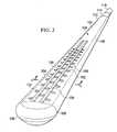
- FIG. 2is a schematic, perspective view of an illustrative embodiment of a multi-lumen applicator
- FIG. 3is a longitudinal cross section of the multi-lumen applicator of FIG. 2 showing a distal end;
- FIG. 4is a lateral cross section of the multi-lumen applicator of FIG. 2 taken along line 4 - 4 ;
- FIGS. 5A-5Care schematic cross sections of an illustrative embodiment of a multi-lumen applicator that includes a first activation member shown in different states;
- FIG. 6is a schematic longitudinal cross section of two lumens that may be included in an illustrative embodiment of a multi-lumen applicator
- FIG. 7is a schematic, plan view of an illustrative embodiment of a multi-lumen applicator for use as part of a system for providing reduced pressure to subcutaneous tissue site and for removing fluids from the subcutaneous tissue site;
- FIG. 8is a schematic lateral cross section taken along line 8 - 8 of the multi-lumen applicator of FIG. 7 ;
- FIG. 9is a schematic, lateral cross section taken along line 9 - 9 in FIG. 7 of the illustrative, non-limiting multi-lumen applicator;
- FIG. 10is a schematic, perspective view (with a portion shown in cross section) of another illustrative embodiment of a multi-lumen applicator for distributing reduced pressure that may be used as an aspect of a system for providing reduced pressure to a subcutaneous tissue site and for removing fluids from the subcutaneous tissue site;
- FIG. 11is a schematic diagram, with a portion shown in perspective view, of an illustrative embodiment of a system for delivering reduced pressure to a subcutaneous tissue site;
- FIG. 12is a schematic, lateral cross section of the multi-lumen applicator of FIG. 11 taken along line 12 - 12 ;
- FIG. 13is a longitudinal cross section taken in part along line 13 - 13 of the multi-lumen applicator of FIG. 11 ;
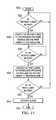
- FIG. 14is a schematic diagram showing an illustrative embodiment of a process for a controller used as part of a system for delivering reduced pressure to a subcutaneous tissue site;
- FIG. 15is a schematic, longitudinal cross section of a distal portion of an illustrative embodiment of a multi-lumen applicator shown with a wire cleaning element;
- FIG. 16is a schematic, longitudinal cross section of a distal portion of an illustrative embodiment of a multi-lumen applicator shown with a elongated brush;
- FIG. 17is a schematic, longitudinal cross section of a distal portion of an illustrative embodiment of a multi-lumen applicator shown with a removable water jet;
- FIG. 18is a schematic, longitudinal cross section of a distal portion of an illustrative embodiment of a multi-lumen applicator shown with a purging implement;
- FIG. 19is a schematic, longitudinal cross section of a distal portion of an illustrative embodiment of a multi-lumen applicator shown with a cytology brush.
- Providing reduced pressure to a subcutaneous tissue sitemay assist with removing fluids, e.g., ascites or exudates, or enhance tissue growth as an aspect of reduced pressure therapy.
- fluidse.g., ascites or exudates
- enhance tissue growthas an aspect of reduced pressure therapy.
- “or”does not require mutual exclusivity.
- a multi-lumen applicatoris used.
- blockage of lumensmay occur and pose a problem to the ongoing treatment.
- the lumensmay be reconfigured relative to the blockage in order to restore flow of reduced pressure to the subcutaneous tissue site or to remove the blockage.
- the blockagemay be removed using a blockage-removal device.
- the subcutaneous tissue site 102may be, for example, a defect 104 in or on a bone 106 (e.g., a fractured bone).
- the subcutaneous tissue site 102may be any site that may benefit from treatment with reduced pressure to remove fluids or as an aspect of reduced pressure therapy.
- the subcutaneous tissue site 102may be the bodily tissue of any human, animal, or other organism, including bone tissue, adipose tissue, muscle tissue, vascular tissue, connective tissue, cartilage, tendons, ligaments, or any other tissue.
- the system 100includes a multi-lumen applicator 108 that is inserted into the patient 110 and placed proximate to the subcutaneous tissue site 102 .
- the multi-lumen applicator 108is shown having been inserted through epidermis 112 , dermis 114 , and into subcutaneous tissue 116 .
- the multi-lumen applicator 108is positioned proximate to the subcutaneous tissue site 102 .
- the multi-lumen applicator 108is fluidly coupled to a reduced-pressure delivery conduit 118 , which may be a multi-lumen conduit that has lumens coordinated and fluidly coupled to the multiple lumens of the multi-lumen applicator 108 .
- the reduced-pressure delivery conduit 118may be fluidly coupled to a connector 120 that may facilitate connecting multiple lumens to the multiple lumens of the reduced-pressure delivery conduit 118 .
- a reduced-pressure source 122is fluidly coupled by a conduit 124 to the connector 120 to provide reduced pressure thereto.
- the reduced-pressure source 122may include a reduced-pressure supply portion 126 and a fluid reservoir 128 .
- the reduced-pressure supply portion 126may be a vacuum pump, wall suction, or any other source of reduced pressure.
- the fluid reservoir 128may provide a place to receive and retain fluids delivered from the patient 110 .
- Reduced pressureis typically a pressure less than the ambient pressure at a tissue site that is being subjected to treatment. In most cases, this reduced pressure will be less than the atmospheric pressure at which the patient is located. Alternatively, the reduced pressure may be less than a hydrostatic pressure at the tissue site. Unless otherwise indicated, quantitative values of pressure stated herein are gauge pressures.
- the reduced pressure deliveredmay be constant or varied (patterned or random) and may be delivered continuously or intermittently.
- vacuum and negative pressuremay be used to describe the pressure applied to the tissue site, the actual pressure applied to the tissue site may be more than the pressure normally associated with a complete vacuum.
- an increase in reduced pressure or vacuum pressuretypically refers to a relative reduction in absolute pressure. For example, going from ⁇ 50 mm Hg to ⁇ 100 mm Hg may be referred to as an increase in reduced pressure, but on an absolute pressure scale it is a decrease in pressure.
- a purging unit 130may be fluidly coupled by a conduit 132 to the connector 120 .
- the purging unit 130may provide atmospheric air or another purging gas or pressurized gas to the multi-lumen applicator 108 in order to avoid or remove blockages therein.
- the purge gas provided by the purging unit 130may be at an elevated pressure with respect to atmosphere or relative to the operational pressure of the system 100 .
- a liquid source 134may be fluidly coupled by a conduit 136 to the connector 120 .
- the liquid source 134may be used to provide a liquid purge to the multi-lumen applicator 108 or may be used to provide a treatment liquid, or therapeutic liquid, to the multi-lumen applicator 108 and ultimately to the subcutaneous tissue site 102 .
- a controller 138may be coupled by coupling lines 140 , 142 and 144 to the reduced-pressure source 122 , purging unit 130 , and liquid source 134 , respectively.
- the controller 138may include a microprocessor, memory, and other components for providing control to the reduced-pressure source 122 , purging unit 130 , and liquid supply 134 .
- the controller 138may also be coupled to the connector 120 to control valves within the connector 120 as shown in the illustrative embodiment of FIG. 11 .
- the multi-lumen applicator 108is formed with an applicator body 146 , which has a first side 148 and a second, tissue-facing side 150 .
- the multi-lumen applicator 108may be formed by injection molding or other techniques.
- the multi-lumen applicator 108may also be extruded into parts and then bonded or otherwise coupled to form an integral unit.
- the multi-lumen applicator 108may be extruded and then undergo a secondary controlled melt “tipping” process to form an integral unit.
- the multi-lumen applicator 108may be made from a flexible or semi-rigid material.
- the multi-lumen applicator 108may be made from any medical-grade polymer, such as polyurethane.
- the multi-lumen applicator 108is made from a material with a stiffness of approximately 80 Shore A, but other stiffnesses may be used.
- a coatingmay be added to the multi-lumen applicator 108 to avoid material buildup on the multi-lumen applicator 108 .
- a plurality of apertures 152are formed on the second, tissue-facing side 150 of the applicator body 146 for providing reduced pressure to the subcutaneous tissue site 102 . While the apertures 152 are shown in a symmetrically spaced pattern, it should be understood that the apertures 152 may be formed with any pattern or with a random placement.
- a plurality of manifold surface features 154may be formed on the second, tissue-facing side 150 .
- the plurality of manifold surface features 154may include a plurality of standoffs or offsets 156 .
- the plurality of offsets 156may be formed integrally with or coupled to the second, tissue-facing side 150 of the applicator body 146 .
- the offsets 156may be any surface feature creating effective flow channels between the second, tissue-facing side 150 and the tissue site.
- the manifold surface features 154may detach from the applicator body 146 when the multi-lumen applicator 108 is percutaneously removed, and the manifold surface features 154 may be bioresorbable.
- the plurality of apertures 152are fluidly coupled to the first lumen 158 that is formed in the applicator body 146 .
- the first lumen 158may be fluidly coupled to the apertures 152 by a plurality of conduits 160 .
- the first lumen 158extends the longitudinal length of the applicator body 146 .
- the first lumen 158may initially be used as an evacuation lumen to deliver reduced pressure to the plurality of apertures 152 and to receive and transport fluids from the subcutaneous tissue site 102 .
- the applicator body 146is also formed with a second lumen 162 and may have a third lumen 164 or even more lumens.
- the second lumen 162 and third lumen 164also extend the longitudinal length of the applicator body 146 .
- the second lumen 162 and third lumen 164may initially be used as purge lumens, or vent lumens. While this illustrative embodiment shows two purge lumens, it should be understood that any number of purge lumens may be used.
- the second lumen 162 and third lumen 164are shown symmetrically spaced about the first lumen 158 , and while the symmetric orientation may enhance performance, other orientations may be used.
- Additional lumenssuch as a pressure sensing lumen (not explicitly shown), may be included within the applicator body 146 .
- the purge lumensmay also serve as pressure sensing lumens. It should be noted that although a slightly elliptical or triangular shape is presented, the cross sectional shape of the applicator body 146 may be any of those previously mentioned or even irregular or other shapes.
- an end cap 168is formed or coupled.
- the end cap 168is formed with a header space 170 that allows the second lumen 162 and the third lumen 164 (and any additional lumens) to be fluidly coupled to the first lumen 158 .
- the end cap 168is formed integrally to or as part of the applicator body 146 and, thus, avoids the risk of the end cap 168 becoming dislodged during removal from the patient 110 .
- a proximal end 172FIG.
- a connecting element, or connector 174may be coupled to provide easy connection with the reduced-pressure delivery conduit 118 , which in turn is fluidly coupled to the reduced-pressure source 122 and also to the purging unit 130 or liquid source 134 .
- the multi-lumen applicator 108has provisions to reconfigure lumens, e.g., the first lumen 158 , second lumen 162 , and third lumen 164 , in order to restore flow through the apertures 152 .
- a first port 176is formed between the first lumen 158 and the second lumen 162 .
- Porttypically refers to an open flow path either between two lumens or a lumen and an exterior of the multi-lumen applicator 108 .
- the first port 176fluidly couples the first lumen 158 and the second lumen 162 when a first activation member 178 is in an open, or activated, position.
- the first activation member 178may be any member that provides a closed position in one state and an open position in another state that allows flow.
- the first activation member 180may be a first frangible member 180 as shown in FIG. 3 in the closed position.
- frangibleis used generally to indicate a material that fails, ruptures, tears, or dissolves in a predictable manner. The frangible material fails, ruptures, tears, or dissolves in a repeatable manner between devices.
- the first frangible member 180may be a frangible disc or frangible port cover, which may be a piece of material covering a port that is designed to rupture or open at a first threshold pressure differential or to dissolve and thereby open after being exposed to a liquid for at least a threshold time.
- the activation member 178may be formed from a polylactic acid (PLA), polyglycolic acid (PGA), polyactic co-glycolic acid (PLGA), hydrogel, or cross-linked or hardened gelatine, or other suitable material.
- the first activation member 178may be a valve with a remote attachment, e.g., a line, that can be pulled to open the first activation member 178 .
- the first activation member 178may be a plug in a port that under pressure is released from the port and is removed.
- a second port 182is formed between the first lumen 158 and the third lumen 164 .
- the second port 182fluidly couples the first lumen 158 and the third lumen 164 when a second activation member 184 is in an open position.
- the second activation member 184may be a second frangible member 186 or other device analogous to those mentioned for first activation member 180 .
- the multi-lumen applicator 108may be inserted surgically or using minimally invasive surgery into the patient. Typically, the multi-lumen applicator 108 is removed percutaneously after use or in one embodiment may be bio-absorbable and left in place to absorb. In one illustrative embodiment in which it is desirable to provide reduced-pressure treatment with the multi-lumen applicator 108 for an extended period of time, e.g., 24 hours, the multi-lumen applicator 108 addresses blocks or the possibility of blocks by reconfiguring lumens during use Thus, after the multi-lumen applicator 108 is inserted, and reduced pressure is supplied to the subcutaneous tissue site 102 , flow may continue for a first period of time.
- the first activation member 178may be activated to open a flow path that reconfigures flow by reconfiguring the lumens 158 , 162 , or 164 .
- the reconfigurationincreases the likelihood that the system 100 will continue to operate with flow for the desired time duration.
- a number of illustrative, non-limiting examples of how lumens may be reconfigured or how blockages may be removedwill be presented.
- FIGS. 5A-5Can illustrative embodiment of a multi-lumen applicator 108 is presented to show how lumens, e.g., lumens 158 and 162 , may be reconfigured according to one illustrative embodiment.
- the multi-lumen applicator 108is shown with only two lumens: a first lumen 158 and a second lumen 162 . It should be understood that other lumens or additional lumens may be involved.
- the multi-lumen applicator 108 in FIG. 5Ashows an initial state in which reduced pressure is delivered to the first lumen 158 thereby causing a flow 188 of fluid in an ante grade direction.
- the first lumen 158 in this initial conditionserves as an evacuation lumen.
- the multi-lumen applicator 108also includes the second lumen 162 that initially serves as a purge lumen providing a purge fluid, such as air, to the first lumen 158 to inhibit blocking or eliminate blocking.
- the purge fluidmay be provided on a periodic basis. It should be appreciated that the second lumen 162 provides a purging fluid that travels through a head space 170 at a distal end 166 to avoid blockages.
- reduced pressureis distributed to a plurality of apertures 152 in an applicator body 146 .
- Fluide.g., wound effluent
- tissue sitee.g., the subcutaneous tissue site 102 in FIG. 1
- fluid reservoire.g., the fluid reservoir 128 in FIG. 1 .
- Normal operationmay involve, for example, and not by way of limitation, a reduced pressure in the range of ⁇ 100 mm Hg ( ⁇ 13.3 kPa) to ⁇ 200 mm Hg ( ⁇ 26.6 kPa).
- a first port 176may be formed as an aspect of a wall 159 between the first lumen 158 and second lumen 162 .
- the first port 176is controlled by a first activation member 178 that has a closed position as shown in FIGS. 5A-B and an open position as shown in FIG. 5C .
- the first activation member 178assumes the open position when activated.
- the first activation member 178may be, for example, a first frangible member 180 .
- a blockage 190may result within the first lumen 158 .
- the blockage 190may inhibit or completely stop flow within the first lumen 158 and thereby inhibit or stop flow of fluids from the tissue site through the apertures 152 .
- a controller or detection device or an operatordetermines that a blockage, e.g., the blockage 190 , has occurred, a increased pressure, e.g., ⁇ 300 mm Hg ( ⁇ 39.9 kPa) or ⁇ 350 mm Hg ( ⁇ 46.6 kPa) may be applied to activate the first activation member 178 and in this embodiment to rupture the first frangible member 180 .
- the lumensare reconfigured with respect to flow in portions and flow may begin to occur as shown in FIG. 5C .
- the first activation member 178may also be activated by exposure to liquid or by removal of a remote line (not shown) that activates a valve or opens the activation member 178 .
- the first activation member 178which in this embodiment is a first frangible member 180 , has been activated such that the first port 176 is in an open position.
- fluidflows through the aperture 152 from the tissue site, traverses the head space 170 , and flows through a portion of the second lumen 162 , through the first port 176 as shown, and then continues through the first lumen 158 where flow may be received by a fluid reservoir, such as the fluid reservoir 128 in FIG. 1 .
- a fluid reservoirsuch as the fluid reservoir 128 in FIG. 1 .
- FIGS. 5A-5CWhile only one port 176 with a first activation member 178 is shown in FIGS. 5A-5C , it should be understood that multiple ports and activation members may be provided along the length of the multi-lumen applicator 108 .
- a first port 176is covered by a first activation member 178 , such as a first frangible member 180 and a second port 192 is shown with a second activation member 194 .
- the first frangible member 180is disposed between the first lumen 158 and the second lumen 162 .
- the first frangible member 180is configured to rupture when exposed to a pressure greater than the first threshold pressure differential, whereby at least a portion of the second lumen 162 and a portion of the first lumen 158 are fluidly coupled.
- the second port 192is shown with the activation member 194 , such as an additional frangible member 196 .
- Still another port 198is shown in an open position.
- an initial flowis established through the port 198 until a blockage occurs, and then a first threshold pressure differential, e.g., ⁇ 300 mm Hg, is used on the first activation member 178 to move the first activation member 178 to an open position. Activating the first activation member 178 causes flow to go through the first port 176 . Later, if another blockage occurs, a second threshold pressure differential, e.g., ⁇ 350 mm Hg, may be used to activate the additional activation member 196 and thereby open the additional port 192 to provide another reconfigured flow path through the lumens. As before, the activation of the activation members 178 and 196 may also be initiated based on elapsed time.
- a first threshold pressure differentiale.g., ⁇ 300 mm Hg
- the multi-lumen applicator 108has a distal end 166 and a proximal end 172 .
- a plurality of apertures 152may be formed near the distal end 166 for providing reduced pressure to a tissue site, e.g., subcutaneous tissue site 102 in FIG. 1 .
- a connector 174may be used to connect a reduced-pressure delivery conduit 118 to the multi-lumen applicator 108 .
- a first lumen 158may be placed around a fourth lumen 202 .
- the fourth lumen 202is initially a purging lumen.
- the first lumen 158has a first port 176 , which is discrete, that fluidly couples the first lumen to the fourth lumen 202 .
- the second lumen 162has a second port 177 , which is discrete, that fluidly couples the second lumen to the fourth lumen 202 .
- the third lumen 200has a third port 179 , which is discrete, that fluidly couples the third lumen 200 to the fourth lumen 202 .
- the first port 176is initially in an open position.
- the second port 177is initially closed by a first activation member 178 , e.g., a first frangible member 180 .
- the third port 179is initially closed by a second activation member 184 , e.g., a second frangible member.
- a pressureis applied to the lumens 158 , 162 , 200 that creates a pressure differential that surpasses a first threshold pressure differential whereby the first activation member 178 may be activated.
- this activating pressurecan be applied to lumen 202 to create an activation pressure differential.
- the first frangible member 180may be subjected to a pressure differential greater than the first threshold pressure differential, e.g., ⁇ 300 mm Hg, such that the first frangible member 180 ruptures.
- the ruptured first frangible member 180provides fluid communication between the second lumen 162 and the fourth lumen 202 . At this point, fluids from the tissue site flow from the apertures 152 through the second lumen 162 while the fourth lumen 202 acts as a purging lumen.
- the second activation member 184may be activated to allow fluid communication between the third lumen 200 and the fourth lumen 202 . In this way, additional flow may go from the apertures 152 through the third lumen 200 to a fluid reservoir.
- the use of the activation members 178 , 184 in FIG. 8may simplify the connector, and reduce-pressure source design since the inactive lumens (e.g., initially lumens 162 , 200 ) can be exposed to the reduced pressure.
- FIG. 9another illustrative embodiment of a portion of a multi-lumen applicator 108 is presented.
- the multi-lumen applicator 108 of FIG. 9is analogous in most respects to the multi-lumen applicator 108 of FIG. 7 , and accordingly, some parts are labeled the same but not further described here. It should be noted, however, that while the section line 9 - 9 is shown in FIG. 7 , this embodiment is nonetheless distinct from that described above in connection with FIGS. 7 and 8 in a number of respects.
- the multi-lumen applicator 108is formed with an applicator body 146 having a first lumen 158 , second lumen 162 , third lumen 200 , and a fourth lumen 202 .
- the lumens 158 , 162 , 200are positioned around the fourth lumen 202 and each lumen has at least one aperture or port of a plurality of apertures 152 that provides access to an exterior of the multi-lumen applicator 108 .
- a first port 176is formed between the first lumen 158 and the fourth lumen 202 . In this instance, in the initial state, fluids are drawn through the portion of apertures 152 associated with the first lumen 158 until a blockage occurs.
- pressurei.e., the pressure differential
- first activation member 178 or plurality of first activation membersthat cover a portion of apertures 152 associated with the second lumen 162 .
- the second lumen 162begins to serve as an evacuation lumen for liquids from the tissue site.
- the pressuremay be increased to activate a second activation member 184 or plurality of first activation members that cover a portion of apertures 152 associated with the third lumen 200 .
- the third lumen 200begins to serve as an evacuation lumen for liquids from the tissue site
- the fourth lumen 202serves as a purge lumen for each of the lumens 158 , 162 , 200 .
- activation membersare referenced and typically discussed in the context of frangible members. It should be understood that the activation members may be activated by pressure exceeding a threshold pressure differential or by mere passage of time with the activation members exposed to a fluid. Thus, for example, after a first threshold time period, the first activation member may dissolve to the point that the first activation member ruptures or otherwise allows fluid flow. In another illustrative embodiment, the activation members may be activated by pulling a line that removes a plug or opens a valve, or any other technique to open the port in situ.
- the activation membersmay be frangible members in some embodiments.
- the frangible membersmay be controlled with respect to when they open or rupture by controlling a number of variables.
- the material of the frangible membermay be thin, strong, or stretchy, consistent, or scored to create a location for the failure.
- rupture of the frangible membersmay be controlled by thickness of various portions and may have an adhesive for controlling aspects of the frangible members.
- the multi-lumen applicator 308includes an applicator body 346 formed with a plurality of apertures 352 .
- the multi-lumen applicator 308includes a first lumen 358 , a second lumen 362 , a third lumen 364 , and a fourth lumen 301 .
- the multi-lumen applicator 308is shown in the initial state in which the first lumen 358 serves as an evacuation lumen and the second lumen 362 serves as a vent or purge lumen.
- fluids from the tissue siteare drawn through at least a portion of the plurality of apertures 352 , into the first lumen 358 , and moved from the distal end 366 to the proximal end 372 where the fluids are delivered into a fluid reservoir.
- the third lumen 364 and fourth lumen 301are initially filled by filaments 365 , 399 .
- the third lumen 364is initially filled by the first filament 365
- the fourth lumen 301is filled by a second filament 399 .
- Each filament 365 , 399may be a nylon monofilament or wire that substantially fills the space of the noted lumens to prevent flow therein.
- the first lumen 358is initially used to deliver reduced pressure and remove fluids through at least a portion of the apertures 352 .
- the first filament 365may be removed from the third lumen by pulling the first filament 365 out from the proximal end 372 . Removing the first filament 365 opens the third lumen 364 —including a port to the second lumen 362 allowing removal of fluids from apertures 352 .
- the second filament 399may be removed from the fourth lumen 301 to provide flow through the fourth lumen 301 .
- the system 400includes a multi-lumen applicator 408 .
- the multi-lumen applicator 408is formed with an applicator body 446 that includes a plurality of apertures 452 .
- the multi-lumen applicator 408includes at least a first lumen 458 and a second lumen 462 .
- the first lumen 458may be selectively, fluidly coupled by a connector 420 to a reduced-pressure source 422 or a purge unit 430 .
- the connector 420is only one example of how the lumens 458 , 462 may be reconfigured.
- the second lumen 462may be selectively, fluidly coupled to the purge unit 430 or the reduced-pressure source 422 .
- a controller 438may be coupled by coupling lines 440 , 442 to the reduced-pressure source 422 and the purge unit 430 , respectively.
- the controller 438may be coupled by additional coupling lines to a first valve 502 , second valve 504 , third valve 506 , and fourth valve 508 in the connector 420 .
- the controller 438may control the reduced-pressure source 422 , purge unit 430 , and valves.
- the connector 420may be under the control of the controller 438 and function to switch the functionality of the first lumen 458 and the second lumen 462 .
- the lumen 458may divide into a first sub-lumen 510 and a second sub-lumen 512 .
- the first sub-lumen 510couples the first lumen 458 to the reduced-pressure source 422 .
- the first valve 502is located on the first sub-lumen 510 .
- the second sub-lumen 512couples the first lumen 458 to the purge unit 430 .
- the second sub-lumen 512includes the third valve 506 . In the initial state, the third valve 506 is closed and the first valve 502 is opened such that reduced pressure is supplied to the first lumen 458 .
- the second lumen 462is divided within the connector 420 between a third sub-lumen 514 and a fourth sub-lumen 516 .
- the third sub-lumen 514fluidly couples the second lumen 462 to the purge unit 430 .
- the fourth sub-lumen 516fluidly couples the second lumen 462 to the reduced-pressure source 422 .
- the fourth valve 508is located on the third sub-lumen 514 and selectively controls fluid flow therein, and the second valve 504 is located in the fourth sub-lumen 516 and selectively controls flow therein.
- the second lumen 462serves as a purge lumen, and thus, the second valve 504 on the fourth sub-lumen 516 is closed and the fourth valve 508 is open on the third sub-lumen 514 .
- the controller 438will reconfigure the valves 502 , 504 , 506 , 508 in order to reconfigure the functionality of the lumens 458 , 462 .
- the first valve 502 on first sub-lumen 510is closed and the third valve 506 on the second sub-lumen is opened.
- the second valve 504 on the fourth sub-lumen 516is opened and the fourth valve 508 on the third sub-lumen 514 is closed.
- the second lumen 462becomes the evacuation lumen and the first lumen 458 becomes the purge lumen. This condition may be maintained or may only be temporarily assumed in order to remove the blockage in the first lumen 458 .
- an incompressible purging fluide.g., sterile saline
- reconfiguring the lumens 458 , 462may allow the blockage in the lumen to be removed more easily since the change causes flow in a retrograde direction. Once the blockage is removed, the original direction may be restored or operation may continue as configured.
- the pressure differentials and forceswhich are limited in the ante grade direction, may be increased in the retro grade direction since greater pressure forces are more tolerable in the retrograde direction.
- FIGS. 11 and 14one illustrative, non-limiting logic flow for the controller 438 in controlling the functionality of the lumens 458 , 462 is presented.
- the processbegins at 520 , with the first lumen in use for fluid evacuation, and goes to a first interrogation box 522 where the question is asked, “Is the first lumen blocked?” If the answered is in the negative, the process returns again to the first interrogation box 522 . If the answer is in the affirmative, the process continues to process box 524 and instructions are provided for the second lumen 462 to be coupled to the reduced-pressure source 422 and the first lumen 458 to be coupled to the purge unit 430 . This may be accomplished with the specific instructions sent to the valves, e.g., first valve 502 closed, second valve 504 open, third valve 506 open, and fourth valve 508 closed.
- the next (second) interrogation box 526is reached and the question is asked, “Is the second lumen blocked?” If the answer is in the negative, the process returns again to the second interrogation box 526 . If in the affirmative, the process box 528 is reached.
- the process block 528provides instructions for the first lumen 458 to be coupled to the reduced-pressure source 422 and the second lumen 462 to be coupled to the purge unit 430 . In other words, the flow returns to the initial state which may now flow again since operation in the second state may remove blockages.
- the third interrogation box 530is reached and asks the question, “Is the first lumen blocked?” If the answer is negative, the process continues to the first interrogation box 522 . If the answer to the third interrogation box 530 is in the affirmative, an alarm is activated at process block 531 , and the process ends at step 532 .
- This processis only one illustrative way of programming the controller 438 .
- a blockagemay be managed by removing the blockage.
- FIGS. 15-19a number of techniques for removing blockages from within the lumens in order to provide continued flow are presented.
- a portion of a multi-lumen applicator 608is presented.
- a plurality of apertures 652are formed on the distal end 666 of an applicator body 646 .
- a first lumen 658is formed within the applicator body 646 as well as at least a second lumen 662 .
- a blockage-removal devicee.g., a blockage-removal member 617 , an elongated brush member 619 , a fluid jet 621 , or a purging element 623 , is inserted into the multi-lumen applicator 608 and, the blockage-removal device is activated, which means the blockage-removal device may be removed, rotated, energized, or otherwise enabled to provide a blockage removing force within the lumen.
- a blockage-removal devicee.g., a blockage-removal member 617 , an elongated brush member 619 , a fluid jet 621 , or a purging element 623 .
- the blockage-removal member 617such as an auger, Archimedes screw, or tanglement wire, is inserted into the first lumen 658 and rotated.
- the blockage-removal member 617may be rotated within the first lumen 658 to break a blockage free and help move any material with the flow toward the proximal end.
- the rotationmay be at various speeds, e.g., slow rotation of 1 to 20 rpm.
- the blockage-removal member 617remains within the first lumen 658 as the blockage-removal member 617 is rotated or may be slowly removed.
- the elongated brush member 619 disposed within the first lumen 658is shown.
- the elongated brush member 619may be rotated to remove items causing a block or inhibit flow.
- the elongated brush member 619may be rotated at, for example, a relatively higher RPM.
- the fluid jet 621is disposed within the first lumen 658 and removed from the first lumen 658 at the proximal end. As the fluid jet 621 is removed, water jets, which are facing the proximal end, remove any blockage. The volume of water or other purging liquid (e.g., saline) placed into the lumen will be matched with the evacuation capacity of the system in order to avoid fluid infusion into the patient.
- purging liquide.g., saline
- the purging element 623may be pulled from a distal end of the first lumen 658 to a proximal end to remove any blockages in the first lumen 658 .
- the purging element 623 or device 623may be an inflatable member that after being located at the distal end may be inflated.
- the purging element 623may be analogous to a Fogerty catheter style device.
- a cytology brush 625may be pulled from the first lumen 658 to remove any blockages therein.
- FIGS. 15-19may optionally incorporate combined aspects of rotation and axial translation as part of the activation.
- the blockage-removal devicemay be in place when the applicator body 646 is placed into the wound.
- the blockage-removal devicemay be a single use item as it is removed from the applicator body 646 .
- ports opening at different timesare given by way of example of the general principle that ports may be defined to open sequentially dependent on a range of parameters, including pressure or time.
- portsmay be defined to open at different pressures, or ports may be defined to dissolve after different lengths of exposure.
Landscapes
- Health & Medical Sciences (AREA)
- Heart & Thoracic Surgery (AREA)
- Biomedical Technology (AREA)
- Animal Behavior & Ethology (AREA)
- Veterinary Medicine (AREA)
- Vascular Medicine (AREA)
- Engineering & Computer Science (AREA)
- Anesthesiology (AREA)
- Public Health (AREA)
- Hematology (AREA)
- Life Sciences & Earth Sciences (AREA)
- General Health & Medical Sciences (AREA)
- Surgery (AREA)
- Oral & Maxillofacial Surgery (AREA)
- Pulmonology (AREA)
- External Artificial Organs (AREA)
- Surgical Instruments (AREA)
- Infusion, Injection, And Reservoir Apparatuses (AREA)
- Media Introduction/Drainage Providing Device (AREA)
Abstract
Description
Claims (16)
Priority Applications (2)
| Application Number | Priority Date | Filing Date | Title |
|---|---|---|---|
| US13/292,880US9180233B2 (en) | 2010-11-17 | 2011-11-09 | Systems and methods for subcutaneous administration of reduced pressure employing reconfigurable lumens |
| US14/879,990US10195315B2 (en) | 2010-11-17 | 2015-10-09 | Systems and methods for subcutaneous administration of reduced pressure employing reconfigurable lumens |
Applications Claiming Priority (2)
| Application Number | Priority Date | Filing Date | Title |
|---|---|---|---|
| US41471110P | 2010-11-17 | 2010-11-17 | |
| US13/292,880US9180233B2 (en) | 2010-11-17 | 2011-11-09 | Systems and methods for subcutaneous administration of reduced pressure employing reconfigurable lumens |
Related Child Applications (1)
| Application Number | Title | Priority Date | Filing Date |
|---|---|---|---|
| US14/879,990ContinuationUS10195315B2 (en) | 2010-11-17 | 2015-10-09 | Systems and methods for subcutaneous administration of reduced pressure employing reconfigurable lumens |
Publications (2)
| Publication Number | Publication Date |
|---|---|
| US20120123323A1 US20120123323A1 (en) | 2012-05-17 |
| US9180233B2true US9180233B2 (en) | 2015-11-10 |
Family
ID=44993952
Family Applications (2)
| Application Number | Title | Priority Date | Filing Date |
|---|---|---|---|
| US13/292,880Active2034-05-03US9180233B2 (en) | 2010-11-17 | 2011-11-09 | Systems and methods for subcutaneous administration of reduced pressure employing reconfigurable lumens |
| US14/879,990Active2033-09-16US10195315B2 (en) | 2010-11-17 | 2015-10-09 | Systems and methods for subcutaneous administration of reduced pressure employing reconfigurable lumens |
Family Applications After (1)
| Application Number | Title | Priority Date | Filing Date |
|---|---|---|---|
| US14/879,990Active2033-09-16US10195315B2 (en) | 2010-11-17 | 2015-10-09 | Systems and methods for subcutaneous administration of reduced pressure employing reconfigurable lumens |
Country Status (8)
| Country | Link |
|---|---|
| US (2) | US9180233B2 (en) |
| EP (2) | EP2640437B1 (en) |
| JP (1) | JP6162605B2 (en) |
| CN (1) | CN103189081B (en) |
| AU (1) | AU2011329278B2 (en) |
| CA (1) | CA2814867C (en) |
| TW (1) | TW201223568A (en) |
| WO (1) | WO2012067921A2 (en) |
Cited By (3)
| Publication number | Priority date | Publication date | Assignee | Title |
|---|---|---|---|---|
| US10918769B2 (en)* | 2017-04-03 | 2021-02-16 | Boehringer Technologie, LP | Medical drainage device with squeegee-based lumen cleaner and method of draining a biological fluid from the body of a patient |
| US20220379004A1 (en)* | 2021-05-26 | 2022-12-01 | Tennessee Technological University | Drug assisted wound drainage line |
| US11517480B2 (en) | 2018-03-26 | 2022-12-06 | Deroyal Industries, Inc. | Multi-lumen bridge for negative pressure wound therapy system |
Families Citing this family (32)
| Publication number | Priority date | Publication date | Assignee | Title |
|---|---|---|---|---|
| US9526920B2 (en) | 2010-10-12 | 2016-12-27 | Smith & Nephew, Inc. | Medical device |
| EP2852333B1 (en) | 2012-05-22 | 2021-12-15 | Smith & Nephew plc | Apparatuses for wound therapy |
| EP2928515B1 (en) | 2012-12-06 | 2018-07-18 | IC Surgical, Inc. | Adaptable wound drainage system |
| USD764654S1 (en) | 2014-03-13 | 2016-08-23 | Smith & Nephew, Inc. | Canister for collecting wound exudate |
| US9737649B2 (en) | 2013-03-14 | 2017-08-22 | Smith & Nephew, Inc. | Systems and methods for applying reduced pressure therapy |
| JP2016517318A (en)* | 2013-03-14 | 2016-06-16 | スミス アンド ネフュー インコーポレーテッド | System and method for administering decompression therapy |
| DK2968731T3 (en)* | 2013-03-15 | 2019-02-18 | Childrens Medical Center | SHUNTSKYLLER |
| WO2015023515A1 (en) | 2013-08-13 | 2015-02-19 | Smith & Nephew, Inc. | Systems and methods for applying reduced pressure therapy |
| USD764047S1 (en) | 2014-05-28 | 2016-08-16 | Smith & Nephew, Inc. | Therapy unit assembly |
| USD764653S1 (en) | 2014-05-28 | 2016-08-23 | Smith & Nephew, Inc. | Canister for collecting wound exudate |
| USD764048S1 (en) | 2014-05-28 | 2016-08-16 | Smith & Nephew, Inc. | Device for applying negative pressure to a wound |
| USD770173S1 (en) | 2014-06-02 | 2016-11-01 | Smith & Nephew, Inc. | Bag |
| USD765830S1 (en) | 2014-06-02 | 2016-09-06 | Smith & Nephew, Inc. | Therapy unit assembly |
| US12133789B2 (en) | 2014-07-31 | 2024-11-05 | Smith & Nephew, Inc. | Reduced pressure therapy apparatus construction and control |
| CA3179001A1 (en) | 2014-07-31 | 2016-02-04 | Smith & Nephew, Inc. | Systems and methods for applying reduced pressure therapy |
| CA2972701A1 (en) | 2014-12-30 | 2016-07-07 | Smith & Nephew, Inc. | Systems and methods for applying reduced pressure therapy |
| US11315681B2 (en) | 2015-10-07 | 2022-04-26 | Smith & Nephew, Inc. | Reduced pressure therapy device operation and authorization monitoring |
| EP4393526A3 (en) | 2016-02-12 | 2024-08-14 | Smith & Nephew, Inc | Systems and methods for detecting operational conditions of reduced pressure therapy |
| CN109069713A (en) | 2016-05-13 | 2018-12-21 | 史密夫和内修有限公司 | Automatic wound in negative pressure wound treating system couples detection |
| US12263294B2 (en) | 2016-09-28 | 2025-04-01 | T.J.Smith And Nephew, Limited | Systems and methods for operating negative pressure wound therapy devices |
| WO2018064077A2 (en) | 2016-09-29 | 2018-04-05 | Smith & Nephew, Inc. | Construction and protection of components in negative pressure wound therapy systems |
| USD835648S1 (en) | 2016-10-27 | 2018-12-11 | Smith & Nephew, Inc. | Display screen or portion thereof with a graphical user interface for a therapy device |
| WO2018165049A1 (en) | 2017-03-07 | 2018-09-13 | Smith & Nephew, Inc. | Reduced pressure therapy systems and methods including an antenna |
| WO2018195101A1 (en) | 2017-04-19 | 2018-10-25 | Smith & Nephew, Inc. | Negative pressure wound therapy canisters |
| WO2019014141A1 (en) | 2017-07-10 | 2019-01-17 | Smith & Nephew, Inc. | Systems and methods for directly interacting with communications module of wound therapy apparatus |
| EP3873551B1 (en)* | 2018-11-02 | 2025-10-15 | Solventum Intellectual Properties Company | Wound therapy tubeset system for wound volume estimation |
| GB201820668D0 (en) | 2018-12-19 | 2019-01-30 | Smith & Nephew Inc | Systems and methods for delivering prescribed wound therapy |
| EP3914308B1 (en)* | 2019-01-25 | 2024-05-15 | Solventum Intellectual Properties Company | Systems for instillation purging |
| GB201911693D0 (en) | 2019-08-15 | 2019-10-02 | Smith & Nephew | Systems and methods for monitoring essential performance of wound therapy |
| GB201914283D0 (en) | 2019-10-03 | 2019-11-20 | Smith & Nephew | Apparatuses and methods for negative pressure wound therapy |
| US11504457B2 (en) | 2020-01-29 | 2022-11-22 | Travis L. Perry | Wound irrigation system |
| EP4277688A4 (en)* | 2021-01-13 | 2024-11-20 | Novirad, Inc. | Systems and methods for percutaneous drainage |
Citations (127)
| Publication number | Priority date | Publication date | Assignee | Title |
|---|---|---|---|---|
| US1355846A (en) | 1920-02-06 | 1920-10-19 | David A Rannells | Medical appliance |
| US2547758A (en) | 1949-01-05 | 1951-04-03 | Wilmer B Keeling | Instrument for treating the male urethra |
| US2632443A (en) | 1949-04-18 | 1953-03-24 | Eleanor P Lesher | Surgical dressing |
| GB692578A (en) | 1949-09-13 | 1953-06-10 | Minnesota Mining & Mfg | Improvements in or relating to drape sheets for surgical use |
| US2682873A (en) | 1952-07-30 | 1954-07-06 | Johnson & Johnson | General purpose protective dressing |
| US2910763A (en) | 1955-08-17 | 1959-11-03 | Du Pont | Felt-like products |
| US2969057A (en) | 1957-11-04 | 1961-01-24 | Brady Co W H | Nematodic swab |
| US3066672A (en) | 1960-09-27 | 1962-12-04 | Jr William H Crosby | Method and apparatus for serial sampling of intestinal juice |
| US3367332A (en) | 1965-08-27 | 1968-02-06 | Gen Electric | Product and process for establishing a sterile area of skin |
| US3520300A (en) | 1967-03-15 | 1970-07-14 | Amp Inc | Surgical sponge and suction device |
| US3568675A (en) | 1968-08-30 | 1971-03-09 | Clyde B Harvey | Fistula and penetrating wound dressing |
| US3648692A (en) | 1970-12-07 | 1972-03-14 | Parke Davis & Co | Medical-surgical dressing for burns and the like |
| US3682180A (en) | 1970-06-08 | 1972-08-08 | Coilform Co Inc | Drain clip for surgical drain |
| US3826254A (en) | 1973-02-26 | 1974-07-30 | Verco Ind | Needle or catheter retaining appliance |
| US3948255A (en)* | 1974-06-06 | 1976-04-06 | Davidson Kenneth L | Apparatus for endotracheal and esophageal intubation |
| DE2640413A1 (en) | 1976-09-08 | 1978-03-09 | Wolf Gmbh Richard | CATHETER MONITORING DEVICE |
| US4080970A (en) | 1976-11-17 | 1978-03-28 | Miller Thomas J | Post-operative combination dressing and internal drain tube with external shield and tube connector |
| US4096853A (en) | 1975-06-21 | 1978-06-27 | Hoechst Aktiengesellschaft | Device for the introduction of contrast medium into an anus praeter |
| US4139004A (en) | 1977-02-17 | 1979-02-13 | Gonzalez Jr Harry | Bandage apparatus for treating burns |
| US4165748A (en) | 1977-11-07 | 1979-08-28 | Johnson Melissa C | Catheter tube holder |
| US4184510A (en) | 1977-03-15 | 1980-01-22 | Fibra-Sonics, Inc. | Valued device for controlling vacuum in surgery |
| WO1980002182A1 (en) | 1979-04-06 | 1980-10-16 | J Moss | Portable suction device for collecting fluids from a closed wound |
| US4233969A (en) | 1976-11-11 | 1980-11-18 | Lock Peter M | Wound dressing materials |
| US4245630A (en) | 1976-10-08 | 1981-01-20 | T. J. Smith & Nephew, Ltd. | Tearable composite strip of materials |
| US4256109A (en) | 1978-07-10 | 1981-03-17 | Nichols Robert L | Shut off valve for medical suction apparatus |
| US4261363A (en) | 1979-11-09 | 1981-04-14 | C. R. Bard, Inc. | Retention clips for body fluid drains |
| US4275721A (en) | 1978-11-28 | 1981-06-30 | Landstingens Inkopscentral Lic, Ekonomisk Forening | Vein catheter bandage |
| US4284079A (en) | 1979-06-28 | 1981-08-18 | Adair Edwin Lloyd | Method for applying a male incontinence device |
| US4297995A (en) | 1980-06-03 | 1981-11-03 | Key Pharmaceuticals, Inc. | Bandage containing attachment post |
| US4333468A (en) | 1980-08-18 | 1982-06-08 | Geist Robert W | Mesentery tube holder apparatus |
| US4373519A (en) | 1981-06-26 | 1983-02-15 | Minnesota Mining And Manufacturing Company | Composite wound dressing |
| US4382441A (en) | 1978-12-06 | 1983-05-10 | Svedman Paul | Device for treating tissues, for example skin |
| US4392858A (en) | 1981-07-16 | 1983-07-12 | Sherwood Medical Company | Wound drainage device |
| US4392853A (en) | 1981-03-16 | 1983-07-12 | Rudolph Muto | Sterile assembly for protecting and fastening an indwelling device |
| US4419097A (en) | 1981-07-31 | 1983-12-06 | Rexar Industries, Inc. | Attachment for catheter tube |
| EP0100148A1 (en) | 1982-07-06 | 1984-02-08 | Dow Corning Limited | Medical-surgical dressing and a process for the production thereof |
| US4465485A (en) | 1981-03-06 | 1984-08-14 | Becton, Dickinson And Company | Suction canister with unitary shut-off valve and filter features |
| EP0117632A2 (en) | 1983-01-27 | 1984-09-05 | Johnson & Johnson Products Inc. | Adhesive film dressing |
| US4475909A (en) | 1982-05-06 | 1984-10-09 | Eisenberg Melvin I | Male urinary device and method for applying the device |
| US4480638A (en) | 1980-03-11 | 1984-11-06 | Eduard Schmid | Cushion for holding an element of grafted skin |
| US4525166A (en) | 1981-11-21 | 1985-06-25 | Intermedicat Gmbh | Rolled flexible medical suction drainage device |
| US4525374A (en) | 1984-02-27 | 1985-06-25 | Manresa, Inc. | Treating hydrophobic filters to render them hydrophilic |
| US4540412A (en) | 1983-07-14 | 1985-09-10 | The Kendall Company | Device for moist heat therapy |
| US4543100A (en) | 1983-11-01 | 1985-09-24 | Brodsky Stuart A | Catheter and drain tube retainer |
| US4548202A (en) | 1983-06-20 | 1985-10-22 | Ethicon, Inc. | Mesh tissue fasteners |
| US4551139A (en) | 1982-02-08 | 1985-11-05 | Marion Laboratories, Inc. | Method and apparatus for burn wound treatment |
| EP0161865A2 (en) | 1984-05-03 | 1985-11-21 | Smith and Nephew Associated Companies p.l.c. | Adhesive wound dressing |
| US4569348A (en) | 1980-02-22 | 1986-02-11 | Velcro Usa Inc. | Catheter tube holder strap |
| US4605399A (en) | 1984-12-04 | 1986-08-12 | Complex, Inc. | Transdermal infusion device |
| US4608041A (en) | 1981-10-14 | 1986-08-26 | Frese Nielsen | Device for treatment of wounds in body tissue of patients by exposure to jets of gas |
| US4640688A (en) | 1985-08-23 | 1987-02-03 | Mentor Corporation | Urine collection catheter |
| US4655754A (en) | 1984-11-09 | 1987-04-07 | Stryker Corporation | Vacuum wound drainage system and lipids baffle therefor |
| US4664662A (en) | 1984-08-02 | 1987-05-12 | Smith And Nephew Associated Companies Plc | Wound dressing |
| WO1987004626A1 (en) | 1986-01-31 | 1987-08-13 | Osmond, Roger, L., W. | Suction system for wound and gastro-intestinal drainage |
| US4710165A (en) | 1985-09-16 | 1987-12-01 | Mcneil Charles B | Wearable, variable rate suction/collection device |
| US4733659A (en) | 1986-01-17 | 1988-03-29 | Seton Company | Foam bandage |
| GB2195255A (en) | 1986-09-30 | 1988-04-07 | Vacutec Uk Limited | Method and apparatus for vacuum treatment of an epidermal surface |
| US4743232A (en) | 1986-10-06 | 1988-05-10 | The Clinipad Corporation | Package assembly for plastic film bandage |
| GB2197789A (en) | 1986-11-28 | 1988-06-02 | Smiths Industries Plc | Anti-foaming disinfectants used in surgical suction apparatus |
| US4758220A (en) | 1985-09-26 | 1988-07-19 | Alcon Laboratories, Inc. | Surgical cassette proximity sensing and latching apparatus |
| US4787888A (en) | 1987-06-01 | 1988-11-29 | University Of Connecticut | Disposable piezoelectric polymer bandage for percutaneous delivery of drugs and method for such percutaneous delivery (a) |
| US4826494A (en) | 1984-11-09 | 1989-05-02 | Stryker Corporation | Vacuum wound drainage system |
| US4838883A (en) | 1986-03-07 | 1989-06-13 | Nissho Corporation | Urine-collecting device |
| US4840187A (en) | 1986-09-11 | 1989-06-20 | Bard Limited | Sheath applicator |
| US4863449A (en) | 1987-07-06 | 1989-09-05 | Hollister Incorporated | Adhesive-lined elastic condom cathether |
| US4872450A (en) | 1984-08-17 | 1989-10-10 | Austad Eric D | Wound dressing and method of forming same |
| US4878901A (en) | 1986-10-10 | 1989-11-07 | Sachse Hans Ernst | Condom catheter, a urethral catheter for the prevention of ascending infections |
| GB2220357A (en) | 1988-05-28 | 1990-01-10 | Smiths Industries Plc | Medico-surgical containers |
| US4897081A (en) | 1984-05-25 | 1990-01-30 | Thermedics Inc. | Percutaneous access device |
| US4906240A (en) | 1988-02-01 | 1990-03-06 | Matrix Medica, Inc. | Adhesive-faced porous absorbent sheet and method of making same |
| US4906233A (en) | 1986-05-29 | 1990-03-06 | Terumo Kabushiki Kaisha | Method of securing a catheter body to a human skin surface |
| US4919654A (en) | 1988-08-03 | 1990-04-24 | Kalt Medical Corporation | IV clamp with membrane |
| CA2005436A1 (en) | 1988-12-13 | 1990-06-13 | Glenda G. Kalt | Transparent tracheostomy tube dressing |
| US4941882A (en) | 1987-03-14 | 1990-07-17 | Smith And Nephew Associated Companies, P.L.C. | Adhesive dressing for retaining a cannula on the skin |
| US4953565A (en) | 1986-11-26 | 1990-09-04 | Shunro Tachibana | Endermic application kits for external medicines |
| WO1990010424A1 (en) | 1989-03-16 | 1990-09-20 | Smith & Nephew Plc | Absorbent devices and precursors therefor |
| US4969880A (en) | 1989-04-03 | 1990-11-13 | Zamierowski David S | Wound dressing and treatment method |
| US4985019A (en) | 1988-03-11 | 1991-01-15 | Michelson Gary K | X-ray marker |
| GB2235877A (en) | 1989-09-18 | 1991-03-20 | Antonio Talluri | Closed wound suction apparatus |
| US5037397A (en) | 1985-05-03 | 1991-08-06 | Medical Distributors, Inc. | Universal clamp |
| US5086170A (en) | 1989-01-16 | 1992-02-04 | Roussel Uclaf | Process for the preparation of azabicyclo compounds |
| US5092858A (en) | 1990-03-20 | 1992-03-03 | Becton, Dickinson And Company | Liquid gelling agent distributor device |
| US5100396A (en) | 1989-04-03 | 1992-03-31 | Zamierowski David S | Fluidic connection system and method |
| US5134994A (en) | 1990-02-12 | 1992-08-04 | Say Sam L | Field aspirator in a soft pack with externally mounted container |
| US5149331A (en) | 1991-05-03 | 1992-09-22 | Ariel Ferdman | Method and device for wound closure |
| US5167613A (en) | 1992-03-23 | 1992-12-01 | The Kendall Company | Composite vented wound dressing |
| US5176663A (en) | 1987-12-02 | 1993-01-05 | Pal Svedman | Dressing having pad with compressibility limiting elements |
| WO1993009727A1 (en) | 1991-11-14 | 1993-05-27 | Wake Forest University | Method and apparatus for treating tissue damage |
| US5215522A (en) | 1984-07-23 | 1993-06-01 | Ballard Medical Products | Single use medical aspirating device and method |
| US5232453A (en) | 1989-07-14 | 1993-08-03 | E. R. Squibb & Sons, Inc. | Catheter holder |
| US5261893A (en) | 1989-04-03 | 1993-11-16 | Zamierowski David S | Fastening system and method |
| US5278100A (en) | 1991-11-08 | 1994-01-11 | Micron Technology, Inc. | Chemical vapor deposition technique for depositing titanium silicide on semiconductor wafers |
| US5279550A (en) | 1991-12-19 | 1994-01-18 | Gish Biomedical, Inc. | Orthopedic autotransfusion system |
| US5298015A (en) | 1989-07-11 | 1994-03-29 | Nippon Zeon Co., Ltd. | Wound dressing having a porous structure |
| US5342376A (en) | 1993-05-03 | 1994-08-30 | Dermagraphics, Inc. | Inserting device for a barbed tissue connector |
| US5344415A (en) | 1993-06-15 | 1994-09-06 | Deroyal Industries, Inc. | Sterile system for dressing vascular access site |
| DE4306478A1 (en) | 1993-03-02 | 1994-09-08 | Wolfgang Dr Wagner | Drainage device, in particular pleural drainage device, and drainage method |
| WO1994020041A1 (en) | 1993-03-09 | 1994-09-15 | Wake Forest University | Wound treatment employing reduced pressure |
| US5358494A (en) | 1989-07-11 | 1994-10-25 | Svedman Paul | Irrigation dressing |
| US5437622A (en) | 1992-04-29 | 1995-08-01 | Laboratoire Hydrex (Sa) | Transparent adhesive dressing with reinforced starter cuts |
| US5437651A (en) | 1993-09-01 | 1995-08-01 | Research Medical, Inc. | Medical suction apparatus |
| DE29504378U1 (en) | 1995-03-15 | 1995-09-14 | MTG Medizinisch, technische Gerätebau GmbH, 66299 Friedrichsthal | Electronically controlled low-vacuum pump for chest and wound drainage |
| WO1996005873A1 (en) | 1994-08-22 | 1996-02-29 | Kinetic Concepts Inc. | Wound drainage equipment |
| US5527293A (en) | 1989-04-03 | 1996-06-18 | Kinetic Concepts, Inc. | Fastening system and method |
| US5549584A (en) | 1994-02-14 | 1996-08-27 | The Kendall Company | Apparatus for removing fluid from a wound |
| US5556375A (en) | 1994-06-16 | 1996-09-17 | Hercules Incorporated | Wound dressing having a fenestrated base layer |
| US5607388A (en) | 1994-06-16 | 1997-03-04 | Hercules Incorporated | Multi-purpose wound dressing |
| WO1997018007A1 (en) | 1995-11-14 | 1997-05-22 | Kci Medical Limited | Portable wound treatment apparatus |
| WO1999013793A1 (en) | 1997-09-12 | 1999-03-25 | Kci Medical Limited | Surgical drape and suction head for wound treatment |
| US5968013A (en)* | 1997-08-21 | 1999-10-19 | Scimed Life Systems, Inc. | Multi-function dilatation catheter |
| WO2000029045A1 (en) | 1998-11-19 | 2000-05-25 | Sound Surgical Technologies Llc | Vented aspirator and method |
| US6071267A (en) | 1998-02-06 | 2000-06-06 | Kinetic Concepts, Inc. | Medical patient fluid management interface system and method |
| US6135116A (en) | 1997-07-28 | 2000-10-24 | Kci Licensing, Inc. | Therapeutic method for treating ulcers |
| US6241747B1 (en) | 1993-05-03 | 2001-06-05 | Quill Medical, Inc. | Barbed Bodily tissue connector |
| US6287316B1 (en) | 1999-03-26 | 2001-09-11 | Ethicon, Inc. | Knitted surgical mesh |
| US20020077661A1 (en) | 2000-12-20 | 2002-06-20 | Vahid Saadat | Multi-barbed device for retaining tissue in apposition and methods of use |
| US20020115951A1 (en) | 2001-02-22 | 2002-08-22 | Core Products International, Inc. | Ankle brace providing upper and lower ankle adjustment |
| US20020120185A1 (en) | 2000-05-26 | 2002-08-29 | Kci Licensing, Inc. | System for combined transcutaneous blood gas monitoring and vacuum assisted wound closure |
| US20020143286A1 (en) | 2001-03-05 | 2002-10-03 | Kci Licensing, Inc. | Vacuum assisted wound treatment apparatus and infection identification system and method |
| US6488643B1 (en) | 1998-10-08 | 2002-12-03 | Kci Licensing, Inc. | Wound healing foot wrap |
| US6493568B1 (en) | 1994-07-19 | 2002-12-10 | Kci Licensing, Inc. | Patient interface system |
| AU755496B2 (en) | 1997-09-12 | 2002-12-12 | Kci Licensing, Inc. | Surgical drape and suction head for wound treatment |
| GB2427142A (en) | 2005-06-13 | 2006-12-20 | Single Use Surgical Ltd | Multi lumen suction irrigator |
| JP4129536B2 (en) | 2000-02-24 | 2008-08-06 | ヴェネテック インターナショナル,インコーポレイテッド | Highly compatible catheter anchoring system |
| US20080306465A1 (en)* | 2007-06-05 | 2008-12-11 | Cook Incorporated | Adjustable Length Catheter |
| US20090157002A1 (en) | 2007-12-14 | 2009-06-18 | Csa Medical, Inc. | Catheter having communicating lumens |
| WO2010080667A1 (en) | 2008-12-31 | 2010-07-15 | Kci Licensing, Inc. | Manifolds, systems, and methods for administering reduced pressure to a subcutaneous tissue site |
Family Cites Families (16)
| Publication number | Priority date | Publication date | Assignee | Title |
|---|---|---|---|---|
| GB511928A (en)* | 1939-03-13 | 1939-08-25 | Derek Richard Barker | Improvements in or relating to propellor fans |
| AU550575B2 (en) | 1981-08-07 | 1986-03-27 | Richard Christian Wright | Wound drainage device |
| JPH0329665A (en)* | 1989-06-27 | 1991-02-07 | ▲えび▼名 勉 | Drain tube with variable discharge ports for brains |
| US5197949A (en)* | 1991-01-22 | 1993-03-30 | Kraivit Angsupanich | Suction irrigation device with a scraper |
| US5147332A (en)* | 1991-05-17 | 1992-09-15 | C.R. Bard, Inc. | Multi-valve catheter for improved reliability |
| JP2713515B2 (en)* | 1991-09-17 | 1998-02-16 | 禎祐 山内 | Catheter device |
| JP3009108U (en)* | 1994-06-13 | 1995-03-28 | 清重 乾 | Drain with blockage release function |
| JPH0910315A (en)* | 1995-06-30 | 1997-01-14 | Ado Polymer:Kk | Medical catheter |
| CN1240630A (en)* | 1998-07-06 | 2000-01-12 | 王明忠 | Pressure reducer for percutaneous treating osteoendohypotension and osteoischemic necrosis |
| US6725492B2 (en)* | 1998-11-25 | 2004-04-27 | Neosci Medical, Inc. | Cleaning brush for medical devices |
| JP2001029434A (en)* | 1999-07-16 | 2001-02-06 | Create Medic Co Ltd | Enteral gastroenterostomy catheter |
| GB2359755A (en)* | 2000-03-03 | 2001-09-05 | Mediplus Ltd | Apparatus for assisting wound healing |
| US7004915B2 (en)* | 2001-08-24 | 2006-02-28 | Kci Licensing, Inc. | Negative pressure assisted tissue treatment system |
| JP2003260127A (en)* | 2002-03-10 | 2003-09-16 | Nippon Clean Engine Lab Co Ltd | Suction method by pressurized reverse jet supply of fluid and apparatus therefor |
| US7226441B2 (en)* | 2003-06-23 | 2007-06-05 | Codman & Shurtleff, Inc. | Catheter with block-overriding system |
| TW201014624A (en)* | 2008-09-18 | 2010-04-16 | Kci Licensing Inc | A system and method for delivering reduced pressure to subcutaneous tissue |
- 2011
- 2011-11-09AUAU2011329278Apatent/AU2011329278B2/ennot_activeCeased
- 2011-11-09JPJP2013539905Apatent/JP6162605B2/enactiveActive
- 2011-11-09USUS13/292,880patent/US9180233B2/enactiveActive
- 2011-11-09EPEP11784905.9Apatent/EP2640437B1/enactiveActive
- 2011-11-09CNCN201180052764.XApatent/CN103189081B/enactiveActive
- 2011-11-09EPEP16164752.4Apatent/EP3090765B1/enactiveActive
- 2011-11-09WOPCT/US2011/060040patent/WO2012067921A2/enactiveApplication Filing
- 2011-11-09CACA2814867Apatent/CA2814867C/ennot_activeExpired - Fee Related
- 2011-11-17TWTW100142141Apatent/TW201223568A/enunknown
- 2015
- 2015-10-09USUS14/879,990patent/US10195315B2/enactiveActive
Patent Citations (137)
| Publication number | Priority date | Publication date | Assignee | Title |
|---|---|---|---|---|
| US1355846A (en) | 1920-02-06 | 1920-10-19 | David A Rannells | Medical appliance |
| US2547758A (en) | 1949-01-05 | 1951-04-03 | Wilmer B Keeling | Instrument for treating the male urethra |
| US2632443A (en) | 1949-04-18 | 1953-03-24 | Eleanor P Lesher | Surgical dressing |
| GB692578A (en) | 1949-09-13 | 1953-06-10 | Minnesota Mining & Mfg | Improvements in or relating to drape sheets for surgical use |
| US2682873A (en) | 1952-07-30 | 1954-07-06 | Johnson & Johnson | General purpose protective dressing |
| US2910763A (en) | 1955-08-17 | 1959-11-03 | Du Pont | Felt-like products |
| US2969057A (en) | 1957-11-04 | 1961-01-24 | Brady Co W H | Nematodic swab |
| US3066672A (en) | 1960-09-27 | 1962-12-04 | Jr William H Crosby | Method and apparatus for serial sampling of intestinal juice |
| US3367332A (en) | 1965-08-27 | 1968-02-06 | Gen Electric | Product and process for establishing a sterile area of skin |
| US3520300A (en) | 1967-03-15 | 1970-07-14 | Amp Inc | Surgical sponge and suction device |
| US3568675A (en) | 1968-08-30 | 1971-03-09 | Clyde B Harvey | Fistula and penetrating wound dressing |
| US3682180A (en) | 1970-06-08 | 1972-08-08 | Coilform Co Inc | Drain clip for surgical drain |
| US3648692A (en) | 1970-12-07 | 1972-03-14 | Parke Davis & Co | Medical-surgical dressing for burns and the like |
| US3826254A (en) | 1973-02-26 | 1974-07-30 | Verco Ind | Needle or catheter retaining appliance |
| US3948255A (en)* | 1974-06-06 | 1976-04-06 | Davidson Kenneth L | Apparatus for endotracheal and esophageal intubation |
| US4096853A (en) | 1975-06-21 | 1978-06-27 | Hoechst Aktiengesellschaft | Device for the introduction of contrast medium into an anus praeter |
| DE2640413A1 (en) | 1976-09-08 | 1978-03-09 | Wolf Gmbh Richard | CATHETER MONITORING DEVICE |
| US4245630A (en) | 1976-10-08 | 1981-01-20 | T. J. Smith & Nephew, Ltd. | Tearable composite strip of materials |
| US4233969A (en) | 1976-11-11 | 1980-11-18 | Lock Peter M | Wound dressing materials |
| US4080970A (en) | 1976-11-17 | 1978-03-28 | Miller Thomas J | Post-operative combination dressing and internal drain tube with external shield and tube connector |
| US4139004A (en) | 1977-02-17 | 1979-02-13 | Gonzalez Jr Harry | Bandage apparatus for treating burns |
| US4184510A (en) | 1977-03-15 | 1980-01-22 | Fibra-Sonics, Inc. | Valued device for controlling vacuum in surgery |
| US4165748A (en) | 1977-11-07 | 1979-08-28 | Johnson Melissa C | Catheter tube holder |
| US4256109A (en) | 1978-07-10 | 1981-03-17 | Nichols Robert L | Shut off valve for medical suction apparatus |
| US4275721A (en) | 1978-11-28 | 1981-06-30 | Landstingens Inkopscentral Lic, Ekonomisk Forening | Vein catheter bandage |
| US4382441A (en) | 1978-12-06 | 1983-05-10 | Svedman Paul | Device for treating tissues, for example skin |
| WO1980002182A1 (en) | 1979-04-06 | 1980-10-16 | J Moss | Portable suction device for collecting fluids from a closed wound |
| US4284079A (en) | 1979-06-28 | 1981-08-18 | Adair Edwin Lloyd | Method for applying a male incontinence device |
| US4261363A (en) | 1979-11-09 | 1981-04-14 | C. R. Bard, Inc. | Retention clips for body fluid drains |
| US4569348A (en) | 1980-02-22 | 1986-02-11 | Velcro Usa Inc. | Catheter tube holder strap |
| US4480638A (en) | 1980-03-11 | 1984-11-06 | Eduard Schmid | Cushion for holding an element of grafted skin |
| US4297995A (en) | 1980-06-03 | 1981-11-03 | Key Pharmaceuticals, Inc. | Bandage containing attachment post |
| US4333468A (en) | 1980-08-18 | 1982-06-08 | Geist Robert W | Mesentery tube holder apparatus |
| US4465485A (en) | 1981-03-06 | 1984-08-14 | Becton, Dickinson And Company | Suction canister with unitary shut-off valve and filter features |
| US4392853A (en) | 1981-03-16 | 1983-07-12 | Rudolph Muto | Sterile assembly for protecting and fastening an indwelling device |
| US4373519A (en) | 1981-06-26 | 1983-02-15 | Minnesota Mining And Manufacturing Company | Composite wound dressing |
| US4392858A (en) | 1981-07-16 | 1983-07-12 | Sherwood Medical Company | Wound drainage device |
| US4419097A (en) | 1981-07-31 | 1983-12-06 | Rexar Industries, Inc. | Attachment for catheter tube |
| US4608041A (en) | 1981-10-14 | 1986-08-26 | Frese Nielsen | Device for treatment of wounds in body tissue of patients by exposure to jets of gas |
| US4525166A (en) | 1981-11-21 | 1985-06-25 | Intermedicat Gmbh | Rolled flexible medical suction drainage device |
| US4551139A (en) | 1982-02-08 | 1985-11-05 | Marion Laboratories, Inc. | Method and apparatus for burn wound treatment |
| US4475909A (en) | 1982-05-06 | 1984-10-09 | Eisenberg Melvin I | Male urinary device and method for applying the device |
| EP0100148A1 (en) | 1982-07-06 | 1984-02-08 | Dow Corning Limited | Medical-surgical dressing and a process for the production thereof |
| EP0117632A2 (en) | 1983-01-27 | 1984-09-05 | Johnson & Johnson Products Inc. | Adhesive film dressing |
| US4548202A (en) | 1983-06-20 | 1985-10-22 | Ethicon, Inc. | Mesh tissue fasteners |
| US4540412A (en) | 1983-07-14 | 1985-09-10 | The Kendall Company | Device for moist heat therapy |
| US4543100A (en) | 1983-11-01 | 1985-09-24 | Brodsky Stuart A | Catheter and drain tube retainer |
| US4525374A (en) | 1984-02-27 | 1985-06-25 | Manresa, Inc. | Treating hydrophobic filters to render them hydrophilic |
| EP0161865A2 (en) | 1984-05-03 | 1985-11-21 | Smith and Nephew Associated Companies p.l.c. | Adhesive wound dressing |
| US4897081A (en) | 1984-05-25 | 1990-01-30 | Thermedics Inc. | Percutaneous access device |
| US5215522A (en) | 1984-07-23 | 1993-06-01 | Ballard Medical Products | Single use medical aspirating device and method |
| US4664662A (en) | 1984-08-02 | 1987-05-12 | Smith And Nephew Associated Companies Plc | Wound dressing |
| US4872450A (en) | 1984-08-17 | 1989-10-10 | Austad Eric D | Wound dressing and method of forming same |
| US4655754A (en) | 1984-11-09 | 1987-04-07 | Stryker Corporation | Vacuum wound drainage system and lipids baffle therefor |
| US4826494A (en) | 1984-11-09 | 1989-05-02 | Stryker Corporation | Vacuum wound drainage system |
| US4605399A (en) | 1984-12-04 | 1986-08-12 | Complex, Inc. | Transdermal infusion device |
| US5037397A (en) | 1985-05-03 | 1991-08-06 | Medical Distributors, Inc. | Universal clamp |
| US4640688A (en) | 1985-08-23 | 1987-02-03 | Mentor Corporation | Urine collection catheter |
| US4710165A (en) | 1985-09-16 | 1987-12-01 | Mcneil Charles B | Wearable, variable rate suction/collection device |
| US4758220A (en) | 1985-09-26 | 1988-07-19 | Alcon Laboratories, Inc. | Surgical cassette proximity sensing and latching apparatus |
| US4733659A (en) | 1986-01-17 | 1988-03-29 | Seton Company | Foam bandage |
| WO1987004626A1 (en) | 1986-01-31 | 1987-08-13 | Osmond, Roger, L., W. | Suction system for wound and gastro-intestinal drainage |
| US4838883A (en) | 1986-03-07 | 1989-06-13 | Nissho Corporation | Urine-collecting device |
| US4906233A (en) | 1986-05-29 | 1990-03-06 | Terumo Kabushiki Kaisha | Method of securing a catheter body to a human skin surface |
| US4840187A (en) | 1986-09-11 | 1989-06-20 | Bard Limited | Sheath applicator |
| GB2195255A (en) | 1986-09-30 | 1988-04-07 | Vacutec Uk Limited | Method and apparatus for vacuum treatment of an epidermal surface |
| US4743232A (en) | 1986-10-06 | 1988-05-10 | The Clinipad Corporation | Package assembly for plastic film bandage |
| US4878901A (en) | 1986-10-10 | 1989-11-07 | Sachse Hans Ernst | Condom catheter, a urethral catheter for the prevention of ascending infections |
| US4953565A (en) | 1986-11-26 | 1990-09-04 | Shunro Tachibana | Endermic application kits for external medicines |
| GB2197789A (en) | 1986-11-28 | 1988-06-02 | Smiths Industries Plc | Anti-foaming disinfectants used in surgical suction apparatus |
| US4941882A (en) | 1987-03-14 | 1990-07-17 | Smith And Nephew Associated Companies, P.L.C. | Adhesive dressing for retaining a cannula on the skin |
| US4787888A (en) | 1987-06-01 | 1988-11-29 | University Of Connecticut | Disposable piezoelectric polymer bandage for percutaneous delivery of drugs and method for such percutaneous delivery (a) |
| US4863449A (en) | 1987-07-06 | 1989-09-05 | Hollister Incorporated | Adhesive-lined elastic condom cathether |
| US5176663A (en) | 1987-12-02 | 1993-01-05 | Pal Svedman | Dressing having pad with compressibility limiting elements |
| US4906240A (en) | 1988-02-01 | 1990-03-06 | Matrix Medica, Inc. | Adhesive-faced porous absorbent sheet and method of making same |
| US4985019A (en) | 1988-03-11 | 1991-01-15 | Michelson Gary K | X-ray marker |
| GB2220357A (en) | 1988-05-28 | 1990-01-10 | Smiths Industries Plc | Medico-surgical containers |
| EP0358302A2 (en) | 1988-05-28 | 1990-03-14 | Smiths Industries Public Limited Company | Medico-surgical suction container |
| US4919654A (en) | 1988-08-03 | 1990-04-24 | Kalt Medical Corporation | IV clamp with membrane |
| CA2005436A1 (en) | 1988-12-13 | 1990-06-13 | Glenda G. Kalt | Transparent tracheostomy tube dressing |
| US5086170A (en) | 1989-01-16 | 1992-02-04 | Roussel Uclaf | Process for the preparation of azabicyclo compounds |
| WO1990010424A1 (en) | 1989-03-16 | 1990-09-20 | Smith & Nephew Plc | Absorbent devices and precursors therefor |
| US5100396A (en) | 1989-04-03 | 1992-03-31 | Zamierowski David S | Fluidic connection system and method |
| US5261893A (en) | 1989-04-03 | 1993-11-16 | Zamierowski David S | Fastening system and method |
| US5527293A (en) | 1989-04-03 | 1996-06-18 | Kinetic Concepts, Inc. | Fastening system and method |
| US4969880A (en) | 1989-04-03 | 1990-11-13 | Zamierowski David S | Wound dressing and treatment method |
| US5358494A (en) | 1989-07-11 | 1994-10-25 | Svedman Paul | Irrigation dressing |
| US5298015A (en) | 1989-07-11 | 1994-03-29 | Nippon Zeon Co., Ltd. | Wound dressing having a porous structure |
| US5232453A (en) | 1989-07-14 | 1993-08-03 | E. R. Squibb & Sons, Inc. | Catheter holder |
| GB2235877A (en) | 1989-09-18 | 1991-03-20 | Antonio Talluri | Closed wound suction apparatus |
| US5134994A (en) | 1990-02-12 | 1992-08-04 | Say Sam L | Field aspirator in a soft pack with externally mounted container |
| US5092858A (en) | 1990-03-20 | 1992-03-03 | Becton, Dickinson And Company | Liquid gelling agent distributor device |
| US5149331A (en) | 1991-05-03 | 1992-09-22 | Ariel Ferdman | Method and device for wound closure |
| US5278100A (en) | 1991-11-08 | 1994-01-11 | Micron Technology, Inc. | Chemical vapor deposition technique for depositing titanium silicide on semiconductor wafers |
| US5645081A (en) | 1991-11-14 | 1997-07-08 | Wake Forest University | Method of treating tissue damage and apparatus for same |
| WO1993009727A1 (en) | 1991-11-14 | 1993-05-27 | Wake Forest University | Method and apparatus for treating tissue damage |
| US5636643A (en) | 1991-11-14 | 1997-06-10 | Wake Forest University | Wound treatment employing reduced pressure |
| US5279550A (en) | 1991-12-19 | 1994-01-18 | Gish Biomedical, Inc. | Orthopedic autotransfusion system |
| US5167613A (en) | 1992-03-23 | 1992-12-01 | The Kendall Company | Composite vented wound dressing |
| US5437622A (en) | 1992-04-29 | 1995-08-01 | Laboratoire Hydrex (Sa) | Transparent adhesive dressing with reinforced starter cuts |
| DE4306478A1 (en) | 1993-03-02 | 1994-09-08 | Wolfgang Dr Wagner | Drainage device, in particular pleural drainage device, and drainage method |
| WO1994020041A1 (en) | 1993-03-09 | 1994-09-15 | Wake Forest University | Wound treatment employing reduced pressure |
| US5342376A (en) | 1993-05-03 | 1994-08-30 | Dermagraphics, Inc. | Inserting device for a barbed tissue connector |
| US6241747B1 (en) | 1993-05-03 | 2001-06-05 | Quill Medical, Inc. | Barbed Bodily tissue connector |
| US5344415A (en) | 1993-06-15 | 1994-09-06 | Deroyal Industries, Inc. | Sterile system for dressing vascular access site |
| US5437651A (en) | 1993-09-01 | 1995-08-01 | Research Medical, Inc. | Medical suction apparatus |
| US5549584A (en) | 1994-02-14 | 1996-08-27 | The Kendall Company | Apparatus for removing fluid from a wound |
| US5556375A (en) | 1994-06-16 | 1996-09-17 | Hercules Incorporated | Wound dressing having a fenestrated base layer |
| US5607388A (en) | 1994-06-16 | 1997-03-04 | Hercules Incorporated | Multi-purpose wound dressing |
| US6493568B1 (en) | 1994-07-19 | 2002-12-10 | Kci Licensing, Inc. | Patient interface system |
| WO1996005873A1 (en) | 1994-08-22 | 1996-02-29 | Kinetic Concepts Inc. | Wound drainage equipment |
| DE29504378U1 (en) | 1995-03-15 | 1995-09-14 | MTG Medizinisch, technische Gerätebau GmbH, 66299 Friedrichsthal | Electronically controlled low-vacuum pump for chest and wound drainage |
| WO1997018007A1 (en) | 1995-11-14 | 1997-05-22 | Kci Medical Limited | Portable wound treatment apparatus |
| US6135116A (en) | 1997-07-28 | 2000-10-24 | Kci Licensing, Inc. | Therapeutic method for treating ulcers |
| US5968013A (en)* | 1997-08-21 | 1999-10-19 | Scimed Life Systems, Inc. | Multi-function dilatation catheter |
| AU755496B2 (en) | 1997-09-12 | 2002-12-12 | Kci Licensing, Inc. | Surgical drape and suction head for wound treatment |
| US6814079B2 (en) | 1997-09-12 | 2004-11-09 | Kci Licensing, Inc. | Surgical drape and suction head for wound treatment |
| GB2329127B (en) | 1997-09-12 | 2000-08-16 | Kci Medical Ltd | Surgical drape and suction head for wound treatment |
| EP1018967B1 (en) | 1997-09-12 | 2004-08-18 | KCI Licensing, Inc. | Suction head for wound treatment and combination with a surgical drape |
| US6553998B2 (en) | 1997-09-12 | 2003-04-29 | Kci Licensing, Inc. | Surgical drape and suction head for wound treatment |
| US6345623B1 (en) | 1997-09-12 | 2002-02-12 | Keith Patrick Heaton | Surgical drape and suction head for wound treatment |
| AU745271B2 (en) | 1997-09-12 | 2002-03-14 | Kci Licensing, Inc. | Surgical drape and suction head for wound treatment |
| WO1999013793A1 (en) | 1997-09-12 | 1999-03-25 | Kci Medical Limited | Surgical drape and suction head for wound treatment |
| GB2333965A (en) | 1997-09-12 | 1999-08-11 | Kci Medical Ltd | Surgical drape |
| US6071267A (en) | 1998-02-06 | 2000-06-06 | Kinetic Concepts, Inc. | Medical patient fluid management interface system and method |
| US6488643B1 (en) | 1998-10-08 | 2002-12-03 | Kci Licensing, Inc. | Wound healing foot wrap |
| WO2000029045A1 (en) | 1998-11-19 | 2000-05-25 | Sound Surgical Technologies Llc | Vented aspirator and method |
| US6287316B1 (en) | 1999-03-26 | 2001-09-11 | Ethicon, Inc. | Knitted surgical mesh |
| JP4129536B2 (en) | 2000-02-24 | 2008-08-06 | ヴェネテック インターナショナル,インコーポレイテッド | Highly compatible catheter anchoring system |
| US20020120185A1 (en) | 2000-05-26 | 2002-08-29 | Kci Licensing, Inc. | System for combined transcutaneous blood gas monitoring and vacuum assisted wound closure |
| US20020077661A1 (en) | 2000-12-20 | 2002-06-20 | Vahid Saadat | Multi-barbed device for retaining tissue in apposition and methods of use |
| US20020115951A1 (en) | 2001-02-22 | 2002-08-22 | Core Products International, Inc. | Ankle brace providing upper and lower ankle adjustment |
| US20020143286A1 (en) | 2001-03-05 | 2002-10-03 | Kci Licensing, Inc. | Vacuum assisted wound treatment apparatus and infection identification system and method |
| GB2427142A (en) | 2005-06-13 | 2006-12-20 | Single Use Surgical Ltd | Multi lumen suction irrigator |
| US20080306465A1 (en)* | 2007-06-05 | 2008-12-11 | Cook Incorporated | Adjustable Length Catheter |
| US20090157002A1 (en) | 2007-12-14 | 2009-06-18 | Csa Medical, Inc. | Catheter having communicating lumens |
| WO2010080667A1 (en) | 2008-12-31 | 2010-07-15 | Kci Licensing, Inc. | Manifolds, systems, and methods for administering reduced pressure to a subcutaneous tissue site |
Non-Patent Citations (42)
| Title |
|---|
| A.A. Safronov, Dissertation Abstract, Vacuum Therapy of Trophic Ulcers of the Lower Leg with Simultaneous Autoplasty of the Skin (Central Scientific Research Institute of Traumatology and Orthopedics, Moscow, U.S.S.R. 1967). |
| Arnljots, Björn et al.: "Irrigation Treatment in Split-Thickness Skin Grafting of Intractable Leg Ulcers", Scand J. Plast Reconstr. Surg., No. 19, 1985, pp. 211-213. |
| C.E. Tennants, "The Use of Hypermia in the Postoperative Treatment of Lesions of the Extremities and Thorax,"Journal of the American Medical Association 64 (1915), pp. 1548-1549. |
| Chariker, Mark E., M.D., et al; "Effective Management of incisional and cutaneous fistulae with closed suction wound drainage"; Contemporary Surgery, vol. 34, Jun. 1989, pp. 59-63. |
| Chinn, Steven D. et al.: "Closed Wound Suction Drainage", The Journal of Foot Surgery, vol. 24, No. 1, 1985, pp. 76-81. |
| D.E. Tribble, An Improved Sump Drain-Irrigation Device of Simple Construction, Archives of Surgery 105 (1972) pp. 511-513. |
| Dattilo, Philip P., Jr., et al; "Medical Textiles: Application of an Absorbable Barbed Bi-directional Surgical Suture"; Journal of Textile and Apparel, Technology and Management, vol. 2, Issue 2, Spring 2002, pp. 1-5. |
| Davydov, Yu. A., et al; "Bacteriological and Cytological Assessment of Vacuum Therapy for Purulent Wounds"; Vestnik Khirurgi, Oct. 1988, pp. 48-52, and 8 page English translation thereof. |
| Davydov, Yu. A., et al; "Concepts for the Clinical-Biological Management of the Wound Process in the Treatment of Purulent Wounds by Means of Vacuum Therapy"; Vestnik Khirurgi, Jul. 7, 1980, pp. 132-136, and 8 page English translation thereof. |
| Davydov, Yu. A., et al; "Vacuum Therapy in the Treatment of Purulent Lactation Mastitis"; Vestnik Khirurgi, May 14, 1986, pp. 66-70, and 9 page English translation thereof. |
| Egnell Minor, Instruction Book, First Edition, 300 7502, Feb. 1975, pp. 24. |
| Egnell Minor: Addition to the Users Manual Concerning Overflow Protection-Concerns all Egnell Pumps, Feb. 3, 1983, pp. 2. |
| F.E. Johnson, "An Improved Technique for Skin Graft Placement Using a Suction Drain," Surgery, Gynecology, and Obstetrics 159 (1984), pp. 584-585. |
| G. {hacek over (Z)}ivadinovic, V. ukic, {hacek over (Z)}. Maksimovic, D. Radak, and P. Pe{hacek over (s)}ka, "Vacuum Therapy in the Treatment of Peripheral Blood Vessels," Timok Medical Journal 11 (1986), pp. 161-164. |
| G. {hacek over (Z)}ivadinović, V. ukić, {hacek over (Z)}. Maksimović, D. Radak, and P. Pe{hacek over (s)}ka, "Vacuum Therapy in the Treatment of Peripheral Blood Vessels," Timok Medical Journal 11 (1986), pp. 161-164. |
| George V. Letsou, MD., et al; "Stimulation of Adenylate Cyclase Activity in Cultured Endothelial Cells Subjected to Cyclic Stretch"; Journal of Cardiovascular Surgery, 31, 1990, pp. 634-639. |
| International Search Report for PCT International Application PCT/GB95/01983; Nov. 23, 1995. |
| Invitation to Pay Additional Fees for PCT International Application PCT/US2011/060040 filed ; Nov. 9, 2011 mailed Feb. 22, 2012. |
| James H. Blackburn, II, MD, et al; "Negative-Pressure Dressings as a Bolster for Skin Grafts"; Annals of Plastic Surgery, vol. 40, No. 5, May 1998, pp. 453-457. |
| John Masters; "Reliable, Inexpensive and Simple Suction Dressings"; Letter to the Editor, British Journal of Plastic Surgery, 1998, vol. 51 (3), p. 267; Elsevier Science/The British Association of Plastic Surgeons, UK. |
| K.F. Jeter, T.E. Tintle, and M. Chariker, "Managing Draining Wounds and Fistulae: New and Established Methods," Chronic Wound Care, edited by D. Krasner (Health Management Publications, Inc., King of Prussia, PA 1990), pp. 240-246. |
| Kostyuchenok, B.M., et al; "Vacuum Treatment in the Surgical Management of Purulent Wounds"; Vestnik Khirurgi, Sep. 1986, pp. 18-21 and 6 page English translation thereof. |
| Louis C. Argenta, MD and Michael J. Morykwas, PhD; "Vacuum-Assisted Closure: A New Method for Wound Control and Treatment: Clinical Experience"; Annals of Plastic Surgery, vol. 38, No. 6, Jun. 1997; pp. 563-576. |
| M. Schein, R. Saadia, J.R. Jamieson, and G.A.G. Decker, "The 'Sandwich Technique' in the Management of the Open Abdomen," British Journal of Surgery 73 (1986), pp. 369-370. |
| M.J. Morykwas, L.C. Argenta, E.I. Shelton-Brown, and W. McGuirt, "Vacuum-Assisted Closure: A New Method for Wound Control and Treatment: Animal Studies and Basic Foundation," Annals of Plastic Surgery 38 (1997), pp. 553-562 (Morykwas I). |
| N.A. Bagautdinov, "Variant of External Vacuum Aspiration in the Treatment of Purulent Diseases of the Soft Tissues," Current Problems in Modern Clinical Surgery: Interdepartmental Collection, edited by V. Ye Volkov et al. (Chuvashia State University, Cheboksary, U.S.S.R. 1986);pp. 94-96. |
| Orringer, Jay, et al; "Management of Wounds in Patients with Complex Enterocutaneous Fistulas"; Surgery, Gynecology & Obstetrics Jul. 1987, vol. 165, pp. 79-80. |
| PCT International Examination and Search Report, PCT International Application PCT/GB96/02802; Jan. 15, 1998 & Apr. 29, 1997. |
| PCT International Search Report for PCT International Application PCT/GB98/02713; Jan. 8, 1999. |
| PCT Written Opinion, PCT International Application PCT/GB96/02802; Sep. 3, 1997. |
| PCT Written Opinion; PCT International Application PCT/GB98/02713; Jun. 8, 1999. |
| S.E. Greer, et al "The Use of Subatmospheric Pressure Dressing Therapy to Close Lymphocutaneous Fistulas of the Groin" British Journal of Plastic Surgery (2000), 53, pp. 484-487. |
| Selections from W. Meyer and V. Schmieden, Bier's Hyperemic Treatment in Surgery, Medicine, and the Specialties: A Manual of Its Practical Application, (W.B. Saunders Co., Philadelphia, PA 1909), pp. 17-25, 44-64, 90-96, 167-170, and 210-211. |
| Susan Mendez-Eastmen, RN; "When Wounds Won't Heal" RN Jan. 1998, vol. 61(1); Medical Economics Company, Inc., Montvale, NJ, USA; pp. 20-24. |
| Svedman, P. et al.: "A Dressing System Providing Fluid Supply and Suction Drainage Used for Continuous or Intermittent Irrigation", Annals of Plastic Surgery, vol. 17, No. 2, Aug. 1986, pp. 125-133. |
| Svedman, P.: "A Dressing Allowing Continuous Treatment of a Biosurface", IRCS Medical Science: Biomedical Technology, Clinical Medicine, Surgery and Transplantation, vol. 7, 1979, p. 221. |
| Svedman, P.: "Irrigation Treatment of Leg Ulcers", The Lancet, Sep. 3, 1983, pp. 532-534. |
| V.A. Kuznetsov & N.A. Bagautdinov, "Vacuum and Vacuum-Sorption Treatment of Open Septic Wounds," in II All-Union Conference on Wounds and Wound Infections: Presentation Abstracts, edited by B.M. Kostyuchenok et al. (Moscow, U.S.S.R. Oct. 28-29, 1986) pp. 91-92 ("Bagautdinov II"). |
| V.A. Solovev et al., Guidelines, The Method of Treatment of Immature External Fistulas in the Upper Gastrointestinal Tract, editor-in-chief Prov. V.I. Parahonyak (S.M. Kirov Gorky State Medical Institute, Gorky, U.S.S.R. 1987) ("Solovev Guidelines"). |
| V.A. Solovev, Dissertation Abstract, Treatment and Prevention of Suture Failures after Gastric Resection (S.M. Kirov Gorky State Medical Institute, Gorky, U.S.S.R. 1988) ("Solovev Abstract"). |
| V.A.C. ® Therapy Clinical Guidelines: A Reference Source for Clinicians (Jul. 2007). |
| Yusupov. Yu. N., et al; "Active Wound Drainage", Vestnik Khirurgi, vol. 138, Issue 4, 1987, and 7 page English translation thereof. |
Cited By (3)
| Publication number | Priority date | Publication date | Assignee | Title |
|---|---|---|---|---|
| US10918769B2 (en)* | 2017-04-03 | 2021-02-16 | Boehringer Technologie, LP | Medical drainage device with squeegee-based lumen cleaner and method of draining a biological fluid from the body of a patient |
| US11517480B2 (en) | 2018-03-26 | 2022-12-06 | Deroyal Industries, Inc. | Multi-lumen bridge for negative pressure wound therapy system |
| US20220379004A1 (en)* | 2021-05-26 | 2022-12-01 | Tennessee Technological University | Drug assisted wound drainage line |
Also Published As
| Publication number | Publication date |
|---|---|
| WO2012067921A2 (en) | 2012-05-24 |
| CN103189081B (en) | 2015-09-09 |
| AU2011329278B2 (en) | 2016-06-09 |
| TW201223568A (en) | 2012-06-16 |
| WO2012067921A3 (en) | 2012-07-12 |
| JP2014501562A (en) | 2014-01-23 |
| US10195315B2 (en) | 2019-02-05 |
| EP2640437A2 (en) | 2013-09-25 |
| CN103189081A (en) | 2013-07-03 |
| EP3090765B1 (en) | 2018-02-28 |
| JP6162605B2 (en) | 2017-07-12 |
| EP2640437B1 (en) | 2016-05-11 |
| US20160030645A1 (en) | 2016-02-04 |
| CA2814867C (en) | 2018-09-18 |
| US20120123323A1 (en) | 2012-05-17 |
| CA2814867A1 (en) | 2012-05-24 |
| AU2011329278A1 (en) | 2013-04-18 |
| EP3090765A1 (en) | 2016-11-09 |
Similar Documents
| Publication | Publication Date | Title |
|---|---|---|
| US10195315B2 (en) | Systems and methods for subcutaneous administration of reduced pressure employing reconfigurable lumens | |
| CN101460205B (en) | System for cleaning a reduced pressure device during administration of reduced pressure therapy | |
| JP5290405B2 (en) | Catheter / filament type device and method for treating wounds under the skin surface | |
| US10004644B2 (en) | Absorbable, reduced-pressure manifolds and systems | |
| MX2011007051A (en) | Manifolds, systems, and methods for administering reduced pressure to a subcutaneous tissue site. | |
| BRPI0709320A2 (en) | reduced pressure delivery system for applying reduced pressure tissue treatment to a tissue site and method of administering reduced pressure therapy to a tissue site | |
| US6692459B2 (en) | Anti-occlusion catheter | |
| US7291139B2 (en) | Retrograde cannula having automatically inflatable balloon | |
| US10232097B2 (en) | Vacuum wound device | |
| EP3134143B1 (en) | Vacuum wound device | |
| BRPI0709297A2 (en) | reduced pressure delivery system for applying a reduced pressure tissue treatment to a tissue site and method for promoting tissue growth in a tissue site | |
| BRPI0709293A2 (en) | method of administering a reduced pressure tissue treatment to a tissue site and method of preparing a tissue site to receive a reduced pressure tissue treatment | |
| HK1128870A (en) | System for percutaneously administering reduced pressure treatment using balloon dissection | |
| HK1129078B (en) | System for purging a reduced pressure apparatus during the administration of reduced pressure treatment | |
| HK1128895A (en) | Method for percutaneously administering reduced pressure treatment using balloon dissection | |
| HK1132197A (en) | System and method for percutaneously administering reduced pressure treatment using a flowable manifold | |
| HK1134048A (en) | System for administering reduced pressure treatment having a manifold with a primary flow passage and a blockage prevention member | |
| HK1151747A (en) | Catheter/filament style device and methods for treatment of wounds beneath the surface of the skin |
Legal Events
| Date | Code | Title | Description |
|---|---|---|---|
| AS | Assignment | Owner name:KCI LICENSING, INC., TEXAS Free format text:ASSIGNMENT OF ASSIGNORS INTEREST;ASSIGNORS:CORNET, DOUGLAS A.;KAGAN, JONATHAN;SIGNING DATES FROM 20111025 TO 20111026;REEL/FRAME:027206/0160 | |
| STCF | Information on status: patent grant | Free format text:PATENTED CASE | |
| FEPP | Fee payment procedure | Free format text:PAYOR NUMBER ASSIGNED (ORIGINAL EVENT CODE: ASPN); ENTITY STATUS OF PATENT OWNER: LARGE ENTITY | |
| AS | Assignment | Owner name:WILMINGTON TRUST, NATIONAL ASSOCIATION, AS COLLATERAL AGENT, MINNESOTA Free format text:SECOND LIEN SECURITY AGREEMENT;ASSIGNORS:KCI USA, INC.;LIFECELL CORPORATION;KCI LICENSING, INC.;REEL/FRAME:040098/0268 Effective date:20160920 Owner name:WILMINGTON TRUST, NATIONAL ASSOCIATION, AS COLLATE Free format text:SECOND LIEN SECURITY AGREEMENT;ASSIGNORS:KCI USA, INC.;LIFECELL CORPORATION;KCI LICENSING, INC.;REEL/FRAME:040098/0268 Effective date:20160920 | |
| AS | Assignment | Owner name:WILMINGTON TRUST, NATIONAL ASSOCIATION, AS COLLATERAL AGENT, MINNESOTA Free format text:LIMITED THIRD LIEN INTELLECTUAL PROPERTY SECURITY AGREEMENT;ASSIGNORS:KCI USA, INC.;LIFECELL CORPORATION;KCI LICENSING, INC.;REEL/FRAME:040291/0237 Effective date:20161006 Owner name:WILMINGTON TRUST, NATIONAL ASSOCIATION, AS COLLATE Free format text:LIMITED THIRD LIEN INTELLECTUAL PROPERTY SECURITY AGREEMENT;ASSIGNORS:KCI USA, INC.;LIFECELL CORPORATION;KCI LICENSING, INC.;REEL/FRAME:040291/0237 Effective date:20161006 | |
| AS | Assignment | Owner name:KCI USA, INC., TEXAS Free format text:RELEASE OF SECURITY INTEREST REEL/FRAME 040098/0268;ASSIGNOR:WILMINGTON TRUST;REEL/FRAME:041666/0320 Effective date:20170203 | |
| MAFP | Maintenance fee payment | Free format text:PAYMENT OF MAINTENANCE FEE, 4TH YEAR, LARGE ENTITY (ORIGINAL EVENT CODE: M1551); ENTITY STATUS OF PATENT OWNER: LARGE ENTITY Year of fee payment:4 | |
| AS | Assignment | Owner name:KCI USA, INC., TEXAS Free format text:RELEASE OF SECURITY INTEREST IN PATENTS;ASSIGNOR:WILMINGTON TRUST, NATIONAL ASSOCIATION;REEL/FRAME:050966/0547 Effective date:20191011 Owner name:KCI LICENSING, INC., TEXAS Free format text:RELEASE OF SECURITY INTEREST IN PATENTS;ASSIGNOR:WILMINGTON TRUST, NATIONAL ASSOCIATION;REEL/FRAME:050966/0547 Effective date:20191011 | |
| MAFP | Maintenance fee payment | Free format text:PAYMENT OF MAINTENANCE FEE, 8TH YEAR, LARGE ENTITY (ORIGINAL EVENT CODE: M1552); ENTITY STATUS OF PATENT OWNER: LARGE ENTITY Year of fee payment:8 | |
| AS | Assignment | Owner name:3M INNOVATIVE PROPERTIES COMPANY, MINNESOTA Free format text:ASSIGNMENT OF ASSIGNORS INTEREST;ASSIGNOR:KCI LICENSING, INC.;REEL/FRAME:064718/0544 Effective date:20230824 | |
| AS | Assignment | Owner name:SOLVENTUM INTELLECTUAL PROPERTIES COMPANY, MINNESOTA Free format text:ASSIGNMENT OF ASSIGNORS INTEREST;ASSIGNOR:3M INNOVATIVE PROPERTIES COMPANY;REEL/FRAME:066430/0333 Effective date:20240201 |