US9179938B2 - Distraction devices and method of assembling the same - Google Patents
Distraction devices and method of assembling the sameDownload PDFInfo
- Publication number
- US9179938B2 US9179938B2US13/791,430US201313791430AUS9179938B2US 9179938 B2US9179938 B2US 9179938B2US 201313791430 AUS201313791430 AUS 201313791430AUS 9179938 B2US9179938 B2US 9179938B2
- Authority
- US
- United States
- Prior art keywords
- distraction rod
- monolithic member
- magnet
- rotation
- distraction
- Prior art date
- Legal status (The legal status is an assumption and is not a legal conclusion. Google has not performed a legal analysis and makes no representation as to the accuracy of the status listed.)
- Active, expires
Links
- 238000000034methodMethods0.000titleclaimsabstractdescription43
- 238000002604ultrasonographyMethods0.000claimsdescription38
- 238000012423maintenanceMethods0.000claimsdescription16
- 230000008878couplingEffects0.000claimsdescription9
- 238000010168coupling processMethods0.000claimsdescription9
- 238000005859coupling reactionMethods0.000claimsdescription9
- 229910001220stainless steelInorganic materials0.000claimsdescription5
- 239000010935stainless steelSubstances0.000claimsdescription5
- 210000001124body fluidAnatomy0.000claimsdescription4
- 239000010839body fluidSubstances0.000claimsdescription4
- 238000010438heat treatmentMethods0.000claimsdescription2
- 230000006698inductionEffects0.000claimsdescription2
- 210000003414extremityAnatomy0.000description32
- 210000000988bone and boneAnatomy0.000description24
- 239000004593EpoxySubstances0.000description8
- 239000000523sampleSubstances0.000description7
- 239000007787solidSubstances0.000description6
- 210000000689upper legAnatomy0.000description6
- 230000007246mechanismEffects0.000description5
- 230000008569processEffects0.000description5
- 125000006850spacer groupChemical group0.000description5
- 239000000853adhesiveSubstances0.000description4
- 230000001070adhesive effectEffects0.000description4
- 239000007943implantSubstances0.000description4
- 238000005259measurementMethods0.000description4
- 210000002303tibiaAnatomy0.000description4
- 229910000883Ti6Al4VInorganic materials0.000description3
- RTAQQCXQSZGOHL-UHFFFAOYSA-NTitaniumChemical compound[Ti]RTAQQCXQSZGOHL-UHFFFAOYSA-N0.000description3
- 230000007547defectEffects0.000description3
- 238000013461designMethods0.000description3
- 238000007373indentationMethods0.000description3
- 230000003068static effectEffects0.000description3
- 239000010936titaniumSubstances0.000description3
- 229910052719titaniumInorganic materials0.000description3
- 230000007704transitionEffects0.000description3
- 208000010392Bone FracturesDiseases0.000description2
- 238000007743anodisingMethods0.000description2
- 239000011324beadSubstances0.000description2
- 239000000560biocompatible materialSubstances0.000description2
- 238000005422blastingMethods0.000description2
- 239000000788chromium alloySubstances0.000description2
- 230000000295complement effectEffects0.000description2
- 208000014674injuryDiseases0.000description2
- 238000003780insertionMethods0.000description2
- 230000037431insertionEffects0.000description2
- 238000003754machiningMethods0.000description2
- 238000004519manufacturing processMethods0.000description2
- 230000013011matingEffects0.000description2
- 229910052751metalInorganic materials0.000description2
- 239000002184metalSubstances0.000description2
- 210000003205muscleAnatomy0.000description2
- 230000000399orthopedic effectEffects0.000description2
- 230000011164ossificationEffects0.000description2
- 238000002161passivationMethods0.000description2
- 238000012805post-processingMethods0.000description2
- 230000036316preloadEffects0.000description2
- 230000009467reductionEffects0.000description2
- 210000001519tissueAnatomy0.000description2
- 230000008733traumaEffects0.000description2
- 238000007514turningMethods0.000description2
- 238000003466weldingMethods0.000description2
- 206010027543MicrognathiaDiseases0.000description1
- 208000002598MicrognathismDiseases0.000description1
- 206010031252OsteomyelitisDiseases0.000description1
- 241001085205Prenanthella exiguaSpecies0.000description1
- 206010058907Spinal deformityDiseases0.000description1
- QJVKUMXDEUEQLH-UHFFFAOYSA-N[B].[Fe].[Nd]Chemical compound[B].[Fe].[Nd]QJVKUMXDEUEQLH-UHFFFAOYSA-N0.000description1
- 239000000654additiveSubstances0.000description1
- 230000000996additive effectEffects0.000description1
- 238000013459approachMethods0.000description1
- 201000008873bone osteosarcomaDiseases0.000description1
- 239000000919ceramicSubstances0.000description1
- 230000008859changeEffects0.000description1
- 230000006835compressionEffects0.000description1
- 238000007906compressionMethods0.000description1
- 230000001186cumulative effectEffects0.000description1
- 230000003247decreasing effectEffects0.000description1
- 208000037265diseases, disorders, signs and symptomsDiseases0.000description1
- 238000010894electron beam technologyMethods0.000description1
- 238000005516engineering processMethods0.000description1
- 210000003195fasciaAnatomy0.000description1
- 239000012530fluidSubstances0.000description1
- 210000004349growth plateAnatomy0.000description1
- 230000006872improvementEffects0.000description1
- 210000001847jawAnatomy0.000description1
- 238000005304joiningMethods0.000description1
- 210000001699lower legAnatomy0.000description1
- 210000004373mandibleAnatomy0.000description1
- 239000000463materialSubstances0.000description1
- 150000002739metalsChemical class0.000description1
- 238000012986modificationMethods0.000description1
- 230000004048modificationEffects0.000description1
- 229910001172neodymium magnetInorganic materials0.000description1
- 230000036961partial effectEffects0.000description1
- 239000002245particleSubstances0.000description1
- 230000035515penetrationEffects0.000description1
- 229910052761rare earth metalInorganic materials0.000description1
- 150000002910rare earth metalsChemical class0.000description1
- 230000002829reductive effectEffects0.000description1
- 230000000717retained effectEffects0.000description1
- 206010039722scoliosisDiseases0.000description1
- 229910000679solderInorganic materials0.000description1
- 238000007920subcutaneous administrationMethods0.000description1
- 238000001356surgical procedureMethods0.000description1
- 238000012360testing methodMethods0.000description1
- 238000012546transferMethods0.000description1
- 238000012285ultrasound imagingMethods0.000description1
Images


Classifications
- A—HUMAN NECESSITIES
- A61—MEDICAL OR VETERINARY SCIENCE; HYGIENE
- A61B—DIAGNOSIS; SURGERY; IDENTIFICATION
- A61B17/00—Surgical instruments, devices or methods
- A61B17/56—Surgical instruments or methods for treatment of bones or joints; Devices specially adapted therefor
- A61B17/58—Surgical instruments or methods for treatment of bones or joints; Devices specially adapted therefor for osteosynthesis, e.g. bone plates, screws or setting implements
- A61B17/68—Internal fixation devices, including fasteners and spinal fixators, even if a part thereof projects from the skin
- A61B17/72—Intramedullary devices, e.g. pins or nails
- A61B17/7216—Intramedullary devices, e.g. pins or nails for bone lengthening or compression
- A—HUMAN NECESSITIES
- A61—MEDICAL OR VETERINARY SCIENCE; HYGIENE
- A61B—DIAGNOSIS; SURGERY; IDENTIFICATION
- A61B17/00—Surgical instruments, devices or methods
- A61B17/56—Surgical instruments or methods for treatment of bones or joints; Devices specially adapted therefor
- A61B17/58—Surgical instruments or methods for treatment of bones or joints; Devices specially adapted therefor for osteosynthesis, e.g. bone plates, screws or setting implements
- A61B17/68—Internal fixation devices, including fasteners and spinal fixators, even if a part thereof projects from the skin
- A61B17/70—Spinal positioners or stabilisers, e.g. stabilisers comprising fluid filler in an implant
- A61B17/7001—Screws or hooks combined with longitudinal elements which do not contact vertebrae
- A61B17/7002—Longitudinal elements, e.g. rods
- A61B17/7014—Longitudinal elements, e.g. rods with means for adjusting the distance between two screws or hooks
- A61B17/7016—Longitudinal elements, e.g. rods with means for adjusting the distance between two screws or hooks electric or electromagnetic means
- A—HUMAN NECESSITIES
- A61—MEDICAL OR VETERINARY SCIENCE; HYGIENE
- A61B—DIAGNOSIS; SURGERY; IDENTIFICATION
- A61B17/00—Surgical instruments, devices or methods
- A61B17/56—Surgical instruments or methods for treatment of bones or joints; Devices specially adapted therefor
- A61B17/58—Surgical instruments or methods for treatment of bones or joints; Devices specially adapted therefor for osteosynthesis, e.g. bone plates, screws or setting implements
- A61B17/68—Internal fixation devices, including fasteners and spinal fixators, even if a part thereof projects from the skin
- A—HUMAN NECESSITIES
- A61—MEDICAL OR VETERINARY SCIENCE; HYGIENE
- A61B—DIAGNOSIS; SURGERY; IDENTIFICATION
- A61B90/00—Instruments, implements or accessories specially adapted for surgery or diagnosis and not covered by any of the groups A61B1/00 - A61B50/00, e.g. for luxation treatment or for protecting wound edges
- A61B90/06—Measuring instruments not otherwise provided for
- A—HUMAN NECESSITIES
- A61—MEDICAL OR VETERINARY SCIENCE; HYGIENE
- A61B—DIAGNOSIS; SURGERY; IDENTIFICATION
- A61B17/00—Surgical instruments, devices or methods
- A61B17/56—Surgical instruments or methods for treatment of bones or joints; Devices specially adapted therefor
- A61B17/58—Surgical instruments or methods for treatment of bones or joints; Devices specially adapted therefor for osteosynthesis, e.g. bone plates, screws or setting implements
- A61B17/68—Internal fixation devices, including fasteners and spinal fixators, even if a part thereof projects from the skin
- A61B17/70—Spinal positioners or stabilisers, e.g. stabilisers comprising fluid filler in an implant
- A61B17/7001—Screws or hooks combined with longitudinal elements which do not contact vertebrae
- A61B17/7002—Longitudinal elements, e.g. rods
- A61B17/7004—Longitudinal elements, e.g. rods with a cross-section which varies along its length
- A61B17/7008—Longitudinal elements, e.g. rods with a cross-section which varies along its length with parts of, or attached to, the longitudinal elements, bearing against an outside of the screw or hook heads, e.g. nuts on threaded rods
- A—HUMAN NECESSITIES
- A61—MEDICAL OR VETERINARY SCIENCE; HYGIENE
- A61B—DIAGNOSIS; SURGERY; IDENTIFICATION
- A61B17/00—Surgical instruments, devices or methods
- A61B17/56—Surgical instruments or methods for treatment of bones or joints; Devices specially adapted therefor
- A61B17/58—Surgical instruments or methods for treatment of bones or joints; Devices specially adapted therefor for osteosynthesis, e.g. bone plates, screws or setting implements
- A61B17/68—Internal fixation devices, including fasteners and spinal fixators, even if a part thereof projects from the skin
- A61B17/70—Spinal positioners or stabilisers, e.g. stabilisers comprising fluid filler in an implant
- A61B17/7001—Screws or hooks combined with longitudinal elements which do not contact vertebrae
- A61B17/7002—Longitudinal elements, e.g. rods
- A61B17/7019—Longitudinal elements having flexible parts, or parts connected together, such that after implantation the elements can move relative to each other
- A61B17/702—Longitudinal elements having flexible parts, or parts connected together, such that after implantation the elements can move relative to each other having a core or insert, and a sleeve, whereby a screw or hook can move along the core or in the sleeve
- A—HUMAN NECESSITIES
- A61—MEDICAL OR VETERINARY SCIENCE; HYGIENE
- A61B—DIAGNOSIS; SURGERY; IDENTIFICATION
- A61B17/00—Surgical instruments, devices or methods
- A61B17/56—Surgical instruments or methods for treatment of bones or joints; Devices specially adapted therefor
- A61B17/58—Surgical instruments or methods for treatment of bones or joints; Devices specially adapted therefor for osteosynthesis, e.g. bone plates, screws or setting implements
- A61B17/68—Internal fixation devices, including fasteners and spinal fixators, even if a part thereof projects from the skin
- A61B17/70—Spinal positioners or stabilisers, e.g. stabilisers comprising fluid filler in an implant
- A61B17/7062—Devices acting on, attached to, or simulating the effect of, vertebral processes, vertebral facets or ribs ; Tools for such devices
- A61B17/7068—Devices comprising separate rigid parts, assembled in situ, to bear on each side of spinous processes; Tools therefor
- A—HUMAN NECESSITIES
- A61—MEDICAL OR VETERINARY SCIENCE; HYGIENE
- A61B—DIAGNOSIS; SURGERY; IDENTIFICATION
- A61B17/00—Surgical instruments, devices or methods
- A61B17/56—Surgical instruments or methods for treatment of bones or joints; Devices specially adapted therefor
- A61B17/58—Surgical instruments or methods for treatment of bones or joints; Devices specially adapted therefor for osteosynthesis, e.g. bone plates, screws or setting implements
- A61B17/68—Internal fixation devices, including fasteners and spinal fixators, even if a part thereof projects from the skin
- A61B2017/681—Alignment, compression, or distraction mechanisms
- A—HUMAN NECESSITIES
- A61—MEDICAL OR VETERINARY SCIENCE; HYGIENE
- A61B—DIAGNOSIS; SURGERY; IDENTIFICATION
- A61B90/00—Instruments, implements or accessories specially adapted for surgery or diagnosis and not covered by any of the groups A61B1/00 - A61B50/00, e.g. for luxation treatment or for protecting wound edges
- A61B90/06—Measuring instruments not otherwise provided for
- A61B2090/061—Measuring instruments not otherwise provided for for measuring dimensions, e.g. length
- A—HUMAN NECESSITIES
- A61—MEDICAL OR VETERINARY SCIENCE; HYGIENE
- A61B—DIAGNOSIS; SURGERY; IDENTIFICATION
- A61B90/00—Instruments, implements or accessories specially adapted for surgery or diagnosis and not covered by any of the groups A61B1/00 - A61B50/00, e.g. for luxation treatment or for protecting wound edges
- A61B90/39—Markers, e.g. radio-opaque or breast lesions markers
- A61B2090/3925—Markers, e.g. radio-opaque or breast lesions markers ultrasonic
- A61B2090/3929—Active markers
- Y—GENERAL TAGGING OF NEW TECHNOLOGICAL DEVELOPMENTS; GENERAL TAGGING OF CROSS-SECTIONAL TECHNOLOGIES SPANNING OVER SEVERAL SECTIONS OF THE IPC; TECHNICAL SUBJECTS COVERED BY FORMER USPC CROSS-REFERENCE ART COLLECTIONS [XRACs] AND DIGESTS
- Y10—TECHNICAL SUBJECTS COVERED BY FORMER USPC
- Y10T—TECHNICAL SUBJECTS COVERED BY FORMER US CLASSIFICATION
- Y10T29/00—Metal working
- Y10T29/49—Method of mechanical manufacture
- Y10T29/49826—Assembling or joining
- Y10T29/49947—Assembling or joining by applying separate fastener
- Y10T29/49963—Threaded fastener
- Y—GENERAL TAGGING OF NEW TECHNOLOGICAL DEVELOPMENTS; GENERAL TAGGING OF CROSS-SECTIONAL TECHNOLOGIES SPANNING OVER SEVERAL SECTIONS OF THE IPC; TECHNICAL SUBJECTS COVERED BY FORMER USPC CROSS-REFERENCE ART COLLECTIONS [XRACs] AND DIGESTS
- Y10—TECHNICAL SUBJECTS COVERED BY FORMER USPC
- Y10T—TECHNICAL SUBJECTS COVERED BY FORMER US CLASSIFICATION
- Y10T29/00—Metal working
- Y10T29/49—Method of mechanical manufacture
- Y10T29/49826—Assembling or joining
- Y10T29/49947—Assembling or joining by applying separate fastener
- Y10T29/49966—Assembling or joining by applying separate fastener with supplemental joining
Definitions
- the field of the inventiongenerally relates to medical devices for treating disorders of the skeletal system.
- Distraction osteogenesisis a technique which has been used to grow new bone in patients with a variety of defects.
- limb lengtheningis a technique in which the length of a bone (for example a femur or tibia) may be increased.
- a corticotomy, or osteotomyBy creating a corticotomy, or osteotomy, in the bone, which is a cut through the bone, the two resulting sections of bone may be moved apart at a particular rate, such as one (1.0) mm per day, allowing new bone to regenerate between the two sections as they move apart.
- This technique of limb lengtheningis used in cases where one limb is longer than the other, such as in a patient whose prior bone break did not heal correctly, or in a patient whose growth plate was diseased or damaged prior to maturity.
- stature lengtheningis desired, and is achieved by lengthening both femurs and/or both tibia to increase the patient's height.
- Bone transportis a similar procedure, in that it makes use of osteogenesis, but instead of increasing the distance between the ends of a bone, bone transport fills in missing bone in between.
- bone transportfills in missing bone in between.
- significant amounts of bonemay be missing.
- a prior non-union of bonesuch as that from a fracture, may have become infected, and the infected section may need to be removed. Segmental defects may be present, the defects often occurring from severe trauma when large portions of bone are severely damaged.
- Other types of bone infections or osteosarcomamay be other reasons for a large piece of bone that must be removed or is missing.
- Intramedullary distraction devices and bone transport deviceshave been devised which can be adjusted non-invasively, using a variety of mechanisms such as magnets, motors, shape memory metals, and hydraulics. These devices are typically cylindrical and have a coaxially arranged, telescopic arrangement, in order to be low profile and allow for placement within the medullary canal of the bone.
- the lengthening mechanismis typically assembled inside a housing, and then held in place by welds, for example, circumferential or axial welds. Welds may be created by laser, electron beam, or several other technologies.
- the weldmay need to withstand a large amount of stress, for a large number of cycles, and may also need to provide a hermetic seal when the device is implanted in the body of a subject.
- the strength of these devicesis significantly below a typical solid or tubular trauma nail that is placed intramedullary in the canal of a broken bone. Because of this, patients with intramedullary distraction or bone transport devices must often use crutches and refrain from full walking for several months, in order to minimize the possibility of breakage of their implants.
- intramedullary distraction and bone transport devicesIn addition to intramedullary distraction and bone transport devices, other types of distraction devices are used in orthopedic applications. Examples include spinal distraction devices for treating scoliosis and other spinal deformities, mandible distraction devices for lengthening the jaw in patient with severe micrognathia and other extramedullary devices (attached to external portions of the bone to be lengthened or contoured). Because these devices are also subjected to high stresses and large numbers of cycles, the welds used to construct their housings are also challenged.
- Non-invasively adjustable devices for spinal distractionare implanted in a surgical procedure, and then are non-invasively adjusted (e.g. lengthened) at regular intervals, such as monthly or quarterly. It is typical that an X-ray image is taken before and after the lengthening procedure, in order to visualize and confirm the amount of lengthening that has been achieved. If monthly lengthenings are performed, and if images are taken both before and after the lengthening, then at least 24 x-ray images will be taken of that patient in one year. Some surgeons feel that only one image per lengthening procedure (for example, only after the lengthening) is needed, and others feel it might be done even less often. However, more information about the status of the lengthening of the implant is still desirable.
- a method of assembling a system for manipulating the skeletal systemincludes obtaining a monolithic member having opposing ends, one end including a housing having an axially extending cavity.
- a distraction rodis obtained that has opposing ends, a first end having an inner threaded cavity.
- a rotatable, radially poled magnetis rotationally coupled to a lead screw having threads. The threads of the lead screw are engaged with the threaded cavity of the distraction rod.
- the magnet and at least a portion of the first end of the distraction rodare inserted into the axially extending cavity such that the distraction rod and the monolithic member are in coaxial relation to one another.
- the magnetis axially locked in relation to the monolithic member, wherein the axially locked magnet is capable of rotation.
- the distraction rodis rotationally locked in relation to the monolithic member.
- a method of assembling a system for manipulating the skeletal systemincludes obtaining a monolithic member having opposing ends, one end including a housing having an axially extending cavity.
- a distraction rodis obtained that has opposing ends, a first end having an inner threaded cavity.
- a maintenance member for magnetically attracting at least one pole of a rotatable, radially poled magnetis secured to the monolithic member.
- the rotatable, radially poled magnetis rotationally coupled to a lead screw having threads. The threads of the lead screw are engaged with the threaded cavity of the distraction rod.
- the magnet and at least a portion of the first end of the distraction rodare inserted into the axially extending cavity such that the distraction rod and the monolithic member are in coaxial relation to one another.
- the magnetis axially locked in relation to the monolithic member, wherein the axially locked magnet is capable of rotation.
- a lengthening device for ultrasonic length measurementincludes an elongate metallic member having a having opposing ends, one end including an axially extending cavity, the elongate metallic member having a first landmark which is identifiable by ultrasound when the lengthening device is implanted along the skeletal system the subject.
- the lengthening devicefurther includes a distraction rod having opposing ends and having a second landmark which creates a distinct ultrasonic signature, different from that of the distraction rod, and which is identifiable by ultrasound when the lengthening device is implanted along the skeletal system the subject, wherein a particular amount of axial movement of the distraction rod in relation to the metallic member causes an equal change in the distance between the first landmark and the second landmark.
- a method for measuring a distraction length of a lengthening device using ultrasoundincludes implanting the lengthening device within a subject, the lengthening device having an elongate metallic member having opposing ends, one end including an axially extending cavity, the elongate metallic member also having a first landmark which is identifiable by ultrasound when the lengthening device is implanted along the skeletal system the subject, the lengthening device further including a distraction rod having opposing ends and having a second landmark which creates a distinct ultrasonic signature, different from that of the distraction rod, and which is identifiable by ultrasound when the lengthening device is implanted along the skeletal system the subject.
- An ultrasonic probeis placed adjacent the skin of the subject in the vicinity of the first landmark and the second landmark.
- An ultrasonic image of at least the first landmark and the second landmarkis obtained. The actual length between the first landmark and the second landmark is determined based at least in part on the ultrasonic image.
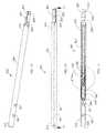
- FIG. 1illustrates a spinal distraction device having a monolithic rod and housing.
- FIG. 2illustrates the same spinal distraction device in a side view.
- FIG. 3illustrates a sectional view of the spinal distraction device of FIG. 2 along line 3 - 3 .
- FIG. 4illustrates a cross-sectional view of the spinal distraction device of FIG. 2 along line 4 - 4 .
- FIG. 5illustrates detailed view 5 of FIG. 3 .
- FIG. 6illustrates detailed view 6 of FIG. 3 .
- FIG. 7illustrates detailed view 7 of FIG. 3 .
- FIG. 8illustrates detailed view 8 of FIG. 3 .
- FIG. 9Aillustrates a distraction rod of the spinal distraction device of FIGS. 1-8 having ultrasound scattering marks.
- FIG. 9Billustrates a first alternative embodiment for ultrasound scattering.
- FIG. 9Cillustrates a second alternative embodiment for ultrasound scattering.
- FIG. 9Dillustrates a third alternative embodiment for ultrasound scattering.
- FIG. 9Eillustrates detail 9 E of the third alternative embodiment for ultrasound scattering of FIG. 9D .
- FIG. 10illustrates a device and method for measuring the amount of distraction length in a spinal distraction device, using only ultrasound imaging.
- FIG. 11is an ultrasound image of a spinal distraction device for the purpose of measuring the amount of distraction length.
- FIG. 12illustrates an intramedullary limb lengthening device having a monolithic rod and housing.
- FIG. 13illustrates the same intramedullary limb lengthening device in a side view.
- FIG. 14illustrates a sectional view of the intramedullary limb lengthening device of FIG. 13 along line 14 - 14 .
- FIG. 15Aillustrates detailed view 15 of FIG. 14 .
- FIG. 15Billustrates a sectional view of an alternative embodiment of an intramedullary limb lengthening device.
- FIG. 15Cillustrates a ring gear insert of the embodiment of FIG. 15B .
- FIG. 15Dillustrates a coupling assembly of the embodiment of FIG. 15B .
- FIG. 16illustrates an exploded view of the intramedullary limb lengthening device of FIGS. 12 through 15A .
- FIG. 17illustrates detailed view 17 of FIG. 16 .
- FIG. 18illustrates internal components of an external adjustment device for non-invasively adjusting an intramedullary limb lengthening device according to one embodiment.
- FIG. 19illustrates an external adjustment device in a configuration for adjusting an intramedullary limb lengthening device implanted within the femur.
- FIG. 20illustrates a process for assembling a spinal distraction device having improved strength.
- FIG. 21illustrates a process for assembling an intramedullary limb lengthening device having improved strength.
- FIG. 22illustrates a distraction rod and magnetic assembly being inserted into the monolithic member of the spinal distraction device.
- FIG. 23illustrates an assembly being inserted into the monolithic member of the intramedullary limb lengthening device.
- FIG. 24illustrates the assembly of FIG. 23 being pushed further into the monolithic member with a cannulated tool.
- FIGS. 1 and 2illustrate a spinal distraction device 100 comprising a distraction rod 102 and a monolithic member 104 .
- the monolithic member 104extends between a first end 110 and a second end 112 , and includes a hollow housing 106 and a solid segment 108 , as better appreciated in the sectional view of FIG. 3 .
- the monolithic member 104is formed as a unitary structure with no seams or joints.
- the distraction rod 102also includes a solid segment 114 and a hollow segment 116 .
- the distraction rod 102is a unitary structure with no seams or joints connecting various sub-components.
- Both the distraction rod 102 and the monolithic member 104may be made from a variety of biocompatible materials, including titanium, Titanium-6Al-4V, cobalt chromium alloys, and stainless steel. Because the distraction rod 102 and the monolithic member 104 are the primary load bearing members of the spinal distraction device 100 , and because neither has any external circumferential weld, the spinal distraction device 100 is capable of withstanding improved loading challenges in comparison to standard spinal distraction devices.
- the solid segment 108 of the monolithic member 104 and the solid segment 114 of the distraction rod 102have over a majority of their lengths respective diameters or thicknesses that provide a range between about 2.5 mm to about 7.5 mm, and more commonly between about 4.5 mm to about 6.35 mm.
- These solid segments 108 , 114are configured to allow coupling to pedicle screws and hooks, used for attachment to portions of the vertebrae. They may also have non-circular cross-sections, and in those cases compatible with other types of pedicle screws and hooks.
- a magnet 138is a cylindrical, radially-poled rare earth magnet, for example of neodymium-iron-boron.
- the magnet 138is enclosed and bonded within a magnet housing 140 , which in turn is rotatably contained between a thrust bearing 142 and a radial bearing 144 .
- the magnet 138may be bonded within the magnet housing 140 by epoxy.
- the magnet housing 140is coupled to a lead screw 134 by a pin 146 and a coupler 148 .
- the coupler 148is welded to an end 150 of the magnet housing 140 and both the coupler 148 and the lead screw 134 have holes through which the pin 146 is placed.
- the thrust bearing 142is held over a centering pin 154 , which fits into a cavity 158 at an end of the hollow housing 106 of the monolithic member 104 .
- a radial bearing 144is held within a spacer ring 156 .
- the distraction rod 102has a first end 118 and a second end 120 and is configured to be telescopically expandable from the hollow housing 106 of the monolithic member 104 .
- a nut 132is bonded within a cavity 152 of the hollow section 116 of the distraction rod 102 , and the lead screw 134 engages the nut 132 , so that rotation of the lead screw 134 in a first direction distracts or lengthens the distraction rod 102 and rotation of the lead screw 134 in a second, opposite direction retracts or shortens the distraction rod 102 .
- Two grooves 122run in an axial direction along the outer wall of the distraction rod 102 , from a first end 126 ( FIG. 2 ) to a second end 128 ( FIG. 6 ).
- Pins 124are spot welded or attached by other means to the wall of the hollow housing 106 of the monolithic member 104 .
- the pins 124extend radially into the grooves 122 , thus assuring that the distraction rod 102 may not rotate in relation to the monolithic member 104 , while also allowing axial extension and retraction of the distraction rod 102 in relation to the monolithic member 104 .
- a leading edge 130 of the pin 124abuts the first end 126 of the groove 122 , keeping any further retraction from happening, and avoiding any jamming between the nut 132 and the lead screw 134 .
- a leading edge 136 of the pin 124abuts a second end 128 of the groove 122 , thus assuring that the distraction rod 102 remains at least partially within the hollow housing 106 of the monolithic member 104 .
- the magnet 138comprising a north pole 160 and a south pole 162 is shown as bonded within the magnet housing 140 inside the hollow housing 106 of the monolithic member 104 .
- Two maintenance members 164are secured to the inner wall of the hollow housing 106 of the monolithic member 104 about 180° from each other along circumference.
- maintenance members 164are curved plates, preferably made from a material such as 400 series stainless steel, which has magnetic properties that allow attraction to the poles 160 , 162 of the magnet 138 when closely located. This aligns the magnet 138 , as shown, and as the subject moves, the magnet 138 is not allowed to turn, but rather stays in the desired orientation.
- the maintenance members 164may be resistance welded or adhesive or epoxy bonded to the inner wall of the monolithic member 104 . Alternatively, only one maintenance member 164 may be used, allowing attraction to either pole 160 or pole 162 of the magnet 138 , but still aligning the magnet 138 . In applications where patient movement is not significant, it may not be necessary to include any maintenance members 164 .
- the method for assembling the spinal distraction device 100is illustrated in FIG. 20 .
- the distraction rod 102 and the monolithic member 104are individually manufactured, for example by machining processes incorporating manual or automated lathes. Included within this manufacturing operation may be the forming of an axially-extending cavity within the monolithic member 104 . Post-processing may be included in this operation, for example bead blasting, passivation or anodizing.
- the distraction rod 102 and the monolithic member 104are prepared for mating. In this operation, the nut 132 is bonded into the distraction rod 102 .
- One or more o-rings 168are placed in circumferential cavities 170 of the distraction rod 102 .
- a centering pin 154is placed into the cavity 158 at the end of the hollow housing 106 of the monolithic member 104 .
- the centering pin 154may be press fit into the cavity 158 , or may be bonded with an adhesive, epoxy or other joining means.
- the thrust bearing 142is placed over the centering pin 154 .
- the distraction rod 102is coupled to the magnet 138 .
- the magnet 138is bonded into the magnet housing 140 .
- the magnet housing 140may be a two piece assembly, for example a clamshell configuration, or bookends, or a cup/cap configuration.
- the radial bearing 144is pressed over the end 150 of the magnet housing 140 and the coupler 148 is welded or bonded to the end 150 of the magnet housing 140 .
- the lead screw 134is attached to the coupler 148 by the placing the pin 146 through the holes in the coupler 148 and the lead screw 134 .
- the spacer ring 156is then slid into place over the coupler 148 and the radial bearing 144 .
- the lead screw 134is screwed into the nut 132 .
- operation 506the distraction rod 102 and magnet assembly 131 as seen in FIG.
- the magnet assembly 131is axially locked in place within the hollow housing 106 of the monolithic member 104 . More specifically, a sleeve 166 having an outer diameter close to the inner diameter of the hollow housing 106 of the monolithic member 104 is pushed into the hollow housing 106 and either press fit or bonded in place. It may also be resistance welded in place.
- the sleeve 166serves to push the assembled items into their desired axial location. When the sleeve 166 is bonded, it then holds the components in this configuration.
- the two different inner diameter portions of the spacer ring 156have the appropriate diameters and lengths so that the spacer ring 156 does not contact the magnet housing 140 .
- the distraction rodis rotationally locked in relation to the monolithic member.
- the sleeve 166is supplied with holes to match those in the wall of the hollow housing 106 through which the pins 124 are placed. Alternatively, holes may be drilled through the sleeve 166 using the holes in the hollow housing 106 as a guide.
- the o-rings 168 of the distraction rod 102serve to seal between the distraction rod 102 and the inner diameter of the sleeve 166 .
- the outer diameter of the sleeve 166is sealably attached to the inner diameter of the hollow housing 106 via the adhesive or epoxy with which it is attached. Together, these two seals protect the inner contents of the hollow housing 106 of the monolithic member 104 from body fluids.
- FIG. 9Ais a view of the distraction rod 102 of the spinal distraction device 100 of FIG. 1 , having a tapered portion 101 , and showing four landmarks 172 , 174 , 176 , 178 for scattering ultrasound.
- the landmarksmay consist of drilled indentations or partial holes, for example drilled with a small end mill. Typical hole diameter is about 1.00 mm, and typical hole depth is about 0.75 mm.
- the distraction rod 102is formed of a metal, for example Titanium 6AL-4V, and thus is very reflective of ultrasound waves, and because of its continuity and smooth surface, a consistent bright line will be seen (see white contour of distraction rod 102 image in FIG. 11 ).
- landmarks 172 , 174 , 176 , 178serve to break up this continuity, and give a small, but recognizable pattern in an ultrasound image.
- landmark 172is a single hole
- landmark 174is a (in this figure) vertically arrayed pair of holes, with a distance of 1.50 mm from center to center.
- Landmark 176consists of three vertically arrayed holes, with a center-to-center distance of adjacent holes of 1.25 mm.
- Landmark 178is two diagonally arrayed holes with a center-to-center distance of 2.75 mm.
- FIG. 10illustrates the spinal distraction device 100 implanted in a subject, and attached to four vertebrae 184 using pedicle screws 182 .
- the spinal distraction device 100has been lengthened a cumulative total amount of 17.6 mm, and landmarks 172 , 174 have been extended from the hollow housing 106 of the monolithic member 104 , while landmarks 176 , 178 are still inside.
- the nose 188 of an ultrasound probe 186is coated with an ultrasound gel and pressed over the skin 190 .
- the ultrasound probe 186 illustratedhas a linear array transducer 192 having a span of 40 mm, though probes are also available with spans of up to 64 mm, such as the General Electric L764.
- a transducercapable of being run at five to ten MegaHertz (5.0-10.0 MHz) is appropriate for the spinal distraction application, because it will be able to image the spinal distraction device 100 at its typical range of depths, based on patient tissue thickness.
- the ultrasound probe 186is centered over the region of interest (ROI), and adjusted until an image such as that in FIG. 11 can be visualized.
- the region of interest in FIG. 10includes the extended landmarks 172 , 174 and the first end 110 of the monolithic member 104 .
- a cable 202transfers signals back and forth between the linear array transducer 192 and an ultrasound unit 200 . Signals are processed in a processor 206 , and can be stored in a memory 208 .
- An interface (keyboard, touch screen, etc.) 210can be manipulated by the user to operate the ultrasound unit 200 .
- the resulting imagemay be visualized on a display 204 .
- Ultrasound waves 212are transmitted to the spinal distraction device 100 and reflected waves 214 are received.
- an ultrasound scan 216was performed using a 40 mm linear array transducer at 8.0 MHz. Skin 190 , fat 194 , and muscle 196 covered by fascia 218 can be clearly seen, as can the surface of the distraction rod 102 , seen in bright white, and the first end 110 of the monolithic member 104 . Beneath these features is an area of ultrasonic shadowing 220 , due to lack of penetration of the ultrasound wave past the highly reflective titanium of the distraction rod 102 and the monolithic member 104 . A first landmark 222 and second landmark 224 are also visible on the ultrasound scan 216 .
- the distraction rod 102 and the monolithic member 104move relative to each other when the spinal distraction device 100 is lengthened or shortened, a measurement should be taken between a landmark on the distraction rod 102 and a landmark on the monolithic member 104 .
- the preferred landmark on the monolithic member 104is the first end 110 , because it is easy to appreciate the drop off in diameter from it to the distraction rod 102 that is seen extending from the monolithic member 104 .
- the userplaced a first cursor 226 along the x-axis in line with the first end 110 , but on the y-axis at the level of the surface of the distraction rod 102 .
- Varying the y-axis locationis not necessary in ultrasound units that give an x distance, y distance and a hypotenuse.
- a second cursor 228was then moved to the desired landmark on the distraction rod 102 , for example landmark 222 or landmark 224 .
- Many ultrasound unitsallow for accurate on-screen caliper measurements, but alternatively, the distance between first landmark 222 and second landmark 224 , a known, controlled distance, may be used for accurate scaling.
- the holes depicted in FIG. 9Amay be left open, or they may be filled, for example with epoxy.
- the epoxymay be doped with ceramic particles, in order to scatter the ultrasound in a still different manner.
- FIGS. 9B through 9Dseveral alternative embodiments for scattering ultrasound are presented in FIGS. 9B through 9D , particularly depicting tapered portion 101 of distraction rod 102 .
- the tapered portion 101includes a taper 107 that extends between small diameter segment 103 and large diameter segment 105 .
- Large diameter segment 105has a typical diameter of about 6.35 mm
- small diameter segment 103has a typical diameter of about 2.5 to 6.0 mm, or more particularly 4.5 mm to 6.0 mm.
- FIG. 9BBetween the small diameter segment 103 and that taper 107 is a radiused transition.
- a sharp transition 111is formed in the distraction rod 102 at the tapered portion 101 .
- This sharp transition 111provides a highly defined point in the ultrasound image for making a precision axial measurement.
- FIG. 9Can embodiment is depicted which features a short ridge 113 extending around the distraction rod 102 .
- the ridge 113also provides a highly defined point for resolving in an ultrasound image.
- FIG. 9Ddepicts an embodiment having an ultrasound focusing feature 115 in place of the ridge 113 of FIG. 9C .
- the ultrasound focusing feature 115as seen in more detail in FIG.
- 9Eincludes a concave radius 117 extending around the distraction rod 102 .
- Ultrasoundreflects at a range of angles along different axial points on the concave radius 117 , and the reflected ultrasound from these various reflections meets at a focal point 119 , thus creating a recognizable image.
- FIGS. 12 and 13illustrate an intramedullary limb lengthening device 300 comprising a distraction rod 302 and a monolithic member 304 .
- the monolithic member 304extends between a first end 310 and a second end 312 , as better appreciated in the sectional view of FIG. 14 .
- the monolithic member 304is formed as a unitary structure with no seams or joints.
- the distraction rod 302has a first end 318 and a second end 320 , and is configured to be telescopically extendable and retractable within the monolithic member 304 .
- the distraction rod 302is a unitary structure with no seams or joints connecting various sub-components.
- Both the distraction rod 302 and the monolithic member 304may be made from a variety of biocompatible materials, including titanium, for example Titanium-6AL-4V, cobalt chromium alloys, and stainless steel. Because the distraction rod 302 and the monolithic member 304 are the primary load bearing members of the intramedullary limb lengthening device 300 , and because neither has any external circumferential weld, the intramedullary limb lengthening device 300 is capable of withstanding improved loading challenges in comparison to standard intramedullary limb lengthening devices.
- the monolithic member 304contains two transverse holes 301 for passing bone screws, with which to attach the intramedullary limb lengthening device 300 to the bone.
- the distraction rod 302contains three transverse holes 303 , also for the passing of bone screws.
- a coupling feature 323provides an interface to releasably engage with an insertion instrument, such as a drill guide.
- the drill guidemay include a male thread and the coupling feature 323 may be provided with a complementary female thread.
- the intramedullary limb lengthening device 300comprises a magnet 338 which is bonded within a magnet housing 340 and configured for rotation between a radial bearing 344 and a thrust bearing 342 . Between the thrust bearing 342 and the magnet housing 340 are three planetary gear stages 305 , 307 , 309 , as seen in FIG. 15A .
- the planetary gear stages 305 , 307 , 309each comprise a sun gear 311 A, 311 B, 311 C and three planetary gears 313 , which are rotatably held within a frame 315 by pins 317 .
- the sun gear 311is either a part of the magnet housing 340 , as in the case of the sun gear 311 A of planetary gear stage 305 , or a part of the frame 315 , as in sun gear 311 B or gear stage 307 and sun gear 311 C of gear stage 309 .
- the rotation of the sun gear 311causes the planetary gears 313 to rotate and track along inner teeth 321 of a ring gear insert 319 .
- Each gear stage 305 , 307 , 309has a gear reduction of 4:1, with a total gear reduction of 64:1.
- the frame 315 of the final gear stage 309passes through the thrust bearing 342 and is attached to a lead screw coupler 366 such that rotation of the frame 315 of the final gear stage 309 causes one-to-one rotation of the lead screw coupler 366 .
- the lead screw coupler 366 and a lead screw 358each contain transverse holes through which a locking pin 368 is placed, thus rotationally coupling the lead screw 358 to the final gear stage 309 .
- a locking pin retainer 350is slid over and tack welded to the lead screw coupler 366 to radially maintain the locking pin 368 in place.
- the distraction rod 302has an internally threaded end 363 , into which external threads 365 of a nut 360 are threaded and bonded, for example with epoxy.
- the nut 360has internal threads 367 which are configured to threadably engage with external threads 325 of the lead screw 358 , thereby allowing rotation of the lead screw 358 to distract the distraction rod 302 in relation to the monolithic member 304 .
- Rotation of the magnet 338 and the magnet housing 340causes rotation of the lead screw at 1/64 the rotational speed, but with significantly increased torque (64 times, minus frictional losses), and thus an amplified distraction force.
- O-rings 362are placed in ring grooves 388 on exterior of the distraction rod 302 and create a dynamic seal between the monolithic member 304 and the distraction rod 302 , thus protecting the internal contents from body fluids.
- a split washer stop 364located between the distraction rod 302 and the lead screw coupler 366 , guards against jamming that would otherwise be caused as the distraction rod 302 approaches the lead screw coupler 366 , for example if intramedullary limb lengthening device 300 is fully retracted with a high torque applied by an external moving magnetic field.
- a maintenance member 346comprising a curved plate made from 400 series stainless steel, is bonded within the inner wall of the monolithic member 304 by epoxy, adhesive, resistance welding or other suitable process.
- the maintenance member 346attracts a pole of the magnet 338 , thus keeping the limb lengthening device 300 from being accidentally adjusted by movements of the patient.
- a strong moving magnetic fieldsuch as that applied by magnetic adjustment devices known in the art, is capable of overcoming the attraction of the magnet 338 to the maintenance member 346 in order to rotate the magnet 338 and adjust the length of the intramedullary limb lengthening device 300 .
- Maintenance memberhas a thickness of approximately 0.015 inches and spans a circumferential arc of less than 180°. An exemplary arc is 99°.
- the method for assembling the intramedullary limb lengthening device 300is illustrated in FIG. 21 .
- These assembly operations and the design of the internal componentsmake it possible to incorporate the monolithic member 304 into the design of the intramedullary limb lengthening device 300 .
- the distraction rod 302 and the monolithic member 304are individually manufactured, for example by machining processes incorporating manual or automated lathes. Included within this manufacturing operation may be the forming of an axially-extending cavity within the monolithic member 304 . Post-processing may be included in this operation, for example bead blasting, passivation or anodizing.
- the distraction rod 302 and the monolithic member 304are prepared for mating.
- the nut 360is bonded into the distraction rod 302 and the o-rings 362 are placed into the ring grooves 388 as described.
- the maintenance member 346is bonded to the monolithic member 304 .
- the magnet 338is placed into the cavity 390 of the monolithic member 304 .
- the magnet 338 and the magnet housing 340are bonded together, and then assembled with the radial bearing 344 into the monolithic member 304 (see FIG. 14 ).
- the longitudinal depth of the cavity 390 of the monolithic member 304is measured, and, if necessary, one or more shims may be placed before the radial bearing 344 so that the resultant axial play in the assembled components is not so low as to cause binding, yet not so high as to risk disassembly.
- the lead screw 358is prepared for coupling to the magnet 338 that is in the cavity 390 of the monolithic member 304 .
- the ring gear insert 319is slid into the cavity 390 of the monolithic member 304 until it abuts a ledge 392 .
- First and second planetary gear stages 305 , 307are then placed into assembly as seen in FIG. 15A .
- the locking pin retainer 350is preloaded over the lead screw coupler 366 prior to welding the lead screw coupler 366 to the final planetary gear stage 309 , and is then slid in place over the locking pin 368 after the locking pin 368 is placed.
- Final planetary gear stage 309is inserted through the thrust bearing 342 and is welded to the lead screw coupler 366 , allowing for some axial play of the thrust bearing 342 .
- the split washer stop 364is then placed onto the lead screw 358 .
- Thrust bearing retainers 354 , 356are two matching pieces which form a cylindrical clamshell around the thrust bearing 342 and the lead screw coupler 366 .
- the internal diameter of the monolithic member 304is tinned with solder, as are the outer half diameter surfaces of each of the thrust bearing retainers 354 , 356 .
- the thrust bearing retainers 354 , 356are then clamped over an assembly 327 (illustrated in FIG.
- the cannulated tool 329has a chamfered end 331 which pushes against a matching chamfer 352 in each of the thrust bearing retainers 354 , 356 , thus forcing them outward against the inner diameter of the monolithic member 304 .
- the sun gear 311 C of the final planetary gear stage 309engages with the planet gears 313 of the final planetary gear stage 309 and then chamfered edges 394 of the thrust bearing retainers 354 , 356 are pushed against a chamfer 348 of the ring gear insert 319 with a pre-load force.
- the thrust bearing 342 and the magnet 338are axially retained.
- the thrust bearing retainers 354 , 356are soldered to the monolithic member 304 at the tinned portions, thus maintaining the pre-load force in place. This may be accomplished using induction heating.
- the ring gear insert 319may have a keyed feature that fits into a corresponding keyed feature in the monolithic member 304 , in order to stop the ring gear insert 319 from being able to turn in relation to the monolithic member 304 , in case the friction on the ends of the ring gear insert 319 is not sufficient to hold it static.
- the distraction rod 302is engaged with the lead screw 358 .
- an assembly toolconsisting of a high speed rotating magnet is used to make the magnet 338 and thus the lead screw 358 rotate and the distraction rod 302 is inserted into the monolithic member 304 while the lead screw 358 engages and displaces in relation to the nut 360 of the distraction rod 302 .
- the distraction rod 302is still free to rotate in relation to the monolithic member 304 .
- this final portion of the assembly processis described in relation to FIGS.
- the distraction rod 302is rotationally locked in relation to the monolithic member 304 .
- an anti-rotation ring 370is placed over the distraction rod 302 by engaging protrusions 374 , one on each side, into grooves 372 extending along the distraction rod 302 and then by sliding the anti-rotation ring 370 up to a tapered inner edge 376 of the monolithic member 304 .
- the anti-rotation ring 370 and the distraction rod 302are then rotated until guide fins 382 can be inserted into guide cuts 380 in end of the monolithic member 304 .
- the anti-rotation ring 370is now axially snapped into the monolithic member 304 as a flat edge 384 of the anti-rotation ring 370 is trapped by an undercut 378 .
- the undercut 378has a minimum diameter which is less than the outer diameter of the flat edge 384 of the anti-rotation ring 370 , and is temporarily forced open during the snapping process.
- the anti-rotation ring 370 , the monolithic member 304 and the distraction rod 302are all held rotationally static in relation to each other.
- the ends 386 of grooves 372abut the protrusions 374 , and thus the distraction rod 302 is kept from falling out of the monolithic member 304 .
- FIG. 15BAn alternative embodiment of the intramedullary limb lengthening device 300 of FIGS. 12-15A is shown in a sectional view in FIG. 15B .
- Much of this embodimentis identical to the embodiment of FIGS. 12-15A , however the differences are hereby described.
- the embodimentdoes not have thrust bearing retainers 354 , 356 , but instead incorporates a thrust bearing ferrule 335 having an external tapered end 347 .
- a thrust bearing retainer 337 , a locking pin retainer 341 and the thrust bearing ferrule 335are placed over the thrust bearing 342 and a lead screw coupler 339 , and the final planetary gear stage 309 is inserted through the thrust bearing 342 and is welded to the lead screw coupler 339 .
- FIG. 15BAn alternative embodiment of the intramedullary limb lengthening device 300 of FIGS. 12-15A is shown in a sectional view in FIG. 15B .
- Much of this embodimentis identical to the embodiment of FIGS. 12-15
- the locking pin retainer 341has a relief 361 to allow the passage of the locking pin 368 .
- the locking pin retainer 341is rotated so that the relief 361 is no longer directly over the locking pin 368 and the locking pin retainer 341 is tack welded or secured by other methods to the lead screw coupler 339 , thus retaining the locking pin 368 .
- These assembled componentsare then inserted into the cavity 390 of the monolithic member 304 , where the final planetary gear stage 309 is coupled to the other planetary gear stages 305 , 307 and the magnet 338 .
- a ring gear insert 333( FIG. 15C ) has an indentation 351 on each side.
- a tab 349 on each side of the thrust bearing ferrule 335inserts into each indentation 351 , in order to inhibit rotation of the ring gear insert 333 in relation to the monolithic member 304 , once the thrust bearing ferrule 335 is engaged into the monolithic member 304 .
- the monolithic member 304contains internal threading 343 . The engagement of the thrust bearing ferrule 335 is achieved by tightening external threading 345 of the thrust bearing retainer 337 into the internal threading 343 of the monolithic member 304 .
- a tool(not shown) is engaged into cut outs 357 on each side of the thrust bearing retainer 337 and is used to screw the thrust bearing retainer 337 into the internal threading 343 of the monolithic member 304 . As shown in FIG. 15B , this wedges an internal taper 353 of the thrust bearing retainer 337 against the external tapered end 347 of the thrust bearing ferrule 335 , allowing the thrust bearing ferrule 335 to apply a controlled load on the ring gear insert 333 , locking the ring gear insert 333 axially and rotationally in relation to the monolithic member 304 .
- the thrust bearing retainer 337contains an axial split on the opposite side (not shown).
- the split in the thrust bearing retainer 337allows the outer diameter of the thrust bearing retainer 337 to be slightly reduced (by compression) while it is inserted into the monolithic member 304 , prior to being threaded, so that the internal portion of the monolithic member 304 is not scratched during insertion.
- a ledge 355is visible on the lead screw coupler 339 in FIG. 15D . As noted earlier, the split washer stop 364 butts up against this ledge 355 to prohibit jamming when the distraction rod 302 is retracted completely.
- FIGS. 18 and 19illustrate an external adjustment device 478 configured for applying a moving magnetic field to allow for non-invasive adjustment of the intramedullary limb lengthening device 300 by turning the magnet 338 within the intramedullary limb lengthening device 300 .
- FIG. 18illustrates the internal components of the external adjustment device 478 , and for clear reference, shows the magnet 338 of the intramedullary limb lengthening device 300 , without the rest of the assembly.
- the internal working components of the external adjustment device 478may, in certain embodiments, be similar to that described in U.S. Patent Application Publication No. 2012/0004494, which is incorporated by reference herein.
- a motor 480 with a gear box 482outputs to a motor gear 484 .
- the motor gear 484engages and turns a central (idler) gear 486 , which has the appropriate number of teeth to turn first and second magnet gears 488 , 490 at identical rotational speeds.
- First and second magnets 492 , 494turn in unison with the first and second magnet gears 488 , 490 , respectively.
- Each magnet 492 , 494is held within a respective magnet cup 496 (shown partially).
- An exemplary rotational speedis 60 RPM or less. This speed range may be desired in order to limit the amount of current density induced in the body tissue and fluids, to meet international guidelines or standards. As seen in FIG.
- the south pole 498 of the first magnet 492is oriented the same as the north pole 404 of the second magnet 494 , and likewise, the first magnet 492 has its north pole 400 oriented the same as the south pole 402 of the second magnet 494 .
- these two magnets 492 , 494turn synchronously together, they apply a complementary and additive moving magnetic field to the radially-poled, magnet 338 , having a north pole 406 and a south pole 408 .
- Magnets having multiple north poles (for example, two) and multiple south poles (for example, two)are also contemplated in each of the devices.
- the magnetic couplingcauses the magnet 338 to turn in a second, opposite rotational direction 412 (e.g., clockwise).
- the rotational direction of the motor 480is controlled by buttons 414 , 416 .
- One or more circuit boards 418contain control circuitry for both sensing rotation of the magnets 492 , 494 and controlling the rotation of the magnets 492 , 494 .
- FIG. 19shows the external adjustment device 478 for use with an intramedullary limb lengthening device 300 placed in the femur.
- the external adjustment device 478has a first handle 424 attached to a housing 444 for carrying or for steadying the external adjustment device 478 , for example, steadying it against an upper leg 420 , as in FIG. 19 , or against a lower leg 422 in the case that the intramedullary limb lengthening device 300 is implanted in the tibia.
- An adjustable handle 426is rotationally attached to the external adjustment device 478 at pivot points 428 , 430 .
- the pivot points 428 , 430have easily lockable/unlockable mechanisms, such as a spring loaded brake, ratchet or tightening screw, so that a desired angulation of the adjustable handle 426 in relation to the housing 444 can be adjusted and locked in orientation.
- the adjustable handle 426is capable of being placed in multiple positions. In FIG. 19 , adjustable handle 426 is set so that the apex 432 of loop 434 rests against housing end 436 . In this position, patient 438 is able to hold onto one or both of grips 440 , 442 while the adjustment is taking place. Patient is able to clearly view a control panel 446 including a display 448 . In a different configuration from the two directional buttons 414 , 416 in FIG.
- the control panel 446includes a start button 450 , a stop button 452 and a mode button 454 .
- Control circuitry contained on circuit boards 418may be used by the surgeon to store important information related to the specific aspects of each particular patient. For example, in some patients an implant may be placed antegrade into the tibia. In other patients the implant may be placed either antegrade or retrograde into the femur.
- the external adjustment device 478can be configured to direct the magnets 492 , 494 to turn in the correct direction automatically, while the patient need only place the external adjustment device 478 at the desired position, and push the start button 450 .
- the information of the maximum allowable distraction length per day and per distraction sessioncan also be input and stored by the surgeon for safety purposes. These may also be added via an SD card or USB device, or by wireless input.
- An additional featureis a camera at the portion of the external adjustment device 478 that is placed over the skin.
- the cameramay be located between the first magnet 492 and the second magnet 494 .
- the skin directly over the implanted magnet 338may be marked with indelible ink.
- a live image from the camerais then displayed on the display 448 of the control panel 446 , allowing the user to place the first and second magnets 492 , 494 directly over the area marked on the skin.
- Crosshairscan be overlayed on the display 448 over the live image, allowing the user to align the mark on the skin between the crosshairs, and thus optimally place the external adjustment device 478 .
- load-bearing orthopedic devicescan be constructed which, by incorporating a monolithic member 104 , 304 having a unitary structure with no seams or joints, have improved strength over prior art devices having welded joints.
- Four point bend testing of monolithic members 304 constructed in accordance with the methods described hereinshowed that a strength improvement of 38% was achieved as compared to data obtained on elongate members which incorporated a housing having a laser weld.
- the embodiments for the spinal distraction device 100 and the intramedullary limb lengthening device 300 described hereinhave features which inhibit rotation between the distraction rod 102 , 302 and the monolithic member 104 , 304 , maintain the magnet 138 , 338 in its axial position in relation to the monolithic member 104 , 304 , and keep the distraction rod 102 , 302 from falling out of the monolithic member 104 , 304 by providing a stopping mechanism at full extension. All of these features were not achievable in prior devices without resorting to welds which decreased the overall strength.
- the magnets in the devicesmay be replaced by any type of drive member, for example motors or shape memory mechanisms. They may also be replaced by a subcutaneous lever that allows the device to be non-invasively adjusted.
- the inventiontherefore, should not be limited, except to the following claims, and their equivalents.
Landscapes
- Health & Medical Sciences (AREA)
- Orthopedic Medicine & Surgery (AREA)
- Life Sciences & Earth Sciences (AREA)
- Surgery (AREA)
- Neurology (AREA)
- Molecular Biology (AREA)
- General Health & Medical Sciences (AREA)
- Biomedical Technology (AREA)
- Heart & Thoracic Surgery (AREA)
- Medical Informatics (AREA)
- Nuclear Medicine, Radiotherapy & Molecular Imaging (AREA)
- Animal Behavior & Ethology (AREA)
- Engineering & Computer Science (AREA)
- Public Health (AREA)
- Veterinary Medicine (AREA)
- Physics & Mathematics (AREA)
- Electromagnetism (AREA)
- Oral & Maxillofacial Surgery (AREA)
- Pathology (AREA)
- Surgical Instruments (AREA)
Abstract
Description
Claims (20)
Priority Applications (4)
| Application Number | Priority Date | Filing Date | Title |
|---|---|---|---|
| US13/791,430US9179938B2 (en) | 2013-03-08 | 2013-03-08 | Distraction devices and method of assembling the same |
| US14/863,019US10463406B2 (en) | 2013-03-08 | 2015-09-23 | Systems and methods for ultrasonic detection of device distraction |
| US16/581,011US11344342B2 (en) | 2013-03-08 | 2019-09-24 | Systems and methods for ultrasonic detection of device distraction |
| US17/730,530US11857226B2 (en) | 2013-03-08 | 2022-04-27 | Systems and methods for ultrasonic detection of device distraction |
Applications Claiming Priority (1)
| Application Number | Priority Date | Filing Date | Title |
|---|---|---|---|
| US13/791,430US9179938B2 (en) | 2013-03-08 | 2013-03-08 | Distraction devices and method of assembling the same |
Related Child Applications (1)
| Application Number | Title | Priority Date | Filing Date |
|---|---|---|---|
| US14/863,019ContinuationUS10463406B2 (en) | 2013-03-08 | 2015-09-23 | Systems and methods for ultrasonic detection of device distraction |
Publications (2)
| Publication Number | Publication Date |
|---|---|
| US20140250674A1 US20140250674A1 (en) | 2014-09-11 |
| US9179938B2true US9179938B2 (en) | 2015-11-10 |
Family
ID=51485985
Family Applications (4)
| Application Number | Title | Priority Date | Filing Date |
|---|---|---|---|
| US13/791,430Active2033-09-07US9179938B2 (en) | 2013-03-08 | 2013-03-08 | Distraction devices and method of assembling the same |
| US14/863,019Active2036-02-19US10463406B2 (en) | 2013-03-08 | 2015-09-23 | Systems and methods for ultrasonic detection of device distraction |
| US16/581,011Active2033-12-30US11344342B2 (en) | 2013-03-08 | 2019-09-24 | Systems and methods for ultrasonic detection of device distraction |
| US17/730,530Active2033-04-27US11857226B2 (en) | 2013-03-08 | 2022-04-27 | Systems and methods for ultrasonic detection of device distraction |
Family Applications After (3)
| Application Number | Title | Priority Date | Filing Date |
|---|---|---|---|
| US14/863,019Active2036-02-19US10463406B2 (en) | 2013-03-08 | 2015-09-23 | Systems and methods for ultrasonic detection of device distraction |
| US16/581,011Active2033-12-30US11344342B2 (en) | 2013-03-08 | 2019-09-24 | Systems and methods for ultrasonic detection of device distraction |
| US17/730,530Active2033-04-27US11857226B2 (en) | 2013-03-08 | 2022-04-27 | Systems and methods for ultrasonic detection of device distraction |
Country Status (1)
| Country | Link |
|---|---|
| US (4) | US9179938B2 (en) |
Cited By (19)
| Publication number | Priority date | Publication date | Assignee | Title |
|---|---|---|---|---|
| US20160058483A1 (en)* | 2014-09-01 | 2016-03-03 | Wittenstein Ag | Medullary pin |
| US20160367297A1 (en)* | 2015-06-16 | 2016-12-22 | Wittenstein Ag | Mechanotronic implant |
| TWI609685B (en)* | 2016-08-19 | 2018-01-01 | Hong Zheng Xiong | Electric crutch with length locking mechanism |
| US20180317980A1 (en)* | 2008-10-31 | 2018-11-08 | Peter Forsell | Device and method for bone adjustment with anchoring function |
| US10368918B2 (en) | 2011-03-01 | 2019-08-06 | Nuvasive, Inc. | Posterior cervical fixation system |
| US10456172B2 (en) | 2016-02-12 | 2019-10-29 | Nuvasive, Inc. | Magnetically actuateable rod insertion for minimally invasive surgery |
| US10463406B2 (en)* | 2013-03-08 | 2019-11-05 | Nuvasive Specialized Orthopedics, Inc. | Systems and methods for ultrasonic detection of device distraction |
| US10610261B2 (en) | 2016-02-12 | 2020-04-07 | Nuvasive, Inc. | Post-operatively adjustable angled rod |
| WO2020152171A2 (en) | 2019-01-24 | 2020-07-30 | Augustin Betz | Curved intramedullary nail |
| WO2020187463A1 (en) | 2019-03-15 | 2020-09-24 | Augustin Betz | Connecting device for connecting two bone parts |
| US10905559B2 (en) | 2018-10-30 | 2021-02-02 | Magnetic Joints LLC | Magnetic locking mechanism (MLM) for joint arthroplasty |
| WO2022015898A1 (en)* | 2020-07-17 | 2022-01-20 | Nuvasive Specialized Orthopedics, Inc. | Extramedullary device and system |
| US11278330B2 (en)* | 2017-02-02 | 2022-03-22 | Smith & Nephew, Inc. | Implantable bone adjustment devices |
| US11291478B2 (en) | 2016-02-12 | 2022-04-05 | Nuvasive, Inc. | Post-operatively adjustable spinal fixation devices |
| US11446063B2 (en) | 2016-02-12 | 2022-09-20 | Nuvasive, Inc. | Post-operatively adjustable angled rod |
| DE102021127020A1 (en) | 2021-10-19 | 2023-04-20 | Augustin Betz | Curved intramedullary nail |
| US11766278B2 (en) | 2017-11-30 | 2023-09-26 | Nuvasive, Inc. | Implantable distraction device |
| EP4275631A2 (en) | 2015-12-10 | 2023-11-15 | NuVasive Specialized Orthopedics, Inc. | External adjustment device for distraction device |
| US12433649B2 (en) | 2019-02-13 | 2025-10-07 | The Trustees Of The University Of Pennsylvania | Systems and methods for a smart, implantable cranio-maxillo-facial distractor |
Families Citing this family (21)
| Publication number | Priority date | Publication date | Assignee | Title |
|---|---|---|---|---|
| WO2014145470A2 (en)* | 2013-03-15 | 2014-09-18 | Agarwal Anand K | Spinal rods formed from polymer and hybrid materials and growth rod distraction system including same |
| CN105916458B (en)* | 2013-06-24 | 2019-09-27 | 托莱多大学 | Bioactive Fusion Devices |
| US9931138B2 (en)* | 2014-10-15 | 2018-04-03 | Globus Medical, Inc. | Orthopedic extendable rods |
| ES2908064T3 (en)* | 2014-12-26 | 2022-04-27 | Nuvasive Specialized Orthopedics Inc | distraction systems |
| US10238427B2 (en)* | 2015-02-19 | 2019-03-26 | Nuvasive Specialized Orthopedics, Inc. | Systems and methods for vertebral adjustment |
| US11006977B2 (en)* | 2015-10-05 | 2021-05-18 | Global Medical Inc | Growing rod for treating spinal deformities and method for using same |
| BR112018007347A2 (en)* | 2015-10-16 | 2018-10-23 | Nuvasive Specialized Orthopedics, Inc. | adjustable devices for the treatment of knee arthritis |
| BR112018015504A2 (en)* | 2016-01-28 | 2018-12-18 | Nuvasive Specialized Orthopedics, Inc. | bone transport systems |
| US20170293500A1 (en)* | 2016-04-06 | 2017-10-12 | Affirmed Networks Communications Technologies, Inc. | Method for optimal vm selection for multi data center virtual network function deployment |
| FI20165445A (en) | 2016-05-27 | 2017-11-28 | Synoste Oy | Intracorporeal telescopic osteodistraction device, extracorporeal force generating device, bone extension method and bone extension arrangement |
| WO2018102101A2 (en)* | 2016-11-09 | 2018-06-07 | Children's Hospital Medical Center Of Akron | Distraction osteogenesis system |
| CA3112474A1 (en) | 2018-10-04 | 2020-04-09 | Polyvalor, Limited Partnership | Internal fixator apparatus for distraction osteogenesis |
| US12161369B2 (en) | 2018-11-26 | 2024-12-10 | Globus Medical, Inc. | Intra-corporal telescopic osteodistraction device, an extra corporal force producing device, a method for bone lengthening and a bone lengthening arrangement |
| TR201907277A2 (en)* | 2019-05-14 | 2020-11-23 | Univ Yildiz Teknik | Tumor prosthesis autonomous control and extension system. |
| WO2021045946A1 (en)* | 2019-09-03 | 2021-03-11 | Nuvasive Specialized Orthopedics, Inc. | Acoustic reporting for dynamic implants |
| US20220021467A1 (en)* | 2020-07-15 | 2022-01-20 | Nuvasive Specialized Orthopedics, Inc. | Ultrasonic Communication Phased Array |
| US20220015811A1 (en)* | 2020-07-15 | 2022-01-20 | Nuvasive Specialized Orthopedics, Inc. | Ultrasonic communication in adjustable implants |
| EP4380480A1 (en)* | 2021-08-03 | 2024-06-12 | NuVasive Specialized Orthopedics, Inc. | Adjustable implant |
| US12232790B2 (en) | 2022-12-30 | 2025-02-25 | IvyTech Design LLC | Adjustable angle orthopedic distractor, compressor, and distractor-compressor |
| WO2024238636A1 (en)* | 2023-05-15 | 2024-11-21 | Cornell University | Magnetically actuated cranial bioresorbable distraction system |
| USD1071009S1 (en)* | 2023-06-27 | 2025-04-15 | Blitz Grenade Inc. | Distraction device |
Citations (116)
| Publication number | Priority date | Publication date | Assignee | Title |
|---|---|---|---|---|
| US2702031A (en)* | 1953-09-25 | 1955-02-15 | Wenger Herman Leslie | Method and apparatus for treatment of scoliosis |
| WO1987007134A1 (en)* | 1986-05-30 | 1987-12-03 | John Bumpus | Distraction rods |
| US5575790A (en) | 1995-03-28 | 1996-11-19 | Rensselaer Polytechnic Institute | Shape memory alloy internal linear actuator for use in orthopedic correction |
| US5704939A (en) | 1996-04-09 | 1998-01-06 | Justin; Daniel F. | Intramedullary skeletal distractor and method |
| US6033412A (en) | 1997-04-03 | 2000-03-07 | Losken; H. Wolfgang | Automated implantable bone distractor for incremental bone adjustment |
| US6336929B1 (en)* | 1998-01-05 | 2002-01-08 | Orthodyne, Inc. | Intramedullary skeletal distractor and method |
| US6375682B1 (en) | 2001-08-06 | 2002-04-23 | Lewis W. Fleischmann | Collapsible, rotatable and expandable spinal hydraulic prosthetic device |
| US6417750B1 (en) | 1994-05-02 | 2002-07-09 | Srs Medical Systems, Inc. | Magnetically-coupled implantable medical devices |
| US6416516B1 (en) | 1999-02-16 | 2002-07-09 | Wittenstein Gmbh & Co. Kg | Active intramedullary nail for the distraction of bone parts |
| US20030149487A1 (en)* | 2002-02-04 | 2003-08-07 | Doubler Robert L. | Skeletal fixation device with linear connection |
| US20040023623A1 (en) | 2000-11-09 | 2004-02-05 | Roman Stauch | Device for controlling, regulating and/or putting an active implant into operation |
| US6706042B2 (en) | 2001-03-16 | 2004-03-16 | Finsbury (Development) Limited | Tissue distractor |
| US6730087B1 (en) | 1998-07-02 | 2004-05-04 | Michael Butsch | Bone distraction device |
| US6849076B2 (en) | 2000-04-13 | 2005-02-01 | University College London | Surgical distraction device |
| US20050090823A1 (en) | 2003-10-28 | 2005-04-28 | Bartimus Christopher S. | Posterior fixation system |
| US20050159754A1 (en) | 2004-01-21 | 2005-07-21 | Odrich Ronald B. | Periosteal distraction bone growth |
| US20050234448A1 (en) | 2004-03-19 | 2005-10-20 | Mccarthy James | Implantable bone-lengthening device |
| US20050246034A1 (en) | 2002-08-30 | 2005-11-03 | Arnaud Soubeiran | Implantable mechanical device with adjustable geometry |
| US20050261779A1 (en)* | 2003-11-17 | 2005-11-24 | Meyer Rudolf X | Expansible rod-type prosthesis and external magnetic apparatus |
| US20060004459A1 (en)* | 2004-06-30 | 2006-01-05 | Hazebrouck Stephen A | Adjustable orthopaedic prosthesis and associated method |
| US20060009767A1 (en)* | 2004-07-02 | 2006-01-12 | Kiester P D | Expandable rod system to treat scoliosis and method of using the same |
| US20060047282A1 (en)* | 2004-08-30 | 2006-03-02 | Vermillion Technologies, Llc | Implant for correction of spinal deformity |
| US7063706B2 (en) | 2001-11-19 | 2006-06-20 | Wittenstein Ag | Distraction device |
| US20060204154A1 (en)* | 2005-03-14 | 2006-09-14 | Ward Daniel N | Bearing system for a turbocharger |
| WO2006103071A1 (en) | 2005-03-31 | 2006-10-05 | Stryker Trauma Gmbh | A hybrid electromagnetic-acoustic distal targeting system |
| US20060235424A1 (en) | 2005-04-01 | 2006-10-19 | Foster-Miller, Inc. | Implantable bone distraction device and method |
| US7135022B2 (en) | 2001-05-23 | 2006-11-14 | Orthogon 2003 Ltd. | Magnetically-actuable intramedullary device |
| US20060293683A1 (en) | 2003-04-16 | 2006-12-28 | Roman Stauch | Device for lengthening bones or bone parts |
| US20070010814A1 (en) | 2003-08-28 | 2007-01-11 | Roman Stauch | Device for extending bones |
| US20070264605A1 (en) | 2005-05-19 | 2007-11-15 | Theodore Belfor | System and method to bioengineer facial form in adults |
| US20070270803A1 (en) | 2006-04-06 | 2007-11-22 | Lukas Giger | Remotely Adjustable Tissue Displacement Device |
| US20070276378A1 (en) | 2004-09-29 | 2007-11-29 | The Regents Of The University Of California | Apparatus and methods for magnetic alteration of anatomical features |
| WO2008003952A1 (en) | 2006-07-04 | 2008-01-10 | The University Of Birmingham | Distraction device |
| US7357635B2 (en) | 2004-05-19 | 2008-04-15 | Orthovisage Inc. | System and method to bioengineer facial form in adults |
| US20080161933A1 (en) | 2005-09-26 | 2008-07-03 | Innvotec Surgical, Inc. | Selectively expanding spine cage, hydraulically controllable in three dimensions for vertebral body replacement |
| US20080167685A1 (en) | 2007-01-05 | 2008-07-10 | Warsaw Orthopedic, Inc. | System and Method For Percutanously Curing An Implantable Device |
| US20080228186A1 (en) | 2005-04-01 | 2008-09-18 | The Regents Of The University Of Colorado | Graft Fixation Device |
| US20080255615A1 (en) | 2007-03-27 | 2008-10-16 | Warsaw Orthopedic, Inc. | Treatments for Correcting Spinal Deformities |
| US7458981B2 (en) | 2004-03-09 | 2008-12-02 | The Board Of Trustees Of The Leland Stanford Junior University | Spinal implant and method for restricting spinal flexion |
| US20090076597A1 (en) | 2007-09-19 | 2009-03-19 | Jonathan Micheal Dahlgren | System for mechanical adjustment of medical implants |
| US20090093890A1 (en) | 2007-10-04 | 2009-04-09 | Daniel Gelbart | Precise control of orthopedic actuators |
| US7530981B2 (en) | 2002-02-18 | 2009-05-12 | Crimean Traumatology and Orthopedics Centre Named After A. I. Bliskunov “Abas” | Bliskunov device for elongating long bones |
| US7531002B2 (en) | 2004-04-16 | 2009-05-12 | Depuy Spine, Inc. | Intervertebral disc with monitoring and adjusting capabilities |
| US20090171356A1 (en) | 2008-01-02 | 2009-07-02 | International Business Machines Corporation | Bone Repositioning Apparatus and System |
| US7559951B2 (en) | 2004-09-30 | 2009-07-14 | Depuy Products, Inc. | Adjustable, remote-controllable orthopaedic prosthesis and associated method |
| US20090192514A1 (en) | 2007-10-09 | 2009-07-30 | Feinberg Stephen E | Implantable distraction osteogenesis device and methods of using same |
| US20090254088A1 (en) | 2006-06-13 | 2009-10-08 | Arnaud Soubeiran | Device for intrabody extension with screws working in traction |
| US7601156B2 (en) | 2001-12-05 | 2009-10-13 | Randolph C. Robinson | Limb lengthener |
| US7611526B2 (en) | 2004-08-03 | 2009-11-03 | K Spine, Inc. | Spinous process reinforcement device and method |
| US20090275984A1 (en) | 2008-05-02 | 2009-11-05 | Gabriel Min Kim | Reforming device |
| US20100004654A1 (en)* | 2008-07-01 | 2010-01-07 | Schmitz Gregory P | Access and tissue modification systems and methods |
| US7666184B2 (en) | 2003-08-28 | 2010-02-23 | Wittenstein Ag | Planetary roll system, in particular for a device for extending bones |
| US20100049204A1 (en) | 2006-10-03 | 2010-02-25 | Arnaud Soubeiran | Intracorporeal elongation device with a permanent magnet |
| US20100100185A1 (en) | 2008-10-22 | 2010-04-22 | Warsaw Orthopedic, Inc. | Intervertebral Disc Prosthesis Having Viscoelastic Properties |
| US7708737B2 (en) | 2005-07-12 | 2010-05-04 | Intramed Systems Ltd | Intramedullar distraction device with user actuated distraction |
| WO2010050891A1 (en) | 2008-10-31 | 2010-05-06 | Teslux Holding S.A. | Device and method for bone adjustment operating with wireless transmission energy |
| US7753915B1 (en) | 2007-06-14 | 2010-07-13 | August Eksler | Bi-directional bone length adjustment system |
| US7776091B2 (en) | 2004-06-30 | 2010-08-17 | Depuy Spine, Inc. | Adjustable posterior spinal column positioner |
| US20100217271A1 (en)* | 2009-02-23 | 2010-08-26 | Ellipse Technologies, Inc. | Spinal distraction system |
| US7794476B2 (en) | 2003-08-08 | 2010-09-14 | Warsaw Orthopedic, Inc. | Implants formed of shape memory polymeric material for spinal fixation |
| US20100249847A1 (en) | 2006-06-29 | 2010-09-30 | Searete Llc, A Limited Liability Corporation Of The State Of Delaware | Position augmenting mechanism |
| US7811328B2 (en) | 2005-04-29 | 2010-10-12 | Warsaw Orthopedic, Inc. | System, device and methods for replacing the intervertebral disc with a magnetic or electromagnetic prosthesis |
| US7862502B2 (en) | 2006-10-20 | 2011-01-04 | Ellipse Technologies, Inc. | Method and apparatus for adjusting a gastrointestinal restriction device |
| US7887566B2 (en) | 2004-09-16 | 2011-02-15 | Hynes Richard A | Intervertebral support device with bias adjustment and related methods |
| US20110054535A1 (en)* | 2009-08-28 | 2011-03-03 | Gephart Matthew P | Size Transition Spinal Rod |
| US20110137347A1 (en) | 2009-12-01 | 2011-06-09 | Synthes Usa, Llc | Non-fusion scoliosis expandable spinal rod |
| US20110230883A1 (en) | 2010-03-19 | 2011-09-22 | Smith & Nephew, Inc. | Telescoping im nail and actuating mechanism |
| US20110238126A1 (en) | 2010-03-23 | 2011-09-29 | Arnaud Soubeiran | Device for the displacement of tissues, especially bone tissues |
| US20110257655A1 (en) | 2008-10-02 | 2011-10-20 | Copf Jr Franz | Instrument for measuring the distraction pressure between vertebral bodies |
| US8043299B2 (en) | 2006-11-06 | 2011-10-25 | Janet Conway | Internal bone transport |
| US8057472B2 (en) | 2007-10-30 | 2011-11-15 | Ellipse Technologies, Inc. | Skeletal manipulation method |
| US20120004494A1 (en) | 2010-06-30 | 2012-01-05 | Timothy John Payne | External adjustment device for distraction device |
| US20120053633A1 (en) | 2010-08-26 | 2012-03-01 | Wittenstein Ag | Actuator for correcting scoliosis |
| US8147549B2 (en) | 2008-11-24 | 2012-04-03 | Warsaw Orthopedic, Inc. | Orthopedic implant with sensor communications antenna and associated diagnostics measuring, monitoring, and response system |
| US8147517B2 (en) | 2006-05-23 | 2012-04-03 | Warsaw Orthopedic, Inc. | Systems and methods for adjusting properties of a spinal implant |
| US20120088953A1 (en) | 2010-10-08 | 2012-04-12 | Jerry King | Fractured Bone Treatment Methods And Fractured Bone Treatment Assemblies |
| US20120109207A1 (en) | 2010-10-29 | 2012-05-03 | Warsaw Orthopedic, Inc. | Enhanced Interfacial Conformance for a Composite Rod for Spinal Implant Systems with Higher Modulus Core and Lower Modulus Polymeric Sleeve |
| US8177789B2 (en) | 2007-10-01 | 2012-05-15 | The General Hospital Corporation | Distraction osteogenesis methods and devices |
| US20120130428A1 (en) | 2010-11-22 | 2012-05-24 | Synthes Usa, Llc | Non-fusion scoliosis expandable spinal rod |
| US8221420B2 (en) | 2009-02-16 | 2012-07-17 | Aoi Medical, Inc. | Trauma nail accumulator |
| US20120197262A1 (en) | 2011-01-27 | 2012-08-02 | Biomet Manufacturing Corp. | Method and Apparatus for Aligning Bone Screw Holes |
| US20120203282A1 (en) | 2007-06-06 | 2012-08-09 | K Spine, Inc. | Medical device and method to correct deformity |
| US8241331B2 (en) | 2007-11-08 | 2012-08-14 | Spine21 Ltd. | Spinal implant having a post-operative adjustable dimension |
| US8246533B2 (en) | 2006-10-20 | 2012-08-21 | Ellipse Technologies, Inc. | Implant system with resonant-driven actuator |
| US8252063B2 (en) | 2009-03-04 | 2012-08-28 | Wittenstein Ag | Growing prosthesis |
| US20120232834A1 (en) | 2005-11-28 | 2012-09-13 | Orthosensor, Inc. | Method and system for assessing orthopedic alignment using tracking sensors |
| US8282671B2 (en) | 2010-10-25 | 2012-10-09 | Orthonex | Smart device for non-invasive skeletal adjustment |
| US8298240B2 (en) | 2006-04-06 | 2012-10-30 | Synthes (Usa) | Remotely adjustable tissue displacement device |
| US20120283781A1 (en) | 2009-11-25 | 2012-11-08 | Uri Arnin | Spinal rod having a post-operative adjustable dimension |
| US8382756B2 (en) | 2008-11-10 | 2013-02-26 | Ellipse Technologies, Inc. | External adjustment device for distraction device |
| US20130072932A1 (en) | 2011-09-15 | 2013-03-21 | Wittenstein Ag | Intramedullary nail |
| US8449543B2 (en)* | 2009-09-04 | 2013-05-28 | Ellipse Technologies, Inc. | Bone growth device and method |
| US20130138017A1 (en) | 2010-03-24 | 2013-05-30 | Jonathon Jundt | Ultrasound guided automated wireless distraction osteogenesis |
| US20130150889A1 (en) | 2011-12-12 | 2013-06-13 | Stephen D. Fening | Noninvasive device for adjusting fastener |
| US20130150709A1 (en) | 2011-06-22 | 2013-06-13 | Adrian Baumgartner | Ultrasound ct registration for positioning |
| US8469908B2 (en) | 2007-04-06 | 2013-06-25 | Wilson T. Asfora | Analgesic implant device and system |
| US8529606B2 (en) | 2009-03-10 | 2013-09-10 | Simpirica Spine, Inc. | Surgical tether apparatus and methods of use |
| US20130253344A1 (en) | 2012-03-26 | 2013-09-26 | Medtronic, Inc. | Intravascular implantable medical device introduction |
| US8562653B2 (en) | 2009-03-10 | 2013-10-22 | Simpirica Spine, Inc. | Surgical tether apparatus and methods of use |
| US20130296940A1 (en) | 2012-04-17 | 2013-11-07 | Aurora Spine, Llc | Dynamic and non-dynamic interspinous fusion implant and bone growth stimulation system |
| US20140005788A1 (en) | 2010-05-24 | 2014-01-02 | Aalto University Foundation | Implantable treatment device fixed or interlinked to bone |
| US8632544B2 (en) | 2008-03-19 | 2014-01-21 | Synoste Oy | Internal osteodistraction device |
| US20140025172A1 (en) | 2012-07-17 | 2014-01-23 | Kim John Chillag | Lockable implants and related methods |
| US8641723B2 (en) | 2010-06-03 | 2014-02-04 | Orthonex LLC | Skeletal adjustment device |
| US8663285B2 (en) | 2009-09-03 | 2014-03-04 | Dalmatic Lystrup A/S | Expansion devices |
| US8715282B2 (en)* | 2011-02-14 | 2014-05-06 | Ellipse Technologies, Inc. | System and method for altering rotational alignment of bone sections |
| US20140128920A1 (en) | 2012-11-05 | 2014-05-08 | Sven Kantelhardt | Dynamic Stabilizing Device for Bones |
| US8734488B2 (en)* | 2010-08-09 | 2014-05-27 | Ellipse Technologies, Inc. | Maintenance feature in magnetic implant |
| US8790409B2 (en) | 2012-12-07 | 2014-07-29 | Cochlear Limited | Securable implantable component |
| US20140257412A1 (en)* | 2011-01-25 | 2014-09-11 | Bridging Medical, Inc. | Bone compression screw |
| US20140250674A1 (en)* | 2013-03-08 | 2014-09-11 | Ellipse Technologies, Inc. | Distraction devices and method of assembling the same |
| US20140296918A1 (en) | 2011-12-12 | 2014-10-02 | Stephen D. Fening | Noninvasive device for adjusting fastener |
| US8870959B2 (en) | 2009-11-24 | 2014-10-28 | Spine21 Ltd. | Spinal fusion cage having post-operative adjustable dimensions |
| US8992527B2 (en) | 2009-06-24 | 2015-03-31 | Jean-Marc Guichet | Elongation nail for long bone or similar |
| US20150105824A1 (en) | 2005-04-12 | 2015-04-16 | Nathan C. Moskowitz | Bi-directional fixating transvertebral body screws, zero-profile horizontal intervertebral miniplates, total intervertebral body fusion devices, and posterior motion-calibrating interarticulating joint stapling device for spinal fusion |
| US9022917B2 (en) | 2012-07-16 | 2015-05-05 | Sophono, Inc. | Magnetic spacer systems, devices, components and methods for bone conduction hearing aids |
Family Cites Families (449)
| Publication number | Priority date | Publication date | Assignee | Title |
|---|---|---|---|---|
| US3111945A (en) | 1961-01-05 | 1963-11-26 | Solbrig Charles R Von | Bone band and process of applying the same |
| US3377576A (en) | 1965-05-03 | 1968-04-09 | Metcom Inc | Gallium-wetted movable electrode switch |
| US3372476A (en) | 1967-04-05 | 1968-03-12 | Amp Inc | Method of making permanent connections between interfitting parts |
| USRE28907E (en) | 1967-06-05 | 1976-07-20 | Self-tapping threaded bushings | |
| FR1556730A (en) | 1967-06-05 | 1969-02-07 | ||
| US3512901A (en) | 1967-07-28 | 1970-05-19 | Carrier Corp | Magnetically coupled pump with slip detection means |
| DE2314573C2 (en) | 1973-03-23 | 1986-12-18 | Werner Dipl.-Ing. 8000 München Kraus | Device for promoting healing processes |
| GB1467248A (en) | 1973-07-30 | 1977-03-16 | Horstmann Magnetics Ltd | Electric motors |
| CH581988A5 (en) | 1974-04-09 | 1976-11-30 | Messerschmitt Boelkow Blohm | |
| US3900025A (en) | 1974-04-24 | 1975-08-19 | Jr Walter P Barnes | Apparatus for distracting or compressing longitudinal bone segments |
| FI53062C (en) | 1975-05-30 | 1978-02-10 | Erkki Einari Nissinen | |
| US4010758A (en) | 1975-09-03 | 1977-03-08 | Medtronic, Inc. | Bipolar body tissue electrode |
| US4068821A (en) | 1976-09-13 | 1978-01-17 | Acf Industries, Incorporated | Valve seat ring having a corner groove to receive an elastic seal ring |
| SU715082A1 (en) | 1977-01-24 | 1980-02-15 | Всесоюзный научно-исследовательский и испытательный институт медицинской техники | Surgical suturing apparatus |
| US4357946A (en) | 1980-03-24 | 1982-11-09 | Medtronic, Inc. | Epicardial pacing lead with stylet controlled helical fixation screw |
| US4386603A (en) | 1981-03-23 | 1983-06-07 | Mayfield Jack K | Distraction device for spinal distraction systems |
| US4448191A (en) | 1981-07-07 | 1984-05-15 | Rodnyansky Lazar I | Implantable correctant of a spinal curvature and a method for treatment of a spinal curvature |
| FR2514250A1 (en) | 1981-10-08 | 1983-04-15 | Artus | HANDPIECE WITH INTEGRATED MOTOR |
| FR2523232B1 (en) | 1982-03-09 | 1985-09-20 | Thomson Csf | TELESCOPIC COLUMN WITH CYLINDRICAL TUBES |
| CH648723GA3 (en) | 1982-09-10 | 1985-04-15 | ||
| DE3340596A1 (en) | 1982-11-16 | 1984-05-24 | Tokyo Electric Co., Ltd., Tokyo | MATRIX PRINTER |
| IL67773A (en) | 1983-01-28 | 1985-02-28 | Antebi E | Tie for tying live tissue and an instrument for performing said tying operation |
| DE3306657C2 (en) | 1983-02-25 | 1986-12-11 | Fa. Heinrich C. Ulrich, 7900 Ulm | Spine correction implant with a distraction rod |
| US4501266A (en) | 1983-03-04 | 1985-02-26 | Biomet, Inc. | Knee distraction device |
| US4595007A (en) | 1983-03-14 | 1986-06-17 | Ethicon, Inc. | Split ring type tissue fastener |
| FR2551350B1 (en) | 1983-09-02 | 1985-10-25 | Buffet Jacques | FLUID INJECTION DEVICE, SUITABLE FOR IMPLANTATION |
| US4522501A (en) | 1984-04-06 | 1985-06-11 | Northern Telecom Limited | Monitoring magnetically permeable particles in admixture with a fluid carrier |
| US4573454A (en) | 1984-05-17 | 1986-03-04 | Hoffman Gregory A | Spinal fixation apparatus |
| DE8515687U1 (en) | 1985-05-29 | 1985-10-24 | Aesculap-Werke Ag Vormals Jetter & Scheerer, 7200 Tuttlingen | Distraction device for extension osteotomy |
| US4642257A (en) | 1985-06-13 | 1987-02-10 | Michael Chase | Magnetic occluding device |
| US4700091A (en) | 1986-08-22 | 1987-10-13 | Timex Corporation | Bipolar stepping motor rotor with drive pinion and method of manufacture |
| SE460301B (en) | 1986-10-15 | 1989-09-25 | Sandvik Ab | CUTTING ROD FOR STOCKING DRILLING MACHINE |
| DE8704134U1 (en) | 1987-03-19 | 1987-07-16 | Zielke, Klaus, Dr.med., 3590 Bad Wildungen | Implant designed as a distraction and compression rod |
| DE3711091A1 (en) | 1987-04-02 | 1988-10-13 | Kluger Patrick | DEVICE FOR SETTING UP A SPINE WITH A DAMAGED SPINE |
| DE3728686A1 (en) | 1987-08-27 | 1989-03-09 | Draenert Klaus | PREDICTABLE SURGICAL NETWORK |
| US4940467A (en) | 1988-02-03 | 1990-07-10 | Tronzo Raymond G | Variable length fixation device |
| FR2632514B1 (en) | 1988-06-09 | 1990-10-12 | Medinov Sarl | PROGRESSIVE CENTRO-MEDULAR NAIL |
| US4904861A (en) | 1988-12-27 | 1990-02-27 | Hewlett-Packard Company | Optical encoder using sufficient inactive photodetectors to make leakage current equal throughout |
| US4973331A (en) | 1989-03-08 | 1990-11-27 | Autogenesis Corporation | Automatic compression-distraction-torsion method and apparatus |
| JPH0620466B2 (en) | 1989-03-31 | 1994-03-23 | 有限会社田中医科器械製作所 | Spinal column correction device |
| US5092889A (en) | 1989-04-14 | 1992-03-03 | Campbell Robert M Jr | Expandable vertical prosthetic rib |
| US5053047A (en) | 1989-05-16 | 1991-10-01 | Inbae Yoon | Suture devices particularly useful in endoscopic surgery and methods of suturing |
| DE3921972C2 (en) | 1989-07-04 | 1994-06-09 | Rainer Dr Med Baumgart | Intramedullary nail |
| IT1236172B (en) | 1989-11-30 | 1993-01-11 | Franco Mingozzi | EXTERNAL FIXER FOR THE TREATMENT OF LONG BONE FRACTURES OF THE LIMBS. |
| US5142407A (en) | 1989-12-22 | 1992-08-25 | Donnelly Corporation | Method of reducing leakage current in electrochemichromic solutions and solutions based thereon |
| US5030235A (en) | 1990-04-20 | 1991-07-09 | Campbell Robert M Jr | Prosthetic first rib |
| US5290289A (en) | 1990-05-22 | 1994-03-01 | Sanders Albert E | Nitinol spinal instrumentation and method for surgically treating scoliosis |
| US5156605A (en) | 1990-07-06 | 1992-10-20 | Autogenesis Corporation | Automatic internal compression-distraction-method and apparatus |
| US5133716A (en) | 1990-11-07 | 1992-07-28 | Codespi Corporation | Device for correction of spinal deformities |
| AU4630393A (en) | 1992-06-08 | 1994-01-04 | Robert M. Campbell Jr. | Segmental rib carriage instrumentation and associated methods |
| US5437266A (en) | 1992-07-02 | 1995-08-01 | Mcpherson; William | Coil screw surgical retractor |
| US5676651A (en) | 1992-08-06 | 1997-10-14 | Electric Boat Corporation | Surgically implantable pump arrangement and method for pumping body fluids |
| US5466261A (en) | 1992-11-19 | 1995-11-14 | Wright Medical Technology, Inc. | Non-invasive expandable prosthesis for growing children |
| US5306275A (en) | 1992-12-31 | 1994-04-26 | Bryan Donald W | Lumbar spine fixation apparatus and method |
| US5336223A (en) | 1993-02-04 | 1994-08-09 | Rogers Charles L | Telescoping spinal fixator |
| US5356424A (en) | 1993-02-05 | 1994-10-18 | American Cyanamid Co. | Laparoscopic suturing device |
| US5626579A (en) | 1993-02-12 | 1997-05-06 | The Cleveland Clinic Foundation | Bone transport and lengthening system |
| US5429638A (en) | 1993-02-12 | 1995-07-04 | The Cleveland Clinic Foundation | Bone transport and lengthening system |
| US5356411A (en) | 1993-02-18 | 1994-10-18 | Spievack Alan R | Bone transporter |
| US5536269A (en) | 1993-02-18 | 1996-07-16 | Genesis Orthopedics | Bone and tissue lengthening device |
| US5516335A (en) | 1993-03-24 | 1996-05-14 | Hospital For Joint Diseases Orthopaedic Institute | Intramedullary nail for femoral lengthening |
| US5364396A (en) | 1993-03-29 | 1994-11-15 | Robinson Randolph C | Distraction method and apparatus |
| US5334202A (en) | 1993-04-06 | 1994-08-02 | Carter Michael A | Portable bone distraction apparatus |
| US5527309A (en) | 1993-04-21 | 1996-06-18 | The Trustees Of Columbia University In The City Of New York | Pelvo-femoral fixator |
| US5403322A (en) | 1993-07-08 | 1995-04-04 | Smith & Nephew Richards Inc. | Drill guide and method for avoiding intramedullary nails in the placement of bone pins |
| FR2709246B1 (en) | 1993-08-27 | 1995-09-29 | Martin Jean Raymond | Dynamic implanted spinal orthosis. |
| US5468030A (en) | 1994-01-04 | 1995-11-21 | Caterpillar Inc. | Tube clamp and coupling |
| AU1011595A (en) | 1994-01-13 | 1995-07-20 | Ethicon Inc. | Spiral surgical tack |
| US6217847B1 (en) | 1994-07-01 | 2001-04-17 | The Board Of Trustees Of The Leland Stanford Junior University | Non-invasive localization of a light-emitting conjugate in a mammal |
| US5620445A (en) | 1994-07-15 | 1997-04-15 | Brosnahan; Robert | Modular intramedullary nail |
| US5509888A (en) | 1994-07-26 | 1996-04-23 | Conceptek Corporation | Controller valve device and method |
| IT1268313B1 (en) | 1994-07-28 | 1997-02-27 | Orthofix Srl | MECHANICAL EQUIPMENT FOR CENTERING BLIND HOLES FOR BONE SCREWS OF INTRAMIDOLLAR NAILS |
| US5582616A (en) | 1994-08-05 | 1996-12-10 | Origin Medsystems, Inc. | Surgical helical fastener with applicator |
| US5573012A (en) | 1994-08-09 | 1996-11-12 | The Regents Of The University Of California | Body monitoring and imaging apparatus and method |
| US5549610A (en) | 1994-10-31 | 1996-08-27 | Smith & Nephew Richards Inc. | Femoral intramedullary nail |
| WO1996015377A1 (en) | 1994-11-16 | 1996-05-23 | Soubeiran Arnaud Andre | Device for mutually moving two bodies |
| US5659217A (en) | 1995-02-10 | 1997-08-19 | Petersen; Christian C. | Permanent magnet d.c. motor having a radially-disposed working flux gap |
| FR2730406B1 (en) | 1995-02-13 | 1997-08-14 | Medinov Sa | IMPROVED LENGTHENING DEVICE FOR LONG BONES |
| US5626613A (en) | 1995-05-04 | 1997-05-06 | Arthrex, Inc. | Corkscrew suture anchor and driver |
| US5662683A (en) | 1995-08-22 | 1997-09-02 | Ortho Helix Limited | Open helical organic tissue anchor and method of facilitating healing |
| JP3338944B2 (en) | 1995-08-25 | 2002-10-28 | 有限会社田中医科器械製作所 | Spinal deformity correction device |
| US6102922A (en) | 1995-09-22 | 2000-08-15 | Kirk Promotions Limited | Surgical method and device for reducing the food intake of patient |
| EP0769282B1 (en) | 1995-09-22 | 2000-05-03 | Kirk Promotions Limited | Device for reducing the food intake of a patient |
| EP0865258B1 (en) | 1995-12-01 | 2000-06-21 | David A. Walker | Telescopic bone plate for use in bone lengthening by distraction osteogenesis |
| US5672177A (en) | 1996-01-31 | 1997-09-30 | The General Hospital Corporation | Implantable bone distraction device |
| US5704938A (en) | 1996-03-27 | 1998-01-06 | Volunteers For Medical Engineering | Implantable bone lengthening apparatus using a drive gear mechanism |
| US5979456A (en) | 1996-04-22 | 1999-11-09 | Magovern; George J. | Apparatus and method for reversibly reshaping a body part |
| US5700263A (en) | 1996-06-17 | 1997-12-23 | Schendel; Stephen A. | Bone distraction apparatus |
| WO1997048438A2 (en) | 1996-06-17 | 1997-12-24 | Lucent Medical Systems, Inc. | Medical tube for insertion and detection within the body of a patient |
| DE19626230A1 (en) | 1996-06-29 | 1998-01-02 | Inst Physikalische Hochtech Ev | Device for determining the position of magnetic marker through Magen-Darm tract |
| US6835207B2 (en) | 1996-07-22 | 2004-12-28 | Fred Zacouto | Skeletal implant |
| US6500110B1 (en) | 1996-08-15 | 2002-12-31 | Neotonus, Inc. | Magnetic nerve stimulation seat device |
| US5810815A (en) | 1996-09-20 | 1998-09-22 | Morales; Jose A. | Surgical apparatus for use in the treatment of spinal deformities |
| US5830221A (en) | 1996-09-20 | 1998-11-03 | United States Surgical Corporation | Coil fastener applier |
| US6058323A (en) | 1996-11-05 | 2000-05-02 | Lemelson; Jerome | System and method for treating select tissue in a living being |
| US5743910A (en) | 1996-11-14 | 1998-04-28 | Xomed Surgical Products, Inc. | Orthopedic prosthesis removal instrument |
| DE19652608C1 (en) | 1996-12-18 | 1998-08-27 | Eska Implants Gmbh & Co | Prophylaxis implant against fractures of osteoporotically affected bone segments |
| NL1004873C2 (en) | 1996-12-23 | 1998-06-24 | Univ Twente | Device for moving two objects together. |
| DE19700225A1 (en) | 1997-01-07 | 1998-07-09 | Augustin Prof Dr Betz | Distraction device for moving two parts of a bone apart |
| IT1293934B1 (en) | 1997-01-21 | 1999-03-11 | Orthofix Srl | ENDOMIDOLLAR NAIL FOR THE TREATMENT OF HIP FRACTURES |
| US5997490A (en) | 1997-02-12 | 1999-12-07 | Exogen, Inc. | Method and system for therapeutically treating bone fractures and osteoporosis |
| US5827286A (en) | 1997-02-14 | 1998-10-27 | Incavo; Stephen J. | Incrementally adjustable tibial osteotomy fixation device and method |
| DE19708279C2 (en) | 1997-02-28 | 1999-10-14 | Rainer Baumgart | Distraction system for a long bone |
| US6034296A (en) | 1997-03-11 | 2000-03-07 | Elvin; Niell | Implantable bone strain telemetry sensing system and method |
| FR2761876B1 (en) | 1997-04-09 | 1999-08-06 | Materiel Orthopedique En Abreg | INSTRUMENTATION OF LUMBAR OSTEOSYNTHESIS FOR CORRECTION OF SPONDYLOLISTHESIS BY POSTERIOR PATHWAY |
| GB9713018D0 (en) | 1997-06-20 | 1997-08-27 | Secr Defence | Optical fibre bend sensor |
| DE19741757A1 (en) | 1997-09-22 | 1999-03-25 | Sachse Hans E | Implantable hydraulic bone expansion device |
| US6138681A (en) | 1997-10-13 | 2000-10-31 | Light Sciences Limited Partnership | Alignment of external medical device relative to implanted medical device |
| DE19745654A1 (en) | 1997-10-16 | 1999-04-22 | Hans Peter Prof Dr Med Zenner | Port for subcutaneous infusion |
| FR2771280B1 (en) | 1997-11-26 | 2001-01-26 | Albert P Alby | RESILIENT VERTEBRAL CONNECTION DEVICE |
| US5935127A (en) | 1997-12-17 | 1999-08-10 | Biomet, Inc. | Apparatus and method for treatment of a fracture in a long bone |
| KR20010033867A (en) | 1998-01-05 | 2001-04-25 | 오르토다인 인코포레이티드 | Intramedullary Skeletal Distractor And Method |
| US5945762A (en) | 1998-02-10 | 1999-08-31 | Light Sciences Limited Partnership | Movable magnet transmitter for inducing electrical current in an implanted coil |
| US6331744B1 (en) | 1998-02-10 | 2001-12-18 | Light Sciences Corporation | Contactless energy transfer apparatus |
| DE19807663A1 (en) | 1998-02-24 | 1999-09-09 | Baur | Connection means for releasably connecting a first component and a second component and method for releasing a connection of a first component and a second component |
| US6343568B1 (en) | 1998-03-25 | 2002-02-05 | Mcclasky David R. | Non-rotating telescoping pole |
| GB9806999D0 (en) | 1998-04-02 | 1998-06-03 | Univ Birmingham | Distraction device |
| DE29811479U1 (en) | 1998-06-26 | 1998-09-03 | orto MAQUET GmbH & Co. KG, 76437 Rastatt | Plate arrangement for osteosynthesis |
| US6126660A (en) | 1998-07-29 | 2000-10-03 | Sofamor Danek Holdings, Inc. | Spinal compression and distraction devices and surgical methods |
| DE19856062A1 (en) | 1998-12-04 | 2000-06-15 | Wittenstein Gmbh & Co Kg | Distraction device |
| US6139316A (en) | 1999-01-26 | 2000-10-31 | Sachdeva; Rohit C. L. | Device for bone distraction and tooth movement |
| US6315784B1 (en) | 1999-02-03 | 2001-11-13 | Zarija Djurovic | Surgical suturing unit |
| US6162223A (en) | 1999-04-09 | 2000-12-19 | Smith & Nephew, Inc. | Dynamic wrist fixation apparatus for early joint motion in distal radius fractures |
| US6299613B1 (en) | 1999-04-23 | 2001-10-09 | Sdgi Holdings, Inc. | Method for the correction of spinal deformities through vertebral body tethering without fusion |
| US7008425B2 (en) | 1999-05-27 | 2006-03-07 | Jonathan Phillips | Pediatric intramedullary nail and method |
| FR2794357B1 (en) | 1999-06-01 | 2001-09-14 | Frederic Fortin | DISTRACTION DEVICE FOR BONES OF CHILDREN HAVING HANGING AND ADJUSTMENT MEANS FOR TRACKING GROWTH |
| US6221074B1 (en) | 1999-06-10 | 2001-04-24 | Orthodyne, Inc. | Femoral intramedullary rod system |
| US6358283B1 (en) | 1999-06-21 | 2002-03-19 | Hoegfors Christian | Implantable device for lengthening and correcting malpositions of skeletal bones |
| JP3962254B2 (en) | 1999-06-21 | 2007-08-22 | フィッシャー アンド ペイケル アプライアンシーズ リミテッド | Linear motor |
| US7160312B2 (en) | 1999-06-25 | 2007-01-09 | Usgi Medical, Inc. | Implantable artificial partition and methods of use |
| US6409175B1 (en) | 1999-07-13 | 2002-06-25 | Grant Prideco, Inc. | Expandable joint connector |
| US6234956B1 (en) | 1999-08-11 | 2001-05-22 | Hongping He | Magnetic actuation urethral valve |
| US6673079B1 (en) | 1999-08-16 | 2004-01-06 | Washington University | Device for lengthening and reshaping bone by distraction osteogenesis |
| WO2001024697A1 (en) | 1999-10-06 | 2001-04-12 | Orthodyne, Inc. | Device and method for measuring skeletal distraction |
| US6926719B2 (en) | 1999-10-21 | 2005-08-09 | Gary W. Sohngen | Modular intramedullary nail |
| US6626917B1 (en) | 1999-10-26 | 2003-09-30 | H. Randall Craig | Helical suture instrument |
| US6583630B2 (en) | 1999-11-18 | 2003-06-24 | Intellijoint Systems Ltd. | Systems and methods for monitoring wear and/or displacement of artificial joint members, vertebrae, segments of fractured bones and dental implants |
| WO2001058336A2 (en) | 2000-02-03 | 2001-08-16 | Alphatec Manufacturing, Inc. | Intramedullary interlock screw |
| CN1679453B (en) | 2000-02-10 | 2010-12-01 | 阿布多米卡股份公司 | Anal incontinence treatment apparatus |
| DE60136183D1 (en) | 2000-02-10 | 2008-11-27 | Obtech Medical Ag | CONTROLLED DEVICE FOR THE TREATMENT OF SODBRENCES AND ACIDES |
| US7776068B2 (en) | 2003-10-23 | 2010-08-17 | Trans1 Inc. | Spinal motion preservation assemblies |
| FR2805451B1 (en) | 2000-02-29 | 2002-04-19 | Arnaud Andre Soubeiran | IMPROVED DEVICE FOR MOVING TWO BODIES IN RELATION TO ONE ANOTHER, PARTICULARLY FOR REALIZING IMPLANTABLE SYSTEMS IN THE HUMAN BODY |
| US20030220644A1 (en) | 2002-05-23 | 2003-11-27 | Thelen Sarah L. | Method and apparatus for reducing femoral fractures |
| US6423061B1 (en) | 2000-03-14 | 2002-07-23 | Amei Technologies Inc. | High tibial osteotomy method and apparatus |
| US6309391B1 (en) | 2000-03-15 | 2001-10-30 | Sdgi Holding, Inc. | Multidirectional pivoting bone screw and fixation system |
| US6510345B1 (en) | 2000-04-24 | 2003-01-21 | Medtronic, Inc. | System and method of bridging a transreceiver coil of an implantable medical device during non-communication periods |
| US7232449B2 (en) | 2000-04-29 | 2007-06-19 | Medtronic, Inc. | Components, systems and methods for forming anastomoses using magnetism or other coupling means |
| US7241300B2 (en) | 2000-04-29 | 2007-07-10 | Medtronic, Inc, | Components, systems and methods for forming anastomoses using magnetism or other coupling means |
| US20020072758A1 (en) | 2000-12-13 | 2002-06-13 | Reo Michael L. | Processes for producing anastomotic components having magnetic properties |
| US8518062B2 (en) | 2000-04-29 | 2013-08-27 | Medtronic, Inc. | Devices and methods for forming magnetic anastomoses between vessels |
| US6656135B2 (en) | 2000-05-01 | 2003-12-02 | Southwest Research Institute | Passive and wireless displacement measuring device |
| US7114501B2 (en) | 2000-08-14 | 2006-10-03 | Spine Wave, Inc. | Transverse cavity device and method |
| US6554831B1 (en) | 2000-09-01 | 2003-04-29 | Hopital Sainte-Justine | Mobile dynamic system for treating spinal disorder |
| FR2813786B1 (en) | 2000-09-11 | 2003-03-14 | Medical Innovation Dev | METHOD AND DEVICE FOR CONTROLLING THE INFLATION OF AN INFLATABLE PROSTHETIC BODY AND PROSTHESIS USING THE SAME |
| DE10142544B4 (en) | 2000-09-15 | 2010-05-27 | Heidelberger Druckmaschinen Ag | Gear transmission stage with tensioning moment |
| US6537196B1 (en) | 2000-10-24 | 2003-03-25 | Stereotaxis, Inc. | Magnet assembly with variable field directions and methods of magnetically navigating medical objects |
| DE10054236A1 (en) | 2000-11-02 | 2002-07-25 | Okin Ges Fuer Antriebstechnik | telescopic arm |
| US6582313B2 (en) | 2000-12-22 | 2003-06-24 | Delphi Technologies, Inc. | Constant velocity stroking joint having recirculating spline balls |
| US6802844B2 (en) | 2001-03-26 | 2004-10-12 | Nuvasive, Inc | Spinal alignment apparatus and methods |
| US7787958B2 (en) | 2001-04-13 | 2010-08-31 | Greatbatch Ltd. | RFID detection and identification system for implantable medical lead systems |
| US6565573B1 (en) | 2001-04-16 | 2003-05-20 | Smith & Nephew, Inc. | Orthopedic screw and method of use |
| US8439926B2 (en) | 2001-05-25 | 2013-05-14 | Conformis, Inc. | Patient selectable joint arthroplasty devices and surgical tools |
| EP1260188B1 (en) | 2001-05-25 | 2014-09-17 | Zimmer GmbH | Femoral bone nail for implantation in the knee |
| US7041105B2 (en) | 2001-06-06 | 2006-05-09 | Sdgi Holdings, Inc. | Dynamic, modular, multilock anterior cervical plate system having detachably fastened assembleable and moveable segments |
| CA2494237C (en) | 2001-06-28 | 2008-03-25 | Halliburton Energy Services, Inc. | Drill tool shaft-to-housing locking device |
| JP2003059558A (en) | 2001-08-09 | 2003-02-28 | Tokai Rika Co Ltd | Connector for printed circuit board |
| AU2002349962B2 (en) | 2001-10-19 | 2006-04-06 | Baylor College Of Medicine | Bone compression devices and systems and methods of contouring and using same |
| US7001346B2 (en) | 2001-11-14 | 2006-02-21 | Michael R. White | Apparatus and methods for making intraoperative orthopedic measurements |
| DE10158545B4 (en) | 2001-11-29 | 2004-05-19 | Gkn Driveline Deutschland Gmbh | Longitudinal displacement unit with hollow profile pin |
| US6852113B2 (en) | 2001-12-14 | 2005-02-08 | Orthopaedic Designs, Llc | Internal osteotomy fixation device |
| US20040019353A1 (en) | 2002-02-01 | 2004-01-29 | Freid James M. | Spinal plate system for stabilizing a portion of a spine |
| US9101422B2 (en) | 2002-02-01 | 2015-08-11 | Zimmer Spine, Inc. | Spinal plate system for stabilizing a portion of a spine |
| US7678136B2 (en) | 2002-02-04 | 2010-03-16 | Spinal, Llc | Spinal fixation assembly |
| FR2835734B1 (en) | 2002-02-11 | 2004-10-29 | Scient X | CONNECTION SYSTEM BETWEEN A SPINAL ROD AND A CROSS BAR |
| US7163538B2 (en) | 2002-02-13 | 2007-01-16 | Cross Medical Products, Inc. | Posterior rod system |
| US6607363B1 (en) | 2002-02-20 | 2003-08-19 | Terumo Cardiovascular Systems Corporation | Magnetic detent for rotatable knob |
| US7011658B2 (en) | 2002-03-04 | 2006-03-14 | Sdgi Holdings, Inc. | Devices and methods for spinal compression and distraction |
| EP1343112A1 (en) | 2002-03-08 | 2003-09-10 | EndoArt S.A. | Implantable device |
| US20100168751A1 (en) | 2002-03-19 | 2010-07-01 | Anderson D Greg | Method, Implant & Instruments for Percutaneous Expansion of the Spinal Canal |
| US6774624B2 (en) | 2002-03-27 | 2004-08-10 | Ge Medical Systems Global Technology Company, Llc | Magnetic tracking system |
| US7717959B2 (en) | 2002-03-30 | 2010-05-18 | Lytton William | Intervertebral device and method of use |
| US6761503B2 (en) | 2002-04-24 | 2004-07-13 | Torque-Traction Technologies, Inc. | Splined member for use in a slip joint and method of manufacturing the same |
| US7445010B2 (en) | 2003-01-29 | 2008-11-04 | Torax Medical, Inc. | Use of magnetic implants to treat issue structures |
| US20030220643A1 (en) | 2002-05-24 | 2003-11-27 | Ferree Bret A. | Devices to prevent spinal extension |
| US7357037B2 (en) | 2002-07-10 | 2008-04-15 | Orthodata Technologies Llc | Strain sensing system |
| WO2004005872A2 (en) | 2002-07-10 | 2004-01-15 | Orthodata Technologies Llc | Strain sensing system |
| US7060075B2 (en) | 2002-07-18 | 2006-06-13 | Biosense, Inc. | Distal targeting of locking screws in intramedullary nails |
| US20040133219A1 (en) | 2002-07-29 | 2004-07-08 | Peter Forsell | Multi-material constriction device for forming stoma opening |
| FR2843538B1 (en) | 2002-08-13 | 2005-08-12 | Frederic Fortin | DEVICE FOR DISTRACTING AND DAMPING ADJUSTABLE TO THE GROWTH OF THE RACHIS |
| US6667725B1 (en) | 2002-08-20 | 2003-12-23 | The United States Of America As Represented By The Administrator Of The National Aeronautics And Space Administration | Radio frequency telemetry system for sensors and actuators |
| JP4423197B2 (en) | 2002-08-25 | 2010-03-03 | ザ ユニヴァーシティ オブ ホンコン | Spinal deformity correction device |
| ES2295272T3 (en) | 2002-09-04 | 2008-04-16 | Endoart S.A. | CLOSURE SYSTEM FOR SURGICAL RING. |
| ES2291405T3 (en) | 2002-09-04 | 2008-03-01 | Endoart S.A. | SURGICAL RING PROVIDED WITH A REMOTE CONTROL SYSTEM AND REVERSIBLE IN THE VARIATION OF YOUR DIAMETER. |
| US7360542B2 (en) | 2002-09-06 | 2008-04-22 | Apneon, Inc. | Devices, systems, and methods to fixate tissue within the regions of body, such as the pharyngeal conduit |
| US7216648B2 (en) | 2002-09-06 | 2007-05-15 | Apneon, Inc. | Systems and methods for moving and/or restraining tissue in the upper respiratory system |
| DE60319106T2 (en) | 2002-09-20 | 2009-02-05 | Potencia Medical Ag | HARMLESS WIRELESS ENERGY TRANSMISSION TO AN IMPLANT |
| US20040055610A1 (en) | 2002-09-25 | 2004-03-25 | Peter Forsell | Detection of implanted wireless energy receiving device |
| US20100249782A1 (en) | 2002-10-03 | 2010-09-30 | Durham Alfred A | Intramedullary nail targeting device |
| CA2500845C (en) | 2002-10-03 | 2012-07-31 | Virginia Tech Intellectual Properties, Inc. | Magnetic targeting device |
| US6656194B1 (en) | 2002-11-05 | 2003-12-02 | Satiety, Inc. | Magnetic anchoring devices |
| US6918910B2 (en) | 2002-12-16 | 2005-07-19 | John T. Smith | Implantable distraction device |
| KR100498951B1 (en) | 2003-01-02 | 2005-07-04 | 삼성전자주식회사 | Method of Motion Estimation for Video Coding in MPEG-4/H.263 Standards |
| US20040158254A1 (en) | 2003-02-12 | 2004-08-12 | Sdgi Holdings, Inc. | Instrument and method for milling a path into bone |
| US20070043376A1 (en) | 2003-02-21 | 2007-02-22 | Osteobiologics, Inc. | Bone and cartilage implant delivery device |
| US7618435B2 (en) | 2003-03-04 | 2009-11-17 | Nmt Medical, Inc. | Magnetic attachment systems |
| US20040193266A1 (en) | 2003-03-31 | 2004-09-30 | Meyer Rudolf Xaver | Expansible prosthesis and magnetic apparatus |
| IL155222A0 (en) | 2003-04-03 | 2003-11-23 | Hadasit Med Res Service | An implant for treating idiopathic scoliosis and a method for using the same |
| CA2524145A1 (en) | 2003-05-02 | 2004-11-18 | Yale University | Dynamic spine stabilizer |
| JP4391762B2 (en) | 2003-05-08 | 2009-12-24 | オリンパス株式会社 | Surgical instrument |
| US7561916B2 (en) | 2005-06-24 | 2009-07-14 | Ethicon Endo-Surgery, Inc. | Implantable medical device with indicator |
| US7862546B2 (en) | 2003-06-16 | 2011-01-04 | Ethicon Endo-Surgery, Inc. | Subcutaneous self attaching injection port with integral moveable retention members |
| US7850660B2 (en) | 2003-12-19 | 2010-12-14 | Ethicon Endo-Surgery, Inc. | Implantable medical device with simultaneous attachment mechanism and method |
| US7218232B2 (en) | 2003-07-11 | 2007-05-15 | Depuy Products, Inc. | Orthopaedic components with data storage element |
| US8037871B2 (en) | 2003-08-12 | 2011-10-18 | Cameron International Corporation | Seal assembly for a pressurized fuel feed system for an internal combustion engine |
| US7371244B2 (en) | 2003-08-25 | 2008-05-13 | Ethicon, Inc. | Deployment apparatus for suture anchoring device |
| CA2537761A1 (en) | 2003-09-04 | 2005-03-17 | Texas Scottish Rite Hospital For Children | Method for the correction of spinal deformities using rod-plates anterior system |
| EP1514518A1 (en) | 2003-09-11 | 2005-03-16 | SDGI Holdings, Inc. | Impulsive percussion instruments for endplate preparation |
| US7901381B2 (en) | 2003-09-15 | 2011-03-08 | Allergan, Inc. | Implantable device fastening system and methods of use |
| JP4722850B2 (en) | 2003-09-15 | 2011-07-13 | アラーガン、インコーポレイテッド | Implantable device clamping system and method of use |
| US7255714B2 (en) | 2003-09-30 | 2007-08-14 | Michel H. Malek | Vertically adjustable intervertebral disc prosthesis |
| US7485149B1 (en) | 2003-10-06 | 2009-02-03 | Biomet Manufacturing Corporation | Method and apparatus for use of a non-invasive expandable implant |
| US7862586B2 (en) | 2003-11-25 | 2011-01-04 | Life Spine, Inc. | Spinal stabilization systems |
| US7429259B2 (en) | 2003-12-02 | 2008-09-30 | Cadeddu Jeffrey A | Surgical anchor and system |
| US8162897B2 (en) | 2003-12-19 | 2012-04-24 | Ethicon Endo-Surgery, Inc. | Audible and tactile feedback |
| US7833228B1 (en) | 2004-01-05 | 2010-11-16 | Biomet Manufacturing Corp. | Method and instrumentation for performing minimally invasive hip arthroplasty |
| US7789912B2 (en) | 2004-01-08 | 2010-09-07 | Spine Wave, Inc. | Apparatus and method for injecting fluent material at a distracted tissue site |
| US7442196B2 (en) | 2004-02-06 | 2008-10-28 | Synvasive Technology, Inc. | Dynamic knee balancer |
| US8758355B2 (en) | 2004-02-06 | 2014-06-24 | Synvasive Technology, Inc. | Dynamic knee balancer with pressure sensing |
| US8002809B2 (en) | 2004-02-10 | 2011-08-23 | Atlas Spine, Inc. | Dynamic cervical plate |
| US8636802B2 (en) | 2004-03-06 | 2014-01-28 | DePuy Synthes Products, LLC | Dynamized interspinal implant |
| US20050272976A1 (en) | 2004-03-15 | 2005-12-08 | Olympus Corporation | Endoscope insertion aiding device |
| DK1613388T3 (en) | 2004-03-27 | 2008-03-25 | Christoph Miethke Gmbh & Co Kg | Adjustable hydrocephalus valve |
| US7909852B2 (en) | 2004-03-31 | 2011-03-22 | Depuy Spine Sarl | Adjustable-angle spinal fixation element |
| US7489495B2 (en) | 2004-04-15 | 2009-02-10 | Greatbatch-Sierra, Inc. | Apparatus and process for reducing the susceptibility of active implantable medical devices to medical procedures such as magnetic resonance imaging |
| US7678139B2 (en) | 2004-04-20 | 2010-03-16 | Allez Spine, Llc | Pedicle screw assembly |
| US7763080B2 (en) | 2004-04-30 | 2010-07-27 | Depuy Products, Inc. | Implant system with migration measurement capacity |
| US7333013B2 (en) | 2004-05-07 | 2008-02-19 | Berger J Lee | Medical implant device with RFID tag and method of identification of device |
| US7390294B2 (en) | 2004-05-28 | 2008-06-24 | Ethicon Endo-Surgery, Inc. | Piezo electrically driven bellows infuser for hydraulically controlling an adjustable gastric band |
| JP4874970B2 (en) | 2004-06-07 | 2012-02-15 | ジンテス ゲゼルシャフト ミット ベシュレンクテル ハフツング | Orthopedic implant with sensor |
| US7243719B2 (en) | 2004-06-07 | 2007-07-17 | Pathfinder Energy Services, Inc. | Control method for downhole steering tool |
| US7191007B2 (en) | 2004-06-24 | 2007-03-13 | Ethicon Endo-Surgery, Inc | Spatially decoupled twin secondary coils for optimizing transcutaneous energy transfer (TET) power transfer characteristics |
| WO2006010037A2 (en) | 2004-07-08 | 2006-01-26 | Deborah Schenberger | Strain monitoring system and apparatus |
| US7402134B2 (en) | 2004-07-15 | 2008-07-22 | Micardia Corporation | Magnetic devices and methods for reshaping heart anatomy |
| US7285087B2 (en) | 2004-07-15 | 2007-10-23 | Micardia Corporation | Shape memory devices and methods for reshaping heart anatomy |
| US7875033B2 (en) | 2004-07-19 | 2011-01-25 | Synthes Usa, Llc | Bone distraction apparatus |
| GB0417005D0 (en) | 2004-07-29 | 2004-09-01 | Finsbury Dev Ltd | Auto-extensible device |
| US20060036259A1 (en) | 2004-08-03 | 2006-02-16 | Carl Allen L | Spine treatment devices and methods |
| US8114158B2 (en) | 2004-08-03 | 2012-02-14 | Kspine, Inc. | Facet device and method |
| US20060036323A1 (en) | 2004-08-03 | 2006-02-16 | Carl Alan L | Facet device and method |
| US7658753B2 (en) | 2004-08-03 | 2010-02-09 | K Spine, Inc. | Device and method for correcting a spinal deformity |
| US8470004B2 (en) | 2004-08-09 | 2013-06-25 | Si-Bone Inc. | Apparatus, systems, and methods for stabilizing a spondylolisthesis |
| US8444693B2 (en) | 2004-08-09 | 2013-05-21 | Si-Bone Inc. | Apparatus, systems, and methods for achieving lumbar facet fusion |
| US20060036251A1 (en) | 2004-08-09 | 2006-02-16 | Reiley Mark A | Systems and methods for the fixation or fusion of bone |
| US9717537B2 (en) | 2004-08-30 | 2017-08-01 | Globus Medical, Inc. | Device and method for treatment of spinal deformity |
| US7255682B1 (en) | 2004-09-09 | 2007-08-14 | Bartol Jr Robert J | Spot locator device |
| US7302858B2 (en) | 2004-09-24 | 2007-12-04 | Kevin Walsh | MEMS capacitive cantilever strain sensor, devices, and formation methods |
| US8043290B2 (en) | 2004-09-29 | 2011-10-25 | The Regents Of The University Of California, San Francisco | Apparatus and methods for magnetic alteration of deformities |
| US8623036B2 (en) | 2004-09-29 | 2014-01-07 | The Regents Of The University Of California | Magnamosis |
| US20060271107A1 (en) | 2004-09-29 | 2006-11-30 | Harrison Michael R | Apparatus and methods for magnetic alteration of anatomical features |
| US8915915B2 (en) | 2004-09-29 | 2014-12-23 | The Regents Of The University Of California | Apparatus and methods for magnetic alteration of anatomical features |
| US20060079897A1 (en) | 2004-09-29 | 2006-04-13 | Harrison Michael R | Apparatus and methods for magnetic alteration of anatomical features |
| US20100331883A1 (en) | 2004-10-15 | 2010-12-30 | Schmitz Gregory P | Access and tissue modification systems and methods |
| US8267969B2 (en) | 2004-10-20 | 2012-09-18 | Exactech, Inc. | Screw systems and methods for use in stabilization of bone structures |
| US8226690B2 (en) | 2005-07-22 | 2012-07-24 | The Board Of Trustees Of The Leland Stanford Junior University | Systems and methods for stabilization of bone structures |
| US20070239159A1 (en) | 2005-07-22 | 2007-10-11 | Vertiflex, Inc. | Systems and methods for stabilization of bone structures |
| AU2005302633A1 (en) | 2004-10-28 | 2006-05-11 | Axial Biotech, Inc. | Apparatus and method for concave scoliosis expansion |
| US7105968B2 (en) | 2004-12-03 | 2006-09-12 | Edward William Nissen | Magnetic transmission |
| US20060136062A1 (en) | 2004-12-17 | 2006-06-22 | Dinello Alexandre | Height-and angle-adjustable motion disc implant |
| US20060142767A1 (en) | 2004-12-27 | 2006-06-29 | Green Daniel W | Orthopedic device and method for correcting angular bone deformity |
| US8496662B2 (en) | 2005-01-31 | 2013-07-30 | Arthrex, Inc. | Method and apparatus for forming a wedge-like opening in a bone for an open wedge osteotomy |
| US7942908B2 (en) | 2005-02-02 | 2011-05-17 | Depuy Spine, Inc. | Adjustable length implant |
| US7927357B2 (en) | 2005-02-02 | 2011-04-19 | Depuy Spine, Inc. | Adjustable length implant |
| US7988709B2 (en) | 2005-02-17 | 2011-08-02 | Kyphon Sarl | Percutaneous spinal implants and methods |
| US8034080B2 (en) | 2005-02-17 | 2011-10-11 | Kyphon Sarl | Percutaneous spinal implants and methods |
| US20070276493A1 (en) | 2005-02-17 | 2007-11-29 | Malandain Hugues F | Percutaneous spinal implants and methods |
| US20070276373A1 (en) | 2005-02-17 | 2007-11-29 | Malandain Hugues F | Percutaneous Spinal Implants and Methods |
| US20060184248A1 (en) | 2005-02-17 | 2006-08-17 | Edidin Avram A | Percutaneous spinal implants and methods |
| US8057513B2 (en) | 2005-02-17 | 2011-11-15 | Kyphon Sarl | Percutaneous spinal implants and methods |
| WO2008024937A2 (en) | 2006-08-23 | 2008-02-28 | Pioneer Surgical Technology, Inc. | Minimally invasive surgical system |
| US7775215B2 (en) | 2005-02-24 | 2010-08-17 | Ethicon Endo-Surgery, Inc. | System and method for determining implanted device positioning and obtaining pressure data |
| US20070021644A1 (en) | 2005-03-02 | 2007-01-25 | Woolson Steven T | Noninvasive methods, apparatus, kits, and systems for intraoperative position and length determination |
| JP2006250178A (en) | 2005-03-08 | 2006-09-21 | Nsk Ltd | Wheel support bearing unit and manufacturing method thereof |
| US7708762B2 (en) | 2005-04-08 | 2010-05-04 | Warsaw Orthopedic, Inc. | Systems, devices and methods for stabilization of the spinal column |
| US20060235299A1 (en) | 2005-04-13 | 2006-10-19 | Martinelli Michael A | Apparatus and method for intravascular imaging |
| US20060241746A1 (en) | 2005-04-21 | 2006-10-26 | Emanuel Shaoulian | Magnetic implants and methods for reshaping tissue |
| US7361192B2 (en) | 2005-04-22 | 2008-04-22 | Doty Keith L | Spinal disc prosthesis and methods of use |
| US20060249914A1 (en) | 2005-05-06 | 2006-11-09 | Dulin Robert D | Enhanced reliability sealing system |
| US7390007B2 (en) | 2005-06-06 | 2008-06-24 | Ibis Tek, Llc | Towbar system |
| WO2006138439A2 (en) | 2005-06-14 | 2006-12-28 | Fell Barry M | System and method for joint restoration by extracapsular means |
| US7918844B2 (en) | 2005-06-24 | 2011-04-05 | Ethicon Endo-Surgery, Inc. | Applier for implantable medical device |
| AU2006273679B2 (en) | 2005-07-26 | 2012-05-03 | Menachem P. Weiss | Extending intrabody capsule |
| EP1915099A2 (en) | 2005-08-01 | 2008-04-30 | Orthogon Technologies 2003 Ltd. | An implantable magnetically activated actuator |
| US20070031131A1 (en) | 2005-08-04 | 2007-02-08 | Mountain Engineering Ii, Inc. | System for measuring the position of an electric motor |
| AU2006282828B2 (en) | 2005-08-23 | 2013-01-31 | Smith & Nephew, Inc | Telemetric orthopaedic implant |
| US20070050030A1 (en) | 2005-08-23 | 2007-03-01 | Kim Richard C | Expandable implant device with interchangeable spacer |
| DE102005045070A1 (en) | 2005-09-21 | 2007-04-05 | Siemens Ag | Bone implant, in particular femoral neck prosthesis |
| US7985256B2 (en) | 2005-09-26 | 2011-07-26 | Coalign Innovations, Inc. | Selectively expanding spine cage, hydraulically controllable in three dimensions for enhanced spinal fusion |
| FR2892617B1 (en) | 2005-11-02 | 2008-09-26 | Frederic Fortin | DAMPING DISPLACEMENT DEVICE AND CORRECTION ADJUSTABLE TO THE GROWTH OF THE RACHIS |
| JP2007136199A (en) | 2005-11-16 | 2007-06-07 | Micardia Corp | Device with magnetically engaged catheter which can be embedded |
| WO2007061890A2 (en) | 2005-11-17 | 2007-05-31 | Calypso Medical Technologies, Inc. | Apparatus and methods for using an electromagnetic transponder in orthopedic procedures |
| US20070173837A1 (en) | 2005-11-18 | 2007-07-26 | William Marsh Rice University | Bone fixation and dynamization devices and methods |
| US7749224B2 (en) | 2005-12-08 | 2010-07-06 | Ebi, Llc | Foot plate fixation |
| EP1971282A2 (en) | 2006-01-10 | 2008-09-24 | Life Spine, Inc. | Pedicle screw constructs and spinal rod attachment assemblies |
| WO2007084416A2 (en) | 2006-01-13 | 2007-07-26 | Kim Richard C | Magnetic spinal implant device |
| US20070185374A1 (en) | 2006-01-17 | 2007-08-09 | Ellipse Technologies, Inc. | Two-way adjustable implant |
| EP1983917B1 (en) | 2006-01-27 | 2014-06-25 | Spinal Ventures, LLC | Low pressure delivery system for delivering a solid and liquid mixture into a target site for medical treatment |
| US7776075B2 (en) | 2006-01-31 | 2010-08-17 | Warsaw Orthopedic, Inc. | Expandable spinal rods and methods of use |
| US8241293B2 (en) | 2006-02-27 | 2012-08-14 | Biomet Manufacturing Corp. | Patient specific high tibia osteotomy |
| US8323290B2 (en) | 2006-03-03 | 2012-12-04 | Biomet Manufacturing Corp. | Tensor for use in surgical navigation |
| US20070255088A1 (en) | 2006-04-11 | 2007-11-01 | Jacobson Andrew D | Implantable, magnetic actuator |
| WO2007121320A2 (en) | 2006-04-12 | 2007-10-25 | Spinalmotion, Inc. | Posterior spinal device and method |
| US7708779B2 (en) | 2006-05-01 | 2010-05-04 | Warsaw Orthopedic, Inc. | Expandable intervertebral spacers and methods of use |
| FR2900563B1 (en) | 2006-05-05 | 2008-08-08 | Frederic Fortin | ADJUSTABLE SCOLIOSIS RECTIFIER DEVICE |
| US20070276369A1 (en) | 2006-05-26 | 2007-11-29 | Sdgi Holdings, Inc. | In vivo-customizable implant |
| US7727143B2 (en) | 2006-05-31 | 2010-06-01 | Allergan, Inc. | Locator system for implanted access port with RFID tag |
| US20070288024A1 (en) | 2006-06-06 | 2007-12-13 | Sohrab Gollogly | Bone fixation |
| WO2007146075A2 (en) | 2006-06-07 | 2007-12-21 | Cherik Bulkes | Analog signal transition detector |
| US8241292B2 (en) | 2006-06-30 | 2012-08-14 | Howmedica Osteonics Corp. | High tibial osteotomy system |
| US20080015577A1 (en) | 2006-07-11 | 2008-01-17 | Alexander Loeb | Spinal Correction Device |
| US8475499B2 (en) | 2006-07-14 | 2013-07-02 | DePuy Synthes Products, LLC. | Rod to rod connectors and methods of adjusting the length of a spinal rod construct |
| US20080021454A1 (en) | 2006-07-21 | 2008-01-24 | Depuy Spine, Inc. | Sacral or iliac connector |
| US20080021455A1 (en) | 2006-07-21 | 2008-01-24 | Depuy Spine, Inc. | Articulating Sacral or Iliac Connector |
| US20080021456A1 (en) | 2006-07-21 | 2008-01-24 | Depuy Spine, Inc. | Sacral or iliac cross connector |
| US20080051784A1 (en) | 2006-08-03 | 2008-02-28 | Sohrab Gollogly | Bone repositioning apparatus and methodology |
| US8403958B2 (en) | 2006-08-21 | 2013-03-26 | Warsaw Orthopedic, Inc. | System and method for correcting spinal deformity |
| US20080086128A1 (en) | 2006-09-07 | 2008-04-10 | David Warren Lewis | Method and apparatus for treatment of scoliosis |
| US8685091B2 (en) | 2006-09-29 | 2014-04-01 | DePuy Synthes Products, LLC | System, method, and device for monitoring orthopaedic implant data over a cellular network |
| US20100145462A1 (en) | 2006-10-24 | 2010-06-10 | Trans1 Inc. | Preformed membranes for use in intervertebral disc spaces |
| US20080108995A1 (en) | 2006-11-06 | 2008-05-08 | Janet Conway | Internal bone transport |
| CA2568078C (en) | 2006-11-14 | 2014-03-18 | Unifor S.P.A. | Telescopic table support |
| US20140163664A1 (en) | 2006-11-21 | 2014-06-12 | David S. Goldsmith | Integrated system for the ballistic and nonballistic infixion and retrieval of implants with or without drug targeting |
| US7793583B2 (en) | 2006-12-06 | 2010-09-14 | Schaeffler Kg | Mechanical tappet in particular for a fuel pump of an internal combustion engine |
| US20080177319A1 (en) | 2006-12-09 | 2008-07-24 | Helmut Schwab | Expansion Rod, Self-Adjusting |
| DE102006059225A1 (en) | 2006-12-13 | 2008-06-26 | Wittenstein Ag | Medical device for determining the position of intracorporeal implants |
| US8435268B2 (en) | 2007-01-19 | 2013-05-07 | Reduction Technologies, Inc. | Systems, devices and methods for the correction of spinal deformities |
| US20080177326A1 (en) | 2007-01-19 | 2008-07-24 | Matthew Thompson | Orthosis to correct spinal deformities |
| US8523866B2 (en) | 2007-02-09 | 2013-09-03 | Christopher G. Sidebotham | Modular tapered hollow reamer for medical applications |
| US8709090B2 (en) | 2007-05-01 | 2014-04-29 | Moximed, Inc. | Adjustable absorber designs for implantable device |
| US7655041B2 (en) | 2007-05-01 | 2010-02-02 | Moximed, Inc. | Extra-articular implantable mechanical energy absorbing systems and implantation method |
| US8123805B2 (en) | 2007-05-01 | 2012-02-28 | Moximed, Inc. | Adjustable absorber designs for implantable device |
| US8409281B2 (en) | 2007-05-01 | 2013-04-02 | Moximed, Inc. | Adjustable absorber designs for implantable device |
| US9907645B2 (en) | 2007-05-01 | 2018-03-06 | Moximed, Inc. | Adjustable absorber designs for implantable device |
| US20080275567A1 (en) | 2007-05-01 | 2008-11-06 | Exploramed Nc4, Inc. | Extra-Articular Implantable Mechanical Energy Absorbing Systems |
| US20080272928A1 (en) | 2007-05-03 | 2008-11-06 | Shuster Gary S | Signaling light with motion-sensing light control circuit |
| FR2916622B1 (en) | 2007-05-28 | 2009-09-04 | Arnaud Andre Soubeiran | IMPLANTABLE DISTRACTOR WITH MODIFIABLE LENGTH WITHOUT REOPERATION IN J-SHAPE |
| US8366628B2 (en) | 2007-06-07 | 2013-02-05 | Kenergy, Inc. | Signal sensing in an implanted apparatus with an internal reference |
| US8790380B2 (en) | 2007-07-26 | 2014-07-29 | Dynamic Spine, Llc | Segmental orthopaedic device for spinal elongation and for treatment of scoliosis |
| US20090082815A1 (en) | 2007-09-20 | 2009-03-26 | Zimmer Gmbh | Spinal stabilization system with transition member |
| WO2009042721A1 (en) | 2007-09-25 | 2009-04-02 | Neosync, Inc. | Systems and methods for neuro-eeg synchronization therapy |
| US20090088803A1 (en) | 2007-10-01 | 2009-04-02 | Warsaw Orthopedic, Inc. | Flexible members for correcting spinal deformities |
| US20090093820A1 (en) | 2007-10-09 | 2009-04-09 | Warsaw Orthopedic, Inc. | Adjustable spinal stabilization systems |
| AU2008318535B2 (en) | 2007-10-31 | 2014-06-19 | Wright Medical Technology, Inc. | Orthopedic device |
| JP5366974B2 (en) | 2007-12-21 | 2013-12-11 | マイクロベンション インコーポレイテッド | System and method for determining the position of a separation zone of a separable implant |
| US20090177203A1 (en) | 2008-01-04 | 2009-07-09 | Inbone Technologies, Inc. | Devices, systems and methods for re-alignment of bone |
| US8092499B1 (en) | 2008-01-11 | 2012-01-10 | Roth Herbert J | Skeletal flexible/rigid rod for treating skeletal curvature |
| US8425608B2 (en) | 2008-01-18 | 2013-04-23 | Warsaw Orthopedic, Inc. | Lordotic expanding vertebral body spacer |
| CN101981821B (en) | 2008-02-01 | 2015-06-03 | 史密夫和内修有限公司 | System and method for communicating with an implant |
| JP2011511676A (en) | 2008-02-07 | 2011-04-14 | ケー2エム, インコーポレイテッド | Automatic expansion bone fixation device |
| WO2009146089A2 (en) | 2008-04-01 | 2009-12-03 | Cardiomems, Inc. | System and apparatus for in-vivo assessment of relative position of an implant |
| US8211149B2 (en) | 2008-05-12 | 2012-07-03 | Warsaw Orthopedic | Elongated members with expansion chambers for treating bony members |
| EP2293727A1 (en) | 2008-05-28 | 2011-03-16 | Kerflin Orthopedic Innovations, Llc | Fluid-powered elongation instrumentation for correcting orthopedic deformities |
| US8414584B2 (en) | 2008-07-09 | 2013-04-09 | Icon Orthopaedic Concepts, Llc | Ankle arthrodesis nail and outrigger assembly |
| US20100057127A1 (en) | 2008-08-26 | 2010-03-04 | Mcguire Brian | Expandable Laminoplasty Fixation System |
| ES2557496T3 (en) | 2008-09-02 | 2016-01-26 | Innovative In Vivo Sensing, Llc | Microelectromechanical system sensor used in the biological field (BIOMEMS) and related devices and procedures |
| US8790343B2 (en) | 2008-10-11 | 2014-07-29 | Epix Orthopaedics, Inc. | Intramedullary rod with pivotable and fixed fasteners and method for using same |
| US20100094303A1 (en)* | 2008-10-13 | 2010-04-15 | Arvin Chang | Spinal distraction system |
| US8095317B2 (en) | 2008-10-22 | 2012-01-10 | Gyrodata, Incorporated | Downhole surveying utilizing multiple measurements |
| WO2010048396A2 (en) | 2008-10-23 | 2010-04-29 | Linares Maedical Devices, Llc | Support insert associated with spinal vertebrae |
| US20100106192A1 (en) | 2008-10-27 | 2010-04-29 | Barry Mark A | System and method for aligning vertebrae in the amelioration of aberrant spinal column deviation condition in patients requiring the accomodation of spinal column growth or elongation |
| US8828058B2 (en) | 2008-11-11 | 2014-09-09 | Kspine, Inc. | Growth directed vertebral fixation system with distractible connector(s) and apical control |
| US20100137872A1 (en) | 2008-12-03 | 2010-06-03 | Linvatec Corporation | Drill guide for cruciate ligament repair |
| US8043338B2 (en) | 2008-12-03 | 2011-10-25 | Zimmer Spine, Inc. | Adjustable assembly for correcting spinal abnormalities |
| US8133280B2 (en) | 2008-12-19 | 2012-03-13 | Depuy Spine, Inc. | Methods and devices for expanding a spinal canal |
| US8556911B2 (en) | 2009-01-27 | 2013-10-15 | Vishal M. Mehta | Arthroscopic tunnel guide for rotator cuff repair |
| WO2010088621A1 (en) | 2009-02-02 | 2010-08-05 | Simpirica Spine, Inc. | Sacral tether anchor and methods of use |
| US8357182B2 (en) | 2009-03-26 | 2013-01-22 | Kspine, Inc. | Alignment system with longitudinal support features |
| US8668719B2 (en) | 2009-03-30 | 2014-03-11 | Simpirica Spine, Inc. | Methods and apparatus for improving shear loading capacity of a spinal segment |
| EP2413832A1 (en) | 2009-04-02 | 2012-02-08 | Avedro, INC. | Eye therapy system |
| US9095436B2 (en) | 2009-04-14 | 2015-08-04 | The Invention Science Fund I, Llc | Adjustable orthopedic implant and method for treating an orthopedic condition in a subject |
| US20100318129A1 (en) | 2009-06-16 | 2010-12-16 | Kspine, Inc. | Deformity alignment system with reactive force balancing |
| US8394124B2 (en) | 2009-06-18 | 2013-03-12 | The University Of Toledo | Unidirectional rotatory pedicle screw and spinal deformity correction device for correction of spinal deformity in growing children |
| US8105360B1 (en) | 2009-07-16 | 2012-01-31 | Orthonex LLC | Device for dynamic stabilization of the spine |
| US8915917B2 (en) | 2009-08-13 | 2014-12-23 | Cork Institute Of Technology | Intramedullary nails for long bone fracture setting |
| WO2014040013A1 (en) | 2012-09-10 | 2014-03-13 | Cotera, Inc. | Method and apparatus for treating canine cruciate ligament disease |
| CA2771332C (en) | 2009-08-27 | 2020-11-10 | Cotera, Inc. | Method and apparatus for force redistribution in articular joints |
| US9278004B2 (en) | 2009-08-27 | 2016-03-08 | Cotera, Inc. | Method and apparatus for altering biomechanics of the articular joints |
| US20110057756A1 (en) | 2009-09-04 | 2011-03-10 | Electron Energy Corporation | Rare Earth Composite Magnets with Increased Resistivity |
| FR2949662B1 (en) | 2009-09-09 | 2011-09-30 | Arnaud Soubeiran | INTRA-BODY DEVICE FOR MOVING TISSUE |
| US9168071B2 (en) | 2009-09-15 | 2015-10-27 | K2M, Inc. | Growth modulation system |
| PL215752B1 (en) | 2009-09-28 | 2014-01-31 | Lfc Spolka Z Ograniczona Odpowiedzialnoscia | Equipment for surgical vertebra movement |
| MX2009010782A (en) | 2009-10-05 | 2010-05-03 | Ruben Fernando Sayago | Remote control hydraulic internal distractor for correcting backbone deformities or for lengthening of long human bones. |
| US20110098748A1 (en) | 2009-10-26 | 2011-04-28 | Warsaw Orthopedic, Inc. | Adjustable vertebral rod system and methods of use |
| US8211151B2 (en) | 2009-10-30 | 2012-07-03 | Warsaw Orthopedic | Devices and methods for dynamic spinal stabilization and correction of spinal deformities |
| US8506569B2 (en) | 2009-12-31 | 2013-08-13 | DePuy Synthes Products, LLC | Reciprocating rasps for use in an orthopaedic surgical procedure |
| US8556901B2 (en) | 2009-12-31 | 2013-10-15 | DePuy Synthes Products, LLC | Reciprocating rasps for use in an orthopaedic surgical procedure |
| US8585740B1 (en) | 2010-01-12 | 2013-11-19 | AMB Surgical, LLC | Automated growing rod device |
| CN102917659B (en) | 2010-03-19 | 2016-04-20 | 史密夫和内修有限公司 | Telescoping Intramedullary Nails and Actuation Mechanisms |
| US8758347B2 (en) | 2010-03-19 | 2014-06-24 | Nextremity Solutions, Inc. | Dynamic bone plate |
| GB201006173D0 (en) | 2010-04-14 | 2010-06-02 | Depuy Ireland | A distractor |
| US20110284014A1 (en) | 2010-05-19 | 2011-11-24 | The Board Of Regents Of The University Of Texas System | Medical Devices That Include Removable Magnet Units and Related Methods |
| CN105877829B (en) | 2010-06-07 | 2018-06-22 | 卡波菲克斯整形有限公司 | Composite material bone implant |
| FR2960766B1 (en) | 2010-06-07 | 2012-06-15 | Tornier Sa | MODULAR PROSTHESIS AND SURGICAL KIT COMPRISING AT LEAST ONE SUCH MODULAR PROSTHESIS |
| US8771272B2 (en) | 2010-06-18 | 2014-07-08 | Kettering University | Easily implantable and stable nail-fastener for skeletal fixation and method |
| FR2961386B1 (en) | 2010-06-21 | 2012-07-27 | Arnaud Soubeiran | INTRA-MEDALLIC DEVICE FOR THE RELATIVE MOVEMENT OF TWO LOCKED BONE PORTIONS BY THE MEDULLARY CHANNEL. |
| US20120019341A1 (en) | 2010-07-21 | 2012-01-26 | Alexandr Gabay | Composite permanent magnets made from nanoflakes and powders |
| US20120019342A1 (en) | 2010-07-21 | 2012-01-26 | Alexander Gabay | Magnets made from nanoflake precursors |
| US20120271353A1 (en) | 2010-08-16 | 2012-10-25 | Mark Barry | System and method for aligning vertebrae in the amelioration of aberrant spinal column deviation conditions in patients requiring the accomodation of spinal column growth or elongation |
| US8636771B2 (en) | 2010-11-29 | 2014-01-28 | Life Spine, Inc. | Spinal implants for lumbar vertebra to sacrum fixation |
| DE102010055431B4 (en) | 2010-12-10 | 2014-09-11 | Celgen Ag | Distraction device for bone regeneration in the jaw area |
| WO2012083101A1 (en) | 2010-12-17 | 2012-06-21 | Synthes Usa, Llc | Methods and systems for minimally invasive posterior arch expansion |
| US8486076B2 (en) | 2011-01-28 | 2013-07-16 | DePuy Synthes Products, LLC | Oscillating rasp for use in an orthopaedic surgical procedure |
| CA2825444C (en) | 2011-02-08 | 2016-01-12 | Stryker Trauma Gmbh | Implant system for bone fixation |
| US8591549B2 (en) | 2011-04-08 | 2013-11-26 | Warsaw Orthopedic, Inc. | Variable durometer lumbar-sacral implant |
| PL218347B1 (en) | 2011-05-12 | 2014-11-28 | Lfc Spółka Z Ograniczoną Odpowiedzialnością | Intervertebral implant for positioning of adjacent vertebrae |
| BR112013029376A2 (en) | 2011-05-16 | 2017-01-31 | Smith & Nephew Inc | skeleton extension measurement |
| US9572910B2 (en) | 2011-05-19 | 2017-02-21 | Northwestern University | pH responsive self-healing hydrogels formed by boronate-catechol complexation |
| JP6158176B2 (en) | 2011-06-03 | 2017-07-05 | ケイツーエム インコーポレイテッドK2M,Inc. | Spine correction system |
| US9308089B2 (en) | 2011-06-27 | 2016-04-12 | University Of Cape Town | Endoprosthesis |
| US20130013066A1 (en) | 2011-07-06 | 2013-01-10 | Moximed, Inc. | Methods and Devices for Joint Load Control During Healing of Joint Tissue |
| US20130178903A1 (en) | 2011-07-07 | 2013-07-11 | Samy Abdou | Devices and methods to prevent or limit spondlylolisthesis and other aberrant movements of the vertebral bones |
| US8636770B2 (en) | 2011-08-08 | 2014-01-28 | Zimmer Spine, Inc. | Bone anchoring device |
| US8920422B2 (en) | 2011-09-16 | 2014-12-30 | Stryker Trauma Gmbh | Method for tibial nail insertion |
| US8968402B2 (en) | 2011-10-18 | 2015-03-03 | Arthrocare Corporation | ACL implants, instruments, and methods |
| ES2676696T3 (en) | 2011-10-21 | 2018-07-24 | Innovative Surgical Designs Inc. | Surgical implants for percutaneous lengthening of the spinal pedicles to correct spinal stenosis |
| US8617220B2 (en) | 2012-01-04 | 2013-12-31 | Warsaw Orthopedic, Inc. | System and method for correction of a spinal disorder |
| US9848894B2 (en) | 2012-01-05 | 2017-12-26 | Pivot Medical, Inc. | Flexible drill bit and angled drill guide for use with the same |
| WO2013119528A1 (en) | 2012-02-07 | 2013-08-15 | Io Surgical, Llc | Sensor system, implantable sensor and method for remote sensing of a stimulus in vivo |
| US20140052134A1 (en) | 2012-02-08 | 2014-02-20 | Bruce Orisek | Limb lengthening apparatus and methods |
| US9561062B2 (en) | 2012-03-19 | 2017-02-07 | Alphatec Spine, Inc. | Spondylolisthesis reduction system |
| US20130253587A1 (en) | 2012-03-20 | 2013-09-26 | Warsaw Orthopedic, Inc. | Spinal systems and methods for correction of spinal disorders |
| US8945188B2 (en) | 2012-04-06 | 2015-02-03 | William Alan Rezach | Spinal correction system and method |
| US8870881B2 (en) | 2012-04-06 | 2014-10-28 | Warsaw Orthopedic, Inc. | Spinal correction system and method |
| US20130325006A1 (en) | 2012-05-30 | 2013-12-05 | Acumed Llc | Articulated intramedullary nail |
| US20130325071A1 (en) | 2012-05-30 | 2013-12-05 | Marcin Niemiec | Aligning Vertebral Bodies |
| US20140058450A1 (en) | 2012-08-22 | 2014-02-27 | Warsaw Orthopedic, Inc. | Spinal correction system and method |
| EP2911616B1 (en)* | 2012-10-29 | 2020-10-07 | NuVasive Specialized Orthopedics, Inc. | Adjustable devices for treating arthritis of the knee |
| WO2014150786A1 (en) | 2013-03-15 | 2014-09-25 | Moximed, Inc. | Implantation approach and instrumentality for an energy absorbing system |
| US10420666B2 (en) | 2013-04-08 | 2019-09-24 | Elwha Llc | Apparatus, system, and method for controlling movement of an orthopedic joint prosthesis in a mammalian subject |
| US9439797B2 (en) | 2013-04-08 | 2016-09-13 | Elwha Llc | Apparatus, system, and method for controlling movement of an orthopedic joint prosthesis in a mammalian subject |
| US20140358150A1 (en) | 2013-05-29 | 2014-12-04 | Children's National Medical Center | Surgical distraction device with external activation |
| WO2015057814A1 (en) | 2013-10-15 | 2015-04-23 | XpandOrtho, Inc. | Actuated positioning device for arthroplasty and methods of use |
| EP2915496B2 (en)* | 2014-03-06 | 2024-06-26 | MPS Micro Precision Systems AG | Implantable device |
| US20160113683A1 (en)* | 2014-04-28 | 2016-04-28 | Ellipse Technologies, Inc. | System for informational magnetic feedback in adjustable implants |
| KR102588501B1 (en)* | 2014-10-23 | 2023-10-11 | 누베이시브 스페셜라이즈드 오소페딕스, 인크. | Remotely adjustable interactive bone reshaping implant |
| ES2908064T3 (en)* | 2014-12-26 | 2022-04-27 | Nuvasive Specialized Orthopedics Inc | distraction systems |
| WO2016131094A1 (en)* | 2015-02-17 | 2016-08-25 | The Sydney Children's Hospitals Network (Randwick And Westmead) | A bone rod |
| US10238427B2 (en)* | 2015-02-19 | 2019-03-26 | Nuvasive Specialized Orthopedics, Inc. | Systems and methods for vertebral adjustment |
| BR112018007347A2 (en)* | 2015-10-16 | 2018-10-23 | Nuvasive Specialized Orthopedics, Inc. | adjustable devices for the treatment of knee arthritis |
| BR112018015504A2 (en)* | 2016-01-28 | 2018-12-18 | Nuvasive Specialized Orthopedics, Inc. | bone transport systems |
- 2013
- 2013-03-08USUS13/791,430patent/US9179938B2/enactiveActive
- 2015
- 2015-09-23USUS14/863,019patent/US10463406B2/enactiveActive
- 2019
- 2019-09-24USUS16/581,011patent/US11344342B2/enactiveActive
- 2022
- 2022-04-27USUS17/730,530patent/US11857226B2/enactiveActive
Patent Citations (145)
| Publication number | Priority date | Publication date | Assignee | Title |
|---|---|---|---|---|
| US2702031A (en)* | 1953-09-25 | 1955-02-15 | Wenger Herman Leslie | Method and apparatus for treatment of scoliosis |
| WO1987007134A1 (en)* | 1986-05-30 | 1987-12-03 | John Bumpus | Distraction rods |
| US4931055A (en)* | 1986-05-30 | 1990-06-05 | John Bumpus | Distraction rods |
| US6417750B1 (en) | 1994-05-02 | 2002-07-09 | Srs Medical Systems, Inc. | Magnetically-coupled implantable medical devices |
| US5575790A (en) | 1995-03-28 | 1996-11-19 | Rensselaer Polytechnic Institute | Shape memory alloy internal linear actuator for use in orthopedic correction |
| US5704939A (en) | 1996-04-09 | 1998-01-06 | Justin; Daniel F. | Intramedullary skeletal distractor and method |
| US6033412A (en) | 1997-04-03 | 2000-03-07 | Losken; H. Wolfgang | Automated implantable bone distractor for incremental bone adjustment |
| US6336929B1 (en)* | 1998-01-05 | 2002-01-08 | Orthodyne, Inc. | Intramedullary skeletal distractor and method |
| US6730087B1 (en) | 1998-07-02 | 2004-05-04 | Michael Butsch | Bone distraction device |
| US6416516B1 (en) | 1999-02-16 | 2002-07-09 | Wittenstein Gmbh & Co. Kg | Active intramedullary nail for the distraction of bone parts |
| US6849076B2 (en) | 2000-04-13 | 2005-02-01 | University College London | Surgical distraction device |
| US20040023623A1 (en) | 2000-11-09 | 2004-02-05 | Roman Stauch | Device for controlling, regulating and/or putting an active implant into operation |
| US6706042B2 (en) | 2001-03-16 | 2004-03-16 | Finsbury (Development) Limited | Tissue distractor |
| US7135022B2 (en) | 2001-05-23 | 2006-11-14 | Orthogon 2003 Ltd. | Magnetically-actuable intramedullary device |
| US6375682B1 (en) | 2001-08-06 | 2002-04-23 | Lewis W. Fleischmann | Collapsible, rotatable and expandable spinal hydraulic prosthetic device |
| US7063706B2 (en) | 2001-11-19 | 2006-06-20 | Wittenstein Ag | Distraction device |
| US7601156B2 (en) | 2001-12-05 | 2009-10-13 | Randolph C. Robinson | Limb lengthener |
| US20030149487A1 (en)* | 2002-02-04 | 2003-08-07 | Doubler Robert L. | Skeletal fixation device with linear connection |
| US7105029B2 (en)* | 2002-02-04 | 2006-09-12 | Zimmer Spine, Inc. | Skeletal fixation device with linear connection |
| US7530981B2 (en) | 2002-02-18 | 2009-05-12 | Crimean Traumatology and Orthopedics Centre Named After A. I. Bliskunov “Abas” | Bliskunov device for elongating long bones |
| US20050246034A1 (en) | 2002-08-30 | 2005-11-03 | Arnaud Soubeiran | Implantable mechanical device with adjustable geometry |
| US20060293683A1 (en) | 2003-04-16 | 2006-12-28 | Roman Stauch | Device for lengthening bones or bone parts |
| US7794476B2 (en) | 2003-08-08 | 2010-09-14 | Warsaw Orthopedic, Inc. | Implants formed of shape memory polymeric material for spinal fixation |
| US7666184B2 (en) | 2003-08-28 | 2010-02-23 | Wittenstein Ag | Planetary roll system, in particular for a device for extending bones |
| US20070010814A1 (en) | 2003-08-28 | 2007-01-11 | Roman Stauch | Device for extending bones |
| US20050090823A1 (en) | 2003-10-28 | 2005-04-28 | Bartimus Christopher S. | Posterior fixation system |
| US20050261779A1 (en)* | 2003-11-17 | 2005-11-24 | Meyer Rudolf X | Expansible rod-type prosthesis and external magnetic apparatus |
| US20050159754A1 (en) | 2004-01-21 | 2005-07-21 | Odrich Ronald B. | Periosteal distraction bone growth |
| US7458981B2 (en) | 2004-03-09 | 2008-12-02 | The Board Of Trustees Of The Leland Stanford Junior University | Spinal implant and method for restricting spinal flexion |
| US8105363B2 (en) | 2004-03-09 | 2012-01-31 | The Board Of Trustees Of The Leland Stanford Junior University | Spinal implant and method for restricting spinal flexion |
| US8216275B2 (en) | 2004-03-09 | 2012-07-10 | The Board Of Trustees Of The Leland Stanford Junior University | Spinal implant and method for restricting spinal flexion |
| US8486110B2 (en) | 2004-03-09 | 2013-07-16 | The Board Of Trustees Of The Leland Stanford Junior University | Spinal implant and method for restricting spinal flexion |
| US20050234448A1 (en) | 2004-03-19 | 2005-10-20 | Mccarthy James | Implantable bone-lengthening device |
| US7531002B2 (en) | 2004-04-16 | 2009-05-12 | Depuy Spine, Inc. | Intervertebral disc with monitoring and adjusting capabilities |
| US7357635B2 (en) | 2004-05-19 | 2008-04-15 | Orthovisage Inc. | System and method to bioengineer facial form in adults |
| US20060004459A1 (en)* | 2004-06-30 | 2006-01-05 | Hazebrouck Stephen A | Adjustable orthopaedic prosthesis and associated method |
| US7776091B2 (en) | 2004-06-30 | 2010-08-17 | Depuy Spine, Inc. | Adjustable posterior spinal column positioner |
| US7481841B2 (en) | 2004-06-30 | 2009-01-27 | Depuy Products, Inc. | Adjustable orthopaedic prosthesis and associated method |
| US8343192B2 (en)* | 2004-07-02 | 2013-01-01 | Ellipse Technologies, Inc. | Expandable rod system to treat scoliosis and method of using the same |
| US20130096615A1 (en)* | 2004-07-02 | 2013-04-18 | Ellipse Technologies, Inc. | Expandable rod system to treat scoliosis and method of using the same |
| US8852236B2 (en)* | 2004-07-02 | 2014-10-07 | Ellipse Technologies, Inc. | Expandable rod system to treat scoliosis and method of using the same |
| US7955357B2 (en)* | 2004-07-02 | 2011-06-07 | Ellipse Technologies, Inc. | Expandable rod system to treat scoliosis and method of using the same |
| US20140371796A1 (en)* | 2004-07-02 | 2014-12-18 | Ellipse Technologies, Inc. | Expandable rod system to treat scoliosis and method of using the same |
| US20060009767A1 (en)* | 2004-07-02 | 2006-01-12 | Kiester P D | Expandable rod system to treat scoliosis and method of using the same |
| US7611526B2 (en) | 2004-08-03 | 2009-11-03 | K Spine, Inc. | Spinous process reinforcement device and method |
| US20060047282A1 (en)* | 2004-08-30 | 2006-03-02 | Vermillion Technologies, Llc | Implant for correction of spinal deformity |
| US7763053B2 (en) | 2004-08-30 | 2010-07-27 | Gordon Jeffrey D | Implant for correction of spinal deformity |
| US7887566B2 (en) | 2004-09-16 | 2011-02-15 | Hynes Richard A | Intervertebral support device with bias adjustment and related methods |
| US20070276378A1 (en) | 2004-09-29 | 2007-11-29 | The Regents Of The University Of California | Apparatus and methods for magnetic alteration of anatomical features |
| US8439915B2 (en) | 2004-09-29 | 2013-05-14 | The Regents Of The University Of California | Apparatus and methods for magnetic alteration of anatomical features |
| US8419801B2 (en) | 2004-09-30 | 2013-04-16 | DePuy Synthes Products, LLC | Adjustable, remote-controllable orthopaedic prosthesis and associated method |
| US7559951B2 (en) | 2004-09-30 | 2009-07-14 | Depuy Products, Inc. | Adjustable, remote-controllable orthopaedic prosthesis and associated method |
| US20060204154A1 (en)* | 2005-03-14 | 2006-09-14 | Ward Daniel N | Bearing system for a turbocharger |
| WO2006103071A1 (en) | 2005-03-31 | 2006-10-05 | Stryker Trauma Gmbh | A hybrid electromagnetic-acoustic distal targeting system |
| US20060235424A1 (en) | 2005-04-01 | 2006-10-19 | Foster-Miller, Inc. | Implantable bone distraction device and method |
| US20080228186A1 (en) | 2005-04-01 | 2008-09-18 | The Regents Of The University Of Colorado | Graft Fixation Device |
| US20150105824A1 (en) | 2005-04-12 | 2015-04-16 | Nathan C. Moskowitz | Bi-directional fixating transvertebral body screws, zero-profile horizontal intervertebral miniplates, total intervertebral body fusion devices, and posterior motion-calibrating interarticulating joint stapling device for spinal fusion |
| US8211179B2 (en) | 2005-04-29 | 2012-07-03 | Warsaw Orthopedic | System, device and methods for replacing the intervertebral disc with a magnetic or electromagnetic prosthesis |
| US7811328B2 (en) | 2005-04-29 | 2010-10-12 | Warsaw Orthopedic, Inc. | System, device and methods for replacing the intervertebral disc with a magnetic or electromagnetic prosthesis |
| US20070264605A1 (en) | 2005-05-19 | 2007-11-15 | Theodore Belfor | System and method to bioengineer facial form in adults |
| US7708737B2 (en) | 2005-07-12 | 2010-05-04 | Intramed Systems Ltd | Intramedullar distraction device with user actuated distraction |
| US20080161933A1 (en) | 2005-09-26 | 2008-07-03 | Innvotec Surgical, Inc. | Selectively expanding spine cage, hydraulically controllable in three dimensions for vertebral body replacement |
| US20120232834A1 (en) | 2005-11-28 | 2012-09-13 | Orthosensor, Inc. | Method and system for assessing orthopedic alignment using tracking sensors |
| US8894663B2 (en) | 2006-04-06 | 2014-11-25 | DePuy Synthes Products, LLC | Remotely adjustable tissue displacement device |
| US8298240B2 (en) | 2006-04-06 | 2012-10-30 | Synthes (Usa) | Remotely adjustable tissue displacement device |
| US20070270803A1 (en) | 2006-04-06 | 2007-11-22 | Lukas Giger | Remotely Adjustable Tissue Displacement Device |
| US8147517B2 (en) | 2006-05-23 | 2012-04-03 | Warsaw Orthopedic, Inc. | Systems and methods for adjusting properties of a spinal implant |
| US20090254088A1 (en) | 2006-06-13 | 2009-10-08 | Arnaud Soubeiran | Device for intrabody extension with screws working in traction |
| US20100249847A1 (en) | 2006-06-29 | 2010-09-30 | Searete Llc, A Limited Liability Corporation Of The State Of Delaware | Position augmenting mechanism |
| WO2008003952A1 (en) | 2006-07-04 | 2008-01-10 | The University Of Birmingham | Distraction device |
| US8632548B2 (en)* | 2006-10-03 | 2014-01-21 | Arnaud Soubeiran | Intracorporeal elongation device with a permanent magnet |
| US20100049204A1 (en) | 2006-10-03 | 2010-02-25 | Arnaud Soubeiran | Intracorporeal elongation device with a permanent magnet |
| US7981025B2 (en) | 2006-10-20 | 2011-07-19 | Ellipse Technologies, Inc. | Adjustable implant and method of use |
| US8246533B2 (en) | 2006-10-20 | 2012-08-21 | Ellipse Technologies, Inc. | Implant system with resonant-driven actuator |
| US7862502B2 (en) | 2006-10-20 | 2011-01-04 | Ellipse Technologies, Inc. | Method and apparatus for adjusting a gastrointestinal restriction device |
| US8043299B2 (en) | 2006-11-06 | 2011-10-25 | Janet Conway | Internal bone transport |
| US20080167685A1 (en) | 2007-01-05 | 2008-07-10 | Warsaw Orthopedic, Inc. | System and Method For Percutanously Curing An Implantable Device |
| US20080255615A1 (en) | 2007-03-27 | 2008-10-16 | Warsaw Orthopedic, Inc. | Treatments for Correcting Spinal Deformities |
| US8469908B2 (en) | 2007-04-06 | 2013-06-25 | Wilson T. Asfora | Analgesic implant device and system |
| US20120203282A1 (en) | 2007-06-06 | 2012-08-09 | K Spine, Inc. | Medical device and method to correct deformity |
| US7753915B1 (en) | 2007-06-14 | 2010-07-13 | August Eksler | Bi-directional bone length adjustment system |
| US20090076597A1 (en) | 2007-09-19 | 2009-03-19 | Jonathan Micheal Dahlgren | System for mechanical adjustment of medical implants |
| US8177789B2 (en) | 2007-10-01 | 2012-05-15 | The General Hospital Corporation | Distraction osteogenesis methods and devices |
| US20090093890A1 (en) | 2007-10-04 | 2009-04-09 | Daniel Gelbart | Precise control of orthopedic actuators |
| US20090192514A1 (en) | 2007-10-09 | 2009-07-30 | Feinberg Stephen E | Implantable distraction osteogenesis device and methods of using same |
| US8057472B2 (en) | 2007-10-30 | 2011-11-15 | Ellipse Technologies, Inc. | Skeletal manipulation method |
| US8968406B2 (en) | 2007-11-08 | 2015-03-03 | Spine21 Ltd. | Spinal implant having a post-operative adjustable dimension |
| US8241331B2 (en) | 2007-11-08 | 2012-08-14 | Spine21 Ltd. | Spinal implant having a post-operative adjustable dimension |
| US20090171356A1 (en) | 2008-01-02 | 2009-07-02 | International Business Machines Corporation | Bone Repositioning Apparatus and System |
| US8632544B2 (en) | 2008-03-19 | 2014-01-21 | Synoste Oy | Internal osteodistraction device |
| US20090275984A1 (en) | 2008-05-02 | 2009-11-05 | Gabriel Min Kim | Reforming device |
| US20100004654A1 (en)* | 2008-07-01 | 2010-01-07 | Schmitz Gregory P | Access and tissue modification systems and methods |
| US20110257655A1 (en) | 2008-10-02 | 2011-10-20 | Copf Jr Franz | Instrument for measuring the distraction pressure between vertebral bodies |
| US20100100185A1 (en) | 2008-10-22 | 2010-04-22 | Warsaw Orthopedic, Inc. | Intervertebral Disc Prosthesis Having Viscoelastic Properties |
| WO2010050891A1 (en) | 2008-10-31 | 2010-05-06 | Teslux Holding S.A. | Device and method for bone adjustment operating with wireless transmission energy |
| US8382756B2 (en) | 2008-11-10 | 2013-02-26 | Ellipse Technologies, Inc. | External adjustment device for distraction device |
| US8147549B2 (en) | 2008-11-24 | 2012-04-03 | Warsaw Orthopedic, Inc. | Orthopedic implant with sensor communications antenna and associated diagnostics measuring, monitoring, and response system |
| US8221420B2 (en) | 2009-02-16 | 2012-07-17 | Aoi Medical, Inc. | Trauma nail accumulator |
| US20100217271A1 (en)* | 2009-02-23 | 2010-08-26 | Ellipse Technologies, Inc. | Spinal distraction system |
| US8197490B2 (en) | 2009-02-23 | 2012-06-12 | Ellipse Technologies, Inc. | Non-invasive adjustable distraction system |
| US8974463B2 (en)* | 2009-02-23 | 2015-03-10 | Ellipse Technologies, Inc. | Non-invasive adjustable distraction system |
| US8252063B2 (en) | 2009-03-04 | 2012-08-28 | Wittenstein Ag | Growing prosthesis |
| US8529606B2 (en) | 2009-03-10 | 2013-09-10 | Simpirica Spine, Inc. | Surgical tether apparatus and methods of use |
| US8562653B2 (en) | 2009-03-10 | 2013-10-22 | Simpirica Spine, Inc. | Surgical tether apparatus and methods of use |
| US8992527B2 (en) | 2009-06-24 | 2015-03-31 | Jean-Marc Guichet | Elongation nail for long bone or similar |
| US20110054535A1 (en)* | 2009-08-28 | 2011-03-03 | Gephart Matthew P | Size Transition Spinal Rod |
| US8657856B2 (en)* | 2009-08-28 | 2014-02-25 | Pioneer Surgical Technology, Inc. | Size transition spinal rod |
| US8663285B2 (en) | 2009-09-03 | 2014-03-04 | Dalmatic Lystrup A/S | Expansion devices |
| US8449543B2 (en)* | 2009-09-04 | 2013-05-28 | Ellipse Technologies, Inc. | Bone growth device and method |
| US8870959B2 (en) | 2009-11-24 | 2014-10-28 | Spine21 Ltd. | Spinal fusion cage having post-operative adjustable dimensions |
| US20120283781A1 (en) | 2009-11-25 | 2012-11-08 | Uri Arnin | Spinal rod having a post-operative adjustable dimension |
| US20110137347A1 (en) | 2009-12-01 | 2011-06-09 | Synthes Usa, Llc | Non-fusion scoliosis expandable spinal rod |
| US20140142631A1 (en) | 2009-12-01 | 2014-05-22 | DePuy Synthes Products, LLC | Non-fusion scoliosis expandable spinal rod |
| US8568457B2 (en) | 2009-12-01 | 2013-10-29 | DePuy Synthes Products, LLC | Non-fusion scoliosis expandable spinal rod |
| US20110230883A1 (en) | 2010-03-19 | 2011-09-22 | Smith & Nephew, Inc. | Telescoping im nail and actuating mechanism |
| US20140324047A1 (en) | 2010-03-19 | 2014-10-30 | Smith & Nephew, Inc. | Telescoping im nail and actuating mechanism |
| US8777947B2 (en) | 2010-03-19 | 2014-07-15 | Smith & Nephew, Inc. | Telescoping IM nail and actuating mechanism |
| US20110238126A1 (en) | 2010-03-23 | 2011-09-29 | Arnaud Soubeiran | Device for the displacement of tissues, especially bone tissues |
| US20130138017A1 (en) | 2010-03-24 | 2013-05-30 | Jonathon Jundt | Ultrasound guided automated wireless distraction osteogenesis |
| US20140005788A1 (en) | 2010-05-24 | 2014-01-02 | Aalto University Foundation | Implantable treatment device fixed or interlinked to bone |
| US8641723B2 (en) | 2010-06-03 | 2014-02-04 | Orthonex LLC | Skeletal adjustment device |
| US20120004494A1 (en) | 2010-06-30 | 2012-01-05 | Timothy John Payne | External adjustment device for distraction device |
| US8734488B2 (en)* | 2010-08-09 | 2014-05-27 | Ellipse Technologies, Inc. | Maintenance feature in magnetic implant |
| US20120053633A1 (en) | 2010-08-26 | 2012-03-01 | Wittenstein Ag | Actuator for correcting scoliosis |
| US20120088953A1 (en) | 2010-10-08 | 2012-04-12 | Jerry King | Fractured Bone Treatment Methods And Fractured Bone Treatment Assemblies |
| US8282671B2 (en) | 2010-10-25 | 2012-10-09 | Orthonex | Smart device for non-invasive skeletal adjustment |
| US20120109207A1 (en) | 2010-10-29 | 2012-05-03 | Warsaw Orthopedic, Inc. | Enhanced Interfacial Conformance for a Composite Rod for Spinal Implant Systems with Higher Modulus Core and Lower Modulus Polymeric Sleeve |
| US8961567B2 (en) | 2010-11-22 | 2015-02-24 | DePuy Synthes Products, LLC | Non-fusion scoliosis expandable spinal rod |
| US20120130428A1 (en) | 2010-11-22 | 2012-05-24 | Synthes Usa, Llc | Non-fusion scoliosis expandable spinal rod |
| US20140257412A1 (en)* | 2011-01-25 | 2014-09-11 | Bridging Medical, Inc. | Bone compression screw |
| US20120197262A1 (en) | 2011-01-27 | 2012-08-02 | Biomet Manufacturing Corp. | Method and Apparatus for Aligning Bone Screw Holes |
| US8715282B2 (en)* | 2011-02-14 | 2014-05-06 | Ellipse Technologies, Inc. | System and method for altering rotational alignment of bone sections |
| US8852187B2 (en)* | 2011-02-14 | 2014-10-07 | Ellipse Technologies, Inc. | Variable length device and method |
| US20130150709A1 (en) | 2011-06-22 | 2013-06-13 | Adrian Baumgartner | Ultrasound ct registration for positioning |
| US20130150863A1 (en) | 2011-06-22 | 2013-06-13 | Adrian Baumgartner | Ultrasound ct registration for positioning |
| US20130072932A1 (en) | 2011-09-15 | 2013-03-21 | Wittenstein Ag | Intramedullary nail |
| US20130150889A1 (en) | 2011-12-12 | 2013-06-13 | Stephen D. Fening | Noninvasive device for adjusting fastener |
| US20140296918A1 (en) | 2011-12-12 | 2014-10-02 | Stephen D. Fening | Noninvasive device for adjusting fastener |
| US20130253344A1 (en) | 2012-03-26 | 2013-09-26 | Medtronic, Inc. | Intravascular implantable medical device introduction |
| US20130296940A1 (en) | 2012-04-17 | 2013-11-07 | Aurora Spine, Llc | Dynamic and non-dynamic interspinous fusion implant and bone growth stimulation system |
| US9022917B2 (en) | 2012-07-16 | 2015-05-05 | Sophono, Inc. | Magnetic spacer systems, devices, components and methods for bone conduction hearing aids |
| US20140025172A1 (en) | 2012-07-17 | 2014-01-23 | Kim John Chillag | Lockable implants and related methods |
| US20140128920A1 (en) | 2012-11-05 | 2014-05-08 | Sven Kantelhardt | Dynamic Stabilizing Device for Bones |
| US8790409B2 (en) | 2012-12-07 | 2014-07-29 | Cochlear Limited | Securable implantable component |
| US20140250674A1 (en)* | 2013-03-08 | 2014-09-11 | Ellipse Technologies, Inc. | Distraction devices and method of assembling the same |
Non-Patent Citations (15)
| Title |
|---|
| Baumgart, R., Betz, A., Schweiberer, L, "A Fully Implantable Motorized Intramedullary Nail for Limb Lengthening and Bone Transport", Clinical Orthopaedics and Related Research, 1997, No. 343, pp. 135-143. |
| Baumgart, R., Hinterwimmer, S., Krammer, M., Muensterer, O., Muschler, W., "The Bioexpandable Prosthesis: A New Perspective after Resection of Malignant Bone Tumors in Children", Journal of Pediatric Hemotology/Oncology, 2005, vol. 27, No. 8, pp. 452-455. |
| Baumgart, R., Thaller, P., Hinterwimmer, S., Krammer, M., Hierl, T., Mutschler, W., "A Fully Implantable, Programmable Distraciton Nail (Fitbone)-New Perspectives for Corrective and Reconstructive Limb Surgery", in Practice of Intramedullary Locked Nails, 2006, pp. 189-198. |
| Burghardt, R., Herzenberg, J., Specht, S., Paley, D., "Mechanical Failure of the Intramedullary Skeletal Kinetic Distractor in Limb Lengthening", The Journal of Bone 7 Joint Surgery, 2011, vol. 93B, pp. 639-643. |
| Cole, J., Justin, D., Kasparis, T., De Vlught, D., Knobloch, C., "The Intramedullary Skeletal Kinetic Distractor (ISKD): First Clinical Results of a New Intramedullary Nail for Lengthening of the Femur and Tibia", Injury, 2001, vol. 32, pp. S-D-129-S-D-139. |
| Guichet, J., Deromedis, B., Donnan, L, Peretti, G., Lascombes, P., Bado, F., "Gradual Femoral Lengthening with the Albizzia Intramedullary Nail", The Journal of Bone & Joint Surgery, 2003, vol. 85A, pp. 838-848. |
| Hofmeister, M., Hierholzer, C., Bühren, V., "Callus Distraction with the Albizzia Nail", in Practice of Intramedullary Locked Nails, 2006, pp. 211-215. |
| Kenawey, M., Krettek, C., Liodakis, E., Wiebking, U., Hankemeier, S., "Leg Lengthening Using Intramedullary Skeletal Kinetic Distractor: Results of 57 Consecutive Applications", Injury, 2011, vol. 42, pp. 150-155. |
| Krieg, A., Speth, B., Foster, B., "Leg Lengthening with a Motorized Nail in Adolescents", Clinical Orthopaedics and Related Research, 2008, No. 466, pp. 189-197. |
| Simpson, A., Shalaby, H., Keenan, G., "Femoral Lengthening with the Intramedullary Skeletal Kinetic Distractor", The Journal of Bone & Joint Surgery, 2009, vol. 91B, pp. 955-961. |
| Stokes O., O'Donovan E., Samartzis D., Cora B., Luk K., Cheung K., "Reducing Radiation Exposure in Early-Onset Scoliosis Patients: Novel use of Ultrasonography to Measure Lengthening in Magnetically-Controlled Growing Rods. Prospective Validation Study and Assessment of Clinical Algorithm", 20th International Meeting on Advanced Spine Techniques, Jul. 11, 2013. Vancouver, Canada. Scoliosis Research Society. |
| Thaller, P., Fürmetz, J., Wolf, F., Eilers, T., Mutschler, W., "Limb lengthening with fully implantable magnetically actuated mechanical nails (PHENIX1)-Preliminary results", Injury, 2014, vol. 45, Suppl. 1, pp. S60-S65, E-published Oct. 28, 2013. |
| Thonse, R., Herzenberg, J., Standard, S., Paley, D., "Limb Lengthening with a Fully Implantable, Telescopic, Intramedullary Nail", Operative Techniques in Orthopaedics, 2005, vol. 15, pp. 355-362. |
| Verkerke, G. J. et al., Design of a lengthening element for a modular femur endoprosthetic system, Proc Instn Mech Engrs, vol. 203, 6 pages (1989). |
| Verkerke, G. J. et al., Development and test of an extendable endoprosthesis for bone reconstruction in the leg, The International Journal of Artificial Organs, vol. 17, No. 3, 1994, pp. 155-162. |
Cited By (33)
| Publication number | Priority date | Publication date | Assignee | Title |
|---|---|---|---|---|
| US20180317980A1 (en)* | 2008-10-31 | 2018-11-08 | Peter Forsell | Device and method for bone adjustment with anchoring function |
| US11065041B2 (en)* | 2008-10-31 | 2021-07-20 | Peter Forsell | Device and method for bone adjustment with anchoring function |
| US10368918B2 (en) | 2011-03-01 | 2019-08-06 | Nuvasive, Inc. | Posterior cervical fixation system |
| US11857226B2 (en)* | 2013-03-08 | 2024-01-02 | Nuvasive Specialized Orthopedics | Systems and methods for ultrasonic detection of device distraction |
| US10463406B2 (en)* | 2013-03-08 | 2019-11-05 | Nuvasive Specialized Orthopedics, Inc. | Systems and methods for ultrasonic detection of device distraction |
| US20220249139A1 (en)* | 2013-03-08 | 2022-08-11 | Nuvasive Specialized Orthopedics, Inc. | Systems and methods for ultrasonic detection of device distraction |
| US11344342B2 (en)* | 2013-03-08 | 2022-05-31 | Nuvasive Specialized Orthopedics, Inc. | Systems and methods for ultrasonic detection of device distraction |
| US20160058483A1 (en)* | 2014-09-01 | 2016-03-03 | Wittenstein Ag | Medullary pin |
| US9636153B2 (en)* | 2014-09-01 | 2017-05-02 | Wittenstein Se | Medullary pin |
| US20160367297A1 (en)* | 2015-06-16 | 2016-12-22 | Wittenstein Ag | Mechanotronic implant |
| US9943345B2 (en)* | 2015-06-16 | 2018-04-17 | Wittenstein Se | Mechanotronic implant |
| EP4512312A2 (en) | 2015-12-10 | 2025-02-26 | NuVasive Specialized Orthopedics, Inc. | External adjustment device for distraction device |
| EP4275631A2 (en) | 2015-12-10 | 2023-11-15 | NuVasive Specialized Orthopedics, Inc. | External adjustment device for distraction device |
| US12156678B2 (en) | 2016-02-12 | 2024-12-03 | Globus Medical Inc. | Post-operatively adjustable angled rod |
| US10456172B2 (en) | 2016-02-12 | 2019-10-29 | Nuvasive, Inc. | Magnetically actuateable rod insertion for minimally invasive surgery |
| US12161368B2 (en) | 2016-02-12 | 2024-12-10 | Nuvasive, Inc. | Magnetically actuatable rod insertion for minimally invasive surgery |
| US12433642B2 (en) | 2016-02-12 | 2025-10-07 | Nuvasive, Inc. | Post-operatively adjustable spinal fixation devices |
| US11291478B2 (en) | 2016-02-12 | 2022-04-05 | Nuvasive, Inc. | Post-operatively adjustable spinal fixation devices |
| US10610261B2 (en) | 2016-02-12 | 2020-04-07 | Nuvasive, Inc. | Post-operatively adjustable angled rod |
| US11446063B2 (en) | 2016-02-12 | 2022-09-20 | Nuvasive, Inc. | Post-operatively adjustable angled rod |
| US11627993B2 (en) | 2016-02-12 | 2023-04-18 | Nuvasive, Inc. | Magnetically actuateable rod insertion for minimally invasive surgery |
| US11826078B2 (en) | 2016-02-12 | 2023-11-28 | Nuvasive Inc. | Post-operatively adjustable spinal fixation devices |
| TWI609685B (en)* | 2016-08-19 | 2018-01-01 | Hong Zheng Xiong | Electric crutch with length locking mechanism |
| US11278330B2 (en)* | 2017-02-02 | 2022-03-22 | Smith & Nephew, Inc. | Implantable bone adjustment devices |
| US11766278B2 (en) | 2017-11-30 | 2023-09-26 | Nuvasive, Inc. | Implantable distraction device |
| US11096787B2 (en) | 2018-10-30 | 2021-08-24 | Magnetic Joints LLC | Magnetic locking mechanism (MLM) for joint arthroplasty |
| US10905559B2 (en) | 2018-10-30 | 2021-02-02 | Magnetic Joints LLC | Magnetic locking mechanism (MLM) for joint arthroplasty |
| WO2020152171A2 (en) | 2019-01-24 | 2020-07-30 | Augustin Betz | Curved intramedullary nail |
| US12433649B2 (en) | 2019-02-13 | 2025-10-07 | The Trustees Of The University Of Pennsylvania | Systems and methods for a smart, implantable cranio-maxillo-facial distractor |
| WO2020187463A1 (en) | 2019-03-15 | 2020-09-24 | Augustin Betz | Connecting device for connecting two bone parts |
| WO2022015898A1 (en)* | 2020-07-17 | 2022-01-20 | Nuvasive Specialized Orthopedics, Inc. | Extramedullary device and system |
| WO2023066909A1 (en) | 2021-10-19 | 2023-04-27 | Augustin Betz | Curved intramedullary nail |
| DE102021127020A1 (en) | 2021-10-19 | 2023-04-20 | Augustin Betz | Curved intramedullary nail |
Also Published As
| Publication number | Publication date |
|---|---|
| US20140250674A1 (en) | 2014-09-11 |
| US11857226B2 (en) | 2024-01-02 |
| US10463406B2 (en) | 2019-11-05 |
| US20220249139A1 (en) | 2022-08-11 |
| US20200060735A1 (en) | 2020-02-27 |
| US20160008032A1 (en) | 2016-01-14 |
| US11344342B2 (en) | 2022-05-31 |
Similar Documents
| Publication | Publication Date | Title |
|---|---|---|
| US11857226B2 (en) | Systems and methods for ultrasonic detection of device distraction | |
| AU2023206144B2 (en) | Systems for bone transport | |
| CN106456217B (en) | Sacral fixation system | |
| US9603640B2 (en) | Lower extremity fusion devices and methods | |
| US7717919B2 (en) | Application of therapy aligned to an internal target path | |
| US20040220567A1 (en) | Instruments and methods for aligning implants for insertion | |
| JP5465787B2 (en) | Intramedullary systems and methods | |
| CZ20014335A3 (en) | Security device comprising a stop member for drilling tool used in particular in dental surgery and device for pre-calibration and storage of drilling depth | |
| US20190192199A1 (en) | Positioning-device module for releasable connection to a positioning device, positioning device and set | |
| US20170007307A1 (en) | Instrumentation and method for repair of a bone fracture | |
| US20210128178A1 (en) | Adjustable depth limiting drill guide and suture transporting method | |
| JP2008532707A (en) | Medical fixing member placement system | |
| US12089857B2 (en) | System for surgical treatment of the spine | |
| CA2951822C (en) | Conical end cap for intramedullary nail | |
| EP3791813A1 (en) | Medical device for determining the position and orientation of a bore for a locking means to be inserted into a locking opening of an endoprosthesis |
Legal Events
| Date | Code | Title | Description |
|---|---|---|---|
| AS | Assignment | Owner name:ELLIPSE TECHNOLOGIES, INC., CALIFORNIA Free format text:ASSIGNMENT OF ASSIGNORS INTEREST;ASSIGNORS:POOL, SCOTT;CHANG, ARVIN;REEL/FRAME:030197/0159 Effective date:20130313 | |
| STCF | Information on status: patent grant | Free format text:PATENTED CASE | |
| FEPP | Fee payment procedure | Free format text:PAT HOLDER NO LONGER CLAIMS SMALL ENTITY STATUS, ENTITY STATUS SET TO UNDISCOUNTED (ORIGINAL EVENT CODE: STOL); ENTITY STATUS OF PATENT OWNER: LARGE ENTITY | |
| AS | Assignment | Owner name:NUVASIVE, INC., CALIFORNIA Free format text:ASSIGNMENT OF ASSIGNORS INTEREST;ASSIGNOR:ELLIPSE TECHNOLOGIES, INC.;REEL/FRAME:038273/0166 Effective date:20160104 | |
| AS | Assignment | Owner name:NUVASIVE SPECIALIZED ORTHOPEDICS, INC., CALIFORNIA Free format text:CORRECTIVE ASSIGNMENT TO CORRECT THE NATURE OF CONVEYANCE PREVIOUSLY RECORDED AT REEL: 038273 FRAME: 0166. ASSIGNOR(S) HEREBY CONFIRMS THE MERGER;ASSIGNOR:ELLIPSE TECHNOLOGIES, INC.;REEL/FRAME:039939/0282 Effective date:20160104 | |
| AS | Assignment | Owner name:BANK OF AMERICA, N.A., AS ADMINISTRATIVE AGENT, CALIFORNIA Free format text:NOTICE OF GRANT OF SECURITY INTEREST IN PATENTS;ASSIGNORS:NUVASIVE, INC.;IMPULSE MONITORING, INC.;REEL/FRAME:040634/0404 Effective date:20160208 Owner name:BANK OF AMERICA, N.A., AS ADMINISTRATIVE AGENT, CA Free format text:NOTICE OF GRANT OF SECURITY INTEREST IN PATENTS;ASSIGNORS:NUVASIVE, INC.;IMPULSE MONITORING, INC.;REEL/FRAME:040634/0404 Effective date:20160208 | |
| MAFP | Maintenance fee payment | Free format text:PAYMENT OF MAINTENANCE FEE, 4TH YEAR, LARGE ENTITY (ORIGINAL EVENT CODE: M1551); ENTITY STATUS OF PATENT OWNER: LARGE ENTITY Year of fee payment:4 | |
| AS | Assignment | Owner name:BANK OF AMERICA, N.A., AS ADMINISTRATIVE AGENT, NORTH CAROLINA Free format text:SECURITY INTEREST;ASSIGNORS:NUVASIVE, INC.;NUVASIVE CLINICAL SERVICES MONITORING, INC.;NUVASIVE CLINICAL SERVICES, INC.;AND OTHERS;REEL/FRAME:052918/0595 Effective date:20200224 | |
| MAFP | Maintenance fee payment | Free format text:PAYMENT OF MAINTENANCE FEE, 8TH YEAR, LARGE ENTITY (ORIGINAL EVENT CODE: M1552); ENTITY STATUS OF PATENT OWNER: LARGE ENTITY Year of fee payment:8 |