US9179808B2 - Horizontal pumps, refill units and foam dispensers - Google Patents
Horizontal pumps, refill units and foam dispensersDownload PDFInfo
- Publication number
- US9179808B2 US9179808B2US13/792,011US201313792011AUS9179808B2US 9179808 B2US9179808 B2US 9179808B2US 201313792011 AUS201313792011 AUS 201313792011AUS 9179808 B2US9179808 B2US 9179808B2
- Authority
- US
- United States
- Prior art keywords
- liquid
- chamber
- refill unit
- container
- sleeve
- Prior art date
- Legal status (The legal status is an assumption and is not a legal conclusion. Google has not performed a legal analysis and makes no representation as to the accuracy of the status listed.)
- Active
Links
- 239000006260foamSubstances0.000titleclaimsabstractdescription42
- 239000007788liquidSubstances0.000claimsabstractdescription189
- 238000007789sealingMethods0.000claimsabstractdescription14
- 239000012530fluidSubstances0.000claimsdescription6
- 238000010276constructionMethods0.000claims1
- 238000005187foamingMethods0.000description8
- 230000008901benefitEffects0.000description6
- 239000000853adhesiveSubstances0.000description5
- 230000001070adhesive effectEffects0.000description5
- 235000001674Agaricus brunnescensNutrition0.000description3
- 239000000203mixtureSubstances0.000description3
- 239000000344soapSubstances0.000description2
- 241000272525Anas platyrhynchosSpecies0.000description1
- 239000003570airSubstances0.000description1
- 239000000645desinfectantSubstances0.000description1
- 239000000463materialSubstances0.000description1
- 238000012986modificationMethods0.000description1
- 230000004048modificationEffects0.000description1
- 238000005086pumpingMethods0.000description1
- 230000000717retained effectEffects0.000description1
Images


Classifications
- A—HUMAN NECESSITIES
- A47—FURNITURE; DOMESTIC ARTICLES OR APPLIANCES; COFFEE MILLS; SPICE MILLS; SUCTION CLEANERS IN GENERAL
- A47K—SANITARY EQUIPMENT NOT OTHERWISE PROVIDED FOR; TOILET ACCESSORIES
- A47K5/00—Holders or dispensers for soap, toothpaste, or the like
- A47K5/14—Foam or lather making devices
- B—PERFORMING OPERATIONS; TRANSPORTING
- B05—SPRAYING OR ATOMISING IN GENERAL; APPLYING FLUENT MATERIALS TO SURFACES, IN GENERAL
- B05B—SPRAYING APPARATUS; ATOMISING APPARATUS; NOZZLES
- B05B7/00—Spraying apparatus for discharge of liquids or other fluent materials from two or more sources, e.g. of liquid and air, of powder and gas
- B05B7/0018—Spraying apparatus for discharge of liquids or other fluent materials from two or more sources, e.g. of liquid and air, of powder and gas with devices for making foam
- B05B7/0025—Spraying apparatus for discharge of liquids or other fluent materials from two or more sources, e.g. of liquid and air, of powder and gas with devices for making foam with a compressed gas supply
- B—PERFORMING OPERATIONS; TRANSPORTING
- B05—SPRAYING OR ATOMISING IN GENERAL; APPLYING FLUENT MATERIALS TO SURFACES, IN GENERAL
- B05B—SPRAYING APPARATUS; ATOMISING APPARATUS; NOZZLES
- B05B11/00—Single-unit hand-held apparatus in which flow of contents is produced by the muscular force of the operator at the moment of use
- B05B11/01—Single-unit hand-held apparatus in which flow of contents is produced by the muscular force of the operator at the moment of use characterised by the means producing the flow
- B05B11/10—Pump arrangements for transferring the contents from the container to a pump chamber by a sucking effect and forcing the contents out through the dispensing nozzle
- B05B11/1001—Piston pumps
- B05B11/1015—Piston pumps actuated without substantial movement of the nozzle in the direction of the pressure stroke
- B—PERFORMING OPERATIONS; TRANSPORTING
- B05—SPRAYING OR ATOMISING IN GENERAL; APPLYING FLUENT MATERIALS TO SURFACES, IN GENERAL
- B05B—SPRAYING APPARATUS; ATOMISING APPARATUS; NOZZLES
- B05B11/00—Single-unit hand-held apparatus in which flow of contents is produced by the muscular force of the operator at the moment of use
- B05B11/01—Single-unit hand-held apparatus in which flow of contents is produced by the muscular force of the operator at the moment of use characterised by the means producing the flow
- B05B11/10—Pump arrangements for transferring the contents from the container to a pump chamber by a sucking effect and forcing the contents out through the dispensing nozzle
- B05B11/1087—Combination of liquid and air pumps
- B05B11/3015—
- B05B11/3087—
Definitions
- the present inventionrelates generally to pumps, refill units for foam dispensers and foam dispensers, and more particularly to horizontal foam pumps, refill units and foam dispensers.
- Liquid dispenser systemssuch as liquid soap and sanitizer dispensers, provide a user with a predetermined amount of liquid upon actuation of the dispenser.
- Disposable refill units and pumps for disposable refill units for foam dispensersare disclosed herein.
- Exemplary embodiments of refill unitsinclude a container for holding a foamable liquid and a pump secured to the container.
- the pumpincludes a liquid chamber formed between a liquid inlet valve and a liquid outlet valve.
- the pumpincludes a sleeve that is located at least partially within the liquid chamber.
- One or more liquid passagesare defined at least in part by an area located between an exterior wall of the sleeve and a wall of the liquid chamber.
- the pumpalso includes a piston body having a head and a sealing member located at a first end of the piston. The sealing member forms a seal against the interior wall of the sleeve and the piston head moves within the sleeve to reduce and expand the volume of the liquid chamber.
- a refill unit for a foam dispenserincludes a container for holding foamable liquid and a pump housing connected to the container.
- the pump housingincludes a liquid pump portion that has a liquid chamber.
- the liquid chamberhas a liquid inlet and a liquid outlet.
- the pumpincludes an annular housing having a first portion and a second portion, wherein the first portion has a diameter that is greater than the diameter of the second portion.
- the pumpincludes a piston having a liquid piston head and an air piston head.
- the air piston headis configured to form seal with the first portion of the annular housing and the liquid piston head is configured to form a seal with the second portion of the annular housing. Movement of the piston in a reciprocating fashion moves liquid and air.
- At least a part of the second portion of the annular housingfits within the liquid chamber of the pump housing and forms one or more liquid passages between the liquid chamber and an outside wall of the second portion of the annular housing.
- a refill unit for a foam dispenserincludes a refill unit that includes a container for foamable liquid and a pump housing connected to the container.
- the pump housingincludes a liquid chamber.
- the liquid chamberhas a liquid inlet and a liquid outlet.
- a sleeveis located at least partially within the liquid chamber.
- the pumpincludes a piston configured to move reciprocally within the sleeve to increase and decrease the volume of the liquid chamber.
- One or more liquid passagesare formed between an outside wall of the sleeve and a wall of the liquid chamber. Liquid that enters the liquid chamber through the liquid inlet and liquid that exits the liquid chamber through the liquid outlet flows through the one or more liquid passages.
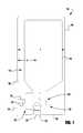
- FIG. 1is a cross-section of an exemplary foam dispenser 100 having a refill unit 110 ;
- FIG. 2is a cross-section of an exemplary refill unit 200 ;
- FIG. 3is a cross-section of another exemplary refill unit 300 .
- FIG. 1illustrates an exemplary embodiment of a foam dispenser 100 .
- the cross-section of FIG. 1is taken through the housing 102 to show the foam pump 120 and container 116 .
- Foam dispenser 100includes a disposable refill unit 110 .
- the disposable refill unit 110includes a container 116 connected to a foam pump 120 .
- the foam dispenser 100may be a wall-mounted system, a counter-mounted system, an un-mounted portable system movable from place to place or any other kind of foam dispenser system.
- the container 116forms a liquid reservoir that contains a supply of a foamable liquid within the disposable refill unit 110 .
- the contained liquidcould be for example a soap, a sanitizer, a cleanser, a disinfectant or some other foamable liquid.
- the container 116is a collapsible container and can be made of thin plastic or a flexible bag-like material.
- the container 116may be formed by a rigid housing member, or have any other suitable configuration for containing the foamable liquid without leaking.
- the container 116may advantageously be refillable, replaceable or both refillable and replaceable. In other embodiments, the container 116 may be neither refillable nor replaceable.
- the installed refill unit 110may be removed from the foam dispenser 100 .
- the empty or failed disposable refill unit 110may then be replaced with a new disposable refill unit 110 .
- the housing 102 of the foam dispenser 100contains one or more actuating members 104 to activate the pump 120 .
- actuator or actuating members or mechanismincludes one or more parts that cause the dispenser 100 to move liquid, air or foam.
- Actuator 104is generically illustrated because there are many different kinds of pump actuators which may be employed in the foam dispenser 100 .
- the actuator of the foam dispenser 100may be any type of actuator such as, for example, a manual lever, a manual pull bar, a manual push bar, a manual rotatable crank, an electrically activated actuator or other means for actuating the foam pump 120 which includes a liquid pump portion 124 and air compressor portion 122 .
- Electronic actuatorsmay additionally include a sensor to provide for a hands-free dispenser system with touchless operation.
- actuator 104is connected to housing 102 by a hinge member 106 .
- Various intermediate linkagessuch as for example linkage 105 , connect the actuator member 104 to the foam pump 120 within the system housing 102 .
- linkage 105has a socket 107 that snaps onto a ball 241 ( FIG. 2 ) at the proximate end of piston 240 .
- An aperture 115 in bottom plate 103 of housing 102allows foam dispensed from the nozzle 125 of foam pump 120 to be dispensed to a user.
- one advantage of the exemplary embodiments of the present inventionis that the outlet of the foam pump 120 may be offset from the liquid inlet.
- a more compact housing 102may be used.
- the distance X from the front of the housing 102 to the centerline of the outlet nozzle 125is between about 1.25 and 2.5 inches.
- the distance Xis between about 1.5 and 2 inches, and in one embodiment the distance is about 1.7 inches from the front of the housing.
- the overall depth Y of housing 102is less than about 5 inches, and in another embodiment the overall depth Y is about 4 inches.
- FIG. 2is a cross-sectional view of an exemplary embodiment of a refill unit 200 suitable for use in foam dispensers.
- Refill unit 200includes a container 221 for holding a foamable liquid connected to a foam pump 201 .
- Liquid pump 201includes a housing 202 .
- Housing 202receives inlet plate 216 .
- Inlet plate 216includes an annular projection 218 .
- a neck of a container 221is received within an annular groove 222 formed between annular projection 218 and housing 202 .
- Housing 202may be connected to the container 221 by any means such as, for example, a threaded connection, a welded connection, an adhesive connection or the like.
- a gasketmay fit in annular groove 222 to help form a liquid tight seal with the container 221 .
- Inlet plate 216may be integrally formed with housing 202 .
- Inlet plate 216includes one or more inlet apertures 224 located therethrough.
- one-way inlet valve 226is secured to inlet plate 216 .
- One-way inlet valve 226may be any type of one-way valve such as, for example, a ball and spring valve, a poppet valve, a flapper valve, an umbrella valve, a slit valve, a mushroom valve, a duck bill valve or the like.
- Pump housing 202includes a liquid chamber 204 .
- liquid chamber 204is cylindrical.
- a sleeve 232Located at least partially within liquid chamber 204 is a sleeve 232 .
- Housing 202includes an annular projection 210 at one end of the liquid chamber 204 .
- Sleeve 232is secured to annular projecting member 210 by collar 211 .
- Collar 211includes an aperture 212 .
- a piston 240includes a shaft 241 that projects through aperture 212 .
- Piston 240is slideable in a reciprocating manner within sleeve 232 .
- Piston 240includes a piston head having a double wiper seal 244 located at the distal end. Movement of piston 240 causes the volume of liquid chamber 204 to expand and contract.
- Double wiper seal 244may be any type of sealing member such as, for example, an o-ring, a single wiper seal or the like.
- Housing 202includes a projecting member 206 that contacts an end 207 of piston 240 to stop movement of piston 240 when it reaches the end of its stroke.
- piston 240includes a second piston head and sealing member 242 located at the proximal end of piston 240 .
- Second sealing member 242engages the inside of the air compressor housing 230 .
- the term “air compressor”may be used interchangeably herein with the term “air pump.”
- air compressor housing 230 and sleeve 232are formed as one piece. Movement of piston 240 causes air chamber 243 to expand and contract.
- Air chamber 243includes an air outlet 236 , which is also an air inlet to mixing chamber 262 .
- air outlet 236is integrally formed with both sleeve 232 and air compressor housing 230 .
- a liquid inlet passageway 250is formed between sleeve 232 and the wall of liquid chamber 204 .
- the liquid inlet passageway 250may extend entirely around sleeve 232 or may be enclosed by one or more rib projections (not shown) that cause liquid in inlet passageway 250 to flow through passage 250 and passage 252 into the interior of sleeve 232 .
- Outlet passages 254 , 256also exist between sleeve 232 and the walls of liquid chamber 204 .
- Outlet passageway 256may extend entirely around sleeve 232 or may be enclosed by one or more rib projections (not shown) that cause liquid to flow from the interior of sleeve 232 through passageways 254 , 256 .
- Passageway 254 and passageway 250may be connected to form a common passageway.
- Housing 202includes an outlet passage 208 .
- Lower housing 260may be connected to housing 202 by any means such as, for example, a threaded connection, a snap-fit connection, a welded connection an adhesive connection or the like.
- lower housing 260includes annular projection 267 that snaps onto annular projection 209 of housing 202 .
- Located proximate outlet passage 208is a liquid outlet valve 264 .
- Liquid outlet valve 264includes a slit 266 . Slit 266 opens to allow liquid to flow from liquid chamber 204 into mixing chamber 262 .
- liquid outlet valve 264is retained in place by annular rim 263 on lower housing member 260 . While a slit valve is shown and advantageously takes up very little room, other types of liquid outlet valves may be used such as, for example, a ball and spring valve, a flapper valve, a poppet valve, a mushroom valve, a duck-bill valve or the like.
- Lower housing 260has an interior cavity that forms a mixing chamber 262 .
- Lower housing 260includes an opening 273 in the wall of mixing chamber 262 .
- the air outlet 236 of air chamber 243is fitted into opening 273 to allow mixing chamber 262 to be in fluid communication with air chamber 243 .
- Mixing chamber 262is in fluid communication with liquid chamber 204 through valve 264 .
- lower housing 260includes an outlet opening 261 and a lower annular projection 267 .
- Outlet nozzle 270fits over lower projection 267 to secure outlet nozzle 270 to lower housing 260 .
- Outlet nozzle 270is secured using a press-fit connection, but may be connected by other means such as, for example, a snap-fit connection, an adhesive, a threaded connection or the like.
- Outlet nozzle 270includes a floor 271 , a tapered portion 272 and an outlet 274 .
- a foaming media 275such as one or more screens, is included in outlet nozzle 270 .
- a foaming cartridgemay be used whereby the foaming cartridge rests on floor 271 .
- screens 275are replaced by one or more porous members or baffles.
- liquid inlets 224 , or liquid inlet valve 226may be positioned over any portion of the sleeve 232 without effecting the volume of liquid chamber 204 or reducing the efficiency of pump 201 .
- the liquid outlet 208 and/or liquid outlet valve 264may be located along any portion of the sleeve 232 without reducing the volume of liquid chamber 204 or reducing the efficiency of pump 201 .
- the liquid inlet and the liquid outletare off-set from one another.
- the liquid outletis located closer to the front of a dispenser than the liquid inlet when the pump 201 is installed in the foam dispenser.
- the liquid inlet and liquid outletare along a common axis.
- the piston 240may move along a pump axis that is substantially horizontal.
- the liquid inlet valve 226moves along an axis that is substantially normal to the pump axis.
- at least a portion of the liquid inlet valve 226moves along a substantially vertical axis even though it may collapse both horizontally and vertically.
- pump 201has been described as being made of selected sub-parts, pump 201 , as well as the other embodiments of pumps disclosed herein, may be made from more sub-parts or fewer sub-parts.
- liquidflows in through liquid inlets 224 , past one-way inlet valve 226 , into liquid chamber 204 , through passages 250 , 252 and into the interior of sleeve 232 , which also forms a portion of the liquid chamber 204 .
- Movement of piston 240 from the charged position to the discharged positioncauses fluid to flow out of the liquid chamber 204 (including the center of the sleeve 232 ) through passages 254 , 256 , past liquid outlet valve 264 and into mixing chamber 262 . Simultaneously, the volume of air chamber 243 is reduced and air flows out of air outlet 236 into mixing chamber 262 . The air and liquid mixture is forced through opening 261 and through foam media 275 to create a rich foam. The rich foam travels through tapered section 272 where it accelerates due to the reduced volume and exits foam pump 201 through outlet 274 .
- FIG. 3is a cross-sectional view of another exemplary embodiment of a refill unit 300 suitable for use in foam dispensers.
- Refill unit 300includes a container 321 for holding a foamable liquid connected to a liquid pump 301 .
- Liquid pump 301includes a housing 302 .
- Housing 302receives inlet plate 316 .
- Inlet plate 316includes a annular projection 318 .
- a neck of a container 321is received within an annular groove 322 formed between annular projection 318 and housing 302 .
- Housing 302may be connected to the container 321 by any means such as, for example, a threaded connection, a welded connection, an adhesive connection or the like.
- Inlet plate 316may be integrally formed with housing 302 .
- Inlet plate 316includes one or more inlet apertures 324 located therethrough.
- one-way inlet valve 326is secured to inlet plate 316 .
- One-way inlet valve 326may be any type of one-way valve such as, for example, a ball and spring, a poppet valve, a flapper valve, an umbrella valve, a slit valve, a mushroom valve, a duck-bill valve or the like.
- Pump housing 302includes a liquid chamber 304 .
- liquid chamber 304is cylindrical.
- a sleeve 332Located at least partially within liquid chamber 304 is a sleeve 332 .
- Housing 302includes an annular projection 310 at one end of the liquid chamber 304 .
- Sleeve 332is secured to annular projecting member 310 by collar 311 .
- Collar 311includes an aperture 312 .
- a piston 340includes a shaft 341 that projects through aperture 312 . Piston 340 is slideable in a reciprocating manner within sleeve 332 . Piston 340 includes a piston head having a double wiper seal 344 located at the distal end. Movement of piston 340 causes the volume of liquid chamber 304 to expand and contract. Double wiper seal 344 may be any type of sealing member such as, for example, an o-ring, a single wiper seal or the like. Housing 302 includes a projecting member 306 that contacts an end 307 of piston 340 to stop movement of piston 340 when it reaches the end of its stroke.
- piston 340includes a second piston head and sealing member 342 located at the proximal end. Second sealing member 342 engages the inside of the air compressor housing 330 .
- air compressormay be used interchangeably herein with the term “air pump.”
- air compressor housing 330 and sleeve 332are formed as one piece. Movement of piston head 342 expands and contracts air chamber 343 .
- Air chamber 343includes an air outlet 336 , which is also an air inlet to mixing chamber 396 .
- air outlet 336is integrally formed with both sleeve 332 and air compressor housing 330 .
- a liquid inlet passageway 350is formed between sleeve 332 and the wall of liquid chamber 304 .
- the inlet passageway 350may extend entirely around sleeve 332 or may be enclosed by one or more rib projections (not shown) that cause liquid in inlet passageway 350 to flow through passage 350 and passage 352 into the interior of sleeve 332 .
- Outlet passages 354 , 356also exists between sleeve 332 and liquid chamber 304 .
- Outlet passageway 356may extend entirely around sleeve 332 or may be enclosed by one or more rib projections (not shown) that cause liquid to flow through passageways 354 , 356 from the interior of sleeve 332 .
- Passageway 354 and passageway 350may be connected to form a common passageway.
- Housing 302includes a liquid outlet opening 308 and valve seat 366 .
- Housing 302includes projecting member 309 that engages with projecting member 367 of lower housing 370 to form a snap-fit connection.
- lower housing 370may be connected to housing 302 by any means such as, for example, a threaded connection, a press-fit connection, a welded connection, an adhesive connection or the like.
- Lower housing 370has an interior cavity 373 .
- Lower housing 370also includes a first annular projection 365 that forms an air inlet 336 .
- lower housing 370includes a floor 371 .
- a tapered section 372extends from floor 371 to annular outlet 374 .
- Insert 390may be made of one or more components. Insert 390 includes an interior cavity 396 formed by annular member 392 . Interior cavity 396 retains one-way outlet valve 364 and biasing member 368 . Interior cavity 396 is also the mixing chamber. One-way outlet valve 364 seals against valve seat 366 .
- One-way outlet valve 364may be any type of one-way valve such as, for example, a ball and spring valve, a poppet valve, a flap valve, an umbrella valve, a slit valve or the like.
- Insert 390includes an opening 394 to allow liquid and air to flow down and through foaming media 375 secured therein.
- Foaming media 375may be one or more screens, porous members, baffles, sponges, foaming cartridges, a combination thereof or the like.
- Foaming media 375may be an integral part of insert 390 or may be a separate part.
- pump 301has been described as being made of selected sub-parts, pump 301 , as well as the other embodiments of pumps disclosed herein, may be made from more sub-parts or fewer sub-parts.
- liquidflows in through liquid inlets 324 , past one-way inlet valve 326 into liquid chamber 304 and through passages 350 , 352 and into the interior of sleeve 332 (which also forms a portion of the liquid chamber 304 ).
- Movement of piston 340 from the charged position to the discharged positioncauses fluid to flow out of the liquid chamber 304 (including the center of the sleeve 332 through passages 354 , 356 past liquid outlet valve 364 into mixing chamber 396 .
- the volume of air chamber 343is reduced and air flows out of air outlet 336 into cavity 373 , up around annular projection 392 and mixes with the liquid in mixing chamber 396 .
- the air and liquid mixtureis forced through opening 394 and through foam media 375 to create a rich foam.
- the rich foamtravels through tapered section 372 where it accelerates due to the reduced volume and exits foam pump 301 through outlet 374 .
- the air compressors and liquid pumps described hereinmay include biasing members to return them to a charged or primed state.
- a biasing member in the actuator mechanismreturns the air compressor and/or liquid pump to a first state. Still yet, if the air compressor and/or liquid pump are electrically operated, they may be moved to the first state electronically.
Landscapes
- Health & Medical Sciences (AREA)
- Public Health (AREA)
- Containers And Packaging Bodies Having A Special Means To Remove Contents (AREA)
- Closures For Containers (AREA)
Abstract
Description
Claims (17)
Priority Applications (3)
| Application Number | Priority Date | Filing Date | Title |
|---|---|---|---|
| US13/792,011US9179808B2 (en) | 2012-08-30 | 2013-03-09 | Horizontal pumps, refill units and foam dispensers |
| TW102130034ATW201429860A (en) | 2012-08-30 | 2013-08-22 | Horizontal pumps, refill units and foam dispensers |
| PCT/US2013/056549WO2014035847A1 (en) | 2012-08-30 | 2013-08-26 | Horizontal pumps, refill units and foam dispensers |
Applications Claiming Priority (2)
| Application Number | Priority Date | Filing Date | Title |
|---|---|---|---|
| US201261695140P | 2012-08-30 | 2012-08-30 | |
| US13/792,011US9179808B2 (en) | 2012-08-30 | 2013-03-09 | Horizontal pumps, refill units and foam dispensers |
Publications (2)
| Publication Number | Publication Date |
|---|---|
| US20140061245A1 US20140061245A1 (en) | 2014-03-06 |
| US9179808B2true US9179808B2 (en) | 2015-11-10 |
Family
ID=49117977
Family Applications (1)
| Application Number | Title | Priority Date | Filing Date |
|---|---|---|---|
| US13/792,011ActiveUS9179808B2 (en) | 2012-08-30 | 2013-03-09 | Horizontal pumps, refill units and foam dispensers |
Country Status (3)
| Country | Link |
|---|---|
| US (1) | US9179808B2 (en) |
| TW (1) | TW201429860A (en) |
| WO (1) | WO2014035847A1 (en) |
Cited By (5)
| Publication number | Priority date | Publication date | Assignee | Title |
|---|---|---|---|---|
| US9854947B2 (en)* | 2012-08-23 | 2018-01-02 | Gojo Industries, Inc. | Horizontal pumps, refill units and foam dispensers with integral air compressors |
| US11744413B2 (en) | 2021-10-07 | 2023-09-05 | Deb Ip Limited | Dispenser assembly |
| US11744412B2 (en) | 2021-10-07 | 2023-09-05 | Deb Ip Limited | Dispenser system |
| US12185884B2 (en) | 2021-10-07 | 2025-01-07 | Deb Ip Limited | Dispenser |
| USD1061260S1 (en) | 2023-07-18 | 2025-02-11 | S. C. Johnson & Son, Inc. | Dispenser |
Families Citing this family (19)
| Publication number | Priority date | Publication date | Assignee | Title |
|---|---|---|---|---|
| US20130320043A1 (en)* | 2012-05-30 | 2013-12-05 | Gojo Industries, Inc. | Double acting valve for liquid pumps |
| US9266134B2 (en)* | 2012-12-11 | 2016-02-23 | Gojo Industries, Inc. | Vented check valves, pumps and refill units with vented check valves |
| US9648992B2 (en) | 2013-12-19 | 2017-05-16 | Gojo Industries, Inc. | Pumps with vents to vent inverted containers and refill units having non-collapsing containers |
| CA2841279C (en)* | 2014-01-29 | 2021-11-23 | Heiner Ophardt | Multiple air chamber foam pump |
| JP6734780B2 (en) | 2014-02-24 | 2020-08-05 | ゴジョ・インダストリーズ・インコーポレイテッド | Non-vented collapsible container, refillable refill container, dispenser and refill unit |
| US9596963B2 (en) | 2014-07-30 | 2017-03-21 | Gojo Industries, Inc. | Vented refill units and dispensers having vented refill units |
| US20160128351A1 (en) | 2014-10-09 | 2016-05-12 | Trade Secret Chocolates | System and methods for distributing and dispensing chocolates |
| US11064712B2 (en) | 2014-10-09 | 2021-07-20 | Trade Secret Chocolates | Systems and methods for distributing and dispensing chocolate |
| US10993457B2 (en) | 2014-10-09 | 2021-05-04 | Trade Secret Chocolates | Systems and methods for distributing and dispensing chocolate |
| US11224233B2 (en) | 2015-10-09 | 2022-01-18 | Trade Secret Chocolates | Systems and methods for distributing and dispensing chocolate |
| US10952454B2 (en) | 2014-10-09 | 2021-03-23 | Trade Secret Chocolates | Systems and methods for distributing and dispensing chocolate |
| US10112038B2 (en) | 2015-02-09 | 2018-10-30 | Vernay Laboratories, Inc. | Umbrella check valve with reduced hemolysis |
| JP6869945B2 (en)* | 2015-07-15 | 2021-05-12 | ゴジョ・インダストリーズ・インコーポレイテッド | Foam cartridge, refill unit, foam dispenser, and foam dispenser system |
| US10022024B2 (en)* | 2015-10-23 | 2018-07-17 | Gojo Industries, Inc. | Rotary peristaltic dome pump |
| US9834182B2 (en)* | 2015-12-08 | 2017-12-05 | Beto Engineering & Marketing Co., Ltd. | Portable tubeless tire inflating device |
| AU2018234913B2 (en)* | 2017-03-16 | 2023-07-27 | True Essence Foods Inc. | Systems and methods for distributing and dispensing chocolate |
| TWI650181B (en)* | 2017-09-13 | 2019-02-11 | 集泉塑膠工業股份有限公司 | Downward liquid dispenser |
| WO2022207072A1 (en)* | 2021-03-29 | 2022-10-06 | Essity Hygiene And Health Aktiebolag | Pump assembly with shield |
| CN113414040B (en)* | 2021-06-10 | 2023-10-20 | 江西华冠钢结构有限公司 | Mixed spraying device for manufacturing light building materials |
Citations (55)
| Publication number | Priority date | Publication date | Assignee | Title |
|---|---|---|---|---|
| US2904222A (en) | 1955-02-07 | 1959-09-15 | Imp Brass Mfg Co | Soap dispenser |
| GB1269545A (en) | 1968-11-08 | 1972-04-06 | Perpedos Ab | Improvements relating to devices for dispensing pastes or liquids |
| US3851801A (en) | 1971-02-15 | 1974-12-03 | Involvo Ag Verpackungsmaschine | Dispensing device having lost motion piston pump |
| US4168020A (en) | 1976-09-30 | 1979-09-18 | Dispenso Ag | Dispensing apparatus for discharging liquid or creamy products |
| US4330071A (en) | 1979-10-15 | 1982-05-18 | Ab Tranas Rostfria | Dispensing device for discharging a liquid or pasty product from a container, containing such a product |
| US4360130A (en)* | 1979-10-16 | 1982-11-23 | Duskin Franchise Kabushiki Kaisha | Dispenser, particularly for liquid soap |
| US4793522A (en) | 1987-06-15 | 1988-12-27 | Calmar, Inc. | Positive discharge valve for viscous product dispenser |
| US4880161A (en) | 1985-01-28 | 1989-11-14 | Earl Wright Company | Foam dispensing device |
| CH676227A5 (en) | 1988-05-02 | 1990-12-28 | Proma Ag | Dispenser for cleaning or disinfecting material - has fluid reservoir and piston with lower air mixing head |
| US4986453A (en) | 1989-05-15 | 1991-01-22 | The Pittway Corporation | Atomizing pump |
| US5100030A (en) | 1990-05-24 | 1992-03-31 | Inopak Ltd. | Fixtures for fluid dispensing bags |
| US5174476A (en) | 1991-05-06 | 1992-12-29 | Steiner Company, Inc. | Liquid soap dispensing system |
| US5209377A (en) | 1991-05-06 | 1993-05-11 | Steiner Robert L | Disposable refill cartridge for a liquid soap dispensing system |
| US5271530A (en) | 1990-11-07 | 1993-12-21 | Daiwa Can Company | Foam dispensing pump container |
| US5439140A (en) | 1992-02-21 | 1995-08-08 | Steiner Company, Inc. | Method of and apparatus for dispensing batches of soap lather |
| US5439144A (en) | 1993-12-27 | 1995-08-08 | Steiner Company, Inc. | Liquid soap dispensing system |
| US5445288A (en) | 1994-04-05 | 1995-08-29 | Sprintvest Corporation Nv | Liquid dispenser for dispensing foam |
| US5462208A (en) | 1994-08-01 | 1995-10-31 | The Procter & Gamble Company | Two-phase dispensing systems utilizing bellows pumps |
| US5556005A (en)* | 1995-01-09 | 1996-09-17 | Sprintvest Corporation Nv | Collapsible soap dispenser |
| GB2301812A (en) | 1995-06-08 | 1996-12-18 | Steiner Co Int Sa | Apparatus for supplying liquid soap to a foaming device |
| US5605256A (en)* | 1994-12-20 | 1997-02-25 | Fan; Chen-Yueh | Fluid dispenser apparatus |
| US5799841A (en) | 1996-06-21 | 1998-09-01 | Minnesota Mining And Manufacturing Company | Drip resistant nozzle for a dispenser |
| US5823397A (en)* | 1997-04-15 | 1998-10-20 | Masco Corporation | Personal hygiene liquids dispenser with an improved valve seat |
| US5826755A (en) | 1995-12-18 | 1998-10-27 | Koller Enterprises, Inc. | Liquid dispenser with selectably attachable actuator |
| US5862954A (en) | 1994-07-18 | 1999-01-26 | Cws International Ag | Device for producing soap lather and use thereof |
| US5899363A (en) | 1997-12-22 | 1999-05-04 | Owens-Illinois Closure Inc. | Pump dispenser having a locking system with detents |
| US5906299A (en) | 1995-03-29 | 1999-05-25 | Hagleitner Betriebshygiene Ges.M.B.H. & Co. Kg | Soap foam dispenser |
| US6016936A (en)* | 1998-06-18 | 2000-01-25 | Fan; Chen-Yueh | Liquid dispenser |
| EP1147818A1 (en) | 2000-04-20 | 2001-10-24 | Supermatic Kunststoff Ag | Device for producing and discharging foam |
| US6409050B1 (en) | 2001-03-20 | 2002-06-25 | Hygiene-Technik Inc. | Liquid dispenser for dispensing foam |
| US6446840B2 (en) | 2000-05-18 | 2002-09-10 | Ophardt Product Kg | Apparatus for making and dispensing foam |
| US20030000967A1 (en)* | 2000-01-19 | 2003-01-02 | Markus Ehrensperger | Mehod and device for the controlled dispensing of cleansing foam |
| US20040031816A1 (en) | 2002-08-15 | 2004-02-19 | Schuman Allan L. | Foam soap dispenser for push operation |
| US20040206772A1 (en) | 2003-04-18 | 2004-10-21 | Leifheit David H. | Bottle adapter for dispensing of cleanser from bottle used in an automated cleansing sprayer |
| WO2005105320A1 (en) | 2004-04-29 | 2005-11-10 | Airspray N.V. | Dispensing device |
| US20050258192A1 (en) | 2004-05-07 | 2005-11-24 | Matthews Shaun K | Method of producing foamed cleaser with suspended particles therein and a dispenser therefore |
| US20050284887A1 (en)* | 2004-06-25 | 2005-12-29 | Kimberly-Clark Worldwide, Inc. | Self-contained viscous liquid dispenser with a foaming pump |
| US7059282B2 (en) | 1997-12-11 | 2006-06-13 | Jacobs Vehicle Systems, Inc. | Variable lost motion valve actuator and method |
| US20060273114A1 (en) | 2005-04-22 | 2006-12-07 | Heiner Ophardt | Stepped pump foam dispenser |
| US20070272709A9 (en) | 2003-10-25 | 2007-11-29 | Ciavarella Nick E | Universal collar key |
| US7377758B2 (en) | 2003-09-05 | 2008-05-27 | Brightwell Dispensers Limited | Fluid pump |
| US20080272148A1 (en) | 2004-03-29 | 2008-11-06 | Polynest Technologies Ltd | Self Contained Foam Dispenser |
| US20090008408A1 (en) | 2007-06-18 | 2009-01-08 | Heiner Ophardt | Optically keyed dispenser |
| US7537140B2 (en)* | 2006-01-06 | 2009-05-26 | Yeng-Tang Lin | Liquid soap dispenser |
| EP2080464A2 (en) | 2008-01-18 | 2009-07-22 | GOJO Industries, Inc. | Squeeze action foam pump |
| EP2080560A1 (en) | 2008-01-18 | 2009-07-22 | GOJO Industries, Inc. | Foam dispenser with liquid tube pump refill unit |
| US20100096412A1 (en) | 2002-04-17 | 2010-04-22 | Rieke Corporation | Pump dispensers |
| US20100147894A1 (en) | 2005-12-22 | 2010-06-17 | Johnsondiversey, Inc. | Lock-out device and method |
| US7815076B2 (en) | 2002-04-26 | 2010-10-19 | Gotohti.Com Inc. | Vacuum released valve |
| GB2472235A (en) | 2009-07-29 | 2011-02-02 | Brightwell Dispensers Ltd | Dispensing device with disposable pump |
| US20110079614A1 (en) | 2009-10-04 | 2011-04-07 | G.A.B. Development & Engineering B.V. | Fluid product dispenser |
| WO2011157975A1 (en) | 2010-06-15 | 2011-12-22 | Bright Innovations Limited | Foam pump |
| US20140124531A1 (en) | 2012-02-16 | 2014-05-08 | Dispensing Dynamics International | Dispenser apparatus for dispensing liquid soap, lotion or other liquid |
| US20140217117A1 (en) | 2013-02-06 | 2014-08-07 | Op-Hygiene Ip Gmbh | Base Grooved Collapsible Bottle |
| US8814005B2 (en)* | 2012-04-27 | 2014-08-26 | Pibed Limited | Foam dispenser |
- 2013
- 2013-03-09USUS13/792,011patent/US9179808B2/enactiveActive
- 2013-08-22TWTW102130034Apatent/TW201429860A/enunknown
- 2013-08-26WOPCT/US2013/056549patent/WO2014035847A1/enactiveApplication Filing
Patent Citations (62)
| Publication number | Priority date | Publication date | Assignee | Title |
|---|---|---|---|---|
| US2904222A (en) | 1955-02-07 | 1959-09-15 | Imp Brass Mfg Co | Soap dispenser |
| GB1269545A (en) | 1968-11-08 | 1972-04-06 | Perpedos Ab | Improvements relating to devices for dispensing pastes or liquids |
| US3851801A (en) | 1971-02-15 | 1974-12-03 | Involvo Ag Verpackungsmaschine | Dispensing device having lost motion piston pump |
| US4168020A (en) | 1976-09-30 | 1979-09-18 | Dispenso Ag | Dispensing apparatus for discharging liquid or creamy products |
| US4330071A (en) | 1979-10-15 | 1982-05-18 | Ab Tranas Rostfria | Dispensing device for discharging a liquid or pasty product from a container, containing such a product |
| US4360130A (en)* | 1979-10-16 | 1982-11-23 | Duskin Franchise Kabushiki Kaisha | Dispenser, particularly for liquid soap |
| US4880161A (en) | 1985-01-28 | 1989-11-14 | Earl Wright Company | Foam dispensing device |
| US4793522A (en) | 1987-06-15 | 1988-12-27 | Calmar, Inc. | Positive discharge valve for viscous product dispenser |
| CH676227A5 (en) | 1988-05-02 | 1990-12-28 | Proma Ag | Dispenser for cleaning or disinfecting material - has fluid reservoir and piston with lower air mixing head |
| US4986453A (en) | 1989-05-15 | 1991-01-22 | The Pittway Corporation | Atomizing pump |
| US5100030A (en) | 1990-05-24 | 1992-03-31 | Inopak Ltd. | Fixtures for fluid dispensing bags |
| US5271530A (en) | 1990-11-07 | 1993-12-21 | Daiwa Can Company | Foam dispensing pump container |
| US5174476A (en) | 1991-05-06 | 1992-12-29 | Steiner Company, Inc. | Liquid soap dispensing system |
| US5209377A (en) | 1991-05-06 | 1993-05-11 | Steiner Robert L | Disposable refill cartridge for a liquid soap dispensing system |
| US5439140A (en) | 1992-02-21 | 1995-08-08 | Steiner Company, Inc. | Method of and apparatus for dispensing batches of soap lather |
| US5439144A (en) | 1993-12-27 | 1995-08-08 | Steiner Company, Inc. | Liquid soap dispensing system |
| US5445288A (en) | 1994-04-05 | 1995-08-29 | Sprintvest Corporation Nv | Liquid dispenser for dispensing foam |
| US5862954A (en) | 1994-07-18 | 1999-01-26 | Cws International Ag | Device for producing soap lather and use thereof |
| US5462208A (en) | 1994-08-01 | 1995-10-31 | The Procter & Gamble Company | Two-phase dispensing systems utilizing bellows pumps |
| US5605256A (en)* | 1994-12-20 | 1997-02-25 | Fan; Chen-Yueh | Fluid dispenser apparatus |
| US5556005A (en)* | 1995-01-09 | 1996-09-17 | Sprintvest Corporation Nv | Collapsible soap dispenser |
| US5906299A (en) | 1995-03-29 | 1999-05-25 | Hagleitner Betriebshygiene Ges.M.B.H. & Co. Kg | Soap foam dispenser |
| GB2301812A (en) | 1995-06-08 | 1996-12-18 | Steiner Co Int Sa | Apparatus for supplying liquid soap to a foaming device |
| US5826755A (en) | 1995-12-18 | 1998-10-27 | Koller Enterprises, Inc. | Liquid dispenser with selectably attachable actuator |
| US5799841A (en) | 1996-06-21 | 1998-09-01 | Minnesota Mining And Manufacturing Company | Drip resistant nozzle for a dispenser |
| US5823397A (en)* | 1997-04-15 | 1998-10-20 | Masco Corporation | Personal hygiene liquids dispenser with an improved valve seat |
| US7059282B2 (en) | 1997-12-11 | 2006-06-13 | Jacobs Vehicle Systems, Inc. | Variable lost motion valve actuator and method |
| US5899363A (en) | 1997-12-22 | 1999-05-04 | Owens-Illinois Closure Inc. | Pump dispenser having a locking system with detents |
| US6065647A (en) | 1997-12-22 | 2000-05-23 | Owens-Illinois Closure Inc. | Pump dispenser having a locking system with detents |
| US6016936A (en)* | 1998-06-18 | 2000-01-25 | Fan; Chen-Yueh | Liquid dispenser |
| US6626332B2 (en) | 2000-01-19 | 2003-09-30 | Hts International Trading Ag | Method and device for the controlled dispensing of cleansing foam |
| US20030000967A1 (en)* | 2000-01-19 | 2003-01-02 | Markus Ehrensperger | Mehod and device for the controlled dispensing of cleansing foam |
| EP1147818A1 (en) | 2000-04-20 | 2001-10-24 | Supermatic Kunststoff Ag | Device for producing and discharging foam |
| US6446840B2 (en) | 2000-05-18 | 2002-09-10 | Ophardt Product Kg | Apparatus for making and dispensing foam |
| US6409050B1 (en) | 2001-03-20 | 2002-06-25 | Hygiene-Technik Inc. | Liquid dispenser for dispensing foam |
| US20100096412A1 (en) | 2002-04-17 | 2010-04-22 | Rieke Corporation | Pump dispensers |
| US7815076B2 (en) | 2002-04-26 | 2010-10-19 | Gotohti.Com Inc. | Vacuum released valve |
| US20040031816A1 (en) | 2002-08-15 | 2004-02-19 | Schuman Allan L. | Foam soap dispenser for push operation |
| US20040206772A1 (en) | 2003-04-18 | 2004-10-21 | Leifheit David H. | Bottle adapter for dispensing of cleanser from bottle used in an automated cleansing sprayer |
| US6971549B2 (en) | 2003-04-18 | 2005-12-06 | S.C. Johnson & Son, Inc. | Bottle adapter for dispensing of cleanser from bottle used in an automated cleansing sprayer |
| US7377758B2 (en) | 2003-09-05 | 2008-05-27 | Brightwell Dispensers Limited | Fluid pump |
| US20070272709A9 (en) | 2003-10-25 | 2007-11-29 | Ciavarella Nick E | Universal collar key |
| US20080272148A1 (en) | 2004-03-29 | 2008-11-06 | Polynest Technologies Ltd | Self Contained Foam Dispenser |
| WO2005105320A1 (en) | 2004-04-29 | 2005-11-10 | Airspray N.V. | Dispensing device |
| US20050258192A1 (en) | 2004-05-07 | 2005-11-24 | Matthews Shaun K | Method of producing foamed cleaser with suspended particles therein and a dispenser therefore |
| US20050284887A1 (en)* | 2004-06-25 | 2005-12-29 | Kimberly-Clark Worldwide, Inc. | Self-contained viscous liquid dispenser with a foaming pump |
| US20060273114A1 (en) | 2005-04-22 | 2006-12-07 | Heiner Ophardt | Stepped pump foam dispenser |
| US20100147894A1 (en) | 2005-12-22 | 2010-06-17 | Johnsondiversey, Inc. | Lock-out device and method |
| US7537140B2 (en)* | 2006-01-06 | 2009-05-26 | Yeng-Tang Lin | Liquid soap dispenser |
| US20090008408A1 (en) | 2007-06-18 | 2009-01-08 | Heiner Ophardt | Optically keyed dispenser |
| EP2080560A1 (en) | 2008-01-18 | 2009-07-22 | GOJO Industries, Inc. | Foam dispenser with liquid tube pump refill unit |
| EP2080464A2 (en) | 2008-01-18 | 2009-07-22 | GOJO Industries, Inc. | Squeeze action foam pump |
| US8579159B2 (en) | 2008-01-18 | 2013-11-12 | Gojo Industries, Inc. | Squeeze action foam pump |
| GB2472235A (en) | 2009-07-29 | 2011-02-02 | Brightwell Dispensers Ltd | Dispensing device with disposable pump |
| WO2011012836A1 (en) | 2009-07-29 | 2011-02-03 | Brightwell Dispensers Limited | Foam pump |
| US20120217267A1 (en) | 2009-07-29 | 2012-08-30 | Etienne Vincent Bunoz | Foam pump |
| US20110079614A1 (en) | 2009-10-04 | 2011-04-07 | G.A.B. Development & Engineering B.V. | Fluid product dispenser |
| WO2011157975A1 (en) | 2010-06-15 | 2011-12-22 | Bright Innovations Limited | Foam pump |
| US20130315031A1 (en) | 2010-06-15 | 2013-11-28 | Etienne Bunoz | Foam pump |
| US20140124531A1 (en) | 2012-02-16 | 2014-05-08 | Dispensing Dynamics International | Dispenser apparatus for dispensing liquid soap, lotion or other liquid |
| US8814005B2 (en)* | 2012-04-27 | 2014-08-26 | Pibed Limited | Foam dispenser |
| US20140217117A1 (en) | 2013-02-06 | 2014-08-07 | Op-Hygiene Ip Gmbh | Base Grooved Collapsible Bottle |
Non-Patent Citations (8)
| Title |
|---|
| European Patent Office Search Report issued Jan. 7, 2011 in EP Application No. 09 150 880.2; 4 pages. |
| International Search Report and Written Opinion from International Application No. PCT/US2013/056106, date of mailing Nov. 7, 2013; 10 pages. |
| International Search Report and Written Opinion from International Application No. PCT/US2013/056549, date of mailing Jan. 15, 2014; 16 pages. |
| International Search Report and Written Opinion from International Application No. PCT/US2013/056964, date of mailing Nov. 7, 2013; 12 pages. |
| International Search Report and Written Opinion from International Application No. PCT/US2013/067158, date of mailing Apr. 11, 2014; 16 pages. |
| International Search Report and Written Opinion from International Application No. PCT/US2013/067366, date of mailing Apr. 11, 2014; 18 pages. |
| International Search Report and Written Opinion from International Application No. PCT/US2014/012440, date of mailing Jun. 23, 2014. |
| International Search Report and Written Opinion from International Application No. PCT/US2014/035072, date of mailing Jul. 23, 2014. |
Cited By (6)
| Publication number | Priority date | Publication date | Assignee | Title |
|---|---|---|---|---|
| US9854947B2 (en)* | 2012-08-23 | 2018-01-02 | Gojo Industries, Inc. | Horizontal pumps, refill units and foam dispensers with integral air compressors |
| US11744413B2 (en) | 2021-10-07 | 2023-09-05 | Deb Ip Limited | Dispenser assembly |
| US11744412B2 (en) | 2021-10-07 | 2023-09-05 | Deb Ip Limited | Dispenser system |
| US12185884B2 (en) | 2021-10-07 | 2025-01-07 | Deb Ip Limited | Dispenser |
| US12303079B2 (en) | 2021-10-07 | 2025-05-20 | Deb Ip Limited | Dispenser system |
| USD1061260S1 (en) | 2023-07-18 | 2025-02-11 | S. C. Johnson & Son, Inc. | Dispenser |
Also Published As
| Publication number | Publication date |
|---|---|
| US20140061245A1 (en) | 2014-03-06 |
| WO2014035847A1 (en) | 2014-03-06 |
| TW201429860A (en) | 2014-08-01 |
Similar Documents
| Publication | Publication Date | Title |
|---|---|---|
| US9179808B2 (en) | Horizontal pumps, refill units and foam dispensers | |
| US9307871B2 (en) | Horizontal pumps, refill units and foam dispensers | |
| US20140367419A1 (en) | Foam cartridges, pumps, refill units and foam dispensers utilizing the same | |
| EP2948255B1 (en) | Pumps with container vents | |
| US9854947B2 (en) | Horizontal pumps, refill units and foam dispensers with integral air compressors | |
| CA2933828C (en) | A refill unit having a non-collapsing container and a foam-pump with a vent to vent said container | |
| CN104411412B (en) | Low Residue Inverted Pumps, Dispensers and Refill Units | |
| JP2016506782A5 (en) | ||
| US9392913B2 (en) | Horizontal pumps with reduced part count, refill units and dispensers | |
| JP2017502740A5 (en) |
Legal Events
| Date | Code | Title | Description |
|---|---|---|---|
| AS | Assignment | Owner name:GOJO INDUSTRIES, INC., OHIO Free format text:ASSIGNMENT OF ASSIGNORS INTEREST;ASSIGNORS:MCNULTY, JOHN J.;CIAVARELLA, NICK E.;TEDEROUS, CORY;AND OTHERS;SIGNING DATES FROM 20120919 TO 20120925;REEL/FRAME:030424/0980 | |
| STCF | Information on status: patent grant | Free format text:PATENTED CASE | |
| MAFP | Maintenance fee payment | Free format text:PAYMENT OF MAINTENANCE FEE, 4TH YEAR, LARGE ENTITY (ORIGINAL EVENT CODE: M1551); ENTITY STATUS OF PATENT OWNER: LARGE ENTITY Year of fee payment:4 | |
| AS | Assignment | Owner name:PNC BANK, NATIONAL ASSOCIATION, PENNSYLVANIA Free format text:SECURITY INTEREST;ASSIGNOR:GOJO INDUSTRIES, INC.;REEL/FRAME:051228/0667 Effective date:20101029 | |
| MAFP | Maintenance fee payment | Free format text:PAYMENT OF MAINTENANCE FEE, 8TH YEAR, LARGE ENTITY (ORIGINAL EVENT CODE: M1552); ENTITY STATUS OF PATENT OWNER: LARGE ENTITY Year of fee payment:8 | |
| AS | Assignment | Owner name:PNC BANK, NATIONAL ASSOCIATION, PENNSYLVANIA Free format text:SECURITY INTEREST;ASSIGNOR:GOJO INDUSTRIES, INC.;REEL/FRAME:065369/0253 Effective date:20231026 | |
| AS | Assignment | Owner name:SILVER POINT FINANCE, LLC, AS COLLATERAL AGENT, CONNECTICUT Free format text:SECURITY INTEREST;ASSIGNOR:GOJO INDUSTRIES, INC.;REEL/FRAME:065382/0587 Effective date:20231026 |