US9179153B2 - Refined depth map - Google Patents
Refined depth mapDownload PDFInfo
- Publication number
- US9179153B2 US9179153B2US12/737,838US73783809AUS9179153B2US 9179153 B2US9179153 B2US 9179153B2US 73783809 AUS73783809 AUS 73783809AUS 9179153 B2US9179153 B2US 9179153B2
- Authority
- US
- United States
- Prior art keywords
- depth information
- picture
- target
- reference picture
- view
- Prior art date
- Legal status (The legal status is an assumption and is not a legal conclusion. Google has not performed a legal analysis and makes no representation as to the accuracy of the status listed.)
- Active, expires
Links
Images


Classifications
- H—ELECTRICITY
- H04—ELECTRIC COMMUNICATION TECHNIQUE
- H04N—PICTORIAL COMMUNICATION, e.g. TELEVISION
- H04N19/00—Methods or arrangements for coding, decoding, compressing or decompressing digital video signals
- H04N19/10—Methods or arrangements for coding, decoding, compressing or decompressing digital video signals using adaptive coding
- H04N19/102—Methods or arrangements for coding, decoding, compressing or decompressing digital video signals using adaptive coding characterised by the element, parameter or selection affected or controlled by the adaptive coding
- H04N19/132—Sampling, masking or truncation of coding units, e.g. adaptive resampling, frame skipping, frame interpolation or high-frequency transform coefficient masking
- H04N13/0022—
- H—ELECTRICITY
- H04—ELECTRIC COMMUNICATION TECHNIQUE
- H04N—PICTORIAL COMMUNICATION, e.g. TELEVISION
- H04N13/00—Stereoscopic video systems; Multi-view video systems; Details thereof
- H04N13/10—Processing, recording or transmission of stereoscopic or multi-view image signals
- H04N13/106—Processing image signals
- H04N13/128—Adjusting depth or disparity
- H—ELECTRICITY
- H04—ELECTRIC COMMUNICATION TECHNIQUE
- H04N—PICTORIAL COMMUNICATION, e.g. TELEVISION
- H04N19/00—Methods or arrangements for coding, decoding, compressing or decompressing digital video signals
- H04N19/10—Methods or arrangements for coding, decoding, compressing or decompressing digital video signals using adaptive coding
- H04N19/134—Methods or arrangements for coding, decoding, compressing or decompressing digital video signals using adaptive coding characterised by the element, parameter or criterion affecting or controlling the adaptive coding
- H04N19/162—User input
- H—ELECTRICITY
- H04—ELECTRIC COMMUNICATION TECHNIQUE
- H04N—PICTORIAL COMMUNICATION, e.g. TELEVISION
- H04N19/00—Methods or arrangements for coding, decoding, compressing or decompressing digital video signals
- H04N19/46—Embedding additional information in the video signal during the compression process
- H—ELECTRICITY
- H04—ELECTRIC COMMUNICATION TECHNIQUE
- H04N—PICTORIAL COMMUNICATION, e.g. TELEVISION
- H04N19/00—Methods or arrangements for coding, decoding, compressing or decompressing digital video signals
- H04N19/50—Methods or arrangements for coding, decoding, compressing or decompressing digital video signals using predictive coding
- H04N19/597—Methods or arrangements for coding, decoding, compressing or decompressing digital video signals using predictive coding specially adapted for multi-view video sequence encoding
- H—ELECTRICITY
- H04—ELECTRIC COMMUNICATION TECHNIQUE
- H04N—PICTORIAL COMMUNICATION, e.g. TELEVISION
- H04N19/00—Methods or arrangements for coding, decoding, compressing or decompressing digital video signals
- H04N19/60—Methods or arrangements for coding, decoding, compressing or decompressing digital video signals using transform coding
- H04N19/61—Methods or arrangements for coding, decoding, compressing or decompressing digital video signals using transform coding in combination with predictive coding
- H—ELECTRICITY
- H04—ELECTRIC COMMUNICATION TECHNIQUE
- H04N—PICTORIAL COMMUNICATION, e.g. TELEVISION
- H04N2213/00—Details of stereoscopic systems
- H04N2213/005—Aspects relating to the "3D+depth" image format
Definitions
- Implementationsare described that relate to coding systems. Various particular implementations relate to a refined depth map.
- Multi-view Video Codingis a key technology that serves a wide variety of applications, including free-viewpoint and three-dimensional (3D) video applications, home entertainment and surveillance.
- depth datamay be associated with each view. Depth data is generally essential for view synthesis. In those multi-view applications, the amount of video and depth data involved is typically enormous. Thus, there exists at least the desire for a framework that helps improve the coding efficiency of current video coding solutions performing simulcast of independent views.
- a multi-view video sourceincludes multiple views of the same scene. As a result, there typically exists a high degree of correlation between the multiple view images. Therefore, view redundancy can be exploited in addition to temporal redundancy. View redundancy can be exploited by, for example, performing view prediction across the different views.
- 3DV systemsmay encode partial views and the other views will be reconstructed using view synthesis.
- the residual signal for the skipped viewsmay be sent if higher quality is required.
- the synthesized picturescan serve as references to encode the subsequent pictures.
- depth information for a picture in a set of picturesis accessed.
- Modified depth information for the pictureis accessed.
- a refinementis determined that characterizes a difference between the depth information and the modified depth information.
- the refinement, and the depth informationare provided for use in processing one or more pictures in the set of pictures.
- depth information for a picture in a set of picturesis accessed.
- a refinementis accessed that characterizes a difference between the depth information for the picture and modified depth information for the picture.
- the modified depth information for the pictureis determined.
- One or more pictures in the set of picturesare processed using the modified depth information.
- implementationsmay be configured or embodied in various manners.
- an implementationmay be performed as a method, or embodied as apparatus, such as, for example, an apparatus configured to perform a set of operations or an apparatus storing instructions for performing a set of operations, or embodied in a signal.
- apparatussuch as, for example, an apparatus configured to perform a set of operations or an apparatus storing instructions for performing a set of operations, or embodied in a signal.
- FIG. 1is a diagram of an implementation of an encoder.
- FIG. 2is a diagram of an implementation of a decoder.
- FIG. 3is a diagram of an implementation of a video transmission system.
- FIG. 4is a diagram of an implementation of a video receiving system.
- FIG. 5is a diagram of an implementation of a video processing device.
- FIG. 6is a diagram of an implementation of a system for transmitting and receiving multi-view video with depth information.
- FIG. 8is a diagram of an example of using a refined depth map to create a virtual reference view.
- FIG. 9is a diagram of an implementation of an encoding process.
- FIG. 10is a diagram further illustrating step 920 of FIG. 9 and step 1210 of FIG. 12 .
- FIG. 11is a diagram of another example of using a refined depth map to create a virtual reference view.
- FIG. 12is a diagram of an implementation of an encoding process.
- FIG. 13is a diagram of an implementation of a decoding process.
- FIG. 14is a diagram of an implementation of an encoding process.
- FIG. 15is a diagram of an implementation of a decoding process.
- FIG. 16is a diagram of an implementation of an encoding process.
- FIG. 17is a diagram of an implementation of a decoding process.
- FIG. 18is a diagram of an implementation of a decoding process.
- a subsequent viewmay use view 1 as a reference by warping view 1 to the location of the subsequent view.
- Such warpinggenerally requires/uses the depth of the reference view 1 .
- a large residuemay result in the predictive coding of the subsequent view, and so we may refine the depth of view 1 to get better coding results.
- Such a processresults in two depth maps (DMs) and both depth maps may be sent, or as explained in various implementations in this application, one depth map and a one refinement may be sent.
- One depth mapis good for coding and the original depth map is good for rendering at the decoder (synthesizing a virtual view for the viewer).
- the coding depth mapis used, for example, to generate additional reference views (for coding/decoding).
- the rendering depth mapis used, for example, to generate additional views for the user. These two purposes may have different measures of quality. A depth map may be good for coding, but produce subjectively lousy views to look at, for example. However, sending two depth maps is expensive.
- Warping a reference viewcan be done by forward warping using a view's depth, or by reverse warping in which we warp the view's depth and use that warped depth to look back (reverse warp) to get a reference view's pixels that belong in (correspond to) a given location in a warped reference view.
- a refinementcan be coded in a number of ways. For example, as a third component, in which case it may be predictively encoded using other refinements, or as another image in a sequence or another view.
- Depth imagesmay be obtained by external means that are out of the control of the encoder and decoder, which are transmitted for rendering purposes.
- the depth images for rendering purposesmay not be efficient for coding purposes.
- the inventorshave determined that it is not an optimal solution if the two versions of the depth images are independently coded and transmitted.
- the original depth imagesare used for rendering purposes, and the modified depth images are used for coding.
- the refinement of the original depth imagesimproves the coding efficiency.
- a multiple-view video sequenceis a set of two or more video sequences that capture the same scene from different viewpoints.
- At least one implementationcan also be applied to quality scalable coding, where better quality can be achieved for coded/synthesized views by receiving additional depth refinement.
- the techniques describedare not limited to multiple view coding, and can be applied to multiple depth coding too.
- the present principlescan be applied to depth map encoding. That is, we can refine a depth map, and use the refinement to predictively encode the depth map at another view. The encoding would involve, for example, warping the refined depth map to the location of the “other view” and using the warped map as a reference to predictively encode the original depth map for this “other view”.
- depth informationis a general term referring to various kinds of information about depth.
- One type of depth informationis a “depth map”, which generally refers to a per-pixel depth image.
- Other types of depth informationinclude, for example, using a single depth value for each coded block rather than for each coded pixel. Further, depth information may be provided for an entire picture, or for less than the entire picture by focusing on, for example, foreground objects.
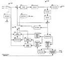
- FIG. 1shows an exemplary video encoder 100 to which the present principles may be applied, in accordance with an embodiment of the present principles.
- the encoder 100includes a combiner 105 having an output connected in signal communication with an input of a transformer 110 .
- An output of the transformer 110is connected in signal communication with an input of quantizer 115 .
- An output of the quantizer 115is connected in signal communication with an input of an entropy coder 120 and an input of an inverse quantizer 125 .
- An output of the inverse quantizer 125is connected in signal communication with an input of an inverse transformer 130 .
- An output of the inverse transformer 130is connected in signal communication with a first non-inverting input of a combiner 135 .
- An output of the combiner 135is connected in signal communication with an input of an intra predictor 145 and an input of a deblocking filter 150 .
- a first output of the deblocking filter 150is connected in signal communication with an input of a reference picture store 155 (for temporal prediction) and a first input of a reference picture store 160 (for inter-view prediction).
- An output of the reference picture store 155is connected in signal communication with a first input of a motion compensator 175 and a first input of a motion estimator 180 .
- An output of the motion estimator 180is connected in signal communication with a second input of the motion compensator 175 .
- An output of the reference picture store 160is connected in signal communication with a first input of a disparity estimator 170 and a first input of a disparity compensator 165 .
- An output of the disparity estimator 170is connected in signal communication with a second input of the disparity compensator 165 .
- a second output of the deblocking filter 150is connected in signal communication with an input of a reference picture store 171 (for virtual picture generation).
- a first output of the reference picture store 171is connected in signal communication with a first input of a view synthesizer 172 and a first input of a virtual reference view controller and depth refiner 173 .
- a first output of the virtual reference view controller 173is connected in signal communication with a second input of the view synthesizer 172 .
- An output of the entropy decoder 120 , a second output of the virtual reference view controller 173 , a first output of a mode decision module 195 , and a first output of a view selector 102 ,are each available as respective outputs of the encoder 100 , for outputting a bitstream.
- a second input of the virtual reference view controller and depth refiner 173is available as an input to the encoder 100 , for receiving an in-band or out-of-band depth signal.
- a first input (for picture data for view i) and a second input (for picture data for view j) of a switch 188are each available as respective inputs to the encoder 100 .
- An output (for providing a synthesized view) of the view synthesizer 172is connected in signal communication with a second input of the reference picture store 160 .
- a second output of the view selector 102determines which input (e.g., picture data for view i, view j, or a synthesized view) is provided to the switch 188 .
- An output of the switch 188is connected in signal communication with a non-inverting input of the combiner 105 , a third input of the motion compensator 175 , a second input of the motion estimator 180 , and a second input of the disparity estimator 170 .
- An output of an intra predictor 145is connected in signal communication with a first input of a switch 185 .
- An output of the disparity compensator 165is connected in signal communication with a second input of the switch 185 .
- An output of the motion compensator 175is connected in signal communication with a third input of the switch 185 .
- An output of the mode decision module 195determines which input is provided to the switch 185 .
- An output of a switch 185is connected in signal communication with a second non-inverting input of the combiner 135 and with an inverting input of the combiner 105 .
- FIG. 1Portions of FIG. 1 may also be referred to as an encoder, an encoding unit, or an accessing unit, such as, for example, blocks 110 , 115 , and 120 , either individually or collectively.
- blocks 125 , 130 , 135 , and 150may be referred to as a decoder or decoding unit, either individually or collectively.
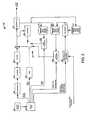
- FIG. 2shows an exemplary decoder 200 to which the present principles may be applied, in accordance with an embodiment of the present principles.
- the decoder 200includes an entropy decoder 205 having an output connected in signal communication with an input of an inverse quantizer 210 .
- An output of the inverse quantizeris connected in signal communication with an input of an inverse transformer 215 .
- An output of the inverse transformer 215is connected in signal communication with a first non-inverting input of a combiner 220 .
- An output of the combiner 220is connected in signal communication with an input of a deblocking filter 225 and an input of an intra predictor 230 .
- a first output of the deblocking filter 225is connected in signal communication with an input of a reference picture store 240 (for temporal prediction), a first input of a reference picture store 245 (for inter-view prediction), and an input of a reference picture store 272 (for virtual picture generation).
- An output of the reference picture store 240is connected in signal communication with a first input of a motion compensator 235 .
- An output of a reference picture store 245is connected in signal communication with a first input of a disparity compensator 250 .
- An output of a bitstream receiver 201is connected in signal communication with an input of a bitstream parser 202 .
- a first output (for providing a residue bitstream) of the bitstream parser 202is connected in signal communication with an input of the entropy decoder 205 .
- a second output (for providing control syntax to control which input is selected by the switch 255 ) of the bitstream parser 202is connected in signal communication with an input of a mode selector 222 .
- a third output (for providing a motion vector) of the bitstream parser 202is connected in signal communication with a second input of the motion compensator 235 .
- a fourth output (for providing a disparity vector and/or illumination offset) of the bitstream parser 202is connected in signal communication with a second input of the disparity compensator 250 .
- a fifth output (for providing virtual reference view control and depth refinement information) of the bitstream parser 202is connected in signal communication with a first input of a virtual reference view controller and depth refiner 288 .
- An output of the virtual reference view controller and depth refiner 288is connected in signal communication with a first input of the view synthesizer 271 .
- An output of the view synthesizer 271is connected in signal communication with a second input of the reference picture store 245 .
- An output of the reference picture store 272is connected in signal communication with a second input of the view synthesizer 271 .
- illumination offsetis an optional input and may or may not be used, depending upon the implementation.
- An output of a switch 255is connected in signal communication with a second non-inverting input of the combiner 220 .
- a first input of the switch 255is connected in signal communication with an output of the disparity compensator 250 .
- a second input of the switch 255is connected in signal communication with an output of the motion compensator 235 .
- a third input of the switch 255is connected in signal communication with an output of the intra predictor 230 .
- An output of the mode module 222is connected in signal communication with the switch 255 for controlling which input is selected by the switch 255 .
- An output of the deblocking filter 225is available as an output of the decoder.
- a second input of the virtual reference controller and depth refiner 288is available as an input to the decoder 200 , for receiving an in-band or out-of-band depth signal.
- FIG. 2may also be referred to as an accessing unit, such as, for example, bitstream parser 202 and any other block that provides access to a particular piece of data or information, either individually or collectively.
- blocks 205 , 210 , 215 , 220 , and 225may be referred to as a decoder or decoding unit, either individually or collectively.
- FIG. 3shows an exemplary video transmission system 300 to which the present principles may be applied, in accordance with an implementation of the present principles.
- the video transmission system 300may be, for example, a head-end or transmission system for transmitting a signal using any of a variety of media, such as, for example, satellite, cable, telephone-line, or terrestrial broadcast.
- the transmissionmay be provided over the Internet or some other network.
- the video transmission system 300is capable of generating and delivering video content encoded using inter-view skip mode with depth. This is achieved by generating an encoded signal(s) including depth information or information capable of being used to synthesize the depth information at a receiver end that may, for example, have a decoder.
- the video transmission system 300includes an encoder 310 and a transmitter 320 capable of transmitting the encoded signal.
- the encoder 310receives video information and generates an encoded signal(s) there from using inter-view skip mode with depth.
- the encoder 310may be, for example, the encoder 300 described in detail above.
- the encoder 310may include sub-modules, including for example an assembly unit for receiving and assembling various pieces of information into a structured format for storage or transmission.
- the various pieces of informationmay include, for example, coded or uncoded video, coded or uncoded depth information, and coded or uncoded elements such as, for example, motion vectors, coding mode indicators, and syntax elements.
- the transmitter 320may be, for example, adapted to transmit a program signal having one or more bitstreams representing encoded pictures and/or information related thereto. Typical transmitters perform functions such as, for example, one or more of providing error-correction coding, interleaving the data in the signal, randomizing the energy in the signal, and modulating the signal onto one or more carriers.
- the transmittermay include, or interface with, an antenna (not shown). Accordingly, implementations of the transmitter 320 may include, or be limited to, a modulator.
- FIG. 4shows an exemplary video receiving system 400 to which the present principles may be applied, in accordance with an embodiment of the present principles.
- the video receiving system 400may be configured to receive signals over a variety of media, such as, for example, satellite, cable, telephone-line, or terrestrial broadcast.
- the signalsmay be received over the Internet or some other network.
- the video receiving system 400may be, for example, a cell-phone, a computer, a set-top box, a television, or other device that receives encoded video and provides, for example, decoded video for display to a user or for storage.
- the video receiving system 400may provide its output to, for example, a screen of a television, a computer monitor, a computer (for storage, processing, or display), or some other storage, processing, or display device.
- the video receiving system 400is capable of receiving and processing video content including video information.
- the video receiving system 400includes a receiver 410 capable of receiving an encoded signal, such as for example the signals described in the implementations of this application, and a decoder 420 capable of decoding the received signal.
- the receiver 410may be, for example, adapted to receive a program signal having a plurality of bitstreams representing encoded pictures. Typical receivers perform functions such as, for example, one or more of receiving a modulated and encoded data signal, demodulating the data signal from one or more carriers, de-randomizing the energy in the signal, de-interleaving the data in the signal, and error-correction decoding the signal.
- the receiver 410may include, or interface with, an antenna (not shown). Implementations of the receiver 410 may include, or be limited to, a demodulator.
- the decoder 420outputs video signals including video information and depth information.
- the decoder 420may be, for example, the decoder 400 described in detail above.
- FIG. 5shows an exemplary video processing device 500 to which the present principles may be applied, in accordance with an embodiment of the present principles.
- the video processing device 500may be, for example, a set top box or other device that receives encoded video and provides, for example, decoded video for display to a user or for storage.
- the video processing device 500may provide its output to a television, computer monitor, or a computer or other processing device.
- the video processing device 500includes a front-end (FE) device 505 and a decoder 510 .
- the front-end device 505may be, for example, a receiver adapted to receive a program signal having a plurality of bitstreams representing encoded pictures, and to select one or more bitstreams for decoding from the plurality of bitstreams. Typical receivers perform functions such as, for example, one or more of receiving a modulated and encoded data signal, demodulating the data signal, decoding one or more encodings (for example, channel coding and/or source coding) of the data signal, and/or error-correcting the data signal.
- the front-end device 505may receive the program signal from, for example, an antenna (not shown). The front-end device 505 provides a received data signal to the decoder 510 .
- the decoder 510receives a data signal 520 .
- the data signal 520may include, for example, one or more Advanced Video Coding (AVC), Scalable Video Coding (SVC), or Multi-view Video Coding (MVC) compatible streams.
- AVCAdvanced Video Coding
- SVCScalable Video Coding
- MVCMulti-view Video Coding
- AVCrefers more specifically to the existing International Organization for Standardization/International Electrotechnical Commission (ISO/IEC) Moving Picture Experts Group-4 (MPEG-4) Part 10 Advanced Video Coding (AVC) standard/International Telecommunication Union, Telecommunication Sector (ITU-T) H.264 Recommendation (hereinafter the “H.264/MPEG-4 AVC Standard” or variations thereof, such as the “AVC standard” or simply “AVC”).
- ISO/IECInternational Organization for Standardization/International Electrotechnical Commission
- MPEG-4Moving Picture Experts Group-4
- AVCAdvanced Video Coding
- ITU-TInternational Telecommunication Union, Telecommunication Sector
- H.264/MPEG-4 AVC StandardH.264 Recommendation
- MVCrefers more specifically to a multi-view video coding (“MVC”) extension (Annex H) of the AVC standard, referred to as H.264/MPEG-4 AVC, MVC extension (the “MVC extension” or simply “MVC”).
- MVCmulti-view video coding
- SVCrefers more specifically to a scalable video coding (“SVC”) extension (Annex G) of the AVC standard, referred to as H.264/MPEG-4 AVC, SVC extension (the “SVC extension” or simply “SVC”).
- SVCscalable video coding
- the decoder 510decodes all or part of the received signal 520 and provides as output a decoded video signal 530 .
- the decoded video 530is provided to a selector 550 .
- the device 500also includes a user interface 560 that receives a user input 570 .
- the user interface 560provides a picture selection signal 580 , based on the user input 570 , to the selector 550 .
- the picture selection signal 580 and the user input 570indicate which of multiple pictures, sequences, scalable versions, views, or other selections of the available decoded data a user desires to have displayed.
- the selector 550provides the selected picture(s) as an output 590 .
- the selector 550uses the picture selection information 580 to select which of the pictures in the decoded video 530 to provide as the output 590 .
- the selector 550includes the user interface 560 , and in other implementations no user interface 560 is provided because the selector 550 receives the user input 570 directly without a separate interface function being performed.
- the selector 550may be implemented in software or as an integrated circuit, for example.
- the selector 550is incorporated with the decoder 510 , and in another implementation, the decoder 510 , the selector 550 , and the user interface 560 are all integrated.
- front-end 505receives a broadcast of various television shows and selects one for processing. The selection of one show is based on user input of a desired channel to watch. Although the user input to front-end device 505 is not shown in FIG. 5 , front-end device 505 receives the user input 570 .
- the front-end 505receives the broadcast and processes the desired show by demodulating the relevant part of the broadcast spectrum, and decoding any outer encoding of the demodulated show.
- the front-end 505provides the decoded show to the decoder 510 .
- the decoder 510is an integrated unit that includes devices 560 and 550 .
- the decoder 510thus receives the user input, which is a user-supplied indication of a desired view to watch in the show.
- the decoder 510decodes the selected view, as well as any required reference pictures from other views, and provides the decoded view 590 for display on a television (not shown).
- the usermay desire to switch the view that is displayed and may then provide a new input to the decoder 510 .
- the decoder 510decodes both the old view and the new view, as well as any views that are in between the old view and the new view. That is, the decoder 510 decodes any views that are taken from cameras that are physically located in between the camera taking the old view and the camera taking the new view.
- the front-end device 505also receives the information identifying the old view, the new view, and the views in between. Such information may be provided, for example, by a controller (not shown in FIG. 5 ) having information about the locations of the views, or the decoder 510 .
- Other implementationsmay use a front-end device that has a controller integrated with the front-end device.
- the decoder 510provides all of these decoded views as output 590 .
- a post-processor(not shown in FIG. 5 ) interpolates between the views to provide a smooth transition from the old view to the new view, and displays this transition to the. user. After transitioning to the new view, the post-processor informs (through one or more communication links not shown) the decoder 510 and the front-end device 505 that only the new view is needed. Thereafter, the decoder 510 only provides as output 590 the new view.
- the system 500may be used to receive multiple views of a sequence of images, and to present a single view for display, and to switch between the various views in a smooth manner.
- the smooth mannermay involve interpolating between views to move to another view.
- the system 500may allow a user to rotate an object or scene, or otherwise to see a three-dimensional representation of an object or a scene.
- the rotation of the objectfor example, may correspond to moving from view to view, and interpolating between the views to obtain a smooth transition between the views or simply to obtain a three-dimensional representation. That is, the user may “select” an interpolated view as the “view” that is to be displayed.
- 3D Videois a new framework that includes a coded representation for multiple view video and depth information and targets the generation of high-quality 3D rendering at the receiver. This enables 3D visual experiences with auto-multiscopic displays.
- FIG. 6shows an exemplary system 600 for transmitting and receiving multi-view video with depth information, to which the present principles may be applied, according to an embodiment of the present principles.
- video datais indicated by a solid line
- depth datais indicated by a dashed line
- meta datais indicated by a dotted line.
- the system 600may be, for example, but is not limited to, a free-viewpoint television system.
- the system 600includes a three-dimensional (3D) content producer 620 , having a plurality of inputs for receiving one or more of video, depth, and meta data from a respective plurality of sources.
- 3Dthree-dimensional
- Such sourcesmay include, but are not limited to, a stereo camera 611 , a depth camera 612 , a multi-camera setup 613 , and 2-dimensional/3-dimensional (2D/3D) conversion processes 614 .
- One or more networks 630may be used for transmit one or more of video, depth, and meta data relating to multi-view video coding (MVC) and digital video broadcasting (DVB).
- MVCmulti-view video coding
- DVDdigital video broadcasting
- a depth image-based renderer 650performs depth image-based rendering to project the signal to various types of displays.
- the depth image-based renderer 650is capable of receiving display configuration information and user preferences.
- An output of the depth image-based renderer 650may be provided to one or more of a 2D display 661 , an M-view 3D display 662 , and/or a head-tracked stereo display 663 .
- the framework 700involves an auto-stereoscopic 3D display 710 , which supports output of multiple views, a first depth image-based renderer 720 , a second depth image-based renderer 730 , and a buffer for decoded data 740 .
- the decoded datais a representation known as Multiple View plus Depth (MVD) data.
- MVDMultiple View plus Depth
- the nine camerasare denoted by V 1 through V 9 .
- Corresponding depth maps for the three input viewsare denoted by D 1 , D 5 , and D 9 .
- Any virtual camera positions in between the captured camera positionse.g., Pos 1 , Pos 2 , Pos 3
- the available depth mapsD 1 , D 5 , D 9
- FIG. 7the baseline between the actual cameras (V 1 , V 5 and V 9 ) used to capture data can be large.
- the correlation between these camerasis significantly reduced and coding efficiency of these cameras may suffer since the coding efficiency would only rely on temporal correlation.
- FIG. 7the baseline between the actual cameras (V 1 , V 5 and V 9 ) used to capture data can be large.
- the correlation between these camerasis significantly reduced and coding efficiency of these cameras may suffer since the coding efficiency would only rely on temporal correlation.
- FIG. 7the baseline between the actual cameras (V 1 , V 5 and V 9 ) used to capture data can be large.
- views 2 , 3 , 4 , 6 , 7 and 8are skipped in coding.
- the decoderwill use view 1 , 5 and 9 and their depth images. Note that the depth images for view 5 are obtained for rendering the missed views.
- a different depth image for view 5may be identified. Thus, two different depth images for view 5 will be coded.
- the encodercan send the residual signal for selected pictures or views among the skipped views (i.e., views 2 , 3 , 4 , 6 , 7 and 8 in FIG. 7 ) to enhance the rendering quality.
- the original depth imagestarget for the best rendering quality.
- the original depth imagesare delivered to the receiver side so as to be utilized by the 3D display based on DIBR.
- Any multi-view video coding frameworkcan be used for the encoding and transmission of the original depth map, e.g., MPEG-C part III, or the 3 DV under development.
- FIG. 8shows an example 800 of using a refined the depth map to create a virtual reference view, in accordance with an embodiment of the present principles.
- VR xyrepresents a virtual reference, synthesized from view x to view y using the refined depth of view x.
- view 2apart from view 0 , view 2 has an additional reference view, virtual view 2 , which is synthesized from view 0 using the refined depth map of view 0 .
- virtual view 1is generated as an additional reference for view 1 .
- the depth map refinementis associated with the reference views.
- each view among views 0 , 2 , 4 and 6has one associated refined depth map, while views 1 , 3 , and 5 have no associated refined depth map.
- FIG. 9shows an exemplary method 900 for encoding a frame, in accordance with an embodiment of the present principles.
- the frame to be coded in view iis accessed.
- the reference picture listis constructed.
- a loopis performed over each reference view j to construct and add a warped reference view into the reference picture list.
- step 908may pass control to step 904 , not step 910 if the loop is not finished.
- step 904it is determined whether or not there is a refined depth map for reference view j. If so, then control is passed to a step 906 . Otherwise, control is passed to a step 905 .
- the depth mapis set to the reconstructed depth map for a coding purpose.
- the reference viewis warped to the position of view i.
- the warped reference viewis added to the reference picture list.
- the frameis encoded with the augmented reference picture buffer.
- the encoded depth map(for a rendering purpose) is accessed.
- a call 1000i.e., to method 1000 of FIG. 10 ) is made, which involves getting the refined depth map for this frame (for a view coding purpose) with another view to be predicted as an input parameter.
- step 922is it determined whether or not the refined depth map is available. If so, then control is passed to a step 923 . Otherwise, control is passed to the step 930 .
- the depth map refinementnamely the difference from the two versions of the depth maps, is found.
- the depth map refinementis encoded.
- the encoded frame and the depth refinement if it existsare written to a bitstream.
- the depth mapis set to the encoded depth map for a rendering purpose.
- step 925may involve, for example, predictively encoding the refinement using a previous refinement as a reference.
- step 925may involve, for example, the refinement including separate information at one of more levels of a hierarchy for the picture.
- the hierarchymay include two or more of a pixel level, a partition level, a macroblock level, a slice level, and a picture level.
- the refinementincludes a separate value for each pixel represented by the refinement.
- the refinementincludes a separate value for each macroblock represented by the refinement, where the separate value for a given macroblock applies to each pixel within the given macroblock.
- one or more of the depth information for the picture, the modified depth information for the picture, and the refinementapply only to a portion of the picture.
- FIG. 10shows an exemplary method 1000 for refining a depth map, in accordance with an embodiment of the present principles.
- the method 1000may be considered as one exemplary implementation of step 920 of method 900 of Figure. 9 and step 1210 of method 1200 of FIG. 12 .
- a target view that will use the current view as a referenceis taken as an input parameter.
- CodingCostp revis set to an infinite value.
- DepthMap curis set as the original depth map.
- view synthesisis performed to generate the virtual view at the position of a target view using DepthMap curr .
- the coding cost CodingCost curris estimated when using the virtual view view as a reference.
- step 1036it is determined whether or not CodingCost is diverging. If so, then control is passed to a step 1037 . Otherwise, control is passed to a step 1040 .
- step 1037it is ascertained that refining the depth map has failed and a return is made to the caller (i.e., step 920 of method 900 of FIG. 9 ).
- DepthMap previs set as DepthMap curr .
- depth estimationis performed based on DepthMap prev to obtain DepthMap curr .
- CodingCost previs set to CodingCost curr .
- the refined depth mapis set and returned to the caller (i.e., step 920 of method 900 of FIG. 9 ).
- the depth estimation, view synthesis, and coding cost estimationare repeated until the change of the coding cost falls within a threshold value or the coding cost is smaller than Threshold codingcost or the coding cost is found to be diverging. This is a time-consuming procedure since depth estimation and view synthesis are complex.
- the modification of the depth mapcan be coded using an existing video coding standard like AVC.
- MVCcan be used to code the multi-view depth refinement.
- the depth signalcan be scalably coded and, thus, different operating points can be extracted for different purposes. As an example, if only view synthesis is required, then a lower operating point (corresponding to a lower quality depth map may be extracted). Otherwise, if both view synthesis and virtual reference view generation are required, then a higher operating point (corresponding to a higher quality depth map) may be extracted.
- FIG. 17shows an exemplary method 1700 for decoding a frame, in accordance with an embodiment of the present principles.
- the method 1700may be performed, for example, to decode frames encoded using method 900 of FIG. 9 .
- a bitstream including an encoded frame i and possible a depth refinementis read.
- a reference picture listis constructed.
- a loopis performed over each reference view j to construct and add a warped reference view into the reference picture list.
- step 1708may pass control to step 1704 , not step 1720 if the loop is not finished.
- step 1704it is determined whether or not there is a refined depth map for reference view j. If so, then control is passed to a step 1706 . Otherwise, control is passed to a step 1705 .
- a depth mapis set to the reconstructed refined depth map for a coding purpose.
- the reference viewis warped to the position of view i.
- the warped reference viewis added into the reference picture list.
- a step 1720the frame is decoded with an augmented reference picture buffer.
- the decoded frameis put into an output buffer after all slices in the frame are decoded.
- the decoded depth map(for a rendering purpose) is accessed.
- the depth map refinementis decoded.
- the associated depth mapis refined.
- the depth mapis set to the encoded depth map for a rendering purpose.
- step 1750may involve, for example, predictively encoding the refinement using a previous refinement as a reference.
- one or more of the depth information for the picture, the modified depth information for the picture, and the refinementapply only to a portion of the picture.
- FIG. 16shows an exemplary method 1600 for encoding a slice using a refined depth of a current view, in accordance with an embodiment of the present principles.
- the frame to be coded in view iis accessed.
- the reference picture listis constructed.
- a loopis performed over each reference view j to construct and add a warped reference view into the reference picture list.
- step 1608may pass control to step 1604 , not step 1610 if the loop is not finished.
- the depth mapis set to the reconstructed refined depth map for a coding purpose.
- the depth map from the reference location view jis warped to the location of view i.
- the correspondence for pixels of blocks between view i and view jis obtained.
- every block of the frameis encoded based on the correspondence when it favors rate distortion optimization, otherwise every block of the frame is encoded in the usual manner (for example, in accordance with a particular standard, recommendation, and/or so forth).
- the encoded depth map(for a rendering purpose) is accessed.
- the refined depth map for this frame(for a view coding purpose) is obtained with another view to be predicted as an input parameter.
- the depth map refinementnamely the difference from the two versions of depth maps, is found.
- the depth map refinementis encoded.
- the encoded frame and the depth refinement if it existsare written to a bitstream.
- the depth mapis set to the encoded depth map for a rendering purpose.
- FIG. 18shows an exemplary method 1800 for decoding a frame, in accordance with an embodiment of the present principles.
- a bitstream including an encoded frame i and possible a depth refinementis read.
- a reference picture listis constructed.
- a loopis performed over each reference view j to construct and add a warped reference view into the reference picture list.
- step 1808may pass control to step 1804 , not step 18210 if the loop is not finished.
- a depth mapis set to the reconstructed refined depth map for a coding purpose.
- the depth map from the refererice location view jis warped to the location of view i.
- correspondence for pixels or blocks between view i and view jis obtained.
- a step 1820every block of the current frame is decoded based on the correspondence when it is signaled, otherwise every block is decoded in the usual manner (for example, in accordance with a particular standard, recommendation, and/or so forth).
- the decoded frameis put into an output buffer after all slices in the frame are decoded.
- it is determined whether or not the current viewis a reference view. If so, then control is passed to a step 1840 . Otherwise, the method is terminated.
- the decoded depth map(for a rendering purpose) is accessed.
- the depth map refinementis decoded.
- the associated depth mapis refined.
- the depth mapis set to the encoded depth map for a rendering purpose.
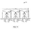
- FIG. 11shows another example 1100 of using a refined depth map to create a virtual reference view, in accordance with an embodiment of the present principles.
- RD xyrepresents a refined depth map of view x to generate a synthesized view to predict view y
- VR xyrepresents a virtual reference, synthesized from view x to view y using the refined depth of view x.
- view 2is associated with one refined depth that originates from view 0
- view 1is associated with two refined depth maps that originate from view 0 and view 2 , respectively. That is, the depth of view 0 has two refined versions.
- This embodimentprovides more flexibility to achieve the depth map refinement compared to embodiment 1 and, thus, benefits the coding efficiency.
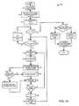
- FIG. 12shows an exemplary method 1200 for encoding a P or B slice with additional reference views generated based on a refined depth map, in accordance with an embodiment of the present principles.
- the depth map for a rendering purposeis accessed.
- call 1000is made, which involves obtaining the refined depth map for this frame (for a view coding purpose) with the view to be coded as an input parameter.
- the depth map refinementnamely the difference from the two versions of the depth maps, is found.
- a decisionis made regarding which views will send refined depth for predictive coding of video views.
- the depth map refinement for the selected viewsis coded.
- the reference viewsare warped to the current view using a reconstructed refined depth map.
- the viewis coded using an augmented reference picture buffer.
- the encoded frame including the depth refinements for each reference vieware written to a bitstream.
- step 1225may involve, for example, predictively encoding the refinement using a previous refinement as a reference.
- step 1225may involve, for example, the refinement including separate information at one of more levels of a hierarchy for the picture.
- the hierarchymay include two or more of a pixel level, a partition level, a macroblock level, a slice level, and a picture level
- the refinementincludes a separate value for each pixel represented by the refinement.
- the refinementincludes a separate value for each macroblock represented by the refinement, where the separate value for a given macroblock applies to each pixel within the given macroblock.
- one or more of the depth information for the picture, the modified depth information for the picture, and the refinementapply only to a portion of the picture.
- step 1215 of the method 1200 of FIG. 12we propose to take the coding cost as the criteria to refine the depth map for each reference view. From a compression point-of-view, maybe not all of the refined depth map can benefit the coding of the current view, so a decision will be made if the refined depth map of a reference view is useful and is to be transmitted.
- For the selected reference viewswe propose to place the corresponding virtual reference in the front of the reference buffer, that is, they are assigned with lower reference indexes. Alternatively, this can be signaled at another higher level including, but not limited to, e.g. sequence parameter set, or picture parameter set.
- the above mentioned criteriamay include, but is not limited to, one or more of the following: (1) cost function is not more than a threshold amount lower than the last cost function; (2) cost function is not below a threshold; and (3) cost function has not gone up, or has not gone up more than a threshold number of times, or has not gone up more than a threshold amount or percentage.
- FIG. 13shows an exemplary method 1300 for decoding a P or B slice that may be predicted by a virtual reference view generated from a refined depth map, in accordance with an embodiment of the present principles.
- a bitstream including a frame and possibly a depth refinement for each reference viewis read.
- a depth map refinementif available, is decoded for each reference view.
- the decoded depth map(for a rendering purpose) is accessed for each reference view that includes depth refinements;
- the refined depthis obtained based on the decoded depth map and its refinement for each reference view.
- the decoded reference viewsare warped using the refined depth to generate virtual references.
- the virtual referencesare put into a reference picture buffer.
- the frame(or a slice in the frame) is decoded using an augmented reference picture buffer.
- the decoded frameis put into an output buffer after all slices in the frame are decoded.
- step 1310may involve, for example, predictively encoding the refinement using a previous refinement as a reference.
- one or more of the depth information for the picture, the modified depth information for the picture, and the refinementapply only to a portion of the picture.
- a third embodimentand variations of the third embodiment, it is proposed to perform the refinement of depth information and the signaling of depth information at one or more of various different levels.
- levelsmay include, for example, a pixel, a partition, a macroblock, a slice, a picture, a field, and a frame. Accordingly, although refinement of depth information may be performed for an entire picture (for example, a field or a frame) at the same time, it may also (or alternatively) be performed for less than the entire picture.
- known techniquesare used to generate a refinement of depth information, possibly generating a different refinement at each of several iterations. Such techniques may be used to generate a refinement for an entire depth map for a picture. Likewise, such techniques may be used, or extrapolated, to generate a refinement for depth information relating to less than an entire picture. Such techniques may focus depth refinement on, for example, particular regions such as, for example, flat regions or regions of high depth-discontinuity.
- An interview skip modewas proposed for multi-view video coding (MVC).
- MVCmulti-view video coding
- a single depth valuewill be derived for each block by some implicit way. For example, it was proposed to set the depth of a block as the depth of the upper-left pixel. Then a 3D projection procedure based on the camera parameters and the depth information will identify a corresponding block from the neighboring view. If the corresponding block resembles the current block to a sufficient degree, then the interview skip mode will be signaled in the bitstream and the current block will be skipped for further encoding.
- a refinement on a certain derived depth valueis proposed to be transmitted as an enhanced option.
- the signaling of the depth refinementcan be designed in a hierarchical way, for example, it can appear at different levels including, but not limited to, for example: slice; macroblock (16 ⁇ 16); or sub-block (16 ⁇ 8, 8 ⁇ 16, 8 ⁇ 8, 8 ⁇ 4, 4 ⁇ 8, or 4 ⁇ 4).
- a syntax element depthfindicates the depth refinement. More specifically, depthf can indicate the selected depth refinement directly (see, e.g., FIGS. 9 and 10 ), or even the difference between the prediction of depth refinement and the selected depth refinement.
- the depth refinement for a given portionis signaled as a difference from the depth refinement for a first portion (for example, the first macroblock of the picture or of the slice).
- the depth refinement for a series of macroblocksis within a small range, even if relatively large in absolute value, then after the first refinement is signaled only a few bits need to be allocated to transmitting the remaining depth refinements for that series.
- the neighbor(s)may include, for example, all or part of (i) a temporally neighboring picture, (ii) a spatially neighboring macroblock, and (iii) a neighboring view from the same or a different instant in time.
- the inter-view skip mode with depth refinementis signaled, in at least one implementation, by depth_skip_flag in the syntax.
- FIG. 14shows an exemplary method 1400 for encoding a slice using a refined depth of a current view, in accordance with an embodiment of the present principles.
- anchor and non-anchor picture referencesare set in the SPS extension.
- the number of viewsis represented by a variable N, and variables i and j are initialized to zero.
- step 1412it is determined whether or not j is less than the number of pictures in view i. If so, then control is passed to a step 1414 . Otherwise, control is passed to a step 1438 .
- step 1414encoding of the current macroblock is started.
- step 1416macroblock modes are checked.
- step 1418depth skip macroblock mode is checked, and the depth refinement, depthf, is selected.
- step 1420it is determined whether or not depth skip is the best mode. If so, then control is passed to a step 1422 . Otherwise, control is passed to a step 1440 .
- depth_skip_flagis set to one, and depthf is coded.
- step 1424the current macroblock is encoded.
- step 1426it is determined whether or not all macroblocks have been encoded. If so, then control is passed to a step 1428 . Otherwise, control is returned to step 1414 .
- variable jis incremented.
- frame_num and picture order count (POC)are incremented.
- variable iis incremented, and frame_num and POC are reset.
- depth_skip_flagis set to zero.
- step 1432it is determined whether or not to signal the sequence parameter set (SPS), picture parameter set (PPS), and view parameter set (VPS) in-band. If so, then control is passed to a step 1434 . Otherwise, control is passed to a step 1442 .
- SPSsequence parameter set
- PPSpicture parameter set
- VPNview parameter set
- the SPS, PPS, and VPSare signaled in-band.
- the bitstreamis written to a file or streamed over a network.
- the SPS, PPS, and VPSare signaled out-of-band.
- FIG. 15shows an exemplary method 1500 for decoding a slice using a refined depth of a current view, in accordance with an embodiment of the present principles.
- the view_idis parsed from the SPS, PPS, VPS, slice header, or network abstraction layer (NAL) unit header.
- NALnetwork abstraction layer
- other SPS parametersare parsed.
- step 1510it is determined whether or not POC(curr) is equal to POC (prey). If so, then control is passed to a step 1512 . Otherwise, control is passed to a step 1514 .
- view_numis set equal to zero.
- view_id informationis indexed at a high level to determine the view coding order, and view_num is incremented.
- the slice headeris parsed.
- macroblock level data, depth_skip_flag, and depthfare parsed.
- depthfis used to refine the depth value and decode the macroblock with depth skip mode.
- step 1524it is determined whether or not all macroblocks are done (being decoded). If so, then control is passed to a step 1526 . Otherwise, control is returned to the step 1518 .
- step 1526the current picture is inserted into the decoded picture buffer.
- step 1528it is determined whether or not all pictures have been decoded. If so, then the method is terminated. Otherwise, control is returned to the step 1516 .
- step 1530the next picture is obtained.
- the current macroblockis decoded using other modes (than depth skip mode per step 1522 ).
- any of the following “/”, “and/or”, and “at least one of”, for example, in the cases of “A/B”, “A and/or B” and “at least one of A and B”,is intended to encompass the selection of the first listed option (A) only, or the selection of the second listed option (B) only, or the selection of both options (A and B).
- such phrasingis intended to encompass the selection of the first listed option (A) only, or the selection of the second listed option (B) only, or the selection of the third listed option (C) only, or the selection of the first and the second listed options (A and B) only, or the selection of the first and third listed options (A and C) only, or the selection of the second and third listed options (B and C) only, or the selection of all three options (A and B and C).
- Thismay be extended, as readily apparent by one of ordinary skill in this and related arts, for as many items listed.
- Implementationsmay signal information using a variety of techniques including, but not limited to, in-band information, out-of-band information, datastream data, implicit signaling, and explicit signaling.
- In-band information and explicit signalingmay include, for various implementations and/or standards, slice headers, SEI messages, other high level syntax, and non-high-level syntax. Accordingly, although implementations described herein may be described in a particular context, such descriptions should in no way be taken as limiting the features and concepts to such implementations or contexts.
- implementations and features described hereinmay be used in the context of the MPEG-4 AVC Standard, or the MPEG-4 AVC Standard with the MVC extension, or the MPEG-4 AVC Standard with the SVC extension. However, these implementations and features may be used in the context of another standard and/or recommendation (existing or future), or in a context that does not involve a standard and/or recommendation.
- the implementations described hereinmay be implemented in, for example, a method or a process, an apparatus, a software program, a data stream, or a signal. Even if only discussed in the context of a single form of implementation (for example, discussed only as a method), the implementation of features discussed may also be implemented in other forms (for example, an apparatus or program).
- An apparatusmay be implemented in, for example, appropriate hardware, software, and firmware.
- the methodsmay be implemented in, for example, an apparatus such as, for example, a processor, which refers to processing devices in general, including, for example, a computer, a microprocessor, an integrated circuit, or a programmable logic device. Processors also include communication devices, such as, for example, computers, cell phones, portable/personal digital assistants (“PDAs”), and other devices that facilitate communication of information between end-users.
- PDAsportable/personal digital assistants
- Implementations of the various processes and features described hereinmay be embodied in a variety of different equipment or applications, particularly, for example, equipment or applications associated with data encoding and decoding.
- equipmentinclude an encoder, a decoder, a post-processor processing output from a decoder, a pre-processor providing input to an encoder, a video coder, a video decoder, a video codec, a web server, a set-top box, a laptpp, a personal computer, a cell phone, a PDA, and other communication devices.
- the equipmentmay be mobile and even installed in a mobile vehicle.
- the methodsmay be implemented by instructions being performed by a processor, and such instructions (and/or data values produced by an implementation) may be stored on a processor-readable medium such as, for example, an integrated circuit, a software carrier or other storage device such as, for example, a hard disk, a compact diskette, a random access memory (“RAM”), or a read-only memory (“ROM”).
- the instructionsmay form an application program tangibly embodied on a processor-readable medium. Instructions may be, for example, in hardware, firmware, software, or a combination. Instructions may be found in, for example, an operating system, a separate application, or a combination of the two.
- a processormay be characterized, therefore, as, for example, both a device configured to carry out a process and a device that includes a processor-readable medium (such as a storage device) having instructions for carrying out a process. Further, a processor-readable medium may store, in addition to or in lieu of instructions, data values produced by an implementation.
- implementationsmay produce a variety of signals formatted to carry information that may be, for example, stored or transmitted.
- the informationmay include, for example, instructions for performing a method, or data produced by one of the described implementations.
- a signalmay be formatted to carry as data the rules for writing or reading the syntax of a described embodiment, or to carry as data the actual syntax-values written by a described embodiment.
- Such a signalmay be formatted, for example, as an electromagnetic wave (for example, using a radio frequency portion of spectrum) or as a baseband signal.
- the formattingmay include, for example, encoding a data stream and modulating a carrier with the encoded data stream.
- the information that the signal carriesmay be, for example, analog or digital information.
- the signalmay be transmitted over a variety of different wired or wireless links, as is known.
- the signalmay be stored on a processor-readable medium.
Landscapes
- Engineering & Computer Science (AREA)
- Multimedia (AREA)
- Signal Processing (AREA)
- Compression Or Coding Systems Of Tv Signals (AREA)
- Testing, Inspecting, Measuring Of Stereoscopic Televisions And Televisions (AREA)
Abstract
Description
Claims (50)
Priority Applications (1)
| Application Number | Priority Date | Filing Date | Title |
|---|---|---|---|
| US12/737,838US9179153B2 (en) | 2008-08-20 | 2009-08-06 | Refined depth map |
Applications Claiming Priority (3)
| Application Number | Priority Date | Filing Date | Title |
|---|---|---|---|
| US18955208P | 2008-08-20 | 2008-08-20 | |
| PCT/US2009/004555WO2010021666A1 (en) | 2008-08-20 | 2009-08-06 | Refined depth map |
| US12/737,838US9179153B2 (en) | 2008-08-20 | 2009-08-06 | Refined depth map |
Publications (2)
| Publication Number | Publication Date |
|---|---|
| US20110142138A1 US20110142138A1 (en) | 2011-06-16 |
| US9179153B2true US9179153B2 (en) | 2015-11-03 |
Family
ID=41217611
Family Applications (1)
| Application Number | Title | Priority Date | Filing Date |
|---|---|---|---|
| US12/737,838Active2032-07-15US9179153B2 (en) | 2008-08-20 | 2009-08-06 | Refined depth map |
Country Status (7)
| Country | Link |
|---|---|
| US (1) | US9179153B2 (en) |
| EP (1) | EP2329653B1 (en) |
| JP (1) | JP5566385B2 (en) |
| KR (1) | KR101663819B1 (en) |
| CN (1) | CN102124742B (en) |
| BR (1) | BRPI0916963A2 (en) |
| WO (1) | WO2010021666A1 (en) |
Cited By (2)
| Publication number | Priority date | Publication date | Assignee | Title |
|---|---|---|---|---|
| US20190287289A1 (en)* | 2016-07-29 | 2019-09-19 | Sony Corporation | Image processing apparatus and image processing method |
| US20200016499A1 (en)* | 2018-02-23 | 2020-01-16 | Sony Interactive Entertainment Europe Limited | Apparatus and method of mapping a virtual environment |
Families Citing this family (94)
| Publication number | Priority date | Publication date | Assignee | Title |
|---|---|---|---|---|
| US7983835B2 (en) | 2004-11-03 | 2011-07-19 | Lagassey Paul J | Modular intelligent transportation system |
| KR20110003549A (en)* | 2008-04-25 | 2011-01-12 | 톰슨 라이센싱 | Coding of Depth Signals |
| US11792538B2 (en) | 2008-05-20 | 2023-10-17 | Adeia Imaging Llc | Capturing and processing of images including occlusions focused on an image sensor by a lens stack array |
| DK3876510T3 (en) | 2008-05-20 | 2024-11-11 | Adeia Imaging Llc | CAPTURE AND PROCESSING OF IMAGES USING MONOLITHIC CAMERA ARRAY WITH HETEROGENEOUS IMAGES |
| US8866920B2 (en) | 2008-05-20 | 2014-10-21 | Pelican Imaging Corporation | Capturing and processing of images using monolithic camera array with heterogeneous imagers |
| BRPI0916963A2 (en) | 2008-08-20 | 2015-11-24 | Thomson Licensing | refined depth map |
| US8913105B2 (en) | 2009-01-07 | 2014-12-16 | Thomson Licensing | Joint depth estimation |
| WO2010093351A1 (en)* | 2009-02-13 | 2010-08-19 | Thomson Licensing | Depth map coding to reduce rendered distortion |
| EP2502115A4 (en) | 2009-11-20 | 2013-11-06 | Pelican Imaging Corp | CAPTURE AND IMAGE PROCESSING USING A MONOLITHIC CAMERAS NETWORK EQUIPPED WITH HETEROGENEOUS IMAGERS |
| US9426441B2 (en) | 2010-03-08 | 2016-08-23 | Dolby Laboratories Licensing Corporation | Methods for carrying and transmitting 3D z-norm attributes in digital TV closed captioning |
| US8928793B2 (en) | 2010-05-12 | 2015-01-06 | Pelican Imaging Corporation | Imager array interfaces |
| WO2012059841A1 (en)* | 2010-11-04 | 2012-05-10 | Koninklijke Philips Electronics N.V. | Generation of depth indication maps |
| US8878950B2 (en) | 2010-12-14 | 2014-11-04 | Pelican Imaging Corporation | Systems and methods for synthesizing high resolution images using super-resolution processes |
| JP5617624B2 (en)* | 2010-12-28 | 2014-11-05 | ソニー株式会社 | Stereoscopic image display device |
| WO2012128069A1 (en)* | 2011-03-18 | 2012-09-27 | ソニー株式会社 | Image processing device and image processing method |
| BR112013023302A2 (en) | 2011-03-18 | 2016-12-20 | Sony Corp | device and image processing method |
| US9519994B2 (en)* | 2011-04-15 | 2016-12-13 | Dolby Laboratories Licensing Corporation | Systems and methods for rendering 3D image independent of display size and viewing distance |
| EP2708019B1 (en) | 2011-05-11 | 2019-10-16 | FotoNation Limited | Systems and methods for transmitting and receiving array camera image data |
| US9509972B2 (en)* | 2011-06-24 | 2016-11-29 | Lg Electronics Inc. | Encoding/decoding method and apparatus using a skip mode |
| US9363535B2 (en) | 2011-07-22 | 2016-06-07 | Qualcomm Incorporated | Coding motion depth maps with depth range variation |
| US9900595B2 (en) | 2011-08-31 | 2018-02-20 | Sony Corporation | Encoding device, encoding method, decoding device, and decoding method |
| US20130070060A1 (en) | 2011-09-19 | 2013-03-21 | Pelican Imaging Corporation | Systems and methods for determining depth from multiple views of a scene that include aliasing using hypothesized fusion |
| CN104081414B (en) | 2011-09-28 | 2017-08-01 | Fotonation开曼有限公司 | Systems and methods for encoding and decoding light field image files |
| JP5954668B2 (en)* | 2011-10-11 | 2016-07-20 | パナソニックIpマネジメント株式会社 | Image processing apparatus, imaging apparatus, and image processing method |
| EP3462742A1 (en)* | 2011-11-11 | 2019-04-03 | GE Video Compression, LLC | Multi-view coding with exploitation of renderable portions |
| WO2013068493A1 (en) | 2011-11-11 | 2013-05-16 | Fraunhofer-Gesellschaft zur Förderung der angewandten Forschung e.V. | Multi-view coding with effective handling of renderable portions |
| EP3657795A1 (en) | 2011-11-11 | 2020-05-27 | GE Video Compression, LLC | Efficient multi-view coding using depth-map estimate and update |
| EP3657796A1 (en) | 2011-11-11 | 2020-05-27 | GE Video Compression, LLC | Efficient multi-view coding using depth-map estimate for a dependent view |
| EP3739886A1 (en)* | 2011-11-18 | 2020-11-18 | GE Video Compression, LLC | Multi-view coding with efficient residual handling |
| CN103139569B (en)* | 2011-11-23 | 2016-08-10 | 华为技术有限公司 | The coding of multi-view point video, coding/decoding method, device and codec |
| US9661310B2 (en)* | 2011-11-28 | 2017-05-23 | ArcSoft Hanzhou Co., Ltd. | Image depth recovering method and stereo image fetching device thereof |
| TW201328318A (en)* | 2011-12-28 | 2013-07-01 | Ind Tech Res Inst | Systems and methods for image refinement using circuit model optimization |
| US9961323B2 (en)* | 2012-01-30 | 2018-05-01 | Samsung Electronics Co., Ltd. | Method and apparatus for multiview video encoding based on prediction structures for viewpoint switching, and method and apparatus for multiview video decoding based on prediction structures for viewpoint switching |
| EP2817955B1 (en) | 2012-02-21 | 2018-04-11 | FotoNation Cayman Limited | Systems and methods for the manipulation of captured light field image data |
| CN104322060B (en)* | 2012-03-28 | 2017-07-28 | 英特尔公司 | Systems, methods and apparatus for low-latency warping of depth maps |
| US10491913B2 (en)* | 2012-04-24 | 2019-11-26 | Telefonaktiebolaget L M Ericsson (Publ) | Identifying a parameter set for decoding a multi-layer video representation |
| CN102710949B (en)* | 2012-05-11 | 2014-06-04 | 宁波大学 | Visual sensation-based stereo video coding method |
| JP2015534734A (en) | 2012-06-28 | 2015-12-03 | ペリカン イメージング コーポレイション | System and method for detecting defective camera arrays, optical arrays, and sensors |
| US20140002674A1 (en) | 2012-06-30 | 2014-01-02 | Pelican Imaging Corporation | Systems and Methods for Manufacturing Camera Modules Using Active Alignment of Lens Stack Arrays and Sensors |
| US20150172715A1 (en)* | 2012-07-09 | 2015-06-18 | Nippon Telegraph And Telephone Corporation | Picture encoding method, picture decoding method, picture encoding apparatus, picture decoding apparatus, picture encoding program, picture decoding program, and recording media |
| PL4296963T3 (en) | 2012-08-21 | 2025-04-28 | Adeia Imaging Llc | Method for depth detection in images captured using array cameras |
| WO2014032020A2 (en) | 2012-08-23 | 2014-02-27 | Pelican Imaging Corporation | Feature based high resolution motion estimation from low resolution images captured using an array source |
| KR20140034400A (en)* | 2012-09-11 | 2014-03-20 | 삼성전자주식회사 | Apparatus and method of processing image using correlation among viewpoints |
| US10085039B2 (en)* | 2012-09-21 | 2018-09-25 | Hfi Innovation Inc. | Method and apparatus of virtual depth values in 3D video coding |
| EP4307659A1 (en) | 2012-09-28 | 2024-01-17 | Adeia Imaging LLC | Generating images from light fields utilizing virtual viewpoints |
| JP6788346B2 (en) | 2012-10-01 | 2020-11-25 | ジーイー ビデオ コンプレッション エルエルシー | Scalable video coding using subpartition derivation of subblocks for prediction from the base layer |
| US9462164B2 (en) | 2013-02-21 | 2016-10-04 | Pelican Imaging Corporation | Systems and methods for generating compressed light field representation data using captured light fields, array geometry, and parallax information |
| US9774789B2 (en) | 2013-03-08 | 2017-09-26 | Fotonation Cayman Limited | Systems and methods for high dynamic range imaging using array cameras |
| US8866912B2 (en) | 2013-03-10 | 2014-10-21 | Pelican Imaging Corporation | System and methods for calibration of an array camera using a single captured image |
| US9124831B2 (en) | 2013-03-13 | 2015-09-01 | Pelican Imaging Corporation | System and methods for calibration of an array camera |
| US9888194B2 (en) | 2013-03-13 | 2018-02-06 | Fotonation Cayman Limited | Array camera architecture implementing quantum film image sensors |
| US9578259B2 (en) | 2013-03-14 | 2017-02-21 | Fotonation Cayman Limited | Systems and methods for reducing motion blur in images or video in ultra low light with array cameras |
| US9445003B1 (en) | 2013-03-15 | 2016-09-13 | Pelican Imaging Corporation | Systems and methods for synthesizing high resolution images using image deconvolution based on motion and depth information |
| US9438888B2 (en) | 2013-03-15 | 2016-09-06 | Pelican Imaging Corporation | Systems and methods for stereo imaging with camera arrays |
| US10122993B2 (en) | 2013-03-15 | 2018-11-06 | Fotonation Limited | Autofocus system for a conventional camera that uses depth information from an array camera |
| US9497429B2 (en) | 2013-03-15 | 2016-11-15 | Pelican Imaging Corporation | Extended color processing on pelican array cameras |
| US9483845B2 (en)* | 2013-04-26 | 2016-11-01 | Nvidia Corporation | Extending prediction modes and performance of video codecs |
| CA2909550C (en)* | 2013-07-15 | 2018-04-24 | Mediatek Singapore Pte. Ltd. | Method of disparity derived depth coding in 3d video coding |
| US9898856B2 (en) | 2013-09-27 | 2018-02-20 | Fotonation Cayman Limited | Systems and methods for depth-assisted perspective distortion correction |
| US9264592B2 (en) | 2013-11-07 | 2016-02-16 | Pelican Imaging Corporation | Array camera modules incorporating independently aligned lens stacks |
| US10119808B2 (en) | 2013-11-18 | 2018-11-06 | Fotonation Limited | Systems and methods for estimating depth from projected texture using camera arrays |
| WO2015081279A1 (en) | 2013-11-26 | 2015-06-04 | Pelican Imaging Corporation | Array camera configurations incorporating multiple constituent array cameras |
| US10089740B2 (en) | 2014-03-07 | 2018-10-02 | Fotonation Limited | System and methods for depth regularization and semiautomatic interactive matting using RGB-D images |
| KR20160118363A (en)* | 2014-03-20 | 2016-10-11 | 니폰 덴신 덴와 가부시끼가이샤 | Image encoding device and method, image decoding device and method, and programs therefor |
| US10356415B2 (en)* | 2014-06-20 | 2019-07-16 | Qualcomm Incorporated | Systems and methods for constraining representation format parameters for a parameter set |
| JP2017531976A (en) | 2014-09-29 | 2017-10-26 | フォトネイション ケイマン リミテッド | System and method for dynamically calibrating an array camera |
| US20160110097A1 (en)* | 2014-10-16 | 2016-04-21 | Lg Electronics Inc. | Display device and method of controlling therefor |
| CN105721852B (en)* | 2014-11-24 | 2018-12-14 | 奥多比公司 | For determining the method, storage equipment and system of the capture instruction of depth refined image |
| US10536708B2 (en)* | 2017-09-21 | 2020-01-14 | Intel Corporation | Efficient frame loss recovery and reconstruction in dyadic hierarchy based coding |
| US10484667B2 (en)* | 2017-10-31 | 2019-11-19 | Sony Corporation | Generating 3D depth map using parallax |
| TWI665461B (en)* | 2018-05-04 | 2019-07-11 | 財團法人工業技術研究院 | Laser positioning system and method thereof |
| KR102812595B1 (en)* | 2018-05-07 | 2025-05-27 | 애플 인크. | Dynamic foveated pipeline |
| WO2019217262A1 (en)* | 2018-05-07 | 2019-11-14 | Zermatt Technologies Llc | Dynamic foveated rendering |
| WO2019217264A1 (en)* | 2018-05-07 | 2019-11-14 | Zermatt Technologies Llc | Dynamic foveated compression |
| US10549186B2 (en) | 2018-06-26 | 2020-02-04 | Sony Interactive Entertainment Inc. | Multipoint SLAM capture |
| TWI701423B (en)* | 2019-07-01 | 2020-08-11 | 東元電機股份有限公司 | Auxiliary positioning system with reflective sticker |
| US11270110B2 (en) | 2019-09-17 | 2022-03-08 | Boston Polarimetrics, Inc. | Systems and methods for surface modeling using polarization cues |
| WO2021071992A1 (en) | 2019-10-07 | 2021-04-15 | Boston Polarimetrics, Inc. | Systems and methods for augmentation of sensor systems and imaging systems with polarization |
| DE112020005932T5 (en) | 2019-11-30 | 2023-01-05 | Boston Polarimetrics, Inc. | SYSTEMS AND METHODS FOR SEGMENTATION OF TRANSPARENT OBJECTS USING POLARIZATION CHARACTERISTICS |
| US12081719B2 (en)* | 2019-12-20 | 2024-09-03 | Interdigital Ce Patent Holdings, Sas | Method and apparatus for coding and decoding volumetric video with view-driven specularity |
| EP4081933A4 (en) | 2020-01-29 | 2024-03-20 | Intrinsic Innovation LLC | Systems and methods for characterizing object pose detection and measurement systems |
| US11797863B2 (en) | 2020-01-30 | 2023-10-24 | Intrinsic Innovation Llc | Systems and methods for synthesizing data for training statistical models on different imaging modalities including polarized images |
| US11953700B2 (en) | 2020-05-27 | 2024-04-09 | Intrinsic Innovation Llc | Multi-aperture polarization optical systems using beam splitters |
| US12020455B2 (en) | 2021-03-10 | 2024-06-25 | Intrinsic Innovation Llc | Systems and methods for high dynamic range image reconstruction |
| US12069227B2 (en) | 2021-03-10 | 2024-08-20 | Intrinsic Innovation Llc | Multi-modal and multi-spectral stereo camera arrays |
| US11954886B2 (en) | 2021-04-15 | 2024-04-09 | Intrinsic Innovation Llc | Systems and methods for six-degree of freedom pose estimation of deformable objects |
| US11290658B1 (en) | 2021-04-15 | 2022-03-29 | Boston Polarimetrics, Inc. | Systems and methods for camera exposure control |
| US12067746B2 (en) | 2021-05-07 | 2024-08-20 | Intrinsic Innovation Llc | Systems and methods for using computer vision to pick up small objects |
| US12175741B2 (en) | 2021-06-22 | 2024-12-24 | Intrinsic Innovation Llc | Systems and methods for a vision guided end effector |
| US12340538B2 (en) | 2021-06-25 | 2025-06-24 | Intrinsic Innovation Llc | Systems and methods for generating and using visual datasets for training computer vision models |
| US12172310B2 (en) | 2021-06-29 | 2024-12-24 | Intrinsic Innovation Llc | Systems and methods for picking objects using 3-D geometry and segmentation |
| US11689813B2 (en) | 2021-07-01 | 2023-06-27 | Intrinsic Innovation Llc | Systems and methods for high dynamic range imaging using crossed polarizers |
| US12293535B2 (en) | 2021-08-03 | 2025-05-06 | Intrinsic Innovation Llc | Systems and methods for training pose estimators in computer vision |
| KR20230047759A (en) | 2021-10-01 | 2023-04-10 | 삼성전자주식회사 | Method and apparatus of improving depth map |
Citations (60)
| Publication number | Priority date | Publication date | Assignee | Title |
|---|---|---|---|---|
| US4849224A (en) | 1987-11-12 | 1989-07-18 | Theratech Inc. | Device for administering an active agent to the skin or mucosa |
| JPH0489638A (en) | 1990-07-26 | 1992-03-23 | Matsushita Electric Ind Co Ltd | Optical head |
| JPH0818976A (en) | 1994-06-29 | 1996-01-19 | Toshiba Corp | Video coding / decoding device |
| US5517245A (en) | 1992-11-13 | 1996-05-14 | Sony Corporation | High efficiency encoding and/or decoding apparatus |
| US5557684A (en) | 1993-03-15 | 1996-09-17 | Massachusetts Institute Of Technology | System for encoding image data into multiple layers representing regions of coherent motion and associated motion parameters |
| US5767907A (en) | 1994-10-11 | 1998-06-16 | Hitachi America, Ltd. | Drift reduction methods and apparatus |
| JPH10178639A (en) | 1996-12-19 | 1998-06-30 | Matsushita Electric Ind Co Ltd | Image codec and image data encoding method |
| JP2000023198A (en) | 1998-07-03 | 2000-01-21 | Nippon Hoso Kyokai <Nhk> | Multi-view image compression encoding apparatus and decompression decoding apparatus |
| JP2000078611A (en) | 1998-08-31 | 2000-03-14 | Toshiba Corp | Stereoscopic video receiving device and stereoscopic video system |
| US6064393A (en)* | 1995-08-04 | 2000-05-16 | Microsoft Corporation | Method for measuring the fidelity of warped image layer approximations in a real-time graphics rendering pipeline |
| JP2000215311A (en) | 1999-01-21 | 2000-08-04 | Nippon Telegr & Teleph Corp <Ntt> | Method and apparatus for generating virtual viewpoint image |
| JP2000231985A (en) | 1999-02-12 | 2000-08-22 | Denso Corp | Organic EL device |
| US6111979A (en) | 1996-04-23 | 2000-08-29 | Nec Corporation | System for encoding/decoding three-dimensional images with efficient compression of image data |
| US6188730B1 (en) | 1998-03-23 | 2001-02-13 | Internatonal Business Machines Corporation | Highly programmable chrominance filter for 4:2:2 to 4:2:0 conversion during MPEG2 video encoding |
| US6320978B1 (en) | 1998-03-20 | 2001-11-20 | Microsoft Corporation | Stereo reconstruction employing a layered approach and layer refinement techniques |
| US6326964B1 (en)* | 1995-08-04 | 2001-12-04 | Microsoft Corporation | Method for sorting 3D object geometry among image chunks for rendering in a layered graphics rendering system |
| US6348918B1 (en)* | 1998-03-20 | 2002-02-19 | Microsoft Corporation | Stereo reconstruction employing a layered approach |
| JP2002058031A (en) | 2000-08-08 | 2002-02-22 | Nippon Telegr & Teleph Corp <Ntt> | Image encoding method and apparatus, and image decoding method and apparatus |
| US20020110273A1 (en) | 1997-07-29 | 2002-08-15 | U.S. Philips Corporation | Method of reconstruction of tridimensional scenes and corresponding reconstruction device and decoding system |
| US6504872B1 (en) | 2000-07-28 | 2003-01-07 | Zenith Electronics Corporation | Down-conversion decoder for interlaced video |
| JP2003306710A (en) | 2002-04-17 | 2003-10-31 | Jfe Steel Kk | Method for controlling stirring velocity of hot metal by impeller |
| WO2003105070A1 (en) | 2002-06-01 | 2003-12-18 | Nokia Corporation | Spatial prediction based intra coding |
| US20030235338A1 (en) | 2002-06-19 | 2003-12-25 | Meetrix Corporation | Transmission of independently compressed video objects over internet protocol |
| US20040095999A1 (en) | 2001-01-24 | 2004-05-20 | Erick Piehl | Method for compressing video information |
| WO2005013623A1 (en) | 2003-08-05 | 2005-02-10 | Koninklijke Philips Electronics N.V. | Multi-view image generation |
| US6940538B2 (en) | 2001-08-29 | 2005-09-06 | Sony Corporation | Extracting a depth map from known camera and model tracking data |
| US20050286759A1 (en) | 2004-06-28 | 2005-12-29 | Microsoft Corporation | Interactive viewpoint video system and process employing overlapping images of a scene captured from viewpoints forming a grid |
| US20060031915A1 (en) | 2004-08-03 | 2006-02-09 | Microsoft Corporation | System and process for compressing and decompressing multiple, layered, video streams of a scene captured from different viewpoints forming a grid using spatial and temporal encoding |
| US7003136B1 (en) | 2002-04-26 | 2006-02-21 | Hewlett-Packard Development Company, L.P. | Plan-view projections of depth image data for object tracking |
| US20060072852A1 (en)* | 2002-06-15 | 2006-04-06 | Microsoft Corporation | Deghosting mosaics using multiperspective plane sweep |
| US20070030356A1 (en) | 2004-12-17 | 2007-02-08 | Sehoon Yea | Method and system for processing multiview videos for view synthesis using side information |
| CN1913640A (en) | 2006-08-11 | 2007-02-14 | 宁波大学 | Multi-mode multi-viewpoint video signal code compression method |
| US20070035530A1 (en) | 2003-09-30 | 2007-02-15 | Koninklijke Philips Electronics N.V. | Motion control for image rendering |
| WO2007047736A2 (en) | 2005-10-19 | 2007-04-26 | Thomson Licensing | Multi-view video coding using scalable video coding |
| US20070103465A1 (en)* | 2003-12-09 | 2007-05-10 | Barenbrug Bart G B | Computer graphics processor and method for rendering 3-d scenes on a 3-d image display screen |
| US20070104276A1 (en) | 2005-11-05 | 2007-05-10 | Samsung Electronics Co., Ltd. | Method and apparatus for encoding multiview video |
| US20070109409A1 (en) | 2004-12-17 | 2007-05-17 | Sehoon Yea | Method and System for Processing Multiview Videos for View Synthesis using Skip and Direct Modes |
| US20070171987A1 (en) | 2006-01-20 | 2007-07-26 | Nokia Corporation | Method for optical flow field estimation using adaptive Filting |
| US7289674B2 (en) | 2002-06-11 | 2007-10-30 | Nokia Corporation | Spatial prediction based intra coding |
| US20070291850A1 (en) | 2006-06-14 | 2007-12-20 | Kddi Corporation | Alarm information display unit |
| WO2008007913A1 (en) | 2006-07-12 | 2008-01-17 | Lg Electronics, Inc. | A method and apparatus for processing a signal |
| WO2008035665A1 (en) | 2006-09-20 | 2008-03-27 | Nippon Telegraph And Telephone Corporation | Image encoding method, decoding method, device thereof, image decoding device, program thereof, and storage medium containing the program |
| CN101166271A (en) | 2006-10-16 | 2008-04-23 | 华为技术有限公司 | A visual point difference estimate/compensation method in multi-visual point video coding |
| WO2008049052A2 (en) | 2006-10-18 | 2008-04-24 | Apple Inc. | Scalable video coding with filtering of lower layers |
| WO2008133455A1 (en) | 2007-04-25 | 2008-11-06 | Lg Electronics Inc. | A method and an apparatus for decoding/encoding a video signal |
| US20080303892A1 (en) | 2007-06-11 | 2008-12-11 | Samsung Electronics Co., Ltd. | Method and apparatus for generating block-based stereoscopic image format and method and apparatus for reconstructing stereoscopic images from block-based stereoscopic image format |
| US20080310499A1 (en) | 2005-12-09 | 2008-12-18 | Sung-Hoon Kim | System and Method for Transmitting/Receiving Three Dimensional Video Based on Digital Broadcasting |
| WO2009001255A1 (en) | 2007-06-26 | 2008-12-31 | Koninklijke Philips Electronics N.V. | Method and system for encoding a 3d video signal, enclosed 3d video signal, method and system for decoder for a 3d video signal |
| WO2009023044A2 (en) | 2007-04-24 | 2009-02-19 | 21 Ct, Inc. | Method and system for fast dense stereoscopic ranging |
| US20090129667A1 (en) | 2007-11-16 | 2009-05-21 | Gwangju Institute Of Science And Technology | Device and method for estimatiming depth map, and method for generating intermediate image and method for encoding multi-view video using the same |
| KR20090055803A (en) | 2007-11-29 | 2009-06-03 | 광주과학기술원 | Method and apparatus for generating multiview depth map and method for generating variance in multiview image |
| US20090185627A1 (en) | 2005-04-01 | 2009-07-23 | Seung Wook Park | Method for scalably encoding and decoding video signal |
| WO2009131703A2 (en) | 2008-04-25 | 2009-10-29 | Thomson Licensing | Coding of depth signal |
| WO2010021666A1 (en) | 2008-08-20 | 2010-02-25 | Thomson Licensing | Refined depth map |
| WO2010021664A1 (en) | 2008-08-20 | 2010-02-25 | Thomson Licensing | Depth coding |
| US20100188476A1 (en) | 2009-01-29 | 2010-07-29 | Optical Fusion Inc. | Image Quality of Video Conferences |
| WO2010144074A1 (en) | 2009-01-07 | 2010-12-16 | Thomson Licensing | Joint depth estimation |
| US20110261050A1 (en) | 2008-10-02 | 2011-10-27 | Smolic Aljosa | Intermediate View Synthesis and Multi-View Data Signal Extraction |
| US8538159B2 (en)* | 2007-05-04 | 2013-09-17 | Imec | Method and apparatus for real-time/on-line performing of multi view multimedia applications |
| US8593506B2 (en)* | 2007-03-15 | 2013-11-26 | Yissum Research Development Company Of The Hebrew University Of Jerusalem | Method and system for forming a panoramic image of a scene having minimal aspect distortion |
- 2009
- 2009-08-06BRBRPI0916963Apatent/BRPI0916963A2/enactiveSearch and Examination
- 2009-08-06JPJP2011523793Apatent/JP5566385B2/enactiveActive
- 2009-08-06CNCN2009801321149Apatent/CN102124742B/enactiveActive
- 2009-08-06USUS12/737,838patent/US9179153B2/enactiveActive
- 2009-08-06WOPCT/US2009/004555patent/WO2010021666A1/enactiveApplication Filing
- 2009-08-06EPEP09789094.1Apatent/EP2329653B1/enactiveActive
- 2009-08-06KRKR1020117006242Apatent/KR101663819B1/enactiveActive
Patent Citations (66)
| Publication number | Priority date | Publication date | Assignee | Title |
|---|---|---|---|---|
| US4849224A (en) | 1987-11-12 | 1989-07-18 | Theratech Inc. | Device for administering an active agent to the skin or mucosa |
| JPH0489638A (en) | 1990-07-26 | 1992-03-23 | Matsushita Electric Ind Co Ltd | Optical head |
| US5517245A (en) | 1992-11-13 | 1996-05-14 | Sony Corporation | High efficiency encoding and/or decoding apparatus |
| US5557684A (en) | 1993-03-15 | 1996-09-17 | Massachusetts Institute Of Technology | System for encoding image data into multiple layers representing regions of coherent motion and associated motion parameters |
| JPH0818976A (en) | 1994-06-29 | 1996-01-19 | Toshiba Corp | Video coding / decoding device |
| US5767907A (en) | 1994-10-11 | 1998-06-16 | Hitachi America, Ltd. | Drift reduction methods and apparatus |
| US6326964B1 (en)* | 1995-08-04 | 2001-12-04 | Microsoft Corporation | Method for sorting 3D object geometry among image chunks for rendering in a layered graphics rendering system |
| US6064393A (en)* | 1995-08-04 | 2000-05-16 | Microsoft Corporation | Method for measuring the fidelity of warped image layer approximations in a real-time graphics rendering pipeline |
| US6111979A (en) | 1996-04-23 | 2000-08-29 | Nec Corporation | System for encoding/decoding three-dimensional images with efficient compression of image data |
| JPH10178639A (en) | 1996-12-19 | 1998-06-30 | Matsushita Electric Ind Co Ltd | Image codec and image data encoding method |
| US20020110273A1 (en) | 1997-07-29 | 2002-08-15 | U.S. Philips Corporation | Method of reconstruction of tridimensional scenes and corresponding reconstruction device and decoding system |
| US6320978B1 (en) | 1998-03-20 | 2001-11-20 | Microsoft Corporation | Stereo reconstruction employing a layered approach and layer refinement techniques |
| US6348918B1 (en)* | 1998-03-20 | 2002-02-19 | Microsoft Corporation | Stereo reconstruction employing a layered approach |
| US6188730B1 (en) | 1998-03-23 | 2001-02-13 | Internatonal Business Machines Corporation | Highly programmable chrominance filter for 4:2:2 to 4:2:0 conversion during MPEG2 video encoding |
| JP2000023198A (en) | 1998-07-03 | 2000-01-21 | Nippon Hoso Kyokai <Nhk> | Multi-view image compression encoding apparatus and decompression decoding apparatus |
| JP2000078611A (en) | 1998-08-31 | 2000-03-14 | Toshiba Corp | Stereoscopic video receiving device and stereoscopic video system |
| JP2000215311A (en) | 1999-01-21 | 2000-08-04 | Nippon Telegr & Teleph Corp <Ntt> | Method and apparatus for generating virtual viewpoint image |
| JP2000231985A (en) | 1999-02-12 | 2000-08-22 | Denso Corp | Organic EL device |
| US6504872B1 (en) | 2000-07-28 | 2003-01-07 | Zenith Electronics Corporation | Down-conversion decoder for interlaced video |
| JP2002058031A (en) | 2000-08-08 | 2002-02-22 | Nippon Telegr & Teleph Corp <Ntt> | Image encoding method and apparatus, and image decoding method and apparatus |
| US20040095999A1 (en) | 2001-01-24 | 2004-05-20 | Erick Piehl | Method for compressing video information |
| US6940538B2 (en) | 2001-08-29 | 2005-09-06 | Sony Corporation | Extracting a depth map from known camera and model tracking data |
| JP2003306710A (en) | 2002-04-17 | 2003-10-31 | Jfe Steel Kk | Method for controlling stirring velocity of hot metal by impeller |
| US7003136B1 (en) | 2002-04-26 | 2006-02-21 | Hewlett-Packard Development Company, L.P. | Plan-view projections of depth image data for object tracking |
| WO2003105070A1 (en) | 2002-06-01 | 2003-12-18 | Nokia Corporation | Spatial prediction based intra coding |
| US7289674B2 (en) | 2002-06-11 | 2007-10-30 | Nokia Corporation | Spatial prediction based intra coding |
| US20060072852A1 (en)* | 2002-06-15 | 2006-04-06 | Microsoft Corporation | Deghosting mosaics using multiperspective plane sweep |
| US20030235338A1 (en) | 2002-06-19 | 2003-12-25 | Meetrix Corporation | Transmission of independently compressed video objects over internet protocol |
| WO2005013623A1 (en) | 2003-08-05 | 2005-02-10 | Koninklijke Philips Electronics N.V. | Multi-view image generation |
| US20070035530A1 (en) | 2003-09-30 | 2007-02-15 | Koninklijke Philips Electronics N.V. | Motion control for image rendering |
| US20070103465A1 (en)* | 2003-12-09 | 2007-05-10 | Barenbrug Bart G B | Computer graphics processor and method for rendering 3-d scenes on a 3-d image display screen |
| US20050286759A1 (en) | 2004-06-28 | 2005-12-29 | Microsoft Corporation | Interactive viewpoint video system and process employing overlapping images of a scene captured from viewpoints forming a grid |
| US20060031915A1 (en) | 2004-08-03 | 2006-02-09 | Microsoft Corporation | System and process for compressing and decompressing multiple, layered, video streams of a scene captured from different viewpoints forming a grid using spatial and temporal encoding |
| US20070030356A1 (en) | 2004-12-17 | 2007-02-08 | Sehoon Yea | Method and system for processing multiview videos for view synthesis using side information |
| US7671894B2 (en) | 2004-12-17 | 2010-03-02 | Mitsubishi Electric Research Laboratories, Inc. | Method and system for processing multiview videos for view synthesis using skip and direct modes |
| US20070109409A1 (en) | 2004-12-17 | 2007-05-17 | Sehoon Yea | Method and System for Processing Multiview Videos for View Synthesis using Skip and Direct Modes |
| US20090185627A1 (en) | 2005-04-01 | 2009-07-23 | Seung Wook Park | Method for scalably encoding and decoding video signal |
| WO2007047736A2 (en) | 2005-10-19 | 2007-04-26 | Thomson Licensing | Multi-view video coding using scalable video coding |
| CN1984335A (en) | 2005-11-05 | 2007-06-20 | 三星电子株式会社 | Method and apparatus for encoding multiview video |
| US20070104276A1 (en) | 2005-11-05 | 2007-05-10 | Samsung Electronics Co., Ltd. | Method and apparatus for encoding multiview video |
| US20080310499A1 (en) | 2005-12-09 | 2008-12-18 | Sung-Hoon Kim | System and Method for Transmitting/Receiving Three Dimensional Video Based on Digital Broadcasting |
| US20070171987A1 (en) | 2006-01-20 | 2007-07-26 | Nokia Corporation | Method for optical flow field estimation using adaptive Filting |
| US20070291850A1 (en) | 2006-06-14 | 2007-12-20 | Kddi Corporation | Alarm information display unit |
| WO2008007913A1 (en) | 2006-07-12 | 2008-01-17 | Lg Electronics, Inc. | A method and apparatus for processing a signal |
| CN1913640A (en) | 2006-08-11 | 2007-02-14 | 宁波大学 | Multi-mode multi-viewpoint video signal code compression method |
| WO2008035665A1 (en) | 2006-09-20 | 2008-03-27 | Nippon Telegraph And Telephone Corporation | Image encoding method, decoding method, device thereof, image decoding device, program thereof, and storage medium containing the program |
| CN101166271A (en) | 2006-10-16 | 2008-04-23 | 华为技术有限公司 | A visual point difference estimate/compensation method in multi-visual point video coding |
| WO2008049052A2 (en) | 2006-10-18 | 2008-04-24 | Apple Inc. | Scalable video coding with filtering of lower layers |
| US8593506B2 (en)* | 2007-03-15 | 2013-11-26 | Yissum Research Development Company Of The Hebrew University Of Jerusalem | Method and system for forming a panoramic image of a scene having minimal aspect distortion |
| WO2009023044A2 (en) | 2007-04-24 | 2009-02-19 | 21 Ct, Inc. | Method and system for fast dense stereoscopic ranging |
| WO2008133455A1 (en) | 2007-04-25 | 2008-11-06 | Lg Electronics Inc. | A method and an apparatus for decoding/encoding a video signal |
| US8538159B2 (en)* | 2007-05-04 | 2013-09-17 | Imec | Method and apparatus for real-time/on-line performing of multi view multimedia applications |
| US20080303892A1 (en) | 2007-06-11 | 2008-12-11 | Samsung Electronics Co., Ltd. | Method and apparatus for generating block-based stereoscopic image format and method and apparatus for reconstructing stereoscopic images from block-based stereoscopic image format |
| WO2009001255A1 (en) | 2007-06-26 | 2008-12-31 | Koninklijke Philips Electronics N.V. | Method and system for encoding a 3d video signal, enclosed 3d video signal, method and system for decoder for a 3d video signal |
| US20090129667A1 (en) | 2007-11-16 | 2009-05-21 | Gwangju Institute Of Science And Technology | Device and method for estimatiming depth map, and method for generating intermediate image and method for encoding multi-view video using the same |
| WO2009069958A2 (en) | 2007-11-29 | 2009-06-04 | Gwangju Institute Of Science And Technology | Method and apparatus for generating multi-viewpoint depth map, method for generating disparity of multi-viewpoint image |
| KR20090055803A (en) | 2007-11-29 | 2009-06-03 | 광주과학기술원 | Method and apparatus for generating multiview depth map and method for generating variance in multiview image |
| US20110038418A1 (en) | 2008-04-25 | 2011-02-17 | Thomson Licensing | Code of depth signal |
| WO2009131703A2 (en) | 2008-04-25 | 2009-10-29 | Thomson Licensing | Coding of depth signal |
| WO2010021664A1 (en) | 2008-08-20 | 2010-02-25 | Thomson Licensing | Depth coding |
| WO2010021666A1 (en) | 2008-08-20 | 2010-02-25 | Thomson Licensing | Refined depth map |
| US20110142138A1 (en) | 2008-08-20 | 2011-06-16 | Thomson Licensing | Refined depth map |
| US20110261050A1 (en) | 2008-10-02 | 2011-10-27 | Smolic Aljosa | Intermediate View Synthesis and Multi-View Data Signal Extraction |
| WO2010144074A1 (en) | 2009-01-07 | 2010-12-16 | Thomson Licensing | Joint depth estimation |
| US20110268177A1 (en) | 2009-01-07 | 2011-11-03 | Dong Tian | Joint depth estimation |
| US20100188476A1 (en) | 2009-01-29 | 2010-07-29 | Optical Fusion Inc. | Image Quality of Video Conferences |
Non-Patent Citations (57)
| Title |
|---|
| Application entitled Video Depth Coding, PU080003, Provisional. |
| Chen, "A Condition-based Intra Prediction Algorithm for H.264/AVC", Department of Computer Science and Information Engineering, Taiwan, China, 2006 IEEE. |
| Cigla et al., "Region-Based Dense Depth Extraction for Multi-View Video", ICIP 2007, Turkey, 2007, pp. 213-216. |
| Ekmekcioglu et al., "Bit-Rate Adaptive Downsampling for the Coding of Multi-View Video with Depth Information", 3DTV-CON'08, Center for Communication Systems Research, May 28-30, 2008, Istanbul, Turkey. |
| Grewatsch et al., "Evaluation of Motion Compensation and Coding Strategies for Compression of Depth Map Sequences", Proc. of SPIE, Vo. 5561, Bellingham, WA, 2004. |
| Grewatsch et al., "Sharing of Motion Vectors in 3D Video Coding", Institute of Communications Engineering, 2004, IEEE, Rostock, Germany. |
| Imaizumi et al., "Depth Estimation Algorithm for Multiocular Images using Distribution of Matching Cost on an Epipolar Line", IPSF SIG Technical Reports 2000-CVIM-120, vol. 2000, No. 7, pp. 9-16. |
| Imazumi et al. "Depth Estimation Algorithm for Multiocular Images using Distribution of Matchin Cost on an Epipolar Line", IPSF SIG Technical Reports 2000-CVIM-120, vol. 2000, No. 7, pp. 9-16.* |
| Ince et al, "Depth Estimation for View Synthesis in Multiview Video Coding", 3DTV Conference, pp. 1-4, May 1, 2007. |
| Internation Standard, Information Technology-MPEG Video Technologies-Part 3: "Representation of Auxiliary Video and Supplemental Information", ISO/IEC 23002-3, First Edition , Oct. 15, 2007, 34 pages.* |
| International Organisation for Standardisation Organisation Internationale De Normalisation, "Call for Contributions on 3D Video Test Material (Update)", ISO/IEC JTC1/SC29/WG11, Antalya, Turkey, Jan. 2008, 19 pages. |
| International Standard, Information Technology-MPEG Video Technologies-Part 3: "Representation of Auxiliary Video and Supplemental Information", ISO/IEC 23002-3, First Edition, Oct. 15, 2007, 34 pages. |
| ISO/IEC JTC1/SC29/WG11, MPEG2008/M15377, "Reference Softwares for Depth Estimation and View Synthesis", Archamps, France, Apr. 2008, 18 pages. |
| ISO/IEC JTC1/SC29/WG11, MPEG2008/N10173, "Description of Exploration Experiments in 3D Video Coding", Busan, Korea, Oct. 2008, 11 pages. |
| ITU-T H.264, "Advanced Video Coding for Generic Audiovisual Services", Series H: Audiovisual and Multimedia Systems, International Telecommunication Union, Mar. 2005. |
| ITU-T H.264, "Advanced Video Coding for Generic Audiovisual Services", Series H: Audiovisual and Multimedia Systems, International Telecommunication Union, May 2003. |
| Kanade et al., "A Stereo Matching Algorithm with an Adaptive Window: Theory and Experiment", IEEE Transactions on Pattern Analysis and Machine Intelligence, vol. 16, Sep. 1994, pp. 920-932. |
| Kauff et al., "Depth Map Creation and Image-Based Rendering for Advanceed 3DTV Services Providing Interoperability and Scalability", Signal Processing, Image Communicatin, vol. 22, No. 12, pp. 217-234, ISSN: 0923-5965, Mar. 16, 2007. |
| Koo et al., "MVC Motion Skip Mode", JVT 23rd Meeting, Document: JVT-W081, San Jose, CA, Apr. 21-27, 2007. |
| Krishnamurthy et al., "Compression and Transmission of Depth Maps for Image-Based Rendering", Sarnoff Corporation, Princeton, NJ 2001 IEEE. |
| Lai et al., "A Generalized Depth Estimation Algorithm with a Single Image", IEEE Transactions on Pattern Analysis and Machine Intelligence, vol. 14, No. 4, Apr. 1992, pp. 405-411. |
| Liatsis et al., "Depth Estimation via Parallel Coevolution of Disparity Functions for Area-Based Stereo", Proceedings of SPIE, vol. 4190, 2001, pp. 169-180. |
| Martinian et al, "View Synthesis for Multiview Video Compression", Picture Coding Symposium, Beijing, China, Apr. 24, 2006. |
| Martinian et al., "Extensions of H.264/AVC for Multiview Video Compression", Mitsubishi Electric Research Laboratories, TR2006-048, Jun. 2006, Cambridge, MA. |
| Meng et al., "Fast Intra-Prediction Mode Selection for 4×4 Blocks in H.264", Dept. of Electrical and Electronic Engineering, 2003 IEEE. |
| Merkle et al., "Efficient Compression of Multi-view Depth Data Based on MVC", Fraunhofer Institute for Telecommunications, Berlin, Germany, no date. |
| Merkle et al., "Efficient Compression of Multi-view Video Exploiting Inter-View Dependencies Based on H.264/MPEG4-AVC", IEEE 2006 int'l. Conference on Multimedia and Expo, Jul. 1, 2006, p. 1717-1720.* |
| Merkle et al., "Efficient Compression of Multi-view Video Exploiting Inter-View Dependencies Based on H.264/MPEG4-AVC", IEEE 2006 Int'l. Conference on Multimedia and Expo, Jul. 1, 2006, pp. 1717-1720. |
| Merkle et al., "Multi-View Video Plus Depth Representation and Coding", Image Communication Group, ICIP2007, 2007 IEEE. |
| Morvan et al., "Depth-Image Compression Based on an R-D Optimized Quadtree Decomposition for the Transmission of Multiview Images", ICIP 2007, IEEE. |
| Muller et al., "View Synthesis for Advanced 3D Video Systems", EURASIP Journal on Image and Video Processing, vol. 2008, Article ID 438148, 11 pages, Mar. 31, 2008. |
| Na et al, "Multi-View Depth Video Coding Using Depth View Synthesis", Circuits and Systems, ISCAS 2008, pp. 1400-1403, Piscataway, NJ, May 18, 2008. |
| Oh, "H.264-based Depth Map Sequence Coding Using Motion Information of Texture Video", Department of Information and Communications, Gwangju Institute of Science and Technology, Gwangju, Korea, Jun. 12, 2006. |
| Ozkalayci et al., "Multi-view Video Coding via Dense Depth Estimation", Department of Electrical and Electronics Engineering, Ankara, Turkey, No Date. |
| Schreer et al., "3D Videocommunication-Algorithms, Concepts and Real-Time Systems in Human Centred Communication", John Wiley & Sons, Ltd., Berlin, Germany, Apr. 30, 2009. |
| Schreer et al., "Algorithms, concepts and Real-time Systems in Human Centred Communication", 3D Videocommunication, Table of Conetns, No date. |
| Search Report Dated: Nov. 18, 2009. |
| Seitz et al. "View Morphing". (1996) SIGGRAPH '96 Proceedings of the 23rd annual conference on Computer graphics and interactive techniques. p. 21-30.* |
| Smolic et al, "Coding Algorithms for 3DTV-a Survey", IEEE Transactions on Circuits and Systems for Video Technology, vol. 17, No. 11, ISSN: 1051-8215, Piscataway, NJ, Nov. 1, 2007. |
| Smolic et al., "3D Video and Free Viewpoint Video-Technologies, Applications and MPEG Standards", Fraunhofer Institute for Telecommunications, Berlin, Germany 2006 IEEE. |
| Smolic et al., "3D Video and Free Viewpoint Video-Technologies, Applications and MPEG Standards", Fraunhofer Institute for Telecommunications/Heinrich-Hertz-Institut, Berling, Germany, 2006 IEEE. |
| Smolic et al., "Intermediate View Interpolation Based on Multiview Video Plus Depth for Advanced 3D Video Systems", Fraunhofer Institute for Telecommunicationis, Berlin, Germany, 2008 IEEE. |
| Smolic et al., "Multi-view video plus depth (MVD) format for advanced 3D video systems", 23 Mtg. San Jose, CA, USA, Apr. 21-27, 2007, JVT of ISO/IEC MPEG & ITU-T VCEG, Doc. No. JVT-W100, pp. 1-7. |
| Tam et al., "Smoothing Depth Maps for Improved Stereoscopic Image Quality", Communications Research Centre Canada, Ottawa, Ontario, no date. |
| Thomson, "Intra Skip Mode for Depth Coding", Corporate Research, Princeton, New Jersey, Jun. 2008, 10 pages. |
| Vetro et al., "Joint Draft 3.0 on Multiview Video Coding", JVT of ISO/IEC MPEG & ITU-T VCEG, Document: JVT-W209, 23rd Meeting: San Jose, Apr. 21-27, 2007. |
| Vetro et al., "Joint Draft 3.0 on Multiview Video Coding", JVT of ISO/IEC MPEG & ITU-T VCEG, Document: JVT-W209, 23rd Meeting: San Jose, CA, Apr. 21-17, 2007. |
| Vetro et al., "Joint Draft 6.0 on Multiview Video Coding", JVT of ISO/IEC MPEG & ITU-T VCEG (ISO/IEC JTC1/SC29/WG11 and ITU-T SG16 Q.6), Document: JVT-Z209, 26th Meeting: Antalya, Turkey, Jan. 13-18, 2008. |
| Vetro et al., "Joint Multivew Video Model (JMVM) 6.0", JVT of ISO/IEC MPEG & ITU-T VCEG, Document: JVT-Y207, 25th Meeting: Shenzhen, China, Oct. 21-26, 2006. |
| Vetro et al., "Joint Multiview Video Model (JMVM) 6.0", JVT of ISO/IEC MPEG & ITU-T VCEG (ISO/IEC JTC1/SC29/WG11 and ITU-T SG16 Q.6), Document: JVT-Y207, 25th Meeting: Shenzhen, CN, Oct. 21-26, 2007. |
| Vetro et al., "Towards a 3D Video Format for Auto-Stereoscopic Displays", Mitsubishi Electric Research Laboratories, TR2008-057, Sep. 2008, Cambridge, Massachusetts. |
| Yea et al., "Report on Core Experiment CE3 of Multiview Coding", International Organisation for Standardisation, ISO/IEC JTC1/SC29/WG11, Document M13695, Klagenfurt, Austria, Jul. 2006. |
| Yea et al., "Report on Core Experiment CE3 of Multiview Coding", International Organisation for Standardisation, ISO/IEC JTC1/SC29/WG11, Document: M13695, Klagenfurt, Austria, Jul. 2006. |
| Yoon et al. "A Framework for Representation and Processing of Multi-view Video Using the Concept of Layered Depth Image". (Mar. 2007) Joun. of VLSI Signal Processing, 46, 87-102.* |
| Zhu et al., "Inter-view Skip Mode with Depth Information", JVT of ISO/IEC MPEG & ITU-T VCEG (ISO/IEC JTC1/SC29/WG11 and ITU-T SG16 Q.6), Document: JVT-Z029, 26th Meeting: Antalya, TR, Jan. 13-18, 2008. |
| Zhu et al., "MVC Inter-view Skip Mode with Depth Information", Video Communication Reserach Group, 13 Slides, JVT-Z029, Feb. 8, 2010. |
| Zhu et al., "MVC Inter-view Skip Mode with Depth Information", Video Communication Reserach Group, JVT-Z029, 13 Slides, Jun. 15, 2009. |
Cited By (6)
| Publication number | Priority date | Publication date | Assignee | Title |
|---|---|---|---|---|
| US20190287289A1 (en)* | 2016-07-29 | 2019-09-19 | Sony Corporation | Image processing apparatus and image processing method |
| US10991144B2 (en)* | 2016-07-29 | 2021-04-27 | Sony Corporation | Image processing apparatus and image processing method |
| US20200016499A1 (en)* | 2018-02-23 | 2020-01-16 | Sony Interactive Entertainment Europe Limited | Apparatus and method of mapping a virtual environment |
| JP2020022740A (en)* | 2018-02-23 | 2020-02-13 | ソニー インタラクティブ エンタテインメント ヨーロッパ リミテッド | Apparatus and method for mapping virtual environment |
| US10874948B2 (en)* | 2018-02-23 | 2020-12-29 | Sony Interactive Entertainment Europe Limited | Apparatus and method of mapping a virtual environment |
| JP7353081B2 (en) | 2018-02-23 | 2023-09-29 | ソニー インタラクティブ エンタテインメント ヨーロッパ リミテッド | Apparatus and method for mapping virtual environments |
Also Published As
| Publication number | Publication date |
|---|---|
| EP2329653A1 (en) | 2011-06-08 |
| KR101663819B1 (en) | 2016-10-10 |
| KR20110057162A (en) | 2011-05-31 |
| WO2010021666A1 (en) | 2010-02-25 |
| JP5566385B2 (en) | 2014-08-06 |
| CN102124742B (en) | 2013-09-11 |
| BRPI0916963A2 (en) | 2015-11-24 |
| US20110142138A1 (en) | 2011-06-16 |
| JP2012500564A (en) | 2012-01-05 |
| CN102124742A (en) | 2011-07-13 |
| EP2329653B1 (en) | 2014-10-29 |
Similar Documents
| Publication | Publication Date | Title |
|---|---|---|
| US9179153B2 (en) | Refined depth map | |
| US8532410B2 (en) | Multi-view video coding with disparity estimation based on depth information | |
| KR101653724B1 (en) | Virtual reference view | |
| US20110038418A1 (en) | Code of depth signal | |
| US9420310B2 (en) | Frame packing for video coding | |
| US12120326B2 (en) | Method and apparatus for encoding and decoding 3D video content | |
| WO2010021664A1 (en) | Depth coding | |
| HK1224496B (en) | 3d video formats | |
| HK1225537B (en) | Device using 3d video formats | |
| HK1224863B (en) | Device for video encoding and decoding | |
| HK1224863A1 (en) | Device for video encoding and decoding |
Legal Events
| Date | Code | Title | Description |
|---|---|---|---|
| AS | Assignment | Owner name:THOMSON LICENSING, FRANCE Free format text:ASSIGNMENT OF ASSIGNORS INTEREST;ASSIGNORS:TIAN, DONG;PANDIT, PURVIN BIDHAS;YIN, PENG;SIGNING DATES FROM 20080919 TO 20080922;REEL/FRAME:025827/0952 | |
| STCF | Information on status: patent grant | Free format text:PATENTED CASE | |
| AS | Assignment | Owner name:THOMSON LICENSING DTV, FRANCE Free format text:ASSIGNMENT OF ASSIGNORS INTEREST;ASSIGNOR:THOMSON LICENSING;REEL/FRAME:041370/0433 Effective date:20170113 | |
| AS | Assignment | Owner name:THOMSON LICENSING DTV, FRANCE Free format text:ASSIGNMENT OF ASSIGNORS INTEREST;ASSIGNOR:THOMSON LICENSING;REEL/FRAME:041378/0630 Effective date:20170113 | |
| AS | Assignment | Owner name:INTERDIGITAL MADISON PATENT HOLDINGS, FRANCE Free format text:ASSIGNMENT OF ASSIGNORS INTEREST;ASSIGNOR:THOMSON LICENSING DTV;REEL/FRAME:046763/0001 Effective date:20180723 | |
| MAFP | Maintenance fee payment | Free format text:PAYMENT OF MAINTENANCE FEE, 4TH YEAR, LARGE ENTITY (ORIGINAL EVENT CODE: M1551); ENTITY STATUS OF PATENT OWNER: LARGE ENTITY Year of fee payment:4 | |
| MAFP | Maintenance fee payment | Free format text:PAYMENT OF MAINTENANCE FEE, 8TH YEAR, LARGE ENTITY (ORIGINAL EVENT CODE: M1552); ENTITY STATUS OF PATENT OWNER: LARGE ENTITY Year of fee payment:8 |