US9178636B2 - Universal remote radio head - Google Patents
Universal remote radio headDownload PDFInfo
- Publication number
- US9178636B2 US9178636B2US14/187,135US201414187135AUS9178636B2US 9178636 B2US9178636 B2US 9178636B2US 201414187135 AUS201414187135 AUS 201414187135AUS 9178636 B2US9178636 B2US 9178636B2
- Authority
- US
- United States
- Prior art keywords
- radio frequency
- downlink
- channelized
- broadband signal
- radio
- Prior art date
- Legal status (The legal status is an assumption and is not a legal conclusion. Google has not performed a legal analysis and makes no representation as to the accuracy of the status listed.)
- Expired - Fee Related
Links
Images


Classifications
- H—ELECTRICITY
- H04—ELECTRIC COMMUNICATION TECHNIQUE
- H04B—TRANSMISSION
- H04B7/00—Radio transmission systems, i.e. using radiation field
- H04B7/02—Diversity systems; Multi-antenna system, i.e. transmission or reception using multiple antennas
- H04B7/04—Diversity systems; Multi-antenna system, i.e. transmission or reception using multiple antennas using two or more spaced independent antennas
- H04B7/0413—MIMO systems
- H—ELECTRICITY
- H04—ELECTRIC COMMUNICATION TECHNIQUE
- H04H—BROADCAST COMMUNICATION
- H04H20/00—Arrangements for broadcast or for distribution combined with broadcast
- H04H20/65—Arrangements characterised by transmission systems for broadcast
- H04H20/76—Wired systems
- H04H20/77—Wired systems using carrier waves
- H04H20/78—CATV [Community Antenna Television] systems
- H04H20/79—CATV [Community Antenna Television] systems using downlink of the CATV systems, e.g. audio broadcast via CATV network
- H—ELECTRICITY
- H04—ELECTRIC COMMUNICATION TECHNIQUE
- H04J—MULTIPLEX COMMUNICATION
- H04J3/00—Time-division multiplex systems
- H—ELECTRICITY
- H04—ELECTRIC COMMUNICATION TECHNIQUE
- H04N—PICTORIAL COMMUNICATION, e.g. TELEVISION
- H04N21/00—Selective content distribution, e.g. interactive television or video on demand [VOD]
- H04N21/20—Servers specifically adapted for the distribution of content, e.g. VOD servers; Operations thereof
- H04N21/23—Processing of content or additional data; Elementary server operations; Server middleware
- H04N21/238—Interfacing the downstream path of the transmission network, e.g. adapting the transmission rate of a video stream to network bandwidth; Processing of multiplex streams
- H04N21/2385—Channel allocation; Bandwidth allocation
- H—ELECTRICITY
- H04—ELECTRIC COMMUNICATION TECHNIQUE
- H04W—WIRELESS COMMUNICATION NETWORKS
- H04W72/00—Local resource management
- H04W72/04—Wireless resource allocation
- H04W72/044—Wireless resource allocation based on the type of the allocated resource
- H04W72/0453—Resources in frequency domain, e.g. a carrier in FDMA
- H—ELECTRICITY
- H04—ELECTRIC COMMUNICATION TECHNIQUE
- H04W—WIRELESS COMMUNICATION NETWORKS
- H04W88/00—Devices specially adapted for wireless communication networks, e.g. terminals, base stations or access point devices
- H04W88/08—Access point devices
- H04W88/085—Access point devices with remote components
Definitions
- Distributed base stations systemsmay include base station baseband signal processing functionality and base station control functionality and remote radio heads.
- Remote radio headsmay include radio frequency (RF) transceivers and power amplifiers.
- RFradio frequency
- digital baseband datais transported between the baseband processing unit located in the host unit and the remotely located radio frequency (RF) transceivers located at the remote units.
- the baseband processing unitcommunicates with the remote radio head using channelized Common Public Radio Interface (CPRI) signals and/or Open Base Station Architecture Initiative (OBSAI) signals.
- CPRICommon Public Radio Interface
- OBSAIOpen Base Station Architecture Initiative
- a distributed base station radio systemincludes a first channelized to broadband conversion unit configured to receive first downlink channelized data for a first radio frequency band from a first channelized radio frequency source; and a first universal remote radio head communicatively coupled to the first channelized to broadband conversion unit.
- the first channelized to broadband conversion unitis further configured to convert the first downlink channelized data into a first downlink broadband signal.
- the first channelized to broadband conversion unitis further configured to communicate the first downlink broadband signal to the first universal remote radio head.
- the first universal remote radio headis configured to receive the first downlink broadband signal.
- the first universal remote radio headis further configured to frequency convert the first downlink broadband signal into first downlink radio frequency signals in the first radio frequency band.
- the first universal remote radio headis further configured to transmit the first downlink radio frequency signals in the first radio frequency band to a first subscriber unit.
- FIGS. 1A-1Bare block diagrams of exemplary embodiments of distributed base station radio systems
- FIGS. 2A-2Care block diagrams of exemplary embodiments of channelized broadband conversion units used in distributed base station radio systems, such as the exemplary distributed base station radio systems in FIGS. 1A-1B ;
- FIG. 3is a block diagram of an exemplary embodiment of other signal source interfaces used in distributed base station radio systems, such as the exemplary distributed base station radio systems in FIGS. 1A-1B ;
- FIGS. 4A-4Care block diagrams of exemplary embodiments of distributed base station radio switches used in distributed base station radio systems, such as the exemplary distributed base station radio systems in FIGS. 1A-1B ;
- FIG. 5is a block diagram of an exemplary embodiments of a universal remote radio head used in a distributed base station radio system, such as the exemplary distributed base station radio systems in FIGS. 1A-1B ;
- FIGS. 6A-6Eare block diagrams of exemplary embodiments of radio frequency (RF) conversion modules used in universal remote radio heads of distributed base station radio systems, such as the exemplary distributed base station radio systems in FIGS. 1A-1B ;
- RFradio frequency
- FIG. 7is a flow diagram illustrating one exemplary embodiment of a method of operating a distributed base station radio system
- FIG. 8is a flow diagram illustrating another exemplary embodiment of a method of operating a distributed base station radio system
- FIG. 9is flow diagram illustrating another exemplary embodiment of a method of operating a universal remote radio head.
- FIG. 10is a flow diagram illustrating another exemplary embodiment of a method of operating a channelized broadband conversion unit.
- the embodiments described belowdescribe a distributed base station radio system including at least one channelized broadband conversion unit communicatively coupled to at least one universal remote radio head.
- the channelized broadband conversion unitis communicatively coupled to a channelized radio frequency source, usually at a base station.
- the channelized broadband conversion unitis at least one of a Common Public Radio Interface (CPRI) base station interface, an Open Base Station Architecture Initiative (OBSAI) base station interface, and an Open Radio Interface (ORI) base station interface.
- the channelized broadband conversion sourceincludes a representation of an individual channel at baseband.
- the channelized broadband conversion unitconverts the representation of the individual channel at baseband into a broadband signal capable of representing a number of individual channels together in a single broadband signal.
- a broadband signalincludes individual channels positioned within a set of spectrum that reflects each channels location within the RF spectrum. When aggregated, the individual channels within the broadband signals do not overlap each other. This broadband signal has a single center frequency while the individual channelized signals each have their own center frequency.
- This broadband signalis then distributed through a distributed base station radio switching network to at least one universal remote radio head.
- the universal remote radio headis multi-standard and capable of receiving the broadband signal and converting it to radio frequency (RF) and transmitting it using at least one antenna.
- RFradio frequency
- the universal remote radio headis not specific to a number of channels or an air protocol and does not necessarily require any hardware change when channels are added or removed, or a new modulation type or air protocol is used.
- a plurality of channelized broadband conversion unitsconvert a plurality of channelized radio frequency signals received from a plurality of channelized radio frequency sources and representing individual channels into a single broadband signal that is transported through the distributed base station radio switching network to at least one universal remote radio head that converts the single broadband signal into radio frequency (RF) signals and transmits them using at least one antenna.
- the at least one universal remote radio headincludes a single digital/analog converter and a single RF converter that can up-convert the entire broadband signal into RF spectrum having various channels.
- channelized signalsare specific to a particular channel.
- the channelized signalsare baseband data, such as channelized in-phase (I) and quadrature (Q) data.
- the channelized signalsare not positioned relative to one another and require additional baseband conversion before RF conversion and transmission can be performed.
- systems that communicate the channelized signals to remote radio headswill require additional processing at the remote radio head to convert the channelized signals before RF conversion and transmission. Accordingly, the remote radio heads are more complex and less flexible than the universal remote radio heads described below.
- broadband signalsare not specific to a particular channel and may include a number of different channels.
- the broadband signalsrepresent either digitized or analog spectrum and are one step closer to RF signals than the channelized signals.
- the broadband signalis at an intermediate frequency that maps to a large portion of RF spectrum including a number of channels.
- the broadband signalscan simply be up-converted from the intermediate frequency to radio frequency and transmitted at a universal remote radio head as described below.
- the universal remote radio headsdo not need the capability of processing channelized signals before RF conversion and transmission. Accordingly, universal remote radio heads are less complex. In addition, it doesn't matter what channels are sent to the universal remote radio heads.
- the universal remote radio headcommunicates with subscriber units using a first set of channels at first frequencies and a second set of channels at second frequencies.
- the universal remote radio headcommunicates using different modulation and/or radio access technologies simultaneously.
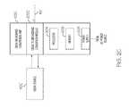
- FIG. 1A-1Bare block diagrams of exemplary embodiments of distributed base station radio systems 100 . Each of FIGS. 1A-1B illustrates a different embodiment of a distributed base station radio system 100 , labeled 100 A- 100 B respectively.
- FIG. 1Ais a block diagram of an exemplary embodiment of a distributed base station radio system 100 , distributed base station radio system 100 A.
- Distributed base station radio system 100 Aincludes at least one channelized broadband conversion unit 102 (including channelized broadband conversion unit 102 - 1 and any number of optional channelized broadband conversion units 102 through optional channelized broadband conversion unit 102 -A), at least one universal remote radio head 104 (including universal remote radio head 104 - 1 and any number of optional universal remote radio heads 104 through optional universal remote radio head 104 -B), a distributed base station radio switching network 106 , and optional other signal source interfaces 108 (including any number of optional other signal source interfaces 108 such as optional other signal source interface 108 - 1 through optional other signal source interface 108 -C).
- Each channelized broadband conversion unit 102is communicatively coupled to a channelized radio frequency source 110 that is configured to provide a channelized signal representing a single channel to be transported through the distributed base station radio system 100 A to the channelized broadband conversion unit 102 - 1 .
- each channelized broadband conversion unit 102is configured to receive a channelized signal representing a single channel from a corresponding channelized radio frequency source 110 .
- channelized broadband conversion unit 102 - 1is communicatively coupled to channelized radio frequency source 110 - 1 and optional channelized broadband conversion unit 102 -A is communicatively coupled to optional channelized radio frequency source 110 -A.
- Each channelized broadband conversion unit 102is also communicatively coupled to the distributed base station radio switching network 106 across a communication link 112 .
- channelized broadband conversion unit 102 - 1is communicatively coupled to the distributed base station radio switching network 106 across communication link 112 - 1
- optional channelized broadband conversion unit 102 -Ais communicatively coupled to the distributed base station radio switching network 106 across communication link 112 -A.
- each channelized broadband conversion unit 102is configured to convert a channelized signal from a corresponding channelized radio frequency source 110 into a downlink broadband signal and further configured to communicate the downlink broadband signal to the distributed base station radio switching network 106 (either directly or through other components of the distributed base station radio system 100 A) across a respective communication link 112 .
- Each downlink broadband signalcontains an individual channel that is positioned within a set of spectrum that reflects its location within the RF spectrum. Said another way, the channel in each downlink broadband signal is at a different RF frequency than the other channels to which it is being aggregated. Thus, when multiple downlink broadband signals are aggregated together, the individual channels do not overlap each other and all channels can be upconverted together to radio frequency spectrum simultaneously.
- each channelized broadband conversion unit 102is configured to receive uplink broadband signals across a respective communication link 112 from distributed base station radio switching network 106 .
- Each channelized broadband conversion unit 102is further configured to convert the received uplink broadband signal to a channelized signal for the corresponding channelized radio frequency source 110 and is further configured to communicate the channelized signal to the corresponding channelized radio frequency source 110 .
- the uplink broadband signalis an aggregate of the uplink broadband signals from at least one universal remote radio head 104 .
- the uplink broadband signalmay be an aggregate of the uplink broadband signals from any number of universal remote radio heads 104 .
- the communication links 112are optical fibers and the communication across the communication links 112 is optical. In these embodiments, an electrical to optical conversion occurs at the channelized broadband conversion units 102 .
- the communication links 112are conductive cables (such as coaxial cable, twisted pair, etc.) and the communication across the communication links 112 is electrical.
- the communication across the communication links 112is analog communication.
- the communication across the communication links 112is digital communication. In exemplary embodiments, any mixture of optical, electrical, analog, and digital communication occurs across the communication links 112 .
- a channelized broadband conversion unit 102may include functionality to convert between digital and analog signals.
- Distributed base station radio switching network 106communicatively couples the at least one channelized broadband conversion unit 102 and the optional other signal source interfaces 108 with the at least one universal remote radio head 104 .
- Distributed base station radio switching network 106may include one or more distributed base station radio switches or other components that functionally distributes downlink broadband signals from the at least one channelized broadband conversion unit 102 to the at least one universal remote radio head 104 .
- the distributed base station radio switching network 106aggregates downlink broadband signals from a plurality of channelized broadband conversion units 102 into a single aggregate downlink broadband signal that is routed to at least one universal remote radio head 104 .
- Distributed base station radio switching network 106also functionally distributes uplink broadband signals from the at least one universal remote radio head 104 to the at least one channelized broadband conversion unit 102 .
- the distributed base station radio switching network 106aggregates uplink broadband signals from a plurality of universal remote radio heads 104 into a single aggregate uplink broadband signal that is routed to at least one channelized broadband conversion unit 102 .
- the communication links 122 between the other signal source interfaces 108 and the distributed base station radio switching network 106are optical fibers and the communication across the communication links 122 are optical. In these embodiments, an electrical to optical conversion occurs at the other signal source interfaces 108 .
- the communication links 122are conductive cables (such as coaxial cable, twisted pair, etc.) and the communication across the communication links 122 is electrical.
- the communication across the communication links 122is analog communication.
- the communication across the communication links 122is digital communication. In exemplary embodiments, any mixture of optical, electrical, analog, and digital communication occurs across the communication links 122 .
- an other signal source interface 108may include functionality to convert between digital and analog signals.
- Each universal remote radio head 104is communicatively coupled to the distributed base station radio switching network 106 across a communication link 114 .
- universal remote radio head 104 - 1is communicatively coupled to the distributed base station radio switching network 106 across communication link 114 - 1
- optional universal remote radio head 104 -Bis communicatively coupled to the distributed base station radio switching network 106 across communication link 114 -B.
- Each universal remote radio head 104includes components configured for converting between at least one downlink broadband signal and at least one radio frequency band signal and at least one radio frequency antenna 116 configured to transmit and receive signals in the at least one radio frequency band to/from at least one subscriber unit 118 .
- the downlink broadband signalis an aggregate of multiple downlink broadband signals each with a channel positioned within a set of spectrum that reflects its location within the RF spectrum.
- the individual channelscan be converted to the at least one radio frequency band signals simultaneously.
- each universal remote radio head 104is configured to convert the at least one downlink broadband signal into a downlink radio frequency (RF) signal in a radio frequency band. In exemplary embodiments, this may include digital to analog converters and oscillators. Each universal remote radio head 104 is further configured to transmit the downlink radio frequency signal in the radio frequency band to at least one subscriber unit 118 using at least one radio frequency antenna 116 . In a specific exemplary embodiment, universal remote radio head 104 - 1 is configured to convert the at least one downlink broadband signal received from the distributed base station radio switching network 106 into a downlink radio frequency signal in a radio frequency band.
- RFradio frequency
- Universal remote radio head 104 - 1is further configured to transmit the downlink radio frequency signal in a radio frequency band using a radio frequency band antenna 116 - 1 to at least one subscriber unit 118 - 1 .
- universal remote radio head 104 - 1is configured to convert the at least one downlink broadband signal received from the distributed base station radio switching network 106 into a plurality of downlink radio frequency signals in a plurality of radio frequency bands.
- universal remote radio head 104 - 1is further configured to transmit the plurality of downlink radio frequency signals in the plurality of radio frequency bands using the radio frequency band antenna 116 - 1 and optional other radio frequency band antennas 116 through optional other radio frequency band antenna 116 -D.
- the universal remote radio head 104 - 1is configured to transmit one downlink radio frequency signal to one subscriber unit 118 - 1 using an antenna 116 - 1 and another radio frequency signal to one subscriber unit 118 -E using another antenna 116 -D.
- other combinations of radio frequency antennas 116 and other componentsare used to communicate other combinations of radio frequency signals in other various radio frequency bands to various subscriber units 118 , such as but not limited to using multiple antenna to communicate with a single subscriber unit 118 .
- each universal remote radio head 104is configured to receive uplink radio frequency signals from at least one subscriber unit 118 using at least one radio frequency antenna 116 .
- Each universal remote radio head 104is further configured to convert the radio frequency signals to at least one uplink broadband signal.
- Each universal remote radio head 104is further configured to aggregate the at least one uplink broadband signal into an aggregate uplink broadband signal and further configured to communicate the aggregate uplink broadband signal across at least one communication link 114 to the distributed base station radio switching network.
- universal remote radio heads 104multiplex uplink signals in different bands onto the same interface for communication to the next upstream element.
- each uplink broadband signalcontains a channel that is positioned within a set of spectrum that reflects its location within the RF spectrum.
- the individual channels themselves from the aggregated uplink broadband signalsdo not overlap each other when multiple uplink broadband signals are aggregated together.
- the communication links 114are optical fibers and the communication across the communication links 114 is optical. In these embodiments, an electrical to optical conversion occurs at the universal remote radio heads 104 .
- the communication links 114are conductive cables (such as coaxial cable, twisted pair, etc.) and the communication across the communication links 114 is electrical.
- the communication across the communication links 114is analog communication.
- the communication across the communication links 114is digital communication. In exemplary embodiments, any mixture of optical, electrical, analog, and digital communication occurs across the communication links 114 .
- a universal remote radio head 104may include functionality to convert between digital and analog signals.
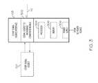
- FIG. 1Bis a block diagram of an exemplary embodiment of a distributed base station radio system 100 , distributed base station radio system 100 B.
- Distributed base station radio system 100 Bincludes at least one channelized broadband conversion unit 102 (including channelized broadband conversion unit 102 - 1 and any number of optional channelized broadband conversion units 102 through optional channelized broadband conversion unit 102 -A), at least one universal remote radio head 104 (including universal remote radio head 104 - 1 and any number of optional universal remote radio heads 104 through optional universal remote radio head 104 -B), a distributed base station radio switch 124 , and optional other signal source interfaces 108 (including any number of optional other signal source interfaces 108 such as optional other signal source interface 108 - 1 through optional other signal source interface 108 -C).
- Distributed base station radio system 100 Bincludes similar components to distributed base station radio system 100 A described above and operates according to similar principles and methods as distributed base station radio system 100 A described above. The difference between distributed base station radio system 100 B and distributed base station radio system 100 A is that the distributed base station radio switching network 106 is replaced with a single distributed base station radio switch 124 .
- Distributed base station radio switch 124communicatively couples the at least one channelized broadband conversion unit 102 and the optional other signal source interfaces 108 with the at least one universal remote radio head 104 .
- Distributed base station radio switch 124functionally distributes downlink broadband signals from the at least one channelized broadband conversion unit 102 to the at least one universal remote radio head 104 .
- the distributed base station radio switch 124aggregates downlink broadband signals from a plurality of channelized broadband conversion units 102 into a single aggregate downlink broadband signal that is routed to at least one universal remote radio head 104 .
- Distributed base station radio switch 124also functionally distributes uplink broadband signals from the at least one universal remote radio head 104 to the at least one channelized broadband conversion unit 102 and any optional channelized broadband conversion units 102 and/or optional other signal source interfaces 108 .
- the distributed base station radio switch 124aggregates uplink broadband signals from a plurality of universal remote radio heads 104 into a single aggregate uplink broadband signal that is routed to at least one channelized broadband conversion unit 102 .
- FIGS. 2A-2Care block diagrams of exemplary embodiments of channelized broadband conversion units 102 used in distributed base station radio systems, such as the exemplary distributed base station radio system 100 described above. Each of FIGS. 2A-2C illustrates a different embodiment of a type of base station network interface 102 , labeled 102 A- 102 C respectively.
- FIG. 2Ais a block diagram of an exemplary embodiment of a channelized broadband conversion unit 102 , channelized broadband conversion unit 102 A.
- Channelized broadband conversion unit 102 Aincludes channelized to broadband conversion module 202 A, an optional processor 204 , optional memory 206 , and an optional power supply 208 .
- channelized to broadband conversion module 202 Ais communicatively coupled to at least one channelized radio frequency source 110 .
- Channelized to broadband conversion module 202 Ais also communicatively coupled to at least one communication link 112 .
- the communication link 112is an optical communication link across a fiber optic cable, though it can also be other types of wired or wireless links in other embodiments.
- the channelized to broadband conversion module 202is implemented using optional processor 204 and optional memory 206 .
- the optional power supply 208provides power to the various elements of the channelized broadband conversion unit 102 A.
- channelized to broadband conversion module 202 Ais configured to receive a channelized downlink signal from the channelized radio frequency source 110 A.
- the channelized to broadband conversion module 202 Ais further configured to convert the channelized downlink signal to a downlink broadband signal.
- the channelized to broadband conversion module 202(or another additional component) further converts the downlink broadband signal from electrical signals to optical signals for output on an optical communication link 112 .
- the downlink broadband signalis transported using a conductive communication medium, such as coaxial cable or twisted pair, and the optical conversion is not necessary.
- the channelized to broadband conversion module 202 (or another additional component)further converts between digital and analog signals as required.
- channelized to broadband conversion module 202 Ais configured to receive an uplink broadband signal from communication link 112 .
- communication link 112is an optical medium
- the channelized to broadband conversion module 202 A(or another additional component) is configured to convert the uplink broadband signal between received optical signals and electrical signals.
- the uplink broadband signalis transported using a conductive communication medium, such as coaxial cable or twisted pair, and the optical conversion is not necessary.
- the channelized to broadband conversion module 202 (or another additional component)further converts between digital and analog signals as required.
- the channelized to broadband conversion module 202 Ais further configured to convert the uplink broadband signal to at least one uplink channelized signal.
- Channelized to broadband conversion module 202 Ais further configured to communicate the uplink channelized signals to the channelized radio frequency source 110 A.
- CPRI broadband conversion unit 102 Bis CPRI specific and includes the CPRI to broadband conversion module 202 B that is communicatively coupled to at least one Common Public Radio Interface (CPRI) source 110 B.
- CPRI broadband conversion unit 102 Bconverts between CPRI channelized signals and broadband signals.
- CPRI broadband conversion unit 102 Bconverts downlink CPRI channelized signals into a downlink broadband signal.
- CPRI broadband conversion unit 102 Bconverts an uplink broadband signal into uplink CPRI channelized signals.
- FIG. 2Cis a block diagram of an exemplary embodiment of a channelized broadband conversion unit 102 , Open Base Station Architecture Initiative (OBSAI) broadband conversion unit 102 C.
- OBSAI broadband conversion unit 102 Cincludes Open Base Station Architecture Initiative (OBSAI) to broadband conversion module 202 C, an optional processor 204 , optional memory 206 , and an optional power supply 208 .
- OBSAI broadband conversion unit 102 Cincludes similar components to channelized broadband conversion unit 102 A and operates according to similar principles and methods as channelized broadband conversion unit 102 A.
- signal source to broadband conversion module 302is configured to receive a downlink signal from the other signal source 120 .
- the signal source to broadband signal conversion module 302is further configured to convert the downlink signal to a downlink broadband signal.
- the signal source to broadband signal conversion module 302(or another additional component) is further configured to convert the downlink broadband signal from electrical signals to optical signals for output on an optical communication link 122 .
- the downlink broadband signalis transported using a conductive communication medium, such as coaxial cable or twisted pair, and the optical conversion is not necessary.
- the signal source to broadband signal conversion module 302 (or another additional component)further converts between digital and analog signals as required.
- signal source to broadband signal conversion module 302is configured to receive an uplink broadband signal from communication link 122 .
- the signal source to broadband signal conversion module 302(or another additional component) is configured to convert the uplink broadband signal between received optical signals and electrical signals.
- the uplink broadband signalis transported using a conductive communication medium, such as coaxial cable or twisted pair, and the optical conversion is not necessary.
- the signal source to broadband signal conversion module 302(or another additional component) further converts between digital and analog signals as required.
- the signal source to broadband signal conversion module 302is further configured to convert the uplink broadband signal to at least one uplink signal.
- Signal source to broadband signal conversion module 302is further configured to communicate the uplink signals to the other signal source 120 .
- FIGS. 4A-4Care block diagrams of exemplary embodiments of distributed base station radio switch 124 used in distributed base station radio systems, such as the exemplary distributed base station radio system 100 described above. Each of FIGS. 4A-4C illustrates a different embodiment of distributed base station radio system 100 , labeled distributed base station radio switch 124 A- 124 C respectively.
- FIG. 4Ais a block diagram of an exemplary distributed base station radio switch 124 A including a routing unit 402 , at least one electro-optical conversion module 404 - 1 (including electro-optical conversion module 404 - 1 and any amount of optional electro-optical conversion modules 404 through electro-optical conversion module 404 -A), at least one electro-optical conversion module 406 - 1 (including electro-optical conversion module 406 - 1 through optional electro-optical conversion module 406 -B), and optional electro-optical conversion modules 408 - 1 (including optional electro-optical conversion module 408 - 1 through optional electro-optical conversion module 408 -C).
- electro-optical conversion module 404 - 1including electro-optical conversion module 404 - 1 and any amount of optional electro-optical conversion modules 404 through electro-optical conversion module 404 -A
- at least one electro-optical conversion module 406 - 1including electro-optical conversion module 406 - 1 through optional electro-optical conversion module 406
- Each electro-optical conversion module 404is configured to convert the downlink broadband signal from optical to electrical signals, which are then passed onto the routing unit 402 .
- each electro-optical conversion module 404is configured to receive an uplink broadband signal in an electrical format from the routing unit 402 and to convert the uplink broadband signal to an optical format for communication across a communication link 112 to a channelized broadband conversion unit 102 .
- the electro-optical conversion module 404(or another additional component) further converts between digital and analog signals as required.
- this routingincludes separation of a single aggregate downlink broadband signal from a single electro-optical conversion module 404 into a plurality of downlink broadband signals that are passed to a plurality of electro-optical conversion modules 406 .
- the same or different downlink broadband signalsare routed to a plurality of electro-optical conversion modules 406 .
- the routing unit 402is configured to separate and route downlink broadband signals destined for a first subset of universal remote radio heads 104 from a first downlink aggregate broadband signal received from a single channelized broadband conversion unit 102 (such as channelized broadband conversion unit 102 - 1 ) and is further configured to separate and route downlink broadband signals destined for a second subset of universal remote radio heads 104 from a second downlink aggregate broadband signal received from a second channelized broadband conversion unit 102 (such as channelized broadband conversion unit 102 -A).
- the first and second subsetspartially overlap.
- the first and second subsetsare identical.
- downlink broadband signalsare destined to greater number of subsets of universal remote radio heads 104 .
- the routing unit 402receives at least one uplink broadband signal from at least one electro-optical conversion module 406 (such as electro-optical conversion module 406 - 1 ) from a universal remote radio head 104 and routes the at least one uplink broadband signal to at least one electro-optical conversion module 404 (such as electro-optical conversion module 404 - 1 ) for eventual communication to a channelized broadband conversion unit 102 .
- this routingincludes aggregation of a plurality of uplink broadband signals from a plurality of electro-optical conversion modules 406 into a single uplink broadband signal that is passed to at least one electro-optical conversion module 404 .
- the first and second subsetspartially overlap. In other exemplary embodiments, the first and second subsets are identical. In other exemplary embodiments, uplink broadband signals are aggregated and/or routed from a greater number of subsets of universal remote radio heads 104 .
- this routingincludes separation of a single aggregate uplink broadband signal from a single universal remote radio head 104 into a plurality of uplink broadband signals that are passed to a plurality of electro-optical conversion modules 404 and/or electro-optical conversion modules 208 - 1 .
- the same or different uplink broadband signalsare routed to a plurality of electro-optical conversion modules 404 .
- the routing unit 402is configured to separate and route uplink broadband signals destined for a first set of channelized broadband conversion units 102 from a first aggregate uplink broadband signal received from a single universal remote radio head 104 (such as universal remote radio head 104 - 1 ) and is further configured to separate and route uplink broadband signals destined for a second subset of channelized broadband conversion units 102 from a second aggregate uplink broadband signal received from a second universal remote radio head 104 (such as universal remote radio head 104 -B).
- the first and second subsetspartially overlap.
- the first and second subsetsare identical.
- uplink broadband signalsare destined to greater number of subsets of channelized broadband conversion units 102 and/or other signal source interfaces 108 .
- this routingincludes aggregation of a plurality of uplink broadband signals from a plurality of universal remote radio heads 104 via a plurality of electro-optical conversion modules 406 into a single aggregate uplink broadband signal that is passed to at least one channelized broadband conversion unit 102 through at least one electro-optical conversion module 404 .
- the same or different uplink aggregate broadband signalsare routed to a plurality of electro-optical conversion modules 406 .
- the routing unit 402is configured to aggregate and route uplink broadband signals from a first subset of universal remote radio heads 104 into a first uplink aggregate broadband signal that is transferred to at least a first channelized broadband conversion unit 102 - 1 via electro-optical conversion module 404 - 1 and communication link 112 - 1 and is further configured to aggregate and route uplink broadband signals from a second subset of universal remote radio heads 104 into a second uplink aggregate broadband signal that is transferred to at least a second channelized broadband conversion unit 102 -A via electro-optical conversion module 404 -A and communication link 112 -A.
- the first and second subsetspartially overlap.
- the first and second subsetsare identical.
- uplink broadband signals from a greater number of subsets of universal remote radio heads 104are aggregated and transferred to channelized broadband conversion units 102 and other signal source interfaces 108 .
- the electrical and optical signals communicated between the channelized broadband conversion units 102 , other signal source interfaces 108 , universal remote radio heads 104 , the distributed base station radio switch 124 A, and within the distributed base station radio switch 124 Acan be any combination of digital and analog signals. In exemplary embodiments, these electrical signals are digital signals. In other exemplary embodiments, these electrical signals are analog signals. In other exemplary embodiments, these electrical signals include a combination of digital and analog signals. In exemplary implementations, the communication between one or more channelized broadband conversion units 102 and the distributed base station radio switch 124 A is digital and the communication between the distributed base station radio switch 124 A and one or more universal remote radio heads 104 is analog.
- the communication between one or more channelized broadband conversion units 102 and the distributed base station radio switch 124 Ais analog and the communication between the distributed base station radio switch 124 A and one or more universal remote radio heads 104 is digital.
- the communication between a first subset of the channelized broadband conversion units 102 and/or other signal source interfaces 108 and the distributed base station radio switch 124 Ais digital and the communication between a second subset of the channelized broadband conversion units 102 and/or other signal source interfaces 108 and the distributed base station radio switch 124 A is analog.
- FIG. 4Bis a block diagram of an exemplary distributed base station radio switch 124 B including a routing unit 402 .
- the routing unit 402is implemented using optional processor 410 and memory 412 .
- Exemplary distributed base station radio switch 124 Bincludes similar components to distributed base station radio switch 124 A and operates according to similar principles and methods as distributed base station radio switch 124 A described above.
- the difference between distributed base station radio switch 124 B and distributed base station radio switch 124 Ais that distributed base station radio switch 124 B does not include any electro-optical conversion modules because the signals between the channelized broadband conversion units 102 , the other signal source interfaces 108 , and the universal remote radio heads 104 are communicated as electrical signals and not optical signals and do not need to be converted to and from optical signals.
- these electrical and optical signalscan be any combination of digital and analog signals.
- FIG. 4Cis a block diagram of an exemplary distributed base station radio switch 124 C including a routing unit 402 and at least one electro-optical conversion module 406 (including electro-optical conversion module 406 - 1 and any amount of optional electro-optical conversion modules 406 through electro-optical conversion module 406 -B).
- the routing unit 402 and/or some portion of the functionality of at least one electro-optical conversion module 406is implemented using optional processor 410 and memory 412 .
- Exemplary distributed base station radio switch 124 Cincludes similar components to distributed base station radio switch 124 A and operates according to similar principles and methods as distributed base station radio switch 124 A described above.
- distributed base station radio switch 124 Cdoes not include electro-optical conversion modules 404 between the channelized broadband conversion units 102 and the routing unit 402 or the other signal source interfaces 108 and the routing unit 402 because the signals between routing unit 402 , the channelized broadband conversion units 102 , and the other signal source interfaces 108 are communicated as electrical signals and are not optical signals and do not need to be converted to and from optical signals.
- these electrical and optical signalscan be any combination of digital and analog signals.
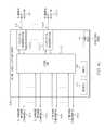
- FIG. 5is a block diagram of an exemplary embodiment of a universal remote radio head 104 used in a distributed base station radio system 100 .
- the universal remote radio head 104includes a multiplexing unit 502 , at least one radio frequency (RF) conversion module 504 - 1 (including RF conversion module 504 - 1 and any amount of optional RF conversion modules 504 through optional conversion module 504 -C), optional electro-optical conversion module 506 , optional Ethernet interface 508 , optional processor 510 , optional memory 512 , and optional power supply 514 .
- RFradio frequency
- multiplexing unit 502 , at least one RF conversion module 504 , optional electro-optical conversion module 506 , and/or optional Ethernet interface 508are implemented at least in part by optional processor 510 and memory 512 of universal remote radio head 104 .
- the optional power supply 514powers the various components of universal remote radio head 105 .
- the optional electro-optical conversion module 506is communicatively coupled to the universal remote radio head switching network 106 across a communication link 114 .
- the optional electro-optical conversion module 506is configured to receive a downlink broadband signal from the distributed base station radio switching network 106 and/or the distributed base station radio switch 124 across a communication link 114 .
- the optional electro-optical conversion module 506is configured to convert the downlink broadband signal from optical to electrical format, which is then passed onto the multiplexing unit 502 .
- the optional electro-optical conversion module 506is configured to receive an uplink broadband signal from the multiplexing unit 502 .
- the optional electro-optical conversion module 506is further configured to convert the uplink broadband signal from electrical to optical format, which is then passed onto the distributed base station radio switching network 106 and/or the distributed base station radio switch 124 across the communication link 114 .
- more than one electro-optical conversion module 506is coupled across more than one communication link 114 to the same distributed base station radio switch 124 , an intermediary device, and/or another distributed base station radio switch 124 .
- the signals communicated between the universal remote radio head 104 and the distributed base station radio switching network 106 and/or the distributed base station radio switch 124are electrical signals and do not require any conversion between optical and electrical.
- the electro-optical conversion module 506 (or another additional component)further converts between digital and analog signals as required.
- the multiplexing unit 502is communicatively coupled between the electro-optical conversion module 506 and/or the distributed base station radio switching network 106 and the at least one RF conversion module 504 and the optional Ethernet interface 508 .
- the multiplexing unit 502is configured to receive a downlink broadband signal from the distributed base station radio switching network 106 and/or a distributed base station radio switch 124 directly or via the optional electro-optical conversion module 506 .
- the multiplexing unit 502simulcasts the broadband signal to each RF conversion module 504 .
- the multiplexing unit 502splits apart individual downlink broadband signals from a downlink aggregate broadband signal and passes them to a plurality of RF conversion modules 504 .
- one of the downlink broadband signals communicated to one of the RF conversion modules 504pertains to a first mobile access band and/or technology while another downlink broadband signal communicated to another one of the RF conversion modules 504 pertains to a second mobile access band and/or technology.
- the multiplexing unit 502splits off a signal and communicates it to the Ethernet interface 508 .
- other types of dataare carried in the downlink broadband signals.
- the multiplexing unit 502is configured to receive upstream signals from various radio frequency (RF) conversion modules 504 and is further configured to multiplex a plurality of upstream signals into a single uplink broadband signal.
- the multiplexing unit 502is configured to aggregate a plurality of upstream signals from various radio frequency (RF) conversion modules 504 into a single uplink broadband signal.
- the multiplexing unit 502is further configured to communicate the uplink broadband signal to distributed base station radio switching network 106 and/or the distributed base station radio switch 124 directly or via the optional electro-optical conversion module 506 .
- Each RF conversion module 504is communicatively coupled to the multiplexing unit 502 and is coupled to and/or includes at least one antenna 116 .
- Each RF conversion module 504is configured to convert between at least one downlink broadband signal and radio frequency signals in at least one radio frequency band.
- Each RF conversion moduleis configured to communicate radio frequency signals in the at least one radio frequency band across an air medium with at least one subscriber using at least one antenna 116 .
- each RF conversion module 504is configured to convert at least one downlink signal into a downlink radio frequency (RF) signal in a radio frequency band. In exemplary embodiments, this may include digital to analog converters and oscillators. Each RF conversion module 504 is further configured to transmit the downlink radio frequency signals in the radio frequency band to at least one subscriber unit 118 using at least one antenna 116 . In a specific embodiment, radio frequency conversion module 504 - 1 is configured to convert at least one downlink broadband signal into a downlink radio frequency signal in a radio frequency band. Each RF conversion module 504 is further configured to transmit the downlink radio frequency signal in a radio frequency band using a radio frequency antenna 116 - 1 to at least one wireless subscriber unit.
- RFradio frequency
- radio frequency conversion module 504 - 1is configured to convert a first downlink signal into a first downlink radio frequency signal in a first radio frequency band and to transmit the first downlink radio frequency signal in the first radio frequency band to at least one wireless subscriber using the antenna 116 - 1 .
- radio frequency conversion module 504 - 2is configured to convert a second downlink broadband signal into a second downlink radio frequency signal in a second radio frequency band and to transmit the second downlink radio frequency signal in the second radio frequency band to at least one wireless subscriber unit 118 using the antenna 116 - 2 .
- one radio frequency conversion module 504 - 1 and antenna 116 - 1 pairtransports to a first set of wireless subscriber units 118 in a first band and another radio frequency conversion module 504 -C and antenna 116 -C pair transports to a second set of wireless subscriber units 118 in a second band.
- Other combinations of radio frequency conversion module 504 and antenna 116 pairsare used to communicate other combinations of radio frequency signals in other various radio frequency bands to various subscriber units 118 , such as but not limited to MIMO or carrier aggregation where signals from multiple antennas go to a single subscriber unit 118 .
- each RF conversion module 504is configured to receive uplink radio frequency signals from at least one subscriber unit 118 using at least one radio frequency antenna 116 .
- Each radio frequency conversion module 504is further configured to convert the radio frequency signals to at least one uplink broadband signal.
- Each radio frequency conversion module 504is further configured to communicate the uplink broadband signal to the broadband signal multiplexing unit 502 .
- FIGS. 6A-6Eare block diagrams of exemplary embodiments of radio frequency (RF) conversion modules of remote antenna units 106 used in distributed antenna systems, such as exemplary distributed antenna system 100 described above. Each of FIGS. 6A-6E illustrates a different embodiment of RF conversion module 504 , labeled RF conversion module 504 A- 504 E respectively.
- RFradio frequency
- FIG. 6Ais a block diagram of an exemplary RF conversion module 504 A including an optional signal stream conditioner 602 , an RF frequency converter 604 , an optional RF conditioner 606 , and an RF duplexer 608 coupled to a single antenna 116 .
- the optional signal conditioner 602is communicatively coupled to a multiplexing unit 502 and the radio frequency (RF) converter 604 .
- the optional signal conditioner 602conditions the downlink broadband signal (for example, through amplification, attenuation, and filtering) received from the remote multiplexing unit 502 and passes the downlink signal to the RF converter 604 .
- the optional signal conditioner 602conditions the uplink broadband signal (for example, through amplification, attenuation, and filtering) received from the RF converter 604 and passes the uplink broadband signal to the remote multiplexing unit 502 .
- the RF converter 604is communicatively coupled to either the multiplexing unit 502 or the optional signal conditioner 602 on one side and to either RF duplexer 608 or the optional RF conditioner 606 on the other side.
- the RF converter 604converts a downlink broadband signal to downlink radio frequency (RF) signals and passes the downlink RF signals onto either the RF duplexer 608 or the optional RF conditioner 606 .
- the RF converter 604converts uplink radio frequency (RF) signals received from either the RF duplexer 608 or the optional RF conditioner 606 to an uplink broadband signal and passes the uplink broadband signal to either the multiplexing unit 502 or the optional signal conditioner 602 .
- RFradio frequency
- the optional RF conditioner 606is communicatively coupled between the RF converter 604 and the RF duplexer 608 .
- the RF conditioner 606performs gain adjustment and filtering on the downstream and upstream RF signals.
- the RF duplexer 608is communicatively coupled to either the RF frequency converter 604 or the optional RF conditioner 606 on one side and the antenna 116 on the other side.
- the RF duplexer 608duplexes the downlink RF signals with the uplink RF signals for transmission/reception using the antenna 116 .
- FIG. 6Bis a block diagram of an exemplary RF conversion module 504 B including an optional signal conditioner 602 , an RF frequency converter 604 , an optional RF conditioner 606 coupled to a downlink antenna 116 A and an uplink antenna 116 B.
- RF conversion module 504 Bincludes similar components to RF conversion module 504 A and operates according to similar principles and methods as RF conversion module 504 A described above. The difference between RF conversion module 504 B and RF conversion module 504 A is that RF conversion module 504 B does not include RF duplexer 608 and instead includes separate downlink antenna 116 A used to transmit RF signals to at least one subscriber unit 118 and uplink antenna 116 B used to receive RF signals from at least one subscriber unit 118 .
- FIG. 6Cis a block diagram of an exemplary RF conversion module 504 C- 1 and exemplary RF conversion module 504 C- 2 that share a single antenna 116 through an RF diplexer 610 .
- the RF conversion module 504 C- 1includes an optional signal conditioner 602 - 1 an RF frequency converter 604 - 1 , an optional RF conditioner 606 - 1 , and an RF duplexer 608 - 1 communicatively coupled to RF diplexer 610 that is communicatively coupled to antenna 116 .
- the RF conversion module 504 C- 2includes an optional signal conditioner 602 - 2 , an RF frequency converter 604 - 2 , an optional RF conditioner 606 - 2 , and an RF duplexer 608 - 2 communicatively coupled to RF diplexer 610 that is communicatively coupled to antenna 116 .
- Each of RF conversion module 504 C- 1 and 504 C- 2operate according to similar principles and methods as RF conversion module 504 A described above.
- the difference between RF conversion modules 504 C- 1 and 504 C- 2 and RF conversion module 504 Ais that RF conversion modules 504 C- 1 and 504 C- 2 are both coupled to a single antenna 116 through RF diplexer 610 .
- the RF diplexer 610diplexes the duplexed downlink and uplink signals for both RF conversion module 504 C- 1 and 504 C- 2 for transmission/reception using the single antenna 116 .
- FIG. 6Dis a block diagram of an exemplary RF conversion module 504 D including an optional signal conditioner 602 , an RF frequency converter 604 , an optional RF conditioner 606 , and a time division duplexing (TDD) switch 612 coupled to an antenna 116 .
- RF conversion module 504 Dincludes similar components to RF conversion module 504 A and operates according to similar principles and methods as RF conversion module 504 A described above. The difference between RF conversion module 504 D and RF conversion module 504 A is that RF conversion module 504 D does not include RF duplexer 608 and instead includes the TDD switch 612 that allows the RF conversion module 504 D to switch between transmit and receive modes at different times based on a TDD signal that can be supplied from other components in the system.
- TDDtime division duplexing
- FIG. 6Eis a block diagram of an exemplary RF conversion module 504 E- 1 and exemplary RF conversion module 504 E- 2 that share a single antenna 116 through an RF diplexer 610 .
- the RF conversion module 504 E- 1includes an optional signal conditioner 602 - 1 , an RF frequency converter 604 - 1 , an optional RF conditioner 606 - 1 , and a TDD switch 612 - 1 communicatively coupled to RF diplexer 610 that is communicatively coupled to antenna 116 .
- the RF conversion module 504 E- 2includes an optional signal conditioner 602 - 2 , an RF frequency converter 604 - 2 , an optional RF conditioner 606 - 2 , and a TDD switch 612 - 2 communicatively coupled to RF diplexer 610 that is communicatively coupled to antenna 116 .
- Each of RF conversion module 504 E- 1 and 504 E- 2operate according to similar principles and methods as RF conversion modules 504 C- 1 and 504 C- 2 described above.
- RF conversion modules 504 E- 1 and 504 E- 2do not include RF duplexers 608 - 1 and 608 - 2 and instead include TDD switches 612 - 1 and 612 - 2 that allow the RF conversion modules 504 E- 1 and 504 E- 2 to switch between transmit and receive modes based on TDD signals that can be supplied from other components in the system.
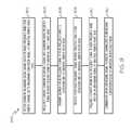
- FIG. 7is a flow diagram illustrating an exemplary embodiment of a method 700 of operating a distributed base station radio system.
- Exemplary method 700begins at block 702 with receiving a first downlink channelized signal for a first radio frequency band from a first channelized radio frequency source at a first channelized to broadband conversion unit.
- the channelized radio frequency sourceis a base band unit of a wireless access base station.
- the first channelized radio frequency sourceis at least one of a Common Public Radio Interface (CPRI) base station interface and an Open Base Station Architecture Initiative (OBSAI) base station interface.
- CPRICommon Public Radio Interface
- OBSAIOpen Base Station Architecture Initiative
- the first downlink channelized datais formatted according to at least one of a Common Public Radio Interface (CPRI) standard and an Open Base Station Architecture Initiative (OBSAI) standard.
- CPRICommon Public Radio Interface
- OBSAIOpen Base Station Architecture Initiative
- Exemplary method 700proceeds to block 704 with converting the first downlink channelized signal into a first downlink broadband signal at the first channelized to broadband conversion unit.
- Exemplary method 700proceeds to block 706 with communicating the first downlink broadband signal to a first universal remote radio head from the first channelized to broadband conversion unit 706 .
- Exemplary method 700proceeds to block 708 with frequency converting the first downlink broadband signal into a first downlink radio frequency signal at the first universal remote radio head.
- Exemplary method 700proceeds to block 710 with transmitting a first downlink radio frequency signal in the first radio frequency band to a first subscriber unit at the first universal remote radio head.
- the method 700further includes receiving second downlink channelized data for a second radio frequency band from a second channelized radio frequency source at a second channelized to broadband conversion unit.
- the method 700further includes receiving the first downlink broadband signal from the first channelized to broadband conversion unit at a switch; receiving the second downlink broadband signal from the second channelized to broadband conversion unit at the switch; aggregating the first downlink broadband signal with the second downlink broadband signal into an aggregate downlink broadband signal; and communicating the aggregate downlink broadband signal from the switch to the first universal remote radio head.
- the method 700further includes extracting the first downlink broadband signal from the aggregate downlink broadband signal at the first universal remote radio head.
- the method 700further includes receiving second downlink channelized data for a second radio frequency band from a second channelized radio frequency source at a second channelized to broadband conversion unit; converting the second downlink channelized data into a second downlink broadband signal; communicating the second downlink broadband signal to the first universal remote radio head from the second channelized to broadband conversion unit; frequency converting the second downlink broadband signal into second downlink radio frequency signals in the second radio frequency band at the first universal remote radio head; and transmitting the second downlink radio frequency signals in the second radio frequency band to at least one subscriber unit at the first universal remote radio head.
- frequency converting the first downlink broadband signal into first downlink radio frequency signals in the first radio frequency bandoccurs at a first frequency converter of the first universal remote radio head; frequency converting the second downlink broadband signal into second downlink radio frequency signals in the second radio frequency band occurs at a second frequency converter of the first universal remote radio head; transmitting the first downlink radio frequency signals in the first radio frequency band to a first subscriber unit at the first universal remote radio head occurs at a first power amplifier, radio frequency transceiver, and antenna set of the first universal remote radio head; and transmitting the second downlink radio frequency signals in the second radio frequency band to at least one subscriber unit at the first universal remote radio head occurs at a second power amplifier, radio frequency transceiver, and antenna set of the first universal remote radio head.
- frequency converting the first downlink broadband signal into first downlink radio frequency signals in the first radio frequency bandoccurs at a first frequency converter of the first universal remote radio head; frequency converting the second downlink broadband signal into second downlink radio frequency signals in the second radio frequency band occurs at a second frequency converter of the first universal remote radio head; and transmitting both the first downlink radio frequency signals in the first radio frequency band and the second downlink radio frequency signals in the second radio frequency band occurs at a single power amplifier, radio frequency transceiver, and antenna set.
- frequency converting both the first downlink broadband signal into the first downlink radio frequency signals in the first radio frequency band and the second downlink broadband signals into the second downlink radio frequency signals in the second radio frequency bandoccurs at a single radio frequency converter; and transmitting both the first downlink radio frequency signals in the first radio frequency band and the second downlink radio frequency signals in the second radio frequency band occurs at a single power amplifier, radio frequency transceiver, and antenna set.
- the method 700further includes receiving second downlink channelized data for a second radio frequency band from a second channelized radio frequency source at a second channelized to broadband conversion unit; converting the second downlink channelized data into a second downlink broadband signal; communicating the second downlink broadband signal to a second universal remote radio head from the second channelized to broadband conversion unit; frequency converting the second downlink broadband signal into second downlink radio frequency signals in the second radio frequency band at the second universal remote radio head; and transmitting the second downlink radio frequency signals in the second radio frequency band to at least one subscriber unit at the second universal remote radio head.
- FIG. 8is a flow diagram illustrating an exemplary embodiment of a method 800 of operating a distributed base station radio system.
- Exemplary method 800begins at block 802 with receiving a first uplink radio frequency signal in a first radio frequency band from a first subscriber unit at a first universal remote radio head.
- Exemplary method 800proceeds to block 804 with frequency converting the first uplink radio frequency signal in the first radio frequency band into a first uplink broadband signal at a first universal remote radio head 804 .
- Exemplary method 800proceeds to block 806 with communicating the first uplink broadband signal to a first channelized to broadband conversion unit from the first universal remote radio head.
- Exemplary method 800proceeds to block 808 with converting the first uplink broadband signal into a first uplink channelized signal for the first radio frequency band at the first channelized to broadband conversion unit 808 .
- Exemplary method 800proceeds to block 810 with communicating the first uplink channelized signal for the first radio frequency band to the first channelized radio frequency source at the first channelized to broadband conversion unit.
- Exemplary method 900proceeds to block 910 with frequency converting the uplink radio frequency signal in the radio frequency band into an uplink broadband signal at the universal remote radio head.
- Exemplary method 900proceeds to block 912 with communicating the uplink broadband signal to the remote channelized to broadband conversion module at the universal remote radio head.
- the first downlink channelized datais formatted according to at least one of a Common Public Radio Interface (CPRI) standard, an Open Base Station Architecture Initiative (OBSAI) standard, and a Open Radio Interface (ORI) standard.
- CPRICommon Public Radio Interface
- OBSAIOpen Base Station Architecture Initiative
- ORIOpen Radio Interface
- Exemplary method 1000proceeds to block 1004 with converting the downlink channelized signal into a downlink broadband signal at the channelized to broadband conversion unit.
- Exemplary method 1000proceeds to block 1006 with communicating the downlink broadband signal to a universal remote radio head at the channelized to broadband conversion unit.
- Exemplary method 1000proceeds to block 1008 with receiving an uplink broadband signal from the universal remote radio head at the channelized to broadband conversion unit.
- Exemplary method 1000proceeds to block 1010 with converting the uplink broadband signal into an uplink channelized signal for the radio frequency band at the channelized to broadband conversion unit.
- Exemplary method 1000proceeds to block 1012 with communicating the uplink channelized signal to the channelized radio frequency source at the channelized to broadband conversion unit.
- Embodiments of processors described hereininclude or function with software programs, firmware or other computer readable instructions for carrying out various methods, process tasks, calculations, and control functions, used in the components of the systems described above.
- the computer readable mediumcan be implemented as any available media that can be accessed by a general purpose or special purpose computer or processor, or any programmable logic device.
- Suitable processor-readable mediamay include storage or memory media such as magnetic or optical media.
- storage or memory mediamay include conventional hard disks, Compact Disk-Read Only Memory (CD-ROM), volatile or non-volatile media such as Random Access Memory (RAM) (including, but not limited to, Synchronous Dynamic Random Access Memory (SDRAM), Double Data Rate (DDR) RAM, RAMBUS Dynamic RAM (RDRAM), Static RAM (SRAM), etc.), Read Only Memory (ROM), Electrically Erasable Programmable ROM (EEPROM), and flash memory, etc.
- RAMRandom Access Memory
- SDRAMSynchronous Dynamic Random Access Memory
- DDRDouble Data Rate
- RDRAMRAMBUS Dynamic RAM
- SRAMStatic RAM
- ROMRead Only Memory
- EEPROMElectrically Erasable Programmable ROM
- flash memoryetc.
- Suitable processor-readable mediamay also include transmission media such as electrical, electromagnetic, or digital signals, conveyed via a communication medium such as a network and/or a wireless link.
- Example 1includes a distributed base station radio system comprising: a first channelized to broadband conversion unit configured to receive first downlink channelized data for a first radio frequency band from a first channelized radio frequency source; wherein the first channelized to broadband conversion unit is further configured to convert the first downlink channelized data into a first downlink broadband signal; a first universal remote radio head communicatively coupled to the first channelized to broadband conversion unit; wherein the first channelized to broadband conversion unit is further configured to communicate the first downlink broadband signal to the first universal remote radio head; wherein the first universal remote radio head is configured to receive the first downlink broadband signal; wherein the first universal remote radio head is further configured to frequency convert the first downlink broadband signal into first downlink radio frequency signals in the first radio frequency band; wherein the first universal remote radio head is further configured to transmit the first downlink radio frequency signals in the first radio frequency band to a first subscriber unit.
- Example 2includes the distributed base station radio system of Example 1, wherein the first channelized radio frequency source is at least one of a Common Public Radio Interface (CPRI) base station interface, an Open Base Station Architecture Initiative (OBSAI) base station interface, and an Open Radio Interface (ORI) interface; and wherein the first downlink channelized data is formatted according to at least one of a Common Public Radio Interface (CPRI) standard, an Open Base Station Architecture Initiative (OBSAI) standard, and an Open Radio Interface (ORI) standard.
- CPRICommon Public Radio Interface
- OBSAIOpen Base Station Architecture Initiative
- ORIOpen Radio Interface
- Example 3includes the distributed base station radio system of any of Examples 1-2, wherein the first universal remote radio head is further communicatively coupled to a second channelized to broadband conversion unit configured to receive second downlink channelized data for a second radio frequency band from a second channelized radio frequency source; wherein the second channelized to broadband conversion unit is further configured to convert the second downlink channelized data for the second radio frequency band into a second downlink broadband signal; and wherein the second channelized to broadband conversion unit is further configured to communicate the second downlink broadband signal to the first universal remote radio head.
- a second channelized to broadband conversion unitconfigured to receive second downlink channelized data for a second radio frequency band from a second channelized radio frequency source
- the second channelized to broadband conversion unitis further configured to convert the second downlink channelized data for the second radio frequency band into a second downlink broadband signal
- the second channelized to broadband conversion unitis further configured to communicate the second downlink broadband signal to the first universal remote radio head.
- Example 4includes the distributed base station radio system of Example 3, further comprising: a switch communicatively coupled between both the first channelized to broadband conversion unit and the second channelized to broadband conversion unit and the first universal remote radio head, the switch configured to receive the first downlink broadband signal from the first channelized to broadband conversion unit and the second downlink broadband signal from the second channelized to broadband conversion unit and to aggregate the first downlink broadband signal with the second downlink broadband signal into an aggregate downlink broadband signal; the switch further configured to transmit the aggregate downlink broadband signal to the first universal remote radio head; the first universal remote radio head further configured to receive the aggregate downlink broadband signal and to frequency convert the aggregate downlink broadband signal into radio frequency signals in both the first radio frequency band and the second radio frequency band; and the first universal remote radio head further configured to transmit the radio frequency signals in both the first radio frequency band and the second radio frequency band to at least one subscriber unit.
- a switchcommunicatively coupled between both the first channelized to broadband conversion unit and the second channelized to broadband conversion unit and the first universal remote radio head, the switch configured to receive the
- Example 5includes the distributed base station radio system of Example 4, wherein the switch is configured to aggregate the first downlink broadband signal with the second downlink broadband signal through at least one of summing, multiplexing, and combining.
- Example 6includes the distributed base station radio system of any of Examples 4-5, wherein the switch is further configured to transmit the aggregate downlink broadband signal to a second universal remote radio head; wherein the second universal remote radio is configured to receive the aggregate downlink broadband signal and to frequency convert the aggregate downlink broadband signal into radio frequency signals in both the first radio frequency band and the second radio frequency band; and wherein the second universal remote radio head is further configured to transmit the radio frequency signals in the first radio frequency band and the second radio frequency band to at least one subscriber unit.
- Example 7includes the distributed base station radio system of any of Examples 3-6, further comprising: a switch communicatively coupled between both the first channelized to broadband conversion unit and the second channelized to broadband conversion unit and the first universal remote radio head, the switch configured to receive the first downlink broadband signal from the first channelized to broadband conversion unit and the second downlink broadband signal from the second channelized to broadband conversion unit and to aggregate the first downlink broadband signal with the second downlink broadband signal into an aggregate downlink broadband signal; the switch further configured to transmit the aggregate downlink broadband signal to the first universal remote radio head; the first universal remote radio head further configured to receive the aggregate downlink broadband signal, to extract the first downlink broadband signal from the aggregate downlink broadband signal, and to frequency convert the first downlink broadband signal into radio frequency signals in the first radio frequency band; the first universal remote radio head further configured to transmit the first radio frequency signals in the first radio frequency band to at least one subscriber unit.
- a switchcommunicatively coupled between both the first channelized to broadband conversion unit and the second channelized to broadband conversion unit and the first universal remote radio head
- Example 8includes the distributed base station radio system of Example 7, wherein the first universal remote radio head is configured to extract the first downlink broadband signal from the aggregate downlink broadband signal through at least one of de-multiplexing and splitting apart.
- Example 9includes the distributed base station radio system of any of Examples 1-8, wherein the first universal remote radio head is further communicatively coupled to a second channelized to broadband conversion unit configured to receive second downlink channelized data for a second radio frequency band from a second channelized radio frequency source; wherein the second channelized to broadband conversion unit is further configured to convert the second downlink channelized data into a second downlink broadband signal; wherein the second channelized to broadband conversion unit is further configured to communicate the second downlink broadband signal to the first universal remote radio head; wherein the first universal remote radio head is further configured to receive the second downlink broadband signal; wherein the first universal remote radio head is further configured to frequency convert the second downlink broadband signal into second downlink radio frequency signals in the second radio frequency band; and wherein the first universal remote radio head is further configured to transmit the second downlink radio frequency signals in the second radio frequency band to at least one subscriber unit.
- the first universal remote radio headis further communicatively coupled to a second channelized to broadband conversion unit configured to receive second downlink channelized data for a second
- Example 10includes the distributed base station radio system of Example 9, wherein the first universal remote radio head includes a first radio frequency converter configured to frequency convert the first downlink broadband signal into the first downlink radio frequency signals in the first radio frequency band; wherein the first universal remote radio head includes a second radio frequency converter configured to frequency convert the second downlink broadband signal into the second downlink radio frequency signals; wherein the first universal remote radio head includes a first power amplifier, radio frequency transceiver, and antenna set configured to transmit the first radio frequency band; and wherein the first universal remote radio head includes a second power amplifier, radio frequency transceiver, and antenna set configured to transmit the second radio frequency band.
- Example 11includes the distributed base station radio system of Example 10, wherein the first downlink radio frequency signals and the second downlink radio frequency signals are MIMO signals transmitted to a single subscriber unit.
- Example 12includes the distributed base station radio system of any of Examples 7-11, wherein the first universal remote radio head includes a first radio frequency converter configured to frequency convert the first downlink broadband signal into the first downlink radio frequency signals in the first radio frequency band; wherein the first universal remote radio head includes a second radio frequency converter configured to frequency convert the second downlink broadband signal into the second downlink radio frequency signals in the second radio frequency band; and wherein the first universal remote radio head includes a single power amplifier, radio frequency transceiver, and antenna set configured to transmit both the first radio frequency band and the second radio frequency band.
- the first universal remote radio headincludes a first radio frequency converter configured to frequency convert the first downlink broadband signal into the first downlink radio frequency signals in the first radio frequency band
- the first universal remote radio headincludes a second radio frequency converter configured to frequency convert the second downlink broadband signal into the second downlink radio frequency signals in the second radio frequency band
- the first universal remote radio headincludes a single power amplifier, radio frequency transceiver, and antenna set configured to transmit both the first radio frequency band and the second radio
- Example 13includes the distributed base station radio system of any of Examples 7-12, wherein the first universal remote radio head includes a single radio frequency converter configured to frequency convert both the first downlink broadband signal into the first downlink radio frequency signals in the first radio frequency band and the second downlink broadband signal into the second downlink radio frequency signals in the second radio frequency band; and wherein the first universal remote radio head includes a single power amplifier, radio frequency transceiver, and antenna set configured to transmit both the first radio frequency band and the second radio frequency band.
- the first universal remote radio headincludes a single radio frequency converter configured to frequency convert both the first downlink broadband signal into the first downlink radio frequency signals in the first radio frequency band and the second downlink broadband signal into the second downlink radio frequency signals in the second radio frequency band
- the first universal remote radio headincludes a single power amplifier, radio frequency transceiver, and antenna set configured to transmit both the first radio frequency band and the second radio frequency band.
- Example 14includes the distributed base station radio system of any of Examples 1-13, further comprising: a second channelized to broadband conversion unit configured to receive second downlink channelized data for a second radio frequency band from a second channelized radio frequency source; wherein the second channelized to broadband conversion unit is further configured to convert the second downlink channelized data into a second downlink broadband signal; a second universal remote radio head communicatively coupled to the second channelized to broadband conversion unit; a switch communicatively coupled between both the first channelized to broadband conversion unit and the second channelized to broadband conversion unit and the first universal remote radio head and the second universal remote radio head; wherein the first channelized to broadband conversion unit is further configured to communicate the first downlink broadband signal to the switch; wherein the second channelized to broadband conversion unit is further configured to communicate the second downlink broadband signal to the switch; wherein the switch is configured to communicate the first downlink broadband signal to the first universal remote radio head; wherein the switch is configured to communicate the second downlink broadband signal to the second universal remote radio head; wherein the second universal remote radio head is configured
- Example 15includes the distributed base station radio system of any of Examples 1-14, wherein the first channelized radio frequency source is a base band unit of a wireless access base station.
- Example 16includes the distributed base station radio system of any of Examples 1-15, further comprising: wherein the first universal remote radio head is further configured to receive uplink radio frequency signals in the first radio frequency band from the first subscriber unit; wherein the first universal remote radio head is further configured to frequency convert the uplink radio frequency signals in the first radio frequency band into an uplink broadband signal; wherein the first universal remote radio head is further configured to communicate the uplink broadband signal to the first channelized to broadband conversion unit; wherein the first channelized to broadband conversion unit is further configured to receive the uplink broadband signal; wherein the first channelized to broadband conversion unit is further configured to convert the uplink broadband signal into uplink channelized data for the first radio frequency band; and wherein the first channelized to broadband conversion unit is further configured to communicate the uplink channelized data for the first radio frequency band to the first channelized radio frequency source.
- Example 17includes the distributed base station radio system of Example 16, wherein downlink and uplink signals within the first radio frequency band are in distinct spectrum.
- Example 18includes the distributed base station radio system of any of Examples 16-17, wherein downlink and uplink signals within the first radio frequency band overlap in spectrum.
- Example 19includes the distributed base station radio system of any of Examples 16-18, wherein the downlink and uplink signals within the first radio frequency band are separated in time using a Time Division Duplexing (TDD) scheme.
- TDDTime Division Duplexing
- Example 20includes a method comprising: receiving first downlink channelized data for a first radio frequency band from a first channelized radio frequency source at a first channelized to broadband conversion unit; converting the first downlink channelized data into a first downlink broadband signal at the first channelized to broadband conversion unit; communicating the first downlink broadband signal to a first universal remote radio head from the first channelized to broadband conversion unit; frequency converting the first downlink broadband signal into first downlink radio frequency signals in the first radio frequency band at the first universal remote radio head; and transmitting the first downlink radio frequency signals in the first radio frequency band to a first subscriber unit at the first universal remote radio head.
- Example 21includes the method of Example 20, wherein the first channelized radio frequency source is at least one of a Common Public Radio Interface (CPRI) base station interface, an Open Base Station Architecture Initiative (OBSAI) base station interface, and an Open Radio Interface (ORI) interface; and wherein the first downlink channelized data is formatted according to at least one of a Common Public Radio Interface (CPRI) standard, an Open Base Station Architecture Initiative (OBSAI) standard, and an Open Radio Interface (ORI) standard.
- CPRICommon Public Radio Interface
- OBSAIOpen Base Station Architecture Initiative
- ORIOpen Radio Interface
- Example 22includes the method of any of Examples 20-21, further comprising: receiving second downlink channelized data for a second radio frequency band from a second channelized radio frequency source at a second channelized to broadband conversion unit; convert the second downlink channelized data for the second radio frequency band into a second downlink broadband signal at the second channelized to broadband conversion unit; communicating the second downlink broadband signal from the second channelized to broadband conversion unit to the first universal remote radio head; frequency converting the second downlink broadband signal into radio frequency signals in the second radio frequency band; and transmitting the radio frequency signals in the second radio frequency band to at least one subscriber unit at the first universal remote radio head.
- Example 23includes the method of Example 22, further comprising: receiving the first downlink broadband signal from the first channelized to broadband conversion unit at a switch; receiving the second downlink broadband signal from the second channelized to broadband conversion unit at the switch; aggregating the first downlink broadband signal with the second downlink broadband signal into an aggregate downlink broadband signal at the switch; and communicating the aggregate downlink broadband signal from the switch to the first universal remote radio head.
- Example 24includes the method of Example 23, wherein aggregating the first downlink broadband signal with the second downlink broadband signal into an aggregate downlink broadband signal at the switch includes at least one of summing, multiplexing, and combining the first downlink broadband signal with the second downlink broadband signal.
- Example 25includes the method of any of Examples 23-24, further comprising: communicating the aggregate downlink broadband signal from the switch to a second universal remote radio head; converting the aggregate downlink broadband signal into radio frequency signals in both the first radio frequency band and the second radio frequency band at the second universal remote radio head; and transmitting the radio frequency signals in both the first radio frequency band and the second radio frequency band at the second universal remote radio head.
- Example 26includes the method of any of Examples 23-25, further comprising: communicating the aggregate downlink broadband signal from the switch to a second universal remote radio head; extracting the second downlink broadband signals from the aggregate downlink broadband signal; converting the second downlink broadband signal into second downlink radio frequency signals in the second radio frequency band at the second universal remote radio head; and transmitting the second downlink radio frequency signals in the second radio frequency band at the second universal remote radio head.
- Example 27includes the method of Example 26, wherein extracting the second downlink broadband signals from the aggregate downlink broadband signal includes at least one of de-multiplexing and splitting apart.
- Example 28includes the method of any of Examples 22-27, further comprising: receiving the first downlink broadband signal from the first channelized to broadband conversion unit at a switch; receiving the second downlink broadband signal from the second channelized to broadband conversion unit at the switch; aggregating the first downlink broadband signal with the second downlink broadband signals into an aggregate downlink broadband signal at the switch; communicating the aggregate downlink broadband signal from the switch to the first universal remote radio head; frequency converting the aggregate downlink broadband signal into radio frequency signals in both the first radio frequency band and the second radio frequency band; and transmitting the radio frequency signals in both the first radio frequency band and the second radio frequency band to at least one subscriber unit at the first universal remote radio head.
- Example 29includes the method of any of Examples 20-28, further comprising: receiving second downlink channelized data for a second radio frequency band from a second channelized radio frequency source at a second channelized to broadband conversion unit; converting the second downlink channelized data into a second downlink broadband signal; communicating the second downlink broadband signal to the first universal remote radio head from the second channelized to broadband conversion unit; frequency converting the second downlink broadband signal into second downlink radio frequency signals in the second radio frequency band at the first universal remote radio head; and transmitting the second downlink radio frequency signals in the second radio frequency band to at least one subscriber unit.
- Example 30includes the method of Example 29, wherein frequency converting the first downlink broadband signal into first downlink radio frequency signals in the first radio frequency band occurs at a first frequency converter of the first universal remote radio head; wherein frequency converting the second downlink broadband signal into second downlink radio frequency signals in the second radio frequency band occurs at a second frequency converter of the first universal remote radio head; wherein transmitting the first downlink radio frequency signals in the first radio frequency band to a first subscriber unit at the first universal remote radio head occurs at a first power amplifier, radio frequency transceiver, and antenna set of the first universal remote radio head; and wherein transmitting the second downlink radio frequency signals in the second radio frequency band to a second subscriber unit at the first universal remote radio head occurs at a second power amplifier, radio frequency transceiver, and antenna set of the first universal remote radio head.
- Example 31includes the method of Example 30, wherein the first downlink radio frequency signals and the second downlink radio frequency signals are MIMO signals transmitted to a single subscriber unit.
- Example 32includes the method of any of Examples 29-31, wherein frequency converting the first downlink broadband signal into first downlink radio frequency signals in the first radio frequency band occurs at a first frequency converter of the first universal remote radio head; wherein frequency converting the second downlink broadband signal into second downlink radio frequency signals in the second radio frequency band occurs at a second frequency converter of the first universal remote radio head; and wherein transmitting both the first downlink radio frequency signals in the first radio frequency band and the second downlink radio frequency signals in the second radio frequency band occurs at a single power amplifier, radio frequency transceiver, and antenna set.
- Example 33includes the method of any of Examples 29-32, wherein frequency converting both the first downlink broadband signal into the first downlink radio frequency signals in the first radio frequency band and the second downlink broadband signals into the second downlink radio frequency signals in the second radio frequency band occurs at a single radio frequency converter; and wherein transmitting both the first downlink radio frequency signals in the first radio frequency band and the second downlink radio frequency signals in the second radio frequency band occurs at a single power amplifier, radio frequency transceiver, and antenna set.
- Example 34includes the method of any of Examples 20-33, further comprising: communicating the first downlink broadband signal from the first channelized to broadband conversion unit to a switch; receiving second downlink channelized data for a second radio frequency band from a second channelized radio frequency source at a second channelized to broadband conversion unit; converting the second downlink channelized data into a second downlink broadband signal at the second channelized to broadband conversion unit; communicating the second downlink broadband signal from the second channelized to broadband conversion unit to the switch; communicating the first downlink broadband signal from the switch to the first universal remote radio head; communicating the second downlink broadband signal from the switch to the second universal remote radio head; frequency converting the second downlink broadband signal into second downlink radio frequency signals in the second radio frequency band at the second universal remote radio head; and transmitting the second downlink radio frequency signals in the second radio frequency band to at least one subscriber unit at the second universal remote radio head.
- Example 40includes a method comprising: receiving a downlink broadband signal including digitized data from a radio frequency band communicated from a remote channelized to broadband conversion module at a universal remote radio head; frequency converting the downlink broadband signal into downlink radio frequency signals in the radio frequency band at the universal remote radio head; transmitting the downlink radio frequency signals in the radio frequency band to a first subscriber unit; receiving uplink radio frequency signals in the radio frequency band from the first subscriber unit; frequency converting the uplink radio frequency signals in the radio frequency band into an uplink broadband signal; and communicating the uplink broadband signal to the remote channelized to broadband conversion module at the universal remote radio head.
- Example 41includes a channelized to broadband conversion unit comprising: a first interface configured to receive first downlink channelized data for a radio frequency band from a channelized radio frequency source coupled to the channelized to broadband conversion unit; a converter configured to convert the first downlink channelized data into a downlink broadband signal; a second interface configured to communicate the downlink broadband signal to a universal remote radio head; wherein the second interface is further configured to receive an uplink broadband signal from the universal remote radio head; wherein the converter is further configured to convert the uplink broadband signal from the universal remote radio head into uplink channelized data for the radio frequency band; and wherein the first interface is further configured to communicate uplink channelized data for the radio frequency band to the channelized radio frequency source coupled to the channelized to broadband conversion unit.
- Example 42includes the channelized to broadband conversion unit of Example 41, wherein the channelized radio frequency source is at least one of a Common Public Radio Interface (CPRI) base station interface, an Open Base Station Architecture Initiative (OBSAI) base station interface, and an Open Radio Interface (ORI) interface; and wherein the first downlink channelized data and the uplink channelized data are formatted according to at least one of a Common Public Radio Interface (CPRI) standard, an Open Base Station Architecture Initiative (OBSAI) standard, and an Open Radio Interface (ORI) standard.
- CPRICommon Public Radio Interface
- OBSAIOpen Base Station Architecture Initiative
- ORIOpen Radio Interface
- Example 43includes a method comprising: receiving downlink channelized data for a radio frequency band from an channelized radio frequency source at a channelized to broadband conversion unit; converting the downlink channelized data into a downlink broadband signal at the channelized to broadband conversion unit; communicating the downlink broadband signal to a universal remote radio head; receiving an uplink broadband signal from the universal remote radio head; converting the uplink broadband signal into uplink channelized data for the radio frequency band at the channelized to broadband conversion unit; and communicating the uplink channelized data for the radio frequency band to the channelized radio frequency source coupled to the channelized to broadband conversion unit.
- Example 44includes the method of Example 43, wherein the channelized radio frequency source is at least one of a Common Public Radio Interface (CPRI) base station interface, an Open Base Station Architecture Initiative (OBSAI) base station interface, and an Open Radio Interface (ORI) interface; and wherein the downlink channelized data and the uplink channelized data are formatted according to at least one of a Common Public Radio Interface (CPRI) standard, an Open Base Station Architecture Initiative (OBSAI) standard, and an Open Radio Interface (ORI) standard.
- CPRICommon Public Radio Interface
- OBSAIOpen Base Station Architecture Initiative
- ORIOpen Radio Interface
Landscapes
- Engineering & Computer Science (AREA)
- Signal Processing (AREA)
- Computer Networks & Wireless Communication (AREA)
- Multimedia (AREA)
- Mobile Radio Communication Systems (AREA)
Abstract
Description
Claims (43)
Priority Applications (4)
| Application Number | Priority Date | Filing Date | Title |
|---|---|---|---|
| US14/187,135US9178636B2 (en) | 2013-02-22 | 2014-02-21 | Universal remote radio head |
| US14/851,391US9504039B2 (en) | 2013-02-22 | 2015-09-11 | Universal remote radio head |
| US15/357,617US10128918B2 (en) | 2013-02-22 | 2016-11-21 | Universal remote radio head |
| US16/188,256US10567044B2 (en) | 2013-02-22 | 2018-11-12 | Universal remote radio head |
Applications Claiming Priority (2)
| Application Number | Priority Date | Filing Date | Title |
|---|---|---|---|
| US201361768038P | 2013-02-22 | 2013-02-22 | |
| US14/187,135US9178636B2 (en) | 2013-02-22 | 2014-02-21 | Universal remote radio head |
Related Child Applications (1)
| Application Number | Title | Priority Date | Filing Date |
|---|---|---|---|
| US14/851,391ContinuationUS9504039B2 (en) | 2013-02-22 | 2015-09-11 | Universal remote radio head |
Publications (2)
| Publication Number | Publication Date |
|---|---|
| US20140241224A1 US20140241224A1 (en) | 2014-08-28 |
| US9178636B2true US9178636B2 (en) | 2015-11-03 |
Family
ID=51388050
Family Applications (4)
| Application Number | Title | Priority Date | Filing Date |
|---|---|---|---|
| US14/187,135Expired - Fee RelatedUS9178636B2 (en) | 2013-02-22 | 2014-02-21 | Universal remote radio head |
| US14/851,391ActiveUS9504039B2 (en) | 2013-02-22 | 2015-09-11 | Universal remote radio head |
| US15/357,617ActiveUS10128918B2 (en) | 2013-02-22 | 2016-11-21 | Universal remote radio head |
| US16/188,256ActiveUS10567044B2 (en) | 2013-02-22 | 2018-11-12 | Universal remote radio head |
Family Applications After (3)
| Application Number | Title | Priority Date | Filing Date |
|---|---|---|---|
| US14/851,391ActiveUS9504039B2 (en) | 2013-02-22 | 2015-09-11 | Universal remote radio head |
| US15/357,617ActiveUS10128918B2 (en) | 2013-02-22 | 2016-11-21 | Universal remote radio head |
| US16/188,256ActiveUS10567044B2 (en) | 2013-02-22 | 2018-11-12 | Universal remote radio head |
Country Status (6)
| Country | Link |
|---|---|
| US (4) | US9178636B2 (en) |
| EP (3) | EP2959651B1 (en) |
| KR (1) | KR102228617B1 (en) |
| CN (2) | CN105191241B (en) |
| CA (1) | CA2901666A1 (en) |
| WO (1) | WO2014130797A1 (en) |
Cited By (5)
| Publication number | Priority date | Publication date | Assignee | Title |
|---|---|---|---|---|
| US20150303998A1 (en)* | 2013-12-23 | 2015-10-22 | Dali Systems Co. Ltd. | Digital multiplexer in a distributed antenna system |
| US10425953B2 (en)* | 2017-11-29 | 2019-09-24 | Electronics And Telecommunication Research Institute | Host device preventing distortion of optical signal due to nonlinear noise, and distributed antenna system including the host device |
| US10567044B2 (en) | 2013-02-22 | 2020-02-18 | Commscope Technologies Llc | Universal remote radio head |
| US11564110B2 (en) | 2011-11-07 | 2023-01-24 | Dali Wireless, Inc. | Soft hand-off and routing data in a virtualized distributed antenna system |
| US11563492B2 (en) | 2013-12-23 | 2023-01-24 | Dali Wireless, Inc. | Virtual radio access network using software-defined network of remotes and digital multiplexing switches |
Families Citing this family (22)
| Publication number | Priority date | Publication date | Assignee | Title |
|---|---|---|---|---|
| US9525488B2 (en) | 2010-05-02 | 2016-12-20 | Corning Optical Communications LLC | Digital data services and/or power distribution in optical fiber-based distributed communications systems providing digital data and radio frequency (RF) communications services, and related components and methods |
| WO2012024247A1 (en) | 2010-08-16 | 2012-02-23 | Corning Cable Systems Llc | Remote antenna clusters and related systems, components, and methods supporting digital data signal propagation between remote antenna units |
| US9252874B2 (en) | 2010-10-13 | 2016-02-02 | Ccs Technology, Inc | Power management for remote antenna units in distributed antenna systems |
| EP2678972B1 (en) | 2011-02-21 | 2018-09-05 | Corning Optical Communications LLC | Providing digital data services as electrical signals and radio-frequency (rf) communications over optical fiber in distributed communications systems, and related components and methods |
| AU2015274511B2 (en) | 2014-06-11 | 2019-08-15 | Outdoor Wireless Networks LLC | Bitrate efficient transport through distributed antenna systems |
| US10659163B2 (en) | 2014-09-25 | 2020-05-19 | Corning Optical Communications LLC | Supporting analog remote antenna units (RAUs) in digital distributed antenna systems (DASs) using analog RAU digital adaptors |
| US10383172B2 (en)* | 2014-09-30 | 2019-08-13 | Nokia Of America Corporation | Method and apparatus for a single unit small, low-power base station supporting both metro cell outdoor (MCO) and metro radio outdoor (MRO) operations |
| WO2016071902A1 (en) | 2014-11-03 | 2016-05-12 | Corning Optical Communications Wireless Ltd. | Multi-band monopole planar antennas configured to facilitate improved radio frequency (rf) isolation in multiple-input multiple-output (mimo) antenna arrangement |
| WO2016075696A1 (en) | 2014-11-13 | 2016-05-19 | Corning Optical Communications Wireless Ltd. | Analog distributed antenna systems (dass) supporting distribution of digital communications signals interfaced from a digital signal source and analog radio frequency (rf) communications signals |
| WO2016098109A1 (en) | 2014-12-18 | 2016-06-23 | Corning Optical Communications Wireless Ltd. | Digital interface modules (dims) for flexibly distributing digital and/or analog communications signals in wide-area analog distributed antenna systems (dass) |
| WO2016098111A1 (en) | 2014-12-18 | 2016-06-23 | Corning Optical Communications Wireless Ltd. | Digital- analog interface modules (da!ms) for flexibly.distributing digital and/or analog communications signals in wide-area analog distributed antenna systems (dass) |
| EP3269118B8 (en) | 2015-03-11 | 2021-03-17 | CommScope, Inc. of North Carolina | Distributed radio access network with adaptive fronthaul |
| US9712343B2 (en) | 2015-06-19 | 2017-07-18 | Andrew Wireless Systems Gmbh | Scalable telecommunications system |
| WO2017070635A1 (en) | 2015-10-22 | 2017-04-27 | Phluido, Inc. | Virtualization and orchestration of a radio access network |
| WO2018017468A1 (en) | 2016-07-18 | 2018-01-25 | Phluido, Inc. | Synchronization of radio units in radio access networks |
| US20190166650A1 (en)* | 2017-11-20 | 2019-05-30 | Commscope Technologies Llc | Interconnecting modular components to form remote unit for use within distributed antenna system |
| WO2019108098A1 (en)* | 2017-11-28 | 2019-06-06 | Telefonaktiebolaget Lm Ericsson (Publ) | Improved radio access network node technology |
| US12016084B2 (en) | 2018-01-04 | 2024-06-18 | Commscope Technologies Llc | Management of a split physical layer in a radio area network |
| CN112913278B (en) | 2018-10-25 | 2023-08-01 | 康普技术有限责任公司 | Multi-carrier radio point for a centralized radio access network |
| US11372180B2 (en)* | 2020-01-31 | 2022-06-28 | Ciena Corporation | Modular networking hardware platform |
| EP4143980A1 (en)* | 2020-04-30 | 2023-03-08 | Telefonaktiebolaget LM ERICSSON (PUBL) | Improved interface in series-connected radios |
| JP2023532651A (en) | 2020-06-30 | 2023-07-31 | コムスコープ テクノロジーズ リミティド ライアビリティ カンパニー | An open radio access network with unified remote units that support multiple functional divisions, multiple wireless interface protocols, multiple generations of radio access technologies, and multiple radio frequency bands. |
Citations (135)
| Publication number | Priority date | Publication date | Assignee | Title |
|---|---|---|---|---|
| US4183054A (en) | 1977-09-30 | 1980-01-08 | Harris Corporation | Digital, frequency-translated, plural-channel, vestigial sideband television communication system |
| US4451916A (en) | 1980-05-12 | 1984-05-29 | Harris Corporation | Repeatered, multi-channel fiber optic communication network having fault isolation system |
| US4611323A (en) | 1983-05-24 | 1986-09-09 | Ant Nachrichtentechnik Gmbh | Method for transmitting digitally coded analog signals |
| US4628501A (en) | 1983-12-29 | 1986-12-09 | The United States Of America As Represented By The Secretary Of The Army | Optical communications systems |
| US4654843A (en) | 1982-09-17 | 1987-03-31 | U.S. Philips Corporation | Signal distribution system |
| US4691292A (en) | 1983-04-13 | 1987-09-01 | Rca Corporation | System for digital multiband filtering |
| US4999831A (en) | 1989-10-19 | 1991-03-12 | United Telecommunications, Inc. | Synchronous quantized subcarrier multiplexer for digital transport of video, voice and data |
| WO1991015927A1 (en) | 1990-04-10 | 1991-10-17 | British Telecommunications Public Limited Company | Signal distribution |
| EP0391597A3 (en) | 1989-04-04 | 1992-01-08 | AT&T Corp. | Optical fiber microcellular mobile radio |
| US5193109A (en) | 1989-02-06 | 1993-03-09 | Pactel Corporation | Zoned microcell with sector scanning for cellular telephone system |
| CA2069462A1 (en) | 1992-01-09 | 1993-07-10 | Andrew S. Beasley | Rf repeater arrangement with reduced noise for wireless telephones |
| US5243598A (en) | 1991-04-02 | 1993-09-07 | Pactel Corporation | Microcell system in digital cellular |
| CA2138763A1 (en) | 1992-07-14 | 1994-01-20 | Andrew Beasley | Rf repeaters for time division duplex cordless telephone system |
| US5303287A (en) | 1992-08-13 | 1994-04-12 | Hughes Aircraft Company | Integrated personal/cellular communications system architecture |
| WO1994013067A1 (en) | 1992-11-23 | 1994-06-09 | Telefonaktiebolaget Lm Ericsson | Radio coverage in closed environments |
| US5321849A (en) | 1991-05-22 | 1994-06-14 | Southwestern Bell Technology Resources, Inc. | System for controlling signal level at both ends of a transmission link based on a detected valve |
| US5321736A (en) | 1992-01-03 | 1994-06-14 | Pcs Microcell International Inc. | Distributed RF repeater arrangement for cordless telephones |
| US5339184A (en) | 1992-06-15 | 1994-08-16 | Gte Laboratories Incorporated | Fiber optic antenna remoting for multi-sector cell sites |
| CA2156046A1 (en) | 1993-06-23 | 1995-01-05 | Andrew Beasley | Cordless telephone system and zone switching control method |
| US5381459A (en) | 1991-07-29 | 1995-01-10 | Cable Television Laboratories, Inc. | System for distributing radio telephone signals over a cable television network |
| US5400391A (en) | 1990-09-17 | 1995-03-21 | Nec Corporation | Mobile communication system |
| US5461627A (en) | 1991-12-24 | 1995-10-24 | Rypinski; Chandos A. | Access protocol for a common channel wireless network |
| WO1995033350A1 (en) | 1994-06-01 | 1995-12-07 | Airnet Communications Corp. | Wideband wireless basestation making use of time division multiple-access bus to effect switchable connections to modulator/demodulator resources |
| GB2253770B (en) | 1991-01-15 | 1996-01-10 | Rogers Communications Inc | Radiotelephony system |
| CA2128842A1 (en) | 1994-07-26 | 1996-01-27 | Andrew Beasley | Wireless telephone systememploying switchboard-controlled lines |
| US5519691A (en) | 1994-06-03 | 1996-05-21 | At&T Corp. | Arrangement for and method of providing radio frequency access to a switching system |
| US5545397A (en) | 1991-10-23 | 1996-08-13 | Boron Biologicals, Inc. | Contrast agents and compositions for radiological imaging, and radiological imaging method utilizing same |
| WO1996028946A1 (en) | 1995-03-13 | 1996-09-19 | Airnet Communications Corporation | Wideband wireless basestation making use of time division multiple-access bus having selectable number of time slots and frame synchronization to support different modulation standards |
| US5566168A (en) | 1994-01-11 | 1996-10-15 | Ericsson Ge Mobile Communications Inc. | TDMA/FDMA/CDMA hybrid radio access methods |
| CA2158386A1 (en) | 1995-09-15 | 1997-03-16 | Andrew Beasley | Rf repeaters for tdma mobile telephone systems |
| CA2058737C (en) | 1992-01-03 | 1997-03-18 | Andrew S. Beasley | Rf repeater arrangement with improved frequency reuse for wireless telephones |
| US5621786A (en) | 1992-09-17 | 1997-04-15 | Adc Telecomminications, Inc. | Cellular communications system having passive handoff |
| WO1997016000A1 (en) | 1995-10-26 | 1997-05-01 | Omnipoint Corporation | Coexisting communication systems |
| US5634191A (en) | 1994-10-24 | 1997-05-27 | Pcs Microcell International, Inc. | Self-adjusting RF repeater arrangements for wireless telephone systems |
| CA2168681A1 (en) | 1996-02-02 | 1997-08-03 | Andrew Beasley | Rf repeaters for time division cordless telephone systems without timing signals |
| WO1997032442A1 (en) | 1996-02-27 | 1997-09-04 | Airnet Communications Corporation | Cellular system plan using in band-translators |
| US5682256A (en) | 1988-11-11 | 1997-10-28 | British Telecommunications Public Limited Company | Communications system |
| US5687195A (en) | 1994-12-16 | 1997-11-11 | Electronics And Telecommunications Research Institute | Digital automatic gain controller for satellite transponder |
| US5761619A (en) | 1995-03-23 | 1998-06-02 | Telefoanktiebolaget Lm Ericsson | Distributed telecommunications system |
| US5765099A (en) | 1996-04-19 | 1998-06-09 | Georges; John B. | Distribution of radio-frequency signals through low bandwidth infrastructures |
| GB2320653A (en) | 1996-12-23 | 1998-06-24 | Northern Telecom Ltd | Mobile Communications Network Using Alternative Protocols |
| US5781541A (en) | 1995-05-03 | 1998-07-14 | Bell Atlantic Network Services, Inc. | CDMA system having time-distributed transmission paths for multipath reception |
| WO1998024256A3 (en) | 1996-11-25 | 1998-08-27 | Ericsson Ge Mobile Inc | A flexible wideband architecture for use in radio communications systems |
| US5802173A (en) | 1991-01-15 | 1998-09-01 | Rogers Cable Systems Limited | Radiotelephony system |
| US5805983A (en) | 1996-07-18 | 1998-09-08 | Ericsson Inc. | System and method for equalizing the delay time for transmission paths in a distributed antenna network |
| US5809395A (en) | 1991-01-15 | 1998-09-15 | Rogers Cable Systems Limited | Remote antenna driver for a radio telephony system |
| US5822324A (en) | 1995-03-16 | 1998-10-13 | Bell Atlantic Network Services, Inc. | Simulcasting digital video programs for broadcast and interactive services |
| US5845199A (en) | 1996-12-05 | 1998-12-01 | Ericsson Inc. | Simulcasting system with diversity reception |
| US5867485A (en) | 1996-06-14 | 1999-02-02 | Bellsouth Corporation | Low power microcellular wireless drop interactive network |
| US5870392A (en) | 1995-12-28 | 1999-02-09 | Lucent Technologies Inc. | Microcell architecture |
| CA2215079A1 (en) | 1997-09-09 | 1999-03-09 | Andrew S. Beasley | Wireless loop system with enhanced access |
| US5890055A (en) | 1995-07-28 | 1999-03-30 | Lucent Technologies Inc. | Method and system for connecting cells and microcells in a wireless communications network |
| US5907544A (en) | 1996-05-10 | 1999-05-25 | Rypinski; Chandos A. | Hub controller architecture and function for a multiple access-point wireless communication network |
| US5914963A (en) | 1996-06-21 | 1999-06-22 | Compaq Computer Corporation | Clock skew reduction |
| WO1999037035A1 (en) | 1998-01-15 | 1999-07-22 | Interwave Communications, Inc. | Wireless co-tenant base station |
| US5987014A (en) | 1994-07-14 | 1999-11-16 | Stanford Telecommunications, Inc. | Multipath resistant, orthogonal code-division multiple access system |
| US6023628A (en) | 1992-08-05 | 2000-02-08 | Pcs Wireless, Inc. | Base stations for TDD telephony and methods for operating the same |
| EP0876073A3 (en) | 1997-05-01 | 2000-03-01 | AT&T Corp. | Dual-mode telephone for cordless and cellular networks |
| US6034950A (en) | 1996-12-27 | 2000-03-07 | Motorola Inc. | System packet-based centralized base station controller |
| US6108113A (en) | 1995-12-29 | 2000-08-22 | Mci Communications Corporation | Method and system for transporting ancillary network data |
| US6108626A (en) | 1995-10-27 | 2000-08-22 | Cselt-Centro Studi E Laboratori Telecomunicazioni S.P.A. | Object oriented audio coding |
| US6108550A (en) | 1997-06-13 | 2000-08-22 | Telefonaktienbolaget Lm Ericsson | Reuse of a physical control channel in a distributed cellular radio communication system |
| CA2134365C (en) | 1994-10-26 | 2000-10-03 | Andrew Beasley | Self-adjusting rf repeater arrangements for wireless telephone systems |
| JP2000333240A (en) | 2000-03-24 | 2000-11-30 | Kokusai Electric Co Ltd | Optical transmission system for mobile communication |
| US6157810A (en) | 1996-04-19 | 2000-12-05 | Lgc Wireless, Inc | Distribution of radio-frequency signals through low bandwidth infrastructures |
| US6157659A (en) | 1997-12-19 | 2000-12-05 | Nortel Networks Corporation | Method of and apparatus for multiplexing and demultiplexing digital signal streams |
| US6188693B1 (en) | 1996-02-14 | 2001-02-13 | Hitachi, Ltd. | ATM multiplexing apparatus, ATM demultiplexing apparatus, and communication network with the apparatus |
| GB2315959B (en) | 1996-08-01 | 2001-02-21 | Motorola Inc | Communications network node with switched channelizer architecture |
| WO2001017156A1 (en) | 1999-08-31 | 2001-03-08 | Motorola, Inc. | Method and system for measuring and adjusting the quality of an orthogonal transmit diversity signal |
| US6222660B1 (en) | 1998-06-09 | 2001-04-24 | Tektronix, Inc. | Adaptive power supply for avalanche photodiode |
| US6226274B1 (en) | 1998-09-24 | 2001-05-01 | Omnipoint Corporation | Method and apparatus for multiple access communication |
| US6246675B1 (en) | 1995-11-14 | 2001-06-12 | Andrew Beasley | CDMA cordless telephone system and method of operation thereof |
| JP2001197012A (en) | 1999-10-27 | 2001-07-19 | Toyo Commun Equip Co Ltd | Optical transmission repeater and repeating system using same |
| WO2001074100A1 (en) | 2000-03-27 | 2001-10-04 | Transcept Opencell, Inc. | Multi-protocol distributed wireless system architecture |
| WO2001082642A1 (en) | 2000-04-25 | 2001-11-01 | Qualcomm Incorporated | Radio frequency coverage of enclosed regions |
| US20010044292A1 (en) | 1999-12-22 | 2001-11-22 | Hyundai Electronics Industries Co., Ltd. | RF block of mobile communication base station |
| US6373887B1 (en) | 1998-06-30 | 2002-04-16 | Cisco Technology, Inc. | HTU-C clocking from a single source |
| US6377640B2 (en) | 1997-07-31 | 2002-04-23 | Stanford Syncom, Inc. | Means and method for a synchronous network communications system |
| WO2001074013A3 (en) | 2000-03-29 | 2002-08-01 | Transcept Opencell Inc | Operations and maintenance architecture for multiprotocol distributed system |
| US20020142739A1 (en) | 2001-03-27 | 2002-10-03 | Smith Andrew D. | Multi-channel peak power smoothing |
| US20020167954A1 (en) | 2001-05-11 | 2002-11-14 | P-Com, Inc. | Point-to-multipoint access network integrated with a backbone network |
| US20020191565A1 (en) | 2001-06-08 | 2002-12-19 | Sanjay Mani | Methods and systems employing receive diversity in distributed cellular antenna applications |
| US6498936B1 (en) | 1999-01-22 | 2002-12-24 | Ericsson Inc. | Methods and systems for coding of broadcast messages |
| US20030015943A1 (en) | 2001-06-28 | 2003-01-23 | Jong-Sun Kim | Rosen type piezoelectric transformer with multiple output electrodes, and stabilizer for multiple light source using that |
| JP2003023396A (en) | 2001-07-06 | 2003-01-24 | Hitachi Kokusai Electric Inc | Optical transmission equipment for mobile communication |
| US20030043928A1 (en) | 2001-02-01 | 2003-03-06 | Fuyun Ling | Coding scheme for a wireless communication system |
| US6567473B1 (en) | 1999-03-12 | 2003-05-20 | Aware, Inc. | Method for seamlessly changing power modes in a ADSL system |
| US20030203717A1 (en) | 1998-04-27 | 2003-10-30 | Chuprun Jeffery Scott | Satellite based data transfer and delivery system |
| US6667973B1 (en) | 1998-04-29 | 2003-12-23 | Zhone Technologies, Inc. | Flexible SONET access and transmission systems |
| US6674966B1 (en) | 1998-10-15 | 2004-01-06 | Lucent Technologies Inc. | Re-configurable fibre wireless network |
| US20040010609A1 (en) | 2000-02-08 | 2004-01-15 | Vilander Harri Tapani | Using internet protocol (IP) in radio access network |
| WO2003079645A3 (en) | 2002-03-11 | 2004-01-22 | Adc Telecommunications Inc | Distribution of wireless telephony and data signals in a substantially closed environment |
| US20040032354A1 (en) | 2002-08-16 | 2004-02-19 | Yaron Knobel | Multi-band ultra-wide band communication method and system |
| US20040037565A1 (en) | 2002-08-22 | 2004-02-26 | Robin Young | Transport of signals over an optical fiber using analog RF multiplexing |
| US6704545B1 (en) | 2000-07-19 | 2004-03-09 | Adc Telecommunications, Inc. | Point-to-multipoint digital radio frequency transport |
| US20040053602A1 (en) | 2002-09-18 | 2004-03-18 | Wurzburg Francis L. | Low-cost interoperable wireless multi-application and messaging service |
| US6729929B1 (en) | 1999-03-17 | 2004-05-04 | Cisco Systems, Inc. | Method and apparatus for controlling wireless networks |
| US20040106435A1 (en) | 2002-12-03 | 2004-06-03 | Adc Telecommunications, Inc. | Distributed digital antenna system |
| US20040106387A1 (en) | 2002-12-03 | 2004-06-03 | Adc Telecommunications, Inc. | Small signal threshold and proportional gain distributed digital communications |
| WO2004054290A1 (en) | 2002-12-06 | 2004-06-24 | Lgc Wireless, Inc. | System and method for distributing wireless communication signals over metropolitan telecommunication networks |
| JP2004180220A (en) | 2002-11-29 | 2004-06-24 | Hitachi Kokusai Electric Inc | Radio station system |
| JP2004194351A (en) | 1999-02-05 | 2004-07-08 | Interdigital Technol Corp | Base station equipped with automatic cable loss compensation means |
| US6768745B1 (en) | 1998-04-29 | 2004-07-27 | Zhone Technologies, Inc. | Flexible SONET access and transmission system |
| US20040198453A1 (en) | 2002-09-20 | 2004-10-07 | David Cutrer | Distributed wireless network employing utility poles and optical signal distribution |
| US20040203339A1 (en) | 2002-12-03 | 2004-10-14 | Bauman Donald R. | Distributed signal summation and gain control |
| US20040219950A1 (en) | 2003-05-02 | 2004-11-04 | Jorma Pallonen | Antenna arrangement and base transceiver station |
| US6826164B2 (en) | 2001-06-08 | 2004-11-30 | Nextg Networks | Method and apparatus for multiplexing in a wireless communication infrastructure |
| US6826163B2 (en) | 2001-06-08 | 2004-11-30 | Nextg Networks | Method and apparatus for multiplexing in a wireless communication infrastructure |
| US6831901B2 (en) | 2002-05-31 | 2004-12-14 | Opencell Corporation | System and method for retransmission of data |
| US6865390B2 (en) | 2001-06-25 | 2005-03-08 | Lucent Technologies Inc. | Cellular communications system featuring a central radio pool/traffic router |
| US6917614B1 (en) | 1999-09-17 | 2005-07-12 | Arris International, Inc. | Multi-channel support for virtual private networks in a packet to ATM cell cable system |
| US20050250503A1 (en) | 2004-05-05 | 2005-11-10 | Cutrer David M | Wireless networks frequency reuse distance reduction |
| US20060026017A1 (en) | 2003-10-28 | 2006-02-02 | Walker Richard C | National / international management and security system for responsible global resourcing through technical management to brige cultural and economic desparity |
| US20060066484A1 (en) | 2002-08-14 | 2006-03-30 | Skipper Wireless Inc. | Method and system for determining direction of transmission using multi-facet antenna |
| US20060094470A1 (en) | 2004-11-01 | 2006-05-04 | Microwave Photonics, Inc. | Communications system and method |
| US20060121944A1 (en) | 2002-12-24 | 2006-06-08 | Flavio Buscaglia | Radio base station receiver having digital filtering and reduced sampling frequency |
| US20060153070A1 (en) | 2004-04-05 | 2006-07-13 | Delregno Nick | System and method for monitoring, controlling and provisioning a telecommunications access network |
| US20060172775A1 (en) | 2005-02-01 | 2006-08-03 | Adc Telecommunications, Inc. | Scalable distributed radio network |
| US20060193295A1 (en) | 2004-11-19 | 2006-08-31 | White Patrick E | Multi-access terminal with capability for simultaneous connectivity to multiple communication channels |
| US7127175B2 (en) | 2001-06-08 | 2006-10-24 | Nextg Networks | Method and apparatus for multiplexing in a wireless communication infrastructure |
| US20070008939A1 (en) | 2005-06-10 | 2007-01-11 | Adc Telecommunications, Inc. | Providing wireless coverage into substantially closed environments |
| US7205864B2 (en) | 2004-11-02 | 2007-04-17 | Nextg Networks, Inc. | Distributed matrix switch |
| US7289972B2 (en) | 2004-06-25 | 2007-10-30 | Virginia Tech Intellectual Properties, Inc. | Cognitive radio engine based on genetic algorithms in a network |
| US7489641B2 (en)* | 2005-04-25 | 2009-02-10 | Acterna | Data connection quality analysis apparatus and methods |
| WO2009138876A2 (en) | 2008-05-13 | 2009-11-19 | Mobileaccess Networks Ltd. | Multiple data services over a distributed antenna system |
| WO2009155602A1 (en) | 2008-06-20 | 2009-12-23 | Mobileaccess Networks Ltd. | Method and system for real time control of an active antenna over a distributed antenna system |
| US20090316611A1 (en) | 2008-06-24 | 2009-12-24 | Lgc Wireless, Inc. | Method and apparatus for frame detection in a communications system |
| US20090316608A1 (en) | 2008-06-24 | 2009-12-24 | Lgc Wireless, Inc. | System and method for configurable time-division duplex interface |
| US7733901B2 (en) | 1999-02-05 | 2010-06-08 | Tecore | Multi-protocol wireless communication apparatus and method |
| US20100177759A1 (en) | 2009-01-13 | 2010-07-15 | Adc Telecommunications, Inc. | Systems and methods for ip communication over a distributed antenna system transport |
| US20120027145A1 (en) | 2010-07-28 | 2012-02-02 | Adc Telecommunications, Inc. | Distributed digital reference clock |
| US20120106963A1 (en) | 2009-03-17 | 2012-05-03 | China Mobile Communications Corporation | System, Method And Relevant Device For Signal Transmission |
| US20120300766A1 (en) | 2009-08-31 | 2012-11-29 | International Business Machines Corporation | Wireless communication system |
| US20130329633A1 (en)* | 2012-06-10 | 2013-12-12 | Cisco Technology, Inc. | System and method for transporting digital baseband streams in a network environment |
| US8902769B1 (en)* | 2010-09-24 | 2014-12-02 | Quantenna Communications, Inc. | Method and apparatus for oversubscription control in a Wi-Fi home network |
Family Cites Families (16)
| Publication number | Priority date | Publication date | Assignee | Title |
|---|---|---|---|---|
| US1787854A (en) | 1926-10-28 | 1931-01-06 | Braun Otto | Carburetor |
| US1920858A (en) | 1928-02-16 | 1933-08-01 | Harter Hans | Process of converting gases rich in methane into more valuable products |
| IT1403065B1 (en)* | 2010-12-01 | 2013-10-04 | Andrew Wireless Systems Gmbh | DISTRIBUTED ANTENNA SYSTEM FOR MIMO SIGNALS. |
| US7644177B2 (en)* | 2003-02-28 | 2010-01-05 | Cisco Technology, Inc. | Multicast-routing-protocol-independent realization of IP multicast forwarding |
| US8737454B2 (en)* | 2007-01-25 | 2014-05-27 | Adc Telecommunications, Inc. | Modular wireless communications platform |
| US8346091B2 (en)* | 2009-04-29 | 2013-01-01 | Andrew Llc | Distributed antenna system for wireless network systems |
| DE102009052936B8 (en)* | 2009-11-12 | 2012-05-10 | Andrew Wireless Systems Gmbh | Master unit, remote unit as well as multiband transmission system |
| KR101700956B1 (en)* | 2010-01-29 | 2017-01-31 | 삼성전자주식회사 | Method and apparatus for identifying a position of user euipment in a communication system |
| US8406125B2 (en)* | 2010-03-19 | 2013-03-26 | Brocade Communications Systems, Inc. | Synchronization of multicast information using incremental updates |
| KR101105193B1 (en)* | 2010-04-15 | 2012-01-13 | 주식회사 이너트론 | Remote radio head including a transmitting and receiving front end integrated radio frequency power monitoring module and its radio frequency power monitoring method |
| KR20120018006A (en)* | 2010-08-20 | 2012-02-29 | (주)씨맥스와이어리스 | Broadband digital I / Q signal transmission and control method |
| US8649388B2 (en)* | 2010-09-02 | 2014-02-11 | Integrated Device Technology, Inc. | Transmission of multiprotocol data in a distributed antenna system |
| US9059778B2 (en)* | 2011-01-07 | 2015-06-16 | Integrated Device Technology Inc. | Frequency domain compression in a base transceiver system |
| KR101971584B1 (en)* | 2011-06-29 | 2019-04-23 | 콤스코프 커넥티비티 엘엘씨 | Evolved distributed antenna system |
| CN202696592U (en)* | 2012-07-30 | 2013-01-23 | 京信通信系统(广州)有限公司 | Transceiver device, array antenna device and indoor and outdoor coverage system |
| CA2901666A1 (en) | 2013-02-22 | 2014-08-28 | Adc Telecommunications, Inc. | Universal remote radio head |
- 2014
- 2014-02-21CACA2901666Apatent/CA2901666A1/ennot_activeAbandoned
- 2014-02-21CNCN201480022950.2Apatent/CN105191241B/ennot_activeExpired - Fee Related
- 2014-02-21EPEP14754119.7Apatent/EP2959651B1/enactiveActive
- 2014-02-21USUS14/187,135patent/US9178636B2/ennot_activeExpired - Fee Related
- 2014-02-21EPEP18166380.8Apatent/EP3364713B1/enactiveActive
- 2014-02-21KRKR1020157024503Apatent/KR102228617B1/enactiveActive
- 2014-02-21CNCN201810793558.8Apatent/CN108811189B/ennot_activeExpired - Fee Related
- 2014-02-21EPEP22186582.7Apatent/EP4099797A1/enactivePending
- 2014-02-21WOPCT/US2014/017648patent/WO2014130797A1/enactiveApplication Filing
- 2015
- 2015-09-11USUS14/851,391patent/US9504039B2/enactiveActive
- 2016
- 2016-11-21USUS15/357,617patent/US10128918B2/enactiveActive
- 2018
- 2018-11-12USUS16/188,256patent/US10567044B2/enactiveActive
Patent Citations (166)
| Publication number | Priority date | Publication date | Assignee | Title |
|---|---|---|---|---|
| US4183054A (en) | 1977-09-30 | 1980-01-08 | Harris Corporation | Digital, frequency-translated, plural-channel, vestigial sideband television communication system |
| US4451916A (en) | 1980-05-12 | 1984-05-29 | Harris Corporation | Repeatered, multi-channel fiber optic communication network having fault isolation system |
| US4654843A (en) | 1982-09-17 | 1987-03-31 | U.S. Philips Corporation | Signal distribution system |
| US4691292A (en) | 1983-04-13 | 1987-09-01 | Rca Corporation | System for digital multiband filtering |
| US4611323A (en) | 1983-05-24 | 1986-09-09 | Ant Nachrichtentechnik Gmbh | Method for transmitting digitally coded analog signals |
| US4628501A (en) | 1983-12-29 | 1986-12-09 | The United States Of America As Represented By The Secretary Of The Army | Optical communications systems |
| US5682256A (en) | 1988-11-11 | 1997-10-28 | British Telecommunications Public Limited Company | Communications system |
| US5193109A (en) | 1989-02-06 | 1993-03-09 | Pactel Corporation | Zoned microcell with sector scanning for cellular telephone system |
| EP0391597A3 (en) | 1989-04-04 | 1992-01-08 | AT&T Corp. | Optical fiber microcellular mobile radio |
| US4999831A (en) | 1989-10-19 | 1991-03-12 | United Telecommunications, Inc. | Synchronous quantized subcarrier multiplexer for digital transport of video, voice and data |
| WO1991015927A1 (en) | 1990-04-10 | 1991-10-17 | British Telecommunications Public Limited Company | Signal distribution |
| US5400391A (en) | 1990-09-17 | 1995-03-21 | Nec Corporation | Mobile communication system |
| US5809395A (en) | 1991-01-15 | 1998-09-15 | Rogers Cable Systems Limited | Remote antenna driver for a radio telephony system |
| US5802173A (en) | 1991-01-15 | 1998-09-01 | Rogers Cable Systems Limited | Radiotelephony system |
| GB2289198B (en) | 1991-01-15 | 1996-01-10 | Rogers Cantel Inc | A remote antenna driver |
| GB2253770B (en) | 1991-01-15 | 1996-01-10 | Rogers Communications Inc | Radiotelephony system |
| US5243598A (en) | 1991-04-02 | 1993-09-07 | Pactel Corporation | Microcell system in digital cellular |
| US5321849A (en) | 1991-05-22 | 1994-06-14 | Southwestern Bell Technology Resources, Inc. | System for controlling signal level at both ends of a transmission link based on a detected valve |
| US5381459A (en) | 1991-07-29 | 1995-01-10 | Cable Television Laboratories, Inc. | System for distributing radio telephone signals over a cable television network |
| US5545397A (en) | 1991-10-23 | 1996-08-13 | Boron Biologicals, Inc. | Contrast agents and compositions for radiological imaging, and radiological imaging method utilizing same |
| US5461627A (en) | 1991-12-24 | 1995-10-24 | Rypinski; Chandos A. | Access protocol for a common channel wireless network |
| US5781859A (en) | 1992-01-03 | 1998-07-14 | Pcs Solutions, Llc | RF repeater arrangement with improved frequency reuse for wireless telephones |
| CA2058736C (en) | 1992-01-03 | 1995-02-14 | Andrew S. Beasley | Distributed rf repeater arrangement for wireless telephones |
| CA2058737C (en) | 1992-01-03 | 1997-03-18 | Andrew S. Beasley | Rf repeater arrangement with improved frequency reuse for wireless telephones |
| US5321736A (en) | 1992-01-03 | 1994-06-14 | Pcs Microcell International Inc. | Distributed RF repeater arrangement for cordless telephones |
| CA2125411E (en) | 1992-01-03 | 1996-06-25 | Andrew S. Beasley | Distributed rf repeater arrangement and method for linking wireless handsets to basestations |
| CA2069462A1 (en) | 1992-01-09 | 1993-07-10 | Andrew S. Beasley | Rf repeater arrangement with reduced noise for wireless telephones |
| US5339184A (en) | 1992-06-15 | 1994-08-16 | Gte Laboratories Incorporated | Fiber optic antenna remoting for multi-sector cell sites |
| US5377255A (en) | 1992-07-14 | 1994-12-27 | Pcs Microcell International Inc. | RF repeaters for time division duplex cordless telephone systems |
| CA2087285C (en) | 1992-07-14 | 1996-06-18 | Andrew Beasley | Rf repeaters for time division duplex cordless telephone systems |
| CA2138763A1 (en) | 1992-07-14 | 1994-01-20 | Andrew Beasley | Rf repeaters for time division duplex cordless telephone system |
| US5678177A (en) | 1992-07-14 | 1997-10-14 | 2777321 Canada Ltd. | RF repeaters for time division duplex cordless telephone system |
| US6023628A (en) | 1992-08-05 | 2000-02-08 | Pcs Wireless, Inc. | Base stations for TDD telephony and methods for operating the same |
| US5303287A (en) | 1992-08-13 | 1994-04-12 | Hughes Aircraft Company | Integrated personal/cellular communications system architecture |
| US5657374A (en) | 1992-09-17 | 1997-08-12 | Adc Telecommunications, Inc. | Cellular communications system with centralized base stations and distributed antenna units |
| US5852651A (en) | 1992-09-17 | 1998-12-22 | Adc Telecommunications, Inc. | Cellular communications system with sectorization |
| US5621786A (en) | 1992-09-17 | 1997-04-15 | Adc Telecomminications, Inc. | Cellular communications system having passive handoff |
| US5627879A (en) | 1992-09-17 | 1997-05-06 | Adc Telecommunications, Inc. | Cellular communications system with centralized base stations and distributed antenna units |
| US5642405A (en) | 1992-09-17 | 1997-06-24 | Adc Telecommunications, Inc. | Cellular communications system with centralized base stations and distributed antenna units |
| US5644622A (en) | 1992-09-17 | 1997-07-01 | Adc Telecommunications, Inc. | Cellular communications system with centralized base stations and distributed antenna units |
| WO1994013067A1 (en) | 1992-11-23 | 1994-06-09 | Telefonaktiebolaget Lm Ericsson | Radio coverage in closed environments |
| CA2156046A1 (en) | 1993-06-23 | 1995-01-05 | Andrew Beasley | Cordless telephone system and zone switching control method |
| US5566168A (en) | 1994-01-11 | 1996-10-15 | Ericsson Ge Mobile Communications Inc. | TDMA/FDMA/CDMA hybrid radio access methods |
| WO1995033350A1 (en) | 1994-06-01 | 1995-12-07 | Airnet Communications Corp. | Wideband wireless basestation making use of time division multiple-access bus to effect switchable connections to modulator/demodulator resources |
| US5519691A (en) | 1994-06-03 | 1996-05-21 | At&T Corp. | Arrangement for and method of providing radio frequency access to a switching system |
| US5987014A (en) | 1994-07-14 | 1999-11-16 | Stanford Telecommunications, Inc. | Multipath resistant, orthogonal code-division multiple access system |
| CA2128842A1 (en) | 1994-07-26 | 1996-01-27 | Andrew Beasley | Wireless telephone systememploying switchboard-controlled lines |
| US5634191A (en) | 1994-10-24 | 1997-05-27 | Pcs Microcell International, Inc. | Self-adjusting RF repeater arrangements for wireless telephone systems |
| CA2134365C (en) | 1994-10-26 | 2000-10-03 | Andrew Beasley | Self-adjusting rf repeater arrangements for wireless telephone systems |
| US5687195A (en) | 1994-12-16 | 1997-11-11 | Electronics And Telecommunications Research Institute | Digital automatic gain controller for satellite transponder |
| WO1996028946A1 (en) | 1995-03-13 | 1996-09-19 | Airnet Communications Corporation | Wideband wireless basestation making use of time division multiple-access bus having selectable number of time slots and frame synchronization to support different modulation standards |
| US5822324A (en) | 1995-03-16 | 1998-10-13 | Bell Atlantic Network Services, Inc. | Simulcasting digital video programs for broadcast and interactive services |
| US5761619A (en) | 1995-03-23 | 1998-06-02 | Telefoanktiebolaget Lm Ericsson | Distributed telecommunications system |
| US5781541A (en) | 1995-05-03 | 1998-07-14 | Bell Atlantic Network Services, Inc. | CDMA system having time-distributed transmission paths for multipath reception |
| US5890055A (en) | 1995-07-28 | 1999-03-30 | Lucent Technologies Inc. | Method and system for connecting cells and microcells in a wireless communications network |
| CA2158386A1 (en) | 1995-09-15 | 1997-03-16 | Andrew Beasley | Rf repeaters for tdma mobile telephone systems |
| US5924022A (en) | 1995-09-15 | 1999-07-13 | Pcs Microcell International | RF repeater for TDMA mobile telephone systems |
| WO1997016000A1 (en) | 1995-10-26 | 1997-05-01 | Omnipoint Corporation | Coexisting communication systems |
| US5732076A (en) | 1995-10-26 | 1998-03-24 | Omnipoint Corporation | Coexisting communication systems |
| US6108626A (en) | 1995-10-27 | 2000-08-22 | Cselt-Centro Studi E Laboratori Telecomunicazioni S.P.A. | Object oriented audio coding |
| US6246675B1 (en) | 1995-11-14 | 2001-06-12 | Andrew Beasley | CDMA cordless telephone system and method of operation thereof |
| US5870392A (en) | 1995-12-28 | 1999-02-09 | Lucent Technologies Inc. | Microcell architecture |
| US6108113A (en) | 1995-12-29 | 2000-08-22 | Mci Communications Corporation | Method and system for transporting ancillary network data |
| CA2168681A1 (en) | 1996-02-02 | 1997-08-03 | Andrew Beasley | Rf repeaters for time division cordless telephone systems without timing signals |
| US6188693B1 (en) | 1996-02-14 | 2001-02-13 | Hitachi, Ltd. | ATM multiplexing apparatus, ATM demultiplexing apparatus, and communication network with the apparatus |
| WO1997032442A1 (en) | 1996-02-27 | 1997-09-04 | Airnet Communications Corporation | Cellular system plan using in band-translators |
| US6157810A (en) | 1996-04-19 | 2000-12-05 | Lgc Wireless, Inc | Distribution of radio-frequency signals through low bandwidth infrastructures |
| US5765099A (en) | 1996-04-19 | 1998-06-09 | Georges; John B. | Distribution of radio-frequency signals through low bandwidth infrastructures |
| US5907544A (en) | 1996-05-10 | 1999-05-25 | Rypinski; Chandos A. | Hub controller architecture and function for a multiple access-point wireless communication network |
| US5867485A (en) | 1996-06-14 | 1999-02-02 | Bellsouth Corporation | Low power microcellular wireless drop interactive network |
| US5914963A (en) | 1996-06-21 | 1999-06-22 | Compaq Computer Corporation | Clock skew reduction |
| US5805983A (en) | 1996-07-18 | 1998-09-08 | Ericsson Inc. | System and method for equalizing the delay time for transmission paths in a distributed antenna network |
| GB2315959B (en) | 1996-08-01 | 2001-02-21 | Motorola Inc | Communications network node with switched channelizer architecture |
| WO1998024256A3 (en) | 1996-11-25 | 1998-08-27 | Ericsson Ge Mobile Inc | A flexible wideband architecture for use in radio communications systems |
| US5845199A (en) | 1996-12-05 | 1998-12-01 | Ericsson Inc. | Simulcasting system with diversity reception |
| GB2320653A (en) | 1996-12-23 | 1998-06-24 | Northern Telecom Ltd | Mobile Communications Network Using Alternative Protocols |
| US6034950A (en) | 1996-12-27 | 2000-03-07 | Motorola Inc. | System packet-based centralized base station controller |
| EP0876073A3 (en) | 1997-05-01 | 2000-03-01 | AT&T Corp. | Dual-mode telephone for cordless and cellular networks |
| US6108550A (en) | 1997-06-13 | 2000-08-22 | Telefonaktienbolaget Lm Ericsson | Reuse of a physical control channel in a distributed cellular radio communication system |
| US6377640B2 (en) | 1997-07-31 | 2002-04-23 | Stanford Syncom, Inc. | Means and method for a synchronous network communications system |
| CA2215079A1 (en) | 1997-09-09 | 1999-03-09 | Andrew S. Beasley | Wireless loop system with enhanced access |
| US6157659A (en) | 1997-12-19 | 2000-12-05 | Nortel Networks Corporation | Method of and apparatus for multiplexing and demultiplexing digital signal streams |
| WO1999037035A1 (en) | 1998-01-15 | 1999-07-22 | Interwave Communications, Inc. | Wireless co-tenant base station |
| US20030203717A1 (en) | 1998-04-27 | 2003-10-30 | Chuprun Jeffery Scott | Satellite based data transfer and delivery system |
| US6768745B1 (en) | 1998-04-29 | 2004-07-27 | Zhone Technologies, Inc. | Flexible SONET access and transmission system |
| US6667973B1 (en) | 1998-04-29 | 2003-12-23 | Zhone Technologies, Inc. | Flexible SONET access and transmission systems |
| US6222660B1 (en) | 1998-06-09 | 2001-04-24 | Tektronix, Inc. | Adaptive power supply for avalanche photodiode |
| US6373887B1 (en) | 1998-06-30 | 2002-04-16 | Cisco Technology, Inc. | HTU-C clocking from a single source |
| US6226274B1 (en) | 1998-09-24 | 2001-05-01 | Omnipoint Corporation | Method and apparatus for multiple access communication |
| US6674966B1 (en) | 1998-10-15 | 2004-01-06 | Lucent Technologies Inc. | Re-configurable fibre wireless network |
| US6498936B1 (en) | 1999-01-22 | 2002-12-24 | Ericsson Inc. | Methods and systems for coding of broadcast messages |
| JP2004194351A (en) | 1999-02-05 | 2004-07-08 | Interdigital Technol Corp | Base station equipped with automatic cable loss compensation means |
| US7733901B2 (en) | 1999-02-05 | 2010-06-08 | Tecore | Multi-protocol wireless communication apparatus and method |
| US6567473B1 (en) | 1999-03-12 | 2003-05-20 | Aware, Inc. | Method for seamlessly changing power modes in a ADSL system |
| US6729929B1 (en) | 1999-03-17 | 2004-05-04 | Cisco Systems, Inc. | Method and apparatus for controlling wireless networks |
| EP1214809B1 (en) | 1999-08-31 | 2006-03-01 | Motorola, Inc. | Method and system for measuring and adjusting the quality of an orthogonal transmit diversity signal |
| WO2001017156A1 (en) | 1999-08-31 | 2001-03-08 | Motorola, Inc. | Method and system for measuring and adjusting the quality of an orthogonal transmit diversity signal |
| US6917614B1 (en) | 1999-09-17 | 2005-07-12 | Arris International, Inc. | Multi-channel support for virtual private networks in a packet to ATM cell cable system |
| JP2001197012A (en) | 1999-10-27 | 2001-07-19 | Toyo Commun Equip Co Ltd | Optical transmission repeater and repeating system using same |
| US20010044292A1 (en) | 1999-12-22 | 2001-11-22 | Hyundai Electronics Industries Co., Ltd. | RF block of mobile communication base station |
| US20040010609A1 (en) | 2000-02-08 | 2004-01-15 | Vilander Harri Tapani | Using internet protocol (IP) in radio access network |
| JP2000333240A (en) | 2000-03-24 | 2000-11-30 | Kokusai Electric Co Ltd | Optical transmission system for mobile communication |
| US20010036163A1 (en) | 2000-03-27 | 2001-11-01 | Transcept Opencell, Inc. | Multi-protocol distributed wireless system architecture |
| US6963552B2 (en) | 2000-03-27 | 2005-11-08 | Adc Telecommunications, Inc. | Multi-protocol distributed wireless system architecture |
| WO2001074100A1 (en) | 2000-03-27 | 2001-10-04 | Transcept Opencell, Inc. | Multi-protocol distributed wireless system architecture |
| US20110143649A1 (en) | 2000-03-27 | 2011-06-16 | Lgc Wireless, Inc. | Multiprotocol antenna system for multiple service provider-multiple air interface co-located base stations |
| US7920858B2 (en) | 2000-03-27 | 2011-04-05 | Lgc Wireless, Inc. | Multiprotocol antenna system for multiple service provider-multiple air interface co-located base stations |
| US7761093B2 (en) | 2000-03-27 | 2010-07-20 | Adc Wireless Solutions Llc | Multi-protocol distributed antenna system for multiple service provider-multiple air interface co-located base stations |
| WO2001074013A3 (en) | 2000-03-29 | 2002-08-01 | Transcept Opencell Inc | Operations and maintenance architecture for multiprotocol distributed system |
| WO2001082642A1 (en) | 2000-04-25 | 2001-11-01 | Qualcomm Incorporated | Radio frequency coverage of enclosed regions |
| US20040132474A1 (en) | 2000-07-19 | 2004-07-08 | Adc Telecommunications, Inc. | Point-to-multipoint digital radio frequency transport |
| US6704545B1 (en) | 2000-07-19 | 2004-03-09 | Adc Telecommunications, Inc. | Point-to-multipoint digital radio frequency transport |
| US20030043928A1 (en) | 2001-02-01 | 2003-03-06 | Fuyun Ling | Coding scheme for a wireless communication system |
| US20020142739A1 (en) | 2001-03-27 | 2002-10-03 | Smith Andrew D. | Multi-channel peak power smoothing |
| US20020167954A1 (en) | 2001-05-11 | 2002-11-14 | P-Com, Inc. | Point-to-multipoint access network integrated with a backbone network |
| US7127175B2 (en) | 2001-06-08 | 2006-10-24 | Nextg Networks | Method and apparatus for multiplexing in a wireless communication infrastructure |
| US6826164B2 (en) | 2001-06-08 | 2004-11-30 | Nextg Networks | Method and apparatus for multiplexing in a wireless communication infrastructure |
| US20050201323A1 (en) | 2001-06-08 | 2005-09-15 | Sanjay Mani | Method and apparatus for multiplexing in a wireless communication infrastructure |
| US20020191565A1 (en) | 2001-06-08 | 2002-12-19 | Sanjay Mani | Methods and systems employing receive diversity in distributed cellular antenna applications |
| US20050147067A1 (en) | 2001-06-08 | 2005-07-07 | Sanjay Mani | Method and apparatus for multiplexing in a wireless communication infrastructure |
| US6826163B2 (en) | 2001-06-08 | 2004-11-30 | Nextg Networks | Method and apparatus for multiplexing in a wireless communication infrastructure |
| US6865390B2 (en) | 2001-06-25 | 2005-03-08 | Lucent Technologies Inc. | Cellular communications system featuring a central radio pool/traffic router |
| US20030015943A1 (en) | 2001-06-28 | 2003-01-23 | Jong-Sun Kim | Rosen type piezoelectric transformer with multiple output electrodes, and stabilizer for multiple light source using that |
| JP2003023396A (en) | 2001-07-06 | 2003-01-24 | Hitachi Kokusai Electric Inc | Optical transmission equipment for mobile communication |
| WO2003079645A3 (en) | 2002-03-11 | 2004-01-22 | Adc Telecommunications Inc | Distribution of wireless telephony and data signals in a substantially closed environment |
| US20040203703A1 (en) | 2002-03-11 | 2004-10-14 | Fischer Larry G. | Distribution of wireless telephony and data signals in a substantially closed environment |
| US6831901B2 (en) | 2002-05-31 | 2004-12-14 | Opencell Corporation | System and method for retransmission of data |
| US7215651B2 (en) | 2002-05-31 | 2007-05-08 | Adc Wireless Solutions Llc | System and method for retransmission of data |
| US20060066484A1 (en) | 2002-08-14 | 2006-03-30 | Skipper Wireless Inc. | Method and system for determining direction of transmission using multi-facet antenna |
| US20040032354A1 (en) | 2002-08-16 | 2004-02-19 | Yaron Knobel | Multi-band ultra-wide band communication method and system |
| US20040037565A1 (en) | 2002-08-22 | 2004-02-26 | Robin Young | Transport of signals over an optical fiber using analog RF multiplexing |
| US20040053602A1 (en) | 2002-09-18 | 2004-03-18 | Wurzburg Francis L. | Low-cost interoperable wireless multi-application and messaging service |
| US20040198453A1 (en) | 2002-09-20 | 2004-10-07 | David Cutrer | Distributed wireless network employing utility poles and optical signal distribution |
| JP2004180220A (en) | 2002-11-29 | 2004-06-24 | Hitachi Kokusai Electric Inc | Radio station system |
| US20040203339A1 (en) | 2002-12-03 | 2004-10-14 | Bauman Donald R. | Distributed signal summation and gain control |
| US20040106387A1 (en) | 2002-12-03 | 2004-06-03 | Adc Telecommunications, Inc. | Small signal threshold and proportional gain distributed digital communications |
| US20040106435A1 (en) | 2002-12-03 | 2004-06-03 | Adc Telecommunications, Inc. | Distributed digital antenna system |
| WO2004054290A1 (en) | 2002-12-06 | 2004-06-24 | Lgc Wireless, Inc. | System and method for distributing wireless communication signals over metropolitan telecommunication networks |
| US6785558B1 (en) | 2002-12-06 | 2004-08-31 | Lgc Wireless, Inc. | System and method for distributing wireless communication signals over metropolitan telecommunication networks |
| US20060121944A1 (en) | 2002-12-24 | 2006-06-08 | Flavio Buscaglia | Radio base station receiver having digital filtering and reduced sampling frequency |
| US20040219950A1 (en) | 2003-05-02 | 2004-11-04 | Jorma Pallonen | Antenna arrangement and base transceiver station |
| US20060026017A1 (en) | 2003-10-28 | 2006-02-02 | Walker Richard C | National / international management and security system for responsible global resourcing through technical management to brige cultural and economic desparity |
| US20060153070A1 (en) | 2004-04-05 | 2006-07-13 | Delregno Nick | System and method for monitoring, controlling and provisioning a telecommunications access network |
| US20050250503A1 (en) | 2004-05-05 | 2005-11-10 | Cutrer David M | Wireless networks frequency reuse distance reduction |
| US7289972B2 (en) | 2004-06-25 | 2007-10-30 | Virginia Tech Intellectual Properties, Inc. | Cognitive radio engine based on genetic algorithms in a network |
| US7313415B2 (en) | 2004-11-01 | 2007-12-25 | Nextg Networks, Inc. | Communications system and method |
| US20060094470A1 (en) | 2004-11-01 | 2006-05-04 | Microwave Photonics, Inc. | Communications system and method |
| US7205864B2 (en) | 2004-11-02 | 2007-04-17 | Nextg Networks, Inc. | Distributed matrix switch |
| US20060193295A1 (en) | 2004-11-19 | 2006-08-31 | White Patrick E | Multi-access terminal with capability for simultaneous connectivity to multiple communication channels |
| US7787854B2 (en) | 2005-02-01 | 2010-08-31 | Adc Telecommunications, Inc. | Scalable distributed radio network |
| US20060172775A1 (en) | 2005-02-01 | 2006-08-03 | Adc Telecommunications, Inc. | Scalable distributed radio network |
| US7489641B2 (en)* | 2005-04-25 | 2009-02-10 | Acterna | Data connection quality analysis apparatus and methods |
| US20070008939A1 (en) | 2005-06-10 | 2007-01-11 | Adc Telecommunications, Inc. | Providing wireless coverage into substantially closed environments |
| US20100215028A1 (en) | 2005-06-10 | 2010-08-26 | Adc Telecommunications, Inc. | Providing wireless coverage into substantially closed environments |
| WO2009138876A2 (en) | 2008-05-13 | 2009-11-19 | Mobileaccess Networks Ltd. | Multiple data services over a distributed antenna system |
| WO2009155602A1 (en) | 2008-06-20 | 2009-12-23 | Mobileaccess Networks Ltd. | Method and system for real time control of an active antenna over a distributed antenna system |
| US20090316611A1 (en) | 2008-06-24 | 2009-12-24 | Lgc Wireless, Inc. | Method and apparatus for frame detection in a communications system |
| US20090316608A1 (en) | 2008-06-24 | 2009-12-24 | Lgc Wireless, Inc. | System and method for configurable time-division duplex interface |
| US20100177759A1 (en) | 2009-01-13 | 2010-07-15 | Adc Telecommunications, Inc. | Systems and methods for ip communication over a distributed antenna system transport |
| US20120106963A1 (en) | 2009-03-17 | 2012-05-03 | China Mobile Communications Corporation | System, Method And Relevant Device For Signal Transmission |
| US20120300766A1 (en) | 2009-08-31 | 2012-11-29 | International Business Machines Corporation | Wireless communication system |
| US20120027145A1 (en) | 2010-07-28 | 2012-02-02 | Adc Telecommunications, Inc. | Distributed digital reference clock |
| US20130272463A1 (en) | 2010-07-28 | 2013-10-17 | Adc Telecommunications, Inc. | Distributed digital reference clock |
| US8902769B1 (en)* | 2010-09-24 | 2014-12-02 | Quantenna Communications, Inc. | Method and apparatus for oversubscription control in a Wi-Fi home network |
| US20130329633A1 (en)* | 2012-06-10 | 2013-12-12 | Cisco Technology, Inc. | System and method for transporting digital baseband streams in a network environment |
| US8964641B2 (en)* | 2012-06-10 | 2015-02-24 | Cisco Technology, Inc. | System and method for transporting digital baseband streams in a network environment |
Non-Patent Citations (33)
Cited By (6)
| Publication number | Priority date | Publication date | Assignee | Title |
|---|---|---|---|---|
| US11564110B2 (en) | 2011-11-07 | 2023-01-24 | Dali Wireless, Inc. | Soft hand-off and routing data in a virtualized distributed antenna system |
| US10567044B2 (en) | 2013-02-22 | 2020-02-18 | Commscope Technologies Llc | Universal remote radio head |
| US20150303998A1 (en)* | 2013-12-23 | 2015-10-22 | Dali Systems Co. Ltd. | Digital multiplexer in a distributed antenna system |
| US10637537B2 (en)* | 2013-12-23 | 2020-04-28 | Dali Systems Co. Ltd. | Digital multiplexer in a distributed antenna system |
| US11563492B2 (en) | 2013-12-23 | 2023-01-24 | Dali Wireless, Inc. | Virtual radio access network using software-defined network of remotes and digital multiplexing switches |
| US10425953B2 (en)* | 2017-11-29 | 2019-09-24 | Electronics And Telecommunication Research Institute | Host device preventing distortion of optical signal due to nonlinear noise, and distributed antenna system including the host device |
Also Published As
| Publication number | Publication date |
|---|---|
| KR102228617B1 (en) | 2021-03-15 |
| CN108811189A (en) | 2018-11-13 |
| US20140241224A1 (en) | 2014-08-28 |
| EP2959651B1 (en) | 2018-04-11 |
| CN105191241A (en) | 2015-12-23 |
| CN105191241B (en) | 2018-08-10 |
| US10567044B2 (en) | 2020-02-18 |
| EP3364713B1 (en) | 2022-08-03 |
| US20170126289A1 (en) | 2017-05-04 |
| CA2901666A1 (en) | 2014-08-28 |
| EP2959651A4 (en) | 2016-12-14 |
| CN108811189B (en) | 2021-12-10 |
| US20160007356A1 (en) | 2016-01-07 |
| EP3364713A1 (en) | 2018-08-22 |
| US10128918B2 (en) | 2018-11-13 |
| KR20150123832A (en) | 2015-11-04 |
| US9504039B2 (en) | 2016-11-22 |
| WO2014130797A1 (en) | 2014-08-28 |
| EP2959651A1 (en) | 2015-12-30 |
| US20190081662A1 (en) | 2019-03-14 |
| EP4099797A1 (en) | 2022-12-07 |
Similar Documents
| Publication | Publication Date | Title |
|---|---|---|
| US10567044B2 (en) | Universal remote radio head | |
| US11689250B2 (en) | Systems and methods for noise floor optimization in distributed antenna system with direct digital interface to base station | |
| US11329701B2 (en) | Master reference for base station network interface sourced from distributed antenna system | |
| EP3055981B1 (en) | Systems and methods for integrating asynchronous signals in distributed antenna system with direct digital interface to base station | |
| US9367828B2 (en) | Forward-path digital summation in digital radio frequency transport | |
| US9356697B2 (en) | Distributed antenna system and method | |
| US20200329379A1 (en) | Interference mitigation in distributed antenna systems | |
| EP2733976A1 (en) | System, device, and method for transmitting multi-input-multi-output signals |
Legal Events
| Date | Code | Title | Description |
|---|---|---|---|
| AS | Assignment | Owner name:ADC TELECOMMUNICATIONS, INC., MINNESOTA Free format text:ASSIGNMENT OF ASSIGNORS INTEREST;ASSIGNORS:FISCHER, LARRY G.;WALA, PHILIP M.;ZAVADSKY, DEAN;AND OTHERS;SIGNING DATES FROM 20140221 TO 20140314;REEL/FRAME:032549/0174 | |
| STCF | Information on status: patent grant | Free format text:PATENTED CASE | |
| AS | Assignment | Owner name:TYCO ELECTRONICS SERVICES GMBH, SWITZERLAND Free format text:ASSIGNMENT OF ASSIGNORS INTEREST;ASSIGNORS:ADC TELECOMMUNICATIONS, INC.;TE CONNECTIVITY SOLUTIONS GMBH;REEL/FRAME:036908/0443 Effective date:20150825 | |
| AS | Assignment | Owner name:COMMSCOPE EMEA LIMITED, IRELAND Free format text:ASSIGNMENT OF ASSIGNORS INTEREST;ASSIGNOR:TYCO ELECTRONICS SERVICES GMBH;REEL/FRAME:036956/0001 Effective date:20150828 | |
| AS | Assignment | Owner name:COMMSCOPE TECHNOLOGIES LLC, NORTH CAROLINA Free format text:ASSIGNMENT OF ASSIGNORS INTEREST;ASSIGNOR:COMMSCOPE EMEA LIMITED;REEL/FRAME:037012/0001 Effective date:20150828 | |
| AS | Assignment | Owner name:JPMORGAN CHASE BANK, N.A., AS COLLATERAL AGENT, ILLINOIS Free format text:PATENT SECURITY AGREEMENT (TERM);ASSIGNOR:COMMSCOPE TECHNOLOGIES LLC;REEL/FRAME:037513/0709 Effective date:20151220 Owner name:JPMORGAN CHASE BANK, N.A., AS COLLATERAL AGENT, ILLINOIS Free format text:PATENT SECURITY AGREEMENT (ABL);ASSIGNOR:COMMSCOPE TECHNOLOGIES LLC;REEL/FRAME:037514/0196 Effective date:20151220 Owner name:JPMORGAN CHASE BANK, N.A., AS COLLATERAL AGENT, IL Free format text:PATENT SECURITY AGREEMENT (ABL);ASSIGNOR:COMMSCOPE TECHNOLOGIES LLC;REEL/FRAME:037514/0196 Effective date:20151220 Owner name:JPMORGAN CHASE BANK, N.A., AS COLLATERAL AGENT, IL Free format text:PATENT SECURITY AGREEMENT (TERM);ASSIGNOR:COMMSCOPE TECHNOLOGIES LLC;REEL/FRAME:037513/0709 Effective date:20151220 | |
| AS | Assignment | Owner name:COMMSCOPE TECHNOLOGIES LLC, NORTH CAROLINA Free format text:RELEASE BY SECURED PARTY;ASSIGNOR:JPMORGAN CHASE BANK, N.A.;REEL/FRAME:048840/0001 Effective date:20190404 Owner name:ANDREW LLC, NORTH CAROLINA Free format text:RELEASE BY SECURED PARTY;ASSIGNOR:JPMORGAN CHASE BANK, N.A.;REEL/FRAME:048840/0001 Effective date:20190404 Owner name:ALLEN TELECOM LLC, ILLINOIS Free format text:RELEASE BY SECURED PARTY;ASSIGNOR:JPMORGAN CHASE BANK, N.A.;REEL/FRAME:048840/0001 Effective date:20190404 Owner name:REDWOOD SYSTEMS, INC., NORTH CAROLINA Free format text:RELEASE BY SECURED PARTY;ASSIGNOR:JPMORGAN CHASE BANK, N.A.;REEL/FRAME:048840/0001 Effective date:20190404 Owner name:COMMSCOPE, INC. OF NORTH CAROLINA, NORTH CAROLINA Free format text:RELEASE BY SECURED PARTY;ASSIGNOR:JPMORGAN CHASE BANK, N.A.;REEL/FRAME:048840/0001 Effective date:20190404 Owner name:COMMSCOPE, INC. OF NORTH CAROLINA, NORTH CAROLINA Free format text:RELEASE BY SECURED PARTY;ASSIGNOR:JPMORGAN CHASE BANK, N.A.;REEL/FRAME:049260/0001 Effective date:20190404 Owner name:ALLEN TELECOM LLC, ILLINOIS Free format text:RELEASE BY SECURED PARTY;ASSIGNOR:JPMORGAN CHASE BANK, N.A.;REEL/FRAME:049260/0001 Effective date:20190404 Owner name:REDWOOD SYSTEMS, INC., NORTH CAROLINA Free format text:RELEASE BY SECURED PARTY;ASSIGNOR:JPMORGAN CHASE BANK, N.A.;REEL/FRAME:049260/0001 Effective date:20190404 Owner name:ANDREW LLC, NORTH CAROLINA Free format text:RELEASE BY SECURED PARTY;ASSIGNOR:JPMORGAN CHASE BANK, N.A.;REEL/FRAME:049260/0001 Effective date:20190404 Owner name:COMMSCOPE TECHNOLOGIES LLC, NORTH CAROLINA Free format text:RELEASE BY SECURED PARTY;ASSIGNOR:JPMORGAN CHASE BANK, N.A.;REEL/FRAME:049260/0001 Effective date:20190404 | |
| MAFP | Maintenance fee payment | Free format text:PAYMENT OF MAINTENANCE FEE, 4TH YEAR, LARGE ENTITY (ORIGINAL EVENT CODE: M1551); ENTITY STATUS OF PATENT OWNER: LARGE ENTITY Year of fee payment:4 | |
| AS | Assignment | Owner name:WILMINGTON TRUST, NATIONAL ASSOCIATION, AS COLLATE Free format text:PATENT SECURITY AGREEMENT;ASSIGNOR:COMMSCOPE TECHNOLOGIES LLC;REEL/FRAME:049892/0051 Effective date:20190404 Owner name:JPMORGAN CHASE BANK, N.A., NEW YORK Free format text:TERM LOAN SECURITY AGREEMENT;ASSIGNORS:COMMSCOPE, INC. OF NORTH CAROLINA;COMMSCOPE TECHNOLOGIES LLC;ARRIS ENTERPRISES LLC;AND OTHERS;REEL/FRAME:049905/0504 Effective date:20190404 Owner name:JPMORGAN CHASE BANK, N.A., NEW YORK Free format text:ABL SECURITY AGREEMENT;ASSIGNORS:COMMSCOPE, INC. OF NORTH CAROLINA;COMMSCOPE TECHNOLOGIES LLC;ARRIS ENTERPRISES LLC;AND OTHERS;REEL/FRAME:049892/0396 Effective date:20190404 Owner name:WILMINGTON TRUST, NATIONAL ASSOCIATION, AS COLLATERAL AGENT, CONNECTICUT Free format text:PATENT SECURITY AGREEMENT;ASSIGNOR:COMMSCOPE TECHNOLOGIES LLC;REEL/FRAME:049892/0051 Effective date:20190404 | |
| AS | Assignment | Owner name:WILMINGTON TRUST, DELAWARE Free format text:SECURITY INTEREST;ASSIGNORS:ARRIS SOLUTIONS, INC.;ARRIS ENTERPRISES LLC;COMMSCOPE TECHNOLOGIES LLC;AND OTHERS;REEL/FRAME:060752/0001 Effective date:20211115 | |
| FEPP | Fee payment procedure | Free format text:MAINTENANCE FEE REMINDER MAILED (ORIGINAL EVENT CODE: REM.); ENTITY STATUS OF PATENT OWNER: LARGE ENTITY | |
| LAPS | Lapse for failure to pay maintenance fees | Free format text:PATENT EXPIRED FOR FAILURE TO PAY MAINTENANCE FEES (ORIGINAL EVENT CODE: EXP.); ENTITY STATUS OF PATENT OWNER: LARGE ENTITY | |
| STCH | Information on status: patent discontinuation | Free format text:PATENT EXPIRED DUE TO NONPAYMENT OF MAINTENANCE FEES UNDER 37 CFR 1.362 | |
| FP | Lapsed due to failure to pay maintenance fee | Effective date:20231103 | |
| AS | Assignment | Owner name:RUCKUS WIRELESS, LLC (F/K/A RUCKUS WIRELESS, INC.), NORTH CAROLINA Free format text:RELEASE OF SECURITY INTEREST AT REEL/FRAME 049905/0504;ASSIGNOR:JPMORGAN CHASE BANK, N.A., AS COLLATERAL AGENT;REEL/FRAME:071477/0255 Effective date:20241217 Owner name:COMMSCOPE TECHNOLOGIES LLC, NORTH CAROLINA Free format text:RELEASE OF SECURITY INTEREST AT REEL/FRAME 049905/0504;ASSIGNOR:JPMORGAN CHASE BANK, N.A., AS COLLATERAL AGENT;REEL/FRAME:071477/0255 Effective date:20241217 Owner name:COMMSCOPE, INC. OF NORTH CAROLINA, NORTH CAROLINA Free format text:RELEASE OF SECURITY INTEREST AT REEL/FRAME 049905/0504;ASSIGNOR:JPMORGAN CHASE BANK, N.A., AS COLLATERAL AGENT;REEL/FRAME:071477/0255 Effective date:20241217 Owner name:ARRIS SOLUTIONS, INC., NORTH CAROLINA Free format text:RELEASE OF SECURITY INTEREST AT REEL/FRAME 049905/0504;ASSIGNOR:JPMORGAN CHASE BANK, N.A., AS COLLATERAL AGENT;REEL/FRAME:071477/0255 Effective date:20241217 Owner name:ARRIS TECHNOLOGY, INC., NORTH CAROLINA Free format text:RELEASE OF SECURITY INTEREST AT REEL/FRAME 049905/0504;ASSIGNOR:JPMORGAN CHASE BANK, N.A., AS COLLATERAL AGENT;REEL/FRAME:071477/0255 Effective date:20241217 Owner name:ARRIS ENTERPRISES LLC (F/K/A ARRIS ENTERPRISES, INC.), NORTH CAROLINA Free format text:RELEASE OF SECURITY INTEREST AT REEL/FRAME 049905/0504;ASSIGNOR:JPMORGAN CHASE BANK, N.A., AS COLLATERAL AGENT;REEL/FRAME:071477/0255 Effective date:20241217 | |
| AS | Assignment | Owner name:OUTDOOR WIRELESS NETWORKS LLC, NORTH CAROLINA Free format text:ASSIGNMENT OF ASSIGNORS INTEREST;ASSIGNOR:COMMSCOPE TECHNOLOGIES LLC;REEL/FRAME:070071/0376 Effective date:20250131 |