US9178363B2 - Smart powering and pairing system and related method - Google Patents
Smart powering and pairing system and related methodDownload PDFInfo
- Publication number
- US9178363B2 US9178363B2US13/004,836US201113004836AUS9178363B2US 9178363 B2US9178363 B2US 9178363B2US 201113004836 AUS201113004836 AUS 201113004836AUS 9178363 B2US9178363 B2US 9178363B2
- Authority
- US
- United States
- Prior art keywords
- electronic device
- pcu
- power
- pairing
- pair
- Prior art date
- Legal status (The legal status is an assumption and is not a legal conclusion. Google has not performed a legal analysis and makes no representation as to the accuracy of the status listed.)
- Active, expires
Links
- 238000000034methodMethods0.000titleclaimsdescription15
- 238000004891communicationMethods0.000claimsabstractdescription64
- 238000006243chemical reactionMethods0.000claimsabstractdescription6
- 238000012546transferMethods0.000description12
- 238000007726management methodMethods0.000description5
- 239000000047productSubstances0.000description4
- 230000008859changeEffects0.000description2
- 150000001875compoundsChemical class0.000description2
- 230000001010compromised effectEffects0.000description2
- 230000008878couplingEffects0.000description2
- 238000010168coupling processMethods0.000description2
- 238000005859coupling reactionMethods0.000description2
- 230000007812deficiencyEffects0.000description2
- 238000013461designMethods0.000description2
- 230000001939inductive effectEffects0.000description2
- 230000005540biological transmissionEffects0.000description1
- 230000001186cumulative effectEffects0.000description1
- 238000013500data storageMethods0.000description1
- 238000005516engineering processMethods0.000description1
- 230000001747exhibiting effectEffects0.000description1
- 230000003993interactionEffects0.000description1
- 238000004519manufacturing processMethods0.000description1
- 239000000463materialSubstances0.000description1
- 238000012986modificationMethods0.000description1
- 230000004048modificationEffects0.000description1
- 239000012466permeateSubstances0.000description1
- 230000008707rearrangementEffects0.000description1
- 230000000717retained effectEffects0.000description1
- 230000003068static effectEffects0.000description1
- 238000006467substitution reactionMethods0.000description1
- 239000002699waste materialSubstances0.000description1
Images


Classifications
- H—ELECTRICITY
- H02—GENERATION; CONVERSION OR DISTRIBUTION OF ELECTRIC POWER
- H02J—CIRCUIT ARRANGEMENTS OR SYSTEMS FOR SUPPLYING OR DISTRIBUTING ELECTRIC POWER; SYSTEMS FOR STORING ELECTRIC ENERGY
- H02J7/00—Circuit arrangements for charging or depolarising batteries or for supplying loads from batteries
- H02J7/00047—Circuit arrangements for charging or depolarising batteries or for supplying loads from batteries with provisions for charging different types of batteries
- H02J7/0004—
- H—ELECTRICITY
- H02—GENERATION; CONVERSION OR DISTRIBUTION OF ELECTRIC POWER
- H02J—CIRCUIT ARRANGEMENTS OR SYSTEMS FOR SUPPLYING OR DISTRIBUTING ELECTRIC POWER; SYSTEMS FOR STORING ELECTRIC ENERGY
- H02J4/00—Circuit arrangements for mains or distribution networks not specified as AC or DC
- H—ELECTRICITY
- H02—GENERATION; CONVERSION OR DISTRIBUTION OF ELECTRIC POWER
- H02J—CIRCUIT ARRANGEMENTS OR SYSTEMS FOR SUPPLYING OR DISTRIBUTING ELECTRIC POWER; SYSTEMS FOR STORING ELECTRIC ENERGY
- H02J5/00—Circuit arrangements for transfer of electric power between AC networks and DC networks
- H—ELECTRICITY
- H02—GENERATION; CONVERSION OR DISTRIBUTION OF ELECTRIC POWER
- H02J—CIRCUIT ARRANGEMENTS OR SYSTEMS FOR SUPPLYING OR DISTRIBUTING ELECTRIC POWER; SYSTEMS FOR STORING ELECTRIC ENERGY
- H02J50/00—Circuit arrangements or systems for wireless supply or distribution of electric power
- H02J50/10—Circuit arrangements or systems for wireless supply or distribution of electric power using inductive coupling
- H02J50/12—Circuit arrangements or systems for wireless supply or distribution of electric power using inductive coupling of the resonant type
- H—ELECTRICITY
- H02—GENERATION; CONVERSION OR DISTRIBUTION OF ELECTRIC POWER
- H02J—CIRCUIT ARRANGEMENTS OR SYSTEMS FOR SUPPLYING OR DISTRIBUTING ELECTRIC POWER; SYSTEMS FOR STORING ELECTRIC ENERGY
- H02J50/00—Circuit arrangements or systems for wireless supply or distribution of electric power
- H02J50/80—Circuit arrangements or systems for wireless supply or distribution of electric power involving the exchange of data, concerning supply or distribution of electric power, between transmitting devices and receiving devices
- H—ELECTRICITY
- H02—GENERATION; CONVERSION OR DISTRIBUTION OF ELECTRIC POWER
- H02J—CIRCUIT ARRANGEMENTS OR SYSTEMS FOR SUPPLYING OR DISTRIBUTING ELECTRIC POWER; SYSTEMS FOR STORING ELECTRIC ENERGY
- H02J7/00—Circuit arrangements for charging or depolarising batteries or for supplying loads from batteries
- H02J7/00032—Circuit arrangements for charging or depolarising batteries or for supplying loads from batteries characterised by data exchange
- H02J7/00036—Charger exchanging data with battery
- H—ELECTRICITY
- H02—GENERATION; CONVERSION OR DISTRIBUTION OF ELECTRIC POWER
- H02J—CIRCUIT ARRANGEMENTS OR SYSTEMS FOR SUPPLYING OR DISTRIBUTING ELECTRIC POWER; SYSTEMS FOR STORING ELECTRIC ENERGY
- H02J7/00—Circuit arrangements for charging or depolarising batteries or for supplying loads from batteries
- H02J7/007—Regulation of charging or discharging current or voltage
- H02J7/00712—Regulation of charging or discharging current or voltage the cycle being controlled or terminated in response to electric parameters
- H02J7/008—
- H—ELECTRICITY
- H02—GENERATION; CONVERSION OR DISTRIBUTION OF ELECTRIC POWER
- H02J—CIRCUIT ARRANGEMENTS OR SYSTEMS FOR SUPPLYING OR DISTRIBUTING ELECTRIC POWER; SYSTEMS FOR STORING ELECTRIC ENERGY
- H02J7/00—Circuit arrangements for charging or depolarising batteries or for supplying loads from batteries
- H02J7/02—Circuit arrangements for charging or depolarising batteries or for supplying loads from batteries for charging batteries from AC mains by converters
- H02J7/022—
- H02J7/025—
- H—ELECTRICITY
- H02—GENERATION; CONVERSION OR DISTRIBUTION OF ELECTRIC POWER
- H02J—CIRCUIT ARRANGEMENTS OR SYSTEMS FOR SUPPLYING OR DISTRIBUTING ELECTRIC POWER; SYSTEMS FOR STORING ELECTRIC ENERGY
- H02J2207/00—Indexing scheme relating to details of circuit arrangements for charging or depolarising batteries or for supplying loads from batteries
- H02J2207/20—Charging or discharging characterised by the power electronics converter
- H—ELECTRICITY
- H02—GENERATION; CONVERSION OR DISTRIBUTION OF ELECTRIC POWER
- H02J—CIRCUIT ARRANGEMENTS OR SYSTEMS FOR SUPPLYING OR DISTRIBUTING ELECTRIC POWER; SYSTEMS FOR STORING ELECTRIC ENERGY
- H02J7/00—Circuit arrangements for charging or depolarising batteries or for supplying loads from batteries
- H02J7/0013—Circuit arrangements for charging or depolarising batteries or for supplying loads from batteries acting upon several batteries simultaneously or sequentially
- H02J7/0021—
- H—ELECTRICITY
- H02—GENERATION; CONVERSION OR DISTRIBUTION OF ELECTRIC POWER
- H02J—CIRCUIT ARRANGEMENTS OR SYSTEMS FOR SUPPLYING OR DISTRIBUTING ELECTRIC POWER; SYSTEMS FOR STORING ELECTRIC ENERGY
- H02J7/00—Circuit arrangements for charging or depolarising batteries or for supplying loads from batteries
- H02J7/0047—Circuit arrangements for charging or depolarising batteries or for supplying loads from batteries with monitoring or indicating devices or circuits
- Y10T307/406—
Definitions
- the present inventionis generally in the field of electronic devices and systems. More particularly, the present invention is in the field of delivery of power to electronic devices and systems.
- One such featureis the act of pairing one electronic device to one or more other electronic devices in order to combine features without requiring that one device incorporate all desired features all the time. While the distributed functionality opens up a wide range of new, desired cooperative features, pairing devices to enable the cooperative features can entail many individual manual steps that may require more than just a general comfort level with new technology to complete.
- the present inventionis directed to a smart powering and pairing system and related method, substantially as shown in and/or described in connection with at least one of the figures, as set forth more completely in the claims.
- FIG. 1illustrates a modular view of a smart powering and pairing system, according to one embodiment of the present invention.
- FIG. 2shows a flowchart illustrating steps taken to implement a method for pairing electronic devices, according to an embodiment of the present invention.
- the present inventionis directed to a smart powering and pairing system and related method.
- the following descriptioncontains specific information pertaining to the implementation of the present invention.
- One skilled in the artwill recognize that the present invention may be implemented in a manner different from that specifically discussed in the present application. Moreover, some of the specific details of the invention are not discussed in order not to obscure the invention.
- FIG. 1illustrates a modular view of one embodiment of the present invention that is capable of overcoming the drawbacks and deficiencies of the conventional art.
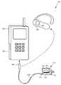
- Smart power management system 100in FIG. 1 , includes power conversion unit (PCU) 110 , electronic devices 120 and 130 , and wired power conduit 116 .
- PCU 110can be configured to connect to a mains alternating current (AC) power line through a standard wall mounted electrical socket, using mains adapter 111 , and to provide power to electronic device 120 or 130 using wired power conduit 116 .
- ACalternating current
- wired power conduit 116can be connected to PCU 110 through connector 117 , which may be a fixed connection or a detachable modular connection, such as through a Universal Serial Bus (USB) interface plug-in connector, for example.
- Wired power conduit 116can connect PCU 110 to electronic device 120 or 130 through modular connector 118 , which may be a mini-USB connector, for example, or any modular connector suitable for providing an interface between wired power conduit 116 and an electronic device or system receiving power.
- Wired power conduit 116can serve as a power transfer connection between PCU 110 and electronic device 120 or 130 and can be used to transfer power to operate either electronic device and/or charge their batteries (e.g., battery 122 of electronic device 120 or battery 132 of electronic device 130 ).
- PCU 110may be configured to provide power to a plurality of various individual electronic devices and/or systems, each having their own specific power requirements, by, for example, including multiple power conduits connecting each device to PCU 110 substantially simultaneously.
- PCU 110may be configured to provide a variable output to any of a plurality of electronic devices, but to do so in combination with a single electronic device or system at a time.
- PCU 110is configured to support a communication channel between itself and the electronic devices or systems to which it is connected.
- PCU 110includes communication module 112 , power management module (PMM) 114 , and pairing module 115 .
- Communication module 112can be configured to send and receive information (e.g., state information, power management parameters and/or pairing information) between PCU 110 and electronic devices 120 and 130 , for example, over communication channels established between PCU 110 and electronic devices 120 and 130 .
- the wired connectionmay also provide a communication channel for transfer of information.
- powermay instead be transferred through a wireless power conduit (not shown in FIG. 1 ) by inductive coupling, or resonant inductive coupling, for example, as known in the art.
- communication module 112can be configured to use a wireless power conduit as a wireless communication channel.
- Communication module 112can also be configured to support separate wireless communication channels to electronic devices 120 and 130 , such as through a Bluetooth, Bluetooth LE, WiFi, Near Field Communication (NFC), or other suitable wireless communication protocol, for example, either in addition or as an alternative to a communication channel formed over a power conduit.
- a Bluetooth, Bluetooth LE, WiFi, Near Field Communication (NFC), or other suitable wireless communication protocolfor example, either in addition or as an alternative to a communication channel formed over a power conduit.
- PMM 114may comprise, for example, a microcontroller having multiple digital and analog input/output ports coupled to communications module 112 and to, for example, a programmable variable power supply, as known in the art. PMM 114 can be configured to use information received from communication module 112 to dynamically modify the output power characteristics (e.g., current and voltage levels) of power delivered to, for example, electronic device 120 or 130 in order to efficiently and accurately power electronic device 120 or 130 or charge respective batteries 122 or 132 . PMM 114 can also be configured to detect a power connection with an electronic device by sensing, for example, a change in output impedance as measured across a power conduit.
- output power characteristicse.g., current and voltage levels
- the combined efforts of communication module 112 and PMM 114can be used to enable PMM 114 to regulate the output power characteristics of power delivered to electronic device 120 according to information (e.g., power management parameters) exchanged between, for example, electronic device 120 and PCU 110 over a communication channel. Consequently, embodiments of the present invention can be used to provide power to many different electronic devices, which can dramatically extend the useful lifetime of PCU 110 while reducing a need for multiple conventional matched power supplies.
- informatione.g., power management parameters
- Pairing module 115may comprise, for example, a microcontroller having multiple digital and analog input/output ports coupled to communications module 112 and to, for example, a data storage device (e.g., a flash memory device, or a bank of static random access memory) as known in the art. Pairing module 115 can be configured to use, for example, pairing information received from communication module 112 to pair electronic devices (e.g., electronic devices 120 and 130 ) when they are placed in communication with PCU 110 . Once paired, electronic devices 120 and 130 can be configured to communicate with each other securely, exclusively, and/or transparently (e.g., without additional help from a user or PCU 110 ) as known in the art, for example.
- a data storage devicee.g., a flash memory device, or a bank of static random access memory
- Such post-pairing configurationsmay be defined by instructions comprising a portion of the pairing information received by pairing module 115 and used to pair electronic devices 120 and 130 .
- Pairing module 115can also be configured to store all such pairing information and/or other transmitted information for subsequent use when, for example, pairing other electronic devices.
- paring module 115may also comprise a physical authentication device, not shown in FIG. 1 , that can be used to enable or disable a pairing function of pairing module 115 .
- a physical authentication devicemay comprise a fingerprint scanner, or an electronic key fob detector for recognizing an electronic key fob exhibiting, for example, a specific electronic signature, as known in the art.
- Pairing module 115can be configured to temporarily enable a pairing function after a successful authentication of pairing module 115 , for example, such as when a scanned fingerprint matches another previously stored in pairing module 115 , or while the presence of a specific electronic key fob is detected by PCU 110 .
- PCU 110may also include various user interaction devices, such as lighted status indicators, or physical switches, for example, that can be coupled with any modules comprising PCU 110 .
- a lighted status indicatormay comprise, for example, a colored light emitting diode (LED) or strip of LEDs configured to indicate a communication link status of communication module 114 , for example, or a failed authentication of pairing module 115 .
- a physical switchmay comprise, for example, a momentary push-button switch that can be configured to communicate, for example, to pairing module 115 that a pairing function must be restarted with new pairing information because an already paired device has been lost or compromised, for example.
- FIG. 2shows a flowchart illustrating a method for pairing an electronic device to another according to an embodiment of the present invention.
- Certain details and featureshave been left out of flowchart 200 that are apparent to a person of ordinary skill in the art.
- a stepmay consist of one or more substeps or may involve specialized equipment or materials, as known in the art.
- Steps 201 through 205 indicated in flowchart 200are sufficient to describe one embodiment of the present invention; however, other embodiments of the invention may make use of steps different from those shown in flowchart 200 .
- step 201 of flowchart 200comprises detecting a power connection between a first electronic device and a PCU.
- the first electronic devicemay be, for example, any electronic device able to communicate with a PCU and pair with other electronic devices, and it may or may not have an internal power storage device, such as a battery.
- the PCUcan comprise a communication module, a PMM and a pairing module, and can be configured to draw power from a mains adapter, such as PCU 110 of FIG. 1 described above.
- a PMM of the PCUmay be configured to sense, for example, a change in output impedance over a power conduit and detect a power connection with the PCU.
- step 202 of flowchart 200comprises establishing a first communication link between the first electronic device and the PCU.
- the first communication linkmay be over a wired or wireless power conduit, a wired or wireless communication channel, or any combination of those, and can be established, for example, by a communication module working in conjunction with a pairing module and/or a PMM.
- step 203 of flowchart 200comprises the PCU receiving pairing information from the first electronic device.
- either the PCU or the electronic devicemay initiate a transfer of pairing information by, for example, transmitting an identity description used to distinguish devices to be paired from other devices, or by requesting a numerical authentication key or other security data.
- An identity descriptionmay comprise an electronic device's serial number, universal product code (UPC), network address, manufacturer, model number, or any other collection of numbers, symbols or text that can distinguish one or more electronic devices from other electronic devices.
- UPCuniversal product code
- Security datamay comprise any data that can distinguish a communication of one or more electronic devices from other communications, for example, or data that can be used to secure communications generally, as known in the art. Pairing information transfer may begin transparently (e.g., without any intervention by a user), for example. Further, any pairing information received by the PCU may be stored within the pairing module of the PCU, as described above.
- step 204 of flowchart 200comprises establishing a second communication link between a second electronic device and the PCU.
- the second communication linkmay be completely independent of the first communication link, and, like the first communication link, may be over a wired or wireless power conduit, a wired or wireless communication channel, or any combination of those.
- the second communication linkcan be established, for example, by a communication module working in conjunction with a pairing module and/or a PMM, and can operate substantially simultaneously with the first communication link.
- step 205 of flowchart 200comprises using the pairing information to pair the second electronic device to the first electronic device. Pairing may happen transparently, and may or may not continue for an extended period of time. For example, if the pairing information transmitted to the PCU by the first electronic device comprises an identity description, as described above, the PCU's pairing module may request an identity description from the second electronic device and compare it to, for example, a stored version of the identity description transmitted by the first electronic device. If the identity descriptions match, then the PCU can pair the devices by, for example, transmitting security data (e.g., an authentication key) generated by the PCU to both devices.
- security datae.g., an authentication key
- the PCUcan be configured to pair the devices if they meet certain predetermined criteria, once again, for example, by transmitting security data, such as an authentication key, generated by the PCU to both devices. After such a transmission, the devices may communicate with each other using security data to negotiate, for example, a secure communication protocol, as known in the art.
- a secure communication protocolcan be used to transmit any information over any communication channel formed between the first and second electronic devices, including those communication channels supporting the previously formed first and second communication links with the PCU.
- the PCUcan be configured, for example, to simply re-transmit the security data to any electronic device it subsequently communicates with, such as the second electronic device, and thereby pair the second device to the first electronic device, as described above.
- security datae.g., an already generated authentication key
- a PCUcan be configured to retain pairing information sent by a first electronic device, for example, only for a limited time or until some event occurs, as a security feature. For instance, a PCU may receive pairing information from a first electronic device comprising security data and an instruction that only the next device connected to the PCU is to be paired. If a third electronic device is connected to the PCU after a second electronic device has been paired, as described above, for example, that third device may be powered by the PCU, but may not be paired with the other electronic devices because the pairing information provided by the first electronic device has not been retained by the PCU. Under other circumstances, pairing information may instead comprise an instruction to pair all devices connected to a PCU at the same time, for example, or all devices connected to a PCU over a period of time.
- a PCUmay be configured instead to un-pair electronic devices in much the same way as it may be used to pair them.
- a first devicemay transmit paring information to a PCU that comprises a pairing group's identity descriptions and an instruction to un-pair all devices in that pairing group. Using that information, a PCU can be configured to un-pair, transparently, any electronic devices in that pair group that are subsequently connected to the PCU.
- a PCUmay comprise a user selectable switch that can be used to restart a pairing function of the PCU. Upon such a switch being selected, a PCU can be configured to un-pair all currently connected electronic devices from their pair group or groups, for example, and re-pair all the devices as a single pair group using a newly generated authentication key, for example.
- a first electronic devicecan be connected to a PCU having existing connections, e.g., wired, wireless, or both wired and wireless, to one or more other electronic devices.
- transfer of pairing information from the first electronic device to the PCUcould be followed by substantially immediate transfer of the pairing information to one or more of the other connected devices, without additional intervening disconnect or connect operations.
- the present inventive conceptsprovide a powering system that can significantly increase the convenience of using those electronic devices. Additionally, by providing a system that can transparently facilitate secure transfer of information between connected electronic devices over, for example, mixed communication channels (i.e., one a wired communication channel formed over a wired power conduit and another formed over a wireless communication channel separate from a power conduit, for example), the present inventive concepts compound the above increase in convenience while retaining important communication security features.
- mixed communication channelsi.e., one a wired communication channel formed over a wired power conduit and another formed over a wireless communication channel separate from a power conduit, for example
Landscapes
- Engineering & Computer Science (AREA)
- Power Engineering (AREA)
- Computer Networks & Wireless Communication (AREA)
- Power Sources (AREA)
- Charge And Discharge Circuits For Batteries Or The Like (AREA)
Abstract
Description
Claims (23)
Priority Applications (9)
| Application Number | Priority Date | Filing Date | Title |
|---|---|---|---|
| US13/004,836US9178363B2 (en) | 2010-01-26 | 2011-01-11 | Smart powering and pairing system and related method |
| EP11009946.2AEP2474880B1 (en) | 2011-01-11 | 2011-12-19 | Smart powering and pairing system and related method |
| EP19169595.6AEP3584675B1 (en) | 2011-01-11 | 2011-12-19 | Smart powering and pairing system and related method |
| CN201210004160.4ACN102593885B (en) | 2011-01-11 | 2012-01-09 | Intelligent power supply and pair system, method and power conversion unit |
| TW101100797ATWI550986B (en) | 2011-01-11 | 2012-01-09 | Smart power supply and pairing system, power conversion unit PCU and power conversion unit PCU applied to smart power supply and pairing system, method for pairing first electronic device and second electronic device |
| KR1020120003493AKR101357838B1 (en) | 2011-01-11 | 2012-01-11 | Smart powering and pairing system and related method |
| HK12108659.1AHK1167933B (en) | 2011-01-11 | 2012-09-05 | Smart powering and pairing system, related method and power converting unit |
| US14/858,109US20160006257A1 (en) | 2010-01-26 | 2015-09-18 | Smart Powering and Pairing System and Related Method |
| US16/278,193US10797489B2 (en) | 2010-01-26 | 2019-02-18 | Smart powering and pairing system and related method |
Applications Claiming Priority (2)
| Application Number | Priority Date | Filing Date | Title |
|---|---|---|---|
| US33684510P | 2010-01-26 | 2010-01-26 | |
| US13/004,836US9178363B2 (en) | 2010-01-26 | 2011-01-11 | Smart powering and pairing system and related method |
Related Child Applications (1)
| Application Number | Title | Priority Date | Filing Date |
|---|---|---|---|
| US14/858,109ContinuationUS20160006257A1 (en) | 2010-01-26 | 2015-09-18 | Smart Powering and Pairing System and Related Method |
Publications (2)
| Publication Number | Publication Date |
|---|---|
| US20110181111A1 US20110181111A1 (en) | 2011-07-28 |
| US9178363B2true US9178363B2 (en) | 2015-11-03 |
Family
ID=44308412
Family Applications (3)
| Application Number | Title | Priority Date | Filing Date |
|---|---|---|---|
| US13/004,836Active2031-05-29US9178363B2 (en) | 2010-01-26 | 2011-01-11 | Smart powering and pairing system and related method |
| US14/858,109AbandonedUS20160006257A1 (en) | 2010-01-26 | 2015-09-18 | Smart Powering and Pairing System and Related Method |
| US16/278,193ActiveUS10797489B2 (en) | 2010-01-26 | 2019-02-18 | Smart powering and pairing system and related method |
Family Applications After (2)
| Application Number | Title | Priority Date | Filing Date |
|---|---|---|---|
| US14/858,109AbandonedUS20160006257A1 (en) | 2010-01-26 | 2015-09-18 | Smart Powering and Pairing System and Related Method |
| US16/278,193ActiveUS10797489B2 (en) | 2010-01-26 | 2019-02-18 | Smart powering and pairing system and related method |
Country Status (1)
| Country | Link |
|---|---|
| US (3) | US9178363B2 (en) |
Cited By (2)
| Publication number | Priority date | Publication date | Assignee | Title |
|---|---|---|---|---|
| USD760702S1 (en)* | 2015-04-24 | 2016-07-05 | Samsung Electronics Co., Ltd. | Remote controller |
| US20170187148A1 (en)* | 2015-12-29 | 2017-06-29 | Robert Andrew Priore | Independently powered usb connector |
Families Citing this family (4)
| Publication number | Priority date | Publication date | Assignee | Title |
|---|---|---|---|---|
| US9654968B2 (en)* | 2012-07-17 | 2017-05-16 | Texas Instruments Incorporated | Certified-based control unit-key fob pairing |
| CN105848086B (en)* | 2015-01-29 | 2019-08-16 | 宏达国际电子股份有限公司 | Internet of things system and control method |
| US11061795B2 (en) | 2016-08-22 | 2021-07-13 | Optimal Plus Ltd. | Methods of smart pairing |
| US11068478B2 (en) | 2017-03-15 | 2021-07-20 | Optimal Plus Ltd. | Augmenting reliability models for manufactured products |
Citations (19)
| Publication number | Priority date | Publication date | Assignee | Title |
|---|---|---|---|---|
| US6255800B1 (en) | 2000-01-03 | 2001-07-03 | Texas Instruments Incorporated | Bluetooth enabled mobile device charging cradle and system |
| US6754092B2 (en)* | 2002-06-27 | 2004-06-22 | International Business Machines Corporation | Method and apparatus for reducing power consumption for power supplied by a voltage adapter |
| EP1635508A1 (en) | 2004-09-08 | 2006-03-15 | Koninklijke Philips Electronics N.V. | Secure pairing for wireless communications devices |
| US20060271800A1 (en)* | 2005-05-28 | 2006-11-30 | Jun Li | Power saving apparatus and method |
| US20080008359A1 (en)* | 2001-07-10 | 2008-01-10 | American Express Travel Related Services Company, Inc. | System for biometric security using a fob |
| US20080081676A1 (en) | 2006-09-29 | 2008-04-03 | Rosemount, Inc. | Power management system for a field device on a wireless network |
| US20080106148A1 (en) | 2004-05-19 | 2008-05-08 | Electronic Data Control Pty. Ltd. | Power Saver Controller |
| US7573159B1 (en) | 2001-10-22 | 2009-08-11 | Apple Inc. | Power adapters for powering and/or charging peripheral devices |
| US20090235107A1 (en)* | 2004-05-19 | 2009-09-17 | Ember Technologies Pty Ltd | Power supply control device |
| US20090271047A1 (en)* | 2008-04-28 | 2009-10-29 | Masataka Wakamatsu | Power transmitting apparatus, power receiving apparatus, power transmission method, program, and power transmission system |
| US20090284245A1 (en)* | 2008-05-13 | 2009-11-19 | Qualcomm Incorporated | Wireless power transfer for appliances and equipments |
| US20100019583A1 (en)* | 2008-07-25 | 2010-01-28 | Igo, Inc. | Load condition controlled power module |
| WO2010057224A1 (en) | 2008-11-13 | 2010-05-20 | Qualcomm Incorporated | Wireless power and data transfer for electronic devices |
| US20100145542A1 (en)* | 2007-03-14 | 2010-06-10 | Zonit Structured Solutions, Llc | Smart electrical outlets and associated networks |
| US20100146308A1 (en)* | 2008-09-26 | 2010-06-10 | Richard Gioscia | Portable power supply device for mobile computing devices |
| US20100244576A1 (en)* | 2009-03-25 | 2010-09-30 | Qualcomm Incorporated | Optimization of wireless power devices |
| US20100279606A1 (en)* | 2009-02-13 | 2010-11-04 | Qualcomm Incorporated | Wireless power and wireless communication for electronic devices |
| US20110159813A1 (en)* | 2009-12-24 | 2011-06-30 | Sony Computer Entertainment Inc. | Wireless Device Pairing and Grouping Methods |
| US20110260556A1 (en)* | 2008-09-30 | 2011-10-27 | Tectonica Australia Pty Ltd. | Personal portable power distribution apparatus |
Family Cites Families (1)
| Publication number | Priority date | Publication date | Assignee | Title |
|---|---|---|---|---|
| US8401473B2 (en) | 2007-01-06 | 2013-03-19 | Apple Inc. | Apparatuses and methods that facilitate the transfer of power and information among electrical devices |
- 2011
- 2011-01-11USUS13/004,836patent/US9178363B2/enactiveActive
- 2015
- 2015-09-18USUS14/858,109patent/US20160006257A1/ennot_activeAbandoned
- 2019
- 2019-02-18USUS16/278,193patent/US10797489B2/enactiveActive
Patent Citations (20)
| Publication number | Priority date | Publication date | Assignee | Title |
|---|---|---|---|---|
| US6255800B1 (en) | 2000-01-03 | 2001-07-03 | Texas Instruments Incorporated | Bluetooth enabled mobile device charging cradle and system |
| US20080008359A1 (en)* | 2001-07-10 | 2008-01-10 | American Express Travel Related Services Company, Inc. | System for biometric security using a fob |
| US7766698B1 (en)* | 2001-10-22 | 2010-08-03 | Apple Inc. | Power adapters for powering and/or charging peripheral devices |
| US7573159B1 (en) | 2001-10-22 | 2009-08-11 | Apple Inc. | Power adapters for powering and/or charging peripheral devices |
| US6754092B2 (en)* | 2002-06-27 | 2004-06-22 | International Business Machines Corporation | Method and apparatus for reducing power consumption for power supplied by a voltage adapter |
| US20080106148A1 (en) | 2004-05-19 | 2008-05-08 | Electronic Data Control Pty. Ltd. | Power Saver Controller |
| US20090235107A1 (en)* | 2004-05-19 | 2009-09-17 | Ember Technologies Pty Ltd | Power supply control device |
| EP1635508A1 (en) | 2004-09-08 | 2006-03-15 | Koninklijke Philips Electronics N.V. | Secure pairing for wireless communications devices |
| US20060271800A1 (en)* | 2005-05-28 | 2006-11-30 | Jun Li | Power saving apparatus and method |
| US20080081676A1 (en) | 2006-09-29 | 2008-04-03 | Rosemount, Inc. | Power management system for a field device on a wireless network |
| US20100145542A1 (en)* | 2007-03-14 | 2010-06-10 | Zonit Structured Solutions, Llc | Smart electrical outlets and associated networks |
| US20090271047A1 (en)* | 2008-04-28 | 2009-10-29 | Masataka Wakamatsu | Power transmitting apparatus, power receiving apparatus, power transmission method, program, and power transmission system |
| US20090284245A1 (en)* | 2008-05-13 | 2009-11-19 | Qualcomm Incorporated | Wireless power transfer for appliances and equipments |
| US20100019583A1 (en)* | 2008-07-25 | 2010-01-28 | Igo, Inc. | Load condition controlled power module |
| US20100146308A1 (en)* | 2008-09-26 | 2010-06-10 | Richard Gioscia | Portable power supply device for mobile computing devices |
| US20110260556A1 (en)* | 2008-09-30 | 2011-10-27 | Tectonica Australia Pty Ltd. | Personal portable power distribution apparatus |
| WO2010057224A1 (en) | 2008-11-13 | 2010-05-20 | Qualcomm Incorporated | Wireless power and data transfer for electronic devices |
| US20100279606A1 (en)* | 2009-02-13 | 2010-11-04 | Qualcomm Incorporated | Wireless power and wireless communication for electronic devices |
| US20100244576A1 (en)* | 2009-03-25 | 2010-09-30 | Qualcomm Incorporated | Optimization of wireless power devices |
| US20110159813A1 (en)* | 2009-12-24 | 2011-06-30 | Sony Computer Entertainment Inc. | Wireless Device Pairing and Grouping Methods |
Non-Patent Citations (4)
| Title |
|---|
| "Combined Antenna and Inductive Power Receiver" Ben-Shalom, et al. Apr. 1, 2010 . |
| "Combined Antenna and Inductive Power Receiver" Ben-Shalom, et al. Apr. 1, 2010 <http://www.sumobrain.com/patents/wipo/Combined-antenna-inductive-power-receiver/WO2010035256.html>. |
| "Verizon LG Decoy Cell Phone Integrated Bluetooth Headset Now Available" Andrew Tingle Jun. 17, 2008 <http://nexus404.com/Blog/2008/06/17/verizon-lg-decoy-cell-phone-integrated-bluetooth-headset-now-available-lg-vx8610-multimedia-handset-hits-verizon/>. |
| Chinese Office Action dated Nov. 22, 2013, in corresponding application 201210004160.4. |
Cited By (2)
| Publication number | Priority date | Publication date | Assignee | Title |
|---|---|---|---|---|
| USD760702S1 (en)* | 2015-04-24 | 2016-07-05 | Samsung Electronics Co., Ltd. | Remote controller |
| US20170187148A1 (en)* | 2015-12-29 | 2017-06-29 | Robert Andrew Priore | Independently powered usb connector |
Also Published As
| Publication number | Publication date |
|---|---|
| US20160006257A1 (en) | 2016-01-07 |
| US20190181649A1 (en) | 2019-06-13 |
| US10797489B2 (en) | 2020-10-06 |
| US20110181111A1 (en) | 2011-07-28 |
Similar Documents
| Publication | Publication Date | Title |
|---|---|---|
| US10797489B2 (en) | Smart powering and pairing system and related method | |
| US9153993B2 (en) | Smart charging system and related method | |
| CN208421800U (en) | Wireless screen transmission device | |
| US8238823B2 (en) | Method for ensuring a secure NFC functionality of a wireless mobile communication device and wireless mobile communication device having a secure NFC functionality | |
| EP2203966B1 (en) | Method of controlling a power transfer system and power transfer system | |
| US8024012B2 (en) | Intelligent wireless power charging system | |
| CN104836270B (en) | Connector converter and vehicle charging system and method of use | |
| US7375493B2 (en) | Inductive battery charger | |
| EP2474880B1 (en) | Smart powering and pairing system and related method | |
| US10483866B2 (en) | Smart power delivery system and related method | |
| US20090111501A1 (en) | Wireless communication system and its device | |
| US9780600B2 (en) | Method and apparatus for wirelessly recharging batteries | |
| JP2022502183A (en) | Power-adaptive, human cavity scanning device | |
| WO2006123200A2 (en) | Multiple source/multiple device connector | |
| US9350170B2 (en) | Smart power management system and related method | |
| CN208797289U (en) | A kind of visible light communication insert row and socket | |
| HK1167933B (en) | Smart powering and pairing system, related method and power converting unit | |
| CN110445239A (en) | Terminal charging method and terminal charging system | |
| CN205228575U (en) | Liquid level detection system | |
| CN119516753A (en) | Wireless communicators, work systems and tool systems | |
| CN107070877B (en) | Universal power adapter protocol (UPP) | |
| JP6851010B2 (en) | Charging device, communication system |
Legal Events
| Date | Code | Title | Description |
|---|---|---|---|
| AS | Assignment | Owner name:BROADCOM CORPORATION, CALIFORNIA Free format text:ASSIGNMENT OF ASSIGNORS INTEREST;ASSIGNORS:WALLEY, JOHN;HULVEY, ROBERT;SIGNING DATES FROM 20110110 TO 20110111;REEL/FRAME:025668/0369 | |
| STCF | Information on status: patent grant | Free format text:PATENTED CASE | |
| AS | Assignment | Owner name:BANK OF AMERICA, N.A., AS COLLATERAL AGENT, NORTH CAROLINA Free format text:PATENT SECURITY AGREEMENT;ASSIGNOR:BROADCOM CORPORATION;REEL/FRAME:037806/0001 Effective date:20160201 Owner name:BANK OF AMERICA, N.A., AS COLLATERAL AGENT, NORTH Free format text:PATENT SECURITY AGREEMENT;ASSIGNOR:BROADCOM CORPORATION;REEL/FRAME:037806/0001 Effective date:20160201 | |
| AS | Assignment | Owner name:AVAGO TECHNOLOGIES GENERAL IP (SINGAPORE) PTE. LTD., SINGAPORE Free format text:ASSIGNMENT OF ASSIGNORS INTEREST;ASSIGNOR:BROADCOM CORPORATION;REEL/FRAME:041706/0001 Effective date:20170120 Owner name:AVAGO TECHNOLOGIES GENERAL IP (SINGAPORE) PTE. LTD Free format text:ASSIGNMENT OF ASSIGNORS INTEREST;ASSIGNOR:BROADCOM CORPORATION;REEL/FRAME:041706/0001 Effective date:20170120 | |
| AS | Assignment | Owner name:BROADCOM CORPORATION, CALIFORNIA Free format text:TERMINATION AND RELEASE OF SECURITY INTEREST IN PATENTS;ASSIGNOR:BANK OF AMERICA, N.A., AS COLLATERAL AGENT;REEL/FRAME:041712/0001 Effective date:20170119 | |
| AS | Assignment | Owner name:AVAGO TECHNOLOGIES INTERNATIONAL SALES PTE. LIMITE Free format text:MERGER;ASSIGNOR:AVAGO TECHNOLOGIES GENERAL IP (SINGAPORE) PTE. LTD.;REEL/FRAME:047229/0408 Effective date:20180509 | |
| AS | Assignment | Owner name:AVAGO TECHNOLOGIES INTERNATIONAL SALES PTE. LIMITE Free format text:CORRECTIVE ASSIGNMENT TO CORRECT THE EFFECTIVE DATE PREVIOUSLY RECORDED ON REEL 047229 FRAME 0408. ASSIGNOR(S) HEREBY CONFIRMS THE THE EFFECTIVE DATE IS 09/05/2018;ASSIGNOR:AVAGO TECHNOLOGIES GENERAL IP (SINGAPORE) PTE. LTD.;REEL/FRAME:047349/0001 Effective date:20180905 | |
| AS | Assignment | Owner name:AVAGO TECHNOLOGIES INTERNATIONAL SALES PTE. LIMITE Free format text:CORRECTIVE ASSIGNMENT TO CORRECT THE PATENT NUMBER 9,385,856 TO 9,385,756 PREVIOUSLY RECORDED AT REEL: 47349 FRAME: 001. ASSIGNOR(S) HEREBY CONFIRMS THE MERGER;ASSIGNOR:AVAGO TECHNOLOGIES GENERAL IP (SINGAPORE) PTE. LTD.;REEL/FRAME:051144/0648 Effective date:20180905 | |
| MAFP | Maintenance fee payment | Free format text:PAYMENT OF MAINTENANCE FEE, 4TH YEAR, LARGE ENTITY (ORIGINAL EVENT CODE: M1551); ENTITY STATUS OF PATENT OWNER: LARGE ENTITY Year of fee payment:4 | |
| MAFP | Maintenance fee payment | Free format text:PAYMENT OF MAINTENANCE FEE, 8TH YEAR, LARGE ENTITY (ORIGINAL EVENT CODE: M1552); ENTITY STATUS OF PATENT OWNER: LARGE ENTITY Year of fee payment:8 |