US9178319B2 - Electrical connector with shieldingthereof - Google Patents
Electrical connector with shieldingthereofDownload PDFInfo
- Publication number
- US9178319B2 US9178319B2US14/149,788US201414149788AUS9178319B2US 9178319 B2US9178319 B2US 9178319B2US 201414149788 AUS201414149788 AUS 201414149788AUS 9178319 B2US9178319 B2US 9178319B2
- Authority
- US
- United States
- Prior art keywords
- contacts
- insulator
- terminal module
- electrical connector
- lower terminal
- Prior art date
- Legal status (The legal status is an assumption and is not a legal conclusion. Google has not performed a legal analysis and makes no representation as to the accuracy of the status listed.)
- Active, expires
Links
- 239000012212insulatorSubstances0.000claimsabstractdescription42
- 230000013011matingEffects0.000claimsabstractdescription39
- 230000002787reinforcementEffects0.000claimsabstractdescription16
- 230000000717retained effectEffects0.000claimsabstractdescription8
- 230000014759maintenance of locationEffects0.000claimsabstractdescription7
- 238000007493shaping processMethods0.000claimsdescription6
- 230000008878couplingEffects0.000claims2
- 238000010168coupling processMethods0.000claims2
- 238000005859coupling reactionMethods0.000claims2
- 238000005452bendingMethods0.000claims1
- 230000000295complement effectEffects0.000claims1
- 230000008901benefitEffects0.000description2
- 230000005540biological transmissionEffects0.000description2
- 238000010586diagramMethods0.000description2
- 230000003014reinforcing effectEffects0.000description2
- 238000000034methodMethods0.000description1
Images


Classifications
- H—ELECTRICITY
- H01—ELECTRIC ELEMENTS
- H01R—ELECTRICALLY-CONDUCTIVE CONNECTIONS; STRUCTURAL ASSOCIATIONS OF A PLURALITY OF MUTUALLY-INSULATED ELECTRICAL CONNECTING ELEMENTS; COUPLING DEVICES; CURRENT COLLECTORS
- H01R13/00—Details of coupling devices of the kinds covered by groups H01R12/70 or H01R24/00 - H01R33/00
- H01R13/648—Protective earth or shield arrangements on coupling devices, e.g. anti-static shielding
- H01R13/658—High frequency shielding arrangements, e.g. against EMI [Electro-Magnetic Interference] or EMP [Electro-Magnetic Pulse]
- H01R13/6581—Shield structure
- H01R13/6585—Shielding material individually surrounding or interposed between mutually spaced contacts
- H—ELECTRICITY
- H01—ELECTRIC ELEMENTS
- H01R—ELECTRICALLY-CONDUCTIVE CONNECTIONS; STRUCTURAL ASSOCIATIONS OF A PLURALITY OF MUTUALLY-INSULATED ELECTRICAL CONNECTING ELEMENTS; COUPLING DEVICES; CURRENT COLLECTORS
- H01R24/00—Two-part coupling devices, or either of their cooperating parts, characterised by their overall structure
- H01R24/60—Contacts spaced along planar side wall transverse to longitudinal axis of engagement
Definitions
- the present inventionrelates to an electrical receptacle connector, and more particularly to an I/O receptacle connector having a mating tongue with contacting sections of the corresponding contacts on two opposite surfaces thereon wherein a shielding/reinforcement plate between the two opposite surface under condition that the shielding/reinforcement plate are mechanically and electrically connected to some of the grounding contacts.
- the inventionis related to the copending application Ser. No. 13/479,289 filed May 24, 2012.
- a connector capable of transmitting high-speed differential signalsis used as an interface connector or an internal connector of a digital appliance or a PC.
- Such connectorincludes a plurality of signal contacts and a plurality of ground contacts.
- the signal contactsare paired in order to transmit differential signals in the manner known in the art.
- the terminal portion side of the contacts to be connected to a boardthe terminal portions are arranged in a plurality of rows because the terminal portions are inserted into a plurality of through holes, respectively.
- an object of the present inventionis to provide An electrical connector for mating with a plug and mounting to a printed circuit board, includes an insulative housing with a forwardly extending mating tongue thereof.
- a terminal moduleincludes an insulator associated with a plurality of contacts commonly assembled into the housing. Those contacts are categorized with the differential pairs, the grounding contacts and the power contacts while each of the contacts includes a front contacting section exposed upon the mating tongue, a middle retention section retained to the insulator, and a rear tail section extending out of the housing.
- a metallic shielding/reinforcement plate associated with the terminal moduleis assembled into the housing, and includes a front region inserted into the mating tongue, a middle region with a spring tang to mechanically and electrically connected to the selected grounding contact, and a rear tail section extending out of the housing.
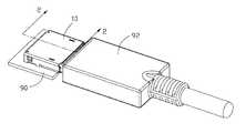
- FIG. 1is a perspective view showing the mated receptacle connector and plug connector in accordance with a first embodiment of the present invention
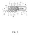
- FIG. 2is a side cross-sectional view of the receptacle connector of FIG. 1 ;
- FIG. 3is a front cross-sectional view of the receptacle connector of FIG. 1 ;
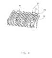
- FIG. 4is a perspective view of the contacts of the receptacle connector of FIG. 1 ;
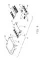
- FIG. 5is an exploded perspective view of the receptacle connector of FIG. 1 ;
- FIG. 6is a partially exploded perspective view of the receptacle connector of FIG. 1 ;
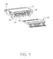
- FIG. 7is another partially exploded perspective view of the receptacle connector of FIG. 1 ;
- FIG. 8is a perspective view of the receptacle connector in accordance with another embodiment of the present invention.
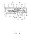
- FIG. 9is a cross-sectional view of the receptacle connector of FIG. 8 ;
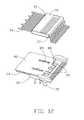
- FIG. 10is an exploded downward perspective view of the receptacle connector of FIG. 8 ;
- FIG. 11is an exploded upward perspective view of the receptacle connector of FIG. 8 .
- FIG. 12is a partially assembled downward perspective view of the terminal modules of receptacle connector
- FIG. 13is a partially assembled upward perspective view of the terminal modules of receptacle connector
- FIG. 14is a exploded perspective view of the receptacle connector with the terminal modules are preassembled together;
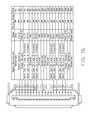
- FIG. 15is a diagram to show the positions of the different categorized contacts of a receive side.
- FIG. 16is a diagram to show the positions of the different categorized contacts of a transmit side.
- an electrical connector assembly of a first embodimentincluding a receptacle connector 10 mounted upon a printed circuit board 90 and a plug cable connector 92 mated with each other.
- the receptacle connector 10includes an insulative housing 12 defining a rear base 14 with a receiving cavity 16 therein and a front mating tongue 18 extending forwardly from the base 14 .
- the receiving cavity 16opens rearwards.
- An upper/first terminal module 20 and a lower/second terminal module 22are located behind the mating tongue 18 .
- Each of the upper and lower terminal modules 20 , 22includes an insulator 24 , 26 commonly located in the receiving cavity 16 , and a plurality of upper and lower contacts 28 , 30 associatively insert-molded within the corresponding insulator 24 , 26 with contacting sections 32 , 34 extending from font ends of the insulator 24 , 26 and as shown in FIG. 2 , exposed upon opposite upper and lower surfaces 17 , 19 of the mating tongue 18 and tail sections 36 , 40 exposed out of a rear side of the housing 12 for mounting to the printed circuit board 90 .
- the contacts 28 , 30as best shown in FIG. 3 , are categorized with differential pairs 95 , the grounding contacts 97 and the power contacts 99 mixed up with one another as shown in FIG. 15 .
- a metallic shielding/reinforcement plate 42is located between the upper and lower terminal modules 20 , 22 and defines a pair of spring tangs 44 extending upwardly to mechanically and electrically contact the corresponding grounding contacts 82 .
- the shielding/reinforcement plate 42includes a front region 46 extending into the mating tongue 18 for reinforcing the mating tongue 18 , and a pair of rear tail sections 48 extending through the lower insulator 26 for mounting to the printed circuit board 90 , and the mounting tabs 50 fastened to the lower insulator 26 for fastening the shielding/reinforcement plate 42 to the lower insulator 26 .
- the mounting tabs 50 and the tail sections 48are lined and alternated with each other.
- the shielding/reinforcement plate 42is first assembled to the lower insulator 26 and commonly forwardly inserted into the housing 12 from a rear side of the housing 12 wherein the contacting sections 34 of the lower contacts 30 are exposed upon the lower surface 19 of the mating tongue 18 and the lower insulator 26 is received in a lower portion of the receiving cavity 16 .
- the upper terminal module 20is successively forwardly inserted into an upper portion of the receiving cavity 16 with the contacting section 32 exposed upon the upper surface 17 of the mating tongue 18 .
- the lower terminal module 22has no projection portion higher than the spring tangs 44 so that the upper terminal module 22 is inserted into the receiving cavity 16 after the lower terminal module 22 is retained in the receiving cavity.
- a metallic shell 52encloses the housing 12 and a rear wall 54 of the shell 52 is bent downwardly to shield the housing 12 .
- a receptacle connector 60 of another embodiment of the present inventionincludes an insulative housing 62 defining a rear base 64 and a front mating tongue 66 extending forwardly from the base portion 64 and defining opposite upper and lower surfaces thereon.
- a plurality of contact receiving passageways 68are formed in the corresponding upper and lower surfaces.
- Upper and lower terminal modules 70are stacked with each other in a vertical direction.
- Each of the upper and lower terminal modules 70includes an insulator 72 received in the base 64 , and a plurality of contacts 74 are integrally insert-molded in the insulator 72 . Similar to those in the first embodiment, those contacts 74 are categorized with the differential pairs, the grounding contacts and the power contacts mixed up with one another.
- Each of the contacts 74includes a front contacting section 76 extending from a front end of the insulator 72 and received in the corresponding passageway 68 , a middle retention section 78 as best shown in FIG. 9 embedded within the insulator 72 and a rear tail section 80 extending out of the insulator 72 and the housing 62 for mounting to a printed circuit board.
- a metallic shielding/reinforcement plate 82is sandwiched between the upper and lower terminal modules 70 and includes a front region 84 inserted into a slit of the mating tongue 66 for reinforcing the mating tongue 66 , a middle region 86 sandwiched between the insulators 72 of the upper and lower modules 70 , and a rear region 88 extending downwardly through the corresponding through holes 79 of the insulator 72 of the lower terminal module 70 for mounting to the printed circuit board.
- a pair of spring tangs 89unitarily extend from the middle region 86 toward to selectively contact the corresponding grounding contacts 74 of the upper terminal module 70 .
- the insulator 72 of the upper terminal module 70defines in an underside two apertures 73 corresponding to the selected grounding contacts 74 for allowing such spring tangs 89 to extend therethrough for contacting such selected grounding contacts 74 .
- a metallic shell 96is assembled to and encloses the housing 62 to cooperate with the mating tongue 66 to define a mating port for receiving a plug.
- the upper and lower terminal modules 70are first assembled to each other before commonly assembled into the housing 62 .
- the insulator 72 of the lower terminal module 70include a pair of mounting holes 75 and an insulator 72 of the upper terminal module 70 includes a pair of mounting posts 77 received in the corresponding mounting holes 75 respectively.
- the shielding/reinforcement plate 82is structured not to hinder engagement between the mounting posts 77 and the mounting holes 75 .
- at least a portion of the mating tongue 66may be provided by at least one of the upper and lower terminal modules 70 for consideration of manufacturability.
- the lower terminal module 70further defines shaping convexes 722 corresponding to the tail sections 80 of the contacts 74 .
- the shaping convexes 722are integrated with a bottom face of the insulator 72 and projecting downwards from the bottom face, which are formed during automotive forming process of the lower terminal module 72 .
- Each tail section 80is fitly surrounded with one shaping convex 722 and pierce through an apex of the shaping convex 722 .
- the contacts 28 , 30defines four channels each including two differential pairs respectively for transmission and reception, and two enlarged power contacts 99 , and three pairs of grounding contacts 97 each sandwiching a corresponding differential pair therebetween while sharing a same mounting tail with each other. Therefore, the differential pair 95 , which is sandwiched by a pair of grounding contacts 97 sharing the same mounting tail, defines the corresponding mounting tails arranged in one row while the shared mounting tails of those three pairs of grounding contacts 97 are located in another row behind.
Landscapes
- Details Of Connecting Devices For Male And Female Coupling (AREA)
- Connector Housings Or Holding Contact Members (AREA)
Abstract
Description
Claims (20)
Priority Applications (2)
| Application Number | Priority Date | Filing Date | Title |
|---|---|---|---|
| US14/149,788US9178319B2 (en) | 2013-01-08 | 2014-01-07 | Electrical connector with shieldingthereof |
| US14/198,582US9252542B2 (en) | 2012-05-24 | 2014-03-05 | Electrical connector with shielding plate thereof |
Applications Claiming Priority (2)
| Application Number | Priority Date | Filing Date | Title |
|---|---|---|---|
| US201361750312P | 2013-01-08 | 2013-01-08 | |
| US14/149,788US9178319B2 (en) | 2013-01-08 | 2014-01-07 | Electrical connector with shieldingthereof |
Related Child Applications (1)
| Application Number | Title | Priority Date | Filing Date |
|---|---|---|---|
| US13/479,289Continuation-In-PartUS8684769B2 (en) | 2012-05-24 | 2012-05-24 | Electrical connector having terminal portions in specific arrangement and a grounding plate for excellent high-frequency characteristics |
Publications (2)
| Publication Number | Publication Date |
|---|---|
| US20140194005A1 US20140194005A1 (en) | 2014-07-10 |
| US9178319B2true US9178319B2 (en) | 2015-11-03 |
Family
ID=51061283
Family Applications (1)
| Application Number | Title | Priority Date | Filing Date |
|---|---|---|---|
| US14/149,788Active2034-01-11US9178319B2 (en) | 2012-05-24 | 2014-01-07 | Electrical connector with shieldingthereof |
Country Status (3)
| Country | Link |
|---|---|
| US (1) | US9178319B2 (en) |
| CN (1) | CN104009338B (en) |
| TW (1) | TWI593199B (en) |
Cited By (38)
| Publication number | Priority date | Publication date | Assignee | Title |
|---|---|---|---|---|
| US20140004744A1 (en)* | 2012-06-29 | 2014-01-02 | Hsiu-Yuan Hsu | Electrical connector with two grounding bars |
| US20150222059A1 (en)* | 2013-07-19 | 2015-08-06 | Foxconn Interconnect Technology Limited | Flippable electrical connector |
| US20150244111A1 (en)* | 2014-02-21 | 2015-08-27 | Lotes Co., Ltd | Electrical connector and electrical connector assembly |
| US20150270646A1 (en)* | 2014-03-24 | 2015-09-24 | Advanced-Connectek Inc. | Electrical connector assembly |
| US20150311645A1 (en)* | 2014-04-28 | 2015-10-29 | Speed Tech Corp. | Universal serial bus connector |
| US20150340791A1 (en)* | 2014-05-22 | 2015-11-26 | Advanced-Connectek Inc. | Electrical receptacle connector and electrical plug connector |
| US20150349447A1 (en)* | 2014-05-30 | 2015-12-03 | Speed Tech Corp. | Contact strip structure |
| US20160043511A1 (en)* | 2014-08-11 | 2016-02-11 | Foxconn Interconnect Technology Limited | Electrical connector and method of making the same |
| US20160087368A1 (en)* | 2014-09-23 | 2016-03-24 | Hubbell Incorporated | Tamper resistant receptacle |
| US20160104976A1 (en)* | 2014-05-21 | 2016-04-14 | Foxconn Interconnect Technology Limited | Electrical connector with improved tongue |
| US20160141797A1 (en)* | 2014-11-14 | 2016-05-19 | Foxconn Interconnect Technology Limited | Cable connector assembly having improved metal shell |
| US20160141792A1 (en)* | 2014-11-14 | 2016-05-19 | Foxconn Interconnect Technology Limited | Waterproof electrical connector |
| US20160141804A1 (en)* | 2014-11-19 | 2016-05-19 | Advanced-Connectek Inc. | Electrical plug connector |
| US20160197443A1 (en)* | 2015-01-06 | 2016-07-07 | Molex, Llc | Electrical connector |
| US20160285191A1 (en)* | 2014-08-08 | 2016-09-29 | Smk Corporation | Electrical conductor |
| US20160294121A1 (en)* | 2015-04-02 | 2016-10-06 | Genesis Technology Usa, Inc. | Three Dimensional Lead-Frames For Reduced Crosstalk |
| US9525241B1 (en)* | 2015-12-28 | 2016-12-20 | Cheng Uei Precision Industry Co., Ltd. | Electrical connector |
| US20170033507A1 (en)* | 2015-07-31 | 2017-02-02 | Advanced-Connectek Inc. | Electrical receptacle connector |
| US20170040750A1 (en)* | 2013-07-19 | 2017-02-09 | Foxconn Interconnect Technology Limted | Flippable electrical connector |
| US20170040747A1 (en)* | 2015-08-07 | 2017-02-09 | Smk Corporation | Electric connector |
| US20170264054A1 (en)* | 2015-02-11 | 2017-09-14 | Foxconn Interconnect Technology Limited | Receptacle connector having improved shielding plate |
| US20170310501A1 (en)* | 2016-04-22 | 2017-10-26 | Foxconn Interconnect Technology Limited | Electrical connector having metallic bracket accommodating pre-assembled metallic plate and upper and lower terminal modules |
| US20170324175A1 (en)* | 2014-07-15 | 2017-11-09 | Lotes Co., Ltd | Method for molding electrical connector |
| US9853387B2 (en)* | 2014-01-22 | 2017-12-26 | Foxconn Interconnect Technology Lmited | Electrical connector having insulative members and method of making the same |
| US9881650B1 (en)* | 2016-12-26 | 2018-01-30 | Western Digital Technologies, Inc. | Connector mitigating crosstalk for high speed communication |
| US20180076581A1 (en)* | 2016-09-14 | 2018-03-15 | Advanced-Connectek Inc. | Electrical receptacle connector |
| US10008811B2 (en)* | 2014-05-30 | 2018-06-26 | Molex, Llc | Electrical connector |
| US10211563B2 (en)* | 2017-05-19 | 2019-02-19 | Foxconn Interconnect Technology Limited | Electrical connector having conductive contacts not being corroded |
| US20190058292A1 (en)* | 2017-08-18 | 2019-02-21 | Foxconn Interconnect Technology Limited | Electrical connector with stacked shielding plates sandwiched between two opposite contact modules |
| US10297943B2 (en)* | 2017-05-05 | 2019-05-21 | Advanced Connectek Inc. | Electrical receptacle connector with plurality of insulating portions structurally separated from each other |
| US10367313B2 (en) | 2017-02-15 | 2019-07-30 | Foxconn Interconnect Technology Limited | Electrical connector having a middle metal plate with two pairs of fingers contacting an upper and lower ground contacts |
| US10411414B2 (en)* | 2017-08-18 | 2019-09-10 | Foxconn Interconnect Technology Limited | Electrical connector with stacked shielding plates sandwiched between two opposite contact modules |
| US10476195B2 (en)* | 2017-03-08 | 2019-11-12 | Advanced Connectek Inc. | Electrical receptacle connector |
| US10998654B2 (en)* | 2017-07-07 | 2021-05-04 | Autonetworks Technologies, Ltd. | Board connector and connection structure for circuit board and board connector |
| US11271354B2 (en) | 2018-03-02 | 2022-03-08 | Hirose Electric Co., Ltd. | Electric connector manufacturing method and electric connector |
| US20220247107A1 (en)* | 2021-02-02 | 2022-08-04 | Foxconn (Kunshan) Computer Connector Co., Ltd. | Card edge connector with improved arrangement of soldering portions of terminals thereof |
| US20220416476A1 (en)* | 2021-06-25 | 2022-12-29 | Chant Sincere Co., Ltd. | Electrical connector |
| NL2031018A (en)* | 2021-12-23 | 2023-06-29 | Zaslavskis Olegs | A connector plug and a connector socket |
Families Citing this family (38)
| Publication number | Priority date | Publication date | Assignee | Title |
|---|---|---|---|---|
| JP4976568B1 (en)* | 2011-04-18 | 2012-07-18 | 日本航空電子工業株式会社 | connector |
| US10826255B2 (en)* | 2013-07-19 | 2020-11-03 | Foxconn Interconnect Technology Limited | Flippable electrical connector |
| US9640885B2 (en) | 2013-11-17 | 2017-05-02 | Apple Inc. | Connector receptacle having a tongue |
| WO2015073974A2 (en) | 2013-11-17 | 2015-05-21 | Apple Inc. | Connector receptacle having a shield |
| CN105765797B (en) | 2013-11-27 | 2019-07-05 | 安费诺富加宜(亚洲)私人有限公司 | Electric connector |
| US9450339B2 (en) | 2014-01-12 | 2016-09-20 | Apple Inc. | Ground contacts for reduced-length connector inserts |
| US9276340B2 (en) | 2014-05-26 | 2016-03-01 | Apple Inc. | Interposers for connecting receptacle tongues to printed circuit boards |
| US9490581B2 (en) | 2014-05-26 | 2016-11-08 | Apple Inc. | Connector insert assembly |
| US9356370B2 (en) | 2014-05-26 | 2016-05-31 | Apple Inc. | Interposer for connecting a receptacle tongue to a printed circuit board |
| US10418763B2 (en) | 2014-05-26 | 2019-09-17 | Apple Inc. | Connector insert assembly |
| US9515439B2 (en) | 2014-05-26 | 2016-12-06 | Apple Inc. | Connector insert assembly |
| TWI573335B (en) | 2014-08-13 | 2017-03-01 | 鴻騰精密科技股份有限公司 | Electrical connector and method of making the same |
| TWI578633B (en) | 2014-08-22 | 2017-04-11 | 鴻騰精密科技股份有限公司 | Electrical connector and method of making the same |
| CN105449465B (en)* | 2014-08-22 | 2018-09-14 | 昆山全方位电子科技有限公司 | 3.1 socket connector of high speed USB equipped with location hole |
| CN105470735B (en)* | 2014-08-28 | 2019-05-17 | 富士康(昆山)电脑接插件有限公司 | Electric connector and its manufacturing method |
| CN105390853A (en)* | 2014-09-03 | 2016-03-09 | 凡甲电子(苏州)有限公司 | Electric connector |
| CN204243365U (en) | 2014-10-27 | 2015-04-01 | 富士康(昆山)电脑接插件有限公司 | electrical connector |
| CN104466511B (en)* | 2014-11-07 | 2016-08-24 | 深圳市正耀科技有限公司 | A kind of connector plug and manufacture assemble method thereof |
| TWI569538B (en)* | 2014-11-21 | 2017-02-01 | 連展科技股份有限公司 | Receptacle electrical connector |
| CN104682137A (en)* | 2015-03-09 | 2015-06-03 | 连展科技(深圳)有限公司 | Electric plug connector |
| CN104795698B (en)* | 2015-05-05 | 2018-03-20 | 昆山嘉华精密工业有限公司 | Electric connector and its manufacture method |
| CN204966770U (en)* | 2015-07-25 | 2016-01-13 | 富士康(昆山)电脑接插件有限公司 | Electric connector |
| CN105048148B (en)* | 2015-08-06 | 2024-08-02 | 连展科技(深圳)有限公司 | Socket electric connector |
| CN105140687B (en)* | 2015-09-17 | 2024-09-27 | 连展科技(深圳)有限公司 | Socket electric connector |
| CN105261869B (en)* | 2015-10-20 | 2024-12-27 | 连展科技(深圳)有限公司 | Socket electrical connector to improve process efficiency |
| JP6231593B2 (en)* | 2016-02-16 | 2017-11-15 | イリソ電子工業株式会社 | connector |
| JP6749114B2 (en)* | 2016-03-18 | 2020-09-02 | ヒロセ電機株式会社 | connector |
| CN107546529B (en)* | 2016-06-28 | 2019-06-28 | 富士康(昆山)电脑接插件有限公司 | Electric connector combination |
| CN205882229U (en)* | 2016-07-27 | 2017-01-11 | 广东欧珀移动通信有限公司 | Power source , mobile terminal and power adapter |
| JP6781826B2 (en)* | 2016-07-29 | 2020-11-04 | 中航光電科技股▲ふん▼有限公司Avic Jonhon Optronic Technology Co., Ltd | Differential connector and its housing member |
| CN107681371B (en)* | 2016-08-01 | 2020-06-02 | 富士康(昆山)电脑接插件有限公司 | Electrical connector |
| CN108270112B (en)* | 2016-12-30 | 2020-01-24 | 富士康(昆山)电脑接插件有限公司 | Electrical connector |
| CN109390802B (en)* | 2017-08-10 | 2021-08-20 | 富顶精密组件(深圳)有限公司 | Electrical connector |
| CN110190432B (en)* | 2019-06-28 | 2023-12-05 | 东莞立讯技术有限公司 | First terminal group, first terminal module, first connector and connector assembly |
| TWI707509B (en)* | 2019-11-01 | 2020-10-11 | 佳必琪國際股份有限公司 | A high frequency electrical connector |
| CN110943324B (en)* | 2019-12-27 | 2025-03-14 | 昆山嘉华电子有限公司 | Electrical connector |
| CN111224292B (en)* | 2020-03-18 | 2024-12-20 | 东莞立讯技术有限公司 | Electrical connector, electrical connector assembly and electrical connector module |
| CN119812829A (en) | 2020-03-18 | 2025-04-11 | 东莞立讯技术有限公司 | Adapter Connector |
Citations (19)
| Publication number | Priority date | Publication date | Assignee | Title |
|---|---|---|---|---|
| US6350134B1 (en)* | 2000-07-25 | 2002-02-26 | Tyco Electronics Corporation | Electrical connector having triad contact groups arranged in an alternating inverted sequence |
| US6619968B2 (en)* | 2001-12-07 | 2003-09-16 | Hon Hai Precision Ind. Co., Ltd. | Electrical connector having terminal inserts |
| US7153162B2 (en)* | 2001-05-23 | 2006-12-26 | Molex Incorporated | Board connecting connector and method for producing the same |
| US7179127B2 (en)* | 2004-12-24 | 2007-02-20 | Hon Hai Precision Ind. Co., Ltd. | Connector minimized in cross-talk and electrical interference |
| US7670156B2 (en)* | 2007-11-16 | 2010-03-02 | Wonten Technology Co., Ltd. | Electrical connector |
| US7744416B2 (en)* | 2007-06-07 | 2010-06-29 | Hon Hai Precision Ind. Co., Ltd. | High speed electrical connector assembly with shieldding system |
| US7748999B1 (en)* | 2009-08-26 | 2010-07-06 | Cheng Uei Precision Industry Co., Ltd. | Electrical Connector |
| US7758379B2 (en)* | 2007-11-16 | 2010-07-20 | Wonten Technology Co., Ltd. | Electrical connector with first and second terminal assemblies |
| US20100267261A1 (en)* | 2009-04-20 | 2010-10-21 | Hon Hai Precision Industry Co., Ltd. | Usb/esata combo receptable featured with ground layer retarding interfaces therebetween |
| US7892007B2 (en)* | 2008-08-15 | 2011-02-22 | 3M Innovative Properties Company | Electrical connector assembly |
| US8021188B1 (en)* | 2010-08-04 | 2011-09-20 | Cheng Uei Precision Industry Co., Ltd. | Electrical connector |
| US8070515B2 (en)* | 2009-08-07 | 2011-12-06 | Hosiden Corporation | Shield case with u-shaped base with a first plate and second plates and side walls parallel to second plates |
| US8251746B2 (en)* | 2010-08-23 | 2012-08-28 | Hon Hai Precision Ind. Co., Ltd. | Shielded electrical connector |
| US8262411B2 (en)* | 2008-06-04 | 2012-09-11 | Hosiden Corporation | Electrical connector having a crosstalk prevention member |
| US8475216B2 (en)* | 2009-12-31 | 2013-07-02 | Hon Hai Precision Industry Co., Ltd. | Electrical connector having mating interface configured by composite tongue member |
| US20130316581A1 (en)* | 2012-05-24 | 2013-11-28 | Hon Hai Precision Industry Co., Ltd. | Electrical connector having terminal portions in specific arrangement and a grounding plate for excellent high-frequency characteristics |
| US20140113481A1 (en)* | 2012-10-19 | 2014-04-24 | Hon Hai Precision Industry Co., Ltd. | Electrical connector with improved mating member having anti-mismating portion for preventing incorrect insertion |
| US8851927B2 (en)* | 2013-02-02 | 2014-10-07 | Hon Hai Precision Industry Co., Ltd. | Electrical connector with shielding and grounding features thereof |
| US8894451B2 (en)* | 2011-02-23 | 2014-11-25 | Japan Aviation Electronics Industry, Limited | Differential signal connector capable of reducing skew between a differential signal pair |
Family Cites Families (2)
| Publication number | Priority date | Publication date | Assignee | Title |
|---|---|---|---|---|
| TWM370221U (en)* | 2008-06-13 | 2009-12-01 | Hon Hai Prec Ind Co Ltd | High speed electrical connector assembly with shieldding system |
| TWM373589U (en)* | 2009-09-11 | 2010-02-01 | Yangli Shu Lan | Improved structure of connector |
- 2013
- 2013-12-30TWTW102148954Apatent/TWI593199B/enactive
- 2014
- 2014-01-06CNCN201410004057.9Apatent/CN104009338B/enactiveActive
- 2014-01-07USUS14/149,788patent/US9178319B2/enactiveActive
Patent Citations (19)
| Publication number | Priority date | Publication date | Assignee | Title |
|---|---|---|---|---|
| US6350134B1 (en)* | 2000-07-25 | 2002-02-26 | Tyco Electronics Corporation | Electrical connector having triad contact groups arranged in an alternating inverted sequence |
| US7153162B2 (en)* | 2001-05-23 | 2006-12-26 | Molex Incorporated | Board connecting connector and method for producing the same |
| US6619968B2 (en)* | 2001-12-07 | 2003-09-16 | Hon Hai Precision Ind. Co., Ltd. | Electrical connector having terminal inserts |
| US7179127B2 (en)* | 2004-12-24 | 2007-02-20 | Hon Hai Precision Ind. Co., Ltd. | Connector minimized in cross-talk and electrical interference |
| US7744416B2 (en)* | 2007-06-07 | 2010-06-29 | Hon Hai Precision Ind. Co., Ltd. | High speed electrical connector assembly with shieldding system |
| US7670156B2 (en)* | 2007-11-16 | 2010-03-02 | Wonten Technology Co., Ltd. | Electrical connector |
| US7758379B2 (en)* | 2007-11-16 | 2010-07-20 | Wonten Technology Co., Ltd. | Electrical connector with first and second terminal assemblies |
| US8262411B2 (en)* | 2008-06-04 | 2012-09-11 | Hosiden Corporation | Electrical connector having a crosstalk prevention member |
| US7892007B2 (en)* | 2008-08-15 | 2011-02-22 | 3M Innovative Properties Company | Electrical connector assembly |
| US20100267261A1 (en)* | 2009-04-20 | 2010-10-21 | Hon Hai Precision Industry Co., Ltd. | Usb/esata combo receptable featured with ground layer retarding interfaces therebetween |
| US8070515B2 (en)* | 2009-08-07 | 2011-12-06 | Hosiden Corporation | Shield case with u-shaped base with a first plate and second plates and side walls parallel to second plates |
| US7748999B1 (en)* | 2009-08-26 | 2010-07-06 | Cheng Uei Precision Industry Co., Ltd. | Electrical Connector |
| US8475216B2 (en)* | 2009-12-31 | 2013-07-02 | Hon Hai Precision Industry Co., Ltd. | Electrical connector having mating interface configured by composite tongue member |
| US8021188B1 (en)* | 2010-08-04 | 2011-09-20 | Cheng Uei Precision Industry Co., Ltd. | Electrical connector |
| US8251746B2 (en)* | 2010-08-23 | 2012-08-28 | Hon Hai Precision Ind. Co., Ltd. | Shielded electrical connector |
| US8894451B2 (en)* | 2011-02-23 | 2014-11-25 | Japan Aviation Electronics Industry, Limited | Differential signal connector capable of reducing skew between a differential signal pair |
| US20130316581A1 (en)* | 2012-05-24 | 2013-11-28 | Hon Hai Precision Industry Co., Ltd. | Electrical connector having terminal portions in specific arrangement and a grounding plate for excellent high-frequency characteristics |
| US20140113481A1 (en)* | 2012-10-19 | 2014-04-24 | Hon Hai Precision Industry Co., Ltd. | Electrical connector with improved mating member having anti-mismating portion for preventing incorrect insertion |
| US8851927B2 (en)* | 2013-02-02 | 2014-10-07 | Hon Hai Precision Industry Co., Ltd. | Electrical connector with shielding and grounding features thereof |
Cited By (70)
| Publication number | Priority date | Publication date | Assignee | Title |
|---|---|---|---|---|
| US9520680B2 (en)* | 2012-06-29 | 2016-12-13 | Hon Hai Precision Industry Co., Ltd. | Electrical connector with two grounding bars |
| US20140004744A1 (en)* | 2012-06-29 | 2014-01-02 | Hsiu-Yuan Hsu | Electrical connector with two grounding bars |
| US20150222059A1 (en)* | 2013-07-19 | 2015-08-06 | Foxconn Interconnect Technology Limited | Flippable electrical connector |
| US20170040750A1 (en)* | 2013-07-19 | 2017-02-09 | Foxconn Interconnect Technology Limted | Flippable electrical connector |
| US9496664B2 (en)* | 2013-07-19 | 2016-11-15 | Foxconn Interconnect Technology Limited | Flippable electrical connector |
| US10158197B2 (en)* | 2013-07-19 | 2018-12-18 | Foxconn Interconnect Technology Limited | Flippable electrical connector |
| US9853387B2 (en)* | 2014-01-22 | 2017-12-26 | Foxconn Interconnect Technology Lmited | Electrical connector having insulative members and method of making the same |
| US10170867B2 (en)* | 2014-02-21 | 2019-01-01 | Lotes Co., Ltd | Electrical connector |
| US10439332B2 (en)* | 2014-02-21 | 2019-10-08 | Lotes Co., Ltd | Electrical connector with central shield |
| US20160380389A1 (en)* | 2014-02-21 | 2016-12-29 | Lotes Co., Ltd | Electrical connector |
| US20150244111A1 (en)* | 2014-02-21 | 2015-08-27 | Lotes Co., Ltd | Electrical connector and electrical connector assembly |
| US20170310057A1 (en)* | 2014-02-21 | 2017-10-26 | Lotes Co., Ltd | Electrical connector |
| US20170310058A1 (en)* | 2014-02-21 | 2017-10-26 | Lotes Co., Ltd | Electrical connector |
| US9917405B2 (en)* | 2014-02-21 | 2018-03-13 | Lotes Co., Ltd. | Electrical connector with central shield |
| US20150270646A1 (en)* | 2014-03-24 | 2015-09-24 | Advanced-Connectek Inc. | Electrical connector assembly |
| US9620904B2 (en)* | 2014-03-24 | 2017-04-11 | Advanced-Connectek Inc. | Electrical connector assembly |
| US20150311645A1 (en)* | 2014-04-28 | 2015-10-29 | Speed Tech Corp. | Universal serial bus connector |
| US9337588B2 (en)* | 2014-04-28 | 2016-05-10 | Speed Tech Corp. | Universal serial bus connector |
| US9461412B2 (en)* | 2014-05-21 | 2016-10-04 | Foxconn Interconnect Technology Limited | Electrical connector with improved tongue |
| US20160104976A1 (en)* | 2014-05-21 | 2016-04-14 | Foxconn Interconnect Technology Limited | Electrical connector with improved tongue |
| US9692166B2 (en)* | 2014-05-22 | 2017-06-27 | Advanced-Connectek Inc. | Electrical receptacle connector and electrical plug connector |
| US20150340791A1 (en)* | 2014-05-22 | 2015-11-26 | Advanced-Connectek Inc. | Electrical receptacle connector and electrical plug connector |
| US20150349447A1 (en)* | 2014-05-30 | 2015-12-03 | Speed Tech Corp. | Contact strip structure |
| US10008811B2 (en)* | 2014-05-30 | 2018-06-26 | Molex, Llc | Electrical connector |
| US10439308B2 (en)* | 2014-07-15 | 2019-10-08 | Lotes Co., Ltd | Method for molding electrical connector |
| US10008793B2 (en) | 2014-07-15 | 2018-06-26 | Lotes Co., Ltd | Method for molding electrical connector |
| US20170324175A1 (en)* | 2014-07-15 | 2017-11-09 | Lotes Co., Ltd | Method for molding electrical connector |
| US9553391B2 (en)* | 2014-08-08 | 2017-01-24 | Smk Corporation | Electrical conductor |
| US20160285191A1 (en)* | 2014-08-08 | 2016-09-29 | Smk Corporation | Electrical conductor |
| US20160043511A1 (en)* | 2014-08-11 | 2016-02-11 | Foxconn Interconnect Technology Limited | Electrical connector and method of making the same |
| US9666996B2 (en)* | 2014-08-11 | 2017-05-30 | Foxconn Interconnect Technology Limited | Electrical connector and method of making the same |
| US9520670B2 (en)* | 2014-09-23 | 2016-12-13 | Hubbell Incorporated | Tamper resistant receptacle |
| US20160087368A1 (en)* | 2014-09-23 | 2016-03-24 | Hubbell Incorporated | Tamper resistant receptacle |
| US20160141792A1 (en)* | 2014-11-14 | 2016-05-19 | Foxconn Interconnect Technology Limited | Waterproof electrical connector |
| US9583889B2 (en)* | 2014-11-14 | 2017-02-28 | Foxconn Interconnect Technology Limited | Cable connector assembly having improved metal shell |
| US9553410B2 (en)* | 2014-11-14 | 2017-01-24 | Foxconn Interconnect Technology Limited | Waterproof electrical connector |
| US20160141797A1 (en)* | 2014-11-14 | 2016-05-19 | Foxconn Interconnect Technology Limited | Cable connector assembly having improved metal shell |
| US20160141804A1 (en)* | 2014-11-19 | 2016-05-19 | Advanced-Connectek Inc. | Electrical plug connector |
| US9478923B2 (en)* | 2014-11-19 | 2016-10-25 | Advanced-Connectek Inc. | Electrical plug connector |
| US20160197443A1 (en)* | 2015-01-06 | 2016-07-07 | Molex, Llc | Electrical connector |
| US9673569B2 (en)* | 2015-01-06 | 2017-06-06 | Molex, Llc | Electrical connector with central grounding plate |
| US20170264054A1 (en)* | 2015-02-11 | 2017-09-14 | Foxconn Interconnect Technology Limited | Receptacle connector having improved shielding plate |
| US10063015B2 (en)* | 2015-02-11 | 2018-08-28 | Foxconn Interconnect Technology Limited | Receptacle connector having improved shielding plate |
| US10122124B2 (en)* | 2015-04-02 | 2018-11-06 | Genesis Technology Usa, Inc. | Three dimensional lead-frames for reduced crosstalk |
| US20160294121A1 (en)* | 2015-04-02 | 2016-10-06 | Genesis Technology Usa, Inc. | Three Dimensional Lead-Frames For Reduced Crosstalk |
| US9748701B2 (en)* | 2015-07-31 | 2017-08-29 | Advanced-Connectek Inc. | Electrical receptacle connector |
| US20170033507A1 (en)* | 2015-07-31 | 2017-02-02 | Advanced-Connectek Inc. | Electrical receptacle connector |
| US9742121B2 (en)* | 2015-08-07 | 2017-08-22 | Smk Corporation | Electric connector |
| US20170040747A1 (en)* | 2015-08-07 | 2017-02-09 | Smk Corporation | Electric connector |
| US9525241B1 (en)* | 2015-12-28 | 2016-12-20 | Cheng Uei Precision Industry Co., Ltd. | Electrical connector |
| US20170310501A1 (en)* | 2016-04-22 | 2017-10-26 | Foxconn Interconnect Technology Limited | Electrical connector having metallic bracket accommodating pre-assembled metallic plate and upper and lower terminal modules |
| US10164791B2 (en)* | 2016-04-22 | 2018-12-25 | Foxconn Interconnect Technology Limited | Electrical connector having metallic bracket accommodating pre-assembled metallic plate and upper and lower terminal modules |
| US20180076581A1 (en)* | 2016-09-14 | 2018-03-15 | Advanced-Connectek Inc. | Electrical receptacle connector |
| US10218134B2 (en)* | 2016-09-14 | 2019-02-26 | Advanced-Connectek Inc. | Electrical receptacle connector |
| US9881650B1 (en)* | 2016-12-26 | 2018-01-30 | Western Digital Technologies, Inc. | Connector mitigating crosstalk for high speed communication |
| US10367313B2 (en) | 2017-02-15 | 2019-07-30 | Foxconn Interconnect Technology Limited | Electrical connector having a middle metal plate with two pairs of fingers contacting an upper and lower ground contacts |
| US10476195B2 (en)* | 2017-03-08 | 2019-11-12 | Advanced Connectek Inc. | Electrical receptacle connector |
| US10297943B2 (en)* | 2017-05-05 | 2019-05-21 | Advanced Connectek Inc. | Electrical receptacle connector with plurality of insulating portions structurally separated from each other |
| US10211563B2 (en)* | 2017-05-19 | 2019-02-19 | Foxconn Interconnect Technology Limited | Electrical connector having conductive contacts not being corroded |
| US10998654B2 (en)* | 2017-07-07 | 2021-05-04 | Autonetworks Technologies, Ltd. | Board connector and connection structure for circuit board and board connector |
| US10411414B2 (en)* | 2017-08-18 | 2019-09-10 | Foxconn Interconnect Technology Limited | Electrical connector with stacked shielding plates sandwiched between two opposite contact modules |
| US20190058292A1 (en)* | 2017-08-18 | 2019-02-21 | Foxconn Interconnect Technology Limited | Electrical connector with stacked shielding plates sandwiched between two opposite contact modules |
| US10498091B2 (en)* | 2017-08-18 | 2019-12-03 | Foxconn Interconnect Technology Limited | Electrical connector with stacked shielding plates sandwiched between two opposite contact modules |
| US11271354B2 (en) | 2018-03-02 | 2022-03-08 | Hirose Electric Co., Ltd. | Electric connector manufacturing method and electric connector |
| US20220247107A1 (en)* | 2021-02-02 | 2022-08-04 | Foxconn (Kunshan) Computer Connector Co., Ltd. | Card edge connector with improved arrangement of soldering portions of terminals thereof |
| US11929567B2 (en)* | 2021-02-02 | 2024-03-12 | Foxconn (Kunshan) Computer Connector Co., Ltd. | Card edge connector with improved arrangement of soldering portions of terminals thereof |
| US20220416476A1 (en)* | 2021-06-25 | 2022-12-29 | Chant Sincere Co., Ltd. | Electrical connector |
| US11728593B2 (en)* | 2021-06-25 | 2023-08-15 | Chant Sincere Co., Ltd. | High-frequency electrical connector |
| NL2031018A (en)* | 2021-12-23 | 2023-06-29 | Zaslavskis Olegs | A connector plug and a connector socket |
| LV15760A (en)* | 2021-12-23 | 2023-07-20 | Zaslavskis Oļegs | A connector plug and a connector socket |
Also Published As
| Publication number | Publication date |
|---|---|
| CN104009338A (en) | 2014-08-27 |
| CN104009338B (en) | 2018-01-05 |
| TW201440347A (en) | 2014-10-16 |
| US20140194005A1 (en) | 2014-07-10 |
| TWI593199B (en) | 2017-07-21 |
Similar Documents
| Publication | Publication Date | Title |
|---|---|---|
| US9178319B2 (en) | Electrical connector with shieldingthereof | |
| USRE49901E1 (en) | Electrical receptacle for transmitting high speed signal | |
| US8851927B2 (en) | Electrical connector with shielding and grounding features thereof | |
| US10574003B2 (en) | Electrical connectors with reinforced structure | |
| US8961235B2 (en) | Electrical connector with improved mating member having anti-mismating portion for preventing incorrect insertion | |
| US9525227B2 (en) | Flippable electrical connector | |
| US9673552B2 (en) | Electrical receptacle connector | |
| US6835092B2 (en) | Stacked electrical connector assembly with enhanced grounding arrangement | |
| US9312641B2 (en) | Electrical connector used for transmitting high frequency signals | |
| US9478925B2 (en) | Cable connector assembly and method for making the same | |
| US9502827B2 (en) | Electrical connector with improved metal shell | |
| US8858237B2 (en) | Receptacle connector having improved contact modules | |
| US7402084B2 (en) | Compatible electrical connector | |
| US6540563B1 (en) | Stacked connector assembly | |
| US9437981B2 (en) | Cable connector assembly with improved grounding structure | |
| US9252542B2 (en) | Electrical connector with shielding plate thereof | |
| US9478878B2 (en) | Cable connector assembly with simple arrangement of core wires | |
| US9276365B2 (en) | Electrical connector with grounding mechanism contacting outer shell | |
| US7083468B2 (en) | Stacked electrical connector assembly | |
| US7654866B2 (en) | Upright electrical connector | |
| US7094103B2 (en) | Cable connector assembly having improved shield members | |
| US20170352968A1 (en) | Electrical connector having an improved terminal | |
| US20090215315A1 (en) | Power connector with improved contacts | |
| US6619985B1 (en) | Micro coaxial cable connector | |
| US9362681B2 (en) | Electrical connector with shielding plate secured therein |
Legal Events
| Date | Code | Title | Description |
|---|---|---|---|
| AS | Assignment | Owner name:HON HAI PRECISION INDUSTRY CO., LTD., TAIWAN Free format text:ASSIGNMENT OF ASSIGNORS INTEREST;ASSIGNORS:LITTLE, TERRANCE F.;YANG, AN-JEN;SEDIO, STEPHEN;AND OTHERS;SIGNING DATES FROM 20140103 TO 20140107;REEL/FRAME:031910/0181 | |
| AS | Assignment | Owner name:FOXCONN INTERCONNECT TECHNOLOGY LIMITED, CAYMAN IS Free format text:ASSIGNMENT OF ASSIGNORS INTEREST;ASSIGNOR:HON HAI PRECISION INDUSTRY CO., LTD.;REEL/FRAME:034836/0797 Effective date:20150121 | |
| STCF | Information on status: patent grant | Free format text:PATENTED CASE | |
| MAFP | Maintenance fee payment | Free format text:PAYMENT OF MAINTENANCE FEE, 4TH YEAR, LARGE ENTITY (ORIGINAL EVENT CODE: M1551); ENTITY STATUS OF PATENT OWNER: LARGE ENTITY Year of fee payment:4 | |
| MAFP | Maintenance fee payment | Free format text:PAYMENT OF MAINTENANCE FEE, 8TH YEAR, LARGE ENTITY (ORIGINAL EVENT CODE: M1552); ENTITY STATUS OF PATENT OWNER: LARGE ENTITY Year of fee payment:8 |