US9177478B2 - Vehicle contact avoidance system - Google Patents
Vehicle contact avoidance systemDownload PDFInfo
- Publication number
- US9177478B2 US9177478B2US14/070,356US201314070356AUS9177478B2US 9177478 B2US9177478 B2US 9177478B2US 201314070356 AUS201314070356 AUS 201314070356AUS 9177478 B2US9177478 B2US 9177478B2
- Authority
- US
- United States
- Prior art keywords
- vehicle
- warning
- contact avoidance
- host vehicle
- avoidance system
- Prior art date
- Legal status (The legal status is an assumption and is not a legal conclusion. Google has not performed a legal analysis and makes no representation as to the accuracy of the status listed.)
- Active, expires
Links
- 238000001514detection methodMethods0.000claimsabstractdescription28
- 230000001133accelerationEffects0.000claimsdescription8
- 230000002045lasting effectEffects0.000claims1
- 238000004891communicationMethods0.000description10
- 238000000034methodMethods0.000description8
- 230000006870functionEffects0.000description6
- 230000008569processEffects0.000description5
- 238000012544monitoring processMethods0.000description3
- 230000000007visual effectEffects0.000description3
- 230000009471actionEffects0.000description2
- 230000009286beneficial effectEffects0.000description2
- 238000010586diagramMethods0.000description2
- 230000009977dual effectEffects0.000description2
- 230000008447perceptionEffects0.000description2
- 230000003213activating effectEffects0.000description1
- 230000004913activationEffects0.000description1
- 230000000295complement effectEffects0.000description1
- 230000000694effectsEffects0.000description1
- 238000005259measurementMethods0.000description1
- 229910044991metal oxideInorganic materials0.000description1
- 150000004706metal oxidesChemical class0.000description1
- 238000012986modificationMethods0.000description1
- 230000004048modificationEffects0.000description1
- 230000000737periodic effectEffects0.000description1
- 238000012545processingMethods0.000description1
- 239000004065semiconductorSubstances0.000description1
- 230000008054signal transmissionEffects0.000description1
Images


Classifications
- G—PHYSICS
- G08—SIGNALLING
- G08G—TRAFFIC CONTROL SYSTEMS
- G08G1/00—Traffic control systems for road vehicles
- G08G1/16—Anti-collision systems
- G08G1/166—Anti-collision systems for active traffic, e.g. moving vehicles, pedestrians, bikes
- B—PERFORMING OPERATIONS; TRANSPORTING
- B60—VEHICLES IN GENERAL
- B60Q—ARRANGEMENT OF SIGNALLING OR LIGHTING DEVICES, THE MOUNTING OR SUPPORTING THEREOF OR CIRCUITS THEREFOR, FOR VEHICLES IN GENERAL
- B60Q9/00—Arrangement or adaptation of signal devices not provided for in one of main groups B60Q1/00 - B60Q7/00, e.g. haptic signalling
- B60Q9/008—Arrangement or adaptation of signal devices not provided for in one of main groups B60Q1/00 - B60Q7/00, e.g. haptic signalling for anti-collision purposes
- G—PHYSICS
- G08—SIGNALLING
- G08B—SIGNALLING OR CALLING SYSTEMS; ORDER TELEGRAPHS; ALARM SYSTEMS
- G08B21/00—Alarms responsive to a single specified undesired or abnormal condition and not otherwise provided for
- G08B21/02—Alarms for ensuring the safety of persons
- G—PHYSICS
- G08—SIGNALLING
- G08B—SIGNALLING OR CALLING SYSTEMS; ORDER TELEGRAPHS; ALARM SYSTEMS
- G08B3/00—Audible signalling systems; Audible personal calling systems
- G08B3/10—Audible signalling systems; Audible personal calling systems using electric transmission; using electromagnetic transmission
- G—PHYSICS
- G08—SIGNALLING
- G08G—TRAFFIC CONTROL SYSTEMS
- G08G1/00—Traffic control systems for road vehicles
- G08G1/16—Anti-collision systems
- G08G1/161—Decentralised systems, e.g. inter-vehicle communication
- G—PHYSICS
- G08—SIGNALLING
- G08G—TRAFFIC CONTROL SYSTEMS
- G08G1/00—Traffic control systems for road vehicles
- G08G1/16—Anti-collision systems
- G08G1/161—Decentralised systems, e.g. inter-vehicle communication
- G08G1/163—Decentralised systems, e.g. inter-vehicle communication involving continuous checking
- G—PHYSICS
- G08—SIGNALLING
- G08G—TRAFFIC CONTROL SYSTEMS
- G08G1/00—Traffic control systems for road vehicles
- G08G1/16—Anti-collision systems
- G08G1/164—Centralised systems, e.g. external to vehicles
Definitions
- the present inventiongenerally relates to a contact avoidance system and method for vehicles. More specifically, the present invention relates to a contact avoidance system and method that is capable of detecting imminent contact with a remote obstacle and activating a warning that includes both a speech portion and a non-speech portion.
- vehicleshave become equipped with features that predict, warn of, and/or attempt to avoid contact with remote obstacles.
- vehiclescan be equipped with a contact warning system that identifies possible contact with an obstacle and notifies the driver of the vehicle of imminent contact. If the possibility of contact exists, the system can issue a warning to the driver using a sound so that the driver can take the appropriate action.
- a warning indicatormay include both a speech portion and a non-speech portion.
- a vehicle contact avoidance systemcomprising a detection system, a warning system, and a controller.
- the detection systemis configured to detect a remote obstacle in proximity to a host vehicle equipped with the vehicle contact avoidance system, including information related to at least one of a speed, a direction and a distance of the remote obstacle relative to the host vehicle.
- the warning systemis configured to emit a warning sound to notify a driver of the host vehicle of imminent contact between the host vehicle and the remote obstacle.
- the controlleris programmed to determine whether contact between the host vehicle and the remote obstacle is imminent based of the information supplied to the controller by the detection system, and programmed to cause the warning system to emit the warning sound.
- the warning soundincludes a non-speech portion and a speech portion.
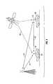
- FIG. 1is an overhead schematic view of a vehicle equipped with a contact avoidance system in accordance with one disclosed embodiment
- FIG. 2is a functional block diagram of a vehicle contact avoidance system in accordance with one disclosed embodiment
- FIG. 3is a functional block diagram of a modified vehicle contact avoidance system in accordance with a disclosed embodiment
- FIG. 4illustrates GPS and DRSC signal transmissions in accordance with a disclosed embodiment
- FIG. 5is a partial interior view of the host vehicle illustrating features of the warning system in accordance with one disclosed embodiment
- FIG. 6is a sound profile of an audible warning according to one disclosed embodiment
- FIG. 7is a flowchart illustrating steps executed by a controller according to a disclosed embodiment.
- FIGS. 8-10illustrate exemplary scenarios in which a contact avoidance system according to the disclosed embodiments is beneficial.
- a host vehicle 10includes contact avoidance system 12 in accordance with one embodiment.
- the contact avoidance system 12generally includes a controller or control unit 14 , a wireless communications device 16 , a warning system 18 , a host vehicle internal ambient noise sensor 20 , a plurality of obstacle sensors 22 , 24 , 26 , and 28 , and a host vehicle driving sensor 30 connected to the controller 14 .
- a global positioning system (GPS) 32 and a dedicated short-range communications antenna (DSRC) 34may be connected to the wireless communications device 16 .
- GPSglobal positioning system
- DSRCdedicated short-range communications antenna
- the system 12may include more components or elements or as few of the components listed above as desired.
- the control unit 14preferably includes a microcomputer with a control program that controls the contact avoidance system 12 as discussed below.
- the control unit 14can also include other conventional components such as an input interface circuit, an output interface circuit, and storage devices such as a ROM (Read Only Memory) device and a RAM (Random Access Memory) device.
- the microcomputer of the control unit 14is programmed to control the contact avoidance system.
- the memory circuitstores processing results and control programs that are run by the processor circuit.
- the control unit 14is operatively coupled to the wireless communications device 16 , the warning system 18 , the host vehicle internal ambient noise sensor 20 , the plurality of obstacle sensors 22 , 24 , 26 , and 28 , the host vehicle driving sensor 30 , the GPS 32 and the DSRC antenna 34 in a conventional manner.
- the internal RAM of the control unit 14stores statuses of operational flags and various control data.
- the internal ROM of the control unit 14stores the information or data for various operations.
- the control unit 14is capable of selectively controlling any of the components of the contact avoidance system 12 in accordance with the control program. It will be apparent to those skilled in the art from this disclosure that the precise structure and algorithms for the control unit 14 can be any combination of hardware and software that will carry out the functions of the disclosed embodiments.
- the controller 14is programmed to determine whether contact between the host vehicle 10 and the remote obstacle is imminent, and is further programmed to cause the warning system 18 to emit the warning sound based on a determination of whether contact with the remote obstacle is imminent.
- the plurality of obstacle sensors 22 , 24 , 26 , and 28define a detection system 31 configured to detect a remote obstacle in proximity to a host vehicle 10 .
- the obstacle sensorsare preferably mounted externally on the host vehicle 10 .
- the sensorsmay be mounted on any suitable external portion of the host vehicle 10 , including the front and rear quarter panels, the bumpers, the external mirrors or any combination of suitable areas.
- the front sensors 22 and 24can include a long-range radar device for object detection in front of the host vehicle 10 .
- the front sensors 22 and 24may be configured to detect objects at a predetermined distance (e.g., distances up to 200 m), and thus may have a narrow field of view angle (e.g., around 15°). Due to the narrow field of view angle, long range radar may not detect all objects in the front of the host vehicle 10 .
- the front corner sensors 22 and 24can include short-range radar devices to assist in monitoring the region in front of the host vehicle 10 , each having a 60° field of view angle and 40 m detection range in one embodiment.
- the rear sensors 26 and 28may include short-range radar devices to assist in monitoring oncoming traffic beside and behind the host vehicle 10 , each having a 60° field of view angle and 40 m detection range in one embodiment.
- Placement of the aforementioned sensorspermits monitoring of traffic flow including remote vehicles and other objects around the host vehicle 10 .
- the sensors 22 , 24 , 26 and 28can be disposed in any position on the host vehicle 10 and may include any type and/or combination of sensors.
- the sensorsmay be cameras, radar sensors, photo sensors or any combination thereof.
- FIGS. 1 and 2illustrate four sensors, there can be as few or as many sensors as desirable or suitable.
- the sensors 22 , 24 , 26 , and 28can be electronic detection devices that transmit either electromagnetic waves (e.g., radar) or take computer-processed images with a digital camera and analyze the images or emit lasers, as is known in the art.
- the sensorsmay be capable of detecting at least the speed, direction, yaw, acceleration and distance of the remote obstacle relative to the host vehicle 10 .
- the sensorsmay include object-locating sensing devices including range sensors, such as FM-CW (Frequency Modulated Continuous Wave) radars, pulse and FSK (Frequency Shift Keying) radars, and Lidar (Light Detection and Ranging) devices, and ultrasonic devices which rely upon effects such as Doppler-effect measurements to locate forward objects.
- FM-CWFrequency Modulated Continuous Wave
- FSKFrequency Shift Keying
- LidarLight Detection and Ranging
- Object-locating devicesmay include charged-coupled devices (CCD) or complementary metal oxide semi-conductor (CMOS) video image sensors, and other known camera/video image processors which utilize digital photographic methods to “view” forward objects including one or more remote obstacles.
- CCDcharged-coupled devices
- CMOScomplementary metal oxide semi-conductor
- the sensors 22 , 24 , 26 , and 28are in communication with the controller 14 and are capable of transmitting information to the controller 14 .
- the controller 14is programmed to determine if contact with the remote obstacle is imminent based on the information supplied by the detection system 31 .
- the detection system 31 ′can utilize the wireless communication system 16 and the DSRC antenna 34 in addition to or in place of the obstacle sensors 22 , 24 , 26 and 28 .
- the DSRC antenna 34communicates with the wireless communications device 16 .
- the communications device 16is coupled to the DSRC antenna 34 to receive 5.9 GHz DSRC signals 41 from the two-way wireless communications network 16 .
- These DSRC signalscan include basic safety messages (BSMs) that include information which, under certain circumstances, warns drivers of imminent vehicle contact in time for the driver of the host vehicle 10 to take appropriate action to avoid the vehicle contact.
- BSMsbasic safety messages
- a BSMincludes information in accordance with SAE Standard J2735 as can be appreciated by one skilled in the art.
- the host vehicle 10can receive BSM signals 43 from a remote vehicle 38 , including information pertaining to vehicle latitude, vehicle longitude, vehicle elevation, position accuracy, vehicle speed, vehicle heading, vehicle steering wheel angle, vehicle acceleration (e.g., lateral, longitudinal, vertical and yaw rate), vehicle brake status, vehicle size, vehicle location, vehicle heading and the vehicle intended next maneuver.
- the intended next maneuver of the remote vehicle 38can be determined based on a condition of a turn signal on the remote vehicle 38 .
- the intended next maneuver of the remote vehicle 38can be determined based on a set navigation route for the remote vehicle 38 that can be set by, for example, a navigation system of the remote vehicle 38 .
- the intended next maneuver of the remote vehicle 38can be determined as a straight movement of the remote vehicle 38 at an intersection, a left turn of the remote vehicle 38 at an intersection or a right turn of the remote vehicle 38 at an intersection.
- the systemmay include a BSM classification application capable of, for example, caching BSM messages received from one or more remote vehicles 38 in a cache table, which can also be referred to as a lookup table.
- the cache tablecan include information representing the remote vehicle intended next maneuver, the remote vehicle location, and any other suitable information included in the BSMs which can then be retrieved for use as discussed herein.
- the controller 14can receive and process BSMs from many remote vehicles 38 at the same time. For example, the controller 14 can receive and process BSMs from 100 remote vehicles 38 , or any other suitable number of remote vehicles 38 , at the same time.
- the controller 14can determine whether there is a possibility that remote vehicle 38 may contact the host vehicle 10 and thus represents a potential threat vehicle to the host vehicle 10 . If the remote vehicle 38 does not represent a threat, the controller 14 can, for example, discard the data included in the BSM. The controller 14 can also discard a BSM from the cache after a period of time, for example, 0.5 seconds or any suitable length of time.
- the host vehicle 10may have a vehicle driving sensor 22 .
- the vehicle driving sensor 22detects driving conditions of the host vehicle 10 , such as vehicle latitude, vehicle longitude, vehicle elevation, position accuracy, vehicle speed, vehicle heading, vehicle steering wheel angle, vehicle acceleration (e.g., lateral, longitudinal, vertical and yaw rate), vehicle brake status, vehicle size, and other aspects of the vehicle.
- the vehicle driving sensor 22can be any suitable sensor known in the art.
- the vehicle driving sensor 22can send or transmit this information to the controller 14 at periodic intervals (e.g., every 100 msec). Naturally, this information can include additional or fewer types of data as necessary or desired.
- the system 12may utilize a GPS 32 as illustrated in FIGS. 3 and 4 .
- the GPS 32preferably includes a GPS antenna 35 and a GPS receiver 36 .
- the GPS antenna 35communicates with the wireless communications device 16 .
- the host vehicle 10receives a GPS satellite signal 39 .
- the GPS 32processes the GPS satellite signal 39 to determine positional information (such as speed, acceleration, yaw, and direction, just to name a few) of the host vehicle 10 .
- the GPS antenna 35 and the DSRC antenna 34can be configured as a dual frequency DSRC and GPS antenna as understood in the art.
- the warning system 18is illustrated and preferably includes a sound device 40 (such as a speaker) mounted on the dashboard or instrument panel 42 , and is configured such that it will activate the warning sound upon receiving a signal from the controller 14 .
- the sound devicemay emanate the warning sound from speakers used for other applications (e.g., the radio) or from a dedicated speaker.
- the warning soundincludes a non-speech portion followed by a speech portion.
- the non-speech portion of the warning soundmay be a beep, a series of beeps, a horn, or any other suitable or combination of suitable non-speech sound warnings.
- auditory warningsare effective because they are noticeable regardless of the driver's eye position and because they have a relatively low implementation cost.
- the auditory warningsare digital files played from a sound generator, as discussed above, and are emitted from a dedicated speaker 40 or speakers mounted on the dashboard or the instrument panel near the driver; however, the auditory warning can be emitted from any suitable source, such as the audio system of the car.
- Activation of the soundsmay be controlled by the controller 14 (which can include a dedicated application ECU or electronic control unit) based on information received from a remote obstacle or from the sensors 22 , 24 , 26 and 28 .
- the auditory warninghas both a speech portion and a non-speech portion, the combination of which results in a signal length of about 0.6-1.7 seconds. It has been determined that such a length of sound enables perception and an appropriate time for reaction. However, any suitable length of warning and/or combination of speech and non-speech sounds may be used.
- the auditory warningis a single auditory warning; however, if desired the warning may be multiple auditory warnings.
- the non-speech portionis preferably a horn sound, which has been determined to be effective at obtaining a driver's attention, while simultaneously communicating urgency due to familiarity of the horn sound to the driver.
- the auditory warning in this embodimentincludes a speech portion or signal, since such speech signals may be effective at communicating a specific threat.
- the first portion of the auditory warningmay be a horn sound having a duration of about 0.4 to 0.8 seconds, and more preferably about 0.6 seconds
- the second portion of the auditory warningis a speech sound having a duration of about 0.4 to 0.8 seconds, and more preferably about 0.6 seconds.
- the preferable length of the auditory warningis less than or equal to 1.7 seconds.
- the length of each of the speech portion and non-speech portioncan be shorter or longer than 0.4 to 0.8 seconds, if desired.
- the sound level of the auditory warningis about 68-70 dB-A as measured with a hand held sound meter at about the drivers head position. This sound level is generally noticeable even when the car radio is set at a level of around 65 dB-A.
- the horn soundpreferably has a frequency that is different from a conventional horn and has broadband content (i.e., sound pressure content across all 1 ⁇ 3 octave bands); however, any desired horn sound may be utilized.
- a low pass filter 45shown in FIGS. 2 and 3 ) may be used to reduce the sound pressure content at 1 ⁇ 3 octave bands higher than 2500 Hz. It has been determined that 2500 Hz (2.5 kHz) and higher is most perceivable to people with average hearing capability.
- the low pass filter 45is preferably hardware in the controller 14 , but may be any suitable low pass filter.
- the speech portion of the auditory warningis preferably utilized to confirm the meaning of the horn signal. That is, the speech portion may be utilized to confirm that contact with an obstacle is possible.
- the spoken word “warning”may be used; however, any suitable word may be used.
- the spoken wordis generated by a text-to-speech program using a computer-generated female voice; however, any gender voice may be utilized and the voice may be a recording or generated in any suitable manner. It has been determined that the speech portion preferred length of about 0.6 seconds is long enough for a two syllable word to be perceived, but is also brief enough to quickly communicate urgency. This results in a combined audible warning (speech portion and non-speech portion) having a total length of about 1.7 seconds or less.
- the warning system 18may include a visual display or indicator 44 that flashes or illuminates on the instrument cluster 42 of the host vehicle 10 , illuminates in a heads-up display, is a visual readout 46 on an information display unit 48 , or any other suitable visual display or indicator 44 that notifies the driver or interior occupant of the host vehicle 10 that contact with a remote obstacle is possible.
- the warningmay also include tactile feedback generated by a vibration actuator in the steering wheel 49 , the driver seat or any other suitable location within the host vehicle 10 .
- an internal noise sensor 20may be utilized.
- the internal ambient noise sensor 20determines the internal noise level of the vehicle.
- the internal noise sensor 20detects and indicates this to the controller 14 .
- the controller 14can then adjust the decibel level of the warning indicator to be heard above the ambient noise level.
- the controller 14activates the warning sound 3-5 dB louder than the ambient noise detected by the internal ambient noise sensor 20 .
- the internal ambient noise sensor 20can be any suitable sensor known in the art.
- the systemwhen determining whether to activate the warning, the system starts the process at step 50 .
- the systemdetects or determines if a remote obstacle is present in the vicinity of the host vehicle 10 at step 52 . As stated above, such a determination is made using the detection system 31 or 31 ′. If there is no obstacle detected, the system starts the process again. If an obstacle is detected, the detection system 31 communicates relevant information to the controller 14 . That is, the detection system 31 communicates at least one of the speed, direction, yaw and acceleration of the host vehicle 10 (or any other suitable or desired information) to the controller 14 at step 54 .
- this informationcan be determined based on feedback from the on-board vehicle driving sensors 22 and/or information received by the DSRC antenna 34 .
- the systemdetermines the speed, direction, yaw and acceleration of the remote obstacle at step 56 .
- this determinationmay be made by the on board driving sensors 30 and/or the GPS 32 .
- the controller 14uses the information regarding the remote obstacle and the host vehicle 10 to determine if contact between the host vehicle 10 and the remote obstacle is imminent at step 58 . Such a determination can be made using known calculations based on at least the speed, direction, acceleration and yaw of the host vehicle 10 and the remote obstacle (or any other suitable or desired information).
- the systemIf the controller 14 determines that contact is not imminent, the system restarts and determines if a remote obstacle is present. If the controller 14 determines that contact is imminent, the system activates the warning at step 60 .
- the warningis preferably an audible warning that includes both a non-speech portion and a speech portion.
- the controller 14causes the warning system 18 to activate the warning sound at 3-5 dB higher than any detected ambient noise. Further, as discussed in one embodiment, a light and/or tactile warning can be activated in addition to the sound warning.
- FIG. 8illustrates a scenario in which the host vehicle 10 is turning left across a lane in which the remote vehicle 38 is traveling.
- the detection system 31 of the host vehicle 10would detect the presence of the remote vehicle 38 .
- the controller 14determines whether contact between the host vehicle 10 and the remote vehicle 38 is imminent. As discussed above, such a determination may be based on feedback from the host vehicle driving sensor 30 and/or GPS 32 , feedback from the obstacle sensors 22 , 24 , 26 , and 28 and/or data received by the DSRC antenna 34 . If a determination is made that no contact is imminent, no warning is activated.
- the controller 14determines that contact is imminent, the controller 14 causes the warning system 18 to emit the warning, which preferably includes a non-speech portion (e.g. a horn) followed by a speech portion (e.g., a voice stating “warning”).
- a non-speech portione.g. a horn
- a speech portione.g., a voice stating “warning”.
- FIG. 9illustrates a scenario in which the host vehicle 10 is turning left at an intersection and the remote vehicle 38 is traveling in a direction transverse to the host vehicle 10 .
- the detection system 31 of the host vehicle 10would detect the presence of the remote vehicle 38 .
- the controller 14determines whether contact between the host vehicle 10 and the remote vehicle 38 is imminent. As discussed above, such a determination may be based on feedback from the host vehicle driving sensor 30 and/or GPS 32 , feedback from the obstacle sensors 22 , 24 , 26 , and 28 and/or data received by the DSRC antenna 34 . If a determination is made that no contact is imminent, no warning is activated.
- the controller 14determines that contact is imminent, the controller 14 causes the warning system 18 to emit the warning, which preferably includes a non-speech portion (e.g. a horn) followed by a speech portion (e.g., a voice stating “warning”).
- a non-speech portione.g. a horn
- a speech portione.g., a voice stating “warning”.
- FIG. 10illustrates a scenario in which the host vehicle 10 is traveling across an intersection and the remote vehicle 38 is traveling in a direction transverse to the host vehicle 10 .
- the detection system 31 of the host vehicle 10would detect the presence of the remote vehicle 38 .
- the controller 14determines whether contact between the host vehicle 10 and the remote vehicle 38 is imminent. As discussed above, such a determination may be based on feedback from the host vehicle driving sensor 30 and/or GPS 32 , feedback from the obstacle sensors 22 , 24 , 26 , and 28 and/or data received by the DSRC antenna 34 . If a determination is made that no contact is imminent, no warning is activated.
- the controller 14determines that contact is imminent, the controller 14 causes the warning system 18 to emit the warning, which preferably includes a non-speech portion (e.g. a horn) followed by a speech portion (e.g., a voice stating “warning”).
- a non-speech portione.g. a horn
- a speech portione.g., a voice stating “warning”.
- the term “comprising” and its derivatives, as used herein,are intended to be open ended terms that specify the presence of the stated features, elements, components, groups, integers, and/or steps, but do not exclude the presence of other unstated features, elements, components, groups, integers and/or steps.
- the foregoingalso applies to words having similar meanings such as the terms, “including”, “having” and their derivatives.
- the terms “part,” “section,” “portion,” or “element” when used in the singularcan have the dual meaning of a single part or a plurality of parts.
- the following directional terms “front”, “rear”, “vertical”, “horizontal”, “below” and “transverse” as well as any other similar directional termsrefer to those directions of a vehicle equipped with the vehicle contact avoidance system. Accordingly, these terms, as utilized to describe the present invention should be interpreted relative to a vehicle equipped with the vehicle contact avoidance system.
- detectas used herein to describe an operation or function carried out by a component, a section, a device or the like includes a component, a section, a device or the like that does not require physical detection, but rather includes determining, measuring, modeling, predicting or computing or the like to carry out the operation or function.
Landscapes
- Physics & Mathematics (AREA)
- General Physics & Mathematics (AREA)
- Engineering & Computer Science (AREA)
- Electromagnetism (AREA)
- Human Computer Interaction (AREA)
- Mechanical Engineering (AREA)
- Business, Economics & Management (AREA)
- Emergency Management (AREA)
- Traffic Control Systems (AREA)
Abstract
Description
Claims (18)
Priority Applications (1)
| Application Number | Priority Date | Filing Date | Title |
|---|---|---|---|
| US14/070,356US9177478B2 (en) | 2013-11-01 | 2013-11-01 | Vehicle contact avoidance system |
Applications Claiming Priority (1)
| Application Number | Priority Date | Filing Date | Title |
|---|---|---|---|
| US14/070,356US9177478B2 (en) | 2013-11-01 | 2013-11-01 | Vehicle contact avoidance system |
Publications (2)
| Publication Number | Publication Date |
|---|---|
| US20150123778A1 US20150123778A1 (en) | 2015-05-07 |
| US9177478B2true US9177478B2 (en) | 2015-11-03 |
Family
ID=53006628
Family Applications (1)
| Application Number | Title | Priority Date | Filing Date |
|---|---|---|---|
| US14/070,356Active2034-01-11US9177478B2 (en) | 2013-11-01 | 2013-11-01 | Vehicle contact avoidance system |
Country Status (1)
| Country | Link |
|---|---|
| US (1) | US9177478B2 (en) |
Cited By (3)
| Publication number | Priority date | Publication date | Assignee | Title |
|---|---|---|---|---|
| US20160224025A1 (en)* | 2013-09-09 | 2016-08-04 | Valeo Comfort And Driving Assistance | Method for making a remotely operated control of a motor vehicle secure using a mobile terminal |
| US9445308B2 (en)* | 2012-06-14 | 2016-09-13 | Continental Automotive Gmbh | Method for verifying and/or preprocessing data packets and control device set up to carry out the method |
| CN109949610A (en)* | 2017-12-11 | 2019-06-28 | 罗伯特·博世有限公司 | Intersect traffic auxiliary and control |
Families Citing this family (20)
| Publication number | Priority date | Publication date | Assignee | Title |
|---|---|---|---|---|
| US10086699B2 (en) | 2015-06-24 | 2018-10-02 | Nissan North America, Inc. | Vehicle operation assistance information management for autonomous vehicle control operation |
| US9630498B2 (en) | 2015-06-24 | 2017-04-25 | Nissan North America, Inc. | Vehicle operation assistance information management |
| US9937795B2 (en) | 2015-06-24 | 2018-04-10 | Nissan North America, Inc. | Vehicle operation assistance information management for autonomous vehicle control transfer |
| US20170327035A1 (en)* | 2016-05-10 | 2017-11-16 | Ford Global Technologies, Llc | Methods and systems for beyond-the-horizon threat indication for vehicles |
| DE102016218344A1 (en)* | 2016-09-23 | 2018-03-29 | Conti Temic Microelectronic Gmbh | Apparatus and method for adjusting the time interval between successive warnings |
| CN106846908B (en)* | 2016-12-27 | 2020-08-07 | 东软集团股份有限公司 | Road danger judgment method and device |
| JP6796798B2 (en)* | 2017-01-23 | 2020-12-09 | パナソニックIpマネジメント株式会社 | Event prediction system, event prediction method, program, and mobile |
| US20200031227A1 (en)* | 2017-03-29 | 2020-01-30 | Mitsubishi Electric Corporation | Display control apparatus and method for controlling display |
| WO2020013796A1 (en)* | 2018-07-12 | 2020-01-16 | Dish Ukraine L.L.C. | Vehicle to vehicle event notification system and method |
| US11697410B2 (en)* | 2019-03-07 | 2023-07-11 | Toyota Jidosha Kabushiki Kaisha | Vehicle-to-everything communication-based lane change collision avoidance warning |
| US11287266B2 (en) | 2019-03-13 | 2022-03-29 | Here Global B.V. | Maplets for maintaining and updating a self-healing high definition map |
| US11096026B2 (en)* | 2019-03-13 | 2021-08-17 | Here Global B.V. | Road network change detection and local propagation of detected change |
| US11280622B2 (en) | 2019-03-13 | 2022-03-22 | Here Global B.V. | Maplets for maintaining and updating a self-healing high definition map |
| US11255680B2 (en) | 2019-03-13 | 2022-02-22 | Here Global B.V. | Maplets for maintaining and updating a self-healing high definition map |
| US11287267B2 (en) | 2019-03-13 | 2022-03-29 | Here Global B.V. | Maplets for maintaining and updating a self-healing high definition map |
| US11402220B2 (en) | 2019-03-13 | 2022-08-02 | Here Global B.V. | Maplets for maintaining and updating a self-healing high definition map |
| US11001200B2 (en)* | 2019-05-30 | 2021-05-11 | Nissan North America, Inc. | Vehicle occupant warning system |
| KR102854804B1 (en)* | 2019-06-17 | 2025-09-04 | 현대자동차주식회사 | Sound communication system and method for transmitting and receiving data thereof |
| US11711680B2 (en)* | 2020-06-09 | 2023-07-25 | Qualcomm Incorporated | Vehicle-to-vehicle maneuver sharing and coordinating |
| US11673570B2 (en)* | 2021-04-26 | 2023-06-13 | Nissan North America, Inc. | Vehicle driving behavior monitoring and warning system |
Citations (47)
| Publication number | Priority date | Publication date | Assignee | Title |
|---|---|---|---|---|
| US4352088A (en) | 1979-07-16 | 1982-09-28 | Nissan Motor Company, Limited | Voice warning system for an automotive vehicle |
| JPS59102634A (en) | 1982-12-02 | 1984-06-13 | Matsushita Electric Ind Co Ltd | Vehicle warning device |
| JPS61253238A (en) | 1985-04-15 | 1986-11-11 | Stanley Electric Co Ltd | Speed warning device using voice synthesis |
| US4644327A (en) | 1982-07-30 | 1987-02-17 | National Research Development Corp. | Methods for generating auditory indicators |
| US4706072A (en) | 1983-11-30 | 1987-11-10 | Aisin Seiki Kabushiki Kaisha | Human condition monitoring and security controlling apparatus on a road-vehicle |
| US4903291A (en)* | 1986-10-09 | 1990-02-20 | Sanyo Electric Co., Ltd. | Automatic on-hook arrangement |
| US5620155A (en)* | 1995-03-23 | 1997-04-15 | Michalek; Jan K. | Railway train signalling system for remotely operating warning devices at crossings and for receiving warning device operational information |
| US5788336A (en) | 1993-07-14 | 1998-08-04 | Philips Electronics North America Corporation | Anti-lock brake warning system |
| US5845250A (en) | 1995-06-02 | 1998-12-01 | U.S. Philips Corporation | Device for generating announcement information with coded items that have a prosody indicator, a vehicle provided with such device, and an encoding device for use in a system for generating such announcement information |
| US5940010A (en) | 1997-07-31 | 1999-08-17 | Toyota Jidosha Kabushiki Kaisha | Intersection warning system |
| US5939976A (en) | 1997-07-31 | 1999-08-17 | Toyota Jidosha Kabushiki Kaisha, Hino Jidosha Kogyo Kabushiki Kaisha, Aisin Seiki Kabushiki Kaisha, And Denso Corporation | Intersection warning system |
| US5979586A (en)* | 1997-02-05 | 1999-11-09 | Automotive Systems Laboratory, Inc. | Vehicle collision warning system |
| US6008741A (en) | 1997-09-30 | 1999-12-28 | Toyota Jidosha Kabushiki Kaisha | Intersection information supply apparatus |
| JP2000127796A (en) | 1998-10-21 | 2000-05-09 | Matsushita Electric Ind Co Ltd | In-vehicle alarm device and in-vehicle alarm method |
| JP2001118199A (en) | 1999-10-18 | 2001-04-27 | Nec Corp | Method and system for warning danger of collision at crossing, on-vehicle device, traffic controller and recording medium |
| US6259992B1 (en)* | 1998-06-03 | 2001-07-10 | Honda Giken Kogyo Kabushiki Kaisha | Vehicle safety running control system |
| US6294987B1 (en)* | 1998-05-07 | 2001-09-25 | Honda Giken Kogyo Kabushiki Kaisha | Vehicle safety running control system |
| US6366207B1 (en) | 2000-02-04 | 2002-04-02 | Michael Murphy | Device for modifying vehicle operator driving behavior |
| JP2003051099A (en) | 2001-08-07 | 2003-02-21 | Matsushita Electric Ind Co Ltd | Traffic control system |
| US6615137B2 (en)* | 2001-06-26 | 2003-09-02 | Medius, Inc. | Method and apparatus for transferring information between vehicles |
| WO2003091966A1 (en) | 2002-04-24 | 2003-11-06 | Mohammed El Ouakifi | Remote-controlled intelligent traffic signalling |
| US6700504B1 (en) | 2000-11-01 | 2004-03-02 | Navigation Technologies Corp. | Method and system for safe emergency vehicle operation using route calculation |
| US6720898B1 (en) | 2003-04-10 | 2004-04-13 | Maxim Integrated Products, Inc. | Current source array for high speed, high resolution current steering DACs |
| US6791471B2 (en) | 2002-10-01 | 2004-09-14 | Electric Data Systems | Communicating position information between vehicles |
| US6810328B2 (en) | 2002-11-23 | 2004-10-26 | Alpine Electronics, Inc | Navigation method and system for indicating area-specific traffic information |
| US20070103276A1 (en)* | 2005-11-08 | 2007-05-10 | Autonetworks Technologies, Ltd. | Sound production controller |
| US7274288B2 (en) | 2004-06-30 | 2007-09-25 | Denso Corporation | Vehicle alarm sound outputting device and program |
| EP1962255A1 (en) | 2007-02-20 | 2008-08-27 | Robert Bosch Gmbh | Control device and method for reproducing an acoustic warning signal |
| US20090033540A1 (en) | 1997-10-22 | 2009-02-05 | Intelligent Technologies International, Inc. | Accident Avoidance Systems and Methods |
| US20090140887A1 (en) | 2007-11-29 | 2009-06-04 | Breed David S | Mapping Techniques Using Probe Vehicles |
| US20090198412A1 (en) | 2008-02-04 | 2009-08-06 | Denso Corporation | Vehicle-to-vehicle communications apparatus |
| US20100169009A1 (en) | 1997-10-22 | 2010-07-01 | Intelligent Technologies International, Inc. | Accident Avoidance System |
| US8000897B2 (en) | 1997-10-22 | 2011-08-16 | Intelligent Technologies International, Inc. | Intersection collision avoidance techniques |
| US20120016581A1 (en) | 2010-07-19 | 2012-01-19 | Honda Motor Co., Ltd. | Collision Warning System Using Driver Intention Estimator |
| US8175796B1 (en) | 2008-09-25 | 2012-05-08 | The United States Of America As Represented By The Secretary Of The Navy | Method for vehicle collision avoidance |
| US20120218093A1 (en) | 2009-10-30 | 2012-08-30 | Toyota Jidosha Kabushiki Kaisha | Driving support device |
| US8340894B2 (en) | 2009-10-08 | 2012-12-25 | Honda Motor Co., Ltd. | Method of dynamic intersection mapping |
| US20130116915A1 (en) | 2010-07-16 | 2013-05-09 | Universidade Do Porto | Methods and Systems For Coordinating Vehicular Traffic Using In-Vehicle Virtual Traffic Control Signals Enabled By Vehicle-To-Vehicle Communications |
| US8466807B2 (en) | 2011-06-01 | 2013-06-18 | GM Global Technology Operations LLC | Fast collision detection technique for connected autonomous and manual vehicles |
| US20130179047A1 (en) | 2012-01-10 | 2013-07-11 | Ford Global Technologies, Llc | Intersection collision avoidance with adaptable vehicle dimensions |
| US8548729B2 (en) | 2009-11-19 | 2013-10-01 | Sanyo Electric Co., Ltd. | Radio apparatus mounted on a vehicle |
| US20130268184A1 (en)* | 2012-04-05 | 2013-10-10 | GM Global Technology Operations LLC | Target vehicle movement classification |
| US20130278440A1 (en) | 2012-04-24 | 2013-10-24 | Zetta Research and Development, LLC - ForC Series | Anti-collision system and method using message formats containing distances |
| US8577550B2 (en) | 2009-10-05 | 2013-11-05 | Ford Global Technologies, Llc | System for vehicle control to mitigate intersection collisions and method of using the same |
| US8587418B2 (en) | 2010-07-28 | 2013-11-19 | Honda Motor Co., Ltd. | Method of controlling a collision warning system using right of way |
| US8639426B2 (en) | 2010-07-15 | 2014-01-28 | George C Dedes | GPS/IMU/video/radar absolute/relative positioning communication/computation sensor platform for automotive safety applications |
| US8717192B2 (en)* | 2010-10-08 | 2014-05-06 | Navteq B.V. | Method and system for using intersecting electronic horizons |
- 2013
- 2013-11-01USUS14/070,356patent/US9177478B2/enactiveActive
Patent Citations (47)
| Publication number | Priority date | Publication date | Assignee | Title |
|---|---|---|---|---|
| US4352088A (en) | 1979-07-16 | 1982-09-28 | Nissan Motor Company, Limited | Voice warning system for an automotive vehicle |
| US4644327A (en) | 1982-07-30 | 1987-02-17 | National Research Development Corp. | Methods for generating auditory indicators |
| JPS59102634A (en) | 1982-12-02 | 1984-06-13 | Matsushita Electric Ind Co Ltd | Vehicle warning device |
| US4706072A (en) | 1983-11-30 | 1987-11-10 | Aisin Seiki Kabushiki Kaisha | Human condition monitoring and security controlling apparatus on a road-vehicle |
| JPS61253238A (en) | 1985-04-15 | 1986-11-11 | Stanley Electric Co Ltd | Speed warning device using voice synthesis |
| US4903291A (en)* | 1986-10-09 | 1990-02-20 | Sanyo Electric Co., Ltd. | Automatic on-hook arrangement |
| US5788336A (en) | 1993-07-14 | 1998-08-04 | Philips Electronics North America Corporation | Anti-lock brake warning system |
| US5620155A (en)* | 1995-03-23 | 1997-04-15 | Michalek; Jan K. | Railway train signalling system for remotely operating warning devices at crossings and for receiving warning device operational information |
| US5845250A (en) | 1995-06-02 | 1998-12-01 | U.S. Philips Corporation | Device for generating announcement information with coded items that have a prosody indicator, a vehicle provided with such device, and an encoding device for use in a system for generating such announcement information |
| US5979586A (en)* | 1997-02-05 | 1999-11-09 | Automotive Systems Laboratory, Inc. | Vehicle collision warning system |
| US5940010A (en) | 1997-07-31 | 1999-08-17 | Toyota Jidosha Kabushiki Kaisha | Intersection warning system |
| US5939976A (en) | 1997-07-31 | 1999-08-17 | Toyota Jidosha Kabushiki Kaisha, Hino Jidosha Kogyo Kabushiki Kaisha, Aisin Seiki Kabushiki Kaisha, And Denso Corporation | Intersection warning system |
| US6008741A (en) | 1997-09-30 | 1999-12-28 | Toyota Jidosha Kabushiki Kaisha | Intersection information supply apparatus |
| US20090033540A1 (en) | 1997-10-22 | 2009-02-05 | Intelligent Technologies International, Inc. | Accident Avoidance Systems and Methods |
| US20100169009A1 (en) | 1997-10-22 | 2010-07-01 | Intelligent Technologies International, Inc. | Accident Avoidance System |
| US8000897B2 (en) | 1997-10-22 | 2011-08-16 | Intelligent Technologies International, Inc. | Intersection collision avoidance techniques |
| US6294987B1 (en)* | 1998-05-07 | 2001-09-25 | Honda Giken Kogyo Kabushiki Kaisha | Vehicle safety running control system |
| US6259992B1 (en)* | 1998-06-03 | 2001-07-10 | Honda Giken Kogyo Kabushiki Kaisha | Vehicle safety running control system |
| JP2000127796A (en) | 1998-10-21 | 2000-05-09 | Matsushita Electric Ind Co Ltd | In-vehicle alarm device and in-vehicle alarm method |
| JP2001118199A (en) | 1999-10-18 | 2001-04-27 | Nec Corp | Method and system for warning danger of collision at crossing, on-vehicle device, traffic controller and recording medium |
| US6366207B1 (en) | 2000-02-04 | 2002-04-02 | Michael Murphy | Device for modifying vehicle operator driving behavior |
| US6700504B1 (en) | 2000-11-01 | 2004-03-02 | Navigation Technologies Corp. | Method and system for safe emergency vehicle operation using route calculation |
| US6615137B2 (en)* | 2001-06-26 | 2003-09-02 | Medius, Inc. | Method and apparatus for transferring information between vehicles |
| JP2003051099A (en) | 2001-08-07 | 2003-02-21 | Matsushita Electric Ind Co Ltd | Traffic control system |
| WO2003091966A1 (en) | 2002-04-24 | 2003-11-06 | Mohammed El Ouakifi | Remote-controlled intelligent traffic signalling |
| US6791471B2 (en) | 2002-10-01 | 2004-09-14 | Electric Data Systems | Communicating position information between vehicles |
| US6810328B2 (en) | 2002-11-23 | 2004-10-26 | Alpine Electronics, Inc | Navigation method and system for indicating area-specific traffic information |
| US6720898B1 (en) | 2003-04-10 | 2004-04-13 | Maxim Integrated Products, Inc. | Current source array for high speed, high resolution current steering DACs |
| US7274288B2 (en) | 2004-06-30 | 2007-09-25 | Denso Corporation | Vehicle alarm sound outputting device and program |
| US20070103276A1 (en)* | 2005-11-08 | 2007-05-10 | Autonetworks Technologies, Ltd. | Sound production controller |
| EP1962255A1 (en) | 2007-02-20 | 2008-08-27 | Robert Bosch Gmbh | Control device and method for reproducing an acoustic warning signal |
| US20090140887A1 (en) | 2007-11-29 | 2009-06-04 | Breed David S | Mapping Techniques Using Probe Vehicles |
| US20090198412A1 (en) | 2008-02-04 | 2009-08-06 | Denso Corporation | Vehicle-to-vehicle communications apparatus |
| US8175796B1 (en) | 2008-09-25 | 2012-05-08 | The United States Of America As Represented By The Secretary Of The Navy | Method for vehicle collision avoidance |
| US8577550B2 (en) | 2009-10-05 | 2013-11-05 | Ford Global Technologies, Llc | System for vehicle control to mitigate intersection collisions and method of using the same |
| US8340894B2 (en) | 2009-10-08 | 2012-12-25 | Honda Motor Co., Ltd. | Method of dynamic intersection mapping |
| US20120218093A1 (en) | 2009-10-30 | 2012-08-30 | Toyota Jidosha Kabushiki Kaisha | Driving support device |
| US8548729B2 (en) | 2009-11-19 | 2013-10-01 | Sanyo Electric Co., Ltd. | Radio apparatus mounted on a vehicle |
| US8639426B2 (en) | 2010-07-15 | 2014-01-28 | George C Dedes | GPS/IMU/video/radar absolute/relative positioning communication/computation sensor platform for automotive safety applications |
| US20130116915A1 (en) | 2010-07-16 | 2013-05-09 | Universidade Do Porto | Methods and Systems For Coordinating Vehicular Traffic Using In-Vehicle Virtual Traffic Control Signals Enabled By Vehicle-To-Vehicle Communications |
| US20120016581A1 (en) | 2010-07-19 | 2012-01-19 | Honda Motor Co., Ltd. | Collision Warning System Using Driver Intention Estimator |
| US8587418B2 (en) | 2010-07-28 | 2013-11-19 | Honda Motor Co., Ltd. | Method of controlling a collision warning system using right of way |
| US8717192B2 (en)* | 2010-10-08 | 2014-05-06 | Navteq B.V. | Method and system for using intersecting electronic horizons |
| US8466807B2 (en) | 2011-06-01 | 2013-06-18 | GM Global Technology Operations LLC | Fast collision detection technique for connected autonomous and manual vehicles |
| US20130179047A1 (en) | 2012-01-10 | 2013-07-11 | Ford Global Technologies, Llc | Intersection collision avoidance with adaptable vehicle dimensions |
| US20130268184A1 (en)* | 2012-04-05 | 2013-10-10 | GM Global Technology Operations LLC | Target vehicle movement classification |
| US20130278440A1 (en) | 2012-04-24 | 2013-10-24 | Zetta Research and Development, LLC - ForC Series | Anti-collision system and method using message formats containing distances |
Non-Patent Citations (9)
| Title |
|---|
| Driver Focus-Telematics Working Group, Statement of Principles, Criteria and Verification Procedures on Driver Interactions with Advanced In-vehicle Information and Communication Systems (Version 2.0, 2002). |
| John Jacob Winters, An Investigation of Auditory Icons and Brake Response Times in a Commercial Truck-Cab Environment (Virginia Polytechnic Institute and State Univ. 1998). |
| John L. Campbell et al., Comprehension Testing of Active Safety Symbols (SAE International 2004). |
| Kathleen A. Harber, John Bloomfield, and Benjamin J. Chibak, The Effectiveness of Auditory Side- and Forward-Collision Avoidance Warnings in Winter Driving Conditions (Minnesota Department of Transportation, Report No. MN/RC 2003-14,2003). |
| Kurt, Arda (dissertation), "Hybrid-state system modelling for control, estimation and prediction in vehicular autonomy", presented in Partial Fulfillment of the Requirements for the Degree Doctor of Philosophy in the Graduate School of The Ohio State University, Mar. 2012, UMI/Proquest Pub. No. 3497707, 136 pages (total). |
| Kurt, Arda et al., "Hybrid-state driver/vehicle modelling, estimation and prediction", 13th International IEEE Annual Conference on Intelligent Transportation Systems, Madeira Island, Portugal, Paper TA3.4, Sep. 19-22, 2010, pp. 806-811. |
| M.L. Cummings et al., Effects of Single versus Multiple Warnings on Driver Performance (Human Factors and Ergonomics Society 2011). |
| Michael A. Nees & Bruce N. Walker, Auditory Displays for In-vehicle Technologies (Human Factors and Ergonomics Society 2011). |
| Pontus Larsson et al., Emotional and Behavioral Response to Auditory Icons and Earcons in Driver-vehicle Interfaces (Sweden, Paper No. 09-0104). |
Cited By (4)
| Publication number | Priority date | Publication date | Assignee | Title |
|---|---|---|---|---|
| US9445308B2 (en)* | 2012-06-14 | 2016-09-13 | Continental Automotive Gmbh | Method for verifying and/or preprocessing data packets and control device set up to carry out the method |
| US20160224025A1 (en)* | 2013-09-09 | 2016-08-04 | Valeo Comfort And Driving Assistance | Method for making a remotely operated control of a motor vehicle secure using a mobile terminal |
| US9846431B2 (en)* | 2013-09-09 | 2017-12-19 | Valeo Comfort And Driving Assistance | Method for making a remotely operated control of a motor vehicle secure using a mobile terminal |
| CN109949610A (en)* | 2017-12-11 | 2019-06-28 | 罗伯特·博世有限公司 | Intersect traffic auxiliary and control |
Also Published As
| Publication number | Publication date |
|---|---|
| US20150123778A1 (en) | 2015-05-07 |
Similar Documents
| Publication | Publication Date | Title |
|---|---|---|
| US9177478B2 (en) | Vehicle contact avoidance system | |
| JP7115270B2 (en) | Autonomous driving system | |
| US10625742B2 (en) | System and method for vehicle control in tailgating situations | |
| US10737667B2 (en) | System and method for vehicle control in tailgating situations | |
| KR102797059B1 (en) | Vehicle and method for controlling thereof | |
| US9824584B2 (en) | Driving support apparatus for vehicle | |
| US9020728B2 (en) | Vehicle turn monitoring system and method | |
| US9349291B2 (en) | Vehicle intersection monitoring system and method | |
| KR20210083462A (en) | Advanced Driver Assistance System, Vehicle having the same and method for controlling the vehicle | |
| US20180096601A1 (en) | Collision alert system | |
| US12246714B2 (en) | Advanced driver assistance system, and vehicle having the same | |
| US8946990B1 (en) | Vehicle headlight detection system | |
| US11999370B2 (en) | Automated vehicle system | |
| JP7151495B2 (en) | Autonomous driving system | |
| JP2007333486A (en) | Obstacle detector for vehicle | |
| JP5716700B2 (en) | Driving assistance device | |
| JP7150247B2 (en) | vehicle alarm system | |
| CN116323366A (en) | Method, device and computer-readable storage medium for providing three-dimensional stereo sound | |
| JP2008062666A (en) | Vehicle alarm device | |
| EP3576072A1 (en) | Alarm system for vehicle | |
| US20170059703A1 (en) | System for use in a vehicle | |
| US11001200B2 (en) | Vehicle occupant warning system | |
| JP2006315489A (en) | Vehicle surrounding alarm device | |
| KR101747818B1 (en) | Intelligent alarm apparatus of vehicle and method of the same | |
| CN115158300A (en) | Driving support device |
Legal Events
| Date | Code | Title | Description |
|---|---|---|---|
| AS | Assignment | Owner name:NISSAN NORTH AMERICA, INC., TENNESSEE Free format text:ASSIGNMENT OF ASSIGNORS INTEREST;ASSIGNORS:KONET, HEATHER;PROBERT, NEAL;CHAMBERS, JEREMY;AND OTHERS;REEL/FRAME:031532/0580 Effective date:20131031 | |
| STCF | Information on status: patent grant | Free format text:PATENTED CASE | |
| AS | Assignment | Owner name:NISSAN MOTOR CO., LTD., JAPAN Free format text:ASSIGNMENT OF ASSIGNORS INTEREST;ASSIGNOR:NISSAN NORTH AMERICA, INC.;REEL/FRAME:038059/0146 Effective date:20160308 | |
| AS | Assignment | Owner name:NISSAN NORTH AMERICA, INC., TENNESSEE Free format text:ASSIGNMENT OF ASSIGNORS INTEREST;ASSIGNOR:JOHNSON, BARBARA;REEL/FRAME:045134/0102 Effective date:20180301 | |
| CC | Certificate of correction | ||
| MAFP | Maintenance fee payment | Free format text:PAYMENT OF MAINTENANCE FEE, 4TH YEAR, LARGE ENTITY (ORIGINAL EVENT CODE: M1551); ENTITY STATUS OF PATENT OWNER: LARGE ENTITY Year of fee payment:4 | |
| MAFP | Maintenance fee payment | Free format text:PAYMENT OF MAINTENANCE FEE, 8TH YEAR, LARGE ENTITY (ORIGINAL EVENT CODE: M1552); ENTITY STATUS OF PATENT OWNER: LARGE ENTITY Year of fee payment:8 |