US9173748B2 - Toroid-shaped spinal disc - Google Patents
Toroid-shaped spinal discDownload PDFInfo
- Publication number
- US9173748B2 US9173748B2US12/839,491US83949110AUS9173748B2US 9173748 B2US9173748 B2US 9173748B2US 83949110 AUS83949110 AUS 83949110AUS 9173748 B2US9173748 B2US 9173748B2
- Authority
- US
- United States
- Prior art keywords
- component
- articulating surface
- intervertebral implant
- generally
- articulating
- Prior art date
- Legal status (The legal status is an assumption and is not a legal conclusion. Google has not performed a legal analysis and makes no representation as to the accuracy of the status listed.)
- Active, expires
Links
Images


Classifications
- A—HUMAN NECESSITIES
- A61—MEDICAL OR VETERINARY SCIENCE; HYGIENE
- A61F—FILTERS IMPLANTABLE INTO BLOOD VESSELS; PROSTHESES; DEVICES PROVIDING PATENCY TO, OR PREVENTING COLLAPSING OF, TUBULAR STRUCTURES OF THE BODY, e.g. STENTS; ORTHOPAEDIC, NURSING OR CONTRACEPTIVE DEVICES; FOMENTATION; TREATMENT OR PROTECTION OF EYES OR EARS; BANDAGES, DRESSINGS OR ABSORBENT PADS; FIRST-AID KITS
- A61F2/00—Filters implantable into blood vessels; Prostheses, i.e. artificial substitutes or replacements for parts of the body; Appliances for connecting them with the body; Devices providing patency to, or preventing collapsing of, tubular structures of the body, e.g. stents
- A61F2/02—Prostheses implantable into the body
- A61F2/30—Joints
- A61F2/44—Joints for the spine, e.g. vertebrae, spinal discs
- A61F2/442—Intervertebral or spinal discs, e.g. resilient
- A61F2/4425—Intervertebral or spinal discs, e.g. resilient made of articulated components
- A—HUMAN NECESSITIES
- A61—MEDICAL OR VETERINARY SCIENCE; HYGIENE
- A61F—FILTERS IMPLANTABLE INTO BLOOD VESSELS; PROSTHESES; DEVICES PROVIDING PATENCY TO, OR PREVENTING COLLAPSING OF, TUBULAR STRUCTURES OF THE BODY, e.g. STENTS; ORTHOPAEDIC, NURSING OR CONTRACEPTIVE DEVICES; FOMENTATION; TREATMENT OR PROTECTION OF EYES OR EARS; BANDAGES, DRESSINGS OR ABSORBENT PADS; FIRST-AID KITS
- A61F2/00—Filters implantable into blood vessels; Prostheses, i.e. artificial substitutes or replacements for parts of the body; Appliances for connecting them with the body; Devices providing patency to, or preventing collapsing of, tubular structures of the body, e.g. stents
- A61F2/02—Prostheses implantable into the body
- A61F2/30—Joints
- A61F2002/30001—Additional features of subject-matter classified in A61F2/28, A61F2/30 and subgroups thereof
- A61F2002/30003—Material related properties of the prosthesis or of a coating on the prosthesis
- A61F2002/30004—Material related properties of the prosthesis or of a coating on the prosthesis the prosthesis being made from materials having different values of a given property at different locations within the same prosthesis
- A61F2002/30016—Material related properties of the prosthesis or of a coating on the prosthesis the prosthesis being made from materials having different values of a given property at different locations within the same prosthesis differing in hardness, e.g. Vickers, Shore, Brinell
- A—HUMAN NECESSITIES
- A61—MEDICAL OR VETERINARY SCIENCE; HYGIENE
- A61F—FILTERS IMPLANTABLE INTO BLOOD VESSELS; PROSTHESES; DEVICES PROVIDING PATENCY TO, OR PREVENTING COLLAPSING OF, TUBULAR STRUCTURES OF THE BODY, e.g. STENTS; ORTHOPAEDIC, NURSING OR CONTRACEPTIVE DEVICES; FOMENTATION; TREATMENT OR PROTECTION OF EYES OR EARS; BANDAGES, DRESSINGS OR ABSORBENT PADS; FIRST-AID KITS
- A61F2/00—Filters implantable into blood vessels; Prostheses, i.e. artificial substitutes or replacements for parts of the body; Appliances for connecting them with the body; Devices providing patency to, or preventing collapsing of, tubular structures of the body, e.g. stents
- A61F2/02—Prostheses implantable into the body
- A61F2/30—Joints
- A61F2002/30001—Additional features of subject-matter classified in A61F2/28, A61F2/30 and subgroups thereof
- A61F2002/30316—The prosthesis having different structural features at different locations within the same prosthesis; Connections between prosthetic parts; Special structural features of bone or joint prostheses not otherwise provided for
- A61F2002/30535—Special structural features of bone or joint prostheses not otherwise provided for
- A61F2002/30563—Special structural features of bone or joint prostheses not otherwise provided for having elastic means or damping means, different from springs, e.g. including an elastomeric core or shock absorbers
- A—HUMAN NECESSITIES
- A61—MEDICAL OR VETERINARY SCIENCE; HYGIENE
- A61F—FILTERS IMPLANTABLE INTO BLOOD VESSELS; PROSTHESES; DEVICES PROVIDING PATENCY TO, OR PREVENTING COLLAPSING OF, TUBULAR STRUCTURES OF THE BODY, e.g. STENTS; ORTHOPAEDIC, NURSING OR CONTRACEPTIVE DEVICES; FOMENTATION; TREATMENT OR PROTECTION OF EYES OR EARS; BANDAGES, DRESSINGS OR ABSORBENT PADS; FIRST-AID KITS
- A61F2/00—Filters implantable into blood vessels; Prostheses, i.e. artificial substitutes or replacements for parts of the body; Appliances for connecting them with the body; Devices providing patency to, or preventing collapsing of, tubular structures of the body, e.g. stents
- A61F2/02—Prostheses implantable into the body
- A61F2/30—Joints
- A61F2002/30001—Additional features of subject-matter classified in A61F2/28, A61F2/30 and subgroups thereof
- A61F2002/30621—Features concerning the anatomical functioning or articulation of the prosthetic joint
- A61F2002/30649—Ball-and-socket joints
- A61F2002/3065—Details of the ball-shaped head
- A—HUMAN NECESSITIES
- A61—MEDICAL OR VETERINARY SCIENCE; HYGIENE
- A61F—FILTERS IMPLANTABLE INTO BLOOD VESSELS; PROSTHESES; DEVICES PROVIDING PATENCY TO, OR PREVENTING COLLAPSING OF, TUBULAR STRUCTURES OF THE BODY, e.g. STENTS; ORTHOPAEDIC, NURSING OR CONTRACEPTIVE DEVICES; FOMENTATION; TREATMENT OR PROTECTION OF EYES OR EARS; BANDAGES, DRESSINGS OR ABSORBENT PADS; FIRST-AID KITS
- A61F2/00—Filters implantable into blood vessels; Prostheses, i.e. artificial substitutes or replacements for parts of the body; Appliances for connecting them with the body; Devices providing patency to, or preventing collapsing of, tubular structures of the body, e.g. stents
- A61F2/02—Prostheses implantable into the body
- A61F2/30—Joints
- A61F2002/30001—Additional features of subject-matter classified in A61F2/28, A61F2/30 and subgroups thereof
- A61F2002/30621—Features concerning the anatomical functioning or articulation of the prosthetic joint
- A61F2002/30649—Ball-and-socket joints
- A61F2002/30654—Details of the concave socket
- A—HUMAN NECESSITIES
- A61—MEDICAL OR VETERINARY SCIENCE; HYGIENE
- A61F—FILTERS IMPLANTABLE INTO BLOOD VESSELS; PROSTHESES; DEVICES PROVIDING PATENCY TO, OR PREVENTING COLLAPSING OF, TUBULAR STRUCTURES OF THE BODY, e.g. STENTS; ORTHOPAEDIC, NURSING OR CONTRACEPTIVE DEVICES; FOMENTATION; TREATMENT OR PROTECTION OF EYES OR EARS; BANDAGES, DRESSINGS OR ABSORBENT PADS; FIRST-AID KITS
- A61F2/00—Filters implantable into blood vessels; Prostheses, i.e. artificial substitutes or replacements for parts of the body; Appliances for connecting them with the body; Devices providing patency to, or preventing collapsing of, tubular structures of the body, e.g. stents
- A61F2/02—Prostheses implantable into the body
- A61F2/30—Joints
- A61F2/30767—Special external or bone-contacting surface, e.g. coating for improving bone ingrowth
- A61F2/30771—Special external or bone-contacting surface, e.g. coating for improving bone ingrowth applied in original prostheses, e.g. holes or grooves
- A61F2002/30772—Apertures or holes, e.g. of circular cross section
- A—HUMAN NECESSITIES
- A61—MEDICAL OR VETERINARY SCIENCE; HYGIENE
- A61F—FILTERS IMPLANTABLE INTO BLOOD VESSELS; PROSTHESES; DEVICES PROVIDING PATENCY TO, OR PREVENTING COLLAPSING OF, TUBULAR STRUCTURES OF THE BODY, e.g. STENTS; ORTHOPAEDIC, NURSING OR CONTRACEPTIVE DEVICES; FOMENTATION; TREATMENT OR PROTECTION OF EYES OR EARS; BANDAGES, DRESSINGS OR ABSORBENT PADS; FIRST-AID KITS
- A61F2/00—Filters implantable into blood vessels; Prostheses, i.e. artificial substitutes or replacements for parts of the body; Appliances for connecting them with the body; Devices providing patency to, or preventing collapsing of, tubular structures of the body, e.g. stents
- A61F2/02—Prostheses implantable into the body
- A61F2/30—Joints
- A61F2/30767—Special external or bone-contacting surface, e.g. coating for improving bone ingrowth
- A61F2/30771—Special external or bone-contacting surface, e.g. coating for improving bone ingrowth applied in original prostheses, e.g. holes or grooves
- A61F2002/30841—Sharp anchoring protrusions for impaction into the bone, e.g. sharp pins, spikes
- A—HUMAN NECESSITIES
- A61—MEDICAL OR VETERINARY SCIENCE; HYGIENE
- A61F—FILTERS IMPLANTABLE INTO BLOOD VESSELS; PROSTHESES; DEVICES PROVIDING PATENCY TO, OR PREVENTING COLLAPSING OF, TUBULAR STRUCTURES OF THE BODY, e.g. STENTS; ORTHOPAEDIC, NURSING OR CONTRACEPTIVE DEVICES; FOMENTATION; TREATMENT OR PROTECTION OF EYES OR EARS; BANDAGES, DRESSINGS OR ABSORBENT PADS; FIRST-AID KITS
- A61F2/00—Filters implantable into blood vessels; Prostheses, i.e. artificial substitutes or replacements for parts of the body; Appliances for connecting them with the body; Devices providing patency to, or preventing collapsing of, tubular structures of the body, e.g. stents
- A61F2/02—Prostheses implantable into the body
- A61F2/30—Joints
- A61F2/30767—Special external or bone-contacting surface, e.g. coating for improving bone ingrowth
- A61F2/30771—Special external or bone-contacting surface, e.g. coating for improving bone ingrowth applied in original prostheses, e.g. holes or grooves
- A61F2002/30904—Special external or bone-contacting surface, e.g. coating for improving bone ingrowth applied in original prostheses, e.g. holes or grooves serrated profile, i.e. saw-toothed
- A—HUMAN NECESSITIES
- A61—MEDICAL OR VETERINARY SCIENCE; HYGIENE
- A61F—FILTERS IMPLANTABLE INTO BLOOD VESSELS; PROSTHESES; DEVICES PROVIDING PATENCY TO, OR PREVENTING COLLAPSING OF, TUBULAR STRUCTURES OF THE BODY, e.g. STENTS; ORTHOPAEDIC, NURSING OR CONTRACEPTIVE DEVICES; FOMENTATION; TREATMENT OR PROTECTION OF EYES OR EARS; BANDAGES, DRESSINGS OR ABSORBENT PADS; FIRST-AID KITS
- A61F2250/00—Special features of prostheses classified in groups A61F2/00 - A61F2/26 or A61F2/82 or A61F9/00 or A61F11/00 or subgroups thereof
- A61F2250/0014—Special features of prostheses classified in groups A61F2/00 - A61F2/26 or A61F2/82 or A61F9/00 or A61F11/00 or subgroups thereof having different values of a given property or geometrical feature, e.g. mechanical property or material property, at different locations within the same prosthesis
- A61F2250/0019—Special features of prostheses classified in groups A61F2/00 - A61F2/26 or A61F2/82 or A61F9/00 or A61F11/00 or subgroups thereof having different values of a given property or geometrical feature, e.g. mechanical property or material property, at different locations within the same prosthesis differing in hardness, e.g. Vickers, Shore, Brinell
- A—HUMAN NECESSITIES
- A61—MEDICAL OR VETERINARY SCIENCE; HYGIENE
- A61F—FILTERS IMPLANTABLE INTO BLOOD VESSELS; PROSTHESES; DEVICES PROVIDING PATENCY TO, OR PREVENTING COLLAPSING OF, TUBULAR STRUCTURES OF THE BODY, e.g. STENTS; ORTHOPAEDIC, NURSING OR CONTRACEPTIVE DEVICES; FOMENTATION; TREATMENT OR PROTECTION OF EYES OR EARS; BANDAGES, DRESSINGS OR ABSORBENT PADS; FIRST-AID KITS
- A61F2310/00—Prostheses classified in A61F2/28 or A61F2/30 - A61F2/44 being constructed from or coated with a particular material
- A61F2310/00005—The prosthesis being constructed from a particular material
- A61F2310/00011—Metals or alloys
- A61F2310/00017—Iron- or Fe-based alloys, e.g. stainless steel
- A—HUMAN NECESSITIES
- A61—MEDICAL OR VETERINARY SCIENCE; HYGIENE
- A61F—FILTERS IMPLANTABLE INTO BLOOD VESSELS; PROSTHESES; DEVICES PROVIDING PATENCY TO, OR PREVENTING COLLAPSING OF, TUBULAR STRUCTURES OF THE BODY, e.g. STENTS; ORTHOPAEDIC, NURSING OR CONTRACEPTIVE DEVICES; FOMENTATION; TREATMENT OR PROTECTION OF EYES OR EARS; BANDAGES, DRESSINGS OR ABSORBENT PADS; FIRST-AID KITS
- A61F2310/00—Prostheses classified in A61F2/28 or A61F2/30 - A61F2/44 being constructed from or coated with a particular material
- A61F2310/00005—The prosthesis being constructed from a particular material
- A61F2310/00011—Metals or alloys
- A61F2310/00023—Titanium or titanium-based alloys, e.g. Ti-Ni alloys
- A—HUMAN NECESSITIES
- A61—MEDICAL OR VETERINARY SCIENCE; HYGIENE
- A61F—FILTERS IMPLANTABLE INTO BLOOD VESSELS; PROSTHESES; DEVICES PROVIDING PATENCY TO, OR PREVENTING COLLAPSING OF, TUBULAR STRUCTURES OF THE BODY, e.g. STENTS; ORTHOPAEDIC, NURSING OR CONTRACEPTIVE DEVICES; FOMENTATION; TREATMENT OR PROTECTION OF EYES OR EARS; BANDAGES, DRESSINGS OR ABSORBENT PADS; FIRST-AID KITS
- A61F2310/00—Prostheses classified in A61F2/28 or A61F2/30 - A61F2/44 being constructed from or coated with a particular material
- A61F2310/00005—The prosthesis being constructed from a particular material
- A61F2310/00011—Metals or alloys
- A61F2310/00029—Cobalt-based alloys, e.g. Co-Cr alloys or Vitallium
- A—HUMAN NECESSITIES
- A61—MEDICAL OR VETERINARY SCIENCE; HYGIENE
- A61F—FILTERS IMPLANTABLE INTO BLOOD VESSELS; PROSTHESES; DEVICES PROVIDING PATENCY TO, OR PREVENTING COLLAPSING OF, TUBULAR STRUCTURES OF THE BODY, e.g. STENTS; ORTHOPAEDIC, NURSING OR CONTRACEPTIVE DEVICES; FOMENTATION; TREATMENT OR PROTECTION OF EYES OR EARS; BANDAGES, DRESSINGS OR ABSORBENT PADS; FIRST-AID KITS
- A61F2310/00—Prostheses classified in A61F2/28 or A61F2/30 - A61F2/44 being constructed from or coated with a particular material
- A61F2310/00005—The prosthesis being constructed from a particular material
- A61F2310/00161—Carbon; Graphite
- A61F2310/00173—Graphite
- A—HUMAN NECESSITIES
- A61—MEDICAL OR VETERINARY SCIENCE; HYGIENE
- A61F—FILTERS IMPLANTABLE INTO BLOOD VESSELS; PROSTHESES; DEVICES PROVIDING PATENCY TO, OR PREVENTING COLLAPSING OF, TUBULAR STRUCTURES OF THE BODY, e.g. STENTS; ORTHOPAEDIC, NURSING OR CONTRACEPTIVE DEVICES; FOMENTATION; TREATMENT OR PROTECTION OF EYES OR EARS; BANDAGES, DRESSINGS OR ABSORBENT PADS; FIRST-AID KITS
- A61F2310/00—Prostheses classified in A61F2/28 or A61F2/30 - A61F2/44 being constructed from or coated with a particular material
- A61F2310/00389—The prosthesis being coated or covered with a particular material
- A61F2310/0097—Coating or prosthesis-covering structure made of pharmaceutical products, e.g. antibiotics
- A—HUMAN NECESSITIES
- A61—MEDICAL OR VETERINARY SCIENCE; HYGIENE
- A61F—FILTERS IMPLANTABLE INTO BLOOD VESSELS; PROSTHESES; DEVICES PROVIDING PATENCY TO, OR PREVENTING COLLAPSING OF, TUBULAR STRUCTURES OF THE BODY, e.g. STENTS; ORTHOPAEDIC, NURSING OR CONTRACEPTIVE DEVICES; FOMENTATION; TREATMENT OR PROTECTION OF EYES OR EARS; BANDAGES, DRESSINGS OR ABSORBENT PADS; FIRST-AID KITS
- A61F2310/00—Prostheses classified in A61F2/28 or A61F2/30 - A61F2/44 being constructed from or coated with a particular material
- A61F2310/00389—The prosthesis being coated or covered with a particular material
- A61F2310/00976—Coating or prosthesis-covering structure made of proteins or of polypeptides, e.g. of bone morphogenic proteins BMP or of transforming growth factors TGF
Definitions
- the spinal columnprovides the main support for the body and is made of thirty-three individual bones called vertebrae. There are twenty-four moveable vertebrae in the spine, while the remaining vertebrae are fused.
- Each individual vertebracan include a posterior vertebral arch for protecting the spinal cord, posterior processes extending from the vertebral arch, and an anterior, drum-shaped vertebral body having superior and inferior endplates.
- the vertebral bodycan transmits loads to adjacent bodies via an anterior intervertebral disc and two posterior facets.
- the moveable vertebraeare stacked in series and are separated and cushioned by the anterior intervertebral discs.
- Each intervertebral discis composed of an outer fibrous ring (i.e., annulus) operating as a pseudo pressure vessel for retaining an incompressible fluid (i.e., nucleus pulposus).
- the nucleus pulposusis a gel-like substance housed centrally within the annulus and sandwiched between the endplates of the adjacent vertebral bodies.
- the nucleus pulposusacts as a hard sphere seated within the nuclear recess (i.e., fossa) of the vertebral endplates. This sphere operates as the fulcrum (i.e., nuclear fulcrum) for mobility in the spine. Stability is achieved by balancing loads in the annulus and the facet joints.
- DDDDegenerative disc disease
- Total disc arthroplastymay be used to preserve anatomical motion between adjacent vertebral bodies, may reduce stress sustained by adjacent spinal levels, and may slow down disc degeneration.
- the present teachingsprovide a toroid-shaped spinal disc and more particularly, a toroid-shaped spinal disc having superior and inferior components mutually articulating to replicate natural spine movement.
- an intervertebral implantfor insertion between adjacent vertebral bodies.
- the intervertebral implantcan include a first component.
- the first componentcan have a first articulating surface, which can be generally convex.
- the intervertebral implantcan include a second component, which can be generally in the shape of a toroid.
- the second componentcan have a second articulating surface.
- the second articulating surfacecan be generally concave and articulable with the first articulating surface for retaining motion between the first and second vertebra.
- the second articulating surfacecan have a larger radius of curvature than the first articulating surface such that a portion of the first articulating surface extends into an aperture defined by the generally toroid shape.
- an intervertebral implantcan include a first component.
- the first componentcan include a first articulating surface.
- the first articulating surfacecan be generally convex with a first radius of curvature.
- the intervertebral implantcan include a second component, which can be generally in the shape of a toroid.
- the second componentcan define an aperture, and can include a second articulating surface.
- the second articulating surfacecan be generally concave having a second radius of curvature.
- the second articulating surfacecan be articulable with the first articulating surface for retaining motion between the first and second vertebra.
- the first articulating surface and the second articulating surfacecan directly articulate relative to one another.
- an intervertebral implantthat comprises a first component.
- the first componentcan include a first bone engagement surface for engaging a first vertebra and a first articulating surface.
- the first articulating surfacecan be generally convex and can have a first radius of curvature.
- the intervertebral implantcan include a second component, which can be generally toroidal in shape.
- the second componentcan define an aperture that extends through the second component.
- the second componentcan also include a second articulating surface and a second bone engagement surface for engaging a second vertebra.
- the second articulating surfacecan be generally concave and can have a second radius of curvature.
- the second articulating surfacecan be articulable with the first articulating surface for retaining motion between the first and second vertebra.
- the second radius of curvaturecan be larger than the first radius of curvature such that a portion of the first articulating surface extends into the aperture.
- At least one of the first component and the second componentcan include an outer shell formed of a first material having a first hardness and an inner core formed of a second material having a second hardness. The second hardness can be different than the first hardness.
- FIG. 1is a schematic sagittal view of an intervertebral implant according to the present teachings, the intervertebral implant shown implanted in a spine.
- FIG. 2is a perspective view of the intervertebral implant according to the present teachings.
- FIG. 2Ais a superior perspective view of the intervertebral implant of FIG. 2 .
- FIG. 3is an anterior end view of the intervertebral implant of FIG. 2 .
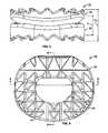
- FIG. 4is an inferior view of the intervertebral implant of FIG. 2 .
- FIG. 5is a sectional view taken along the line 5-5 of FIG. 4 .
- FIG. 6is a sectional view taken along the line 6-6 of FIG. 4 .
- an exemplary intervertebral implant 10is illustrated as positioned or implanted between two adjacent vertebral bodies 12 of a spine.
- the intervertebral implant 10can be positioned between endplates 14 of the vertebral bodies 12 to replace a degenerative disc.
- the intervertebral implant 10can be positioned between adjacent vertebral bodies 12 in a cervical region of the spine, however, the intervertebral implant 10 can be used in other anatomical locations, such as the lumbar or thoracic spine.
- intervertebral implant 10is illustrated and described herein as being positioned between a single pair of adjacent vertebral bodies 12 , it should be understood that any number of intervertebral implants 10 could be positioned between any suitable pair of vertebral bodies 12 .
- the intervertebral implant 10can be shaped such that the intervertebral implant 10 provides mutually articulating motion at a reduced implant height, which can allow for more natural motion of a spine of a patient.
- the intervertebral implant 10can include multiple components configured for mutual articulation to enable anatomical motion between two adjacent vertebral bodies 12 .
- the intervertebral implant 10can include a first or inferior component 18 and a second or superior component 20 .
- the inferior component 18 and the superior component 20can be positioned between adjacent vertebral bodies 12 , and can be sized to re-establish a disc height H D associated with a healthy disc 16 to its original dimension.
- At least one of the first and second components 18 , 20can have a generally toroidal shape.
- the phrase “generally toroidal shape” and “generally toroid”shall mean a shape having a main body 22 defining a substantially closed perimeter and an opening or aperture 24 .
- the aperture 24can be a generally central opening, insofar as it is surrounded by the main body 22 .
- the superior component 20can have the generally toroidal shape. In other applications, however, the inferior component 18 can additionally or alternatively have the generally toroidal shape.
- the inferior component 18can comprise an integral component, which can be composed of a suitable biocompatible material, such as a biocompatible metal or polymer.
- the inferior component 18can be composed of titanium, cobalt chromium, stainless steel, pyrolytic carbon, etc.
- the inferior component 18can be coated with a suitable biocompatible coating, such as an antibiotic, bone growth material, etc.
- a suitable biocompatible coatingsuch as an antibiotic, bone growth material, etc.
- the inferior component 18is described and illustrated herein as comprising a single integral component, the inferior component 18 could comprise multiple components coupled together, if desired.
- the inferior component 18could comprise a biocompatible polymer, such as polyethylene, coupled to a biocompatible metal, such as titanium, through a suitable technique.
- the inferior component 18can include a first articulating surface 26 and a first bone engagement surface 28 .
- the first articulating surface 26can be positioned opposite the first bone engagement surface 28 .
- the first articulating surface 26can cooperate with the superior component 20 to enable relative motion between the inferior component 18 and the superior component 20 .
- the first articulating surface 26can be convex, concave or combinations thereof. In the example of FIGS. 2-6 , the first articulating surface 26 can be generally convex. In this regard, as best shown in FIG. 5 , the first articulating surface 26 can be substantially hemispherical, and can include a first radius of curvature. It should be noted, however, that the first articulating surface 26 can have any shape that enables motion between the inferior component 18 and the superior component 20 . For example, the first articulating surface 26 can include distinct radii of curvature that may or may not be concentric.
- the first bone engagement surface 28can engage a first vertebra or vertebral body 12 a .
- the first bone engagement surface 28may be configured in any manner well known in the art to resist expulsion of the intervertebral implant 10 from between the adjacent vertebral bodies 12 , and to enable the inferior component 18 to self-center or self-align relative to the vertebral body 12 a .
- the first bone engagement surface 28can include aggressive multi-angled and self-centering teeth 29 for fixation. The particular structure of the first bone engagement surface 28 will be understood to be beyond the scope of the present teachings.
- the teeth 29 of the first bone engagement surface 28can each include an elongate angled surface T 1 , which can terminate at a distal point.
- the distal pointcan bite into or alter the surface of the vertebral body 12 a to couple or fix the inferior component 18 to the vertebral body 12 a ( FIG. 1 ).
- the various elongate angled surfaces T 1 of the teeth 29can be arranged so as to enable the inferior component 18 to self-center under loads from the adjacent vertebral bodies 12 .
- the elongate angled surfaces T 1 of a first sub-plurality 29 a of the teeth 29can extend in a first direction D 1
- a second sub-plurality 29 b of the teeth 29can extend in a second direction D 2
- a third sub-plurality 29 c of the teeth 29can extend in a third direction D 3 .
- Each of the first direction D 1 , second direction D 2 and third direction D 3can be substantially different and can each be directed away from an end 18 a of the inferior component 18 .
- the substantially distinct directions of the sub-pluralities 29 a , 29 b , 29 c of the teeth 29can enable the inferior component 18 to self-center or self-align with the vertebral body 12 a .
- the inferior component 18can include a fourth sub-plurality 29 d of teeth 29 , which can prevent the expulsion of the inferior component 18 .
- the superior component 20can comprise an integral component, which can be composed of a suitable biocompatible material, such as a biocompatible metal or polymer.
- the superior component 20can be composed of titanium, cobalt chromium, stainless steel, pyrolytic carbon, etc.
- the superior component 20can be coated with a suitable biocompatible coating, such as an antibiotic, bone growth material, etc.
- the superior component 20can be composed of the same material as the inferior component 18 , or can be composed of a different material than the inferior component 18 , depending upon desired strength properties, wear properties, etc. It should be noted that although the superior component 20 is described and illustrated herein as comprising a single integral component, the superior component 20 could comprise multiple components coupled together, if desired.
- the superior component 20could comprise a biocompatible polymer, such as polyethylene, coupled to a biocompatible metal, such as titanium, through a suitable technique.
- the superior component 20can be generally toroidal in shape, and can include a second articulating surface 30 , a second bone engagement surface 32 and the aperture 24 .
- the second articulating surface 30may be of any shape to cooperate with the first articulating surface 26 to enable relative motion between the inferior component 18 and the superior component 20 .
- the second articulating surface 30can comprise any surface that can cooperate with the first articulating surface 26 to enable relative motion between the vertebral bodies 12 .
- the first articulating surface 26can have a generally convex shape
- the second articulating surface 30can have a generally concave shape.
- the first articulating surface 26could comprise a generally concave shape
- the second articulating surface 30could comprise a generally convex shape, if desired.
- the second articulating surface 30can have a generally hemispherical surface, which can define a second radius of curvature. It should be noted, however, that the second articulating surface 30 can have any shape that enables motion between the inferior component 18 and the superior component 20 .
- the second articulating surface 30could comprise distinct radii of curvature that may or may not be concentric.
- the second radius of curvaturecan be greater than the first radius of curvature, which can establish line contact between the first articulating surface 26 and the second articulating surface 30 of the inferior component 18 and the superior component 20 .
- the line contactmay be generally arcuate due to the generally hemispherical surfaces of each of the inferior component 18 and the superior component 20 .
- the line contact between the inferior component 18 and the superior component 20can maintain stable articulation between the inferior component 18 and the superior component 20 .
- the intervertebral implant 10can be devoid of any positive coupling between the inferior component 18 and the superior component 20 while the inferior component 18 and the superior component 20 are in contact with each other along the line of contact.
- the profile of the intervertebral implant 10may be reduced without compromising the performance of the intervertebral implant 10 .
- the second bone engagement surface 32can engage a second vertebra or vertebral body 12 b .
- the second bone engagement surface 32may be configured in any manner well known in the art to resist expulsion of the intervertebral implant 10 from between the adjacent vertebral bodies 12 , and to enable the superior component 20 to self-center or self-align relative to the vertebral body 12 b .
- the second bone engagement surface 32can be similar to the first bone engagement surface 28 described with regard to the inferior component 18 , the second bone engagement surface 32 will not be discussed in great detail herein, and the same reference numerals will be used to denote the same or similar components.
- the second bone engagement surface 32can include the teeth 29 , which can self-center or self-align the superior component 20 relative to the vertebral body 12 b , while resisting the expulsion of the superior component 20 .
- the second bone engagement surface 32can include any suitable bone engagement surface known in the art, such as spikes, barbs, etc.
- the aperture 24can be formed through the superior component 20 so as to extend from the second articulating surface 30 to the second bone engagement surface 32 .
- the aperture 24can generally receive a portion of the first articulating surface 26 of the inferior component 18 , which can reduce an implant height H of the intervertebral implant 10 , as will be discussed in greater detail herein ( FIG. 3 ). It will be understood, however, that the aperture 24 need not extend through the superior component 20 .
- the opening 24can extend through only a portion of the superior component 20 . In the case of the opening 24 extending only partially through the superior component 20 , the opening 24 may intersect the second articulating surface 30 , but may extend only substantially through the superior component 20 .
- the aperture 24can be formed as a depression within the second articulating surface 30 so that the aperture 24 can receive the first articulating surface 26 of the inferior component 18 to reduce the height H of the intervertebral implant 10 , but the aperture 24 need not extend all the way through the superior component 20 .
- At least one of the inferior component 18 and the superior component 20can comprise a shell 34 and an inner core 36 .
- the inferior component 18 and/or superior component 20can have increased wear properties while providing a degree of compressibility.
- the use of a shell 34 and an inner core 36can provide the benefits of two materials through a single integral component.
- the shell 34can be constructed of a first material having a first hardness.
- the shell 34can form an outer surface S of the inferior component 18 and/or the superior component 20
- the shell 34can have a suitable hardness that enables the inferior component 18 and/or the superior component 20 to engage the vertebral bodies 12 and articulate relative to each other.
- the shell 34can have a thickness T.
- the thickness T of the shell 34can coordinate with the hardness of the shell 34 to facilitate the desired wear characteristics and to enable a degree of compressibility for the inferior component 18 and/or the superior component 20 . It can be desirable to have a degree of compressibility for the inferior component 18 and/or the superior component 20 as it enables the patient to undergo some flexion of the spine, thereby providing the patient with more natural motion.
- the inner core 36can be constructed of a second material having a second hardness. As the inner core 36 can be wholly retained within the shell 34 , the second hardness of the inner core 36 can be distinct from the first hardness of the shell 34 . In this example, the first hardness of the shell 34 can be greater than the second hardness of the inner core 36 .
- the shell 34can be constructed of pyrolytic carbon and the inner core 36 can be constructed of graphite. The use of the pyrolytic carbon for the shell 34 can protect the inferior component 18 and/or the superior component 20 from wear, while the use of graphite for the inner core 36 can provide a degree of compressibility for the inferior component 18 and/or the superior component 20 .
- each of the inferior component 18 and the superior component 20can include the shell 34 and the inner core 36 , however, it will be understood that only one of the inferior component 18 or the superior component 20 or none of the inferior component 18 and the superior component 20 could include the shell 34 and inner core 36 .
- the inferior component 18can be aligned with the superior component 20 such that the first articulating surface 26 is at least partially received within the aperture 24 , and the first articulating surface 26 is in contact with the second articulating surface 30 . Then, with the intervertebral implant 10 assembled, the intervertebral implant 10 can be inserted into the anatomy.
- the insertion of the intervertebral implant 10is generally well known in the art, the insertion of the intervertebral implant 10 will not be discussed in great detail herein. Briefly, however, in order to insert the intervertebral implant 10 into the anatomy, such as between adjacent vertebral bodies 12 ( FIG.
- the anatomycan be prepared to receive in the intervertebral implant 10 .
- surgical accesscan be made to an area adjacent to the vertebral bodies 12 .
- surgical accesscan be obtained via a minimally invasive surgical procedure or a posterior unilateral open procedure.
- the surgical sitecan be prepared to receive the intervertebral implant 10 .
- the intervertebral implant 10can be coupled to a suitable instrument, which can guide the intervertebral implant 10 into the space defined between the adjacent vertebral bodies 12 .
- the intervertebral implant 10can restore the space between the adjacent vertebral bodies 12 to a height substantially similar to the height H D of a healthy disc 16 .
- the implant height H of the intervertebral implant 10can be substantially similar to the height H D of a healthy disc 16 so as to restore substantially normal function to the spine of the patient.
- the implant height H D of the intervertebral implant 10can range from about 4.0 millimeters (mm) to about 9.0 millimeters (mm).
- the implanted height H of the intervertebral implant 10may be no greater than 8.5 millimeters (mm).
- the implanted height H of the intervertebral implant 10may be different than a height H F associated with an assembled intervertebral implant 10 , as the teeth 29 of the first bone engagement surface 28 and the second bone engagement surface 32 may bite into and be substantially received into the respective vertebral body 12 .
- the implant height H of the intervertebral implant 10can be adjusted for optimal fit between the adjacent vertebral bodies 12 , and the implant height H can depend upon the particular anatomical conditions of the patient.
- it may be desirable to provide a kit of various intervertebral implants 10each having a distinct implant height H.
Landscapes
- Health & Medical Sciences (AREA)
- Engineering & Computer Science (AREA)
- Biomedical Technology (AREA)
- Neurology (AREA)
- Orthopedic Medicine & Surgery (AREA)
- Cardiology (AREA)
- Oral & Maxillofacial Surgery (AREA)
- Transplantation (AREA)
- Heart & Thoracic Surgery (AREA)
- Vascular Medicine (AREA)
- Life Sciences & Earth Sciences (AREA)
- Animal Behavior & Ethology (AREA)
- General Health & Medical Sciences (AREA)
- Public Health (AREA)
- Veterinary Medicine (AREA)
- Prostheses (AREA)
Abstract
Description
Claims (30)
Priority Applications (4)
| Application Number | Priority Date | Filing Date | Title |
|---|---|---|---|
| EP10806828.9AEP2461771A4 (en) | 2009-08-07 | 2010-07-20 | Toroid-shaped spinal disc |
| PCT/US2010/042542WO2011016989A2 (en) | 2009-08-07 | 2010-07-20 | Toroid-shaped spinal disc |
| US12/839,491US9173748B2 (en) | 2009-08-07 | 2010-07-20 | Toroid-shaped spinal disc |
| US12/840,623US20110035010A1 (en) | 2009-08-07 | 2010-07-21 | Toroid-shaped spinal disc |
Applications Claiming Priority (2)
| Application Number | Priority Date | Filing Date | Title |
|---|---|---|---|
| US23220809P | 2009-08-07 | 2009-08-07 | |
| US12/839,491US9173748B2 (en) | 2009-08-07 | 2010-07-20 | Toroid-shaped spinal disc |
Related Child Applications (1)
| Application Number | Title | Priority Date | Filing Date |
|---|---|---|---|
| US12/840,623Continuation-In-PartUS20110035010A1 (en) | 2009-08-07 | 2010-07-21 | Toroid-shaped spinal disc |
Publications (2)
| Publication Number | Publication Date |
|---|---|
| US20110035006A1 US20110035006A1 (en) | 2011-02-10 |
| US9173748B2true US9173748B2 (en) | 2015-11-03 |
Family
ID=43535410
Family Applications (1)
| Application Number | Title | Priority Date | Filing Date |
|---|---|---|---|
| US12/839,491Active2031-12-29US9173748B2 (en) | 2009-08-07 | 2010-07-20 | Toroid-shaped spinal disc |
Country Status (3)
| Country | Link |
|---|---|
| US (1) | US9173748B2 (en) |
| EP (1) | EP2461771A4 (en) |
| WO (1) | WO2011016989A2 (en) |
Cited By (4)
| Publication number | Priority date | Publication date | Assignee | Title |
|---|---|---|---|---|
| US20160051371A1 (en)* | 2014-08-19 | 2016-02-25 | Scott DeFelice | Spinal implant and method for fabricating the same |
| EP3597154A1 (en) | 2018-07-20 | 2020-01-22 | Fellowship Of Orthopaedic Researchers, LLC | Magnetic intervertebral disc replacement devices |
| US11872138B2 (en) | 2005-09-23 | 2024-01-16 | Ldr Medical | Intervertebral disc prosthesis |
| US11957598B2 (en) | 2004-02-04 | 2024-04-16 | Ldr Medical | Intervertebral disc prosthesis |
Families Citing this family (4)
| Publication number | Priority date | Publication date | Assignee | Title |
|---|---|---|---|---|
| US9173748B2 (en)* | 2009-08-07 | 2015-11-03 | Ebi, Llc | Toroid-shaped spinal disc |
| US20110035010A1 (en)* | 2009-08-07 | 2011-02-10 | Ebi, Llc | Toroid-shaped spinal disc |
| US8858636B2 (en)* | 2010-04-09 | 2014-10-14 | DePuy Synthes Products, LLC | Intervertebral implant |
| US9408711B2 (en) | 2013-03-14 | 2016-08-09 | Brian D. Burkinshaw | Unitary spinal disc implant |
Citations (95)
| Publication number | Priority date | Publication date | Assignee | Title |
|---|---|---|---|---|
| US4759766A (en)* | 1984-09-04 | 1988-07-26 | Humboldt-Universitaet Zu Berlin | Intervertebral disc endoprosthesis |
| US5284676A (en) | 1990-08-17 | 1994-02-08 | Carbon Implants, Inc. | Pyrolytic deposition in a fluidized bed |
| US5401269A (en)* | 1992-03-13 | 1995-03-28 | Waldemar Link Gmbh & Co. | Intervertebral disc endoprosthesis |
| US5507816A (en)* | 1991-12-04 | 1996-04-16 | Customflex Limited | Spinal vertebrae implants |
| US5514410A (en) | 1994-09-08 | 1996-05-07 | Carbon Implants, Inc. | Pyrocarbon and process for depositing pyrocarbon coatings |
| US5782832A (en)* | 1996-10-01 | 1998-07-21 | Surgical Dynamics, Inc. | Spinal fusion implant and method of insertion thereof |
| US5895428A (en)* | 1996-11-01 | 1999-04-20 | Berry; Don | Load bearing spinal joint implant |
| US5899939A (en) | 1998-01-21 | 1999-05-04 | Osteotech, Inc. | Bone-derived implant for load-supporting applications |
| US5899941A (en)* | 1997-12-09 | 1999-05-04 | Chubu Bearing Kabushiki Kaisha | Artificial intervertebral disk |
| US6113637A (en) | 1998-10-22 | 2000-09-05 | Sofamor Danek Holdings, Inc. | Artificial intervertebral joint permitting translational and rotational motion |
| FR2799116A1 (en) | 1999-09-30 | 2001-04-06 | Euros Sa | Intervertebral implant comprises pure or alloyed pyrocarbon and is placed between two vertebrae and interacts by means of friction with at least one of them |
| US6261322B1 (en) | 1998-05-14 | 2001-07-17 | Hayes Medical, Inc. | Implant with composite coating |
| US6294187B1 (en) | 1999-02-23 | 2001-09-25 | Osteotech, Inc. | Load-bearing osteoimplant, method for its manufacture and method of repairing bone using same |
| US20020035400A1 (en)* | 2000-08-08 | 2002-03-21 | Vincent Bryan | Implantable joint prosthesis |
| US6410087B1 (en) | 1999-11-01 | 2002-06-25 | Medical Carbon Research Institute, Llc | Deposition of pyrocarbon |
| US20020111685A1 (en)* | 2001-02-15 | 2002-08-15 | Ralph James D. | Intervertebral spacer device utilizing a spirally slotted belleville washer having radially spaced concentric grooves |
| US6436146B1 (en) | 1997-12-10 | 2002-08-20 | Bioprofile | Implant for treating ailments of a joint or a bone |
| US20030074069A1 (en)* | 2001-07-16 | 2003-04-17 | Errico Joseph P. | Artificial intervertebral disc having a captured ball and socket joint with a solid ball and retaining cap |
| US6607558B2 (en) | 2001-07-03 | 2003-08-19 | Axiomed Spine Corporation | Artificial disc |
| US20030191534A1 (en)* | 2000-03-10 | 2003-10-09 | Guy Viart | Intervertebral disc prosthesis |
| US20030199981A1 (en)* | 2002-04-23 | 2003-10-23 | Ferree Bret A. | Artificial disc replacements with natural kinematics |
| US20030220691A1 (en)* | 2002-05-23 | 2003-11-27 | Pioneer Laboratories, Inc. | Artificial intervertebral disc device |
| US20030233146A1 (en)* | 2002-06-18 | 2003-12-18 | Alexander Grinberg | Intervertebral disc |
| US20040002762A1 (en)* | 2002-06-27 | 2004-01-01 | Hawkins John Riley | Prosthetic intervertebral motion disc having dampening |
| US6696073B2 (en) | 1999-02-23 | 2004-02-24 | Osteotech, Inc. | Shaped load-bearing osteoimplant and methods of making same |
| US20040044410A1 (en)* | 2002-05-10 | 2004-03-04 | Ferree Bret A. | Prosthetic components with contained compressible resilient members |
| US20040054411A1 (en) | 2000-08-08 | 2004-03-18 | Sdgi Holdings, Inc. | Wear-resistant endoprosthetic devices |
| US20040068320A1 (en) | 2002-10-04 | 2004-04-08 | Robie Bruce H. | Prosthetic disc and vertebral body replacement device having pyrolytic carbon bearing members |
| US20040143334A1 (en) | 2003-01-08 | 2004-07-22 | Ferree Bret A. | Artificial disc replacements (ADRS) with features to enhance longevity and prevent extrusion |
| US20050021146A1 (en)* | 2003-05-27 | 2005-01-27 | Spinalmotion, Inc. | Intervertebral prosthetic disc |
| US20050027364A1 (en) | 2003-08-01 | 2005-02-03 | Kim Daniel H. | Prosthetic intervertebral disc and methods for using the same |
| US20050060034A1 (en) | 2003-09-15 | 2005-03-17 | Sdgi Holdings, Inc. | Revisable prosthetic device |
| US20050143824A1 (en) | 2003-05-06 | 2005-06-30 | Marc Richelsoph | Artificial intervertebral disc |
| US20050165485A1 (en)* | 2004-01-27 | 2005-07-28 | Sdgi Holdings, Inc. | Hybrid intervertebral disc system |
| US20050197706A1 (en) | 2004-02-04 | 2005-09-08 | Ldr Medical, Inc. | Intervertebral disc prosthesis |
| US20050246022A1 (en)* | 2004-02-20 | 2005-11-03 | Rafail Zubok | Artificial intervertebral disc having a universal joint |
| US20050246032A1 (en) | 2002-06-21 | 2005-11-03 | Medical Carbon Research Institute | Bone and tissue implants and method of making |
| US20050251260A1 (en) | 2002-08-15 | 2005-11-10 | David Gerber | Controlled artificial intervertebral disc implant |
| US6969405B2 (en)* | 2003-04-23 | 2005-11-29 | Loubert Suddaby | Inflatable intervertebral disc replacement prosthesis |
| US20050273171A1 (en) | 2003-08-05 | 2005-12-08 | Gordon Charles R | Method of inserting an expandable intervertebral implant without overdistraction |
| US20060085076A1 (en)* | 2004-10-15 | 2006-04-20 | Manoj Krishna | Posterior spinal arthroplasty-development of a new posteriorly inserted artificial disc and an artificial facet joint |
| US20060149372A1 (en) | 2004-12-17 | 2006-07-06 | Paxson Robert D | Artificial spinal disc |
| US20060149371A1 (en) | 2004-12-10 | 2006-07-06 | Sdgi Holdings, Inc. | Intervertebral prosthetic device and method with locking mechanism |
| US7083651B2 (en)* | 2004-03-03 | 2006-08-01 | Joint Synergy, Llc | Spinal implant |
| US20060190079A1 (en)* | 2005-01-21 | 2006-08-24 | Naim Istephanous | Articulating spinal disc implants with amorphous metal elements |
| US20060212122A1 (en)* | 2003-07-12 | 2006-09-21 | Fiorella Perera | Intervertebral disk prosthesis |
| US20060235527A1 (en) | 2004-10-18 | 2006-10-19 | Karin Buettner-Janz | Intervertebral disc prosthesis with a motion- adapted edge for the lumbar and cervical spine |
| US20060241772A1 (en)* | 2004-10-18 | 2006-10-26 | Karin Buettner-Janz | Physiologically movable intervertebral disc prosthesis for the lumbar and cervical spine |
| US7128761B2 (en) | 2003-12-10 | 2006-10-31 | Axiomed Spine Corporation | Method and apparatus for replacing a damaged spinal disc |
| US20060265068A1 (en)* | 2005-05-17 | 2006-11-23 | Schwab Frank J | Intervertebral implant |
| US20060287728A1 (en) | 2005-06-21 | 2006-12-21 | Mokhtar Mourad B | System and method for implanting intervertebral disk prostheses |
| US7166131B2 (en) | 2002-10-28 | 2007-01-23 | Synthes (Usa) | Intervertebral disk prosthesis or artificial vertebra |
| US7169181B2 (en) | 2002-12-10 | 2007-01-30 | Axiomed Spine Corporation | Artificial disc |
| US7195644B2 (en)* | 2004-03-02 | 2007-03-27 | Joint Synergy, Llc | Ball and dual socket joint |
| US20070100456A1 (en) | 2005-10-31 | 2007-05-03 | Depuy Spine, Inc. | Intervertebral disc prosthesis with shear-limiting core |
| US20070118219A1 (en)* | 2004-03-25 | 2007-05-24 | Hyde Edward R Jr | Transosseous spine core approach method implant and instrumentation |
| US7238205B2 (en) | 2004-01-15 | 2007-07-03 | Warsaw Orthopedic, Inc. | Universal interference cleat |
| US20070156250A1 (en) | 2005-12-09 | 2007-07-05 | Seitz William H Jr | Orthopedic Implants Coated with Pyrolytic Carbon |
| US20070154514A1 (en) | 2005-12-30 | 2007-07-05 | Demakas John J | Therapeutic Structures |
| US20070168037A1 (en)* | 2006-01-13 | 2007-07-19 | Posnick Jeffrey C | Orthopedic implant |
| US20070173941A1 (en) | 2006-01-25 | 2007-07-26 | Sdgi Holdings, Inc. | Intervertebral prosthetic disc and method of installing same |
| US20070179615A1 (en) | 2006-01-31 | 2007-08-02 | Sdgi Holdings, Inc. | Intervertebral prosthetic disc |
| US20070225822A1 (en) | 2005-12-09 | 2007-09-27 | Santilli Albert N | Orthopedic Implants Coated with Pyrolytic Carbon |
| US20070233246A1 (en)* | 2006-03-31 | 2007-10-04 | Sdgi Holdings, Inc. | Spinal implants with improved mechanical response |
| US20070270971A1 (en) | 2006-03-14 | 2007-11-22 | Sdgi Holdings, Inc. | Intervertebral prosthetic disc with improved wear resistance |
| US20070288094A1 (en)* | 2006-06-08 | 2007-12-13 | Manoj Krishna | System and method for lumbar arthroplasty |
| US20080082173A1 (en) | 2006-09-13 | 2008-04-03 | Delurio Robert J | Allograft intervertebral implant and method of manufacturing the same |
| US20080103597A1 (en) | 2004-12-28 | 2008-05-01 | Beat Lechmann | Intervertebral Prosthesis |
| US7393361B2 (en) | 2004-02-20 | 2008-07-01 | Spinecore, Inc. | Artificial intervertebral disc having a bored semispherical bearing with a compression locking post and retaining caps |
| US20080183296A1 (en)* | 2002-04-19 | 2008-07-31 | Ferree Bret A | Mobile bearing artificial disc replacement |
| US20080195212A1 (en)* | 2007-02-09 | 2008-08-14 | Bao-Khang Ngoc Nguyen | Multi-lobe artificial spine joint |
| US20090005872A1 (en)* | 2007-06-26 | 2009-01-01 | Missoum Moumene | Intervertebral Motion Disc With Helical Shock Absorber |
| US20090012619A1 (en)* | 2007-07-03 | 2009-01-08 | Seaspine, Inc. | Motion restoring intervertebral prosthesis with limited angular displacement |
| US20090054986A1 (en)* | 2005-05-02 | 2009-02-26 | Cordaro Nicholas M | Motion restoring intervertebral device |
| US20090049960A1 (en) | 2005-04-09 | 2009-02-26 | Andreas Heinsohn | Pliers |
| US20090088856A1 (en) | 2006-03-14 | 2009-04-02 | Spineart Sa | Intervertebral disk prostheses |
| US7582115B2 (en) | 2004-09-30 | 2009-09-01 | Helmut Weber | Intervertebral prosthesis |
| US20090234458A1 (en) | 2008-03-11 | 2009-09-17 | Spinalmotion, Inc. | Artificial Intervertebral Disc With Lower Height |
| US20090270986A1 (en) | 2005-12-08 | 2009-10-29 | Fbcdevice Aps | Disc Implant |
| US20090276051A1 (en) | 2008-05-05 | 2009-11-05 | Spinalmotion, Inc. | Polyaryletherketone Artificial Intervertebral Disc |
| US7618459B2 (en) | 2005-09-26 | 2009-11-17 | Infinity Orthopedics Ltd. | Universal spinal disc implant system |
| US7628815B2 (en) | 2003-04-11 | 2009-12-08 | Synthes Usa, Llc | Intervertebral implant with moveable endcaps |
| US20100004746A1 (en)* | 2008-07-02 | 2010-01-07 | Spinalmotion, Inc. | Limited Motion Prosthetic Intervertebral Disc |
| RU2379005C2 (en) | 2007-12-25 | 2010-01-20 | Валерий Федорович Татаринов | Intervertebral movable implant from isotropic pyrolytic carbon |
| US20100030338A1 (en) | 2006-12-13 | 2010-02-04 | Spineway | Prosthesis for nucleus or inter-vertebral disc replacement |
| US20100256758A1 (en) | 2009-04-02 | 2010-10-07 | Synvasive Technology, Inc. | Monolithic orthopedic implant with an articular finished surface |
| US20100268337A1 (en) | 2009-04-02 | 2010-10-21 | Synvasive Technology, Inc. | Monolithic orthopedic implant with an articular finished surface |
| US7837739B2 (en) | 2003-04-18 | 2010-11-23 | Ascension Orthopedics, Inc. | Interpositional biarticular disk implant |
| US20100298938A1 (en) | 2004-01-09 | 2010-11-25 | Warsaw Orthopedic, Inc. | Spinal Device and Method |
| US20110035006A1 (en)* | 2009-08-07 | 2011-02-10 | Ebi, Llc | Toroid-Shaped Spinal Disc |
| US20110035010A1 (en) | 2009-08-07 | 2011-02-10 | Ebi, Llc | Toroid-shaped spinal disc |
| US20110082556A1 (en)* | 2004-06-30 | 2011-04-07 | Synergy Disc Replacement, Inc. | Artificial Spinal Disc |
| US20110190888A1 (en) | 2010-02-01 | 2011-08-04 | Bertele Theodore P | Composite Interbody Device And Method of Manufacture |
| US20120172988A1 (en)* | 2011-01-04 | 2012-07-05 | Synthes Usa, Llc | Intervertebral implant with multiple radii |
| US8268002B2 (en) | 2010-01-27 | 2012-09-18 | Warsaw Orthopedic, Inc. | Slide-on end cap for a vertebral implant |
Family Cites Families (1)
| Publication number | Priority date | Publication date | Assignee | Title |
|---|---|---|---|---|
| DE10323363A1 (en)* | 2003-05-21 | 2004-12-09 | Ulrich Gmbh & Co. Kg | Implant for insertion between elements of the vertebral column comprises a hinge which consist of a socket plate and a head element, and is located between the hinge cover plates |
- 2010
- 2010-07-20USUS12/839,491patent/US9173748B2/enactiveActive
- 2010-07-20WOPCT/US2010/042542patent/WO2011016989A2/enactiveApplication Filing
- 2010-07-20EPEP10806828.9Apatent/EP2461771A4/ennot_activeWithdrawn
Patent Citations (115)
| Publication number | Priority date | Publication date | Assignee | Title |
|---|---|---|---|---|
| US4759766A (en)* | 1984-09-04 | 1988-07-26 | Humboldt-Universitaet Zu Berlin | Intervertebral disc endoprosthesis |
| US5284676A (en) | 1990-08-17 | 1994-02-08 | Carbon Implants, Inc. | Pyrolytic deposition in a fluidized bed |
| US5507816A (en)* | 1991-12-04 | 1996-04-16 | Customflex Limited | Spinal vertebrae implants |
| US5401269A (en)* | 1992-03-13 | 1995-03-28 | Waldemar Link Gmbh & Co. | Intervertebral disc endoprosthesis |
| US5514410A (en) | 1994-09-08 | 1996-05-07 | Carbon Implants, Inc. | Pyrocarbon and process for depositing pyrocarbon coatings |
| US5677061A (en) | 1994-09-08 | 1997-10-14 | Medtronic Carbon Implants, Inc. | Pyrocarbon and process for depositing pyrocarbon coatings |
| US5782832A (en)* | 1996-10-01 | 1998-07-21 | Surgical Dynamics, Inc. | Spinal fusion implant and method of insertion thereof |
| US5895428A (en)* | 1996-11-01 | 1999-04-20 | Berry; Don | Load bearing spinal joint implant |
| US5899941A (en)* | 1997-12-09 | 1999-05-04 | Chubu Bearing Kabushiki Kaisha | Artificial intervertebral disk |
| US6436146B1 (en) | 1997-12-10 | 2002-08-20 | Bioprofile | Implant for treating ailments of a joint or a bone |
| US5899939A (en) | 1998-01-21 | 1999-05-04 | Osteotech, Inc. | Bone-derived implant for load-supporting applications |
| US7105030B2 (en) | 1998-05-14 | 2006-09-12 | Hayes Medical, Inc. | Implant with composite coating |
| US7445640B2 (en) | 1998-05-14 | 2008-11-04 | Hayes Medical, Inc. | Implant with composite coating |
| US6261322B1 (en) | 1998-05-14 | 2001-07-17 | Hayes Medical, Inc. | Implant with composite coating |
| US20090254191A1 (en) | 1998-05-14 | 2009-10-08 | Despres Iii Alfred S | Implant with composite coating |
| US6113637A (en) | 1998-10-22 | 2000-09-05 | Sofamor Danek Holdings, Inc. | Artificial intervertebral joint permitting translational and rotational motion |
| US6294187B1 (en) | 1999-02-23 | 2001-09-25 | Osteotech, Inc. | Load-bearing osteoimplant, method for its manufacture and method of repairing bone using same |
| US6696073B2 (en) | 1999-02-23 | 2004-02-24 | Osteotech, Inc. | Shaped load-bearing osteoimplant and methods of making same |
| FR2799116A1 (en) | 1999-09-30 | 2001-04-06 | Euros Sa | Intervertebral implant comprises pure or alloyed pyrocarbon and is placed between two vertebrae and interacts by means of friction with at least one of them |
| US6410087B1 (en) | 1999-11-01 | 2002-06-25 | Medical Carbon Research Institute, Llc | Deposition of pyrocarbon |
| US20030191534A1 (en)* | 2000-03-10 | 2003-10-09 | Guy Viart | Intervertebral disc prosthesis |
| US20040054411A1 (en) | 2000-08-08 | 2004-03-18 | Sdgi Holdings, Inc. | Wear-resistant endoprosthetic devices |
| US7601174B2 (en) | 2000-08-08 | 2009-10-13 | Warsaw Orthopedic, Inc. | Wear-resistant endoprosthetic devices |
| US20020035400A1 (en)* | 2000-08-08 | 2002-03-21 | Vincent Bryan | Implantable joint prosthesis |
| US20020111685A1 (en)* | 2001-02-15 | 2002-08-15 | Ralph James D. | Intervertebral spacer device utilizing a spirally slotted belleville washer having radially spaced concentric grooves |
| US6607558B2 (en) | 2001-07-03 | 2003-08-19 | Axiomed Spine Corporation | Artificial disc |
| US20030074069A1 (en)* | 2001-07-16 | 2003-04-17 | Errico Joseph P. | Artificial intervertebral disc having a captured ball and socket joint with a solid ball and retaining cap |
| US20080183296A1 (en)* | 2002-04-19 | 2008-07-31 | Ferree Bret A | Mobile bearing artificial disc replacement |
| US20050228497A1 (en)* | 2002-04-23 | 2005-10-13 | Ferree Bret A | Artificial disc replacements with natural kinematics |
| US20030199981A1 (en)* | 2002-04-23 | 2003-10-23 | Ferree Bret A. | Artificial disc replacements with natural kinematics |
| US20040044410A1 (en)* | 2002-05-10 | 2004-03-04 | Ferree Bret A. | Prosthetic components with contained compressible resilient members |
| US20030220691A1 (en)* | 2002-05-23 | 2003-11-27 | Pioneer Laboratories, Inc. | Artificial intervertebral disc device |
| US7001433B2 (en) | 2002-05-23 | 2006-02-21 | Pioneer Laboratories, Inc. | Artificial intervertebral disc device |
| US6770095B2 (en) | 2002-06-18 | 2004-08-03 | Depuy Acroned, Inc. | Intervertebral disc |
| US20030233146A1 (en)* | 2002-06-18 | 2003-12-18 | Alexander Grinberg | Intervertebral disc |
| US20050246032A1 (en) | 2002-06-21 | 2005-11-03 | Medical Carbon Research Institute | Bone and tissue implants and method of making |
| US6793678B2 (en) | 2002-06-27 | 2004-09-21 | Depuy Acromed, Inc. | Prosthetic intervertebral motion disc having dampening |
| US20040002762A1 (en)* | 2002-06-27 | 2004-01-01 | Hawkins John Riley | Prosthetic intervertebral motion disc having dampening |
| US20050251260A1 (en) | 2002-08-15 | 2005-11-10 | David Gerber | Controlled artificial intervertebral disc implant |
| US20040068320A1 (en) | 2002-10-04 | 2004-04-08 | Robie Bruce H. | Prosthetic disc and vertebral body replacement device having pyrolytic carbon bearing members |
| US7749272B2 (en) | 2002-10-04 | 2010-07-06 | Zimmer Trabecular Metal Technology, Inc. | Prosthetic disc and vertebral body replacement device having pyrolytic carbon bearing members |
| US7166131B2 (en) | 2002-10-28 | 2007-01-23 | Synthes (Usa) | Intervertebral disk prosthesis or artificial vertebra |
| US7169181B2 (en) | 2002-12-10 | 2007-01-30 | Axiomed Spine Corporation | Artificial disc |
| US20040143334A1 (en) | 2003-01-08 | 2004-07-22 | Ferree Bret A. | Artificial disc replacements (ADRS) with features to enhance longevity and prevent extrusion |
| US7628815B2 (en) | 2003-04-11 | 2009-12-08 | Synthes Usa, Llc | Intervertebral implant with moveable endcaps |
| US7837739B2 (en) | 2003-04-18 | 2010-11-23 | Ascension Orthopedics, Inc. | Interpositional biarticular disk implant |
| US6969405B2 (en)* | 2003-04-23 | 2005-11-29 | Loubert Suddaby | Inflatable intervertebral disc replacement prosthesis |
| US20050267580A1 (en)* | 2003-04-23 | 2005-12-01 | Loubert Suddaby | Inflatable intervertebral disc replacement prosthesis |
| US20050143824A1 (en) | 2003-05-06 | 2005-06-30 | Marc Richelsoph | Artificial intervertebral disc |
| US20080215155A1 (en)* | 2003-05-27 | 2008-09-04 | Spinalmotion, Inc. | Intervertebral prosthetic disc |
| US20050021146A1 (en)* | 2003-05-27 | 2005-01-27 | Spinalmotion, Inc. | Intervertebral prosthetic disc |
| US20130013069A1 (en)* | 2003-05-27 | 2013-01-10 | Spinalmotion, Inc. | Intervertebral prosthetic disc |
| US20060212122A1 (en)* | 2003-07-12 | 2006-09-21 | Fiorella Perera | Intervertebral disk prosthesis |
| US20050027364A1 (en) | 2003-08-01 | 2005-02-03 | Kim Daniel H. | Prosthetic intervertebral disc and methods for using the same |
| US7153325B2 (en) | 2003-08-01 | 2006-12-26 | Ultra-Kinetics, Inc. | Prosthetic intervertebral disc and methods for using the same |
| US20050273171A1 (en) | 2003-08-05 | 2005-12-08 | Gordon Charles R | Method of inserting an expandable intervertebral implant without overdistraction |
| US20050060034A1 (en) | 2003-09-15 | 2005-03-17 | Sdgi Holdings, Inc. | Revisable prosthetic device |
| US7588600B2 (en) | 2003-12-10 | 2009-09-15 | Axiomed Spine Corporation | Method for replacing a damaged spinal disc |
| US7128761B2 (en) | 2003-12-10 | 2006-10-31 | Axiomed Spine Corporation | Method and apparatus for replacing a damaged spinal disc |
| US7695517B2 (en) | 2003-12-10 | 2010-04-13 | Axiomed Spine Corporation | Apparatus for replacing a damaged spinal disc |
| US20100298938A1 (en) | 2004-01-09 | 2010-11-25 | Warsaw Orthopedic, Inc. | Spinal Device and Method |
| US7238205B2 (en) | 2004-01-15 | 2007-07-03 | Warsaw Orthopedic, Inc. | Universal interference cleat |
| US20060259144A1 (en) | 2004-01-27 | 2006-11-16 | Warsaw Orthopedic Inc. | Hybrid intervertebral disc system |
| US20050165485A1 (en)* | 2004-01-27 | 2005-07-28 | Sdgi Holdings, Inc. | Hybrid intervertebral disc system |
| US20050197706A1 (en) | 2004-02-04 | 2005-09-08 | Ldr Medical, Inc. | Intervertebral disc prosthesis |
| US7393361B2 (en) | 2004-02-20 | 2008-07-01 | Spinecore, Inc. | Artificial intervertebral disc having a bored semispherical bearing with a compression locking post and retaining caps |
| US20050246022A1 (en)* | 2004-02-20 | 2005-11-03 | Rafail Zubok | Artificial intervertebral disc having a universal joint |
| US7195644B2 (en)* | 2004-03-02 | 2007-03-27 | Joint Synergy, Llc | Ball and dual socket joint |
| US7083651B2 (en)* | 2004-03-03 | 2006-08-01 | Joint Synergy, Llc | Spinal implant |
| US20070118219A1 (en)* | 2004-03-25 | 2007-05-24 | Hyde Edward R Jr | Transosseous spine core approach method implant and instrumentation |
| US20110082556A1 (en)* | 2004-06-30 | 2011-04-07 | Synergy Disc Replacement, Inc. | Artificial Spinal Disc |
| US7582115B2 (en) | 2004-09-30 | 2009-09-01 | Helmut Weber | Intervertebral prosthesis |
| US20060085076A1 (en)* | 2004-10-15 | 2006-04-20 | Manoj Krishna | Posterior spinal arthroplasty-development of a new posteriorly inserted artificial disc and an artificial facet joint |
| US20100137992A1 (en)* | 2004-10-18 | 2010-06-03 | Buettner-Janz Karin | Physologically Movable Intervertebral Disc Prosthesis for the Lumbar and Cervical Spine |
| US20060235527A1 (en) | 2004-10-18 | 2006-10-19 | Karin Buettner-Janz | Intervertebral disc prosthesis with a motion- adapted edge for the lumbar and cervical spine |
| US20060241772A1 (en)* | 2004-10-18 | 2006-10-26 | Karin Buettner-Janz | Physiologically movable intervertebral disc prosthesis for the lumbar and cervical spine |
| US20060149371A1 (en) | 2004-12-10 | 2006-07-06 | Sdgi Holdings, Inc. | Intervertebral prosthetic device and method with locking mechanism |
| US20060149372A1 (en) | 2004-12-17 | 2006-07-06 | Paxson Robert D | Artificial spinal disc |
| US20080103597A1 (en) | 2004-12-28 | 2008-05-01 | Beat Lechmann | Intervertebral Prosthesis |
| US20060190079A1 (en)* | 2005-01-21 | 2006-08-24 | Naim Istephanous | Articulating spinal disc implants with amorphous metal elements |
| US20090049960A1 (en) | 2005-04-09 | 2009-02-26 | Andreas Heinsohn | Pliers |
| US20090054986A1 (en)* | 2005-05-02 | 2009-02-26 | Cordaro Nicholas M | Motion restoring intervertebral device |
| US20060265068A1 (en)* | 2005-05-17 | 2006-11-23 | Schwab Frank J | Intervertebral implant |
| US20060287728A1 (en) | 2005-06-21 | 2006-12-21 | Mokhtar Mourad B | System and method for implanting intervertebral disk prostheses |
| US7618459B2 (en) | 2005-09-26 | 2009-11-17 | Infinity Orthopedics Ltd. | Universal spinal disc implant system |
| US20070100455A1 (en)* | 2005-10-31 | 2007-05-03 | Depuy Spine, Inc. | Method and apparatus for fixation of intervertebral disc prosthesis |
| US20070100456A1 (en) | 2005-10-31 | 2007-05-03 | Depuy Spine, Inc. | Intervertebral disc prosthesis with shear-limiting core |
| US20090270986A1 (en) | 2005-12-08 | 2009-10-29 | Fbcdevice Aps | Disc Implant |
| US20070225822A1 (en) | 2005-12-09 | 2007-09-27 | Santilli Albert N | Orthopedic Implants Coated with Pyrolytic Carbon |
| US20070156250A1 (en) | 2005-12-09 | 2007-07-05 | Seitz William H Jr | Orthopedic Implants Coated with Pyrolytic Carbon |
| US20070154514A1 (en) | 2005-12-30 | 2007-07-05 | Demakas John J | Therapeutic Structures |
| US20070168037A1 (en)* | 2006-01-13 | 2007-07-19 | Posnick Jeffrey C | Orthopedic implant |
| US20070173941A1 (en) | 2006-01-25 | 2007-07-26 | Sdgi Holdings, Inc. | Intervertebral prosthetic disc and method of installing same |
| US20070179615A1 (en) | 2006-01-31 | 2007-08-02 | Sdgi Holdings, Inc. | Intervertebral prosthetic disc |
| US20090088856A1 (en) | 2006-03-14 | 2009-04-02 | Spineart Sa | Intervertebral disk prostheses |
| US20070270971A1 (en) | 2006-03-14 | 2007-11-22 | Sdgi Holdings, Inc. | Intervertebral prosthetic disc with improved wear resistance |
| US20070233246A1 (en)* | 2006-03-31 | 2007-10-04 | Sdgi Holdings, Inc. | Spinal implants with improved mechanical response |
| US20070288094A1 (en)* | 2006-06-08 | 2007-12-13 | Manoj Krishna | System and method for lumbar arthroplasty |
| US20080082173A1 (en) | 2006-09-13 | 2008-04-03 | Delurio Robert J | Allograft intervertebral implant and method of manufacturing the same |
| US20100030338A1 (en) | 2006-12-13 | 2010-02-04 | Spineway | Prosthesis for nucleus or inter-vertebral disc replacement |
| US20080195212A1 (en)* | 2007-02-09 | 2008-08-14 | Bao-Khang Ngoc Nguyen | Multi-lobe artificial spine joint |
| US20090005872A1 (en)* | 2007-06-26 | 2009-01-01 | Missoum Moumene | Intervertebral Motion Disc With Helical Shock Absorber |
| US20090012619A1 (en)* | 2007-07-03 | 2009-01-08 | Seaspine, Inc. | Motion restoring intervertebral prosthesis with limited angular displacement |
| RU2379005C2 (en) | 2007-12-25 | 2010-01-20 | Валерий Федорович Татаринов | Intervertebral movable implant from isotropic pyrolytic carbon |
| US20090234458A1 (en) | 2008-03-11 | 2009-09-17 | Spinalmotion, Inc. | Artificial Intervertebral Disc With Lower Height |
| US20090276051A1 (en) | 2008-05-05 | 2009-11-05 | Spinalmotion, Inc. | Polyaryletherketone Artificial Intervertebral Disc |
| US20100004746A1 (en)* | 2008-07-02 | 2010-01-07 | Spinalmotion, Inc. | Limited Motion Prosthetic Intervertebral Disc |
| US20100268337A1 (en) | 2009-04-02 | 2010-10-21 | Synvasive Technology, Inc. | Monolithic orthopedic implant with an articular finished surface |
| US20100256758A1 (en) | 2009-04-02 | 2010-10-07 | Synvasive Technology, Inc. | Monolithic orthopedic implant with an articular finished surface |
| US20110035006A1 (en)* | 2009-08-07 | 2011-02-10 | Ebi, Llc | Toroid-Shaped Spinal Disc |
| US20110035010A1 (en) | 2009-08-07 | 2011-02-10 | Ebi, Llc | Toroid-shaped spinal disc |
| US8268002B2 (en) | 2010-01-27 | 2012-09-18 | Warsaw Orthopedic, Inc. | Slide-on end cap for a vertebral implant |
| US20110190888A1 (en) | 2010-02-01 | 2011-08-04 | Bertele Theodore P | Composite Interbody Device And Method of Manufacture |
| US20120172991A1 (en) | 2010-02-01 | 2012-07-05 | Bertele Theodore P | Composite Interbody Device |
| US20120172988A1 (en)* | 2011-01-04 | 2012-07-05 | Synthes Usa, Llc | Intervertebral implant with multiple radii |
Non-Patent Citations (3)
| Title |
|---|
| Final Office Action for U.S. Appl. No. 12/840,623, filed Nov. 19, 2012. |
| International Search Report regarding PCT/US2011/040137 dated May 24, 2012. |
| Non-Final Office Action for U.S. Appl. No. 12/840,623, filed Aug. 2, 2012. |
Cited By (7)
| Publication number | Priority date | Publication date | Assignee | Title |
|---|---|---|---|---|
| US11957598B2 (en) | 2004-02-04 | 2024-04-16 | Ldr Medical | Intervertebral disc prosthesis |
| US11872138B2 (en) | 2005-09-23 | 2024-01-16 | Ldr Medical | Intervertebral disc prosthesis |
| US20160051371A1 (en)* | 2014-08-19 | 2016-02-25 | Scott DeFelice | Spinal implant and method for fabricating the same |
| US10105240B2 (en)* | 2014-08-19 | 2018-10-23 | Oxford Performance Materials, Inc. | Spinal implant and method for fabricating the same |
| US20190015217A1 (en)* | 2014-08-19 | 2019-01-17 | Scott DeFelice | Spinal Implant And Method For Fabricating The Same |
| US10881529B2 (en)* | 2014-08-19 | 2021-01-05 | Oxford Performance Materials, Inc. | Spinal implant and method for fabricating the same |
| EP3597154A1 (en) | 2018-07-20 | 2020-01-22 | Fellowship Of Orthopaedic Researchers, LLC | Magnetic intervertebral disc replacement devices |
Also Published As
| Publication number | Publication date |
|---|---|
| EP2461771A2 (en) | 2012-06-13 |
| EP2461771A4 (en) | 2014-01-29 |
| WO2011016989A2 (en) | 2011-02-10 |
| US20110035006A1 (en) | 2011-02-10 |
| WO2011016989A3 (en) | 2011-05-05 |
Similar Documents
| Publication | Publication Date | Title |
|---|---|---|
| US10105233B2 (en) | Anterior prosthetic spinal disc replacement | |
| US7550010B2 (en) | Spinal arthroplasty device and method | |
| US9173748B2 (en) | Toroid-shaped spinal disc | |
| US8753399B2 (en) | Dynamic interbody device | |
| US7887589B2 (en) | Minimally invasive spinal disc stabilizer and insertion tool | |
| US20110035010A1 (en) | Toroid-shaped spinal disc | |
| US8915964B2 (en) | Flexible dampening intervertebral spacer device | |
| US9060871B2 (en) | Total disc replacement device | |
| US9937051B2 (en) | Artificial disc devices and related methods of use | |
| EP1691730A2 (en) | Semi-constrained and mobile-bearing disc prosthesis | |
| US8016885B2 (en) | Cervical motion preservation device | |
| EP1711140B1 (en) | Spinal arthroplasty device and method | |
| US11642227B2 (en) | Dynamic disc assembly |
Legal Events
| Date | Code | Title | Description |
|---|---|---|---|
| AS | Assignment | Owner name:EBI, LLC, NEW JERSEY Free format text:ASSIGNMENT OF ASSIGNORS INTEREST;ASSIGNORS:COOK, STEPHEN D;HARRINGTON, SCOTT;SIGNING DATES FROM 20100811 TO 20100929;REEL/FRAME:025083/0137 | |
| FEPP | Fee payment procedure | Free format text:PAYER NUMBER DE-ASSIGNED (ORIGINAL EVENT CODE: RMPN); ENTITY STATUS OF PATENT OWNER: LARGE ENTITY Free format text:PAYOR NUMBER ASSIGNED (ORIGINAL EVENT CODE: ASPN); ENTITY STATUS OF PATENT OWNER: LARGE ENTITY | |
| STCF | Information on status: patent grant | Free format text:PATENTED CASE | |
| AS | Assignment | Owner name:ZIMMER BIOMET SPINE, INC., COLORADO Free format text:ASSIGNMENT OF ASSIGNORS INTEREST;ASSIGNOR:EBI, LLC;REEL/FRAME:044712/0790 Effective date:20170621 | |
| MAFP | Maintenance fee payment | Free format text:PAYMENT OF MAINTENANCE FEE, 4TH YEAR, LARGE ENTITY (ORIGINAL EVENT CODE: M1551); ENTITY STATUS OF PATENT OWNER: LARGE ENTITY Year of fee payment:4 | |
| AS | Assignment | Owner name:JPMORGAN CHASE BANK, N.A., AS ADMINISTRATIVE AGENT, NEW YORK Free format text:SECURITY INTEREST;ASSIGNORS:BIOMET 3I, LLC;EBI, LLC;ZIMMER BIOMET SPINE, INC.;AND OTHERS;REEL/FRAME:059293/0213 Effective date:20220228 | |
| MAFP | Maintenance fee payment | Free format text:PAYMENT OF MAINTENANCE FEE, 8TH YEAR, LARGE ENTITY (ORIGINAL EVENT CODE: M1552); ENTITY STATUS OF PATENT OWNER: LARGE ENTITY Year of fee payment:8 | |
| AS | Assignment | Owner name:CERBERUS BUSINESS FINANCE AGENCY, LLC, NEW YORK Free format text:GRANT OF A SECURITY INTEREST -- PATENTS;ASSIGNORS:ZIMMER BIOMET SPINE, LLC;EBI, LLC;REEL/FRAME:066970/0806 Effective date:20240401 | |
| AS | Assignment | Owner name:ZIMMER BIOMET SPINE, LLC (F/K/A ZIMMER BIOMET SPINE, INC.), COLORADO Free format text:RELEASE BY SECURED PARTY;ASSIGNOR:JPMORGAN CHASE BANK, N.A.;REEL/FRAME:066973/0833 Effective date:20240401 Owner name:EBI, LLC, NEW JERSEY Free format text:RELEASE BY SECURED PARTY;ASSIGNOR:JPMORGAN CHASE BANK, N.A.;REEL/FRAME:066973/0833 Effective date:20240401 | |
| AS | Assignment | Owner name:ZIMMER BIOMET SPINE, LLC, COLORADO Free format text:CHANGE OF NAME;ASSIGNOR:ZIMMER BIOMET SPINE, INC.;REEL/FRAME:069772/0121 Effective date:20240220 Owner name:HIGHRIDGE MEDICAL, LLC, COLORADO Free format text:CHANGE OF NAME;ASSIGNOR:ZIMMER BIOMET SPINE, LLC;REEL/FRAME:069772/0248 Effective date:20240405 |