US9173695B2 - Bone fastener assembly instrument - Google Patents
Bone fastener assembly instrumentDownload PDFInfo
- Publication number
- US9173695B2 US9173695B2US13/949,574US201313949574AUS9173695B2US 9173695 B2US9173695 B2US 9173695B2US 201313949574 AUS201313949574 AUS 201313949574AUS 9173695 B2US9173695 B2US 9173695B2
- Authority
- US
- United States
- Prior art keywords
- instrument
- arm
- bone fastener
- transmission
- component
- Prior art date
- Legal status (The legal status is an assumption and is not a legal conclusion. Google has not performed a legal analysis and makes no representation as to the accuracy of the status listed.)
- Active, expires
Links
Images


Classifications
- A—HUMAN NECESSITIES
- A61—MEDICAL OR VETERINARY SCIENCE; HYGIENE
- A61B—DIAGNOSIS; SURGERY; IDENTIFICATION
- A61B17/00—Surgical instruments, devices or methods
- A61B17/56—Surgical instruments or methods for treatment of bones or joints; Devices specially adapted therefor
- A61B17/58—Surgical instruments or methods for treatment of bones or joints; Devices specially adapted therefor for osteosynthesis, e.g. bone plates, screws or setting implements
- A61B17/88—Osteosynthesis instruments; Methods or means for implanting or extracting internal or external fixation devices
- A61B17/8875—Screwdrivers, spanners or wrenches
- A—HUMAN NECESSITIES
- A61—MEDICAL OR VETERINARY SCIENCE; HYGIENE
- A61B—DIAGNOSIS; SURGERY; IDENTIFICATION
- A61B17/00—Surgical instruments, devices or methods
- A61B17/56—Surgical instruments or methods for treatment of bones or joints; Devices specially adapted therefor
- A61B17/58—Surgical instruments or methods for treatment of bones or joints; Devices specially adapted therefor for osteosynthesis, e.g. bone plates, screws or setting implements
- A61B17/68—Internal fixation devices, including fasteners and spinal fixators, even if a part thereof projects from the skin
- A61B17/70—Spinal positioners or stabilisers, e.g. stabilisers comprising fluid filler in an implant
- A61B17/7062—Devices acting on, attached to, or simulating the effect of, vertebral processes, vertebral facets or ribs ; Tools for such devices
- A61B17/7068—Devices comprising separate rigid parts, assembled in situ, to bear on each side of spinous processes; Tools therefor
- A—HUMAN NECESSITIES
- A61—MEDICAL OR VETERINARY SCIENCE; HYGIENE
- A61B—DIAGNOSIS; SURGERY; IDENTIFICATION
- A61B17/00—Surgical instruments, devices or methods
- A61B17/56—Surgical instruments or methods for treatment of bones or joints; Devices specially adapted therefor
- A61B17/58—Surgical instruments or methods for treatment of bones or joints; Devices specially adapted therefor for osteosynthesis, e.g. bone plates, screws or setting implements
- A61B17/68—Internal fixation devices, including fasteners and spinal fixators, even if a part thereof projects from the skin
- A61B17/683—Internal fixation devices, including fasteners and spinal fixators, even if a part thereof projects from the skin comprising bone transfixation elements, e.g. bolt with a distal cooperating element such as a nut
- A—HUMAN NECESSITIES
- A61—MEDICAL OR VETERINARY SCIENCE; HYGIENE
- A61B—DIAGNOSIS; SURGERY; IDENTIFICATION
- A61B17/00—Surgical instruments, devices or methods
- A61B17/56—Surgical instruments or methods for treatment of bones or joints; Devices specially adapted therefor
- A61B17/58—Surgical instruments or methods for treatment of bones or joints; Devices specially adapted therefor for osteosynthesis, e.g. bone plates, screws or setting implements
- A61B17/68—Internal fixation devices, including fasteners and spinal fixators, even if a part thereof projects from the skin
- A61B17/84—Fasteners therefor or fasteners being internal fixation devices
- A61B17/86—Pins or screws or threaded wires; nuts therefor
- A61B17/8665—Nuts
- A61B2017/867—Nuts with integral locking or clamping means
Definitions
- the present inventionrelates to medical instruments for use during surgery, and more particularly to an instrument for assembling a fastener between an implantable device and bone.
- abnormalities of the vertebrae, the intervertebral discs, the facet joints, and connective tissue around the spinecan be due to a number of causes, including mechanical injury or degenerative disc disease.
- Such abnormalitiescan cause instability to the spine, allowing the vertebral column to become misaligned and producing micromotion between adjacent vertebrae. Vertebral misalignment and micromotion may result in wear to the vertebral bony surfaces and ultimately cause severe pain. Further, these conditions are often chronic and progressive problems.
- the treatments for spinal disorderscan include long-term medical management or surgery.
- Medical managementis generally directed at controlling the symptoms, such as pain, rather than correcting the underlying problem. For some patients, this may require chronic use of pain medications, which may alter patient mental state or cause other negative side effects.
- interspinous stabilization deviceshave become available. These devices may be implanted between the spinous processes of two or more adjacent vertebrae. By stabilizing the spinous processes in this way, significant stress may be taken off the intervertebral discs to prevent disease progression or to improve conditions such as spinal stenosis. In addition, vertebral motion may be controlled without severely altering spinal anatomy.
- interspinous stabilization systemscan be secured between adjacent spinous processes using a number of different mechanisms.
- such devicescan include sharp barbs or other surface projections that engage the bony surface of a spinous process.
- flexible ligaments or suturescan be placed around the implants and adjacent bone.
- a rigid attachmentmay be desirable to prevent the interspinous device from migrating or slipping out of position.
- a rigid attachmentmay be desirable to limit movement and promote fusion at a selected vertebral level. Even further, it may be desirable to provide a device that can also fit interlaminarly between adjacent vertebrae, thereby enhancing the stability of the region.
- the vertebral stabilization systemutilizes a bone fastener to secure the system to bone.
- the bone fastenercomprises two separate, engageable components that are assembled together during the implantation process.
- An insertion tool, along with a tightening instrument,is provided for the assembly of the bone fastener.
- the present disclosuredescribes a bone fastener assembly instrument that can assemble a two-component bone fastener during surgery.
- the bone fastenermay be of a type that comprises a threaded bolt and nut for securing an implantable device to bone, such as a spinous process.
- a method for using the bone fastener assembly instrumentis also provided.
- an instrument for assembling a two-component bone fastenermay comprise a pair of handles, each handle extending into an arm terminating in a working end configured to hold a component of the bone fastener.
- the instrumentmay also include a spring bias mechanism between the handles.
- a transmission mechanismmay be provided for rotating one of the components of the bone fastener.
- This transmission mechanismmay comprise a transmission mechanism in one embodiment, such as a series of gear wheels.
- the transmission mechanismmay comprise a chain, such as a rollerchain.
- the transmission mechanismmay be configured to be releasably connected to the instrument.
- a catch and release mechanism for maintaining one of the arms in a retracted position during insertion and an expanded position during assemblymay also be provided.
- FIG. 1Ais a perspective view of an exemplary embodiment of an interlaminar-interspinous vertebral stabilization system of the prior art.
- FIG. 1Bis an enlarged exploded view of a bone fastener of the prior art usable with the interlaminar-interspinous vertebral stabilization system of FIG. 1A .
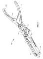
- FIG. 2is a perspective view of an exemplary embodiment of a bone fastener assembly instrument of the present disclosure in a collapsed configuration.
- FIG. 3is a perspective view of the bone fastener assembly instrument of FIG. 2 in a partially expanded configuration.
- FIG. 4is a perspective view of the bone fastener assembly instrument of FIG. 2 in a fully expanded configuration.
- FIG. 5Ais a partial top-down view of the bone fastener assembly instrument of FIG. 2 .
- FIG. 5Bis a partial top-down view of the bone fastener assembly instrument of FIG. 4 .
- FIG. 6is a perspective view of the bone fastener assembly instrument of FIG. 4 in cooperation with a tightening tool of the prior art.
- FIG. 7is an exploded view of the bone fastener assembly instrument of FIG. 2 .
- FIG. 8shows a perspective view of an exemplary embodiment of a transmission mechanism comprising gear wheels.
- FIG. 9shows a perspective view of an exemplary embodiment of a transmission mechanism comprising a rollerchain.
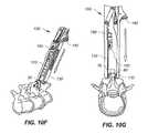
- FIGS. 10A-10Iillustrate an exemplary method of using the bone fastener assembly instrument of the present disclosure to assemble the bone fastener of FIG. 1B to the interlaminar-interspinous vertebral stabilization system of FIG. 1A .
- FIG. 1Ashows an implantable interlaminar-interspinous vertebral stabilization system 10 for stabilizing adjacent vertebrae
- FIG. 1Bshows a bone fastener for use with the stabilization system 10 , both of which are disclosed in U.S. Pat. No. 7,922,750.
- the prior art system 10comprises an implantable device 20 configured for placement between the spinous processes of adjacent vertebrae.
- the system 10can include one or more bone anchors 60 for securing the device 20 to spinous processes. Further, in one embodiment, the bone anchors 60 can rigidly fix the device 20 with respect to the spinous processes, thereby limiting movement at a selected vertebral level and promoting fusion at that level.
- the device 20may include a spacer body.
- the spacer body 20may have various shapes and thicknesses, and can be produced from a variety of different materials.
- the spacer body 20may include a midsection 30 extending between an inferior section 32 and a superior section 34 , as shown in FIG. 1A .
- the superior section 34is configured to contact a portion of a first spinous process
- the inferior section 32is configured to contact a portion of a second, adjacent spinous process.
- the midsection 30 , inferior section 32 , and superior section 34may together form a substantially U-shaped spacer body 20 , as shown.
- the spacer body 20may be configured to be flexible and/or bendable, such as, for example, by providing an extendable and/or compressible midsection 30 .
- the midsection 30can act as a flexible hinge, allowing the superior section 34 and inferior section 32 to move away from or towards one another.
- the U-shaped spacer bodyenables the device 10 to be positioned, or fitted, interlaminarly after implantation, thereby enhancing the stabilization of the adjacent vertebrae.
- the spacer body 20may be provided with a pair of lateral walls or brackets 36 that extend from the inferior and superior sections 32 , 34 , as shown in FIG. 1A .
- Each of the pair of lateral walls 36defines a stirrup 38 for receiving a spinous process.
- the spacer body 20can be provided with lateral walls 36 of various sizes or heights to accommodate variations in patient anatomy.
- the lateral walls 36 of different spacer bodies 20may be provided at differing locations along the length of the inferior section 32 or superior section 34 . The surgeon can thus select a suitably shaped and sized spacer body 20 depending on the particular vertebral level to be supported and the anatomy of the patient.
- the lateral walls 36may also be adjustable with respect to the spacer body 20 .
- the lateral walls 36may be formed of a malleable material such that, after implantation, the surgeon may compress the lateral walls 36 together to reduce the gap between the lateral walls 36 , thereby securely fixing the spacer body 20 to a spinous process located therein.
- the lateral walls 36may be spread apart to facilitate insertion, as illustrated with the inferiorly located lateral wall 36 of FIG. 1A .
- the lateral walls 36may be compressed or spread apart, for example, using surgical pliers or forceps.
- the lateral walls or brackets 36 of the present inventioncan also include an aperture 50 for receiving a bone fastener to fix the brackets 36 to the spinous process.
- Such fastening memberscan ensure that the brackets 36 are pressed flat and/or securely against the spinous process in order to avoid any play of the brackets 36 with respect to the process.
- the system 10may act as a fusion-promoting device when the implantable device 20 is fastened to the spinous process in this manner.
- the bone fastener 60can be of a two-component type that includes a bolt 70 comprising a head 72 and a threaded, elongate body 74 .
- a nut 80is provided having a head 82 , body portion 84 , and threaded inner cavity 86 for receiving the threaded, elongate body 74 of the bolt 70 .
- the lateral walls 36may be drawn together.
- the bone fastener 60 and spacer body 20may form a tight, secure connection with the spinous process.
- the tight, secure connection between the body 20 and adjacent spinous processeswill limit movement at the selected vertebral level, thereby promoting fusion at that level.
- the nut 80 and bolt 70may be tightened sufficiently to prevent the spacer body 20 from moving out of position between the spinous processes, but may be left sufficiently loose so as to allow a small amount of play between the spacer body 20 and spinous processes, so as not to promote fusion, or cause fusion to occur more slowly.
- the system 10can include two bone fasteners 60 , so that both the inferior and superior lateral walls 36 can be securely fastened to spinous processes.
- the device 20when positioned between the spinous processes of two adjacent vertebrae, may be secured to one spinous process and not the other spinous process, or to both adjacent spinous processes.
- the insertion tool 100may comprise a pair of handles 110 A, 110 B extending into gripping portions 112 .
- the gripping portions 112may include a surface modification such as for example bumps or raised portions 114 to provide a secure gripping surface for the user.
- the handles 110 A, 110 Bare connected to one another with a pivotable hinge 116 in a manner similar to scissors or pliers, much like the hinge described with the insertion tool of U.S. Pat. No. 7,922,750.
- a leaf spring 118may be positioned between the handles 110 A, 110 B, as further shown.
- Handle 110 Aextends into first arm 120 .
- the first arm 120includes an actuation or transmission mechanism 150 , shown in greater detail in the exploded view of FIG. 7 .
- the actuation or transmission mechanism 150may be detachable.
- the first arm 120may contain a depressed or cutaway portion 122 that allows the transmission mechanism 150 to fit inside the arm 120 .
- the transmission mechanism 150may include a series of gear wheels 152 that are actuated by means of port 160 . As shown in greater detail in FIG. 8 , the gear wheels are configured to move a drive train 158 , which can be configured as a drive chain, for example.
- FIG. 9illustrates another exemplary embodiment of a transmission mechanism 150 ′ that may be used interchangeably with transmission 150 .
- the transmission mechanism 150 ′may comprise a rollerchain 153 ′ that can be actuated by means of port 160 , similar to gear wheels 152 of FIG. 8 .
- rollerchain 153 ′may be configured to move drive train 158 ′.
- the transmission mechanism 150 ′ of the assembly instrument 100may be configured to work without friction under load.
- the assembly instrument 100 with the transmission mechanism 150 ′would offer the user the ability to close the bone fastener 60 without crimping the wings 36 of the implantable device 10 .
- a drive belt or Cardan shaftmay also be implemented as part of the transmission mechanism of the present disclosure.
- the transmission mechanism 150may include an aperture 154 that allows it to snap fit onto a depressible button 124 on the first arm 120 .
- a first component holding portion 156for holding one of the components of the bone fastener 60 .
- the first component holding portion 156may be configured to hold onto the bolt 70 .
- the transmission mechanism 150includes a port 160 configured to receive a tightening instrument 200 , shown in FIG. 6 .
- the tightening instrument 200may be of the type provided in U.S. Pat. No. 7,922,750 and configured to fit complementarily within port 160 , to actuate the transmission mechanism 150 and cause rotation of the bolt 70 .
- Handle 110 Bextends into a rail 170 onto which a second arm 130 may slidably connect.
- the second arm 130may include a second component holding portion 136 for holding the nut 80 of the bone fastener 60 .
- second arm 130may also include a projection 134 or finger rest that serves to move the second arm 130 , which can include notches that ratchet along the outside of the handle 110 A against the raised portions 114 . The notches help to keep the instrument 100 in the locked or collapsed configuration.
- the second arm 130may also be snap-fitted into place with the spring button 174 on the rail 170 and released by depressing a release button 140 on the instrument 100 .
- FIGS. 2 and 5Ashow the instrument 100 in a collapsed, or closed, position, wherein the width of the instrument 100 is in the range of about 15-25 mm, and preferably about 19 mm.
- FIG. 3illustrates the manner in which the instrument 100 can be expanded, or opened. As shown by the arrow, the user may press against the finger rest 134 to ratchet the second arm 130 away from the handle 110 A. When the second arm 130 is fully released, the arms 120 , 130 align, as shown in FIGS. 4 and 5B .
- the width of the instrument 100 in the released configurationis in the range of about 25-40 mm, and preferably about 32 mm.
- the bone fastener assembly instrument 100may be fully disassembled, as shown in FIG. 7 , by depressing the release button 140 as well as the spring buttons 124 , 174 . This allows all of the components to be sterilized and then re-assembled for future use.
- the implantable device 20is inserted between the spinous processes of adjacent vertebrae. Any appropriate surgical approach may be used to expose/visualize the spinous processes.
- a holecan be punched through the apertures 50 of each of the pair of lateral walls 36 , the apertures serving as a guide for placement of the hole through the spinous processes and allowing the bone fastener 60 to be positioned in the hole and through the spinous process.
- the holesmay be formed using, for example, a hole puncher.
- FIGS. 10A-10Iillustrate an exemplary method of using the bone fastener assembly instrument 100 of the present disclosure to assemble the prior art bone fastener 60 through the implantable device 20 of the prior art.
- the userAfter sterilizing the instrument 100 , the user attaches the components together by snapping the transmission mechanism 150 to the first arm 120 , and snapping the second arm 130 to the rail 170 .
- the bone fastener 60is loaded onto the instrument 100 in the expanded configuration, with the bolt 70 attached to the first component holding portion 156 of the transmission mechanism 150 , and the nut 80 attached to the second component holding portion of the second arm 130 .
- the instrument 100When the user is ready to assemble the bone fastener 60 together, the instrument 100 is first collapsed by sliding the arm 130 up to the end position, creating the slim profile configuration illustrated in FIG. 10A . In this collapsed configuration, the working ends of the arms as well as the handles are closed. With the bone fastener 60 loaded onto the instrument 100 , the user introduces the bolt 70 with the first arm 120 toward the target site, which in this example is the aperture 50 of the implantable device 20 . As indicated by the arrow in FIG. 10B , the user approaches the target site by aligning the attached bolt 70 to the target location.
- the instrument 100allows a starting approach that only requires one arm to be aligned, and allows the ability to have the other arm positioned away from the active site to keep the area clear and allow maximum visibility and work space, as represented in FIG. 10C .
- the instrument 100is released or expanded by sliding the second arm 130 down the end of the rail 170 to open up the working ends of the arms. As illustrated in FIGS. 10D and 10E , the second arm 130 may be slid down until the instrument 100 is fully expanded, thereby aligning the free ends of the arms 120 , 130 and consequently the attached nut 80 with the attached bolt 70 on opposed sides of the implantable device 20 , as shown in a different angle at FIGS. 10F and 10G .
- a tightening instrument 200 of the kind described in U.S. Pat. No. 7,922,750can be placed into the port 160 .
- Turning the tightening instrument 200causes the actuation of the transmission mechanism 150 and rotation of the bolt 70 , thereby causing the threading of the bolt 70 into the nut 80 , as shown in FIGS. 10H and 10I .
- the assembly instrument 100facilitates alignment and threading of the bolt 70 and nut 80 .
- the assembly instrument 100maintains the bolt 70 and nut 80 in the properly aligned position so as to ensure that they easily thread together during assembly, while also providing a space-saving solution of allowing one arm to be extended and one arm to be retracted in the initial approach.
- the assembly instrumentallows for quick rotation of the bolt 70 to secure the components to one another.
- a maximum of 7 to 10 rotations of the tightening instrument 200and more preferably not more than 9 rotations, are required to complete the assembly process.
- the transmission mechanism 150may be configured with an inside transmission ratio of 2:1, for example, for a very fast assembly time. Of course, other transmission ratios may be utilized as well.
- one or more additional instrumentsmay be provided to assist in positioning the spinous processes of the vertebrae to be treated.
- one or more additional instrumentsmay be provided to assist in positioning the spinous processes of the vertebrae to be treated.
- a pair of compression pliersmay be provided to assist the surgeon in producing the desired degree of lordosis.
Landscapes
- Health & Medical Sciences (AREA)
- Orthopedic Medicine & Surgery (AREA)
- Surgery (AREA)
- Life Sciences & Earth Sciences (AREA)
- Heart & Thoracic Surgery (AREA)
- Nuclear Medicine, Radiotherapy & Molecular Imaging (AREA)
- Engineering & Computer Science (AREA)
- Biomedical Technology (AREA)
- Medical Informatics (AREA)
- Molecular Biology (AREA)
- Animal Behavior & Ethology (AREA)
- General Health & Medical Sciences (AREA)
- Public Health (AREA)
- Veterinary Medicine (AREA)
- Neurology (AREA)
- Prostheses (AREA)
- Surgical Instruments (AREA)
Abstract
Description
Claims (15)
Priority Applications (1)
| Application Number | Priority Date | Filing Date | Title |
|---|---|---|---|
| US13/949,574US9173695B2 (en) | 2012-07-24 | 2013-07-24 | Bone fastener assembly instrument |
Applications Claiming Priority (3)
| Application Number | Priority Date | Filing Date | Title |
|---|---|---|---|
| US201261675222P | 2012-07-24 | 2012-07-24 | |
| US201361784254P | 2013-03-14 | 2013-03-14 | |
| US13/949,574US9173695B2 (en) | 2012-07-24 | 2013-07-24 | Bone fastener assembly instrument |
Publications (2)
| Publication Number | Publication Date |
|---|---|
| US20140031830A1 US20140031830A1 (en) | 2014-01-30 |
| US9173695B2true US9173695B2 (en) | 2015-11-03 |
Family
ID=49995569
Family Applications (1)
| Application Number | Title | Priority Date | Filing Date |
|---|---|---|---|
| US13/949,574Active2034-02-19US9173695B2 (en) | 2012-07-24 | 2013-07-24 | Bone fastener assembly instrument |
Country Status (1)
| Country | Link |
|---|---|
| US (1) | US9173695B2 (en) |
Cited By (1)
| Publication number | Priority date | Publication date | Assignee | Title |
|---|---|---|---|---|
| US11504168B2 (en)* | 2019-12-20 | 2022-11-22 | Paradigm Spine, Llc | Bone fastener assembly instrument |
Families Citing this family (2)
| Publication number | Priority date | Publication date | Assignee | Title |
|---|---|---|---|---|
| US9173695B2 (en)* | 2012-07-24 | 2015-11-03 | Paradigm Spine, Llc | Bone fastener assembly instrument |
| US10702290B2 (en)* | 2015-11-02 | 2020-07-07 | First Ray, LLC | Orthopedic fastener, retainer, and guide |
Citations (45)
| Publication number | Priority date | Publication date | Assignee | Title |
|---|---|---|---|---|
| US3604487A (en)* | 1969-03-10 | 1971-09-14 | Richard S Gilbert | Orthopedic screw driving means |
| US4033043A (en)* | 1975-07-09 | 1977-07-05 | Cunningham Frank W | Gauge for measuring length of an opening |
| US5133715A (en)* | 1991-02-04 | 1992-07-28 | Lenzo Salvatore R | Surgical device for open reduction of bone fractures |
| US5226906A (en)* | 1991-02-13 | 1993-07-13 | Howmedica, Inc. | Surgical speed wrench |
| US5236053A (en)* | 1992-05-15 | 1993-08-17 | Aseptico, Incorporated | Torque system |
| US5445641A (en)* | 1991-05-10 | 1995-08-29 | Synthes | Storage and dispensing device for osteosynthetic fixation elements |
| US5458603A (en)* | 1993-05-12 | 1995-10-17 | Futch, Sr.; William A. | Elongated drive tool for prosthesis in body cavity |
| US5626474A (en)* | 1995-06-28 | 1997-05-06 | Kukla; Thomas S. | Implant torque wrench |
| US5997545A (en)* | 1998-11-06 | 1999-12-07 | Johnson & Johnson Professional, Inc. | Knee incision tensile gauge |
| DE19828137A1 (en) | 1998-06-24 | 2000-01-05 | Med Medical Engineering Dev Lt | Osteo-synthesis tongs for pedicle screws or other implants |
| US6330845B1 (en)* | 2000-05-17 | 2001-12-18 | Bristol-Myers Squibb | Wrench for an implant |
| US6436123B1 (en)* | 1998-01-13 | 2002-08-20 | Cardiacassist, Inc. | System apparatus and method for closing severed bone or tissue of a patient |
| US6511484B2 (en)* | 2001-06-29 | 2003-01-28 | Depuy Acromed, Inc. | Tool and system for aligning and applying fastener to implanted anchor |
| US20030040746A1 (en)* | 2001-07-20 | 2003-02-27 | Mitchell Margaret E. | Spinal stabilization system and method |
| US20030236529A1 (en)* | 2002-06-24 | 2003-12-25 | Endius Incorporated | Surgical instrument for moving vertebrae |
| US6669698B1 (en)* | 2000-10-24 | 2003-12-30 | Sdgi Holdings, Inc. | Vertebrae fastener placement guide |
| US20040106927A1 (en)* | 2002-03-01 | 2004-06-03 | Ruffner Brian M. | Vertebral distractor |
| US6752832B2 (en)* | 2000-12-27 | 2004-06-22 | Ulrich Gmbh & Co., Kg | Vertebral implant and setting tool therefor |
| US20050137608A1 (en)* | 2000-07-27 | 2005-06-23 | Synthes (Usa) | Cranial flap clamp instrument |
| WO2007021850A1 (en) | 2005-08-12 | 2007-02-22 | Smith & Nephew, Inc. | Fastener retainer and driver |
| US7207995B1 (en)* | 2004-01-29 | 2007-04-24 | Biomer Manufacturing Corp. | Method and apparatus for retaining a guide wire |
| US7563275B2 (en)* | 2002-10-10 | 2009-07-21 | U.S. Spinal Technologies, Llc | Bone fixation implant system and method |
| US20090259262A1 (en)* | 2008-04-15 | 2009-10-15 | Warsaw Orthopedic, Inc. | Surgical tool |
| US7608094B2 (en)* | 2002-10-10 | 2009-10-27 | U.S. Spinal Technologies, Llc | Percutaneous facet fixation system |
| US20100076490A1 (en)* | 2008-02-28 | 2010-03-25 | Jonathan Greenwald | Facet joint broaching instrument, implant, and associated method |
| US20100262198A1 (en)* | 2009-03-26 | 2010-10-14 | Reto Braunschweiler | Instrument set for inserting a stabilization system into the spinal column of a body |
| US20110034961A1 (en)* | 2007-07-26 | 2011-02-10 | Depuy Spine, Inc. | Spinal rod reduction instruments and methods for use |
| US20110040341A1 (en)* | 2005-10-31 | 2011-02-17 | Depuy Spine, Inc. | Arthroplasty revision device and method |
| US7922750B2 (en)* | 2006-11-30 | 2011-04-12 | Paradigm Spine, Llc | Interlaminar-interspinous vertebral stabilization system |
| US20110106091A1 (en)* | 2009-11-02 | 2011-05-05 | Synvasive Technology, Inc. | Knee arthroplasty apparatus and method |
| US20110172722A1 (en)* | 2005-09-29 | 2011-07-14 | Depuy Spine, Inc. | Motion Segment Repair Systems and Methods |
| US8002812B2 (en)* | 2002-10-10 | 2011-08-23 | Us Spine, Inc. | Bone fixation implant system and method |
| US20110224740A1 (en)* | 2010-03-12 | 2011-09-15 | Southern Spine, Llc | Implantation Tools for Interspinous Process Spacing Device |
| US20110313323A1 (en)* | 2007-01-29 | 2011-12-22 | Polaris Biotechnology, Inc. | Method for treating a neurological disorder |
| US20110319936A1 (en)* | 2009-06-23 | 2011-12-29 | Osteomed Llc | Spinous process fusion implants and insertion, compression, and locking instrumentation |
| US8105329B2 (en)* | 2005-01-26 | 2012-01-31 | Warsaw Orthopedic, Inc. | Reducing instrument for spinal surgery |
| US8167885B2 (en)* | 2007-12-05 | 2012-05-01 | Pat Barrett | Anterior lumbar interbody graft inserter |
| US8216241B2 (en)* | 2005-06-02 | 2012-07-10 | Depuy Spine, Inc. | Instruments and methods for manipulating a spinal fixation element |
| US20120277810A1 (en)* | 2011-04-29 | 2012-11-01 | Medacta International Sa | Instrument for positioning an intervertebral implant for the fusion between two vertebral bodies of a vertebral column |
| US8323292B2 (en)* | 2008-12-15 | 2012-12-04 | Spinecore, Inc. | Adjustable pin drill guide and methods therefor |
| US20130066385A1 (en)* | 2011-09-14 | 2013-03-14 | Warsaw Orthopedic, Inc. | Connecting element reduction instrument and methods for using same |
| US20130096625A1 (en)* | 2009-10-14 | 2013-04-18 | K2M, Inc. | Surgical rod scorer and method of use of the same |
| US20140031830A1 (en)* | 2012-07-24 | 2014-01-30 | Paradigm Spine, Llc | Bone fastener assembly instrument |
| US8685065B1 (en)* | 2012-04-20 | 2014-04-01 | Lanx, Inc. | Tools for implantation of interspinous implants and methods thereof |
| US20140249591A1 (en)* | 2013-03-01 | 2014-09-04 | Warsaw Orthopedic, Inc. | Spinal correction system and method |
- 2013
- 2013-07-24USUS13/949,574patent/US9173695B2/enactiveActive
Patent Citations (49)
| Publication number | Priority date | Publication date | Assignee | Title |
|---|---|---|---|---|
| US3604487A (en)* | 1969-03-10 | 1971-09-14 | Richard S Gilbert | Orthopedic screw driving means |
| US4033043A (en)* | 1975-07-09 | 1977-07-05 | Cunningham Frank W | Gauge for measuring length of an opening |
| US5133715A (en)* | 1991-02-04 | 1992-07-28 | Lenzo Salvatore R | Surgical device for open reduction of bone fractures |
| US5226906A (en)* | 1991-02-13 | 1993-07-13 | Howmedica, Inc. | Surgical speed wrench |
| US5445641A (en)* | 1991-05-10 | 1995-08-29 | Synthes | Storage and dispensing device for osteosynthetic fixation elements |
| US5236053A (en)* | 1992-05-15 | 1993-08-17 | Aseptico, Incorporated | Torque system |
| US5458603A (en)* | 1993-05-12 | 1995-10-17 | Futch, Sr.; William A. | Elongated drive tool for prosthesis in body cavity |
| US5626474A (en)* | 1995-06-28 | 1997-05-06 | Kukla; Thomas S. | Implant torque wrench |
| US6436123B1 (en)* | 1998-01-13 | 2002-08-20 | Cardiacassist, Inc. | System apparatus and method for closing severed bone or tissue of a patient |
| DE19828137A1 (en) | 1998-06-24 | 2000-01-05 | Med Medical Engineering Dev Lt | Osteo-synthesis tongs for pedicle screws or other implants |
| US5997545A (en)* | 1998-11-06 | 1999-12-07 | Johnson & Johnson Professional, Inc. | Knee incision tensile gauge |
| US6330845B1 (en)* | 2000-05-17 | 2001-12-18 | Bristol-Myers Squibb | Wrench for an implant |
| US20050137608A1 (en)* | 2000-07-27 | 2005-06-23 | Synthes (Usa) | Cranial flap clamp instrument |
| US6669698B1 (en)* | 2000-10-24 | 2003-12-30 | Sdgi Holdings, Inc. | Vertebrae fastener placement guide |
| US6752832B2 (en)* | 2000-12-27 | 2004-06-22 | Ulrich Gmbh & Co., Kg | Vertebral implant and setting tool therefor |
| US6511484B2 (en)* | 2001-06-29 | 2003-01-28 | Depuy Acromed, Inc. | Tool and system for aligning and applying fastener to implanted anchor |
| US20030040746A1 (en)* | 2001-07-20 | 2003-02-27 | Mitchell Margaret E. | Spinal stabilization system and method |
| US20080140125A1 (en)* | 2001-07-20 | 2008-06-12 | Mitchell Margaret E | Spinal stabilization system and method |
| US20040106927A1 (en)* | 2002-03-01 | 2004-06-03 | Ruffner Brian M. | Vertebral distractor |
| US20030236529A1 (en)* | 2002-06-24 | 2003-12-25 | Endius Incorporated | Surgical instrument for moving vertebrae |
| US7608094B2 (en)* | 2002-10-10 | 2009-10-27 | U.S. Spinal Technologies, Llc | Percutaneous facet fixation system |
| US7563275B2 (en)* | 2002-10-10 | 2009-07-21 | U.S. Spinal Technologies, Llc | Bone fixation implant system and method |
| US8002812B2 (en)* | 2002-10-10 | 2011-08-23 | Us Spine, Inc. | Bone fixation implant system and method |
| US7207995B1 (en)* | 2004-01-29 | 2007-04-24 | Biomer Manufacturing Corp. | Method and apparatus for retaining a guide wire |
| US8105329B2 (en)* | 2005-01-26 | 2012-01-31 | Warsaw Orthopedic, Inc. | Reducing instrument for spinal surgery |
| US20120253413A1 (en) | 2005-06-02 | 2012-10-04 | Depuy Spine, Inc | Instruments and methods for manipulating a spinal fixation element |
| US8216241B2 (en)* | 2005-06-02 | 2012-07-10 | Depuy Spine, Inc. | Instruments and methods for manipulating a spinal fixation element |
| WO2007021850A1 (en) | 2005-08-12 | 2007-02-22 | Smith & Nephew, Inc. | Fastener retainer and driver |
| US20110172722A1 (en)* | 2005-09-29 | 2011-07-14 | Depuy Spine, Inc. | Motion Segment Repair Systems and Methods |
| US20110040341A1 (en)* | 2005-10-31 | 2011-02-17 | Depuy Spine, Inc. | Arthroplasty revision device and method |
| US20110190819A1 (en)* | 2006-11-30 | 2011-08-04 | Paradigm Spine, Llc | Interlaminar-interspinous vertebral stabilization system |
| US7922750B2 (en)* | 2006-11-30 | 2011-04-12 | Paradigm Spine, Llc | Interlaminar-interspinous vertebral stabilization system |
| US20110313323A1 (en)* | 2007-01-29 | 2011-12-22 | Polaris Biotechnology, Inc. | Method for treating a neurological disorder |
| US20110034961A1 (en)* | 2007-07-26 | 2011-02-10 | Depuy Spine, Inc. | Spinal rod reduction instruments and methods for use |
| US8167885B2 (en)* | 2007-12-05 | 2012-05-01 | Pat Barrett | Anterior lumbar interbody graft inserter |
| US20100076490A1 (en)* | 2008-02-28 | 2010-03-25 | Jonathan Greenwald | Facet joint broaching instrument, implant, and associated method |
| US20090259262A1 (en)* | 2008-04-15 | 2009-10-15 | Warsaw Orthopedic, Inc. | Surgical tool |
| US8323292B2 (en)* | 2008-12-15 | 2012-12-04 | Spinecore, Inc. | Adjustable pin drill guide and methods therefor |
| US20100262198A1 (en)* | 2009-03-26 | 2010-10-14 | Reto Braunschweiler | Instrument set for inserting a stabilization system into the spinal column of a body |
| US20110319936A1 (en)* | 2009-06-23 | 2011-12-29 | Osteomed Llc | Spinous process fusion implants and insertion, compression, and locking instrumentation |
| US20130096625A1 (en)* | 2009-10-14 | 2013-04-18 | K2M, Inc. | Surgical rod scorer and method of use of the same |
| US20110106091A1 (en)* | 2009-11-02 | 2011-05-05 | Synvasive Technology, Inc. | Knee arthroplasty apparatus and method |
| US20110224740A1 (en)* | 2010-03-12 | 2011-09-15 | Southern Spine, Llc | Implantation Tools for Interspinous Process Spacing Device |
| US20120310292A1 (en) | 2010-03-12 | 2012-12-06 | Southern Spine, Llc | Implantation Tools for Interspinous Process Spacing Device |
| US20120277810A1 (en)* | 2011-04-29 | 2012-11-01 | Medacta International Sa | Instrument for positioning an intervertebral implant for the fusion between two vertebral bodies of a vertebral column |
| US20130066385A1 (en)* | 2011-09-14 | 2013-03-14 | Warsaw Orthopedic, Inc. | Connecting element reduction instrument and methods for using same |
| US8685065B1 (en)* | 2012-04-20 | 2014-04-01 | Lanx, Inc. | Tools for implantation of interspinous implants and methods thereof |
| US20140031830A1 (en)* | 2012-07-24 | 2014-01-30 | Paradigm Spine, Llc | Bone fastener assembly instrument |
| US20140249591A1 (en)* | 2013-03-01 | 2014-09-04 | Warsaw Orthopedic, Inc. | Spinal correction system and method |
Cited By (1)
| Publication number | Priority date | Publication date | Assignee | Title |
|---|---|---|---|---|
| US11504168B2 (en)* | 2019-12-20 | 2022-11-22 | Paradigm Spine, Llc | Bone fastener assembly instrument |
Also Published As
| Publication number | Publication date |
|---|---|
| US20140031830A1 (en) | 2014-01-30 |
Similar Documents
| Publication | Publication Date | Title |
|---|---|---|
| AU2007325094B2 (en) | Interlaminar-interspinous vertebral stabilization system | |
| US11504168B2 (en) | Bone fastener assembly instrument | |
| US8444649B2 (en) | System and method for manipulating a spinal construct | |
| US7578822B2 (en) | Instrument for compression or distraction | |
| US11350973B2 (en) | Rod reducer | |
| US11051858B2 (en) | Instruments for interspinous or interlaminar stabilization devices | |
| US10524843B2 (en) | Rotation shaft for a rod reducer | |
| JP7137792B2 (en) | Devices for treating spinous processes | |
| US9173695B2 (en) | Bone fastener assembly instrument | |
| US20210322065A1 (en) | Systems, methods of use and surgical instruments employing a secure slide lock to fasten a head | |
| AU2016235005B2 (en) | Interlaminar-Interspinous Vertebral Stabilization System | |
| AU2014200937B2 (en) | Interlaminar-Interspinous Vertebral Stabilization System | |
| HK1140121B (en) | Interlaminar-interspinous vertebral stabilization system |
Legal Events
| Date | Code | Title | Description |
|---|---|---|---|
| AS | Assignment | Owner name:PARADIGM SPINE, LLC, NEW YORK Free format text:ASSIGNMENT OF ASSIGNORS INTEREST;ASSIGNORS:SALVERMOSER, MARKUS;ECKHOF, STEPHAN;MUCKENFUSS, SVEN OLIVER;AND OTHERS;SIGNING DATES FROM 20130903 TO 20130912;REEL/FRAME:031218/0979 | |
| AS | Assignment | Owner name:PDL BIOPHARMA, INC., NEVADA Free format text:SECURITY AGREEMENT;ASSIGNORS:PARADIGM SPINE, LLC;FOURTH DIMENSION SPINE, LLC;REEL/FRAME:032264/0866 Effective date:20140214 | |
| AS | Assignment | Owner name:FOURTH DIMENSION SPINE, LLC, NEW YORK Free format text:RELEASE BY SECURED PARTY;ASSIGNOR:SIGULER GUFF DISTRESSED OPPORTUNITIES FUND III, LP;REEL/FRAME:032275/0711 Effective date:20140214 Owner name:PARADIGM SPINE, LLC, NEW YORK Free format text:RELEASE BY SECURED PARTY;ASSIGNOR:SIGULER GUFF DISTRESSED OPPORTUNITIES FUND III, LP;REEL/FRAME:032275/0711 Effective date:20140214 | |
| FEPP | Fee payment procedure | Free format text:PAYOR NUMBER ASSIGNED (ORIGINAL EVENT CODE: ASPN); ENTITY STATUS OF PATENT OWNER: LARGE ENTITY | |
| STCF | Information on status: patent grant | Free format text:PATENTED CASE | |
| AS | Assignment | Owner name:PARADIGM SPINE, LLC, NEW YORK Free format text:RELEASE BY SECURED PARTY;ASSIGNOR:PDL BIOPHARMA, INC.;REEL/FRAME:039556/0012 Effective date:20160826 Owner name:FOURTH DIMENSION SPINE, LLC, NEW YORK Free format text:RELEASE BY SECURED PARTY;ASSIGNOR:PDL BIOPHARMA, INC.;REEL/FRAME:039556/0012 Effective date:20160826 Owner name:HAYFIN SERVICES LLP, UNITED KINGDOM Free format text:SECURITY INTEREST;ASSIGNOR:PARADIGM SPINE, LLC;REEL/FRAME:039842/0877 Effective date:20160826 | |
| AS | Assignment | Owner name:JPMORGAN CHASE BANK, N.A., AS ADMINISTRATIVE AGENT, ILLINOIS Free format text:SECURITY INTEREST;ASSIGNORS:PARADIGM SPINE, LLC;FOURTH DIMENSION SPINE, LLC;REEL/FRAME:048538/0026 Effective date:20190308 Owner name:JPMORGAN CHASE BANK, N.A., AS ADMINISTRATIVE AGENT Free format text:SECURITY INTEREST;ASSIGNORS:PARADIGM SPINE, LLC;FOURTH DIMENSION SPINE, LLC;REEL/FRAME:048538/0026 Effective date:20190308 Owner name:ARES CAPITAL CORPORATION, AS ADMINISTRATIVE AGENT, Free format text:SECURITY INTEREST;ASSIGNORS:RTI SURGICAL, INC.;PIONEER SURGICAL TECHNOLOGY, INC.;TUTOGEN MEDICAL, INC.;AND OTHERS;REEL/FRAME:048543/0505 Effective date:20190308 Owner name:ARES CAPITAL CORPORATION, AS ADMINISTRATIVE AGENT, NEW YORK Free format text:SECURITY INTEREST;ASSIGNORS:RTI SURGICAL, INC.;PIONEER SURGICAL TECHNOLOGY, INC.;TUTOGEN MEDICAL, INC.;AND OTHERS;REEL/FRAME:048543/0505 Effective date:20190308 | |
| AS | Assignment | Owner name:PARADIGM SPINE, LLC, NEW YORK Free format text:RELEASE BY SECURED PARTY;ASSIGNOR:HAYFIN SERVICES LLP, AS ADMINISTRATIVE AGENT;REEL/FRAME:050426/0001 Effective date:20190308 | |
| FEPP | Fee payment procedure | Free format text:ENTITY STATUS SET TO UNDISCOUNTED (ORIGINAL EVENT CODE: BIG.); ENTITY STATUS OF PATENT OWNER: LARGE ENTITY | |
| MAFP | Maintenance fee payment | Free format text:PAYMENT OF MAINTENANCE FEE, 4TH YEAR, LARGE ENTITY (ORIGINAL EVENT CODE: M1551); ENTITY STATUS OF PATENT OWNER: LARGE ENTITY Year of fee payment:4 | |
| AS | Assignment | Owner name:PARADIGM SPINE, LLC, NEW YORK Free format text:TERMINATION AND RELEASE OF SECURITY INTEREST IN PATENTS;ASSIGNOR:HAYFIN SERVICES LLP;REEL/FRAME:050236/0828 Effective date:20190308 | |
| AS | Assignment | Owner name:RTI SURGICAL, INC., FLORIDA Free format text:RELEASE BY SECURED PARTY;ASSIGNOR:ARES CAPITAL CORPORATION, AS AGENT;REEL/FRAME:053257/0652 Effective date:20200720 Owner name:PARADIGM SPINE, LLC, NEW YORK Free format text:RELEASE BY SECURED PARTY;ASSIGNOR:ARES CAPITAL CORPORATION, AS AGENT;REEL/FRAME:053257/0652 Effective date:20200720 Owner name:FOURTH DIMENSION SPINE, LLC, NEW YORK Free format text:RELEASE BY SECURED PARTY;ASSIGNOR:ARES CAPITAL CORPORATION, AS AGENT;REEL/FRAME:053257/0652 Effective date:20200720 Owner name:TUTOGEN MEDICAL, INC., FLORIDA Free format text:RELEASE BY SECURED PARTY;ASSIGNOR:ARES CAPITAL CORPORATION, AS AGENT;REEL/FRAME:053257/0652 Effective date:20200720 Owner name:PIONEER SURGICAL TECHNOLOGY, INC., FLORIDA Free format text:RELEASE BY SECURED PARTY;ASSIGNOR:ARES CAPITAL CORPORATION, AS AGENT;REEL/FRAME:053257/0652 Effective date:20200720 | |
| AS | Assignment | Owner name:FOURTH DIMENSION SPINE, LLC, FLORIDA Free format text:RELEASE BY SECURED PARTY;ASSIGNOR:JPMORGAN CHASE BANK, N.A., AS ADMINISTRATIVE AGENT;REEL/FRAME:053260/0156 Effective date:20200720 Owner name:PARADIGM SPINE, LLC, FLORIDA Free format text:RELEASE BY SECURED PARTY;ASSIGNOR:JPMORGAN CHASE BANK, N.A., AS ADMINISTRATIVE AGENT;REEL/FRAME:053260/0156 Effective date:20200720 | |
| AS | Assignment | Owner name:SURGALIGN SPV, INC., MONTANA Free format text:ASSIGNMENT OF ASSIGNORS INTEREST;ASSIGNOR:PARADIGM SPINE, LLC;REEL/FRAME:063234/0268 Effective date:20230228 | |
| AS | Assignment | Owner name:MIDCAP FINANCIAL TRUST, MARYLAND Free format text:SECURITY AGREEMENT (TERM);ASSIGNOR:SURGALIGN SPV, INC.;REEL/FRAME:063281/0903 Effective date:20230406 Owner name:MIDCAP FUNDING IV TRUST, MARYLAND Free format text:SECURITY AGREEMENT (REVOLVING);ASSIGNOR:SURGALIGN SPV, INC.;REEL/FRAME:063281/0856 Effective date:20230406 | |
| MAFP | Maintenance fee payment | Free format text:PAYMENT OF MAINTENANCE FEE, 8TH YEAR, LARGE ENTITY (ORIGINAL EVENT CODE: M1552); ENTITY STATUS OF PATENT OWNER: LARGE ENTITY Year of fee payment:8 | |
| AS | Assignment | Owner name:XTANT MEDICAL, INC., MONTANA Free format text:ASSIGNMENT OF ASSIGNORS INTEREST;ASSIGNOR:SURGALIGN SPV, INC.;REEL/FRAME:063435/0150 Effective date:20230406 |