US9173686B2 - Interspinous implant - Google Patents
Interspinous implantDownload PDFInfo
- Publication number
- US9173686B2 US9173686B2US11/746,204US74620407AUS9173686B2US 9173686 B2US9173686 B2US 9173686B2US 74620407 AUS74620407 AUS 74620407AUS 9173686 B2US9173686 B2US 9173686B2
- Authority
- US
- United States
- Prior art keywords
- shaped
- implant
- leg
- legs
- pair
- Prior art date
- Legal status (The legal status is an assumption and is not a legal conclusion. Google has not performed a legal analysis and makes no representation as to the accuracy of the status listed.)
- Active, expires
Links
- 239000007943implantSubstances0.000titleclaimsabstractdescription116
- 238000000034methodMethods0.000claimsabstractdescription33
- 230000015572biosynthetic processEffects0.000claimsdescription7
- 238000005755formation reactionMethods0.000claimsdescription7
- 210000003041ligamentAnatomy0.000description9
- 210000000988bone and boneAnatomy0.000description8
- 239000000463materialSubstances0.000description4
- 239000002184metalSubstances0.000description4
- 229910052751metalInorganic materials0.000description4
- 230000007613environmental effectEffects0.000description3
- 238000003780insertionMethods0.000description3
- 230000037431insertionEffects0.000description3
- 239000004696Poly ether ether ketoneSubstances0.000description2
- RTAQQCXQSZGOHL-UHFFFAOYSA-NTitaniumChemical compound[Ti]RTAQQCXQSZGOHL-UHFFFAOYSA-N0.000description2
- JUPQTSLXMOCDHR-UHFFFAOYSA-Nbenzene-1,4-diol;bis(4-fluorophenyl)methanoneChemical compoundOC1=CC=C(O)C=C1.C1=CC(F)=CC=C1C(=O)C1=CC=C(F)C=C1JUPQTSLXMOCDHR-UHFFFAOYSA-N0.000description2
- 150000002739metalsChemical class0.000description2
- 239000004033plasticSubstances0.000description2
- 229920002530polyetherether ketonePolymers0.000description2
- 239000010936titaniumSubstances0.000description2
- 229910052719titaniumInorganic materials0.000description2
- 239000004677NylonSubstances0.000description1
- 210000003484anatomyAnatomy0.000description1
- 230000003042antagnostic effectEffects0.000description1
- 239000000560biocompatible materialSubstances0.000description1
- 238000007906compressionMethods0.000description1
- 238000010276constructionMethods0.000description1
- 238000002788crimpingMethods0.000description1
- 238000002224dissectionMethods0.000description1
- 238000000605extractionMethods0.000description1
- -1for exampleChemical class0.000description1
- 239000012634fragmentSubstances0.000description1
- 230000004927fusionEffects0.000description1
- 238000002513implantationMethods0.000description1
- 239000007769metal materialSubstances0.000description1
- 238000012986modificationMethods0.000description1
- 230000004048modificationEffects0.000description1
- 229920001778nylonPolymers0.000description1
- 210000004872soft tissueAnatomy0.000description1
- 208000005198spinal stenosisDiseases0.000description1
Images


Classifications
- A—HUMAN NECESSITIES
- A61—MEDICAL OR VETERINARY SCIENCE; HYGIENE
- A61B—DIAGNOSIS; SURGERY; IDENTIFICATION
- A61B17/00—Surgical instruments, devices or methods
- A61B17/56—Surgical instruments or methods for treatment of bones or joints; Devices specially adapted therefor
- A61B17/58—Surgical instruments or methods for treatment of bones or joints; Devices specially adapted therefor for osteosynthesis, e.g. bone plates, screws or setting implements
- A61B17/68—Internal fixation devices, including fasteners and spinal fixators, even if a part thereof projects from the skin
- A61B17/70—Spinal positioners or stabilisers, e.g. stabilisers comprising fluid filler in an implant
- A61B17/7062—Devices acting on, attached to, or simulating the effect of, vertebral processes, vertebral facets or ribs ; Tools for such devices
- A61B2019/461—
- A—HUMAN NECESSITIES
- A61—MEDICAL OR VETERINARY SCIENCE; HYGIENE
- A61B—DIAGNOSIS; SURGERY; IDENTIFICATION
- A61B90/00—Instruments, implements or accessories specially adapted for surgery or diagnosis and not covered by any of the groups A61B1/00 - A61B50/00, e.g. for luxation treatment or for protecting wound edges
- A61B90/06—Measuring instruments not otherwise provided for
- A61B2090/061—Measuring instruments not otherwise provided for for measuring dimensions, e.g. length
Definitions
- interspinous implantsare known for correcting damaged intervertebral disks or other conditions that can subject the spinous processes of adjacent vertebrae to stresses, overextension, painful wear and tear, or general instability of the spinal column.
- the present teachingsprovide an interspinous implant that can stabilize the spine and limit overextension of the spine and excessive spacing between the superior and inferior processes.
- the present teachingsprovide an interspinous implant that includes a substantially S-shaped body having a longitudinal anterior-posterior axis and first and second ends, a first U-shaped extension attached to the first end, and a second U-shaped extension attached to the second end.
- the first and second extensionscan be oriented at an angle relative to the anterior-posterior axis and engageable to first and second spinous processes.
- the second extensioncan be offset relative to the first extension along the anterior-posterior axis.
- the S-shaped bodycan be resilient and can include a first portion having first and second ends and being substantially U-shaped, a second portion having first and second ends and being substantially U-shaped, and an intermediate portion connecting the second end of the first portion and the first end of the second portion.
- the present teachingsalso provide an interspinous implant that includes a resilient S-shaped body including first and second saddle-shaped portions, and first and second stirrup-shaped brackets extending at an angle and in opposite directions from the first and second saddle-shaped portions.
- the first and second stirrup-shaped bracketscan engage first and second spinous processes.
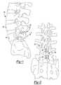
- FIG. 1is a side view of an interspinous implant according to the present teachings, the interspinous implant shown implanted in a spine;
- FIG. 2is a rear view of the interspinous implant of FIG. 1 , the interspinous implant shown implanted in a spine;
- FIG. 3is a side view of two interspinous implants according to the present teachings, the interspinous implants shown implanted in a spine;
- FIG. 4is a perspective view of an interspinous implant according to the present teachings.
- FIG. 5is a rear view of the interspinous implant of FIG. 4 ;
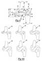
- FIG. 6is a side view of the interspinous implant of FIG. 4 , shown in a first configuration
- FIG. 6Aillustrates side views of a series of representative interspinous implants according to the present teachings
- FIG. 7is a side view of the interspinous implant of FIG. 4 , shown in a second configuration
- FIG. 7Ais a side view of the interspinous implant of FIG. 4 , shown in a second configuration
- FIG. 8is a perspective view of an interspinous implant according to the present teachings.
- FIG. 9is a side view of the interspinous implant of FIG. 8 ;
- FIG. 10is a rear view of the interspinous implant of FIG. 8 ;
- FIG. 11is a perspective view of an interspinous implant according to the present teachings.
- FIG. 12is a side view of the interspinous implant of FIG. 11 ;
- FIG. 13is a perspective view of an interspinous implant according to the present teachings.
- FIG. 13Ais a rear view of the interspinous implant of FIG. 13 ;
- FIG. 13Bis a side view of the interspinous implant of FIG. 13 ;
- FIG. 14is an environmental view of an interspinous implant according to the present teachings, the interspinous implant shown implanted in a spine;
- FIG. 14Ais a rear view of the interspinous implant of FIG. 14 ;
- FIG. 14Bis a side view of the interspinous implant of FIG. 14 ;
- FIG. 14Cis a front view of the interspinous implant of FIG. 14 ;
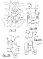
- FIG. 15is an environmental view of an interspinous implant according to the present teachings, the interspinous implant shown implanted in a spine;
- FIG. 15Ais a rear view of the interspinous implant of FIG. 15 ;
- FIG. 15Bis a side view of the interspinous implant of FIG. 15 ;
- FIG. 16is an environmental view of an interspinous implant according to the present teachings, the interspinous implant shown implanted in a spine;
- FIG. 16Ais a rear view of the interspinous implant of FIG. 16 ;
- FIG. 16Bis a side view of the interspinous implant of FIG. 16 ;
- FIG. 16Cis a front view of the interspinous implant of FIG. 16 ;
- FIG. 17Ais rear view of an interspinous implant according to the present teachings.
- FIG. 17Bis a side view of the interspinous implant of FIG. 17A ;
- FIG. 17Cis a front view of the interspinous implant of FIG. 17A ;
- FIG. 18Ais a perspective view of an inserter for an interspinous implant according to the present teachings, the inserter shown holding the interspinous implant;
- FIG. 18Bis an exploded view of the inserter of FIG. 18A ;
- FIG. 19Ais a perspective view of an inserter for an interspinous implant according to the present teachings.
- FIG. 19Bis a perspective view of the inserter of FIG. 19A , the inserter shown holding the interspinous implant;
- FIG. 20Ais a perspective view of an inserter for an interspinous implant according to the present teachings.
- FIG. 20Bis an exploded view of the inserter of FIG. 20A ;
- FIG. 21Ais a perspective view of a trial sizer for an interspinous implant according to the present teachings.
- FIG. 21Bis a side view of the trial sizer of FIG. 21A ;
- FIG. 21Cis a plan view of the trial sizer of FIG. 21A .
- the present teachingsgenerally provide an interspinous implant that can be used to limit overextension of the spine and provide normal motion. Further, the interspinous implant can stabilize the posterior spinous processes and promote fusion of the vertebral bodies.
- the present teachingscan be used to provide interspinous implants for procedures intended to alleviate conditions resulting from damaged intervertebral disks, spinal stenosis or other conditions that can subject the spinous processes of adjacent vertebrae to stresses, overextension, painful wear and tear, or general instability of the spinal column.
- the interspinous implantcan be used at any level of the spine, including L5-S1 level.
- an exemplary interspinous implant 100is illustrated as implanted between two spinous processes 82 of adjacent or contiguous vertebrae 84 of a spine 80 . It will be appreciated that one or more interspinous implants 100 can be used, as determined by the surgeon. Referring to FIG. 3 , for example, two interspinous implants 100 are illustrated as implanted in a spine 80 .
- the interspinous implant 100can include a body 102 , and first and second extensions or brackets 112 , 110 .
- the body 102can include first and second substantially U-shaped or saddle-shaped portions 104 , 106 connected to one another by an intermediate portion 108 .
- the first and second portions 104 , 106are oriented on opposite sides of the intermediate portion 108 along an axis A, in an opposing or antagonizing fashion, such that the body 102 can be substantially S-shaped.
- the body 102can be made to be resilient such that the body 102 can operate as a tension spring or, as discussed below.
- the axis A of the body 102is oriented in the anterior-posterior direction, as shown in FIG. 1 , such that spine loads can be distributed over both first and second U-shaped portions 104 , 106 , thereby reducing by about half the load carried by each portion 104 , 106 .
- the first extension 112 , or the second extensions 110 , or bothcan be either fixedly or modularly connected to the body 102 .
- the modular connectioncan be, for example, a taper connection, a dovetail connection, a snap fit connection, or other modular-type connection that allows easy removal of the corresponding first or second extension 112 , 110 for minimally invasive insertion.
- first and second extensions 110 , 112can be movably connected to the body 102 , such that the first and second extensions 110 , 112 can be moved to a compact configuration for inserting the interspinous implant 100 into the spine.
- first and second extensions 110 , 112can be connected to the body 102 by pins received in corresponding elongated apertures or slots formed through the first and second extensions 112 , 110 .
- Translational movement of the first and second extensions 110 , 112 relative to the body 102with the pins sliding along the corresponding slots, can collapse the first and second extensions 110 , 112 relative to the body 102 into a compact configuration.
- first and second extensions 110 , 112can be rotatably coupled to the body 102 , with hinges, for example.
- the first and second extensions 110 , 112can be rotated relative to the body 102 to a compact configuration for inserting the interspinous implant 100 into the spine.
- one of the first or second extensions 112 , 110can be omitted.
- the inferior extension 110can be omitted and the body 102 can be formed as curved member that can act as an extension stop that does not limit flexion.
- Various fasteners, including screws, bolts, sutures or cablescan pass through openings, such as holes or elongated slots or other apertures provided through the first and second extensions 122 , 110 or the body 102 , for securing the interspinous implant 100 to the spinous process 82 .
- the first U-shaped portion 104can include first and second ends 103 , 105
- the second U-shaped portion 106can include first and second ends 107 , 109 .
- the intermediate portion 108can connect the second end 105 of the first portion 104 to the first end 107 of the second portion 106 .
- the first and second extensions 112 , 110can extend substantially perpendicularly or at another angle relative to the axis A from the first and second ends 103 , 109 of the first and second portions 104 , 106 respectively.
- the first and second extensions 112 , 110can be in the form of stirrup-shaped brackets for receiving corresponding adjacent spinous processes 82 .
- the first extension 112can include a pair of tabs or legs 116 defining an opening 126 for receiving a first spinous process 82 .
- Each leg 116can include anti-slip formations 122 for supporting, or engaging as needed, the spinous process 82 .
- the anti-slip formations 122can be in the form of series of sagittal teeth that may be interrupted by a coronal break 124 defining two columns 123 , as illustrated in FIG. 4 .
- the second extension 110can include a pair of tabs or legs 114 defining an opening 128 for receiving a second spinous process 82 .
- Each leg 114can include anti-slip formations 122 for supporting or engaging the spinous process 82 .
- the first and second extensions 112 , 110can be crimped onto to the corresponding spinous processes 82 for engaging the spinous processes 82 .
- the first and second extensions 112 , 110can also be fastened with screws or bolts or other fasteners on the spinous processes.
- the geometry and construction of the body 102can allow the body 102 to move between several configurations, including a first undeformed (or expanded) configuration, shown in FIG. 6 , a second deformed and closed or collapsed configuration, shown in FIG. 7 and a third deformed and expanded configuration, shown in FIG. 7A .
- the first and second U-shaped portions 104 , 106can define corresponding first and second channels or gaps 142 , 144 relative to the intermediate portion 108 .
- the first and second channels 142 , 144can remain completely open with open end portions 150 , as shown in FIG. 6 , such that each channel 142 , 144 forms an open loop.
- the end portions 150 of the first and second channels 142 , 144can close, as shown in FIG. 7 , such that each channel 142 , 144 forms a closed loop.
- the first and second channels 142 , 144can remain completely open and the end portions 150 can diverge further from the undeformed configuration, as shown in FIG. 7A .
- the end portions 150can effectively define positive safety stops that prevent over-compression of the resilient body 102 and corresponding overextension of the spine 80 posteriorly, and also can limit fatigue loads and fatigue failure of the intervertebral implant 100 .
- the thickness or shape and size of the body 102can be determined such that the body 102 only deforms elastically in a spring-like fashion and plastic deformation is avoided.
- the intermediate portion 108can have increased thickness relative to the first and second U-shaped portions 104 , 106 , and the body 102 can be shaped such that forces can be distributed through the thicker intermediate portion 108 or equally through the first and second portions 104 , 106 .
- the thickness and shape of the body 102can vary, as shown in FIG. 6A , such that different motion characteristics can be provided.
- the force distributing and resiliency characteristics of the body 102can allow use of biocompatible materials that have modulus more similar to bone than titanium and other metals, including, for example, PEEK, or other biocompatible polymeric materials in addition to metals.
- FIGS. 13 , 13 A and 13 BAn exemplary interspinous implant 100 constructed from PEEK is illustrated in FIGS. 13 , 13 A and 13 B.
- the profile of the legs 116 , 114 of the first and second extensions 112 , 110 of the interspinous implant of FIG. 13can be modified such that each leg 116 , 114 can have a curved inner surface 115 , and the corresponding leg 116 , 114 has a thickness that increases away from the body 102 .
- Each inner surface 115can curve distally toward the curving surface 115 of the opposing leg 116 , 114 of its corresponding extension 112 , 110 .
- the corresponding openings 126 , 128 between the pair of legs 116 , 114can decrease away from the body 102 , as shown in FIG. 13 .
- the first and second extensions 112 , 110can form scallop-like clips that can clamp onto the spinous processes 82 without crimping.
- the curved surfaces 115can optionally include a relieved portion 113 defining teeth 113 a for better fixation.
- the body 102can also include superior and inferior teeth or other superior and inferior engagement formations 148 for better fixation in the spine and resistance to expulsion, as shown in FIGS. 4 and 8 , for example.
- the first U-shaped portion 104 of the body 102can define an anterior surface 101 protruding into the vertebral foramen, such that the load on the disc space may be reduced, as shown in FIGS. 1 and 4 .
- each leg 116 , 114 of the first and second extensions 112 , 110can have a U-shaped opening or channel 154 defining a cantilevered or overhanging flange 152 that can operate as a resilient spring or clip for engaging the spinous processes 82 and allowing passage of a cable, ligament, graft or suture.
- each leg 116 , 114 of the first and second extensions 112 , 110can include a longitudinal through-groove 160 substantially perpendicular or at another angle relative to the axis A of the body 102 .
- the longitudinal groove 160can provide an access space for a cable, suture or other graft and can also reduce the thickness of each leg 116 , 114 and increase the resilience of the first and second extensions 112 , 110 .
- the legs 114 of the second extensions 110can include extended wide flanges 114 a that can engage the lamina of the corresponding vertebra 84 .
- the flanges 114 acan include teeth, serrations or other anti-slip formations 122 a , as shown in FIGS. 14A , 16 A and 17 A, for example.
- the flanges 114 acan include holes for receiving screws or other bone fasteners (not shown). It will be appreciated that the interspinous implant 100 can be used at any level of the spine, including the L5-S1 level.
- the interspinous implant 100can include a spinal connecting element portion 400 .
- the connecting element portion 400can extend at an angle outwardly from each of the legs 114 and can be secured to the spine 80 with pedicle screws 500 .
- the connecting element portion 400can be an integral or modular portion of the interspinous implant 100 .
- the connecting element portion 400can be curved to follow the anatomy of the spine 80 .
- the body 102can also include pairs of superior and inferior recesses 130 for engagement with an insertion/extraction tool 200 , referenced as inserter 200 for short.
- the inserter 200can be of a scissor-like type, as shown in FIGS. 18A and 18B , or of a tweezer-like type, as shown in FIGS. 19A and 10B , or chop-stick like type, as shown in FIGS. 20A and 20B .
- the insert 200can be made of plastic or metallic materials and can provide cushioning for holding the interspinous implant 100 .
- the inserter 200can be size specific or universal.
- the scissor-like inserter 200can include first and second handles 202 , 204 that can be pivotably coupled and include a tongue 210 and an elongated slot 212 that can be engaged to prevent opening.
- the first and second handles 202 , 204can terminate in crossing and spaced-apart arms 206 , 208 .
- Each arm 206 , 208can include a pair of inward-facing protrusions 220 mateable for engagement with the corresponding pairs of recesses 130 of the interspinous implant 100 .
- the spaced-apart arms 206 , 208can define an opening 215 sized to accommodate the size of the interspinous implant 100 , as shown in FIG. 18A .
- the arms 206 , 208can be coated with appropriate materials to provide a better grip, while protecting the interspinous implant 100 from damage.
- Such materialscan include, for example, nylon or polymeric materials that have modulus that is less than the modulus of the interspinous implant 100 .
- At least a portion of the handles 202 , 204can be color coded to visually indicate a particular size of an interspinous implants 100 .
- the handles 202 , 204can include pins or other features 214 for keeping the handles 202 , 204 coupled to one another in a closed configuration.
- the end portions of the handles 202 , 204can define an enlarged surface 207 for attaching a striker plate (not shown) for facilitating insertion of the interspinous implant 100 .
- the chop-stick like inserter 200is similar to the scissor like inserter 200 shown in FIGS. 18A and 18B , except that the first and second handles 202 , 204 are nor pivotably coupled and the arms 206 , 208 do not cross each other.
- the tweezer-like inserter 200can include a handle 250 bifurcating into first and second portions 240 , 242 that define an opening for receiving a knob 244 rotatable about a pivot pin 246 .
- the first and second portions 240 , 242can terminate in first and second parallel and spaced apart arms or jaws 208 , 206 .
- the arms 206 , 208can define an opening 215 for receiving the interspinous implant 100 and can include inner protrusions 220 for engaging the recesses 130 of the interspinous implant 100 .
- Rotating the knob 244 in opposite directionscan urge the arms 208 , 206 to move between a first configuration for holding the interspinous implant 100 , and a second configuration for releasing the interspinous implant 100 .
- the handle 250can be sized to operate as a trial sizer by matching certain dimensions of the body 102 , such as width and height of the body 102 .
- the inserter 200 or a portion thereofcan be color-coded to indicate implant size or match similarly color-coded interspinous implants 100 .
- a trial sizer 300can be used in association with the interspinous implant 100 .
- the trial sizer 300can include a shaft 320 having first and second ends 322 , 324 .
- the first endcan have a height that matches the height the body 102 of the interspinous implant 100 , as discussed below.
- the second end 324can have a profile 301 that matches the entire anterior profile of the interspinous implant 100 .
- the profile 301can include an anterior surface 302 corresponding to the anterior surface of the body 102 , and superior and inferior brackets 312 , 310 with corresponding pairs of legs 316 , 314 that match the profile of the first and second extensions 112 , 110 of the interspinous implant 100 . Referring to FIGS.
- the shaft 320 and the interspinous implant 100can have matching width “W”.
- the heights “H” and “h” of the shaft 320can match the total height “H” of the body 102 and the height “h” of the U-shaped (saddle) portions 104 , 106 of the body.
- the interspinous implant 100can be inserted posteriorly through a minimal skin incision requiring little soft tissue dissection on either of the lateral sides of the spinous process 82 and lamina.
- the superspinous ligamentmay be preserved by clipping a small portion of the posterior process bone on the inferior surface of the superior process and the superior surface of the inferior process. A small portion of bone can remain attached to the ligament from both processes. Sufficient bone may be removed such that the ligament can be retracted slightly to one side allow the interspinous implant 100 to be inserted in a direct posterior fashion. After the interspinous implant 100 is inserted, the superspinous ligament can be replaced to fulfill its normal function. The clipped bone fragments (still attached to the ligament) can be reattached via a staple or suture. The bone can then be expected to fuse.
- the interspinous implant 100may also be inserted with complete bisection of the superspinous ligament at the affected level. After the interspinous implant 100 is inserted, the first and second extensions 112 , 110 can be crimped down on the processes 82 , fixing the interspinous implant 100 to the bone. Because the interspinous implant 100 can be rigidly attached to the superior and inferior spinous processes 82 , the tension of the interspinous implant 100 can act as a mechanical replacement of the tension band supplied by the intact ligament. This function of the interspinous implant 100 can facilitate reducing loads in the disc space. The interspinous implant 100 can also be inserted laterally without modifying the spinous processes 82 or the superspinous ligament. The interspinous implant 100 can be inserted through the interspinous space, and then rotated within the sagittal plane into the appropriate position.
Landscapes
- Health & Medical Sciences (AREA)
- Orthopedic Medicine & Surgery (AREA)
- Life Sciences & Earth Sciences (AREA)
- Neurology (AREA)
- Surgery (AREA)
- Heart & Thoracic Surgery (AREA)
- Engineering & Computer Science (AREA)
- Biomedical Technology (AREA)
- Nuclear Medicine, Radiotherapy & Molecular Imaging (AREA)
- Medical Informatics (AREA)
- Molecular Biology (AREA)
- Animal Behavior & Ethology (AREA)
- General Health & Medical Sciences (AREA)
- Public Health (AREA)
- Veterinary Medicine (AREA)
- Prostheses (AREA)
Abstract
Description
Claims (18)
Priority Applications (5)
| Application Number | Priority Date | Filing Date | Title |
|---|---|---|---|
| US11/746,204US9173686B2 (en) | 2007-05-09 | 2007-05-09 | Interspinous implant |
| EP08251646AEP1990016B1 (en) | 2007-05-09 | 2008-05-08 | Interspinous implant |
| US12/899,079US9381047B2 (en) | 2007-05-09 | 2010-10-06 | Interspinous implant |
| US15/171,818US10390864B2 (en) | 2007-05-09 | 2016-06-02 | Interspinous implant |
| US16/508,977US20190388126A1 (en) | 2007-05-09 | 2019-07-11 | Interspinous implant |
Applications Claiming Priority (1)
| Application Number | Priority Date | Filing Date | Title |
|---|---|---|---|
| US11/746,204US9173686B2 (en) | 2007-05-09 | 2007-05-09 | Interspinous implant |
Related Child Applications (1)
| Application Number | Title | Priority Date | Filing Date |
|---|---|---|---|
| US12/899,079Continuation-In-PartUS9381047B2 (en) | 2007-05-09 | 2010-10-06 | Interspinous implant |
Publications (2)
| Publication Number | Publication Date |
|---|---|
| US20080281423A1 US20080281423A1 (en) | 2008-11-13 |
| US9173686B2true US9173686B2 (en) | 2015-11-03 |
Family
ID=39645580
Family Applications (1)
| Application Number | Title | Priority Date | Filing Date |
|---|---|---|---|
| US11/746,204Active2033-08-19US9173686B2 (en) | 2007-05-09 | 2007-05-09 | Interspinous implant |
Country Status (2)
| Country | Link |
|---|---|
| US (1) | US9173686B2 (en) |
| EP (1) | EP1990016B1 (en) |
Cited By (4)
| Publication number | Priority date | Publication date | Assignee | Title |
|---|---|---|---|---|
| US20150012040A1 (en)* | 2012-02-17 | 2015-01-08 | The University Of Toledo | Hybrid Multifunctional Posterior Interspinous Fusion Device |
| US20150320570A1 (en)* | 2010-06-01 | 2015-11-12 | Globus Medical, Inc. | Spinal implants and methods of use thereof |
| US10390864B2 (en) | 2007-05-09 | 2019-08-27 | Zimmer Biomet Spine, Inc. | Interspinous implant |
| US11931269B2 (en)* | 2017-07-10 | 2024-03-19 | Xtant Medical, Inc. | Delivery systems for interspinous, interlaminar stabilization devices and methods of use |
Families Citing this family (61)
| Publication number | Priority date | Publication date | Assignee | Title |
|---|---|---|---|---|
| US8523904B2 (en) | 2004-03-09 | 2013-09-03 | The Board Of Trustees Of The Leland Stanford Junior University | Methods and systems for constraint of spinous processes with attachment |
| US8241330B2 (en) | 2007-01-11 | 2012-08-14 | Lanx, Inc. | Spinous process implants and associated methods |
| US9055981B2 (en) | 2004-10-25 | 2015-06-16 | Lanx, Inc. | Spinal implants and methods |
| GB0605960D0 (en)* | 2006-03-24 | 2006-05-03 | Galley Geoffrey H | Expandable spinal prosthesis |
| US8029541B2 (en) | 2006-10-19 | 2011-10-04 | Simpirica Spine, Inc. | Methods and systems for laterally stabilized constraint of spinous processes |
| US8162982B2 (en) | 2006-10-19 | 2012-04-24 | Simpirica Spine, Inc. | Methods and systems for constraint of multiple spine segments |
| US8187307B2 (en)* | 2006-10-19 | 2012-05-29 | Simpirica Spine, Inc. | Structures and methods for constraining spinal processes with single connector |
| US9247968B2 (en) | 2007-01-11 | 2016-02-02 | Lanx, Inc. | Spinous process implants and associated methods |
| US9265532B2 (en) | 2007-01-11 | 2016-02-23 | Lanx, Inc. | Interspinous implants and methods |
| US7842074B2 (en) | 2007-02-26 | 2010-11-30 | Abdou M Samy | Spinal stabilization systems and methods of use |
| US9173686B2 (en) | 2007-05-09 | 2015-11-03 | Ebi, Llc | Interspinous implant |
| US20100036424A1 (en) | 2007-06-22 | 2010-02-11 | Simpirica Spine, Inc. | Methods and systems for increasing the bending stiffness and constraining the spreading of a spinal segment |
| EP2182864B1 (en)* | 2007-06-22 | 2016-06-08 | Empirical Spine, Inc. | Devices for controlled flexion restriction of spinal segments |
| CA2697170A1 (en)* | 2007-09-14 | 2009-03-19 | Synthes Usa, Llc | Interspinous spacer |
| WO2009149399A1 (en) | 2008-06-06 | 2009-12-10 | Simpirica Spine, Inc. | Methods and apparatus for deploying spinous process constraints |
| WO2009149414A1 (en) | 2008-06-06 | 2009-12-10 | Simpirica Spine, Inc. | Methods and apparatus for locking a band |
| EP2323574B1 (en) | 2008-08-13 | 2012-02-15 | Synthes GmbH | Interspinous spacer assembly |
| US8523944B2 (en) | 2008-12-31 | 2013-09-03 | Spinex Tec, Llc | Methods and apparatus for vertebral body distraction and fusion employing flexure members |
| EP2405840B1 (en) | 2009-03-10 | 2024-02-21 | Empirical Spine, Inc. | Surgical tether apparatus |
| WO2010104975A1 (en)* | 2009-03-10 | 2010-09-16 | Simpirica Spine, Inc. | Surgical tether apparatus and methods of use |
| WO2010104935A1 (en) | 2009-03-10 | 2010-09-16 | Simpirica Spine, Inc. | Surgical tether apparatus and methods of use |
| US20110137345A1 (en)* | 2009-03-18 | 2011-06-09 | Caleb Stoll | Posterior lumbar fusion |
| US8628577B1 (en) | 2009-03-19 | 2014-01-14 | Ex Technology, Llc | Stable device for intervertebral distraction and fusion |
| US8668719B2 (en)* | 2009-03-30 | 2014-03-11 | Simpirica Spine, Inc. | Methods and apparatus for improving shear loading capacity of a spinal segment |
| US8372117B2 (en) | 2009-06-05 | 2013-02-12 | Kyphon Sarl | Multi-level interspinous implants and methods of use |
| WO2011011626A2 (en) | 2009-07-22 | 2011-01-27 | Spinex Tec, Llc | Coaxial screw gear sleeve mechanism |
| PL217862B1 (en)* | 2009-10-09 | 2014-08-29 | Lfc Spółka Z Ograniczoną Odpowiedzialnością | Off-load-dynamic intervertebral device |
| US8636746B2 (en) | 2009-12-31 | 2014-01-28 | Spinex Tec, Llc | Methods and apparatus for insertion of vertebral body distraction and fusion devices |
| US8388656B2 (en)* | 2010-02-04 | 2013-03-05 | Ebi, Llc | Interspinous spacer with deployable members and related method |
| US8623024B2 (en)* | 2010-03-12 | 2014-01-07 | Southern Spine, Llc | Implantation tools for interspinous process spacing device |
| EP3017793A3 (en) | 2010-07-15 | 2016-08-17 | Spine Wave, Inc. | A plastically deformable inter-osseous device |
| US20120065683A1 (en)* | 2010-09-13 | 2012-03-15 | Fan-Ching Kuo | Interspinous process distraction device |
| EP3097878A1 (en)* | 2011-02-06 | 2016-11-30 | Paradigm Spine, LLC | Translaminar interspinous stabilization system |
| US8496689B2 (en) | 2011-02-23 | 2013-07-30 | Farzad Massoudi | Spinal implant device with fusion cage and fixation plates and method of implanting |
| US8425560B2 (en) | 2011-03-09 | 2013-04-23 | Farzad Massoudi | Spinal implant device with fixation plates and lag screws and method of implanting |
| US20120259367A1 (en)* | 2011-04-08 | 2012-10-11 | Kyphon Sarl | Lumbar-sacral implant allowing variable angle fixation |
| FR2977139B1 (en) | 2011-06-30 | 2014-08-22 | Ldr Medical | INTER-SPINAL IMPLANT AND IMPLANTATION INSTRUMENT |
| US11812923B2 (en) | 2011-10-07 | 2023-11-14 | Alan Villavicencio | Spinal fixation device |
| US9011450B2 (en) | 2012-08-08 | 2015-04-21 | DePuy Synthes Products, LLC | Surgical instrument |
| WO2015028853A1 (en) | 2013-08-30 | 2015-03-05 | Newsouth Innovations Pty Limited | Spine stabilization device |
| AU2013308332B2 (en)* | 2012-08-31 | 2017-01-19 | Newsouth Innovations Pty Limited | Bone stabilization device and methods of use |
| WO2014130224A1 (en)* | 2013-02-19 | 2014-08-28 | University Of Florida Research Foundation, Inc. | Spinal implant and methods of manufacture thereof |
| US9168073B2 (en) | 2013-03-15 | 2015-10-27 | DePuy Synthes Products, Inc. | Spinous process fixator |
| US11213325B2 (en)* | 2013-03-15 | 2022-01-04 | Jcbd, Llc | Spinal stabilization system with adjustable interlaminar devices |
| CN103622739A (en)* | 2013-11-28 | 2014-03-12 | 浙江康慈医疗科技有限公司 | Centrum non-fusion interspinous device |
| US8940049B1 (en) | 2014-04-01 | 2015-01-27 | Ex Technology, Llc | Expandable intervertebral cage |
| US9486328B2 (en) | 2014-04-01 | 2016-11-08 | Ex Technology, Llc | Expandable intervertebral cage |
| CN105476671B (en)* | 2014-09-19 | 2018-04-03 | 北京纳通科技集团有限公司 | Dilator and the apparatus that dilator is sent for holding |
| HK1259385A1 (en) | 2015-07-31 | 2019-11-29 | Paradigm Spine, Llc. | Interspinous stabilization and fusion device |
| JP6771554B2 (en)* | 2015-10-21 | 2020-10-21 | 佰奥達生物科技(武漢)股▲ふん▼有限公司 | Interspinal Universal Dynamic Holder |
| EP3393404A4 (en) | 2015-12-21 | 2019-08-07 | Southern Spine, LLC | Expandable interbody devices and related instruments and methods for spinal fusion surgery |
| CN106037906B (en)* | 2016-07-04 | 2018-08-07 | 首都医科大学 | A kind of rotatable lumbar vertebrae elastic fixing device |
| US11553946B2 (en) | 2017-04-24 | 2023-01-17 | Southern Spine, Llc | Convertible dynamic interspinous process devices and methods for spinal surgery |
| CN106983549B (en)* | 2017-05-10 | 2023-08-22 | 李晗 | A dynamic fixator between the spines |
| US10624678B2 (en)* | 2017-06-20 | 2020-04-21 | A-Line Orthopaedics Corporation | Clamp implant for posterior arch of the atlas |
| CN107595375A (en)* | 2017-10-19 | 2018-01-19 | 佰奥达生物科技(武汉)股份有限公司 | Universal dynamic fixer between a kind of spine |
| US11497622B2 (en) | 2019-03-05 | 2022-11-15 | Ex Technology, Llc | Transversely expandable minimally invasive intervertebral cage and insertion and extraction device |
| US11234835B2 (en) | 2019-03-05 | 2022-02-01 | Octagon Spine Llc | Transversely expandable minimally invasive intervertebral cage |
| CA3147517A1 (en) | 2019-08-21 | 2021-02-25 | Cheng-Lun SOO | Interspinous-interlaminar stabilization systems and methods |
| WO2023055783A1 (en) | 2021-09-29 | 2023-04-06 | Ex Technology, Llc | Expandable intervertebral cage |
| US12011365B2 (en) | 2022-07-18 | 2024-06-18 | Octagon Spine Llc | Transversely expandable minimally invasive inter vertebral cage |
Citations (61)
| Publication number | Priority date | Publication date | Assignee | Title |
|---|---|---|---|---|
| US5314477A (en)* | 1990-03-07 | 1994-05-24 | J.B.S. Limited Company | Prosthesis for intervertebral discs and instruments for implanting it |
| EP0743045A2 (en)* | 1995-04-28 | 1996-11-20 | Gazzani, Romolo Igino | Devices for osteosynthesis |
| US5645599A (en) | 1994-07-26 | 1997-07-08 | Fixano | Interspinal vertebral implant |
| US5683464A (en) | 1992-05-04 | 1997-11-04 | Sulzer Calcitek Inc. | Spinal disk implantation kit |
| US6139579A (en) | 1997-10-31 | 2000-10-31 | Depuy Motech Acromed, Inc. | Spinal disc |
| US6238397B1 (en) | 1997-01-02 | 2001-05-29 | St. Francis Technologies, Inc. | Spine distraction implant and method |
| US6293949B1 (en) | 2000-03-01 | 2001-09-25 | Sdgi Holdings, Inc. | Superelastic spinal stabilization system and method |
| US6440169B1 (en) | 1998-02-10 | 2002-08-27 | Dimso | Interspinous stabilizer to be fixed to spinous processes of two vertebrae |
| EP1330987A1 (en) | 2002-01-28 | 2003-07-30 | Biomet Merck France | Interspinous vertebral implant |
| US6626943B2 (en) | 2001-08-24 | 2003-09-30 | Sulzer Orthopedics Ltd. | Artificial intervertebral disc |
| US6743257B2 (en) | 2000-12-19 | 2004-06-01 | Cortek, Inc. | Dynamic implanted intervertebral spacer |
| US20040106995A1 (en) | 2000-07-12 | 2004-06-03 | Regis Le Couedic | Shock-absorbing intervertebral implant |
| US20050125063A1 (en) | 2002-03-15 | 2005-06-09 | Fixano | Dynamic intervertebral implant |
| US20050131412A1 (en)* | 2003-10-20 | 2005-06-16 | Boris Olevsky | Bone plate and method for using bone plate |
| US20050203624A1 (en) | 2004-03-06 | 2005-09-15 | Depuy Spine, Inc. | Dynamized interspinal implant |
| US20050261768A1 (en) | 2004-05-21 | 2005-11-24 | Trieu Hai H | Interspinous spacer |
| US20050273100A1 (en)* | 2004-06-04 | 2005-12-08 | Taylor Brett A | Variable laminoplasty implant |
| US20060015181A1 (en) | 2004-07-19 | 2006-01-19 | Biomet Merck France (50% Interest) | Interspinous vertebral implant |
| US7011685B2 (en) | 2003-11-07 | 2006-03-14 | Impliant Ltd. | Spinal prostheses |
| US20060085070A1 (en) | 2004-10-20 | 2006-04-20 | Vertiflex, Inc. | Systems and methods for posterior dynamic stabilization of the spine |
| US20060084988A1 (en) | 2004-10-20 | 2006-04-20 | The Board Of Trustees Of The Leland Stanford Junior University | Systems and methods for posterior dynamic stabilization of the spine |
| US20060149278A1 (en) | 2004-11-24 | 2006-07-06 | Abdou Amy M | Devices and methods for inter-vertebral orthopedic device placement |
| US20060184171A1 (en) | 2004-11-17 | 2006-08-17 | Lutz Biedermann | Flexible element for use in a stabilization device for bones or vertebrae |
| US7108697B2 (en)* | 2002-04-23 | 2006-09-19 | Citieffe S.R.L. | Stabilizing support for opening- and closing-wedge osteotomies |
| WO2006110578A2 (en) | 2005-04-08 | 2006-10-19 | Paradigm Spine, Llc. | Interspinous vertebral and lumbosacral stabilization devices and methods of use |
| US20060271049A1 (en) | 2005-04-18 | 2006-11-30 | St. Francis Medical Technologies, Inc. | Interspinous process implant having deployable wings and method of implantation |
| US20070032790A1 (en) | 2005-08-05 | 2007-02-08 | Felix Aschmann | Apparatus for treating spinal stenosis |
| US20070106298A1 (en) | 2005-08-04 | 2007-05-10 | Olivier Carli | Invertebral implant with two shapes |
| US20070162004A1 (en) | 2005-12-07 | 2007-07-12 | Alain Tornier | Device for the lateral stabilization of the spine |
| US20070162005A1 (en) | 2005-12-06 | 2007-07-12 | Nuvasive, Inc. | Methods and apparatus for treating spinal stenosis |
| US20070162001A1 (en) | 2005-12-14 | 2007-07-12 | Spinefrontier Lls | Spinous process fixation implant |
| US20070162002A1 (en) | 2005-12-07 | 2007-07-12 | Alain Tornier | Device for stabilizing the spine |
| US20070161993A1 (en) | 2005-09-27 | 2007-07-12 | Lowery Gary L | Interspinous vertebral stabilization devices |
| US20070162000A1 (en) | 2005-11-22 | 2007-07-12 | Richard Perkins | Adjustable spinous process spacer device and method of treating spinal stenosis |
| US20070161992A1 (en) | 2005-12-22 | 2007-07-12 | Kwak Seungkyu D | Rotatable interspinous spacer |
| US20070162003A1 (en) | 2005-12-07 | 2007-07-12 | Alain Tornier | Device for the lateral stabilization of the spine |
| US20070191837A1 (en)* | 2006-01-27 | 2007-08-16 | Sdgi Holdings, Inc. | Interspinous devices and methods of use |
| US20070225706A1 (en) | 2005-02-17 | 2007-09-27 | Clark Janna G | Percutaneous spinal implants and methods |
| US20070233076A1 (en) | 2006-03-31 | 2007-10-04 | Sdgi Holdings, Inc. | Methods and instruments for delivering interspinous process spacers |
| US20070260245A1 (en) | 2005-02-17 | 2007-11-08 | Malandain Hugues F | Percutaneous Spinal Implants and Methods |
| US20070265623A1 (en) | 2005-02-17 | 2007-11-15 | Malandain Hugues F | Percutaneous Spinal Implants and Methods |
| WO2007134113A2 (en) | 2006-05-09 | 2007-11-22 | Raymedica, Llc | Systems and methods for stabilizing a functional spinal unit |
| US20070276373A1 (en) | 2005-02-17 | 2007-11-29 | Malandain Hugues F | Percutaneous Spinal Implants and Methods |
| US20070282340A1 (en) | 2005-02-17 | 2007-12-06 | Malandain Hugues F | Percutaneous spinal implants and methods |
| US20080147192A1 (en) | 2005-02-17 | 2008-06-19 | Kyphon, Inc. | Percutaneous spinal implants and methods |
| US20080161818A1 (en) | 2005-02-08 | 2008-07-03 | Henning Kloss | Spinous Process Distractor |
| US20080255668A1 (en) | 2007-04-10 | 2008-10-16 | Medicinelodge, Inc. | Interspinous process spacers |
| US20080262622A1 (en) | 2007-04-18 | 2008-10-23 | Butler Michael S | Spinal disc prostheses |
| WO2008136877A1 (en) | 2007-05-01 | 2008-11-13 | Harold Hess | Interspinous implants and methods for implanting same |
| US20080281423A1 (en) | 2007-05-09 | 2008-11-13 | Ebi, L.P. | Interspinous implant |
| EP1994901A1 (en) | 2007-05-24 | 2008-11-26 | Bio Medical S.r.L. | Intervertebral support device |
| US20080294200A1 (en) | 2007-05-25 | 2008-11-27 | Andrew Kohm | Spinous process implants and methods of using the same |
| US20090012528A1 (en) | 2005-08-05 | 2009-01-08 | Felix Aschmann | Apparatus for Treating Spinal Stenosis |
| US20090054988A1 (en) | 2007-05-01 | 2009-02-26 | Harold Hess | Interspinous implants and methods for implanting same |
| US20090054989A1 (en) | 2003-04-14 | 2009-02-26 | Daniel Baumgartner | Intervertebral implant |
| US7497859B2 (en) | 2002-10-29 | 2009-03-03 | Kyphon Sarl | Tools for implanting an artificial vertebral disk |
| US20090234389A1 (en) | 2008-03-11 | 2009-09-17 | Fong-Ying Chuang | Interspinous spinal fixation apparatus |
| US20090254122A1 (en) | 2006-07-03 | 2009-10-08 | Sami Khalife | Interspinal stabilization system |
| US20090264927A1 (en) | 2008-04-14 | 2009-10-22 | Howard Joeseph Ginsberg | Spinous process stabilization device and method |
| US20090265006A1 (en) | 2008-04-22 | 2009-10-22 | Seifert Jody L | Lateral Spinous Process Spacer |
| US20090270919A1 (en) | 2008-04-25 | 2009-10-29 | Gm Dos Reis Junior | Interspinous device |
- 2007
- 2007-05-09USUS11/746,204patent/US9173686B2/enactiveActive
- 2008
- 2008-05-08EPEP08251646Apatent/EP1990016B1/ennot_activeNot-in-force
Patent Citations (64)
| Publication number | Priority date | Publication date | Assignee | Title |
|---|---|---|---|---|
| US5314477A (en)* | 1990-03-07 | 1994-05-24 | J.B.S. Limited Company | Prosthesis for intervertebral discs and instruments for implanting it |
| US5683464A (en) | 1992-05-04 | 1997-11-04 | Sulzer Calcitek Inc. | Spinal disk implantation kit |
| US5645599A (en) | 1994-07-26 | 1997-07-08 | Fixano | Interspinal vertebral implant |
| EP0743045A2 (en)* | 1995-04-28 | 1996-11-20 | Gazzani, Romolo Igino | Devices for osteosynthesis |
| US6238397B1 (en) | 1997-01-02 | 2001-05-29 | St. Francis Technologies, Inc. | Spine distraction implant and method |
| US6419676B1 (en) | 1997-01-02 | 2002-07-16 | St. Francis Medical Technologies, Inc. | Spine distraction implant and method |
| US6139579A (en) | 1997-10-31 | 2000-10-31 | Depuy Motech Acromed, Inc. | Spinal disc |
| US6440169B1 (en) | 1998-02-10 | 2002-08-27 | Dimso | Interspinous stabilizer to be fixed to spinous processes of two vertebrae |
| US6293949B1 (en) | 2000-03-01 | 2001-09-25 | Sdgi Holdings, Inc. | Superelastic spinal stabilization system and method |
| US6761719B2 (en) | 2000-03-01 | 2004-07-13 | Sdgi Holdings, Inc. | Superelastic spinal stabilization system and method |
| US20040106995A1 (en) | 2000-07-12 | 2004-06-03 | Regis Le Couedic | Shock-absorbing intervertebral implant |
| US6743257B2 (en) | 2000-12-19 | 2004-06-01 | Cortek, Inc. | Dynamic implanted intervertebral spacer |
| US6626943B2 (en) | 2001-08-24 | 2003-09-30 | Sulzer Orthopedics Ltd. | Artificial intervertebral disc |
| EP1330987A1 (en) | 2002-01-28 | 2003-07-30 | Biomet Merck France | Interspinous vertebral implant |
| US20050125063A1 (en) | 2002-03-15 | 2005-06-09 | Fixano | Dynamic intervertebral implant |
| US7108697B2 (en)* | 2002-04-23 | 2006-09-19 | Citieffe S.R.L. | Stabilizing support for opening- and closing-wedge osteotomies |
| US7497859B2 (en) | 2002-10-29 | 2009-03-03 | Kyphon Sarl | Tools for implanting an artificial vertebral disk |
| US20090054989A1 (en) | 2003-04-14 | 2009-02-26 | Daniel Baumgartner | Intervertebral implant |
| US20050131412A1 (en)* | 2003-10-20 | 2005-06-16 | Boris Olevsky | Bone plate and method for using bone plate |
| US7011685B2 (en) | 2003-11-07 | 2006-03-14 | Impliant Ltd. | Spinal prostheses |
| US20050203624A1 (en) | 2004-03-06 | 2005-09-15 | Depuy Spine, Inc. | Dynamized interspinal implant |
| US20050261768A1 (en) | 2004-05-21 | 2005-11-24 | Trieu Hai H | Interspinous spacer |
| US20050273100A1 (en)* | 2004-06-04 | 2005-12-08 | Taylor Brett A | Variable laminoplasty implant |
| US20060015181A1 (en) | 2004-07-19 | 2006-01-19 | Biomet Merck France (50% Interest) | Interspinous vertebral implant |
| US20060084988A1 (en) | 2004-10-20 | 2006-04-20 | The Board Of Trustees Of The Leland Stanford Junior University | Systems and methods for posterior dynamic stabilization of the spine |
| US20060085070A1 (en) | 2004-10-20 | 2006-04-20 | Vertiflex, Inc. | Systems and methods for posterior dynamic stabilization of the spine |
| US20060184171A1 (en) | 2004-11-17 | 2006-08-17 | Lutz Biedermann | Flexible element for use in a stabilization device for bones or vertebrae |
| US20060149278A1 (en) | 2004-11-24 | 2006-07-06 | Abdou Amy M | Devices and methods for inter-vertebral orthopedic device placement |
| US20080161818A1 (en) | 2005-02-08 | 2008-07-03 | Henning Kloss | Spinous Process Distractor |
| US20070276373A1 (en) | 2005-02-17 | 2007-11-29 | Malandain Hugues F | Percutaneous Spinal Implants and Methods |
| US20070260245A1 (en) | 2005-02-17 | 2007-11-08 | Malandain Hugues F | Percutaneous Spinal Implants and Methods |
| US20070265623A1 (en) | 2005-02-17 | 2007-11-15 | Malandain Hugues F | Percutaneous Spinal Implants and Methods |
| US20070225706A1 (en) | 2005-02-17 | 2007-09-27 | Clark Janna G | Percutaneous spinal implants and methods |
| US20080147192A1 (en) | 2005-02-17 | 2008-06-19 | Kyphon, Inc. | Percutaneous spinal implants and methods |
| US20070282340A1 (en) | 2005-02-17 | 2007-12-06 | Malandain Hugues F | Percutaneous spinal implants and methods |
| WO2006110578A2 (en) | 2005-04-08 | 2006-10-19 | Paradigm Spine, Llc. | Interspinous vertebral and lumbosacral stabilization devices and methods of use |
| US20060271049A1 (en) | 2005-04-18 | 2006-11-30 | St. Francis Medical Technologies, Inc. | Interspinous process implant having deployable wings and method of implantation |
| US20070106298A1 (en) | 2005-08-04 | 2007-05-10 | Olivier Carli | Invertebral implant with two shapes |
| EP1945117A2 (en) | 2005-08-05 | 2008-07-23 | Synthes GmbH | Apparatus for treating spinal stenosis |
| US20070032790A1 (en) | 2005-08-05 | 2007-02-08 | Felix Aschmann | Apparatus for treating spinal stenosis |
| US20090012528A1 (en) | 2005-08-05 | 2009-01-08 | Felix Aschmann | Apparatus for Treating Spinal Stenosis |
| US20070161993A1 (en) | 2005-09-27 | 2007-07-12 | Lowery Gary L | Interspinous vertebral stabilization devices |
| US20070162000A1 (en) | 2005-11-22 | 2007-07-12 | Richard Perkins | Adjustable spinous process spacer device and method of treating spinal stenosis |
| US20070162005A1 (en) | 2005-12-06 | 2007-07-12 | Nuvasive, Inc. | Methods and apparatus for treating spinal stenosis |
| US20070162004A1 (en) | 2005-12-07 | 2007-07-12 | Alain Tornier | Device for the lateral stabilization of the spine |
| US20070162003A1 (en) | 2005-12-07 | 2007-07-12 | Alain Tornier | Device for the lateral stabilization of the spine |
| US20070162002A1 (en) | 2005-12-07 | 2007-07-12 | Alain Tornier | Device for stabilizing the spine |
| US20070162001A1 (en) | 2005-12-14 | 2007-07-12 | Spinefrontier Lls | Spinous process fixation implant |
| US20070161992A1 (en) | 2005-12-22 | 2007-07-12 | Kwak Seungkyu D | Rotatable interspinous spacer |
| US20070191837A1 (en)* | 2006-01-27 | 2007-08-16 | Sdgi Holdings, Inc. | Interspinous devices and methods of use |
| US20070233076A1 (en) | 2006-03-31 | 2007-10-04 | Sdgi Holdings, Inc. | Methods and instruments for delivering interspinous process spacers |
| WO2007134113A2 (en) | 2006-05-09 | 2007-11-22 | Raymedica, Llc | Systems and methods for stabilizing a functional spinal unit |
| US20090254122A1 (en) | 2006-07-03 | 2009-10-08 | Sami Khalife | Interspinal stabilization system |
| US20080255668A1 (en) | 2007-04-10 | 2008-10-16 | Medicinelodge, Inc. | Interspinous process spacers |
| US20080262622A1 (en) | 2007-04-18 | 2008-10-23 | Butler Michael S | Spinal disc prostheses |
| US20090054988A1 (en) | 2007-05-01 | 2009-02-26 | Harold Hess | Interspinous implants and methods for implanting same |
| WO2008136877A1 (en) | 2007-05-01 | 2008-11-13 | Harold Hess | Interspinous implants and methods for implanting same |
| US20080281423A1 (en) | 2007-05-09 | 2008-11-13 | Ebi, L.P. | Interspinous implant |
| EP1994901A1 (en) | 2007-05-24 | 2008-11-26 | Bio Medical S.r.L. | Intervertebral support device |
| US20080294200A1 (en) | 2007-05-25 | 2008-11-27 | Andrew Kohm | Spinous process implants and methods of using the same |
| US20090234389A1 (en) | 2008-03-11 | 2009-09-17 | Fong-Ying Chuang | Interspinous spinal fixation apparatus |
| US20090264927A1 (en) | 2008-04-14 | 2009-10-22 | Howard Joeseph Ginsberg | Spinous process stabilization device and method |
| US20090265006A1 (en) | 2008-04-22 | 2009-10-22 | Seifert Jody L | Lateral Spinous Process Spacer |
| US20090270919A1 (en) | 2008-04-25 | 2009-10-29 | Gm Dos Reis Junior | Interspinous device |
Non-Patent Citations (1)
| Title |
|---|
| Partial European Search Report (R.64 EPC) mailed Aug. 25, 2008 for European Patent Application No. EP 08251646. |
Cited By (6)
| Publication number | Priority date | Publication date | Assignee | Title |
|---|---|---|---|---|
| US10390864B2 (en) | 2007-05-09 | 2019-08-27 | Zimmer Biomet Spine, Inc. | Interspinous implant |
| US20150320570A1 (en)* | 2010-06-01 | 2015-11-12 | Globus Medical, Inc. | Spinal implants and methods of use thereof |
| US20150012040A1 (en)* | 2012-02-17 | 2015-01-08 | The University Of Toledo | Hybrid Multifunctional Posterior Interspinous Fusion Device |
| US10188434B2 (en)* | 2012-02-17 | 2019-01-29 | The University Of Toledo | Hybrid multifunctional posterior interspinous fusion device |
| US11931269B2 (en)* | 2017-07-10 | 2024-03-19 | Xtant Medical, Inc. | Delivery systems for interspinous, interlaminar stabilization devices and methods of use |
| US20240299189A1 (en)* | 2017-07-10 | 2024-09-12 | Xtant Medical, Inc. | Delivery systems for interspinous, interlaminar stabilization devices and methods of use |
Also Published As
| Publication number | Publication date |
|---|---|
| US20080281423A1 (en) | 2008-11-13 |
| EP1990016A3 (en) | 2008-12-31 |
| EP1990016A2 (en) | 2008-11-12 |
| EP1990016B1 (en) | 2012-08-01 |
Similar Documents
| Publication | Publication Date | Title |
|---|---|---|
| US9173686B2 (en) | Interspinous implant | |
| US20190388126A1 (en) | Interspinous implant | |
| US11160585B2 (en) | Instrument system for use with an interspinous implant | |
| US10517652B2 (en) | Interspinous implant and instrument for implanting an interspinous implant | |
| EP1725191B1 (en) | Spinous process spacer | |
| JP5079825B2 (en) | Plate and laminoplasty bridging device | |
| US8652174B2 (en) | Expandable interspinous process spacer | |
| US12127947B2 (en) | Lamina plate assembly | |
| WO2011005508A2 (en) | Bone tissue clamp | |
| HK1190592A (en) | Interspinous vertebral and lumbosacral stabilization devices and methods of use | |
| HK1190592B (en) | Interspinous vertebral and lumbosacral stabilization devices and methods of use |
Legal Events
| Date | Code | Title | Description |
|---|---|---|---|
| AS | Assignment | Owner name:EBI, L.P., NEW JERSEY Free format text:ASSIGNMENT OF ASSIGNORS INTEREST;ASSIGNORS:SHEFFER, GARRETT A.;HAWKINS, NATHANIEL E.;REEL/FRAME:019269/0407 Effective date:20070509 | |
| AS | Assignment | Owner name:BANK OF AMERICA, N.A., AS ADMINISTRATIVE AGENT FOR Free format text:SECURITY AGREEMENT;ASSIGNORS:LVB ACQUISITION, INC.;BIOMET, INC.;REEL/FRAME:020362/0001 Effective date:20070925 | |
| AS | Assignment | Owner name:EBI, LLC,NEW JERSEY Free format text:CHANGE OF NAME;ASSIGNOR:EBI, INC.;REEL/FRAME:021387/0450 Effective date:20080227 Owner name:EBI, LLC, NEW JERSEY Free format text:CHANGE OF NAME;ASSIGNOR:EBI, INC.;REEL/FRAME:021387/0450 Effective date:20080227 | |
| AS | Assignment | Owner name:EBI, LLC, NEW JERSEY Free format text:CORRECTIVE ASSIGNMENT TO CORRECT THE ASSIGNOR INCORRECTLY IDENTIFIED AS EBI, INC. ON ORIGINAL RECORDATION COVERSHEET SHOULD HAVE BEEN IDENTIFIED AS EBI, L.P. PREVIOUSLY RECORDED ON REEL 021387 FRAME 0450;ASSIGNOR:EBI, L.P.;REEL/FRAME:022727/0859 Effective date:20080227 Owner name:EBI, LLC,NEW JERSEY Free format text:CORRECTIVE ASSIGNMENT TO CORRECT THE ASSIGNOR INCORRECTLY IDENTIFIED AS EBI, INC. ON ORIGINAL RECORDATION COVERSHEET SHOULD HAVE BEEN IDENTIFIED AS EBI, L.P. PREVIOUSLY RECORDED ON REEL 021387 FRAME 0450. ASSIGNOR(S) HEREBY CONFIRMS THE ORIGINAL CONVEYANCE TEXT APPEARING IN NAME CHANGE DOCUMENTATION REFLECTS EBI, L.P. IS NOW KNOWN AS EBI, LLC.;ASSIGNOR:EBI, L.P.;REEL/FRAME:022727/0859 Effective date:20080227 Owner name:EBI, LLC, NEW JERSEY Free format text:CORRECTIVE ASSIGNMENT TO CORRECT THE ASSIGNOR INCORRECTLY IDENTIFIED AS EBI, INC. ON ORIGINAL RECORDATION COVERSHEET SHOULD HAVE BEEN IDENTIFIED AS EBI, L.P. PREVIOUSLY RECORDED ON REEL 021387 FRAME 0450. ASSIGNOR(S) HEREBY CONFIRMS THE ORIGINAL CONVEYANCE TEXT APPEARING IN NAME CHANGE DOCUMENTATION REFLECTS EBI, L.P. IS NOW KNOWN AS EBI, LLC.;ASSIGNOR:EBI, L.P.;REEL/FRAME:022727/0859 Effective date:20080227 | |
| AS | Assignment | Owner name:INTERPORE SPINE LTD., CALIFORNIA Free format text:ASSIGNMENT OF ASSIGNORS INTEREST;ASSIGNOR:EBI, LLC;REEL/FRAME:032034/0529 Effective date:20130614 | |
| AS | Assignment | Owner name:INTERPORE SPINE,LLC, CALIFORNIA Free format text:CHANGE OF NAME;ASSIGNOR:INTERPORE SPINE LTD.;REEL/FRAME:033105/0160 Effective date:20140516 Owner name:EBI, LLC, NEW JERSEY Free format text:ASSIGNMENT OF ASSIGNORS INTEREST;ASSIGNOR:INTERPORE SPINE,LLC;REEL/FRAME:033054/0273 Effective date:20140604 | |
| FEPP | Fee payment procedure | Free format text:PAYER NUMBER DE-ASSIGNED (ORIGINAL EVENT CODE: RMPN); ENTITY STATUS OF PATENT OWNER: LARGE ENTITY Free format text:PAYOR NUMBER ASSIGNED (ORIGINAL EVENT CODE: ASPN); ENTITY STATUS OF PATENT OWNER: LARGE ENTITY | |
| STCF | Information on status: patent grant | Free format text:PATENTED CASE | |
| AS | Assignment | Owner name:LVB ACQUISITION, INC., INDIANA Free format text:RELEASE OF SECURITY INTEREST IN PATENTS RECORDED AT REEL 020362/ FRAME 0001;ASSIGNOR:BANK OF AMERICA, N.A., AS ADMINISTRATIVE AGENT;REEL/FRAME:037155/0133 Effective date:20150624 Owner name:BIOMET, INC., INDIANA Free format text:RELEASE OF SECURITY INTEREST IN PATENTS RECORDED AT REEL 020362/ FRAME 0001;ASSIGNOR:BANK OF AMERICA, N.A., AS ADMINISTRATIVE AGENT;REEL/FRAME:037155/0133 Effective date:20150624 | |
| AS | Assignment | Owner name:ZIMMER BIOMET SPINE, INC., COLORADO Free format text:ASSIGNMENT OF ASSIGNORS INTEREST;ASSIGNOR:EBI, LLC;REEL/FRAME:044712/0790 Effective date:20170621 | |
| MAFP | Maintenance fee payment | Free format text:PAYMENT OF MAINTENANCE FEE, 4TH YEAR, LARGE ENTITY (ORIGINAL EVENT CODE: M1551); ENTITY STATUS OF PATENT OWNER: LARGE ENTITY Year of fee payment:4 | |
| AS | Assignment | Owner name:JPMORGAN CHASE BANK, N.A., AS ADMINISTRATIVE AGENT, NEW YORK Free format text:SECURITY INTEREST;ASSIGNORS:BIOMET 3I, LLC;EBI, LLC;ZIMMER BIOMET SPINE, INC.;AND OTHERS;REEL/FRAME:059293/0213 Effective date:20220228 | |
| MAFP | Maintenance fee payment | Free format text:PAYMENT OF MAINTENANCE FEE, 8TH YEAR, LARGE ENTITY (ORIGINAL EVENT CODE: M1552); ENTITY STATUS OF PATENT OWNER: LARGE ENTITY Year of fee payment:8 | |
| AS | Assignment | Owner name:CERBERUS BUSINESS FINANCE AGENCY, LLC, NEW YORK Free format text:GRANT OF A SECURITY INTEREST -- PATENTS;ASSIGNORS:ZIMMER BIOMET SPINE, LLC;EBI, LLC;REEL/FRAME:066970/0806 Effective date:20240401 | |
| AS | Assignment | Owner name:ZIMMER BIOMET SPINE, LLC (F/K/A ZIMMER BIOMET SPINE, INC.), COLORADO Free format text:RELEASE BY SECURED PARTY;ASSIGNOR:JPMORGAN CHASE BANK, N.A.;REEL/FRAME:066973/0833 Effective date:20240401 Owner name:EBI, LLC, NEW JERSEY Free format text:RELEASE BY SECURED PARTY;ASSIGNOR:JPMORGAN CHASE BANK, N.A.;REEL/FRAME:066973/0833 Effective date:20240401 | |
| AS | Assignment | Owner name:ZIMMER BIOMET SPINE, LLC, COLORADO Free format text:CHANGE OF NAME;ASSIGNOR:ZIMMER BIOMET SPINE, INC.;REEL/FRAME:069772/0121 Effective date:20240220 Owner name:HIGHRIDGE MEDICAL, LLC, COLORADO Free format text:CHANGE OF NAME;ASSIGNOR:ZIMMER BIOMET SPINE, LLC;REEL/FRAME:069772/0248 Effective date:20240405 |