US9173649B2 - Low profile distractor apparatuses - Google Patents
Low profile distractor apparatusesDownload PDFInfo
- Publication number
- US9173649B2 US9173649B2US13/435,022US201213435022AUS9173649B2US 9173649 B2US9173649 B2US 9173649B2US 201213435022 AUS201213435022 AUS 201213435022AUS 9173649 B2US9173649 B2US 9173649B2
- Authority
- US
- United States
- Prior art keywords
- distractor
- mounting body
- arm
- distractor arm
- tensioning mechanism
- Prior art date
- Legal status (The legal status is an assumption and is not a legal conclusion. Google has not performed a legal analysis and makes no representation as to the accuracy of the status listed.)
- Active, expires
Links
- 230000007246mechanismEffects0.000claimsabstractdescription80
- 239000012636effectorSubstances0.000claimsabstractdescription35
- 230000000881depressing effectEffects0.000claimsdescription2
- 230000007704transitionEffects0.000claimsdescription2
- 210000003414extremityAnatomy0.000description30
- 210000003423ankleAnatomy0.000description7
- 230000008878couplingEffects0.000description3
- 238000010168coupling processMethods0.000description3
- 238000005859coupling reactionMethods0.000description3
- 238000006073displacement reactionMethods0.000description2
- 210000002683footAnatomy0.000description2
- 238000000034methodMethods0.000description2
- 238000012986modificationMethods0.000description2
- 230000004048modificationEffects0.000description2
- 230000002040relaxant effectEffects0.000description2
- 230000007480spreadingEffects0.000description2
- 238000001356surgical procedureMethods0.000description2
- 230000008901benefitEffects0.000description1
- 230000008859changeEffects0.000description1
- 238000003780insertionMethods0.000description1
- 230000037431insertionEffects0.000description1
- 238000005259measurementMethods0.000description1
- 238000012546transferMethods0.000description1
Images


Classifications
- A—HUMAN NECESSITIES
- A61—MEDICAL OR VETERINARY SCIENCE; HYGIENE
- A61B—DIAGNOSIS; SURGERY; IDENTIFICATION
- A61B17/00—Surgical instruments, devices or methods
- A61B17/02—Surgical instruments, devices or methods for holding wounds open, e.g. retractors; Tractors
- A61B17/025—Joint distractors
- A—HUMAN NECESSITIES
- A61—MEDICAL OR VETERINARY SCIENCE; HYGIENE
- A61B—DIAGNOSIS; SURGERY; IDENTIFICATION
- A61B17/00—Surgical instruments, devices or methods
- A61B17/56—Surgical instruments or methods for treatment of bones or joints; Devices specially adapted therefor
- A61B17/58—Surgical instruments or methods for treatment of bones or joints; Devices specially adapted therefor for osteosynthesis, e.g. bone plates, screws or setting implements
- A61B17/60—Surgical instruments or methods for treatment of bones or joints; Devices specially adapted therefor for osteosynthesis, e.g. bone plates, screws or setting implements for external osteosynthesis, e.g. distractors, contractors
- A61B17/66—Alignment, compression or distraction mechanisms
- A—HUMAN NECESSITIES
- A61—MEDICAL OR VETERINARY SCIENCE; HYGIENE
- A61F—FILTERS IMPLANTABLE INTO BLOOD VESSELS; PROSTHESES; DEVICES PROVIDING PATENCY TO, OR PREVENTING COLLAPSING OF, TUBULAR STRUCTURES OF THE BODY, e.g. STENTS; ORTHOPAEDIC, NURSING OR CONTRACEPTIVE DEVICES; FOMENTATION; TREATMENT OR PROTECTION OF EYES OR EARS; BANDAGES, DRESSINGS OR ABSORBENT PADS; FIRST-AID KITS
- A61F5/00—Orthopaedic methods or devices for non-surgical treatment of bones or joints; Nursing devices ; Anti-rape devices
- A61F5/01—Orthopaedic devices, e.g. long-term immobilising or pressure directing devices for treating broken or deformed bones such as splints, casts or braces
- A61F5/04—Devices for stretching or reducing fractured limbs; Devices for distractions; Splints
- A61F5/042—Devices for stretching or reducing fractured limbs; Devices for distractions; Splints for extension or stretching
- A—HUMAN NECESSITIES
- A61—MEDICAL OR VETERINARY SCIENCE; HYGIENE
- A61F—FILTERS IMPLANTABLE INTO BLOOD VESSELS; PROSTHESES; DEVICES PROVIDING PATENCY TO, OR PREVENTING COLLAPSING OF, TUBULAR STRUCTURES OF THE BODY, e.g. STENTS; ORTHOPAEDIC, NURSING OR CONTRACEPTIVE DEVICES; FOMENTATION; TREATMENT OR PROTECTION OF EYES OR EARS; BANDAGES, DRESSINGS OR ABSORBENT PADS; FIRST-AID KITS
- A61F5/00—Orthopaedic methods or devices for non-surgical treatment of bones or joints; Nursing devices ; Anti-rape devices
- A61F5/37—Restraining devices for the body or for body parts; Restraining shirts
- A61F5/3769—Restraining devices for the body or for body parts; Restraining shirts for attaching the body to beds, wheel-chairs or the like
- A61F5/3776—Restraining devices for the body or for body parts; Restraining shirts for attaching the body to beds, wheel-chairs or the like by means of a blanket or belts
- A—HUMAN NECESSITIES
- A61—MEDICAL OR VETERINARY SCIENCE; HYGIENE
- A61B—DIAGNOSIS; SURGERY; IDENTIFICATION
- A61B17/00—Surgical instruments, devices or methods
- A61B17/02—Surgical instruments, devices or methods for holding wounds open, e.g. retractors; Tractors
- A61B17/025—Joint distractors
- A61B2017/0268—Joint distractors for the knee
- A—HUMAN NECESSITIES
- A61—MEDICAL OR VETERINARY SCIENCE; HYGIENE
- A61B—DIAGNOSIS; SURGERY; IDENTIFICATION
- A61B17/00—Surgical instruments, devices or methods
- A61B17/02—Surgical instruments, devices or methods for holding wounds open, e.g. retractors; Tractors
- A61B17/025—Joint distractors
- A61B2017/0275—Joint distractors for the hip
Definitions
- the present specificationgenerally relates to apparatuses for limb distraction and, more specifically, to low profile distractors for applying tension to a limb, such as a leg, during medical procedures.
- Conventional distractor apparatusesare generally axially aligned with the limb in which the joint resides such that tension can be applied to the limb thereby spreading or decompressing the joint.
- the distractor apparatusmay exert the tension on the limb via a strap which is attached to both the distractor and the limb.
- the distractor apparatusis aligned with the long axis of the lower leg and a strap is attached to the foot and/or ankle.
- Tensionmay be applied to the leg and ankle by rotating a worm screw of the distractor apparatus which is attached to the strap.
- the long axis of the worm screwis generally aligned with the long axis of the lower leg such that the worm screw and the lower leg are substantially coaxial.
- Such conventional distractor apparatus designshave several drawbacks. For instance, achieving the magnitude of tension necessary to adequately decompress the joint may be difficult for an operator to obtain by manual manipulation of the worm screw. Moreover, because the distractor apparatus must be axially aligned with the long axis of the limb to facilitate application of the distraction force, the distractor apparatus takes up a significant amount of space distal to the foot thereby hindering access to the joint of interest and increasing the difficulty of performing the surgical operation.
- a distractor apparatusmay include a mounting body and a tensioning mechanism coupled to the mounting body.
- a distractor armmay be coupled to the tensioning mechanism and pivotally coupled to the mounting body for rotation relative to the mounting body. Rotation of the tensioning mechanism applies a distraction force on the distractor arm and a tensioning axis of the tensioning mechanism is non-coaxial with an effector axis of the distractor arm. The distraction force applied to the distractor arm with the tensioning mechanism is translated from the tensioning axis to the effector axis through the distractor arm.
- a distractor apparatus for applying a distraction force to a limb of a patientmay include a mounting body comprising a body yoke and a frame coupled to the mounting body.
- the framemay include at least one pivot nut positioned in the frame such that the at least one pivot nut is pivotable with respect to the frame.
- a tensioning mechanismmay be threadably engaged with the at least one pivot nut.
- the tensioning mechanismmay include a threaded rod having a control knob positioned on one end and a rod yoke positioned on an opposite end.
- a distractor armmay include a receiving hook disposed in a free end of the distractor arm.
- a first end of the distractor arm opposite the free endmay be pivotally coupled to the rod yoke and the body yoke is pivotally coupled to the distractor arm between the free end and the first end.
- Rotation of the tensioning mechanismpivots the distractor arm in the body yoke with respect to the mounting body such that the distraction force applied along a tensioning axis of the tensioning mechanism is translated through the distractor arm to an effector axis of the distractor arm, wherein the tensioning axis is non-coaxial with the effector axis.
- a distractor apparatus for applying a distraction force to a limb of a patientmay include a mounting body comprising a body yoke and a pivot nut positioned in the mounting body and pivotable with respect to the mounting body.
- a tensioning mechanismmay be threadably engaged with the pivot nut.
- the tensioning mechanismmay include a threaded rod having a control knob positioned on one end and a rod yoke positioned on an opposite end.
- the distractor apparatusmay further include a receiving hook disposed in a free end.
- a first end of the distractor arm opposite the free endmay be pivotally coupled to the rod yoke and the body yoke may be pivotally coupled to the distractor arm between the first end and the free end.
- Rotation of the tensioning mechanismrotates the distractor arm in the body yoke thereby pivoting the distractor arm with respect to the mounting body such that the distraction force applied along a tensioning axis of the tensioning mechanism is translated to an effector axis of the distractor arm through the distractor arm, wherein the tensioning axis is non-coaxial with the effector axis.
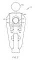
- FIG. 1schematically depicts a distractor apparatus according to one or more embodiments shown and described herein;
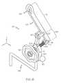
- FIG. 2schematically depicts one embodiment of a mounting body of a distractor apparatus
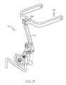
- FIG. 3schematically depicts the distractor apparatus of FIG. 1 being used to apply a distraction force to a limb of a patient;
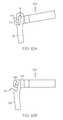
- FIG. 4schematically depicts the distractor apparatus of FIG. 3 being used to apply tension to a strap attached to the distractor apparatus;
- FIG. 5schematically depicts the distractor apparatus of FIG. 3 being used to release tension applied to a strap attached to the distractor apparatus;
- FIG. 6schematically depicts a distractor apparatus according to another embodiment shown and described herein;
- FIG. 7schematically depicts the distractor apparatus of FIG. 6 being used to apply tension to a strap attached to the distractor apparatus
- FIG. 8schematically depicts an distractor apparatus of FIG. 6 being used to release tension applied to a strap attached to the distractor apparatus
- FIG. 9schematically depicts the distractor apparatus of FIG. 6 with an accessory attached to the receiving hook of the distractor arm;
- FIGS. 10A and 10Bschematically depict the attachment of an accessory in the receiving hook of a distractor arm
- FIG. 11schematically depicts an alternative embodiment of a distractor apparatus
- FIGS. 12A-12Ischematically depict alternative embodiments of distractor apparatuses which utilize a distractor arm pivoted about a pivot point to apply tension to a limb.
- FIG. 1generally depicts one embodiment of a distractor apparatus for applying tension to a limb of a patient, such as a leg.
- the distractor apparatusgenerally comprises a mounting body, a frame, a tensioning mechanism, and a distractor arm with a receiving hook.
- the tensioning mechanism and the distractor armare pivotally coupled to the frame such that actuation of the tensioning mechanism pivots the distractor arm relative to the frame such that tension may be applied to or released from a limb coupled to the receiving hook of the distractor arm with a strap or another accessory.
- the distractor apparatus 100generally comprises a mounting body 102 , a frame 104 , a tensioning mechanism 109 and a distractor arm 122 .
- the mounting body 102is disposed on a first end of a support 126 which, in the embodiment shown in FIG. 1 , is a cylindrical rod.
- the second end of the support 126is coupled to a connector 128 with a slot 130 to facilitate coupling the distractor apparatus 100 to an accessory rail (not shown) attached to a piece of medical equipment (not shown) such as, for example, a hospital bed or operating table.
- the support 126is coupled to the connector 128 such that the support 126 is capable of rotation relative to the connector 128 .
- the frame 104 and a body yoke 118are rotatably coupled to the mounting body 102 with an axle (not shown) which extends from the frame 104 , through the mounting body 102 and into the body yoke 118 . Accordingly, it should be understood that the frame 104 and body yoke 118 are rotatable with respect to the mounting body 102 .
- the axleis integrally formed with at least one of the frame 104 or the body yoke 118 .
- the axleis a separate component which is positioned in bores (not shown) formed in the frame 104 and the body yoke 118 and secured with set screws.
- the mounting body 102may further comprise one or more bearings (not shown) through which the axle extends to facilitate rotation of the frame 104 and body yoke 118 relative to the mounting body 102 .
- Rotation of the frame 104 and body yoke 118 with respect to the mounting body 102facilitates maintaining the general orientation of the distractor apparatus 100 with respect to an attached limb (such as the leg of a patient or the like) while exerting a gross distraction force on the attached limb by rotating the support 126 with respect to the connector.
- rotation of the frame 104 and the body yoke 118 with respect to the mounting body 102controlled utilizing a set screw attached to knob 152 .
- the knob 152may be used to impinge a set screw against the axle extending through the mounting body 102 thereby preventing rotation of the frame 104 and body yoke 118 with respect to the mounting body 102 once the desired position is achieved.
- rotation of the frame 104 and the body yoke 118is controlled utilizing a keeper 160 in conjunction with grooves formed in the axle 164 .
- the keeper 160may be positioned in a slot 163 formed in the mounting body 102 with springs 166 biasing the keeper 160 into engagement with the axle 164 .
- a pair of lobes 161 , 162engage with the grooves formed in the axle 164 preventing rotation of the axle with respect to the mounting body 102 and, as such, preventing the rotation of the frame 104 and the body yoke 118 with respect to the mounting body 102 .
- the knob 152may be coupled to the keeper such that depressing the knob 152 disengages the keeper 160 from the axle 164 thereby permitting rotation of the axle 164 with respect to the mounting body 102 .
- the frame 104extends from the mounting body 102 such that the frame is generally at a right angle with respect to the support 126 .
- the frame 104is formed with at least one opening in which a pivot nut 106 is positioned.
- the pivot nut 106is disposed in the frame 104 and secured with pivot pins 112 (one shown in FIG. 1 ) such that the pivot nut 106 is free to rotate with respect to the frame 104 while being secured to the frame 104 .
- the tensioning mechanism 109generally comprises a threaded rod 108 , a control knob 110 and a rod yoke 114 .
- the threaded rod 108is threaded through the pivot nut 106 of the frame 104 such that a portion of the threaded rod 108 extends from either side of the frame.
- the control knob 110is secured to a first end of the threaded rod 108 and the rod yoke 114 is secured to the second end of the threaded rod 108 .
- the distractor arm 122is an elongated lever comprising a first portion 123 and a second portion 125 .
- the first portion 123 of the distractor arm 122is generally longer than the second portion 125 of the distractor arm 122 to increase the range of travel and the torque applied to the receiving hook 124 with the tensioning mechanism 109 .
- the receiving hook 124is formed at the free end of the first portion 123 of the distractor arm 122 to facilitate attaching one or more accessories, such as a tensioning strap, tension gauge, or the like, to the distractor arm 122 .
- the distractor arm 122is pivotally coupled to the rod yoke 114 and the body yoke 118 such that the receiving hook 124 is pivotable with respect to the mounting body 102 .
- the body yoke 118is coupled to the distractor arm 122 with pivot pin 120 such that the distractor arm 122 is pivotable about the pivot pin 120 .
- the rod yoke 114is coupled to the second portion 125 of the distractor arm 122 with pivot pin 116 .
- the first portion 123 of the distractor arm 122transitions into the second portion 125 of the distractor arm 122 proximate the pivot pin 120 coupling the distractor arm 122 to the body yoke 118 .
- the distractor arm 122is coupled to the body yoke 118 and the rod yoke 114 such that the distractor arm 122 is substantially horizontally oriented (i.e., the distractor arm is within +/ ⁇ 10 degrees from parallel with the x-y plane of the coordinate axes of FIG. 1 ). Accordingly, it should be understood that the distractor arm 122 is pivotable with respect to the mounting body 102 in the x-y plane of the coordinate axes of FIG. 1 .
- strap 150which is shown attached to the ankle of a patient in FIG. 3 and partially depicted in FIGS. 4 and 5 .
- a first portion of the strap 150is received in the receiving hook 124 of the distractor arm 122 as depicted in FIG. 3 such that a tension may be applied to the strap 150 or a tension released from the strap 150 by rotation of the distractor arm 122 about the pivot pin 120 .
- a second end (not shown) of the strap 150may be attached to a limb of a patient which is constrained either with a device or by the weight of the patient.
- the distractor apparatus 100is an ankle distractor and the strap is attached to an ankle of a patient to apply a distraction force to the leg which is counteracted by the leg being positioned in a urology leg holder.
- a distracting forcemay be applied to the strap 150 by actuating the tensioning mechanism 109 with control knob 110 .
- rotating the control knob 110 in a tensioning directioncauses the threaded rod 108 to rotate in the pivot nut thereby advancing the threaded rod 108 in the direction indicated by arrow 132 .
- the threaded rod 108advances it exerts a force on the distractor arm 122 through the rod yoke 114 .
- the force applied to the distractor arm 122causes the distractor arm 122 to rotate in a clockwise direction in the body yoke 118 about the pivot pin 120 which, in turn, causes the receiving hook 124 of the distractor arm 122 to advance in the direction generally indicated by arrow 136 , thereby applying a distraction force to the strap 150 and to the limb attached to the strap.
- FIG. 5generally depicts the threaded rod 108 and the distractor arm 122 at maximum displacement when applying a distraction force to the strap.
- the distraction force applied to the strap 150 with the distractor apparatus 100can be released by reversing the operation described above. Specifically, rotating the control knob 110 in a slack direction (which is the counter-clockwise direction indicated by arrow 138 in this example) causes the threaded rod 108 to rotate in the pivot nut thereby advancing the threaded rod 108 in the direction indicated by arrow 140 . As the threaded rod 108 advances it exerts a force on the distractor arm 122 through the rod yoke 114 .
- the force applied to the distractor arm 122causes the distractor arm 122 to rotate in a counter-clockwise direction in the body yoke 118 about the pivot pin 120 which, in turn, causes the receiving hook 124 of the distractor arm 122 to advance in the direction generally indicated by arrow 142 , thereby releasing the tension applied to the strap 150 and relaxing the distracting force to the limb attached to the strap.
- the distractor arm 122As the distractor arm 122 is rotated about the pivot pin 120 , the distractor arm 122 also rotates in the rod yoke 114 about the pivot pin 116 to accommodate for the rotation of the distractor arm in a direction which is generally opposite the direction of advance of the threaded rod 108 . Moreover, as the distractor arm 122 rotates in the counter-clockwise direction, the distractor arm exerts a torque on the threaded rod 108 causing the threaded rod 108 and the pivot nut 106 (not shown in FIG. 5 ) to rotate in the frame 104 about the pivot pin 112 in a counter-clockwise direction. The control knob 110 may be rotated in the slack direction until a sufficient amount of slack is generated in the strap 150 and/or until the threaded rod reaches the maximum extent of travel in the direction of arrow 140 .
- FIGS. 1-5generally depict one embodiment of a distractor apparatus 100
- FIG. 11depicts another embodiment of a distractor apparatus 103 in which the distractor arm 122 is substantially horizontally oriented.
- the tensioning mechanismi.e., the threaded rod 108 , control knob 110 , and pivot nut
- the support 126includes an angled extension 127 such that the mounting body 102 is cantilevered.
- the mounting body 102is rotatable on the angled extension 127 such that the horizontal orientation of the distractor arm 122 can be maintained when the support 126 is pivoted in the direction of arrow 191 or arrow 192 .
- the mounting body 102may be fixed in place on the angled extension 127 with knob 152 coupled to a set screw (not shown) once the desired orientation is achieved.
- the basic functionality of this embodiment of the distractor apparatus 103is the same as that described above with respect to the embodiment of the distractor apparatus 100 depicted in FIGS. 1-5 .
- FIGS. 1-5 and 11are described as having the distractor arm 122 substantially horizontally oriented, it should be understood that embodiments wherein the distractor arm 122 is vertically oriented are also contemplated.
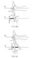
- the distractor apparatus 101in which the distractor arm 122 is substantially vertically oriented (i.e., the distractor arm is within +/ ⁇ 20 degrees of parallel with the y-z plane in the coordinate axes depicted in FIG. 7 when the control knob 110 is fully rotated in the slack direction, as shown in FIG. 7 ).
- the distractor apparatus 101generally comprises a mounting body 102 , a tensioning mechanism 109 and a distractor arm 122 .
- the mounting body 102is disposed on a first end of a support 126 which, in the embodiment shown in FIG.
- the mounting body 102is cantilevered with respect to at least a portion of the support 126 .
- the second end of the support 126may be coupled to a connector (not shown) to facilitate coupling the distractor apparatus 100 to an accessory rail (not shown) attached to a piece of medical equipment (not shown) such as, for example, a hospital bed or operating table.
- the mounting body 102is rotatably positioned on the support 126 and fixed in place with the knob 152 attached to the set screw.
- the mounting body 102is formed with at least one opening in which a pivot nut 106 is positioned.
- the pivot nut 106is disposed in the mounting body and secured with pivot pins 112 (one shown in FIG. 6 ) such that the pivot nut 106 is free to rotate with respect to the mounting body 102 about an axis which is substantially parallel with the y-axis of the coordinate axes depicted in FIG. 6 .
- the mounting body 102also includes a body yoke 118 .
- the tensioning mechanismgenerally comprises a threaded rod 108 , a control knob 110 and a rod yoke 114 .
- the threaded rod 108is threaded through the pivot nut 106 of the mounting body 102 such that a portion of the threaded rod 108 extends from either side of the mounting body.
- the control knob 110is secured to a first end of the threaded rod 108 and the rod yoke 114 is secured to the second end of the threaded rod 108 .
- the distractor arm 122is an elongated lever comprising a receiving hook 124 at a free end of the distractor arm 122 to facilitate attaching one or more accessories, such as a tensioning strap, tension gauge, or the like, to the distractor arm 122 .
- the distractor arm 122is pivotally coupled to the rod yoke 114 and the body yoke 118 such that the receiving hook 124 is pivotable with respect to the mounting body 102 .
- the body yoke 118is coupled to the distractor arm 122 with pivot pin 120 between the ends of the distractor arm such that the distractor arm 122 is pivotable about the pivot pin 120 .
- the rod yoke 114is coupled to an end of the distractor arm 122 with pivot pin 116 .
- the distractor arm 122comprises a first portion 123 which extends from the pivot pin 120 to a free end of the distractor arm 122 and a second portion 125 which generally extends between pivot pin 116 and pivot pin 120 .
- the first portion 123is generally longer than the second portion 125 to increase the range of travel of the distractor arm 122 as well as the torque applied to a strap or other accessory connected to the receiving hook 124 of the distractor arm 122 .
- the distractor arm 122is coupled to the body yoke 118 and the rod yoke 114 such that the distractor arm 122 is pivotable in the x-z plane of the coordinate axes of FIG. 6 with respect to the mounting body 102 .
- a distraction forcemay be applied to the strap 150 by actuating the tensioning mechanism with control knob 110 .
- rotating the control knob 110 in a tensioning directioncauses the threaded rod 108 to rotate in the pivot nut thereby advancing the threaded rod 108 in the direction indicated by arrow 132 .
- the threaded rod 108advances it exerts a force on the distractor arm 122 through the rod yoke 114 .
- the force applied to the distractor arm 122causes the distractor arm 122 to rotate in a counter-clockwise direction in the body yoke 118 about the pivot pin 120 which, in turn, causes the receiving hook 124 of the distractor arm 122 to advance in the direction generally indicated by arrow 136 , thereby applying a distraction force to the strap 150 and to a limb attached to the strap.
- the distractor arm 122As the distractor arm 122 is rotated about the pivot pin 120 , the distractor arm 122 also pivots in the rod yoke 114 about the pivot pin 116 to accommodate for the rotation of the distractor arm 122 . Further, as the distractor arm 122 rotates in the counter-clockwise direction, the distractor arm 122 exerts a torque on the threaded rod 108 causing the threaded rod 108 and the pivot nut 106 (not shown in FIG. 7 ) to rotate in the frame 104 about the pivot pin 112 in a counter-clockwise direction.
- FIG. 8generally depicts the threaded rod 108 and the distractor arm 122 at maximum displacement when applying a distraction force to the strap 150 .
- the distraction force applied to the strap 150 with the distractor apparatus 101can be released by reversing the operation described above. Specifically, rotating the control knob 110 in a slack direction (which is the counter-clockwise direction indicated by arrow 138 in this example) causes the threaded rod 108 to rotate in the pivot nut 106 thereby advancing the threaded rod 108 in the direction indicated by arrow 140 . As the threaded rod 108 advances it exerts a force on the distractor arm 122 through the rod yoke 114 .
- the force applied to the distractor arm 122causes the distractor arm 122 to rotate in a clockwise direction in the body yoke 118 about the pivot pin 120 which, in turn, causes the receiving hook 124 of the distractor arm 122 to advance in the direction generally indicated by arrow 142 , thereby releasing the distraction force applied to the strap 150 and relaxing the distracting force on a limb attached to the strap.
- the distractor arm 122As the distractor arm 122 is rotated about the pivot pin 120 , the distractor arm 122 also rotates in the rod yoke 114 about the pivot pin 116 to accommodate for the rotation of the distractor arm. Further, as the distractor arm 122 rotates in the clockwise direction, the distractor arm exerts a torque on the threaded rod 108 causing the threaded rod 108 and the pivot nut 106 to rotate in the mounting body 102 about the pivot pin 112 in a clockwise direction.
- the control knob 110may be rotated in the slack direction until a sufficient amount of slack is generated in the strap 150 and/or until the threaded rod reaches the maximum extent of travel in the direction of arrow 140 .
- FIGS. 9 and 10 A- 10 Bdepict the distractor arm 122 of the distraction apparatus 101 having an accessory, such as a skeletal bow 154 in this example, positioned in the receiving hook 124 .
- the skeletal bow 154may be formed with a yoke 156 having a pivot pin 158 which bisects the yoke 156 .
- the skeletal bow 154may be attached to the distractor arm 122 by positioning the free end of the distractor arm 122 in the yoke 156 of the skeletal bow 154 such that the pivot pin 158 of the yoke 156 is engaged with the receiving hook 124 thereby facilitating rotation of the skeletal bow 154 in the receiving hook 124 about the pivot pin 158 .
- the distractor apparatus 101may be utilized to exert a distraction force on the skeletal bow 154 in a similar manner as described hereinabove.
- the distraction mechanismutilizes a lever (i.e., the distractor arm) to transfer a distraction force generated along an axis of the tensioning mechanism (i.e., the tensioning axis) to a second axis (i.e., the effector axis) which is non-coaxial with the tensioning axis.
- a leveri.e., the distractor arm
- FIG. 3depicts one embodiment of the distractor apparatus 100 in which the effector axis 302 is non-coaxial with the tensioning axis 301 throughout the range of motion of the tensioning mechanism and the distractor arm 122 .
- the distractor arm 122is arranged such that the tension applied with the tensioning mechanism along the tensioning axis 301 is transferred to the effector axis 302 which is parallel (i.e., non-coaxial) with the tensioning axis 301 .
- Thisfacilitates positioning the tensioning mechanism of the distractor apparatus 100 off the long axis of the limb to which the distraction force is applied, thereby providing improved access to the limb, particularly from the area distal to the limb.
- the tensioning axis of the apparatusis substantially parallel to the effector axis throughout the range of motion of the tensioning mechanism and the distractor arm.
- FIGS. 12A-12Idepict various embodiments of distractor apparatuses in which the tensioning axis is non-coaxial with the effector axis such that the tensioning mechanism can be offset from the axis of the limb.
- FIG. 12Adepicts one embodiment of a distractor apparatus in which the tensioning apparatus has a tensioning axis 301 which is both non-parallel and non-coaxial with the effector axis 302 .
- the tensioning mechanism 109is coupled to a strut 410 which is slidably and pivotally connected to the distractor arm. Rotating the tensioning mechanism 109 advances the strut along the tensioning mechanism which, in turn, pivots the distractor arm 122 thereby providing a distraction force along the effector axis 302 .
- FIG. 12Bdepicts an embodiment of a distractor apparatus similar to that depicted in FIG. 4 , described above.
- FIG. 12Cdepicts an embodiment of a distractor apparatus in which the distractor arm 122 is pivotally coupled to a sliding block 420 .
- the tensioning mechanism 109is slidably coupled to the distractor arm with strut 411 which rides in a channel 412 of the distractor arm 122 .
- the rotation of the tensioning mechanismpushes the sliding block 420 in a direction away from the strut 411 which, in turn, causes the distractor arm 122 to slide and pivot on the strut 411 and pivot on the sliding block 420 , thereby exerting a distraction force along the effector axis 302 , which is substantially parallel with the tensioning axis 301 .
- FIG. 12Ddepicts an embodiment a distractor apparatus in which the tensioning axis 301 and the effector axis 302 are substantially parallel.
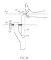
- the tensioning mechanism 109is coupled to a telescoping mechanism 440 which may be used to extend or retract the distractor arm 122 which, in this embodiment, includes a right angle bend.
- the telescoping mechanism 440may be coupled to a urology leg holder 441 .
- the tensioning mechanism 109is used to apply a distraction force along the tensioning axis 301
- the rotation of the tensioning mechanismcauses the distractor arm 122 to extend from the telescoping mechanism 440 , which translates the distraction force from the tensioning axis 301 to the effector axis 302 .
- FIGS. 12E and 12Gdepict embodiments of distractor apparatuses in which the tensioning axis 301 and the effector axis 302 are substantially parallel.
- the distractor arm 122is mounted on a support 126 and is pivotal on the support 126 about pivot point 426 .
- the distractor arm 122includes a rack 425 which engages with the tensioning mechanism 109 to pivot the distractor arm 122 about the pivot point 426 .
- the tensioning mechanism 109is rotated to apply a distraction force along the tensioning axis 301
- the distractor arm 122is rotated about the pivot point 426 such that the distraction force is translated to the effector axis 302 .
- FIG. 12Fdepicts an embodiment of a distraction apparatus in which the tensioning axis 301 and the effector axis 302 are non-coaxial and non-parallel.
- the distractor arm 122is pivotally coupled to a strut 431 which, in turn, is pivotally coupled to a free end of the support 126 .
- the distractor arm 122is also coupled to a helical gear 430 which is slidably engaged with the support 126 and engaged with the tensioning mechanism 109 .
- the tensioning mechanism 109is utilized to apply a distraction force along the tensioning axis 301 , the position of the helical gear 430 on the support 126 is adjusted, thereby rotating the distractor arm 122 relative to the support 126 such that the distraction force is translated to the effector axis 302 .
- FIG. 12Hdepicts an embodiment of a distractor apparatus in which the tensioning axis 301 and the effector axis 302 are substantially parallel.
- the distractor arm 122is pivotally mounted in a channel 412 in the support 126 such that the distractor arm 122 can slide along a length of the support 126 as well as pivot relative to the support 126 .
- the tensioning mechanism 109is also pivotally coupled to an end of the distractor arm 122 .
- the rotation of the tensioning mechanism 109pushes one end of the distractor arm 122 away from the support 126 thereby sliding the distractor arm 122 along the length of the support while simultaneously pivoting the free end of the distractor arm 122 away from the support 126 such that the distraction force is translated to the effector axis 302 .
- FIG. 12Idepicts another embodiment of a distractor apparatus in which the tensioning axis 301 and the effector axis 302 are substantially parallel.
- This embodiment of the distractor apparatusis substantially similar to the embodiment shown in FIG. 4 .
- the pivot point 450 and the tensioning mechanism 109are arranged such that the tensioning mechanism 109 is coupled to the distractor arm 122 between the pivot point 450 and the free end of the distractor arm 122 (i.e., the end comprising the receiving hook 124 ).
- distractor apparatusesfor use in applying a distraction force to a limb of a patient.
- These distractor apparatusesutilize a tensioning mechanism and lever (i.e., the distractor arm) to apply a distraction force to the limb of a patient and, as such, the mechanical advantage of the lever assists the operator in achieving the desired amount of distraction without the use of additional tools and/or apparatuses.
- the distractor apparatusesare capable of translating the distraction force from a tensioning axis to an effector axis which is non-coaxial with the tensioning axis, the distractor apparatuses may be positioned relative to a patient such that the tension mechanism does not substantially impede access to the distal areas of the limb.
Landscapes
- Health & Medical Sciences (AREA)
- Life Sciences & Earth Sciences (AREA)
- Orthopedic Medicine & Surgery (AREA)
- Animal Behavior & Ethology (AREA)
- Public Health (AREA)
- Heart & Thoracic Surgery (AREA)
- Surgery (AREA)
- Engineering & Computer Science (AREA)
- Veterinary Medicine (AREA)
- General Health & Medical Sciences (AREA)
- Biomedical Technology (AREA)
- Nursing (AREA)
- Nuclear Medicine, Radiotherapy & Molecular Imaging (AREA)
- Vascular Medicine (AREA)
- Medical Informatics (AREA)
- Molecular Biology (AREA)
- Orthopedics, Nursing, And Contraception (AREA)
Abstract
Description
Claims (18)
Priority Applications (2)
| Application Number | Priority Date | Filing Date | Title |
|---|---|---|---|
| US13/435,022US9173649B2 (en) | 2011-04-08 | 2012-03-30 | Low profile distractor apparatuses |
| EP12275037.5AEP2508153B1 (en) | 2011-04-08 | 2012-04-03 | Low profile distractor apparatuses |
Applications Claiming Priority (2)
| Application Number | Priority Date | Filing Date | Title |
|---|---|---|---|
| US201161473386P | 2011-04-08 | 2011-04-08 | |
| US13/435,022US9173649B2 (en) | 2011-04-08 | 2012-03-30 | Low profile distractor apparatuses |
Publications (2)
| Publication Number | Publication Date |
|---|---|
| US20120259343A1 US20120259343A1 (en) | 2012-10-11 |
| US9173649B2true US9173649B2 (en) | 2015-11-03 |
Family
ID=46062182
Family Applications (1)
| Application Number | Title | Priority Date | Filing Date |
|---|---|---|---|
| US13/435,022Active2033-02-23US9173649B2 (en) | 2011-04-08 | 2012-03-30 | Low profile distractor apparatuses |
Country Status (2)
| Country | Link |
|---|---|
| US (1) | US9173649B2 (en) |
| EP (1) | EP2508153B1 (en) |
Cited By (11)
| Publication number | Priority date | Publication date | Assignee | Title |
|---|---|---|---|---|
| US20140324056A1 (en)* | 2013-04-24 | 2014-10-30 | Pivot Medical, Inc. | Apparatus and method for distracting the hip joint |
| US10010473B1 (en)* | 2014-06-27 | 2018-07-03 | Charles J. Bronder, Jr. | Spinal decompression head harness and method of use |
| USD878836S1 (en) | 2017-08-17 | 2020-03-24 | Stryker Corp. | Table extender |
| US10828218B2 (en) | 2015-06-05 | 2020-11-10 | Stryker Corporation | Surgical table and accessories to facilitate hip arthroscopy |
| US10835440B2 (en) | 2016-04-01 | 2020-11-17 | Allen Medical Systems, Inc. | Boot carriage for repositioning a surgical boot along a support rod |
| US11337877B2 (en) | 2020-03-03 | 2022-05-24 | Max Salvador Azevedo | Device for applying a tensile force to a hinged joint |
| US11510805B2 (en) | 2017-02-06 | 2022-11-29 | Stryker Corp. | Anatomical gripping system for gripping the leg and foot of a patient when effecting hip distraction and/or when effecting leg positioning |
| US11559455B2 (en) | 2017-02-06 | 2023-01-24 | Stryker Corp. | Distraction frame for effecting hip distraction |
| US11564855B2 (en) | 2020-09-28 | 2023-01-31 | Stryker Corporation | Systems and methods for supporting and stabilizing a patient during hip distraction |
| US11684532B2 (en) | 2017-02-06 | 2023-06-27 | Stryker Corp. | Method and apparatus for supporting and stabilizing a patient during hip distraction |
| US11878111B2 (en) | 2020-06-24 | 2024-01-23 | Max Azevedo | Venturi inhalation device |
Families Citing this family (10)
| Publication number | Priority date | Publication date | Assignee | Title |
|---|---|---|---|---|
| GB201008281D0 (en) | 2010-05-19 | 2010-06-30 | Nikonovas Arkadijus | Indirect analysis and manipulation of objects |
| US9039706B2 (en) | 2013-03-13 | 2015-05-26 | DePuy Synthes Products, Inc. | External bone fixation device |
| CN105050517B (en) | 2013-03-13 | 2019-01-01 | 德普伊新特斯产品公司 | External bone fixation devices |
| CA2936677A1 (en)* | 2014-01-13 | 2015-07-16 | Ferno-Washington, Inc. | Accessory clamp for emergency cots |
| WO2017008087A1 (en) | 2015-07-06 | 2017-01-12 | Javier Garcia-Bengochea | Methods and devices for surgical access |
| EP3164080A4 (en) | 2014-07-06 | 2018-06-27 | Garcia-Bengochea, Javier | Methods and devices for surgical access |
| US10835318B2 (en) | 2016-08-25 | 2020-11-17 | DePuy Synthes Products, Inc. | Orthopedic fixation control and manipulation |
| US11439436B2 (en) | 2019-03-18 | 2022-09-13 | Synthes Gmbh | Orthopedic fixation strut swapping |
| US11304757B2 (en) | 2019-03-28 | 2022-04-19 | Synthes Gmbh | Orthopedic fixation control and visualization |
| US11334997B2 (en) | 2020-04-03 | 2022-05-17 | Synthes Gmbh | Hinge detection for orthopedic fixation |
Citations (57)
| Publication number | Priority date | Publication date | Assignee | Title |
|---|---|---|---|---|
| US1837037A (en)* | 1927-02-12 | 1931-12-15 | Electro Motive Instr Co | Therapeutic traction apparatus |
| US1890372A (en)* | 1931-12-03 | 1932-12-06 | Joe J Ettinger | Leg splint |
| US2198908A (en) | 1938-03-31 | 1940-04-30 | Ellis Edgar | Traction splint hitch |
| US2511182A (en) | 1948-08-25 | 1950-06-13 | Chester E Spencer | Traction hitch |
| US2644448A (en) | 1951-03-02 | 1953-07-07 | George W Jardine | Foot sling |
| US2723663A (en) | 1954-04-23 | 1955-11-15 | Ralph E Davis | Traction cuff |
| US3135257A (en) | 1961-12-01 | 1964-06-02 | Anderson Roger | Fracture tables |
| US3385292A (en) | 1965-07-23 | 1968-05-28 | James H. Hardy | Traction device |
| US3477428A (en) | 1967-06-29 | 1969-11-11 | Dyna Med Inc | Combined splint and traction device |
| US3612046A (en) | 1969-09-08 | 1971-10-12 | Medical Specialties Inc | Traction device |
| US3618598A (en) | 1969-12-08 | 1971-11-09 | Ronald H Davis | Leg traction ankle strap |
| US3680552A (en) | 1970-11-27 | 1972-08-01 | Oran M Bell | Traction splint |
| US3680551A (en) | 1970-11-27 | 1972-08-01 | Oran M Bell | Ankle hitch |
| US3720206A (en) | 1971-11-19 | 1973-03-13 | J Walker | Ankle hitch |
| US3750652A (en)* | 1971-03-05 | 1973-08-07 | J Sherwin | Knee retractor |
| US3978853A (en) | 1975-06-04 | 1976-09-07 | Morrison Medical Products Company | Ankle hitch |
| US4144880A (en) | 1977-03-11 | 1979-03-20 | Daniels E Robert | Orthopedic table |
| US4265230A (en) | 1978-07-11 | 1981-05-05 | Jordon Donald A | Traction splint |
| GB2080113A (en) | 1980-07-11 | 1982-02-03 | Hardinge Kevin | Surgical tool |
| US4350153A (en) | 1981-08-03 | 1982-09-21 | Borschneck Anthony G | Splint for use with a human leg |
| US4443005A (en) | 1982-09-09 | 1984-04-17 | Edward D. Sugarman | Foot support device |
| US4573482A (en) | 1982-07-02 | 1986-03-04 | Arthro-Medic, Inc. | Arthroscopic surgery method |
| US5020525A (en) | 1989-09-19 | 1991-06-04 | Zimmer, Inc. | Ankle distraction apparatus |
| US5025802A (en) | 1990-02-08 | 1991-06-25 | Lincoln Mills, Inc. | Surgical holding apparatus for distracting ankle |
| US5027799A (en) | 1988-04-19 | 1991-07-02 | Lincoln Mills, Inc. | Limb supporting device for arthroscopic surgery |
| US5063918A (en) | 1990-05-14 | 1991-11-12 | Guhl James F | Multi-mode distraction system for ankle arthroscopy |
| US5100129A (en) | 1990-12-28 | 1992-03-31 | Porter E Illene | Lower leg exercise device |
| US5162039A (en) | 1992-01-21 | 1992-11-10 | Dahners Laurence E | Distraction and reduction device |
| US5290220A (en) | 1992-03-16 | 1994-03-01 | Guhl James F | Non-invasive distraction system for ankle arthroscopy |
| US5608934A (en) | 1994-10-06 | 1997-03-11 | Smith & Nephew Dyonics, Inc. | Hip distractor |
| US5743898A (en) | 1995-05-12 | 1998-04-28 | Electro-Biology, Inc. | Method and apparatus for external fixation of small bones |
| US5899901A (en)* | 1991-05-18 | 1999-05-04 | Middleton; Jeffrey Keith | Spinal fixation system |
| US5967947A (en) | 1998-05-04 | 1999-10-19 | Glover; James T. | Isometric wrist exercise device |
| WO2001045601A2 (en) | 1999-12-23 | 2001-06-28 | Guhl James F | Improved clamp assembly for a non-invasive positioning device system |
| US20020128577A1 (en) | 2001-03-06 | 2002-09-12 | Smart Kenneth Thomas | Limb-positioning and traction device |
| US20040015114A1 (en) | 2002-07-22 | 2004-01-22 | Hay Michael T. | Tibial distraction device |
| US20040039397A1 (en)* | 2002-08-22 | 2004-02-26 | Helmut Weber | Medical tool |
| US6712825B2 (en)* | 1998-10-02 | 2004-03-30 | Max Aebi | Spinal disc space distractor |
| US6716218B2 (en)* | 2001-02-28 | 2004-04-06 | Hol-Med Corporation | Instrument for bone distraction and compression having ratcheting tips |
| US20060004380A1 (en)* | 2004-07-02 | 2006-01-05 | Didomenico Scott R | Compressor-distractor |
| US7097647B2 (en)* | 2003-01-25 | 2006-08-29 | Christopher Paige Segler | Tarsal joint space distractor |
| US7100296B2 (en) | 2001-01-31 | 2006-09-05 | Andrew Carl Root | Device for a foot |
| US20060224096A1 (en) | 2005-03-29 | 2006-10-05 | Matthew Lott | Splinter CR/S W |
| US7131955B2 (en) | 2004-03-05 | 2006-11-07 | Price Geoffrey M | Orthopedic traction tower system |
| US7243654B2 (en) | 2005-04-08 | 2007-07-17 | Peter Schuerch | Adjustable position limb support for surgical tables |
| US7244238B2 (en) | 2003-06-18 | 2007-07-17 | Doctor's Orders | Knee extension apparatus |
| US20070265635A1 (en) | 2005-11-30 | 2007-11-15 | Smith & Nephew, Inc. | Hip Distraction |
| US20080103425A1 (en) | 2006-10-27 | 2008-05-01 | Berlet Gregory C | Scope sock |
| US7452343B2 (en) | 2003-08-07 | 2008-11-18 | Swede-O, Inc. | Ankle support |
| US20080287995A1 (en)* | 2007-05-17 | 2008-11-20 | Gauthier Michael T | Compressor Distractor Tool |
| US7641624B2 (en) | 2006-06-09 | 2010-01-05 | Kendrick Ems, Inc. | Femur traction device |
| US20100249788A1 (en)* | 2009-03-26 | 2010-09-30 | Martin Roche | System and method for orthopedic distraction and stabilization |
| US7832401B2 (en) | 2005-11-30 | 2010-11-16 | Smith & Nephew, Inc. | Hip distraction |
| US7857780B2 (en) | 2008-09-16 | 2010-12-28 | Acumed Llc | Discretely adjustable orthopedic traction using constant-force springs |
| US20110106094A1 (en)* | 2009-10-30 | 2011-05-05 | Mitchell Robert J | Mandibular distraction system and method of use |
| US7947862B2 (en) | 2006-10-31 | 2011-05-24 | Depuy Products, Inc. | Limb stabilizing system for arthroplasty |
| US8083746B2 (en)* | 2004-05-07 | 2011-12-27 | Arthrex, Inc. | Open wedge osteotomy system and surgical method |
- 2012
- 2012-03-30USUS13/435,022patent/US9173649B2/enactiveActive
- 2012-04-03EPEP12275037.5Apatent/EP2508153B1/enactiveActive
Patent Citations (64)
| Publication number | Priority date | Publication date | Assignee | Title |
|---|---|---|---|---|
| US1837037A (en)* | 1927-02-12 | 1931-12-15 | Electro Motive Instr Co | Therapeutic traction apparatus |
| US1890372A (en)* | 1931-12-03 | 1932-12-06 | Joe J Ettinger | Leg splint |
| US2198908A (en) | 1938-03-31 | 1940-04-30 | Ellis Edgar | Traction splint hitch |
| US2511182A (en) | 1948-08-25 | 1950-06-13 | Chester E Spencer | Traction hitch |
| US2644448A (en) | 1951-03-02 | 1953-07-07 | George W Jardine | Foot sling |
| US2723663A (en) | 1954-04-23 | 1955-11-15 | Ralph E Davis | Traction cuff |
| US3135257A (en) | 1961-12-01 | 1964-06-02 | Anderson Roger | Fracture tables |
| US3385292A (en) | 1965-07-23 | 1968-05-28 | James H. Hardy | Traction device |
| US3477428A (en) | 1967-06-29 | 1969-11-11 | Dyna Med Inc | Combined splint and traction device |
| US3612046A (en) | 1969-09-08 | 1971-10-12 | Medical Specialties Inc | Traction device |
| US3618598A (en) | 1969-12-08 | 1971-11-09 | Ronald H Davis | Leg traction ankle strap |
| US3680552A (en) | 1970-11-27 | 1972-08-01 | Oran M Bell | Traction splint |
| US3680551A (en) | 1970-11-27 | 1972-08-01 | Oran M Bell | Ankle hitch |
| US3750652A (en)* | 1971-03-05 | 1973-08-07 | J Sherwin | Knee retractor |
| US3720206A (en) | 1971-11-19 | 1973-03-13 | J Walker | Ankle hitch |
| US3978853A (en) | 1975-06-04 | 1976-09-07 | Morrison Medical Products Company | Ankle hitch |
| US4144880A (en) | 1977-03-11 | 1979-03-20 | Daniels E Robert | Orthopedic table |
| US4265230A (en) | 1978-07-11 | 1981-05-05 | Jordon Donald A | Traction splint |
| GB2080113A (en) | 1980-07-11 | 1982-02-03 | Hardinge Kevin | Surgical tool |
| US4350153A (en) | 1981-08-03 | 1982-09-21 | Borschneck Anthony G | Splint for use with a human leg |
| US4573482A (en) | 1982-07-02 | 1986-03-04 | Arthro-Medic, Inc. | Arthroscopic surgery method |
| US4443005A (en) | 1982-09-09 | 1984-04-17 | Edward D. Sugarman | Foot support device |
| US5027799A (en) | 1988-04-19 | 1991-07-02 | Lincoln Mills, Inc. | Limb supporting device for arthroscopic surgery |
| US5020525A (en) | 1989-09-19 | 1991-06-04 | Zimmer, Inc. | Ankle distraction apparatus |
| US5025802A (en) | 1990-02-08 | 1991-06-25 | Lincoln Mills, Inc. | Surgical holding apparatus for distracting ankle |
| US5063918A (en) | 1990-05-14 | 1991-11-12 | Guhl James F | Multi-mode distraction system for ankle arthroscopy |
| US5100129A (en) | 1990-12-28 | 1992-03-31 | Porter E Illene | Lower leg exercise device |
| US5899901A (en)* | 1991-05-18 | 1999-05-04 | Middleton; Jeffrey Keith | Spinal fixation system |
| US5162039A (en) | 1992-01-21 | 1992-11-10 | Dahners Laurence E | Distraction and reduction device |
| US5290220A (en) | 1992-03-16 | 1994-03-01 | Guhl James F | Non-invasive distraction system for ankle arthroscopy |
| US5608934A (en) | 1994-10-06 | 1997-03-11 | Smith & Nephew Dyonics, Inc. | Hip distractor |
| US5743898A (en) | 1995-05-12 | 1998-04-28 | Electro-Biology, Inc. | Method and apparatus for external fixation of small bones |
| US5967947A (en) | 1998-05-04 | 1999-10-19 | Glover; James T. | Isometric wrist exercise device |
| US20050177173A1 (en)* | 1998-10-02 | 2005-08-11 | Max Aebi | Spinal disc space distractor |
| US6712825B2 (en)* | 1998-10-02 | 2004-03-30 | Max Aebi | Spinal disc space distractor |
| WO2001045601A2 (en) | 1999-12-23 | 2001-06-28 | Guhl James F | Improved clamp assembly for a non-invasive positioning device system |
| US7100296B2 (en) | 2001-01-31 | 2006-09-05 | Andrew Carl Root | Device for a foot |
| US6716218B2 (en)* | 2001-02-28 | 2004-04-06 | Hol-Med Corporation | Instrument for bone distraction and compression having ratcheting tips |
| US20020128577A1 (en) | 2001-03-06 | 2002-09-12 | Smart Kenneth Thomas | Limb-positioning and traction device |
| US6629944B2 (en) | 2001-03-06 | 2003-10-07 | Kenneth Thomas Smart | Limb-positioning and traction device |
| US20040167455A1 (en) | 2001-03-06 | 2004-08-26 | Smart Kenneth Thomas | Patient-receiving surgical device |
| US20040015114A1 (en) | 2002-07-22 | 2004-01-22 | Hay Michael T. | Tibial distraction device |
| US6953443B2 (en) | 2002-07-22 | 2005-10-11 | Imp Inc. | Tibial distraction device |
| US20040039397A1 (en)* | 2002-08-22 | 2004-02-26 | Helmut Weber | Medical tool |
| US7097647B2 (en)* | 2003-01-25 | 2006-08-29 | Christopher Paige Segler | Tarsal joint space distractor |
| US7244238B2 (en) | 2003-06-18 | 2007-07-17 | Doctor's Orders | Knee extension apparatus |
| US7452343B2 (en) | 2003-08-07 | 2008-11-18 | Swede-O, Inc. | Ankle support |
| US7131955B2 (en) | 2004-03-05 | 2006-11-07 | Price Geoffrey M | Orthopedic traction tower system |
| US7771378B2 (en) | 2004-03-05 | 2010-08-10 | Acumed Sports Medicine, Llc | Orthopedic traction tower system |
| US8083746B2 (en)* | 2004-05-07 | 2011-12-27 | Arthrex, Inc. | Open wedge osteotomy system and surgical method |
| US20060004380A1 (en)* | 2004-07-02 | 2006-01-05 | Didomenico Scott R | Compressor-distractor |
| US20060224096A1 (en) | 2005-03-29 | 2006-10-05 | Matthew Lott | Splinter CR/S W |
| US7243654B2 (en) | 2005-04-08 | 2007-07-17 | Peter Schuerch | Adjustable position limb support for surgical tables |
| US7947006B2 (en) | 2005-11-30 | 2011-05-24 | Smith & Nephew, Inc. | Hip distraction |
| US7832401B2 (en) | 2005-11-30 | 2010-11-16 | Smith & Nephew, Inc. | Hip distraction |
| US20110190676A1 (en) | 2005-11-30 | 2011-08-04 | Smith & Nephew, Inc. | Hip distraction |
| US20070265635A1 (en) | 2005-11-30 | 2007-11-15 | Smith & Nephew, Inc. | Hip Distraction |
| US7641624B2 (en) | 2006-06-09 | 2010-01-05 | Kendrick Ems, Inc. | Femur traction device |
| US20080103425A1 (en) | 2006-10-27 | 2008-05-01 | Berlet Gregory C | Scope sock |
| US7947862B2 (en) | 2006-10-31 | 2011-05-24 | Depuy Products, Inc. | Limb stabilizing system for arthroplasty |
| US20080287995A1 (en)* | 2007-05-17 | 2008-11-20 | Gauthier Michael T | Compressor Distractor Tool |
| US7857780B2 (en) | 2008-09-16 | 2010-12-28 | Acumed Llc | Discretely adjustable orthopedic traction using constant-force springs |
| US20100249788A1 (en)* | 2009-03-26 | 2010-09-30 | Martin Roche | System and method for orthopedic distraction and stabilization |
| US20110106094A1 (en)* | 2009-10-30 | 2011-05-05 | Mitchell Robert J | Mandibular distraction system and method of use |
Non-Patent Citations (4)
| Title |
|---|
| Arthrocare Sports Medicine, "Ankle Distraction for Arthroscopic Surgery", 2007. |
| Extended European Search Report, Aug. 13, 2012. |
| Innomed, Inc., "Shereff Ankle Distractor" and "Strap for Shereff Ankle Distractor", 2011. |
| Smith & Nephew, Inc., "Acufex® Non-Invasive Ankle Distractor", Nov. 22, 1999. |
Cited By (18)
| Publication number | Priority date | Publication date | Assignee | Title |
|---|---|---|---|---|
| US10799383B2 (en)* | 2013-04-24 | 2020-10-13 | Stryker Corporation | Apparatus and method for distracting the hip joint |
| US10022259B2 (en)* | 2013-04-24 | 2018-07-17 | Pivot Medical, Inc. | Apparatus and method for distracting the hip joint |
| US20190008673A1 (en)* | 2013-04-24 | 2019-01-10 | Pivot Medical, Inc. | Apparatus and method for distracting the hip joint |
| US20140324056A1 (en)* | 2013-04-24 | 2014-10-30 | Pivot Medical, Inc. | Apparatus and method for distracting the hip joint |
| US10010473B1 (en)* | 2014-06-27 | 2018-07-03 | Charles J. Bronder, Jr. | Spinal decompression head harness and method of use |
| US10828218B2 (en) | 2015-06-05 | 2020-11-10 | Stryker Corporation | Surgical table and accessories to facilitate hip arthroscopy |
| US12097151B2 (en) | 2015-06-05 | 2024-09-24 | Stryker Corporation | Surgical table and accessories to facilitate hip arthroscopy |
| US11382816B2 (en) | 2015-06-05 | 2022-07-12 | Stryker Corporation | Surgical table and accessories to facilitate hip arthroscopy |
| US10835440B2 (en) | 2016-04-01 | 2020-11-17 | Allen Medical Systems, Inc. | Boot carriage for repositioning a surgical boot along a support rod |
| US11826289B2 (en) | 2016-04-01 | 2023-11-28 | Allen Medical Systems, Inc. | Surgical boot with splined support rod |
| US11510805B2 (en) | 2017-02-06 | 2022-11-29 | Stryker Corp. | Anatomical gripping system for gripping the leg and foot of a patient when effecting hip distraction and/or when effecting leg positioning |
| US11559455B2 (en) | 2017-02-06 | 2023-01-24 | Stryker Corp. | Distraction frame for effecting hip distraction |
| US12303435B2 (en) | 2017-02-06 | 2025-05-20 | Stryker Corp. | Distraction frame for effecting hip distraction |
| US11684532B2 (en) | 2017-02-06 | 2023-06-27 | Stryker Corp. | Method and apparatus for supporting and stabilizing a patient during hip distraction |
| USD878836S1 (en) | 2017-08-17 | 2020-03-24 | Stryker Corp. | Table extender |
| US11337877B2 (en) | 2020-03-03 | 2022-05-24 | Max Salvador Azevedo | Device for applying a tensile force to a hinged joint |
| US11878111B2 (en) | 2020-06-24 | 2024-01-23 | Max Azevedo | Venturi inhalation device |
| US11564855B2 (en) | 2020-09-28 | 2023-01-31 | Stryker Corporation | Systems and methods for supporting and stabilizing a patient during hip distraction |
Also Published As
| Publication number | Publication date |
|---|---|
| EP2508153A1 (en) | 2012-10-10 |
| EP2508153B1 (en) | 2016-07-20 |
| US20120259343A1 (en) | 2012-10-11 |
Similar Documents
| Publication | Publication Date | Title |
|---|---|---|
| US9173649B2 (en) | Low profile distractor apparatuses | |
| US11426153B2 (en) | System and method for retracting body tissue | |
| US7314331B1 (en) | Multi-position locking mechanisms for clamping assemblies | |
| US8979858B2 (en) | External mandibular distractor with rotational clamp | |
| US7730563B1 (en) | Head support and stabilization system | |
| US8845568B2 (en) | Distractor straps for use with distractor apparatuses | |
| US8425404B2 (en) | System and method for positioning a laparoscopic device | |
| JP6464182B2 (en) | Soft tissue retractor | |
| US8216125B2 (en) | System and method for positioning a laparoscopic device | |
| US8062218B2 (en) | Surgical access instrument | |
| US9241619B2 (en) | Posterior lumbar retractor system | |
| US8932215B2 (en) | System and method for retracting body tissue | |
| JPH08504639A (en) | Surgical head clamp | |
| JP2017509389A (en) | Organizational creation | |
| JP2019520915A5 (en) | ||
| US11672549B2 (en) | Surgical jig | |
| US6716163B2 (en) | Surgical instrument holder | |
| CN109700514B (en) | Closed reduction multidirectional traction frame for tibial fracture | |
| US9693807B2 (en) | Spinal compressor and distractor | |
| AU2010217947A1 (en) | Surgical access instrument | |
| WO2010087360A1 (en) | Extensible holding arm device | |
| CN117503306A (en) | External fixing support | |
| CN210355272U (en) | a surgical tool | |
| EP3076887A1 (en) | Device for tensioning apparatus for fusion, stabilization, and/or fixation of bones | |
| CN210872030U (en) | Minimally invasive surgery robot with horizontal telescopic joint |
Legal Events
| Date | Code | Title | Description |
|---|---|---|---|
| AS | Assignment | Owner name:ALLEN MEDICAL SYSTEMS, INC., INDIANA Free format text:ASSIGNMENT OF ASSIGNORS INTEREST;ASSIGNORS:CLARK, ANDREW;CHELLA, DAVID;DRAKE, JESSE;REEL/FRAME:027977/0307 Effective date:20120329 | |
| AS | Assignment | Owner name:JPMORGAN CHASE BANK, N.A., AS COLLATERAL AGENT, ILLINOIS Free format text:SECURITY INTEREST;ASSIGNORS:ALLEN MEDICAL SYSTEMS, INC.;HILL-ROM SERVICES, INC.;ASPEN SURGICAL PRODUCTS, INC.;AND OTHERS;REEL/FRAME:036582/0123 Effective date:20150908 Owner name:JPMORGAN CHASE BANK, N.A., AS COLLATERAL AGENT, IL Free format text:SECURITY INTEREST;ASSIGNORS:ALLEN MEDICAL SYSTEMS, INC.;HILL-ROM SERVICES, INC.;ASPEN SURGICAL PRODUCTS, INC.;AND OTHERS;REEL/FRAME:036582/0123 Effective date:20150908 | |
| STCF | Information on status: patent grant | Free format text:PATENTED CASE | |
| AS | Assignment | Owner name:JPMORGAN CHASE BANK, N.A., AS COLLATERAL AGENT, ILLINOIS Free format text:SECURITY AGREEMENT;ASSIGNORS:HILL-ROM SERVICES, INC.;ASPEN SURGICAL PRODUCTS, INC.;ALLEN MEDICAL SYSTEMS, INC.;AND OTHERS;REEL/FRAME:040145/0445 Effective date:20160921 Owner name:JPMORGAN CHASE BANK, N.A., AS COLLATERAL AGENT, IL Free format text:SECURITY AGREEMENT;ASSIGNORS:HILL-ROM SERVICES, INC.;ASPEN SURGICAL PRODUCTS, INC.;ALLEN MEDICAL SYSTEMS, INC.;AND OTHERS;REEL/FRAME:040145/0445 Effective date:20160921 | |
| MAFP | Maintenance fee payment | Free format text:PAYMENT OF MAINTENANCE FEE, 4TH YEAR, LARGE ENTITY (ORIGINAL EVENT CODE: M1551); ENTITY STATUS OF PATENT OWNER: LARGE ENTITY Year of fee payment:4 | |
| AS | Assignment | Owner name:ANODYNE MEDICAL DEVICE, INC., FLORIDA Free format text:RELEASE BY SECURED PARTY;ASSIGNOR:JPMORGAN CHASE BANK, N.A.;REEL/FRAME:050254/0513 Effective date:20190830 Owner name:MORTARA INSTRUMENT, INC., WISCONSIN Free format text:RELEASE BY SECURED PARTY;ASSIGNOR:JPMORGAN CHASE BANK, N.A.;REEL/FRAME:050254/0513 Effective date:20190830 Owner name:MORTARA INSTRUMENT SERVICES, INC., WISCONSIN Free format text:RELEASE BY SECURED PARTY;ASSIGNOR:JPMORGAN CHASE BANK, N.A.;REEL/FRAME:050254/0513 Effective date:20190830 Owner name:HILL-ROM, INC., ILLINOIS Free format text:RELEASE BY SECURED PARTY;ASSIGNOR:JPMORGAN CHASE BANK, N.A.;REEL/FRAME:050254/0513 Effective date:20190830 Owner name:ALLEN MEDICAL SYSTEMS, INC., ILLINOIS Free format text:RELEASE BY SECURED PARTY;ASSIGNOR:JPMORGAN CHASE BANK, N.A.;REEL/FRAME:050254/0513 Effective date:20190830 Owner name:HILL-ROM COMPANY, INC., ILLINOIS Free format text:RELEASE BY SECURED PARTY;ASSIGNOR:JPMORGAN CHASE BANK, N.A.;REEL/FRAME:050254/0513 Effective date:20190830 Owner name:VOALTE, INC., FLORIDA Free format text:RELEASE BY SECURED PARTY;ASSIGNOR:JPMORGAN CHASE BANK, N.A.;REEL/FRAME:050254/0513 Effective date:20190830 Owner name:WELCH ALLYN, INC., NEW YORK Free format text:RELEASE BY SECURED PARTY;ASSIGNOR:JPMORGAN CHASE BANK, N.A.;REEL/FRAME:050254/0513 Effective date:20190830 Owner name:HILL-ROM SERVICES, INC., ILLINOIS Free format text:RELEASE BY SECURED PARTY;ASSIGNOR:JPMORGAN CHASE BANK, N.A.;REEL/FRAME:050254/0513 Effective date:20190830 | |
| AS | Assignment | Owner name:JPMORGAN CHASE BANK, N.A., ILLINOIS Free format text:SECURITY AGREEMENT;ASSIGNORS:HILL-ROM HOLDINGS, INC.;HILL-ROM, INC.;HILL-ROM SERVICES, INC.;AND OTHERS;REEL/FRAME:050260/0644 Effective date:20190830 | |
| AS | Assignment | Owner name:HILL-ROM HOLDINGS, INC., ILLINOIS Free format text:RELEASE OF SECURITY INTEREST AT REEL/FRAME 050260/0644;ASSIGNOR:JPMORGAN CHASE BANK, N.A.;REEL/FRAME:058517/0001 Effective date:20211213 Owner name:BARDY DIAGNOSTICS, INC., ILLINOIS Free format text:RELEASE OF SECURITY INTEREST AT REEL/FRAME 050260/0644;ASSIGNOR:JPMORGAN CHASE BANK, N.A.;REEL/FRAME:058517/0001 Effective date:20211213 Owner name:VOALTE, INC., FLORIDA Free format text:RELEASE OF SECURITY INTEREST AT REEL/FRAME 050260/0644;ASSIGNOR:JPMORGAN CHASE BANK, N.A.;REEL/FRAME:058517/0001 Effective date:20211213 Owner name:HILL-ROM, INC., ILLINOIS Free format text:RELEASE OF SECURITY INTEREST AT REEL/FRAME 050260/0644;ASSIGNOR:JPMORGAN CHASE BANK, N.A.;REEL/FRAME:058517/0001 Effective date:20211213 Owner name:WELCH ALLYN, INC., NEW YORK Free format text:RELEASE OF SECURITY INTEREST AT REEL/FRAME 050260/0644;ASSIGNOR:JPMORGAN CHASE BANK, N.A.;REEL/FRAME:058517/0001 Effective date:20211213 Owner name:ALLEN MEDICAL SYSTEMS, INC., ILLINOIS Free format text:RELEASE OF SECURITY INTEREST AT REEL/FRAME 050260/0644;ASSIGNOR:JPMORGAN CHASE BANK, N.A.;REEL/FRAME:058517/0001 Effective date:20211213 Owner name:HILL-ROM SERVICES, INC., ILLINOIS Free format text:RELEASE OF SECURITY INTEREST AT REEL/FRAME 050260/0644;ASSIGNOR:JPMORGAN CHASE BANK, N.A.;REEL/FRAME:058517/0001 Effective date:20211213 Owner name:BREATHE TECHNOLOGIES, INC., CALIFORNIA Free format text:RELEASE OF SECURITY INTEREST AT REEL/FRAME 050260/0644;ASSIGNOR:JPMORGAN CHASE BANK, N.A.;REEL/FRAME:058517/0001 Effective date:20211213 | |
| MAFP | Maintenance fee payment | Free format text:PAYMENT OF MAINTENANCE FEE, 8TH YEAR, LARGE ENTITY (ORIGINAL EVENT CODE: M1552); ENTITY STATUS OF PATENT OWNER: LARGE ENTITY Year of fee payment:8 |