US9173623B2 - X-ray tube and receiver inside mouth - Google Patents
X-ray tube and receiver inside mouthDownload PDFInfo
- Publication number
- US9173623B2 US9173623B2US14/249,186US201414249186AUS9173623B2US 9173623 B2US9173623 B2US 9173623B2US 201414249186 AUS201414249186 AUS 201414249186AUS 9173623 B2US9173623 B2US 9173623B2
- Authority
- US
- United States
- Prior art keywords
- source
- ray
- tooth
- receiver
- patient
- Prior art date
- Legal status (The legal status is an assumption and is not a legal conclusion. Google has not performed a legal analysis and makes no representation as to the accuracy of the status listed.)
- Expired - Fee Related, expires
Links
- 238000000034methodMethods0.000claimsabstractdescription38
- 230000005855radiationEffects0.000claimsabstractdescription7
- 238000004846x-ray emissionMethods0.000claimsdescription9
- 206010073306Exposure to radiationDiseases0.000description9
- 241001465754MetazoaSpecies0.000description3
- 230000005540biological transmissionEffects0.000description3
- 210000001519tissueAnatomy0.000description3
- 230000004907fluxEffects0.000description2
- 230000005802health problemEffects0.000description2
- 239000013077target materialSubstances0.000description2
- 210000000988bone and boneAnatomy0.000description1
- 239000000463materialSubstances0.000description1
- 230000003239periodontal effectEffects0.000description1
Images


Classifications
- A—HUMAN NECESSITIES
- A61—MEDICAL OR VETERINARY SCIENCE; HYGIENE
- A61B—DIAGNOSIS; SURGERY; IDENTIFICATION
- A61B6/00—Apparatus or devices for radiation diagnosis; Apparatus or devices for radiation diagnosis combined with radiation therapy equipment
- A61B6/50—Apparatus or devices for radiation diagnosis; Apparatus or devices for radiation diagnosis combined with radiation therapy equipment specially adapted for specific body parts; specially adapted for specific clinical applications
- A61B6/51—Apparatus or devices for radiation diagnosis; Apparatus or devices for radiation diagnosis combined with radiation therapy equipment specially adapted for specific body parts; specially adapted for specific clinical applications for dentistry
- A61B6/512—Intraoral means
- A61B6/145—
- A—HUMAN NECESSITIES
- A61—MEDICAL OR VETERINARY SCIENCE; HYGIENE
- A61B—DIAGNOSIS; SURGERY; IDENTIFICATION
- A61B6/00—Apparatus or devices for radiation diagnosis; Apparatus or devices for radiation diagnosis combined with radiation therapy equipment
- A61B6/40—Arrangements for generating radiation specially adapted for radiation diagnosis
- A61B6/4057—Arrangements for generating radiation specially adapted for radiation diagnosis by using radiation sources located in the interior of the body
- A—HUMAN NECESSITIES
- A61—MEDICAL OR VETERINARY SCIENCE; HYGIENE
- A61B—DIAGNOSIS; SURGERY; IDENTIFICATION
- A61B6/00—Apparatus or devices for radiation diagnosis; Apparatus or devices for radiation diagnosis combined with radiation therapy equipment
- A61B6/42—Arrangements for detecting radiation specially adapted for radiation diagnosis
- A61B6/4208—Arrangements for detecting radiation specially adapted for radiation diagnosis characterised by using a particular type of detector
- A61B6/425—Arrangements for detecting radiation specially adapted for radiation diagnosis characterised by using a particular type of detector using detectors specially adapted to be used in the interior of the body
- A—HUMAN NECESSITIES
- A61—MEDICAL OR VETERINARY SCIENCE; HYGIENE
- A61B—DIAGNOSIS; SURGERY; IDENTIFICATION
- A61B6/00—Apparatus or devices for radiation diagnosis; Apparatus or devices for radiation diagnosis combined with radiation therapy equipment
- A61B6/54—Control of apparatus or devices for radiation diagnosis
- A61B6/542—Control of apparatus or devices for radiation diagnosis involving control of exposure
Definitions
- the present applicationis related generally to dental x-rays.
- Typical dental x-raysare performed with an x-ray source or an x-ray receiver disposed outside the mouth of a patient, and the other of the x-ray source or x-ray receiver disposed inside the mouth of the patient.
- the patient's cheek or lipmay force a gap between source or receiver and the tooth. Because of this gap, increased x-ray flux may be needed to obtain an image of the tooth.
- the cheek or lipmay also block the medical professional's view, resulting in images taken at incorrect locations. As a result, the x-ray image may need to be retaken. Increased x-ray flux due to the large gap and due to retakes of the image may expose the patient to extra, undesirable radiation, which can cause health problems. For example, see Korean Patent Number KR 10-1147059 and U.S. Pat. Nos. 3,752,990, 3,906,235, 4,100,417, 4,193,002.
- the present inventionis directed to a method and a device that satisfies these needs.
- the device for dental x-rayscan comprise an x-ray source sized and configured to have at least an x-ray emission portion of the x-ray source disposed in a patient's mouth and an x-ray receiver sized and configured to have at least an x-ray image receiving portion of the x-ray receiver disposed in the patient's mouth.
- a bite holdercan be attached to the x-ray source and to the x-ray receiver such that an x-ray emission window of the x-ray source faces the x-ray image receiving portion of the x-ray receiver.
- the gapcan be sized and configured to extend across a tooth in the patient's mouth and to hold the x-ray source on one side of the tooth and the x-ray receiver on an opposite side of the patient's tooth.
- the method, of taking x-rays of a patient's toothcan comprise:
- FIG. 1is a schematic view of a dental x-ray device 10 , or method of taking dental x-rays, including at least a portion of an x-ray source 13 disposed between a tongue 17 and a tooth 16 of the patient and at least a portion of a receiver 11 disposed between a cheek or lip 15 and a tooth 16 of the patient, in accordance with an embodiment of the present invention;
- FIG. 2is a schematic view of a dental x-ray device 20 , or method of taking dental x-rays, including at least a portion of a receiver 11 disposed between a tongue 17 and a tooth 16 of the patient, and at least a portion of a x-ray source 13 disposed between a cheek or lip 15 and a tooth 16 of the patient, in accordance with an embodiment of the present invention;
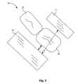
- FIG. 3is a schematic view of a dental x-ray device 30 , or method of taking dental x-rays, including at least a portion of a receiver 11 and at least a portion of an x-ray source 13 disposed inside a mouth of a patient and showing a distance D 1 between a tooth 16 and the x-ray source 13 and a distance D 2 between the receiver 11 and the x-ray source 13 , in accordance with an embodiment of the present invention;
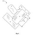
- FIG. 4is a schematic view of a dental x-ray device 40 , or method of taking dental x-rays, including at least a portion of a receiver 11 and at least a portion of an x-ray source 13 disposed inside a mouth of a patient with a bite holder 41 extending across a biting surface 16 b of the tooth 16 and holding the source 13 in position on one side of the tooth 16 and the receiver 11 in position on an opposite side of the tooth 16 , in accordance with an embodiment of the present invention;
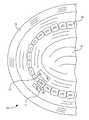
- FIG. 5is a schematic view of a dental x-ray device 50 , or method of taking dental x-rays, for taking dental x-rays of multiple teeth 16 at one time, in accordance with an embodiment of the present invention
- FIG. 6is a schematic cross-sectional side view of a dental, side-window x-ray tube 23 firmly mounted to a battery power supply 18 , in accordance with an embodiment of the present invention
- the power supply 18can be as shown in FIGS. 2 , 5 and 7 .
- FIG. 7is a schematic cross-sectional side view of a dental, side-window x-ray tube 23 connected to a power supply 18 by a flexible cable 14 , in accordance with an embodiment of the present invention
- FIG. 8is a schematic cross-sectional side view of a transmission or end window, dental x-ray tube 23 , in accordance with an embodiment of the present invention.
- FIG. 9is a schematic view of a dental x-ray device 90 , or method of taking dental x-rays, in accordance with an embodiment of the present invention.
- toothincludes a single tooth or multiple teeth.
- teethincludes not only the tooth itself but also surrounding periodontal tissues and alveolar bone.
- x-ray devices 10 , 20 , 30 , 40 , 50 , and 90 for dental x-rayscomprising an x-ray source 13 and an x-ray receiver 11 .
- the source 13 and the receiver 11can be sized and configured to be disposed at least partially in a patient's mouth. Configured to be disposed in a patient's mouth means that these units 11 and 13 are shaped and made of materials that will fit properly in the patient's mouth, are designed for patient comfort, and will result in optimal safety for the patient.
- At least a portion of the source 13can be disposed between a tongue 17 of a patient and a tooth 16 .
- At least a portion of the receiver 11can be disposed between a cheek or lip 15 of the patient and the tooth 16 .
- At least a portion of the receiver 11can be disposed between a tongue 17 of a patient and a tooth 16 .
- At least a portion of the source 13can be disposed between a cheek or lip 15 of the patient and the tooth 16 .
- X-rays 12can be emitted from the source 13 through the tooth 16 to the receiver 11 .
- the relative position of the source 13 and the receiver 11may depend on manufacturability considerations of these devices, patient comfort, and space in the patient's mouth.
- the source 13can include a power supply 18 and an x-ray tube 23 .
- the power supply 18can be firmly mounted to the x-ray tube 23 as shown in FIGS. 6 , 8 , and 9 .
- the power supply 18can be connected to the x-ray tube 23 by a flexible cable 14 as shown in FIGS. 2 , 5 and 7 .
- the entire x-ray tube 23can be disposed inside the mouth of the patient.
- the portion of the x-ray source 13 inside the mouth of the patientcan include an x-ray emission portion of the x-ray source 13 .
- an x-ray window 42 of the x-ray tube 23(see FIGS. 6-8 ) or optics attached to an end of the x-ray tube (not shown in the figures) can be disposed inside the mouth.
- An x-ray tube anode 63can also be disposed inside the mouth.
- the cathode 61can be disposed outside of the mouth.
- the power supply 18can be disposed outside of the mouth.
- the receiver 11can be a photographic film configured to record an image of x-ray exposure on the film.
- the receiver 11can be an electronic x-ray sensor or detector electrically connected to an external device for creating an image of the tooth 16 .
- All or a portion of the receiver 11can be disposed inside the mouth of the patient.
- the portion of the x-ray receiver 11 inside the mouth of the patientcan include an x-ray image receiving portion 51 (see FIG. 5 ).
- the x-ray image receiving portion 51can be an electronic sensor or detector which can be disposed partially or entirely in the mouth.
- the x-ray image receiving portion 51can be electrically connected (e.g. see cable 52 in FIG. 5 ) to associated electronic equipment 53 which can be disposed outside of the mouth.
- the source 13can be configured to direct x-rays 12 primarily at the tooth 16 and to block x-rays 12 from being emitted in other directions, such as with appropriately placed shielding.
- a side window x-ray tubecan naturally provide some of this shielding.
- both the source 13 and the receiver 11 unitsBy disposing both the source 13 and the receiver 11 units at least partially in the mouth of the patient while doing the dental x-ray, multiple advantages can be realized. First, by disposing these units 11 and 13 adjacent to the tooth 16 , it is easier to irradiate the correct area, thus reducing retakes of the x-ray image. Second, by disposing these units 11 and 13 adjacent to the tooth 16 , less radiation is required to obtain a desired image than would otherwise be the case if one of these devices 11 or 13 was disposed outside the mouth. Reduced radiation can result in reduced health problems caused by x-ray radiation. Third, due to reduced required radiation, the source 13 can be powered by a portable power supply 18 .
- Reduced patient radiation exposurecan be quantified by an amount of electrical current 62 between a cathode 61 and an anode 63 of the source 13 for recording an image of the tooth 16 (anode and cathode are shown in FIGS. 6-8 ).
- the electrical current 62 to record a single image of a tooth 16can be less than 0.1 milliamps in one embodiment, less than 1 milliamp in another embodiment, less than 3 milliamps in another embodiment, or between 0.01 and 1 milliamp in another embodiment.
- Reduced patient radiation exposurecan be quantified by patient radiation exposure in micro sieverts ( ⁇ Sv).
- ⁇ Svmicro sieverts
- This exposurecan result from taking an image of a single tooth 16 .
- patient radiation exposure to record a single image of a toothcan be less than 2 micro sieverts ( ⁇ Sv) in one embodiment, less than 1 ⁇ Sv in another embodiment, less than 0.3 ⁇ Sv in another embodiment, or less than 0.15 ⁇ Sv in another embodiment.
- This exposurecan result from recording a full mouth series of x-rays of all of the patient's teeth and adjacent hard tissue (FMX).
- patient radiation exposure for FMXcan be less than 15 micro sieverts ( ⁇ Sv), less than 5 ⁇ Sv, or less than 2.5 ⁇ Sv.
- x-ray device 30Shown in FIG. 3 is x-ray device 30 , which is an expanded view of x-ray devices 10 or 20 , in order to show a more detailed view.
- a distance D 1 between the source 13 and the tooth 16 , and a distance D 2 between the source 13 and the receiver 11can be small in order to help ensure the image is taken in the correct location and to minimize patient radiation exposure in taking the image.
- the distance D 1 between the source 13 and the tooth 16can be less than 5 mm in one embodiment, less than 10 mm in another embodiment, less than 15 mm in another embodiment, between 1 mm and 5 mm in another embodiment, or between 1 mm and 15 mm in another embodiment.
- the distance D 2 between the source 13 and the receiver 11can be less than less than 20 mm in one embodiment, less than 40 mm in another embodiment, or between 10 mm and 40 mm in another embodiment. In one embodiment, the distance D 2 between the source 13 and the receiver 11 may be at a minimum when the distance D 2 is approximately the width of the tooth 16 and may be at a maximum when the source 13 and the receiver 11 are pressed against a cheek or lip and/or against a tongue, respectively.
- a bite holder 41can be attached to the source 13 and to the receiver 11 .
- the bite holder 41can extend across a biting surface 16 b of the tooth 16 and can hold the source 13 in position on one side of the tooth 16 and the receiver 11 in position on an opposite side of the tooth 16 .
- An x-ray emission window 42 of the source 13can face a portion 43 of the receiver 11 configured to receive the x-rays 12 .
- a gap G on the bite holder 41 between the source 13 and the receiver 11can be sized and configured to extend across a tooth in the patient's mouth to hold the source 13 on one side of the tooth 16 and the receiver 11 on an opposite side of the patient's tooth 16 .
- the bite holder 41can be configured to hold the source 13 between the tooth 16 and the cheek or lip 15 and to hold the receiver 11 on an opposite side of the tooth 16 between the tongue 17 and the tooth 16 .
- the bite holder 41can be configured to hold the receiver 11 between the tooth 16 and the cheek or lip 15 and to hold the source 13 on an opposite side of the tooth 16 between the tongue 17 and the tooth 16 .
- the bite holder 41can be configured for either position, that is to hold either the receiver 11 or the source 13 between the tooth 16 and the cheek or lip 15 and to hold the other of the receiver 11 or the source 13 on an opposite side of the tooth 16 between the tongue 17 and the tooth 16 .
- the gapcan be sized and configured to extend across an adult human's tooth, a human child's tooth, or the tooth of an animal.
- the gapmay be adjustable by adjusting a position of the receiver 11 or the source 13 on the bite holder 41 to accommodate teeth 16 or mouths of different sizes.
- the bite holder 41may hold the source 13 and the receiver 11 in position about the tooth 16 when the patient “bites” the bite holder, or applies a pressure to the bite holder 41 using a tooth opposite the tooth 16 receiving the x-rays 12 .
- the term “tooth” 16 as mentioned hereincan include multiple teeth and the device can be configured to emit x-rays 12 through and to record an image of multiple teeth at one time.
- the devicecan be configured to emit x-rays 12 through and to record an image of a single tooth 16 at one time.
- FIG. 5illustrates images of two teeth being recorded at one time, the x-ray device 50 may be configured to record images more than two teeth at one time.
- the x-ray tube 23can be or can include a side window x-ray tube. Electrons in an electrical current 62 can be emitted from a cathode 61 and can strike an anode 63 .
- the anode 63can include a target material configured to produce x-rays 12 in response to impinging electrons.
- the anodecan at least partially face a window 42 and can emit x-rays 12 through an interior of the x-ray tube 23 and out through the window 42 .
- the x-ray tube 23can be a transmission or end window type. Electrons in an electrical current 62 can be emitted from a cathode 61 and can strike a window 42 portion of the anode 63 .
- the window 42can include a target material configured to produce x-rays 12 in response to impinging electrons. Manufacturability, patient comfort, and whether the teeth 16 examined are at a front or back of the mouth may be considered in deciding between a side window or end window x-ray source.
- the x-ray source 13can include an x-ray tube 23 with a battery-operated power supply 18 firmly mounted at one end of the tube 23 (e.g. the cathode 61 end).
- the x-ray source 13can include an x-ray tube 23 powered by a power supply 18 that is attached to the x-ray tube 23 only by a flexible cable 14 (not firmly mounted to the x-ray tube 23 ).
- the power supply 18can be electrical power from a wall outlet or can be a battery and can transmit electrical power through an electrical cable 14 .
- the source 13can be a battery-powered, portable power supply 18 .
- the power of the x-ray tube and the voltage between the cathode 61 and the anode 63can be relatively small.
- the power supply 18can be configured to provide a bias voltage between the anode 63 and the cathode 61 of less than 51 kilovolts in one embodiment.
- a method of taking x-rays of a patient's toothcan comprise:
- the source 13 in the methodcan include an x-ray tube 23 and an electrical power supply 18 .
- the power supplycan be attached to the x-ray tube 23 only by a flexible cable 14 or can be firmly mounted to the x-ray tube 23 .
- the source 13 in the methodcan be between the tooth 16 and the cheek or lip 15 and the receiver 11 can be on an opposite side of the tooth 16 between a tongue 17 of the mouth and the tooth 16 .
- the receiver 11 in the methodcan be between the tooth 16 and the cheek or lip 15 and the source 13 can be on an opposite side of the tooth 16 between a tongue 17 of the mouth and the tooth 16 .
- the receiver 11 in the methodcan be a photographic film configured to record an image of x-ray exposure on the film.
- the receiver 11 in the methodcan be an electronic x-ray sensor or detector electrically connected to an external device for creating an image of the tooth 16 .
- the tooth 16 in the methodcan include multiple teeth and the receiver 11 can record an image of multiple teeth at one time.
- the tooth 16 in the methodcan include a single tooth 16 and the receiver 11 can record an image of a single tooth 16 at one time.
- the source 13 in the methodcan be a side window or transmission end window x-ray tube 23 .
- the source 13 in the methodcan be configured to direct x-rays 12 primarily at the tooth 16 and to block x-rays 12 from being emitted in other directions.
- a voltage between an anode and a cathode of the source 13can be less than 51 kilovolts.
- a distance in the method between the source 13 and the tooth 16can be less than 5 mm.
- a distance between the source 13 and the receiver 11can be less than 20 mm.
- An electrical current in the method, between a cathode and an anode of the source 13 , to record a single image of the tooth 16can be less than 1 milliamp.
- Patient radiation exposure in the method to record a single image of the tooth 16can be less than 1 micro sievert ( ⁇ Sv).
- Radiation exposure in the method of the patientcan be less than 15 micro sieverts ( ⁇ Sv) for a full mouth series of x-rays 12 of all of the patient's teeth and adjacent hard tissue (FMX).
- the source 13 and the receiver 11 in the methodcan be supported by, and attached to each other by, a bite holder.
- the bite holdercan extend across a biting surface of the tooth 16 and can hold the source 13 in position on one side of the tooth 16 and the receiver 11 in position on an opposite side of the tooth 16 while x-rays 12 are emitted through the tooth 16 and received by the receiver 11 .
- the patient in the methodcan be human, can be animal, or can be a model, such as of a tooth of human or animal.
Landscapes
- Health & Medical Sciences (AREA)
- Life Sciences & Earth Sciences (AREA)
- Medical Informatics (AREA)
- Engineering & Computer Science (AREA)
- Radiology & Medical Imaging (AREA)
- Molecular Biology (AREA)
- Biophysics (AREA)
- Nuclear Medicine, Radiotherapy & Molecular Imaging (AREA)
- Optics & Photonics (AREA)
- Pathology (AREA)
- Physics & Mathematics (AREA)
- Biomedical Technology (AREA)
- Heart & Thoracic Surgery (AREA)
- High Energy & Nuclear Physics (AREA)
- Surgery (AREA)
- Animal Behavior & Ethology (AREA)
- General Health & Medical Sciences (AREA)
- Public Health (AREA)
- Veterinary Medicine (AREA)
- Dentistry (AREA)
- Oral & Maxillofacial Surgery (AREA)
- Apparatus For Radiation Diagnosis (AREA)
Abstract
Description
- 1. placing an x-ray emission portion of an x-ray source on one side of the tooth inside of a mouth of the patient and an x-ray image receiving portion of an x-ray receiver on an opposite side of the tooth inside the mouth, wherein:
- a. the source or the receiver is between a cheek or lip of the mouth and the tooth; and
- b. the other of the source or the receiver is on an opposite side of the tooth; and
- 2. emitting x-rays from the source through the tooth and onto the receiver.
- 1. placing an x-ray emission portion of a
source 13 on one side of thetooth 16 inside of a mouth of the patient and an x-ray image receiving portion of anx-ray receiver 11 on an opposite side of thetooth 16 inside the mouth, wherein:- a. the
source 13 or thereceiver 11 is between a cheek orlip 15 of the mouth and thetooth 16; and - b. the other of the
source 13 or thereceiver 11 is on an opposite side of thetooth 16; and
- a. the
- 2. emitting
x-rays 12 from thesource 13 through thetooth 16 and onto thereceiver 11.
Claims (20)
Priority Applications (1)
| Application Number | Priority Date | Filing Date | Title |
|---|---|---|---|
| US14/249,186US9173623B2 (en) | 2013-04-19 | 2014-04-09 | X-ray tube and receiver inside mouth |
Applications Claiming Priority (2)
| Application Number | Priority Date | Filing Date | Title |
|---|---|---|---|
| US201361814144P | 2013-04-19 | 2013-04-19 | |
| US14/249,186US9173623B2 (en) | 2013-04-19 | 2014-04-09 | X-ray tube and receiver inside mouth |
Publications (2)
| Publication Number | Publication Date |
|---|---|
| US20140341346A1 US20140341346A1 (en) | 2014-11-20 |
| US9173623B2true US9173623B2 (en) | 2015-11-03 |
Family
ID=51895785
Family Applications (1)
| Application Number | Title | Priority Date | Filing Date |
|---|---|---|---|
| US14/249,186Expired - Fee RelatedUS9173623B2 (en) | 2013-04-19 | 2014-04-09 | X-ray tube and receiver inside mouth |
Country Status (1)
| Country | Link |
|---|---|
| US (1) | US9173623B2 (en) |
Cited By (1)
| Publication number | Priority date | Publication date | Assignee | Title |
|---|---|---|---|---|
| US20220399196A1 (en)* | 2019-11-11 | 2022-12-15 | Ametek Finland Oy | A shield device for a radiation window, a radiation arrangement comprising the shield device, and a method for producing the shield device |
Families Citing this family (1)
| Publication number | Priority date | Publication date | Assignee | Title |
|---|---|---|---|---|
| KR101684781B1 (en)* | 2015-05-11 | 2016-12-08 | 고려대학교 산학협력단 | X-ray imaging apparatus for minimally invasive surgery |
Citations (286)
| Publication number | Priority date | Publication date | Assignee | Title |
|---|---|---|---|---|
| US1276706A (en) | 1918-04-30 | 1918-08-27 | Gurdy L Aydelotte | Land-torpedo. |
| US1881448A (en) | 1928-08-15 | 1932-10-11 | Formell Corp Ltd | X-ray method and means |
| US1946288A (en) | 1929-09-19 | 1934-02-06 | Gen Electric | Electron discharge device |
| US2291948A (en) | 1940-06-27 | 1942-08-04 | Westinghouse Electric & Mfg Co | High voltage X-ray tube shield |
| US2316214A (en) | 1940-09-10 | 1943-04-13 | Gen Electric X Ray Corp | Control of electron flow |
| US2329318A (en) | 1941-09-08 | 1943-09-14 | Gen Electric X Ray Corp | X-ray generator |
| US2340363A (en) | 1942-03-03 | 1944-02-01 | Gen Electric X Ray Corp | Control for focal spot in X-ray generators |
| US2502070A (en) | 1949-01-19 | 1950-03-28 | Dunlee Corp | Getter for induction flashing |
| US2663812A (en) | 1950-03-04 | 1953-12-22 | Philips Lab Inc | X-ray tube window |
| US2683223A (en) | 1952-07-24 | 1954-07-06 | Licentia Gmbh | X-ray tube |
| DE1030936B (en) | 1952-01-11 | 1958-05-29 | Licentia Gmbh | Vacuum-tight radiation window made of beryllium for discharge vessels |
| US2952790A (en) | 1957-07-15 | 1960-09-13 | Raytheon Co | X-ray tubes |
| US3356559A (en) | 1963-07-01 | 1967-12-05 | University Patents Inc | Colored fiber metal structures and method of making the same |
| US3358368A (en) | 1966-03-08 | 1967-12-19 | Eversharp Inc | Adjustable double edge razor |
| US3397337A (en) | 1966-01-14 | 1968-08-13 | Ion Physics Corp | Flash X-ray dielectric wall structure |
| US3434062A (en) | 1965-06-21 | 1969-03-18 | James R Cox | Drift detector |
| GB1252290A (en) | 1967-12-28 | 1971-11-03 | ||
| US3665236A (en) | 1970-12-09 | 1972-05-23 | Atomic Energy Commission | Electrode structure for controlling electron flow with high transmission efficiency |
| US3679927A (en) | 1970-08-17 | 1972-07-25 | Machlett Lab Inc | High power x-ray tube |
| US3691417A (en) | 1969-09-02 | 1972-09-12 | Watkins Johnson Co | X-ray generating assembly and system |
| US3741797A (en) | 1970-04-30 | 1973-06-26 | Gen Technology Corp | Low density high-strength boron on beryllium reinforcement filaments |
| US3751701A (en) | 1971-03-08 | 1973-08-07 | Watkins Johnson Co | Convergent flow hollow beam x-ray gun with high average power |
| US3752990A (en) | 1970-06-22 | 1973-08-14 | H Fischer | X-ray device having an anode tube with filtering means thereon |
| US3801847A (en) | 1971-11-04 | 1974-04-02 | Siemens Ag | X-ray tube |
| US3828190A (en) | 1969-01-17 | 1974-08-06 | Measurex Corp | Detector assembly |
| US3851266A (en) | 1967-07-27 | 1974-11-26 | P Conway | Signal conditioner and bit synchronizer |
| US3872287A (en) | 1971-07-30 | 1975-03-18 | Philips Corp | Method of, and apparatus for, determining radiation energy distributions |
| US3882339A (en) | 1974-06-17 | 1975-05-06 | Gen Electric | Gridded X-ray tube gun |
| US3894219A (en) | 1974-01-16 | 1975-07-08 | Westinghouse Electric Corp | Hybrid analog and digital comb filter for clutter cancellation |
| US3906235A (en) | 1970-06-22 | 1975-09-16 | Heimbert Fischer | Dental X-ray photographic device |
| US3962583A (en) | 1974-12-30 | 1976-06-08 | The Machlett Laboratories, Incorporated | X-ray tube focusing means |
| US3970884A (en) | 1973-07-09 | 1976-07-20 | Golden John P | Portable X-ray device |
| US4007375A (en) | 1975-07-14 | 1977-02-08 | Albert Richard D | Multi-target X-ray source |
| US4075526A (en) | 1975-11-28 | 1978-02-21 | Compagnie Generale De Radiologie | Hot-cathode x-ray tube having an end-mounted anode |
| US4100417A (en) | 1976-03-01 | 1978-07-11 | Siemens Aktiengesellschaft | Dental X-ray diagnostic device |
| US4160311A (en) | 1976-01-16 | 1979-07-10 | U.S. Philips Corporation | Method of manufacturing a cathode ray tube for displaying colored pictures |
| US4163900A (en) | 1977-08-17 | 1979-08-07 | Connecticut Research Institute, Inc. | Composite electron microscope grid suitable for energy dispersive X-ray analysis, process for producing the same and other micro-components |
| US4178509A (en) | 1978-06-02 | 1979-12-11 | The Bendix Corporation | Sensitivity proportional counter window |
| US4184097A (en) | 1977-02-25 | 1980-01-15 | Magnaflux Corporation | Internally shielded X-ray tube |
| US4193002A (en) | 1977-05-23 | 1980-03-11 | Siemens Aktiengesellschaft | Dental x-ray diagnostic installation |
| US4200795A (en) | 1977-05-18 | 1980-04-29 | Tokyo Shibaura Electric Co., Ltd. | Pulsate X-ray generating apparatus |
| US4250127A (en) | 1977-08-17 | 1981-02-10 | Connecticut Research Institute, Inc. | Production of electron microscope grids and other micro-components |
| US4293373A (en) | 1978-05-30 | 1981-10-06 | International Standard Electric Corporation | Method of making transducer |
| JPS5782954U (en) | 1980-11-11 | 1982-05-22 | ||
| US4368538A (en) | 1980-04-11 | 1983-01-11 | International Business Machines Corporation | Spot focus flash X-ray source |
| US4393127A (en) | 1980-09-19 | 1983-07-12 | International Business Machines Corporation | Structure with a silicon body having through openings |
| US4400822A (en) | 1979-12-20 | 1983-08-23 | Siemens Aktiengesellschaft | X-Ray diagnostic generator comprising two high voltage transformers feeding the X-ray tube |
| US4421986A (en) | 1980-11-21 | 1983-12-20 | The United States Of America As Represented By The Department Of Health And Human Services | Nuclear pulse discriminator |
| US4443293A (en) | 1981-04-20 | 1984-04-17 | Kulite Semiconductor Products, Inc. | Method of fabricating transducer structure employing vertically walled diaphragms with quasi rectangular active areas |
| US4463338A (en) | 1980-08-28 | 1984-07-31 | Siemens Aktiengesellschaft | Electrical network and method for producing the same |
| US4504895A (en) | 1982-11-03 | 1985-03-12 | General Electric Company | Regulated dc-dc converter using a resonating transformer |
| US4521902A (en) | 1983-07-05 | 1985-06-04 | Ridge, Inc. | Microfocus X-ray system |
| US4532150A (en) | 1982-12-29 | 1985-07-30 | Shin-Etsu Chemical Co., Ltd. | Method for providing a coating layer of silicon carbide on the surface of a substrate |
| US4573186A (en) | 1982-06-16 | 1986-02-25 | Feinfocus Rontgensysteme Gmbh | Fine focus X-ray tube and method of forming a microfocus of the electron emission of an X-ray tube hot cathode |
| US4576679A (en) | 1981-03-27 | 1986-03-18 | Honeywell Inc. | Method of fabricating a cold shield |
| US4591756A (en) | 1985-02-25 | 1986-05-27 | Energy Sciences, Inc. | High power window and support structure for electron beam processors |
| US4608326A (en) | 1984-02-13 | 1986-08-26 | Hewlett-Packard Company | Silicon carbide film for X-ray masks and vacuum windows |
| US4645977A (en) | 1984-08-31 | 1987-02-24 | Matsushita Electric Industrial Co., Ltd. | Plasma CVD apparatus and method for forming a diamond like carbon film |
| US4675525A (en) | 1985-02-06 | 1987-06-23 | Commissariat A L'energie Atomique | Matrix device for the detection of light radiation with individual cold screens integrated into a substrate and its production process |
| US4679219A (en) | 1984-06-15 | 1987-07-07 | Kabushiki Kaisha Toshiba | X-ray tube |
| US4688241A (en) | 1984-03-26 | 1987-08-18 | Ridge, Inc. | Microfocus X-ray system |
| US4696994A (en) | 1984-12-14 | 1987-09-29 | Ube Industries, Ltd. | Transparent aromatic polyimide |
| US4705540A (en) | 1986-04-17 | 1987-11-10 | E. I. Du Pont De Nemours And Company | Polyimide gas separation membranes |
| US4734924A (en) | 1985-10-15 | 1988-03-29 | Kabushiki Kaisha Toshiba | X-ray generator using tetrode tubes as switching elements |
| US4761804A (en) | 1986-06-25 | 1988-08-02 | Kabushiki Kaisha Toshiba | High DC voltage generator including transition characteristics correcting means |
| US4777642A (en) | 1985-07-24 | 1988-10-11 | Kabushiki Kaisha Toshiba | X-ray tube device |
| US4797907A (en) | 1987-08-07 | 1989-01-10 | Diasonics Inc. | Battery enhanced power generation for mobile X-ray machine |
| US4819260A (en) | 1985-11-28 | 1989-04-04 | Siemens Aktiengesellschaft | X-radiator with non-migrating focal spot |
| US4818806A (en) | 1985-05-31 | 1989-04-04 | Chisso Corporation | Process for producing highly adherent silicon-containing polyamic acid and corsslinked silicon-containing polyimide |
| US4862490A (en) | 1986-10-23 | 1989-08-29 | Hewlett-Packard Company | Vacuum windows for soft x-ray machines |
| US4870671A (en) | 1988-10-25 | 1989-09-26 | X-Ray Technologies, Inc. | Multitarget x-ray tube |
| US4876330A (en) | 1985-03-10 | 1989-10-24 | Nitto Electric Industrial Co., Ltd. | Colorless transparent polyimide shaped article and process for producing the same |
| US4878866A (en) | 1986-07-14 | 1989-11-07 | Denki Kagaku Kogyo Kabushiki Kaisha | Thermionic cathode structure |
| US4885055A (en) | 1987-08-21 | 1989-12-05 | Brigham Young University | Layered devices having surface curvature and method of constructing same |
| US4891831A (en) | 1987-07-24 | 1990-01-02 | Hitachi, Ltd. | X-ray tube and method for generating X-rays in the X-ray tube |
| US4933557A (en) | 1988-06-06 | 1990-06-12 | Brigham Young University | Radiation detector window structure and method of manufacturing thereof |
| US4939763A (en) | 1988-10-03 | 1990-07-03 | Crystallume | Method for preparing diamond X-ray transmissive elements |
| US4957773A (en) | 1989-02-13 | 1990-09-18 | Syracuse University | Deposition of boron-containing films from decaborane |
| US4960486A (en) | 1988-06-06 | 1990-10-02 | Brigham Young University | Method of manufacturing radiation detector window structure |
| US4969173A (en) | 1986-12-23 | 1990-11-06 | U.S. Philips Corporation | X-ray tube comprising an annular focus |
| EP0400655A1 (en) | 1989-06-01 | 1990-12-05 | Seiko Instruments Inc. | Optical window piece |
| US4979198A (en) | 1986-05-15 | 1990-12-18 | Malcolm David H | Method for production of fluoroscopic and radiographic x-ray images and hand held diagnostic apparatus incorporating the same |
| US4979199A (en) | 1989-10-31 | 1990-12-18 | General Electric Company | Microfocus X-ray tube with optical spot size sensing means |
| US4995069A (en) | 1988-04-16 | 1991-02-19 | Kabushiki Kaisha Toshiba | X-ray tube apparatus with protective resistors |
| US5010562A (en) | 1989-08-31 | 1991-04-23 | Siemens Medical Laboratories, Inc. | Apparatus and method for inhibiting the generation of excessive radiation |
| US5060252A (en) | 1989-06-03 | 1991-10-22 | U.S. Philips Corporation | Generator for operating a rotating anode x-ray tube |
| US5063324A (en) | 1990-03-29 | 1991-11-05 | Itt Corporation | Dispenser cathode with emitting surface parallel to ion flow |
| US5066300A (en) | 1988-05-02 | 1991-11-19 | Nu-Tech Industries, Inc. | Twin replacement heart |
| EP0297808B1 (en) | 1987-07-02 | 1991-12-11 | MITSUI TOATSU CHEMICALS, Inc. | Polyimide and high-temperature adhesive thereof |
| US5077771A (en) | 1989-03-01 | 1991-12-31 | Kevex X-Ray Inc. | Hand held high power pulsed precision x-ray source |
| US5077777A (en) | 1990-07-02 | 1991-12-31 | Micro Focus Imaging Corp. | Microfocus X-ray tube |
| US5090046A (en) | 1988-11-30 | 1992-02-18 | Outokumpu Oy | Analyzer detector window and a method for manufacturing the same |
| US5105456A (en) | 1988-11-23 | 1992-04-14 | Imatron, Inc. | High duty-cycle x-ray tube |
| US5117829A (en) | 1989-03-31 | 1992-06-02 | Loma Linda University Medical Center | Patient alignment system and procedure for radiation treatment |
| US5153900A (en) | 1990-09-05 | 1992-10-06 | Photoelectron Corporation | Miniaturized low power x-ray source |
| US5161179A (en) | 1990-03-01 | 1992-11-03 | Yamaha Corporation | Beryllium window incorporated in X-ray radiation system and process of fabrication thereof |
| US5173612A (en) | 1990-09-18 | 1992-12-22 | Sumitomo Electric Industries Ltd. | X-ray window and method of producing same |
| US5178140A (en) | 1991-09-05 | 1993-01-12 | Telectronics Pacing Systems, Inc. | Implantable medical devices employing capacitive control of high voltage switches |
| US5187737A (en) | 1990-08-27 | 1993-02-16 | Origin Electric Company, Limited | Power supply device for X-ray tube |
| US5196283A (en) | 1989-03-09 | 1993-03-23 | Canon Kabushiki Kaisha | X-ray mask structure, and x-ray exposure process |
| US5200984A (en) | 1990-08-14 | 1993-04-06 | General Electric Cgr S.A. | Filament current regulator for an x-ray tube cathode |
| US5217817A (en) | 1989-11-08 | 1993-06-08 | U.S. Philips Corporation | Steel tool provided with a boron layer |
| US5226067A (en) | 1992-03-06 | 1993-07-06 | Brigham Young University | Coating for preventing corrosion to beryllium x-ray windows and method of preparing |
| USRE34421E (en) | 1990-11-21 | 1993-10-26 | Parker William J | X-ray micro-tube and method of use in radiation oncology |
| US5258091A (en) | 1990-09-18 | 1993-11-02 | Sumitomo Electric Industries, Ltd. | Method of producing X-ray window |
| US5267294A (en) | 1992-04-22 | 1993-11-30 | Hitachi Medical Corporation | Radiotherapy apparatus |
| JPH06119893A (en) | 1992-10-05 | 1994-04-28 | Toshiba Corp | Vacuum container with beryllium foil |
| US5343112A (en) | 1989-01-18 | 1994-08-30 | Balzers Aktiengesellschaft | Cathode arrangement |
| EP0330456B1 (en) | 1988-02-26 | 1994-09-07 | Chisso Corporation | Preparation of silicon-containing polyimide precursor and cured polyimides obtained therefrom |
| US5347571A (en) | 1992-10-06 | 1994-09-13 | Picker International, Inc. | X-ray tube arc suppressor |
| US5391958A (en) | 1993-04-12 | 1995-02-21 | Charged Injection Corporation | Electron beam window devices and methods of making same |
| US5400385A (en) | 1993-09-02 | 1995-03-21 | General Electric Company | High voltage power supply for an X-ray tube |
| US5422926A (en) | 1990-09-05 | 1995-06-06 | Photoelectron Corporation | X-ray source with shaped radiation pattern |
| US5469429A (en) | 1993-05-21 | 1995-11-21 | Kabushiki Kaisha Toshiba | X-ray CT apparatus having focal spot position detection means for the X-ray tube and focal spot position adjusting means |
| US5469490A (en) | 1993-10-26 | 1995-11-21 | Golden; John | Cold-cathode X-ray emitter and tube therefor |
| US5478266A (en) | 1993-04-12 | 1995-12-26 | Charged Injection Corporation | Beam window devices and methods of making same |
| US5521851A (en) | 1993-04-26 | 1996-05-28 | Nihon Kohden Corporation | Noise reduction method and apparatus |
| US5524133A (en) | 1992-01-15 | 1996-06-04 | Cambridge Imaging Limited | Material identification using x-rays |
| US5532003A (en) | 1994-01-18 | 1996-07-02 | Alza Corporation | Pentoxifylline therapy |
| US5571616A (en) | 1995-05-16 | 1996-11-05 | Crystallume | Ultrasmooth adherent diamond film coated article and method for making same |
| US5578360A (en) | 1992-05-07 | 1996-11-26 | Outokumpu Instruments Oy | Thin film reinforcing structure and method for manufacturing the same |
| USRE35383E (en) | 1992-03-23 | 1996-11-26 | The Titan Corporation | Interstitial X-ray needle |
| US5592042A (en) | 1989-07-11 | 1997-01-07 | Ngk Insulators, Ltd. | Piezoelectric/electrostrictive actuator |
| US5607723A (en) | 1988-10-21 | 1997-03-04 | Crystallume | Method for making continuous thin diamond film |
| US5621780A (en) | 1990-09-05 | 1997-04-15 | Photoelectron Corporation | X-ray apparatus for applying a predetermined flux to an interior surface of a body cavity |
| US5627871A (en) | 1993-06-10 | 1997-05-06 | Nanodynamics, Inc. | X-ray tube and microelectronics alignment process |
| US5631943A (en) | 1995-12-19 | 1997-05-20 | Miles; Dale A. | Portable X-ray device |
| US5673044A (en) | 1995-08-24 | 1997-09-30 | Lockheed Martin Corporation | Cascaded recursive transversal filter for sigma-delta modulators |
| US5680433A (en) | 1995-04-28 | 1997-10-21 | Varian Associates, Inc. | High output stationary X-ray target with flexible support structure |
| US5682412A (en) | 1993-04-05 | 1997-10-28 | Cardiac Mariners, Incorporated | X-ray source |
| EP0676772B1 (en) | 1994-04-09 | 1997-10-29 | AEA Technology plc | Method of manufacturing of X-ray windows |
| US5696808A (en) | 1995-09-28 | 1997-12-09 | Siemens Aktiengesellschaft | X-ray tube |
| US5706354A (en) | 1995-07-10 | 1998-01-06 | Stroehlein; Brian A. | AC line-correlated noise-canceling circuit |
| US5729583A (en) | 1995-09-29 | 1998-03-17 | The United States Of America As Represented By The Secretary Of Commerce | Miniature x-ray source |
| US5774522A (en) | 1995-08-14 | 1998-06-30 | Warburton; William K. | Method and apparatus for digitally based high speed x-ray spectrometer for direct coupled use with continuous discharge preamplifiers |
| DE4430623C2 (en) | 1994-08-29 | 1998-07-02 | Siemens Ag | X-ray image intensifier |
| US5812632A (en) | 1996-09-27 | 1998-09-22 | Siemens Aktiengesellschaft | X-ray tube with variable focus |
| US5835561A (en) | 1993-01-25 | 1998-11-10 | Cardiac Mariners, Incorporated | Scanning beam x-ray imaging system |
| US5870051A (en) | 1995-08-14 | 1999-02-09 | William K. Warburton | Method and apparatus for analog signal conditioner for high speed, digital x-ray spectrometer |
| US5898754A (en) | 1997-06-13 | 1999-04-27 | X-Ray And Specialty Instruments, Inc. | Method and apparatus for making a demountable x-ray tube |
| US5907595A (en) | 1997-08-18 | 1999-05-25 | General Electric Company | Emitter-cup cathode for high-emission x-ray tube |
| US5978446A (en) | 1998-02-03 | 1999-11-02 | Picker International, Inc. | Arc limiting device using the skin effect in ferro-magnetic materials |
| DE19818057A1 (en) | 1998-04-22 | 1999-11-04 | Siemens Ag | X-ray image intensifier manufacture method |
| US6002202A (en) | 1996-07-19 | 1999-12-14 | The Regents Of The University Of California | Rigid thin windows for vacuum applications |
| US6005918A (en) | 1997-12-19 | 1999-12-21 | Picker International, Inc. | X-ray tube window heat shield |
| WO2000009443A1 (en) | 1998-08-14 | 2000-02-24 | The Board Of Trustees Of The Leland Stanford Junior University | Carbon nanotube structures made using catalyst islands |
| US6044130A (en) | 1995-12-25 | 2000-03-28 | Hamamatsu Photonics K.K. | Transmission type X-ray tube |
| US6062931A (en) | 1999-09-01 | 2000-05-16 | Industrial Technology Research Institute | Carbon nanotube emitter with triode structure |
| US6069278A (en) | 1998-01-23 | 2000-05-30 | The United States Of America As Represented By The Administrator Of The National Aeronautics And Space Administration | Aromatic diamines and polyimides based on 4,4'-bis-(4-aminophenoxy)-2,2' or 2,2',6,6'-substituted biphenyl |
| US6075839A (en) | 1997-09-02 | 2000-06-13 | Varian Medical Systems, Inc. | Air cooled end-window metal-ceramic X-ray tube for lower power XRF applications |
| US6073484A (en) | 1995-07-20 | 2000-06-13 | Cornell Research Foundation, Inc. | Microfabricated torsional cantilevers for sensitive force detection |
| US6097790A (en) | 1997-02-26 | 2000-08-01 | Canon Kabushiki Kaisha | Pressure partition for X-ray exposure apparatus |
| WO2000017102A9 (en) | 1998-09-18 | 2000-10-05 | Univ Rice William M | Catalytic growth of single-wall carbon nanotubes from metal particles |
| US6129901A (en) | 1997-11-18 | 2000-10-10 | Martin Moskovits | Controlled synthesis and metal-filling of aligned carbon nanotubes |
| US6134300A (en) | 1998-11-05 | 2000-10-17 | The Regents Of The University Of California | Miniature x-ray source |
| US6133401A (en) | 1998-06-29 | 2000-10-17 | The United States Of America As Represented By The Administrator Of The National Aeronautics And Space Administration | Method to prepare processable polyimides with reactive endgroups using 1,3-bis (3-aminophenoxy) benzene |
| US6184333B1 (en) | 1998-01-16 | 2001-02-06 | Maverick Corporation | Low-toxicity, high-temperature polyimides |
| US6205200B1 (en) | 1996-10-28 | 2001-03-20 | The United States Of America As Represented By The Secretary Of The Navy | Mobile X-ray unit |
| JP3170673B2 (en) | 1994-11-15 | 2001-05-28 | 株式会社テイエルブイ | Liquid pumping device |
| WO1999065821A9 (en) | 1998-06-19 | 2001-06-28 | Univ New York State Res Found | Free-standing and aligned carbon nanotubes and synthesis thereof |
| US6277318B1 (en) | 1999-08-18 | 2001-08-21 | Agere Systems Guardian Corp. | Method for fabrication of patterned carbon nanotube films |
| US6282263B1 (en) | 1996-09-27 | 2001-08-28 | Bede Scientific Instruments Limited | X-ray generator |
| US6307008B1 (en) | 2000-02-25 | 2001-10-23 | Saehan Industries Corporation | Polyimide for high temperature adhesive |
| US6320019B1 (en) | 2000-02-22 | 2001-11-20 | Saehan Industries Incorporation | Method for the preparation of polyamic acid and polyimide |
| US6351520B1 (en) | 1997-12-04 | 2002-02-26 | Hamamatsu Photonics K.K. | X-ray tube |
| US6385294B2 (en) | 1998-07-30 | 2002-05-07 | Hamamatsu Photonics K.K. | X-ray tube |
| US6388359B1 (en) | 2000-03-03 | 2002-05-14 | Optical Coating Laboratory, Inc. | Method of actuating MEMS switches |
| US20020075999A1 (en) | 2000-09-29 | 2002-06-20 | Peter Rother | Vacuum enclosure for a vacuum tube tube having an X-ray window |
| US20020094064A1 (en) | 2000-10-06 | 2002-07-18 | Zhou Otto Z. | Large-area individually addressable multi-beam x-ray system and method of forming same |
| US6438207B1 (en) | 1999-09-14 | 2002-08-20 | Varian Medical Systems, Inc. | X-ray tube having improved focal spot control |
| US6477235B2 (en) | 1999-03-23 | 2002-11-05 | Victor Ivan Chornenky | X-Ray device and deposition process for manufacture |
| US6487273B1 (en) | 1999-11-26 | 2002-11-26 | Varian Medical Systems, Inc. | X-ray tube having an integral housing assembly |
| US6487272B1 (en) | 1999-02-19 | 2002-11-26 | Kabushiki Kaisha Toshiba | Penetrating type X-ray tube and manufacturing method thereof |
| US6494618B1 (en) | 2000-08-15 | 2002-12-17 | Varian Medical Systems, Inc. | High voltage receptacle for x-ray tubes |
| JP2003007237A (en) | 2001-06-25 | 2003-01-10 | Shimadzu Corp | X-ray generator |
| JP2003510236A (en) | 1999-09-23 | 2003-03-18 | コモンウエルス サイエンティフィック アンド インダストリアル リサーチ オーガナイゼーション | Patterned carbon nanotubes |
| JP2003088383A (en) | 2001-09-19 | 2003-03-25 | Tokyo Inst Of Technol | Methods for collecting biomolecules from living cells |
| US6546077B2 (en) | 2001-01-17 | 2003-04-08 | Medtronic Ave, Inc. | Miniature X-ray device and method of its manufacture |
| US20030096104A1 (en) | 2001-03-15 | 2003-05-22 | Polymatech Co., Ltd. | Carbon nanotube complex molded body and the method of making the same |
| US20030117770A1 (en) | 2001-12-20 | 2003-06-26 | Intel Corporation | Carbon nanotube thermal interface structures |
| JP2003211396A (en) | 2002-01-21 | 2003-07-29 | Ricoh Co Ltd | Micro machine |
| US20030152700A1 (en) | 2002-02-11 | 2003-08-14 | Board Of Trustees Operating Michigan State University | Process for synthesizing uniform nanocrystalline films |
| US20030165418A1 (en) | 2002-02-11 | 2003-09-04 | Rensselaer Polytechnic Institute | Directed assembly of highly-organized carbon nanotube architectures |
| US6644853B1 (en) | 2002-04-05 | 2003-11-11 | Arkady Kantor | X-ray tube head with improved x-ray shielding and electrical insulation |
| US6645757B1 (en) | 2001-02-08 | 2003-11-11 | Sandia Corporation | Apparatus and method for transforming living cells |
| US6646366B2 (en) | 2001-07-24 | 2003-11-11 | Siemens Aktiengesellschaft | Directly heated thermionic flat emitter |
| US6658085B2 (en) | 2000-08-04 | 2003-12-02 | Siemens Aktiengesellschaft | Medical examination installation with an MR system and an X-ray system |
| WO2003076951A3 (en) | 2002-03-14 | 2003-12-04 | Memlink Ltd | A microelectromechanical device having an analog system for positioning sensing |
| US6661876B2 (en) | 2001-07-30 | 2003-12-09 | Moxtek, Inc. | Mobile miniature X-ray source |
| US20040076260A1 (en) | 2002-01-31 | 2004-04-22 | Charles Jr Harry K. | X-ray source and method for more efficiently producing selectable x-ray frequencies |
| US6740874B2 (en) | 2001-04-26 | 2004-05-25 | Bruker Saxonia Analytik Gmbh | Ion mobility spectrometer with mechanically stabilized vacuum-tight x-ray window |
| US20040131835A1 (en) | 2002-11-12 | 2004-07-08 | Electrovac, Fabrikation Elektrotechnischer Spezialartikel Gesellschaft M.B.H. | Structure for heat dissipation |
| US6778633B1 (en) | 1999-03-26 | 2004-08-17 | Bede Scientific Instruments Limited | Method and apparatus for prolonging the life of an X-ray target |
| US6799075B1 (en) | 1995-08-24 | 2004-09-28 | Medtronic Ave, Inc. | X-ray catheter |
| US20040192997A1 (en) | 2003-03-26 | 2004-09-30 | Lovoi Paul A. | Miniature x-ray tube with micro cathode |
| US6803571B1 (en) | 2003-06-26 | 2004-10-12 | Kla-Tencor Technologies Corporation | Method and apparatus for dual-energy e-beam inspector |
| US6803570B1 (en) | 2003-07-11 | 2004-10-12 | Charles E. Bryson, III | Electron transmissive window usable with high pressure electron spectrometry |
| US6816573B2 (en) | 1999-03-02 | 2004-11-09 | Hamamatsu Photonics K.K. | X-ray generating apparatus, X-ray imaging apparatus, and X-ray inspection system |
| US6819741B2 (en) | 2003-03-03 | 2004-11-16 | Varian Medical Systems Inc. | Apparatus and method for shaping high voltage potentials on an insulator |
| US6838297B2 (en) | 1998-03-27 | 2005-01-04 | Canon Kabushiki Kaisha | Nanostructure, electron emitting device, carbon nanotube device, and method of producing the same |
| US20050018817A1 (en) | 2002-02-20 | 2005-01-27 | Oettinger Peter E. | Integrated X-ray source module |
| US6853568B2 (en) | 2003-05-20 | 2005-02-08 | Delta Electronics, Inc. | Isolated voltage regulator with one core structure |
| US6852365B2 (en) | 2001-03-26 | 2005-02-08 | Kumetrix, Inc. | Silicon penetration device with increased fracture toughness and method of fabrication |
| US20050141669A1 (en) | 2003-01-10 | 2005-06-30 | Toshiba Electron Tube & Devices Co., Ltd | X-ray equipment |
| US6944268B2 (en) | 2001-08-29 | 2005-09-13 | Kabushiki Kaisha Toshiba | X-ray generator |
| US20050207537A1 (en) | 2002-07-19 | 2005-09-22 | Masaaki Ukita | X-ray generating equipment |
| US6956706B2 (en) | 2000-04-03 | 2005-10-18 | John Robert Brandon | Composite diamond window |
| US6962782B1 (en) | 1999-02-08 | 2005-11-08 | Commissariat A L'energie Atomique | Method for producing addressed ligands matrixes on a support |
| KR20050107094A (en) | 2004-05-07 | 2005-11-11 | 한국과학기술원 | Method for carbon nanotubes array using magnetic material |
| US6976953B1 (en) | 2000-03-30 | 2005-12-20 | The Board Of Trustees Of The Leland Stanford Junior University | Maintaining the alignment of electric and magnetic fields in an x-ray tube operated in a magnetic field |
| US20060073682A1 (en) | 2004-10-04 | 2006-04-06 | International Business Machines Corporation | Low-k dielectric material based upon carbon nanotubes and methods of forming such low-k dielectric materials |
| US7035379B2 (en) | 2002-09-13 | 2006-04-25 | Moxtek, Inc. | Radiation window and method of manufacture |
| US20060098778A1 (en) | 2002-02-20 | 2006-05-11 | Oettinger Peter E | Integrated X-ray source module |
| US7046767B2 (en) | 2001-05-31 | 2006-05-16 | Hamamatsu Photonics K.K. | X-ray generator |
| US7050539B2 (en) | 2001-12-06 | 2006-05-23 | Koninklijke Philips Electronics N.V. | Power supply for an X-ray generator |
| US7049735B2 (en) | 2004-01-07 | 2006-05-23 | Matsushita Electric Industrial Co., Ltd. | Incandescent bulb and incandescent bulb filament |
| US7054411B2 (en) | 2004-04-01 | 2006-05-30 | General Electric Company | Multichannel contactless power transfer system for a computed tomography system |
| US7072439B2 (en) | 2001-12-04 | 2006-07-04 | X-Ray Optical Systems, Inc. | X-ray tube and method and apparatus for analyzing fluid streams using x-rays |
| US7075699B2 (en) | 2003-09-29 | 2006-07-11 | The Regents Of The University Of California | Double hidden flexure microactuator for phase mirror array |
| US7085354B2 (en) | 2003-01-21 | 2006-08-01 | Toshiba Electron Tube & Devices Co., Ltd. | X-ray tube apparatus |
| US7108841B2 (en) | 1997-03-07 | 2006-09-19 | William Marsh Rice University | Method for forming a patterned array of single-wall carbon nanotubes |
| US7110498B2 (en) | 2003-09-12 | 2006-09-19 | Canon Kabushiki Kaisha | Image reading apparatus and X-ray imaging apparatus |
| US20060210020A1 (en) | 2003-05-15 | 2006-09-21 | Jun Takahashi | X-ray generation device |
| US20060233307A1 (en) | 2001-06-19 | 2006-10-19 | Mark Dinsmore | X-ray source for materials analysis systems |
| US7130381B2 (en) | 2004-03-13 | 2006-10-31 | Xoft, Inc. | Extractor cup on a miniature x-ray tube |
| JP2006297549A (en) | 2005-04-21 | 2006-11-02 | Keio Gijuku | Method of array deposition of metal nanoparticles and method of growing carbon nanotubes using metal nanoparticles |
| US20060269048A1 (en) | 2005-05-25 | 2006-11-30 | Cain Bruce A | Removable aperture cooling structure for an X-ray tube |
| US20060280289A1 (en) | 2005-06-08 | 2006-12-14 | Gary Hanington | X-ray tube driver using am and fm modulation |
| US20070025516A1 (en) | 2005-03-31 | 2007-02-01 | Bard Erik C | Magnetic head for X-ray source |
| US7203283B1 (en) | 2006-02-21 | 2007-04-10 | Oxford Instruments Analytical Oy | X-ray tube of the end window type, and an X-ray fluorescence analyzer |
| US7215741B2 (en) | 2004-03-26 | 2007-05-08 | Shimadzu Corporation | X-ray generating apparatus |
| US20070111617A1 (en) | 2005-11-17 | 2007-05-17 | Oxford Instruments Analytical Oy | Window membrane for detector and analyser devices, and a method for manufacturing a window membrane |
| US7224769B2 (en) | 2004-02-20 | 2007-05-29 | Aribex, Inc. | Digital x-ray camera |
| US20070133921A1 (en) | 2005-12-08 | 2007-06-14 | Haffner Ken Y | Optical Sensor Device for Local Analysis of a Combustion Process in a Combustor of a Thermal Power Plant |
| US7236568B2 (en) | 2004-03-23 | 2007-06-26 | Twx, Llc | Miniature x-ray source with improved output stability and voltage standoff |
| US20070165780A1 (en) | 2006-01-19 | 2007-07-19 | Bruker Axs, Inc. | Multiple wavelength X-ray source |
| US20070172104A1 (en) | 2006-01-19 | 2007-07-26 | Akihiko Nishide | Image display apparatus and x-ray ct apparatus |
| US20070183576A1 (en) | 2006-01-31 | 2007-08-09 | Burke James E | Cathode head having filament protection features |
| US20070217574A1 (en) | 2006-03-15 | 2007-09-20 | Siemens Aktiengesellschaft | X-ray device |
| US7286642B2 (en) | 2002-04-05 | 2007-10-23 | Hamamatsu Photonics K.K. | X-ray tube control apparatus and x-ray tube control method |
| US7358593B2 (en) | 2004-05-07 | 2008-04-15 | University Of Maine | Microfabricated miniature grids |
| WO2008052002A2 (en) | 2006-10-24 | 2008-05-02 | Thermo Niton Analyzers Llc | Two-stage x-ray concentrator |
| US7382862B2 (en) | 2005-09-30 | 2008-06-03 | Moxtek, Inc. | X-ray tube cathode with reduced unintended electrical field emission |
| US7399794B2 (en) | 2004-04-28 | 2008-07-15 | University Of South Florida | Polymer/carbon nanotube composites, methods of use and methods of synthesis thereof |
| US7410601B2 (en) | 2006-10-04 | 2008-08-12 | Shoei Chemical Inc. | Conductive paste for multilayer electronic part |
| US20080199399A1 (en) | 2007-02-21 | 2008-08-21 | Xing Chen | Interfacing Nanostructures to Biological Cells |
| JP4171700B2 (en) | 2001-11-21 | 2008-10-22 | ノバルティス アクチエンゲゼルシャフト | Heterocyclic compounds and methods of use |
| US20080296518A1 (en) | 2007-06-01 | 2008-12-04 | Degao Xu | X-Ray Window with Grid Structure |
| US20080296479A1 (en) | 2007-06-01 | 2008-12-04 | Anderson Eric C | Polymer X-Ray Window with Diamond Support Structure |
| US20080317982A1 (en) | 2006-10-13 | 2008-12-25 | Unidym, Inc. | Compliant and nonplanar nanostructure films |
| WO2009009610A2 (en) | 2007-07-09 | 2009-01-15 | Brigham Young University | Methods and devices for charged molecule manipulation |
| US20090086923A1 (en) | 2007-09-28 | 2009-04-02 | Davis Robert C | X-ray radiation window with carbon nanotube frame |
| US20090085426A1 (en) | 2007-09-28 | 2009-04-02 | Davis Robert C | Carbon nanotube mems assembly |
| US7529345B2 (en) | 2007-07-18 | 2009-05-05 | Moxtek, Inc. | Cathode header optic for x-ray tube |
| US20090213914A1 (en) | 2004-06-03 | 2009-08-27 | Silicon Laboratories Inc. | Capacitive isolation circuitry |
| US20090243028A1 (en) | 2004-06-03 | 2009-10-01 | Silicon Laboratories Inc. | Capacitive isolation circuitry with improved common mode detector |
| US7649980B2 (en) | 2006-12-04 | 2010-01-19 | The University Of Tokyo | X-ray source |
| US7675444B1 (en) | 2008-09-23 | 2010-03-09 | Maxim Integrated Products, Inc. | High voltage isolation by capacitive coupling |
| US7680652B2 (en) | 2004-10-26 | 2010-03-16 | Qnx Software Systems (Wavemakers), Inc. | Periodic signal enhancement system |
| US7693265B2 (en) | 2006-05-11 | 2010-04-06 | Koninklijke Philips Electronics N.V. | Emitter design including emergency operation mode in case of emitter-damage for medical X-ray application |
| US20100098216A1 (en) | 2008-10-17 | 2010-04-22 | Moxtek, Inc. | Noise Reduction In Xray Emitter/Detector Systems |
| US7709820B2 (en) | 2007-06-01 | 2010-05-04 | Moxtek, Inc. | Radiation window with coated silicon support structure |
| US20100126660A1 (en) | 2008-10-30 | 2010-05-27 | O'hara David | Method of making graphene sheets and applicatios thereor |
| US20100140497A1 (en) | 2007-03-02 | 2010-06-10 | Protochips, Inc. | Membrane supports with reinforcement features |
| US20100189225A1 (en) | 2009-01-28 | 2010-07-29 | Phillippe Ernest | X-ray tube electrical power supply, associated power supply process and imaging system |
| WO2010107600A2 (en) | 2009-03-19 | 2010-09-23 | Moxtek. Inc. | Resistively heated small planar filament |
| US7826586B2 (en) | 2007-08-29 | 2010-11-02 | Kabushiki Kaisha Toshiba | X-ray CT device and method of imaging using the same |
| US20110022446A1 (en) | 2009-07-22 | 2011-01-27 | Carney Ii Conrad R | Simplified rebate redemption system |
| US7915800B2 (en) | 2008-08-19 | 2011-03-29 | Snu R&Db Foundation | Field emission cathode capable of amplifying electron beam and methods of controlling electron beam density |
| US20110121179A1 (en) | 2007-06-01 | 2011-05-26 | Liddiard Steven D | X-ray window with beryllium support structure |
| US7983394B2 (en) | 2009-12-17 | 2011-07-19 | Moxtek, Inc. | Multiple wavelength X-ray source |
| US20120025110A1 (en) | 2007-09-28 | 2012-02-02 | Davis Robert C | Reinforced polymer x-ray window |
| US20120076276A1 (en) | 2010-09-24 | 2012-03-29 | Moxtek, Inc. | Capacitor ac power coupling across high dc voltage differential |
| WO2012039823A2 (en) | 2010-09-24 | 2012-03-29 | Moxtek, Inc. | Compact x-ray source |
| US20120087476A1 (en) | 2010-10-07 | 2012-04-12 | Steven Liddiard | Polymer layer on x-ray window |
| KR101147059B1 (en) | 2009-11-17 | 2012-05-17 | 이레나 | X-ray generator for insert body |
| US8242704B2 (en) | 2008-09-09 | 2012-08-14 | Point Somee Limited Liability Company | Apparatus, method and system for providing power to solid state lighting |
| JP5066300B1 (en) | 2008-08-11 | 2012-11-07 | 住友電気工業株式会社 | Aluminum alloy stranded wire for wire harness |
| US8331533B2 (en) | 2008-03-04 | 2012-12-11 | Job Corporation | X-ray irradiator |
| JP5135722B2 (en) | 2006-06-19 | 2013-02-06 | 株式会社ジェイテクト | Vehicle steering system |
| US8581437B2 (en) | 2006-12-20 | 2013-11-12 | Analogic Corporation | Non-contact rotary power transfer system |
| US8598807B2 (en) | 2010-05-25 | 2013-12-03 | Virginia Tech Intellectual Properties, Inc. | Multi-channel constant current source and illumination source |
| US20140029719A1 (en)* | 2011-02-25 | 2014-01-30 | Ewha University-Industry Collaboration Foundation | Intra-oral x-ray imaging device for detecting x-rays from outside the oral cavity |
| US8761344B2 (en) | 2011-12-29 | 2014-06-24 | Moxtek, Inc. | Small x-ray tube with electron beam control optics |
| US8774365B2 (en) | 2011-06-27 | 2014-07-08 | Moxtek, Inc. | Thermal compensation signal for high voltage sensing |
| US8804910B1 (en) | 2011-01-24 | 2014-08-12 | Moxtek, Inc. | Reduced power consumption X-ray source |
- 2014
- 2014-04-09USUS14/249,186patent/US9173623B2/ennot_activeExpired - Fee Related
Patent Citations (315)
| Publication number | Priority date | Publication date | Assignee | Title |
|---|---|---|---|---|
| US1276706A (en) | 1918-04-30 | 1918-08-27 | Gurdy L Aydelotte | Land-torpedo. |
| US1881448A (en) | 1928-08-15 | 1932-10-11 | Formell Corp Ltd | X-ray method and means |
| US1946288A (en) | 1929-09-19 | 1934-02-06 | Gen Electric | Electron discharge device |
| US2291948A (en) | 1940-06-27 | 1942-08-04 | Westinghouse Electric & Mfg Co | High voltage X-ray tube shield |
| US2316214A (en) | 1940-09-10 | 1943-04-13 | Gen Electric X Ray Corp | Control of electron flow |
| US2329318A (en) | 1941-09-08 | 1943-09-14 | Gen Electric X Ray Corp | X-ray generator |
| US2340363A (en) | 1942-03-03 | 1944-02-01 | Gen Electric X Ray Corp | Control for focal spot in X-ray generators |
| US2502070A (en) | 1949-01-19 | 1950-03-28 | Dunlee Corp | Getter for induction flashing |
| US2663812A (en) | 1950-03-04 | 1953-12-22 | Philips Lab Inc | X-ray tube window |
| DE1030936B (en) | 1952-01-11 | 1958-05-29 | Licentia Gmbh | Vacuum-tight radiation window made of beryllium for discharge vessels |
| US2683223A (en) | 1952-07-24 | 1954-07-06 | Licentia Gmbh | X-ray tube |
| US2952790A (en) | 1957-07-15 | 1960-09-13 | Raytheon Co | X-ray tubes |
| US3356559A (en) | 1963-07-01 | 1967-12-05 | University Patents Inc | Colored fiber metal structures and method of making the same |
| US3434062A (en) | 1965-06-21 | 1969-03-18 | James R Cox | Drift detector |
| US3397337A (en) | 1966-01-14 | 1968-08-13 | Ion Physics Corp | Flash X-ray dielectric wall structure |
| US3358368A (en) | 1966-03-08 | 1967-12-19 | Eversharp Inc | Adjustable double edge razor |
| US3851266A (en) | 1967-07-27 | 1974-11-26 | P Conway | Signal conditioner and bit synchronizer |
| GB1252290A (en) | 1967-12-28 | 1971-11-03 | ||
| US3828190A (en) | 1969-01-17 | 1974-08-06 | Measurex Corp | Detector assembly |
| US3691417A (en) | 1969-09-02 | 1972-09-12 | Watkins Johnson Co | X-ray generating assembly and system |
| US3741797A (en) | 1970-04-30 | 1973-06-26 | Gen Technology Corp | Low density high-strength boron on beryllium reinforcement filaments |
| US3906235A (en) | 1970-06-22 | 1975-09-16 | Heimbert Fischer | Dental X-ray photographic device |
| US3752990A (en) | 1970-06-22 | 1973-08-14 | H Fischer | X-ray device having an anode tube with filtering means thereon |
| US3679927A (en) | 1970-08-17 | 1972-07-25 | Machlett Lab Inc | High power x-ray tube |
| US3665236A (en) | 1970-12-09 | 1972-05-23 | Atomic Energy Commission | Electrode structure for controlling electron flow with high transmission efficiency |
| US3751701A (en) | 1971-03-08 | 1973-08-07 | Watkins Johnson Co | Convergent flow hollow beam x-ray gun with high average power |
| US3872287A (en) | 1971-07-30 | 1975-03-18 | Philips Corp | Method of, and apparatus for, determining radiation energy distributions |
| US3801847A (en) | 1971-11-04 | 1974-04-02 | Siemens Ag | X-ray tube |
| US3970884A (en) | 1973-07-09 | 1976-07-20 | Golden John P | Portable X-ray device |
| US3894219A (en) | 1974-01-16 | 1975-07-08 | Westinghouse Electric Corp | Hybrid analog and digital comb filter for clutter cancellation |
| US3882339A (en) | 1974-06-17 | 1975-05-06 | Gen Electric | Gridded X-ray tube gun |
| US3962583A (en) | 1974-12-30 | 1976-06-08 | The Machlett Laboratories, Incorporated | X-ray tube focusing means |
| US4007375A (en) | 1975-07-14 | 1977-02-08 | Albert Richard D | Multi-target X-ray source |
| US4075526A (en) | 1975-11-28 | 1978-02-21 | Compagnie Generale De Radiologie | Hot-cathode x-ray tube having an end-mounted anode |
| US4160311A (en) | 1976-01-16 | 1979-07-10 | U.S. Philips Corporation | Method of manufacturing a cathode ray tube for displaying colored pictures |
| US4100417A (en) | 1976-03-01 | 1978-07-11 | Siemens Aktiengesellschaft | Dental X-ray diagnostic device |
| US4184097A (en) | 1977-02-25 | 1980-01-15 | Magnaflux Corporation | Internally shielded X-ray tube |
| US4200795A (en) | 1977-05-18 | 1980-04-29 | Tokyo Shibaura Electric Co., Ltd. | Pulsate X-ray generating apparatus |
| US4193002A (en) | 1977-05-23 | 1980-03-11 | Siemens Aktiengesellschaft | Dental x-ray diagnostic installation |
| US4163900A (en) | 1977-08-17 | 1979-08-07 | Connecticut Research Institute, Inc. | Composite electron microscope grid suitable for energy dispersive X-ray analysis, process for producing the same and other micro-components |
| US4250127A (en) | 1977-08-17 | 1981-02-10 | Connecticut Research Institute, Inc. | Production of electron microscope grids and other micro-components |
| US4293373A (en) | 1978-05-30 | 1981-10-06 | International Standard Electric Corporation | Method of making transducer |
| US4178509A (en) | 1978-06-02 | 1979-12-11 | The Bendix Corporation | Sensitivity proportional counter window |
| US4400822A (en) | 1979-12-20 | 1983-08-23 | Siemens Aktiengesellschaft | X-Ray diagnostic generator comprising two high voltage transformers feeding the X-ray tube |
| US4368538A (en) | 1980-04-11 | 1983-01-11 | International Business Machines Corporation | Spot focus flash X-ray source |
| US4463338A (en) | 1980-08-28 | 1984-07-31 | Siemens Aktiengesellschaft | Electrical network and method for producing the same |
| US4393127A (en) | 1980-09-19 | 1983-07-12 | International Business Machines Corporation | Structure with a silicon body having through openings |
| JPS5782954U (en) | 1980-11-11 | 1982-05-22 | ||
| US4421986A (en) | 1980-11-21 | 1983-12-20 | The United States Of America As Represented By The Department Of Health And Human Services | Nuclear pulse discriminator |
| US4576679A (en) | 1981-03-27 | 1986-03-18 | Honeywell Inc. | Method of fabricating a cold shield |
| US4443293A (en) | 1981-04-20 | 1984-04-17 | Kulite Semiconductor Products, Inc. | Method of fabricating transducer structure employing vertically walled diaphragms with quasi rectangular active areas |
| US4573186A (en) | 1982-06-16 | 1986-02-25 | Feinfocus Rontgensysteme Gmbh | Fine focus X-ray tube and method of forming a microfocus of the electron emission of an X-ray tube hot cathode |
| US4504895A (en) | 1982-11-03 | 1985-03-12 | General Electric Company | Regulated dc-dc converter using a resonating transformer |
| US4532150A (en) | 1982-12-29 | 1985-07-30 | Shin-Etsu Chemical Co., Ltd. | Method for providing a coating layer of silicon carbide on the surface of a substrate |
| US4521902A (en) | 1983-07-05 | 1985-06-04 | Ridge, Inc. | Microfocus X-ray system |
| US4608326A (en) | 1984-02-13 | 1986-08-26 | Hewlett-Packard Company | Silicon carbide film for X-ray masks and vacuum windows |
| US4688241A (en) | 1984-03-26 | 1987-08-18 | Ridge, Inc. | Microfocus X-ray system |
| US4679219A (en) | 1984-06-15 | 1987-07-07 | Kabushiki Kaisha Toshiba | X-ray tube |
| US4645977A (en) | 1984-08-31 | 1987-02-24 | Matsushita Electric Industrial Co., Ltd. | Plasma CVD apparatus and method for forming a diamond like carbon film |
| US4696994A (en) | 1984-12-14 | 1987-09-29 | Ube Industries, Ltd. | Transparent aromatic polyimide |
| US4675525A (en) | 1985-02-06 | 1987-06-23 | Commissariat A L'energie Atomique | Matrix device for the detection of light radiation with individual cold screens integrated into a substrate and its production process |
| US4591756A (en) | 1985-02-25 | 1986-05-27 | Energy Sciences, Inc. | High power window and support structure for electron beam processors |
| US4876330A (en) | 1985-03-10 | 1989-10-24 | Nitto Electric Industrial Co., Ltd. | Colorless transparent polyimide shaped article and process for producing the same |
| US4818806A (en) | 1985-05-31 | 1989-04-04 | Chisso Corporation | Process for producing highly adherent silicon-containing polyamic acid and corsslinked silicon-containing polyimide |
| US4777642A (en) | 1985-07-24 | 1988-10-11 | Kabushiki Kaisha Toshiba | X-ray tube device |
| US4734924A (en) | 1985-10-15 | 1988-03-29 | Kabushiki Kaisha Toshiba | X-ray generator using tetrode tubes as switching elements |
| US4819260A (en) | 1985-11-28 | 1989-04-04 | Siemens Aktiengesellschaft | X-radiator with non-migrating focal spot |
| US4705540A (en) | 1986-04-17 | 1987-11-10 | E. I. Du Pont De Nemours And Company | Polyimide gas separation membranes |
| US4979198A (en) | 1986-05-15 | 1990-12-18 | Malcolm David H | Method for production of fluoroscopic and radiographic x-ray images and hand held diagnostic apparatus incorporating the same |
| US4761804A (en) | 1986-06-25 | 1988-08-02 | Kabushiki Kaisha Toshiba | High DC voltage generator including transition characteristics correcting means |
| US4878866A (en) | 1986-07-14 | 1989-11-07 | Denki Kagaku Kogyo Kabushiki Kaisha | Thermionic cathode structure |
| US4862490A (en) | 1986-10-23 | 1989-08-29 | Hewlett-Packard Company | Vacuum windows for soft x-ray machines |
| US4969173A (en) | 1986-12-23 | 1990-11-06 | U.S. Philips Corporation | X-ray tube comprising an annular focus |
| EP0297808B1 (en) | 1987-07-02 | 1991-12-11 | MITSUI TOATSU CHEMICALS, Inc. | Polyimide and high-temperature adhesive thereof |
| US4891831A (en) | 1987-07-24 | 1990-01-02 | Hitachi, Ltd. | X-ray tube and method for generating X-rays in the X-ray tube |
| US4797907A (en) | 1987-08-07 | 1989-01-10 | Diasonics Inc. | Battery enhanced power generation for mobile X-ray machine |
| US4885055A (en) | 1987-08-21 | 1989-12-05 | Brigham Young University | Layered devices having surface curvature and method of constructing same |
| EP0330456B1 (en) | 1988-02-26 | 1994-09-07 | Chisso Corporation | Preparation of silicon-containing polyimide precursor and cured polyimides obtained therefrom |
| US4995069A (en) | 1988-04-16 | 1991-02-19 | Kabushiki Kaisha Toshiba | X-ray tube apparatus with protective resistors |
| US5066300A (en) | 1988-05-02 | 1991-11-19 | Nu-Tech Industries, Inc. | Twin replacement heart |
| US4933557A (en) | 1988-06-06 | 1990-06-12 | Brigham Young University | Radiation detector window structure and method of manufacturing thereof |
| US4960486A (en) | 1988-06-06 | 1990-10-02 | Brigham Young University | Method of manufacturing radiation detector window structure |
| US4939763A (en) | 1988-10-03 | 1990-07-03 | Crystallume | Method for preparing diamond X-ray transmissive elements |
| US5607723A (en) | 1988-10-21 | 1997-03-04 | Crystallume | Method for making continuous thin diamond film |
| US4870671A (en) | 1988-10-25 | 1989-09-26 | X-Ray Technologies, Inc. | Multitarget x-ray tube |
| US5105456A (en) | 1988-11-23 | 1992-04-14 | Imatron, Inc. | High duty-cycle x-ray tube |
| US5090046A (en) | 1988-11-30 | 1992-02-18 | Outokumpu Oy | Analyzer detector window and a method for manufacturing the same |
| US5343112A (en) | 1989-01-18 | 1994-08-30 | Balzers Aktiengesellschaft | Cathode arrangement |
| US4957773A (en) | 1989-02-13 | 1990-09-18 | Syracuse University | Deposition of boron-containing films from decaborane |
| US5077771A (en) | 1989-03-01 | 1991-12-31 | Kevex X-Ray Inc. | Hand held high power pulsed precision x-ray source |
| US5196283A (en) | 1989-03-09 | 1993-03-23 | Canon Kabushiki Kaisha | X-ray mask structure, and x-ray exposure process |
| US5117829A (en) | 1989-03-31 | 1992-06-02 | Loma Linda University Medical Center | Patient alignment system and procedure for radiation treatment |
| EP0400655A1 (en) | 1989-06-01 | 1990-12-05 | Seiko Instruments Inc. | Optical window piece |
| US5060252A (en) | 1989-06-03 | 1991-10-22 | U.S. Philips Corporation | Generator for operating a rotating anode x-ray tube |
| US5592042A (en) | 1989-07-11 | 1997-01-07 | Ngk Insulators, Ltd. | Piezoelectric/electrostrictive actuator |
| US5010562A (en) | 1989-08-31 | 1991-04-23 | Siemens Medical Laboratories, Inc. | Apparatus and method for inhibiting the generation of excessive radiation |
| US4979199A (en) | 1989-10-31 | 1990-12-18 | General Electric Company | Microfocus X-ray tube with optical spot size sensing means |
| US5217817A (en) | 1989-11-08 | 1993-06-08 | U.S. Philips Corporation | Steel tool provided with a boron layer |
| US5161179A (en) | 1990-03-01 | 1992-11-03 | Yamaha Corporation | Beryllium window incorporated in X-ray radiation system and process of fabrication thereof |
| US5063324A (en) | 1990-03-29 | 1991-11-05 | Itt Corporation | Dispenser cathode with emitting surface parallel to ion flow |
| US5077777A (en) | 1990-07-02 | 1991-12-31 | Micro Focus Imaging Corp. | Microfocus X-ray tube |
| US5200984A (en) | 1990-08-14 | 1993-04-06 | General Electric Cgr S.A. | Filament current regulator for an x-ray tube cathode |
| US5187737A (en) | 1990-08-27 | 1993-02-16 | Origin Electric Company, Limited | Power supply device for X-ray tube |
| US5422926A (en) | 1990-09-05 | 1995-06-06 | Photoelectron Corporation | X-ray source with shaped radiation pattern |
| US5153900A (en) | 1990-09-05 | 1992-10-06 | Photoelectron Corporation | Miniaturized low power x-ray source |
| US5621780A (en) | 1990-09-05 | 1997-04-15 | Photoelectron Corporation | X-ray apparatus for applying a predetermined flux to an interior surface of a body cavity |
| US5258091A (en) | 1990-09-18 | 1993-11-02 | Sumitomo Electric Industries, Ltd. | Method of producing X-ray window |
| US5173612A (en) | 1990-09-18 | 1992-12-22 | Sumitomo Electric Industries Ltd. | X-ray window and method of producing same |
| USRE34421E (en) | 1990-11-21 | 1993-10-26 | Parker William J | X-ray micro-tube and method of use in radiation oncology |
| US5178140A (en) | 1991-09-05 | 1993-01-12 | Telectronics Pacing Systems, Inc. | Implantable medical devices employing capacitive control of high voltage switches |
| US5524133A (en) | 1992-01-15 | 1996-06-04 | Cambridge Imaging Limited | Material identification using x-rays |
| US5226067A (en) | 1992-03-06 | 1993-07-06 | Brigham Young University | Coating for preventing corrosion to beryllium x-ray windows and method of preparing |
| USRE35383E (en) | 1992-03-23 | 1996-11-26 | The Titan Corporation | Interstitial X-ray needle |
| US5267294A (en) | 1992-04-22 | 1993-11-30 | Hitachi Medical Corporation | Radiotherapy apparatus |
| US5578360A (en) | 1992-05-07 | 1996-11-26 | Outokumpu Instruments Oy | Thin film reinforcing structure and method for manufacturing the same |
| JPH06119893A (en) | 1992-10-05 | 1994-04-28 | Toshiba Corp | Vacuum container with beryllium foil |
| US5347571A (en) | 1992-10-06 | 1994-09-13 | Picker International, Inc. | X-ray tube arc suppressor |
| US5835561A (en) | 1993-01-25 | 1998-11-10 | Cardiac Mariners, Incorporated | Scanning beam x-ray imaging system |
| US5682412A (en) | 1993-04-05 | 1997-10-28 | Cardiac Mariners, Incorporated | X-ray source |
| US5478266A (en) | 1993-04-12 | 1995-12-26 | Charged Injection Corporation | Beam window devices and methods of making same |
| US5391958A (en) | 1993-04-12 | 1995-02-21 | Charged Injection Corporation | Electron beam window devices and methods of making same |
| US5521851A (en) | 1993-04-26 | 1996-05-28 | Nihon Kohden Corporation | Noise reduction method and apparatus |
| US5469429A (en) | 1993-05-21 | 1995-11-21 | Kabushiki Kaisha Toshiba | X-ray CT apparatus having focal spot position detection means for the X-ray tube and focal spot position adjusting means |
| US5627871A (en) | 1993-06-10 | 1997-05-06 | Nanodynamics, Inc. | X-ray tube and microelectronics alignment process |
| US5400385A (en) | 1993-09-02 | 1995-03-21 | General Electric Company | High voltage power supply for an X-ray tube |
| US5469490A (en) | 1993-10-26 | 1995-11-21 | Golden; John | Cold-cathode X-ray emitter and tube therefor |
| US5532003A (en) | 1994-01-18 | 1996-07-02 | Alza Corporation | Pentoxifylline therapy |
| US5428658A (en) | 1994-01-21 | 1995-06-27 | Photoelectron Corporation | X-ray source with flexible probe |
| EP0676772B1 (en) | 1994-04-09 | 1997-10-29 | AEA Technology plc | Method of manufacturing of X-ray windows |
| DE4430623C2 (en) | 1994-08-29 | 1998-07-02 | Siemens Ag | X-ray image intensifier |
| JP3170673B2 (en) | 1994-11-15 | 2001-05-28 | 株式会社テイエルブイ | Liquid pumping device |
| US5680433A (en) | 1995-04-28 | 1997-10-21 | Varian Associates, Inc. | High output stationary X-ray target with flexible support structure |
| US5571616A (en) | 1995-05-16 | 1996-11-05 | Crystallume | Ultrasmooth adherent diamond film coated article and method for making same |
| US5706354A (en) | 1995-07-10 | 1998-01-06 | Stroehlein; Brian A. | AC line-correlated noise-canceling circuit |
| US6073484A (en) | 1995-07-20 | 2000-06-13 | Cornell Research Foundation, Inc. | Microfabricated torsional cantilevers for sensitive force detection |
| US5774522A (en) | 1995-08-14 | 1998-06-30 | Warburton; William K. | Method and apparatus for digitally based high speed x-ray spectrometer for direct coupled use with continuous discharge preamplifiers |
| US5870051A (en) | 1995-08-14 | 1999-02-09 | William K. Warburton | Method and apparatus for analog signal conditioner for high speed, digital x-ray spectrometer |
| US5673044A (en) | 1995-08-24 | 1997-09-30 | Lockheed Martin Corporation | Cascaded recursive transversal filter for sigma-delta modulators |
| US6799075B1 (en) | 1995-08-24 | 2004-09-28 | Medtronic Ave, Inc. | X-ray catheter |
| US5696808A (en) | 1995-09-28 | 1997-12-09 | Siemens Aktiengesellschaft | X-ray tube |
| US5729583A (en) | 1995-09-29 | 1998-03-17 | The United States Of America As Represented By The Secretary Of Commerce | Miniature x-ray source |
| US5631943A (en) | 1995-12-19 | 1997-05-20 | Miles; Dale A. | Portable X-ray device |
| US6044130A (en) | 1995-12-25 | 2000-03-28 | Hamamatsu Photonics K.K. | Transmission type X-ray tube |
| US6002202A (en) | 1996-07-19 | 1999-12-14 | The Regents Of The University Of California | Rigid thin windows for vacuum applications |
| US5812632A (en) | 1996-09-27 | 1998-09-22 | Siemens Aktiengesellschaft | X-ray tube with variable focus |
| US6282263B1 (en) | 1996-09-27 | 2001-08-28 | Bede Scientific Instruments Limited | X-ray generator |
| US6205200B1 (en) | 1996-10-28 | 2001-03-20 | The United States Of America As Represented By The Secretary Of The Navy | Mobile X-ray unit |
| US6097790A (en) | 1997-02-26 | 2000-08-01 | Canon Kabushiki Kaisha | Pressure partition for X-ray exposure apparatus |
| US7108841B2 (en) | 1997-03-07 | 2006-09-19 | William Marsh Rice University | Method for forming a patterned array of single-wall carbon nanotubes |
| US5898754A (en) | 1997-06-13 | 1999-04-27 | X-Ray And Specialty Instruments, Inc. | Method and apparatus for making a demountable x-ray tube |
| US5907595A (en) | 1997-08-18 | 1999-05-25 | General Electric Company | Emitter-cup cathode for high-emission x-ray tube |
| US6075839A (en) | 1997-09-02 | 2000-06-13 | Varian Medical Systems, Inc. | Air cooled end-window metal-ceramic X-ray tube for lower power XRF applications |
| US6129901A (en) | 1997-11-18 | 2000-10-10 | Martin Moskovits | Controlled synthesis and metal-filling of aligned carbon nanotubes |
| US6351520B1 (en) | 1997-12-04 | 2002-02-26 | Hamamatsu Photonics K.K. | X-ray tube |
| US6005918A (en) | 1997-12-19 | 1999-12-21 | Picker International, Inc. | X-ray tube window heat shield |
| US6184333B1 (en) | 1998-01-16 | 2001-02-06 | Maverick Corporation | Low-toxicity, high-temperature polyimides |
| US6069278A (en) | 1998-01-23 | 2000-05-30 | The United States Of America As Represented By The Administrator Of The National Aeronautics And Space Administration | Aromatic diamines and polyimides based on 4,4'-bis-(4-aminophenoxy)-2,2' or 2,2',6,6'-substituted biphenyl |
| US5978446A (en) | 1998-02-03 | 1999-11-02 | Picker International, Inc. | Arc limiting device using the skin effect in ferro-magnetic materials |
| US6838297B2 (en) | 1998-03-27 | 2005-01-04 | Canon Kabushiki Kaisha | Nanostructure, electron emitting device, carbon nanotube device, and method of producing the same |
| DE19818057A1 (en) | 1998-04-22 | 1999-11-04 | Siemens Ag | X-ray image intensifier manufacture method |
| WO1999065821A9 (en) | 1998-06-19 | 2001-06-28 | Univ New York State Res Found | Free-standing and aligned carbon nanotubes and synthesis thereof |
| US6133401A (en) | 1998-06-29 | 2000-10-17 | The United States Of America As Represented By The Administrator Of The National Aeronautics And Space Administration | Method to prepare processable polyimides with reactive endgroups using 1,3-bis (3-aminophenoxy) benzene |
| US6288209B1 (en) | 1998-06-29 | 2001-09-11 | The United States Of America As Represented By The Administrator Of The National Aeronautics And Space Administration | Method to prepare processable polyimides with reactive endogroups using 1,3-bis(3-aminophenoxy)benzene |
| US6385294B2 (en) | 1998-07-30 | 2002-05-07 | Hamamatsu Photonics K.K. | X-ray tube |
| WO2000009443A1 (en) | 1998-08-14 | 2000-02-24 | The Board Of Trustees Of The Leland Stanford Junior University | Carbon nanotube structures made using catalyst islands |
| WO2000017102A9 (en) | 1998-09-18 | 2000-10-05 | Univ Rice William M | Catalytic growth of single-wall carbon nanotubes from metal particles |
| US6134300A (en) | 1998-11-05 | 2000-10-17 | The Regents Of The University Of California | Miniature x-ray source |
| US6962782B1 (en) | 1999-02-08 | 2005-11-08 | Commissariat A L'energie Atomique | Method for producing addressed ligands matrixes on a support |
| US6487272B1 (en) | 1999-02-19 | 2002-11-26 | Kabushiki Kaisha Toshiba | Penetrating type X-ray tube and manufacturing method thereof |
| US6816573B2 (en) | 1999-03-02 | 2004-11-09 | Hamamatsu Photonics K.K. | X-ray generating apparatus, X-ray imaging apparatus, and X-ray inspection system |
| US6477235B2 (en) | 1999-03-23 | 2002-11-05 | Victor Ivan Chornenky | X-Ray device and deposition process for manufacture |
| US6778633B1 (en) | 1999-03-26 | 2004-08-17 | Bede Scientific Instruments Limited | Method and apparatus for prolonging the life of an X-ray target |
| US6277318B1 (en) | 1999-08-18 | 2001-08-21 | Agere Systems Guardian Corp. | Method for fabrication of patterned carbon nanotube films |
| US6062931A (en) | 1999-09-01 | 2000-05-16 | Industrial Technology Research Institute | Carbon nanotube emitter with triode structure |
| US6438207B1 (en) | 1999-09-14 | 2002-08-20 | Varian Medical Systems, Inc. | X-ray tube having improved focal spot control |
| US6866801B1 (en) | 1999-09-23 | 2005-03-15 | Commonwealth Scientific And Industrial Research Organisation | Process for making aligned carbon nanotubes |
| JP2003510236A (en) | 1999-09-23 | 2003-03-18 | コモンウエルス サイエンティフィック アンド インダストリアル リサーチ オーガナイゼーション | Patterned carbon nanotubes |
| US6487273B1 (en) | 1999-11-26 | 2002-11-26 | Varian Medical Systems, Inc. | X-ray tube having an integral housing assembly |
| US6320019B1 (en) | 2000-02-22 | 2001-11-20 | Saehan Industries Incorporation | Method for the preparation of polyamic acid and polyimide |
| US6307008B1 (en) | 2000-02-25 | 2001-10-23 | Saehan Industries Corporation | Polyimide for high temperature adhesive |
| US6388359B1 (en) | 2000-03-03 | 2002-05-14 | Optical Coating Laboratory, Inc. | Method of actuating MEMS switches |
| US6976953B1 (en) | 2000-03-30 | 2005-12-20 | The Board Of Trustees Of The Leland Stanford Junior University | Maintaining the alignment of electric and magnetic fields in an x-ray tube operated in a magnetic field |
| US6956706B2 (en) | 2000-04-03 | 2005-10-18 | John Robert Brandon | Composite diamond window |
| US6658085B2 (en) | 2000-08-04 | 2003-12-02 | Siemens Aktiengesellschaft | Medical examination installation with an MR system and an X-ray system |
| US6494618B1 (en) | 2000-08-15 | 2002-12-17 | Varian Medical Systems, Inc. | High voltage receptacle for x-ray tubes |
| US6567500B2 (en) | 2000-09-29 | 2003-05-20 | Siemens Aktiengesellschaft | Vacuum enclosure for a vacuum tube tube having an X-ray window |
| US20020075999A1 (en) | 2000-09-29 | 2002-06-20 | Peter Rother | Vacuum enclosure for a vacuum tube tube having an X-ray window |
| US6876724B2 (en) | 2000-10-06 | 2005-04-05 | The University Of North Carolina - Chapel Hill | Large-area individually addressable multi-beam x-ray system and method of forming same |
| US20020094064A1 (en) | 2000-10-06 | 2002-07-18 | Zhou Otto Z. | Large-area individually addressable multi-beam x-ray system and method of forming same |
| US6546077B2 (en) | 2001-01-17 | 2003-04-08 | Medtronic Ave, Inc. | Miniature X-ray device and method of its manufacture |
| US6645757B1 (en) | 2001-02-08 | 2003-11-11 | Sandia Corporation | Apparatus and method for transforming living cells |
| US20030096104A1 (en) | 2001-03-15 | 2003-05-22 | Polymatech Co., Ltd. | Carbon nanotube complex molded body and the method of making the same |
| US6852365B2 (en) | 2001-03-26 | 2005-02-08 | Kumetrix, Inc. | Silicon penetration device with increased fracture toughness and method of fabrication |
| US6740874B2 (en) | 2001-04-26 | 2004-05-25 | Bruker Saxonia Analytik Gmbh | Ion mobility spectrometer with mechanically stabilized vacuum-tight x-ray window |
| US7046767B2 (en) | 2001-05-31 | 2006-05-16 | Hamamatsu Photonics K.K. | X-ray generator |
| US7526068B2 (en) | 2001-06-19 | 2009-04-28 | Carl Zeiss Ag | X-ray source for materials analysis systems |
| US20060233307A1 (en) | 2001-06-19 | 2006-10-19 | Mark Dinsmore | X-ray source for materials analysis systems |
| JP2003007237A (en) | 2001-06-25 | 2003-01-10 | Shimadzu Corp | X-ray generator |
| US6646366B2 (en) | 2001-07-24 | 2003-11-11 | Siemens Aktiengesellschaft | Directly heated thermionic flat emitter |
| US6661876B2 (en) | 2001-07-30 | 2003-12-09 | Moxtek, Inc. | Mobile miniature X-ray source |
| US6944268B2 (en) | 2001-08-29 | 2005-09-13 | Kabushiki Kaisha Toshiba | X-ray generator |
| JP2003088383A (en) | 2001-09-19 | 2003-03-25 | Tokyo Inst Of Technol | Methods for collecting biomolecules from living cells |
| JP4171700B2 (en) | 2001-11-21 | 2008-10-22 | ノバルティス アクチエンゲゼルシャフト | Heterocyclic compounds and methods of use |
| US7072439B2 (en) | 2001-12-04 | 2006-07-04 | X-Ray Optical Systems, Inc. | X-ray tube and method and apparatus for analyzing fluid streams using x-rays |
| US7050539B2 (en) | 2001-12-06 | 2006-05-23 | Koninklijke Philips Electronics N.V. | Power supply for an X-ray generator |
| US20030117770A1 (en) | 2001-12-20 | 2003-06-26 | Intel Corporation | Carbon nanotube thermal interface structures |
| JP2003211396A (en) | 2002-01-21 | 2003-07-29 | Ricoh Co Ltd | Micro machine |
| US20040076260A1 (en) | 2002-01-31 | 2004-04-22 | Charles Jr Harry K. | X-ray source and method for more efficiently producing selectable x-ray frequencies |
| US20030165418A1 (en) | 2002-02-11 | 2003-09-04 | Rensselaer Polytechnic Institute | Directed assembly of highly-organized carbon nanotube architectures |
| US20030152700A1 (en) | 2002-02-11 | 2003-08-14 | Board Of Trustees Operating Michigan State University | Process for synthesizing uniform nanocrystalline films |
| US20050018817A1 (en) | 2002-02-20 | 2005-01-27 | Oettinger Peter E. | Integrated X-ray source module |
| US7448802B2 (en) | 2002-02-20 | 2008-11-11 | Newton Scientific, Inc. | Integrated X-ray source module |
| US20060098778A1 (en) | 2002-02-20 | 2006-05-11 | Oettinger Peter E | Integrated X-ray source module |
| US7448801B2 (en) | 2002-02-20 | 2008-11-11 | Inpho, Inc. | Integrated X-ray source module |
| WO2003076951A3 (en) | 2002-03-14 | 2003-12-04 | Memlink Ltd | A microelectromechanical device having an analog system for positioning sensing |
| US7286642B2 (en) | 2002-04-05 | 2007-10-23 | Hamamatsu Photonics K.K. | X-ray tube control apparatus and x-ray tube control method |
| US6644853B1 (en) | 2002-04-05 | 2003-11-11 | Arkady Kantor | X-ray tube head with improved x-ray shielding and electrical insulation |
| US7305066B2 (en) | 2002-07-19 | 2007-12-04 | Shimadzu Corporation | X-ray generating equipment |
| US20050207537A1 (en) | 2002-07-19 | 2005-09-22 | Masaaki Ukita | X-ray generating equipment |
| US7035379B2 (en) | 2002-09-13 | 2006-04-25 | Moxtek, Inc. | Radiation window and method of manufacture |
| US7233647B2 (en) | 2002-09-13 | 2007-06-19 | Moxtek, Inc. | Radiation window and method of manufacture |
| US20040131835A1 (en) | 2002-11-12 | 2004-07-08 | Electrovac, Fabrikation Elektrotechnischer Spezialartikel Gesellschaft M.B.H. | Structure for heat dissipation |
| US20050141669A1 (en) | 2003-01-10 | 2005-06-30 | Toshiba Electron Tube & Devices Co., Ltd | X-ray equipment |
| US7206381B2 (en) | 2003-01-10 | 2007-04-17 | Toshiba Electron Tube & Devices Co., Ltd. | X-ray equipment |
| US7085354B2 (en) | 2003-01-21 | 2006-08-01 | Toshiba Electron Tube & Devices Co., Ltd. | X-ray tube apparatus |
| US6819741B2 (en) | 2003-03-03 | 2004-11-16 | Varian Medical Systems Inc. | Apparatus and method for shaping high voltage potentials on an insulator |
| US20040192997A1 (en) | 2003-03-26 | 2004-09-30 | Lovoi Paul A. | Miniature x-ray tube with micro cathode |
| US6987835B2 (en) | 2003-03-26 | 2006-01-17 | Xoft Microtube, Inc. | Miniature x-ray tube with micro cathode |
| US20060210020A1 (en) | 2003-05-15 | 2006-09-21 | Jun Takahashi | X-ray generation device |
| US7305065B2 (en) | 2003-05-15 | 2007-12-04 | Hitachi Medical Corporation | X-ray generator with voltage doubler |
| US6853568B2 (en) | 2003-05-20 | 2005-02-08 | Delta Electronics, Inc. | Isolated voltage regulator with one core structure |
| US6803571B1 (en) | 2003-06-26 | 2004-10-12 | Kla-Tencor Technologies Corporation | Method and apparatus for dual-energy e-beam inspector |
| US6803570B1 (en) | 2003-07-11 | 2004-10-12 | Charles E. Bryson, III | Electron transmissive window usable with high pressure electron spectrometry |
| US7110498B2 (en) | 2003-09-12 | 2006-09-19 | Canon Kabushiki Kaisha | Image reading apparatus and X-ray imaging apparatus |
| US7075699B2 (en) | 2003-09-29 | 2006-07-11 | The Regents Of The University Of California | Double hidden flexure microactuator for phase mirror array |
| US7049735B2 (en) | 2004-01-07 | 2006-05-23 | Matsushita Electric Industrial Co., Ltd. | Incandescent bulb and incandescent bulb filament |
| US7224769B2 (en) | 2004-02-20 | 2007-05-29 | Aribex, Inc. | Digital x-ray camera |
| US7130380B2 (en) | 2004-03-13 | 2006-10-31 | Xoft, Inc. | Extractor cup on a miniature x-ray tube |
| US7130381B2 (en) | 2004-03-13 | 2006-10-31 | Xoft, Inc. | Extractor cup on a miniature x-ray tube |
| US7236568B2 (en) | 2004-03-23 | 2007-06-26 | Twx, Llc | Miniature x-ray source with improved output stability and voltage standoff |
| US7215741B2 (en) | 2004-03-26 | 2007-05-08 | Shimadzu Corporation | X-ray generating apparatus |
| US7054411B2 (en) | 2004-04-01 | 2006-05-30 | General Electric Company | Multichannel contactless power transfer system for a computed tomography system |
| US7399794B2 (en) | 2004-04-28 | 2008-07-15 | University Of South Florida | Polymer/carbon nanotube composites, methods of use and methods of synthesis thereof |
| US7358593B2 (en) | 2004-05-07 | 2008-04-15 | University Of Maine | Microfabricated miniature grids |
| KR20050107094A (en) | 2004-05-07 | 2005-11-11 | 한국과학기술원 | Method for carbon nanotubes array using magnetic material |
| US20090243028A1 (en) | 2004-06-03 | 2009-10-01 | Silicon Laboratories Inc. | Capacitive isolation circuitry with improved common mode detector |
| US20090213914A1 (en) | 2004-06-03 | 2009-08-27 | Silicon Laboratories Inc. | Capacitive isolation circuitry |
| US20060073682A1 (en) | 2004-10-04 | 2006-04-06 | International Business Machines Corporation | Low-k dielectric material based upon carbon nanotubes and methods of forming such low-k dielectric materials |
| US7680652B2 (en) | 2004-10-26 | 2010-03-16 | Qnx Software Systems (Wavemakers), Inc. | Periodic signal enhancement system |
| US7428298B2 (en) | 2005-03-31 | 2008-09-23 | Moxtek, Inc. | Magnetic head for X-ray source |
| US20070025516A1 (en) | 2005-03-31 | 2007-02-01 | Bard Erik C | Magnetic head for X-ray source |
| JP2006297549A (en) | 2005-04-21 | 2006-11-02 | Keio Gijuku | Method of array deposition of metal nanoparticles and method of growing carbon nanotubes using metal nanoparticles |
| US20060269048A1 (en) | 2005-05-25 | 2006-11-30 | Cain Bruce A | Removable aperture cooling structure for an X-ray tube |
| US7486774B2 (en) | 2005-05-25 | 2009-02-03 | Varian Medical Systems, Inc. | Removable aperture cooling structure for an X-ray tube |
| US20060280289A1 (en) | 2005-06-08 | 2006-12-14 | Gary Hanington | X-ray tube driver using am and fm modulation |
| US7382862B2 (en) | 2005-09-30 | 2008-06-03 | Moxtek, Inc. | X-ray tube cathode with reduced unintended electrical field emission |
| US20070111617A1 (en) | 2005-11-17 | 2007-05-17 | Oxford Instruments Analytical Oy | Window membrane for detector and analyser devices, and a method for manufacturing a window membrane |
| US7618906B2 (en) | 2005-11-17 | 2009-11-17 | Oxford Instruments Analytical Oy | Window membrane for detector and analyser devices, and a method for manufacturing a window membrane |
| US7650050B2 (en) | 2005-12-08 | 2010-01-19 | Alstom Technology Ltd. | Optical sensor device for local analysis of a combustion process in a combustor of a thermal power plant |
| US20070133921A1 (en) | 2005-12-08 | 2007-06-14 | Haffner Ken Y | Optical Sensor Device for Local Analysis of a Combustion Process in a Combustor of a Thermal Power Plant |
| US20070165780A1 (en) | 2006-01-19 | 2007-07-19 | Bruker Axs, Inc. | Multiple wavelength X-ray source |
| US20070172104A1 (en) | 2006-01-19 | 2007-07-26 | Akihiko Nishide | Image display apparatus and x-ray ct apparatus |
| US7317784B2 (en) | 2006-01-19 | 2008-01-08 | Broker Axs, Inc. | Multiple wavelength X-ray source |
| US7657002B2 (en) | 2006-01-31 | 2010-02-02 | Varian Medical Systems, Inc. | Cathode head having filament protection features |
| US20070183576A1 (en) | 2006-01-31 | 2007-08-09 | Burke James E | Cathode head having filament protection features |
| US7203283B1 (en) | 2006-02-21 | 2007-04-10 | Oxford Instruments Analytical Oy | X-ray tube of the end window type, and an X-ray fluorescence analyzer |
| US20070217574A1 (en) | 2006-03-15 | 2007-09-20 | Siemens Aktiengesellschaft | X-ray device |
| US7693265B2 (en) | 2006-05-11 | 2010-04-06 | Koninklijke Philips Electronics N.V. | Emitter design including emergency operation mode in case of emitter-damage for medical X-ray application |
| JP5135722B2 (en) | 2006-06-19 | 2013-02-06 | 株式会社ジェイテクト | Vehicle steering system |
| US7410601B2 (en) | 2006-10-04 | 2008-08-12 | Shoei Chemical Inc. | Conductive paste for multilayer electronic part |
| US20080317982A1 (en) | 2006-10-13 | 2008-12-25 | Unidym, Inc. | Compliant and nonplanar nanostructure films |
| US7634052B2 (en) | 2006-10-24 | 2009-12-15 | Thermo Niton Analyzers Llc | Two-stage x-ray concentrator |
| WO2008052002A2 (en) | 2006-10-24 | 2008-05-02 | Thermo Niton Analyzers Llc | Two-stage x-ray concentrator |
| US7649980B2 (en) | 2006-12-04 | 2010-01-19 | The University Of Tokyo | X-ray source |
| US8581437B2 (en) | 2006-12-20 | 2013-11-12 | Analogic Corporation | Non-contact rotary power transfer system |
| US20080199399A1 (en) | 2007-02-21 | 2008-08-21 | Xing Chen | Interfacing Nanostructures to Biological Cells |
| US20100140497A1 (en) | 2007-03-02 | 2010-06-10 | Protochips, Inc. | Membrane supports with reinforcement features |
| US20100243895A1 (en) | 2007-06-01 | 2010-09-30 | Moxtek, Inc. | X-ray window with grid structure |
| US7737424B2 (en) | 2007-06-01 | 2010-06-15 | Moxtek, Inc. | X-ray window with grid structure |
| US20080296479A1 (en) | 2007-06-01 | 2008-12-04 | Anderson Eric C | Polymer X-Ray Window with Diamond Support Structure |
| US20080296518A1 (en) | 2007-06-01 | 2008-12-04 | Degao Xu | X-Ray Window with Grid Structure |
| US20110121179A1 (en) | 2007-06-01 | 2011-05-26 | Liddiard Steven D | X-ray window with beryllium support structure |
| US7709820B2 (en) | 2007-06-01 | 2010-05-04 | Moxtek, Inc. | Radiation window with coated silicon support structure |
| WO2009009610A2 (en) | 2007-07-09 | 2009-01-15 | Brigham Young University | Methods and devices for charged molecule manipulation |
| US7529345B2 (en) | 2007-07-18 | 2009-05-05 | Moxtek, Inc. | Cathode header optic for x-ray tube |
| US7826586B2 (en) | 2007-08-29 | 2010-11-02 | Kabushiki Kaisha Toshiba | X-ray CT device and method of imaging using the same |
| US20090085426A1 (en) | 2007-09-28 | 2009-04-02 | Davis Robert C | Carbon nanotube mems assembly |
| US20100285271A1 (en) | 2007-09-28 | 2010-11-11 | Davis Robert C | Carbon nanotube assembly |
| US7756251B2 (en) | 2007-09-28 | 2010-07-13 | Brigham Young Univers ity | X-ray radiation window with carbon nanotube frame |
| US20120025110A1 (en) | 2007-09-28 | 2012-02-02 | Davis Robert C | Reinforced polymer x-ray window |
| WO2009085351A3 (en) | 2007-09-28 | 2009-11-05 | Brigham Young University | X-ray window with carbon nanotube frame |
| US20090086923A1 (en) | 2007-09-28 | 2009-04-02 | Davis Robert C | X-ray radiation window with carbon nanotube frame |
| WO2009045915A2 (en) | 2007-09-28 | 2009-04-09 | Brigham Young University | Carbon nanotube assembly |
| US8331533B2 (en) | 2008-03-04 | 2012-12-11 | Job Corporation | X-ray irradiator |
| JP5066300B1 (en) | 2008-08-11 | 2012-11-07 | 住友電気工業株式会社 | Aluminum alloy stranded wire for wire harness |
| US7915800B2 (en) | 2008-08-19 | 2011-03-29 | Snu R&Db Foundation | Field emission cathode capable of amplifying electron beam and methods of controlling electron beam density |
| US8242704B2 (en) | 2008-09-09 | 2012-08-14 | Point Somee Limited Liability Company | Apparatus, method and system for providing power to solid state lighting |
| US7675444B1 (en) | 2008-09-23 | 2010-03-09 | Maxim Integrated Products, Inc. | High voltage isolation by capacitive coupling |
| US20100098216A1 (en) | 2008-10-17 | 2010-04-22 | Moxtek, Inc. | Noise Reduction In Xray Emitter/Detector Systems |
| US20100126660A1 (en) | 2008-10-30 | 2010-05-27 | O'hara David | Method of making graphene sheets and applicatios thereor |
| US20100189225A1 (en) | 2009-01-28 | 2010-07-29 | Phillippe Ernest | X-ray tube electrical power supply, associated power supply process and imaging system |
| US20100239828A1 (en) | 2009-03-19 | 2010-09-23 | Cornaby Sterling W | Resistively heated small planar filament |
| WO2010107600A2 (en) | 2009-03-19 | 2010-09-23 | Moxtek. Inc. | Resistively heated small planar filament |
| US20110022446A1 (en) | 2009-07-22 | 2011-01-27 | Carney Ii Conrad R | Simplified rebate redemption system |
| KR101147059B1 (en) | 2009-11-17 | 2012-05-17 | 이레나 | X-ray generator for insert body |
| US7983394B2 (en) | 2009-12-17 | 2011-07-19 | Moxtek, Inc. | Multiple wavelength X-ray source |
| US8598807B2 (en) | 2010-05-25 | 2013-12-03 | Virginia Tech Intellectual Properties, Inc. | Multi-channel constant current source and illumination source |
| US8526574B2 (en) | 2010-09-24 | 2013-09-03 | Moxtek, Inc. | Capacitor AC power coupling across high DC voltage differential |
| WO2012039823A2 (en) | 2010-09-24 | 2012-03-29 | Moxtek, Inc. | Compact x-ray source |
| US20120076276A1 (en) | 2010-09-24 | 2012-03-29 | Moxtek, Inc. | Capacitor ac power coupling across high dc voltage differential |
| US20120087476A1 (en) | 2010-10-07 | 2012-04-12 | Steven Liddiard | Polymer layer on x-ray window |
| US8804910B1 (en) | 2011-01-24 | 2014-08-12 | Moxtek, Inc. | Reduced power consumption X-ray source |
| US20140029719A1 (en)* | 2011-02-25 | 2014-01-30 | Ewha University-Industry Collaboration Foundation | Intra-oral x-ray imaging device for detecting x-rays from outside the oral cavity |
| US8774365B2 (en) | 2011-06-27 | 2014-07-08 | Moxtek, Inc. | Thermal compensation signal for high voltage sensing |
| US8761344B2 (en) | 2011-12-29 | 2014-06-24 | Moxtek, Inc. | Small x-ray tube with electron beam control optics |
Non-Patent Citations (66)
| Title |
|---|
| Barkan et al., "Improved window for low-energy x-ray transmission a Hybrid design for energy-dispersive microanalysis," Sep. 1995, 2 pages, Ectroscopy 10(7). |
| Blanquart et al.; "XPAD, a New Read-out Pixel Chip for X-ray Counting"; IEEE Xplore; Mar. 25, 2009. |
| Chakrapani et al.; Capillarity-Driven Assembly of Two-Dimensional Cellular Carbon Nanotube Foams; PNAS; Mar. 23, 2004; pp. 4009-4012; vol. 101; No. 12. |
| Chen et al.; "Carbon-nanotube metal-matrix composites prepared by electroless plating," Composites Science and Technology, 2000, pp. 301-306, vol. 60. |
| Coleman et al.; "Mechanical Reinforcement of Polymers Using Carbon Nanotubes"; Adv. Mater. 2006, 18, 689-706. |
| Coleman et al.; "Small but strong: A review of the mechanical properties of carbon nanotube-polymer composites"; Carbon 44 (2006) 1624-1652. |
| Comfort; "Plasma-enhanced chemical vapor deposition of in situ doped epitaxial silicon at low temperatures," J. Appl. Phys. 65, 1067 (1989). |
| Das et al.; "Chemical vapor deposition of boron on a beryllium surface," Thin Solid Films, 83(1), pp. 53-60, (1981). |
| Das et al.; "Tribological behavior of improved chemically vapor-deposited boron on beryllium," Thin Solid Films, 108(2), 181-188, (1983). |
| Flahaut et al.; "Carbon Nanotube-metal-oxide nanocomposites; microstructure, electrical conductivity and mechanical properties," Acta mater., 2000, pp. 3803-3812.Vo. 48. |
| Gevin et al.; "IDeF-X V1.0: performances of a new CMOS multichannel analogue readout ASIC for Cd(Zn)Te detectors", IDDD, Oct. 2005, 433-437, vol. 1. |
| Grybos et al., "DEDIX-development of fully integrated multichannel ASCI for high count rate digital x-ray imaging systems", IEEE, 693-696, vol. 2. (2006). |
| Grybos et al., "Measurements of matching and high count rate performance of multichannel ASIC for digital x-ray imaging systems", IEEE, Aug. 2007, 1207-1215, vol. 54, Issue 4. |
| Grybos et al., "Pole-Zero cancellation circuit with pulse pile-up tracking system for low noise charge-sensitive amplifiers", Feb. 2008, 583-590, vol. 55, Issue 1. |
| Hanigofsky et al.; "Composition and microstructure of chemically vapor-deposited boron nitride, aluminum nitride, and boron nitride + aluminum nitride composites," J. Amer. Ceramic Soc. 74, 301 (1991). |
| Hexcel Corporation; "Prepreg Technology" brochure; (2005) http://www.hexcel.com/Reso2882urces/DataSheets/Brochure-Data-Sheets/Prepreg-Technology.pdf. |
| http://www.orau.org/ptp/collectio/xraytubescollidge/MachlettCW250T.htm, 1999, 2 pages. |
| Hu et al.; "Carbon Nanotube Thin Films: Fabrication, Properties, and Applications"; 2010 American Chemical Society Jul. 22, 2010. |
| Hutchison; "Vertically aligned carbon nanotubes as a framework for microfabrication of high aspect ratio mems," 2008, pp. 1-50. |
| Jiang et al., "Carbon nanotubes-metal nitride composites; a new class of nanocomposites with enhanced electrical properties," J. Mater. Chem., 2005, pp. 260-266, vol. 15. |
| Komatsu et al.; "Influence of atomic hydrogen on the growth reactions of amorphous boron films in a low-pressure B.sub.2 H.sub.6 +He+H.sub.2 plasma", J. Appl. Phys. 64, 1878 (1988). |
| Komatsu et al.; "Transition from amorphous to crystal growth of boron films in plasma-enhanced chemical vapor deposition with B.sub.2 H.sub.6 +He," J. Appl. Phys., 66, 466 (1989). |
| Komatsu et al.; "Transition from thermal-to electron-impact decomposition of diborane in plasma-enhanced chemical vapor deposition of boron films from B.sub.2 H.sub.6 +He," J. Appl. Phys. 66, 1180 (1989). |
| Lee et al.; "Kinetic analysis of chemical vapor deposition of boron nitride," J. Amer. Ceramic Soc. 74, 2642 (1991). |
| Li et al., "Bottom-up approach for carbon nanotube interconnects," Applied Physics Letters, Apr. 14, 2003, pp. 2491-2493, vol. 82 No. 15. |
| Ma et al.; "Processing and properties of carbon nanotubes-nano-SIC ceramic", Journal of Materials Science 1998, pp. 5243-5246, vol. 33. |
| Maya et al.; "Pyrolytic deposition of carbon films containing nitrogen and/or boron," J. Amer. Ceramic Soc. 73, 1912 (1990). |
| Michaelidis et al.; "Analysis of chemical vapor deposition of boron," J. Electrochem. Soc. 132, 1757 (1985). |
| Micro X-ray Tube Operation Manual, X-ray and Specialty Instruments Inc., 1996, 5 pages. |
| Moore et al.; "Properties and characterization of codeposited boron nitride and carbon materials," J. Appl. Phys. 65, 5109 (1989). |
| Najafi et al.; "Radiation resistant polymer-carbon nanotube nanocomposite thin films"; Department of Materials Science and Engineering . . . Nov. 21, 2004. |
| Nakajima et al; Trial Use of Carbon-Fiber-Reinforced Plastic as a Non-Bragg Window Material of X-Ray Transmission; Rev. Sci. Instrum.; Jul. 1989; pp. 2432-2435; vol. 60, No. 7. |
| Nakamura; "Preparation and properties of amorphous boron nitride films by molecular flow chemical vapor deposition," J. Electrochem. Soc. 132, 1757 (1985). |
| Panayiotatos et al.; "Mechanical performance and growth characteristics of boron nitride films with respect to their optical, compositional properties and density," Surface and Coatings Technology, 151-152 (2002) 155-159. |
| PCT Application No. PCT/US2011/044168; Filed Mar. 28, 2012; Kang Hyun II; International Search Report mailed Mar. 28, 2012. |
| Peigney et al.; "Carbon nanotubes in novel ceramic matrix nanocomposites," Ceramics International, 2000, pp. 677-683, vol. 26. |
| Perkins et al.; "Synchrotronradiation deposition of boron and boron carbide films from boranes and carboranes: decaborane," J. Appl. Phys. 69,4103 (1991). |
| Powell et al.; "Metalized polyimide filters for x-ray astronomy and other applications," SPIE, pp. 432-440, vol. 3113; (Jul. 1997). |
| Rankov et al.; "A novel correlated double sampling poly-Si circuit for readout systems in large area x-ray sensors", IEEE, May 2005, 728-731, vol. 1. |
| Roca I Cabarrocas et al.; "In situ study of the thermal decomposition of B.sub.2 H.sub.6 by combining spectroscopic ellipsometry and Kelvin probe measurements," J. Appl. Phys. 66, 3286 (1989). |
| Satishkumar et al.; "Synthesis of metal oxide nanorods using carbon nanotubes as templates," Journal of Materials Chemistry, 2000, pp. 2115-2119, vol. 10. |
| Scholze et al.; "Detection efficiency of energy-dispersive detectors with low-energy windows" X-Ray Spectrometry, X-Ray Spectrom, 2005: 34: 473-476. |
| Sheather; "The support of thin windows for x-ray proportional counters," Journal Phys,E., Apr. 1973, pp. 319-322, vol. 6, No. 4. |
| Shirai et al.; "Characterization of hydrogenated amorphous boron films prepared by electron cyclotron resonance plasma chemical vapor deposition method," J. Appl. Phys. 67, 6286 (1990). |
| Tamura et al "Development of ASICs for CdTe Pixel and Line Sensors", IEEE Transactions on Nuclear Science, vol. 52, No, 5, Oct. 2005. |
| Tien-Hui Lin et al., "An investigation on the films used as the windows of ultra-soft X-ray counters." Acta Physica Sinica, vol. 27, No. 3, pp. 276-283, May 1978, abstract only. |
| U.S. Appl. No. 12/352,864, filed Jan. 13, 2010; Michael Lines. |
| U.S. Appl. No. 12/726,120, filed Mar. 17, 2010; Michael Lines. |
| U.S. Appl. No. 12/890,325, filed Sep. 24, 2010; Dongbing Wang; Notice of Allowance dated Jul. 16, 2013. |
| U.S. Appl. No. 12/890,325, filed Sep. 24, 2010; Dongbing Wang; Office Action dated Sep. 7, 2012. |
| U.S. Appl. No. 12/899,750, filed Oct. 7, 2010; Steven Liddiard; Notice of Allowance dated Jun. 4, 2013. |
| Vajtai et al.; Building Carbon Nanotubes and Their Smart Architectures; Smart Mater. Struct.; 2002; vol. 11; pp. 691-698. |
| Vandenbulcke; "Theoretical and experimental studies on the chemical vapor deposition of boron carbide," Indust. Eng. Chem. Prod. Res. Dev. 24, 568 (1985). |
| Viitanen et al., Comparison of Ultrathin X-Ray Window Designs, presented at the Soft X-rays in the 21st Century Conference held in Provo, Utah Feb. 10-13, 1993, pp. 182-190. |
| Wagner et al, "Effects of Scatter in Dual-Energy Imaging: An Alternative Analysis"; IEEE; Sep. 1989, vol. 8. No. 3. |
| Wang et al.; "Highly oriented carbon nanotube papers made of aligned carbon nanotubes"; Tsinghua-Foxconn Nanotechnology Research Center and Department of Physics; Published Jan. 31, 2008. |
| Winter et al.; "Diborane-free boronization," Fusion Technol. 20, 225 (1991). |
| Wu et al.; "Mechanical properties and thermo-gravimetric analysis of PBO thin films"; Advanced Materials Laboratory, Institute of Electro-Optical Engineering; Apr. 30, 2006. |
| www.moxtek,com, Moxtek, Sealed Proportional Counter X-Ray Windows, Oct. 2007, 3 pages. |
| www.moxtek.com, Moxtek, AP3 Windows, Ultra-thin Polymer X-Ray Windows, Sep. 2006, 2 pages. |
| www.moxtek.com, Moxtek, DuraBeryllium X-Ray Windows, May 2007, 2 pages. |
| www.moxtek.com, Moxtek, ProLine Series 10 Windows, Ultra-thin Polymer X-Ray Windows, Sep. 2006, 2 pages. |
| www.moxtek.com, X-Ray Windows, ProLINE Series 20 Windows Ultra-thin Polymer X-ray Windows, 2 pages. Applicant believes that this product was offered for sale prior to the filing date of applicant's application. (2006). |
| Xie et al.; "Dispersion and alignment of carbon nanotubes in polymer matrix: A review"; Center for Advanced Materials Technology; Apr. 20, 2005. |
| Yan et al.; Fabrications of Three-Dimensional ZnO-Carbon Nanotube (CNT) Hybrids Using Self-Assembled CNT Micropatterns as Framework, 2007. pp. 17254-17259, vol. III. |
| Zhang et al.; "Superaligned Carbon Nanotube Grid for High Resolution Transmission Electron Microscopy of Nanomaterials"; 2008 American Chemical Society. |
Cited By (1)
| Publication number | Priority date | Publication date | Assignee | Title |
|---|---|---|---|---|
| US20220399196A1 (en)* | 2019-11-11 | 2022-12-15 | Ametek Finland Oy | A shield device for a radiation window, a radiation arrangement comprising the shield device, and a method for producing the shield device |
Also Published As
| Publication number | Publication date |
|---|---|
| US20140341346A1 (en) | 2014-11-20 |
Similar Documents
| Publication | Publication Date | Title |
|---|---|---|
| KR102118862B1 (en) | X-ray generating apparatus having field emission x-ray source | |
| KR101915146B1 (en) | Intra-oral sensor, cradle, and intra-oral sensing system | |
| WO2005016113A3 (en) | Computed tomography system for imaging of human and small animal | |
| US11241204B2 (en) | Wireless intra oral sensor holder | |
| WO2008038285A1 (en) | Improved intraoral x-ray system | |
| WO2016064257A1 (en) | X-ray generation apparatus for intra-oral x-ray imaging, guide holder, and intra-oral x-ray imaging system comprising same | |
| US9173623B2 (en) | X-ray tube and receiver inside mouth | |
| US12268537B2 (en) | Visible light projection indicator for dental X-ray imaging apparatus and method of using same | |
| ES2926643T3 (en) | dental imaging system | |
| US20160345919A1 (en) | X-ray imaging device | |
| WO2011118973A2 (en) | Intraoral radiation type x-ray photographing apparatus and method thereof | |
| KR20210002286U (en) | Medical apparatus and unit chair including the same | |
| US20180279976A1 (en) | Intraoral sensor positioning system | |
| US20180064406A1 (en) | System for assisting in the positioning of a intraoral dental radiology sensor | |
| JP6904687B2 (en) | Radiation imaging device and its control method | |
| JP5355653B2 (en) | Radiation imaging apparatus and control method thereof | |
| KR102241387B1 (en) | Dental standard X-ray device being detached easily | |
| KR200496634Y1 (en) | Apparatus for arranging a examinees's Head of dental in dental clinic and x-ray imaging apparatus including the same | |
| US20170303876A1 (en) | Wearable x-ray imaging apparatus and method for using the same | |
| KR20180030285A (en) | Apparatus for diagnosting oral using light | |
| JP2009205046A (en) | Photoelectric conversion device and photographing device | |
| Reddy et al. | Extraoral periapical radiography: A technique unveiled | |
| JP2010259680A (en) | Radiographic apparatus and connector for cassette | |
| KR101338740B1 (en) | Dental x-ray detector assembly and dental x-ray imaging apparatus using the same | |
| JP2011188880A (en) | Dental intraoral x-ray equipment |
Legal Events
| Date | Code | Title | Description |
|---|---|---|---|
| AS | Assignment | Owner name:MOXTEK, INC., UTAH Free format text:ASSIGNMENT OF ASSIGNORS INTEREST;ASSIGNORS:TIRADO, VICTOR ARMANDO;CRAWFORD, DAVID S.;SIGNING DATES FROM 20140520 TO 20140530;REEL/FRAME:033258/0588 | |
| STCF | Information on status: patent grant | Free format text:PATENTED CASE | |
| MAFP | Maintenance fee payment | Free format text:PAYMENT OF MAINTENANCE FEE, 4TH YEAR, LARGE ENTITY (ORIGINAL EVENT CODE: M1551); ENTITY STATUS OF PATENT OWNER: LARGE ENTITY Year of fee payment:4 | |
| FEPP | Fee payment procedure | Free format text:MAINTENANCE FEE REMINDER MAILED (ORIGINAL EVENT CODE: REM.); ENTITY STATUS OF PATENT OWNER: LARGE ENTITY | |
| LAPS | Lapse for failure to pay maintenance fees | Free format text:PATENT EXPIRED FOR FAILURE TO PAY MAINTENANCE FEES (ORIGINAL EVENT CODE: EXP.); ENTITY STATUS OF PATENT OWNER: LARGE ENTITY | |
| STCH | Information on status: patent discontinuation | Free format text:PATENT EXPIRED DUE TO NONPAYMENT OF MAINTENANCE FEES UNDER 37 CFR 1.362 | |
| FP | Lapsed due to failure to pay maintenance fee | Effective date:20231103 |