US9170390B2 - Armored fiber optic assemblies and methods of forming fiber optic assemblies - Google Patents
Armored fiber optic assemblies and methods of forming fiber optic assembliesDownload PDFInfo
- Publication number
- US9170390B2 US9170390B2US13/089,296US201113089296AUS9170390B2US 9170390 B2US9170390 B2US 9170390B2US 201113089296 AUS201113089296 AUS 201113089296AUS 9170390 B2US9170390 B2US 9170390B2
- Authority
- US
- United States
- Prior art keywords
- fiber optic
- optic assembly
- armor
- layer
- dielectric
- Prior art date
- Legal status (The legal status is an assumption and is not a legal conclusion. Google has not performed a legal analysis and makes no representation as to the accuracy of the status listed.)
- Active, expires
Links
- 239000000835fiberSubstances0.000titleclaimsabstractdescription84
- 238000000429assemblyMethods0.000titledescription14
- 230000000712assemblyEffects0.000titledescription14
- 238000000034methodMethods0.000titledescription6
- 239000013307optical fiberSubstances0.000claimsabstractdescription9
- 238000000926separation methodMethods0.000claimsdescription9
- 238000009434installationMethods0.000abstractdescription3
- 239000010410layerSubstances0.000description95
- 238000001125extrusionMethods0.000description34
- 239000000463materialSubstances0.000description25
- 229920000642polymerPolymers0.000description8
- 239000003063flame retardantSubstances0.000description6
- RNFJDJUURJAICM-UHFFFAOYSA-N2,2,4,4,6,6-hexaphenoxy-1,3,5-triaza-2$l^{5},4$l^{5},6$l^{5}-triphosphacyclohexa-1,3,5-trieneChemical compoundN=1P(OC=2C=CC=CC=2)(OC=2C=CC=CC=2)=NP(OC=2C=CC=CC=2)(OC=2C=CC=CC=2)=NP=1(OC=1C=CC=CC=1)OC1=CC=CC=C1RNFJDJUURJAICM-UHFFFAOYSA-N0.000description5
- -1polyethylenePolymers0.000description5
- 239000002861polymer materialSubstances0.000description4
- 239000000779smokeSubstances0.000description4
- 239000004698PolyethyleneSubstances0.000description3
- 239000000203mixtureSubstances0.000description3
- 229920000573polyethylenePolymers0.000description3
- 239000004801Chlorinated PVCSubstances0.000description2
- 229920002430Fibre-reinforced plasticPolymers0.000description2
- 239000002033PVDF binderSubstances0.000description2
- 239000004743PolypropyleneSubstances0.000description2
- 229920000457chlorinated polyvinyl chloridePolymers0.000description2
- 238000000576coating methodMethods0.000description2
- 239000011151fibre-reinforced plasticSubstances0.000description2
- 229910052736halogenInorganic materials0.000description2
- 230000003287optical effectEffects0.000description2
- 229920001707polybutylene terephthalatePolymers0.000description2
- 229920000139polyethylene terephthalatePolymers0.000description2
- 239000005020polyethylene terephthalateSubstances0.000description2
- 229920001155polypropylenePolymers0.000description2
- 229920002981polyvinylidene fluoridePolymers0.000description2
- 206010047289Ventricular extrasystolesDiseases0.000description1
- 239000004676acrylonitrile butadiene styreneSubstances0.000description1
- 239000000654additiveSubstances0.000description1
- 239000004760aramidSubstances0.000description1
- 229920006231aramid fiberPolymers0.000description1
- 230000000903blocking effectEffects0.000description1
- 239000011248coating agentSubstances0.000description1
- 150000001875compoundsChemical class0.000description1
- 229920001940conductive polymerPolymers0.000description1
- 229920001577copolymerPolymers0.000description1
- 229910003460diamondInorganic materials0.000description1
- 239000010432diamondSubstances0.000description1
- 239000003989dielectric materialSubstances0.000description1
- RTZKZFJDLAIYFH-UHFFFAOYSA-NetherSubstancesCCOCCRTZKZFJDLAIYFH-UHFFFAOYSA-N0.000description1
- 239000002184metalSubstances0.000description1
- 238000012986modificationMethods0.000description1
- 230000004048modificationEffects0.000description1
- 239000004417polycarbonateSubstances0.000description1
- 229920000515polycarbonatePolymers0.000description1
- 239000004800polyvinyl chlorideSubstances0.000description1
- 229920000915polyvinyl chloridePolymers0.000description1
- 239000002356single layerSubstances0.000description1
Images


Classifications
- G—PHYSICS
- G02—OPTICS
- G02B—OPTICAL ELEMENTS, SYSTEMS OR APPARATUS
- G02B6/00—Light guides; Structural details of arrangements comprising light guides and other optical elements, e.g. couplings
- G02B6/44—Mechanical structures for providing tensile strength and external protection for fibres, e.g. optical transmission cables
- G02B6/4401—Optical cables
- G02B6/4429—Means specially adapted for strengthening or protecting the cables
- G02B6/443—Protective covering
- G—PHYSICS
- G02—OPTICS
- G02B—OPTICAL ELEMENTS, SYSTEMS OR APPARATUS
- G02B6/00—Light guides; Structural details of arrangements comprising light guides and other optical elements, e.g. couplings
- G02B6/44—Mechanical structures for providing tensile strength and external protection for fibres, e.g. optical transmission cables
- G02B6/4479—Manufacturing methods of optical cables
- G02B6/4486—Protective covering
Definitions
- the present disclosurerelates generally to optical fiber assemblies, and in particular relates to armored fiber optic assemblies having dielectric armor.
- Fiber optic cables and assembliesshould preserve optical performance when deployed in the intended environment while also satisfying any other requirements for the environment.
- Indoor cables for riser and/or plenum spacesmay require certain flame-retardant ratings as well as mechanical requirements.
- Mechanical characteristicssuch as crush performance, permissible bend radii, and temperature performance in part determine how installation and use of the cable in the installation space affect optical performance of the cable.
- an armored fiber optic assemblycomprises a fiber optic assembly having at least one optical fiber and a dielectric armor surrounding the fiber optic assembly.
- the dielectric armorcomprises an inner dielectric layer surrounding the fiber optic assembly, and an outer dielectric layer wound around the inner layer and bonded thereto.
- an armored fiber optic assemblycomprises a fiber optic assembly having at least one optical fiber and a dielectric armor surrounding the fiber optic assembly.
- the dielectric armorcomprises an inner dielectric layer spirally wound around the fiber optic assembly, wherein the outer layer has the shape of a strip; and an outer dielectric layer surrounding the inner layer and bonded thereto, wherein the outer layer has an armor profile.
- a method of forming an armored fiber optic assemblycomprises providing a fiber optic assembly comprising at least one optical fiber, extruding an inner layer of a dielectric armor around the fiber optic assembly, wherein extruding the inner layer comprises diverting a flow of an inner extrusion material with a first profiling feature to form a spiral strip, and extruding an outer layer of the dielectric armor around the inner layer from an outer extrusion material that is less rigid than the inner extrusion material, wherein the outer layer becomes at least partially bonded to the inner layer.
- a method of forming an armored fiber optic assemblycomprises providing a fiber optic assembly comprising at least one optical fiber, extruding a first layer of a dielectric armor around the fiber optic assembly, wherein extruding the first layer comprises diverting a flow of a first extrusion material with a first profiling feature rotating in a first direction, and extruding a second layer of a dielectric armor around the fiber optic assembly, wherein extruding the second layer comprises diverting a flow of an second extrusion material with a second profiling feature rotating in a second direction.
- FIG. 1is a perspective view of a first example embodiment of an armored fiber optic assembly having a dielectric armor.
- FIG. 2is a schematic cross-sectional view of an explanatory extrusion system for making armored fiber optic assemblies.
- FIG. 3is a perspective view of a second example embodiment of an armored fiber optic assembly.
- FIG. 4is a schematic cross-sectional view of an explanatory extrusion system for making armored fiber optic assemblies.
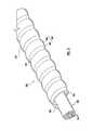
- FIG. 5is a perspective view of a third example embodiment of an armored fiber optic assembly.
- FIG. 6is a perspective view of a portion of an extrusion die that can be used to form the fiber optic assembly of FIG. 5 .
- FIG. 7is a perspective view of a fourth example embodiment of an armored fiber optic assembly.
- FIG. 1is a perspective cut-away view of an armored fiber optic assembly 120 including a core fiber optic assembly 30 disposed within a dielectric armor 150 .
- the dielectric armor 150is non-conductive and has an outer surface 152 that includes an armor profile 154 generally formed in a spiral along a longitudinal axis.
- armor profilemeans that the outer surface has an undulating surface along its length that looks similar to conventional metal armors (i.e., a undulating shape along the length of the armor).
- the dielectric armor 150is advantageous in that it both provides crush resistance and recovers to assume its original shape when subjected to crush loads.
- the dielectric armor 150may also meet flame and/or smoke ratings, and does not require electrical grounding.
- the dielectric armor 150includes an inner layer 162 and an outer layer 164 disposed on the outer surface of the inner layer 162 .
- the inner layer 162can have the shape of a spiral “strip” that winds around the core fiber optic assembly 30 .
- the outer layer 164can be a continuous cover or coating over the exterior of the inner layer 162 .
- the inner layer 162can be more rigid than the outer layer 164 . Accordingly, the Shore D hardness of the inner layer 162 can be more than the Shore D hardness of the outer jacket layer 164 .
- An inner surface 166 of the inner layer 162may also have an armor profile.
- the outer layer 164has a “continuous annular cross-section”.
- continuous annular cross-sectionmeans there are no spiral grooves, openings, or slits that cut entirely through the layer 164 .
- the exemplary inner layer 162has the form of a strip wound around the core fiber optic assembly 30 .
- the outer layer 164can be extruded directly onto the inner layer 162 so that the two layers are bonded or adhered together.
- the inner layer 162may be constructed of a relatively rigid polymer, while the outer layer 164 can be relatively less rigid. The relatively rigid inner layer 162 accordingly provides tensile strength, resistance to crush, and other robust properties.
- the armored fiber optic assembly 120can be relatively flexible and easy to bend.
- the thickness, width, and composition of the “strip” that forms the inner layer 162can be selected to provide desirable mechanical properties.
- the outer layer 164completely covers the inner layer 162 .
- the fiber optic assembly 30is housed within and protected by the dielectric armor 150 .
- the fiber optic assembly 30is a fiber optic cable having an extruded polymer cable jacket 90 and a plurality of tight-buffered optical fibers 94 extending longitudinally through the assembly 120 within the cable jacket 90 .
- Strength elements(not shown), such as aramid fibers, may also extend longitudinally through the cable jacket 90 .
- the cable jacket 90can be omitted.
- the armor 150can be formed by coextrusion methods.
- the extrudate materials for the respective layersenter the extrusion tooling together, and may become strongly bonded together as the two extrudate materials solidify.
- the armor 150can be essentially a unitary one-piece armor of two strongly bonded polymer materials, with a cross-section of the armor shown in U.S. application Ser. No. 12/748,925, filed Mar. 29, 12010 and published as US 2010/0260459, and may have the same or similar values for pitch, band thickness and other dimensions.
- FIG. 2is a close-up, partial cross-sectional schematic view of an explanatory crosshead 204 used to armor fiber optic assemblies, as viewed in the Y-Z plane, that can be used to form the inner spiral layer 162 of the assembly shown in FIG. 1 .
- the crosshead 204includes a tip 248 having a central channel 250 with an output end 252 and in which is arranged a profile tube 260 having an outer surface 261 , an inner surface 262 that defines a tube interior 263 , a proximal (output) end 264 , and a distal end 265 .
- a profiling feature 270is located on outer surface 261 at output end 252 .
- the profiling feature 270is a protrusion such as a nub or a bump.
- the profile tube interior 263is sized to accommodate the fiber optic assembly 30 as it advances axially through the interior 263 .
- the profile tube distal end 265is centrally engaged by a gear 274 that, in turn, is driven by a motor (not shown) in a manner such that the profile tube 260 rotates within channel 250 .
- the crosshead 204further includes a die 278 arranged relative to the tip 248 to form a cone-like material channel 280 that generally surrounds the central channel 250 and that has an output end 282 in the same plane as channel output end 252 .
- the material channel 280is connected to the extruder interior 201 so as to receive extrusion material 232 therefrom and through which flows the extrusion material during the extrusion process to form the inner spiral layer 162 .
- a profile tube output end 265extends beyond the channel output end 252 such that the profiling feature 270 thereon resides adjacent material channel output end 282 .
- the profile tube 260 and the tip 248are integrated to form a unitary, one-piece tool.
- extrusion materialflows through the material channel 280 and out of the material channel output end 282 .
- the fiber optic assembly 30is fed through the profile tube interior 263 and out of profile tube output end 864 (and thus through the tip 248 and the die 278 ).
- the profile tube 260is rotated via the gear 274 so that profiling feature 270 redirects (i.e., shapes) the flow of the extrusion material as it flows about fiber the optic assembly 30 .
- the circular motion of the profiling feature 270diverts the flow of extrusion material.
- the combined motion of the profiling feature 270 and the linear motion of fiber optic assembly 30forms the spiral strip 162 .
- the speed at which profile tube 260 rotates relative to the motion of fiber optic assembly 30 (which may also be rotating)dictates the pitch of the spiral strip 162 .
- the axial position of the profiling feature 270 in relation to the material channel output end 282can be varied as the feature rotates in order to, for example, form varying gaps between adjacent portions of the spiral strip 162 .
- a second, conventional extrusion head(not shown) can be arranged downstream and adjacent to the assembly shown in FIG. 2 .
- the second extrusion headcan apply a continuous outer jacket layer of non-conductive polymer material over the spiral strip inner layer 162 .
- FIG. 3is a perspective cut-away view of an armored fiber optic assembly 320 including a core fiber optic assembly 30 disposed within a dielectric armor 350 .
- the dielectric armor 350is non-conductive and has an outer surface 352 that includes an armor profile 354 generally formed in a spiral along a longitudinal axis.
- the dielectric armor 350is advantageous in that it both provides crush resistance and recovers to assume its original shape when subjected to crush loads.
- the dielectric armor 350may also meet flame and/or smoke ratings, and does not require electrical grounding.
- the dielectric armor 350includes an inner layer 362 and an outer layer 364 disposed on the outer surface of the inner layer 362 .
- the outer layer 364can have the shape of a spiral “strip” that winds around the exterior of the inner layer 362 .
- the inner layer 362can be less rigid than the outer, spiral layer 364 .
- the Shore D hardness of the inner layer 362can be less than the Shore D hardness of the outer jacket layer 364 .
- An inner surface 366 of the inner layer 362may also have an armor profile.
- the inner layer 362has a continuous annular cross-section.
- the exemplary outer layer 364has the form of a strip wound around the inner layer 362 so that portions of the inner layer 362 are visible.
- the outer layer 364can be extruded directly onto the inner layer 362 so that the two layers are bonded or adhered together.
- the outer layer 364may be constructed of a relatively rigid polymer, while the inner layer 362 can be relatively less rigid.
- the relatively rigid outer layer 364accordingly provides tensile strength, resistance to crush, and other robust properties.
- the armored fiber optic assembly 320can be relatively flexible and easy to bend.
- the thickness, width, and composition of the “strip” that forms the outer layer 364can be selected to provide desirable mechanical properties.
- the outer layer 364covers at least one quarter of the surface area of the inner layer 362 .
- the fiber optic assembly 330is housed within and protected by the dielectric armor 350 .
- the fiber optic assembly 330can be similar to the core assembly 30 shown in FIG. 1 , and may be separated from the core assembly 330 by a free space or separation distance.
- the outer layer 364could cover the entirety of the inner layer 362 .
- the inner layer 362can have the form of a spiral strip wound around the fiber optic assembly, with the outer layer 364 filling in gaps in the wound strip, as well as covering the exterior of the inner layer 364 .
- the outer layer 364can be less rigid than the inner layer 362 so that the resultant armored assembly has desirable bend properties.
- the armor 350can be interlocked spirals wound in the same direction.
- the armor 350comprised of the two interlocked spirals, would have a continuous annular cross section.
- the interlocked spiralscan have a continuous annular cross section with an armor profile.
- the armor 350can be formed by coextrusion methods. For example, the extrudate materials for the respective layers enter the extrusion tooling together, and may become strongly bonded together as the two extrudate materials solidify.
- the armor 350can be essentially a unitary one-piece armor of two strongly bonded polymer materials, with a cross-section of the armor shown in U.S. application Ser. No. 12/748,925, filed Mar. 29, 2010, and may have the same or similar values for pitch, band thickness and other dimensions.
- FIG. 4is a perspective view of an explanatory extrusion apparatus 400 , that can be used to form the inner and outer armor layers.
- the extrusion apparatus 400includes a first extrusion head 404 and a second extrusion head 406 that can be arranged end-to-end with the first head 404 .
- the first extrusion head 404includes a profiling feature 470 that can rotate in order to form varying gaps in a flow of extrudate to form a spiral strip. In such an application, the first extrusion head 404 would typically form the inner armor layer. Therefore, in the arrangement of FIG. 4 , the fiber optic assembly shown in FIG.
- the illustrated second extrusion head 406does not include a profiling feature and can be conventional in form and operation.
- the extrusion apparatus 400can be modified to form the fiber optic assembly 320 as shown in FIG. 3 .
- both the first extrusion head 404 and the second extrusion head 406would be equipped with profiling features.
- the first extrusion head 404would form the inner layer 362 with a continuous armor profile.
- the second extrusion head 406would form the outer, spiral strip layer 364 over the continuous inner layer 362 by interrupting the flow of extrudate to form a spiral strip over the inner layer.
- the extrusion apparatus 400is shown as two separate heads 404 , 406 , it could be combined as a single, “coextrusion” head that is capable of forming two or more dielectric layers.
- FIG. 5is a perspective cut-away view of an armored fiber optic assembly 520 including a core fiber optic assembly 30 disposed within a dielectric armor 550 .
- the dielectric armorincludes a tubular portion 552 and a pair of rod-like elongated rails 554 extending along each side of the armor 550 .
- the tubular portion 552has an outer surface 562 having an armor profile 564 generally formed in a spiral along a longitudinal axis.
- An inner surface 566 of the armor 550may also have an armor profile.
- the armor 550has a continuous annular cross-section.
- the tubular portion 552is illustrated as comprising a single layer of dielectric material.
- the tubular portion 552can be similar in cross-section to the armor shown in U.S. application Ser. No. 12/748,925, filed Mar. 29, 2010, and may have the same or similar values for pitch, band thickness and other dimensions.
- the inclusion of the rails 554provides increased tensile strength, allowing reduced thickness of the tubular portion 552 .
- the rails 554are shown as having rectangular sections on the sides of the rails distal to the armor center. Other cross-sections, however, such as curved, oval, arcuate, etc. may also be used for the elongate rails 554 .
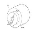
- FIG. 6is a close-up, partial cross-sectional schematic view of an explanatory profiling die 602 .
- the die 602can be used in place of the die 278 ( FIG. 2 ), for example, to form the elongate rails 554 of the armored fiber optic assembly 520 .
- the channels 608 on either side of the die 602allow additional extrudate to flow on the sides of the armor to form the elongate rails.
- the railsneed not be continuous, and can be interrupted so that a series of rails are attached to the tubular portion. All or some rails could alternatively be located on the inside of the tubular portion 552 .
- FIG. 7is a perspective cut-away view of an armored fiber optic assembly 720 including a core fiber optic assembly 30 disposed within a dielectric armor 750 .
- the dielectric armorincludes a first spiral portion 752 and a second spiral portion 754 that are wound in opposite directions and that intersect one another.
- the spiral portions 752 , 754have the form of spirally round flat strips of generally rectangular cross section.
- the counterwound spiral form of the armor 750provides flexibility to the armor that also prevents the spiral portions 752 , 754 from collapsing onto the core assembly 30 .
- the armor 750need not be secured to the core assembly 30 and may be separated from the core assembly 30 by a free space or separation distance.
- the armor 750includes generally diamond shaped, curved openings 760 through which the core assembly is visible.
- This armor 750can be formed by two counterrotating profiling projections.
- both extrusion crossheads 404 , 406could be provided with profiling features arranged to form spiral strips that rotate in opposite directions and overlap.
- the openings 760can be formed in the armor by intermittently blocking the flow of extrudate.
- the core fiber optic assemblies 30 , 330 discussed in the context of the above-described embodimentsmay be a stranded tube cable, monotube cable, micromodule cable, slotted core cable, loose fibers, tube assemblies, or the like.
- fiber optic assemblies according to the present embodimentscan include any suitable components such as water-blocking or water-swelling components, flame-retardant components such as tapes, coatings, or other suitable components.
- the fiber optic assembly 30may have any suitable fiber count such as 6, 12 or 24-fiber MIC® cables available from Corning Cable Systems of Hickory, N.C.
- the core assemblies shown in the present embodimentscan be separated from the interior surface of the armor by a median separation in the range of about 0.1-1.5 millimeters. Alternatively, the armor can be relatively tightly conforming to the surface of the core assembly.
- the embodiments discussed abovemay describe specific materials for assembly components to meet desired mechanical and burn characteristics.
- the armored fiber optic assembliesmay be flame-retardant and may have a desired flame-retardant rating depending on the intended space, such as plenum-rated, riser-rated, general-purpose, low-smoke zero-halogen (LSZH), or the like.
- LSZHlow-smoke zero-halogen
- Suitable polymer materials for the armorsmay be selected from one or more of the following materials to meet the desired rating: polyvinyl chloride (PVC), polyvinylidene fluoride (PVDF), flame-retardant polyethylene (FRPE), chlorinated polyvinyl chloride (CPVC), polytetraflourethylene (PTFE), polyether-ether keytone (PEEK), Fiber-Reinforced Polymer (FRP), low-smoke zero-halogen (LSZH), polybutylene terephthalate (PBT), polycarbonate (PC), polyethylene (PE), polypropylene (PP), polyethylene terephthalate (PETE), and acrylonitrile-butadiene-styrene (ABS).
- PVCpolyvinyl chloride
- PVDFpolyvinylidene fluoride
- FRPEflame-retardant polyethylene
- CPVCchlorinated polyvinyl chloride
- CPVCchlorinated polyvinyl chloride
- PVCs available from Teknor Apex under the tradenames FG RE 8015A, 8015B and 8015Dmay also be used.
- the terms “polymer” and “polymeric”indicate materials comprised primarily of polymers, but allow for the inclusion of non-polymer additives and other materials, such as fire-retardant compounds, etc., and the inclusion of multiple polymers in a blend.
- the term “polymer”is intended to encompass copolymers, for example.
Landscapes
- Physics & Mathematics (AREA)
- General Physics & Mathematics (AREA)
- Optics & Photonics (AREA)
- Engineering & Computer Science (AREA)
- Manufacturing & Machinery (AREA)
- Extrusion Moulding Of Plastics Or The Like (AREA)
- Insulated Conductors (AREA)
Abstract
Description
Claims (11)
Priority Applications (2)
| Application Number | Priority Date | Filing Date | Title |
|---|---|---|---|
| US13/089,296US9170390B2 (en) | 2010-04-23 | 2011-04-18 | Armored fiber optic assemblies and methods of forming fiber optic assemblies |
| US14/863,639US20160011392A1 (en) | 2010-04-23 | 2015-09-24 | Armored fiber optic assemblies and methods of forming fiber optic assemblies |
Applications Claiming Priority (2)
| Application Number | Priority Date | Filing Date | Title |
|---|---|---|---|
| US32733510P | 2010-04-23 | 2010-04-23 | |
| US13/089,296US9170390B2 (en) | 2010-04-23 | 2011-04-18 | Armored fiber optic assemblies and methods of forming fiber optic assemblies |
Related Child Applications (1)
| Application Number | Title | Priority Date | Filing Date |
|---|---|---|---|
| US14/863,639DivisionUS20160011392A1 (en) | 2010-04-23 | 2015-09-24 | Armored fiber optic assemblies and methods of forming fiber optic assemblies |
Publications (2)
| Publication Number | Publication Date |
|---|---|
| US20110262087A1 US20110262087A1 (en) | 2011-10-27 |
| US9170390B2true US9170390B2 (en) | 2015-10-27 |
Family
ID=44815851
Family Applications (2)
| Application Number | Title | Priority Date | Filing Date |
|---|---|---|---|
| US13/089,296Active2034-06-01US9170390B2 (en) | 2010-04-23 | 2011-04-18 | Armored fiber optic assemblies and methods of forming fiber optic assemblies |
| US14/863,639AbandonedUS20160011392A1 (en) | 2010-04-23 | 2015-09-24 | Armored fiber optic assemblies and methods of forming fiber optic assemblies |
Family Applications After (1)
| Application Number | Title | Priority Date | Filing Date |
|---|---|---|---|
| US14/863,639AbandonedUS20160011392A1 (en) | 2010-04-23 | 2015-09-24 | Armored fiber optic assemblies and methods of forming fiber optic assemblies |
Country Status (1)
| Country | Link |
|---|---|
| US (2) | US9170390B2 (en) |
Cited By (1)
| Publication number | Priority date | Publication date | Assignee | Title |
|---|---|---|---|---|
| US10598882B2 (en)* | 2009-04-30 | 2020-03-24 | Corning Optical Communications LLC | Armored fiber optic assemblies and methods of forming fiber optic assemblies |
Families Citing this family (10)
| Publication number | Priority date | Publication date | Assignee | Title |
|---|---|---|---|---|
| US7702203B1 (en) | 2008-10-30 | 2010-04-20 | Corning Cable Systems Llc | Armored fiber optic assemblies and methods of making the same |
| US8463095B2 (en)* | 2009-04-09 | 2013-06-11 | Corning Cable Systems Llc | Armored fiber optic assemblies and methods of forming fiber optic assemblies |
| US8331748B2 (en) | 2009-09-30 | 2012-12-11 | Corning Cable Systems Llc | Armored fiber optic assemblies and methods employing bend-resistant multimode fiber |
| CN103439774B (en)* | 2013-08-01 | 2016-01-20 | 江苏河阳线缆有限公司 | Spring cable |
| US9579955B2 (en)* | 2014-08-26 | 2017-02-28 | Magna Mirros Of America, Inc. | Rear slider window assembly with heated movable window |
| CN106356148B (en)* | 2016-10-25 | 2017-12-05 | 浙江金冠特种变压器有限公司 | A kind of easy structure mould for manufacturing spring armor |
| US10524313B2 (en) | 2017-02-09 | 2019-12-31 | Magna Mirrors Of America, Inc. | Rear slider window assembly with laminated heating element |
| CN209167604U (en)* | 2018-06-27 | 2019-07-26 | 罗森伯格技术(昆山)有限公司 | A kind of outdoor armored optical cable |
| US12054035B2 (en) | 2019-08-08 | 2024-08-06 | Magna Mirrors Of America, Inc. | Vehicular rear window assembly with continuous heater trace |
| CN112863745A (en)* | 2021-01-13 | 2021-05-28 | 魏东 | Coaxial photoelectric composite cable structure |
Citations (39)
| Publication number | Priority date | Publication date | Assignee | Title |
|---|---|---|---|---|
| US4181647A (en) | 1973-01-11 | 1980-01-01 | Phillips Cables Limited | Process for extrusion coating of a wire with a cellular thermoplastic resin material |
| US4514036A (en) | 1980-10-10 | 1985-04-30 | Raydex International Limited | Cable having a laminated plastic insulating sheath |
| US4548664A (en)* | 1983-07-27 | 1985-10-22 | Les Cables De Lyon | Method of injecting a viscous filler material into fiber-receiving grooves in the core of an optical fiber cable |
| CN87103827A (en) | 1986-05-28 | 1988-04-06 | 美国电话电报公司 | Optical cables with non-metallic armor systems |
| US4814133A (en) | 1986-07-24 | 1989-03-21 | Ube-Nitto Kasei Co., Ltd. | Method of forming the spacer of an optical fiber cable |
| US4818060A (en)* | 1987-03-31 | 1989-04-04 | American Telephone And Telegraph Company, At&T Bell Laboratories | Optical fiber building cables |
| US4946237A (en) | 1989-06-30 | 1990-08-07 | At&T Bell Laboratories | Cable having non-metallic armoring layer |
| US5126167A (en) | 1990-06-13 | 1992-06-30 | Ube-Nitto Kasei Co., Ltd. | Process of manufacturing a fiber reinforced plastic armored cable |
| WO1993009457A1 (en) | 1991-11-08 | 1993-05-13 | Anthony John Stockman | Optical fibre sheathing |
| US5305411A (en) | 1993-02-26 | 1994-04-19 | At&T Bell Laboratories | Dielectric optical fiber cables which are magnetically locatable |
| WO1995035196A1 (en) | 1994-06-17 | 1995-12-28 | Miniflex Limited | Apparatus for forming grooves in cylindrical surfaces |
| US5615293A (en) | 1996-01-30 | 1997-03-25 | W. L. Gore & Associates, Inc. | Fiber optic cable assembly for facilitating the installation thereof in a structure |
| US5892873A (en) | 1996-01-19 | 1999-04-06 | Alcatel Alsthom Compagnie Generale D'electricite | Optical cable with extruded peripheral reinforcements |
| US5920671A (en) | 1996-02-13 | 1999-07-06 | Gore Enterprise Holdings, Inc. | Signal transmission assembly having reduced-friction and concentrated load distribution element for synthetic strength members |
| JPH11223752A (en) | 1998-02-05 | 1999-08-17 | Matsushita Electric Ind Co Ltd | Fiber optic cable |
| US6233384B1 (en) | 1999-02-11 | 2001-05-15 | Gore Enterprise Holdings, Inc. | Ruggedized fiber optic cable |
| US20010007604A1 (en) | 1999-03-31 | 2001-07-12 | Lail Jason C. | Fiber optic cable with profiled group of optical fibers |
| US20030161596A1 (en) | 2000-12-26 | 2003-08-28 | Register James A. | Fiber optic ribbon interconnects and breakout cables |
| US20030202756A1 (en) | 1998-06-22 | 2003-10-30 | Hurley William C. | Self-supporting cables and an apparatus and methods for making the same |
| US20040120663A1 (en) | 2002-12-19 | 2004-06-24 | Lail Jason C. | Optical tube assembly having a dry insert and methods of making the same |
| US20040234215A1 (en)* | 2003-05-23 | 2004-11-25 | Serrano Jorge R. | Exterior installation of armored fiber optic cable |
| US20050013573A1 (en) | 2003-07-18 | 2005-01-20 | Lochkovic Gregory A. | Fiber optic articles, assemblies, and cables having optical waveguides |
| US20050098342A1 (en) | 2002-12-18 | 2005-05-12 | Itaru Sakabe | Communication cable, and communication wire protecting tube |
| US6898354B2 (en) | 2002-10-28 | 2005-05-24 | Judd Wire, Inc. | Fiber optic cable demonstrating improved dimensional stability |
| US6906264B1 (en) | 2004-06-17 | 2005-06-14 | Southwire Company | Color-coded armored cable |
| US6909264B2 (en) | 2002-06-28 | 2005-06-21 | Stmicroelectronics S.R.L. | Voltage regulator with very quick response |
| US20050196113A1 (en) | 2001-11-12 | 2005-09-08 | Hurley William C. | High density fiber optic cable |
| US20060029340A1 (en) | 2004-08-09 | 2006-02-09 | Sumitomo Electric Lightwave Corp. | Locatable dielectric optical fiber cable having easily removable locating element |
| US7025509B2 (en) | 2004-02-16 | 2006-04-11 | Dafacom Solutions, Inc. | Cable sleeve and method of installation |
| US20060280413A1 (en) | 2005-06-08 | 2006-12-14 | Commscope Solutions Properties, Llc | Fiber optic cables and methods for forming the same |
| US7196272B2 (en) | 2002-05-01 | 2007-03-27 | Cable Components Group, Llc. | High performance support-separators for communications cables |
| US7202418B2 (en) | 2004-01-07 | 2007-04-10 | Cable Components Group, Llc | Flame retardant and smoke suppressant composite high performance support-separators and conduit tubes |
| US7266886B2 (en) | 2001-12-19 | 2007-09-11 | Acome Societe Cooperative De Travailleurs | Method of continuously fabricating a corrugated coaxial cable |
| US20080253723A1 (en) | 2007-04-11 | 2008-10-16 | Sumitomo Electric Lightwave Corp. | Optical fiber ribbon drop cable |
| US20090139084A1 (en) | 2007-11-30 | 2009-06-04 | Commscope, Inc. Of North Carolina | Armored cable and methods and apparatus for forming the same |
| US7702203B1 (en)* | 2008-10-30 | 2010-04-20 | Corning Cable Systems Llc | Armored fiber optic assemblies and methods of making the same |
| US20100278492A1 (en) | 2009-04-30 | 2010-11-04 | Bohler Gregory B | Armored Fiber Optic Assemblies and Methods of Forming Fiber Optic Assemblies |
| US7844148B2 (en) | 2004-09-29 | 2010-11-30 | Miniflex Limited | Linear member |
| US8331748B2 (en) | 2009-09-30 | 2012-12-11 | Corning Cable Systems Llc | Armored fiber optic assemblies and methods employing bend-resistant multimode fiber |
- 2011
- 2011-04-18USUS13/089,296patent/US9170390B2/enactiveActive
- 2015
- 2015-09-24USUS14/863,639patent/US20160011392A1/ennot_activeAbandoned
Patent Citations (46)
| Publication number | Priority date | Publication date | Assignee | Title |
|---|---|---|---|---|
| US4181647A (en) | 1973-01-11 | 1980-01-01 | Phillips Cables Limited | Process for extrusion coating of a wire with a cellular thermoplastic resin material |
| US4514036A (en) | 1980-10-10 | 1985-04-30 | Raydex International Limited | Cable having a laminated plastic insulating sheath |
| US4548664A (en)* | 1983-07-27 | 1985-10-22 | Les Cables De Lyon | Method of injecting a viscous filler material into fiber-receiving grooves in the core of an optical fiber cable |
| CN87103827A (en) | 1986-05-28 | 1988-04-06 | 美国电话电报公司 | Optical cables with non-metallic armor systems |
| US4743085A (en) | 1986-05-28 | 1988-05-10 | American Telephone And Telegraph Co., At&T Bell Laboratories | Optical fiber cable having non-metallic sheath system |
| US4814133A (en) | 1986-07-24 | 1989-03-21 | Ube-Nitto Kasei Co., Ltd. | Method of forming the spacer of an optical fiber cable |
| US4818060A (en)* | 1987-03-31 | 1989-04-04 | American Telephone And Telegraph Company, At&T Bell Laboratories | Optical fiber building cables |
| US4946237A (en) | 1989-06-30 | 1990-08-07 | At&T Bell Laboratories | Cable having non-metallic armoring layer |
| US5126167A (en) | 1990-06-13 | 1992-06-30 | Ube-Nitto Kasei Co., Ltd. | Process of manufacturing a fiber reinforced plastic armored cable |
| WO1993009457A1 (en) | 1991-11-08 | 1993-05-13 | Anthony John Stockman | Optical fibre sheathing |
| US5305411A (en) | 1993-02-26 | 1994-04-19 | At&T Bell Laboratories | Dielectric optical fiber cables which are magnetically locatable |
| WO1995035196A1 (en) | 1994-06-17 | 1995-12-28 | Miniflex Limited | Apparatus for forming grooves in cylindrical surfaces |
| US5892873A (en) | 1996-01-19 | 1999-04-06 | Alcatel Alsthom Compagnie Generale D'electricite | Optical cable with extruded peripheral reinforcements |
| US5615293A (en) | 1996-01-30 | 1997-03-25 | W. L. Gore & Associates, Inc. | Fiber optic cable assembly for facilitating the installation thereof in a structure |
| US5920671A (en) | 1996-02-13 | 1999-07-06 | Gore Enterprise Holdings, Inc. | Signal transmission assembly having reduced-friction and concentrated load distribution element for synthetic strength members |
| JPH11223752A (en) | 1998-02-05 | 1999-08-17 | Matsushita Electric Ind Co Ltd | Fiber optic cable |
| US20030202756A1 (en) | 1998-06-22 | 2003-10-30 | Hurley William C. | Self-supporting cables and an apparatus and methods for making the same |
| US6233384B1 (en) | 1999-02-11 | 2001-05-15 | Gore Enterprise Holdings, Inc. | Ruggedized fiber optic cable |
| US20010007604A1 (en) | 1999-03-31 | 2001-07-12 | Lail Jason C. | Fiber optic cable with profiled group of optical fibers |
| US20030161596A1 (en) | 2000-12-26 | 2003-08-28 | Register James A. | Fiber optic ribbon interconnects and breakout cables |
| US20050196113A1 (en) | 2001-11-12 | 2005-09-08 | Hurley William C. | High density fiber optic cable |
| US7266886B2 (en) | 2001-12-19 | 2007-09-11 | Acome Societe Cooperative De Travailleurs | Method of continuously fabricating a corrugated coaxial cable |
| US7196272B2 (en) | 2002-05-01 | 2007-03-27 | Cable Components Group, Llc. | High performance support-separators for communications cables |
| US6909264B2 (en) | 2002-06-28 | 2005-06-21 | Stmicroelectronics S.R.L. | Voltage regulator with very quick response |
| US6898354B2 (en) | 2002-10-28 | 2005-05-24 | Judd Wire, Inc. | Fiber optic cable demonstrating improved dimensional stability |
| US20050098342A1 (en) | 2002-12-18 | 2005-05-12 | Itaru Sakabe | Communication cable, and communication wire protecting tube |
| US7064276B2 (en) | 2002-12-18 | 2006-06-20 | Sumitomo Electric Industries, Ltd. | Communication cable, and communication wire protecting tube |
| US7336873B2 (en) | 2002-12-19 | 2008-02-26 | Corning Cable Systems, Llc. | Optical tube assembly having a dry insert and methods of making the same |
| US20040120663A1 (en) | 2002-12-19 | 2004-06-24 | Lail Jason C. | Optical tube assembly having a dry insert and methods of making the same |
| US20040234215A1 (en)* | 2003-05-23 | 2004-11-25 | Serrano Jorge R. | Exterior installation of armored fiber optic cable |
| US20050013573A1 (en) | 2003-07-18 | 2005-01-20 | Lochkovic Gregory A. | Fiber optic articles, assemblies, and cables having optical waveguides |
| US7202418B2 (en) | 2004-01-07 | 2007-04-10 | Cable Components Group, Llc | Flame retardant and smoke suppressant composite high performance support-separators and conduit tubes |
| US7025509B2 (en) | 2004-02-16 | 2006-04-11 | Dafacom Solutions, Inc. | Cable sleeve and method of installation |
| US6906264B1 (en) | 2004-06-17 | 2005-06-14 | Southwire Company | Color-coded armored cable |
| US20060029340A1 (en) | 2004-08-09 | 2006-02-09 | Sumitomo Electric Lightwave Corp. | Locatable dielectric optical fiber cable having easily removable locating element |
| US7313304B2 (en) | 2004-08-09 | 2007-12-25 | Sumitomo Electric Lightwave Corp. | Locatable dielectric optical fiber cable having easily removable locating element |
| US7844148B2 (en) | 2004-09-29 | 2010-11-30 | Miniflex Limited | Linear member |
| US20060280413A1 (en) | 2005-06-08 | 2006-12-14 | Commscope Solutions Properties, Llc | Fiber optic cables and methods for forming the same |
| US20080253723A1 (en) | 2007-04-11 | 2008-10-16 | Sumitomo Electric Lightwave Corp. | Optical fiber ribbon drop cable |
| US20090139084A1 (en) | 2007-11-30 | 2009-06-04 | Commscope, Inc. Of North Carolina | Armored cable and methods and apparatus for forming the same |
| US7845069B2 (en) | 2007-11-30 | 2010-12-07 | Commscope, Inc. Of North Carolina | Methods for forming armored cable assembly |
| US7702203B1 (en)* | 2008-10-30 | 2010-04-20 | Corning Cable Systems Llc | Armored fiber optic assemblies and methods of making the same |
| US8218925B2 (en) | 2008-10-30 | 2012-07-10 | Corning Cable Systems Llc | Armored fiber optic assemblies and methods of making the same |
| US20120251061A1 (en) | 2008-10-30 | 2012-10-04 | Bohler Gregory B | Armor for a fiber optic assembly |
| US20100278492A1 (en) | 2009-04-30 | 2010-11-04 | Bohler Gregory B | Armored Fiber Optic Assemblies and Methods of Forming Fiber Optic Assemblies |
| US8331748B2 (en) | 2009-09-30 | 2012-12-11 | Corning Cable Systems Llc | Armored fiber optic assemblies and methods employing bend-resistant multimode fiber |
Non-Patent Citations (17)
| Title |
|---|
| Advisory Action for U.S. Appl. No. 12/768,158 mailed Nov. 6, 2012, 4 pages. |
| Final Office Action for U.S. Appl. No. 12/768,158 mailed Aug. 16, 2012, 19 pages. |
| First Office Action for Chinese Patent Application No. 200910209613.5 mailed Aug. 31, 2012, 7 pages. |
| First Office Action for Chinese Patent Application No. 201010146116.8, mailed Nov. 12, 2012, 5 pages. |
| Non-Final Office Action for U.S. Appl. No. 12/261,645 mailed Oct. 6, 2009, 13 pages. |
| Non-Final Office Action for U.S. Appl. No. 12/718,044 mailed Jan. 6, 2012, 12 pages. |
| Non-Final Office Action for U.S. Appl. No. 12/748,925 mailed Jul. 24, 2012, 13 pages. |
| Non-Final Office Action for U.S. Appl. No. 12/768,158 mailed Jan. 5, 2012, 18 pages. |
| Non-Final Office Action for U.S. Appl. No. 13/494,129 mailed Aug. 16, 2012, 7 pages. |
| Non-Final Office Action for U.S. Appl. No. 13/673,203 mailed Feb. 1, 2013, 9 pages. |
| Notice of Allowance for U.S. Appl. No. 12/261,645 mailed Feb. 12, 2010, 8 pages. |
| Notice of Allowance for U.S. Appl. No. 12/718,044 mailed Apr. 6, 2012, 8 pages. |
| Notice of Allowance for U.S. Appl. No. 12/748,925 mailed Nov. 27, 2012, 9 pages. |
| Notice of Allowance for U.S. Appl. No. 12/888,865 mailed Sep. 19, 2012, 9 pages. |
| Notice of Allowance for U.S. Appl. No. 13/494,129 mailed Oct. 29, 2012, 9 pages. |
| Restriction Requirement for U.S. Appl. No. 12/261,645 mailed Jun. 26, 2009, 9 pages. |
| Restriction Requirement for U.S. Appl. No. 12/748,925 mailed Apr. 27, 2012, 6 pages. |
Cited By (1)
| Publication number | Priority date | Publication date | Assignee | Title |
|---|---|---|---|---|
| US10598882B2 (en)* | 2009-04-30 | 2020-03-24 | Corning Optical Communications LLC | Armored fiber optic assemblies and methods of forming fiber optic assemblies |
Also Published As
| Publication number | Publication date |
|---|---|
| US20160011392A1 (en) | 2016-01-14 |
| US20110262087A1 (en) | 2011-10-27 |
Similar Documents
| Publication | Publication Date | Title |
|---|---|---|
| US9170390B2 (en) | Armored fiber optic assemblies and methods of forming fiber optic assemblies | |
| US8218925B2 (en) | Armored fiber optic assemblies and methods of making the same | |
| US10598882B2 (en) | Armored fiber optic assemblies and methods of forming fiber optic assemblies | |
| US8331748B2 (en) | Armored fiber optic assemblies and methods employing bend-resistant multimode fiber | |
| EP1942360B1 (en) | Highly flexible water-proof, rodent-proof cables particularly useful as optical communication cables | |
| US8724947B2 (en) | Armored fiber optic assemblies and methods of forming fiber optic assemblies | |
| CN109416437A (en) | Optical fiber cable with the elongated strength component being recessed in armor | |
| US10983294B2 (en) | Deployable fiber optic cable with partially bonded ribbon fibers | |
| WO2017022531A1 (en) | Optical fiber cable | |
| EP1597619A1 (en) | Loose tube optical cable | |
| MX2010010601A (en) | Multi-fiber fiber optic cable. | |
| US20030102043A1 (en) | High density fiber optic cable inner ducts | |
| EP3640694A1 (en) | Slot type optical cable | |
| CN223308437U (en) | A central tube optical cable | |
| CN104199160A (en) | Layer-stranding cable with reinforcers | |
| AU2015203046B2 (en) | Armored fiber optic assemblies and methods of forming fiber optic assemblies | |
| CN102364366A (en) | Layer stranded cable with strengthening member in sheath | |
| RU63553U1 (en) | HEATED FIBER OPTICAL CABLE | |
| FI85311B (en) | Element design for a cable, like an optical cable | |
| HK40019866A (en) | Slot-type optical cable |
Legal Events
| Date | Code | Title | Description |
|---|---|---|---|
| AS | Assignment | Owner name:CORNING CABLE SYSTEMS LLC, NORTH CAROLINA Free format text:ASSIGNMENT OF ASSIGNORS INTEREST;ASSIGNORS:BOHLER, GREGORY B.;GREENWOOD, III, JULIAN L.;GREER, KEITH A.;AND OTHERS;SIGNING DATES FROM 20110412 TO 20110413;REEL/FRAME:026147/0612 | |
| STCF | Information on status: patent grant | Free format text:PATENTED CASE | |
| AS | Assignment | Owner name:CORNING OPTICAL COMMUNICATIONS LLC, NORTH CAROLINA Free format text:CHANGE OF NAME;ASSIGNOR:CORNING CABLE SYSTEMS LLC;REEL/FRAME:040126/0818 Effective date:20140114 | |
| AS | Assignment | Owner name:CCS TECHNOLOGY, INC., DELAWARE Free format text:ASSIGNMENT OF ASSIGNORS INTEREST;ASSIGNOR:CORNING OPTICAL COMMUNICATIONS LLC;REEL/FRAME:040663/0047 Effective date:20160419 | |
| AS | Assignment | Owner name:CORNING OPTICAL COMMUNICATIONS LLC, NORTH CAROLINA Free format text:MERGER;ASSIGNORS:CCS TECHNOLOGY, INC.;CORNING OPTICAL COMMUNICATIONS BRANDS, INC.;REEL/FRAME:043601/0427 Effective date:20170630 | |
| MAFP | Maintenance fee payment | Free format text:PAYMENT OF MAINTENANCE FEE, 4TH YEAR, LARGE ENTITY (ORIGINAL EVENT CODE: M1551); ENTITY STATUS OF PATENT OWNER: LARGE ENTITY Year of fee payment:4 | |
| MAFP | Maintenance fee payment | Free format text:PAYMENT OF MAINTENANCE FEE, 8TH YEAR, LARGE ENTITY (ORIGINAL EVENT CODE: M1552); ENTITY STATUS OF PATENT OWNER: LARGE ENTITY Year of fee payment:8 |