US9168151B2 - Spinal fixation system - Google Patents
Spinal fixation systemDownload PDFInfo
- Publication number
- US9168151B2 US9168151B2US14/137,040US201314137040AUS9168151B2US 9168151 B2US9168151 B2US 9168151B2US 201314137040 AUS201314137040 AUS 201314137040AUS 9168151 B2US9168151 B2US 9168151B2
- Authority
- US
- United States
- Prior art keywords
- pedicle screw
- receiver
- fixation system
- coupling
- spinal fixation
- Prior art date
- Legal status (The legal status is an assumption and is not a legal conclusion. Google has not performed a legal analysis and makes no representation as to the accuracy of the status listed.)
- Expired - Lifetime, expires
Links
Images


Classifications
- A—HUMAN NECESSITIES
- A61—MEDICAL OR VETERINARY SCIENCE; HYGIENE
- A61F—FILTERS IMPLANTABLE INTO BLOOD VESSELS; PROSTHESES; DEVICES PROVIDING PATENCY TO, OR PREVENTING COLLAPSING OF, TUBULAR STRUCTURES OF THE BODY, e.g. STENTS; ORTHOPAEDIC, NURSING OR CONTRACEPTIVE DEVICES; FOMENTATION; TREATMENT OR PROTECTION OF EYES OR EARS; BANDAGES, DRESSINGS OR ABSORBENT PADS; FIRST-AID KITS
- A61F2/00—Filters implantable into blood vessels; Prostheses, i.e. artificial substitutes or replacements for parts of the body; Appliances for connecting them with the body; Devices providing patency to, or preventing collapsing of, tubular structures of the body, e.g. stents
- A61F2/02—Prostheses implantable into the body
- A61F2/30—Joints
- A61F2/44—Joints for the spine, e.g. vertebrae, spinal discs
- A61F2/4455—Joints for the spine, e.g. vertebrae, spinal discs for the fusion of spinal bodies, e.g. intervertebral fusion of adjacent spinal bodies, e.g. fusion cages
- A—HUMAN NECESSITIES
- A61—MEDICAL OR VETERINARY SCIENCE; HYGIENE
- A61B—DIAGNOSIS; SURGERY; IDENTIFICATION
- A61B17/00—Surgical instruments, devices or methods
- A61B17/16—Instruments for performing osteoclasis; Drills or chisels for bones; Trepans
- A61B17/1662—Instruments for performing osteoclasis; Drills or chisels for bones; Trepans for particular parts of the body
- A61B17/1671—Instruments for performing osteoclasis; Drills or chisels for bones; Trepans for particular parts of the body for the spine
- A—HUMAN NECESSITIES
- A61—MEDICAL OR VETERINARY SCIENCE; HYGIENE
- A61B—DIAGNOSIS; SURGERY; IDENTIFICATION
- A61B17/00—Surgical instruments, devices or methods
- A61B17/56—Surgical instruments or methods for treatment of bones or joints; Devices specially adapted therefor
- A61B17/58—Surgical instruments or methods for treatment of bones or joints; Devices specially adapted therefor for osteosynthesis, e.g. bone plates, screws or setting implements
- A61B17/68—Internal fixation devices, including fasteners and spinal fixators, even if a part thereof projects from the skin
- A61B17/70—Spinal positioners or stabilisers, e.g. stabilisers comprising fluid filler in an implant
- A61B17/7001—Screws or hooks combined with longitudinal elements which do not contact vertebrae
- A61B17/7002—Longitudinal elements, e.g. rods
- A61B17/7004—Longitudinal elements, e.g. rods with a cross-section which varies along its length
- A61B17/7005—Parts of the longitudinal elements, e.g. their ends, being specially adapted to fit in the screw or hook heads
- A—HUMAN NECESSITIES
- A61—MEDICAL OR VETERINARY SCIENCE; HYGIENE
- A61B—DIAGNOSIS; SURGERY; IDENTIFICATION
- A61B17/00—Surgical instruments, devices or methods
- A61B17/56—Surgical instruments or methods for treatment of bones or joints; Devices specially adapted therefor
- A61B17/58—Surgical instruments or methods for treatment of bones or joints; Devices specially adapted therefor for osteosynthesis, e.g. bone plates, screws or setting implements
- A61B17/68—Internal fixation devices, including fasteners and spinal fixators, even if a part thereof projects from the skin
- A61B17/70—Spinal positioners or stabilisers, e.g. stabilisers comprising fluid filler in an implant
- A61B17/7001—Screws or hooks combined with longitudinal elements which do not contact vertebrae
- A61B17/7002—Longitudinal elements, e.g. rods
- A61B17/7004—Longitudinal elements, e.g. rods with a cross-section which varies along its length
- A61B17/7007—Parts of the longitudinal elements, e.g. their ends, being specially adapted to fit around the screw or hook heads
- A—HUMAN NECESSITIES
- A61—MEDICAL OR VETERINARY SCIENCE; HYGIENE
- A61B—DIAGNOSIS; SURGERY; IDENTIFICATION
- A61B17/00—Surgical instruments, devices or methods
- A61B17/56—Surgical instruments or methods for treatment of bones or joints; Devices specially adapted therefor
- A61B17/58—Surgical instruments or methods for treatment of bones or joints; Devices specially adapted therefor for osteosynthesis, e.g. bone plates, screws or setting implements
- A61B17/68—Internal fixation devices, including fasteners and spinal fixators, even if a part thereof projects from the skin
- A61B17/70—Spinal positioners or stabilisers, e.g. stabilisers comprising fluid filler in an implant
- A61B17/7001—Screws or hooks combined with longitudinal elements which do not contact vertebrae
- A61B17/7002—Longitudinal elements, e.g. rods
- A61B17/701—Longitudinal elements with a non-circular, e.g. rectangular, cross-section
- A—HUMAN NECESSITIES
- A61—MEDICAL OR VETERINARY SCIENCE; HYGIENE
- A61B—DIAGNOSIS; SURGERY; IDENTIFICATION
- A61B17/00—Surgical instruments, devices or methods
- A61B17/56—Surgical instruments or methods for treatment of bones or joints; Devices specially adapted therefor
- A61B17/58—Surgical instruments or methods for treatment of bones or joints; Devices specially adapted therefor for osteosynthesis, e.g. bone plates, screws or setting implements
- A61B17/68—Internal fixation devices, including fasteners and spinal fixators, even if a part thereof projects from the skin
- A61B17/70—Spinal positioners or stabilisers, e.g. stabilisers comprising fluid filler in an implant
- A61B17/7001—Screws or hooks combined with longitudinal elements which do not contact vertebrae
- A61B17/7032—Screws or hooks with U-shaped head or back through which longitudinal rods pass
- A—HUMAN NECESSITIES
- A61—MEDICAL OR VETERINARY SCIENCE; HYGIENE
- A61B—DIAGNOSIS; SURGERY; IDENTIFICATION
- A61B17/00—Surgical instruments, devices or methods
- A61B17/56—Surgical instruments or methods for treatment of bones or joints; Devices specially adapted therefor
- A61B17/58—Surgical instruments or methods for treatment of bones or joints; Devices specially adapted therefor for osteosynthesis, e.g. bone plates, screws or setting implements
- A61B17/68—Internal fixation devices, including fasteners and spinal fixators, even if a part thereof projects from the skin
- A61B17/70—Spinal positioners or stabilisers, e.g. stabilisers comprising fluid filler in an implant
- A61B17/7001—Screws or hooks combined with longitudinal elements which do not contact vertebrae
- A61B17/7035—Screws or hooks, wherein a rod-clamping part and a bone-anchoring part can pivot relative to each other
- A61B17/7037—Screws or hooks, wherein a rod-clamping part and a bone-anchoring part can pivot relative to each other wherein pivoting is blocked when the rod is clamped
- A—HUMAN NECESSITIES
- A61—MEDICAL OR VETERINARY SCIENCE; HYGIENE
- A61B—DIAGNOSIS; SURGERY; IDENTIFICATION
- A61B17/00—Surgical instruments, devices or methods
- A61B17/56—Surgical instruments or methods for treatment of bones or joints; Devices specially adapted therefor
- A61B17/58—Surgical instruments or methods for treatment of bones or joints; Devices specially adapted therefor for osteosynthesis, e.g. bone plates, screws or setting implements
- A61B17/68—Internal fixation devices, including fasteners and spinal fixators, even if a part thereof projects from the skin
- A61B17/70—Spinal positioners or stabilisers, e.g. stabilisers comprising fluid filler in an implant
- A61B17/7001—Screws or hooks combined with longitudinal elements which do not contact vertebrae
- A61B17/7035—Screws or hooks, wherein a rod-clamping part and a bone-anchoring part can pivot relative to each other
- A61B17/704—Screws or hooks, wherein a rod-clamping part and a bone-anchoring part can pivot relative to each other the longitudinal element passing through a ball-joint in the screw head
- A—HUMAN NECESSITIES
- A61—MEDICAL OR VETERINARY SCIENCE; HYGIENE
- A61B—DIAGNOSIS; SURGERY; IDENTIFICATION
- A61B17/00—Surgical instruments, devices or methods
- A61B17/56—Surgical instruments or methods for treatment of bones or joints; Devices specially adapted therefor
- A61B17/58—Surgical instruments or methods for treatment of bones or joints; Devices specially adapted therefor for osteosynthesis, e.g. bone plates, screws or setting implements
- A61B17/68—Internal fixation devices, including fasteners and spinal fixators, even if a part thereof projects from the skin
- A61B17/70—Spinal positioners or stabilisers, e.g. stabilisers comprising fluid filler in an implant
- A61B17/7001—Screws or hooks combined with longitudinal elements which do not contact vertebrae
- A61B17/7041—Screws or hooks combined with longitudinal elements which do not contact vertebrae with single longitudinal rod offset laterally from single row of screws or hooks
- A—HUMAN NECESSITIES
- A61—MEDICAL OR VETERINARY SCIENCE; HYGIENE
- A61B—DIAGNOSIS; SURGERY; IDENTIFICATION
- A61B17/00—Surgical instruments, devices or methods
- A61B17/56—Surgical instruments or methods for treatment of bones or joints; Devices specially adapted therefor
- A61B17/58—Surgical instruments or methods for treatment of bones or joints; Devices specially adapted therefor for osteosynthesis, e.g. bone plates, screws or setting implements
- A61B17/68—Internal fixation devices, including fasteners and spinal fixators, even if a part thereof projects from the skin
- A61B17/80—Cortical plates, i.e. bone plates; Instruments for holding or positioning cortical plates, or for compressing bones attached to cortical plates
- A61B17/8033—Cortical plates, i.e. bone plates; Instruments for holding or positioning cortical plates, or for compressing bones attached to cortical plates having indirect contact with screw heads, or having contact with screw heads maintained with the aid of additional components, e.g. nuts, wedges or head covers
- A61B17/8047—Cortical plates, i.e. bone plates; Instruments for holding or positioning cortical plates, or for compressing bones attached to cortical plates having indirect contact with screw heads, or having contact with screw heads maintained with the aid of additional components, e.g. nuts, wedges or head covers wherein the additional element surrounds the screw head in the plate hole
- A—HUMAN NECESSITIES
- A61—MEDICAL OR VETERINARY SCIENCE; HYGIENE
- A61B—DIAGNOSIS; SURGERY; IDENTIFICATION
- A61B17/00—Surgical instruments, devices or methods
- A61B17/56—Surgical instruments or methods for treatment of bones or joints; Devices specially adapted therefor
- A61B17/58—Surgical instruments or methods for treatment of bones or joints; Devices specially adapted therefor for osteosynthesis, e.g. bone plates, screws or setting implements
- A61B17/68—Internal fixation devices, including fasteners and spinal fixators, even if a part thereof projects from the skin
- A61B17/70—Spinal positioners or stabilisers, e.g. stabilisers comprising fluid filler in an implant
- A61B17/7001—Screws or hooks combined with longitudinal elements which do not contact vertebrae
- A61B17/7002—Longitudinal elements, e.g. rods
- A61B17/7011—Longitudinal element being non-straight, e.g. curved, angled or branched
- A—HUMAN NECESSITIES
- A61—MEDICAL OR VETERINARY SCIENCE; HYGIENE
- A61B—DIAGNOSIS; SURGERY; IDENTIFICATION
- A61B17/00—Surgical instruments, devices or methods
- A61B17/56—Surgical instruments or methods for treatment of bones or joints; Devices specially adapted therefor
- A61B17/58—Surgical instruments or methods for treatment of bones or joints; Devices specially adapted therefor for osteosynthesis, e.g. bone plates, screws or setting implements
- A61B17/68—Internal fixation devices, including fasteners and spinal fixators, even if a part thereof projects from the skin
- A61B17/84—Fasteners therefor or fasteners being internal fixation devices
- A61B17/86—Pins or screws or threaded wires; nuts therefor
- A61B17/8625—Shanks, i.e. parts contacting bone tissue
- A61B17/863—Shanks, i.e. parts contacting bone tissue with thread interrupted or changing its form along shank, other than constant taper
- A—HUMAN NECESSITIES
- A61—MEDICAL OR VETERINARY SCIENCE; HYGIENE
- A61B—DIAGNOSIS; SURGERY; IDENTIFICATION
- A61B17/00—Surgical instruments, devices or methods
- A61B17/56—Surgical instruments or methods for treatment of bones or joints; Devices specially adapted therefor
- A61B17/58—Surgical instruments or methods for treatment of bones or joints; Devices specially adapted therefor for osteosynthesis, e.g. bone plates, screws or setting implements
- A61B17/68—Internal fixation devices, including fasteners and spinal fixators, even if a part thereof projects from the skin
- A61B17/84—Fasteners therefor or fasteners being internal fixation devices
- A61B17/86—Pins or screws or threaded wires; nuts therefor
- A61B17/8685—Pins or screws or threaded wires; nuts therefor comprising multiple separate parts
- A—HUMAN NECESSITIES
- A61—MEDICAL OR VETERINARY SCIENCE; HYGIENE
- A61F—FILTERS IMPLANTABLE INTO BLOOD VESSELS; PROSTHESES; DEVICES PROVIDING PATENCY TO, OR PREVENTING COLLAPSING OF, TUBULAR STRUCTURES OF THE BODY, e.g. STENTS; ORTHOPAEDIC, NURSING OR CONTRACEPTIVE DEVICES; FOMENTATION; TREATMENT OR PROTECTION OF EYES OR EARS; BANDAGES, DRESSINGS OR ABSORBENT PADS; FIRST-AID KITS
- A61F2/00—Filters implantable into blood vessels; Prostheses, i.e. artificial substitutes or replacements for parts of the body; Appliances for connecting them with the body; Devices providing patency to, or preventing collapsing of, tubular structures of the body, e.g. stents
- A61F2/02—Prostheses implantable into the body
- A61F2/30—Joints
- A61F2/30767—Special external or bone-contacting surface, e.g. coating for improving bone ingrowth
- A61F2/30907—Nets or sleeves applied to surface of prostheses or in cement
- A61F2002/30909—Nets
Definitions
- the present inventionrelates to instrumentation and methods used in the performance of spinal fusion procedures.
- the present inventionrelates to a spinal fixation system and related surgical methods.
- the spinal columnis comprised of twenty-six interlocking vertebrae. These vertebrae are separated by disks.
- the spineprovides load-bearing support for one-half of the body's mass and it protects the nerves of the spinal column.
- the disksprovide shock absorption and facilitate the bending of the spine.
- the combination of the vertebrae and disks at each vertebral segmentallows for motion of the spine, in particular, flexing, rotation, and extension.
- the motion and support functions of the spine, in combination with the many interlocking parts and nerve roots associated with the spinal columncan result in back pain due to various reasons.
- Such back painmay result from the degeneration of disks due to age, disease, or injury.
- vertebral bodiesmay be compromised due to disease or defect, such as a tumor, or injury, such as fracture.
- spinal fusion or fixation surgeryis one way to treat back pain. Further, spinal fusion or fixation may be used to correct an abnormal curvature of the spine or stabilize the spine due to injury or disease affecting one or more disks or vertebrae.
- spinal fusion proceduretwo or more adjacent vertebrae in the spine are fused together. The fusion is typically accomplished by the utilization of spinal instrumentation including pedicle screws and associated rods or plates used to mechanically fix the vertebrae together. Pedicle screws are typically used in spinal fusion surgery because the pedicle serves as a strong mechanical attachment point to the spine.
- Bone graft materialmay be utilized to aid in the creation of bone structure between the fused vertebrae to create a single bone.
- Spinal fixation componentsvary depending on the system being utilized but typically include pedicle screws that are inserted through the pedicle and into the vertebral body.
- the pedicle screwsare attached to one another by a linking device, such as a rod or plate, that extends vertically along the row of pedicle screws that are inserted.
- a linking devicesuch as a rod or plate
- Several coupling systemsare known in the art that are used for coupling the pedicle screws to the linking device, which is oriented parallel to the spinal column.
- two columns of pedicle screws and linking devicesare used, one on each side of the spinal column. After installation, the two linking devices may be attached to one another to provide additional stabilization of that portion of the spine.
- spinal hooksmay be used, each spinal hook being coupled to a vertebra via a portion of the vertebral arch.
- the pedicle screws that are fixed to one another in a spinal fusion proceduremay not be in longitudinal alignment with one another. Accordingly, spinal fixation systems, whether utilizing a rod or a plate, strive to allow some variability in the placement of the pedicle screws while still accomplishing the goal of fixation with a single rod or plate along the pedicle screws.
- One challenge associated with the design of a spinal fixation systemis the connection between the pedicle screws and the linking device. Ideally, the number of components involved should be minimized, especially the number of components that must be threaded together (such as nuts and rods) in order to ease the assembly process and minimize the overall time of the surgical procedure.
- a spinal fixation systemthat may be utilized with a minimally invasive surgical approach, such as one that utilizes smaller access apertures or ports rather than a large incision along the entire portion of the spine being treated.
- a spinal fixation systemthat addresses the needs for a minimally invasive approach may also address the desire to utilize bone graft material along the fixation site to enhance bony in-growth.
- the inventionrelates to a spinal fixation system having a pedicle screw with a longitudinal axis and a fixation element configured to connect the pedicle screw to at least one additional pedicle screw.
- a coupling mechanismincludes a pedicle screw securing device adapted to secure the coupling mechanism to the pedicle screw and a fixation element securing device configured to secure the coupling mechanism to the fixation element.
- a fastening mechanismis configured to fasten both the pedicle screw securing device and the fixation element securing device, the fastening mechanism located along the longitudinal axis of the pedicle screw.
- the inventionfurther relates to a spinal fixation system having a pedicle screw and a fixation element configured to connect the pedicle screw to at least one additional pedicle screw.
- a coupling mechanismincludes a collet adapted to secure the coupling mechanism to the pedicle screw and a fixation element securing device configured to secure the coupling mechanism to the fixation element. Rotation of the collet fastens both the collet and the fixation element securing device.
- the inventionfurther relates to a spinal fixation system having a pedicle screw with a longitudinal axis and a fixation element configured to connect the pedicle screw to at least one additional pedicle screw.
- the spinal fixation systemhas a coupling mechanism with means for securing the coupling mechanism to the pedicle screw and means for securing the coupling mechanism to the fixation element.
- a fastening mechanismis configured to fasten both the means for securing the coupling mechanism to the pedicle screw and the means for securing the coupling mechanism to the fixation element, the fastening mechanism located along the longitudinal axis of the pedicle screw.
- the inventionfurther relates to a spinal fixation system having a pedicle screw and a fixation rod configured to connect the pedicle screw to at least one additional pedicle screw.
- a coupling mechanismincludes a pedicle screw securing device adapted to secure the coupling mechanism to the pedicle screw, the pedicle screw securing device having a first base, a first loop configured to receive the pedicle screw, and a first tightening device configured to secure the pedicle screw between the first loop and the first base.
- the coupling mechanismfurther includes a rod securing device configured to secure the coupling mechanism to the rod, the rod securing device having a second base, a second loop configured to receive the rod, and a second tightening device configured to secure the rod between the second loop and the second base.
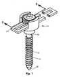
- FIG. 1is a perspective view of a spinal fixation system
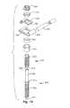
- FIG. 2is an exploded perspective view of the spinal fixation system of FIG. 1 ;
- FIG. 3is a sectional view of the spinal fixation system of FIG. 1 taken generally along line 3 - 3 of FIG. 1 ;
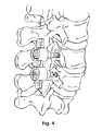
- FIG. 4is a perspective view of the spinal fixation system of FIG. 1 connected to a spine;
- FIG. 5is a perspective view of a spinal fixation system connected to a spine
- FIG. 6is an exploded perspective view of the spinal fixation system of FIG. 5 ;
- FIG. 7is a sectional view of the spinal fixation system of FIG. 5 taken generally along line 7 - 7 of FIG. 5 ;
- FIG. 8is a perspective view of the spinal fixation system of FIG. 5 connected to a spine;
- FIG. 9is a perspective view of a spinal fixation system
- FIG. 10is an exploded perspective view of the spinal fixation system of FIG. 9 ;
- FIG. 11is a sectional view of the spinal fixation system of FIG. 9 taken generally along line 11 - 11 of FIG. 9 ;
- FIG. 12is a perspective view of the spinal fixation system of FIG. 9 connected to a spine;
- FIG. 13is a perspective view of a spinal fixation system
- FIG. 14is an exploded perspective view of the spinal fixation system of FIG. 13 ;
- FIG. 15is a sectional view of the spinal fixation system of FIG. 13 taken generally along line 15 - 15 of FIG. 13 ;
- FIG. 16is a perspective view of the spinal fixation system of FIG. 13 connected to a spine;
- FIG. 17is a perspective view of a pedicle screw and drill assembly
- FIG. 18is a perspective view of the pedicle screw and drill assembly of FIG. 17 as assembled for use;
- FIG. 19is a sectional view of the pedicle screw and drill assembly of FIG. 18 ;
- FIG. 20is a perspective view of the pedicle screw and drill assembly of FIG. 18 positioned for use on a spine;
- FIG. 21is a perspective view of the pedicle screw and drill assembly of FIG. 20 after connection of the pedicle screw to the spine;
- FIG. 22is a perspective view of a pedicle screw and associated drill assembly connected to a spine
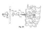
- FIG. 23is an exploded perspective view of the components of a spinal fixation system
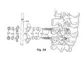
- FIG. 24is an exploded perspective view of a spinal fixation system
- FIG. 25is a perspective view of the spinal fixation system of FIG. 24 with the components assembled;
- FIG. 26is a perspective view of a bone graft implant
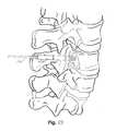
- FIG. 27is a perspective view of a bone graft implant in use as part of a spinal fixation system
- FIG. 28is a perspective view of a spinal fixation system
- FIG. 29is an exploded perspective view of the spinal fixation system of FIG. 28 ;
- FIG. 30is a partial sectional view of the spinal fixation system of FIG. 28 taken generally along line 30 - 30 of FIG. 28 ;
- FIG. 31is a partial sectional view of the spinal fixation system of FIG. 28 showing the pedicle screw secured at an angle;
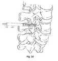
- FIG. 32is a perspective view of a spinal fixation system
- FIG. 33is an exploded perspective view of the spinal fixation system of FIG. 32 ;
- FIG. 34is a sectional view of the spinal fixation system of FIG. 32 taken generally along line 34 - 34 of FIG. 32 ;
- FIG. 35is a partial perspective view of the spinal fixation system of FIG. 32 taken generally along line 35 - 35 of FIG. 32 ;
- FIG. 36is a partial sectional view of the spinal fixation system of FIG. 32 showing the pedicle screw secured at an angle;
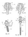
- FIG. 37is a perspective view of a spinal fixation system
- FIG. 38is an exploded perspective view of the spinal fixation system of FIG. 37 ;
- FIG. 39is a partial sectional view of the spinal fixation system of FIG. 37 showing the pedicle screw secured at an angle;
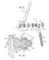
- FIG. 40is a perspective view of a spinal fixation system
- FIG. 41is an exploded perspective view of the spinal fixation system of FIG. 40 ;
- FIG. 42is a partial sectional view of the spinal fixation system of FIG. 40 taken generally along line 42 - 42 of FIG. 40 .
- a spinal fixation systemin an exemplary embodiment of the invention, includes a bone anchoring element or bone screw, shown as pedicle screw 10 .
- the pedicle screw 10is coupled to a fixation element or linking device, shown as fixation plate 12 , via a coupling mechanism 14 .
- fixation plate 12may be inserted through a pedicle and into a vertebra and linked to other pedicle screws by the fixation plate 12 .
- the length of the fixation plate 12is chosen to accommodate the total distance between the pedicle screws that are linked together.
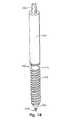
- the pedicle screw 10includes a threaded portion 16 and a non-threaded upper portion, shown as post 18 .
- a tip 20may be configured to be self-drilling and a shoulder or flange 22 may extend from the screw 10 between the post 18 and threaded portion 16 .
- an engagement mechanism for a screwdriver or drillshown as recess 24 , may be utilized.
- a receiver 26includes a pair of wall portions 28 that together form a U-shaped receiver sized to receive fixation plate 12 .
- the internal side of wall portions 28may be threaded to engage with other instrumentation.
- the wall portions 28extend upwardly from base 30 .
- collar 32has a threaded interior portion and a shoulder 34 that is sized to rest upon base 30 .
- a collet 36includes a number of compressible arms 38 intended to engage with pedicle screw 10 upon assembly.
- a lower set screw 40has a head 42 that may be configured to be grasped by a tool, such as the hex-head configuration shown in FIG. 2 .
- a threaded portion 44is configured to engage with the internal threads of the collar 32 during assembly.
- a pair of retaining rings 46 , 48engage either side of fixation plate 12 , the lower retaining ring 46 resting upon collar 32 and the upper retaining ring 48 compressed between the fixation plate 12 and an upper set screw 50 .
- the upper set screw 50has a threaded portion 52 intended to engage with the threaded interior side of wall portions 28 of the receiver 26 upon assembly.
- the upper set screw 50may have a head configuration designed to be engaged by a wrench or other tightening tool.
- each of the components forming the coupling mechanismhas an interior channel or aperture configured to allow the components to be placed upon and encircle the post 18 .
- the collet 36is placed into collar 32 , the outer diameter of the collet 36 being greater along a portion of the longitudinal axis of collet 36 than the interior diameter of collar 32 , as shown in FIG. 3 .
- the lower set screw 40may then be threaded into collar 32 , thus engaging collet 36 and pushing collet 36 downward through the collar 32 until the compressible arms 38 are forced to grip and be secured to post 18 . Engagement of the post 18 by the collet 36 locks the collet 36 and the other components of the coupling mechanism into place relative to the pedicle screw 10 for fixation to the fixation plate 12 .
- the collet 36may be locked onto post 18 at any position along the longitudinal axis of post 18 , affording flexibility in the placement of the coupling mechanism components.
- the colletmay engage with the threaded portion of the pedicle screw.
- the flexibility in placement of the colletis important due to the variability in placement of the pedicle screw 10 depending on the anatomy of the patient's spine.
- the recess 24extends into the pedicle screw 10 to create a keyed portion of a passage 54 that extends the length of the pedicle screw 10 .
- the keyed portionmay serve as an engagement point for a driver as discussed above.
- FIG. 4the embodiment of the spinal fixation system shown in FIGS. 1-3 is shown installed into a patient's spine.
- the pedicle screws 10may be individually installed prior to the installation of the fixation plate 12 across the multiple pedicle screws 10 .
- the fixation plate 12is centered upon the line of pedicle screws 10 as opposed to the offset configuration seen with other fixation system embodiments.
- a fixation systemin accordance with another embodiment of the invention is shown and includes a bone coupling element or bone screw, shown as pedicle screw 100 , a linking device, shown as fixation rod 102 , and a coupling mechanism (generally shown as coupling mechanism 104 ) used to connect the pedicle screw 100 and fixation rod 102 together.
- the fixation rod 102provides similar functionality to the fixation plate 12 .
- pedicle screw 100includes a threaded portion 106 and a non-threaded post 108 .
- a recess 110is provided at the top of pedicle screw 100 in order to provide an engagement point for a drill or screwdriver.
- the triangle-shaped recessis exemplary only and may take various forms such as a slot or a hexagonal recess depending on the type of tool utilized for turning the pedicle screw.
- a receiver 112includes a pair of wall portions 114 extending upwardly from base 116 .
- a collar 118is integrally formed as part of the receiver 112 .
- the U-shaped configuration of the upwardly extending wall portions 114 and base 116is suited to receive and be attached to fixation rod 102 .
- a collet 120is sized to fit into the collar 118 and be pressed downward by a set screw 122 , the set screw 122 having a threaded portion 124 such that it may be screwed into the collar 118 .
- a nut 126is sized to be connected to a threaded portion 128 of the receiver 112 .
- the fixation rod 102is attached to the pedicle screw 100 by the various components of the coupling mechanism.
- the receiver 112is first placed upon the post 108 , followed by insertion of the collet 120 and the set screw 122 into the receiver 112 and collar 118 . Tightening the set screw 122 forces the collet 120 downward through the narrowing passageway of the collar 118 such that the compressible arms of the collet 120 are forced inward to grip and fasten to the post 108 at the desired point on the post 108 .
- the receiver 112is also fixed into place and ready for placement of the fixation rod 102 into the U-shaped channel of the receiver 112 , followed by the addition of the nut 126 to secure the fixation rod 102 into place, completing the installation of the fixation hardware for a particular vertebra.
- the pedicle screw 100is first installed into the vertebra by screwing the pedicle screw 100 into place, with the use of the self-drilling configuration of pedicle screw 100 or other installation methods known in the art.
- Recess 110may be used as the engagement point for the pedicle screw 100 for drilling the pedicle screw into the chosen vertebra.
- the pedicle screw 100may be cannulated as shown by the passage 130 extending the length of the pedicle screw 100 with an opening at both the proximal end and the distal end of the pedicle screw 100 .
- FIG. 8the spinal fixation system depicted in FIGS. 5-7 is shown installed into a patient's spine.
- different pedicle screws 100may protrude from the spine at different heights depending on anatomical variations that may affect how deep the pedicle screw 100 is drilled into particular vertebra.
- the use of the collet 120 that may engage the pedicle screw 100 at various heightsis useful to permit the fixation rod 102 to be utilized in connecting the various pedicle screws 100 together.
- a spinal fixation systemaccording to another embodiment of the invention is shown and includes a bone coupling element, shown as pedicle screw 200 , a linking device, shown as fixation plate 202 , and a coupling mechanism, the components generally shown as coupling mechanism 204 .
- the pedicle screw 200is similar to the pedicle screws described with respect to other embodiments of the invention, and includes a threaded portion 206 and a non-threaded portion, shown as post 208 .
- a recess 210provides an interface for a tool or drill used to drill the pedicle screw 200 through a pedicle and into a vertebral body.
- a collet 214has an elongated design with an inner aperture designed to be fitted over post 208 , a set of compressible arms 216 designed to engage the pedicle screw 200 , and a threaded portion 218 .
- a collar 212is designed to interface with the compressible arms 216 .
- a pair of retaining rings 220 , 222provide an engagement point for the coupling mechanism with the fixation plate 202 .
- a fastening deviceshown as nut 224 , has threads configured to engage with the threaded portion 218 of the collet 214 .
- the collet 214 , collar 212 , and retaining ring 220are placed over the post 208 after installation of the pedicle screw 200 into the chosen vertebra.
- the post 208 upon which the various components of the coupling mechanism are placedprovides a guide and retaining function during assembly of the coupling mechanism to ease the attachment of the fixation plate 202 .
- the retaining ring 222 and nut 224are placed into position over the fixation plate 202 . Tightening of the nut 224 performs two functions. First, the nut 224 engages the threads of the collet 214 and pulls the compressible arms 216 up into the collar 212 in order to depress the compressible arms 216 into the post 208 , thereby locking the collet 214 onto the pedicle screw 200 . Further, the nut 224 locks the fixation plate 202 relative to the pedicle screw 200 by compressing the fixation plate 202 between the retaining rings 220 , 222 . A passage, shown as passage 226 extends the length of the pedicle screw 200 generally extending from the recess 210 .
- FIGS. 9-12requires only one component to be screwed into place, the nut 224 , which connects both the fixation plate 202 and the collet 214 to the pedicle screw 200 .
- the rest of the components of the coupling mechanism 204slide into place over the post 208 . Reducing the number of components that must be screwed together in the assembly of the spinal fixation system is advantageous as cross-threading of components that are screwed together is a problem encountered in surgery and reducing the number of components that must be screwed together addresses that issue.
- only requiring one pair of components to be screwed together per pedicle screwmay reduce the time necessary to assemble the spinal fixation system, thereby reducing the overall time required for the operation.
- FIG. 12the invention shown in FIGS. 9-11 is shown as installed into a spine, with two pedicle screws 200 shown for exemplary purposes although a greater number of pedicle screws 200 may be utilized, depending on the number of vertebrae to be fixed to one another.
- the fixation plate 202may be of various lengths depending on the number of pedicle screws 200 used. Because the collet 214 may engage the pedicle screw 200 at various points, variations in the heights of the installed pedicle screws 200 may be addressed in order to result in a continuous height of the fixation plate 202 by simply varying the points of engagement of the coupling mechanism 204 on different pedicle screws 200 .
- a spinal fixation systemincludes a bone-coupling element, shown as pedicle screw 300 , a fixation element or linking device, shown as fixation rod 302 , and a coupling mechanism, generally shown as coupling mechanism 304 .
- the pedicle screw 100includes a threaded portion 306 and a non-threaded portion shown as post 308 .
- the threaded portion 306is bounded by a distal tip 310 and a flange 312 .
- a recess 314extends into the post 308 for engagement by a tool or drill.
- a collet 318has an interior channel sized to fit over the post 308 .
- the collet 318includes a threaded portion 322 and a number of compressible arms 320 .
- a collar 316is sized to fit over the collet 318 .
- a receiver for the fixation rod 302includes a pair of plates, shown as lower portion 328 and upper portion 330 .
- the platesare hinged so that the upper portion 330 is pivotally attached to the lower portion 328 .
- the lower portion 328includes a hook 334 for engagement with the fixation rod 302 and the upper portion 330 includes an engagement arm 332 that is used to lock the fixation rod 302 into place.
- a pair of retaining rings 324 , 326are disposed on either side of the receiver and a fastening device, shown as nut 336 , is configured to secure the entire coupling mechanism together by threading onto collet 318 .
- the coupling mechanismis secured to the pedicle screw 300 in a similar fashion to that described with respect to the embodiment depicted in FIGS. 9-12 via the tightening of nut 336 onto collet 318 , thereby pulling the compressible arms 320 up into the collar 316 , thereby fixing the collet 318 into place at the selected height upon pedicle screw 300 .
- Engagement with the fixation rod 302however is handled differently by using the components of the receiver to attach the coupling mechanism to the fixation rod 302 with the fixation rod 302 offset from the longitudinal axis of the pedicle screw 300 . Further referring to FIG.
- the fastening device or nut 336performs two coupling functions that require at least two fastening components in other designs.
- the various components of the coupling mechanismare stacked onto the pedicle screw 300 using the post 308 as a guide after installing the pedicle screw 300 into the bone.
- the components of the receiverare configured to be installed on the post 308 along a range of positions offset from the longitudinal axis of the pedicle screw 300 to allow for some variability in the angle of the pedicle screw 300 after installation into the chosen vertebra. Further, like the earlier described embodiments, the coupling mechanism may be adjusted along the longitudinal axis of the pedicle screw 300 to account for variability in the height of the installed pedicle screw 300 .
- the spinal fixation system shown in FIGS. 13-15may be installed in the spine with the fixation rod 302 oriented on either side of the pedicle screws 300 by changing the position of the receiver lower portion 328 and upper portion 330 .
- additional pedicle screws 300may be installed in a line with a fixation rod 302 having the appropriate length to connect the pedicle screws 300 .
- a pedicle screw 400may be used in conjunction with a driver, shown as drill 414 , and holding device 430 .
- the pedicle screw 400includes a threaded portion 402 , a non-threaded post 404 , a tip 406 , a flange or ridge 410 , and a recess 412 .
- the drill 414includes a shaft 416 sized to fit within a passage 408 (see FIG. 19 ), a portion having cutting edges 418 , and a drill tip 420 . Referring to FIGS.
- the pedicle screws shown in various embodiments of the inventionare cannulated to include passages 54 , 130 , 226 , and 338 to accommodate drills such as drill 414 .
- the drill 414may function as a drill and as a driver for turning the screw.
- the term “driver”is intended to generically refer to a drill or turning tool or a tool having both functions.
- a keyed segment 422 of the drillis shaped to lock into recess 412 so that when the drill 414 is rotated, the pedicle screw 400 is also rotated.
- An expanded segment 424is sized to rest upon the top of post 404 , and has an outer diameter that is the same as that of post 404 in a preferred embodiment.
- An upper keyed segment 426provides an interface for a drill or other turning tool used to turn the drill 414 and the pedicle screw 400 .
- a holding device 430is shown as having a cylindrical shape and an attachment mechanism, shown as a number of prongs 432 , extending from the bottom of the holding device 430 and intended to snap over the ridge 410 to connect the holding device 430 to the pedicle screw 400 .
- the top of the holding device 430may be shaped to engage expanded segment 424 to lock the drill 414 into place in the pedicle screw 400 .
- the pedicle screw 400 , drill 414 , and holding device 430create an efficient tool for drilling the pedicle screw into a selected vertebra.
- the drill tip 420extends from the distal opening of the passage in the pedicle screw at the pedicle screw tip 406 to aid in the insertion of the pedicle screw 400 .
- the smaller diameter cutting edges 418 and sharp cutting tip 420may be desired by a surgeon when inserting the pedicle screw 400 to provide a more accurate placement and initial drilling point for the pedicle screw 400 , eliminating the necessity of first drilling a pilot hole and utilizing a guide wire to guide the pedicle screw.
- the holding device 430aids in the manipulation of the pedicle screw 400 and drill 414 by preventing the drill 414 from disengaging from the pedicle screw 400 during the insertion process.
- the drill 414 and holding device 430may be assembled together with the pedicle screw 400 prior to connecting the pedicle screw 400 to the spine and may be assembled by sliding the components together and snapping the holding device 430 onto the pedicle screw 400 without having to screw various components together.
- the assembled device depicted in FIG. 18may be utilized to drill the pedicle screw 400 into a chosen location in the spine utilizing the drill 414 in combination with the pedicle screw 400 .
- the drill tip 420aids in selecting a precise location for drilling the hole for the pedicle screw 400 .
- the holding device 430may be removed from the pedicle screw 400 by disengaging the prongs 432 , which in a preferred embodiment may be disengaged by pulling the holding device 430 away from the pedicle screw 400 .
- the drill 414remains. In a preferred embodiment, the drill may be removed from the pedicle screw 400 by pulling the keyed segment 422 out of the recess 412 . However, the user may elect to leave the drill 414 in place (or replace the drill 414 with another driver configured to be inserted into the passage 408 ) during assembly of the coupling mechanism as described below.
- the drill 414may be utilized in conjunction with a pedicle screw after installation of the pedicle screw to aid in the installation of various coupling components.
- the components of the coupling mechanism 304 shown in FIGS. 13-16are shown for exemplary purposes only. A similar approach may be utilized with the other coupling mechanisms and components shown with respect to the spinal fixation systems described in other embodiments of the invention.
- the drill 414including upper keyed segment 426 and expanded segment 424 , is sized to provide a guide for the coupling components utilized to attach the pedicle screw 300 to the fixation rod 302 .
- a surgeonmay elect to leave the drill 414 in place and utilize the drill 414 to serve as a guide for installation of the collet 318 , collar 316 , retaining ring 324 , receiver lower portion 328 , and upper portion 330 , retaining ring 326 , and nut 336 .
- the surgeonmay remove the drill 414 and insert a similarly configured driver into the screw to function as the guide.
- use of the drill 414 as a guide for the coupling componentsmay be especially useful because a small percutaneous aperture may be made for each installed pedicle screw, and the drill 414 may extend out of the patient's body to aid in placement of the coupling components. Without the aid of the drill 414 as a guide in minimally invasive surgical approaches, placement of the components directly onto the post 308 may be difficult due to the small size of the percutaneous aperture and obstructed visual access.
- the drill 414may be left in place in multiple pedicle screws 300 after the installation of each pedicle screw 300 .
- Such an approachrequires the use of multiple drills 414 so that during a surgical operation, each pedicle screw 300 may be installed with a separate drill 414 , the drill 414 left into place for installation of coupling components for each pedicle screw 300 .
- FIG. 24depicts two pedicle screws 300 requiring coupling components for exemplary purposes but the concept may be utilized with any number of pedicle screws.
- the individual drills 414may be removed by pulling the drills out of the pedicle screws, leaving the installed components (including the pedicle screws 300 ) in place.
- One reason for the utilization of a separate drill 414 which is removable from the installed fixation systemis that the surgeon may not wish to utilize components of a fixation system that include a permanently installed sharp cutting tip.
- the spinal fixation systemincludes a mechanism for inserting bone graft material as part of a spinal fusion procedure, shown as bone graft implant 500 .
- the bone graft implant 500includes a reservoir, shown as a nylon or fiber mesh bag 502 , having a pair of end caps 504 .
- a number of apertures, shown as grommets 506may be placed in the bag 502 on both sides of the bag 502 to permit installation of the bag 502 over a number of pedicle screws.
- the bag 502may be filled with a bone graft material and utilized to enhance spinal fusion.
- the bone graft implant 500may be placed over a number of pedicle screws 508 prior to installation of a linking device, shown as fixation plate 510 , and the associated coupling mechanism.
- a linking deviceshown as fixation plate 510
- the pedicle screws, fixation plate, and coupling mechanismare similar to the components shown in the spinal fixation system embodiment described above with respect to FIGS. 9-12 .
- the pedicle screws 508may be installed into the selected vertebrae, followed by installation of the bone graft implant 500 , which has already been filled with bone graft material, over the posts of the pedicle screws 508 .
- the grommets 506provide a mechanism for maintaining the placement of the bone graft implant 500 in the proper location and also provides an effective guide mechanism where visual access is impaired because the grommets 506 may be placed over the free posts of the pedicle screws 508 and glided into position along the pedicle screws.
- the bone graft implant 500may be inserted into the patients body through one aperture, with the placement of a grommet 506 over the post of the pedicle screw, and then threaded under the patient's skin up to the next pedicle screw for placement of the next grommet, and so forth for the number of pedicle screws that are being utilized.
- a stringmay be threaded between the adjacent pedicle screws to aid in the pulling of the bone graft implant 500 between the access ports.
- a spinal fixation systemaccording to another embodiment of the invention is shown and includes a bone coupling element, shown as pedicle screw 600 , a linking device or fixation element, shown as fixation rod 602 , and a coupling mechanism, generally shown as coupling mechanism 604 .
- the pedicle screw 600is similar to the pedicle screws described with respect to other embodiments of the invention and includes a threaded portion 606 and a non-threaded portion, shown as post 608 .
- Other pedicle screw designsmay also be used with the coupling mechanism 604 .
- a recess 610provides an interface for a tool or drill used to drill the pedicle screw 600 through a pedicle and into a vertebral body. Similar to the other pedicle screws described herein, passage 622 extends the length of the pedicle screw 600 .
- a pedicle screw securing deviceshown as collet 614 , includes an internal aperture designed to be fitted over post 608 , a set of compressible arms 616 designed to engage the pedicle screw 600 , and a threaded portion 618 .
- the pedicle screw securing devicemay take other forms such as a Morse Taper or a tongue and groove configuration.
- the coupling mechanismincludes a body 612 having two passages, one sized to receive the fixation rod 602 and the other sized to receive the collet 614 , pedicle screw 600 , and an engagement or fastening device, shown as split ring 620 . While the two passages shown in FIG. 29 extend orthogonally to one another, the two passages may extend in other directions relative to one another in other embodiments of the invention. The two passages are connected by an aperture allowing the split ring 620 to act upon the fixation rod 602 . In other embodiments, the split ring may be replaced by a cam or sliding pin.
- the split ring 620includes interior threads configured to mate with the external threads of the collet 614 .
- the collet 614includes an engagement design at the top of the collet that is engaged by a tightening tool, such as a wrench having an interlocking design, that may be used to rotate the collet 614 to secure the collet 614 into the split ring 620 .
- a tightening toolsuch as a wrench having an interlocking design
- the collet 614 , split ring 620 , and body 612are placed over the post 608 after installation of the pedicle screw 600 into the chosen vertebra.
- the various components of the coupling mechanismare slidable with respect to the fixation rod 602 and the post 608 prior to tightening to allow for proper adjustment of the various components.
- the collet 614may be screwed into the split ring 620 .
- the colletmay engage the fastening mechanism in different ways such as through the use of splines.
- the split ring 620acts as a fastening device by performing two functions. First, rotation of the collet 614 into the split ring 620 forces the split ring 620 outward such that the outer surface of the split ring 620 engages the fixation rod 602 , thus securing the fixation rod 602 with respect to the body 612 , functioning as a fixation element securing device. Second, the split ring 620 forces the compressible arms 616 of the collet 614 onto the post 608 , thus securing the pedicle screw 600 to the body 612 .
- the coupling mechanism 604is secured to both the pedicle screw 600 and fixation rod 602 by the tightening of one fastening mechanism, the collet 614 . Accordingly, the design is intended to simplify the process of coupling the fixation rod 602 to the pedicle screw 600 by reducing the number of actions necessary to accomplish this task. Further, the component that is acted upon to accomplish the fastening of the coupling mechanism, the collet 614 , is centered along the longitudinal axis of the pedicle screw 600 .
- a small percutaneous aperturemay be opened in the patient for installation of the various pedicle screws. Alignment of the fastening mechanism for the coupling mechanism with the longitudinal axis of the pedicle screw allows the surgeon to more easily accomplish the attachment of the coupling mechanism. In the embodiment of FIGS. 28-31 , the surgeon may insert a tightening instrument through the percutaneous aperture in order to rotate the collet 614 into the split ring 620 .
- a spinal fixation system including a fastening mechanism this is substantially offset from the longitudinal axis of the pedicle screwpresents additional challenges for the surgeon because the fastening mechanism may not be easily accessible through the aperture used in minimally invasive surgery.
- the passage in the body 612 that receives the pedicle screw 600is sized to permit variations in the angle of the pedicle screw 600 with respect to the body 612 .
- a screw angle of up to twenty degreesmay be allowed by the body 612 while still allowing the pedicle screw 600 to be positively secured to the fixation rod 602 by the coupling mechanism.
- Changes in the orientation of the split ring 620are permitted due to the curved interior profile of the passage in the body 612 matching the curved exterior profile of the split ring 620 , allowing the split ring 620 to be positively secured at various angles with respect to the body 612 .
- FIGS. 28-31may be installed into a spine in a similar fashion as shown with respect to the other spinal fixation system embodiments described herein.
- a spinal fixation systemincludes a pedicle screw 700 , a coupling mechanism 702 , and a fixation element, shown as fixation rod 722 .
- a pedicle screw securing deviceshown as collet 704 , has a number of compressible arms 706 and includes an aperture sized to receive a post 716 of the pedicle screw 700 .
- a receiverincludes a lower portion 708 and an upper portion 710 , both having apertures sized to fit over the collet 704 .
- the lower portion 708includes a fixation element receiving aperture, shown as rod aperture 712
- the upper portion 710includes a fixation element receiving aperture, shown as rod aperture 714 , both rod apertures 712 , 714 sized to receive fixation rod 722 (see FIG. 32 ).
- a fastening mechanism, shown as nut 718includes interior threads matching a threaded portion 720 of the collet 704 .
- the various components of the coupling mechanism 702may be placed over the pedicle screw 700 , using the post 716 as a guide, prior to fastening the coupling mechanism 702 to the pedicle screw 700 and fixation rod 722 .
- the nut 718may be tightened onto the collet 704 , drawing the compressible arms 706 up into the lower portion 708 of the receiver, forcing the arms 706 against the post 716 , thereby securing the collet 704 at the selected height upon pedicle screw 700 .
- the arms 706have flat portions or flats 724 that engage with the lower portion 708 , preventing the collet 704 from rotating along with the nut 718 during the tightening process. Tightening of the nut 718 onto the threaded portion 720 also secures the coupling mechanism to the associated fixation rod 722 because the compressible arms 706 pull the lower portion 708 into the upper portion 710 , thereby shifting the alignment of the rod apertures 712 , 714 sufficiently to create an offsetting grip upon the fixation rod 722 , the receiver thereby functioning as a fixation element securing device.
- the embodiment shown in FIGS. 32-36includes a coupling mechanism 702 that may be secured to both a pedicle screw and a linking device via a one-step procedure, in this case the tightening of nut 718 .
- the nut 718is oriented along the longitudinal axis of pedicle screw 700 , it may be accessed for fastening of the coupling mechanism through the small aperture used to insert the pedicle screw 700 in minimally invasive surgery.
- the complimentary curved profiles of the lower portion 708 , upper portion 710 , and nut 718allow for variability in the angle of the pedicle screw 700 within the receiver.
- the rounded portions of the arms 706 between the flats 724permit the collet 704 to be secured at an angle as shown in FIG. 36 .
- a spinal fixation systemincludes a pedicle screw 800 and a coupling mechanism 802 intended to couple the pedicle screw 800 to a fixation element or linking device such as a fixation rod (not shown).
- the pedicle screw 800includes a post 804 that extends through the components of the coupling mechanism 802 including a receiver 806 , a collar 812 , a split ring 814 , and a fastening mechanism, shown as nut 816 .
- the receiver 806includes a receiver loop 808 adapted to receive a fixation rod, and a pair of receiver arms 810 , each having an aperture sized to receive the collar 812 and post 804 , and providing enough space for the post 804 to extend through the receiver 806 at an angle (see FIG. 39 ).
- the collar 812includes a set of threads on the exterior thereof adapted to mate with corresponding internal threads of the nut 816 .
- the nut 816has a spherical internal radius at an upper portion thereof allowing variability in the angle of the split ring 814 and the pedicle screw 800 within the coupling mechanism 802 . Tightening of the nut 816 onto the collar 812 accomplishes two functions. First, the nut 816 forces the receiver arms 810 together, thereby securing the receiver loop 808 to a fixation rod (not shown) situated therein. Second, the nut 816 forces the split ring 814 downward into the collar 812 , which collapses the split ring 814 onto the post 804 , thus securing the post 804 into place.
- the single action of tightening the nut 816accomplishes the functions of securing the pedicle screw 800 and the associated fixation element.
- the split ring 814acts as a pedicle screw securing device and the loop 808 acts as a fixation element securing device.
- the pedicle screw 800is shown as secured by the coupling mechanism 802 at an angle relative to the collar 812 . As is apparent from FIG. 39 , the angle is variable to permit a degree of flexibility in the attachment of the pedicle screw 800 to the coupling mechanism 802 . As discussed above with respect to certain other embodiments of the invention, the fastening device, shown as the nut 816 , is located on top of the pedicle screw 800 , permitting access to the fastening device through the percutaneous aperture used to insert the pedicle screw 800 into the spine during a minimally invasive surgical procedure.
- a spinal fixation systemincludes a pedicle screw 900 , a fixation element, shown as a fixation rod 902 , and a coupling mechanism, generally shown as coupling mechanism 904 .
- the pedicle screw 900includes a threaded portion 906 and a post 908 that extends through a portion of the coupling mechanism 904 .
- the coupling mechanism 904includes a fixation element securing device, shown as rod receiver 910 , with an aperture configured to receive the fixation rod 902 .
- the rod receiver 910includes a rod receiver loop 916 that encircles the fixation rod 902 , and works in conjunction with a rod receiver base 918 that has a rounded channel configured to receive the fixation rod 902 .
- the rod receiver loop 916 and the rod receiver base 918combine to securely attach the coupling mechanism 904 to the fixation rod 902 .
- a screw receiver 912is configured similarly to the rod receiver 910 and includes a screw receiver loop 920 and a screw receiver base 922 that combine to serve as an attachment point for the pedicle screw 900 .
- a screw receiver nut 924has interior threads that mate with exterior threads on the screw receiver loop 920 in order to pull the screw receiver loop 920 into the screw receiver base 922 to fasten the pedicle screw 900 to the coupling mechanism 904 when the screw receiver nut 924 is tightened.
- a rod receiver nut 926contains interior threads that mate with exterior threads on the rod receiver loop 916 in order to pull the rod receiver loop into the rod receiver base 918 , thus securing the fixation rod 902 to the coupling mechanism 904 .
- the rod receiver components and the screw receiver componentsare attached to one another via a coupling protrusion 914 extending from the screw receiver loop 920 into a receiving area defined by the rod receiver nut 926 and the rod receiver loop 916 .
- the coupling protrusion 914is an integral extension of the screw receiver loop 920 .
- the coupling protrusion 914is shaped to permit variability in the angle of attachment between the screw receiver components and the rod receiver components so that variability in the angle of the pedicle screw 900 is permitted.
- the coupling mechanism 904 componentsare secured to the pedicle screw 900 and fixation rod 902 by rotating the screw receiver nut 924 and rod receiver nut 926 .
- the screw receiver nut 924 and the rod receiver nut 926are rotated in opposite directions to secure the coupling mechanism 904 .
- the various spinal fixation or instrumentation systems described herein as exemplary embodiments of the inventionmay be utilized in the performance of spinal fusion procedures using a streamlined method that is intended to simplify and shorten conventional spinal fusion procedures.
- imaging of the patientmay be utilized to determine the number of pedicle screws that will be linked together as part of the spinal fusion procedure.
- an image guidance systemmay be utilized as part of the procedure to aid in the placement of the various components.
- an entry siteis created in the patient along the portion of the spine into which the pedicle screws will be inserted.
- individual entry portsmay be utilized for implantation of individual pedicle screws.
- the pedicle screws described herein that are self drillingmay be drilled directly through the pedicles and into the vertebra.
- the drillmay be inserted into the pedicle screw, using the holding device to hold the drill in place, and utilized to drill into the pedicle simultaneously with the pedicle screw.
- conventional proceduresmay be utilized, including the pre-drilling and tapping of a hole in the pedicle, utilizing a Kirschner wire or guide wire as appropriate.
- the cannulated pedicle screws described hereinare useful for incorporating the drill or for the use of a guide wire as desired by the surgeon.
- the coupling mechanismis then utilized to connect the pedicle screws to a linking device, such as a fixation rod or plate as shown and described herein with respect to several exemplary embodiments.
- a linking devicesuch as a fixation rod or plate as shown and described herein with respect to several exemplary embodiments.
- multiple drillsmay be utilized to aid in the installation of the coupling components and the linking device may be threaded beneath the patient's skin between the various pedicle screws that are being linked to each other.
- the transverse processesare decorticated prior to placing a bone graft material to aid in the fusion of the adjacent vertebrae.
- Implantation of the bone graft materialis typically done prior to the insertion of the fixation rod or plate to attach the pedicle screws together.
- the bone graft implant shown in one embodiment in FIGS. 26 and 27may be utilized to insert the bone graft material.
- a drillsuch as drill 414
- the coupling componentsmay be placed on to the shaft of the drill to aid in the attachment of the fixation rod or plate.
- the drills that are utilizedmay then be removed from the pedicle screws.
- the installation of all the componentsmay be aided by a guidance system such as a fluoronavigation system, especially in the case of minimally invasive procedures requiring image guidance where visual access is obscured.
Landscapes
- Health & Medical Sciences (AREA)
- Orthopedic Medicine & Surgery (AREA)
- Life Sciences & Earth Sciences (AREA)
- Surgery (AREA)
- Neurology (AREA)
- Engineering & Computer Science (AREA)
- Biomedical Technology (AREA)
- General Health & Medical Sciences (AREA)
- Veterinary Medicine (AREA)
- Heart & Thoracic Surgery (AREA)
- Public Health (AREA)
- Animal Behavior & Ethology (AREA)
- Molecular Biology (AREA)
- Medical Informatics (AREA)
- Nuclear Medicine, Radiotherapy & Molecular Imaging (AREA)
- Oral & Maxillofacial Surgery (AREA)
- Dentistry (AREA)
- Cardiology (AREA)
- Transplantation (AREA)
- Vascular Medicine (AREA)
- Surgical Instruments (AREA)
Abstract
Description
Claims (20)
Priority Applications (1)
| Application Number | Priority Date | Filing Date | Title |
|---|---|---|---|
| US14/137,040US9168151B2 (en) | 2004-06-09 | 2013-12-20 | Spinal fixation system |
Applications Claiming Priority (4)
| Application Number | Priority Date | Filing Date | Title |
|---|---|---|---|
| US10/864,673US7938848B2 (en) | 2004-06-09 | 2004-06-09 | Spinal fixation system |
| US11/071,604US7744635B2 (en) | 2004-06-09 | 2005-03-03 | Spinal fixation system |
| US12/825,176US8617209B2 (en) | 2004-06-09 | 2010-06-28 | Spinal fixation system |
| US14/137,040US9168151B2 (en) | 2004-06-09 | 2013-12-20 | Spinal fixation system |
Related Parent Applications (1)
| Application Number | Title | Priority Date | Filing Date |
|---|---|---|---|
| US12/825,176ContinuationUS8617209B2 (en) | 2004-06-09 | 2010-06-28 | Spinal fixation system |
Publications (2)
| Publication Number | Publication Date |
|---|---|
| US20140135928A1 US20140135928A1 (en) | 2014-05-15 |
| US9168151B2true US9168151B2 (en) | 2015-10-27 |
Family
ID=35510239
Family Applications (4)
| Application Number | Title | Priority Date | Filing Date |
|---|---|---|---|
| US11/071,604Expired - LifetimeUS7744635B2 (en) | 2004-06-09 | 2005-03-03 | Spinal fixation system |
| US11/349,763AbandonedUS20060149245A1 (en) | 2004-06-09 | 2006-02-08 | Bone fixation system |
| US12/825,176Expired - LifetimeUS8617209B2 (en) | 2004-06-09 | 2010-06-28 | Spinal fixation system |
| US14/137,040Expired - LifetimeUS9168151B2 (en) | 2004-06-09 | 2013-12-20 | Spinal fixation system |
Family Applications Before (3)
| Application Number | Title | Priority Date | Filing Date |
|---|---|---|---|
| US11/071,604Expired - LifetimeUS7744635B2 (en) | 2004-06-09 | 2005-03-03 | Spinal fixation system |
| US11/349,763AbandonedUS20060149245A1 (en) | 2004-06-09 | 2006-02-08 | Bone fixation system |
| US12/825,176Expired - LifetimeUS8617209B2 (en) | 2004-06-09 | 2010-06-28 | Spinal fixation system |
Country Status (4)
| Country | Link |
|---|---|
| US (4) | US7744635B2 (en) |
| EP (1) | EP1761180A4 (en) |
| AU (1) | AU2005253980A1 (en) |
| WO (1) | WO2005122965A2 (en) |
Cited By (4)
| Publication number | Priority date | Publication date | Assignee | Title |
|---|---|---|---|---|
| US20190380745A1 (en)* | 2018-06-13 | 2019-12-19 | Nuvasive, Inc. | Rib Fixation Device and Related Methods |
| US11058437B2 (en) | 2018-03-29 | 2021-07-13 | Zimmer Biomet Spine, Inc. | Systems and methods for pedicle screw implantation using flexible drill bit |
| US11369474B2 (en) | 2017-07-17 | 2022-06-28 | Warsaw Orthopedic, Inc. | Bone implant having a mesh |
| US11464577B2 (en) | 2018-03-02 | 2022-10-11 | Mako Surgical Corp. | Tool assembly, systems, and methods for manipulating tissue |
Families Citing this family (157)
| Publication number | Priority date | Publication date | Assignee | Title |
|---|---|---|---|---|
| US7833250B2 (en) | 2004-11-10 | 2010-11-16 | Jackson Roger P | Polyaxial bone screw with helically wound capture connection |
| US7862587B2 (en) | 2004-02-27 | 2011-01-04 | Jackson Roger P | Dynamic stabilization assemblies, tool set and method |
| US10729469B2 (en) | 2006-01-09 | 2020-08-04 | Roger P. Jackson | Flexible spinal stabilization assembly with spacer having off-axis core member |
| US8353932B2 (en) | 2005-09-30 | 2013-01-15 | Jackson Roger P | Polyaxial bone anchor assembly with one-piece closure, pressure insert and plastic elongate member |
| US10258382B2 (en) | 2007-01-18 | 2019-04-16 | Roger P. Jackson | Rod-cord dynamic connection assemblies with slidable bone anchor attachment members along the cord |
| US8292926B2 (en) | 2005-09-30 | 2012-10-23 | Jackson Roger P | Dynamic stabilization connecting member with elastic core and outer sleeve |
| US8876868B2 (en) | 2002-09-06 | 2014-11-04 | Roger P. Jackson | Helical guide and advancement flange with radially loaded lip |
| US7621918B2 (en) | 2004-11-23 | 2009-11-24 | Jackson Roger P | Spinal fixation tool set and method |
| US7377923B2 (en) | 2003-05-22 | 2008-05-27 | Alphatec Spine, Inc. | Variable angle spinal screw assembly |
| US8926670B2 (en) | 2003-06-18 | 2015-01-06 | Roger P. Jackson | Polyaxial bone screw assembly |
| US7776067B2 (en) | 2005-05-27 | 2010-08-17 | Jackson Roger P | Polyaxial bone screw with shank articulation pressure insert and method |
| US8366753B2 (en) | 2003-06-18 | 2013-02-05 | Jackson Roger P | Polyaxial bone screw assembly with fixed retaining structure |
| US7967850B2 (en) | 2003-06-18 | 2011-06-28 | Jackson Roger P | Polyaxial bone anchor with helical capture connection, insert and dual locking assembly |
| US7766915B2 (en) | 2004-02-27 | 2010-08-03 | Jackson Roger P | Dynamic fixation assemblies with inner core and outer coil-like member |
| US7527638B2 (en) | 2003-12-16 | 2009-05-05 | Depuy Spine, Inc. | Methods and devices for minimally invasive spinal fixation element placement |
| US11419642B2 (en) | 2003-12-16 | 2022-08-23 | Medos International Sarl | Percutaneous access devices and bone anchor assemblies |
| US7179261B2 (en) | 2003-12-16 | 2007-02-20 | Depuy Spine, Inc. | Percutaneous access devices and bone anchor assemblies |
| US7678137B2 (en) | 2004-01-13 | 2010-03-16 | Life Spine, Inc. | Pedicle screw constructs for spine fixation systems |
| US7993373B2 (en)* | 2005-02-22 | 2011-08-09 | Hoy Robert W | Polyaxial orthopedic fastening apparatus |
| US9451990B2 (en)* | 2004-02-17 | 2016-09-27 | Globus Medical, Inc. | Facet joint replacement instruments and methods |
| JP2007525274A (en) | 2004-02-27 | 2007-09-06 | ロジャー・ピー・ジャクソン | Orthopedic implant rod reduction instrument set and method |
| US8152810B2 (en) | 2004-11-23 | 2012-04-10 | Jackson Roger P | Spinal fixation tool set and method |
| US11241261B2 (en) | 2005-09-30 | 2022-02-08 | Roger P Jackson | Apparatus and method for soft spinal stabilization using a tensionable cord and releasable end structure |
| US7160300B2 (en) | 2004-02-27 | 2007-01-09 | Jackson Roger P | Orthopedic implant rod reduction tool set and method |
| US7744635B2 (en)* | 2004-06-09 | 2010-06-29 | Spinal Generations, Llc | Spinal fixation system |
| US8021398B2 (en)* | 2004-06-09 | 2011-09-20 | Life Spine, Inc. | Spinal fixation system |
| US7651502B2 (en) | 2004-09-24 | 2010-01-26 | Jackson Roger P | Spinal fixation tool set and method for rod reduction and fastener insertion |
| US8926672B2 (en) | 2004-11-10 | 2015-01-06 | Roger P. Jackson | Splay control closure for open bone anchor |
| WO2006057837A1 (en) | 2004-11-23 | 2006-06-01 | Jackson Roger P | Spinal fixation tool attachment structure |
| US9168069B2 (en) | 2009-06-15 | 2015-10-27 | Roger P. Jackson | Polyaxial bone anchor with pop-on shank and winged insert with lower skirt for engaging a friction fit retainer |
| US9216041B2 (en) | 2009-06-15 | 2015-12-22 | Roger P. Jackson | Spinal connecting members with tensioned cords and rigid sleeves for engaging compression inserts |
| US8444681B2 (en) | 2009-06-15 | 2013-05-21 | Roger P. Jackson | Polyaxial bone anchor with pop-on shank, friction fit retainer and winged insert |
| WO2006058221A2 (en) | 2004-11-24 | 2006-06-01 | Abdou Samy M | Devices and methods for inter-vertebral orthopedic device placement |
| US7901437B2 (en) | 2007-01-26 | 2011-03-08 | Jackson Roger P | Dynamic stabilization member with molded connection |
| US7678112B2 (en) | 2005-04-26 | 2010-03-16 | Warsaw Orthopedic, Inc. | Open dorsal adjusting connector |
| US9942511B2 (en) | 2005-10-31 | 2018-04-10 | Invention Science Fund I, Llc | Preservation/degradation of video/audio aspects of a data stream |
| US7850715B2 (en)* | 2005-04-29 | 2010-12-14 | Warsaw Orthopedic Inc. | Orthopedic implant apparatus |
| US8128665B2 (en)* | 2005-04-29 | 2012-03-06 | Warsaw Orthopedic, Inc. | Orthopedic implant apparatus |
| EP1749489B1 (en) | 2005-08-03 | 2010-11-17 | BIEDERMANN MOTECH GmbH | Bone anchoring device |
| JP5084195B2 (en) | 2005-08-03 | 2012-11-28 | ビーダーマン・モテーク・ゲゼルシャフト・ミット・ベシュレンクタ・ハフツング | Bone anchoring device |
| US8105368B2 (en) | 2005-09-30 | 2012-01-31 | Jackson Roger P | Dynamic stabilization connecting member with slitted core and outer sleeve |
| US7704271B2 (en) | 2005-12-19 | 2010-04-27 | Abdou M Samy | Devices and methods for inter-vertebral orthopedic device placement |
| ES2323008T3 (en)* | 2005-12-23 | 2009-07-03 | Biedermann Motech Gmbh | DEVICE OF DYNAMIC STABILIZATION OF BONES OR VERTEBRAS. |
| EP1971282A2 (en)* | 2006-01-10 | 2008-09-24 | Life Spine, Inc. | Pedicle screw constructs and spinal rod attachment assemblies |
| US20070173827A1 (en)* | 2006-01-20 | 2007-07-26 | Sdgi Holdings, Inc. | Adjustable connector for attachment to a rod in a medical application |
| US20070191844A1 (en)* | 2006-01-31 | 2007-08-16 | Sdgi Holdings, Inc. | In-series, dual locking mechanism device |
| WO2007121271A2 (en) | 2006-04-11 | 2007-10-25 | Synthes (U.S.A) | Minimally invasive fixation system |
| US7588593B2 (en)* | 2006-04-18 | 2009-09-15 | International Spinal Innovations, Llc | Pedicle screw with vertical adjustment |
| WO2007130007A1 (en)* | 2006-04-27 | 2007-11-15 | Warsaw Orthopedic, Inc. | Open dorsal adjusting connector |
| GB0610630D0 (en) | 2006-05-26 | 2006-07-05 | Ness Malcolm G | A bone fixation device |
| US10085780B2 (en) | 2006-05-26 | 2018-10-02 | Mark Richard Cunliffe | Bone fixation device |
| US20080021464A1 (en)* | 2006-07-19 | 2008-01-24 | Joshua Morin | System and method for a spinal implant locking assembly |
| JP5178717B2 (en)* | 2006-07-27 | 2013-04-10 | ジンテス ゲゼルシャフト ミット ベシュレンクテル ハフツング | Outrigger |
| US8388660B1 (en) | 2006-08-01 | 2013-03-05 | Samy Abdou | Devices and methods for superior fixation of orthopedic devices onto the vertebral column |
| US8062341B2 (en)* | 2006-10-18 | 2011-11-22 | Globus Medical, Inc. | Rotatable bone plate |
| FR2907663B1 (en)* | 2006-10-25 | 2009-05-15 | Hassan Razian | SPINAL OSTEOSYNTHESIS SYSTEM FOR CONNECTING AT LEAST TWO VERTEBRAL BODY PORTIONS |
| US8211110B1 (en)* | 2006-11-10 | 2012-07-03 | Lanx, Inc. | Minimally invasive tool to facilitate implanting a pedicle screw and housing |
| US8162990B2 (en) | 2006-11-16 | 2012-04-24 | Spine Wave, Inc. | Multi-axial spinal fixation system |
| WO2008065450A1 (en)* | 2006-11-29 | 2008-06-05 | Surgicraft Limited | Orthopaedic implants and prostheses |
| CA2670988C (en) | 2006-12-08 | 2014-03-25 | Roger P. Jackson | Tool system for dynamic spinal implants |
| US8475498B2 (en) | 2007-01-18 | 2013-07-02 | Roger P. Jackson | Dynamic stabilization connecting member with cord connection |
| US8366745B2 (en) | 2007-05-01 | 2013-02-05 | Jackson Roger P | Dynamic stabilization assembly having pre-compressed spacers with differential displacements |
| US8109975B2 (en)* | 2007-01-30 | 2012-02-07 | Warsaw Orthopedic, Inc. | Collar bore configuration for dynamic spinal stabilization assembly |
| US8926667B2 (en)* | 2007-02-09 | 2015-01-06 | Transcendental Spine, Llc | Connector |
| CA2679384C (en)* | 2007-02-28 | 2020-03-24 | Mass Modular Spine System | Tension fixation system |
| US10383660B2 (en) | 2007-05-01 | 2019-08-20 | Roger P. Jackson | Soft stabilization assemblies with pretensioned cords |
| US8979904B2 (en) | 2007-05-01 | 2015-03-17 | Roger P Jackson | Connecting member with tensioned cord, low profile rigid sleeve and spacer with torsion control |
| US8197517B1 (en) | 2007-05-08 | 2012-06-12 | Theken Spine, Llc | Frictional polyaxial screw assembly |
| CA2694010C (en)* | 2007-07-19 | 2015-04-21 | Synthes Usa, Llc | Clamps used for interconnecting a bone anchor to a rod |
| US8348976B2 (en) | 2007-08-27 | 2013-01-08 | Kyphon Sarl | Spinous-process implants and methods of using the same |
| US9629639B2 (en)* | 2007-08-28 | 2017-04-25 | DePuy Synthes Products, Inc. | Arrangement for securing instrument to bone |
| US20090105756A1 (en) | 2007-10-23 | 2009-04-23 | Marc Richelsoph | Spinal implant |
| US20090198289A1 (en)* | 2008-02-02 | 2009-08-06 | Manderson Easton L | Fortified cannulated screw |
| WO2009118033A1 (en)* | 2008-03-28 | 2009-10-01 | Bricon Ag | Vortex repositioning system |
| US8814935B2 (en)* | 2008-03-31 | 2014-08-26 | The Lonnie and Shannon Paulos Trust | Interference screw driver assembly and method of use |
| WO2009124196A2 (en)* | 2008-04-03 | 2009-10-08 | Life Spine, Inc. | Top loading polyaxial spine screw assembly with one step lockup |
| US8932332B2 (en)* | 2008-05-08 | 2015-01-13 | Aesculap Implant Systems, Llc | Minimally invasive spinal stabilization system |
| WO2009155523A1 (en)* | 2008-06-19 | 2009-12-23 | Life Spine, Inc. | Spinal rod connectors configured to retain spinal rods of varying diameters |
| AU2010260521C1 (en) | 2008-08-01 | 2013-08-01 | Roger P. Jackson | Longitudinal connecting member with sleeved tensioned cords |
| EP2484300B1 (en)* | 2008-09-05 | 2015-05-20 | Biedermann Technologies GmbH & Co. KG | Stabilization device for bones, in particular for the spinal column |
| US8147523B2 (en) | 2008-09-09 | 2012-04-03 | Warsaw Orthopedic, Inc. | Offset vertebral rod connector |
| US9603629B2 (en) | 2008-09-09 | 2017-03-28 | Intelligent Implant Systems Llc | Polyaxial screw assembly |
| EP2174608B1 (en)* | 2008-10-08 | 2012-08-01 | Biedermann Technologies GmbH & Co. KG | Bone anchoring device and stabilization device for bone parts or vertebrae |
| US8066746B2 (en) | 2008-12-23 | 2011-11-29 | Globus Medical, Inc. | Variable angle connection assembly |
| WO2010048606A1 (en)* | 2008-10-24 | 2010-04-29 | Globus Medical, Inc. | Variable angle connection assembly |
| EP2249725B1 (en)* | 2009-02-19 | 2015-06-10 | Ulrich GmbH & Co. KG | Device for stabilizing the spinal column |
| US20100249846A1 (en)* | 2009-03-25 | 2010-09-30 | Simonson Peter M | Variable height, multi-axial bone screw assembly |
| US9439685B2 (en)* | 2009-05-12 | 2016-09-13 | Bullard Spine, Llc | Multi-layer osteoinductive, osteogenic, and osteoconductive carrier |
| CN102497828B (en) | 2009-05-20 | 2015-09-09 | 斯恩蒂斯有限公司 | What patient installed retracts part |
| US9668771B2 (en) | 2009-06-15 | 2017-06-06 | Roger P Jackson | Soft stabilization assemblies with off-set connector |
| CN103826560A (en) | 2009-06-15 | 2014-05-28 | 罗杰.P.杰克逊 | Polyaxial Bone Anchor with Socket Stem and Winged Inserts with Friction Fit Compression Collars |
| US11229457B2 (en) | 2009-06-15 | 2022-01-25 | Roger P. Jackson | Pivotal bone anchor assembly with insert tool deployment |
| US8998959B2 (en) | 2009-06-15 | 2015-04-07 | Roger P Jackson | Polyaxial bone anchors with pop-on shank, fully constrained friction fit retainer and lock and release insert |
| USD746461S1 (en) | 2009-06-19 | 2015-12-29 | Life Spine, Inc. | Spinal rod connector |
| EP2485654B1 (en) | 2009-10-05 | 2021-05-05 | Jackson P. Roger | Polyaxial bone anchor with non-pivotable retainer and pop-on shank, some with friction fit |
| US8764806B2 (en) | 2009-12-07 | 2014-07-01 | Samy Abdou | Devices and methods for minimally invasive spinal stabilization and instrumentation |
| US8070781B2 (en) | 2010-01-12 | 2011-12-06 | Globus Medical, Inc. | Offset variable angle connection assembly |
| US8535318B2 (en) | 2010-04-23 | 2013-09-17 | DePuy Synthes Products, LLC | Minimally invasive instrument set, devices and related methods |
| US20110307015A1 (en)* | 2010-06-10 | 2011-12-15 | Spartek Medical, Inc. | Adaptive spinal rod and methods for stabilization of the spine |
| US10603083B1 (en) | 2010-07-09 | 2020-03-31 | Theken Spine, Llc | Apparatus and method for limiting a range of angular positions of a screw |
| US9084634B1 (en) | 2010-07-09 | 2015-07-21 | Theken Spine, Llc | Uniplanar screw |
| AU2011299558A1 (en) | 2010-09-08 | 2013-05-02 | Roger P. Jackson | Dynamic stabilization members with elastic and inelastic sections |
| TW201215369A (en)* | 2010-10-01 | 2012-04-16 | Metal Ind Res & Dev Ct | Spinal implant structure and method for manufacturing the same |
| EP2460484A1 (en)* | 2010-12-01 | 2012-06-06 | FACET-LINK Inc. | Variable angle bone screw fixation assembly |
| US8920475B1 (en) | 2011-01-07 | 2014-12-30 | Lanx, Inc. | Vertebral fixation system including torque mitigation |
| CA2827235A1 (en)* | 2011-02-14 | 2012-08-23 | The Royal Institution For The Advancement Of Learning / Mcgill Universit Y | Systems and methods for injecting fluid into bone and for inserting bone screws, and bone screws for same |
| US20120209385A1 (en)* | 2011-02-15 | 2012-08-16 | Joshua Michael Aferzon | Anterior intervertebral fusion with fixation system, device and method |
| US8672978B2 (en) | 2011-03-04 | 2014-03-18 | Zimmer Spine, Inc. | Transverse connector |
| US8992579B1 (en)* | 2011-03-08 | 2015-03-31 | Nuvasive, Inc. | Lateral fixation constructs and related methods |
| US8828059B2 (en)* | 2011-04-25 | 2014-09-09 | Warsaw Orthopedic, Inc. | Elongated connecting elements for minimally invasive surgical procedures |
| CN103717159B (en)* | 2011-05-27 | 2016-08-17 | 新特斯有限责任公司 | Minimally Invasive Spinal Fixation System Including Vertebral Alignment Features |
| US9149306B2 (en) | 2011-06-21 | 2015-10-06 | Seaspine, Inc. | Spinous process device |
| EP2725997A4 (en)* | 2011-06-29 | 2015-11-25 | Albany Medical College | DYNAMIC SPINAL PLATE INSTALLATION SYSTEM |
| US9005249B2 (en) | 2011-07-11 | 2015-04-14 | Life Spine, Inc. | Spinal rod connector assembly |
| US8845728B1 (en) | 2011-09-23 | 2014-09-30 | Samy Abdou | Spinal fixation devices and methods of use |
| EP2747670A4 (en) | 2011-10-05 | 2015-06-24 | Mark A Dodson | Modular retractor and related method |
| US9414862B2 (en) | 2011-10-24 | 2016-08-16 | Warsaw Orthopedic, Inc. | Bone fastener for a spinal surgical system |
| US20130226240A1 (en) | 2012-02-22 | 2013-08-29 | Samy Abdou | Spinous process fixation devices and methods of use |
| US9060815B1 (en) | 2012-03-08 | 2015-06-23 | Nuvasive, Inc. | Systems and methods for performing spine surgery |
| US9278011B2 (en)* | 2012-08-08 | 2016-03-08 | Spectrum Spine Ip Holdings, Llc | Percutaneous cage delivery systems devices and methods |
| US9198767B2 (en) | 2012-08-28 | 2015-12-01 | Samy Abdou | Devices and methods for spinal stabilization and instrumentation |
| US9320617B2 (en) | 2012-10-22 | 2016-04-26 | Cogent Spine, LLC | Devices and methods for spinal stabilization and instrumentation |
| US8911478B2 (en) | 2012-11-21 | 2014-12-16 | Roger P. Jackson | Splay control closure for open bone anchor |
| US10058354B2 (en) | 2013-01-28 | 2018-08-28 | Roger P. Jackson | Pivotal bone anchor assembly with frictional shank head seating surfaces |
| US8852239B2 (en) | 2013-02-15 | 2014-10-07 | Roger P Jackson | Sagittal angle screw with integral shank and receiver |
| EP2772212B1 (en)* | 2013-03-01 | 2019-05-08 | Biedermann Technologies GmbH & Co. KG | Instrument for inserting a bone anchoring element and system of such an instrument and a polyaxial bone anchoring element |
| US9743959B2 (en)* | 2013-03-14 | 2017-08-29 | Atlas Spine, Inc. | Low profile spinal fixation system |
| WO2014153167A1 (en)* | 2013-03-14 | 2014-09-25 | The Raph Life, Llc | Surgical system device without the use of a guide wire |
| US9517091B2 (en)* | 2013-03-15 | 2016-12-13 | Warsaw Orthopediac, Inc. | Locking mechanism |
| US9308123B2 (en)* | 2013-09-16 | 2016-04-12 | Neuraxis, Llc | Methods and devices for applying localized thermal therapy |
| US8911486B1 (en) | 2013-09-16 | 2014-12-16 | Neuraxis, Llc | Implantable devices for thermal therapy and related methods |
| US9044273B2 (en) | 2013-10-07 | 2015-06-02 | Intelligent Implant Systems, Llc | Polyaxial plate rod system and surgical procedure |
| US9517089B1 (en)* | 2013-10-08 | 2016-12-13 | Nuvasive, Inc. | Bone anchor with offset rod connector |
| US9566092B2 (en) | 2013-10-29 | 2017-02-14 | Roger P. Jackson | Cervical bone anchor with collet retainer and outer locking sleeve |
| US9717533B2 (en) | 2013-12-12 | 2017-08-01 | Roger P. Jackson | Bone anchor closure pivot-splay control flange form guide and advancement structure |
| US9451993B2 (en) | 2014-01-09 | 2016-09-27 | Roger P. Jackson | Bi-radial pop-on cervical bone anchor |
| US9675384B2 (en)* | 2014-01-23 | 2017-06-13 | K2M, Inc. | Spinal stabilization system |
| US10064658B2 (en) | 2014-06-04 | 2018-09-04 | Roger P. Jackson | Polyaxial bone anchor with insert guides |
| US9597119B2 (en) | 2014-06-04 | 2017-03-21 | Roger P. Jackson | Polyaxial bone anchor with polymer sleeve |
| US9949763B2 (en)* | 2014-06-13 | 2018-04-24 | Warsaw Orthopedic, Inc. | Bone fastener and methods of use |
| US9579123B2 (en)* | 2014-09-19 | 2017-02-28 | Globus Medical, Inc. | Orthopedic stabilization devices and methods for installation thereof |
| US10420652B2 (en) | 2014-10-09 | 2019-09-24 | Dr. Panagiotis Pedoulias | Bone scaffold improvements |
| TW201622658A (en)* | 2014-12-24 | 2016-07-01 | Chin Bone Tech Corp | Method for using proximal femur fracture repair apparatus and auxiliary component thereof |
| FR3035318B1 (en)* | 2015-04-24 | 2017-05-19 | Medicrea Int | MATERIAL OF VERTEBRAL OSTEOSYNTHESIS |
| US10857003B1 (en) | 2015-10-14 | 2020-12-08 | Samy Abdou | Devices and methods for vertebral stabilization |
| US9757165B2 (en) | 2015-10-23 | 2017-09-12 | Warsaw Orthopedic, Inc. | Spinal implant system and method |
| US9980755B2 (en)* | 2016-03-29 | 2018-05-29 | Globus Medical, Inc. | Revision connectors, systems, and methods thereof |
| US10786285B2 (en) | 2016-06-06 | 2020-09-29 | Stryker European Holdings I, Llc | Paraxial revision rod-to-rod connector |
| EP3278751B1 (en) | 2016-07-15 | 2024-03-06 | Stryker European Operations Holdings LLC | Spinal fixation assembly |
| US10744000B1 (en) | 2016-10-25 | 2020-08-18 | Samy Abdou | Devices and methods for vertebral bone realignment |
| US10973648B1 (en) | 2016-10-25 | 2021-04-13 | Samy Abdou | Devices and methods for vertebral bone realignment |
| US10238432B2 (en)* | 2017-02-10 | 2019-03-26 | Medos International Sàrl | Tandem rod connectors and related methods |
| US10507043B1 (en) | 2017-10-11 | 2019-12-17 | Seaspine Orthopedics Corporation | Collet for a polyaxial screw assembly |
| USD855804S1 (en) | 2017-12-15 | 2019-08-06 | Spinal Generations, Llc | Intraosseous needle and stylet |
| US11179248B2 (en) | 2018-10-02 | 2021-11-23 | Samy Abdou | Devices and methods for spinal implantation |
| USD958326S1 (en) | 2020-05-21 | 2022-07-19 | Spinal Generations, Llc | Intraosseous needle |
| US11849979B1 (en)* | 2022-05-16 | 2023-12-26 | Warsaw Orthopedic, Inc. | Spinal implant system and method |
Citations (228)
| Publication number | Priority date | Publication date | Assignee | Title |
|---|---|---|---|---|
| US2243717A (en) | 1938-09-20 | 1941-05-27 | Moreira Franciseo Elias Godoy | Surgical device |
| US2414882A (en) | 1943-09-24 | 1947-01-28 | Herschel Leiter H | Fracture reduction apparatus |
| US3289290A (en) | 1963-03-14 | 1966-12-06 | Raymond P Sandor | Method and apparatus for installing fasteners |
| US4399814A (en) | 1981-04-27 | 1983-08-23 | Massachusetts Institute Of Technology | Method and apparatus for pressure-coated bones |
| US4648388A (en) | 1985-11-01 | 1987-03-10 | Acromed Corporation | Apparatus and method for maintaining vertebrae in a desired relationship |
| US4653489A (en) | 1984-04-02 | 1987-03-31 | Tronzo Raymond G | Fenestrated hip screw and method of augmented fixation |
| US4790297A (en) | 1987-07-24 | 1988-12-13 | Biotechnology, Inc. | Spinal fixation method and system |
| US4805602A (en) | 1986-11-03 | 1989-02-21 | Danninger Medical Technology | Transpedicular screw and rod system |
| US4863472A (en) | 1986-09-05 | 1989-09-05 | Biocon Oy | Bone graft implant |
| US5047029A (en) | 1988-06-10 | 1991-09-10 | Synthes (U.S.A.) | Clamp and system for internal fixation |
| US5092893A (en) | 1990-09-04 | 1992-03-03 | Smith Thomas E | Human orthopedic vertebra implant |
| US5098435A (en) | 1990-11-21 | 1992-03-24 | Alphatec Manufacturing Inc. | Cannula |
| US5129899A (en) | 1991-03-27 | 1992-07-14 | Smith & Nephew Richards Inc. | Bone fixation apparatus |
| US5156625A (en)* | 1989-09-28 | 1992-10-20 | Sulzer Brothers Limited | Acetabular prosthesis having a metal supporting shell |
| DE9215561U1 (en) | 1992-11-16 | 1993-01-14 | Weber, Gerhard, 7238 Oberndorf | Internal Fixator |
| US5190543A (en) | 1990-11-26 | 1993-03-02 | Synthes (U.S.A.) | Anchoring device |
| US5261909A (en) | 1992-02-18 | 1993-11-16 | Danek Medical, Inc. | Variable angle screw for spinal implant system |
| US5350380A (en) | 1993-01-15 | 1994-09-27 | Depuy Inc. | Method for securing a ligament replacement in a bone |
| US5352226A (en) | 1993-02-08 | 1994-10-04 | Lin Chih I | Side locking system rotatable in all directions for use in spinal surgery |
| US5357983A (en) | 1992-03-17 | 1994-10-25 | Danek Medical, Inc. | Method for subcutaneous suprafascial pedicular internal fixation |
| US5423819A (en) | 1989-02-06 | 1995-06-13 | American Cyanamid Company | Screw and driver for securing a bone block |
| US5449257A (en) | 1987-08-03 | 1995-09-12 | Giannuzzi; Louis N. | Self drilling anchor |
| US5501684A (en) | 1992-06-25 | 1996-03-26 | Synthes (U.S.A.) | Osteosynthetic fixation device |
| US5545163A (en) | 1991-07-15 | 1996-08-13 | Danek Medical, Inc. | Spinal fixation system |
| US5549679A (en)* | 1994-05-20 | 1996-08-27 | Kuslich; Stephen D. | Expandable fabric implant for stabilizing the spinal motion segment |
| US5562661A (en) | 1995-03-16 | 1996-10-08 | Alphatec Manufacturing Incorporated | Top tightening bone fixation apparatus |
| US5569252A (en) | 1994-09-27 | 1996-10-29 | Justin; Daniel F. | Device for repairing a meniscal tear in a knee and method |
| US5582612A (en) | 1995-05-01 | 1996-12-10 | Lin; Chih-I | Vertebral fixing and retrieving device having centrally two fixation |
| US5584833A (en) | 1994-04-25 | 1996-12-17 | Soprane S.A. | Device for retaining a connecting rod of a spine fixator on a pedicular screw |
| US5611800A (en) | 1994-02-15 | 1997-03-18 | Alphatec Manufacturing, Inc. | Spinal fixation system |
| US5613968A (en) | 1995-05-01 | 1997-03-25 | Lin; Chih-I | Universal pad fixation device for orthopedic surgery |
| US5616142A (en) | 1994-07-20 | 1997-04-01 | Yuan; Hansen A. | Vertebral auxiliary fixation device |
| US5643262A (en) | 1994-06-04 | 1997-07-01 | Howmedica Gmbh | Device for spinal column |
| US5643263A (en) | 1995-08-14 | 1997-07-01 | Simonson; Peter Melott | Spinal implant connection assembly |
| US5645547A (en) | 1992-12-07 | 1997-07-08 | Linvatec Corporation | Revisable interference screw |
| US5649931A (en) | 1996-01-16 | 1997-07-22 | Zimmer, Inc. | Orthopaedic apparatus for driving and/or removing a bone screw |
| US5667513A (en) | 1995-06-07 | 1997-09-16 | Smith & Nephew Dyonics Inc. | Soft tissue anchor delivery apparatus |
| US5688275A (en) | 1996-02-09 | 1997-11-18 | Koros; Tibor | Spinal column rod fixation system |
| US5688272A (en) | 1995-03-30 | 1997-11-18 | Danek Medical, Inc. | Top-tightening transverse connector for a spinal fixation system |
| US5746720A (en) | 1995-10-18 | 1998-05-05 | Stouder, Jr.; Albert E. | Method and apparatus for insertion of a cannula and trocar |
| US5776198A (en)* | 1994-12-09 | 1998-07-07 | Sdgi Holdings, Inc. | Adjustable vertebral body replacement |
| US5855285A (en) | 1995-12-04 | 1999-01-05 | Gene E. Laird | Socket holder system |
| US5938663A (en) | 1995-03-06 | 1999-08-17 | Stryker France, S.A. | Spinal instruments, particularly for a rod |
| US5947967A (en) | 1997-10-22 | 1999-09-07 | Sdgt Holdings, Inc. | Variable angle connector |
| US5951558A (en) | 1998-04-22 | 1999-09-14 | Fiz; Daniel | Bone fixation device |
| US5961554A (en)* | 1996-12-31 | 1999-10-05 | Janson; Frank S | Intervertebral spacer |
| US5976135A (en) | 1997-12-18 | 1999-11-02 | Sdgi Holdings, Inc. | Lateral connector assembly |
| US5984926A (en)* | 1998-02-24 | 1999-11-16 | Jones; A. Alexander M. | Bone screw shimming and bone graft containment system and method |
| US6001098A (en) | 1997-01-17 | 1999-12-14 | Howmedica Gmbh | Connecting element for spinal stabilizing system |
| US6045555A (en) | 1994-11-09 | 2000-04-04 | Osteonics Corp. | Bone graft delivery system and method |
| US6048343A (en) | 1999-06-02 | 2000-04-11 | Mathis; John M. | Bone screw system |
| US6059785A (en) | 1993-12-07 | 2000-05-09 | Synthes (U.S.A.) | Bone fixation device |
| US6063090A (en) | 1996-12-12 | 2000-05-16 | Synthes (U.S.A.) | Device for connecting a longitudinal support to a pedicle screw |
| US6063089A (en) | 1996-12-23 | 2000-05-16 | Spinal Concepts, Inc. | Side mounted polyaxial pedicle screw |
| US6086588A (en) | 1997-05-07 | 2000-07-11 | Aesculap Ag & Co. Kg | Osteosynthesis system for vertebra arthrodesis |
| US6096060A (en) | 1999-05-20 | 2000-08-01 | Linvatec Corporation | Bioabsorbable threaded soft tissue anchor system |
| US6111164A (en) | 1996-06-21 | 2000-08-29 | Musculoskeletal Transplant Foundation | Bone graft insert |
| US6123706A (en) | 1997-12-17 | 2000-09-26 | Lange; Robert | Apparatus for stabilizing certain vertebrae of the spine |
| US6139549A (en) | 1996-04-09 | 2000-10-31 | Waldemar Link (Gmbh & Co.) | Spinal fixing device |
| US6146383A (en) | 1998-02-02 | 2000-11-14 | Sulzer Orthopadie Ag | Pivotal securing system at a bone screw |
| US6159210A (en) | 1997-01-14 | 2000-12-12 | Research Corporation Technologies, Inc. | Bone fixation pin with rotary cutting tip |
| US6179838B1 (en) | 1998-02-24 | 2001-01-30 | Daniel Fiz | Bone fixation arrangements and method |
| US6183473B1 (en) | 1999-04-21 | 2001-02-06 | Richard B Ashman | Variable angle connection assembly for a spinal implant system |
| US6187005B1 (en) | 1998-09-11 | 2001-02-13 | Synthes (Usa) | Variable angle spinal fixation system |
| US6193721B1 (en) | 1997-02-11 | 2001-02-27 | Gary K. Michelson | Multi-lock anterior cervical plating system |
| US6210376B1 (en) | 1999-04-08 | 2001-04-03 | New York University | Cannulated delivery pin |
| US6210413B1 (en) | 1999-04-23 | 2001-04-03 | Sdgi Holdings, Inc. | Connecting apparatus using shape-memory technology |
| US6214049B1 (en)* | 1999-01-14 | 2001-04-10 | Comfort Biomedical, Inc. | Method and apparatus for augmentating osteointegration of prosthetic implant devices |
| US6224602B1 (en) | 1999-10-11 | 2001-05-01 | Interpore Cross International | Bone stabilization plate with a secured-locking mechanism for cervical fixation |
| US6228085B1 (en) | 1998-07-14 | 2001-05-08 | Theken Surgical Llc | Bone fixation system |
| US6231575B1 (en) | 1998-08-27 | 2001-05-15 | Martin H. Krag | Spinal column retainer |
| US6248105B1 (en) | 1997-05-17 | 2001-06-19 | Synthes (U.S.A.) | Device for connecting a longitudinal support with a pedicle screw |
| US6248104B1 (en) | 1997-04-01 | 2001-06-19 | Daniel Chopin | Apparatus for osteosynthesis comprising a connector of the spinal pin and the anchoring elements |
| US6248107B1 (en) | 2000-03-15 | 2001-06-19 | Sdgi Holdings, Inc. | System for reducing the displacement of a vertebra |
| US6254602B1 (en) | 1999-05-28 | 2001-07-03 | Sdgi Holdings, Inc. | Advanced coupling device using shape-memory technology |
| US6258089B1 (en) | 1998-05-19 | 2001-07-10 | Alphatec Manufacturing, Inc. | Anterior cervical plate and fixation system |
| US6273889B1 (en) | 1997-05-09 | 2001-08-14 | Spinal Innovations, Llc | Method of fixing a spine with a fixation plate |
| US6306136B1 (en) | 1997-07-28 | 2001-10-23 | Dimso (Distribution Medicales Du Sud-Ouest) | Implant, in particular front cervical plate |
| US6315779B1 (en) | 1999-04-16 | 2001-11-13 | Sdgi Holdings, Inc. | Multi-axial bone anchor system |
| US6317957B1 (en) | 1998-04-14 | 2001-11-20 | Bucyrus International, Inc. | Method for fabricating an excavator base |
| US6355039B1 (en) | 1999-09-03 | 2002-03-12 | Bone & Joint Research S.A. | Flexible fastening device |
| US6364881B1 (en) | 1997-07-30 | 2002-04-02 | Interpore Cross International | Longitudinally adjustable bone plates and method for use thereof |
| US6371957B1 (en) | 1997-01-22 | 2002-04-16 | Synthes (Usa) | Device for connecting a longitudinal bar to a pedicle screw |
| US20020045899A1 (en) | 1995-04-13 | 2002-04-18 | Errico Joseph P. | Anterior cervical plate having polyaxial locking screws and sliding coupling elements |
| US6379357B1 (en) | 1994-10-25 | 2002-04-30 | Sdgi Holdings, Inc. | Modular spinal system |
| WO2002036026A2 (en) | 2000-10-23 | 2002-05-10 | Sdgi Holdings, Inc. | Connector for spinal rod and vertebral anchor |
| US6402756B1 (en) | 2001-02-15 | 2002-06-11 | Third Millennium Engineering, Llc | Longitudinal plate assembly having an adjustable length |
| US20020077701A1 (en)* | 2000-12-15 | 2002-06-20 | Kuslich Stephen D. | Annulus-reinforcing band |
| US6413259B1 (en) | 2000-12-14 | 2002-07-02 | Blackstone Medical, Inc | Bone plate assembly including a screw retaining member |
| US6432107B1 (en)* | 2000-01-15 | 2002-08-13 | Bret A. Ferree | Enhanced surface area spinal fusion devices |
| US20020111630A1 (en) | 2001-02-15 | 2002-08-15 | Ralph James D. | Longitudinal plate assembly having an adjustable length |
| US20020120273A1 (en) | 1999-10-13 | 2002-08-29 | Needham Dusty Anna | Anterior cervical plating system and method |
| US20020128655A1 (en) | 1997-02-11 | 2002-09-12 | Michelson Gary K. | Segmentable skeletal plating system |
| US6454769B2 (en) | 1997-08-04 | 2002-09-24 | Spinal Concepts, Inc. | System and method for stabilizing the human spine with a bone plate |
| US20020143332A1 (en) | 1997-05-15 | 2002-10-03 | Chih-I Lin | Clamping connector for spinal fixation systems |
| US20020143341A1 (en) | 2001-03-27 | 2002-10-03 | Lutz Biedermann | Anchoring element |
| US20020147450A1 (en) | 2001-04-06 | 2002-10-10 | Lehuec Jean-Charles | Anterior plating system and method |
| US20020151899A1 (en) | 2001-04-17 | 2002-10-17 | Bailey Kirk J. | Anterior cervical plating system |
| US20020156474A1 (en) | 2001-04-20 | 2002-10-24 | Michael Wack | Polyaxial locking plate |
| US6471703B1 (en) | 1999-04-21 | 2002-10-29 | Sdgi Holdings, Inc. | Variable angle connection assembly for a spinal implant system |
| US20020169450A1 (en) | 2001-04-24 | 2002-11-14 | Co-Ligne Ag | Instrumentation for stabilizing certain vertebrae of the spine |
| US6482207B1 (en) | 2000-07-13 | 2002-11-19 | Fastenetix, Llc | Efficient assembling modular locking pedicle screw |
| US20020183754A1 (en) | 2001-06-04 | 2002-12-05 | Michelson Gary K. | Anterior cervical plate system having vertebral body engaging anchors, connecting plate, and method for installation thereof |
| US20020183757A1 (en) | 2001-06-04 | 2002-12-05 | Michelson Gary K. | Dynamic single-lock anterior cervical plate system having non-detachably fastened and moveable segments, instrumentation, and method for installation thereof |
| US20020183756A1 (en) | 2001-06-04 | 2002-12-05 | Michelson Gary K. | Dynamic, modular, single-lock anterior cervical plate system, having assembleable and moveable segments, instrumentation, and method for installation thereof |
| US20020183755A1 (en) | 2001-06-04 | 2002-12-05 | Michelson Gary K. | Dynamic anterior cervical plate system having moveable segments, instrumentation, and method for installation thereof |
| US20020183748A1 (en) | 2001-01-05 | 2002-12-05 | Stryker Spine | Pedicle screw assembly and methods therefor |
| US20020188296A1 (en) | 2001-06-06 | 2002-12-12 | Michelson Gary K. | Dynamic, modular, multilock anterior cervical plate system having detachably fastened assembleable and moveable segments, instrumentation, and method for installation thereof |
| US20030000350A1 (en) | 2001-06-28 | 2003-01-02 | Mayo Foundation For Medical Education And Research | Expandable screw apparatus and method thereof |
| US6503250B2 (en) | 2000-11-28 | 2003-01-07 | Kamaljit S. Paul | Bone support assembly |
| US20030012805A1 (en)* | 2001-07-04 | 2003-01-16 | Chen Guoping | Implant for cartilage tissue regeneration |
| US20030023242A1 (en) | 1999-04-28 | 2003-01-30 | Harrington James Frederick | Modular anterior cervical plate |
| US6520962B1 (en) | 2000-10-23 | 2003-02-18 | Sdgi Holdings, Inc. | Taper-locked adjustable connector |
| US20030040749A1 (en) | 2001-08-24 | 2003-02-27 | Grabowski John J. | Bone fixation device |
| US20030045878A1 (en) | 1999-12-03 | 2003-03-06 | Dominique Petit | Connecting assembly for spinal osteosynthesis |
| US20030060828A1 (en) | 2001-06-06 | 2003-03-27 | Michelson Gary K. | Dynamic multilock anterior cervical plate system having non-detachably fastened and moveable segments, instrumentation, and method for installation thereof |
| WO2003028538A2 (en) | 2001-10-03 | 2003-04-10 | Vaughan Medical Technologies, Inc. | Vertebral stabilization assembly and method |
| US20030073997A1 (en) | 2001-10-17 | 2003-04-17 | Doubler Robert L. | Split ring bone screw for a spinal fixation system |
| US20030083658A1 (en) | 2001-10-31 | 2003-05-01 | Ortho Development Corporation | Cervical plate for stabilizing the human spine |
| US20030105462A1 (en) | 2001-11-30 | 2003-06-05 | Haider Thomas T. | Poly axial cervical plate system |
| US20030105460A1 (en) | 2000-03-15 | 2003-06-05 | Dennis Crandall | Multidirectional pivoting bone screw and fixation system |
| US6582436B2 (en) | 1998-09-29 | 2003-06-24 | Synthes (U.S.A.) | Device for connecting a longitudinal support to a bone anchor |
| US20030125749A1 (en) | 2001-12-27 | 2003-07-03 | Ethicon, Inc. | Cannulated screw and associated driver system |
| US6602257B1 (en) | 2002-06-24 | 2003-08-05 | Jeffrey J. Thramann | Cervical plate |
| US20030149431A1 (en) | 2002-02-01 | 2003-08-07 | Varieur Michael S. | Closure system for spinal fixation instrumentation |
| US20030149432A1 (en) | 2000-08-24 | 2003-08-07 | Robert Frigg | Apparatus for connecting a bone fastener to a longitudinal rod |
| US6613050B1 (en) | 1996-10-24 | 2003-09-02 | Spinal Concepts, Inc. | Method and apparatus for spinal fixation |
| US6616665B2 (en) | 1996-08-05 | 2003-09-09 | Arthrex, Inc. | Method of rotator cuff repair |
| US20030171751A1 (en) | 2002-02-20 | 2003-09-11 | Stephen Ritland | Pedicle screw connector apparatus and method |
| US20030176864A1 (en) | 2000-09-22 | 2003-09-18 | Showa Ika Kohgyo Co., Ltd. | Rod for cervical vertebra and connecting system thereof |
| US20030191473A1 (en) | 2001-06-18 | 2003-10-09 | Taylor Harold Sparr | Connection assembly for spinal implant systems |
| US6641583B2 (en) | 2001-03-29 | 2003-11-04 | Endius Incorporated | Apparatus for retaining bone portions in a desired spatial relationship |
| US20030208202A1 (en) | 2002-05-04 | 2003-11-06 | Falahee Mark H. | Percutaneous screw fixation system |
| US6648887B2 (en) | 2002-01-23 | 2003-11-18 | Richard B. Ashman | Variable angle spinal implant connection assembly |
| US6648894B2 (en) | 2000-12-21 | 2003-11-18 | Stryker Spine | Bone graft forming guide and method of forming bone grafts |
| US20030229346A1 (en) | 2002-05-09 | 2003-12-11 | Showa Ika Kohgyo Co., Ltd. | Screw for fixing atlantoaxial joint |
| US6663642B2 (en) | 1992-11-13 | 2003-12-16 | Ams Research Corporation | System for bone screw insertion |
| US6669700B1 (en) | 1997-05-15 | 2003-12-30 | Sdgi Holdings, Inc. | Anterior cervical plating system |
| US6676661B1 (en) | 1999-07-23 | 2004-01-13 | Antonio Martin Benlloch | Multiaxial connector for spinal implant |
| US20040010253A1 (en) | 2000-03-15 | 2004-01-15 | Morrison Matthew M. | Spinal implant connection assembly |
| US6685705B1 (en) | 2000-10-23 | 2004-02-03 | Sdgi Holdings, Inc. | Six-axis and seven-axis adjustable connector |
| US20040034356A1 (en) | 2002-07-16 | 2004-02-19 | Lehuec Jean-Charles | Plating system for stabilizing a bony segment |
| US6695846B2 (en) | 2002-03-12 | 2004-02-24 | Spinal Innovations, Llc | Bone plate and screw retaining mechanism |
| US20040068319A1 (en) | 2002-10-04 | 2004-04-08 | Cordaro Nicholas M. | Cervical plate/screw system for immobilizing vertebral bodies |
| US6723100B2 (en) | 2001-07-27 | 2004-04-20 | Biedermann Motech Gmbh | Bone screw and fastening tool for same |
| US20040087951A1 (en) | 2002-11-04 | 2004-05-06 | Khalili Farid Bruce | Fastener retention system |
| US6733531B1 (en)* | 2000-10-20 | 2004-05-11 | Sdgi Holdings, Inc. | Anchoring devices and implants for intervertebral disc augmentation |
| US20040093032A1 (en) | 2002-01-25 | 2004-05-13 | Stryker Endoscopy | Threaded suture anchor and method of use |
| US20040092930A1 (en) | 2000-12-01 | 2004-05-13 | Dominique Petit | Connection assembly for the field of spinal osteosynthesis and method for using at least one such assembly |
| US20040102780A1 (en) | 2002-11-26 | 2004-05-27 | West Hugh S. | Protective devices for use with angled interference screws |
| US20040102773A1 (en) | 2002-11-22 | 2004-05-27 | Morrison Matthew M. | Variable angle adaptive plate |
| US20040122424A1 (en)* | 2000-01-15 | 2004-06-24 | Ferree Bret A. | Enhanced surface area spinal fusion devices and alignment apparatus therefor |
| US6755835B2 (en) | 1999-08-14 | 2004-06-29 | Aesculap Ag & Co. Kg | Bone screw |
| US20040127896A1 (en) | 2002-10-28 | 2004-07-01 | Alan Lombardo | Bone plate assembly provided with screw locking mechanisms |
| US20040127899A1 (en) | 2002-12-31 | 2004-07-01 | Konieczynski David D. | Bone plate and screw system allowing bi-directional attachment |
| US20040127897A1 (en) | 2000-01-06 | 2004-07-01 | Jim Freid | System and method for stabilizing the human spine with a bone plate |
| US20040147928A1 (en) | 2002-10-30 | 2004-07-29 | Landry Michael E. | Spinal stabilization system using flexible members |
| US20040204712A1 (en) | 2003-04-09 | 2004-10-14 | Eric Kolb | Bone fixation plates |
| US20040215190A1 (en) | 2003-04-25 | 2004-10-28 | Nguyen Thanh V. | System and method for minimally invasive posterior fixation |
| US20040220571A1 (en) | 1998-04-30 | 2004-11-04 | Richard Assaker | Bone plate assembly |
| US20040236330A1 (en) | 2003-05-22 | 2004-11-25 | Thomas Purcell | Variable angle spinal screw assembly |
| US20040243139A1 (en) | 2003-04-28 | 2004-12-02 | Lewis Derek S. | Multiple screw delivery apparatus |
| US6827722B1 (en) | 2001-12-11 | 2004-12-07 | Biomet, Inc. | Method and apparatus for use of a guide wire capturing surgical instrument |
| US20040254574A1 (en) | 2003-06-11 | 2004-12-16 | Morrison Matthew M. | Variable offset spinal fixation system |
| US20050033298A1 (en) | 2001-10-31 | 2005-02-10 | Ortho Development Corporation | Cervical plate for stabilizing the human spine |
| US20050043732A1 (en) | 2003-08-18 | 2005-02-24 | Dalton Brian E. | Cervical compression plate assembly |
| US20050070901A1 (en) | 2003-09-26 | 2005-03-31 | Stryker Spine | Bone fixation assembly and method |
| US20050075699A1 (en) | 2003-10-02 | 2005-04-07 | Medtronic, Inc. | System and method for transcutaneous energy transfer achieving high efficiency |
| US6893444B2 (en) | 2000-02-01 | 2005-05-17 | Hand Innovations, Llc | Bone fracture fixation systems with both multidirectional and unidirectional stabilization pegs |
| US20050113830A1 (en) | 2003-11-24 | 2005-05-26 | Alan Rezach | Grommet assembly |
| US20050113833A1 (en) | 2000-08-01 | 2005-05-26 | Davison Thomas W. | Method of securing vertebrae |
| US20050149026A1 (en) | 2003-12-22 | 2005-07-07 | Life Spine | Static & dynamic cervical plates and cervical plate constructs |
| US20050149031A1 (en) | 2003-11-26 | 2005-07-07 | Paul Ciccone | Cannulated fastener system |
| US6947967B2 (en) | 1997-03-31 | 2005-09-20 | Apple Computer | Method and apparatus for updating and synchronizing information between a client and a server |
| US6949100B1 (en) | 1999-04-08 | 2005-09-27 | Orthofix S.R.L. | Bone screw for use in orthopaedic surgery |
| US6951561B2 (en) | 2003-05-06 | 2005-10-04 | Triage Medical, Inc. | Spinal stabilization device |
| US20050261781A1 (en)* | 2004-04-15 | 2005-11-24 | Sennett Andrew R | Cement-directing orthopedic implants |
| US20050277923A1 (en)* | 2004-06-09 | 2005-12-15 | Sweeney Patrick J | Spinal fixation system |
| US20050277931A1 (en)* | 2004-06-09 | 2005-12-15 | Spinal Generations, Llc | Spinal fixation system |
| US20060079903A1 (en) | 2004-10-08 | 2006-04-13 | Wong David A | Minimally invasive pedicle screw and guide support |
| US20060089646A1 (en)* | 2004-10-26 | 2006-04-27 | Bonutti Peter M | Devices and methods for stabilizing tissue and implants |
| US20060089647A1 (en) | 2004-08-20 | 2006-04-27 | Culbert Brad S | Method and apparatus for delivering an agent |
| US20060149234A1 (en) | 2004-12-22 | 2006-07-06 | Stryker Spine | Variable offset connectors and bone fixation methods |
| US20060195096A1 (en) | 2005-02-09 | 2006-08-31 | David Lee | Bone fixation apparatus |
| US20060224241A1 (en) | 2005-03-31 | 2006-10-05 | Life Spine, Llc | Expandable spinal interbody and intravertebral body devices |
| US7156880B2 (en)* | 2002-06-13 | 2007-01-02 | Kensey Nash Corporation | Devices and methods for treating defects in the tissue of a living being |
| US20070055239A1 (en) | 2004-06-09 | 2007-03-08 | Spinal Generations, Llc | Spinal fixation system |
| US7189263B2 (en)* | 2004-02-03 | 2007-03-13 | Vita Special Purpose Corporation | Biocompatible bone graft material |
| US20070118122A1 (en) | 2005-11-18 | 2007-05-24 | Life Spine, Llc | Dynamic spinal stabilization device and systems |
| US20070173833A1 (en) | 2006-01-10 | 2007-07-26 | Life Spine, Llc | Pedicle screw constructs and spinal rod attachment assemblies |
| US7320708B1 (en)* | 2002-11-13 | 2008-01-22 | Sdgi Holdings, Inc. | Cervical interbody device |
| US7335232B2 (en)* | 2001-01-25 | 2008-02-26 | Cousin Biotech | Method for repairing bone |
| US20080086133A1 (en)* | 2003-05-16 | 2008-04-10 | Spineology | Expandable porous mesh bag device and methods of use for reduction, filling, fixation and supporting of bone |
| US20080140123A1 (en)* | 2006-11-28 | 2008-06-12 | Ferree Bret A | Methods and apparatus for stabilizing a spinal segment |
| US20080174043A1 (en)* | 2007-01-19 | 2008-07-24 | Spinemedica Corporation | Methods and systems for forming implants with selectively exposed mesh for fixation and related implants |
| US20090043339A1 (en) | 2007-05-22 | 2009-02-12 | K2M, Inc. | Universal transverse connector device |
| US20090048673A1 (en)* | 2005-12-22 | 2009-02-19 | Creaspine | Assembly comprising an implant for replacing a vertebral body and a spinal distraction tool |
| US20090062860A1 (en) | 2007-08-31 | 2009-03-05 | Frasier William J | Spinal fixation implants |
| US20090093848A1 (en) | 2007-10-05 | 2009-04-09 | Douglas Wayne Neary | Enhanced pedicle rod clamp device |
| US20090099604A1 (en) | 2007-07-12 | 2009-04-16 | Paul Cho | Transverse Spinal Linking Device and System |
| US20090131985A1 (en) | 2002-07-23 | 2009-05-21 | Abbott Spine | Vertebral fixing system |
| US7547319B2 (en)* | 2005-06-15 | 2009-06-16 | Ouroboros Medical | Mechanical apparatus and method for artificial disc replacement |
| US7575587B2 (en) | 2005-12-30 | 2009-08-18 | Warsaw Orthopedic, Inc. | Top-tightening side-locking spinal connector assembly |
| US20090234391A1 (en) | 2008-03-13 | 2009-09-17 | Butler Michael S | Spinal Rod Connector Assembly For A Vertebral Bone Screw |
| US7594924B2 (en) | 2005-03-03 | 2009-09-29 | Accelerated Innovation, Llc | Spinal stabilization using bone anchor seat and cross coupling with improved locking feature |
| US20090254191A1 (en)* | 1998-05-14 | 2009-10-08 | Despres Iii Alfred S | Implant with composite coating |
| US7604643B2 (en) | 2004-04-06 | 2009-10-20 | Synthes Usa, Llc | Adjustable tool for cannulated fasteners |
| US20090287253A1 (en) | 2008-05-15 | 2009-11-19 | Innovasis, Inc. | Polyaxial screw system |
| US20100087869A1 (en)* | 2008-08-18 | 2010-04-08 | Abdou M Samy | Devices and methods to limit aberrant movement of the vertebral bones |
| US20100160971A1 (en) | 2008-12-23 | 2010-06-24 | Chad Glerum | Variable Angle Connection Assembly |
| US20100268279A1 (en) | 2007-07-19 | 2010-10-21 | Josef Gabelberger | Clamps used for interconnecting a bone anchor to a rod |
| US7883543B2 (en)* | 2004-10-01 | 2011-02-08 | Spinal Generations, Llc | Vertebral prosthesis and spinal fixation system |
| US20110054408A1 (en)* | 2007-07-10 | 2011-03-03 | Guobao Wei | Delivery systems, devices, tools, and methods of use |
| US20110054532A1 (en)* | 2007-07-03 | 2011-03-03 | Alexandre De Moura | Interspinous mesh |
| US7909871B2 (en)* | 2005-10-03 | 2011-03-22 | Samy Abdou | Devices and methods for inter-vertebral orthopedic device placement |
| US20110118790A1 (en)* | 2004-08-09 | 2011-05-19 | Si-Bone, Inc. | Apparatus, systems, and methods for stablizing a spondylolisthesis |
| US20110137418A1 (en)* | 2009-12-09 | 2011-06-09 | O'neil Michael J | Aspirating Implants and Method of Bony Regeneration |
| US7967847B2 (en)* | 2006-07-24 | 2011-06-28 | Warsaw Orthopedic, Inc. | Spinal stabilization and reconstruction with fusion rods |
| US20110160772A1 (en)* | 2009-12-28 | 2011-06-30 | Arcenio Gregory B | Systems and methods for performing spinal fusion |
| US8070781B2 (en) | 2010-01-12 | 2011-12-06 | Globus Medical, Inc. | Offset variable angle connection assembly |
| US20120130426A1 (en) | 2007-01-19 | 2012-05-24 | Matthew Thompson | Orthosis to Correct Spinal Deformities |
| US20120179204A1 (en) | 2007-09-25 | 2012-07-12 | Rathbun David S | Transconnector |
| US20130030472A1 (en)* | 2005-05-03 | 2013-01-31 | Onike Technologies | Bone anchored surgical mesh |
| US20130138222A1 (en)* | 2011-09-30 | 2013-05-30 | NuTech Spine, Inc. | Osteoconductive Implants and Methods of Using Same |
| US20130178903A1 (en)* | 2011-07-07 | 2013-07-11 | Samy Abdou | Devices and methods to prevent or limit spondlylolisthesis and other aberrant movements of the vertebral bones |
| US20130282138A1 (en)* | 2012-04-24 | 2013-10-24 | Warsaw Orthopedic, Inc. | Interspinous bone implant device |
| US20140058527A1 (en)* | 2003-04-29 | 2014-02-27 | Musculoskeletal Transplant Foundation | Cartilage repair mixture containing allograft chondrocytes |
| US20140067063A1 (en)* | 2004-10-26 | 2014-03-06 | P Tech, Llc | Devices and methods for stabilizing tissue and implants |
Family Cites Families (2)
| Publication number | Priority date | Publication date | Assignee | Title |
|---|---|---|---|---|
| US6721310B2 (en)* | 2001-11-02 | 2004-04-13 | Transwitch Corporation | Multiport non-blocking high capacity ATM and packet switch |
| US7744632B2 (en)* | 2006-12-20 | 2010-06-29 | Aesculap Implant Systems, Inc. | Rod to rod connector |
- 2005
- 2005-03-03USUS11/071,604patent/US7744635B2/ennot_activeExpired - Lifetime
- 2005-06-09AUAU2005253980Apatent/AU2005253980A1/ennot_activeAbandoned
- 2005-06-09EPEP05757401Apatent/EP1761180A4/ennot_activeWithdrawn
- 2005-06-09WOPCT/US2005/020157patent/WO2005122965A2/enactiveApplication Filing
- 2006
- 2006-02-08USUS11/349,763patent/US20060149245A1/ennot_activeAbandoned
- 2010
- 2010-06-28USUS12/825,176patent/US8617209B2/ennot_activeExpired - Lifetime
- 2013
- 2013-12-20USUS14/137,040patent/US9168151B2/ennot_activeExpired - Lifetime
Patent Citations (272)
| Publication number | Priority date | Publication date | Assignee | Title |
|---|---|---|---|---|
| US2243717A (en) | 1938-09-20 | 1941-05-27 | Moreira Franciseo Elias Godoy | Surgical device |
| US2414882A (en) | 1943-09-24 | 1947-01-28 | Herschel Leiter H | Fracture reduction apparatus |
| US3289290A (en) | 1963-03-14 | 1966-12-06 | Raymond P Sandor | Method and apparatus for installing fasteners |
| US4399814A (en) | 1981-04-27 | 1983-08-23 | Massachusetts Institute Of Technology | Method and apparatus for pressure-coated bones |
| US4653489A (en) | 1984-04-02 | 1987-03-31 | Tronzo Raymond G | Fenestrated hip screw and method of augmented fixation |
| US4648388A (en) | 1985-11-01 | 1987-03-10 | Acromed Corporation | Apparatus and method for maintaining vertebrae in a desired relationship |
| US4648388B1 (en) | 1985-11-01 | 1995-10-31 | Acromed Corp | Apparatus and method for maintaining vertebrae in a desired relationship |
| US4863472A (en) | 1986-09-05 | 1989-09-05 | Biocon Oy | Bone graft implant |
| US4805602A (en) | 1986-11-03 | 1989-02-21 | Danninger Medical Technology | Transpedicular screw and rod system |
| US4790297A (en) | 1987-07-24 | 1988-12-13 | Biotechnology, Inc. | Spinal fixation method and system |
| US5449257A (en) | 1987-08-03 | 1995-09-12 | Giannuzzi; Louis N. | Self drilling anchor |
| US5047029A (en) | 1988-06-10 | 1991-09-10 | Synthes (U.S.A.) | Clamp and system for internal fixation |
| US5423819A (en) | 1989-02-06 | 1995-06-13 | American Cyanamid Company | Screw and driver for securing a bone block |
| US5156625A (en)* | 1989-09-28 | 1992-10-20 | Sulzer Brothers Limited | Acetabular prosthesis having a metal supporting shell |
| US5092893A (en) | 1990-09-04 | 1992-03-03 | Smith Thomas E | Human orthopedic vertebra implant |
| US5098435A (en) | 1990-11-21 | 1992-03-24 | Alphatec Manufacturing Inc. | Cannula |
| US5190543A (en) | 1990-11-26 | 1993-03-02 | Synthes (U.S.A.) | Anchoring device |
| US5129899A (en) | 1991-03-27 | 1992-07-14 | Smith & Nephew Richards Inc. | Bone fixation apparatus |
| US5545163A (en) | 1991-07-15 | 1996-08-13 | Danek Medical, Inc. | Spinal fixation system |
| US5261909A (en) | 1992-02-18 | 1993-11-16 | Danek Medical, Inc. | Variable angle screw for spinal implant system |
| US5357983A (en) | 1992-03-17 | 1994-10-25 | Danek Medical, Inc. | Method for subcutaneous suprafascial pedicular internal fixation |
| US6033406A (en) | 1992-03-17 | 2000-03-07 | Sdgi Holdings, Inc. | Method for subcutaneous suprafascial pedicular internal fixation |
| US5501684A (en) | 1992-06-25 | 1996-03-26 | Synthes (U.S.A.) | Osteosynthetic fixation device |
| US6663642B2 (en) | 1992-11-13 | 2003-12-16 | Ams Research Corporation | System for bone screw insertion |
| DE9215561U1 (en) | 1992-11-16 | 1993-01-14 | Weber, Gerhard, 7238 Oberndorf | Internal Fixator |
| US5645547A (en) | 1992-12-07 | 1997-07-08 | Linvatec Corporation | Revisable interference screw |
| US5350380A (en) | 1993-01-15 | 1994-09-27 | Depuy Inc. | Method for securing a ligament replacement in a bone |
| US5352226A (en) | 1993-02-08 | 1994-10-04 | Lin Chih I | Side locking system rotatable in all directions for use in spinal surgery |
| US6059785A (en) | 1993-12-07 | 2000-05-09 | Synthes (U.S.A.) | Bone fixation device |
| US5611800A (en) | 1994-02-15 | 1997-03-18 | Alphatec Manufacturing, Inc. | Spinal fixation system |
| US5584833A (en) | 1994-04-25 | 1996-12-17 | Soprane S.A. | Device for retaining a connecting rod of a spine fixator on a pedicular screw |
| US5549679A (en)* | 1994-05-20 | 1996-08-27 | Kuslich; Stephen D. | Expandable fabric implant for stabilizing the spinal motion segment |
| US5643262A (en) | 1994-06-04 | 1997-07-01 | Howmedica Gmbh | Device for spinal column |
| US5616142A (en) | 1994-07-20 | 1997-04-01 | Yuan; Hansen A. | Vertebral auxiliary fixation device |
| US5569252A (en) | 1994-09-27 | 1996-10-29 | Justin; Daniel F. | Device for repairing a meniscal tear in a knee and method |
| US6379357B1 (en) | 1994-10-25 | 2002-04-30 | Sdgi Holdings, Inc. | Modular spinal system |
| US6045555A (en) | 1994-11-09 | 2000-04-04 | Osteonics Corp. | Bone graft delivery system and method |
| US5776198A (en)* | 1994-12-09 | 1998-07-07 | Sdgi Holdings, Inc. | Adjustable vertebral body replacement |
| US5938663A (en) | 1995-03-06 | 1999-08-17 | Stryker France, S.A. | Spinal instruments, particularly for a rod |
| US5562661A (en) | 1995-03-16 | 1996-10-08 | Alphatec Manufacturing Incorporated | Top tightening bone fixation apparatus |
| US6030388A (en) | 1995-03-16 | 2000-02-29 | Alphatech Manufacturing, Inc. | Top tightening bone fixation apparatus |
| US5688272A (en) | 1995-03-30 | 1997-11-18 | Danek Medical, Inc. | Top-tightening transverse connector for a spinal fixation system |
| US20020045899A1 (en) | 1995-04-13 | 2002-04-18 | Errico Joseph P. | Anterior cervical plate having polyaxial locking screws and sliding coupling elements |
| US5582612A (en) | 1995-05-01 | 1996-12-10 | Lin; Chih-I | Vertebral fixing and retrieving device having centrally two fixation |
| US5613968A (en) | 1995-05-01 | 1997-03-25 | Lin; Chih-I | Universal pad fixation device for orthopedic surgery |
| US5667513A (en) | 1995-06-07 | 1997-09-16 | Smith & Nephew Dyonics Inc. | Soft tissue anchor delivery apparatus |
| US5885285A (en) | 1995-08-14 | 1999-03-23 | Simonson; Peter Melott | Spinal implant connection assembly |
| US5643263A (en) | 1995-08-14 | 1997-07-01 | Simonson; Peter Melott | Spinal implant connection assembly |
| US5746720A (en) | 1995-10-18 | 1998-05-05 | Stouder, Jr.; Albert E. | Method and apparatus for insertion of a cannula and trocar |
| US5855285A (en) | 1995-12-04 | 1999-01-05 | Gene E. Laird | Socket holder system |
| US5649931A (en) | 1996-01-16 | 1997-07-22 | Zimmer, Inc. | Orthopaedic apparatus for driving and/or removing a bone screw |
| US5688275A (en) | 1996-02-09 | 1997-11-18 | Koros; Tibor | Spinal column rod fixation system |
| US6139549A (en) | 1996-04-09 | 2000-10-31 | Waldemar Link (Gmbh & Co.) | Spinal fixing device |
| US6111164A (en) | 1996-06-21 | 2000-08-29 | Musculoskeletal Transplant Foundation | Bone graft insert |
| US6616665B2 (en) | 1996-08-05 | 2003-09-09 | Arthrex, Inc. | Method of rotator cuff repair |
| US6613050B1 (en) | 1996-10-24 | 2003-09-02 | Spinal Concepts, Inc. | Method and apparatus for spinal fixation |
| US6063090A (en) | 1996-12-12 | 2000-05-16 | Synthes (U.S.A.) | Device for connecting a longitudinal support to a pedicle screw |
| US6063089A (en) | 1996-12-23 | 2000-05-16 | Spinal Concepts, Inc. | Side mounted polyaxial pedicle screw |
| US5961554A (en)* | 1996-12-31 | 1999-10-05 | Janson; Frank S | Intervertebral spacer |
| US6159210A (en) | 1997-01-14 | 2000-12-12 | Research Corporation Technologies, Inc. | Bone fixation pin with rotary cutting tip |
| US6001098A (en) | 1997-01-17 | 1999-12-14 | Howmedica Gmbh | Connecting element for spinal stabilizing system |
| US7022122B2 (en) | 1997-01-22 | 2006-04-04 | Synthes (U.S.A.) | Device for connecting a longitudinal bar to a pedicle screw |
| US6371957B1 (en) | 1997-01-22 | 2002-04-16 | Synthes (Usa) | Device for connecting a longitudinal bar to a pedicle screw |
| US20030023240A1 (en) | 1997-01-22 | 2003-01-30 | Synthes (Usa) | Device for connecting a longitudinal bar to a pedicle screw |
| US20040220572A1 (en) | 1997-02-11 | 2004-11-04 | Michelson Gary K | Skeletal plating system |
| US20020128655A1 (en) | 1997-02-11 | 2002-09-12 | Michelson Gary K. | Segmentable skeletal plating system |
| US6620163B1 (en) | 1997-02-11 | 2003-09-16 | Gary K. Michelson | Anterior cervical plating system and bone screw |
| US20020045896A1 (en) | 1997-02-11 | 2002-04-18 | Michelson Gary K. | Anterior cervical plating system, instrumentation, and method of installation |
| US6193721B1 (en) | 1997-02-11 | 2001-02-27 | Gary K. Michelson | Multi-lock anterior cervical plating system |
| US20040236335A1 (en) | 1997-02-11 | 2004-11-25 | Michelson Gary K. | Plate apparatus for the spine |
| US6398783B1 (en) | 1997-02-11 | 2002-06-04 | Sulzer Spine-Tech Inc. | Multi-lock anterior cervical plate |
| US6428542B1 (en) | 1997-02-11 | 2002-08-06 | Gary K. Michelson | Single-lock anterior cervical plate |
| US20040122426A1 (en) | 1997-02-11 | 2004-06-24 | Michelson Gary K. | Bone plate having a portion adapted to overlie a fastener |
| US20050059971A1 (en) | 1997-02-11 | 2005-03-17 | Michelson Gary K. | Plating system having retaining member that permits movement of at least one bone fastener |
| US6947967B2 (en) | 1997-03-31 | 2005-09-20 | Apple Computer | Method and apparatus for updating and synchronizing information between a client and a server |
| US6248104B1 (en) | 1997-04-01 | 2001-06-19 | Daniel Chopin | Apparatus for osteosynthesis comprising a connector of the spinal pin and the anchoring elements |
| US6086588A (en) | 1997-05-07 | 2000-07-11 | Aesculap Ag & Co. Kg | Osteosynthesis system for vertebra arthrodesis |
| US6273889B1 (en) | 1997-05-09 | 2001-08-14 | Spinal Innovations, Llc | Method of fixing a spine with a fixation plate |
| US20020143332A1 (en) | 1997-05-15 | 2002-10-03 | Chih-I Lin | Clamping connector for spinal fixation systems |
| US6669700B1 (en) | 1997-05-15 | 2003-12-30 | Sdgi Holdings, Inc. | Anterior cervical plating system |
| US6706045B2 (en) | 1997-05-15 | 2004-03-16 | Howmedica Osteonics Corp. | Clamping connector for spinal fixation systems |
| US6248105B1 (en) | 1997-05-17 | 2001-06-19 | Synthes (U.S.A.) | Device for connecting a longitudinal support with a pedicle screw |
| US6306136B1 (en) | 1997-07-28 | 2001-10-23 | Dimso (Distribution Medicales Du Sud-Ouest) | Implant, in particular front cervical plate |
| US6364881B1 (en) | 1997-07-30 | 2002-04-02 | Interpore Cross International | Longitudinally adjustable bone plates and method for use thereof |
| US6454769B2 (en) | 1997-08-04 | 2002-09-24 | Spinal Concepts, Inc. | System and method for stabilizing the human spine with a bone plate |
| US5947967A (en) | 1997-10-22 | 1999-09-07 | Sdgt Holdings, Inc. | Variable angle connector |
| US6123706A (en) | 1997-12-17 | 2000-09-26 | Lange; Robert | Apparatus for stabilizing certain vertebrae of the spine |
| US5976135A (en) | 1997-12-18 | 1999-11-02 | Sdgi Holdings, Inc. | Lateral connector assembly |
| US6146383A (en) | 1998-02-02 | 2000-11-14 | Sulzer Orthopadie Ag | Pivotal securing system at a bone screw |
| US6179838B1 (en) | 1998-02-24 | 2001-01-30 | Daniel Fiz | Bone fixation arrangements and method |
| US5984926A (en)* | 1998-02-24 | 1999-11-16 | Jones; A. Alexander M. | Bone screw shimming and bone graft containment system and method |
| US6317957B1 (en) | 1998-04-14 | 2001-11-20 | Bucyrus International, Inc. | Method for fabricating an excavator base |
| US5951558A (en) | 1998-04-22 | 1999-09-14 | Fiz; Daniel | Bone fixation device |
| US20040220571A1 (en) | 1998-04-30 | 2004-11-04 | Richard Assaker | Bone plate assembly |
| US20090254191A1 (en)* | 1998-05-14 | 2009-10-08 | Despres Iii Alfred S | Implant with composite coating |
| US6258089B1 (en) | 1998-05-19 | 2001-07-10 | Alphatec Manufacturing, Inc. | Anterior cervical plate and fixation system |
| US20010041894A1 (en) | 1998-05-19 | 2001-11-15 | Campbell Christopher M. | Anterior cervical plate and fixation system |
| US6228085B1 (en) | 1998-07-14 | 2001-05-08 | Theken Surgical Llc | Bone fixation system |
| US6231575B1 (en) | 1998-08-27 | 2001-05-15 | Martin H. Krag | Spinal column retainer |
| US6187005B1 (en) | 1998-09-11 | 2001-02-13 | Synthes (Usa) | Variable angle spinal fixation system |
| US6582436B2 (en) | 1998-09-29 | 2003-06-24 | Synthes (U.S.A.) | Device for connecting a longitudinal support to a bone anchor |
| US6214049B1 (en)* | 1999-01-14 | 2001-04-10 | Comfort Biomedical, Inc. | Method and apparatus for augmentating osteointegration of prosthetic implant devices |
| US6210376B1 (en) | 1999-04-08 | 2001-04-03 | New York University | Cannulated delivery pin |
| US6949100B1 (en) | 1999-04-08 | 2005-09-27 | Orthofix S.R.L. | Bone screw for use in orthopaedic surgery |
| US6315779B1 (en) | 1999-04-16 | 2001-11-13 | Sdgi Holdings, Inc. | Multi-axial bone anchor system |
| US6402749B1 (en) | 1999-04-21 | 2002-06-11 | Sdgi Holdings, Inc. | Variable angle connection assembly for a spinal implant system |
| US6183473B1 (en) | 1999-04-21 | 2001-02-06 | Richard B Ashman | Variable angle connection assembly for a spinal implant system |
| US6471703B1 (en) | 1999-04-21 | 2002-10-29 | Sdgi Holdings, Inc. | Variable angle connection assembly for a spinal implant system |
| US6210413B1 (en) | 1999-04-23 | 2001-04-03 | Sdgi Holdings, Inc. | Connecting apparatus using shape-memory technology |
| US20030023242A1 (en) | 1999-04-28 | 2003-01-30 | Harrington James Frederick | Modular anterior cervical plate |
| US6096060A (en) | 1999-05-20 | 2000-08-01 | Linvatec Corporation | Bioabsorbable threaded soft tissue anchor system |
| US6254602B1 (en) | 1999-05-28 | 2001-07-03 | Sdgi Holdings, Inc. | Advanced coupling device using shape-memory technology |
| US6048343A (en) | 1999-06-02 | 2000-04-11 | Mathis; John M. | Bone screw system |
| US6676661B1 (en) | 1999-07-23 | 2004-01-13 | Antonio Martin Benlloch | Multiaxial connector for spinal implant |
| US6755835B2 (en) | 1999-08-14 | 2004-06-29 | Aesculap Ag & Co. Kg | Bone screw |
| US6355039B1 (en) | 1999-09-03 | 2002-03-12 | Bone & Joint Research S.A. | Flexible fastening device |
| US6224602B1 (en) | 1999-10-11 | 2001-05-01 | Interpore Cross International | Bone stabilization plate with a secured-locking mechanism for cervical fixation |
| US6533786B1 (en) | 1999-10-13 | 2003-03-18 | Sdgi Holdings, Inc. | Anterior cervical plating system |
| US20020120273A1 (en) | 1999-10-13 | 2002-08-29 | Needham Dusty Anna | Anterior cervical plating system and method |
| US20030045878A1 (en) | 1999-12-03 | 2003-03-06 | Dominique Petit | Connecting assembly for spinal osteosynthesis |
| US20040127897A1 (en) | 2000-01-06 | 2004-07-01 | Jim Freid | System and method for stabilizing the human spine with a bone plate |
| US20040122424A1 (en)* | 2000-01-15 | 2004-06-24 | Ferree Bret A. | Enhanced surface area spinal fusion devices and alignment apparatus therefor |
| US6432107B1 (en)* | 2000-01-15 | 2002-08-13 | Bret A. Ferree | Enhanced surface area spinal fusion devices |
| US6893444B2 (en) | 2000-02-01 | 2005-05-17 | Hand Innovations, Llc | Bone fracture fixation systems with both multidirectional and unidirectional stabilization pegs |
| US6248107B1 (en) | 2000-03-15 | 2001-06-19 | Sdgi Holdings, Inc. | System for reducing the displacement of a vertebra |
| US20040010253A1 (en) | 2000-03-15 | 2004-01-15 | Morrison Matthew M. | Spinal implant connection assembly |
| US20030105460A1 (en) | 2000-03-15 | 2003-06-05 | Dennis Crandall | Multidirectional pivoting bone screw and fixation system |
| US6482207B1 (en) | 2000-07-13 | 2002-11-19 | Fastenetix, Llc | Efficient assembling modular locking pedicle screw |
| US20050113833A1 (en) | 2000-08-01 | 2005-05-26 | Davison Thomas W. | Method of securing vertebrae |
| US20030149432A1 (en) | 2000-08-24 | 2003-08-07 | Robert Frigg | Apparatus for connecting a bone fastener to a longitudinal rod |
| US6945972B2 (en) | 2000-08-24 | 2005-09-20 | Synthes | Apparatus for connecting a bone fastener to a longitudinal rod |
| US6832999B2 (en) | 2000-09-22 | 2004-12-21 | Showa Ika Kohgyo Co., Ltd. | Rod for cervical vertebra and connecting system thereof |
| US20030176864A1 (en) | 2000-09-22 | 2003-09-18 | Showa Ika Kohgyo Co., Ltd. | Rod for cervical vertebra and connecting system thereof |
| US6733531B1 (en)* | 2000-10-20 | 2004-05-11 | Sdgi Holdings, Inc. | Anchoring devices and implants for intervertebral disc augmentation |
| US6685705B1 (en) | 2000-10-23 | 2004-02-03 | Sdgi Holdings, Inc. | Six-axis and seven-axis adjustable connector |
| US6626906B1 (en) | 2000-10-23 | 2003-09-30 | Sdgi Holdings, Inc. | Multi-planar adjustable connector |
| WO2002036026A2 (en) | 2000-10-23 | 2002-05-10 | Sdgi Holdings, Inc. | Connector for spinal rod and vertebral anchor |
| US6520962B1 (en) | 2000-10-23 | 2003-02-18 | Sdgi Holdings, Inc. | Taper-locked adjustable connector |
| US6503250B2 (en) | 2000-11-28 | 2003-01-07 | Kamaljit S. Paul | Bone support assembly |
| US20040092930A1 (en) | 2000-12-01 | 2004-05-13 | Dominique Petit | Connection assembly for the field of spinal osteosynthesis and method for using at least one such assembly |
| US6413259B1 (en) | 2000-12-14 | 2002-07-02 | Blackstone Medical, Inc | Bone plate assembly including a screw retaining member |
| US20020077701A1 (en)* | 2000-12-15 | 2002-06-20 | Kuslich Stephen D. | Annulus-reinforcing band |
| US6648894B2 (en) | 2000-12-21 | 2003-11-18 | Stryker Spine | Bone graft forming guide and method of forming bone grafts |
| US6858030B2 (en) | 2001-01-05 | 2005-02-22 | Stryker Spine | Pedicle screw assembly and methods therefor |
| US20020183748A1 (en) | 2001-01-05 | 2002-12-05 | Stryker Spine | Pedicle screw assembly and methods therefor |
| US7335232B2 (en)* | 2001-01-25 | 2008-02-26 | Cousin Biotech | Method for repairing bone |
| US20020111630A1 (en) | 2001-02-15 | 2002-08-15 | Ralph James D. | Longitudinal plate assembly having an adjustable length |
| US6402756B1 (en) | 2001-02-15 | 2002-06-11 | Third Millennium Engineering, Llc | Longitudinal plate assembly having an adjustable length |
| US20040106924A1 (en) | 2001-02-15 | 2004-06-03 | Ralph James D. | Longitudinal plate assembly having an adjustable length |
| US20020143341A1 (en) | 2001-03-27 | 2002-10-03 | Lutz Biedermann | Anchoring element |
| US6835196B2 (en) | 2001-03-27 | 2004-12-28 | Biedermann Motech Gmbh | Anchoring element |
| US6641583B2 (en) | 2001-03-29 | 2003-11-04 | Endius Incorporated | Apparatus for retaining bone portions in a desired spatial relationship |
| US20020147450A1 (en) | 2001-04-06 | 2002-10-10 | Lehuec Jean-Charles | Anterior plating system and method |
| US20020151899A1 (en) | 2001-04-17 | 2002-10-17 | Bailey Kirk J. | Anterior cervical plating system |
| US6599290B2 (en) | 2001-04-17 | 2003-07-29 | Ebi, L.P. | Anterior cervical plating system and associated method |
| US20020156474A1 (en) | 2001-04-20 | 2002-10-24 | Michael Wack | Polyaxial locking plate |
| US20020169450A1 (en) | 2001-04-24 | 2002-11-14 | Co-Ligne Ag | Instrumentation for stabilizing certain vertebrae of the spine |
| US6786907B2 (en) | 2001-04-24 | 2004-09-07 | Co-Ligne Ag | Instrumentation for stabilizing certain vertebrae of the spine |
| US20020183754A1 (en) | 2001-06-04 | 2002-12-05 | Michelson Gary K. | Anterior cervical plate system having vertebral body engaging anchors, connecting plate, and method for installation thereof |
| US20020183757A1 (en) | 2001-06-04 | 2002-12-05 | Michelson Gary K. | Dynamic single-lock anterior cervical plate system having non-detachably fastened and moveable segments, instrumentation, and method for installation thereof |
| US20040181226A1 (en) | 2001-06-04 | 2004-09-16 | Michelson Gary K. | Method for installing dynamic, modular, single-lock anterior cervical plate system having assembleable and moveable segments |
| US20020183756A1 (en) | 2001-06-04 | 2002-12-05 | Michelson Gary K. | Dynamic, modular, single-lock anterior cervical plate system, having assembleable and moveable segments, instrumentation, and method for installation thereof |
| US20020183755A1 (en) | 2001-06-04 | 2002-12-05 | Michelson Gary K. | Dynamic anterior cervical plate system having moveable segments, instrumentation, and method for installation thereof |
| US20040181229A1 (en) | 2001-06-04 | 2004-09-16 | Michelson Gary K. | Instrumentation for use with dynamic single-lock anterior cervical plate system having non-detachably fastened and moveable segments |
| US20050027297A1 (en) | 2001-06-04 | 2005-02-03 | Michelson Gary K. | Dynamic, modular, single-lock anterior cervical plate system having assembleable and moveable segments and instrumentation for installation thereof |
| US20020188296A1 (en) | 2001-06-06 | 2002-12-12 | Michelson Gary K. | Dynamic, modular, multilock anterior cervical plate system having detachably fastened assembleable and moveable segments, instrumentation, and method for installation thereof |
| US20030060828A1 (en) | 2001-06-06 | 2003-03-27 | Michelson Gary K. | Dynamic multilock anterior cervical plate system having non-detachably fastened and moveable segments, instrumentation, and method for installation thereof |
| US20040186476A1 (en) | 2001-06-06 | 2004-09-23 | Michelson Gary K. | Method for installing dynamic, modular, multilock anterior cervical plate system having detachably fastened assembleable and moveable segments |
| US20050027298A1 (en) | 2001-06-06 | 2005-02-03 | Michelson Gary K. | Dynamic, modular, multilock anterior cervical plate system having detachably fastened assembleable and moveable segments and instrumentation for installation thereof |
| US20030191473A1 (en) | 2001-06-18 | 2003-10-09 | Taylor Harold Sparr | Connection assembly for spinal implant systems |
| US6668688B2 (en) | 2001-06-28 | 2003-12-30 | Mayo Foundation | Expandable screw apparatus and method thereof |
| US20030000350A1 (en) | 2001-06-28 | 2003-01-02 | Mayo Foundation For Medical Education And Research | Expandable screw apparatus and method thereof |
| US20030012805A1 (en)* | 2001-07-04 | 2003-01-16 | Chen Guoping | Implant for cartilage tissue regeneration |
| US6723100B2 (en) | 2001-07-27 | 2004-04-20 | Biedermann Motech Gmbh | Bone screw and fastening tool for same |
| US20030040749A1 (en) | 2001-08-24 | 2003-02-27 | Grabowski John J. | Bone fixation device |
| WO2003028538A2 (en) | 2001-10-03 | 2003-04-10 | Vaughan Medical Technologies, Inc. | Vertebral stabilization assembly and method |
| US6899714B2 (en) | 2001-10-03 | 2005-05-31 | Vaughan Medical Technologies, Inc. | Vertebral stabilization assembly and method |
| US20030073997A1 (en) | 2001-10-17 | 2003-04-17 | Doubler Robert L. | Split ring bone screw for a spinal fixation system |
| US6887242B2 (en) | 2001-10-17 | 2005-05-03 | Ortho Innovations, Llc | Split ring bone screw for a spinal fixation system |
| US20030083658A1 (en) | 2001-10-31 | 2003-05-01 | Ortho Development Corporation | Cervical plate for stabilizing the human spine |
| US20050033298A1 (en) | 2001-10-31 | 2005-02-10 | Ortho Development Corporation | Cervical plate for stabilizing the human spine |
| US20030105462A1 (en) | 2001-11-30 | 2003-06-05 | Haider Thomas T. | Poly axial cervical plate system |
| US6827722B1 (en) | 2001-12-11 | 2004-12-07 | Biomet, Inc. | Method and apparatus for use of a guide wire capturing surgical instrument |
| US20030125749A1 (en) | 2001-12-27 | 2003-07-03 | Ethicon, Inc. | Cannulated screw and associated driver system |
| US6648887B2 (en) | 2002-01-23 | 2003-11-18 | Richard B. Ashman | Variable angle spinal implant connection assembly |
| US20040093032A1 (en) | 2002-01-25 | 2004-05-13 | Stryker Endoscopy | Threaded suture anchor and method of use |
| US20030149431A1 (en) | 2002-02-01 | 2003-08-07 | Varieur Michael S. | Closure system for spinal fixation instrumentation |
| US6641586B2 (en) | 2002-02-01 | 2003-11-04 | Depuy Acromed, Inc. | Closure system for spinal fixation instrumentation |
| US20030171751A1 (en) | 2002-02-20 | 2003-09-11 | Stephen Ritland | Pedicle screw connector apparatus and method |
| US6695846B2 (en) | 2002-03-12 | 2004-02-24 | Spinal Innovations, Llc | Bone plate and screw retaining mechanism |
| US20030208202A1 (en) | 2002-05-04 | 2003-11-06 | Falahee Mark H. | Percutaneous screw fixation system |
| US20030229346A1 (en) | 2002-05-09 | 2003-12-11 | Showa Ika Kohgyo Co., Ltd. | Screw for fixing atlantoaxial joint |
| US7156880B2 (en)* | 2002-06-13 | 2007-01-02 | Kensey Nash Corporation | Devices and methods for treating defects in the tissue of a living being |
| US6602257B1 (en) | 2002-06-24 | 2003-08-05 | Jeffrey J. Thramann | Cervical plate |
| US20040034356A1 (en) | 2002-07-16 | 2004-02-19 | Lehuec Jean-Charles | Plating system for stabilizing a bony segment |
| US20090131985A1 (en) | 2002-07-23 | 2009-05-21 | Abbott Spine | Vertebral fixing system |
| US20040068319A1 (en) | 2002-10-04 | 2004-04-08 | Cordaro Nicholas M. | Cervical plate/screw system for immobilizing vertebral bodies |
| US20040127896A1 (en) | 2002-10-28 | 2004-07-01 | Alan Lombardo | Bone plate assembly provided with screw locking mechanisms |
| US20040147928A1 (en) | 2002-10-30 | 2004-07-29 | Landry Michael E. | Spinal stabilization system using flexible members |
| US20040087951A1 (en) | 2002-11-04 | 2004-05-06 | Khalili Farid Bruce | Fastener retention system |
| US7320708B1 (en)* | 2002-11-13 | 2008-01-22 | Sdgi Holdings, Inc. | Cervical interbody device |
| US20040102773A1 (en) | 2002-11-22 | 2004-05-27 | Morrison Matthew M. | Variable angle adaptive plate |
| US20040102780A1 (en) | 2002-11-26 | 2004-05-27 | West Hugh S. | Protective devices for use with angled interference screws |
| US20040127899A1 (en) | 2002-12-31 | 2004-07-01 | Konieczynski David D. | Bone plate and screw system allowing bi-directional attachment |
| US20040204712A1 (en) | 2003-04-09 | 2004-10-14 | Eric Kolb | Bone fixation plates |
| US20040215190A1 (en) | 2003-04-25 | 2004-10-28 | Nguyen Thanh V. | System and method for minimally invasive posterior fixation |
| US20040243139A1 (en) | 2003-04-28 | 2004-12-02 | Lewis Derek S. | Multiple screw delivery apparatus |
| US20140058527A1 (en)* | 2003-04-29 | 2014-02-27 | Musculoskeletal Transplant Foundation | Cartilage repair mixture containing allograft chondrocytes |
| US6951561B2 (en) | 2003-05-06 | 2005-10-04 | Triage Medical, Inc. | Spinal stabilization device |
| US20080086133A1 (en)* | 2003-05-16 | 2008-04-10 | Spineology | Expandable porous mesh bag device and methods of use for reduction, filling, fixation and supporting of bone |
| US20040236330A1 (en) | 2003-05-22 | 2004-11-25 | Thomas Purcell | Variable angle spinal screw assembly |
| US20040254574A1 (en) | 2003-06-11 | 2004-12-16 | Morrison Matthew M. | Variable offset spinal fixation system |
| US20050043732A1 (en) | 2003-08-18 | 2005-02-24 | Dalton Brian E. | Cervical compression plate assembly |
| US20050070901A1 (en) | 2003-09-26 | 2005-03-31 | Stryker Spine | Bone fixation assembly and method |
| US20050075699A1 (en) | 2003-10-02 | 2005-04-07 | Medtronic, Inc. | System and method for transcutaneous energy transfer achieving high efficiency |
| US20050113830A1 (en) | 2003-11-24 | 2005-05-26 | Alan Rezach | Grommet assembly |
| US20050149031A1 (en) | 2003-11-26 | 2005-07-07 | Paul Ciccone | Cannulated fastener system |
| US7766920B2 (en) | 2003-11-26 | 2010-08-03 | Synthes Usa, Llc | Cannulated fastener system |
| US20050149026A1 (en) | 2003-12-22 | 2005-07-07 | Life Spine | Static & dynamic cervical plates and cervical plate constructs |
| US7189263B2 (en)* | 2004-02-03 | 2007-03-13 | Vita Special Purpose Corporation | Biocompatible bone graft material |
| US7604643B2 (en) | 2004-04-06 | 2009-10-20 | Synthes Usa, Llc | Adjustable tool for cannulated fasteners |
| US20050261781A1 (en)* | 2004-04-15 | 2005-11-24 | Sennett Andrew R | Cement-directing orthopedic implants |
| US20110004251A1 (en) | 2004-06-09 | 2011-01-06 | Life Spine, Inc. | Spinal fixation system |
| US20070055239A1 (en) | 2004-06-09 | 2007-03-08 | Spinal Generations, Llc | Spinal fixation system |
| US7938848B2 (en) | 2004-06-09 | 2011-05-10 | Life Spine, Inc. | Spinal fixation system |
| US20060149245A1 (en) | 2004-06-09 | 2006-07-06 | Spinal Generations, Llc | Bone fixation system |
| US7744635B2 (en) | 2004-06-09 | 2010-06-29 | Spinal Generations, Llc | Spinal fixation system |
| US8021398B2 (en) | 2004-06-09 | 2011-09-20 | Life Spine, Inc. | Spinal fixation system |
| WO2005122965A2 (en) | 2004-06-09 | 2005-12-29 | Spinal Generations, Llc | Spinal fixation system |
| US20050277931A1 (en)* | 2004-06-09 | 2005-12-15 | Spinal Generations, Llc | Spinal fixation system |
| US20050277923A1 (en)* | 2004-06-09 | 2005-12-15 | Sweeney Patrick J | Spinal fixation system |
| US20110118790A1 (en)* | 2004-08-09 | 2011-05-19 | Si-Bone, Inc. | Apparatus, systems, and methods for stablizing a spondylolisthesis |
| US20060089647A1 (en) | 2004-08-20 | 2006-04-27 | Culbert Brad S | Method and apparatus for delivering an agent |
| US7883543B2 (en)* | 2004-10-01 | 2011-02-08 | Spinal Generations, Llc | Vertebral prosthesis and spinal fixation system |
| US20060079903A1 (en) | 2004-10-08 | 2006-04-13 | Wong David A | Minimally invasive pedicle screw and guide support |
| US20140067063A1 (en)* | 2004-10-26 | 2014-03-06 | P Tech, Llc | Devices and methods for stabilizing tissue and implants |
| US20060089646A1 (en)* | 2004-10-26 | 2006-04-27 | Bonutti Peter M | Devices and methods for stabilizing tissue and implants |
| US20060149234A1 (en) | 2004-12-22 | 2006-07-06 | Stryker Spine | Variable offset connectors and bone fixation methods |
| US20060195096A1 (en) | 2005-02-09 | 2006-08-31 | David Lee | Bone fixation apparatus |
| US7594924B2 (en) | 2005-03-03 | 2009-09-29 | Accelerated Innovation, Llc | Spinal stabilization using bone anchor seat and cross coupling with improved locking feature |
| US20060224241A1 (en) | 2005-03-31 | 2006-10-05 | Life Spine, Llc | Expandable spinal interbody and intravertebral body devices |
| US20130030472A1 (en)* | 2005-05-03 | 2013-01-31 | Onike Technologies | Bone anchored surgical mesh |
| US7547319B2 (en)* | 2005-06-15 | 2009-06-16 | Ouroboros Medical | Mechanical apparatus and method for artificial disc replacement |
| WO2007019204A3 (en) | 2005-08-04 | 2007-11-22 | Spinal Generations Llc | Spinal fixation system |
| US7909871B2 (en)* | 2005-10-03 | 2011-03-22 | Samy Abdou | Devices and methods for inter-vertebral orthopedic device placement |
| US20070118122A1 (en) | 2005-11-18 | 2007-05-24 | Life Spine, Llc | Dynamic spinal stabilization device and systems |
| US20090048673A1 (en)* | 2005-12-22 | 2009-02-19 | Creaspine | Assembly comprising an implant for replacing a vertebral body and a spinal distraction tool |
| US7575587B2 (en) | 2005-12-30 | 2009-08-18 | Warsaw Orthopedic, Inc. | Top-tightening side-locking spinal connector assembly |
| US20070173833A1 (en) | 2006-01-10 | 2007-07-26 | Life Spine, Llc | Pedicle screw constructs and spinal rod attachment assemblies |
| US7967847B2 (en)* | 2006-07-24 | 2011-06-28 | Warsaw Orthopedic, Inc. | Spinal stabilization and reconstruction with fusion rods |
| US20080140123A1 (en)* | 2006-11-28 | 2008-06-12 | Ferree Bret A | Methods and apparatus for stabilizing a spinal segment |
| US20080174043A1 (en)* | 2007-01-19 | 2008-07-24 | Spinemedica Corporation | Methods and systems for forming implants with selectively exposed mesh for fixation and related implants |
| US20120130426A1 (en) | 2007-01-19 | 2012-05-24 | Matthew Thompson | Orthosis to Correct Spinal Deformities |
| US20090043339A1 (en) | 2007-05-22 | 2009-02-12 | K2M, Inc. | Universal transverse connector device |
| US20110054532A1 (en)* | 2007-07-03 | 2011-03-03 | Alexandre De Moura | Interspinous mesh |
| US20110054408A1 (en)* | 2007-07-10 | 2011-03-03 | Guobao Wei | Delivery systems, devices, tools, and methods of use |
| US20090099604A1 (en) | 2007-07-12 | 2009-04-16 | Paul Cho | Transverse Spinal Linking Device and System |
| US20100268279A1 (en) | 2007-07-19 | 2010-10-21 | Josef Gabelberger | Clamps used for interconnecting a bone anchor to a rod |
| US20090062860A1 (en) | 2007-08-31 | 2009-03-05 | Frasier William J | Spinal fixation implants |
| US20120179204A1 (en) | 2007-09-25 | 2012-07-12 | Rathbun David S | Transconnector |
| US20090093848A1 (en) | 2007-10-05 | 2009-04-09 | Douglas Wayne Neary | Enhanced pedicle rod clamp device |
| US20090234391A1 (en) | 2008-03-13 | 2009-09-17 | Butler Michael S | Spinal Rod Connector Assembly For A Vertebral Bone Screw |
| US20090287253A1 (en) | 2008-05-15 | 2009-11-19 | Innovasis, Inc. | Polyaxial screw system |
| US20100087869A1 (en)* | 2008-08-18 | 2010-04-08 | Abdou M Samy | Devices and methods to limit aberrant movement of the vertebral bones |
| US8066746B2 (en) | 2008-12-23 | 2011-11-29 | Globus Medical, Inc. | Variable angle connection assembly |
| US20100160971A1 (en) | 2008-12-23 | 2010-06-24 | Chad Glerum | Variable Angle Connection Assembly |
| US20110137418A1 (en)* | 2009-12-09 | 2011-06-09 | O'neil Michael J | Aspirating Implants and Method of Bony Regeneration |
| US20110160772A1 (en)* | 2009-12-28 | 2011-06-30 | Arcenio Gregory B | Systems and methods for performing spinal fusion |
| US8070781B2 (en) | 2010-01-12 | 2011-12-06 | Globus Medical, Inc. | Offset variable angle connection assembly |
| US20130178903A1 (en)* | 2011-07-07 | 2013-07-11 | Samy Abdou | Devices and methods to prevent or limit spondlylolisthesis and other aberrant movements of the vertebral bones |
| US20130138222A1 (en)* | 2011-09-30 | 2013-05-30 | NuTech Spine, Inc. | Osteoconductive Implants and Methods of Using Same |
| US20130282138A1 (en)* | 2012-04-24 | 2013-10-24 | Warsaw Orthopedic, Inc. | Interspinous bone implant device |
Non-Patent Citations (7)
| Title |
|---|
| "The Trio® Spinal System," printed Feb. 9, 2005, 2 pages. |
| Chen, Pei-Yu et al., "Closed Reduction With Intramedullary Fixation for Midclavicular Fractures," Orthopedics journal, May 2004, pp. 459-462, vol. 27, No. 5. |
| European Patent Office Communication pursuant to Article 93(3) EPC for Application No. 05 757 401.4, date of mailing, Nov. 5, 2009 (6 pgs.). |
| International Search Report and Written Opinion for Application No. PCT/US05/20157, date of mailing Jan. 6, 2006, 8 pages. |
| Lamendola, Mark, "How to Use Belleville Washers Correctly," Dec. 1, 1997, EC&M, 2 pages. |
| Sun et al., "Using a Boron-Based Anion Receptor Additive to Improve the Thermal Stability of LiPF6-Based Electrolyte for Lithium Batteries," (ECS) Electrochemical and Solid-State Letters, 2002, pp. A248-A251, vol. 5, No. 11. |
| Written Opinion for International Application No. PCT/US2006/030187, date of completion Jun. 20, 2007, 6 pages. |
Cited By (6)
| Publication number | Priority date | Publication date | Assignee | Title |
|---|---|---|---|---|
| US11369474B2 (en) | 2017-07-17 | 2022-06-28 | Warsaw Orthopedic, Inc. | Bone implant having a mesh |
| US11464577B2 (en) | 2018-03-02 | 2022-10-11 | Mako Surgical Corp. | Tool assembly, systems, and methods for manipulating tissue |
| US12171502B2 (en) | 2018-03-02 | 2024-12-24 | Mako Surgical Corp. | Tool assembly, systems, and methods for manipulating tissue |
| US11058437B2 (en) | 2018-03-29 | 2021-07-13 | Zimmer Biomet Spine, Inc. | Systems and methods for pedicle screw implantation using flexible drill bit |
| US20190380745A1 (en)* | 2018-06-13 | 2019-12-19 | Nuvasive, Inc. | Rib Fixation Device and Related Methods |
| US10835292B2 (en)* | 2018-06-13 | 2020-11-17 | Nuvasive, Inc. | Rib fixation device and related methods |
Also Published As
| Publication number | Publication date |
|---|---|
| US20050277931A1 (en) | 2005-12-15 |
| AU2005253980A1 (en) | 2005-12-29 |
| WO2005122965A3 (en) | 2006-03-16 |
| EP1761180A2 (en) | 2007-03-14 |
| US8617209B2 (en) | 2013-12-31 |
| US20110004251A1 (en) | 2011-01-06 |
| WO2005122965A2 (en) | 2005-12-29 |
| US7744635B2 (en) | 2010-06-29 |
| US20060149245A1 (en) | 2006-07-06 |
| EP1761180A4 (en) | 2009-06-17 |
| US20140135928A1 (en) | 2014-05-15 |
Similar Documents
| Publication | Publication Date | Title |
|---|---|---|
| US9168151B2 (en) | Spinal fixation system | |
| US7938848B2 (en) | Spinal fixation system | |
| US8021398B2 (en) | Spinal fixation system | |
| US11129657B2 (en) | Adjustable bone fixation systems | |
| US7220262B1 (en) | Spinal fixation system and related methods | |
| US7160300B2 (en) | Orthopedic implant rod reduction tool set and method | |
| US9265536B2 (en) | System for implanting a rod implant along a spine of a patient | |
| US9439700B2 (en) | Bone anchor with locking cap and method of spinal fixation | |
| US7833251B1 (en) | System and method for performing spinal fixation | |
| US20050080415A1 (en) | Polyaxial bone anchor and method of spinal fixation | |
| US10980573B2 (en) | Device for stabilization of bone segment and extending assembly thereof | |
| US12310641B2 (en) | Bone fixation system and methods of use |
Legal Events
| Date | Code | Title | Description |
|---|---|---|---|
| AS | Assignment | Owner name:BMO HARRIS BANK N.A., ILLINOIS Free format text:SECURITY INTEREST;ASSIGNOR:LIFE SPINE, INC.;REEL/FRAME:033276/0408 Effective date:20140626 | |
| AS | Assignment | Owner name:LIFE SPINE, INC., ILLINOIS Free format text:ASSIGNMENT OF ASSIGNORS INTEREST;ASSIGNOR:SPINAL GENERATIONS, LLC;REEL/FRAME:035969/0946 Effective date:20081001 Owner name:SPINAL GENERATIONS, LLC, ILLINOIS Free format text:ASSIGNMENT OF ASSIGNORS INTEREST;ASSIGNORS:SWEENEY, PATRICK J.;BUTLER, MICHAEL S.;SIGNING DATES FROM 20060921 TO 20061017;REEL/FRAME:035969/0935 | |
| STCF | Information on status: patent grant | Free format text:PATENTED CASE | |
| AS | Assignment | Owner name:MB FINANCIAL BANK, N.A., ILLINOIS Free format text:SECURITY INTEREST;ASSIGNORS:LIFE SPINE, INC.;GIZMO MEDICAL, LLC;REEL/FRAME:040491/0791 Effective date:20161025 Owner name:ST CLOUD CAPITAL PARTNERS III SBIC, LP, CALIFORNIA Free format text:SECURITY INTEREST;ASSIGNORS:GIZMO MEDICAL, LLC;LIFE SPINE, INC.;REEL/FRAME:040497/0926 Effective date:20161025 | |
| AS | Assignment | Owner name:LIFE SPINE, INC., ILLINOIS Free format text:RELEASE BY SECURED PARTY;ASSIGNOR:BMO HARRIS BANK N.A.;REEL/FRAME:040511/0788 Effective date:20161028 | |
| AS | Assignment | Owner name:ST CLOUD CAPITAL PARTNERS III SBIC, LP, CALIFORNIA Free format text:CORRECTIVE ASSIGNMENT TO CORRECT THE LEGAL DOCUMENT ATTACHED TO THE FILING PREVIOUSLY RECORDED AT REEL: 040497 FRAME: 0926. ASSIGNOR(S) HEREBY CONFIRMS THE SECURITY INTEREST;ASSIGNORS:GIZMO MEDIACL, LLC;LIFE SPINE, INC.;REEL/FRAME:042084/0917 Effective date:20161025 Owner name:ST CLOUD CAPITAL PARTNERS III SBIC, LP, CALIFORNIA Free format text:CORRECTIVE ASSIGNMENT TO CORRECT THE LEGAL DOCUMENT PREVIOUSLY RECORDED AT REEL: 040497 FRAME: 0926. ASSIGNOR(S) HEREBY CONFIRMS THE ASSIGNMENT;ASSIGNORS:GIZMO MEDICAL, LLC;LIFE SPINE, INC.;REEL/FRAME:042243/0607 Effective date:20161025 | |
| FEPP | Fee payment procedure | Free format text:MAINTENANCE FEE REMINDER MAILED (ORIGINAL EVENT CODE: REM.); ENTITY STATUS OF PATENT OWNER: SMALL ENTITY | |
| FEPP | Fee payment procedure | Free format text:SURCHARGE FOR LATE PAYMENT, SMALL ENTITY (ORIGINAL EVENT CODE: M2554); ENTITY STATUS OF PATENT OWNER: SMALL ENTITY | |
| MAFP | Maintenance fee payment | Free format text:PAYMENT OF MAINTENANCE FEE, 4TH YR, SMALL ENTITY (ORIGINAL EVENT CODE: M2551); ENTITY STATUS OF PATENT OWNER: SMALL ENTITY Year of fee payment:4 | |
| AS | Assignment | Owner name:LIFE SPINE, INC., ILLINOIS Free format text:RELEASE BY SECURED PARTY;ASSIGNOR:FIFTH THIRD BANK, NATIONAL ASSOCIATION;REEL/FRAME:054843/0755 Effective date:20201218 Owner name:GIZMO MEDICAL, LLC, ILLINOIS Free format text:RELEASE BY SECURED PARTY;ASSIGNOR:FIFTH THIRD BANK, NATIONAL ASSOCIATION;REEL/FRAME:054843/0755 Effective date:20201218 Owner name:ST. CLOUD CAPITAL PARTNERS III SBIC, LP, CALIFORNIA Free format text:SECURITY INTEREST;ASSIGNORS:LIFE SPINE, INC.;GIZMO MEDICAL, LLC;REEL/FRAME:054844/0239 Effective date:20201218 | |
| AS | Assignment | Owner name:ASSOCIATED BANK, NATIONAL ASSOCIATION, AS AGENT, ILLINOIS Free format text:SECURITY INTEREST;ASSIGNOR:LIFE SPINE, INC.;REEL/FRAME:056728/0438 Effective date:20210630 | |
| FEPP | Fee payment procedure | Free format text:MAINTENANCE FEE REMINDER MAILED (ORIGINAL EVENT CODE: REM.); ENTITY STATUS OF PATENT OWNER: SMALL ENTITY | |
| AS | Assignment | Owner name:LIFE SPINE, INC., ILLINOIS Free format text:RELEASE BY SECURED PARTY;ASSIGNOR:ASSOCIATED BANK, NATIONAL ASSOCIATION;REEL/FRAME:064275/0446 Effective date:20230526 | |
| FEPP | Fee payment procedure | Free format text:7.5 YR SURCHARGE - LATE PMT W/IN 6 MO, SMALL ENTITY (ORIGINAL EVENT CODE: M2555); ENTITY STATUS OF PATENT OWNER: SMALL ENTITY | |
| MAFP | Maintenance fee payment | Free format text:PAYMENT OF MAINTENANCE FEE, 8TH YR, SMALL ENTITY (ORIGINAL EVENT CODE: M2552); ENTITY STATUS OF PATENT OWNER: SMALL ENTITY Year of fee payment:8 |