US9168138B2 - Aspirating implants and method of bony regeneration - Google Patents
Aspirating implants and method of bony regenerationDownload PDFInfo
- Publication number
- US9168138B2 US9168138B2US12/634,647US63464709AUS9168138B2US 9168138 B2US9168138 B2US 9168138B2US 63464709 AUS63464709 AUS 63464709AUS 9168138 B2US9168138 B2US 9168138B2
- Authority
- US
- United States
- Prior art keywords
- cage
- assembly
- aspiration
- bone
- aspirator
- Prior art date
- Legal status (The legal status is an assumption and is not a legal conclusion. Google has not performed a legal analysis and makes no representation as to the accuracy of the status listed.)
- Active, expires
Links
- 238000000034methodMethods0.000titleabstractdescription42
- 239000007943implantSubstances0.000titleabstractdescription16
- 230000008929regenerationEffects0.000titledescription5
- 238000011069regeneration methodMethods0.000titledescription5
- 230000004927fusionEffects0.000claimsabstractdescription38
- 239000011159matrix materialSubstances0.000claimsdescription34
- 229920000642polymerPolymers0.000claimsdescription21
- 239000000316bone substituteSubstances0.000claimsdescription17
- 108010035532CollagenProteins0.000claimsdescription16
- 102000008186CollagenHuman genes0.000claimsdescription16
- 229920001436collagenPolymers0.000claimsdescription16
- 239000012530fluidSubstances0.000claimsdescription8
- 229910052751metalInorganic materials0.000claimsdescription8
- 239000002184metalSubstances0.000claimsdescription8
- 238000003780insertionMethods0.000claimsdescription6
- 230000037431insertionEffects0.000claimsdescription6
- 239000000203mixtureSubstances0.000claimsdescription6
- 230000002792vascularEffects0.000claimsdescription6
- 239000000017hydrogelSubstances0.000claimsdescription5
- 229920001971elastomerPolymers0.000claimsdescription3
- 239000000806elastomerSubstances0.000claimsdescription3
- 238000002347injectionMethods0.000claimsdescription3
- 239000007924injectionSubstances0.000claimsdescription3
- JOYRKODLDBILNP-UHFFFAOYSA-NEthyl urethaneChemical compoundCCOC(N)=OJOYRKODLDBILNP-UHFFFAOYSA-N0.000claimsdescription2
- 210000002744extracellular matrixAnatomy0.000claimsdescription2
- 239000012528membraneSubstances0.000claimsdescription2
- 229920001296polysiloxanePolymers0.000claimsdescription2
- 229920001169thermoplasticPolymers0.000claimsdescription2
- 102000010834Extracellular Matrix ProteinsHuman genes0.000claims1
- 108010037362Extracellular Matrix ProteinsProteins0.000claims1
- 230000013011matingEffects0.000claims1
- 210000000988bone and boneAnatomy0.000abstractdescription43
- 210000000130stem cellAnatomy0.000abstractdescription34
- 210000004027cellAnatomy0.000abstractdescription17
- 238000011065in-situ storageMethods0.000abstractdescription14
- 238000001914filtrationMethods0.000abstractdescription13
- 238000003306harvestingMethods0.000abstractdescription9
- 238000002156mixingMethods0.000abstractdescription9
- 125000006850spacer groupChemical group0.000abstractdescription5
- 238000010899nucleationMethods0.000abstractdescription3
- 239000000463materialSubstances0.000description27
- 230000007547defectEffects0.000description21
- 210000001185bone marrowAnatomy0.000description20
- 229920000049Carbon (fiber)Polymers0.000description14
- 239000004917carbon fiberSubstances0.000description14
- 239000004696Poly ether ether ketoneSubstances0.000description13
- 239000003795chemical substances by applicationSubstances0.000description13
- 239000002131composite materialSubstances0.000description13
- 229920002530polyetherether ketonePolymers0.000description13
- 210000002901mesenchymal stem cellAnatomy0.000description12
- VNWKTOKETHGBQD-UHFFFAOYSA-NmethaneChemical classCVNWKTOKETHGBQD-UHFFFAOYSA-N0.000description12
- 230000008569processEffects0.000description12
- -1Ti64Substances0.000description11
- 239000000919ceramicSubstances0.000description11
- 239000003102growth factorSubstances0.000description11
- QORWJWZARLRLPR-UHFFFAOYSA-Htricalcium bis(phosphate)Chemical compound[Ca+2].[Ca+2].[Ca+2].[O-]P([O-])([O-])=O.[O-]P([O-])([O-])=OQORWJWZARLRLPR-UHFFFAOYSA-H0.000description9
- 229910052500inorganic mineralInorganic materials0.000description8
- 239000011707mineralSubstances0.000description8
- 239000001506calcium phosphateSubstances0.000description7
- 239000004568cementSubstances0.000description7
- 239000002071nanotubeSubstances0.000description7
- 235000019731tricalcium phosphateNutrition0.000description7
- 102000016289Cell Adhesion MoleculesHuman genes0.000description6
- 108010067225Cell Adhesion MoleculesProteins0.000description6
- 230000000278osteoconductive effectEffects0.000description6
- 108010007726Bone Morphogenetic ProteinsProteins0.000description5
- 102000007350Bone Morphogenetic ProteinsHuman genes0.000description5
- 229940112869bone morphogenetic proteinDrugs0.000description5
- 208000015181infectious diseaseDiseases0.000description5
- 150000002576ketonesChemical class0.000description5
- 239000002502liposomeSubstances0.000description5
- 239000010936titaniumSubstances0.000description5
- OYPRJOBELJOOCE-UHFFFAOYSA-NCalciumChemical compound[Ca]OYPRJOBELJOOCE-UHFFFAOYSA-N0.000description4
- 229910000684Cobalt-chromeInorganic materials0.000description4
- 229910045601alloyInorganic materials0.000description4
- 239000000956alloySubstances0.000description4
- 238000013459approachMethods0.000description4
- 210000004369bloodAnatomy0.000description4
- 239000008280bloodSubstances0.000description4
- 230000008468bone growthEffects0.000description4
- 239000011575calciumSubstances0.000description4
- 229910052791calciumInorganic materials0.000description4
- 229910000389calcium phosphateInorganic materials0.000description4
- 235000011010calcium phosphatesNutrition0.000description4
- 229910052588hydroxylapatiteInorganic materials0.000description4
- 230000014759maintenance of locationEffects0.000description4
- 230000011164ossificationEffects0.000description4
- XYJRXVWERLGGKC-UHFFFAOYSA-Dpentacalcium;hydroxide;triphosphateChemical compound[OH-].[Ca+2].[Ca+2].[Ca+2].[Ca+2].[Ca+2].[O-]P([O-])([O-])=O.[O-]P([O-])([O-])=O.[O-]P([O-])([O-])=OXYJRXVWERLGGKC-UHFFFAOYSA-D0.000description4
- 239000013612plasmidSubstances0.000description4
- 210000004623platelet-rich plasmaAnatomy0.000description4
- 229920001652poly(etherketoneketone)Polymers0.000description4
- 239000011148porous materialSubstances0.000description4
- 108090000623proteins and genesProteins0.000description4
- 210000001519tissueAnatomy0.000description4
- 108090000386Fibroblast Growth Factor 1Proteins0.000description3
- 102000003971Fibroblast Growth Factor 1Human genes0.000description3
- 108090000379Fibroblast growth factor 2Proteins0.000description3
- 102000003974Fibroblast growth factor 2Human genes0.000description3
- 102100039620Granulocyte-macrophage colony-stimulating factorHuman genes0.000description3
- 108090000723Insulin-Like Growth Factor IProteins0.000description3
- RTAQQCXQSZGOHL-UHFFFAOYSA-NTitaniumChemical compound[Ti]RTAQQCXQSZGOHL-UHFFFAOYSA-N0.000description3
- MCMNRKCIXSYSNV-UHFFFAOYSA-NZirconium dioxideChemical compoundO=[Zr]=OMCMNRKCIXSYSNV-UHFFFAOYSA-N0.000description3
- 238000006243chemical reactionMethods0.000description3
- 230000004087circulationEffects0.000description3
- 239000010952cobalt-chromeSubstances0.000description3
- 238000010276constructionMethods0.000description3
- 239000003814drugSubstances0.000description3
- 238000005516engineering processMethods0.000description3
- 230000002708enhancing effectEffects0.000description3
- 230000012010growthEffects0.000description3
- 230000001965increasing effectEffects0.000description3
- 150000002739metalsChemical class0.000description3
- 229920000139polyethylene terephthalatePolymers0.000description3
- 239000005020polyethylene terephthalateSubstances0.000description3
- 239000002243precursorSubstances0.000description3
- 102000004169proteins and genesHuman genes0.000description3
- 229910001220stainless steelInorganic materials0.000description3
- 239000010935stainless steelSubstances0.000description3
- 238000001356surgical procedureMethods0.000description3
- 239000003634thrombocyte concentrateSubstances0.000description3
- 229910052719titaniumInorganic materials0.000description3
- 229910000391tricalcium phosphateInorganic materials0.000description3
- 229940078499tricalcium phosphateDrugs0.000description3
- 230000035899viabilityEffects0.000description3
- 108010049931Bone Morphogenetic Protein 2Proteins0.000description2
- 108010049870Bone Morphogenetic Protein 7Proteins0.000description2
- 102100024506Bone morphogenetic protein 2Human genes0.000description2
- 102100022544Bone morphogenetic protein 7Human genes0.000description2
- OKTJSMMVPCPJKN-UHFFFAOYSA-NCarbonChemical compound[C]OKTJSMMVPCPJKN-UHFFFAOYSA-N0.000description2
- 108010071942Colony-Stimulating FactorsProteins0.000description2
- 102000003951ErythropoietinHuman genes0.000description2
- 108090000394ErythropoietinProteins0.000description2
- 102100037362FibronectinHuman genes0.000description2
- 108010067306FibronectinsProteins0.000description2
- 102000014015Growth Differentiation FactorsHuman genes0.000description2
- 108010050777Growth Differentiation FactorsProteins0.000description2
- 102000014429Insulin-like growth factorHuman genes0.000description2
- 102000015696InterleukinsHuman genes0.000description2
- 108010063738InterleukinsProteins0.000description2
- OAICVXFJPJFONN-UHFFFAOYSA-NPhosphorusChemical compound[P]OAICVXFJPJFONN-UHFFFAOYSA-N0.000description2
- 108010038512Platelet-Derived Growth FactorProteins0.000description2
- 102000010780Platelet-Derived Growth FactorHuman genes0.000description2
- 229920008285Poly(ether ketone) PEKPolymers0.000description2
- 239000004698PolyethyleneSubstances0.000description2
- 239000004743PolypropyleneSubstances0.000description2
- 229910001069Ti alloyInorganic materials0.000description2
- 229910000883Ti6Al4VInorganic materials0.000description2
- 102000004887Transforming Growth Factor betaHuman genes0.000description2
- 108090001012Transforming Growth Factor betaProteins0.000description2
- 210000000577adipose tissueAnatomy0.000description2
- 230000015572biosynthetic processEffects0.000description2
- 210000002805bone matrixAnatomy0.000description2
- 230000010478bone regenerationEffects0.000description2
- 229910052799carbonInorganic materials0.000description2
- 239000004918carbon fiber reinforced polymerSubstances0.000description2
- 238000007906compressionMethods0.000description2
- 230000006835compressionEffects0.000description2
- 239000012141concentrateSubstances0.000description2
- 230000004069differentiationEffects0.000description2
- 238000012377drug deliveryMethods0.000description2
- 230000009977dual effectEffects0.000description2
- 229940105423erythropoietinDrugs0.000description2
- 238000009472formulationMethods0.000description2
- 230000006870functionEffects0.000description2
- 239000008187granular materialSubstances0.000description2
- 210000001624hipAnatomy0.000description2
- 230000001939inductive effectEffects0.000description2
- 210000003127kneeAnatomy0.000description2
- 239000007769metal materialSubstances0.000description2
- 230000000921morphogenic effectEffects0.000description2
- 230000002138osteoinductive effectEffects0.000description2
- 210000004663osteoprogenitor cellAnatomy0.000description2
- 230000002093peripheral effectEffects0.000description2
- 239000011574phosphorusSubstances0.000description2
- 229910052698phosphorusInorganic materials0.000description2
- 229920000573polyethylenePolymers0.000description2
- 229920001155polypropylenePolymers0.000description2
- OXCMYAYHXIHQOA-UHFFFAOYSA-Npotassium;[2-butyl-5-chloro-3-[[4-[2-(1,2,4-triaza-3-azanidacyclopenta-1,4-dien-5-yl)phenyl]phenyl]methyl]imidazol-4-yl]methanolChemical compound[K+].CCCCC1=NC(Cl)=C(CO)N1CC1=CC=C(C=2C(=CC=CC=2)C2=N[N-]N=N2)C=C1OXCMYAYHXIHQOA-UHFFFAOYSA-N0.000description2
- 230000000717retained effectEffects0.000description2
- 239000000243solutionSubstances0.000description2
- 239000000126substanceSubstances0.000description2
- ZRKFYGHZFMAOKI-QMGMOQQFSA-NtgfbetaChemical compoundC([C@H](NC(=O)[C@H](C(C)C)NC(=O)CNC(=O)[C@H](CCC(O)=O)NC(=O)[C@H](CCCNC(N)=N)NC(=O)[C@H](CC(N)=O)NC(=O)[C@H](CC(C)C)NC(=O)[C@H]([C@@H](C)O)NC(=O)[C@H](CCC(O)=O)NC(=O)[C@H]([C@@H](C)O)NC(=O)[C@H](CC(C)C)NC(=O)CNC(=O)[C@H](C)NC(=O)[C@H](CO)NC(=O)[C@H](CCC(N)=O)NC(=O)[C@@H](NC(=O)[C@H](C)NC(=O)[C@H](C)NC(=O)[C@@H](NC(=O)[C@H](CC(C)C)NC(=O)[C@@H](N)CCSC)C(C)C)[C@@H](C)CC)C(=O)N[C@@H]([C@@H](C)O)C(=O)N[C@@H](C(C)C)C(=O)N[C@@H](CC=1C=CC=CC=1)C(=O)N[C@@H](C)C(=O)N1[C@@H](CCC1)C(=O)N[C@@H]([C@@H](C)O)C(=O)N[C@@H](CC(N)=O)C(=O)N[C@@H](CCC(O)=O)C(=O)N[C@@H](C)C(=O)N[C@@H](CC=1C=CC=CC=1)C(=O)N[C@@H](CCCNC(N)=N)C(=O)N[C@@H](C)C(=O)N[C@@H](CC(C)C)C(=O)N1[C@@H](CCC1)C(=O)N1[C@@H](CCC1)C(=O)N[C@@H](CCCNC(N)=N)C(=O)N[C@@H](CCC(O)=O)C(=O)N[C@@H](CCCNC(N)=N)C(=O)N[C@@H](CO)C(=O)N[C@@H](CCCNC(N)=N)C(=O)N[C@@H](CC(C)C)C(=O)N[C@@H](CC(C)C)C(O)=O)C1=CC=C(O)C=C1ZRKFYGHZFMAOKI-QMGMOQQFSA-N0.000description2
- 229940124597therapeutic agentDrugs0.000description2
- CITHEXJVPOWHKC-UUWRZZSWSA-N1,2-di-O-myristoyl-sn-glycero-3-phosphocholineChemical compoundCCCCCCCCCCCCCC(=O)OC[C@H](COP([O-])(=O)OCC[N+](C)(C)C)OC(=O)CCCCCCCCCCCCCCITHEXJVPOWHKC-UUWRZZSWSA-N0.000description1
- KILNVBDSWZSGLL-KXQOOQHDSA-N1,2-dihexadecanoyl-sn-glycero-3-phosphocholineChemical compoundCCCCCCCCCCCCCCCC(=O)OC[C@H](COP([O-])(=O)OCC[N+](C)(C)C)OC(=O)CCCCCCCCCCCCCCCKILNVBDSWZSGLL-KXQOOQHDSA-N0.000description1
- 102100027400A disintegrin and metalloproteinase with thrombospondin motifs 4Human genes0.000description1
- 101710100373A disintegrin and metalloproteinase with thrombospondin motifs 4Proteins0.000description1
- 206010002091AnaesthesiaDiseases0.000description1
- 102100022987AngiogeninHuman genes0.000description1
- 108010081589BecaplerminProteins0.000description1
- 108010049951Bone Morphogenetic Protein 3Proteins0.000description1
- 108010049955Bone Morphogenetic Protein 4Proteins0.000description1
- 102100028728Bone morphogenetic protein 1Human genes0.000description1
- 108090000654Bone morphogenetic protein 1Proteins0.000description1
- 102100024504Bone morphogenetic protein 3Human genes0.000description1
- 102100024505Bone morphogenetic protein 4Human genes0.000description1
- VYZAMTAEIAYCRO-UHFFFAOYSA-NChromiumChemical compound[Cr]VYZAMTAEIAYCRO-UHFFFAOYSA-N0.000description1
- 102000012422Collagen Type IHuman genes0.000description1
- 108010022452Collagen Type IProteins0.000description1
- 208000035473Communicable diseaseDiseases0.000description1
- 102000002045EndothelinHuman genes0.000description1
- 108050009340EndothelinProteins0.000description1
- 241000289669Erinaceus europaeusSpecies0.000description1
- 108010073385FibrinProteins0.000description1
- 102000009123FibrinHuman genes0.000description1
- BWGVNKXGVNDBDI-UHFFFAOYSA-NFibrin monomerChemical compoundCNC(=O)CNC(=O)CNBWGVNKXGVNDBDI-UHFFFAOYSA-N0.000description1
- 108010049003FibrinogenProteins0.000description1
- 102000008946FibrinogenHuman genes0.000description1
- 102000018233Fibroblast Growth FactorHuman genes0.000description1
- 108050007372Fibroblast Growth FactorProteins0.000description1
- 108090000381Fibroblast growth factor 4Proteins0.000description1
- 102100028072Fibroblast growth factor 4Human genes0.000description1
- 108090000385Fibroblast growth factor 7Proteins0.000description1
- 102000003972Fibroblast growth factor 7Human genes0.000description1
- 239000004606Fillers/ExtendersSubstances0.000description1
- 108010010803GelatinProteins0.000description1
- 108010017080Granulocyte Colony-Stimulating FactorProteins0.000description1
- 102000004269Granulocyte Colony-Stimulating FactorHuman genes0.000description1
- 108010017213Granulocyte-Macrophage Colony-Stimulating FactorProteins0.000description1
- 102100035379Growth/differentiation factor 5Human genes0.000description1
- 101710204282Growth/differentiation factor 5Proteins0.000description1
- 108010011593HealosProteins0.000description1
- 108090000100Hepatocyte Growth FactorProteins0.000description1
- 102100021866Hepatocyte growth factorHuman genes0.000description1
- 241000701149Human adenovirus 1Species0.000description1
- 241000701109Human adenovirus 2Species0.000description1
- 102000004218Insulin-Like Growth Factor IHuman genes0.000description1
- 235000001008Leptadenia hastataNutrition0.000description1
- 244000074209Leptadenia hastataSpecies0.000description1
- 108010046938Macrophage Colony-Stimulating FactorProteins0.000description1
- 102000007651Macrophage Colony-Stimulating FactorHuman genes0.000description1
- 241000283973Oryctolagus cuniculusSpecies0.000description1
- 229910019142PO4Inorganic materials0.000description1
- 241000051107Paraechinus aethiopicusSpecies0.000description1
- 229920001283Polyalkylene terephthalatePolymers0.000description1
- 239000004952PolyamideSubstances0.000description1
- 229920000265PolyparaphenylenePolymers0.000description1
- 102100033237Pro-epidermal growth factorHuman genes0.000description1
- 102000001708Protein IsoformsHuman genes0.000description1
- 108010029485Protein IsoformsProteins0.000description1
- 108090000190ThrombinProteins0.000description1
- 102000046299Transforming Growth Factor beta1Human genes0.000description1
- 101800002279Transforming growth factor beta-1Proteins0.000description1
- 239000004699Ultra-high molecular weight polyethyleneSubstances0.000description1
- 102000005789Vascular Endothelial Growth FactorsHuman genes0.000description1
- 108010019530Vascular Endothelial Growth FactorsProteins0.000description1
- 108010031318VitronectinProteins0.000description1
- 102100035140VitronectinHuman genes0.000description1
- 238000010521absorption reactionMethods0.000description1
- 230000002378acidificating effectEffects0.000description1
- 239000000853adhesiveSubstances0.000description1
- 230000001070adhesive effectEffects0.000description1
- 230000000735allogeneic effectEffects0.000description1
- PNEYBMLMFCGWSK-UHFFFAOYSA-Naluminium oxideInorganic materials[O-2].[O-2].[O-2].[Al+3].[Al+3]PNEYBMLMFCGWSK-UHFFFAOYSA-N0.000description1
- 229940124325anabolic agentDrugs0.000description1
- 239000003263anabolic agentSubstances0.000description1
- 230000001195anabolic effectEffects0.000description1
- 230000037005anaesthesiaEffects0.000description1
- 229940035676analgesicsDrugs0.000description1
- 229940035674anestheticsDrugs0.000description1
- 239000002870angiogenesis inducing agentSubstances0.000description1
- 108010072788angiogeninProteins0.000description1
- 239000000730antalgic agentSubstances0.000description1
- 239000003242anti bacterial agentSubstances0.000description1
- 229940088710antibiotic agentDrugs0.000description1
- 208000037873arthrodesisDiseases0.000description1
- 125000003118aryl groupChemical group0.000description1
- 230000003416augmentationEffects0.000description1
- 230000008901benefitEffects0.000description1
- 239000000560biocompatible materialSubstances0.000description1
- 239000012620biological materialSubstances0.000description1
- 230000033558biomineral tissue developmentEffects0.000description1
- 229960000074biopharmaceuticalDrugs0.000description1
- 230000000740bleeding effectEffects0.000description1
- 210000000601blood cellAnatomy0.000description1
- 230000017531blood circulationEffects0.000description1
- 210000002449bone cellAnatomy0.000description1
- 238000009583bone marrow aspirationMethods0.000description1
- 230000001413cellular effectEffects0.000description1
- 238000005119centrifugationMethods0.000description1
- 210000001612chondrocyteAnatomy0.000description1
- 239000000512collagen gelSubstances0.000description1
- 150000001875compoundsChemical class0.000description1
- 239000002322conducting polymerSubstances0.000description1
- 229920001940conductive polymerPolymers0.000description1
- 210000002808connective tissueAnatomy0.000description1
- 230000001054cortical effectEffects0.000description1
- 230000003111delayed effectEffects0.000description1
- 230000008021depositionEffects0.000description1
- CGMRCMMOCQYHAD-UHFFFAOYSA-Jdicalcium hydroxide phosphateChemical compound[OH-].[Ca++].[Ca++].[O-]P([O-])([O-])=OCGMRCMMOCQYHAD-UHFFFAOYSA-J0.000description1
- 229960003724dimyristoylphosphatidylcholineDrugs0.000description1
- 229940079593drugDrugs0.000description1
- 230000000694effectsEffects0.000description1
- 230000002255enzymatic effectEffects0.000description1
- 229950003499fibrinDrugs0.000description1
- 229940012952fibrinogenDrugs0.000description1
- 210000002950fibroblastAnatomy0.000description1
- 210000003811fingerAnatomy0.000description1
- 239000000499gelSubstances0.000description1
- 239000008273gelatinSubstances0.000description1
- 229920000159gelatinPolymers0.000description1
- 235000019322gelatineNutrition0.000description1
- 235000011852gelatine dessertsNutrition0.000description1
- 239000003193general anesthetic agentSubstances0.000description1
- 230000002068genetic effectEffects0.000description1
- 230000035876healingEffects0.000description1
- 230000036571hydrationEffects0.000description1
- 238000006703hydration reactionMethods0.000description1
- 238000002513implantationMethods0.000description1
- 238000001727in vivoMethods0.000description1
- 238000010952in-situ formationMethods0.000description1
- 230000028709inflammatory responseEffects0.000description1
- 150000002632lipidsChemical group0.000description1
- 239000007788liquidSubstances0.000description1
- 238000004519manufacturing processMethods0.000description1
- 238000002844meltingMethods0.000description1
- 230000008018meltingEffects0.000description1
- 239000004005microsphereSubstances0.000description1
- 239000002159nanocrystalSubstances0.000description1
- 229910001000nickel titaniumInorganic materials0.000description1
- HLXZNVUGXRDIFK-UHFFFAOYSA-Nnickel titaniumChemical compound[Ti].[Ti].[Ti].[Ti].[Ti].[Ti].[Ti].[Ti].[Ti].[Ti].[Ti].[Ni].[Ni].[Ni].[Ni].[Ni].[Ni].[Ni].[Ni].[Ni].[Ni].[Ni].[Ni].[Ni].[Ni]HLXZNVUGXRDIFK-UHFFFAOYSA-N0.000description1
- 230000000399orthopedic effectEffects0.000description1
- 210000000963osteoblastAnatomy0.000description1
- 210000002997osteoclastAnatomy0.000description1
- 210000004409osteocyteAnatomy0.000description1
- 230000002188osteogenic effectEffects0.000description1
- 230000002018overexpressionEffects0.000description1
- 238000012856packingMethods0.000description1
- 230000036407painEffects0.000description1
- 210000004197pelvisAnatomy0.000description1
- NBIIXXVUZAFLBC-UHFFFAOYSA-KphosphateChemical compound[O-]P([O-])([O-])=ONBIIXXVUZAFLBC-UHFFFAOYSA-K0.000description1
- 239000010452phosphateSubstances0.000description1
- 108010017843platelet-derived growth factor AProteins0.000description1
- 108010000685platelet-derived growth factor ABProteins0.000description1
- 229920000117poly(dioxanone)Polymers0.000description1
- 229920001606poly(lactic acid-co-glycolic acid)Polymers0.000description1
- 229920003229poly(methyl methacrylate)Polymers0.000description1
- 229920002647polyamidePolymers0.000description1
- 229920000728polyesterPolymers0.000description1
- 229920005594polymer fiberPolymers0.000description1
- 239000002861polymer materialSubstances0.000description1
- 239000004926polymethyl methacrylateSubstances0.000description1
- 229920000098polyolefinPolymers0.000description1
- 239000004810polytetrafluoroethyleneSubstances0.000description1
- 229920001343polytetrafluoroethylenePolymers0.000description1
- 229920002620polyvinyl fluoridePolymers0.000description1
- 230000008092positive effectEffects0.000description1
- 230000035755proliferationEffects0.000description1
- 230000001737promoting effectEffects0.000description1
- 238000007634remodelingMethods0.000description1
- 150000003839saltsChemical class0.000description1
- 238000007789sealingMethods0.000description1
- 210000002832shoulderAnatomy0.000description1
- 210000004872soft tissueAnatomy0.000description1
- 229910001256stainless steel alloyInorganic materials0.000description1
- 230000001502supplementing effectEffects0.000description1
- 230000001225therapeutic effectEffects0.000description1
- 229920002725thermoplastic elastomerPolymers0.000description1
- 229960004072thrombinDrugs0.000description1
- 230000008467tissue growthEffects0.000description1
- 230000007704transitionEffects0.000description1
- 229920000785ultra high molecular weight polyethylenePolymers0.000description1
- 210000005167vascular cellAnatomy0.000description1
- 239000013603viral vectorSubstances0.000description1
Images


Classifications
- A—HUMAN NECESSITIES
- A61—MEDICAL OR VETERINARY SCIENCE; HYGIENE
- A61F—FILTERS IMPLANTABLE INTO BLOOD VESSELS; PROSTHESES; DEVICES PROVIDING PATENCY TO, OR PREVENTING COLLAPSING OF, TUBULAR STRUCTURES OF THE BODY, e.g. STENTS; ORTHOPAEDIC, NURSING OR CONTRACEPTIVE DEVICES; FOMENTATION; TREATMENT OR PROTECTION OF EYES OR EARS; BANDAGES, DRESSINGS OR ABSORBENT PADS; FIRST-AID KITS
- A61F2/00—Filters implantable into blood vessels; Prostheses, i.e. artificial substitutes or replacements for parts of the body; Appliances for connecting them with the body; Devices providing patency to, or preventing collapsing of, tubular structures of the body, e.g. stents
- A61F2/02—Prostheses implantable into the body
- A61F2/28—Bones
- A61F2/2846—Support means for bone substitute or for bone graft implants, e.g. membranes or plates for covering bone defects
- A—HUMAN NECESSITIES
- A61—MEDICAL OR VETERINARY SCIENCE; HYGIENE
- A61B—DIAGNOSIS; SURGERY; IDENTIFICATION
- A61B17/00—Surgical instruments, devices or methods
- A61B17/56—Surgical instruments or methods for treatment of bones or joints; Devices specially adapted therefor
- A61B17/58—Surgical instruments or methods for treatment of bones or joints; Devices specially adapted therefor for osteosynthesis, e.g. bone plates, screws or setting implements
- A61B17/88—Osteosynthesis instruments; Methods or means for implanting or extracting internal or external fixation devices
- A61B17/8802—Equipment for handling bone cement or other fluid fillers
- A61B17/8805—Equipment for handling bone cement or other fluid fillers for introducing fluid filler into bone or extracting it
- A—HUMAN NECESSITIES
- A61—MEDICAL OR VETERINARY SCIENCE; HYGIENE
- A61B—DIAGNOSIS; SURGERY; IDENTIFICATION
- A61B17/00—Surgical instruments, devices or methods
- A61B17/56—Surgical instruments or methods for treatment of bones or joints; Devices specially adapted therefor
- A61B17/58—Surgical instruments or methods for treatment of bones or joints; Devices specially adapted therefor for osteosynthesis, e.g. bone plates, screws or setting implements
- A61B17/88—Osteosynthesis instruments; Methods or means for implanting or extracting internal or external fixation devices
- A61B17/8802—Equipment for handling bone cement or other fluid fillers
- A61B17/8841—Tools specially adapted to engage a prosthesis
- A—HUMAN NECESSITIES
- A61—MEDICAL OR VETERINARY SCIENCE; HYGIENE
- A61F—FILTERS IMPLANTABLE INTO BLOOD VESSELS; PROSTHESES; DEVICES PROVIDING PATENCY TO, OR PREVENTING COLLAPSING OF, TUBULAR STRUCTURES OF THE BODY, e.g. STENTS; ORTHOPAEDIC, NURSING OR CONTRACEPTIVE DEVICES; FOMENTATION; TREATMENT OR PROTECTION OF EYES OR EARS; BANDAGES, DRESSINGS OR ABSORBENT PADS; FIRST-AID KITS
- A61F2/00—Filters implantable into blood vessels; Prostheses, i.e. artificial substitutes or replacements for parts of the body; Appliances for connecting them with the body; Devices providing patency to, or preventing collapsing of, tubular structures of the body, e.g. stents
- A61F2/02—Prostheses implantable into the body
- A61F2/28—Bones
- A—HUMAN NECESSITIES
- A61—MEDICAL OR VETERINARY SCIENCE; HYGIENE
- A61F—FILTERS IMPLANTABLE INTO BLOOD VESSELS; PROSTHESES; DEVICES PROVIDING PATENCY TO, OR PREVENTING COLLAPSING OF, TUBULAR STRUCTURES OF THE BODY, e.g. STENTS; ORTHOPAEDIC, NURSING OR CONTRACEPTIVE DEVICES; FOMENTATION; TREATMENT OR PROTECTION OF EYES OR EARS; BANDAGES, DRESSINGS OR ABSORBENT PADS; FIRST-AID KITS
- A61F2/00—Filters implantable into blood vessels; Prostheses, i.e. artificial substitutes or replacements for parts of the body; Appliances for connecting them with the body; Devices providing patency to, or preventing collapsing of, tubular structures of the body, e.g. stents
- A61F2/02—Prostheses implantable into the body
- A61F2/30—Joints
- A61F2/44—Joints for the spine, e.g. vertebrae, spinal discs
- A61F2/441—Joints for the spine, e.g. vertebrae, spinal discs made of inflatable pockets or chambers filled with fluid, e.g. with hydrogel
- A—HUMAN NECESSITIES
- A61—MEDICAL OR VETERINARY SCIENCE; HYGIENE
- A61F—FILTERS IMPLANTABLE INTO BLOOD VESSELS; PROSTHESES; DEVICES PROVIDING PATENCY TO, OR PREVENTING COLLAPSING OF, TUBULAR STRUCTURES OF THE BODY, e.g. STENTS; ORTHOPAEDIC, NURSING OR CONTRACEPTIVE DEVICES; FOMENTATION; TREATMENT OR PROTECTION OF EYES OR EARS; BANDAGES, DRESSINGS OR ABSORBENT PADS; FIRST-AID KITS
- A61F2/00—Filters implantable into blood vessels; Prostheses, i.e. artificial substitutes or replacements for parts of the body; Appliances for connecting them with the body; Devices providing patency to, or preventing collapsing of, tubular structures of the body, e.g. stents
- A61F2/02—Prostheses implantable into the body
- A61F2/30—Joints
- A61F2/44—Joints for the spine, e.g. vertebrae, spinal discs
- A61F2/4455—Joints for the spine, e.g. vertebrae, spinal discs for the fusion of spinal bodies, e.g. intervertebral fusion of adjacent spinal bodies, e.g. fusion cages
- A61F2/4465—Joints for the spine, e.g. vertebrae, spinal discs for the fusion of spinal bodies, e.g. intervertebral fusion of adjacent spinal bodies, e.g. fusion cages having a circular or kidney shaped cross-section substantially perpendicular to the axis of the spine
- A—HUMAN NECESSITIES
- A61—MEDICAL OR VETERINARY SCIENCE; HYGIENE
- A61F—FILTERS IMPLANTABLE INTO BLOOD VESSELS; PROSTHESES; DEVICES PROVIDING PATENCY TO, OR PREVENTING COLLAPSING OF, TUBULAR STRUCTURES OF THE BODY, e.g. STENTS; ORTHOPAEDIC, NURSING OR CONTRACEPTIVE DEVICES; FOMENTATION; TREATMENT OR PROTECTION OF EYES OR EARS; BANDAGES, DRESSINGS OR ABSORBENT PADS; FIRST-AID KITS
- A61F2/00—Filters implantable into blood vessels; Prostheses, i.e. artificial substitutes or replacements for parts of the body; Appliances for connecting them with the body; Devices providing patency to, or preventing collapsing of, tubular structures of the body, e.g. stents
- A61F2/02—Prostheses implantable into the body
- A61F2/30—Joints
- A61F2/44—Joints for the spine, e.g. vertebrae, spinal discs
- A61F2/4455—Joints for the spine, e.g. vertebrae, spinal discs for the fusion of spinal bodies, e.g. intervertebral fusion of adjacent spinal bodies, e.g. fusion cages
- A61F2/447—Joints for the spine, e.g. vertebrae, spinal discs for the fusion of spinal bodies, e.g. intervertebral fusion of adjacent spinal bodies, e.g. fusion cages substantially parallelepipedal, e.g. having a rectangular or trapezoidal cross-section
- A—HUMAN NECESSITIES
- A61—MEDICAL OR VETERINARY SCIENCE; HYGIENE
- A61F—FILTERS IMPLANTABLE INTO BLOOD VESSELS; PROSTHESES; DEVICES PROVIDING PATENCY TO, OR PREVENTING COLLAPSING OF, TUBULAR STRUCTURES OF THE BODY, e.g. STENTS; ORTHOPAEDIC, NURSING OR CONTRACEPTIVE DEVICES; FOMENTATION; TREATMENT OR PROTECTION OF EYES OR EARS; BANDAGES, DRESSINGS OR ABSORBENT PADS; FIRST-AID KITS
- A61F2/00—Filters implantable into blood vessels; Prostheses, i.e. artificial substitutes or replacements for parts of the body; Appliances for connecting them with the body; Devices providing patency to, or preventing collapsing of, tubular structures of the body, e.g. stents
- A61F2/02—Prostheses implantable into the body
- A61F2/30—Joints
- A61F2/46—Special tools for implanting artificial joints
- A61F2/4603—Special tools for implanting artificial joints for insertion or extraction of endoprosthetic joints or of accessories thereof
- A61F2/4611—Special tools for implanting artificial joints for insertion or extraction of endoprosthetic joints or of accessories thereof of spinal prostheses
- A—HUMAN NECESSITIES
- A61—MEDICAL OR VETERINARY SCIENCE; HYGIENE
- A61F—FILTERS IMPLANTABLE INTO BLOOD VESSELS; PROSTHESES; DEVICES PROVIDING PATENCY TO, OR PREVENTING COLLAPSING OF, TUBULAR STRUCTURES OF THE BODY, e.g. STENTS; ORTHOPAEDIC, NURSING OR CONTRACEPTIVE DEVICES; FOMENTATION; TREATMENT OR PROTECTION OF EYES OR EARS; BANDAGES, DRESSINGS OR ABSORBENT PADS; FIRST-AID KITS
- A61F2/00—Filters implantable into blood vessels; Prostheses, i.e. artificial substitutes or replacements for parts of the body; Appliances for connecting them with the body; Devices providing patency to, or preventing collapsing of, tubular structures of the body, e.g. stents
- A61F2/02—Prostheses implantable into the body
- A61F2/30—Joints
- A61F2/46—Special tools for implanting artificial joints
- A61F2/4644—Preparation of bone graft, bone plugs or bone dowels, e.g. grinding or milling bone material
- A—HUMAN NECESSITIES
- A61—MEDICAL OR VETERINARY SCIENCE; HYGIENE
- A61F—FILTERS IMPLANTABLE INTO BLOOD VESSELS; PROSTHESES; DEVICES PROVIDING PATENCY TO, OR PREVENTING COLLAPSING OF, TUBULAR STRUCTURES OF THE BODY, e.g. STENTS; ORTHOPAEDIC, NURSING OR CONTRACEPTIVE DEVICES; FOMENTATION; TREATMENT OR PROTECTION OF EYES OR EARS; BANDAGES, DRESSINGS OR ABSORBENT PADS; FIRST-AID KITS
- A61F2/00—Filters implantable into blood vessels; Prostheses, i.e. artificial substitutes or replacements for parts of the body; Appliances for connecting them with the body; Devices providing patency to, or preventing collapsing of, tubular structures of the body, e.g. stents
- A61F2/02—Prostheses implantable into the body
- A61F2/30—Joints
- A61F2/3094—Designing or manufacturing processes
- A61F2/30965—Reinforcing the prosthesis by embedding particles or fibres during moulding or dipping
- A—HUMAN NECESSITIES
- A61—MEDICAL OR VETERINARY SCIENCE; HYGIENE
- A61F—FILTERS IMPLANTABLE INTO BLOOD VESSELS; PROSTHESES; DEVICES PROVIDING PATENCY TO, OR PREVENTING COLLAPSING OF, TUBULAR STRUCTURES OF THE BODY, e.g. STENTS; ORTHOPAEDIC, NURSING OR CONTRACEPTIVE DEVICES; FOMENTATION; TREATMENT OR PROTECTION OF EYES OR EARS; BANDAGES, DRESSINGS OR ABSORBENT PADS; FIRST-AID KITS
- A61F2/00—Filters implantable into blood vessels; Prostheses, i.e. artificial substitutes or replacements for parts of the body; Appliances for connecting them with the body; Devices providing patency to, or preventing collapsing of, tubular structures of the body, e.g. stents
- A61F2/02—Prostheses implantable into the body
- A61F2/28—Bones
- A61F2002/2817—Bone stimulation by chemical reactions or by osteogenic or biological products for enhancing ossification, e.g. by bone morphogenetic or morphogenic proteins [BMP] or by transforming growth factors [TGF]
- A—HUMAN NECESSITIES
- A61—MEDICAL OR VETERINARY SCIENCE; HYGIENE
- A61F—FILTERS IMPLANTABLE INTO BLOOD VESSELS; PROSTHESES; DEVICES PROVIDING PATENCY TO, OR PREVENTING COLLAPSING OF, TUBULAR STRUCTURES OF THE BODY, e.g. STENTS; ORTHOPAEDIC, NURSING OR CONTRACEPTIVE DEVICES; FOMENTATION; TREATMENT OR PROTECTION OF EYES OR EARS; BANDAGES, DRESSINGS OR ABSORBENT PADS; FIRST-AID KITS
- A61F2/00—Filters implantable into blood vessels; Prostheses, i.e. artificial substitutes or replacements for parts of the body; Appliances for connecting them with the body; Devices providing patency to, or preventing collapsing of, tubular structures of the body, e.g. stents
- A61F2/02—Prostheses implantable into the body
- A61F2/28—Bones
- A61F2002/2825—Femur
- A61F2002/2832—Femoral neck
- A—HUMAN NECESSITIES
- A61—MEDICAL OR VETERINARY SCIENCE; HYGIENE
- A61F—FILTERS IMPLANTABLE INTO BLOOD VESSELS; PROSTHESES; DEVICES PROVIDING PATENCY TO, OR PREVENTING COLLAPSING OF, TUBULAR STRUCTURES OF THE BODY, e.g. STENTS; ORTHOPAEDIC, NURSING OR CONTRACEPTIVE DEVICES; FOMENTATION; TREATMENT OR PROTECTION OF EYES OR EARS; BANDAGES, DRESSINGS OR ABSORBENT PADS; FIRST-AID KITS
- A61F2/00—Filters implantable into blood vessels; Prostheses, i.e. artificial substitutes or replacements for parts of the body; Appliances for connecting them with the body; Devices providing patency to, or preventing collapsing of, tubular structures of the body, e.g. stents
- A61F2/02—Prostheses implantable into the body
- A61F2/28—Bones
- A61F2002/2835—Bone graft implants for filling a bony defect or an endoprosthesis cavity, e.g. by synthetic material or biological material
- A—HUMAN NECESSITIES
- A61—MEDICAL OR VETERINARY SCIENCE; HYGIENE
- A61F—FILTERS IMPLANTABLE INTO BLOOD VESSELS; PROSTHESES; DEVICES PROVIDING PATENCY TO, OR PREVENTING COLLAPSING OF, TUBULAR STRUCTURES OF THE BODY, e.g. STENTS; ORTHOPAEDIC, NURSING OR CONTRACEPTIVE DEVICES; FOMENTATION; TREATMENT OR PROTECTION OF EYES OR EARS; BANDAGES, DRESSINGS OR ABSORBENT PADS; FIRST-AID KITS
- A61F2/00—Filters implantable into blood vessels; Prostheses, i.e. artificial substitutes or replacements for parts of the body; Appliances for connecting them with the body; Devices providing patency to, or preventing collapsing of, tubular structures of the body, e.g. stents
- A61F2/02—Prostheses implantable into the body
- A61F2/28—Bones
- A61F2/2846—Support means for bone substitute or for bone graft implants, e.g. membranes or plates for covering bone defects
- A61F2002/285—Fixation appliances for attaching bone substitute support means to underlying bone
- A61F2002/2867—
- A—HUMAN NECESSITIES
- A61—MEDICAL OR VETERINARY SCIENCE; HYGIENE
- A61F—FILTERS IMPLANTABLE INTO BLOOD VESSELS; PROSTHESES; DEVICES PROVIDING PATENCY TO, OR PREVENTING COLLAPSING OF, TUBULAR STRUCTURES OF THE BODY, e.g. STENTS; ORTHOPAEDIC, NURSING OR CONTRACEPTIVE DEVICES; FOMENTATION; TREATMENT OR PROTECTION OF EYES OR EARS; BANDAGES, DRESSINGS OR ABSORBENT PADS; FIRST-AID KITS
- A61F2/00—Filters implantable into blood vessels; Prostheses, i.e. artificial substitutes or replacements for parts of the body; Appliances for connecting them with the body; Devices providing patency to, or preventing collapsing of, tubular structures of the body, e.g. stents
- A61F2/02—Prostheses implantable into the body
- A61F2/30—Joints
- A61F2002/30001—Additional features of subject-matter classified in A61F2/28, A61F2/30 and subgroups thereof
- A61F2002/30003—Material related properties of the prosthesis or of a coating on the prosthesis
- A61F2002/3006—Properties of materials and coating materials
- A61F2002/30062—(bio)absorbable, biodegradable, bioerodable, (bio)resorbable, resorptive
- A—HUMAN NECESSITIES
- A61—MEDICAL OR VETERINARY SCIENCE; HYGIENE
- A61F—FILTERS IMPLANTABLE INTO BLOOD VESSELS; PROSTHESES; DEVICES PROVIDING PATENCY TO, OR PREVENTING COLLAPSING OF, TUBULAR STRUCTURES OF THE BODY, e.g. STENTS; ORTHOPAEDIC, NURSING OR CONTRACEPTIVE DEVICES; FOMENTATION; TREATMENT OR PROTECTION OF EYES OR EARS; BANDAGES, DRESSINGS OR ABSORBENT PADS; FIRST-AID KITS
- A61F2/00—Filters implantable into blood vessels; Prostheses, i.e. artificial substitutes or replacements for parts of the body; Appliances for connecting them with the body; Devices providing patency to, or preventing collapsing of, tubular structures of the body, e.g. stents
- A61F2/02—Prostheses implantable into the body
- A61F2/30—Joints
- A61F2002/30001—Additional features of subject-matter classified in A61F2/28, A61F2/30 and subgroups thereof
- A61F2002/30108—Shapes
- A61F2002/30199—Three-dimensional shapes
- A61F2002/30224—Three-dimensional shapes cylindrical
- A—HUMAN NECESSITIES
- A61—MEDICAL OR VETERINARY SCIENCE; HYGIENE
- A61F—FILTERS IMPLANTABLE INTO BLOOD VESSELS; PROSTHESES; DEVICES PROVIDING PATENCY TO, OR PREVENTING COLLAPSING OF, TUBULAR STRUCTURES OF THE BODY, e.g. STENTS; ORTHOPAEDIC, NURSING OR CONTRACEPTIVE DEVICES; FOMENTATION; TREATMENT OR PROTECTION OF EYES OR EARS; BANDAGES, DRESSINGS OR ABSORBENT PADS; FIRST-AID KITS
- A61F2/00—Filters implantable into blood vessels; Prostheses, i.e. artificial substitutes or replacements for parts of the body; Appliances for connecting them with the body; Devices providing patency to, or preventing collapsing of, tubular structures of the body, e.g. stents
- A61F2/02—Prostheses implantable into the body
- A61F2/30—Joints
- A61F2002/30001—Additional features of subject-matter classified in A61F2/28, A61F2/30 and subgroups thereof
- A61F2002/30316—The prosthesis having different structural features at different locations within the same prosthesis; Connections between prosthetic parts; Special structural features of bone or joint prostheses not otherwise provided for
- A61F2002/30535—Special structural features of bone or joint prostheses not otherwise provided for
- A61F2002/30581—Special structural features of bone or joint prostheses not otherwise provided for having a pocket filled with fluid, e.g. liquid
- A61F2002/30588—Special structural features of bone or joint prostheses not otherwise provided for having a pocket filled with fluid, e.g. liquid filled with solid particles
- A—HUMAN NECESSITIES
- A61—MEDICAL OR VETERINARY SCIENCE; HYGIENE
- A61F—FILTERS IMPLANTABLE INTO BLOOD VESSELS; PROSTHESES; DEVICES PROVIDING PATENCY TO, OR PREVENTING COLLAPSING OF, TUBULAR STRUCTURES OF THE BODY, e.g. STENTS; ORTHOPAEDIC, NURSING OR CONTRACEPTIVE DEVICES; FOMENTATION; TREATMENT OR PROTECTION OF EYES OR EARS; BANDAGES, DRESSINGS OR ABSORBENT PADS; FIRST-AID KITS
- A61F2/00—Filters implantable into blood vessels; Prostheses, i.e. artificial substitutes or replacements for parts of the body; Appliances for connecting them with the body; Devices providing patency to, or preventing collapsing of, tubular structures of the body, e.g. stents
- A61F2/02—Prostheses implantable into the body
- A61F2/30—Joints
- A61F2002/30001—Additional features of subject-matter classified in A61F2/28, A61F2/30 and subgroups thereof
- A61F2002/30667—Features concerning an interaction with the environment or a particular use of the prosthesis
- A61F2002/30677—Means for introducing or releasing pharmaceutical products, e.g. antibiotics, into the body
- A61F2002/3068—Means for introducing or releasing pharmaceutical products, e.g. antibiotics, into the body the pharmaceutical product being in a reservoir
- A—HUMAN NECESSITIES
- A61—MEDICAL OR VETERINARY SCIENCE; HYGIENE
- A61F—FILTERS IMPLANTABLE INTO BLOOD VESSELS; PROSTHESES; DEVICES PROVIDING PATENCY TO, OR PREVENTING COLLAPSING OF, TUBULAR STRUCTURES OF THE BODY, e.g. STENTS; ORTHOPAEDIC, NURSING OR CONTRACEPTIVE DEVICES; FOMENTATION; TREATMENT OR PROTECTION OF EYES OR EARS; BANDAGES, DRESSINGS OR ABSORBENT PADS; FIRST-AID KITS
- A61F2/00—Filters implantable into blood vessels; Prostheses, i.e. artificial substitutes or replacements for parts of the body; Appliances for connecting them with the body; Devices providing patency to, or preventing collapsing of, tubular structures of the body, e.g. stents
- A61F2/02—Prostheses implantable into the body
- A61F2/30—Joints
- A61F2/30767—Special external or bone-contacting surface, e.g. coating for improving bone ingrowth
- A61F2/30771—Special external or bone-contacting surface, e.g. coating for improving bone ingrowth applied in original prostheses, e.g. holes or grooves
- A61F2002/30841—Sharp anchoring protrusions for impaction into the bone, e.g. sharp pins, spikes
- A—HUMAN NECESSITIES
- A61—MEDICAL OR VETERINARY SCIENCE; HYGIENE
- A61F—FILTERS IMPLANTABLE INTO BLOOD VESSELS; PROSTHESES; DEVICES PROVIDING PATENCY TO, OR PREVENTING COLLAPSING OF, TUBULAR STRUCTURES OF THE BODY, e.g. STENTS; ORTHOPAEDIC, NURSING OR CONTRACEPTIVE DEVICES; FOMENTATION; TREATMENT OR PROTECTION OF EYES OR EARS; BANDAGES, DRESSINGS OR ABSORBENT PADS; FIRST-AID KITS
- A61F2/00—Filters implantable into blood vessels; Prostheses, i.e. artificial substitutes or replacements for parts of the body; Appliances for connecting them with the body; Devices providing patency to, or preventing collapsing of, tubular structures of the body, e.g. stents
- A61F2/02—Prostheses implantable into the body
- A61F2/30—Joints
- A61F2/46—Special tools for implanting artificial joints
- A61F2/4644—Preparation of bone graft, bone plugs or bone dowels, e.g. grinding or milling bone material
- A61F2002/4648—Means for culturing bone graft
- A—HUMAN NECESSITIES
- A61—MEDICAL OR VETERINARY SCIENCE; HYGIENE
- A61F—FILTERS IMPLANTABLE INTO BLOOD VESSELS; PROSTHESES; DEVICES PROVIDING PATENCY TO, OR PREVENTING COLLAPSING OF, TUBULAR STRUCTURES OF THE BODY, e.g. STENTS; ORTHOPAEDIC, NURSING OR CONTRACEPTIVE DEVICES; FOMENTATION; TREATMENT OR PROTECTION OF EYES OR EARS; BANDAGES, DRESSINGS OR ABSORBENT PADS; FIRST-AID KITS
- A61F2/00—Filters implantable into blood vessels; Prostheses, i.e. artificial substitutes or replacements for parts of the body; Appliances for connecting them with the body; Devices providing patency to, or preventing collapsing of, tubular structures of the body, e.g. stents
- A61F2/02—Prostheses implantable into the body
- A61F2/30—Joints
- A61F2/46—Special tools for implanting artificial joints
- A61F2002/4685—Special tools for implanting artificial joints by means of vacuum
- A—HUMAN NECESSITIES
- A61—MEDICAL OR VETERINARY SCIENCE; HYGIENE
- A61F—FILTERS IMPLANTABLE INTO BLOOD VESSELS; PROSTHESES; DEVICES PROVIDING PATENCY TO, OR PREVENTING COLLAPSING OF, TUBULAR STRUCTURES OF THE BODY, e.g. STENTS; ORTHOPAEDIC, NURSING OR CONTRACEPTIVE DEVICES; FOMENTATION; TREATMENT OR PROTECTION OF EYES OR EARS; BANDAGES, DRESSINGS OR ABSORBENT PADS; FIRST-AID KITS
- A61F2310/00—Prostheses classified in A61F2/28 or A61F2/30 - A61F2/44 being constructed from or coated with a particular material
- A61F2310/00005—The prosthesis being constructed from a particular material
- A61F2310/00011—Metals or alloys
- A61F2310/00017—Iron- or Fe-based alloys, e.g. stainless steel
- A—HUMAN NECESSITIES
- A61—MEDICAL OR VETERINARY SCIENCE; HYGIENE
- A61F—FILTERS IMPLANTABLE INTO BLOOD VESSELS; PROSTHESES; DEVICES PROVIDING PATENCY TO, OR PREVENTING COLLAPSING OF, TUBULAR STRUCTURES OF THE BODY, e.g. STENTS; ORTHOPAEDIC, NURSING OR CONTRACEPTIVE DEVICES; FOMENTATION; TREATMENT OR PROTECTION OF EYES OR EARS; BANDAGES, DRESSINGS OR ABSORBENT PADS; FIRST-AID KITS
- A61F2310/00—Prostheses classified in A61F2/28 or A61F2/30 - A61F2/44 being constructed from or coated with a particular material
- A61F2310/00005—The prosthesis being constructed from a particular material
- A61F2310/00011—Metals or alloys
- A61F2310/00023—Titanium or titanium-based alloys, e.g. Ti-Ni alloys
- A—HUMAN NECESSITIES
- A61—MEDICAL OR VETERINARY SCIENCE; HYGIENE
- A61F—FILTERS IMPLANTABLE INTO BLOOD VESSELS; PROSTHESES; DEVICES PROVIDING PATENCY TO, OR PREVENTING COLLAPSING OF, TUBULAR STRUCTURES OF THE BODY, e.g. STENTS; ORTHOPAEDIC, NURSING OR CONTRACEPTIVE DEVICES; FOMENTATION; TREATMENT OR PROTECTION OF EYES OR EARS; BANDAGES, DRESSINGS OR ABSORBENT PADS; FIRST-AID KITS
- A61F2310/00—Prostheses classified in A61F2/28 or A61F2/30 - A61F2/44 being constructed from or coated with a particular material
- A61F2310/00005—The prosthesis being constructed from a particular material
- A61F2310/00011—Metals or alloys
- A61F2310/00029—Cobalt-based alloys, e.g. Co-Cr alloys or Vitallium
- A—HUMAN NECESSITIES
- A61—MEDICAL OR VETERINARY SCIENCE; HYGIENE
- A61F—FILTERS IMPLANTABLE INTO BLOOD VESSELS; PROSTHESES; DEVICES PROVIDING PATENCY TO, OR PREVENTING COLLAPSING OF, TUBULAR STRUCTURES OF THE BODY, e.g. STENTS; ORTHOPAEDIC, NURSING OR CONTRACEPTIVE DEVICES; FOMENTATION; TREATMENT OR PROTECTION OF EYES OR EARS; BANDAGES, DRESSINGS OR ABSORBENT PADS; FIRST-AID KITS
- A61F2310/00—Prostheses classified in A61F2/28 or A61F2/30 - A61F2/44 being constructed from or coated with a particular material
- A61F2310/00005—The prosthesis being constructed from a particular material
- A61F2310/00179—Ceramics or ceramic-like structures
- A61F2310/00185—Ceramics or ceramic-like structures based on metal oxides
- A61F2310/00203—Ceramics or ceramic-like structures based on metal oxides containing alumina or aluminium oxide
- A—HUMAN NECESSITIES
- A61—MEDICAL OR VETERINARY SCIENCE; HYGIENE
- A61F—FILTERS IMPLANTABLE INTO BLOOD VESSELS; PROSTHESES; DEVICES PROVIDING PATENCY TO, OR PREVENTING COLLAPSING OF, TUBULAR STRUCTURES OF THE BODY, e.g. STENTS; ORTHOPAEDIC, NURSING OR CONTRACEPTIVE DEVICES; FOMENTATION; TREATMENT OR PROTECTION OF EYES OR EARS; BANDAGES, DRESSINGS OR ABSORBENT PADS; FIRST-AID KITS
- A61F2310/00—Prostheses classified in A61F2/28 or A61F2/30 - A61F2/44 being constructed from or coated with a particular material
- A61F2310/00005—The prosthesis being constructed from a particular material
- A61F2310/00179—Ceramics or ceramic-like structures
- A61F2310/00185—Ceramics or ceramic-like structures based on metal oxides
- A61F2310/00239—Ceramics or ceramic-like structures based on metal oxides containing zirconia or zirconium oxide ZrO2
Definitions
- osteoregenerative productssuch as allograft, bone substitutes, morphogenic proteins and osteoregenerative mixes are widely used by clinicians.
- both compression-resistant and non-compression resistant bone substitutesare frequently mixed with allograft as well as autologous materials including marrow and bone.
- the bone marrow aspiration procedureoften requires an added surgery for harvesting of BMA or bone from adjacent vertebrae, processes, ribs or the iliac crest.
- Spinal surgical fusion proceduresrequire the endplates to burred and roughened to allow marrow to bleed into the interbody graft. This added time and effort increases operating room demand, anesthesia requirements, infectious disease exposure, and blood loss, all of which impact patient outcomes as well as procedure cost.
- conventional prefilled graft materialsare not designed to maximize stem cell retention.
- Bo ⁇ hacek over (z) ⁇ idar ⁇ hacek over (S) ⁇ ebeèi ⁇ , Croatian Medical Journal , March 1999discloses percutaneous autologous bone marrow grafting on the site of tibial delayed union.
- This inventionprovides devices and methods for the in-situ drawing, filtering and seeding of cells from the marrow of surrounding bone into an implanted fusion cage.
- the present inventionincludes various implants with aspiration ports and other devices that enable in-situ harvesting and mixing of stem cells.
- These devicesmay include spinal fusion cages, long bone spacers, lateral grafts and joint replacement devices.
- Each implantutilizes at least one aspiration port for the in situ harvesting of stem cell-containing marrow via aspiration from adjacent decorticated bony elements.
- an intervertebral fusion assemblycomprising:
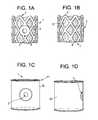
- FIGS. 1 a - ddiscloses side and front views of intervertebral fusion cages of the present invention.
- FIG. 2 adiscloses a side view of an assembly of the present invention, with the cage thereof implanted in a disc space.
- FIG. 2 bdiscloses use of the assembly.
- FIG. 3 adiscloses an exploded assembly of the present invention.
- FIG. 3 bdiscloses a side view of another exploded assembly of the present invention, with the cage thereof implanted in a disc space.
- FIG. 3 cdiscloses a perspective view of an aspiration cage of the present invention.
- FIG. 3 ddiscloses a side view of an aspiration cage of the present invention wrapped in a graft containment bag (or sheath).
- FIG. 4discloses a tube-like load bearing device of the present invention implanted in a long bone.
- FIGS. 5 a - fdisclose a method of the present invention being carried out in a long bone defect.
- FIG. 6discloses a method of the present invention being carried out on an iliac crest.
- FIG. 7discloses steps for implanting a long bone plug of the present invention in a contained bony defect.
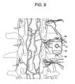
- FIG. 8discloses an aspirating graft jacket implanted between adjacent transverse processes.
- FIG. 9discloses an aspirating graft jacket having nanotubes.
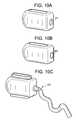
- FIGS. 10 a - ddisclose cages of the present invention with various ports.
- FIGS. 10 e - fdisclose side and front views of a duckbill-type enclosed valve.
- FIG. 11discloses an aspirating cage of the present invention having an endplate seal.
- FIG. 12discloses an aspirating cage of the present invention in which the endplate seal has teeth extending therefrom.
- FIG. 13shows an aspirating cage of the present invention filled with a porous matrix.
- FIGS. 14 a - cshow an aspirating cage of the present invention having two ports.
- FIG. 15discloses the cage of the present invention attached to an insertion device.
- aspirating devices and methodsthat improve stem cell filtering, enhance mixing, increase bony regeneration, and reduce the risk of infection.
- These devices and methodsinclude both implants and instruments that facilitate the in-situ aspiration and mixing of native autograft. The use of such devices and methods subsequently result in bone regeneration without the added operative procedure, manual variability and infection risk associated with the conventional harvesting and external mixing of stem cells.
- the aspiration portmay be selected from the group consisting of a simple hole, a threaded hole, a pierceable membrane such as a septum, a cannulated projection extending out of the implant, and a recess extending into the implant.
- the implantincludes more than one such aspiration port.
- the portmay incorporate a one-way valve to enable aspiration while preventing subsequent leakage.
- the portmay also have a bi-directional valve that enables both a) the aspiration of aspirate into the implant (by drawing a vacuum through the port), and b) the injection of biologics (such as cells, BMPs, drugs, anesthetics, analgesics, or antibiotics) directly into the porous matrix of the implant to enhance bone growth (by injecting through the port).
- biologicssuch as cells, BMPs, drugs, anesthetics, analgesics, or antibiotics
- the portsmay further include modular attachment means for intra-operative insertion, aspiration and/or injection.
- the portmay be designed to have a control feature that controls process variables such as flow rate, pressure and/or delivery of the aspirate through the porous bone substitute matrixes.
- the implantsmay be in the form of a bag, tube or cage. They may be pre-operatively or intra-operatively filled with bone-inducing porous matrixes.
- openings in the bone-contacting surfaces (or endplates) of the cageenable marrow aspiration therethrough following aggravation of the natural endplates to initiate vascular/marrow flow.
- a cage having teeth on its endplatescan be manipulated in-situ to decorticate the bone and thereby enhance vascular flow and aspirate filtering.
- the spinal-fusion cagecan have limited lateral/posterior holes to control vacuum pressure and maximize vascular flow.
- the endplates of the cagemay include peripheral sealing as a means to enhance flow, fit, or conformation or provide for added vacuum capabilities with adjacent endplates.
- the cagecan be fabricated with or placed within a bag (made of, for example, collagen or resorbable polymer) to contain vascularity and stem cells during and after aspiration.
- FIGS. 1 a - dthere are provided front and side views of intervertebral fusion cages of the present invention.
- FIGS. 1 a - bdisclose a standard mesh-type cage 1 fitted with an aspiration port 3 .
- the cagehas been filled with a porous matrix 5 (in this case, a bony regeneration matrix) to assist in the retention of the stem cells in the cage.
- the upper 7 and lower 9 surfaces of the cagehave been beveled to increase endplate vascularity.
- FIGS. 1 c - ddisclose front and side views of the cages of FIGS. 1 a - b , but with a sheath 13 wrapped around the cylindrical portion of the cage. These sheaths helped retain the suction produced by the aspiration.
- FIG. 2 athere is disclosed a side view of an assembly of the present invention, with the cage 15 thereof implanted in a disc space.
- the plunger 17 of the aspiration syringe 19is slowly withdrawn, thereby reducing the pressure in the air-tight cage.
- the low pressure in the cagecauses bone marrow to move from the adjacent vertebral bodies into the cage (as shown by the plurality of arrows).
- the porous matrix provided in the cageretains the stems cells present in the marrow.
- the marrow collected in the syringeis re-injected through the cage in order to retain even more stem cells on the porous matrix.
- FIG. 2 bdiscloses use of the assembly.
- FIG. 3 adiscloses an exploded assembly of the present invention in which the port 21 of the cage 23 is aligned with the needle 25 of an aspirating syringe 27 .
- FIG. 3 bthere is a side view of another exploded assembly of the present invention, with the cage 23 thereof implanted in a disc space.
- the distal end 29 of an aspiration line 31is connected to the port 21 of the cage 23 , while the proximal end 33 of the line is fitted with a valve 35 .
- the purpose of the valveis to allow for disconnection without leakage. During aspiration, the valve will hold the negative pressure. During dispensing, the valve insures the dispensing pressure and prevents leakage.
- the valvecan also control excess vacuum pressure for a predetermined time.
- FIG. 3 cdiscloses a perspective view of an aspiration cage 39 of the present invention. This cage has a port 21 to which an aspiration line 31 is connected. The cage is also filled with porous matrix 41 for retaining the stem cells thereon.
- FIG. 3 ddiscloses a side view of an aspiration cage 43 of the present invention wrapped in a graft containment bag 45 (or sheath).
- the aspirating and filtering devices of the present inventioncan also be used to create long bone graft spacers with enhanced viability and reduced surgical risk.
- These tubular spacersmay be fabricated from polymers, ceramics, or bone substitutes. They can be preoperatively or intra-operatively filled with porous bone substitute matrixes.
- Aspiration port(s) on the long bone spacerenable marrow aspiration and stem cell filtering to enhance viability of the device.
- a method of treating a long bone defect 51 having opposing cancellous surfaces 53comprising the step of:
- an implant of the present inventionis used to improve the healing of a contained defect.
- the defectis first is filled with bone substitutes or matrixes and covered with an osteoconductive porous sheet or matrix.
- In-situ bone marrow(containing stem cells) is then aspirated though the porous sheet and the stem cells are seeded onto the matrix and sheet. This procedure may be accomplished with or without an aspiration port via a flexible and conforming funnel aspirator.
- the funnelcan be deployed minimally invasively to both deliver and implant the porous sheet onto the defect.
- FIG. 5 athe procedure begins with creating an approach to the bony defect BD.
- the defect BDis debrided.
- FIG. 5 cthe debrided area is filled with a porous matrix 63 (for example, a bone substitute or an expandable gel).
- a porous cover sheet 65is applied over the porous matrix housed in the debrided area. The cover sheet is then attached with either fasteners or an adhesive (neither shown).
- a flexible aspiration funnel 67is then laid upon the porous cover sheet.
- an aspirator 69is fluidly connected to the funnel, and a vacuum is drawn through the cover sheet to aspirate marrow into the porous matrix.
- the vacuum pressure associated with the aspirationis monitored and cut off when a desired pressure is obtained, or when the cover sheet or matrix becomes occluded with marrow.
- a method of treating a contained bony defectcomprising the steps of:
- this flexible aspiration method described in FIGS. 5 a - 5 fcan also be utilized for other bony defects, including the iliac crest.
- a method of the present inventionbeing carried out on an iliac crest, wherein the flexible funnel 67 and aspirator 69 draw bone marrow out of the pelvic region and into the porous matrix contained within the iliac crest so that the stem cells in the marrow are retained on the porous matrix.
- FIGS. 7 a - fcontained defects can be filled with aspirating bone plugs 71 that include ports or covers to facilitate marrow aspiration and stem cell filtering.
- FIG. 7 adiscloses such a preferred device of the present invention.
- FIG. 7 athe procedure begins with creating an approach to the bony defect BD.
- the defect BDis debrided.
- FIG. 7 cthe debrided area is filled with a fusion device 71 consisting essentially of inorganic bone or bone substitute.
- FIG. 7 dshows a side view of the fusion device of FIG. 7 c .
- This allograft deviceis cylindrical in structure and made from a portion of a human femoral, tibial or ulnar long bone.
- On one end of the devicethere is an aspiration port 73 adapted for connection to an aspirator.
- the deviceOn the peripheral surface 75 of the device, there are a plurality of securement features 77 (such as teeth).
- the deviceis fabricated from bone substitute and made so that its pores facilitate growth in the longitudinal/axial direction.
- an aspiratorsuch as a syringe 79
- aspirationis applied to draw marrow out of the adjacent bone and into the porous bone plug, wherein the stem cells are retained.
- a method of treating a contained bony defectcomprising the steps of:
- the bone substitutescan be in the form of prefabricated semi-porous bags that are placed within bony structures to enable aspiration of stem cell from adjacent bony structures.
- the “graft jacket”may be utilized for lateral graft in spinal procedures. This device is placed in a generally axial direction to provide intimate contact against opposing transverse processes, which can be intraoperatively burred to enhance vascularity.
- the graft jacket 81comprising:
- the surgeonIn use, the surgeon first aggravates the opposing faces of adjacent transverse processes in order to induce blood flow. Next, the surgeon places the aspirating graft jacket between the transverse processes, with the throughholes contacting the aggravated faces of the transverse processes. Next, the surgeon places an aspirator in fluid connection with the aspiration port of the graft jacket. Lastly, the surgeon applies a vacuum to the aspirator to draw marrow from the transverse processes and into the graft jacket.
- the graft jacket of the present inventionmay contain nanotubes 99 extending longitudinally between the opposing open endfaces of the cage having ports 100 .
- the axial nature of the nanotubesaugments the load-bearing abilities of the graft jacket and further aids the capillary wicking of vascular flow to further enhance directional bone formation.
- Nanotubescan be produced from either carbon, metallics (titanium), polymers (such as PEEK, CFRP, or PET), or ceramics. Nanotubes can be produced from bone substitutes including CaP, HA, or TCP.
- FIGS. 10 a - fthere are provided other embodiments of an intervertebral cage having a port.
- the portmay be in the form of an opening 101 (as in FIG. 10 a ), a septum 103 (as in FIG. 10 b ), an enclosed valve 105 (as in FIG. 10 d ), or an in-line valve 107 (as in FIG. 10 c ).
- an enclosed valveit is preferably in the form of a duckbill-type valve, as shown in FIGS. 10 e and 10 f .
- the portmay be advantageously used for a) in-situ aspiration of autologous material (such as adjacent blood, marrow and stem cells); b) dispensing of bioreactive materials (such as graft, INJECTOS, bone marrow aspirate, and growth factors such as BMPs); and c) re-dispensing of materials post operatively (such as in the event of a failed fusion).
- autologous materialsuch as adjacent blood, marrow and stem cells
- bioreactive materialssuch as graft, INJECTOS, bone marrow aspirate, and growth factors such as BMPs
- re-dispensing of materials post operativelysuch as in the event of a failed fusion
- FIG. 11there is provided another embodiment of the present invention describing a cage 109 with a port 110 and a compressible endplate seal 11 .
- the compressible endplate sealtypically lines an opening in the top or bottom of the cage and is made of elastomers (such as urethane, TPE, thermoplastic polymers and silicones), hydrogels, flexible resorbable polymers, or collagen.
- the compressible endplate sealprovides a number of advantageous functions, including enhancing endplate contact, enhancing vacuum of adjacent marrow, containing aspirate, and containing dispensate.
- an intervertebral fusion cagecomprising:
- FIG. 12there is provided another embodiment of the present invention, describing a cage with a port, an endplate seal and a plurality of teeth 113 extending from the seal.
- the teethmay be used for gripping the opposing endplates and to initiate bleeding bone and marrow flow.
- the teeth that extend from the cage of the present inventionare cannulated. These cannulated teeth can be deployed into the endplates once the cage is placed into the interbody space.
- the inserterhas a feature that triggers the spikes to deploy after insertion. Thus once the syringe is attached it would draw in marrow from the endplates through the holes in these cannulated teeth.
- FIG. 13there is provided another embodiment of the present invention describing a cage with a port, an endplate seal with teeth, and a prefilled graft 115 within the cage.
- the graftacts as a filter to desirably increase stem cell selection/retention.
- the grafthas a pore size of between about 10 and about 20 ⁇ m and is treated with one or more of the following.
- FIG. 14there is provided another embodiment of the present invention describing a cage having two ports 121 , 123 .
- the pair of portscan be used to provide for dual aspiration.
- One of the portscan be a dedicated dispensing port for dispensing materials such as bone marrow aspirate, PRP, growth factors such as BMP.
- the dual portscan be used with a baffle 125 to set up circulation in the cage (with one port allowing inflow and the other allowing only outflow, as in FIG. 14 c ).
- the circulationprovides for enhanced filtering.
- recirculationis provided.
- the cage 130may be inserted into the disc space with an inserter 132 substantially similar to that disclosed in U.S. Pat. Nos. 6,478,800 and 6,755,841 (the specifications of which are hereby incorporated by reference in their entireties), but with a syringe 131 and needle 133 replacing the medial shaft that connects with the implant.
- sufficient bone marrowis drawn into the cage to substantially fill the cage with bone marrow.
- stem cellsselectively adhere to the surfaces of many porous media. Therefore, in other embodiments, an excess of bone marrow is drawn from the vertebral bodies and through the cage in order to concentrate the stem cells in the porous media of the cage.
- the porous mediais made from a biocompatible, implantable graft material.
- the materialhas a charged surface.
- biocompatible, implantable graft materials having a charged surfaceinclude synthetic ceramics comprising calcium phosphate, some polymers, demineralized bone matrix, or mineralized bone matrix.
- cell adhesion moleculesare bound to the surface of the porous media.
- the term “cell adhesion molecules”includes but is not limited to laminins, fibronectin, vitronectin, vascular cell adhesion molecules (V-CAM), intercellular adhesion molecules (1-CAM) and collagen.
- the cell adhesion moleculepreferentially binds stem cells. In other embodiments, the cell adhesion molecule has a low affinity for partially or fully differentiated blood cells.
- the cage of the present inventionincludes a drug delivery reservoir. These reservoirs serve the same function as drug delivery microspheres but provide a more structured approach.
- the cageis designed (and the flow rate is selected) so that the flow of marrow therethrough fills the porous matrix in a reasonable time period, but does not flow so fast that shear stresses cause the stem cells to lyse.
- the load-bearing fusion device of the present inventionmay be constructed of metals (such as Ti, Ti64, CoCr, and stainless steel), polymers (such as PEEK, polyethylene, polypropylene, and PET), resorbable polymers (such as PLA, PDA, PEO, PEG, PVA, and capralactides), and allograft, bone substitutes (such as TCP, HA, and CaP)
- metalssuch as Ti, Ti64, CoCr, and stainless steel
- polymerssuch as PEEK, polyethylene, polypropylene, and PET
- resorbable polymerssuch as PLA, PDA, PEO, PEG, PVA, and capralactides
- allograft, bone substitutessuch as TCP, HA, and CaP
- the fusion device housing of the present inventioncan be made of any structural biocompatible material including resorbable (PLA, PLGA, etc.), non-resorbable polymers (CFRP, PEEK, UHMWPE, PDS), metallics (SS, Ti-6Al-4V, CoCr, etc.), as well as materials that are designed to encourage bony regeneration (allograft, bone substitute-loaded polymers, growth factor-loaded polymers, ceramics, etc.).
- the materials for the fusion device housingare biocompatible and generally similar to those disclosed in the prior art. Examples of such materials are metal, PEEK and ceramic.
- the fusion device housingis manufactured from a material that possesses the desirable strength and stiffness characteristics for use as a fusion cage component.
- These components of the present inventionmay be made from any non-resorbable material appropriate for human surgical implantation, including but not limited to, surgically appropriate metals, and non-metallic materials, such as carbon fiber composites, polymers and ceramics.
- the cage materialis selected from the group consisting of PEEK, ceramic and metallic.
- the cage materialis preferably selected from the group consisting of metal and composite (such as PEEK/carbon fiber).
- the metalis preferably selected from the group consisting of titanium, titanium alloys (such as Ti-6Al-4V), chrome alloys (such as CrCo or Cr—Co—Mo) and stainless steel.
- the polymeris preferably selected from the group consisting of polyesters, (particularly aromatic esters such as polyalkylene terephthalates, polyamides; polyalkenes; poly(vinyl fluoride); PTFE; polyarylethyl ketone PAEK; polyphenylene and mixtures thereof.
- the ceramicis preferably selected from the group consisting of alumina, zirconia and mixtures thereof. It is preferred to select an alumina-zirconia ceramic, such as BIOLOX DeltaTM, available from CeramTec of Plochingen, Germany.
- the cage membercomprises PEEK. In others, it is a ceramic.
- the fusion device housingconsists essentially of a metallic material, preferably a titanium alloy or a chrome-cobalt alloy.
- the fusion device housing componentsare made of a stainless steel alloy, preferably BioDur® CCM Plus® Alloy available from Carpenter Specialty Alloys, Carpenter Technology Corporation of Wyomissing, Pa.
- the fusion device housing componentsare coated with a sintered beadcoating, preferably PorocoatTM, available from DePuy Orthopaedics of Warsaw, Ind.
- the fusion device housingis made from a composite comprising carbon fiber.
- Composites comprising carbon fiberare advantageous in that they typically have a strength and stiffness that is superior to neat polymer materials such as a polyarylethyl ketone PAEK.
- the fusion device housingis made from a polymer composite such as a PEKK-carbon fiber composite.
- the composite comprising carbon fiberfurther comprises a polymer.
- the polymeris a polyarylethyl ketone (PAEK). More preferably, the PAEK is selected from the group consisting of polyetherether ketone (PEEK), polyether ketone ketone (PEKK) and polyether ketone (PEK). In preferred embodiments, the PAEK is PEEK.
- the carbon fibercomprises between 1 vol % and 60 vol % (more preferably, between 10 vol % and 50 vol %) of the composite.
- the polymer and carbon fibersare homogeneously mixed.
- the materialis a laminate.
- the carbon fiberis present in a chopped state.
- the chopped carbon fibershave a median length of between 1 mm and 12 mm, more preferably between 4.5 mm and 7.5 mm.
- the carbon fiberis present as continuous strands.
- the compositecomprises:
- PAEKpolyarylethyl ketone
- polyarylethyl ketoneis selected from the group consisting of polyetherether ketone (PEEK), polyether ketone ketone (PEKK) and polyether ketone (PEK).
- the compositeconsists essentially of PAEK and carbon fiber. More preferably, the composite comprises 60-80 wt % PAEK and 20-40 wt % carbon fiber. Still more preferably the composite comprises 65-75 wt % PAEK and 25-35 wt % carbon fiber.
- the housingis typically filled with at least one bone forming agent (BFA).
- BFAbone forming agent
- the bone-forming agentmay be:
- the housingcontains a liquid carrier, and the bone forming agent is soluble in the carrier.
- the bone forming agentis a growth factor.
- growth factorencompasses any cellular product that modulates the growth or differentiation of other cells, particularly connective tissue progenitor cells.
- the growth factors that may be used in accordance with the present inventioninclude, but are not limited to, members of the fibroblast growth factor family, including acidic and basic fibroblast growth factor (FGF-1 and FGF-2) and FGF-4; members of the platelet-derived growth factor (PDGF) family, including PDGF-AB, PDGF-BB and PDGF-AA; EGFs; VEGF; members of the insulin-like growth factor (IGF) family, including IGF-I and -II; the TGF- ⁇ superfamily, including TGF- ⁇ 1, 2 and 3; osteoid-inducing factor (OIF), angiogenin(s); endothelins; hepatocyte growth factor and keratinocyte growth factor; members of the bone morphogenetic proteins (BMPs) BMP-1,
- BMPsbone morphogen
- platelet concentrateis provided as the bone forming agent.
- the growth factors released by the plateletsare present in an amount at least two-fold (e.g., four-fold) greater than the amount found in the blood from which the platelets were taken.
- the platelet concentrateis autologous.
- the platelet concentrateis platelet rich plasma (PRP). PRP is advantageous because it contains growth factors that can restimulate the growth of the bone, and because its fibrin matrix provides a suitable scaffold for new tissue growth.
- the bone forming agentcomprises an effective amount of a bone morphogenic protein (BMP).
- BMPsbeneficially increasing bone formation by promoting the differentiation of mesenchymal stem cells (MSCs) into osteoblasts and their proliferation.
- between about 1 ng and about 10 mg of BMPare administered into the target disc space. In some embodiments, between about 1 microgram ( ⁇ g) and about 1 mg of BMP are administered into the target disc space.
- the bone forming agentis a porous matrix, and is preferably injectable.
- the porous matrix of the present inventionmay contain porous or semi-porous collagen, extracellular matrices, metals (such as Ti, Ti64, CoCr, and stainless steel), polymers (such as PEEK, polyethylene, polypropylene, and PET) resorbable polymers (such as PLA, PDA, PEO, PEG, PVA, and capralactides), bone substitutes (such as TCP, HA, and CaP), autograft, allograft, xenograft, and/or blends thereof.
- Matricesmay be orientated to enable flow from bony attachment locations to the aspiration port. Matrices may be layered with varying densities, pore structures, materials to enable increase stem filter at desired locations via density, pore size, affinity, as well as fluid flow control (laminar, turbilant, and/or tortuous path).
- the porous matrixis a mineral.
- this mineralcomprises calcium and phosphorus.
- the mineralis selected from the group consisting of calcium phosphate, tricalcium phosphate and hydroxyapatite.
- the average porosity of the matrixis between about 20 and about 500 ⁇ m, for example, between about 50 and about 250 ⁇ m.
- in situ porosityis produced in the injected matrix to produce a porous scaffold in the interbody space. Once the in situ porosity is produced in the space, the surgeon can inject other therapeutic compounds into the porosity, thereby treating the surrounding tissues and enhancing the remodeling process of the target tissue.
- the mineralis administered in a granule form. It is believed that the administration of granular minerals promotes the formation of the bone growth around the minerals such that osteointegration occurs.
- the mineralis administered in a settable-paste form.
- the pastesets up in vivo, and thereby immediately imparts post-treatment mechanical support to the interbody space.
- the treatmentis delivered via injectable absorbable or non-absorbable cement to the target space.
- the treatmentis formulated using bioabsorbable macro-sphere technologies, such that it will allow the release of the bone forming agent.
- the cementwill provide the initial stability required to treat pain in target tissues. These tissues include, but are not limited to, hips, knee, vertebral body and iliac crest.
- the cementis selected from the group consisting of calcium phosphate, tricalcium phosphate and hydroxyapatite.
- the cementis any hard biocompatible cement, including PMMA, processed autogenous and allograft bone. Hydroxylapatite is a preferred cement because of its strength and biological profile. Tricalcium phosphate may also be used alone or in combination with hydroxylapatite, particularly if some degree of resorption is desired in the cement.
- the porous matrixcomprises a resorbable polymeric material.
- the bone forming agentcomprises an injectable precursor fluid that produces the in situ formation of a mineralized collagen composite.
- the injectable precursor fluidcomprises:
- the liposomesare loaded with dipalmitoylphosphatidylcholine (90 mol %) and dimyristoyl phosphatidylcholine (10 mol %). These liposomes are stable at room temperature but form calcium phosphate mineral when heated above 35° C., a consequence of the release of entrapped salts at the lipid chain melting transition.
- dipalmitoylphosphatidylcholine90 mol %)
- dimyristoyl phosphatidylcholine10 mol %.
- the in situ mineralization of collagencould be achieved by an increase in temperature achieved by other types of reactions including, but not limited to, chemical, enzymatic, magnetic, electric, photo- or nuclear. Suitable sources thereof include light, chemical reaction, enzymatically controlled reaction and an electric wire embedded in the material.
- a wirecan first be embedded in the space, heated to create the calcium deposition, and then withdrawn.
- this wiremay be a shape memory such as nitinol that can form the shape.
- an electrically-conducting polymercan be selected as the temperature raising element. This polymer is heated to form the collagen, and is then subject to disintegration and resorption in situ, thereby providing space adjacent the mineralized collagen for the bone to form.
- the osteoconductive materialcomprises calcium and phosphorus. In some embodiments, the osteoconductive material comprises hydroxyapatite. In some embodiments, the osteoconductive material comprises collagen. In some embodiments, the osteoconductive material is in a particulate form.
- Nanotubes or nanocrystalscan be orientated in a generally axial direction to provide for load bearing abilities as well as capillary wicking of vascular flow to further enhance directional bone formation.
- Biocompatible nanotubescan currently be produced from either carbon or titanium or bone substitutes including Ca, HA, and TCP.
- the bone forming agentis a plurality of viable ex vivo osteoprogenitor cells.
- viable cellsintroduced into the interbody space, have the capability of at least partially supplementing the in situ drawn stem cells in the generation of new bone for the interbody space.
- these cellsare obtained from another human individual (allograft), while in other embodiments, the cells are obtained from the same individual (autograft).
- the cellsare taken from bone tissue, while in others, the cells are taken from a non-bone tissue (and may, for example, be mesenchymal stem cells, chondrocytes or fibroblasts).
- autograft osteocytessuch as from the knee, hip, shoulder, finger or ear may be used.
- the viable cellswhen viable ex vivo cells are selected as an additional therapeutic agent or substance, the viable cells comprise mesenchymal stem cells (MSCs).
- MSCsprovide a special advantage for administration into the interbody space because it is believed that they can more readily survive the relatively harsh environment present in the space; that they have a desirable level of plasticity; and that they have the ability to proliferate and differentiate into the desired cells.
- the mesenchymal stem cellsare obtained from bone marrow, such as autologous bone marrow.
- the mesenchymal stem cellsare obtained from adipose tissue, preferably autologous adipose tissue.
- the mesenchymal stem cells injected into the interbody spaceare provided in an unconcentrated form, e.g., from fresh bone marrow. In others, they are provided in a concentrated form. When provided in concentrated form, they can be uncultured. Uncultured, concentrated MSCs can be readily obtained by centrifugation, filtration, or immuno-absorption. When filtration is selected, the methods disclosed in U.S. Pat. No. 6,049,026 (“Muschler”), the specification of which is incorporated herein by reference in its entirety, can be used. In some embodiments, the matrix used to filter and concentrate the MSCs is also administered into the interbody space.
- bone cellswhich may be from either an allogeneic or an autologous source
- mesenchymal stem cellsmay be genetically modified to produce an osteoinductive bone anabolic agent which could be chosen from the list of growth factors named herein. The production of these osteopromotive agents may lead to bone growth.
- the plasmidcontains the genetic code for human TGF- ⁇ or erythropoietin (EPO).
- the additional therapeutic agentis selected from the group consisting of viable cells and plasmid DNA.
- a matrixmay be made from hydrogels or may incorporate a hydrogel as component of the final structure.
- a hydrogelmay be used to expand and enhance filling, improve handling characteristics or increase vacuum pressure. The increased vacuum pressure may be used to determine adequate hydration/stem cell filtration.
- excess bone marrow aspiratecan be collected and mixed with added graft extenders including collagen like the HEALOSTM, INJECTOSTM and HEALOS FXTM, each of which is available from DePuy Spine Inc, Raynham, Mass., USA.
- graft extendersincluding collagen like the HEALOSTM, INJECTOSTM and HEALOS FXTM, each of which is available from DePuy Spine Inc, Raynham, Mass., USA.
Landscapes
- Health & Medical Sciences (AREA)
- Engineering & Computer Science (AREA)
- Biomedical Technology (AREA)
- Orthopedic Medicine & Surgery (AREA)
- Transplantation (AREA)
- Life Sciences & Earth Sciences (AREA)
- Animal Behavior & Ethology (AREA)
- Veterinary Medicine (AREA)
- Public Health (AREA)
- Heart & Thoracic Surgery (AREA)
- General Health & Medical Sciences (AREA)
- Cardiology (AREA)
- Vascular Medicine (AREA)
- Oral & Maxillofacial Surgery (AREA)
- Neurology (AREA)
- Surgery (AREA)
- Physical Education & Sports Medicine (AREA)
- Nuclear Medicine, Radiotherapy & Molecular Imaging (AREA)
- Medical Informatics (AREA)
- Molecular Biology (AREA)
- Chemical & Material Sciences (AREA)
- Dispersion Chemistry (AREA)
- Prostheses (AREA)
Abstract
Description
- fusion device aspiration ports,
- fusion device covers or sheaths that improve the suction through the cage;
- porous sheets that allow suction therethrough but retain cells,
- graft matrixes designed for controlled stem cell filtering, collection and bony regeneration, and
- insertion and aspiration instruments including a flexible aspiration funnel.
- a) an intervertebral fusion cage, comprising:
- i) an upper surface adapted for gripping an upper vertebral body and comprising an upper throughole therethrough,
- ii) a lower surface adapted for gripping a lower vertebral body and comprising a lower throughole therethrough,
- iii) a sidewall connecting the upper and lower surfaces and comprising an aspiration port therethrough, and
- b) an aspirator,
wherein the aspirator connects to the aspiration port to provide fluid connection between the fusion cage and the aspirator.
- a) an intervertebral fusion cage, comprising:
- a) inserting a
fusion cage 55 into the defect, the cage having anaspiration port 57 and opposingporous endplates 59, - b) orienting the cage so that each porous endplate of the cage abuts one of the cancellous surfaces,
- c) fluidly connecting an
aspirator 61 to the port, and - d) actuating the aspirator to lower pressure in the cage, thereby drawing bone marrow from the cancellous surfaces into the cage.
- a) inserting a
- a) debriding the bony defect,
- b) filling the defect with a porous matrix,
- c) placing a porous sheet over the porous matrix,
- d) placing a flexible funnel on the porous sheet, the funnel being fluidly connected to an aspirator, and
- e) actuating the aspirator to draw bone marrow from the defect into the porous matrix and cover sheet.
- a) debriding the bony defect,
- b) filling the defect with a porous allograft plug,
- c) fluidly connecting the plug to an aspirator, and
- d) actuating the aspirator to draw bone marrow from the defect into the porous allograft plug.
- a) an
expandable bag 83 having upper and lower throughholes85 and anaspiration port 87, and - b) a porous matrix (not shown) contained within the bag.
- a) an
- a) decorticating opposing faces of the adjacent transverse processes,
- b) placing a graft jacket having an aspiration port between the opposing faces so that upper and lower throughholes of the graft jacket contact the opposing faces,
- c) fluidly connecting the port to an aspirator, and
- d) actuating the aspirator to draw bone marrow from the transverse processes into the cage.
- a) an upper surface adapted for gripping an upper vertebral body and comprising an upper throughole therethrough,
- b) a lower surface adapted for gripping a lower vertebral body and comprising a lower throughole therethrough,
- c) a sidewall connecting the upper and lower surfaces and comprising an aspiration port therethrough, and
at least one compressible endplate seal disposed about either the upper or lower throughhole.
- a.
Type 1 or 2 collagen, - b. fibrinogen, fibronectin, and/or thrombin, or
- c. gelatin.
In some embodiments, a sheath (not shown) may be disposed around the cage ofFIG. 13 . The sheath may be used to advantageously enhance vacuum of adjacent marrow, contain aspirate, and contain dispensate.
- a.
- a) a growth factor (such as an osteoinductive or angiogenic factor),
- b) osteoconductive (such as a porous matrix of granules),
- c) osteogenic (such as viable osteoprogenitor cells), or
- d) plasmid DNA.
- a) a first formulation comprising an acid-soluble type I collagen solution (preferably between about 1 mg/ml and about 7 mg/ml collagen) and
- b) a second formulation comprising liposomes containing calcium and phosphate.
Claims (22)
Priority Applications (4)
| Application Number | Priority Date | Filing Date | Title |
|---|---|---|---|
| US12/634,647US9168138B2 (en) | 2009-12-09 | 2009-12-09 | Aspirating implants and method of bony regeneration |
| US14/877,901US20160081804A1 (en) | 2009-12-09 | 2015-10-07 | Aspirating Implants and Method of Bony Regeneration |
| US15/218,210US9801725B2 (en) | 2009-12-09 | 2016-07-25 | Aspirating implants and method of bony regeneration |
| US15/721,090US10342662B2 (en) | 2009-12-09 | 2017-09-29 | Aspirating implants and method of bony regeneration |
Applications Claiming Priority (1)
| Application Number | Priority Date | Filing Date | Title |
|---|---|---|---|
| US12/634,647US9168138B2 (en) | 2009-12-09 | 2009-12-09 | Aspirating implants and method of bony regeneration |
Related Child Applications (1)
| Application Number | Title | Priority Date | Filing Date |
|---|---|---|---|
| US14/877,901ContinuationUS20160081804A1 (en) | 2009-12-09 | 2015-10-07 | Aspirating Implants and Method of Bony Regeneration |
Publications (2)
| Publication Number | Publication Date |
|---|---|
| US20110137418A1 US20110137418A1 (en) | 2011-06-09 |
| US9168138B2true US9168138B2 (en) | 2015-10-27 |
Family
ID=44082775
Family Applications (4)
| Application Number | Title | Priority Date | Filing Date |
|---|---|---|---|
| US12/634,647Active2032-03-12US9168138B2 (en) | 2009-12-09 | 2009-12-09 | Aspirating implants and method of bony regeneration |
| US14/877,901AbandonedUS20160081804A1 (en) | 2009-12-09 | 2015-10-07 | Aspirating Implants and Method of Bony Regeneration |
| US15/218,210ActiveUS9801725B2 (en) | 2009-12-09 | 2016-07-25 | Aspirating implants and method of bony regeneration |
| US15/721,090ActiveUS10342662B2 (en) | 2009-12-09 | 2017-09-29 | Aspirating implants and method of bony regeneration |
Family Applications After (3)
| Application Number | Title | Priority Date | Filing Date |
|---|---|---|---|
| US14/877,901AbandonedUS20160081804A1 (en) | 2009-12-09 | 2015-10-07 | Aspirating Implants and Method of Bony Regeneration |
| US15/218,210ActiveUS9801725B2 (en) | 2009-12-09 | 2016-07-25 | Aspirating implants and method of bony regeneration |
| US15/721,090ActiveUS10342662B2 (en) | 2009-12-09 | 2017-09-29 | Aspirating implants and method of bony regeneration |
Country Status (1)
| Country | Link |
|---|---|
| US (4) | US9168138B2 (en) |
Cited By (5)
| Publication number | Priority date | Publication date | Assignee | Title |
|---|---|---|---|---|
| US20170000624A1 (en)* | 2015-06-30 | 2017-01-05 | Mark Schallenberger | Expandable bone grafts and methods of manufacture thereof |
| US9801725B2 (en) | 2009-12-09 | 2017-10-31 | DePuy Synthes Products, Inc. | Aspirating implants and method of bony regeneration |
| US10617530B2 (en) | 2011-07-14 | 2020-04-14 | Seaspine, Inc. | Laterally deflectable implant |
| US10932918B2 (en) | 2014-03-04 | 2021-03-02 | DePuy Synthes Products, Inc. | Post-operative bone growth stimulant introduction method |
| US11446882B2 (en) | 2014-03-05 | 2022-09-20 | Bacterin International, Inc. | Shaped bone fiber-based products and a method of manufacture thereof |
Families Citing this family (17)
| Publication number | Priority date | Publication date | Assignee | Title |
|---|---|---|---|---|
| US7744635B2 (en)* | 2004-06-09 | 2010-06-29 | Spinal Generations, Llc | Spinal fixation system |
| KR20110033199A (en)* | 2008-06-19 | 2011-03-30 | 신세스 게엠바하 | Bone Screw Percussion Augmented Implants, Systems and Technologies |
| US9700431B2 (en)* | 2008-08-13 | 2017-07-11 | Smed-Ta/Td, Llc | Orthopaedic implant with porous structural member |
| US10842645B2 (en) | 2008-08-13 | 2020-11-24 | Smed-Ta/Td, Llc | Orthopaedic implant with porous structural member |
| US9427319B2 (en)* | 2012-08-27 | 2016-08-30 | Robert R. Gray | Vascularized porous metal orthopaedic implant devices |
| US20140114382A1 (en)* | 2012-09-10 | 2014-04-24 | Keun-Young Anthony Kim | Stimulating bone growth and controlling spinal cord pain |
| RU2017125255A (en)* | 2014-12-16 | 2019-01-18 | Керамтек Гмбх | INTERDERVERSE CAGES AND INSTALLATION INSTRUMENTS |
| US20160166284A1 (en)* | 2014-12-16 | 2016-06-16 | Oxford Performance Materials, Inc. | Methods and Systems For Local Administration of Therapeutics |
| US20160331539A1 (en)* | 2015-05-12 | 2016-11-17 | Elwha Llc | Modifiable implants |
| US9877837B2 (en)* | 2015-09-15 | 2018-01-30 | Arthrex, Inc. | Devices for enhancing the fatigue and mechanical properties of bone cement and other biomaterials |
| US10285825B2 (en)* | 2016-04-07 | 2019-05-14 | Howmedica Osteonics Corp. | Surgical insertion instruments |
| WO2018165571A1 (en)* | 2017-03-10 | 2018-09-13 | Life Spine, Inc. (A Delaware Corporation) | 3-d printed orthopedic implants |
| EP3456297B1 (en) | 2017-09-15 | 2023-10-04 | Howmedica Osteonics Corp. | Instruments for expandable interbody implants |
| CA3029952A1 (en)* | 2018-01-24 | 2019-07-24 | Smed-Ta/Td, Llc | Orthopaedic implant with porous structural member |
| RU2695893C1 (en)* | 2018-09-10 | 2019-07-29 | Андрей Викторович Матулевич | Method for surgical treatment of destructive spinal diseases |
| KR102600160B1 (en)* | 2021-08-26 | 2023-11-08 | 주식회사 코렌텍 | Intervertebral Body Fusion Prosthesis With Porous Structure of Shell Type |
| CN120360747B (en)* | 2025-06-25 | 2025-08-29 | 浙江嘉佑医疗器械有限公司 | Anterior cervical interbody fusion cage |
Citations (15)
| Publication number | Priority date | Publication date | Assignee | Title |
|---|---|---|---|---|
| US5824084A (en) | 1996-07-03 | 1998-10-20 | The Cleveland Clinic Foundation | Method of preparing a composite bone graft |
| US6001130A (en)* | 1994-11-14 | 1999-12-14 | Bryan; Vincent | Human spinal disc prosthesis with hinges |
| US20010008980A1 (en)* | 1997-08-13 | 2001-07-19 | Cambridge Scientific, Inc. | Resorbable interbody spinal fusion devices |
| US20020107573A1 (en)* | 1999-03-07 | 2002-08-08 | Discure Ltd. | Method and apparatus for computerized surgery |
| US6478800B1 (en) | 2000-05-08 | 2002-11-12 | Depuy Acromed, Inc. | Medical installation tool |
| US6660038B2 (en)* | 2000-03-22 | 2003-12-09 | Synthes (Usa) | Skeletal reconstruction cages |
| US20040225360A1 (en)* | 2000-12-14 | 2004-11-11 | Malone David G. | Devices and methods for facilitating controlled bone growth or repair |
| US20050065609A1 (en)* | 2001-11-19 | 2005-03-24 | Douglas Wardlaw | Intervertebral disc prosthesis |
| US20050124969A1 (en)* | 2003-03-18 | 2005-06-09 | Fitzgerald Peter J. | Methods and devices for retrieval of a medical agent from a physiological efferent fluid collection site |
| US20050154460A1 (en)* | 2004-01-09 | 2005-07-14 | Yundt Kent D. | Method, system and apparatus for interbody fusion |
| US20060095135A1 (en)* | 2001-10-05 | 2006-05-04 | Nebojsa Kovacevic | Dual-tray prosthesis |
| US20070142916A1 (en)* | 2005-12-21 | 2007-06-21 | Olson Stanley W Jr | Bone graft composition, method and implant |
| US20080154377A1 (en) | 2006-12-22 | 2008-06-26 | Voellmicke John C | Composite vertebral spacers and instrument |
| US20100174243A1 (en)* | 2009-01-05 | 2010-07-08 | Warsaw Orthopedic, Inc. | Apparatus for Delivery of Therapeutic Material to an Intervertebral Disc and Method of Use |
| US20100268343A1 (en)* | 2009-04-16 | 2010-10-21 | Warsaw Orthopedic, Inc. | Vertebral endplate connection implant and method |
Family Cites Families (189)
| Publication number | Priority date | Publication date | Assignee | Title |
|---|---|---|---|---|
| NL45585C (en) | 1936-05-28 | 1900-01-01 | ||
| US2170111A (en) | 1936-05-28 | 1939-08-22 | Rohm & Haas | Manufacture of amines |
| US2229024A (en) | 1939-05-23 | 1941-01-21 | Rohm & Haas | Aromatic ether of polyalkoxyalkylalkylene polyamines and process for obtaining them |
| US2826532A (en) | 1952-04-15 | 1958-03-11 | Gen Aniline & Film Corp | Process of stabilizing polyvinyl pyrrolidone-iodine compositions |
| BE615889A (en) | 1952-04-15 | 1900-01-01 | ||
| US2900305A (en) | 1952-04-15 | 1959-08-18 | Gen Aniline & Film Corp | Preparation of iodine polyvinylpyrrolidone adducts |
| US2710277A (en) | 1952-04-23 | 1955-06-07 | West Laboratories Inc | Iodine phosphate ester compositions |
| US2977315A (en) | 1956-09-12 | 1961-03-28 | Lazarus Lab Inc | Water soluble iodine-phosphoric-acidsynthetic detergent composition |
| US3228828A (en) | 1963-02-15 | 1966-01-11 | Standard Naphthalene Products | Insecticide composition comprising naphthalene and paraffinic hydrocarbon |
| SU557755A3 (en) | 1968-08-19 | 1977-05-05 | Янссен Фармасьютика Н.В. (Фирма) | Method for preparing imidazole derivatives |
| SE391122B (en)* | 1971-01-25 | 1977-02-07 | Cutter Lab | PROTESTS IN THE FORM OF A SPINE BONIC DISC AND PROCEDURES FOR MANUFACTURE THEREOF |
| US4352883A (en) | 1979-03-28 | 1982-10-05 | Damon Corporation | Encapsulation of biological material |
| US4495174A (en) | 1982-06-21 | 1985-01-22 | Research Corporation | Anesthetic polyorganophosphazenes |
| US4440921A (en) | 1982-06-21 | 1984-04-03 | Research Corporation | Coupling of polyorganophosphazenes to carboxylic acid |
| US4651717A (en) | 1985-04-04 | 1987-03-24 | Dow Corning Corporation | Multiple envelope tissue expander device |
| US4645503A (en) | 1985-08-27 | 1987-02-24 | Orthomatrix Inc. | Moldable bone-implant material |
| US4743256A (en) | 1985-10-04 | 1988-05-10 | Brantigan John W | Surgical prosthetic implant facilitating vertebral interbody fusion and method |
| US5133755A (en) | 1986-01-28 | 1992-07-28 | Thm Biomedical, Inc. | Method and apparatus for diodegradable, osteogenic, bone graft substitute device |
| US4880622A (en) | 1986-05-20 | 1989-11-14 | Research Corporation Technologies, Inc. | Water-soluble phosphazene polymers having pharmacological applications |
| GB8620937D0 (en) | 1986-08-29 | 1986-10-08 | Shepperd J A N | Spinal implant |
| CH671691A5 (en) | 1987-01-08 | 1989-09-29 | Sulzer Ag | |
| US4772287A (en) | 1987-08-20 | 1988-09-20 | Cedar Surgical, Inc. | Prosthetic disc and method of implanting |
| US5282856A (en) | 1987-12-22 | 1994-02-01 | Ledergerber Walter J | Implantable prosthetic device |
| CA1333209C (en) | 1988-06-28 | 1994-11-29 | Gary Karlin Michelson | Artificial spinal fusion implants |
| US5059193A (en) | 1989-11-20 | 1991-10-22 | Spine-Tech, Inc. | Expandable spinal implant and surgical method |
| US6203565B1 (en) | 1990-06-28 | 2001-03-20 | Peter M. Bonutti | Surgical devices assembled using heat bondable materials |
| US5410016A (en) | 1990-10-15 | 1995-04-25 | Board Of Regents, The University Of Texas System | Photopolymerizable biodegradable hydrogels as tissue contacting materials and controlled-release carriers |
| US6197325B1 (en) | 1990-11-27 | 2001-03-06 | The American National Red Cross | Supplemented and unsupplemented tissue sealants, methods of their production and use |
| US5123926A (en) | 1991-02-22 | 1992-06-23 | Madhavan Pisharodi | Artificial spinal prosthesis |
| US5390683A (en) | 1991-02-22 | 1995-02-21 | Pisharodi; Madhavan | Spinal implantation methods utilizing a middle expandable implant |
| US5192327A (en) | 1991-03-22 | 1993-03-09 | Brantigan John W | Surgical prosthetic implant for vertebrae |
| NL9200288A (en) | 1992-02-17 | 1993-09-16 | Acromed Bv | DEVICE FOR FIXING AT LEAST A PART OF THE CERVICAL AND / OR THORACAL SPIRIT COLUMN. |
| ES2153378T3 (en) | 1992-02-28 | 2001-03-01 | Univ Texas | PHOTOPOLIMERIZABLE BIODEGRADABLE HYDROGELS AS FABRIC CONTACT MATERIALS AND CONTROLLED DISCHARGE CARRIER. |
| US5985307A (en) | 1993-04-14 | 1999-11-16 | Emory University | Device and method for non-occlusive localized drug delivery |
| US5522895A (en) | 1993-07-23 | 1996-06-04 | Rice University | Biodegradable bone templates |
| US5443514A (en) | 1993-10-01 | 1995-08-22 | Acromed Corporation | Method for using spinal implants |
| US5397364A (en) | 1993-10-12 | 1995-03-14 | Danek Medical, Inc. | Anterior interbody fusion device |
| US5368386A (en)* | 1993-11-16 | 1994-11-29 | Murray; William M. | Manual bone cement mixing device |
| US5888220A (en) | 1994-05-06 | 1999-03-30 | Advanced Bio Surfaces, Inc. | Articulating joint repair |
| US6248131B1 (en) | 1994-05-06 | 2001-06-19 | Advanced Bio Surfaces, Inc. | Articulating joint repair |
| US5571189A (en) | 1994-05-20 | 1996-11-05 | Kuslich; Stephen D. | Expandable fabric implant for stabilizing the spinal motion segment |
| AU2621295A (en) | 1994-05-24 | 1995-12-18 | Smith & Nephew Plc | Intervertebral disc implant |
| US5980522A (en) | 1994-07-22 | 1999-11-09 | Koros; Tibor | Expandable spinal implants |
| US5562736A (en) | 1994-10-17 | 1996-10-08 | Raymedica, Inc. | Method for surgical implantation of a prosthetic spinal disc nucleus |
| AU3795395A (en) | 1994-11-30 | 1996-06-06 | Ethicon Inc. | Hard tissue bone cements and substitutes |
| US5665122A (en) | 1995-01-31 | 1997-09-09 | Kambin; Parviz | Expandable intervertebral cage and surgical method |
| US5860973A (en) | 1995-02-27 | 1999-01-19 | Michelson; Gary Karlin | Translateral spinal implant |
| US6147168A (en) | 1995-03-06 | 2000-11-14 | Ethicon, Inc. | Copolymers of absorbable polyoxaesters |
| US5658335A (en) | 1995-03-09 | 1997-08-19 | Cohort Medical Products Group, Inc. | Spinal fixator |
| US5676976A (en) | 1995-05-19 | 1997-10-14 | Etex Corporation | Synthesis of reactive amorphous calcium phosphates |
| US6027742A (en) | 1995-05-19 | 2000-02-22 | Etex Corporation | Bioresorbable ceramic composites |
| US5833657A (en) | 1995-05-30 | 1998-11-10 | Ethicon, Inc. | Single-walled balloon catheter with non-linear compliance characteristic |
| US5702449A (en) | 1995-06-07 | 1997-12-30 | Danek Medical, Inc. | Reinforced porous spinal implants |
| US6113624A (en) | 1995-10-02 | 2000-09-05 | Ethicon, Inc. | Absorbable elastomeric polymer |
| KR100415064B1 (en) | 1995-10-20 | 2005-04-06 | 신테스 아게 츄어 | Intervertebral implant |
| DE59510855D1 (en) | 1995-11-08 | 2004-03-18 | Ct Pulse Orthopedics Ltd | Intervertebral prosthesis |
| US5807327A (en) | 1995-12-08 | 1998-09-15 | Ethicon, Inc. | Catheter assembly |
| FR2753368B1 (en) | 1996-09-13 | 1999-01-08 | Chauvin Jean Luc | EXPANSIONAL OSTEOSYNTHESIS CAGE |
| US5782832A (en) | 1996-10-01 | 1998-07-21 | Surgical Dynamics, Inc. | Spinal fusion implant and method of insertion thereof |
| EP0873145A2 (en) | 1996-11-15 | 1998-10-28 | Advanced Bio Surfaces, Inc. | Biomaterial system for in situ tissue repair |
| US5836948A (en) | 1997-01-02 | 1998-11-17 | Saint Francis Medical Technologies, Llc | Spine distraction implant and method |
| US6083522A (en) | 1997-01-09 | 2000-07-04 | Neucoll, Inc. | Devices for tissue repair and methods for preparation and use thereof |
| US5866165A (en) | 1997-01-15 | 1999-02-02 | Orquest, Inc. | Collagen-polysaccharide matrix for bone and cartilage repair |
| WO1998034552A1 (en) | 1997-02-06 | 1998-08-13 | Surgical Dynamics | Expandable non-threaded spinal fusion device |
| DE19710392C1 (en) | 1997-03-13 | 1999-07-01 | Haehnel Michael | Slipped disc implant comprises an extensible, hinged or wound body |
| US6071982A (en) | 1997-04-18 | 2000-06-06 | Cambridge Scientific, Inc. | Bioerodible polymeric semi-interpenetrating network alloys for surgical plates and bone cements, and method for making same |
| US5800549A (en) | 1997-04-30 | 1998-09-01 | Howmedica Inc. | Method and apparatus for injecting an elastic spinal implant |
| US6045579A (en) | 1997-05-01 | 2000-04-04 | Spinal Concepts, Inc. | Adjustable height fusion device |
| US6852095B1 (en)* | 1997-07-09 | 2005-02-08 | Charles D. Ray | Interbody device and method for treatment of osteoporotic vertebral collapse |
| CA2328229C (en) | 1997-07-09 | 2007-04-17 | Tegementa, L.L.C. | Interbody device and method for treatment of osteoporotic vertebral collapse |
| US5837752A (en) | 1997-07-17 | 1998-11-17 | Massachusetts Institute Of Technology | Semi-interpenetrating polymer networks |
| US5865848A (en) | 1997-09-12 | 1999-02-02 | Artifex, Ltd. | Dynamic intervertebral spacer and method of use |
| US6652592B1 (en) | 1997-10-27 | 2003-11-25 | Regeneration Technologies, Inc. | Segmentally demineralized bone implant |
| AT405367B (en) | 1998-01-23 | 1999-07-26 | Fuss Franz K Dipl Biomech Dr | Implant |
| US7087082B2 (en) | 1998-08-03 | 2006-08-08 | Synthes (Usa) | Bone implants with central chambers |
| DE19807236C2 (en) | 1998-02-20 | 2000-06-21 | Biedermann Motech Gmbh | Intervertebral implant |
| US6224631B1 (en) | 1998-03-20 | 2001-05-01 | Sulzer Spine-Tech Inc. | Intervertebral implant with reduced contact area and method |
| WO1999049818A1 (en) | 1998-03-30 | 1999-10-07 | Marchosky J Alexander | Prosthetic system |
| US6835208B2 (en) | 1998-03-30 | 2004-12-28 | J. Alexander Marchosky | Prosthetic system |
| US6171610B1 (en) | 1998-04-24 | 2001-01-09 | University Of Massachusetts | Guided development and support of hydrogel-cell compositions |
| US6368325B1 (en) | 1998-05-27 | 2002-04-09 | Nuvasive, Inc. | Bone blocks and methods for inserting bone blocks into intervertebral spaces |
| US6126689A (en) | 1998-06-15 | 2000-10-03 | Expanding Concepts, L.L.C. | Collapsible and expandable interbody fusion device |
| WO2000002998A1 (en)* | 1998-07-10 | 2000-01-20 | Brigham & Women's Hospital, Inc. | Methods for implanting cells |
| FR2782632B1 (en) | 1998-08-28 | 2000-12-29 | Materiel Orthopedique En Abreg | EXPANSIBLE INTERSOMATIC FUSION CAGE |
| US6117174A (en) | 1998-09-16 | 2000-09-12 | Nolan; Wesley A. | Spinal implant device |
| US6193757B1 (en) | 1998-10-29 | 2001-02-27 | Sdgi Holdings, Inc. | Expandable intervertebral spacers |
| US6165486A (en) | 1998-11-19 | 2000-12-26 | Carnegie Mellon University | Biocompatible compositions and methods of using same |
| US6147135A (en) | 1998-12-31 | 2000-11-14 | Ethicon, Inc. | Fabrication of biocompatible polymeric composites |
| US6102950A (en) | 1999-01-19 | 2000-08-15 | Vaccaro; Alex | Intervertebral body fusion device |
| DE19903762C1 (en) | 1999-01-30 | 2000-11-16 | Aesculap Ag & Co Kg | Surgical instrument for inserting intervertebral implants |
| US8133421B2 (en) | 1999-02-23 | 2012-03-13 | Warsaw Orthopedic, Inc. | Methods of making shaped load-bearing osteoimplant |
| US6113638A (en) | 1999-02-26 | 2000-09-05 | Williams; Lytton A. | Method and apparatus for intervertebral implant anchorage |
| AU4246000A (en) | 1999-04-16 | 2000-11-02 | Nuvasive, Inc. | Articulation systems for positioning minimally invasive surgical tools |
| US6805697B1 (en) | 1999-05-07 | 2004-10-19 | University Of Virginia Patent Foundation | Method and system for fusing a spinal region |
| US6491724B1 (en) | 1999-08-13 | 2002-12-10 | Bret Ferree | Spinal fusion cage with lordosis correction |
| FR2794362B1 (en) | 1999-06-02 | 2001-09-21 | Henry Graf | INTERVERTEBRAL IMPLANT AND POSITIONING ASSEMBLY OF SUCH AN IMPLANT |
| US6277149B1 (en) | 1999-06-08 | 2001-08-21 | Osteotech, Inc. | Ramp-shaped intervertebral implant |
| US6419705B1 (en) | 1999-06-23 | 2002-07-16 | Sulzer Spine-Tech Inc. | Expandable fusion device and method |
| US6264695B1 (en) | 1999-09-30 | 2001-07-24 | Replication Medical, Inc. | Spinal nucleus implant |
| US6494883B1 (en) | 2000-05-26 | 2002-12-17 | Bret A. Ferree | Bone reinforcers |
| US6592625B2 (en) | 1999-10-20 | 2003-07-15 | Anulex Technologies, Inc. | Spinal disc annulus reconstruction method and spinal disc annulus stent |
| US6648915B2 (en) | 1999-12-23 | 2003-11-18 | John A. Sazy | Intervertebral cage and method of use |
| US6814756B1 (en)* | 2000-02-04 | 2004-11-09 | Gary K. Michelson | Expandable threaded arcuate interbody spinal fusion implant with lordotic configuration during insertion |
| US6899716B2 (en) | 2000-02-16 | 2005-05-31 | Trans1, Inc. | Method and apparatus for spinal augmentation |
| US6740093B2 (en) | 2000-02-28 | 2004-05-25 | Stephen Hochschuler | Method and apparatus for treating a vertebral body |
| US6332894B1 (en) | 2000-03-07 | 2001-12-25 | Zimmer, Inc. | Polymer filled spinal fusion cage |
| US6964667B2 (en) | 2000-06-23 | 2005-11-15 | Sdgi Holdings, Inc. | Formed in place fixation system with thermal acceleration |
| US7056321B2 (en) | 2000-08-01 | 2006-06-06 | Endius, Incorporated | Method of securing vertebrae |
| CN1192750C (en) | 2000-08-28 | 2005-03-16 | 迪斯科动力学公司 | Prosthesis of vertebral disc |
| US6454807B1 (en) | 2000-11-30 | 2002-09-24 | Roger P. Jackson | Articulated expandable spinal fusion cage system |
| US6443989B1 (en) | 2000-12-04 | 2002-09-03 | Roger P. Jackson | Posterior expandable fusion cage |
| CA2429149C (en) | 2000-12-15 | 2010-08-24 | Spineology, Inc. | Annulus-reinforcing band |
| US20020193883A1 (en) | 2001-01-25 | 2002-12-19 | Wironen John F. | Injectable porous bone graft materials |
| US6595998B2 (en) | 2001-03-08 | 2003-07-22 | Spinewave, Inc. | Tissue distraction device |
| US6849093B2 (en) | 2001-03-09 | 2005-02-01 | Gary K. Michelson | Expansion constraining member adapted for use with an expandable interbody spinal fusion implant and method for use thereof |
| US6368351B1 (en) | 2001-03-27 | 2002-04-09 | Bradley J. Glenn | Intervertebral space implant for use in spinal fusion procedures |
| US6632235B2 (en) | 2001-04-19 | 2003-10-14 | Synthes (U.S.A.) | Inflatable device and method for reducing fractures in bone and in treating the spine |
| EP2055267B1 (en) | 2001-05-01 | 2013-04-17 | Amedica Corporation | Radiolucent bone graft |
| US6558424B2 (en) | 2001-06-28 | 2003-05-06 | Depuy Acromed | Modular anatomic fusion device |
| US20040220669A1 (en) | 2001-06-27 | 2004-11-04 | Armin Studer | Intervertebral disk prosthesis |
| US7156877B2 (en) | 2001-06-29 | 2007-01-02 | The Regents Of The University Of California | Biodegradable/bioactive nucleus pulposus implant and method for treating degenerated intervertebral discs |
| US6987136B2 (en) | 2001-07-13 | 2006-01-17 | Vita Special Purpose Corporation | Bioactive spinal implant material and method of manufacture thereof |
| US20030028251A1 (en) | 2001-07-30 | 2003-02-06 | Mathews Hallett H. | Methods and devices for interbody spinal stabilization |
| US6375682B1 (en) | 2001-08-06 | 2002-04-23 | Lewis W. Fleischmann | Collapsible, rotatable and expandable spinal hydraulic prosthetic device |
| US7267687B2 (en) | 2001-10-02 | 2007-09-11 | Rex Medical, L.P | Spinal implant and method of use |
| US6648917B2 (en) | 2001-10-17 | 2003-11-18 | Medicinelodge, Inc. | Adjustable bone fusion implant and method |
| DE10154163A1 (en) | 2001-11-03 | 2003-05-22 | Advanced Med Tech | Device for straightening and stabilizing the spine |
| US8025684B2 (en)* | 2001-11-09 | 2011-09-27 | Zimmer Spine, Inc. | Instruments and methods for inserting a spinal implant |
| US6979353B2 (en) | 2001-12-03 | 2005-12-27 | Howmedica Osteonics Corp. | Apparatus for fusing adjacent bone structures |
| US20050261682A1 (en) | 2002-04-13 | 2005-11-24 | Ferree Bret A | Vertebral shock absorbers |
| US7582058B1 (en) | 2002-06-26 | 2009-09-01 | Nuvasive, Inc. | Surgical access system and related methods |
| US6793678B2 (en) | 2002-06-27 | 2004-09-21 | Depuy Acromed, Inc. | Prosthetic intervertebral motion disc having dampening |
| US7066960B1 (en)* | 2002-06-28 | 2006-06-27 | Dickman Curtis A | Intervertebral disk replacement |
| US20040087947A1 (en) | 2002-08-28 | 2004-05-06 | Roy Lim | Minimally invasive expanding spacer and method |
| US20040049270A1 (en) | 2002-09-10 | 2004-03-11 | Gewirtz Robert J. | Bone graft device |
| EP1542616B1 (en) | 2002-09-20 | 2015-04-22 | Endologix, Inc. | Stent-graft with positioning anchor |
| US6685742B1 (en) | 2002-11-12 | 2004-02-03 | Roger P. Jackson | Articulated anterior expandable spinal fusion cage system |
| US6979352B2 (en) | 2002-11-21 | 2005-12-27 | Depuy Acromed | Methods of performing embolism-free vertebroplasty and devices therefor |
| US7204852B2 (en) | 2002-12-13 | 2007-04-17 | Spine Solutions, Inc. | Intervertebral implant, insertion tool and method of inserting same |
| US7500991B2 (en) | 2002-12-31 | 2009-03-10 | Depuy Acromed, Inc. | Banana cage |
| US7828849B2 (en) | 2003-02-03 | 2010-11-09 | Warsaw Orthopedic, Inc. | Expanding interbody implant and articulating inserter and method |
| AU2004212942A1 (en) | 2003-02-14 | 2004-09-02 | Depuy Spine, Inc. | In-situ formed intervertebral fusion device |
| US20040193270A1 (en)* | 2003-03-31 | 2004-09-30 | Depuyacromed, Inc. | Implantable bone graft |
| US6969405B2 (en) | 2003-04-23 | 2005-11-29 | Loubert Suddaby | Inflatable intervertebral disc replacement prosthesis |
| US7655010B2 (en) | 2003-09-30 | 2010-02-02 | Depuy Spine, Inc. | Vertebral fusion device and method for using same |
| US20050119752A1 (en) | 2003-11-19 | 2005-06-02 | Synecor Llc | Artificial intervertebral disc |
| US7591852B2 (en)* | 2003-12-02 | 2009-09-22 | Alphatec Spine, Inc. | Vertebral body replacement cage assembly |
| PL1705265T3 (en) | 2003-12-04 | 2015-12-31 | Nippon Steel & Sumitomo Metal Corp | Surface adjustment treatment prior to chemical treatment of steel product |
| US7217291B2 (en) | 2003-12-08 | 2007-05-15 | St. Francis Medical Technologies, Inc. | System and method for replacing degenerated spinal disks |
| DE502004010737D1 (en) | 2003-12-09 | 2010-03-25 | Biedermann Motech Gmbh | Height-adjustable intervertebral implant |
| US7850733B2 (en) | 2004-02-10 | 2010-12-14 | Atlas Spine, Inc. | PLIF opposing wedge ramp |
| US7703727B2 (en) | 2004-07-21 | 2010-04-27 | Selness Jerry N | Universal adjustable spacer assembly |
| US8236029B2 (en) | 2004-08-11 | 2012-08-07 | Nlt Spine Ltd. | Devices for introduction into a body via a substantially straight conduit to for a predefined curved configuration, and methods employing such devices |
| US7503920B2 (en) | 2004-08-11 | 2009-03-17 | Tzony Siegal | Spinal surgery system and method |
| US20060036241A1 (en) | 2004-08-11 | 2006-02-16 | Tzony Siegal | Spinal surgery system and method |
| US7799081B2 (en) | 2004-09-14 | 2010-09-21 | Aeolin, Llc | System and method for spinal fusion |
| JP2008517723A (en) | 2004-10-25 | 2008-05-29 | アルファスパイン インコーポレイテッド | Expandable intervertebral spacer method and device |
| US20060122701A1 (en) | 2004-11-23 | 2006-06-08 | Kiester P D | Posterior lumbar interbody fusion expandable cage with lordosis and method of deploying the same |
| WO2006066228A2 (en) | 2004-12-16 | 2006-06-22 | Innovative Spinal Technologies | Expandable implants for spinal disc replacement |
| US7655046B2 (en) | 2005-01-20 | 2010-02-02 | Warsaw Orthopedic, Inc. | Expandable spinal fusion cage and associated instrumentation |
| US7942903B2 (en) | 2005-04-12 | 2011-05-17 | Moskowitz Ahmnon D | Bi-directional fixating transvertebral body screws and posterior cervical and lumbar interarticulating joint calibrated stapling devices for spinal fusion |
| WO2006130796A2 (en) | 2005-06-02 | 2006-12-07 | Zimmer Spine, Inc. | Interbody fusion ring and method of using the same |
| AU2006279558B2 (en) | 2005-08-16 | 2012-05-17 | Izi Medical Products, Llc | Spinal tissue distraction devices |
| US9028550B2 (en) | 2005-09-26 | 2015-05-12 | Coalign Innovations, Inc. | Selectively expanding spine cage with enhanced bone graft infusion |
| US20070179459A1 (en)* | 2006-01-18 | 2007-08-02 | Fred Geisler | Vertebral body aspirator |
| US7850736B2 (en)* | 2006-04-13 | 2010-12-14 | Warsaw Orthopedic, Inc. | Vertebral fusion implants and methods of use |
| WO2008039850A2 (en)* | 2006-09-26 | 2008-04-03 | Nexgen Spine, Inc. | Intervertebral. prosthesis endplate having double dome and surgical tools for preparing the vertebral body endplate to receive the prosthesis |
| US20080161927A1 (en) | 2006-10-18 | 2008-07-03 | Warsaw Orthopedic, Inc. | Intervertebral Implant with Porous Portions |
| US7947078B2 (en) | 2007-01-09 | 2011-05-24 | Nonlinear Technologies Ltd. | Devices for forming curved or closed-loop structures |
| US7824427B2 (en)* | 2007-01-16 | 2010-11-02 | Perez-Cruet Miquelangelo J | Minimally invasive interbody device |
| EP2124778B1 (en) | 2007-02-21 | 2019-09-25 | Benvenue Medical, Inc. | Devices for treating the spine |
| JP2009020061A (en)* | 2007-07-13 | 2009-01-29 | Denso Corp | Mechanical quantity sensor element |
| WO2009019669A1 (en) | 2007-08-09 | 2009-02-12 | Nonlinear Technologies Ltd. | Device and method for spinous process distraction |
| WO2009031991A1 (en)* | 2007-09-04 | 2009-03-12 | Strathmore Industries Inc. | Method and apparatus for aspiration |
| WO2009067568A1 (en)* | 2007-11-19 | 2009-05-28 | Magellan Spine Technologies, Inc. | Spinal implants and methods |
| US8936641B2 (en) | 2008-04-05 | 2015-01-20 | DePuy Synthes Products, LLC | Expandable intervertebral implant |
| US8328812B2 (en) | 2008-07-27 | 2012-12-11 | NLT-Spine Ltd. | Tool and corresponding method for removal of material from within a body |
| CA2731351A1 (en) | 2008-07-27 | 2010-02-04 | Nonlinear Technologies Ltd. | Tool and corresponding method for removal of material from within a body |
| US8382842B2 (en) | 2009-05-14 | 2013-02-26 | Stout Medical Group, L.P. | Expandable support device and method of use |
| US8556979B2 (en) | 2009-10-15 | 2013-10-15 | Globus Medical, Inc. | Expandable fusion device and method of installation thereof |
| US9168138B2 (en) | 2009-12-09 | 2015-10-27 | DePuy Synthes Products, Inc. | Aspirating implants and method of bony regeneration |
| JP5774028B2 (en) | 2010-02-16 | 2015-09-02 | エヌエルティー スパイン エルティーディー. | Medical device locking mechanism |
| BR112013002765A2 (en) | 2010-07-15 | 2017-09-19 | Nlt Spine Ltd | deflectable implant, system and methods for implantation |
| CN103096843A (en) | 2010-07-21 | 2013-05-08 | Nlt脊椎有限公司 | Spinal surgery implants and delivery system |
| US8845734B2 (en) | 2010-09-03 | 2014-09-30 | Globus Medical, Inc. | Expandable fusion device and method of installation thereof |
| CN103648415A (en) | 2011-05-12 | 2014-03-19 | Nlt脊椎有限公司 | Tissue disruption device and corresponding methods |
| CN104582639A (en) | 2012-05-29 | 2015-04-29 | Nlt-脊椎有限公司 | Laterally deflectable implant |
| US9278011B2 (en) | 2012-08-08 | 2016-03-08 | Spectrum Spine Ip Holdings, Llc | Percutaneous cage delivery systems devices and methods |
| WO2014185989A2 (en) | 2013-05-14 | 2014-11-20 | Spine View, Inc. | Intervertebral devices and related methods |
- 2009
- 2009-12-09USUS12/634,647patent/US9168138B2/enactiveActive
- 2015
- 2015-10-07USUS14/877,901patent/US20160081804A1/ennot_activeAbandoned
- 2016
- 2016-07-25USUS15/218,210patent/US9801725B2/enactiveActive
- 2017
- 2017-09-29USUS15/721,090patent/US10342662B2/enactiveActive
Patent Citations (17)
| Publication number | Priority date | Publication date | Assignee | Title |
|---|---|---|---|---|
| US6001130A (en)* | 1994-11-14 | 1999-12-14 | Bryan; Vincent | Human spinal disc prosthesis with hinges |
| US5824084A (en) | 1996-07-03 | 1998-10-20 | The Cleveland Clinic Foundation | Method of preparing a composite bone graft |
| US6049026A (en) | 1996-07-03 | 2000-04-11 | The Cleveland Clinic Foundation | Apparatus and methods for preparing an implantable graft |
| US20010008980A1 (en)* | 1997-08-13 | 2001-07-19 | Cambridge Scientific, Inc. | Resorbable interbody spinal fusion devices |
| US20020107573A1 (en)* | 1999-03-07 | 2002-08-08 | Discure Ltd. | Method and apparatus for computerized surgery |
| US6660038B2 (en)* | 2000-03-22 | 2003-12-09 | Synthes (Usa) | Skeletal reconstruction cages |
| US6478800B1 (en) | 2000-05-08 | 2002-11-12 | Depuy Acromed, Inc. | Medical installation tool |
| US6755841B2 (en) | 2000-05-08 | 2004-06-29 | Depuy Acromed, Inc. | Medical installation tool |
| US20040225360A1 (en)* | 2000-12-14 | 2004-11-11 | Malone David G. | Devices and methods for facilitating controlled bone growth or repair |
| US20060095135A1 (en)* | 2001-10-05 | 2006-05-04 | Nebojsa Kovacevic | Dual-tray prosthesis |
| US20050065609A1 (en)* | 2001-11-19 | 2005-03-24 | Douglas Wardlaw | Intervertebral disc prosthesis |
| US20050124969A1 (en)* | 2003-03-18 | 2005-06-09 | Fitzgerald Peter J. | Methods and devices for retrieval of a medical agent from a physiological efferent fluid collection site |
| US20050154460A1 (en)* | 2004-01-09 | 2005-07-14 | Yundt Kent D. | Method, system and apparatus for interbody fusion |
| US20070142916A1 (en)* | 2005-12-21 | 2007-06-21 | Olson Stanley W Jr | Bone graft composition, method and implant |
| US20080154377A1 (en) | 2006-12-22 | 2008-06-26 | Voellmicke John C | Composite vertebral spacers and instrument |
| US20100174243A1 (en)* | 2009-01-05 | 2010-07-08 | Warsaw Orthopedic, Inc. | Apparatus for Delivery of Therapeutic Material to an Intervertebral Disc and Method of Use |
| US20100268343A1 (en)* | 2009-04-16 | 2010-10-21 | Warsaw Orthopedic, Inc. | Vertebral endplate connection implant and method |
Non-Patent Citations (10)
| Title |
|---|
| Becker, "Osteopromotion by a --Tricalcium Phosphate/Bone Marrow Hybrid Implant for Use in Spine Surgery", Spine, 2006, vol. 31 (1), pp. 11-17. |
| Bhargava, "Percutaneous autologous bone marrow injection in the treatment of delayed or nonunion", Indian J Orthop, Jan.-Mar. 2007, vol. 41(1), pp. 67-71. |
| Cervios and Cervios chromos Radiolucent cage system for anterior cervical interbody fusion Technique Guide, 32 pages, Synthes, 2007. |
| ChronOS Perfusion Concept Technique Guide, Synthes, May 2010, pp. 1-32. |
| Curlyo, "Augmentation of spinal arthrodesis with autologous bone marrow in a rabbit posterolateral spine fusion model", Spine, Mar. 1999, vol. 24 (5), pp. 434-438. |
| Neiman, "Treatment of Tibial Nonunion and Delayed Union by Percutaneous Injection of Concentrated Autologous Stem Cells: An Alternative to Open Surgical Repair-A Case Report", 2 pages, 2007. |
| Pederson, "Thermal assembly of a biomimetic mineral/collagen composite", Biomaterials, (2003), vol. 24, pp. 4881-4890. |
| Percutaneous Autolgous Bone-marrow Grafting for Open Tibial Shaft Fracture (IMOCA) Aug. 6, 2007, ClinicalTrials.gov., 5 pages, last updated Aug. 29, 2011. |
| Plivios and Plivios chronOS Technique Guide, Synthes, Feb. 2011, pp. 1-36. |
| Sebecic, "Percutaneous autologous bone marrow grafting on the site of tibial delayed union", Croat Med J., Sep. 1999, vol. 40 (3), pp. 429-432. |
Cited By (9)
| Publication number | Priority date | Publication date | Assignee | Title |
|---|---|---|---|---|
| US9801725B2 (en) | 2009-12-09 | 2017-10-31 | DePuy Synthes Products, Inc. | Aspirating implants and method of bony regeneration |
| US10342662B2 (en) | 2009-12-09 | 2019-07-09 | DePuy Synthes Products, Inc. | Aspirating implants and method of bony regeneration |
| US10617530B2 (en) | 2011-07-14 | 2020-04-14 | Seaspine, Inc. | Laterally deflectable implant |
| US12029655B2 (en) | 2011-07-14 | 2024-07-09 | Seaspine, Inc. | Laterally deflectable implant |
| US10932918B2 (en) | 2014-03-04 | 2021-03-02 | DePuy Synthes Products, Inc. | Post-operative bone growth stimulant introduction method |
| US11446882B2 (en) | 2014-03-05 | 2022-09-20 | Bacterin International, Inc. | Shaped bone fiber-based products and a method of manufacture thereof |
| US20170000624A1 (en)* | 2015-06-30 | 2017-01-05 | Mark Schallenberger | Expandable bone grafts and methods of manufacture thereof |
| US10821004B2 (en)* | 2015-06-30 | 2020-11-03 | Bacterin Interational, Inc. | Expandable bone grafts and methods of manufacture thereof |
| US11622865B2 (en) | 2015-06-30 | 2023-04-11 | Bacterin International, Inc. | Expandable bone grafts and methods of manufacture thereof |
Also Published As
| Publication number | Publication date |
|---|---|
| US10342662B2 (en) | 2019-07-09 |
| US20180085220A1 (en) | 2018-03-29 |
| US20160081804A1 (en) | 2016-03-24 |
| US9801725B2 (en) | 2017-10-31 |
| US20110137418A1 (en) | 2011-06-09 |
| US20170049572A1 (en) | 2017-02-23 |
Similar Documents
| Publication | Publication Date | Title |
|---|---|---|
| US10342662B2 (en) | Aspirating implants and method of bony regeneration | |
| US11497616B2 (en) | Interbody device with opening to allow packing graft and other biologics | |
| US10758288B2 (en) | Cortical rim-supporting interbody device | |
| US8241363B2 (en) | Expandable corpectomy spinal fusion cage | |
| CA2819258C (en) | Compositions and methods for spine fusion procedures | |
| WO2007038009A2 (en) | Tissue augmentation, stabilization and regeneration technique | |
| US9248026B2 (en) | Surface expanding spacer | |
| US20080161923A1 (en) | Intervertebral Motion Disc Having A Resorbable Keel | |
| US10806593B2 (en) | Cortical rim-supporting interbody device | |
| US10932918B2 (en) | Post-operative bone growth stimulant introduction method |
Legal Events
| Date | Code | Title | Description |
|---|---|---|---|
| AS | Assignment | Owner name:DEPUY SPINE, INC., MASSACHUSETTS Free format text:ASSIGNMENT OF ASSIGNORS INTEREST;ASSIGNORS:O'NEIL, MICHAEL J;BROWN, LIESBETH;PARIKH, NIMISH;AND OTHERS;SIGNING DATES FROM 20091210 TO 20100108;REEL/FRAME:023909/0144 | |
| AS | Assignment | Owner name:DEPUY SYNTHES PRODUCTS, LLC, MASSACHUSETTS Free format text:CHANGE OF NAME;ASSIGNOR:HAND INNOVATIONS LLC;REEL/FRAME:030352/0722 Effective date:20121231 Owner name:HAND INNOVATIONS LLC, FLORIDA Free format text:ASSIGNMENT OF ASSIGNORS INTEREST;ASSIGNOR:DEPUY SPINE, LLC;REEL/FRAME:030352/0709 Effective date:20121230 Owner name:DEPUY SPINE, LLC, MASSACHUSETTS Free format text:CHANGE OF NAME;ASSIGNOR:DEPUY SPINE, INC.;REEL/FRAME:030352/0673 Effective date:20121230 | |
| AS | Assignment | Owner name:DEPUY SYNTHES PRODUCTS, INC., MASSACHUSETTS Free format text:CHANGE OF NAME;ASSIGNOR:DEPUY SYNTHES PRODUCTS, LLC;REEL/FRAME:035074/0647 Effective date:20141219 | |
| STCF | Information on status: patent grant | Free format text:PATENTED CASE | |
| MAFP | Maintenance fee payment | Free format text:PAYMENT OF MAINTENANCE FEE, 4TH YEAR, LARGE ENTITY (ORIGINAL EVENT CODE: M1551); ENTITY STATUS OF PATENT OWNER: LARGE ENTITY Year of fee payment:4 | |
| MAFP | Maintenance fee payment | Free format text:PAYMENT OF MAINTENANCE FEE, 8TH YEAR, LARGE ENTITY (ORIGINAL EVENT CODE: M1552); ENTITY STATUS OF PATENT OWNER: LARGE ENTITY Year of fee payment:8 |