US9167298B2 - Methods and apparatus for using audience member behavior information to determine compliance with audience measurement system usage requirements - Google Patents
Methods and apparatus for using audience member behavior information to determine compliance with audience measurement system usage requirementsDownload PDFInfo
- Publication number
- US9167298B2 US9167298B2US14/137,076US201314137076AUS9167298B2US 9167298 B2US9167298 B2US 9167298B2US 201314137076 AUS201314137076 AUS 201314137076AUS 9167298 B2US9167298 B2US 9167298B2
- Authority
- US
- United States
- Prior art keywords
- audience member
- compliance
- ppm
- information
- location
- Prior art date
- Legal status (The legal status is an assumption and is not a legal conclusion. Google has not performed a legal analysis and makes no representation as to the accuracy of the status listed.)
- Active
Links
Images


Classifications
- H—ELECTRICITY
- H04—ELECTRIC COMMUNICATION TECHNIQUE
- H04N—PICTORIAL COMMUNICATION, e.g. TELEVISION
- H04N21/00—Selective content distribution, e.g. interactive television or video on demand [VOD]
- H04N21/40—Client devices specifically adapted for the reception of or interaction with content, e.g. set-top-box [STB]; Operations thereof
- H04N21/43—Processing of content or additional data, e.g. demultiplexing additional data from a digital video stream; Elementary client operations, e.g. monitoring of home network or synchronising decoder's clock; Client middleware
- H04N21/442—Monitoring of processes or resources, e.g. detecting the failure of a recording device, monitoring the downstream bandwidth, the number of times a movie has been viewed, the storage space available from the internal hard disk
- H04N21/44204—Monitoring of content usage, e.g. the number of times a movie has been viewed, copied or the amount which has been watched
- G—PHYSICS
- G06—COMPUTING OR CALCULATING; COUNTING
- G06Q—INFORMATION AND COMMUNICATION TECHNOLOGY [ICT] SPECIALLY ADAPTED FOR ADMINISTRATIVE, COMMERCIAL, FINANCIAL, MANAGERIAL OR SUPERVISORY PURPOSES; SYSTEMS OR METHODS SPECIALLY ADAPTED FOR ADMINISTRATIVE, COMMERCIAL, FINANCIAL, MANAGERIAL OR SUPERVISORY PURPOSES, NOT OTHERWISE PROVIDED FOR
- G06Q30/00—Commerce
- G06Q30/02—Marketing; Price estimation or determination; Fundraising
- H—ELECTRICITY
- H04—ELECTRIC COMMUNICATION TECHNIQUE
- H04H—BROADCAST COMMUNICATION
- H04H60/00—Arrangements for broadcast applications with a direct linking to broadcast information or broadcast space-time; Broadcast-related systems
- H04H60/35—Arrangements for identifying or recognising characteristics with a direct linkage to broadcast information or to broadcast space-time, e.g. for identifying broadcast stations or for identifying users
- H04H60/49—Arrangements for identifying or recognising characteristics with a direct linkage to broadcast information or to broadcast space-time, e.g. for identifying broadcast stations or for identifying users for identifying locations
- H04H60/52—Arrangements for identifying or recognising characteristics with a direct linkage to broadcast information or to broadcast space-time, e.g. for identifying broadcast stations or for identifying users for identifying locations of users
- H—ELECTRICITY
- H04—ELECTRIC COMMUNICATION TECHNIQUE
- H04N—PICTORIAL COMMUNICATION, e.g. TELEVISION
- H04N21/00—Selective content distribution, e.g. interactive television or video on demand [VOD]
- H04N21/40—Client devices specifically adapted for the reception of or interaction with content, e.g. set-top-box [STB]; Operations thereof
- H04N21/43—Processing of content or additional data, e.g. demultiplexing additional data from a digital video stream; Elementary client operations, e.g. monitoring of home network or synchronising decoder's clock; Client middleware
- H04N21/439—Processing of audio elementary streams
- H04N21/4394—Processing of audio elementary streams involving operations for analysing the audio stream, e.g. detecting features or characteristics in audio streams
- H—ELECTRICITY
- H04—ELECTRIC COMMUNICATION TECHNIQUE
- H04N—PICTORIAL COMMUNICATION, e.g. TELEVISION
- H04N21/00—Selective content distribution, e.g. interactive television or video on demand [VOD]
- H04N21/40—Client devices specifically adapted for the reception of or interaction with content, e.g. set-top-box [STB]; Operations thereof
- H04N21/43—Processing of content or additional data, e.g. demultiplexing additional data from a digital video stream; Elementary client operations, e.g. monitoring of home network or synchronising decoder's clock; Client middleware
- H04N21/442—Monitoring of processes or resources, e.g. detecting the failure of a recording device, monitoring the downstream bandwidth, the number of times a movie has been viewed, the storage space available from the internal hard disk
- H04N21/44213—Monitoring of end-user related data
- H04N21/44218—Detecting physical presence or behaviour of the user, e.g. using sensors to detect if the user is leaving the room or changes his face expression during a TV program
- H—ELECTRICITY
- H04—ELECTRIC COMMUNICATION TECHNIQUE
- H04N—PICTORIAL COMMUNICATION, e.g. TELEVISION
- H04N21/00—Selective content distribution, e.g. interactive television or video on demand [VOD]
- H04N21/40—Client devices specifically adapted for the reception of or interaction with content, e.g. set-top-box [STB]; Operations thereof
- H04N21/43—Processing of content or additional data, e.g. demultiplexing additional data from a digital video stream; Elementary client operations, e.g. monitoring of home network or synchronising decoder's clock; Client middleware
- H04N21/442—Monitoring of processes or resources, e.g. detecting the failure of a recording device, monitoring the downstream bandwidth, the number of times a movie has been viewed, the storage space available from the internal hard disk
- H04N21/44213—Monitoring of end-user related data
- H04N21/44222—Analytics of user selections, e.g. selection of programs or purchase activity
- H—ELECTRICITY
- H04—ELECTRIC COMMUNICATION TECHNIQUE
- H04H—BROADCAST COMMUNICATION
- H04H60/00—Arrangements for broadcast applications with a direct linking to broadcast information or broadcast space-time; Broadcast-related systems
- H04H60/29—Arrangements for monitoring broadcast services or broadcast-related services
- H04H60/33—Arrangements for monitoring the users' behaviour or opinions
Definitions
- the present disclosurerelates generally to media monitoring and, more particularly, to methods and apparatus for using audience member behavior information to determine compliance with audience measurement system usage requirements.
- Consuming media presentationsgenerally involves listening to audio information and/or viewing video information such as, for example, radio programs, music, television programs, movies, still images, etc.
- Media-centric companiessuch as, for example, advertising companies, broadcast networks, etc. are often interested in the viewing and listening interests of their audience to better market their products and/or to improve their programming.
- a well-known technique often used to measure the exposure and/or number of audience members exposed to mediainvolves awarding media exposure credit to a media presentation for each audience member that is exposed to the media presentation.
- PPMpersonal portable metering devices
- a PPMis an electronic device that is typically worn (e.g., clipped to a belt or other apparel) or carried by an audience member and configured to monitor media consumption (e.g., viewing and/or listening activities) using any of a variety of media monitoring techniques.
- one technique for monitoring media consumptioninvolves detecting or collecting information (e.g., ancillary codes, signatures, etc.) from audio and/or video signals that are emitted or presented by media presentation devices (e.g., televisions, stereos, speakers, computers, video display devices, video games, mobile telephones, etc.).
- an audience member or monitored individualWhile wearing a PPM, an audience member or monitored individual performs their usual daily routine, which may include listening to the radio and/or other sources of audio media and/or watching television programs and/or other sources of visual media. As the audience member is exposed to (e.g., views, listens to, etc.) media, a PPM associated with (e.g., assigned to and carried by) that audience member detects audio and/or video information associated with the media and generates monitoring data.
- monitoring datamay include any information that is representative of (or associated with) and/or that may be used to identify a particular media presentation (e.g., a song, a television program, a movie, a video game, etc.) and/or to identify the source of the media presentation (e.g., a television, a digital video disk player, a stereo system, etc.).
- a particular media presentatione.g., a song, a television program, a movie, a video game, etc.
- the source of the media presentatione.g., a television, a digital video disk player, a stereo system, etc.
- the monitoring datamay include signatures that are collected or generated by the PPM based on the media, audio codes that are broadcast simultaneously with (e.g., embedded in) the media, infrared (IR) or radio frequency (RF) signals emitted by a remote control device and/or emitted by a transceiver configured to transmit location information, information supplied by the audience member using any of a variety of data input devices, etc.
- signaturesthat are collected or generated by the PPM based on the media
- audio codesthat are broadcast simultaneously with (e.g., embedded in) the media
- IRinfrared
- RFradio frequency
- information associated with the location of an audience memberis used to determine or to collect media monitoring information.
- location informationmay be used to identify media (e.g., billboards) to which audience members were exposed and/or to better understand the environments within which audience members consume different types of media information.
- location informationmay be used to track and log the location of an audience member as the audience member performs a daily routine.
- Location informationmay be collected using several known systems such as, for example, location code emitters and broadcast positioning systems.
- Location code emittersare typically configured to emit location codes associated with respective areas within which the location code emitters are disposed.
- the codesmay be, for example, acoustic codes, audio codes, RF codes, IR codes, Bluetooth® codes, etc., that are detected by PPMs worn or carried by audience members. More specifically, the location codes may be automatically and continuously or intermittently detected and collected by a PPM as the PPM is moved from area to area.
- Broadcast positioning systemse.g., global positioning systems, radio frequency positioning systems, etc.
- the position monitorsare configured to determine and/or collect location information associated with the location of audience members based on information emitted by the broadcast positioning systems.
- Media monitoring information and location informationare often used to credit media presentations (to which audience members have been exposed) as having been consumed by the audience member.
- credit given to media presentations based on exposuremay inaccurately or inconsistently represent actual media consumption.
- an audience membermay be within hearing and viewing distance of a television program, but may be inattentive, preoccupied or otherwise not actively consuming the content of the television program.
- assigning consumption credit to media based on exposurealone, may result in inaccurate audience measurement data.
- PPMsAnother drawback of the traditional operation of PPMs stems from the dependency on the audience member's ability/willingness to comply with PPM wearing/carrying requirements. More specifically, for example, the data collected by the PPM represents media exposed to the audience member provided that the PPM is sufficiently near the audience member to detect such media. As a result, each audience member who agrees to be monitored is required to comply with prescribed carrying/wearing requirements. Such requirements, generally identify a minimum percentage of daily waking time during which the audience member is required to carry/wear the PPM, but may also (or instead) identify specific periods of time during which the PPM must be carried/worn or a minimum number of PPM carrying/wearing hours per day.
- media exposuremay go undetected or media exposure may be inaccurately detected if, for example, the PPM detects a media presentation to which the audience member was not exposed because the audience member was not within proximity of the PPM when that particular media presentation was detected.
- Compliance verification techniquesare often as difficult to implement as attempting to enforce audience members to comply with appropriate operating guidelines of the PPM.
- An audience memberis often relied on to comply with appropriate operating guidelines of PPM usage.
- human factorssuch as forgetfulness, personal preference, stress, etc. often affect negatively the intentions of audience members to fully comply in their usage of PPMs.
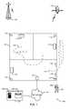
- FIG. 1illustrates an example system for collecting media exposure information and an example area in which audience members may be exposed to media presentations.
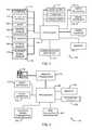
- FIG. 2is a block diagram of the example personal portable metering device of FIG. 1 .
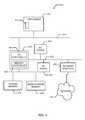
- FIG. 3is a block diagram of an example base unit for use in the system of FIG. 1
- FIG. 4is a block diagram of an example processor system that may be used to implement portions of the system of FIG. 1 .
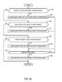
- FIG. 5is a flow diagram of an example method that may be used to collect exposure information and audience member location information.
- FIG. 6is a flow diagram of an example method that may be used to collect and analyze audience member location information and audience member motion information to monitor audience member behaviors.
- FIGS. 7A , 7 B, and 7 Care flow diagrams of an example method that may be used to collect and analyze media exposure information and audience member location information.
- FIG. 8is a flow diagram of an example method that may be used to credit a media presentation as being consumed based on exposure information and audience member behavior information.
- FIG. 9Ais a flow diagram of an example method that may be used to determine an audience member's compliance with PPM carrying/wearing requirements.
- FIG. 9Bis a flow diagram of another example method that may be used to determine an audience member's compliance with PPM carrying/wearing requirements.
- FIG. 9Cis a flow diagram of an example method that may be used to implement one or more power management processes in connection with the example methods of FIGS. 9A and 9B .
- FIG. 10is a flow diagram of another example method that may be used to determine an audience member's compliance with PPM carrying/wearing requirements.
- FIG. 11is a flow diagram of an example method that may be used to inform an audience member via a telephone that PPM usage is not compliant with PPM usage requirements.
- FIG. 12is a flow diagram of an example method that may be used to control a compliance status device based on the compliance status of each audience member in a household.
- FIG. 13is a flow diagram of an example method that may be used to determine if PPM usage is compliant with PPM usage requirements.
- FIG. 14illustrates an example PPM smartphone.
- FIG. 15is a detailed view of the example compliance status device of FIG. 1 .
- FIG. 16illustrates an example identification tag.
- the example methods and apparatus described hereinmay be used to analyze the motions, movements, locations, and/or behaviors of audience members in the course of their exposure to media sources or media presentations to aid in determining whether such media presentations were actually consumed by the audience members.
- the methods and apparatus described hereinmay be used to determine if audience members are complying with PPM carrying/wearing requirements or PPM usage requirements.
- information about the motion, the movements, and the locations of an audience member while exposed to a media presentationmay be used to aid in determining whether the audience member was sufficiently attentive to the presentation, to credit the presentation with consumption by the audience member, and to aid in determining whether the audience member is complying with PPM carrying/wearing requirements.
- the nature of an audience member's movementsmay indicate whether the audience member is distracted, inattentive, (likely) sleeping, not complying with the PPM wearing/carrying requirements, exercising, moving too quickly to be consuming the presentation, etc.
- the example methods and apparatus described hereinmay be implemented using, for example, personal portable meters (PPMs) worn or carried by audience members and location information systems (e.g., a global positioning system (GPS), RF towers/transceivers for triangulation, etc.), and may be used to collect audience member movement information and/or media exposure information and to analyze such movement and/or exposure information. Additionally, the movement and/or exposure information may be used to determine the behavior of an audience member to determine if the audience member is sufficiently exposed to media presentations. In this manner, media presentations (e.g., audio, video, still images, Internet information, computer information, etc.) may be given appropriate media consumption credit.
- PPMspersonal portable meters
- location information systemse.g., a global positioning system (GPS), RF towers/transceivers for triangulation, etc.
- GPSglobal positioning system
- the movement and/or exposure informationmay be used to determine the behavior of an audience member to determine if the audience member is sufficiently exposed to media presentations.
- media presentationse.
- example methods and apparatusare described herein with respect to an example geographic area 100 , which includes indoor and outdoor regions, that is shown in FIG. 1 as being associated with a household 102 .
- example methods and apparatus described hereinmay be used in any area or environment.
- Location informationmay include, for example, geographic, global, or position coordinates that, when analyzed, may be used to determine the movements of a person or an audience member from one location to another.
- location informationmay be collected, obtained, generated, etc. using any suitable location detection devices, location detection systems, and/or location detection techniques. Specifically, the location detection devices described below may be worn or otherwise carried by a person or audience member.
- the location detection systems disclosed in U.S. Application Ser. No. 60/613,646 and U.S. Application Ser. No. 60/614,939may also be used to detect location information.
- Motion informationmay include, for example, body displacement measurements or motion measurements associated with the relatively small movements or motion of an audience member's body. Motion information may be used to analyze the body movements of an audience member as the audience member consumes media. Body movements may include shifting or fidgeting while a person sits on a couch and passively consumes media. Body movements may also include, for example, dance movements, exercise movements, and/or any other body movements of a person, at least some of which may be the result of the person actively participating in activities (e.g., exercising, cooking, etc.) associated with the media program. As described in greater detail below, motion information may be collected, obtained, generated, etc. using any suitable motion detection devices and/or motion detection techniques. Specifically, the motion detection devices described below may be worn or carried by a person.
- Movement informationmay be generated using the location information and is indicative of an audience member's transition from one location (e.g., first location coordinates or a first room) to a substantially different location (e.g., second location coordinates or a second room). While motion information can be used to analyze a person's body movements while the person stays (e.g., stands, sits, etc.) in substantially the same location (e.g., at substantially the same location coordinates), movement information may be used to analyze when a person is moving between different rooms of a household or between substantially different spaces (e.g., substantially different location coordinates) within a room of the household.
- a person generating relatively large amounts of motionmay be very attentive to a television presentation because the person remains (e.g., sits, stands, etc.) at substantially the same location (e.g., in front of and/or exposed to the television) while generating the motion.
- a person generating relatively large amounts of movementmay be relatively less attentive to a television presentation because the person is likely moving away from the television or moving to spaces that decrease the person's exposure to the television.
- Location information and motion informationmay be continuously collected in indoor environments and/or outdoor environments via, for example, an example PPM 104 that may be carried or worn by an audience member 106 as shown in FIG. 1 .
- the example PPM 104may be implemented as a standalone device having a pager-like design.
- the example PPM 104may be integrated or jointly configured with a mobile telephone as described below in connection with FIG. 14 .
- the example methods and apparatusare described herein relative to the example PPM 104 and other devices (e.g., other PPMs, the PPM smartphone 1400 of FIG.
- location information and motion informationmay also be continuously collected based on identification tags or metering tags (e.g., the example identification tag 1600 of FIG. 16 ) or any other portable device (e.g., a tag, a meter, etc.) that may be worn or carried by a person.
- the identification tag 1600may be worn or carried by an audience member (e.g., the audience member 106 ) and used in combination with or instead of the example PPM 104 .
- the identification tag 1600may be used to detect the location of the audience member 106 by configuring a location information system (e.g., the base units 114 of FIGS.
- the PPM 104may collect media monitoring information while the location information system collects location or proximity information based on the identification tag 1600 .
- the example PPM 104may include one or more location detection devices and/or motion detection devices described below in connection with FIG. 2 that the PPM 104 may use to monitor the audience member 106 .
- the location detection devices and motion detection devicesmay be configured to enable the example PPM 104 to collect audience member location information and/or motion information in indoor environments and/or outdoor environments. In this manner, when an audience member moves among indoor areas and outdoor areas a substantially continuous location/motion history may be tracked or logged for each audience member and subsequently analyzed to develop movement information.
- Media monitoring informationmay include any information associated with media that is consumed (e.g., viewed, listened to, interacted with, etc.) by an audience member.
- Media presentationsmay include, for example, television programming, radio programming, movies, songs, advertisements, Internet information, and/or any other video information, audio information, still image information, and computer information to which a person may be exposed.
- Media monitoring informationmay be generated based on, for example, audio codes, signatures, radio frequency (RF) codes, and/or any other codes, information, or identifiers that may be extracted from or otherwise associated with a media presentation to which an audience member is exposed.
- RFradio frequency
- the PPM 104may tag media monitoring information with respective media location information to generate movement-annotated media monitoring information.
- the PPM 104may substantially continuously combine time-stamped media monitoring information with time-stamped location information that corresponds to the locations at which the PPM 104 collected the time-stamped media monitoring information. In this manner, subsequent analyses can be used to determine if the audience member 106 was compliant with the usage requirements or guidelines of the PPM 104 and to determine the locations at which the audience member 106 was exposed to particular media.
- time-stamped media monitoring informationmay be combined with time-stamped location information in a post collection process.
- time-stamped media monitoring information and time-stamped location informationmay be stored within a memory (e.g., the memory 204 of FIG. 2 ) of the PPM 104 or may be stored in a storage device that is separate from the PPM (e.g., another information processing system) and may then be combined, joined, or otherwise interrelated in a subsequent process to generate location-annotated media monitoring information.
- Other information with which the collected information may be annotatedincludes, for example, audience identification information.
- Movement information and media monitoring informationmay be used to better determine how to credit an exposure to a media presentation. For example, movement information and media monitoring information may be analyzed to determine the behaviors of audience members during their exposure to media presentations. The audience member behaviors may then be analyzed to determine when and how much credit is to be awarded or given to a media presentation for a given exposure.
- Media exposure creditsare typically used to measure or quantify the quantity of exposures of a media presentation to one or more audience members.
- Traditional methods for measuring media consumptiontypically track or log the media presentations to which an audience member is exposed and award media exposure credit to a media source or presentation when an audience member is in the vicinity of that media presentation or, more generally, within a distance of the media presentation at which the audience member is likely able to consume the media. However, these traditional methods may produce inconsistent or inaccurate results if the audience member is in the vicinity of a media presentation, but is not sufficiently attentive (e.g., the audience member is sleeping, distracted, etc.) during exposure to the media presentation to credit with actual consumption.
- the example methods and apparatus described hereinmay be used to credit media presentations by detecting the attentiveness, reactions, direction of movement, etc. of audience members exposed to the presentations.
- the television program or television programs to which the audience member 106 is exposedmay only be given partial credit.
- the example methods and apparatusmay be used to determine that the audience member 106 has a relatively higher level of attentiveness if the audience member 106 moves away from a living room television and walks into the kitchen or another room for only a brief amount of time than if the audience member 106 were to move to an office or another room for a relatively longer amount of time.
- a television media presentationmay then be given relatively more exposure credit when the attentiveness of the audience member 106 is indicated as relatively higher.
- the radio program or radio programsmay be given full credit because effective consumption of the radio program may only require that the audience member be within audible range of the radio program.
- location information and motion informationmay be analyzed to detect small movements or motion of an audience member to determine if the audience member is sleeping, distracted, not adequately exposed to or otherwise not sufficiently attentive to a media source or media presentation. These analyses may be performed as a substantially real time process or as a post process. In either case, the analyses may be used to determine the manner in which credit should be awarded to each exposure to a media presentation.
- the example methods and apparatus described hereinmay also be used to credit a media presentation based on the manner in which and the degree to which audience members are compliant to PPM carrying/wearing (usage) requirements or guidelines. For example, motion information or location information associated with the PPM 104 indicating that the PPM 104 was stationary for an excessively long period of time may be used to conclude that the PPM 104 was not likely worn/carried by the audience member 106 during that period of time. If the PPM 104 was not worn for a sufficiently lengthy period of time, media monitoring information collected during that period of time may be disregarded.
- notice of non-compliant behaviormay be sent to the audience member 106 in response to determining non-compliance of the audience member's 106 usage of the PPM 104 . The notice may be sent via any message delivery means such as, for example, mail, email, phone, and/or via a display or audio alert of the PPM 104 .
- the results of the analysesmay be used to determine if the audience member 106 should be prompted for information.
- the audience member 106may be prompted via the PPM 104 to provide feedback via the PPM 104 regarding whether they are consuming a detected media presentation or are merely in the vicinity of the detected media presentation.
- the audience member 106may be prompted to express approval or disapproval of a media presentation, or may submit his or her approval or disapproval without being prompted.
- the audience member 106may alternatively or additionally be prompted for other information such as, for example, their subjective rating of one or more media presentations, whether they would view the media presentation or a related media presentation again, the number of unmonitored individuals who are also present and consuming the media presentation, etc. Additionally, or instead, the prompting may instruct the audience member 106 to move or shake the PPM 104 so that the motion detection devices residing within the PPM 104 are activated. The activation of the motion detection devices may cause information concerning compliance of wearing/carrying requirements to be logged.
- the PPM 104need not necessarily be carried by the audience member 106 , rather the PPM 104 need only be within arms length of the audience member 106 (or at least sufficiently close to the audience member 106 ) to accurately capture information about the audience member's exposure to media presentations.
- example methods and apparatus described hereinmay use location information, motion information, and/or the media monitoring information to analyze audience members' reactions to media presentations and/or to analyze audience members' activities during media presentations.
- the amount or type of credit given to a media presentationmay depend on activities related to or portrayed by a media presentation. Activities of interest may include cooking while watching a cooking show, exercising while watching a fitness show, dancing while listening to music, etc.
- behavior recognition techniquesmay be used to recognize media consumption related behaviors of audience members. More specifically, behavior recognition techniques may be used to recognize repeated sequences of events that audience members often perform in a typical day during their exposure to media presentations. Behavior recognition techniques may include event pattern recognition techniques (i.e., event sequence recognition techniques) that involve detecting patterns in sequences of events within daily routines of one or more audience members. For example, on a typical work day, a sequence of events for one or more audience members may involve stopping for gasoline followed by purchasing breakfast at a drive-thru while commuting to work. Such sequences of events may be recognized as typical morning routines performed by a certain audience member(s). An example use of behavior recognition techniques may involve analyzing demographic information of audience members and forming general conclusions about demographic groups related to media consumption. Another example use of behavior recognition techniques involves differentiating between behaviors of an audience member in response to advertising and behaviors of an audience member related to a usual routine.
- event pattern recognition techniquesi.e., event sequence recognition techniques
- the household 102 and the audience member 106 wearing the PPM 104are located within the example geographic area 100 .
- the PPM 104may be used to collect location information, motion information, and media monitoring information within the household 102 , outside of the household 102 , within structures other than the household 102 , outdoors, etc.
- the PPM 104may be configured to substantially continuously generate, obtain, and/or collect media monitoring information, location information, and motion information. As described in greater detail below in connection with FIG. 2 , the PPM 104 may include one or more media detection devices used to detect presented media and to generate or collect media monitoring information or media-related data based on, for example, audio signals, visual signals, RF signals, infrared (IR) signals, etc. In addition, the PPM 104 may include one or more location or positioning devices that enable the PPM 104 to collect location or position information from one or more location information systems and/or to send location information to one or more location information systems.
- the example geographic area 100includes one or more location information systems that may be used to communicate location information to/from the PPM 104 .
- the location information systemsmay be implemented using, for example, one or more radio frequency (RF) transceiver towers represented in FIG. 1 by the RF transceiver tower 108 and/or one or more satellites represented in FIG. 1 by a satellite 110 .
- RFradio frequency
- the interior environment of the household 102may include one or more location information systems described below.
- the PPM 104may collect media monitoring information (e.g., ancillary codes, signatures, etc.) associated with any media (e.g., video, audio, movies, music, still pictures, advertising, etc.) to which the audience member 106 is exposed.
- media monitoring informatione.g., ancillary codes, signatures, etc.
- the PPM 104may be configured to obtain audio codes, generate or collect signatures, etc. that may be used to identify video programs (e.g., DVD movies, television programming, etc.), audio programs (e.g., CD audio, radio programming, etc.), etc.
- the household 102includes a plurality of media delivery centers 112 , each of which may include a media delivery device such as, for example, a television, a radio, etc.
- the PPM 104may collect media monitoring information associated with media presented or delivered by one or more of the media delivery centers 112 and to which the audience member 106 may be exposed.
- the PPM 104may be configured to receive audio codes and/or RF codes associated with other forms of media such as, for example, billboards (not shown) or any other form of publicly viewable advertising or media.
- each billboardmay include an audio broadcasting device and/or an RF broadcasting device configured to emit a billboard code that uniquely identifies that billboard. If the PPM 104 is proximate to a billboard, the PPM 104 may obtain the billboard code as media monitoring information, thereby indicating that the audience member 106 was exposed to the billboard.
- the PPM 104may be configured to obtain direction information via, for example, an electronic compass, and log the direction in which the audience member 106 was facing or traveling so that subsequent data analyses may determine if the audience member 106 was likely facing the billboard.
- Location information collected by the PPM 104may be used to generate movement information and/or to analyze the movements of the audience member 106 .
- movement informationmay be stored as a plurality of location coordinates or location information that may be converted to movement information during subsequent processing by generating movement paths that indicate or track the movements of an audience member.
- the PPM 104may also include motion detection devices as described below in connection with FIG. 2 . Motion detection devices may be used to generate motion information associated with the relatively small movements (e.g., shifting, fidgeting, exercising, etc.) of an audience member's body.
- the RF transceiver tower 108may be used in combination with any RF communication technology such as, for example, a cellular or mobile communication technology (e.g., GSM, CDMA, TDMA, AMPS, etc.)
- the RF transceiver tower 108may be configured to transmit or broadcast position information and/or any type of signal that may be used by the PPM 104 to generate location information.
- the RF transceiver tower 108may transmit information having geographic location information and time codes. More specifically, the RF transceiver tower 108 may be associated with a particular or unique set of geographic location coordinates (i.e., geographic location information), that define or indicate the location of the RF transceiver tower 108 within a global positioning grid.
- the time codesmay be associated with a time at which a particular signal is transmitted by the RF transceiver tower 108 .
- the geographic location information and the time codes received from a plurality of RF transceiver towersmay be used by the PPM 104 to perform triangulation processes to determine the location(s) of the PPM 104 . Triangulation processes are well known in the art and, thus, are not described further herein.
- the RF transceiver tower 108is depicted as being located in an outdoor environment, the PPM 104 may include location technologies that communicate with the RF transceiver tower 108 when the PPM 104 is located within indoor environments (e.g., within the household 102 ) or outdoor environments.
- the satellite 110may also be used to communicate location information to/from the PPM 104 .
- the satellite 110may be used to implement any satellite positioning system (SPS) such as, for example, the global positioning system (GPS) that continuously broadcasts position-related information.
- SPSsatellite positioning system
- GPSglobal positioning system
- the PPM 104may receive the position-related information from the satellite 110 to determine movement information associated with the location(s) of the PPM 104 .
- an example location information systemincludes a plurality of base units 114 .
- the base units 114may include one or more location-based technologies, some of which are described below in connection with FIG. 3 and may be configured to work cooperatively with the PPM 104 to substantially continuously generate location information associated with the location of the PPM 104 as the audience member 106 moves among various areas within or around the household 102 .
- Example movement informationis shown in FIG. 1 as a first movement path 116 and a second movement path 118 .
- the first movement path 116is an example of movement information that is collected as, for example, the audience member 106 moves from one room to another.
- the second movement path 118is an example of movement information that is collected as the audience member 106 moves from the inside of the household 102 to a location outside of the household 102 .
- the example movement paths 116 and 118may be generated using location information collected by the PPM 104 in combination with any one or more suitable location information systems (e.g., the RF transceiver tower 108 , the satellite 110 , the base units 114 , etc.).
- the location information used to generate the movement path 116may be generated using information received from the RF transceiver towers 108 , the base units 114 , or a combination thereof.
- the location information used to generate the movement path 118may include location information generated using location information systems that function for indoor use and/or outdoor use.
- One such location information systemmay be, for example, the RF transceiver tower 108 .
- location information associated with the movement path 118may be generated using a combination of location information systems such as, for example, a first location information system that functions primarily or only in indoor environments and a second location information system that functions primarily or only in outdoor environments.
- the first location information system for indoor usemay be, for example, the base units 114 and the second location information system may be, for example, the satellite 110 .
- Using two location information systemsmay require a handoff process to ensure that the PPM 104 transitions substantially seamlessly from working with one location information system to working with another.
- An example handoff processmay include a software routine that continuously searches for signals from both location information systems and works with the location information system providing the strongest signal (e.g., the signal having the highest power level).
- Other software and/or circuitrymay provide hysteresis to enable minimum/maximum threshold levels of signal strength to be used to prevent the PPM 104 from continuously and/or rapidly switching back and forth between location information systems.
- An example compliance status device 119may be configured to obtain compliance status from the PPM of each audience member in the household 102 and display the compliance status.
- the compliance status device 119includes a display that may be implemented using, for example, a plurality of LEDs. Each of the LEDs may correspond to one of the audience members. Each LED may be configured to, for example, glow red when the corresponding audience member is non-compliant and glow green when the corresponding audience member is compliant.
- Each PPMmay be configured to wirelessly transmit compliance status information directly to the compliance status device 119 and/or each PPM may be configured to transmit compliance status information to a central collection facility (e.g., the central facility 122 described below), which may then communicate the compliance status information to the compliance status device 119 .
- the compliance status device 119may also be communicatively coupled to a home processing system (e.g., the home processing system 121 described below).
- each of the plurality of compliance status devicesmay be located in each room of the household 102 .
- Each compliance status devicemay be configured to indicate via, for example, LEDs, when an audience member is in the room corresponding to that compliance status device.
- An example implementation of the compliance status device 119is illustrated in greater detail in FIG. 15 .
- the compliance status device 119is depicted as being separate from the home processing system 121 , the compliance status device 119 and/or the operations, processes, or function of the compliance status device 119 may be implemented using the home processing system 121 .
- a separate compliance status device(e.g., the compliance status device 119 ) is not necessary, and the home processing system 121 may be configured to display compliance status information of household members via, for example, a graphical user interface and communicate the compliance status information to the central facility 122 .
- the compliance status device 119may be implemented using any other processing system or apparatus (e.g., one or more of the base units 114 , a security system 120 , etc.).
- a security system 120may be configured to determine when audience members of the household 102 leave or enter the household 102 .
- the security system 120may be communicatively coupled to door sensors (not shown) that communicate signals to the security system 120 indicating that a door has been opened or that a person has entered or left the household 102 .
- the door sensorsmay be implemented using magnetic reed switches and/or optical sensors.
- a magnetic reed switchmay be configured to indicate that a door is open and an optical sensor may be configured to indicate that an audience member has left or entered the household 102 .
- the security system 120may be communicatively coupled to the compliance status device 119 and/or a home processing system (e.g., the home processing system 121 described below).
- a home processing system 121may be configured to communicate with the PPM 104 and/or the base units 114 .
- the home processing system 121may be communicatively coupled to one or more docking stations (not shown) configured to receive the PPM 104 and communicatively couple the PPM 104 to the home processing system 121 .
- the audience member 106may periodically (e.g., nightly) place the PPM 104 in a docking station to enable the home processing system 121 to obtain collected media monitoring information, location information, motion information, and/or any other information stored in the PPM 104 .
- the PPM 104may communicate with the base units 114 via wireless and/or hardwired communications and may periodically communicate collected information to the home processing system 121 via one or more of the base units 114 .
- the home processing system 121is communicatively coupled to a central facility 122 via a network 124 .
- the central facility 122is remotely located from the household 102 and is communicatively coupled to the household 102 and other monitored sites (e.g., other households) via the network 124 .
- the central facility 122may obtain media consumption data, media monitoring data, location information, motion information, and/or any other monitoring data that is collected by various media monitoring devices such as, for example, the PPM 104 .
- the central facility 121includes a server 126 (i.e., a central processor system) and a database 128 that may be implemented using any suitable memory and/or data storage apparatus and techniques.
- the server 126may be implemented using, for example, a processor system similar or identical to the example processor system 410 depicted in FIG. 4 that is configured to store information collected from the PPM 104 in the database 128 and to analyze the information.
- the server 126may be configured to generate calibration information for the PPM 104 and/or other PPMs based on audio information or audio samples collected during an acoustic characterization process or calibration process performed within the household 102 .
- the network 124may be used to communicate information between the central facility 122 and devices or apparatus in the monitored household 102 .
- the network 124may be communicatively coupled to the base units 114 , the PPM 104 , and/or the home processing system 121 .
- the network 124may be implemented using any suitable communication interface including, for example, telephone lines, a cable system, a satellite system, a cellular communication system, AC power lines, etc.
- FIG. 2is a block diagram of the example PPM 104 of FIG. 1 .
- the PPM 104may be used to monitor the media consumption activities of an audience member (e.g., the audience member 106 of FIG. 1 ) in addition to location information and motion information associated with those media consumption activities.
- the PPM 104includes electronic components configured to detect and collect media monitoring information, location information, and motion information and communicates the information to the home processing system 121 and/or the central facility 122 ( FIG. 1 ) for subsequent analyses. As shown in FIG.
- the PPM 104includes a processor 202 , a memory 204 , a communication interface 206 , a plurality of media monitoring information sensors 208 , a plurality of location and motion sensors 210 , a plurality of audience alerts 212 , an input interface 214 , a visual interface 216 , and a timer/counter 217 , all of which are communicatively coupled as shown.
- the processor 202may be any processor suitable for controlling the PPM 104 and managing or processing monitoring data related to detected media consumption or presentation information, location information, and/or motion information.
- the processor 202may be implemented using a general purpose processor, a digital signal processor, or any combination thereof.
- the processor 202may be configured to perform and control various operations and features of the PPM 104 such as, for example, setting the PPM 104 in different operating modes, controlling a sampling frequency for collecting media monitoring information, location information, and motion information, managing communication operations with other processor systems (e.g., the base units 114 , the home processing system 121 , the server 126 of FIG. 1 ), selecting location information systems (e.g., the RF transceiver tower 108 , the satellite 110 , and the base units 114 ), etc.
- other processor systemse.g., the base units 114 , the home processing system 121 , the server 126 of FIG. 1
- selecting location information systemse.g., the RF transceiver tower
- the memory 204may be used to store collected media monitoring information, program instructions (e.g., software, firmware, etc.), program data (e.g., location information, motion information, etc.), and/or any other data or information required to operate the PPM 104 .
- the processor 202may time stamp the acquired information and store the time-stamped information in the memory 204 .
- the memory 204may be implemented using any suitable volatile and/or non-volatile memory including a random access memory (RAM), a read-only memory (ROM), a flash memory device, a hard drive, an optical storage medium, etc.
- the memory 204may be any removable or non-removable storage medium.
- the communication interface 206may be used to communicate information between the PPM 104 and other processor systems including, for example, the base units 114 , the home processing system 121 , and/or the server 126 of FIG. 1 .
- the communication interface 206may be implemented using any type of suitable wired or wireless transmitter, receiver, or transceiver such as, for example, a Bluetooth® transceiver, an 802.11 (i.e., Wi-Fi®) transceiver, a cellular communications transceiver, an optical communications transceiver, etc.
- the media monitoring information sensors 208include an acoustic signal sensor 218 , and optical sensor 220 , and an RF sensor 222 .
- the example PPM 104via the acoustic signal sensor 218 , the optical sensor 220 , and the RF sensor 222 , observes the environment in which the audience member 106 is located and monitors for media presentation and/or signals associated with media presentations.
- the example PPM 104logs or stores a representation of the media content in the memory 204 and/or identifies the content, along with the time at which the content is detected.
- the acoustic signal sensor 218may be, for example, a condenser microphone, a piezoelectric microphone or any other suitable transducer capable of converting audio or acoustic signal information into electrical information.
- the acoustic signal sensor 218may be configured to detect acoustic signals in the human audible range or non-human audible range (e.g., ultrasound acoustic signals).
- the optical sensor 220may be, for example, a light sensitive diode, an IR sensor, a complimentary metal oxide semiconductor (CMOS) sensor array, a charge-coupled diode (CCD) sensor array, etc.
- the RF sensor 222may be, for example, a Bluetooth® transceiver, an 802.11 transceiver, an ultrawideband RF receiver, and/or any other RF receiver and/or transceiver. While the example PPM 104 of FIG. 1 includes the acoustic signal sensor 218 , the optical sensor 220 , and the RF sensor 222 , the example PPM 104 need not include all of the sensors 218 , 220 , and 222 .
- the acoustic signal sensor 218is sufficient to identify audio/video or program content via program characteristics, such as signatures or, if they are present, audio codes.
- the optical sensor 220is sufficient to identify program content via program characteristics, such as signatures or, if present, video codes.
- one particularly advantageous exampleincludes the acoustic signal sensor 218 and the optical sensor 220 .
- the location and motion sensors 210are configured to detect location-related information and/or motion-related information and to generate corresponding signals that are communicated to the processor 202 . More specifically, the location and motion sensors 210 may include a motion sensor 224 , a satellite positioning system (SPS) receiver 226 , an RF location interface 228 , and a compass 230 .
- SPSsatellite positioning system
- location and motion sensors 210may be configured to receive location-related information (e.g., encoded information, pluralities of fragmented information, etc.) and to perform any processing necessary to convert the received information to location information that indicates the location at which the PPM 104 is located.
- location informationmay be derived using triangulation techniques, whereby the PPM 104 may receive RF signals from three or more RF transmitters (e.g., three or more of the base units 114 of FIG. 1 ). In this case, a single RF signal from any one RF transmitter may be useless for generating location information.
- the location informationmay be generated by triangulating or processing a combination of RF signals from a plurality of RF transmitters.
- location and motion sensors 210may be configured to process received location-related signals to generate location information and others of the location and motion sensors 210 may be configured to process the received location-related signals in combination with software executed on the processor 202 to generate location information. Still others of the location and motion sensors 210 may communicate any received information to the processor 202 for processing.
- the motion sensor 224may be used to detect relatively small body movements of an audience member (e.g., the audience member 106 ), generate motion information related to the body movements, and communicate the motion information to the processor 202 .
- the motion sensor 224may be implemented using any suitable motion detection device such as, for example, a mercury switch, a trembler, a piezo-gyroscope integrated circuit (IC), an accelerometer IC, etc.
- the motion information generated by the motion sensor 224may be used to determine if the audience member 106 is wearing or carrying the PPM 104 .
- the motion informationmay be used to determine if the audience member 106 is consuming (e.g., paying attention to) a media presentation. For example, if the motion information indicates that the audience member 106 is substantially motionless, an analysis of such motion information may indicate that the audience member 106 was likely sleeping and, thus, not consuming a media presentation.
- the motion informationindicates that the audience member 106 is generating an extraordinary amount of motion information, an analysis of such motion information may indicate that the audience member is either participating with the media presentation (e.g., dancing, exercising, cooking, etc.) or is moving around too much to adequately consume the media presentation. In either case, analyses of the motion information may be used to prompt the audience member 106 via one of the audience alerts 212 to confirm if the audience member 106 is actively consuming the media presentation.
- the SPS receiver (SPSR) 226may be implemented using, for example, a GPS receiver and may be configured to generate location information based on encoded GPS signals received from GPS satellites. In general, the SPS receiver 226 may be used by the PPM 104 to collect location information in outdoor environments.
- the RF location interface 228may be implemented using a receiver or a transceiver and may be used to receive location-related signals or information from location information systems such as, for example, the RF transceiver tower 108 and/or the base units 114 .
- the RF location interface 228may also be configured to broadcast location-related information such as, for example, time-stamped PPM identification codes.
- the time-stamped PPM identification codesmay be received by, for example, three or more of the base units 114 , which may process the codes cooperatively using triangulation techniques to determine the location of the PPM 104 .
- the base units 114may communicate to the home processing system 121 the received time-stamped PPM identification codes along with information relating to the time at which the codes were received by each of the base units 114 .
- the home processing system 121may then determine the location of the PPM 104 based on this information.
- the RF location interface 228may be implemented using any suitable RF communication device such as, for example, a cellular communication transceiver, a Bluetooth® transceiver, an 802.11 transceiver, an ultrawideband RF transceiver, etc.
- the RF location interface 228may be implemented using only an RF receiver or only an RF transmitter. Examples of known location-based technologies that may be implemented in cooperation with the RF location interface 228 include the Ekahau Positioning EngineTM by Ekahau, Inc. of Saratoga, Calif., an ultrawideband positioning system by Ubisense, Ltd. of Cambridge, United Kingdom, and the Cricket Indoor Location System developed at Massachusetts Institute of Technology (“MIT”) of Cambridge, Mass. and described in the technical paper, “The Cricket Indoor Location System”, by Nissanka B. Priyantha.
- the Ekahau Positioning EngineTMmay be configured to work with a plurality of standard wireless communication protocol base stations (e.g., 802.11, Bluetooth®, etc.) to broadcast location-related information.
- a suitable wireless communication protocol devicee.g. 802.11, Bluetooth®, etc.
- the Ekahau Positioning EngineTMmay be used to generate location information.
- location-related informationmay be transmitted from the base units 114 , received by the RF location interface 228 , and used to generate location information using Ekahau Positioning software offered by Ekahau, Inc.
- the Ubisense ultrawideband systemmay be used by communicatively coupling an ultrawideband transmitter to each of the base units 114 ( FIG. 1 ) and implementing the RF location interface 228 using an ultrawideband receiver.
- the RF location interface 228can receive ultrawideband signals having location-related information that are broadcast from the base units 114 and the PPM 104 can generate location information based on the received ultrawideband signals.
- the Cricket Indoor Location Systemmay be implemented by providing an ultrasound transmitter (e.g., the acoustic signal transmitter 316 ) to each of the base units 114 ( FIG. 1 ) and an ultrasound receiver (e.g., the acoustic signal sensor 218 ) to the PPM 104 .
- the base units 114can emit an RF signal via the RF location interface 306 and a corresponding ultrasound signal via the acoustic signal transmitter 316 .
- the RF signalincludes including a room identifier and/or position coordinates pertaining to the location of the transmitting base unit 114 .
- the PPM 104can then receive the RF signal via the RF location interface 228 and the ultrasound signal via the acoustic signal sensor 218 .
- the RF signal and the ultrasound signaltravel at different propagation speeds and, thus, the PPM 104 will receive the signals at different times. Specifically, the RF signal travels at the speed of light and the ultrasound signal travels at the speed of sound.
- the PPM 104can determine the time difference between the reception time of the RF signal and the reception time of the ultrasound signal to determine its distance from the transmitting base unit 114 .
- the PPM 104can use the compare time differences between RF signal receptions and respective ultrasound signal receptions to determine the closest base unit 114 .
- the PPM 104can then select the room identifier and/or the position coordinates of the signal pairs corresponding to the base unit 114 that is in closest proximity to the PPM 104 .
- the compass 230may be implemented using a magnetic field sensor, an electronic compass IC, and/or any other suitable electronic circuit.
- the compass 230may be used to generate direction information, which may be useful in determining the direction in which an audience member (e.g., the audience member 106 ) is facing.
- the direction informationmay be used to determine if a person is facing a television to enable consumption of a television program.
- the direction informationmay also be used to determine if a person is facing, for example, a billboard advertisement so that when the PPM 104 receives an RF identification signal corresponding to the billboard advertisement and location information indicating that the audience member 106 is in front of the billboard, the direction information from the compass 230 may be used to determine if the audience member 106 is facing the billboard. In this manner, the billboard content may be credited appropriately for being consumed by a person.
- DRM®Dead-Reckoning Module
- the DRM®is configured to enable generation and/or collection of location information within buildings (e.g., the household 102 ) and in outdoor environments. In general, when used outdoors, the DRM® uses GPS technology to collect location information. When used indoors, the DRM® uses, among other components, a compass (e.g., the compass 230 ) and an accelerometer (e.g., the motion sensor 224 ) to generate location information.
- a compasse.g., the compass 230
- an accelerometere.g., the motion sensor 224
- the plurality of audience alerts 212may be used to capture the attention of audience members (e.g., the audience member 106 of FIG. 1 ) to, for example, provide information to audience members and/or request input.
- audience memberse.g., the audience member 106 of FIG. 1
- the audience member 106may be prompted via one or more of the audience alerts 212 to indicate via the input interface 214 whether the audience member is consuming the detected media presentation or is merely in the vicinity of the detected media presentation.
- the audience member 106may be prompted to express approval or disapproval of a media presentation, or may submit his or her approval or disapproval without being prompted.
- any input informationcan also be used to credit a program with active consumption assuming that there is a positive correlation between opinion formulation and consumption (e.g., assuming people tend to formulate opinions on information that has actually been consumed and are less likely to formulate opinions on information to which they have merely been exposed).
- the PPM 104may also include the input interface 214 , which may be used by an operator (e.g., the audience member 106 ) to input information to the PPM 104 .
- the input interface 214may include one or more buttons or a touchscreen that may be used to enter information, set operational modes, turn the PPM 104 on and off, etc.
- the input interface 214may be used to enter PPM settings information, audience member identification information, etc.
- the PPM 104may further include the visual interface 216 , which may be used in combination with the input interface 214 to enter and retrieve information from the PPM 104 .
- the visual interface 216may be implemented using a liquid crystal display (LCD) that, for example, displays detailed status information, location information, configuration information, calibration information, etc.
- the visual interface 216may include light-emitting diodes (LEDs) that convey information including, for example, status information, operational mode information, etc.
- LEDslight-emitting diodes
- the timer/counter 217may be used to generate timer events that are communicated to the processor 202 . Timer events may be used to, for example, wake-up the PPM 104 from a shut-down state, powered-down state, a power-saving mode state, etc.
- the timer/counter 217may be configured to generate a timing event after a particular amount of time has elapsed or at a particular time of day. The amount of time or time of day may be set by, for example, configuring registers in the timer/counter 217 .
- FIG. 3is a block diagram of one of the example base units 114 of FIG. 1 .
- the example base units 114may be used to communicate information to the PPM 104 , the home processing system 121 , and/or the central facility 122 of FIG. 1 .
- the example base unit 114includes a processor 302 , a memory 304 , an RF location interface 306 , a PPM interface 308 , a remote transceiver 310 , an input interface 312 , and a visual interface 314 , and an acoustic signal transmitter 316 , all of which may be communicatively coupled as shown.
- the processor 302may be used to control and perform various operations or features of the base unit 114 and may be implemented using any suitable processor, including any general purpose processor, digital signal processor, or any combination thereof.
- the processor 302may be configured to receive location information, motion information, and/or media monitoring information from the PPM 116 .
- information collected by the PPM 104may be stored in the memory 204 ( FIG. 2 ).
- the collected informationmay be stored in the memory 304 and communicated to the home processing system 121 and/or the central facility 122 .
- the processor 302may also be configured to control communication processes that occur between the base unit 114 and other processing systems (e.g., the PPM 104 , the home processing system 121 , and the server 126 ). For example, the processor 302 may provide location-related information to PPMs via the RF location interface 306 . In addition, the processor 302 may control the reception of media monitoring information, location information, motion information, etc. from the PPM 104 via the PPM transceiver 308 and store the information in the memory 304 . The processor 302 may then cause the remote transceiver 310 to communicate the monitoring data to, for example, the home processing system 121 ( FIG. 1 ) and/or the central facility 126 ( FIG. 1 ) via the remote transceiver 310 .
- the memory 304is substantially similar or identical to the memory 204 ( FIG. 2 ) and may be used to store program instructions (e.g., software, firmware, etc.), data (e.g., location information, motion information, media monitoring information, etc.), and/or any other data or information associated with the base unit 114 .
- program instructionse.g., software, firmware, etc.
- datae.g., location information, motion information, media monitoring information, etc.
- any other data or information associated with the base unit 114e.g., location information, motion information, media monitoring information, etc.
- the RF location interface 306may be implemented using a transmitter, a receiver, or a transceiver and configured to transmit and/or receive location-related information and may be configured to communicate with the RF location interface 228 ( FIG. 2 ) of the PPM 104 .
- the RF location interface 306may transmit location-related codes to the PPM 104 , which may receive encoded location-related codes from various base units to determine location coordinates indicative of the location of the PPM 104 .
- the RF location interface 306may receive location-related codes from the PPM 104 and, as described above, may work in cooperation with other base units and/or the home processing system 121 to determine the location of the PPM 104 .
- the RF location interface 306may be implemented using any suitable RF communication device such as, for example, a cellular communication transceiver, a Bluetooth® transceiver, an 802.11 transceiver, an ultrawideband RF transceiver, etc.
- the RF location interface 306may be used in combination with any of the known location-based technologies described above (e.g., the Ekahau Positioning EngineTM by Ekahau, Inc. and the ultrawideband positioning system by Ubisense, Ltd.).
- the RF location interface 306may be configured to receive and/or transmit any form of location-related information including location coordinates and any other information associated with known location-based technologies.
- the PPM interface 308is substantially similar or identical to the communication interface 206 of FIG. 2 and may be configured to communicate information between the base unit 114 and one or more PPMs (e.g., the PPM 104 of FIGS. 1 and 2 ).
- the PPM transceiver 308may be any wired or wireless transceiver such as, for example, a Bluetooth® transceiver, an 802.11 transceiver, an Ethernet transceiver, a UART, a cellular communication transceiver, etc.
- the base unit 114may also include the input interface 312 and the visual interface 314 , which may be substantially similar or identical to the input interface 214 and the visual interface 216 , respectively, of FIG. 2 .
- the acoustic signal transmitter 316may be configured to emit acoustic signals in the human audible range or non-human audible range (e.g., ultrasound signals). In some example implementations, the acoustic signal transmitter 316 may be used to emit audible alarms or chirps to be detected by the PPM 104 and/or by an audience member. In addition, the acoustic signal transmitter 316 may be configured to output ultrasound signals to be detected by the PPM 104 (e.g., detected by the acoustic signal sensor 218 of FIG. 2 ) to, for example, generate location information associated with the location of the PPM 104 within a particular environment (e.g., the household 102 ).
- a particular environmente.g., the household 102
- the remote transceiver 310may be used to communicate information between the base unit 114 and, for example, the home processing system 121 ( FIG. 1 ) and/or the central facility 122 ( FIG. 1 ).
- the remote transceiver 310may be communicatively coupled to the network 124 and may be implemented using any suitable wired or wireless communication transceiver including, for example, a telephone modem, a DSL modem, a cable modem, a cellular communication circuit, an Ethernet communication circuit, an 802.11 communication circuit, etc.
- the remote transceiver 310may be used to communicate media monitoring information (e.g., audio samples), location information, and/or motion information to the home processing system 121 and/or the central facility 122 via the network 124 .
- FIG. 4is a block diagram of an example processor system 410 that may be used to implement the apparatus and methods described herein.
- the processor system 410includes a processor 412 that is coupled to an interconnection bus 414 .
- the processor 412includes a register set or register space 416 , which is depicted in FIG. 4 as being entirely on-chip, but which could alternatively be located entirely or partially off-chip and directly coupled to the processor 412 via dedicated electrical connections and/or via the interconnection bus 414 .
- the processor 412may be any suitable processor, processing unit or microprocessor.
- the system 410may be a multi-processor system and, thus, may include one or more additional processors that are identical or similar to the processor 412 and that are communicatively coupled to the interconnection bus 414 .
- the processor 412 of FIG. 4is coupled to a chipset 418 , which includes a memory controller 420 and an input/output (I/O) controller 422 .
- a chipsettypically provides I/O and memory management functions as well as a plurality of general purpose and/or special purpose registers, timers, etc. that are accessible or used by one or more processors coupled to the chipset 418 .
- the memory controller 420performs functions that enable the processor 412 (or processors if there are multiple processors) to access a system memory 424 and a mass storage memory 425 .
- the system memory 424may include any desired type of volatile and/or non-volatile memory such as, for example, static random access memory (SRAM), dynamic random access memory (DRAM), flash memory, read-only memory (ROM), etc.
- the mass storage memory 425may include any desired type of mass storage device including hard disk drives, optical drives, tape storage devices, etc.
- the I/O controller 422performs functions that enable the processor 412 to communicate with peripheral input/output (I/O) devices 426 and 428 and a network interface 430 via an I/O bus 432 .
- the I/O devices 426 and 428may be any desired type of I/O device such as, for example, a keyboard, a video display or monitor, a mouse, etc.
- the network interface 430is communicatively coupled to the network 124 and may be, for example, an Ethernet device, an asynchronous transfer mode (ATM) device, an 802.11 device, a DSL modem, a cable modem, a cellular modem, etc. that enables the processor system 410 to communicate with another processor system.
- ATMasynchronous transfer mode
- memory controller 420 and the I/O controller 422are depicted in FIG. 4 as separate functional blocks within the chipset 418 , the functions performed by these blocks may be integrated within a single semiconductor circuit or may be implemented using two or more separate integrated circuits.
- FIGS. 5 through 9are flow diagrams that depict example methods.
- the example methods depicted in the flow diagrams of FIGS. 5 through 9may be implemented in software, hardware, and/or any combination thereof.
- the example methodsmay be implemented in software that is executed on the PPM 104 of FIGS. 1 and 2 , the base units 114 of FIGS. 1 and 3 , and/or the processor system 410 of FIG. 4 .
- the example methodsare described below as a particular sequence of operations, one or more operations may be rearranged, added, and/or removed to achieve the same or similar results.
- FIG. 5is a flow diagram of an example method that may be used to collect and analyze media monitoring information and location information.
- the example method of FIG. 5may be implemented using a PPM (e.g., the PPM 104 of FIG. 1 ).
- the PPM 104may be configured to collect location information, media monitoring information, and perform behavior analysis based on the collected information.
- the PPM 104receives a media signal (block 502 ).
- the media signalmay be an audio signal, a video signal, an RF signal, an image, etc.
- the PPM 104then generates media monitoring information (block 504 ) based on the media signal.
- the PPM 104generates location information (block 506 ).
- the location informationmay be generated by receiving location data from, for example, a location information system (e.g., the RF transceiver tower 108 , the satellite 110 , the base units 114 of FIG. 1 ) and/or a location detection system (e.g., the motion sensor 224 and the compass 230 of FIG. 2 used in combination with the DRM®) and performing a location generation algorithm (e.g., a triangulation algorithm) with the received location data.
- a location information systeme.g., the RF transceiver tower 108 , the satellite 110 , the base units 114 of FIG. 1
- a location detection system
- the PPM 104may then generate a timestamp (block 508 ) associated with the time at which the PPM 104 received the media signal and/or the time at which the PPM 104 received the location data.
- the media monitoring informationmay then be tagged with the location information and the timestamp (block 510 ), after which the location-annotated media monitoring information may be stored (block 512 ) in, for example, the memory 204 ( FIG. 2 ).
- Subsequent behavior analysesmay be performed (block 514 ) by, for example, the PPM 104 based on the location-annotated media monitoring information.
- An example method that may be used to perform behavior analysisis described in greater detail below in connection with FIG. 6 .
- the PPM 104may then determine if the collected information (e.g., the location-annotated media monitoring information) should be sent or communicated to a central processing system (e.g., the home processing system 121 or the server 126 of FIG. 1 ). For example, the PPM 104 may be configured to communicate the stored information based on predetermined time intervals (e.g., periodically) or based on a predetermined number of stored entries. If the stored information is not to be communicated to the central processing system, control is passed back to block 502 . Otherwise, the collected information is communicated to the central processing system (block 518 ), after which the process may be ended. Although not shown, following the operation of block 518 , control may be passed back to block 502 .
- a central processing systeme.g., the home processing system 121 or the server 126 of FIG. 1 .
- the PPM 104may be configured to communicate the stored information based on predetermined time intervals (e.g., periodically) or based on a pre
- FIG. 6is a flow diagram of an example method that may be used to analyze audience member location information and motion information to monitor audience member behaviors.
- the example methodmay be used to implement the behavior analysis operation of block 514 of FIG. 5 .
- the example method of FIG. 6may be used to determine the attentiveness of an audience member to media presentations and to prompt audience members (e.g., the audience member 106 ) when an inattentive behavior is detected.
- the example method of FIG. 6may be performed by any suitable processing system such as, for example, the PPM 104 , the home processing system 121 , or the server 126 .
- location informationis obtained (block 602 ) and it is determined if a predetermined number (M) of location information entries have been received (block 604 ). If M location information entries have not been received, control is passed back to block 602 . Otherwise, the previous M locations are averaged (block 606 ) to generate a current average location information entry (C_average).
- Mpredetermined number
- the current average location information entryis then subtracted from a previous average location information entry to determine if the difference in location defines a range of movement that is greater than a movement range threshold (block 608 ).
- the previous average location information entrymay be generated from a previous number of M location information entries in, for example, a previous iteration of blocks 602 through 606 .
- the movement range thresholdmay be defined as a range of movement that indicates whether a person is active. For example, if the location of a person does not change to indicate a range of movement greater than the movement range threshold, then it may be determined that the person is inactive.
- controlmay be returned to a process (e.g., the example method of FIG. 5 ) that called or invoked the example method of FIG. 6 .
- a processe.g., the example method of FIG. 5
- an acknowledge requestmay be generated and conveyed (block 610 ). The acknowledge request may be used to verify if an audience member (e.g., the audience member 106 of FIG. 1 ) is attentive to a media presentation. If the example method of FIG.
- the acknowledge requestmay be generated by the PPM 104 and displayed to a user via, for example, one of the plurality of audience alerts 212 . If the example method of FIG. 6 is performed in real time by a processing system other than the PPM 104 , the acknowledge request may be communicated to the PPM 104 via any data transmission means so that the PPM 104 may prompt the user (e.g., the audience member 106 ).
- a wait timer(e.g., the timer/counter 217 of FIG. 2 ) is then set (block 612 ).
- the wait timermay be set to a predetermined duration of time within which the audience member 106 is given an opportunity to respond. It is then determined if the wait timer is expired (block 614 ). If the wait timer is not expired, it is determined if an acknowledgement has been received (block 616 ).
- the audience member 106may provide an acknowledgement via, for example, the input interface 214 ( FIG. 2 ). The acknowledgement may be received into or stored in a user input register or any other memory location that may be monitored to determine when the acknowledgement is received.
- controlis passed back to block 614 . Otherwise, the user input register in which the acknowledgement is stored may be read (block 618 ). The user input (e.g., the acknowledgement) may then be stored (block 620 ) in a memory (e.g., the memory 204 of FIG. 2 ).
- controlis passed to block 622 and non-responsive data is stored to indicate that no acknowledgement was provided by the audience member 106 .
- the acknowledge data and/or the non-responsive data stored in connection with blocks 620 and 622 , respectively,may be stored with corresponding location-annotated media monitoring information that was stored in connection with the operation of block 512 described above in connection with FIG. 5 .
- FIGS. 7A , 7 B, and 7 Care flow diagrams of another example method that may be used to collect and analyze media monitoring information and location information.
- the example methods of FIGS. 7A-7Cmay be implemented using a PPM (e.g., the PPM 104 of FIGS. 1 and 2 ), a location information system (e.g., one or more of the base units 114 , the RF transceiver tower 108 , and/or the satellite 110 of FIG. 1 ), and a central processing system (e.g., the home processing system 121 or the server 126 of FIG. 1 ).
- the example methods of FIGS. 7A-7Care used to obtain and store in the location information system the location information associated with the location of the PPM 104 , obtain and store media monitoring information in the PPM 104 , and merge the location information and the media monitoring information in a central processing system.
- FIG. 7Ais a flow diagram of an example method that may be implemented using the base unit 114 to obtain location information about the location of the PPM 104 .
- the base unit 114may be configured to generate location information based on the proximity of the PPM 104 to the base unit 114 and/or the location of the PPM 104 relative to the base unit 114 or some other point of reference (e.g., a coordinate grid).
- the example method of FIG. 7Amay also be implemented using an identification tag (e.g., the example identification tag 1600 of FIG. 16 ).
- the base units 114may be configured to generate location information based on the proximity of the identification tag 1600 to the base unit 114 and/or the location of the identification tag 1600 relative to the base unit 114 or some other point of reference.
- the example method of FIG. 7Ais described based on location of the PPM 104 .
- the operations of the example methodmay be modified to use proximity of the PPM 104 or the identification tag 1600 instead of or in combination with location of the PPM 104 to generate the location information.
- the location information systemdetects the location of the PPM 104 and/or receives location data (e.g., location coordinates) from the PPM 104 (block 702 ).
- Location informationmay then be generated (block 704 ) based on the detected location of the PPM 104 or the location data.
- a timestampis then generated (block 706 ) based on the time at which the location data was received or the time at which the location of the PPM 104 was detected.
- the location informationis then tagged with the timestamp and PPM identification information to generate time-stamped location information (block 708 ).
- the PPM identification informationmay be received from a PPM (e.g., the PPM 104 of FIGS. 1 and 2 ) via, for example, RF communications.
- the time-stamped location informationis then stored (block 710 ) in, for example, the memory 302 ( FIG. 3 ).
- the time-stamped location informationmay then be communicated to a central processing system (e.g., the home processing system 121 or the server 126 of FIG. 1 ) (block 712 ).
- the time-stamped location informationmay be communicated to the central processing system at predetermined times or may be communicated after a predetermined number of time-stamped location information entries have been stored.
- FIG. 7Bis a flow diagram of an example method that may be implemented using a PPM (e.g., the PPM 104 of FIGS. 1 and 2 ) and used to obtain and store media monitoring information.
- a PPMe.g., the PPM 104 of FIGS. 1 and 2
- the PPM 104obtains audio data (block 730 ) and generates media monitoring information (block 732 ) based on the audio data.
- the PPM 104may then generate a timestamp (block 734 ) based on the time at which the PPM 104 obtained the audio data.
- the PPM 104may then tag the media monitoring information with the timestamp and PPM identification information (block 736 ) to generate time-stamped media monitoring information.
- the time-stamped media monitoring informationis then stored (block 738 ) in, for example, the memory 202 ( FIG. 2 ).
- the PPM 104may then communicate the stored time-stamped media monitoring information to a central processing system (e.g., the home processing system 121 or the server 126 of FIG. 1 ) (block 740 ).
- the time-stamped location informationmay be communicated to the central processing system at predetermined times or may be communicated after a predetermined number of time-stamped location information entries have been stored.
- FIG. 7Cis a flow diagram of an example method that may be used to merge the time-stamped location information and the time-stamped media monitoring information collected in connection with the example methods of FIGS. 7A and 7B .
- the example method of FIG. 7Cmay be used to perform a behavior analysis on the merged information.
- the example methodmay be implemented using a central processing system such as, for example, the home processing system 121 or the server 126 of FIG. 1 .
- the central processing systemreceives and organizes the time-stamped location information and the time-stamped media monitoring information (block 760 ).
- the central processing systemmay receive time-stamped location information and a plurality of time-stamped media monitoring information from various PPMs, in which case the central processing system may organize the received information based on the PPM identification codes embedded therein so that subsequent merging of the information will merge time-stamped location information with time-stamped media monitoring information associated with the same PPM.
- the central processing systemmay merge the time-stamped location information with the time-stamped media monitoring information (block 762 ).
- the merged informationmay then be stored (block 764 ) in, for example, the mass storage memory 425 of FIG. 4 .
- the central processing systemmay then perform a behavior analysis on the merged information (block 766 ).
- the central processing systemmay perform a behavior analysis substantially similar or identical to the example method of FIG. 6 .
- FIG. 8is a flow diagram of an example method that may be used to determine distribution of credits based on media monitoring information and audience member behavior.
- the example method of FIG. 8may be used to tag media monitoring information with behavioral descriptors that indicate the level of attentiveness of an audience member when consuming or exposed to a media presentation.
- the example method of FIG. 8may be implemented as a real-time process or as a post process by any processing system such as, for example, the PPM 104 , the home processing system 121 , or the server 126 of FIG. 1 .
- the processing systemobtains media monitoring information and associated location information (block 802 ).
- the media monitoring information and the associated location informationmay then be analyzed (block 804 ), after which one or more behavioral descriptors are determined (block 806 ) based on the analysis performed at block 804 .
- the behavioral descriptorsmay be associated with various levels of attentiveness such as, for example, inattentive behavior, attentive behavior, passive consuming, active participant, etc.
- the user input informationmay be the acknowledgement information described above in connection with the example method of FIG. 6 . If user input information is available, credit is awarded to a particular media presentation based on the behavioral descriptors and the user input information (block 810 ). For example, if the behavioral descriptors indicate that an audience member was not attentive due to a lack of movement, the user input information may be acknowledgement information provided by the user indicating that the user was actually consuming a media presentation while sitting still for an extended period of time. If user input information is not available, media exposure credit is awarded to a media presentation based on the behavioral descriptors (block 812 ).
- FIG. 9Ais a flow diagram of an example method that may be used to determine compliance of an audience member's usage of a PPM (e.g., the PPM 104 of FIG. 1 ).
- the example method of FIG. 9Amay be performed as a real-time process or as a post process by any suitable processing system such as, for example, the PPM 104 , the home processing system 121 , the base units 114 , or the server 126 of FIG. 1 .
- the example methodmay be used to identify macro movements of the PPM 104 to determine if the PPM 104 is being worn or carried in a manner that complies with usage requirements or guidelines.
- current location informationis obtained (block 902 ). It is then determined whether the current location information is different from the previous location information (block 904 ). If the current location information is different from the previous location information, control is passed back to block 902 . However, if the current location information is not different from the previous location information, the timestamp of the current location information is subtracted from the timestamp of the previous location change event (block 906 ).
- the previous location change eventis the event at which two previous location information entries differed from one another, which indicates that the PPM 104 was moved.
- the non-compliance thresholdmay be a predetermined period of time within which the PPM 104 must be moved to indicate that the PPM 104 is being used according to usage requirements or guidelines. If it is determined at block 908 that the time difference between the current location information and the previous location change event is not less than a non-compliance threshold, all of the media consumption information collected between the timestamp of the previous location change event and the timestamp of the current location information is logged with non-compliance flags or indicators (block 910 ).
- the non-compliance flagsmay be used during subsequent analyses to ignore or disregard any media monitoring information collected during the time that an audience member was inattentive.
- a non-compliance messageis then generated and sent to the audience member (block 912 ).
- the non-compliance messagemay be sent to the audience member via, for example, the visual interface 216 ( FIG. 2 ) of the PPM 104 , a telephone call, mail, email, etc.
- the timestamp for the current location informationis then stored as the timestamp for the previous location change event (block 914 ).
- a power management processmay then be performed (block 916 ).
- the power management processmay involve implementing one or more operations that, for example, configure the PPM 104 to operate in a power-saving mode. In this manner, battery life of the PPM 104 may be extended by not consuming unnecessary power.
- An example method that may be used to implement the power management process of block 916is described in greater detail below in connection with FIG. 9C .
- FIG. 9Bis a flow diagram of another example method that may be used to determine an audience member's compliance with PPM carrying/wearing requirements.
- the example method of FIG. 9Bmay be performed as a real-time process or as a post process by any suitable processing system such as, for example, the PPM 104 , the home processing system 121 , the base units 114 , or the server 126 of FIG. 1 .
- the example methodmay be used to identify changes in the direction in which the PPM 104 is positioned to determine if the PPM 104 is being worn or carried in a manner that complies with usage requirements or guidelines.
- An example implementation of the example method of FIG. 9Bmay involve using direction information generated by the compass 230 ( FIG. 2 ).
- current direction informationis obtained (block 932 ). It is then determined whether the current direction information is different from the previous direction information (block 934 ). If the current direction information is different from the previous direction information, control is passed back to block 932 . However, if the current direction information is not different from the previous direction information, the timestamp of the current direction information is subtracted from the timestamp of the previous direction change event (block 936 ).
- the previous direction change eventis the event at which two previous direction information entries differed from one another, which indicates that the PPM 104 was moved.
- the non-compliance thresholdmay be a predetermined period of time within which the PPM 104 must be moved to indicate that the PPM 104 is being used according to usage requirements or guidelines. If it is determined at block 903 that the time difference between the current direction information and the previous direction change event is not less than a non-compliance threshold, all of the media consumption information collected between the timestamp of the previous direction change event and the timestamp of the current direction information is logged with non-compliance flags or indicators (block 940 ).
- the non-compliance flagsmay be used during subsequent analyses to ignore or disregard any media monitoring information collected during the time that an audience member was inattentive.
- a non-compliance messageis then generated and sent to the audience member (block 942 ).
- the non-compliance messagemay be sent to the audience member via, for example, the visual interface 216 ( FIG. 2 ) of the PPM 104 , a telephone call, mail, email, etc.
- the timestamp for the current direction informationis then stored as the timestamp for the previous direction change event (block 944 ).
- a power management processmay then be performed (block 946 ).
- the power management processmay involve implementing one or more operations that, for example, configure the PPM 104 to operate in a power-saving mode. In this manner, battery life of the PPM 104 may be extended by not consuming unnecessary power.
- An example method that may be used to implement the power management process of block 946is described in greater detail below in connection with FIG. 9C .
- FIG. 9Cis a flow diagram of an example method that may be used to implement one or more power management processes in connection with the example methods of FIGS. 9A and 9C . More specifically, the example method of FIG. 9C may be used to implement the power management process operations of block 916 ( FIG. 9A ) and block 946 ( FIG. 9B ).
- the power management processmay be used to configure a PPM (e.g., the PPM 104 of FIG. 1 ) to operate in one or more power-saving modes.
- a power-saving modemay be selected based on various criteria such as, for example, the amount of time a PPM is non-compliant, the amount of battery life in the battery of the PPM, a desired power consumption, etc.
- the PPM 104may be configured to operate in a receive-event power mode, a motion-event power mode, or a timer-event power mode.
- the power management processmay be used to implement any other suitable power-saving mode for a PPM.
- the PPM 104may use configuration settings such as software flags to determine the type of power-saving mode for which it should be configured or in which it should operate.
- the example method of FIG. 9Cmay be used to shut down, remove power from, or otherwise cause one or more portions (e.g., media monitoring detection algorithms, circuitry, etc.) of the PPM 104 to operate in or enter a power-saving mode if it is determined that the PPM 104 is not being carried/worn and/or that the audience member 106 ( FIG. 1 ) is otherwise in a non-compliant state with respect to PPM usage requirements.
- the portions of the PPM 104may remain in the power-saving mode until one or more events occur that indicate that the PPM 104 is again being worn/carried or otherwise indicate that the audience member is complying with the PPM usage requirements.
- the PPM 104may be configured to determine if it should operate in a power-saving mode and the type of power-saving mode in which it should operate based on predetermined rules or criteria that may be stored in a memory (e.g., the memory 204 of FIG. 2 ) or in register locations.
- Example rules or criteriamay be based on an amount of time for which PPM usage has been out of compliance, an amount of remaining battery life, the quantity of media monitoring information that is being received, etc.
- the PPM 104determines if it should operate in a location-event power mode (block 952 ). If the PPM 104 determines that it should operate in the location-event power mode, the PPM 104 may configure its hardware and/or software to operate in the location-event power mode (block 954 ). For example, the PPM 104 may disable the media monitoring detection algorithm and/or remove power from (i.e., powering down) one or more portions of circuitry associated with detecting media monitoring information such as, for example, the media monitoring information sensors 208 ( FIG. 2 ) and any portion (e.g., sensor interface ports, memory, processing cores, etc.) of the processor 202 ( FIG.
- the one or more portions of circuitrymay be configured to operate in a relatively low power consumption mode such as a hibernate mode, a standby mode, a sleep mode, etc.
- the PPM 104may also configure other circuitry and software to detect when a particular type of event is received.
- the PPM 104may configure one or more of the plurality of location and motion sensors 210 ( FIG. 2 ), the processor 202 , and associated location detection algorithms to generate a location change event when the PPM 104 is moved.
- the PPM 104may further configure the processor 202 to restore power to any circuitry associated with detecting media monitoring information and to enable the media monitoring information algorithm in response to detecting the location event.
- the PPM 104determines whether it should operate in a motion-event power mode (block 956 ).
- the motion-event power modemay be used to configure portions of the PPM 104 to operate in a low-power mode and/or to remove power from portions of the PPM 104 until a motion event is generated and/or detected.
- the motion eventmay be generated and/or detected when the PPM 104 is moved by, for example, the audience member 106 ( FIG. 1 ).
- the PPM 104may configure its hardware and/or software to operate in the motion-event power mode (block 958 ). For example, the PPM 104 may disable the media monitoring detection algorithm and/or remove power from (i.e., powering down) one or more portions of circuitry associated with detecting media monitoring information as described above in connection with block 954 . The PPM 104 may also remove power from its location sensors (e.g., the SPSR 226 and the RF location interface 228 of FIG. 2 ) or configure its location sensors to operate in a low-power mode.
- the location sensorse.g., the SPSR 226 and the RF location interface 228 of FIG. 2
- the PPM 104may configure one or more of the motion sensor 224 , the compass 230 , and the processor 202 of FIG. 2 to generate and/or detect a motion event or a direction change event when the PPM 104 is moved.
- the PPM 104may further configure the processor 202 to restore power to any circuitry associated with detecting media monitoring information and to enable the media monitoring information algorithm in response to detecting the motion event or direction change event.
- the PPM 104determines whether it should operate in a timer-event power mode (block 960 ).
- the timer-event power modemay be used to configure portions of the PPM 104 to operate in a low-power mode and/or to remove power from portions of the PPM 104 until a timer event is generated and/or detected.
- the timer eventmay be generated by a timer or counter (e.g., the timer/counter 217 of FIG. 2 ) that is configured to generate interrupts or events after a predetermined amount of time has elapsed.
- the PPM 104may configure its hardware and/or software to operate in the timer-event power mode (block 962 ). For example, the PPM 104 may disable the media monitoring and detection algorithm and/or remove power from (i.e., powering down) one or more portions of circuitry associated with detecting media monitoring information as described above in connection with block 954 . The PPM 104 may also remove power from any other circuitry except the timer/counter 217 or configure the circuitry to operate in a low-power mode. The PPM 104 may then configure the timer/counter 217 to generate a timer event and configure the processor 202 to detect the timer event. The PPM 104 may further configure the processor 202 and/or software to restore power to any circuitry that was previously powered down and to enable the media monitoring information algorithm in response to detecting the timer event.
- controlmay be returned to a previous process (e.g., the example method of FIG. 9A ) from which the process or example method of FIG. 9C was called or invoked.
- the PPM 104is configured at any of the blocks 954 , 958 , and 962 to operate in any of the power modes described above, the PPM 104 monitors for the occurrence of an event (e.g., operates in an event monitoring mode) and determines if an event (e.g., a location event, a motion event, a timer event) is detected (block 964 ).
- an evente.g., a location event, a motion event, a timer event
- the PPM 104may continue monitoring (e.g., continue operating in the event monitoring mode). If the PPM 104 detects an event at block 964 , the PPM 104 may configure its circuitry and/or software to operate in a normal operating mode (block 960 ). For example, the PPM 104 may restore power to any circuitry that was previously powered down or previously configured to operate in a low-power mode. The PPM 104 may also enable any software or algorithms (e.g., the media monitoring and detection algorithm) that were previously disabled. Control may then be passed back to the process that called the process or example method of FIG. 9C . Alternatively, control may be passed to a subsequent process.
- the PPM 104may reactivate or restore a normal operating mode to only limited resources (e.g., circuitry, software, algorithms, etc.) for an amount of time sufficient to determine whether the audience member is in compliance with PPM usage requirements. If compliance is detected, then the PPM 104 may reactivate all media monitoring, location detection, and motion detection circuitry. If compliance is not detected, the PPM 104 may again return to a power-saving mode for the predefined amount of time until an event (e.g., a location event, a motion event, a timer event) is detected, at which point the PPM 104 will repeat the activation and compliance detection operations. The PPM 104 may remain in a power saving mode until compliance is detected or until battery life expires.
- limited resourcese.g., circuitry, software, algorithms, etc.
- FIG. 10is a flow diagram of another example method that may be used to determine an audience member's (e.g., the audience member 106 of FIG. 1 ) compliance with PPM usage requirements (e.g., the PPM 104 of FIGS. 1 and 2 ).
- the example method of FIG. 10may be performed as a real-time process or as a post process using any suitable processing system such as, for example, the PPM 104 , the home processing system 121 , the base units 114 , or the server 126 of FIG. 1 .
- the example methodmay be used to determine and analyze periods of time between detected acoustic events to determine whether the PPM 104 is being used in a manner that complies with wearing/carrying (usage) requirements or guidelines.
- acoustic eventsmay be an acoustic or audio emission that is produced by any person or anything within audible range of the PPM 104 .
- an acoustic eventmay be a scraping sound (e.g., pants scraping on couch), wind, speech, media audio (e.g., television audio, stereo audio, or any other audio associated with a media presentation), tapping, knocking, etc.
- a current acoustic eventis obtained (block 1002 ).
- An acoustic eventmay be obtained by the PPM 104 via, for example, the acoustic signal sensor 218 ( FIG. 2 ).
- obtaining a current acoustic eventmay involve detecting audio or sound via the acoustic signal sensor 218 that is emitted into a room or space.
- a timestampis then generated for the current acoustic event (block 1004 ). The timestamp may be generated to indicate the time at which the acoustic event was obtained or detected in connection with block 1002 .
- the timestamp of the current acoustic eventis then subtracted from the timestamp of a previous acoustic event (block 1006 ).
- the previous acoustic eventis an acoustic event that was obtained or detected by the PPM 104 prior to the current acoustic event.
- the non-compliance thresholdmay be a predetermined period of time within which the PPM 104 must detect an acoustic event to indicate that the PPM 104 is being used according to PPM usage requirements or guidelines. If it is determined at block 1008 that the time difference between the current acoustic event and the previous acoustic event is not less than a non-compliance threshold, a non-compliance message is generated and sent to the audience member (block 1010 ). The non-compliance message may be sent to the audience member via, for example, the visual interface 216 ( FIG.
- any media monitoring data collected during the non-compliant periodmay be flagged as suspect (i.e., unlikely to be associated with media that was actually consumed by the audience member).
- the timestamp for the current acoustic eventis then stored as the timestamp for the previous acoustic event (block 1014 ). If the time difference between the current acoustic event and the previous acoustic event is less than a non-compliance threshold or after the operation of block 1012 , it is determined if non-compliance analysis should continue (block 1014 ). If the non-compliance analysis should continue, control is passed back to block 1002 . Otherwise, the example method is ended.
- FIG. 11is a flow diagram of an example method that may be used to inform an audience member (e.g., the audience member 106 of FIG. 1 ) via a telephone (e.g., a home telephone, an office telephone, a mobile telephone) that PPM usage is not compliant with PPM usage requirements.
- a telephonee.g., a home telephone, an office telephone, a mobile telephone
- the PPM 104FIG. 1
- the PPM 104may be configured to cause a prompting message to be conveyed to the audience member assigned to carry the PPM 104 .
- the PPM 104first determines if it is integrated with a mobile telephone (e.g., the PPM smartphone 1400 of FIG. 14 ) (block 1102 ). If the PPM 104 is not integrated with a mobile telephone, the PPM 104 causes a non-compliance trigger to be transmitted to a central data collection facility (e.g., the central facility 122 of FIG. 1 ) (block 1104 ). The central data collection facility causes a telephone call to be placed to a telephone associated with the audience member assigned to carry the PPM 104 (block 1106 ). For example, if the PPM is configured to operate jointly as a PPM and as a mobile telephone, the telephone call transmitting the reminder message may be placed to the joint PPM/telephone.
- a mobile telephonee.g., the PPM smartphone 1400 of FIG. 14
- the PPM 104causes a non-compliance trigger to be transmitted to a central data collection facility (e.g., the central facility 122 of FIG. 1 ) (block 1104
- the telephone callwhen answered, causes an automated reminder message to be played to the party that answers the telephone call (block 1108 ).
- the reminder messagefor example, alerts the audience member to the state of non-compliance and/or reminds the audience member of the PPM usage requirements.
- the integrated or jointly configured PPM and mobile telephonee.g., the PPM smartphone 1400 of FIG. 14
- the telephoneupon detection of non-compliance causes the telephone to deliver or emit an audio, vibrational and/or visual signal to alert the audience member of the non-compliance (block 1110 ).
- the audio signalmay be configured as a ringing tone
- the vibrational signalmay be emitted by a vibrator mechanism associated with the PPM smartphone 1400
- the visual signalmay be delivered by causing a display associated with the PPM smartphone 1400 to become active (e.g., illuminated) or to blink between an active and inactive state.
- the PPM smartphone 1400upon detecting non-compliance, causes the telephone circuitry to mimic an incoming phone call by causing the telephone to ring and, when answered, to play a pre-recorded compliance reminder. After the operation of block 1108 or block 1110 , the process is ended.
- FIG. 12is a flow diagram of an example method that may be used to control a compliance status device (e.g., the compliance status device 119 of FIGS. 1 and 14 ) based on the compliance status of each audience member in a household (e.g., the household 102 of FIG. 1 ).
- the example method of FIG. 12may be used to detect (using any method including any of those described herein) compliance of all members of a household and to display the compliance status (i.e., compliant or non-compliant) of each member on the display of the compliance status device 119 .
- the compliance statusmay be determined by, for example, comparing a plurality of sequentially collected location information to one another as described above in connection with the example method of FIG. 9 .
- the example methodmay be executed by, for example, the home processing system 121 ( FIG. 1 ) and/or the compliance status device 119 .
- the compliance status of a first PPM(e.g., the PPM 104 of FIGS. 1 and 2 ) is obtained (block 1202 ) and it is determined if the PPM usage is compliant to PPM usage requirements (block 1204 ).
- the compliance statusmay be obtained by causing the first PPM 104 to transmit its compliance status to a central home computer (e.g., the home processing system 121 of FIG. 1 ) and/or the compliance status device 119 .
- the home processing system 121 and/or the compliance status device 119may be configured to poll the PPM 104 or to transmit a confirmation request message to the PPM 104 .
- the home processing system 121 or the compliance status device 119may determine that the PPM usage is not compliant with PPM usage requirements. Alternatively, the home processing system 121 or the compliance status device 119 may determine if the PPM 104 is in a power-saving mode, which may indicate that the PPM 104 is not compliant as described above in connection with the example methods of FIGS. 9A and 9B .
- the LED on the compliant status device 119 that corresponds to the PPM 104may be inactivated or turned off (block 1206 ) to indicate that the PPM usage is compliant to PPM usage requirements. However, if it is determined that the PPM usage is not compliant, the LED on the compliant status device 119 that corresponds to the PPM 104 may be activated or turned on (block 1208 ) to indicate that the PPM usage is not compliant to PPM usage requirements.
- blocks 1206 and 1208are described as inactivating or activating LEDs based on compliance status, the LEDs may also be configured to glow different colors based on compliance status. For example, the LEDs may be configured to glow red for non-compliant PPM usage and configured to glow green for compliant PPM usage.
- the home processing system 121 or the compliant status device 119determines if the compliance status of another PPM should be obtained (block 1210 ). If the compliance status of another PPM should be obtained, the compliance status of a next PPM is obtained (block 1212 ) and control is passed back to block 1204 . Otherwise, the process is ended.
- FIG. 13is a flow diagram of an example method that may be used to determine if PPM usage is compliant with PPM usage requirements.
- the example method of FIG. 13implemented in combination with the security system 120 ( FIG. 1 ) to detect doorway activity and determine if the household member 106 ( FIG. 1 ) and the PPM 104 ( FIG. 1 ) have left or entered the household 102 ( FIG. 1 ) based on the doorway activity.
- the doorway activitymay be used to determine if the PPM 104 is in compliance by subsequently detecting if the PPM 104 is inside the household 102 .
- PPM usage requirementsrequire that the PPM 104 be used inside the household 102 .
- the security system 120may communicate a doorway activity event to a central processing system (e.g., the home processing system 121 of FIG. 1 ) (block 1302 ).
- the doorway activity eventindicates that an exterior door of the household 102 has been opened or closed and/or that the audience member 106 has walked through the exterior door.
- a PPM detection devicemay obtain PPM detection information associated with the location of the PPM 104 (block 1304 ). The PPM detection device may be used to determine if the audience member 106 has walked out of the household 102 or into the household 102 by detecting a presence, proximity, or location of the PPM 104 as the audience member 106 walks past the PPM detection device after a doorway activity event is generated.
- the PPM detection informationmay be proximity information that is used to determine the distance of the PPM 104 from the PPM detection device. Alternatively, the PPM detection information may indicate only whether the PPM 104 is present within the vicinity of the PPM detection device.
- the PPM detection devicemay be implemented using, for example, one of the base units 114 ( FIG. 1 ) or the compliance status device 119 ( FIGS. 1 and 15 ) and may be configured to communicate wirelessly with the PPM 104 .
- a wireless transceiver within the PPM detection devicemay be configured to operate at a frequency and/or signal strength that covers a small area or communicates over a short range and that is substantially attenuated by walls.
- the PPM detection devicewill not detect the PPM 104 when it is outside of the household 102 and interpret the PPM detection signal or information as meaning that the PPM 104 is within the household 102 .
- the PPM detection devicemay be configured to filter out PPM detection signals that are not above a certain signal strength threshold level.
- An example implementationmay also involve generating a delay between the time that the doorway activity event is generated and the time that PPM detection information is obtained. In this manner, sufficient time is provided for the audience member 106 to exit the household 102 after the door is opened.
- the PPM detection devicethen communicates the proximity information to the central processing system (e.g., the home processing system 121 ) (block 1306 ).
- the central processing systemmay then determine if the PPM 104 is inside the household 102 (block 1308 ). For example, if the PPM detection information indicates that the PPM 104 is very far from the PPM detection device or if the PPM detection information indicates that the PPM 104 is not present, the central processing system may determine that the PPM 104 is outside of the household 102 . Otherwise, if the PPM detection information indicates that the PPM 104 is in close proximity to the PPM detection device or indicates the presence of the PPM 104 , the central processing system may determine that the PPM 104 is inside the household 102 .
- the central processing systemmay generate a notification to indicate that the PPM 104 is in compliance (block 1310 ). If the PPM 104 is outside the household 102 , the central processing system may generate a notification to indicate that the PPM 104 is not in compliance (block 1312 ).
- the compliance notification generated in block 1310 or the non-compliance notification generated at block 1312may be communicated to the compliance status device 119 ( FIGS. 1 and 15 ). In this manner, the compliance status device 119 may indicate via a display that the usage of the PPM 104 is not compliant to PPM usage requirements.
- FIG. 14illustrates an example PPM smartphone 1400 .
- the example PPM smartphone 1400is formed using an example PPM 1402 that is embedded in, jointly configured with, or otherwise integrated with a mobile telephone 1404 .
- the example PPM 1402may be substantially similar or identical to the PPM 104 ( FIGS. 1 and 2 ).
- the PPM smartphone 1400may be used in combination with any example methods described herein instead of or in combination with the example PPM 104 .
- the example mobile phone 1404may share some functionality with the example PPM 1402 .
- the example mobile telephone 1404includes a speaker 1406 , a display 1408 , a plurality of keys (e.g., buttons) 1410 , and a microphone 1412 , all of which may be communicatively coupled to the example mobile telephone 1404 and the example PPM 1402 .
- an audience membere.g., the audience member 106 of FIG.
- the example mobile telephone 1404 and the example PPM 1402may interact with the example mobile telephone 1404 and the example PPM 1402 using the same user interface means (e.g., the speaker 1406 , the display 1408 , the plurality of keys 1410 , and the microphone 1412 ) or user interface means that are common to the example mobile telephone 1404 and the example PPM 1402 .
- user interface meanse.g., the speaker 1406 , the display 1408 , the plurality of keys 1410 , and the microphone 1412 .
- the example PPM 1402 and the example mobile telephone 1404may also share other features such as electronic circuitry.
- the PPM 1402may include electronic hardware that is substantially similar or identical to the electronic hardware described above in connection with FIG. 2
- the PPM 1402may also be communicatively coupled to electronic hardware of the mobile telephone 1404 .
- the mobile telephone 1404includes a mobile telephone transceiver 1414 that is communicatively coupled to an antenna 1416 .
- the mobile telephone transceiver 1414may be implemented using, for example, CDMA technology, TDMA technology, GSM technology, analog/AMPS technology, and/or any other suitable mobile communication technology.
- the PPM 1402may be communicatively coupled to the mobile telephone transceiver 1414 and may use the mobile telephone transceiver to, for example, communicate with a central data collection facility (e.g., the central facility 122 of FIG. 1 ).
- the mobile telephone 1404may also include other electronics hardware such as, for example, a Bluetooth® transceiver and/or an 802.11 (i.e., Wi-Fi®) transceiver, both of which may be communicatively coupled to the mobile telephone 1404 and the PPM 1402 .
- FIG. 15is a detailed view of the example compliance status device 119 of FIG. 1 .
- the compliance status device 119includes a display 1502 and a speaker 1504 .
- the display 1502may be implemented using a set of LEDs 1506 a - 1506 g .
- Each of the LEDs 1506 a - 1506 gmay represent one of the household audience members.
- the LEDs 1506 a - 1506 gmay be used to indicate whether the household audience members' PPM usage is in compliance with PPM usage requirements.
- each of the LEDs 1506 a - 1506 gmay be a multi-color LED and may glow red when the corresponding household audience member is non-compliant and may glow green when the corresponding household audience member is compliant.
- each of the LEDs 1506 a - 1506 gmay be active (e.g., turned on) when the corresponding household audience member is non-compliant and inactive (e.g., turned off) when the corresponding household audience member is compliant.
- the display 1502may be implemented using an LCD or any other suitable display technology in combination with or instead of the LEDs 1506 a - 1506 g .
- the speaker 1504may be used to generate alerts or alarms. The alerts may be used to indicate, for example, when a household audience member is in a compliant or a non-compliant state. For example, the speaker 1504 may be used to emit a unique tone for each audience member of the household that is non-compliant.
- the compliance status device 119may also include a wireless transceiver 1508 .
- the wireless transceiver 1508may be implemented using, for example, a Bluetooth® transceiver, an 802.11 transceiver, and/or any other suitable wireless transceiver.
- the compliance status device 119may be communicatively coupled to each PPM of the household 102 , each base unit 114 ( FIG. 1 ), the security system 120 ( FIG. 1 ), and the home processing unit 121 ( FIG. 1 ) via the wireless transceiver 1508 .
- Each PPM in the household 102may be configured to wirelessly transmit compliance status information directly to the compliance status device 119 and/or, each PPM may be configured to transmit compliance status information to a central collection facility (e.g., the central facility 122 of FIG. 1 ). The central collection facility may then communicate the compliance status information to the compliance status device 119 via, for example, the home processing system 121 .
- the compliance status device 119 and/or the operations, processes, or function of the compliance status device 119may be implemented using the home processing system 121 ( FIG. 1 ) or any other processing system or apparatus.
- the home processing system 121 or other processing system or apparatus used to implement the compliance status device 119may be configured to display compliance status information of household members via, for example, a graphical user interface and communicate the compliance status information to the central facility 122 .
- FIG. 16illustrates an example identification tag 1600 .
- the example identification tag 1600(e.g., a portable device) may be carried or worn by an audience member (e.g., the audience member 106 of FIG. 1 ) and used to detect the proximity of the audience member 106 to a location information system (e.g., one or more of the base units 114 of FIGS. 1 and 3 ) or a media presentation device (e.g., one or more of the plurality of media delivery centers 112 of FIG. 1 ).
- the identification tag 1600may also be configured to detect the location of the audience member 106 relative to a location information system, a media presentation device, or any other suitable point of reference (e.g., a location grid). Additionally or alternatively, the identification tag 1600 may also be used to detect the presence of the audience member 106 within a room and/or a household (e.g., the household 102 of FIG. 1 ).
- the identification tag 1600is implemented in the shape of a credit card or key chain and includes an electronic system-on-chip (SOC) 1602 and audience member identification indicia 1604 .
- the electronic SOC 1602may include a memory and RF circuitry and in some implementations may include a processor.
- the memorymay be used to store audience member identification information and the RF circuitry may be used to transmit the audience member identification information from the memory to the base units 114 .
- the electronic SOC 1602may be configured to be powered via RF emissions transmitted by, for example, the base units 114 .
- the identification information 1604may be printed, engraved, or otherwise put on a surface of the identification tag 1600 .
- the identification information 1604may be the name of an audience member or an identification number corresponding to the audience member.
- the identification information 1604may be the same information that is stored in the memory of the electronic SOC 1602 .
- Each audience member of a householdmay be instructed to wear or carry an identification tag that is substantially similar or identical to the identification tag 1600 .
- an audience membermay be instructed to clip an identification tag to each of their most frequently carried or worn belongings.
- a plurality of identical (e.g., all having the same audience member identification information printed thereon and/or stored in the electronic SOC 1602 ) identification tagsmay be issued to each audience member.
- Each audience membermay then clip or store each identification tag in, for example, a purse, a jacket, shoes, a belt, a wallet, a key chain, etc.
- the identification tag 1600may include a key chain hole 1606 that may be used to attach the identification tag 1600 to a set of keys. Clipping, attaching, or storing an identification tag in each of an audience member's most frequently used belongings ensures that the audience member will always carry or wear an identification tag.
- the identification tag 1600may also include a pressure sensor 1608 , a motion sensor 1610 , and a temperature sensor.
- the sensors 1608 , 1610 , and 1612may be communicatively coupled to the electronic SOC 1602 so that the electronic SOC 1602 may store information related to pressure, motion, and/or temperature and/or transmit the information to a processor system (e.g., the base units 114 , the home processing system 121 , or the PPM 104 of FIG. 1 ).
- the sensors 1608 , 1610 , and 1612may be used to determine if the identification tag 1600 is being worn or carried and if usage of the identification tag 1600 is compliant to usage requirements that may be substantially similar or identical to PPM usage requirements.
- information generated by the pressure sensor 1608may be indicative of whether a person is grasping the identification tag 1600 or whether the identification tag 1600 is disposed in a person's pocket or wallet.
- Information generated by the motion sensor 1610may be indicative of whether the identification tag 1600 is moving, thus, leading to the inference that a person is carrying or wearing the identification tag 1600 .
- Information generated by the temperature sensor 1612may be indicative of a person's body temperature, thus, leading to the inference that a person is carrying or wearing the identification tag 1600 .
- the information generated by the sensors 1608 , 1610 , and 1612may be used to perform behavior analysis to determine if an audience member was carrying or wearing the identification tag 1600 in compliance with, for example, carrying/wearing requirements or guidelines.
- the motion sensor 1610may be used to generate motion information that is later used to perform behavior analyses to determine if an audience member is properly or adequately exposed to or consuming a media presentation.
Landscapes
- Engineering & Computer Science (AREA)
- Signal Processing (AREA)
- Health & Medical Sciences (AREA)
- General Health & Medical Sciences (AREA)
- Social Psychology (AREA)
- Business, Economics & Management (AREA)
- Databases & Information Systems (AREA)
- Multimedia (AREA)
- Computer Networks & Wireless Communication (AREA)
- Development Economics (AREA)
- Strategic Management (AREA)
- Accounting & Taxation (AREA)
- Finance (AREA)
- Marketing (AREA)
- Game Theory and Decision Science (AREA)
- Economics (AREA)
- Entrepreneurship & Innovation (AREA)
- Physics & Mathematics (AREA)
- General Business, Economics & Management (AREA)
- General Physics & Mathematics (AREA)
- Theoretical Computer Science (AREA)
- Testing, Inspecting, Measuring Of Stereoscopic Televisions And Televisions (AREA)
- Debugging And Monitoring (AREA)
Abstract
Description
Claims (40)
Priority Applications (1)
| Application Number | Priority Date | Filing Date | Title |
|---|---|---|---|
| US14/137,076US9167298B2 (en) | 2005-03-17 | 2013-12-20 | Methods and apparatus for using audience member behavior information to determine compliance with audience measurement system usage requirements |
Applications Claiming Priority (4)
| Application Number | Priority Date | Filing Date | Title |
|---|---|---|---|
| US66260405P | 2005-03-17 | 2005-03-17 | |
| PCT/US2006/010015WO2006099612A2 (en) | 2005-03-17 | 2006-03-17 | Methods and apparatus for using audience member behavior information to determine compliance with audience measurement system usage requirements |
| US11/856,602US8650586B2 (en) | 2005-03-17 | 2007-09-17 | Methods and apparatus for using audience member behavior information to determine compliance with audience measurement system usage requirements |
| US14/137,076US9167298B2 (en) | 2005-03-17 | 2013-12-20 | Methods and apparatus for using audience member behavior information to determine compliance with audience measurement system usage requirements |
Related Parent Applications (1)
| Application Number | Title | Priority Date | Filing Date |
|---|---|---|---|
| US11/856,602ContinuationUS8650586B2 (en) | 2005-03-17 | 2007-09-17 | Methods and apparatus for using audience member behavior information to determine compliance with audience measurement system usage requirements |
Publications (2)
| Publication Number | Publication Date |
|---|---|
| US20140115616A1 US20140115616A1 (en) | 2014-04-24 |
| US9167298B2true US9167298B2 (en) | 2015-10-20 |
Family
ID=36992475
Family Applications (3)
| Application Number | Title | Priority Date | Filing Date |
|---|---|---|---|
| US11/856,602Active2028-04-15US8650586B2 (en) | 2005-03-17 | 2007-09-17 | Methods and apparatus for using audience member behavior information to determine compliance with audience measurement system usage requirements |
| US14/137,076ActiveUS9167298B2 (en) | 2005-03-17 | 2013-12-20 | Methods and apparatus for using audience member behavior information to determine compliance with audience measurement system usage requirements |
| US14/137,190ActiveUS9118962B2 (en) | 2005-03-17 | 2013-12-20 | Methods and apparatus for using audience member behavior information to determine compliance with audience measurement system usage requirements |
Family Applications Before (1)
| Application Number | Title | Priority Date | Filing Date |
|---|---|---|---|
| US11/856,602Active2028-04-15US8650586B2 (en) | 2005-03-17 | 2007-09-17 | Methods and apparatus for using audience member behavior information to determine compliance with audience measurement system usage requirements |
Family Applications After (1)
| Application Number | Title | Priority Date | Filing Date |
|---|---|---|---|
| US14/137,190ActiveUS9118962B2 (en) | 2005-03-17 | 2013-12-20 | Methods and apparatus for using audience member behavior information to determine compliance with audience measurement system usage requirements |
Country Status (4)
| Country | Link |
|---|---|
| US (3) | US8650586B2 (en) |
| CA (1) | CA2601879C (en) |
| MX (1) | MX2007011471A (en) |
| WO (1) | WO2006099612A2 (en) |
Cited By (1)
| Publication number | Priority date | Publication date | Assignee | Title |
|---|---|---|---|---|
| US10778353B2 (en) | 2019-01-24 | 2020-09-15 | International Business Machines Corporation | Providing real-time audience awareness to speaker |
Families Citing this family (132)
| Publication number | Priority date | Publication date | Assignee | Title |
|---|---|---|---|---|
| US11026768B2 (en) | 1998-10-08 | 2021-06-08 | Align Technology, Inc. | Dental appliance reinforcement |
| EP1593217A4 (en) | 2003-02-10 | 2009-04-01 | Nielsen Media Res Inc | Methods and apparatus to adaptively gather audience information data |
| US9492245B2 (en) | 2004-02-27 | 2016-11-15 | Align Technology, Inc. | Method and system for providing dynamic orthodontic assessment and treatment profiles |
| EP1805918B1 (en) | 2004-09-27 | 2019-02-20 | Nielsen Media Research, Inc. | Methods and apparatus for using location information to manage spillover in an audience monitoring system |
| CA2601879C (en) | 2005-03-17 | 2017-07-04 | Nielsen Media Research, Inc. | Methods and apparatus for using audience member behavior information to determine compliance with audience measurement system usage requirements |
| KR101435531B1 (en) | 2005-12-20 | 2014-10-16 | 아비트론 인코포레이티드 | Methods and systems for conducting research operations |
| MX2007015979A (en) | 2006-03-31 | 2009-04-07 | Nielsen Media Res Inc | Methods, systems, and apparatus for multi-purpose metering. |
| WO2008003089A2 (en)* | 2006-06-29 | 2008-01-03 | Nielsen Media Research, Inc. | Methods and apparatus to monitor consumer behavior associated with location-based web services |
| US20120278377A1 (en)* | 2006-07-12 | 2012-11-01 | Arbitron, Inc. | System and method for determining device compliance and recruitment |
| WO2008008905A2 (en)* | 2006-07-12 | 2008-01-17 | Arbitron Inc. | Methods and systems for compliance confirmation and incentives |
| US20120245978A1 (en)* | 2006-07-12 | 2012-09-27 | Arbitron, Inc. | System and method for determinimg contextual characteristics of media exposure data |
| GB2445765A (en) | 2006-12-14 | 2008-07-23 | Media Instr Sa | Movable audience measurement system |
| US7878805B2 (en) | 2007-05-25 | 2011-02-01 | Align Technology, Inc. | Tabbed dental appliance |
| WO2009046430A1 (en) | 2007-10-06 | 2009-04-09 | Fitzgerald, Joan, G. | Gathering research data |
| AU2016253626B2 (en)* | 2007-10-06 | 2018-12-20 | Arbitron Inc. | Gathering research data |
| US8326212B2 (en)* | 2007-11-07 | 2012-12-04 | The Nielsen Company (Us), Llc | Methods and apparatus to collect media exposure information |
| US8738394B2 (en) | 2007-11-08 | 2014-05-27 | Eric E. Kuo | Clinical data file |
| CA2710854A1 (en)* | 2007-12-31 | 2009-07-16 | Arbitron, Inc. | Survey data acquisition |
| US9020780B2 (en)* | 2007-12-31 | 2015-04-28 | The Nielsen Company (Us), Llc | Motion detector module |
| JP4934861B2 (en)* | 2008-01-28 | 2012-05-23 | 日本電気株式会社 | Display system, display method, display effect measurement system, and display effect measurement method |
| US8108189B2 (en) | 2008-03-25 | 2012-01-31 | Align Technologies, Inc. | Reconstruction of non-visible part of tooth |
| EP2109238B1 (en)* | 2008-04-07 | 2017-12-13 | Lee S. Weinblatt | Audience detection |
| US9492243B2 (en) | 2008-05-23 | 2016-11-15 | Align Technology, Inc. | Dental implant positioning |
| US8092215B2 (en) | 2008-05-23 | 2012-01-10 | Align Technology, Inc. | Smile designer |
| US8172569B2 (en) | 2008-06-12 | 2012-05-08 | Align Technology, Inc. | Dental appliance |
| US8601526B2 (en) | 2008-06-13 | 2013-12-03 | United Video Properties, Inc. | Systems and methods for displaying media content and media guidance information |
| US8152518B2 (en) | 2008-10-08 | 2012-04-10 | Align Technology, Inc. | Dental positioning appliance having metallic portion |
| US20100205628A1 (en)* | 2009-02-12 | 2010-08-12 | Davis Bruce L | Media processing methods and arrangements |
| US8292617B2 (en) | 2009-03-19 | 2012-10-23 | Align Technology, Inc. | Dental wire attachment |
| US20110016492A1 (en)* | 2009-07-16 | 2011-01-20 | Gemstar Development Corporation | Systems and methods for forwarding media asset events |
| US8765031B2 (en) | 2009-08-13 | 2014-07-01 | Align Technology, Inc. | Method of forming a dental appliance |
| US9014546B2 (en) | 2009-09-23 | 2015-04-21 | Rovi Guides, Inc. | Systems and methods for automatically detecting users within detection regions of media devices |
| US20110078731A1 (en)* | 2009-09-25 | 2011-03-31 | Rovi Technologies Corporation | Systems and methods for multiple media guidance application navigation |
| US8516514B2 (en)* | 2009-10-15 | 2013-08-20 | At&T Intellectual Property I, L.P. | System and method to monitor a person in a residence |
| US9201627B2 (en)* | 2010-01-05 | 2015-12-01 | Rovi Guides, Inc. | Systems and methods for transferring content between user equipment and a wireless communications device |
| US20110167447A1 (en)* | 2010-01-05 | 2011-07-07 | Rovi Technologies Corporation | Systems and methods for providing a channel surfing application on a wireless communications device |
| US20110164175A1 (en)* | 2010-01-05 | 2011-07-07 | Rovi Technologies Corporation | Systems and methods for providing subtitles on a wireless communications device |
| US10510263B2 (en) | 2010-01-20 | 2019-12-17 | Boxlight Corporation | Dynamically configurable audience response system |
| US9241774B2 (en) | 2010-04-30 | 2016-01-26 | Align Technology, Inc. | Patterned dental positioning appliance |
| US9211166B2 (en) | 2010-04-30 | 2015-12-15 | Align Technology, Inc. | Individualized orthodontic treatment index |
| US8885842B2 (en) | 2010-12-14 | 2014-11-11 | The Nielsen Company (Us), Llc | Methods and apparatus to determine locations of audience members |
| JP2012212430A (en)* | 2011-03-24 | 2012-11-01 | Nikon Corp | Electronic device, method for estimating operator, and program |
| US9854318B2 (en) | 2011-06-06 | 2017-12-26 | Rovi Guides, Inc. | Systems and methods for sharing interactive media guidance information |
| US9403238B2 (en) | 2011-09-21 | 2016-08-02 | Align Technology, Inc. | Laser cutting |
| US8982768B2 (en)* | 2011-10-14 | 2015-03-17 | Bluetick, Inc. | System and method to monitor and control remote sensors and equipment |
| US20130111013A1 (en)* | 2011-10-31 | 2013-05-02 | Jan Besehanic | Systems, methods, and apparatus to identify media presentation devices |
| US9082004B2 (en) | 2011-12-15 | 2015-07-14 | The Nielsen Company (Us), Llc. | Methods and apparatus to capture images |
| US8977194B2 (en) | 2011-12-16 | 2015-03-10 | The Nielsen Company (Us), Llc | Media exposure and verification utilizing inductive coupling |
| US8538333B2 (en) | 2011-12-16 | 2013-09-17 | Arbitron Inc. | Media exposure linking utilizing bluetooth signal characteristics |
| US9218122B2 (en) | 2011-12-29 | 2015-12-22 | Rovi Guides, Inc. | Systems and methods for transferring settings across devices based on user gestures |
| US9332363B2 (en)* | 2011-12-30 | 2016-05-03 | The Nielsen Company (Us), Llc | System and method for determining meter presence utilizing ambient fingerprints |
| US9375300B2 (en) | 2012-02-02 | 2016-06-28 | Align Technology, Inc. | Identifying forces on a tooth |
| US9220580B2 (en) | 2012-03-01 | 2015-12-29 | Align Technology, Inc. | Determining a dental treatment difficulty |
| US10200751B2 (en)* | 2012-03-30 | 2019-02-05 | The Nielsen Company (Us), Llc | Methods, apparatus, and machine readable storage media to monitor a media presentation |
| US9414897B2 (en) | 2012-05-22 | 2016-08-16 | Align Technology, Inc. | Adjustment of tooth position in a virtual dental model |
| JP2014014065A (en)* | 2012-06-08 | 2014-01-23 | Ricoh Co Ltd | Information processing apparatus, conference system, and program |
| US9215022B2 (en) | 2012-07-18 | 2015-12-15 | Google Inc. | Logging individuals for TV measurement compliance |
| US9282366B2 (en) | 2012-08-13 | 2016-03-08 | The Nielsen Company (Us), Llc | Methods and apparatus to communicate audience measurement information |
| WO2014066155A2 (en)* | 2012-10-22 | 2014-05-01 | Google Inc. | Monitoring media consumption habits |
| US8856845B2 (en)* | 2012-12-21 | 2014-10-07 | TCL Research America Inc. | Method and system for providing personalized contents |
| US8769557B1 (en) | 2012-12-27 | 2014-07-01 | The Nielsen Company (Us), Llc | Methods and apparatus to determine engagement levels of audience members |
| US9148695B2 (en)* | 2013-01-30 | 2015-09-29 | The Nielsen Company (Us), Llc | Methods and apparatus to collect media identifying data |
| US9021516B2 (en) | 2013-03-01 | 2015-04-28 | The Nielsen Company (Us), Llc | Methods and systems for reducing spillover by measuring a crest factor |
| US9118960B2 (en) | 2013-03-08 | 2015-08-25 | The Nielsen Company (Us), Llc | Methods and systems for reducing spillover by detecting signal distortion |
| US9219969B2 (en)* | 2013-03-13 | 2015-12-22 | The Nielsen Company (Us), Llc | Methods and systems for reducing spillover by analyzing sound pressure levels |
| US9191704B2 (en) | 2013-03-14 | 2015-11-17 | The Nielsen Company (Us), Llc | Methods and systems for reducing crediting errors due to spillover using audio codes and/or signatures |
| WO2014174738A1 (en)* | 2013-04-26 | 2014-10-30 | 日本電気株式会社 | Monitoring device, monitoring method and monitoring program |
| US9525952B2 (en) | 2013-06-10 | 2016-12-20 | International Business Machines Corporation | Real-time audience attention measurement and dashboard display |
| US20140372027A1 (en)* | 2013-06-14 | 2014-12-18 | Hangzhou Haicun Information Technology Co. Ltd. | Music-Based Positioning Aided By Dead Reckoning |
| US9674563B2 (en) | 2013-11-04 | 2017-06-06 | Rovi Guides, Inc. | Systems and methods for recommending content |
| US9510038B2 (en)* | 2013-12-17 | 2016-11-29 | Google Inc. | Personal measurement devices for media consumption studies |
| US9426525B2 (en) | 2013-12-31 | 2016-08-23 | The Nielsen Company (Us), Llc. | Methods and apparatus to count people in an audience |
| FR3019927B1 (en)* | 2014-04-09 | 2023-11-03 | Mediametrie | REPORTING METHOD IN A USER-CENTERED AUDIENCE MEASUREMENT SYSTEM. |
| US9699499B2 (en) | 2014-04-30 | 2017-07-04 | The Nielsen Company (Us), Llc | Methods and apparatus to measure exposure to streaming media |
| US20150358767A1 (en)* | 2014-06-10 | 2015-12-10 | Aliphcom | Intelligent device connection for wireless media in an ad hoc acoustic network |
| US10772506B2 (en) | 2014-07-07 | 2020-09-15 | Align Technology, Inc. | Apparatus for dental confocal imaging |
| US9675430B2 (en) | 2014-08-15 | 2017-06-13 | Align Technology, Inc. | Confocal imaging apparatus with curved focal surface |
| US9610141B2 (en) | 2014-09-19 | 2017-04-04 | Align Technology, Inc. | Arch expanding appliance |
| US10449016B2 (en) | 2014-09-19 | 2019-10-22 | Align Technology, Inc. | Arch adjustment appliance |
| US20160104177A1 (en)* | 2014-10-14 | 2016-04-14 | Brandlogic Corporation | Administering and conducting surveys, and devices therefor |
| US9744001B2 (en) | 2014-11-13 | 2017-08-29 | Align Technology, Inc. | Dental appliance with cavity for an unerupted or erupting tooth |
| US10410229B2 (en) | 2014-12-17 | 2019-09-10 | International Business Machines Corporation | Media consumer viewing and listening behavior |
| US10504386B2 (en) | 2015-01-27 | 2019-12-10 | Align Technology, Inc. | Training method and system for oral-cavity-imaging-and-modeling equipment |
| US9924224B2 (en) | 2015-04-03 | 2018-03-20 | The Nielsen Company (Us), Llc | Methods and apparatus to determine a state of a media presentation device |
| US9848222B2 (en) | 2015-07-15 | 2017-12-19 | The Nielsen Company (Us), Llc | Methods and apparatus to detect spillover |
| US10248883B2 (en) | 2015-08-20 | 2019-04-02 | Align Technology, Inc. | Photograph-based assessment of dental treatments and procedures |
| US10356485B2 (en) | 2015-10-23 | 2019-07-16 | The Nielsen Company (Us), Llc | Methods and apparatus to calculate granular data of a region based on another region for media audience measurement |
| US11554000B2 (en) | 2015-11-12 | 2023-01-17 | Align Technology, Inc. | Dental attachment formation structure |
| US11931222B2 (en) | 2015-11-12 | 2024-03-19 | Align Technology, Inc. | Dental attachment formation structures |
| US11596502B2 (en) | 2015-12-09 | 2023-03-07 | Align Technology, Inc. | Dental attachment placement structure |
| US11103330B2 (en) | 2015-12-09 | 2021-08-31 | Align Technology, Inc. | Dental attachment placement structure |
| US9800928B2 (en)* | 2016-02-26 | 2017-10-24 | The Nielsen Company (Us), Llc | Methods and apparatus to utilize minimum cross entropy to calculate granular data of a region based on another region for media audience measurement |
| US10383705B2 (en) | 2016-06-17 | 2019-08-20 | Align Technology, Inc. | Orthodontic appliance performance monitor |
| WO2017218947A1 (en) | 2016-06-17 | 2017-12-21 | Align Technology, Inc. | Intraoral appliances with sensing |
| US10507087B2 (en) | 2016-07-27 | 2019-12-17 | Align Technology, Inc. | Methods and apparatuses for forming a three-dimensional volumetric model of a subject's teeth |
| CA3030676A1 (en) | 2016-07-27 | 2018-02-01 | Align Technology, Inc. | Intraoral scanner with dental diagnostics capabilities |
| CN117257492A (en) | 2016-11-04 | 2023-12-22 | 阿莱恩技术有限公司 | Method and apparatus for dental imaging |
| WO2018102770A1 (en) | 2016-12-02 | 2018-06-07 | Align Technology, Inc. | Force control, stop mechanism, regulating structure of removable arch adjustment appliance |
| US11026831B2 (en) | 2016-12-02 | 2021-06-08 | Align Technology, Inc. | Dental appliance features for speech enhancement |
| AU2017366755B2 (en) | 2016-12-02 | 2022-07-28 | Align Technology, Inc. | Methods and apparatuses for customizing rapid palatal expanders using digital models |
| EP3547952B1 (en) | 2016-12-02 | 2020-11-04 | Align Technology, Inc. | Palatal expander |
| US10548700B2 (en) | 2016-12-16 | 2020-02-04 | Align Technology, Inc. | Dental appliance etch template |
| US10456043B2 (en) | 2017-01-12 | 2019-10-29 | Align Technology, Inc. | Compact confocal dental scanning apparatus |
| US10779718B2 (en) | 2017-02-13 | 2020-09-22 | Align Technology, Inc. | Cheek retractor and mobile device holder |
| WO2018183358A1 (en) | 2017-03-27 | 2018-10-04 | Align Technology, Inc. | Apparatuses and methods assisting in dental therapies |
| US10613515B2 (en) | 2017-03-31 | 2020-04-07 | Align Technology, Inc. | Orthodontic appliances including at least partially un-erupted teeth and method of forming them |
| US11045283B2 (en) | 2017-06-09 | 2021-06-29 | Align Technology, Inc. | Palatal expander with skeletal anchorage devices |
| CN116942335A (en) | 2017-06-16 | 2023-10-27 | 阿莱恩技术有限公司 | Automatic detection of tooth type and eruption status |
| US10639134B2 (en) | 2017-06-26 | 2020-05-05 | Align Technology, Inc. | Biosensor performance indicator for intraoral appliances |
| US10885521B2 (en) | 2017-07-17 | 2021-01-05 | Align Technology, Inc. | Method and apparatuses for interactive ordering of dental aligners |
| CN111107806B (en) | 2017-07-21 | 2022-04-19 | 阿莱恩技术有限公司 | Jaw profile anchoring |
| CN110996842B (en) | 2017-07-27 | 2022-10-14 | 阿莱恩技术有限公司 | Tooth Staining, Transparency and Glazing |
| EP4278957A3 (en) | 2017-07-27 | 2024-01-24 | Align Technology, Inc. | System and methods for processing an orthodontic aligner by means of an optical coherence tomography |
| US12274597B2 (en)* | 2017-08-11 | 2025-04-15 | Align Technology, Inc. | Dental attachment template tray systems |
| US11116605B2 (en) | 2017-08-15 | 2021-09-14 | Align Technology, Inc. | Buccal corridor assessment and computation |
| US11123156B2 (en) | 2017-08-17 | 2021-09-21 | Align Technology, Inc. | Dental appliance compliance monitoring |
| US12171575B2 (en) | 2017-10-04 | 2024-12-24 | Align Technology, Inc. | Intraoral systems and methods for sampling soft-tissue |
| US10813720B2 (en) | 2017-10-05 | 2020-10-27 | Align Technology, Inc. | Interproximal reduction templates |
| CN111565668B (en) | 2017-10-27 | 2022-06-07 | 阿莱恩技术有限公司 | Substitute occlusion adjusting structure |
| CN111295153B (en) | 2017-10-31 | 2023-06-16 | 阿莱恩技术有限公司 | Dental appliance with selective bite loading and controlled tip staggering |
| CN119235481A (en) | 2017-11-01 | 2025-01-03 | 阿莱恩技术有限公司 | Automatic treatment planning |
| US11534974B2 (en) | 2017-11-17 | 2022-12-27 | Align Technology, Inc. | Customized fabrication of orthodontic retainers based on patient anatomy |
| US11219506B2 (en) | 2017-11-30 | 2022-01-11 | Align Technology, Inc. | Sensors for monitoring oral appliances |
| US11432908B2 (en) | 2017-12-15 | 2022-09-06 | Align Technology, Inc. | Closed loop adaptive orthodontic treatment methods and apparatuses |
| US10980613B2 (en) | 2017-12-29 | 2021-04-20 | Align Technology, Inc. | Augmented reality enhancements for dental practitioners |
| US10813727B2 (en) | 2018-01-26 | 2020-10-27 | Align Technology, Inc. | Diagnostic intraoral tracking |
| US11937991B2 (en) | 2018-03-27 | 2024-03-26 | Align Technology, Inc. | Dental attachment placement structure |
| EP3773320B1 (en) | 2018-04-11 | 2024-05-15 | Align Technology, Inc. | Releasable palatal expanders |
| KR102674973B1 (en)* | 2018-12-07 | 2024-06-14 | 삼성전자주식회사 | Electronic device for detecting location of user and method thereof |
| US11363050B1 (en) | 2021-03-25 | 2022-06-14 | Bank Of America Corporation | Information security system and method for incompliance detection in data transmission |
| US11528531B1 (en)* | 2021-06-30 | 2022-12-13 | The Nielsen Company (Us), Llc | Methods and apparatus to generate media exposure maps of media environments |
| US12041304B2 (en)* | 2021-12-29 | 2024-07-16 | The Nielsen Company (Us), Llc | Methods and apparatus for co-viewing adjustment |
Citations (144)
| Publication number | Priority date | Publication date | Assignee | Title |
|---|---|---|---|---|
| US3056135A (en) | 1957-07-09 | 1962-09-25 | A O Nielsen Company | Method and apparatus for automatically determining the listening habits of wave signal receiver users |
| US4107734A (en) | 1977-01-31 | 1978-08-15 | R. D. Percy & Company | Television viewer reaction determining system |
| US4308554A (en) | 1977-04-19 | 1981-12-29 | R. D. Percy & Company | Television viewer reaction determining system |
| US4626904A (en) | 1985-11-12 | 1986-12-02 | Control Data Corporation | Meter for passively logging the presence and identity of TV viewers |
| US4642685A (en) | 1983-05-25 | 1987-02-10 | Agb Research | Storing data relating to television viewing |
| US4644509A (en) | 1986-01-23 | 1987-02-17 | A. C. Nielsen Company | Ultrasonic audience measurement system and method |
| US4646145A (en) | 1980-04-07 | 1987-02-24 | R. D. Percy & Company | Television viewer reaction determining systems |
| US4652915A (en) | 1985-11-12 | 1987-03-24 | Control Data Corporation | Method for polling headphones of a passive TV audience meter system |
| US4695879A (en) | 1986-02-07 | 1987-09-22 | Weinblatt Lee S | Television viewer meter |
| US4718106A (en) | 1986-05-12 | 1988-01-05 | Weinblatt Lee S | Survey of radio audience |
| US4769697A (en) | 1986-12-17 | 1988-09-06 | R. D. Percy & Company | Passive television audience measuring systems |
| US4779198A (en) | 1986-08-26 | 1988-10-18 | Control Data Corporation | Audience monitoring system |
| US4803625A (en) | 1986-06-30 | 1989-02-07 | Buddy Systems, Inc. | Personal health monitor |
| US4858000A (en) | 1988-09-14 | 1989-08-15 | A. C. Nielsen Company | Image recognition audience measurement system and method |
| US4907079A (en) | 1987-09-28 | 1990-03-06 | Teleview Rating Corporation, Inc. | System for monitoring and control of home entertainment electronic devices |
| US4912552A (en) | 1988-04-19 | 1990-03-27 | Control Data Corporation | Distributed monitoring system |
| US4930011A (en) | 1988-08-02 | 1990-05-29 | A. C. Nielsen Company | Method and apparatus for identifying individual members of a marketing and viewing audience |
| WO1990007689A1 (en) | 1989-01-06 | 1990-07-12 | Explosive Developments Limited | Method and apparatus for detonating explosives |
| US4955070A (en) | 1988-06-29 | 1990-09-04 | Viewfacts, Inc. | Apparatus and method for automatically monitoring broadcast band listening habits |
| US4955000A (en) | 1986-07-17 | 1990-09-04 | Nac Engineering And Marketing, Inc. | Ultrasonic personnel location identification system |
| US4972503A (en) | 1989-08-08 | 1990-11-20 | A. C. Nielsen Company | Method and apparatus for determining audience viewing habits by jamming a control signal and identifying the viewers command |
| US4990892A (en) | 1989-08-07 | 1991-02-05 | Westcom, A Division Of Westside Communications Of Jacksonville, Inc. | Personnel locator system |
| WO1991011062A1 (en) | 1990-01-18 | 1991-07-25 | Young Alan M | Method and apparatus for broadcast media audience measurement |
| US5119104A (en) | 1990-05-04 | 1992-06-02 | Heller Alan C | Location system adapted for use in multipath environments |
| US5226177A (en) | 1990-03-27 | 1993-07-06 | Viewfacts, Inc. | Real-time wireless audience response system |
| US5382970A (en) | 1991-07-19 | 1995-01-17 | Kiefl; John B. | Television viewer monitoring system including portable data meter for each viewer |
| US5457807A (en) | 1994-03-21 | 1995-10-10 | Weinblatt; Lee S. | Technique for surveying a radio or a television audience |
| US5483276A (en) | 1993-08-02 | 1996-01-09 | The Arbitron Company | Compliance incentives for audience monitoring/recording devices |
| US5550928A (en) | 1992-12-15 | 1996-08-27 | A.C. Nielsen Company | Audience measurement system and method |
| US5579124A (en) | 1992-11-16 | 1996-11-26 | The Arbitron Company | Method and apparatus for encoding/decoding broadcast or recorded segments and monitoring audience exposure thereto |
| US5583776A (en) | 1995-03-16 | 1996-12-10 | Point Research Corporation | Dead reckoning navigational system using accelerometer to measure foot impacts |
| US5630203A (en) | 1993-01-12 | 1997-05-13 | Weinblatt; Lee S. | Technique for surveying a radio or a television audience |
| US5640144A (en) | 1995-10-13 | 1997-06-17 | Matrix S.A.S. Di G. De Zorzi Ec. | RF/ultrasonic separation distance alarm |
| US5692215A (en) | 1994-12-23 | 1997-11-25 | Gerotech, Inc. | System for generating periodic reports, generating trend analysis, and intervention in accordance with trend analysis from a detection subsystem for monitoring daily living activity |
| US5740035A (en) | 1991-07-23 | 1998-04-14 | Control Data Corporation | Self-administered survey systems, methods and devices |
| JPH10163992A (en) | 1996-12-02 | 1998-06-19 | Video Res:Kk | Car radio listening condition check device |
| US5774876A (en) | 1996-06-26 | 1998-06-30 | Par Government Systems Corporation | Managing assets with active electronic tags |
| US5793409A (en) | 1989-01-09 | 1998-08-11 | Kabushikigaisha Shogakuikueisha Kyoikukenkyusho | Apparatus for grasping TV viewing condition in household |
| US5815114A (en) | 1996-04-05 | 1998-09-29 | Discovision Associates | Positioning system and method |
| US5864708A (en) | 1996-05-20 | 1999-01-26 | Croft; Daniel I. | Docking station for docking a portable computer with a wireless interface |
| US5884278A (en) | 1997-02-11 | 1999-03-16 | Powell; Ken R. | Retail store and method employing multiple network interfaces at each cash register, and receiving signals from portable cards at each cash register |
| US5980246A (en) | 1995-09-27 | 1999-11-09 | The University Of Washington | Orthodontics headgear compliance monitor |
| US6002918A (en) | 1989-06-29 | 1999-12-14 | Symbol Technologies, Inc. | Power-saving arrangement and method for mobile units in communications network |
| WO1999055057A3 (en) | 1998-04-16 | 1999-12-23 | Filetrac A S | A system for supervision and control of objects or persons |
| JP2000092007A (en) | 1998-09-07 | 2000-03-31 | Video Research:Kk | Portable radio listening state recorder |
| US6054950A (en) | 1998-01-26 | 2000-04-25 | Multispectral Solutions, Inc. | Ultra wideband precision geolocation system |
| US6098048A (en) | 1998-08-12 | 2000-08-01 | Vnu Marketing Information Services, Inc. | Automated data collection for consumer driving-activity survey |
| WO2000067471A1 (en) | 1999-04-30 | 2000-11-09 | Thomson Licensing S.A. | A status monitoring and data processing system suitable for use in a bi-directional communication device |
| US6243739B1 (en) | 1997-07-11 | 2001-06-05 | Phone.Com, Inc. | Reducing perceived latency in servicing user requests on low-bandwidth communication channels |
| US6252522B1 (en) | 1998-05-28 | 2001-06-26 | Solana Technology Development Corporation | Billboard consumption measurement system |
| US6294999B1 (en) | 1999-12-29 | 2001-09-25 | Becton, Dickinson And Company | Systems and methods for monitoring patient compliance with medication regimens |
| JP2001527320A (en) | 1997-12-23 | 2001-12-25 | ニールセン メディア リサーチ インコーポレイテッド | Audience measurement system integrating mobile phone handset and base station |
| US20020019584A1 (en) | 2000-03-01 | 2002-02-14 | Schulze Arthur E. | Wireless internet bio-telemetry monitoring system and interface |
| US6359557B2 (en) | 1998-01-26 | 2002-03-19 | At&T Corp | Monitoring and notification method and apparatus |
| US6380928B1 (en) | 1997-12-31 | 2002-04-30 | Kenneth J. Todd | Dynamically configurable electronic survey response alert system |
| US20020068556A1 (en) | 2000-09-01 | 2002-06-06 | Applied Psychology Research Limited | Remote control |
| WO2000072484A9 (en) | 1999-05-20 | 2002-07-11 | Nielsen Media Res Inc | Viewer identification apparatus for use in a broadcast audience measurement |
| US6430498B1 (en) | 1999-07-12 | 2002-08-06 | Hitachi, Ltd. | Portable terminal with the function of walking navigation |
| US6446261B1 (en) | 1996-12-20 | 2002-09-03 | Princeton Video Image, Inc. | Set top device for targeted electronic insertion of indicia into video |
| US20020143577A1 (en) | 2001-04-02 | 2002-10-03 | Saul Shiffman | Apparatus and method for prediction and management of subject compliance in clinical research |
| US20020143563A1 (en) | 2001-04-02 | 2002-10-03 | Hufford Michael R. | System for clinical trial subject compliance |
| US20020144259A1 (en) | 2001-03-29 | 2002-10-03 | Philips Electronics North America Corp. | Method and apparatus for controlling a media player based on user activity |
| US6470264B2 (en) | 1997-06-03 | 2002-10-22 | Stephen Bide | Portable information-providing apparatus |
| US20020166119A1 (en) | 2001-05-07 | 2002-11-07 | Cristofalo Michael | System and method for providing targeted programming outside of the home |
| US20020174425A1 (en) | 2000-10-26 | 2002-11-21 | Markel Steven O. | Collection of affinity data from television, video, or similar transmissions |
| US6493649B1 (en) | 1996-12-04 | 2002-12-10 | At&T Laboratories - Cambridge Limited | Detection system for determining positional and other information about objects |
| US20020188652A1 (en) | 2001-05-16 | 2002-12-12 | David Goldhaber | Accreditation maintenance through remote site monitoring |
| US6497658B2 (en) | 1999-12-19 | 2002-12-24 | Michael F. Roizen | Alarm upon detection of impending sleep state |
| US20020198762A1 (en) | 2001-06-18 | 2002-12-26 | Paul Donato | Prompting of audience member identification |
| US20020198990A1 (en) | 2001-06-25 | 2002-12-26 | Bradfield William T. | System and method for remotely monitoring and controlling devices |
| US20030033600A1 (en) | 2001-07-27 | 2003-02-13 | Cliff David Trevor | Monitoring of crowd response to performances |
| US20030036683A1 (en) | 2000-05-01 | 2003-02-20 | Kehr Bruce A. | Method, system and computer program product for internet-enabled, patient monitoring system |
| US20030040272A1 (en) | 2001-08-24 | 2003-02-27 | Charles Lelievre | Location-based selection of radio content sources |
| US6563423B2 (en) | 2001-03-01 | 2003-05-13 | International Business Machines Corporation | Location tracking of individuals in physical spaces |
| US20030093784A1 (en) | 2001-11-13 | 2003-05-15 | Koninklijke Philips Electronics N.V. | Affective television monitoring and control |
| WO2003044755A1 (en) | 2001-11-08 | 2003-05-30 | Behavioral Informatics, Inc. | Monitoring a daily living activity and analyzing data related thereto |
| WO2002019070A3 (en) | 2000-09-01 | 2003-06-12 | Sony Computer Entertainment Inc | Method and system for monitoring utilizing condition of contents, computer program and recording medium |
| US6585521B1 (en) | 2001-12-21 | 2003-07-01 | Hewlett-Packard Development Company, L.P. | Video indexing based on viewers' behavior and emotion feedback |
| US20030126593A1 (en) | 2002-11-04 | 2003-07-03 | Mault James R. | Interactive physiological monitoring system |
| US20030122708A1 (en) | 2001-12-31 | 2003-07-03 | Rdp Associates | Satellite positioning system enabled media measurement system and method |
| US20030146871A1 (en) | 1998-11-24 | 2003-08-07 | Tracbeam Llc | Wireless location using signal direction and time difference of arrival |
| US20030171833A1 (en) | 2002-03-08 | 2003-09-11 | Crystal Jack C. | Determining location of an audience member having a portable media monitor |
| US20030177488A1 (en) | 2002-03-12 | 2003-09-18 | Smith Geoff S. | Systems and methods for media audience measurement |
| WO2003087871A1 (en) | 2002-04-09 | 2003-10-23 | Filetrac As | A system and method for position determination of objects |
| US20030208754A1 (en) | 2002-05-01 | 2003-11-06 | G. Sridhar | System and method for selective transmission of multimedia based on subscriber behavioral model |
| US6647548B1 (en) | 1996-09-06 | 2003-11-11 | Nielsen Media Research, Inc. | Coded/non-coded program audience measurement system |
| US20030222819A1 (en) | 1996-09-09 | 2003-12-04 | Tracbeam Llc. | Locating a mobile station using a plurality of wireless networks and applications therefor |
| US20030222820A1 (en) | 1996-09-09 | 2003-12-04 | Tracbeam Llc | Wireless location using hybrid techniques |
| US20040010418A1 (en) | 2002-07-10 | 2004-01-15 | Buonocore Marc A. | Method and system for increasing the efficacy of a clinical trial |
| US20040025174A1 (en) | 2002-05-31 | 2004-02-05 | Predictive Media Corporation | Method and system for the storage, viewing management, and delivery of targeted advertising |
| US20040027271A1 (en) | 2002-07-26 | 2004-02-12 | Schuster Paul R. | Radio frequency proximity detection and identification system and method |
| US6697628B1 (en) | 2002-03-01 | 2004-02-24 | Nokia Corporation | Apparatus, and associated method, for determining geographical positioning of a mobile station operable in a radio communication system |
| US20040039855A1 (en) | 2002-08-22 | 2004-02-26 | International Business Machines Corporation | System and method for precisely locating networked devices |
| US6703918B1 (en) | 1999-12-09 | 2004-03-09 | Casio Computer Co., Ltd. | Portable information equipment, authentication device, authentication system and authentication method |
| US20040072577A1 (en) | 2000-12-29 | 2004-04-15 | Ekahau Oy | Location estimation in wireless telecommunication networks |
| US20040073615A1 (en) | 2002-10-09 | 2004-04-15 | Anne Marie Darling | Apparatus, methods, and articles of manufacture for contstructing and maintaining a calendaring interface |
| US20040073915A1 (en) | 2002-10-15 | 2004-04-15 | Vincent Dureau | Convergence of interactive television and wireless technologies |
| US6731942B1 (en) | 1998-03-06 | 2004-05-04 | Mirafin Ag | Two-way pager for providing communication of alphanumeric messages over the GSM/GPRS network |
| US20040109061A1 (en) | 1998-12-28 | 2004-06-10 | Walker Jay S. | Internet surveillance system and method |
| WO2004051304A1 (en) | 2002-12-04 | 2004-06-17 | Sonitor Technologies As | Ultrasonic tracking and locating system |
| WO2004051303A1 (en) | 2002-12-04 | 2004-06-17 | Sonitor Technologies As | Ultrasonic locating system |
| US20040122679A1 (en) | 2002-12-23 | 2004-06-24 | Neuhauser Alan R. | AD detection using ID code and extracted signature |
| US6757719B1 (en) | 2000-02-25 | 2004-06-29 | Charmed.Com, Inc. | Method and system for data transmission between wearable devices or from wearable devices to portal |
| US6766524B1 (en) | 2000-05-08 | 2004-07-20 | Webtv Networks, Inc. | System and method for encouraging viewers to watch television programs |
| US20040192299A1 (en) | 2002-06-14 | 2004-09-30 | Brian Wilson | Apparatus and systems for providing location-based services within a wireless network |
| US20040198386A1 (en) | 2002-01-16 | 2004-10-07 | Dupray Dennis J. | Applications for a wireless location gateway |
| US20040209595A1 (en) | 2002-09-25 | 2004-10-21 | Joseph Bekanich | Apparatus and method for monitoring the time usage of a wireless communication device |
| KR20040104195A (en) | 2003-06-03 | 2004-12-10 | 엘지전자 주식회사 | Method for receiving location information of mobile communication terminal |
| US20040255322A1 (en) | 2001-05-22 | 2004-12-16 | Vernon Meadows | Method and apparatus for providing incentives for viewers to watch commercial advertisements |
| US20040266457A1 (en) | 1997-08-20 | 2004-12-30 | Dupray Dennis J. | Wireless location gateway and applications therefor |
| JP3607725B2 (en) | 1994-07-26 | 2005-01-05 | 株式会社ビデオリサーチ | Push button PM device |
| US20050006466A1 (en) | 2001-11-21 | 2005-01-13 | Overhultz Gary L. | Advertising compliance monitoring system |
| JP3611880B2 (en) | 1994-07-26 | 2005-01-19 | 株式会社ビデオリサーチ | Push button PM device |
| US6882837B2 (en) | 2002-01-23 | 2005-04-19 | Dennis Sunga Fernandez | Local emergency alert for cell-phone users |
| US6888457B2 (en) | 2001-07-27 | 2005-05-03 | Hewlett-Packard Development Company, L.P. | Monitoring of user response to performances |
| US6890285B2 (en) | 2001-10-01 | 2005-05-10 | Tariq Rahman | Brace compliance monitor |
| US20050144632A1 (en) | 2002-04-22 | 2005-06-30 | Nielsen Media Research, Inc. | Methods and apparatus to collect audience information associated with a media presentation |
| US6919803B2 (en) | 2002-06-11 | 2005-07-19 | Intelligent Technologies International Inc. | Low power remote asset monitoring |
| US20050172311A1 (en) | 2004-01-31 | 2005-08-04 | Nokia Corporation | Terminal and associated method and computer program product for monitoring at least one activity of a user |
| US6940403B2 (en) | 1997-03-07 | 2005-09-06 | Cardionet, Inc. | Reprogrammable remote sensor monitoring system |
| US20050204379A1 (en) | 2004-03-12 | 2005-09-15 | Ntt Docomo, Inc. | Mobile terminal, audience information collection system, and audience information collection method |
| US20050200476A1 (en) | 2004-03-15 | 2005-09-15 | Forr David P. | Methods and systems for gathering market research data within commercial establishments |
| US20050203798A1 (en) | 2004-03-15 | 2005-09-15 | Jensen James M. | Methods and systems for gathering market research data |
| US20050201826A1 (en) | 2004-03-15 | 2005-09-15 | Zhang Jack K. | Methods and systems for mapping locations of wireless transmitters for use in gathering market research data |
| US20050234774A1 (en) | 2004-04-15 | 2005-10-20 | Linda Dupree | Gathering data concerning publication usage and exposure to products and/or presence in commercial establishment |
| US20050243784A1 (en) | 2004-03-15 | 2005-11-03 | Joan Fitzgerald | Methods and systems for gathering market research data inside and outside commercial establishments |
| US6967674B1 (en) | 1999-09-06 | 2005-11-22 | Displaycom Gmbh | Method and device for detecting and analyzing the reception behavior of people |
| US20060053110A1 (en) | 2004-09-03 | 2006-03-09 | Arbitron Inc. | Out-of-home advertising inventory ratings methods and systems |
| US20060075421A1 (en) | 2004-10-05 | 2006-04-06 | Taylor Nelson Sofres Plc. | Audience analysis |
| US7076441B2 (en) | 2001-05-03 | 2006-07-11 | International Business Machines Corporation | Identification and tracking of persons using RFID-tagged items in store environments |
| US7080061B2 (en) | 1999-09-30 | 2006-07-18 | Hill-Rom Services, Inc. | Portable locator system |
| US20060168613A1 (en) | 2004-11-29 | 2006-07-27 | Wood Leslie A | Systems and processes for use in media and/or market research |
| US7099676B2 (en) | 2004-04-09 | 2006-08-29 | Sony Corporation | System and method for location and motion detection in a home wireless network |
| US7126454B2 (en) | 2003-11-21 | 2006-10-24 | Bulmer Michael W | Alert system |
| US7148803B2 (en) | 2003-10-24 | 2006-12-12 | Symbol Technologies, Inc. | Radio frequency identification (RFID) based sensor networks |
| US7155159B1 (en) | 2000-03-06 | 2006-12-26 | Lee S. Weinblatt | Audience detection |
| US20070011040A1 (en) | 2003-10-17 | 2007-01-11 | Wright David H | Portable multi-purpose audience measurement system |
| US7295108B2 (en) | 2004-03-22 | 2007-11-13 | Symx Systems, Inc. | Active RFID tag utilizing a secondary communication mode |
| US20070288476A1 (en) | 2005-12-20 | 2007-12-13 | Flanagan Eugene L Iii | Methods and systems for conducting research operations |
| US20080091087A1 (en) | 2006-07-12 | 2008-04-17 | Neuhauser Alan R | Methods and systems for compliance confirmation and incentives |
| US7373820B1 (en) | 2004-11-23 | 2008-05-20 | James Terry L | Accelerometer for data collection and communication |
| US7739705B2 (en) | 2004-09-27 | 2010-06-15 | The Nielsen Company (Us), Llc | Methods and apparatus for using location information to manage spillover in an audience monitoring system |
| US20130238276A1 (en) | 2000-12-15 | 2013-09-12 | Tvipr, Llc | Package Management System For Tracking Shipment And Product Integrity |
| US8650586B2 (en) | 2005-03-17 | 2014-02-11 | The Nielsen Company (Us), Llc | Methods and apparatus for using audience member behavior information to determine compliance with audience measurement system usage requirements |
Family Cites Families (1)
| Publication number | Priority date | Publication date | Assignee | Title |
|---|---|---|---|---|
| FR2681997A1 (en) | 1991-09-30 | 1993-04-02 | Arbitron Cy | METHOD AND DEVICE FOR AUTOMATICALLY IDENTIFYING A PROGRAM COMPRISING A SOUND SIGNAL |
- 2006
- 2006-03-17CACA2601879Apatent/CA2601879C/enactiveActive
- 2006-03-17MXMX2007011471Apatent/MX2007011471A/enactiveIP Right Grant
- 2006-03-17WOPCT/US2006/010015patent/WO2006099612A2/enactiveApplication Filing
- 2007
- 2007-09-17USUS11/856,602patent/US8650586B2/enactiveActive
- 2013
- 2013-12-20USUS14/137,076patent/US9167298B2/enactiveActive
- 2013-12-20USUS14/137,190patent/US9118962B2/enactiveActive
Patent Citations (158)
| Publication number | Priority date | Publication date | Assignee | Title |
|---|---|---|---|---|
| US3056135A (en) | 1957-07-09 | 1962-09-25 | A O Nielsen Company | Method and apparatus for automatically determining the listening habits of wave signal receiver users |
| US4107734A (en) | 1977-01-31 | 1978-08-15 | R. D. Percy & Company | Television viewer reaction determining system |
| US4308554A (en) | 1977-04-19 | 1981-12-29 | R. D. Percy & Company | Television viewer reaction determining system |
| US4646145A (en) | 1980-04-07 | 1987-02-24 | R. D. Percy & Company | Television viewer reaction determining systems |
| US4642685A (en) | 1983-05-25 | 1987-02-10 | Agb Research | Storing data relating to television viewing |
| US4626904A (en) | 1985-11-12 | 1986-12-02 | Control Data Corporation | Meter for passively logging the presence and identity of TV viewers |
| US4652915A (en) | 1985-11-12 | 1987-03-24 | Control Data Corporation | Method for polling headphones of a passive TV audience meter system |
| US4644509A (en) | 1986-01-23 | 1987-02-17 | A. C. Nielsen Company | Ultrasonic audience measurement system and method |
| US4695879A (en) | 1986-02-07 | 1987-09-22 | Weinblatt Lee S | Television viewer meter |
| US4718106A (en) | 1986-05-12 | 1988-01-05 | Weinblatt Lee S | Survey of radio audience |
| US4803625A (en) | 1986-06-30 | 1989-02-07 | Buddy Systems, Inc. | Personal health monitor |
| US4955000A (en) | 1986-07-17 | 1990-09-04 | Nac Engineering And Marketing, Inc. | Ultrasonic personnel location identification system |
| US4779198A (en) | 1986-08-26 | 1988-10-18 | Control Data Corporation | Audience monitoring system |
| US4769697A (en) | 1986-12-17 | 1988-09-06 | R. D. Percy & Company | Passive television audience measuring systems |
| US4907079A (en) | 1987-09-28 | 1990-03-06 | Teleview Rating Corporation, Inc. | System for monitoring and control of home entertainment electronic devices |
| US4912552A (en) | 1988-04-19 | 1990-03-27 | Control Data Corporation | Distributed monitoring system |
| US4955070A (en) | 1988-06-29 | 1990-09-04 | Viewfacts, Inc. | Apparatus and method for automatically monitoring broadcast band listening habits |
| US4930011A (en) | 1988-08-02 | 1990-05-29 | A. C. Nielsen Company | Method and apparatus for identifying individual members of a marketing and viewing audience |
| US4858000A (en) | 1988-09-14 | 1989-08-15 | A. C. Nielsen Company | Image recognition audience measurement system and method |
| WO1990007689A1 (en) | 1989-01-06 | 1990-07-12 | Explosive Developments Limited | Method and apparatus for detonating explosives |
| US5793409A (en) | 1989-01-09 | 1998-08-11 | Kabushikigaisha Shogakuikueisha Kyoikukenkyusho | Apparatus for grasping TV viewing condition in household |
| US6002918A (en) | 1989-06-29 | 1999-12-14 | Symbol Technologies, Inc. | Power-saving arrangement and method for mobile units in communications network |
| US4990892A (en) | 1989-08-07 | 1991-02-05 | Westcom, A Division Of Westside Communications Of Jacksonville, Inc. | Personnel locator system |
| JP3095403B2 (en) | 1989-08-08 | 2000-10-03 | ニールセン メディア リサーチ インコーポレイテッド | Method and apparatus for determining a channel to which a remote control receiver is tuned |
| US4972503A (en) | 1989-08-08 | 1990-11-20 | A. C. Nielsen Company | Method and apparatus for determining audience viewing habits by jamming a control signal and identifying the viewers command |
| WO1991011062A1 (en) | 1990-01-18 | 1991-07-25 | Young Alan M | Method and apparatus for broadcast media audience measurement |
| US5226177A (en) | 1990-03-27 | 1993-07-06 | Viewfacts, Inc. | Real-time wireless audience response system |
| US5119104A (en) | 1990-05-04 | 1992-06-02 | Heller Alan C | Location system adapted for use in multipath environments |
| US5382970A (en) | 1991-07-19 | 1995-01-17 | Kiefl; John B. | Television viewer monitoring system including portable data meter for each viewer |
| US5740035A (en) | 1991-07-23 | 1998-04-14 | Control Data Corporation | Self-administered survey systems, methods and devices |
| US5579124A (en) | 1992-11-16 | 1996-11-26 | The Arbitron Company | Method and apparatus for encoding/decoding broadcast or recorded segments and monitoring audience exposure thereto |
| US5550928A (en) | 1992-12-15 | 1996-08-27 | A.C. Nielsen Company | Audience measurement system and method |
| US5630203A (en) | 1993-01-12 | 1997-05-13 | Weinblatt; Lee S. | Technique for surveying a radio or a television audience |
| US5483276A (en) | 1993-08-02 | 1996-01-09 | The Arbitron Company | Compliance incentives for audience monitoring/recording devices |
| US5457807A (en) | 1994-03-21 | 1995-10-10 | Weinblatt; Lee S. | Technique for surveying a radio or a television audience |
| JP3611880B2 (en) | 1994-07-26 | 2005-01-19 | 株式会社ビデオリサーチ | Push button PM device |
| JP3607725B2 (en) | 1994-07-26 | 2005-01-05 | 株式会社ビデオリサーチ | Push button PM device |
| US5692215A (en) | 1994-12-23 | 1997-11-25 | Gerotech, Inc. | System for generating periodic reports, generating trend analysis, and intervention in accordance with trend analysis from a detection subsystem for monitoring daily living activity |
| US5583776A (en) | 1995-03-16 | 1996-12-10 | Point Research Corporation | Dead reckoning navigational system using accelerometer to measure foot impacts |
| US5980246A (en) | 1995-09-27 | 1999-11-09 | The University Of Washington | Orthodontics headgear compliance monitor |
| US5640144A (en) | 1995-10-13 | 1997-06-17 | Matrix S.A.S. Di G. De Zorzi Ec. | RF/ultrasonic separation distance alarm |
| US5815114A (en) | 1996-04-05 | 1998-09-29 | Discovision Associates | Positioning system and method |
| US5864708A (en) | 1996-05-20 | 1999-01-26 | Croft; Daniel I. | Docking station for docking a portable computer with a wireless interface |
| US5774876A (en) | 1996-06-26 | 1998-06-30 | Par Government Systems Corporation | Managing assets with active electronic tags |
| US6647548B1 (en) | 1996-09-06 | 2003-11-11 | Nielsen Media Research, Inc. | Coded/non-coded program audience measurement system |
| US20030222820A1 (en) | 1996-09-09 | 2003-12-04 | Tracbeam Llc | Wireless location using hybrid techniques |
| US20030222819A1 (en) | 1996-09-09 | 2003-12-04 | Tracbeam Llc. | Locating a mobile station using a plurality of wireless networks and applications therefor |
| US5896554A (en) | 1996-12-02 | 1999-04-20 | K.K. Video Research | Status monitoring apparatus for car radio |
| JPH10163992A (en) | 1996-12-02 | 1998-06-19 | Video Res:Kk | Car radio listening condition check device |
| US6493649B1 (en) | 1996-12-04 | 2002-12-10 | At&T Laboratories - Cambridge Limited | Detection system for determining positional and other information about objects |
| US6446261B1 (en) | 1996-12-20 | 2002-09-03 | Princeton Video Image, Inc. | Set top device for targeted electronic insertion of indicia into video |
| US5884278A (en) | 1997-02-11 | 1999-03-16 | Powell; Ken R. | Retail store and method employing multiple network interfaces at each cash register, and receiving signals from portable cards at each cash register |
| US6940403B2 (en) | 1997-03-07 | 2005-09-06 | Cardionet, Inc. | Reprogrammable remote sensor monitoring system |
| US6470264B2 (en) | 1997-06-03 | 2002-10-22 | Stephen Bide | Portable information-providing apparatus |
| US6243739B1 (en) | 1997-07-11 | 2001-06-05 | Phone.Com, Inc. | Reducing perceived latency in servicing user requests on low-bandwidth communication channels |
| US20040266457A1 (en) | 1997-08-20 | 2004-12-30 | Dupray Dennis J. | Wireless location gateway and applications therefor |
| JP2001527320A (en) | 1997-12-23 | 2001-12-25 | ニールセン メディア リサーチ インコーポレイテッド | Audience measurement system integrating mobile phone handset and base station |
| US6467089B1 (en) | 1997-12-23 | 2002-10-15 | Nielsen Media Research, Inc. | Audience measurement system incorporating a mobile handset |
| US6380928B1 (en) | 1997-12-31 | 2002-04-30 | Kenneth J. Todd | Dynamically configurable electronic survey response alert system |
| US6359557B2 (en) | 1998-01-26 | 2002-03-19 | At&T Corp | Monitoring and notification method and apparatus |
| US6054950A (en) | 1998-01-26 | 2000-04-25 | Multispectral Solutions, Inc. | Ultra wideband precision geolocation system |
| US6731942B1 (en) | 1998-03-06 | 2004-05-04 | Mirafin Ag | Two-way pager for providing communication of alphanumeric messages over the GSM/GPRS network |
| WO1999055057A3 (en) | 1998-04-16 | 1999-12-23 | Filetrac A S | A system for supervision and control of objects or persons |
| US6433689B1 (en) | 1998-04-16 | 2002-08-13 | Filetrac As | System for supervision and control of objects or persons |
| US6252522B1 (en) | 1998-05-28 | 2001-06-26 | Solana Technology Development Corporation | Billboard consumption measurement system |
| US6098048A (en) | 1998-08-12 | 2000-08-01 | Vnu Marketing Information Services, Inc. | Automated data collection for consumer driving-activity survey |
| US6466765B1 (en) | 1998-09-07 | 2002-10-15 | K.K. Video Research | Portable radio listening status recorder |
| JP2000092007A (en) | 1998-09-07 | 2000-03-31 | Video Research:Kk | Portable radio listening state recorder |
| US20030146871A1 (en) | 1998-11-24 | 2003-08-07 | Tracbeam Llc | Wireless location using signal direction and time difference of arrival |
| US20040109061A1 (en) | 1998-12-28 | 2004-06-10 | Walker Jay S. | Internet surveillance system and method |
| WO2000067471A1 (en) | 1999-04-30 | 2000-11-09 | Thomson Licensing S.A. | A status monitoring and data processing system suitable for use in a bi-directional communication device |
| WO2000072484A9 (en) | 1999-05-20 | 2002-07-11 | Nielsen Media Res Inc | Viewer identification apparatus for use in a broadcast audience measurement |
| JP2003500980A (en) | 1999-05-20 | 2003-01-07 | ニールセン メディア リサーチ インコーポレイテッド | Viewer authentication device used in audience rating measurement |
| US6748317B2 (en) | 1999-07-12 | 2004-06-08 | Hitachi, Ltd. | Portable terminal with the function of walking navigation |
| US6430498B1 (en) | 1999-07-12 | 2002-08-06 | Hitachi, Ltd. | Portable terminal with the function of walking navigation |
| US6967674B1 (en) | 1999-09-06 | 2005-11-22 | Displaycom Gmbh | Method and device for detecting and analyzing the reception behavior of people |
| US7080061B2 (en) | 1999-09-30 | 2006-07-18 | Hill-Rom Services, Inc. | Portable locator system |
| US6703918B1 (en) | 1999-12-09 | 2004-03-09 | Casio Computer Co., Ltd. | Portable information equipment, authentication device, authentication system and authentication method |
| US6497658B2 (en) | 1999-12-19 | 2002-12-24 | Michael F. Roizen | Alarm upon detection of impending sleep state |
| US6294999B1 (en) | 1999-12-29 | 2001-09-25 | Becton, Dickinson And Company | Systems and methods for monitoring patient compliance with medication regimens |
| US6757719B1 (en) | 2000-02-25 | 2004-06-29 | Charmed.Com, Inc. | Method and system for data transmission between wearable devices or from wearable devices to portal |
| US20020019584A1 (en) | 2000-03-01 | 2002-02-14 | Schulze Arthur E. | Wireless internet bio-telemetry monitoring system and interface |
| US7155159B1 (en) | 2000-03-06 | 2006-12-26 | Lee S. Weinblatt | Audience detection |
| US20030036683A1 (en) | 2000-05-01 | 2003-02-20 | Kehr Bruce A. | Method, system and computer program product for internet-enabled, patient monitoring system |
| US6766524B1 (en) | 2000-05-08 | 2004-07-20 | Webtv Networks, Inc. | System and method for encouraging viewers to watch television programs |
| WO2002019070A3 (en) | 2000-09-01 | 2003-06-12 | Sony Computer Entertainment Inc | Method and system for monitoring utilizing condition of contents, computer program and recording medium |
| US20020068556A1 (en) | 2000-09-01 | 2002-06-06 | Applied Psychology Research Limited | Remote control |
| US20020174425A1 (en) | 2000-10-26 | 2002-11-21 | Markel Steven O. | Collection of affinity data from television, video, or similar transmissions |
| US20130238276A1 (en) | 2000-12-15 | 2013-09-12 | Tvipr, Llc | Package Management System For Tracking Shipment And Product Integrity |
| US20040072577A1 (en) | 2000-12-29 | 2004-04-15 | Ekahau Oy | Location estimation in wireless telecommunication networks |
| US6563423B2 (en) | 2001-03-01 | 2003-05-13 | International Business Machines Corporation | Location tracking of individuals in physical spaces |
| US20020144259A1 (en) | 2001-03-29 | 2002-10-03 | Philips Electronics North America Corp. | Method and apparatus for controlling a media player based on user activity |
| US20020143577A1 (en) | 2001-04-02 | 2002-10-03 | Saul Shiffman | Apparatus and method for prediction and management of subject compliance in clinical research |
| US20020143563A1 (en) | 2001-04-02 | 2002-10-03 | Hufford Michael R. | System for clinical trial subject compliance |
| US7076441B2 (en) | 2001-05-03 | 2006-07-11 | International Business Machines Corporation | Identification and tracking of persons using RFID-tagged items in store environments |
| US20020166119A1 (en) | 2001-05-07 | 2002-11-07 | Cristofalo Michael | System and method for providing targeted programming outside of the home |
| US20020188652A1 (en) | 2001-05-16 | 2002-12-12 | David Goldhaber | Accreditation maintenance through remote site monitoring |
| US20040255322A1 (en) | 2001-05-22 | 2004-12-16 | Vernon Meadows | Method and apparatus for providing incentives for viewers to watch commercial advertisements |
| US20020198762A1 (en) | 2001-06-18 | 2002-12-26 | Paul Donato | Prompting of audience member identification |
| US20020198990A1 (en) | 2001-06-25 | 2002-12-26 | Bradfield William T. | System and method for remotely monitoring and controlling devices |
| US20030033600A1 (en) | 2001-07-27 | 2003-02-13 | Cliff David Trevor | Monitoring of crowd response to performances |
| US6888457B2 (en) | 2001-07-27 | 2005-05-03 | Hewlett-Packard Development Company, L.P. | Monitoring of user response to performances |
| US20030040272A1 (en) | 2001-08-24 | 2003-02-27 | Charles Lelievre | Location-based selection of radio content sources |
| US6890285B2 (en) | 2001-10-01 | 2005-05-10 | Tariq Rahman | Brace compliance monitor |
| WO2003044755A1 (en) | 2001-11-08 | 2003-05-30 | Behavioral Informatics, Inc. | Monitoring a daily living activity and analyzing data related thereto |
| US20030093784A1 (en) | 2001-11-13 | 2003-05-15 | Koninklijke Philips Electronics N.V. | Affective television monitoring and control |
| US20050006466A1 (en) | 2001-11-21 | 2005-01-13 | Overhultz Gary L. | Advertising compliance monitoring system |
| US6585521B1 (en) | 2001-12-21 | 2003-07-01 | Hewlett-Packard Development Company, L.P. | Video indexing based on viewers' behavior and emotion feedback |
| US20030122708A1 (en) | 2001-12-31 | 2003-07-03 | Rdp Associates | Satellite positioning system enabled media measurement system and method |
| US20040198386A1 (en) | 2002-01-16 | 2004-10-07 | Dupray Dennis J. | Applications for a wireless location gateway |
| US6882837B2 (en) | 2002-01-23 | 2005-04-19 | Dennis Sunga Fernandez | Local emergency alert for cell-phone users |
| US6697628B1 (en) | 2002-03-01 | 2004-02-24 | Nokia Corporation | Apparatus, and associated method, for determining geographical positioning of a mobile station operable in a radio communication system |
| US20030171833A1 (en) | 2002-03-08 | 2003-09-11 | Crystal Jack C. | Determining location of an audience member having a portable media monitor |
| US20030177488A1 (en) | 2002-03-12 | 2003-09-18 | Smith Geoff S. | Systems and methods for media audience measurement |
| WO2003087871A1 (en) | 2002-04-09 | 2003-10-23 | Filetrac As | A system and method for position determination of objects |
| US20050144632A1 (en) | 2002-04-22 | 2005-06-30 | Nielsen Media Research, Inc. | Methods and apparatus to collect audience information associated with a media presentation |
| US20030208754A1 (en) | 2002-05-01 | 2003-11-06 | G. Sridhar | System and method for selective transmission of multimedia based on subscriber behavioral model |
| US20040025174A1 (en) | 2002-05-31 | 2004-02-05 | Predictive Media Corporation | Method and system for the storage, viewing management, and delivery of targeted advertising |
| US6919803B2 (en) | 2002-06-11 | 2005-07-19 | Intelligent Technologies International Inc. | Low power remote asset monitoring |
| US20040192299A1 (en) | 2002-06-14 | 2004-09-30 | Brian Wilson | Apparatus and systems for providing location-based services within a wireless network |
| WO2004006110A1 (en) | 2002-07-10 | 2004-01-15 | Eclipse Integrated Systems, Inc. | Method and system for increasing the efficacy of a clinical trial |
| US20040010418A1 (en) | 2002-07-10 | 2004-01-15 | Buonocore Marc A. | Method and system for increasing the efficacy of a clinical trial |
| US20040027271A1 (en) | 2002-07-26 | 2004-02-12 | Schuster Paul R. | Radio frequency proximity detection and identification system and method |
| US20040039855A1 (en) | 2002-08-22 | 2004-02-26 | International Business Machines Corporation | System and method for precisely locating networked devices |
| US20040209595A1 (en) | 2002-09-25 | 2004-10-21 | Joseph Bekanich | Apparatus and method for monitoring the time usage of a wireless communication device |
| US20040073615A1 (en) | 2002-10-09 | 2004-04-15 | Anne Marie Darling | Apparatus, methods, and articles of manufacture for contstructing and maintaining a calendaring interface |
| US20040073915A1 (en) | 2002-10-15 | 2004-04-15 | Vincent Dureau | Convergence of interactive television and wireless technologies |
| US20030126593A1 (en) | 2002-11-04 | 2003-07-03 | Mault James R. | Interactive physiological monitoring system |
| WO2004051303A1 (en) | 2002-12-04 | 2004-06-17 | Sonitor Technologies As | Ultrasonic locating system |
| WO2004051304A1 (en) | 2002-12-04 | 2004-06-17 | Sonitor Technologies As | Ultrasonic tracking and locating system |
| US20040122679A1 (en) | 2002-12-23 | 2004-06-24 | Neuhauser Alan R. | AD detection using ID code and extracted signature |
| KR20040104195A (en) | 2003-06-03 | 2004-12-10 | 엘지전자 주식회사 | Method for receiving location information of mobile communication terminal |
| US20070011040A1 (en) | 2003-10-17 | 2007-01-11 | Wright David H | Portable multi-purpose audience measurement system |
| US7148803B2 (en) | 2003-10-24 | 2006-12-12 | Symbol Technologies, Inc. | Radio frequency identification (RFID) based sensor networks |
| US7126454B2 (en) | 2003-11-21 | 2006-10-24 | Bulmer Michael W | Alert system |
| US20050172311A1 (en) | 2004-01-31 | 2005-08-04 | Nokia Corporation | Terminal and associated method and computer program product for monitoring at least one activity of a user |
| US20050204379A1 (en) | 2004-03-12 | 2005-09-15 | Ntt Docomo, Inc. | Mobile terminal, audience information collection system, and audience information collection method |
| US20050201826A1 (en) | 2004-03-15 | 2005-09-15 | Zhang Jack K. | Methods and systems for mapping locations of wireless transmitters for use in gathering market research data |
| US20050203798A1 (en) | 2004-03-15 | 2005-09-15 | Jensen James M. | Methods and systems for gathering market research data |
| US20050243784A1 (en) | 2004-03-15 | 2005-11-03 | Joan Fitzgerald | Methods and systems for gathering market research data inside and outside commercial establishments |
| US20050200476A1 (en) | 2004-03-15 | 2005-09-15 | Forr David P. | Methods and systems for gathering market research data within commercial establishments |
| US8229469B2 (en) | 2004-03-15 | 2012-07-24 | Arbitron Inc. | Methods and systems for mapping locations of wireless transmitters for use in gathering market research data |
| US7295108B2 (en) | 2004-03-22 | 2007-11-13 | Symx Systems, Inc. | Active RFID tag utilizing a secondary communication mode |
| US7099676B2 (en) | 2004-04-09 | 2006-08-29 | Sony Corporation | System and method for location and motion detection in a home wireless network |
| US20050234774A1 (en) | 2004-04-15 | 2005-10-20 | Linda Dupree | Gathering data concerning publication usage and exposure to products and/or presence in commercial establishment |
| US20060053110A1 (en) | 2004-09-03 | 2006-03-09 | Arbitron Inc. | Out-of-home advertising inventory ratings methods and systems |
| US7739705B2 (en) | 2004-09-27 | 2010-06-15 | The Nielsen Company (Us), Llc | Methods and apparatus for using location information to manage spillover in an audience monitoring system |
| US20060075421A1 (en) | 2004-10-05 | 2006-04-06 | Taylor Nelson Sofres Plc. | Audience analysis |
| US7373820B1 (en) | 2004-11-23 | 2008-05-20 | James Terry L | Accelerometer for data collection and communication |
| US20060168613A1 (en) | 2004-11-29 | 2006-07-27 | Wood Leslie A | Systems and processes for use in media and/or market research |
| US8650586B2 (en) | 2005-03-17 | 2014-02-11 | The Nielsen Company (Us), Llc | Methods and apparatus for using audience member behavior information to determine compliance with audience measurement system usage requirements |
| US20140115616A1 (en) | 2005-03-17 | 2014-04-24 | Morris Lee | Methods and apparatus for using audience member behavior information to determine compliance with audience measurement system usage requirements |
| US20070294706A1 (en) | 2005-12-20 | 2007-12-20 | Neuhauser Alan R | Methods and systems for initiating a research panel of persons operating under a group agreement |
| US20070294132A1 (en) | 2005-12-20 | 2007-12-20 | Zhang Jack K | Methods and systems for recruiting panelists for a research operation |
| US20070294057A1 (en) | 2005-12-20 | 2007-12-20 | Crystal Jack C | Methods and systems for testing ability to conduct a research operation |
| US20070294705A1 (en) | 2005-12-20 | 2007-12-20 | Gopalakrishnan Vijoy K | Methods and systems for conducting research operations |
| US20070288476A1 (en) | 2005-12-20 | 2007-12-13 | Flanagan Eugene L Iii | Methods and systems for conducting research operations |
| US20080091087A1 (en) | 2006-07-12 | 2008-04-17 | Neuhauser Alan R | Methods and systems for compliance confirmation and incentives |
Non-Patent Citations (61)
| Title |
|---|
| "Arkon Sound Feeder II FM Transmitter," Yahoo Shopping, 2002, retrieved from the Internet, http://store.yahoo.com/semsons-inc/arsoundfeedii.html, on Oct. 4, 2004 (2 pages). |
| "Discovery Spy Motion Tracking System," Discovery Communications Inc., 2004, retrieved from the Internet, http://shopping.discovery.com/stores/servlet/ProductDisplaycatalogId=10000&storeId=lanlan=-1&productId=53867&partnumber=689638, on Oct. 14, 2004 (3 pages). |
| "DRM-III OEM Circuit Module," Point Research Corporation, Apr. 1, 2004, retrieved from the Internet, http://web.archive.org/web/20040401214737/http://pointresearch.com/drm3-module.htm, on Jul. 2, 2010 (3 pages). |
| "Dust Networks-SmartMesh," Dust Networks Inc., 2002, retrieved from the Internet, www.dustnetworks.com, on Sep. 29, 2004 (2 pages). |
| "Ekahau Positioning Engine 2.1 Case Studies-Ekahau," Ekahau, Inc., retrieved from the Internet, http://www.ekahau.com/products/positioningengine/epe20-casestudies.html, on Mar. 12, 2004 (2 pages). |
| "Ekahau Positioning Engine 2.1 Features-Ekahau: Positioning in 802.1 lb Networks," Ekahau, Inc., retrieved from the Internet, http://www.ekahau.com/products/positioningengine/epe20-features.html, Mar. 12, 2004 (2 pages). |
| "Ekahau Positioning Engine 2.1 requirements-Ekahau," Ekahau, Inc., retrieved from the Internet, http://www.ekahau.com/products/positioningengine/epe20-requirements.html, on Mar. 12, 2004 (2 pages). |
| "Ekahau Positioning Engine 2.1 specifications-Ekahau," Ekahau, Inc., retrieved from the Internet, http://www.ekahau.com/products/positioningengine/epe20-specifications.html, on Mar. 12, 2004 (2 pages). |
| "Ekahau Positioning Engine 2.1-Ekahau," Ekahau, Inc., retrieved from the Internet, http://www.ekahau.com/products/positioningengine/, on Mar. 12, 2004 (3 pages). |
| "Ekahau Positioning Engine(TM) 2.1 Data Sheet," Ekahau, Inc., Nov. 24, 2003 (2 pages). |
| "Ekahau Positioning Engine™ 2.1 Data Sheet," Ekahau, Inc., Nov. 24, 2003 (2 pages). |
| "Ekahau Site Survey-Ekahau: Features," Ekahau, Inc., retrieved from the Internet, http://www.ekahau.com/products/sitesurvey/ess20-features.html, on Mar. 12, 2004 (3 pages). |
| "Ekahau Site Survey-Ekahau: Quick-FAQ," Ekahau, Inc., retrieved from the Internet, http://www.ekahau.com/products/sitesurvey/ess20-faq.html, on Mar. 12, 2004 (4 pages). |
| "Ekahau Site Survey-Ekahau: Site Survey(TM) 2.0," Ekahau, Inc., retrieved from the Internet, http://www.ekahau.com/products/sitesurvey/, on Mar. 12, 2014 (3 pages). |
| "Ekahau Site Survey-Ekahau: Site Survey™ 2.0," Ekahau, Inc., retrieved from the Internet, http://www.ekahau.com/products/sitesurvey/, on Mar. 12, 2014 (3 pages). |
| "Eltek GenII Radio Data Logging System," Eltek Ltd., 2004, retrieved from the Internet, www.elteckdataloggers.co.uk, on Sep. 29, 2004 (4 pages). |
| "FM Wireless Microphone Module Kits," Horizon Industries, 2004, retrieved from the Internet, www.horizonindustries.com/fm.htm, on Sep. 30, 2004 (1 page). |
| "New Sonitor Patent Combines Ultrasound and RFID," Sonitor Technologies, Feb. 17, 2005, retrieved from the Internet, http://sonitor.com/news/article.asp?id=73, on Jun. 13, 2005 (1 page). |
| "NIST Location System," Wireless Communication Technologies Group, National Institute of Standards and Technology, Mar. 12, 2004, retrieved from the Internet, www.antd.nist.gov, on Nov. 1, 2004 (2 pages). |
| "Out of the Lab and into the Field: A Report on the Extended Field Test of Arbitron's Portable People Meter in Manchester, England," XP-002978594, Arbitron, 2000 (24 pages). |
| "The Nibble Location System," UCLA, May 21, 2001, retrieved from the Internet, http://mmsl.cs.ucla.edu/nibblet, on Nov. 2, 2004, (13 pages). |
| "UHF Radio Data Logging System-GenII Data Logger," Amplicon, 2004, retrieved from the Internet, www.amplicon.co.uk/dr-prod3.cfm/subsecid/10037/secid/1/groupid/11809.htm, on Oct. 4, 2004 (3 pages). |
| "University Library Navigation Enabled by Ekahau," Directions Magazine, Jun. 12, 2003, retrieved from the Internet, http://www/directionsmag.com/press.releases/index.php?duty=Show&id=7276&trv=1, on Aug. 3, 2007 (3 pages). |
| "World's Smallest Hands Free Radio," Yahoo Shopping, 2004, retrieved from the Internet, http://store.yahoo.com/latesttrends/worsmalhanfr.html, on Sep. 29, 2004 (1 page). |
| "X1 Button Radio-The World's Smallest Radio," Exxun, 2004, retrieved from the Internet, www.exxun.com, on Sep. 29, 2004 (2 pages). |
| Azondekon et al., "Service Selection in Networks Based on Proximity Confirmation Using Infrared," International Conference of Telecommunications (ICT), Beijing, 2002, retrieved from the Internet, http://people.scs.carleton.ca/~barbeau/Publications/2002/azondekon.pdf, on Mar. 4, 2014 (5 pages). |
| Azondekon et al., "Service Selection in Networks Based on Proximity Confirmation Using Infrared," International Conference of Telecommunications (ICT), Beijing, 2002, retrieved from the Internet, http://people.scs.carleton.ca/˜barbeau/Publications/2002/azondekon.pdf, on Mar. 4, 2014 (5 pages). |
| Bahl et al., "A Software System for Locating Mobile Users: Design, Evaluation, and Lessons," Technical Report MSR-TR-2000-12 Microsoft Research, Feb. 2000, retrieved from the Internet, http://research.microsoft.com/en-us/groups/nrg/radar.pdf, on Mar. 4, 2014 (13 pages). |
| Battiti et al., "Location-Aware Computing: A Neutral Network Model for Determining Location in Wireless LANS," University of Trento: Department of Information and Communication technology, Technical Report #DIT-2-0083, Feb. 2002 (16 pages). |
| Bernstein et al., "An Introduction to Map Matching for Personal Navigation Assistants," New Jersey TIDE Center, New Jersey Institute of Technology, Aug. 1996 (17 pages). |
| Canadian Intellectual Property Office, "Office Action," issued in connection with Canadian Patent Application No. 2,601,879, on Apr. 10, 2013 (3 pages). |
| Cricket Project, "Cricket v2 User Manual," MIT Computer Science and Artificial Intelligence Lab, Cambridge, U.S.A., Jan. 2005 (57 pages). |
| Fang et al., "Design of a Wireless Assisted Pedestrian Dead Reckoning System-The NavMote Experience," vol. 54, Issue 6, Institute of Electrical and Electronics Engineers (IEEE), Dec. 2005 (16 pages). |
| Ferguson, Michael, "XTension Tech Notes," Sand Hill Engineering Inc., Dec. 10, 1998, retrieved from the Internet, http://www.shed.com/articles/TN.proximity.html, on Jan. 12, 2004 (9 pages). |
| Frauenfelder, Mark, "The Portable People Meter," The Feature.com, Mar. 26, 2004, retrieved from the Internet, http://www.thefeature.com/article?articleid=100464&ref=690405, on Mar. 31, 2004 (3 pages). |
| Gaynor et al., "RF Tracking," Boston University (7 pages). |
| Gentile et al., "Robust Location using System Dynamics and Motion Constraints," National Institute of Standards and Technology, Wireless Communication Technologies Group, Jun. 24, 2004 (5 pages). |
| Handy et al., "Lessons Learned from Developing a Bluetooth Multilayer-Game," 2nd International Conference on Pervasive Computering, Workship on Gaming, retrieved from the Internet, http://www.imd.uni-rostock.de/veroeff/LessonsLearned-BluetoothMauMau.pdf, on Mar. 3, 2004 (7 pages). |
| Holm, Sverre, "Technology Presentation," Sonitor Technologies, May 26, 2004, retrieved from the Internet, www.sonitor.com/news/article.asp?id=62, on Oct. 13, 2004 (16 pages). |
| Kanellos, Michael, "Dust Makes Mesh of Wireless Sensors," CNET News.com, Sep. 20, 2004, retrieved from the Internet, http://www.news.com/Dust-makes-mesh-of-wireless-sensors/2100-1008-3-5374971.html?tag=item, on Sep. 29, 2004 (2 pages). |
| Kerschbaumer, Ken, "Who's Really Watching? How Cable's Digital Box Will Rock the Ratings World," Reed Business Information, a Division of Reed Elsevier, Inc., May 16, 2005 (4 pages). |
| McCarthy et al., "RF Free Ultrasonic Positioning", 7th International Symposium on Wearable Computers Slides, Oct. 2003 ( 12 Pages). |
| McCarthy et al., "RF Free Ultrasonic Positioning", Department of Computer Science, University of Bristol, U.K., 2003 (7 pages). |
| Mexican Institute of Industrial Property, "Office Action," issued in connection with Mexican Patent Application No. MX/a/2007/011471, on May 31, 2010 (4 pages). |
| Norris, Woody, "American Technology Corporation-Retailer Ads-AM & FM Sounds," revised May 4, 2004, retrieved from the Internet, www.woodynorris.com, on Sep. 29, 2004 (3 pages). |
| Patent Cooperation Treaty, "International Search Report," issued by the International Searching Authority in connection with international counterpart PCT application No. PCT/US2006/010015, mailed Jul. 17, 2008 (3 pages). |
| Patent Cooperation Treaty, "Written Opinion of the International Searching Authority," issued by the International Searching Authority in connection with international counterpart PCT application No. PCT/US2006/010015, mailed Jul. 17, 2008 (9 pages). |
| Radioink, "Atrbitron & Scarborough Unveil New Mall Shopper Audience Measurement", retrieved from the Internet, http://radioink.com/HeadlineEntry.asp?hid=13542&pttodaysnews, on Jul. 22, 2008 ( 2 Pages). |
| RFID Journal, "New Energy-Efficient RFID Tag", Dec. 30, 2003, retrieved from the Internet, http://wwwrfidjournal.com/article/articleprint/718/-1/1, on Jul. 23, 2008 (2 Pages). |
| Schuman, Evan, "Smarter Smart Carts?", Storefront Backtalk, Feb. 16, 2005 (7 Pages). |
| Trolley Scan (Pty) Ltd, "Trolleyponder®/ EcoTag®: Small and medium Production Systems", retrieved from the Internet, http://trolley.co.za/isosys.html, on Jul. 22, 2008 (5 Pages). |
| United States Patent and Trademark Office, "Final Office Action," issued in connection with U.S. Appl. No. 11/856,602, on Nov. 3, 2011 (25 pages). |
| United States Patent and Trademark Office, "Final Office Action," issued in connection with U.S. Appl. No. 11/856,602, on Oct. 4, 2010 (21 pages). |
| United States Patent and Trademark Office, "Notice of Allowance," issued in connection with U.S. Appl. No. 11/856,602, on Sep. 18, 2013 (6 pages). |
| United States Patent and Trademark Office, "Notice of Allowance," issued in connection with U.S. Appl. No. 14/137,190, on Apr. 2, 2015, (6 pages). |
| United States Patent and Trademark Office, "Office Action," issued in connection with U.S. Appl. No. 11/856,602, on Apr. 14, 2011 (23 pages). |
| United States Patent and Trademark Office, "Office Action," issued in connection with U.S. Appl. No. 11/856,602, on Feb. 4, 2010 (18 pages). |
| United States Patent and Trademark Office, "Office Action," issued in connection with U.S. Appl. No. 11/856,602, on Jan. 22, 2013 (22 pages). |
| United States Patent and Trademark Office, "Office Action," issued in connection with U.S. Appl. No. 14/137,190, Oct. 1, 2014 (14 pages). |
| Want et al., "Bridging Physical and Virtual Worlds with Electronic Tags," CHI '99, ACM Press, Apr. 1999 (8 pages). |
| Yeung et al., "A Comparative Study on Location Tracking Strategies in Cellular Mobile Radio Systems," Nov. 14-26, 1995, pp. 22-28 vol. 1, downloaded on Jan. 6, 2009 from IEEE Xplore. (7 pages). |
Cited By (1)
| Publication number | Priority date | Publication date | Assignee | Title |
|---|---|---|---|---|
| US10778353B2 (en) | 2019-01-24 | 2020-09-15 | International Business Machines Corporation | Providing real-time audience awareness to speaker |
Also Published As
| Publication number | Publication date |
|---|---|
| US8650586B2 (en) | 2014-02-11 |
| US20140115616A1 (en) | 2014-04-24 |
| US20080059988A1 (en) | 2008-03-06 |
| US20140115617A1 (en) | 2014-04-24 |
| CA2601879C (en) | 2017-07-04 |
| US9118962B2 (en) | 2015-08-25 |
| CA2601879A1 (en) | 2006-09-21 |
| WO2006099612A3 (en) | 2008-09-18 |
| MX2007011471A (en) | 2007-12-05 |
| WO2006099612A2 (en) | 2006-09-21 |
Similar Documents
| Publication | Publication Date | Title |
|---|---|---|
| US9167298B2 (en) | Methods and apparatus for using audience member behavior information to determine compliance with audience measurement system usage requirements | |
| US9794619B2 (en) | Methods and apparatus for using location information to manage spillover in an audience monitoring system | |
| US9185457B2 (en) | Methods, systems and apparatus for multi-purpose metering | |
| CA2483042C (en) | Methods and apparatus to collect audience information associated with a media presentation | |
| CA3016376C (en) | Methods, systems, and apparatus for multi-purpose metering | |
| CA2615262C (en) | Methods, systems, and apparatus for multi-purpose metering | |
| MX2007003680A (en) | Methods and apparatus for using location information to manage spillover in an audience monitoring system |
Legal Events
| Date | Code | Title | Description |
|---|---|---|---|
| AS | Assignment | Owner name:NIELSEN MEDIA RESEARCH, INC., NEW YORK Free format text:ASSIGNMENT OF ASSIGNORS INTEREST;ASSIGNORS:LEE, MORRIS;MEARS, PAUL M;LUFF, ROBERT A.;AND OTHERS;SIGNING DATES FROM 20071010 TO 20071113;REEL/FRAME:032374/0839 | |
| AS | Assignment | Owner name:THE NIELSEN COMPANY (US), LLC, NEW YORK Free format text:MERGER;ASSIGNOR:NIELSEN MEDIA RESEARCH, LLC;REEL/FRAME:036447/0874 Effective date:20081001 Owner name:NIELSEN MEDIA RESEARCH, LLC, NEW YORK Free format text:CHANGE OF NAME;ASSIGNOR:NIELSEN MEDIA RESEARCH, INC.;REEL/FRAME:036504/0843 Effective date:20081001 | |
| STCF | Information on status: patent grant | Free format text:PATENTED CASE | |
| AS | Assignment | Owner name:CITIBANK, N.A., AS COLLATERAL AGENT FOR THE FIRST LIEN SECURED PARTIES, DELAWARE Free format text:SUPPLEMENTAL IP SECURITY AGREEMENT;ASSIGNOR:THE NIELSEN COMPANY ((US), LLC;REEL/FRAME:037172/0415 Effective date:20151023 Owner name:CITIBANK, N.A., AS COLLATERAL AGENT FOR THE FIRST Free format text:SUPPLEMENTAL IP SECURITY AGREEMENT;ASSIGNOR:THE NIELSEN COMPANY ((US), LLC;REEL/FRAME:037172/0415 Effective date:20151023 | |
| AS | Assignment | Owner name:NIELSEN MEDIA RESEARCH, INC., NEW YORK Free format text:CORRECTIVE ASSIGNMENT TO CORRECT THE FIFTH CONVEYING PREVIOUSLY RECORDED AT REEL: 032374 FRAME: 0839. ASSIGNOR(S) HEREBY CONFIRMS THE ASSIGNMENT OF ASSIGNORS INTEREST;ASSIGNORS:LEE, MORRIS;MEARS, PAUL M.;LUFF, ROBERT A.;AND OTHERS;SIGNING DATES FROM 20071010 TO 20071113;REEL/FRAME:041547/0153 | |
| MAFP | Maintenance fee payment | Free format text:PAYMENT OF MAINTENANCE FEE, 4TH YEAR, LARGE ENTITY (ORIGINAL EVENT CODE: M1551); ENTITY STATUS OF PATENT OWNER: LARGE ENTITY Year of fee payment:4 | |
| AS | Assignment | Owner name:CITIBANK, N.A., NEW YORK Free format text:SUPPLEMENTAL SECURITY AGREEMENT;ASSIGNORS:A. C. NIELSEN COMPANY, LLC;ACN HOLDINGS INC.;ACNIELSEN CORPORATION;AND OTHERS;REEL/FRAME:053473/0001 Effective date:20200604 | |
| AS | Assignment | Owner name:CITIBANK, N.A, NEW YORK Free format text:CORRECTIVE ASSIGNMENT TO CORRECT THE PATENTS LISTED ON SCHEDULE 1 RECORDED ON 6-9-2020 PREVIOUSLY RECORDED ON REEL 053473 FRAME 0001. ASSIGNOR(S) HEREBY CONFIRMS THE SUPPLEMENTAL IP SECURITY AGREEMENT;ASSIGNORS:A.C. NIELSEN (ARGENTINA) S.A.;A.C. NIELSEN COMPANY, LLC;ACN HOLDINGS INC.;AND OTHERS;REEL/FRAME:054066/0064 Effective date:20200604 | |
| AS | Assignment | Owner name:THE NIELSEN COMPANY (US), LLC, NEW YORK Free format text:RELEASE (REEL 037172 / FRAME 0415);ASSIGNOR:CITIBANK, N.A.;REEL/FRAME:061750/0221 Effective date:20221011 | |
| AS | Assignment | Owner name:BANK OF AMERICA, N.A., NEW YORK Free format text:SECURITY AGREEMENT;ASSIGNORS:GRACENOTE DIGITAL VENTURES, LLC;GRACENOTE MEDIA SERVICES, LLC;GRACENOTE, INC.;AND OTHERS;REEL/FRAME:063560/0547 Effective date:20230123 | |
| MAFP | Maintenance fee payment | Free format text:PAYMENT OF MAINTENANCE FEE, 8TH YEAR, LARGE ENTITY (ORIGINAL EVENT CODE: M1552); ENTITY STATUS OF PATENT OWNER: LARGE ENTITY Year of fee payment:8 | |
| AS | Assignment | Owner name:CITIBANK, N.A., NEW YORK Free format text:SECURITY INTEREST;ASSIGNORS:GRACENOTE DIGITAL VENTURES, LLC;GRACENOTE MEDIA SERVICES, LLC;GRACENOTE, INC.;AND OTHERS;REEL/FRAME:063561/0381 Effective date:20230427 | |
| AS | Assignment | Owner name:ARES CAPITAL CORPORATION, NEW YORK Free format text:SECURITY INTEREST;ASSIGNORS:GRACENOTE DIGITAL VENTURES, LLC;GRACENOTE MEDIA SERVICES, LLC;GRACENOTE, INC.;AND OTHERS;REEL/FRAME:063574/0632 Effective date:20230508 | |
| AS | Assignment | Owner name:NETRATINGS, LLC, NEW YORK Free format text:RELEASE (REEL 053473 / FRAME 0001);ASSIGNOR:CITIBANK, N.A.;REEL/FRAME:063603/0001 Effective date:20221011 Owner name:THE NIELSEN COMPANY (US), LLC, NEW YORK Free format text:RELEASE (REEL 053473 / FRAME 0001);ASSIGNOR:CITIBANK, N.A.;REEL/FRAME:063603/0001 Effective date:20221011 Owner name:GRACENOTE MEDIA SERVICES, LLC, NEW YORK Free format text:RELEASE (REEL 053473 / FRAME 0001);ASSIGNOR:CITIBANK, N.A.;REEL/FRAME:063603/0001 Effective date:20221011 Owner name:GRACENOTE, INC., NEW YORK Free format text:RELEASE (REEL 053473 / FRAME 0001);ASSIGNOR:CITIBANK, N.A.;REEL/FRAME:063603/0001 Effective date:20221011 Owner name:EXELATE, INC., NEW YORK Free format text:RELEASE (REEL 053473 / FRAME 0001);ASSIGNOR:CITIBANK, N.A.;REEL/FRAME:063603/0001 Effective date:20221011 Owner name:A. C. NIELSEN COMPANY, LLC, NEW YORK Free format text:RELEASE (REEL 053473 / FRAME 0001);ASSIGNOR:CITIBANK, N.A.;REEL/FRAME:063603/0001 Effective date:20221011 Owner name:NETRATINGS, LLC, NEW YORK Free format text:RELEASE (REEL 054066 / FRAME 0064);ASSIGNOR:CITIBANK, N.A.;REEL/FRAME:063605/0001 Effective date:20221011 Owner name:THE NIELSEN COMPANY (US), LLC, NEW YORK Free format text:RELEASE (REEL 054066 / FRAME 0064);ASSIGNOR:CITIBANK, N.A.;REEL/FRAME:063605/0001 Effective date:20221011 Owner name:GRACENOTE MEDIA SERVICES, LLC, NEW YORK Free format text:RELEASE (REEL 054066 / FRAME 0064);ASSIGNOR:CITIBANK, N.A.;REEL/FRAME:063605/0001 Effective date:20221011 Owner name:GRACENOTE, INC., NEW YORK Free format text:RELEASE (REEL 054066 / FRAME 0064);ASSIGNOR:CITIBANK, N.A.;REEL/FRAME:063605/0001 Effective date:20221011 Owner name:EXELATE, INC., NEW YORK Free format text:RELEASE (REEL 054066 / FRAME 0064);ASSIGNOR:CITIBANK, N.A.;REEL/FRAME:063605/0001 Effective date:20221011 Owner name:A. C. NIELSEN COMPANY, LLC, NEW YORK Free format text:RELEASE (REEL 054066 / FRAME 0064);ASSIGNOR:CITIBANK, N.A.;REEL/FRAME:063605/0001 Effective date:20221011 |